EROSION & SEDIMENT POLLUTION CONTROL NARRATIVE SOUTH MAIN ST
|
|
|
- Edmund Wilkerson
- 6 years ago
- Views:
Transcription


1 EROSION & SEDIMENT POLLUTION CONTROL NARRATIVE SOUTH MAIN ST S.R. 2071, SECTION CS2 MAIN STREET DRAINAGE IMPROVEMENTS YARDLEY BOROUGH, BUCKS COUNTY, PENNSYLVANIA PREPARED FOR: PENNSYLVANIA DEPARTMENT OF TRANSPORTATION ENGINEERING DISTRICT GEERDES BOULEVARD KING OF PRUSSIA, PA BUCKS COUNTY CONSERVATION DISTRICT 1456 FERRY ROAD SUITE 704 DOYLESTOWN, PA IN ASSOCIATION WITH: JOHNSON, MIRMIRAN & THOMPSON 220 ST. CHARLES WAY SUITE 200 YORK, PA PREPARED BY: PINTO ENGINEERING, INC SOUTH QUEEN STREET YORK, PA OCTOBER 2007 DECEMBER 2007 (REV. #1)
2
3 TABLE OF CONTENTS GENERAL PLAN REQUIREMENTS PAGE 1.0 INTRODUCTION/DESCRIPTION OF PROJECT PURPOSE PLAN PREPARER S QUALIFICATIONS GENERAL REQUIREMENTS 16 SPECIFIC PLAN REQUIREMENTS 1.0 EXISTING TOPOGRAPHIC FEATURES OF THE 17 PROJECT SITE 2.0 TYPES, DEPTH, SLOPE, LOCATIONS AND LIMITATIONS OF THE SOILS 3.0 CHARACTERISTICS OF THE EARTH 18 DISTURBANCE ACTIVITY 4.0 AMOUNT OF RUNOFF FROM THE PROJECT 19 AREA AND ITS UPSTREAM WATERSHED AREA 5.0 LOCATION OF WATERS OF THE 19 COMMONWEALTH WHICH MAY RECEIVE RUNOFF WITHIN OF FROM THE PROJECT SITE (INCLUDING TEMPORARY CROSSING) 6.0 LOCATIONS AND TYPES OF PERIMETER AND ON SITE BMP S 7.0 SEQUENCE OF BMP INSTALLATION & 24 REMOVAL 8.0 MAINTENANCE PROGRAM MEASURES FOR THE RECYCLING OR 27 DISPOSAL OF MATERIALS FROM THE PROJECT SITE REFERENCES & BIBLIOGRAPHY 28 APPENDICES I. DRAINAGE CALCULATIONS II. III. IV. E&SC WORKSHEETS SPECIFICATIONS PLAN DRAWINGS V. GP-4 INFORMATION i
4 FIGURES TABLES Figures Photos of Project 2-8 Figure 13. Site Location Map of Project 10 Figure 14. Aerial Photograph of Project Location 11 Figure 15. Topographic Map of Project 12 Table 1. Characteristics of Site Soils Affected 18 by the Project Table 2. Drainage Summary for S.R ii
5 GENERAL PLAN REQUIREMENTS 1.0 INTRODUCTION/DESCRIPTION OF PROJECT The Pennsylvania Department of Transportation (PENNDOT) is planning to implement roadway/drainage improvements to a section of S.R in Yardley Borough, Bucks County (Photos of project area are shown in Figures 1-12; Location maps are presented in Figures 13-15). S.R Section CS2, also known as North/South Main Street, is an urban minor arterial route with one travel lane in each direction. The roadway supports a current Average Daily Traffic (ADT) of 10,928 vehicles per day (2008) and a projected design ADT of 12,584 (2028). In addition to serving travel demands of local residents, S.R also provides access to points north and south along the Delaware River, to Interstate 95 (Philadelphia), and to US Route 1 (Trenton, NJ). The project extends from Letchworth Avenue to just north of the S.R (West/East Afton Avenue) intersection. The total project length is 2, feet (0.555 mile). The existing roadway shows signs of wear and has been encroached upon by periodic flooding. The cartway varies in width from 22-9 to (total minimum curb to curb width) with a parking lane on the left side between S.R and College Avenue. The proposed work mainly concerns itself with installation of a drainage system to alleviate flooding along S.R from S.R. 332 to the Silver Creek bridge. The proposed systems will tie into the existing storm sewer systems at the intersection of S.R. 2071/S.R. 332 and Silver Creek. A new outlet on the southwest bank of Silver Creek will also be provided. The drainage scheme will include storm inlets along West College Avenue, which will tie into the storm drain system along S.R and assist in controlling flooding at the intersection of S.R and College Avenue. In addition, milling and overlay of the roadway will be performed. The project is anticipated to be let at the end of 2008 with construction beginning and ending in


6 Figure 1. Looking south along S.R toward intersection with S.R (Afton Avenue) from Limit of Work (Station ). The existing pavement will be milled and overlaid. Figure 2. View of Afton Lake where the proposed drainage for the northern half of the project discharges. Flows are eventually directed to Buck Creek. 2


7 Figure 3. Looking north along S.R toward intersection with S.R (Afton Avenue) from ~Station Along with the installation of curb inlets, cross slope improvements will help in controlling spread of flow. Figure 4. Looking south along S.R from ~Station This is the high point of the alignment and the drainage divide. 3


8 Figure 5. Looking north along S.R from ~Station The proposed storm sewer main will lie on the eastern side of the roadway. Figure 6. Due to past pavement overlays, much of the existing curb has no reveal or capability to prevent flooding of residential properties. Along with a leveling course, new curb will limit encroachments. 4


9 Figure 7. View of West College Avenue from ~Station / Currently, there is no drainage system upstream of South Main Street to prevent stormwater from flooding it. The addition of storm inlets on West College Avenue will help in removing water from the roadway surface, thereby improving safety. Figure 8. Looking south along S.R from ~Station Any grass strips disturbed during installation of the drainage facilities will be restored to their pre-construction state. 5


10 Figure 9. View of the deteriorated pavement at ~Station The existing pavement will be rehabilitated through milling, leveling, and overlay operations. Figure 10. Looking north along S.R from ~Station The drainage system to the south will discharge on the west side of the roadway and into Silver Creek. 6

11 Figure 11. Upstream view of Silver Creek. 7

12 Figure 12. Looking north along S.R from Limit of Work (Station ). The proposed storm sewer main will lie on the eastern side of the roadway. 8
13 2.0 PURPOSE The purpose of this erosion and sediment pollution control report is to provide the implementation and maintenance measures necessary to effectively minimize accelerated erosion and prevent sediment pollution in accordance with PennDEP s Chapter 102 Regulations. According to PENNDOT Design Manual Part 2, Chapter 13.0, roadways such as S.R shall be located, designed, constructed and operated according to standards that minimize erosion and sediment damage to the highway and adjacent properties and abate pollution of surface and ground water resources. Erosion and sedimentation are normal geological processes and are a matter of concern when accelerated by highway related activities. Since adherence to implementation of the scheduled sequence of operation of Erosion and Sediment Pollution Control Plans is of primary importance, it is crucial to identify potential erosion problems and to define effective and economical measures to be used in conjunction with construction activities to minimize erosion and sediment pollution. This report and accompanying plans set out to accomplish this by identifying any anticipated erosion and sediment pollution hazards as well as by preventing them from having a direct and destructive impact on the stability and quality of any receiving waters. The Erosion and Sediment Pollution Control Plans set is composed of the following narrative with location maps, drawing details and notes, and plan sheets indicating locations of BMP installation. 9

14 FIGURE 13 Site Location Map of Project S.R. 2071, Section CS2 Main Street Drainage Improvements Yardley Borough, Bucks County, PA PE Project No PennDOT Borough Type 5B Map Yardley Borough Scale: 1 =

15 YARDLEY COUNTRY CLUB N FIGURE 14 Aerial Photograph of Project Location S.R. 2071, Section CS2 Main Street Drainage Improvements Yardley Borough, Bucks County, PA PE Project No Google Maps Scale: 1 =

16 FIGURE 15 Topographic Map of Project S.R. 2071, Section CS2 Main Street Drainage Improvements Yardley Borough, Bucks County, PA PE Project No Trenton West NJ, PA USGS 7.5-Minute Quadrangle 15 Pitch Looking SouthEast Scale: None Vertical Exaggeration 8X 12
17 3.0 PLAN PREPARER S QUALIFICATIONS EROSION AND SEDIMENTATION CONTROL PLAN STANDARD WORKSHEET # 1 COVER SHEET A. DEVELOPMENT NAME: S.R Section CS2 DATE: 05/31/07 1. LOCATION: Yardley Borough Bucks (Municipality) (County) 2. FACILITY OWNER: PENNDOT Engineering District 6-0 [102.4(a)] (Name) 7000 Geerdes Boulevard (Address) King of Prussia, PA (Zip) Telephone #: (610) PERSON(S) RESPONSIBLE FOR CONSTRUCTION AND MAINTENANCE OF EARTHMOVING OPERATIONS AND EROSION AND SEDIMENT POLLUTION CONTROLS: Note: List all responsible parties if duties are assigned to more than one party. Contractor to be Determined and Overseen by: [102.4(a)] Pennsylvania Department of Transportation Engineering District 6-0 (Name) 7000 Geerdes Boulevard (Address) King of Prussia, PA (Zip) Telephone #: (610) EROSION AND SEDIMENTATION CONTROL PLAN PREPARER [102.4(a)] Pinto Engineering, Inc. (Name) 1041 South Queen Street (Address) York, PA (Zip) Telephone #: ( 717 )
18 STANDARD WORKSHEET #2 RECORD OF TRAINING AND EXPERIENCE IN EROSION AND SEDIMENTATION CONTROL METHODS AND TECHNIQUES NAME OF PLAN PREPARER: Robert J. Yanosky, P.E. FORMAL EDUCATION: Name of College or Training Institute: University of Pittsburgh Curriculum or Program: Civil Engineering Technology Dates of Attendance From: August 1994 to: April 1998 Degree received: Bachelor of Science Name of College or Training Institute: Villanova University Curriculum or Program: Civil Engineering/Transportation Engineering Dates of Attendance From: May 2007 to: Present Degree received: Masters of Science (Anticipated April 2011) OTHER TRAINING: Name of Training: HEC-RAS Presented by: Penn State Continuing Education Date: May 7-11, 2001 Name of Training: Computational Methods in Stormwater Management Presented by: Penn State Continuing Education Date: June 15-17, 2000 Name of Training: Engineer s Workshop 1999 Presented by: Southeast Association of Conservation Districts (SEPA) Date: December 9, 1999 EMPLOYMENT HISTORY: Current Employer: Telephone Pinto Engineering, Inc. ( 717 ) x13 Former Employer Buchart-Horn, Inc. Telephone: ( 800 ) Former Employer Killam Associates Telephone: ( 814 )
19 RECENT EROSION AND SEDIMENTATION CONTROL PLANS PREPARED: Name of Project: S.R Section 03S Market Street Bridge Over AMTRAK and SEPTA S.R. 7203/T-551 Mosquito Hollow Road Bridge Reconstruction Over Six Mile Run S.R Section 014 Shermansdale Bridge Project Over Sherman Creek County: Delaware Bedford Perry Municipality: Marcus Hook Borough Lower Chichester Township Broad Top Township Carroll Township Permit Number: (If Applicable) Approving Agency: Delaware County Conservation District Bedford County Conservation District Perry Co. Conservation Dist. Name of Project: S.R Section M04 Church Road Transportation Improvement Project PA Turnpike Reconstruction (Carlisle Interchange/M.P to 227.0/7 Overpassing Structures & Roadways) Rockwell Avenue Bridge Over Leggetts Creek County: Montgomery Cumberland Lackawanna Municipality: Springfield Twp. Cheltenham Twp. Various City of Scranton Permit Number: (If Applicable) Approving Agency: Montgomery Co. Conservation Dist. Cumberland Co. Conservation Dist. Lackawanna Co. Conservation Dist. 15
20 4.0 GENERAL REQUIREMENTS 1. All sediment control devices must be installed as the initial step in the construction phase. The Bucks County Conservation District must be called 72 hours prior to the start of construction and 72 hours prior to final inspection. The Contractor shall notify the Conservation District of the date that on-site earthwork operations, including clearing and grubbing, will begin. 2. Sediment control devices will be located as closely as possible to the location on the Plan. Field changes and minor adjustments are permissible as long as the installation functions and conforms to specifications and is to the satisfaction of the Engineer. 3. Specified material must be used. No changes or modifications will be made without written authorization from the County Sediment Control Inspector and the Engineer. 4. Liming, fertilizing, seeding, mulching, sodding, etc., are an essential part of sediment pollution control and must be completed as specified along with the other measures. 5. A copy of the approved Erosion & Sedimentation Pollution Control Plan and the Narrative must be available at the site of the earth moving activity during construction and until the site is stabilized. 6. At the end of each working day, all sediment control devices will be inspected and left in operational condition. 7. Sediment control practices will be maintained until disturbed areas for which the practices were installed have been stabilized to the satisfaction of the Sediment Control Inspector. 8. The Contractor shall install any additional erosion and sedimentation control devices deemed necessary by the Bucks County Sediment Control Inspector. 16
21 SPECIFIC PLAN REQUIREMENTS 1.0 EXISTING TOPOGRAPHIC FEATURES OF THE PROJECT SITE The terrain selected for design is classified as level. Surface drainage begins as sheet flow from high points within the watershed, concentrates along the curb gutters, and ponds in sag conditions until storm sewer systems can discharge to Silver Creek and Buck Creek. While these streams drain only a small part of Bucks County, runoff from the rolling uplands are swiftly delivered to the lowlands adjacent to the Delaware River. The existing/proposed vertical profile ranges from graphic grades of nearly level to 0.388% for S.R Elevations along the corridor range from (Silver Creek bridge) to (Stop Work). The relatively flat grades and short time of concentrations combine to bring about a less than desirable situation when heavy rains occur. All existing and proposed contours, improvements (roads, buildings, utilities, etc.), and streams are shown on the construction plan set. More detailed topography is included on the Erosion and Sediment Pollution Control Plan included herewith (Appendix IV). The project area (See Figures 1-3) has been in the past and is mostly characterized as urban (residential and commercial properties). The proposed construction area is the existing/proposed right-of-way to construct the drainage enhancements and paving work. Overall land use is expected to remain the same with an emphasis on creating a safer and more efficient roadway. 2.0 SOIL TYPES According to the U.S. Department of Agriculture, Soil Conservation Service, Soil Survey of Bucks County, Pennsylvania, September 2002, there are three (3) soil types within the project limits which have the possibility of being disturbed by the proposed roadway construction (as shown on the plan). One (shown in brown text as PF) is considered prime farmland while none have inclusions of hydric components. Therefore, special care will be taken in these areas so as to not impact land use. Descriptions of these soils are provided in Table 1 and as follow: AlA-Alton gravelly loam, 0 to 3 percent slopes (PF) Alton soils make up 90 percent of this map unit. This soil is well drained. The depth to a restrictive feature is greater than 60 inches. The slowest soil permeability within a depth of 60 inches is moderately rapid. Available water capacity to a depth of 60 inches is low, and shrink swell potential is low. Annual flooding is none, and annual ponding is none. The minimum depth to a water table is greater than 6 feet. The potential runoff class is very low. It is nonirrigated land capability subclass 2s. This soil has high potential productivity for cultivated crops. This soil is prime farmland. This component is not a hydric soil. The assigned Kw erodibility factor is UfuB-Urban land, 0 to 8 percent slopes Urban land is the area covered by impervious surfaces such as roads, parking lots and buildings. Small areas of soils are compact and altered. UtB-Urban land-matapeake complex, 0 to 8 percent slopes Urban land is the area covered by impervious surfaces such as roads, parking lots and buildings. Small areas of soils are compact and altered. 17
22 Symbol AlA UfuB UtB Series Name Alton Urban Land Urban Land Matapeake Complex Texture Gravelly Loam Slope % Erosion Hazard Slight Not Rated Not Rated (Urban) Slight to Moderate (Matapeake) Surface Runoff Very Low High Medium Depth to Seasonally High > > 6.0 Water Table (ft) Depth to Bedrock (in) > > 80 Suitability Source of Topsoil Poor Not Rated Not Rated (Urban) Fair (Matapeake) Sand Fair Not Rated Not Rated (Urban) Fair (Matapeake) Gravel Poor Not Rated Not Rated (Urban) Poor (Matapeake) Roadfill Good Not Rated Not Rated (Urban) Risk of Corrosion Good (Matapeake) Uncoated Steel Low (Urban) Moderate (Matapeake) Concrete High (Urban) High (Matapeake) Table 1. Characteristics of Site Soils Affected by the Project. 3.0 CHARACTERISTICS OF THE EARTH DISTURBANCE ACTIVITY The construction proposed for this new site is included on the attached Plan Sheets (See Appendix IV), which include any proposed contours/grades, waterways, stormwater facilities, and improvements (roads, utilities, etc.). The project length is 2931 or miles, and the total project area is 2.0 acres (0.81 hectares). As shown, the existing roadway will be milled, leveled, and overlaid with new bituminous wearing course. The limit of disturbance for this work covers the trench excavation for the proposed pipe installation and the pipe outlet to Silver Creek. The predominant portion of the earthwork for the project is the trenching operations for the pipe installation and existing pavement removal (milling). There is no net fill involved with the project. The only disturbance to prime farmland soils is that involved with the pipe outlet and riprap apron at Silver Creek. The disturbance is minor and small in area as final conditions will closely resemble that of the existing. The soils map does not indicate the presence of hydric soils within the project area. The entire grading operation for the project, which is broken down into construction stages as indicated on the Traffic Control Plans, will expose approximately 0.48 acres (0.19 hectares) of surface area. Since the disturbed area is less than 1 acre, a National Pollutant Discharge Elimination System (NPDES) permit is not required for this project as per Design Manual Part 2 Chapter 13; however, a General Permit BDWM-GP-4 will be needed for the storm drain outfall at Silver Creek (See Appendix V). Topsoil will be salvaged and used on all disturbed slopes. 18
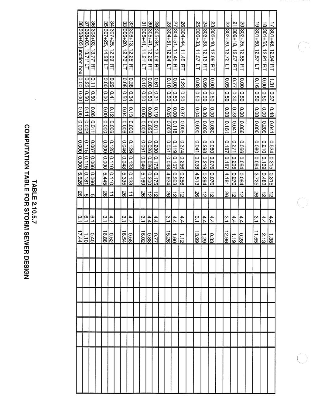
23 4.0 AMOUNT OF RUNOFF FROM THE PROJECT AREA AND ITS UPSTREAM WATERSHED AREA For this project, it has been determined that sixty-two (62) inlets and one (1) manhole/junction box are needed to adequately capture and convey stormwater runoff generated by the anticipated site improvements. These proposed stormwater facilities will greatly enhance the drainage characteristics throughout the project corridor. Therefore, the addition of appropriately spaced inlets significantly reduces the risk of danger to the traveling public (hydroplaning~spread of flow) and flooding (residents). In terms of erosion and sediment pollution control, it is important to intercept stormwater as quickly as possible for these reasons. The existing site drainage pattern will remain the same. All flows will continue to be directed to their existing discharge points (Buck Creek or Silver Creek). The hydraulic design was conducted in accordance with the procedure outlined in PENNDOT s Design Manual Part 2 Chapter 10. Supporting computations and/or results are shown in Appendix I. The total amount of postconstruction runoff (10-year design storm event) for the project is drainage area is cfs based on a total drainage area of acres. No significant increase in surface runoff is expected as no additional impervious area will be created. Therefore, no detention will be required. Pertinent hydraulic data for all drainage systems are provided in Table 2. Drainage System ID 1 (Station to Station ) 2 (Station to Station ) 3 (Station to Station ) Linear Length (ft) # of Inlets Provided Spacing (ft) Drainage Area (acres) Q 10-Post (cfs) Proposed System Outlet Pipe Size (in) Total Table 2. Drainage Summary for S.R The purpose of any roadway drainage plan is to control and reduce the detrimental effects of storm runoff by intercepting it as quickly as possible. Important is the investigation of facilities downstream of the project in order to make certain that they are capable of accepting runoff without causing flooding or erosion. With this in hindsight, the design accomplishes all of these objectives. A conservative approach was undertaken in the design of drainage facilities considering that runoff coefficients chosen for pavement and offsite areas were the upper ends of the ranges shown in Table of PENNDOT s Design Manual Part LOCATION OF WATERS OF THE COMMONWEALTH WHICH MAY RECEIVE RUNOFF WITHIN OR FROM THE PROJECT SITE All project runoff is currently and will remain directed to Afton Lake (which discharges to Buck Creek) and Silver Creek. Afton Lake receives discharge from the northern end of the project whereas the southern half of the project drains to Silver Creek. According to Chapter 93, Water Quality Standards, of the Pennsylvania Code, neither Afton Lake or Silver Creek is designated. Buck Creek is classified as a Warm Water Fishery (WWF) and protected for this use. Buck Creek is a second order stream that flows around the project area from west to east. Silver Creek is considered a third order stream that drains to the Delaware River via the Delaware Canal. Neither stream is stocked with trout. 19
24 6.0 LOCATIONS AND TYPES OF PERIMETER AND ON SITE BMP S The temporary and permanent erosion and sediment pollution control measures are shown on the Erosion and Sediment Pollution Control Plans. The project will be constructed in accordance with the Pennsylvania Department of Transportation 408 Specifications dated 2007, and Standards for Roadway Construction, dated April All erosion and sedimentation control devices will be constructed in accordance with the special details included in the Erosion and Sedimentation Control Plans. 1. An item for "Unforeseen Water Pollution Control" will be included in the construction contract. 2. PennDOT Publication 408 Specification Section Borrow and Waste Areas specifies the erosion and sedimentation control requirements for waste areas outside of the project limits. All waste areas will be coordinated with the District Environmental Unit and all borrow material must meet the provisions of The Management of Fill Policy and Environmental Due Diligence. The existing and proposed (as constructed) drainage system will be protected from sediment and debris during construction with the erosion control devices listed as follows. Appendices II and III contain Standard E&SC worksheets and applicable specifications for the project respectively. The existing drainage systems will continue to collect the runoff from the project area on S.R while the project is being constructed. Any existing pipes to which proposed drainage ties into will be cleaned to maintain these existing systems. Install the following Best Management Practices (BMP s) as indicated on the typical sections and drawings: Temporary Control Measures and Facilities for Use During Earthmoving Activities: 1. Super Filter Fabric Fence Section 865 (Item # Super Silt Barrier Fence, 33 Height) Super silt barrier fence will be installed where shown on the plans at the toe of minor cut and fill slopes. The silt fence will be maintained and replaced if necessary during the entire construction period until permanent vegetative cover is established. Upon stabilization of slopes, the super silt barrier fence will be removed and the area will be restored. The fence will also act as a barrier to prevent impacts to the red-bellied turtle nesting habitat. 2. Vegetative Surface Stabilization Sections 804 & 805 (Item # Seeding-Formula E) (Item # Mulching-Straw) (Item # Mulch Control Netting) All disturbed soil areas not being paved with bituminous materials must be seeded and mulched in accordance with the following requirements and PENNDOT Publication 408: All disturbed areas not at finished grade and which will be redisturbed during construction are shall be seeded with Formula E. Seeds shall be spread at the rates specified below, or as otherwise indicated. Spread seeds within the following dates, or as otherwise indicated or directed. Formula E March 15 to October 15 20
25 Where project conditions warrant, seeding dates may be extended. If extended, either apply full treatment or apply only 50% of the permanent seeding and soil supplements and apply the remaining 50% within the next seeding dates, as directed in writing by the engineer. Disturbed areas on which activities have ceased and which will remain exposed for more than 10 days must be stabilized immediately. During non-germinating periods, mulch must be applied at the recommended rates. Disturbed areas which are not at finished grade and which will be redisturbed within 1 year must be seeded and mulched with a quick growing temporary seeding mixture (Formula E) and mulch. Disturbed areas which are either at finished grade or will not be redisturbed within 1 year must be seeded and mulched with a permanent seed mixture and mulch. Areas mulched during non-germinating periods must be limed, fertilized, seeded and mulched within 10 days of the ending of those periods. The contractor must maintain all seeded areas until final inspection and acceptance of all work in the contract. Any reseeding or regrading must be at the contractor s expense. Any areas which fail to show a uniform stand or fail to germinate, for any reason, must be reseeded with the original mixture. Such reseeding must be maintained until final acceptance of the work. The contractor must spread and compact topsoil to a 4 uniform depth +/- 1.5 in those areas which have been disturbed by work. The topsoil must be raked and trimmed to true lines, and must be free from unsightly variations. Prior to placing topsoil, loosen areas to receive topsoil to a depth of 2 and remove stones and other foreign material 2 or larger in any dimension. On topsoiled areas, blend the initial soil supplements into the soil at least 2, by raking, disking, harrowing, or by another acceptable method. The blending of the supplements into the soil may be performed during tillage operations. Place straw uniformly, in a continuous blanket. Bind with mulch control netting. Formula E Seeding Rate Hay/Straw Mulching Rate 10.0 lb/1000 sy 1,200 lb/1000 sy 3. Filter Bag Inlet Protection Curbed Roadway Filter Bag Inlet Protection (Item # ) Install inlet protection at all existing and proposed inlet facilities to prevent sediment from entering the storm sewer system. Filter bags may be used for drainage areas up to ½ acre. 4. Rock Filter Outlets Sections 703 & 850 (Item # No. 57 Coarse Aggregate) (Item # Rock, Class R-3) The Contractor is responsible for immediately placing a rock filter outlet where silt fence fails. Rock filter outlets will also be placed at level areas of pipe outfalls to prevent sediment laden water from leaving the site unfiltered. 5. Sediment Filter Bag (Item # ) Provide at locations shown on E&SC plans for the filtering of sediment-laden water that has the possibility of rising above controls and leaving the project site (i.e. dewatering of work area for 21
26 proposed pipe outfall). Filter bags shall be made from non-woven geotextile material sewn with high strength, double stitched J type seams. They shall be capable of trapping particles larger than 150 microns. A suitable means of accessing the bag with machinery required for disposal purposes must be provided. Filter bags shall be replaced when they become ½ full. Spare bags shall be kept available for replacement of those that have failed or are filled. Bags shall be located in well-vegetated (grassy) areas, and discharge into stable, erosion resistant areas. Where this is not possible, a geotextile flow path shall be provided. Bags shall not be placed on slopes greater than 5%. The pump discharge hose shall be inserted into the bags in the manner specified by the manufacturer and securely clamped. The pumping rate shall be no greater than 750 gpm or ½ the maximum specified by the manufacturer, whichever is less. Pump intakes should be floating and screened. Filter bags will be inspected daily. If any problem is detected, pumping shall cease immediately and not resume until the problem is corrected. ONLY A 2 OR 4 INCH PUMP SHALL BE USED ALONG WITH A 15 X 15 FILTER BAG ON A BED OF 2B (#57 Coarse Aggregate) STONE WITH SILT FENCE AND/OR HAY BARRIERS BELOW. Permanent Control Measures for Long Term Protection 1. Vegetative Surface Stabilization Sections 804 & 805 (Item # Seeding and Soil Supplements-Formula B) (Item # Seeding and Soil Supplements-Formula C) (Item # Seeding and Soil Supplements-Formula L) (Item # Mulching-Straw) (Item # Mulch Control Netting) All disturbed soil areas not being paved with bituminous materials must be seeded and mulched in accordance with the following requirements and PENNDOT Publication 408: All disturbed slopes steeper than 3:1 where mowing is not anticipated or desired shall be seeded with Formula C. Slopes 3:1 and flatter shall be seeded with Formula L. All other designated slopes (including lawn areas) where mowing may or may not be designated shall be seeded with Formula B. Seeds shall be spread at the rates specified below, or as otherwise indicated. Spread seeds within the following dates, or as otherwise indicated or directed. Formula C Ryegrass Portion: March 1 to October 15 Crownvetch Portion: Anytime except September and October Formula B & L March 15 to June 1 August 1 to October 15 Where project conditions warrant, seeding dates may be extended. If extended, either apply full treatment or apply only 50% of the permanent seeding and soil supplements and apply the remaining 50% within the next seeding dates, as directed in writing by the engineer. Disturbed areas on which activities have ceased and which will remain exposed for more than 10 days must be stabilized immediately. During non-germinating periods, mulch must be applied at 22
27 the recommended rates. Disturbed areas which are not at finished grade and which will be redisturbed within 1 year must be seeded and mulched with a quick growing temporary seeding mixture (Formula E) and mulch. Disturbed areas which are either at finished grade or will not be redisturbed within 1 year must be seeded and mulched with a permanent seed mixture and mulch. Areas mulched during non-germinating periods must be limed, fertilized, seeded and mulched within 10 days of the ending of those periods. The contractor must maintain all seeded areas until final inspection and acceptance of all work in the contract. Any reseeding or regrading must be at the contractor s expense. Any areas which fail to show a uniform stand or fail to germinate, for any reason, must be reseeded with the original mixture. Such reseeding must be maintained until final acceptance of the work. The contractor must spread and compact topsoil to a 4 uniform depth +/- 1.5 in those areas which have been disturbed by work. The topsoil must be raked and trimmed to true lines, and must be free from unsightly variations. Prior to placing topsoil, loosen areas to receive topsoil to a depth of 2 and remove stones and other foreign material 2 or larger in any dimension. Uniformly apply supplements to the areas to be seeded. On topsoiled areas, blend the initial soil supplements into the soil at least 2, by raking, disking, harrowing, or by another acceptable method. The blending of the supplements into the soil may be performed during tillage operations. Place straw uniformly, in a continuous blanket. Bind with mulch control netting. Exposed earth shall be seeded and mulched at the following rates. All non-paved surfaces will be seeded. The maximum surface slope required by this project is 2 horizontal to 1 vertical. Seeded areas that are later disturbed or do not exhibit adequate cover shall be stabilized. Formula C Seeding Rate Bonded Fiber Matrix 9 LB/1000 SY 3000 LB/ACRE (Polymer or Hydrocolloid) 6000 LB/ACRE (Gypsum) Formula L Seeding Rate Straw Mulching Rate 24 LB/1000 SY 1200 LB/1000 SY Formula B Seeding Rate Straw Mulching Rate 21 LB/1000 SY 1200 LB/1000 SY 2. Slope Protection Section 806 (Item # Erosion Control Mulch Blanket) Place on all slopes 3:1 (H:V) and steeper. 3. Riprap Aprons at Pipe Outlets with Flared End Sections Sections 204, 212, & 850 (Item # Class 2 Excavation) (Item # Geotextile, Class 2, Type A) (Item # Rock, Class R-4) Construct riprap protection to prevent scour at pipe outfalls and erosional effects of discharge velocity in downstream channels in agreement with the dimensions called out on the plans. 23
28 7.0 SEQUENCE OF BMP INSTALLATION & REMOVAL The following represents the construction sequencing for the roadway construction work on S.R The contractor will maintain some latitude to conduct his/her operation in the most economical manner as long as the following objectives are met: A. Construct project in stages indicated on the traffic control plans. Place erosion & sediment control measures in accordance with the construction staging indicated on the traffic control plans. B. Maintain two-way traffic on S.R during working hours without a detour. Restore all travel lanes to the normal traffic pattern at the close of each workday. Maintain access to private driveways, Afton Avenue (S.R. 0332), College Avenue, South Street, Van Horn Avenue, and Letchworth Avenue at all times. C. Install soil erosion and sediment pollution control devices prior to disturbing any area. D. Stabilize all disturbed areas immediately. E. All earth disturbance activities shall proceed in accordance with the following sequence. Each stage shall be completed before any following stage is initiated. Clearing and grubbing shall be limited only to those areas described in each stage. 1. Install super silt barrier fence along the southerly bank at Silver Creek, as indicated on the plan, for construction of the storm drain outfall and to prevent impacts to the red-bellied turtle nesting habitat. Place the pumped water filter bag in the location agreed to at the pre-construction meeting with Bucks County Conservation District. 2. Clear and grub the minimum area necessary for construction of the drainage system that outfalls to Silver Creek. Minimize disturbance as much as possible. 3. Construct the storm drain outfall system from Station , Right to Station , Right, between November 1 and March 31, and provide riprap apron outlet protection for the outlet to Silver Creek as depicted on the plan. Permanently stabilize areas around the southerly bank at Silver Creek with seed and mulch and provide erosion control mulch blankets on all disturbed slopes steeper than 3:1. When areas are stabilized, remove super silt barrier fence and pumped water filter bag. Areas disturbed during removal of the super silt barrier fence and pumped water filter bag must be stabilized immediately. 4. Install silt sacs within all existing inlets throughout the project area. Construct remaining drainage from Station to Station and place silt sac protection on all inlets installed. Backfill trenches and re-establish pavement section to base course the same day as excavation and restore full traffic access as required. Cover inlets in order to prevent stormwater entry unless downstream connections are in place. 5. Install curb and sidewalk. Permanently stabilize all disturbed areas with seed and mulch. Mill and overlay roadway from Station to Station Remove silt sac inlet protection. Clean any existing inlets, manholes, and pipes to which proposed drainage is connected. Details for erosion & sediment pollution control are indicated on the Plan (See Appendix IV). All other work will be done in accordance with PENNDOT S Publication 408 Specifications and the special provisions of the contract. An item for Unforeseen Water Pollution Control will be included in the construction contract. 24
29 8.0 MAINTENANCE PROGRAM 1. The Contractor will be responsible for developing and submitting an Erosion and Sediment Pollution Control Plan for any offsite borrow, staging, and/or waste areas as per Publication 408/2007, Section Provide a copy of the approval to the Engineer prior to starting work. 2. Remove all excavated material, pieces of concrete, sediment, etc. to be wasted from the job site. Establish a waste area in accordance with Publication 408/2007 Section Stabilize waste areas using perimeter controls and/or temporary seeding. 4. Inspect all erosion and sediment pollution control devices daily and after each rainfall/runoff event. Repair all deficiencies found within one (1) working day. 5. Remove all accumulated sediments as required to keep erosion control devices functional. In all cases, remove deposits where accumulations reach one-half of the above-ground height of the silt barrier fence. Repair all undercutting or erosion immediately with compacted backfill materials. Any fence section which has been undermined or topped must be immediately replaced with a rock filter outlet. Adhere to the manufacturer s recommendations for replacing erosion control devices due to weathering, etc. Sediment deposits remaining in place after the devices are no longer required must be dressed to conform with existing grade and permanently stabilized. 6. At the end of each construction day, all sediment deposited on public roadways will be removed and returned to the construction site. 7. Reseed all areas disturbed by construction activities immediately. Seeded surfaces will be maintained as necessary to promote the rapid growth of thick grass cover. 8. All excavated sediments will be either spread over areas not yet stabilized or removed from the site to an established waste site. 9. Until the site is stabilized, all erosion and sediment control BMP s must be maintained properly. Inspect all BMP s after each runoff event and on a weekly basis. All preventative and remedial maintenance work, including clean out, repair, replacement, regrading, reseeding, remulching, and renetting must be performed immediately. If erosion and sediment control BMP s fail to perform as expected, replacement BMP s or modifications of those installed is required. STANDARD EROSION AND SEDIMENT POLLUTION CONTROL PLAN NOTES The following general notes will be included, upon acceptance, in the contract documents: 1. Stockpile heights must not exceed 35 feet; stockpile slopes must not exceed 2:l. 2. The operator/responsible person (O/RP) on site shall assure that the approved erosion and sediment control plan is properly and completely implemented. 3. Immediately upon discovering unforeseen circumstances posing the potential for accelerated erosion and/or sediment pollution, the O/RP shall implement appropriate Best Management Practices (BMPs) to eliminate the potential for accelerated erosion and/or sediment pollution. 4. The O/RP shall assure that an erosion and sediment control plan has been prepared, approved by the Bucks County Conservation District and is being implemented and maintained for all soil and/or rock spoil and borrow areas regardless of their locations. 5. All pumping of sediment-laden water shall be through a sediment control BMP such as a pumped water filter bag discharging over undisturbed areas. 6. A copy of the approved erosion and sediment control plan must be available on the project site at all times. 25
30 7. Erosion and sediment BMPs must be constructed, stabilized and functional before site disturbance begins within the tributary areas of those BMPs. 8. After final site stabilization has been achieved, temporary erosion and sediment BMP controls must be removed. Areas disturbed during the removal of the BMPs must be stabilized immediately. 9. At least seven (7) days before starting any earth disturbance activity, the O/RP shall invite all contractors involved in that activity, the landowner, all appropriate municipal officials, the erosion and sediment control plan designer and the Bucks County Conservation District to a pre-construction meeting. Also, at least three days before starting any earth disturbance activity, all contractors involved in that activity shall notify the Pennsylvania One-Call System Inc. at to determine any underground utilities locations. 10. Immediately after earth disturbance activity ceases, the O/RP shall stabilize any areas disturbed by the activity. During non-germinating periods, mulch must be applied at specified rates. Disturbed areas that are not at finished grade and which will be re-disturbed within one year must be stabilized in accordance with temporary vegetative stabilization specifications. 11. Disturbed areas that are at finished grade or which will not be re-disturbed within one year must be stabilized in accordance with permanent vegetative stabilization specifications. 12. An area shall be considered to have achieved final stabilization when it has a minimum uniform 70% (percent) vegetative or other permanent non-vegetative cover with a density sufficient to resist accelerated surface erosion and subsurface characteristics sufficient to resist sliding and other movements. 13. Upon the installation of temporary sediment basin riser(s), a qualified site representative shall conduct an immediate inspection of the riser(s), whereupon the Bucks County Conservation District shall be notified in writing that the riser is sealed (watertight). 14. At stream crossing, a 50-foot buffer shall be maintained. On buffers, clearings, sod disturbances and excavations, equipment traffic should be minimized. Activity such as stacking logs, burning cleared brush, discharging rainwater from trenches, welding pipe sections, refueling and maintaining equipment should be avoided within buffer zones. 15. Until a site is stabilized, all erosion and sediment BMPs must be maintained properly. Maintenance must include inspections of all erosion control BMPs after each runoff event and on a weekly basis. All preventative and remedial maintenance work, including cleanout, repair, replacement, re-grading, reseeding, re-mulching and re-netting must be performed immediately. If erosion and sediment control BMPs fail to perform as expected, replacement BMPs, or modifications of those installed, will be required. 16. Sediment removed from BMPs shall be disposed of on-site in landscaped areas outside of steep slopes, wetlands, floodplains or drainage swales and immediately stabilized or placed in soil stockpiles and stabilized. 17. All building material and wastes must be removed from the site and recycled in accordance with DEP s Solid Waste Regulations (25 PA Code et seq., et seq., and et seq.), and/or any additional local, state or federal regulations. No building materials (used or unused) or waste materials shall be burned, buried, dumped or discharged at the site. 26
31 9.0 MEASURES FOR THE RECYCLING OR DISPOSAL OF MATERIALS FROM THE PROJECT SITE As called for under Section of PENNDOT Publication 408/2007, the Contractor shall satisfactorily remove and dispose of all existing highway structures and materials which are not to remain in place or to be used in new construction. This includes existing pavement, concrete, stone, guide rail, drainage structures, or unsuitable soil. Unless otherwise directed, dispose of these structures and materials off the project site. Coordinate any material salvage, including temporary storage and delivery, with the Department. However, if indicated, the Department will retain drainage pipes, drainage grates or castings, guide rail posts, guide rail, bridges not under the authority of the Department, and/or portions of Department bridges. Such structures on all other highways become the property of the local authorities having jurisdiction. If the local authorities do not want to retain any portion or portions of structures or material under their jurisdiction, then remove and dispose of them off the project site. The Contractor shall locate proposed areas for disposal of waste material, when required and shall comply with all requirements as laid out in Section of PENNDOT Publication 408/2007. If the Department has previously selected areas from which to obtain borrow or areas in which to deposit waste, the proposal will specify the location(s). For such designated area(s), the Contractor shall complete the standard agreement as specified for Non-Designated Areas. The Department will provide all applicable permits and Erosion and Sediment Pollution Control Plans. 27
32 REFERENCES & BIBLIOGRAPHY 1. Pennsylvania Department of Environmental Protection, Erosion and Sediment Pollution Control Manual, March Pennsylvania Department of Environmental Protection, Erosion and Sedimentation Control Plan Development Checklists, Standard Worksheets, Details and Notes, August Pennsylvania Association of Conservation Districts, Inc., Keystone Chapter, Soil and Water Conservation Society, Pennsylvania Department of Environmental Protection, Natural Resources Conservation Service, Pennsylvania Handbook of Best Management Practices for Developing Areas, Pennsylvania Department of Transportation, Roadway Specifications Publication 408, April Pennsylvania Department of Transportation, Design Manual, Part 2, Highway Design, Publication 13M, October 2002 (Revised June 2006). 6. Pennsylvania Department of Transportation, Standards for Roadway Construction Publication 72M, April 2004 (Revised March 2006). 7. U.S. Department of Agriculture, Soils Conservation Service, Soil Survey of Bucks County, Pennsylvania, September U.S. Department of the Interior, Geologic Survey, U.S.G.S. 7.5 Minute Topographic Quadrangle Maps, Trenton West NJ, PA, July 1,
33 APPENDIX I. DRAINAGE CALCULATIONS

34

35
36

37
38 APPENDIX II. E&SC WORKSHEETS
39 STANDARD WORKSHEET #5 Super Filter Fabric Fence PROJECT NAME: S.R Section CS2 Main Street Drainage Improvements LOCATION: Yardley Borough, Bucks County, PA PREPARED BY: RJY DATE: 10/02/07 CHECKED BY: DATE: CONSTRUCTION DETAIL: Filter fabric fence must be installed at existing level grade. Both ends of each fence section must be extended at least 8 feet upslope at 45 degrees to the main fence alignment. Sediment must be removed where accumulations reach 1/ 2 the above ground height of the fence. Any fence section which has been undermined or topped must be immediately replaced with a rock filter outlet. See Rock Filter Outlet Detail. BARRIER NO. LOCATION SLOPE- PERCENT SLOPE LENGTH ABOVE BARRIER (FT) , Right to , Right 50 (2:1) 19.5
40 STANDARD WORKSHEET #23 Riprap Apron Outlet Protection PROJECT NAME: S.R Section CS2 Main Street Drainage Improvements LOCATION: Yardley Borough, Bucks County, PA PREPARED BY: RJY DATE: 10/02/07 CHECKED BY: DATE: CONSTRUCTION DETAIL: NOTE: SHOW ALL DETAILS AND CONSTRUCTION DIMENSIONS ON PLAN DRAWINGS. OUTLET NO , Right PIPE DIA. Do (in.) TAILWATER CONDITION (Max or Min) Q (CFS) V* (FPS) RIPRAP SIZE La (ft) W (ft) 18 MIN R The anticipated velocity (V) should not exceed the maximum permissible shown in the Program Manual for the proposed riprap protection. * Because of outlet velocity, use Rock Energy Dissipator for Outlet Treatment (See RC-70M).
41
42 APPENDIX III. SPECIFICATIONS
43
44
45
46
47
48
49
50
51

52
53
54
55

56
57

58
59
60
61
62
63
64
65
66
67
68
69
70
71
72

73
74
75
76
77
78
79
80
81
82
83
84
85
86
87
88
89
90
91
92
93
94
95
96
97
98
99
100
101
102
103 ITEM FILTER BAG INLET PROTECTION (CURBED ROADWAY) DESCRIPTION This work is the furnishing, installation, maintenance, and removal of filter bag inlet protection to prevent silt and debris from entering inlets for the type indicated. MATERIALS Filter bags capable of trapping particles larger than 150 Microns. 25 mm (1 ) rebars (Section 1002). Sandbags. 50 mm (2 ) x 50 mm (2 ) x 19 mm (3/4 ) rubber blocks. 6 mm (1/4 ) nylon rope. CONSTRUCTION Install at inlet locations shown on the Erosion and Sediment Pollution Control Plans. Wherever filter bags are used, they should be installed according to the manufacturer s specifications. Insert the nylon rope through the filter bag and rubber blocks on the inside of the bag to provide expansion restraint. Lay the bag over the inlet top unit. Slide rebars through eyelets of the filter bag for bag removal from the inlet. Place grate over inlet top unit to hold the filter bag in place. Place sandbags to block any water from flowing into the curb openings. Inlet filter bags should be inspected on a weekly basis and after each runoff event. Filter bags should be cleaned and/or replaced when the bag is ½ full. Damaged filter bags should be replaced. Needed repairs should be initiated immediately after the inspection. Maintain the inlet protection for the duration of construction, as directed. Maintain earthen berm in roadway until roadway is stoned. Road subbase berm on roadway to be maintained until roadway is paved. A 150 mm (6 ) minimum height asphalt berm shall be maintained until the roadway surface receives the final coat. Earthen berms in channels shall be maintained until permanent stabilization is completed. MEASUREMENT AND PAYMENT Each
June Pennsylvania Department of Transportation Engineering District Herr Street Harrisburg, PA 17103
 EROSION & SEDIMENT CONTROL REPORT FOR S.R. 0462 BOX CULVERT REPLACEMENT OVER TRIBUTARY TO STRICKLER RUN WEST HEMPFIELD TWP., LANCASTER CO. Prepared for: June 2006 Pennsylvania Department of Transportation
Shelbyville, KY Stormwater Best Management Practices. Section 2 EROSION PREVENTION AND SEDIMENT CONTROL PLAN
 Section 2 EROSION PREVENTION AND SEDIMENT CONTROL PLAN 2.1 Requirements The City of Shelbyville, KY will require an Erosion Prevention and Sediment Control (EPSC) Plan for most types of development construction.
PLAN SUBMITTER'S CHECKLIST
 Page 1 of 8 PLAN SUBMITTER'S CHECKLIST FOR EROSION AND SEDIMENT CONTROL PLANS Please fill in all blanks and reference the plan sheets/pages where the information may be found, where appropriate, or write
Gloucester County PLAN SUBMITTER'S CHECKLIST
 Page 1 of 9 Gloucester County PLAN SUBMITTER'S CHECKLIST FOR EROSION AND SEDIMENT CONTROL PLANS Please fill in all blanks and please reference the plan sheets/pages where the information may be found,
Erosion & Sediment Control Plan Application Form & Checklist
 Erosion & Sediment Control Plan Application Form & Checklist GENERAL INFORMATION Application Date: Project Address: Tax Map / Parcel Number(s): PROPERTY OWNER / DEVELOPER Firm Name: Contact Person: Title:
Project: Developer/Designer: Reviewer: I. Narrative: 1. Project Description: Describes the nature and purpose of the land disturbing activity.
 City of Charlottesville, Virginia Erosion and Sediment Control Plan Review Checklist 610 East Market Street, Charlottesville, VA 22902 Telephone 434-970-3182; Fax 434-970-3359 Project: Developer/Designer:
Structural Storm Water Best Management Practices (BMPs)
") Structural Storm Water Best Management Practices (BMPs) Storm Water Permitting: The SWPPP Revealed By Deron Austin, PE January 11, 2006 3:30-5:00 PM Orlando, Florida Presentation Outline Preface About
Structural Storm Water Best Management Practices (BMPs) Storm Water Permitting: The SWPPP Revealed By Deron Austin, PE January 11, 2006 3:30-5:00 PM Orlando, Florida Presentation Outline Preface About
EROSION & SEDIMENT CONTROL
 EROSION & SEDIMENT CONTROL Surface Water Protection During Well Site Construction Kelly Kees, PE WVDEP, Office of Oil and Gas SEDIMENT & EROSION CONTROL PLANS Per West Virginia State Code 22-6-6(d) 22-6A-7(c),
City of Stoughton Erosion Control Permit Application (effective 2/6/2018)
") City of Stoughton Erosion Control Permit Application (effective 2/6/2018) Incomplete applications will not be accepted Project Name: Address of subject property: Landowner Name(s): Applicant Name: Landowner
City of Stoughton Erosion Control Permit Application (effective 2/6/2018) Incomplete applications will not be accepted Project Name: Address of subject property: Landowner Name(s): Applicant Name: Landowner
Plan Review Checklist
 Plan Review Checklist FOR EROSION AND SEDIMENT CONTROL PLANS _ Minimum Standards - All applicable Minimum Standards must be addressed. All minimum Standards must be adhered to during the entire project
Draft Rhode Island Stormwater Design and Installation Standards Manual
 Draft Rhode Island Stormwater Design and Installation Standards Manual Summary The May 2009 Public Review Draft version of the RI Stormwater Design and Installation Standards Manual consists of approximately
Urban Conservation Practice Physical Effects ESTABLISHMENT, GROWTH, AND HARVEST NUTRIENT MANAGEMENT
 NOT WELL 800 - Urban Stormwater Wetlands A constructed system of shallow pools that create growing conditions for wetland plants to lessen the impacts of stormwater quality and quantity in urban areas.
SUPPORTING DOCUMENT STORMWATER POLLUTION PREVENTION PLAN (SWPPP) NARRATIVE
 NARRATIVE") SUPPORTING DOCUMENT STORMWATER POLLUTION PREVENTION PLAN (SWPPP) NARRATIVE Please complete this narrative form and submit with your SWPPP drawings. Refer to Kitsap County Stormwater Design Manual Vol.
SUPPORTING DOCUMENT STORMWATER POLLUTION PREVENTION PLAN (SWPPP) NARRATIVE Please complete this narrative form and submit with your SWPPP drawings. Refer to Kitsap County Stormwater Design Manual Vol.
Erosion Control for Home Builders in the. City of Jacksonville
 Erosion Control for Home Builders in the City of Jacksonville Eroding construction sites are a leading cause of water quality problems in Jacksonville. For every acre under construction, about a dump truck
Project Applicant Checklist for NPDES Permit Requirements SAN MATEO COUNTYWIDE STORMWATER POLLUTION PREVENTION PROGRAM
 Project Applicant Checklist for NPDES Permit Requirements SAN MATEO COUNTYWIDE STORMWATER POLLUTION PREVENTION PROGRAM I. PROJECT DATA Project Name Bay Meadows Development Phase II Project Address 2600
STANDARD SPECIFICATIONS SECTION TEMPORARY EROSION AND SEDIMENT CONTROL
 STANDARD SPECIFICATIONS SECTION 01570 TEMPORARY EROSION AND SEDIMENT CONTROL PART 1 GENERAL 1.1 DESCRIPTION A. Section includes requirements, procedures, and methods related to responsibilities for providing
5. LOW IMPACT DEVELOPMENT DESIGN STANDARDS
 5. LOW IMPACT DEVELOPMENT DESIGN STANDARDS Low Impact Development (LID) requires a shift in stormwater management away from conveying runoff to a small number of downstream points through hydraulically
APPENDIX A SIMPLIFIED APPROACH TO STORMWATER MANAGEMENT FOR SMALL PROJECTS. In West Sadsbury Township, Chester County, Pennsylvania
 APPENDIX A SIMPLIFIED APPROACH TO STORMWATER MANAGEMENT FOR SMALL PROJECTS In West Sadsbury Township, Chester County, Pennsylvania TABLE OF CONTENTS I. Introduction 3 II. Importance of Stormwater Management
PERMANENT SEEDING. Overview of Sedimentation and Erosion Control Practices. Practice no. 6.11
 Overview of Sedimentation and Erosion Control Practices Practice no. 6.11 PERMANENT SEEDING Permanent vegetation controls erosion by physically protecting a bare soil surface from raindrop impact, flowing
SECTION 900 TURF ESTABLISHMENT
 SECTION 900 901.0 DESCRIPTION This section covers the furnishing of all labor, materials, tools, equipment and performances of all work and services necessary or incidental to turf restoration as indicated
SECTION 6. Routine Maintenance Activity Details
 SECTION 6 Routine Maintenance Activity Details 80. DEBRIS REMOVAL When Deadfall, and other objects, such as shopping carts, tires, appliances, and mattresses have accumulated in the drain. Why To prevent
A. Install all temporary erosion control measures (in accordance with MNDOT General Conditions 2573) prior to site disturbance.
 prior to site disturbance.") The language provided in these specifications is meant to serve as a reminder and provide a generic example of the type of language that should be provided in final construction documents. This language
The language provided in these specifications is meant to serve as a reminder and provide a generic example of the type of language that should be provided in final construction documents. This language
Wisconsin Contractors Institute Continuing Education
 Wisconsin Contractors Institute Continuing Education Erosion & Sediment Control Course # 12775 2 hours Wisconsin Contractors Institute N27 W23953 Paul Road, Suite 203 Pewaukee, WI 53072 Website: www.wicontractorsinstitute.com
A. Install all temporary erosion control measures (in accordance with MNDOT General Conditions 2573) prior to site disturbance.
 prior to site disturbance.") The language provided in these specifications is meant to serve as a reminder and provide a generic example of the type of language that should be provided in final construction documents. This language
The language provided in these specifications is meant to serve as a reminder and provide a generic example of the type of language that should be provided in final construction documents. This language
Town of Essex Small Site Erosion Control Guide
 Town of Essex Small Site Erosion Control Guide Why do we need to protect against erosion? Water Quality: Erosion and the transport of sediment and pollutants impacts the water quality of nearby streams
SOIL EROSION AND SEDIMENT CONTROL
 SOIL EROSION AND SEDIMENT CONTROL SECTION 1: AUTHORITY, TITLE AND PURPOSE 11. STATUTORY AUTHORIZATION This ordinance is adopted pursuant to the provisions of the Federal Water Pollution Control Act 86
Department of Agriculture. Conservation Service. United States. Natural Resources REVISED 8/26/16
 GENERAL NOTES: SYMBOL LEGEND 1. All work shall comply with the constriction specifications, drawings, project-specific quality assurance plan and other contract requirements. 2. All notes on the drawings
SILT FENCE MACHINE SLICED ERO-1A STEEL FENCE POST (T-POST), MINIMUM 5' LONG, 6' MAXIMUM SPACING.
, MINIMUM 5' LONG, 6' MAXIMUM SPACING.") STEEL FENCE POST (T-POST), MINIMUM 5' LONG, 6' MAXIMUM SPACING. ATTACH FABRIC TO POSTS WITH MINIMUM 3 ZIP TIES (50 LB. TENSILE) PER POST IN TOP 8" OF FABRIC. MONOFILAMENT GEOTEXTILE FABRIC PER MNDOT TABLE
STEEL FENCE POST (T-POST), MINIMUM 5' LONG, 6' MAXIMUM SPACING. ATTACH FABRIC TO POSTS WITH MINIMUM 3 ZIP TIES (50 LB. TENSILE) PER POST IN TOP 8" OF FABRIC. MONOFILAMENT GEOTEXTILE FABRIC PER MNDOT TABLE
Huntington Stormwater Utility
 Huntington Stormwater Utility Stormwater Management & Sediment and Erosion Control Requirements for Construction Sites Authorized by Huntington City Code Articles: 971, 970, 930, 935, 955, Revised April
Urban Planning and Land Use
 Urban Planning and Land Use 701 North 7 th Street, Room 423 Phone: (913) 573-5750 Kansas City, Kansas 66101 Fax: (913) 573-5796 Email: planninginfo@wycokck.org www.wycokck.org/planning To: From: City Planning
a. Site Topography and Relationship to Surrounding Topography
 C. Topography and Slopes 1. Existing Conditions a. Site Topography and Relationship to Surrounding Topography The Site is gently rolling, as is the surrounding topography (Figure I.A-8). The Property is
CHECKLIST FOR PHASE II DRAINAGE REPORT
 I. COVER SHEET CHECKLIST FOR PHASE II DRAINAGE REPORT A. Name of Project B. Address C. Owner D. Developer E. Engineer F. Submittal date and revision dates as applicable II. GENERAL LOCATION AND DESCRIPTION
EROSION & SEDIMENTATION CONTROL NARRATIVE AND CALCULATIONS
 EROSION & SEDIMENTATION CONTROL NARRATIVE AND CALCULATIONS SR 1026, SECTION C01 BRIDGE REPLACEMENT WEST PIKELAND TOWNSHIP CHESTER COUNTY, PENNSYLVANIA April 3, 2006 TPD PROJECT #PA06.I.00095 Prepared For:
EROSION & SEDIMENT CONTROL
 EROSION & SEDIMENT CONTROL 1 EROSION & SEDIMENT CONTROL Effective Soil & Water Protection Whether you want to prevent soil erosion caused by rain, water and wind, or protect waterways from inevitable build
SOP 6: Erosion and Sedimentation Control SOP 6: EROSION AND SEDIMENTATION CONTROL
 Standard Operating Procedures Central Massachusetts Regional Stormwater Coalition SOP 6: Erosion and Sedimentation Control SOP 6: EROSION AND SEDIMENTATION CONTROL Erosion and sedimentation from land-disturbing
A. INTRODUCTION AND SUMMARY OF FINDINGS B. EXISTING CONDITIONS. Table 10-1 Adjacent Storm Drains
 Chapter 10: Stormwater Management A. INTRODUCTION AND SUMMARY OF FINDINGS This chapter describes existing and proposed stormwater management on the Site. Potential impacts to stormwater infrastructure
General Information. Site Conditions. 9b 9b. 9a 1b. Best Management Practices Illustration
 Model Construction SWPPP Planning & Development Services 1800 Continental Place Mount Vernon WA 98273 voice 360-416-1320 inspections 360-416-1330 www.skagitcounty.net/stormwaterpermitting Permit #: General
STORMWATER SITE PLAN INSTRUCTIONS AND SUBMITTAL TEMPLATE Medium and Large Projects
 DEPARTMENT OF COMMUNITY DEVELOPMENT 621 Sheridan Street, Port Townsend, WA 98368 Tel: 360.379.4450 Fax: 360.379.4451 Web: www.co.jefferson.wa.us/communitydevelopment E-mail: dcd@co.jefferson.wa.us STORMWATER
STORMWATER MANAGEMENT CODES ANALYSIS RICHLAND COUNTY, SC SITE PLANNING ROUNDTABLE
 STORMWATER MANAGEMENT CODES ANALYSIS RICHLAND COUNTY, SC SITE PLANNING ROUNDTABLE Codes analyses for each subcommittee were completed to assist participants of the Richland County Site Planning Roundtable.
MANUAL OF DESIGN, INSTALLATION, AND MAINTENANCE REQUIREMENTS FOR STORMWATER MANAGEMENT PLANS
 MANUAL OF DESIGN, INSTALLATION, AND MAINTENANCE REQUIREMENTS FOR STORMWATER MANAGEMENT PLANS May 2007 SECTION 1 Responsibility of Applicant TABLE OF CONTENTS A. Stormwater Management Plan Required Information
CITY OF TUMWATER 555 ISRAEL RD. SW, TUMWATER, WA (360) (360) (FAX)
 (360) (FAX)") CITY OF TUMWATER 555 ISRAEL RD. SW, TUMWATER, WA 98501 (360) 754-4180 (360) 754-4126 (FAX) Email: cdd@ci.tumwater.wa.us APPENDIX II-C SHORT FORM CONSTRUCTION STORMWATER POLLUTION PREVENTION PLAN (SWPPP)
CITY OF TUMWATER 555 ISRAEL RD. SW, TUMWATER, WA 98501 (360) 754-4180 (360) 754-4126 (FAX) Email: cdd@ci.tumwater.wa.us APPENDIX II-C SHORT FORM CONSTRUCTION STORMWATER POLLUTION PREVENTION PLAN (SWPPP)
VALLEY COUNTY MINIMUM STANDARDS FOR PRIVATE ROAD DESIGN AND CONSTRUCTION
 MINIMUM STANDARDS FOR PRIVATE ROAD DESIGN AND CONSTRUCTION Adopted November 28, 2005 TABLE OF CONTENTS DEFINITION OF TERMS...II I. DESIGN CRITERIA... 1 A. GENERAL DESIGN CRITERIA... 1 B. ROADWAY CLASSIFICATION...
CHAPTER 9 STORM DRAINAGE. Minimum Requirements for New Development and Redevelopment
 CHAPTER 9 STORM DRAINAGE 9.01 General The standards established by this chapter are intended to represent the minimum standards for the design and construction of storm drainage facilities. 9.02 Design
Soil Erosion & Sediment Control Plan Requirements for Submittal to the Cape Atlantic Conservation District
 Soil Erosion & Sediment Control Plan Requirements for Submittal to the Cape Atlantic Conservation District The following is a list of the minimum requirements required on Soil Erosion and Sediment Control
MARBLE RIVER WIND POWER PROJECT Agricultural Protection Measures
 MARBLE RIVER WIND POWER PROJECT Siting Considerations 1. Locate access roads and, to the extent allowed by local laws, wetlands and topography, individual wind turbines and other structures along field
Vegetated Filter Strips and Buffers
 3.15 Sediment Control Description: Buffer strips (existing vegetation) and filter strips (planted vegetation) are sections of vegetated land adjacent to disturbed areas. They are designed with low slopes
POST CONSTRUCTION STORMWATER MANAGEMENT FOR "WHITE OAK SEWER INTERCEPTOR"
 POST CONSTRUCTION STORMWATER MANAGEMENT PLAN FOR "WHITE OAK SEWER INTERCEPTOR" Located in Newberry Township, York County March 21, 2008 Prepared by: Mellott Engineering, Inc. 7500 Devonshire Heights Road
4. Contractor (and subcontractors if applicable) certification statement(s)
 certification statement(s)") CHEMUNG COUNTY STORMWATER COALITION STORMWATER POLLUTION PREVENTION PLAN (SWPPP) SUBMITTAL CHECKLIST GENERAL INFORMATION: 1. Owner/Operator name, legal address, phone number 2. Copy of signed Notice of
CHEMUNG COUNTY STORMWATER COALITION STORMWATER POLLUTION PREVENTION PLAN (SWPPP) SUBMITTAL CHECKLIST GENERAL INFORMATION: 1. Owner/Operator name, legal address, phone number 2. Copy of signed Notice of
5/15/2013. Basin Area. Vegetation. Rainfall & Runoff. Soil Type. Topics. Factors Influencing Erosion. Factors Influencing Erosion
 Topics Erosion, TESC and Construction sequencing Procedures and timing Remedies for failing sites Curtis Hinman WSU Extension and Bio Systems Eng. Faculty Low Impact Development Specialist chinman@wsu.edu
Vegetated Filter Strips and Buffers
 3.15 Sediment Control Description: Buffer strips (existing vegetation) and filter strips (planted vegetation) are sections of vegetated land adjacent to disturbed areas. They are designed with low slopes
Soil Erosion and Sediment Control
 PDHonline Course C188 (3 PDH) Soil Erosion and Sediment Control Instructor: John Poullain, PE 2012 PDH Online PDH Center 5272 Meadow Estates Drive Fairfax, VA 22030-6658 Phone & Fax: 703-988-0088 www.pdhonline.org
ACT 167 STORMWATER CONSISTENCY VERIFICATION REPORT FOR CHESTER COUNTY 1.0 INTRODUCTION
 ACT 167 STORMWATER CONSISTENCY VERIFICATION REPORT FOR CHESTER COUNTY 1.0 INTRODUCTION Tetra Tech, Inc. (Tt) has prepared this Act 167 Stormwater Consistency Verification Report. The report verifies consistency
C-10. Disconnected Impervious Surface
 C-10. Disconnected Impervious Surface Design Objective Disconnected Impervious Surface (DIS) is the practice of directing stormwater runoff from built-upon areas to properly sized, sloped and vegetated
Section 9 Landscaping and Street Trees
 Section 9 Landscaping and Street Trees GENERAL REQUIREMENTS...9-1 I. MATERIALS...9-1 9.1 GRASS...9-1 9.2 STREET TREES...9-1 A. General...9-1 B. Species...9-2 C. Design Standards...9-2 9.3 LANDSCAPING...9-3
Appendix I. Checklists
 Appendix I Checklists Town of Greenwich Drainage Manual Department of Public Works - Engineering Division Town Hall - 101 Field Point Road, Greenwich, CT 06836-2540 Phone 203-622-7767 - Fax 203-622-7747
Chapter 4 - Preparation of Stormwater Site Plans
 Chapter 4 - Preparation of Stormwater Site Plans The Stormwater Site Plan is the comprehensive report containing all of the technical information and analysis necessary for the City to evaluate a proposed
CHAPTER 102 REQUIREMENTS CRITCAL STAGES DURING CONSTRUCTION ACTIVITIES
 CHAPTER 102 REQUIREMENTS CRITCAL STAGES DURING CONSTRUCTION ACTIVITIES TOPICS Steps Prior to construction Pre-Construction Meeting Defining the Critical Stages with the Contractor Brady s Run Lake Site
Stormwater Pollution Prevention Plan Oneonta Heights Oneonta, NY TABLE OF CONTENTS PAGE
 Oneonta Heights Oneonta, NY TABLE OF CONTENTS PAGE I. INTRODUCTION... 2 II. EXISTING CONDITIONS... 3 A. Topography/ Drainage... 3 B. Soils... 3 C. Wetlands... 3 D. Floodplain... 3 E. NYSDEC Environmental
WQ-23 MOUNTAINOUS AND STEEP SLOPE SITES
 Greenville County Technical Specification for: WQ-23 MOUNTAINOUS AND STEEP SLOPE SITES 1.0 Mountainous and Steep Slope Sites 1.1 Description The geographic locations of portions of Greenville County are
Table 4.7.1: Swales Potential Application and Storm Water Regulation
 4.7. Swales A swale is a vegetated open channel, planted with a combination of grasses and other herbaceous plants, shrubs, or trees. A traditional swale reduces peak flow at the discharge point by increasing
The Low Risk Site Handbook
 The Low Risk Site Handbook for Erosion Prevention and Sediment Control The content of this Handbook is adapted from the New York State Standards and Specifications for Erosion and Sediment Control-August
PROPOSED DRAINAGE PATTERNS
 1121 1118.50 Basin Floor 1120 1119 0 N 100 200 PROPOSED DRAINAGE PATTERNS Deroiser Drive Riverwood Drive County 260 0 100 200 Project Name: Riverwood Drive LITTLE FALLS TOWNHOMES Project Location: LITTLE
12/7/2007. Christopher B. Burke Engineering West, Ltd Aux Sable Creek Watershed Plan Update 1
 The ABC s of BMP s Aux Sable Watershed Plan St. Charles, IL Why are BMP s Important Best Management Practices (BMPs) developed as a set of practices which help to achieve goals of the Clean Water Act and
TOWNSHIP OF LOGAN SOIL & FILL IMPORTATION AND PLACEMENT APPLICATION SUBMITTAL CHECKLIST
 TOWNSHIP OF LOGAN SOIL & FILL IMPORTATION AND PLACEMENT APPLICATION SUBMITTAL CHECKLIST Applications: 5 copies of application - Applicant will reproduce the copies at his/her costs. The Township Clerk
Plan of Development Mountain Valley Pipeline Project. APPENDIX M Winter Construction Plan
 APPENDIX M October 20, 2017 Appendix M Prepared by: October 20, 2017 TABLE OF CONTENTS 1.0 INTRODUCTION... M-1 2.0 STABILIZATION/WINTERIZATION... M-2 3.0 EROSION AND SEDIMENT CONTROL MEASURES... M-3 4.0
STORM WATER MANAGEMENT PLAN APPLICATION Manheim Borough
 STORM WATER MANAGEMENT PLAN APPLICATION Manheim Borough DATE Application is hereby made to Manheim Borough for the issuance of a Storm Water Management Plan approval pursuant to the Manheim Borough Storm
Small Town Sustainable Stormwater Solutions
 Small Town Sustainable Stormwater Solutions Kathryn Hamilton, RLA, ASLA Westmoreland Conservation District PA/DE ASLA Annual Meeting April 8-9, 8 2011 Urban, Industrial, Residential, Agricultural Flooding,
Project Name: Project Address or Location: Principal Designer Name and Company: Principal Designer Phone Number:
 SECTION 1: GENERAL INFORMATION Plan Submission Date: Total Disturbed Acreage: _ Project Name: Project Address or Location: Principal Designer Name and Company: Principal Designer Phone Number: email: SECTION
M-231 and Water Quality. Ottawa County Water Quality Forum November 21, 2016 James Fortney, MDOT
 M-231 and Water Quality Ottawa County Water Quality Forum November 21, 2016 James Fortney, MDOT M-231 Facts: 7-Miles long 2-Lane Limited Access Highway Connects I-96 and M-45 M-231 Facts: Includes Michigan
SIMPLIFIED APPROACH TO STORMWATER MANAGEMENT FOR SMALL PROJECTS
 SIMPLIFIED APPROACH TO STORMWATER MANAGEMENT FOR SMALL PROJECTS Introduction As required by federal and state law, the Borough of Swarthmore has adopted regulations that affect stormwater runoff and surface
SMALL PROJECTS SIMPLIFIED APPROACH
 SMALL PROJECT APPLICATION AND STORMWATER MANAGEMENT DESIGN ASSISTANCE MANUAL FOR SMALL PROJECTS IN FULTON TOWNSHIP LANCASTER COUNTY, PENNSYLVANIA SMALL PROJECTS SIMPLIFIED APPROACH Prepared By: Light-Heigel
Using the Updated RI Soil Erosion and Sediment Control Handbook. The Introductory Workshop for RIDEM/CRMC Staff January 23, 2015
 Using the Updated RI Soil Erosion and Sediment Control Handbook The Introductory Workshop for RIDEM/CRMC Staff January 23, 2015 URI Cooperative Extension NEMO URI Cooperative Extension NEMO White Oak,
Use of Best Management Practices
 Use of Best Management Practices Presented at the ANJEC Flood Hazard Workshop Bordentown, NJ March 13, 2008 Stormwater BMPs "a technique, measure or structural control that is used for a given set of conditions
Section Specification for Geotextile Used in Permanent Erosion Control Application
 Project Name: Project Number: 1 GENERAL Section 02370 Specification for Geotextile Used in Permanent Erosion Control Application 1.1 SECTION INCLUDES A. Geotextile to prevent soil loss resulting in excessive
REQUIREMENTS FOR LANDS TO BE CONVEYED TO THE CITY. The Owner will be responsible to ensure that all lands which will be transferred to the City for
 APPROVED BY COUNCIL FEBRUARY 15, 1994 CITY OF BE CONVEYED TO THE CITY The Owner will be responsible to ensure that all lands which will be transferred to the City for parkland, drainage or boulevard purposes
RAIN GARDEN ILLINOIS URBAN MANUAL PRACTICE STANDARD. (feet) CODE 897 DEFINITION
 CODE 897 DEFINITION") ILLINOIS URBAN MANUAL PRACTICE STANDARD RAIN GARDEN (feet) CODE 897 Source: Kendall County Soil and Water Conservation District DEFINITION Rain gardens are small, shallow, flat bottomed depressions constructed
ILLINOIS URBAN MANUAL PRACTICE STANDARD RAIN GARDEN (feet) CODE 897 Source: Kendall County Soil and Water Conservation District DEFINITION Rain gardens are small, shallow, flat bottomed depressions constructed
SECTION TURF AND GRASSES
 SECTION 32 92 00 TURF AND GRASSES PART 1: GENERAL 1.01 DESCRIPTION Restore all disturbed grass and landscaped areas to conditions equal to or better than before the work began and to the satisfaction of
ATTACHMENT 1 WILSON MINE LECROY AREA SEMIPERMANENT DEWATERING SYSTEM
 ATTACHMENT 1 WILSON MINE LECROY AREA SEMIPERMANENT DEWATERING SYSTEM Reclamation plans for the Wilson Mine Lecroy area were approved by the Arkansas Department of Environmental Quality with a passive barrier
SITE PLAN REVIEW ITEMS - REFERENCE CHECKLIST
 City of Seminole 9199 113 th Street N. Seminole, FL 33772 Ph: (727) 392-1966 Fx: (727) 319-6583 SITE PLAN REVIEW ITEMS - REFERENCE CHECKLIST Note: This checklist is designed to aid designers in the review
Chapter 14. Stormwater Quality Introduction
 14.0 Introduction This chapter addresses requirements and design criteria related to post-construction stormwater best management practices (requirements for construction erosion and sediment control are
ORDINANCE NO LC
 ORDINANCE NO. 07-52-LC AN ORDINANCE OF THE CITY OF DESTIN, FLORIDA RELATING TO EROSION AND SEDIMENT CONTROL; PROVIDING FOR AUTHORITY; PROVIDING FOR FINDINGS OF FACT; PROVIDING FOR THE CREATION OF LAND
Rule D Wetland and Creek Buffers
 Rule D Wetland and Creek Buffers 1 Policy It is the policy of the Board of Managers to ensure the preservation of the natural resources, recreational, habitat, water treatment and water storage functions
STREAM ALTERATION PRACTICES
 STREAM ALTERATION PRACTICES Stream Diversion Channel SDC DEFINITION A temporary channel constructed to convey stream flow around in-stream construction. PURPOSE Stream diversion channels are used to allow
Chapter 3 Site Planning and Low Impact Development
 CHAPTER 3 Site Planning and Low Impact Development Chapter 3 Site Planning and Low Impact Development 3.0 Introduction The City of Charleston requires that major residential, large commercial (>1 acre),
UPLAND EROSION CONTROL, REVEGETATION, AND MAINTENANCE PLAN
 UPLAND EROSION CONTROL, REVEGETATION, AND MAINTENANCE PLAN 01/17/2003 VERSION UPLAND EROSION CONTROL, REVEGETATION, AND MAINTENANCE PLAN TABLE OF CONTENTS I. APPLICABILITY... 1 II. SUPERVISION AND INSPECTION...
HYDRAULIC DESIGN involves several basic
 Chapter 6 Tools for Hydr draulic and Road Design HYDRAULIC DESIGN involves several basic concepts that must be considered to build successful projects with a minimum risk of failure (Photo 6.1). Use of
Key elements : Filter Strips must be designed within parameters required by the Fort Wayne s Development Standards/Criteria Manual.
 4.4. Filter Strips Filter Strips are densely vegetated lands that treat sheet flow storm water from adjacent pervious and impervious areas. They function by slowing runoff, trapping sediment and pollutants,
BIORETENTION FACILITY
 ILLINOIS URBAN MANUAL PRACTICE STANDARD BIORETENTION FACILITY (feet) CODE 800 Source: Jessica Cocroft, Winnebago Soil and Water Conservation District DEFINITION Facility that utilizes a soil media, mulch,
Part IV(a): BMPs for Erosion, Sediment, Velocity Control
: BMPs for Erosion, Sediment, Velocity Control") Part IV(a): BMPs for Erosion, Sediment, Velocity Control Find Design Standards and Specifications for Iowa Erosion and Sediment Control Practices at: www.iowasudas.org Erosion Control Keeping the soil
Part IV(a): BMPs for Erosion, Sediment, Velocity Control Find Design Standards and Specifications for Iowa Erosion and Sediment Control Practices at: www.iowasudas.org Erosion Control Keeping the soil
Case Study Bioretention Installation and Maintenance
 Case Study Bioretention Installation and Maintenance Bioretention Crime Scene Investigation A reality TV series where you get to watch disturbing bioretention crimes and use advanced forensics to solve
Alternative Names: Erosion Control Matting, Erosion Control Netting, Rolled Erosion Control Products (RECP)
") 4.5-s EROSION CONTROL BLANKET SYSTEM Alternative Names: Erosion Control Matting, Erosion Control Netting, Rolled Erosion Control Products (RECP) DESCRIPTION Erosion control blanket systems are woven or
4.5-s EROSION CONTROL BLANKET SYSTEM Alternative Names: Erosion Control Matting, Erosion Control Netting, Rolled Erosion Control Products (RECP) DESCRIPTION Erosion control blanket systems are woven or
City of Waco Stormwater Management Regulations
 1.0 Applicability: City of Waco Stormwater Management Regulations These regulations apply to all development within the limits of the City of Waco as well as to any subdivisions within the extra territorial
Post Construction BMPs
 Post Construction BMPs Why are Post Construction BMPs important? With increased development brings the increase of impervious cover Parking lots, rooftops, driveways Storm water runoff volume increases
Soil Reclamation and Site Reinstatement
 APPENDIX 6 Soil Reclamation and Site Reinstatement Purpose To undertake soil reclamation, erosion protection, Site restoration and reinstatement, taking into account natural processes, operational requirements
East Montpelier SWMP Preliminary BMP Summary Sheet BMP ID #: 1 Site name: U-32 High School. Current site type
 East Montpelier SWMP Preliminary BMP Summary Sheet BMP ID #: 1 Site name: U-32 High School 930 Gallison Hill Rd, East Montpelier, VT Filter Berm, Sand Filter, Cistern / Rain Barrel, Gravel Wetland, Check
Old Mill Community Association Bioretention Facility
 Project Overview This project will install a bioretention facility in a community recreation area owned by the Old Mill Community Association, Inc. Drainage from the area is currently unmanaged and has
LOUISIANA STATE UNIVERSITY COMPREHENSIVE & STRATEGIC CAMPUS MASTER PLAN. APPENDIX G - Stormwater Study Findings & Stormwater Solutions
 LOUISIANA STATE UNIVERSITY COMPREHENSIVE & STRATEGIC CAMPUS MASTER PLAN APPENDIX G - Stormwater Study Findings & Stormwater Solutions LSU: MP Narrative July 2017 3.5 Open Space Existing Conditions The
ST. MARY S SOIL CONSERVATION DISTRICT (SMSCD) AND DPW&T CONCEPT EROSION AND SEDIMENT CONTROL AND STORMWATER MANAGEMENT GUIDELINES AND CHECKLIST
 AND DPW&T CONCEPT EROSION AND SEDIMENT CONTROL AND STORMWATER MANAGEMENT GUIDELINES AND CHECKLIST") St. Mary s Soil Conservation District 26737 Radio Station Way, Suite B Leonardtown, MD 20650 Phone: 301-475-8402 ext. 3 Fax: 301-475-8391 www.stmarysscd.com St. Mary s County Government Department of Public
St. Mary s Soil Conservation District 26737 Radio Station Way, Suite B Leonardtown, MD 20650 Phone: 301-475-8402 ext. 3 Fax: 301-475-8391 www.stmarysscd.com St. Mary s County Government Department of Public
Homeowners Guide to Stormwater BMP Maintenance
 Homeowners Guide to Stormwater BMP Maintenance What You Need to Know to Take Care of Your Property Rain Barrel Dry Well Rain Garden Pervious Asphalt Porous Pavers City of El Monte Stormwater BMP Management
Appendix D - Technical Design Criteria for BMPs
 Appendix D - Technical Design Criteria for BMPs City of Wayzata Page 3 On-site infiltration features Definitions and Scope: Infiltration facilities are constructed basins or depressions located in permeable