Warranty Registration
|
|
|
- Francis Stafford
- 5 years ago
- Views:
Transcription

1
2 WARRANT Y AND LIMITS OF LIABILIT Y Vulcain Inc. warrants to the original purchaser that its product, and the component parts thereof, will be free from defects in workmanship and materials for a period of one year from the date of purchase. Vulcain will, without any charge and at its option, repair or replace defective products or components upon their delivery to its Repair and Service Department. This warranty does not apply in the event of misuse or abuse of the product, or as a result of unauthorized alterations or repairs. Vulcain shall not be liable for any consequential damages, including, without limitation, damages resulting from loss of use. Every precaution for accuracy has been taken in the preparation of this manual. However, Vulcain neither assumes responsibility for any omissions or errors that may appear, nor liability for any damages that may result from the use of the products in accordance with the information contained in this manual. To obtain warranty service, return the product, along with a complete description of the defect, transportation prepaid. Vulcain assumes no risk for damage in transit. Following warranty repair, the product will be returned to the buyer, transportation prepaid. Technical Support Line: Before returning a product for warranty service, please contact Vulcain s Technical Support Department. Warranty Registration To validate the warranty, this registration form must be completed in full and sent to Vulcain within 90 days of the date of purchase. Fax it to Vulcain at (450) Customer s name: Address: City: State/Province: Location of the installation: Serial No.: BEFORE RETURNING ANY INSTRUMENTS, PLEASE CONTACT US TO OBTAIN A RETURN OF MATERIAL AUTHORIZATION NUMBER. Vulcain Alarm Inc. All rights reserved 1 DR August 2004
3 TABLE OF CONTENTS WARRANT Y...1 UNPACKING...3 DESCRIPTION...3 INSTALLATION GUIDELINES...3 DETERMINATION OF THE NUMBER OF TRANSMITTERS...4 VA201C CONTROLLER...5 USER INTERFACE...5 SPECIFICATIONS...6 PERIODIC INSPECTIONS AND CALIBRATION...6 ELECTRICAL WIRING...7 VA301IRF...9 USER INTERFACE...9 SPECIFICATIONS...9 ELECTRICAL WIRING - VA301IRF...10 VA201TQ1/Q USER INTERFACE...11 SPECIFICATIONS...12 ELECTRICAL WIRING - VA201TQ1/Q VA301D USER INTERFACE...14 SPECIFICATIONS...15 ELECTRICAL WIRING - VA301D DM 3 R...17 USER INTERFACE...17 SPECIFICATIONS...17 ELECTRICAL WIRING - 90DM 3 R...18 VASQNA...19 USER INTERFACE...19 SPECIFICATIONS...19 ELECTRICAL WIRING - VASQNA...20 VA420I...21 SPECIFICATIONS...21 ELECTRICAL WIRING - VA420I...22 VA201R...23 SPECIFICATIONS...23 ELECTRICAL WIRING - VA201R...24 VASQN8X...25 USER INTERFACE...25 SPECIFICATIONS...26 ELECTRICAL WIRING...27 SURFACE-MOUNT INSTALLATION...28 RANGE AND ALARM LEVELS...30 PCT-1T X SINGLE-POINT SAMPLE-DRAW ALL-WEATHER HOUSING...31 DETECTION PARAMETERS...32 DR August Vulcain Alarm Inc. All rights reserved
4 UNPACKING After opening the package and removing the equipment and components, make sure that you have all the items described on the order form or packing slip. DESCRIPTION The VA201 System sets new standards in gas detection and in the measurement of environmental parameters. The VA201C System is a complete control system composed of a VA201C network controller and any of the following units: a VA201T, VA301D 2, 90DM 3 R gas analyser/transmitter, VA201R relay module(s), VASQNA annunciator panel, VA420I converter, and/or the VASQN8X multi-point sample draw gas monitor. INSTALLATION GUIDELINES Make sure to locate the monitor and sensing assemblies in an area easily accessible to a technician. Avoid any location where the monitor could be subject to vibrations. Avoid any location close to equipment emitting electromagnetic interference. Avoid any location where temperature changes occur rapidly. Verify all the requirements and existing regulations which may affect the choice of location. Select a location at the perimeter of the chiller, boiler, cooler or any other equipment that may leak. Airflow patterns must also be considered. Conduit installation must conform to local fire, building and electrical codes. For the DT Duct-Type housing, installation is recommended on a straight duct at least 3 feet (1 m) away from any curve. A cable with more than 1 pair of wires is unacceptable for communication use. Vulcain Alarm Inc. All rights reserved 3 DR August 2004
5 DETERMINATION OF THE NUMBER OF TRANSMITTERS The number of transmitters is determined by a unit s radius of surveillance. Using Table 1 below, the number of units can be easily evaluated. TABLE 1 Radius of surveillance Gas Detected Radius of Surveillance Area Covered CO NO 2 Carbon Monoxide Nitrogen Dioxide 50 feet (15 metres) 7,854 square feet (707 m 2 ) Others 23 feet (7 metres) 1,662 square feet (154 m 2 ) DR August Vulcain Alarm Inc. All rights reserved

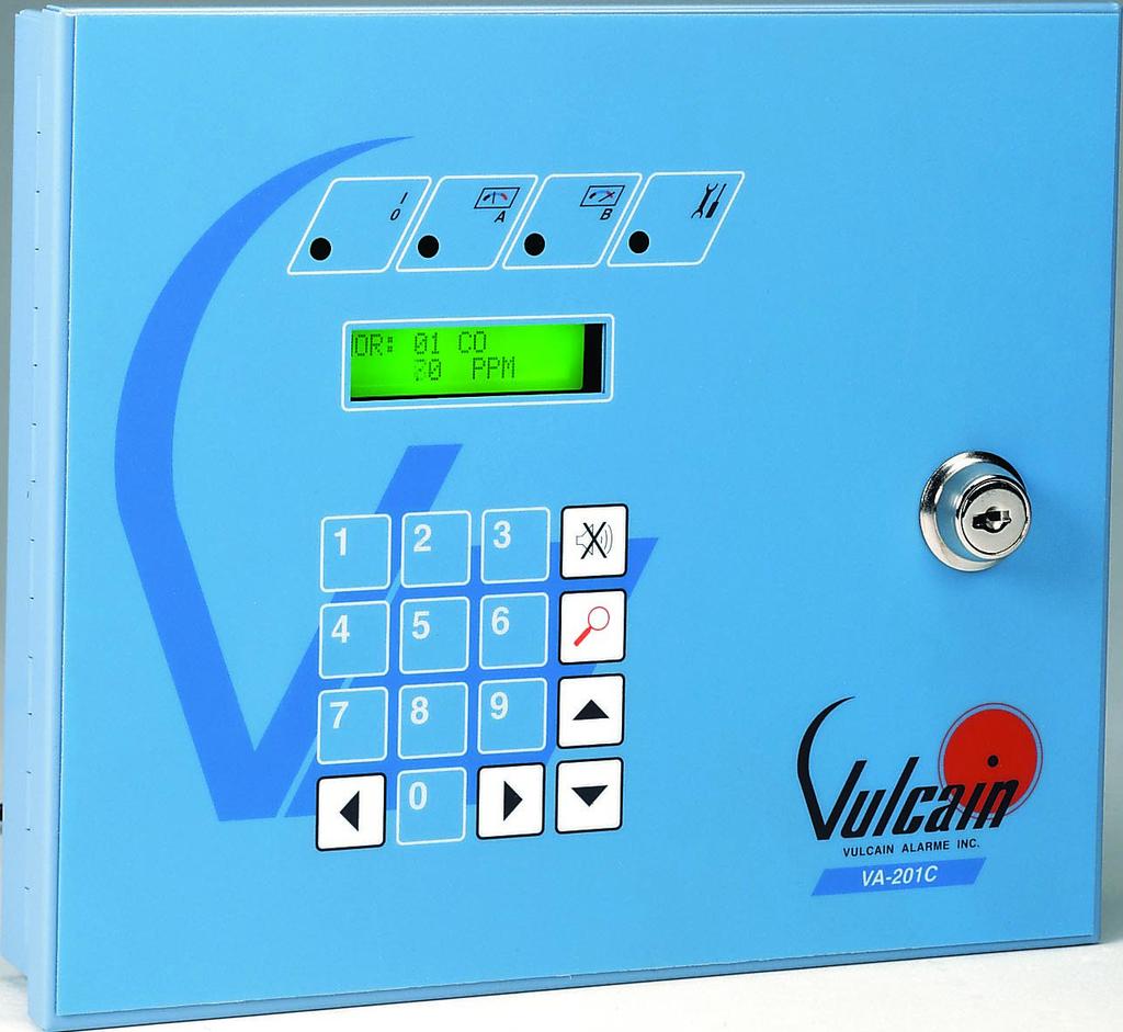
6 VA201C CONTROLLER USER INTERFACE Green LED: Power ON Red LED A and B: Indicate that one or more transmitters have reached their first (Level A) or second (Level B) alarm level. Yellow LED: Fault Display: On the first line, the first three letters indicate the status of the operation. Nor: normal or Alr: high gas concentration alarm or fault. On the same line is the transmitter address and the last 8 characters indicating the gas detected or transmitter location. Second Line Concentration read and unit of measurement Audible Alarm Silence Key KeyPad: Numbers 0-9 are used to enter the Programming Menu password. The left and right arrow keys are used to move to any of the two lines on the display. The up and down arrow keys are used to browse through the programming fields and to modify any values in a specific field. The magnifying glass is to enter or exit the Programming Menu. Each transmitter is scanned at intervals of 10 seconds. Priority of the display is given to the Alarm and Fault conditions. Up and down arrow keys allow for manual scanning of each zone. Vulcain Alarm Inc. All rights reserved 5 DR August 2004
7 SPECIFICATIONS VA201C Power Requirements: Operating Temperature Range: Operating Humidity Range: Network Capacity: User Interface: Vac, Vdc, 250 ma 32 F to 100 F (0 to 40 C) 0 to 95% RH, (non-condensing) Up to 32 transmitters, 16 per channel Optional alphanumeric display and keypad Visual Indicators: Power On Green LED Alarm Level 1 Red LED Alarm Level 2 Red LED Failure Yellow LED Audible Alarm: Outputs: Time Delays: 65dBA at 3 feet (1 metre) 3 DPDT relays 5A, 30 Vdc or 250 Vac (resistive load) 0 to 99 minutes before and after an alarm Maximum Distance Between the Controller and the Last Transmitter: 2,000 feet (600 m) Dimensions: Weight: 8.5 in(h) x 11.0 in( W)x 2.0 in(d) (22.2 cm x 26.1 cm x 5 cm) 3.5 lbs (1.58 Kg) PERIODIC INSPECTIONS AND CALIBRATION This unit requires calibration. The calibration frequency will be a function of the operating conditions, including operating under extreme temperatures, exposure to contaminants or gas concentrations greater than the lower explosive limits. A calibration inspection must be included as part of a routine maintenance to ensure proper operation of the gas detection unit. If unit span or zero cannot be adjusted, the sensor may be approaching its end-of-life or has been contaminated and must be replaced. DR August Vulcain Alarm Inc. All rights reserved
8 ELECTRICAL WIRING Output RS-232c: J5 (option) to serial printer. Power: J1 17 to 27 Vac, 24 to 38 Vdc, 250 ma. Audible Alarm Output: J2 30 ma, 12 Vdc. Power Source (Vac), Communication (A-B): J3 channel 1 et J4 channel 2. See details in tables 2, 3 and 4. Relay Output: Relay 1: J6, Relay 2: J7, Relay 3: J8, 5 A, 30 Vdc or 250 Vac (resistive load) A dédicated circuit must be used for theva201c. The electrical wire gauge is defined with respect to the network length and type of units involved. VA201TQ1 except Q1 Combustibles (Comb.) and Refrigerants (Ref.) TABLE 2 Electrical Wire Gauge Length of Network Total Number of Units per Channel per Channel ,000 feet (300 m) 18 AWG 18 AWG 16 AWG 16 AWG 1,500 feet (450 m) 18 AWG 16 AWG 16 AWG 14 AWG 2,000 feet (600 m) 18 AWG 16 AWG 14 AWG 14 AWG Vulcain Alarm Inc. All rights reserved 7 DR August 2004
9 VA301D 2, VA201TQ2, VASQNA, 90DM 3 R, VA301IRF and VA201TQ1-Exp. TABLE 3 Electrical Wire Gauge Length of Network Total Number of Units per Channel per Channel feet (225 m) 18 AWG 18 AWG 16 AWG 14 AWG 1,000 feet (300 m) 18 AWG 16 AWG 14 AWG 14 AWG 1,500 feet (450 m) 16 AWG 16 AWG 14 AWG ** 2,000 feet (600 m) 14 AWG 14 AWG ** ** ** Local power source must be used for these applications. WARNING A VA201R Relay Module will increase the total number of units per channel by 1 unit for every 2 relays. Consequently, a VA201R-8 Relay Module will increase the total number of units per channel by 4. A VA420I Module will increase the total number of units per channel by 2. The network communication wire gauge depends on the distance between the controller and the last transmitter on each communication channel. For each channel, one distinct shielded twisted pair is needed with 6 twists per foot. TABLE 4 Communication Wire Gauge Network Length per Channel Communication Wire Gauge Less than 2,000 feet (600 m) 24 AWG (Belden 9841) WARNING The communication cable must be independent from the electrical cable. A multi conductor cable is not acceptable. DR August Vulcain Alarm Inc. All rights reserved

 5A, 30Vdc or 250Vac (resistive load) 17-27 Vac, 24-38Vdc, 600mA@24Vdc")
10 VA301IRF USER INTERFACE SPECIFICATIONS Gases detected : Sensing technology: Measurement range: Resolution: Response time: Cold to start: Optional outputs: Optional audible alarm: Display : Visual indicators: Relay Output Rating: Power requirement: Operating Temperature Range: Operating Humidity Range: Enclosure: Size: Weight: R-11, R-12, R-22, R-123, R-125 and R-134a (other mixes also available) Vulcain dual infrared sensor ppm 1 ppm 60 seconds 10 minutes 4-20 ma 3 DPDT relays RS ft. Backlit LCD Green LED: Normal operation Red LEDs: Alarms A, B and C Yellow LED: Fault Yellow LED: Tx (activated in network mode) 5A, 30Vdc or 250Vac (resistive load) Vac, 24-38Vdc, 600mA@24Vdc 32 F to 100 F (0 to 40 C) 0 to 95% RH (non-condensing) ABS - Polycarbonate Transmitter 7.99 (H) x ( W) x 2.76 (D) Sensor 4.02 (H) x ( W) x 2.48 (D) Transmitter 2.26 lbs (1.02 kg) Sensor 2.33 lbs (0.603 kg) Vulcain Alarm Inc. All rights reserved 9 DR August 2004
11 ELECTRICAL WIRING - VA301IRF Power: 4-20 ma End of line: JP3 Relay Output: Input J1 Output: J5 To determine a transmitter J6, J7, J8 and output J2 See details in section to be the last in the network, 5 A, 30 Vdc 17 to 27 Vac, 4-20 ma LOOP place the jumper in an upright or 250 Vac 24 to 38 Vdc, CONFIGURATION position aligned at the top. (resistive load) 600 ma Transmitter Twisted and shielded cable #24AWG max. 100 feet (30 m). Communication: Input J10 and output J11. Vulbus protocol: Up to 16 transmitters per bus. The maximum distance between the controller and the furthest transmitter is feet. Modbus protocol: Up to 128 transmitters per bus. The maximum distance between the controller and the furthest transmitter is feet. Sensor DR August Vulcain Alarm Inc. All rights reserved
12 VA201TQ1/Q2 USER INTERFACE The 10 red LEDs indicate the gas concentration detected. Each red LED represents 10% of the reading scale. For example, an oxygen depletion transmitter with a 21% reading will have 8 red LEDs lit. When Powering ON, the green LED lights to indicate power ON. Vulcain Alarm Inc. All rights reserved 11 DR August 2004
13 SPECIFICATIONS Power Requirements: Operating Temperature Range: Operating Humidity Range: Outputs: Vac, Vdc, 250 ma 32 F to 100 F (0 to 40 C) 0 to 95% RH, (non-condensing) NH 3, 5 to 100% RH, (non-condensing) 1 DPDT optional relay 5A, 30 Vdc or 250 Vac (resistive load) 4-20 ma (optional) Maximum Distance Between the Controller and the Transmitter: 2,000 feet (600 m) Dimensions: 8.4 in(h) x 5.3 in( W) x 2.25 in(d) (21.3 cm x 13.4 cm x 5.7 cm ) DR August Vulcain Alarm Inc. All rights reserved
14 ELECTRICAL WIRING - VA201TQ1/Q2 Relay Output: J1 (optional) 5 A, 30 Vdc or 250 Vac (resistive load) 4-20 ma Output: J2 (optional) Power and Communication: J3 Fed by the VA201C controller. If the 4-20mA output is present and configurated in active mode, a local power supply is required: Vac, Vdc, 250 ma Vulcain Alarm Inc. All rights reserved 13 DR August 2004
15 VA301D 2 USER INTERFACE Menu key LCD Display Scroll key Scroll key Visual Indicators I/O (green LED) : Normal ALA (red LED) : Alarm ALB (red LED) : Alarm or fault (option) Tx : Communication F1 (yellow LED) : Sensor fault DR August Vulcain Alarm Inc. All rights reserved
16 SPECIFICATIONS Power Requirements: Vac, Vdc, Vdc Operating Temperature Range: -40 F to 100 F (-40 C to 40 C) Toxic gases -40 F to 112 F (-40 C to 50 C) Combustible gases Operating Humidity Range: 0% to 95% RH Non-condensed NH 3, 5 to 100% RH, Non-condensed) Sensing Technologies: Q1: electrochemical (toxic) catalytic combustion (combustibles) diffusion fuel cell (oxygen) Display: Visual Indicators: Alpha numeric LCD display with backlit Green LED: Normal operation Red LED: Alarm A Red LED: Alarm B Green LED: Communication Yellow LED: Fault Outputs: 4-20 ma, 2 optional SPDT fail safe relays Maximum Length of Lines: 2,000 feet (600 m) for Vulbus 4,000 feet (1,200 m) for Modbus Minimum size Conductors: See wiring requirements section Relay Output Rating: N.O.: 2a 250 Vac, 5A 125 Vca, 3A 30 Vdc N.C.: 1A 250 Vac, 2A 125 Vac, 1A 30Vdc Storage Temperature: -40 F to 112 F (-40 C to 50 C) Pressure Limits: 800 to 1200 millibars Communication: RS-485 two wires Communication Protocol: Autodetect Vulbus or Modbus Transmission Speed: 9.6 kbauds (also available: 0.3, 2.4, 19,2) Eight-bit Frame: 1 start bit, 7 bits of data, 2 stop bits, no parity 8 status bits available Enclosure: Class 1, Division 1, Groups B, C, D Dimensions: 7.5 in. (H) X 6.25 in. ( W ) X 4.5 in. (D) (19 cm x 16 cm x 11.5 cm) Weight: 4.6 lbs. (2.1 Kgs) Vulcain Alarm Inc. All rights reserved 15 DR August 2004
17 ELECTRICAL WIRING - VA301D 2 BACK Power: Input J4 and Output J8 15 to 27 Vac, 18 to 38 Vdc, Vdc. See details in table 2. Relay outputs: Relay 2, J11 5 A, 30Vdc or 250Vac (resistive load) ma loop: Output at J7 See details in table 4. Relay outputs: Relay 1, J1 5 A, 30Vdc or 250Vac (resistive load). End of line resistor: JP1 On the last transmitter of the communication network, a jumper must be installed. Communication: Input J6 and Output J3 Vulbus protocol: Up to 16 transmitters per bus. The maximum distance between the controller and the furthest transmitter is 2000 feet. Modbus protocol: Up to 128 transmitters per bus. The maximum distance between the controller and the furthest transmitter is 4000 feet. See details in table 3. DR August Vulcain Alarm Inc. All rights reserved

18 90DM 3 R USER INTERFACE During normal operation, the display will show a + and an x alternately to indicate the processor is functioning. Also shown is the transmitter address and the gas type. The gas concentration read is shown on the second line. SPECIFICATIONS Power Requirements: Operating Temperature Range: Operating Humidity Range: Vac, Vdc, 200 ma 32 F to 100 F (0 to 40 C) 0 to 95% RH (non-condensing) Maximum Distance Between the Controller and the Transmitter: 2,000 feet (600 m) Dimensions: 5.25 in(h) x 3.5 in( W) x 2.0 in(d) (11.5 cm x 7.5 cm x 4.4 cm ) Vulcain Alarm Inc. All rights reserved 17 DR August 2004
19 ELECTRICAL WIRING - 90DM 3 R Communication: Input J11 From the VA201C controller Power: Input J4 From VA201C controller If the 4-20mA output is present and configurated in active mode, a local power supply is required: 17 to 27 Vac, 24 to 38 Vdc, 200 ma Enter Key: Validation Key End of line resistor: JP1 On the last transmitter of the communication network, a jumper must be installed. Scroll Key: Browsing key in menu mode DR August Vulcain Alarm Inc. All rights reserved
20 VASQNA USER INTERFACE Green LED: Power ON Red LED A and B: Indicate that one or more transmitters have reached their first (Level A) or second (Level B) alarm level. Yellow LED: Fault Display: On the first line, the first three letters indicate the status of the operation. Nor: normal or Alr: high gas concentration alarm or fault. On the same line is the transmitter address and the last 8 characters indicating the gas detected and its unit. Second Line Concentration read and unit of measurement Keypad: The MENU key provides access to the Programming Menu and validates a choice or value. ESC key is used to quit the Programming Menu. The UP and DOWN arrow keys are used to modify a parameter or value. SPECIFICATIONS Power Requirements: Operating Temperature Range: Operating Humidity Range: Outputs: Communication (lenght of lines): Dimensions: Vac, Vdc, 200 ma 32 F to 100 F (0 to 40 C) 0 to 95% RH (non-condensing) 3 DPDT relays 5A, 30 Vdc or 250 Vac (resistive load) Up to 2,000 feet (600 m) per channel T-tap: 65 feet (20m) maximum per t-tap 130 feet (40 m) total 8.5 in (H) x 8.6 in ( W ) x 2.5 in (D) (21.3 cm x 13.4 cm x 5.7 cm ) Vulcain Alarm Inc. All rights reserved 19 DR August 2004
21 ELECTRICAL WIRING - VASQNA Power Source (vac), Communication (A-B) Channel A: J9 Input in the lower terminals and output in the upper terminals (When fed by the VA201C controller) Vac, Vdc, 250 ma Power Source (vac), Communication (A-B) Channel B: J10 Input in the lower terminals and output in the upper terminals (When fed by the VA201C controller) Relay Outputs: Relay 1: J50, Relay 2: J11 and Relay 3: J12. 5 A, 30 Vdc or 250 Vac (resistive load) DR August Vulcain Alarm Inc. All rights reserved
22 VA420I SPECIFICATIONS Power Requirements: Operating Temperature Range: Operating Humidity Range: Number of Outputs: Vac, Vdc, 500 ma 32 F to 100 F (0 to 40 C) 0 to 95% RH (non-condensing) 8 dedicated 4-20 ma outputs 1 min/max and average for 16 different transmitter Maximum Distance Between the Controller and the Transmitter: 2,000 feet (600 m) Dimensions: 8.5 in (H) x 8.6 in ( W) x 2.5 in (D) (21.3 cm x 13.4 cm x 5.7 cm ) Vulcain Alarm Inc. All rights reserved 21 DR August 2004
23 ELECTRICAL WIRING - VA420I Power and Communication: J15 Input: Lower Terminal Output: Upper Terminal J8: Pull down resistor J7: 1-2, end of line resistor 2-3, end of line RC filter resistor J12: Pull up resistor 4-20 ma Outputs: S2 to S ma outputs may be set to be Current sourcing or Loop-powered Current Sourcing: S2 to S9 jumpers at 1-2, 3-4 and 5-6 Loop-Powered: S2 to S9 jumpers at 2-3, 4-5 and 6-7 When the output reads 3.33mA, the VA420I doesn t see the corresponding transmitter. DR August Vulcain Alarm Inc. All rights reserved
 Maximum Distance Between the Controller and the Transmitter: 2,000 feet (600 m) Dimensions: 8.5 in (H) x 8.6 in ( W) x 2.5 in (D) (21.3 cm x 13.")
24 VA201R SPECIFICATIONS Power Requirements: Operating Temperature Range: Operating Humidity Range: Outputs: Vac, Vdc, 500 ma 32 F to 100 F (0 to 40 C) 0 to 95% RH (non-condensing) 2, 4 or 8 DPDT relays 5A, 30 Vdc or 250 Vac (resistive load) Maximum Distance Between the Controller and the Transmitter: 2,000 feet (600 m) Dimensions: 8.5 in (H) x 8.6 in ( W) x 2.5 in (D) (21.3 cm x 13.4 cm x 5.7 cm ) Vulcain Alarm Inc. All rights reserved 23 DR August 2004
25 ELECTRICAL WIRING - VA201R Relay Outputs: Relay 1: J1, Relay 2: J2, Relay 8: J8. 5 A, 30 Vdc or 250 Vac (resistive load) Power and Communication: J10 When fed by the VA201C controller If a dedicated power supply is needed: Vac, Vdc, 250 ma DR August Vulcain Alarm Inc. All rights reserved
 Visual Indicators I/0 Normal Operation: Green LED Alarm Level 1: First Red LED Alarm Level 2: Second Red LED Alarm Level 3: Both Red LEDs blink Failure: Yellow LED")
26 VASQN8X USER INTERFACE Audible Alarm Activates intermittently if flow loss is detected, activates for one of the alarm levels reached. (Typically set to Alarm Level C) Visual Indicators I/0 Normal Operation: Green LED Alarm Level 1: First Red LED Alarm Level 2: Second Red LED Alarm Level 3: Both Red LEDs blink Failure: Yellow LED Gas Inlet Port LCD Display The LCD display scans the concentration of the gas read in each sampling zone at an interval of 2 seconds. Sample Points LED Audible Alarm Reset Key Gas Outlet Port Programming Keys ESC: Exit a Menu Menu: Access the programming or acknowledge a programming field or value Up and Down Arrow Keys: Select a programming field or value Scan the reading at a specific sampling zone Vulcain Alarm Inc. All rights reserved 25 DR August 2004
27 SPECIFICATIONS Sensing Technology: Visual Indicators: Power Requirement: Audible Alarm: Refrigerant (infrared) Electrochemical (toxic) Catalytic Combustion (combustibles) Diffusion Fuel Cell (oxygen) Normal operation: Green LED Alarm Level 1: Red LED Alarm Level 2: Red LED Failure: Yellow LED Sample Points: Green LED 120 VAC, 2A 110 dba at 3 feet (1 meter) Number of Sample Points: Up to 8 Outputs: 3DPDT relays (3 alarm levels or 2 alarm levels and fault) RS-485 Relay Output Rating: 5A, 30 Vdc or 250 Vac (resistive load) Alarm Levels: 3 Maximum Sampling Distance: 1,100 feet (335 meters) Operating Humidity Range: 0% - 95% RH, Non-Condensing Operating Temperature Range: 32 F to 100 F (0 C to 40 C) Low temperature range available Dimensions: 19.0 in (H) x in ( W ) x 4.50 in (D) (48.26 cm x cm x cm) Weight: 22.4 lbs (10.17 kg) DR August Vulcain Alarm Inc. All rights reserved
28 ELECTRICAL WIRING Communication: Output J9 (A-B) Used only with network configuration. (See details in the VA201C and VA420I User s Manual) Connector J10: Used to power and communicate with the transmitter(s). Relay Output: Relay 1: J50 Relay 2: J11 Relay 3: J12 5 A, 30 Vdc or 250 Vac (resistive load) Power: 120 Vac, 2 A A dedicated circuit must be used for the VASQN8X. Vulcain Alarm Inc. All rights reserved 27 DR August 2004
29 SURFACE-MOUNT INSTALLATION Installation of the monitor (stand-alone) or transmitter (network) simply requires the physical mounting of the enclosure and connection of the power and output lines. TABLE 5 Recommended Height Detected Gas Relative Density Height (air = 1) CO Carbon Monoxide m (3-5 feet) from floor NO 2 * Nitrogen Dioxide 1.58 (cold) 30 cm to 1 m (1-3 feet) from ceiling H 2 Hydrogen cm (1 foot) from ceiling CL 2 Chlorine cm (1 foot) from floor NH 3 Ammonia cm (1 foot) from ceiling H 2 S Hydrogen Sulfide cm (1 foot) from floor HCL Hydrogen Chloride cm (1 foot) from floor HCN Hydrogen Cyanide cm (1 foot) from floor ETO Ethylene Oxide cm (1 foot) from floor O 2 Oxygen m (3-5 feet) from floor SO 2 Sulfur Dioxide cm (1 foot) from floor R R R22 Refrigerants cm (1 foot) from floor R R R134A 3.52 COMB Most combustibles are heavier than air, with the exception of methane, hydrogen, ethylene and acetylene. For gases that are heavier than air, sensors should be installed approximately 30 cm (1 foot) from the floor. For combustibles that are lighter than air, sensors should be installed 30 cm (1 foot) from the ceiling, close to the potential leak source. * May differ in certain applications. Hot NO 2 from the exhaust system is lighter than DR August Vulcain Alarm Inc. All rights reserved
30 DETERMINATION OF NUMBER OF SYSTEMS The number of transmitters required is determined by a unit s operational radius of surveillance. Using Table 6 below, the number of units required can be easily evaluated. Table 6 Gas Detected Radius of Surveillance Area Covered CO Carbon Monoxide 50 feet 7,854 square feet NO 2 Nitrogen Dioxide (15 metres) (707 square metres) Others 23 feet 1,662 square feet (7 metres) (154 square metres) Vulcain Alarm Inc. All rights reserved 29 DR August 2004
31 RANGE AND ALARM LEVELS TABLE 7 Range and Alarm Levels Gas Detected Range Alarm Level A Alarm Level B CO Carbon Monoxide PPM 35 PPM 200 PPM NO 2 Nitrogen Dioxide 0-10 PPM 0.72 PPM 2 PPM CL 2 Chlorine 0-15 PPM 0.5 PPM 1 PPM H 2 S Hydrogen Sulfide 0-50 PPM 10 PPM 15 PPM HCL Hydrogen Chloride 0-25 PPM 1 3 PPM 4 PPM 0-50 PPM 2 HCN Hydrogen Cyanide 0-50 PPM 5 PPM 9 PPM ETO Ethylene Oxide 0-10 PPM 1 1 PPM 5 PPM 0-20 PPM 2 O 2 Oxygen 0-25% Vol. 19.5% Vol. 22% Vol. SO 2 Sulfur Dioxide 0-10 PPM 2 PPM 5 PPM NH 3 Ammonia PPM 25 PPM 35 PPM R-123 Refrigerant Q1 0-1,000 PPM 50 PPM 500 PPM R-11 Refrigerants Q1 0-1,000 PPM 250 PPM 500 PPM R-12 Refrigerants Q2 0-2,000 PPM 1,000 PPM 1,800 PPM R-22 R-125 R134A Combustibles 0-100% LEL 25% LEL 50% LEL 1 Range for the VA301D 2 transmitter 2 Range for the others transmitters When the level of alarm has been reached, the corresponding relay will remain activated for a minimum of 59 seconds. A different alarm level may have been programmed in order to satisfy the constraint of a particular application. DR August Vulcain Alarm Inc. All rights reserved
32 PCT-1TX SINGLE-POINT SAMPLE-DRAW ALL-WEATHER HOUSING The PCT-1TX is designed to enhance the transmitter s use in environments needing Nema 4 protection or in extreme climatic conditions. The aspiration system offers the possibility of mainteance accessibility for a transmitter while air aspiration is made in out of reach areas. If a lower range of temperature operation is needed, a heating option is available in order to stabilize the temperature inside the unit. To assure steady aspiration flow on the pump, an optional flow surveillance system with strobe light is also offered. Vulcain Alarm Inc. All rights reserved 31 DR August 2004
33 DETECTION PARAMETERS Time Delay Before Alarm: Time Delay After Alarm: Table 8 Transmitter Level A Outputs Level B Outputs DR August Vulcain Alarm Inc. All rights reserved
WARRANT Y AND LIMITS OF LIABILIT Y Vulcain Inc. warrants to the original purchaser that its product, and the component parts thereof, will be free fro
 A d e v i h c r D c o n e m u WARRANT Y AND LIMITS OF LIABILIT Y Vulcain Inc. warrants to the original purchaser that its product, and the component parts thereof, will be free from defects in workmanship
Warranty Registration
 WARRANT Y AND LIMITS OF LIABILIT Y Vulcain Inc. warrants to the original purchaser that its product, and the component parts thereof, will be free from defects in workmanship and materials for a period
Warranty Registration
 WARRANT Y AND LIMITS OF LIABILIT Y Vulcain Inc. warrants to the original purchaser that its product and the component parts thereof will be free from defects in workmanship and materials for a period of
VA301C CONTROLLER WITH BACnet OPTION
 ORDERING INFORMATION VA301C Controller VA301C-DLC VA301C-DLC-BIP Gas detection controller with data logging, display and plastic housing. Gas detection controller with data logging and display, BACnet/IP
Two-Channel Gas Controller
 Two-Channel Gas Controller Specifications subject to change without notice. USA 09 Page of DESCRIPTION Highly configurable, UL 0 performance-tested and -certified, and wall-mounted gas monitor; continuously
Digital Gas Transmitters with Auxiliary Inputs & Control. PolyGard 2 DC6
 Digital Gas Transmitters with Auxiliary s & Control Specifications subject to change without notice. USA 181011 Page 1 of 5 DESCRIPTION Digital RS-485 communicating, addressable toxic and combustible gas
SPECIFICATION MODEL 5200 GAS MONITOR SYSTEM. User Instructions For The Model 5200 Gas Monitor System
 SPECIFICATION MODEL 5200 GAS MONITOR SYSTEM User Instructions For The Model 5200 Gas Monitor System To completely customize the specifications to your exact application, modifications to the following
SIL 2. Ultima X Series Gas Monitors CERTIFIED
 Ultima X Series Gas Monitors 5 Now with SIL 2 CERTIFIED Products Versatile fixed instruments provide continuous monitoring of many hazardous gases using catalytic, electrochemical, and infrared gas detection
P R O D U C T S P E C I F I C A T I O N MSA Ultima X Series Sensor/Transmitter Specification
 P R O D U C T S P E C I F I C A T I O N MSA Ultima X Series Sensor/Transmitter Specification 1.0 This specification details the attributes and operating characteristics of the MSA Ultima X Series sensors/transmitters.
EXAMPLES OF HOW TO ORDER
 E 3 Point PRODUCT SUBMITTAL Toxic and Combustible Gas Detector Standalone Platform (Single or Dual-Gas Monitoring) ORDERING INFORMATION Single-Gas or Dual-Gas Configuration: Base Unit, Surface-Mount Base
EXAMPLES OF HOW TO ORDER
 E 3 Point PRODUCT SUBMITTAL Toxic and Combustible Gas Detector Standalone Platform (Single or Dual-Gas Monitoring) ORDERING INFORMATION Single-Gas or Dual-Gas Configuration: Base Unit, Surface-Mount Base
Nitrogen Dioxide (NO2) Single-Point Gas Detection System
 Single-Point Gas Detection System") Nitrogen Dioxide (NO) Single-Point Gas Detection System DESCRIPTION Wall-mounted gas monitor with built-in nitrogen dioxide (NO)/diesel fume gas sensor, accepts one analog remote device such as a secondary
Nitrogen Dioxide (NO) Single-Point Gas Detection System DESCRIPTION Wall-mounted gas monitor with built-in nitrogen dioxide (NO)/diesel fume gas sensor, accepts one analog remote device such as a secondary
5New features & EXtreme design, now with HART Protocol and DuraSource Technology. Ultima X Series Gas Monitors
 Ultima X Series Gas Monitors Versatile fixed instruments provide continuous monitoring of many hazardous gases using catalytic, electrochemical, and infrared gas detection methods. HART Protocol is now
Self-contained and intrinsically safe wireless stand-alone multi-point gas detector.
 Introduction United Safety applies the detection system as a multi-point monitoring for toxic gases, combustibles and oxygen hazards. Self-powered and solar-capable, the features unequaled versatility,
Oxygen (O2) Single-Point Gas Detection System
 Single-Point Gas Detection System") Oxygen (O) Single-Point Gas Detection System DESCRIPTION Wall-mounted gas monitor with built-in oxygen (O) sensor, accepts one analog remote device such as a secondary gas sensor, temperature or humidity
Oxygen (O) Single-Point Gas Detection System DESCRIPTION Wall-mounted gas monitor with built-in oxygen (O) sensor, accepts one analog remote device such as a secondary gas sensor, temperature or humidity
Toxic Gas Detection. Model F12. Toxic Gas Detection
 Toxic Gas Detection Model F12 Toxic Gas Detection Smart Sensor Technology The Series F12 Gas Transmitter is an Intrinsically Safe (IS) version of our explosion-proof D12 transmitter. In its standard form,
Carbon Monoxide Transmitter
 Introduction The CO Transmitter uses an electrochemical sensor to monitor the carbon monoxide level and outputs a field-selectable 4-20 ma or voltage signal. The voltage signal may also be set to 0-5 or
GG-2 2-CHANNEL GAS DETECTION CONTROL PANEL. Installation and Operation Manual
 GG-2 2-CHANNEL GAS DETECTION CONTROL PANEL Installation and Operation Manual 2 GG-2 Warning Use this product only in the manner described in this manual. If the equipment is used in a manner not specified
Macurco DVP-120 Detection and Ventilation Control Panel
 Macurco DVP-120 Detection and Ventilation Control Panel User Instructions IMPORTANT: Keep these User Instructions for reference. TABLE OF CONTENTS 1 Introduction 4 1.1 General Information 4 1.2 Features
INSTALLATION AND OPERATING INSTRUCTIONS
 INSTALLATI AND OPERATING INSTRUCTIS PRODUCTS CMD Series CO Detectors FGD Series Refrigerant Detectors AGD Series Toxic Gas Detectors CGD Series Combustible Gas Detectors (All transmitters are factory set
Macurco DVP-120 / DVP-120M Detection and Ventilation Control Panel User Instructions
 Macurco DVP-120 / DVP-120M Detection and Ventilation Control Panel User Instructions IMPORTANT: Keep these User Instructions for reference. TABLE OF CONTENTS 1 Introduction 4 1.1 DVP-120 General Information
Inc Series Digital Gas Detector/Controller. Operation Manual
 5 Series Digital Gas Detector/Controller Operation Manual TABLE OF CONTENTS 1. 2. 3. 4. 5. 6. 7. General Description 1.1 Applications 1.2 Features Model Selection Guide Characteristics Installation 4.1
EAGLE 2. 6 Channel Capacity. Inlet fitting. Loud buzzer (95dB) IrDA communication port Low flow shutoff and alarm Alarm LED s with wide visibility
 IrDA communication port Low flow shutoff and alarm Alarm LED s with wide visibility") EAGLE 2 Inlet fitting Loud buzzer (95dB) IrDA communication port Low flow shutoff and alarm Alarm LED s with wide visibility Internal / external hydrophobic filters Self healing polyurethane protective
EAGLE 2 Inlet fitting Loud buzzer (95dB) IrDA communication port Low flow shutoff and alarm Alarm LED s with wide visibility Internal / external hydrophobic filters Self healing polyurethane protective
Combustible Gas Detection and Control System
 Combustible Gas Detection and Control System DESCRIPTION Gas monitor with built-in combustible gas sensor, wall-mounted, accepts inputs from remote devices such as other gas sensors, temperature or humidity
GASGUARDIAN Channel Controller OPERATING & INSTALLATION MANUAL
 GASGUARDIAN 2 3 2-Channel Controller OPERATING & INSTALLATION MANUAL GasGuardian 2 3 Operating and Installation Manual Table of Contents General description.... 3 Installation. 3 Locating the GasGuardian-2..
Sieger Apex. Flexibility that meets your requirements
 Sieger Apex Flexibility that meets your requirements Sieger Apex Easy to Install Sensor can be remotely mounted up to 100m from the transmitter On board relays allow for local audible/ visual alarms Strong
Universal Gas Detector
 Universal Gas Detector Instruction Manual PureAire Monitoring Systems, Inc. 557 Capital Drive Lake Zurich, Illinois 60047 Phone: 847-726-6000 Fax: 847-726-6051 Toll-Free: 888-788-8050 pureairemonitoring.com
Model D12-IR. Digital Gas Transmitter...
 Model D12-IR Digital Gas Transmitter... ATI s Series D12 gas transmitter line now includes a versatile Infrared system that can be configured for LEL or select toxic gases. The D12-IR utilizes a compact
Version Inc Series Digital Gas Detector/Controller. Operation Manual
 6000 Series Digital Gas Detector/Controller Version 000.02 Operation Manual TABLE OF CONTENTS 1.0 2.0 3.0 4.0 5.0 6.0 General Description 1.1 Applications 1.2 Features 1.3 Outputs 1.4 User Interface Model
4-20mA CYBER Cyber Transmitter for flammable, toxic and IR gas detection Cyber Head Increased security in ATEX certified head
 4-20mA CYBER Cyber Transmitter for flammable, toxic and IR gas detection Cyber Head Increased security in ATEX certified head NET DRAFT version 2.1-2008 Pag. 1 4-20mA Cyber - DRAFT version 2.1-2008 Pag.
Operation Manual. Rev. E GEM-II Self Contained Gas Detector.
 Operation Manual Rev. E 2014.10 GEM-II Self Contained Gas Detector www.critical-environment.com GEM-II - Operation Manual Rev. E 2014.10 Table of Contents 1 POLICIES... 5 1.1 Important Note...5 1.2 Warranty
GLD-30 Gas Leak Detector
 GLD-30 Gas Leak Detector Installation, Operation & Maintenance General: The Archer Instruments GLD-30 is an ambient air monitor, used to detect the presence of a target gas (or gases) and to alert operators
Carbon Monoxide (CO) Gas Detectors with (0)2-10 Vdc or (0)4-20 ma Output
 Gas Detectors with (0)2-10 Vdc or (0)4-20 ma Output") Features Electrochemical sensor element (0)2-10 Vdc or (0)4-20 ma output, jumper selectable Standard IP65 plastic enclosure Measuring ranges 0-50 ppm 0-100 ppm 0-150 ppm 0-200 ppm 0-250 ppm 0-300 ppm 0-500
Features Electrochemical sensor element (0)2-10 Vdc or (0)4-20 ma output, jumper selectable Standard IP65 plastic enclosure Measuring ranges 0-50 ppm 0-100 ppm 0-150 ppm 0-200 ppm 0-250 ppm 0-300 ppm 0-500
Controllers. Instruction Manual WARNING
 Controllers Instruction Manual WARNING THIS MANUAL MUST BE CAREFULLY READ BY ALL INDIVIDUALS WHO HAVE OR WILL HAVE THE RESPONSIBILITY FOR INSTALLING, USING OR SERVICING THIS PRODUCT. Like any piece of
Operation Manual. Rev. D GEM-II Self-Contained Gas Detector.
 Operation Manual Rev. D 2012.04 GEM-II Self-Contained Gas Detector www.critical-environment.com Rev. D 2012.04 GEM-II Operation Manual TABLE OF CONTENTS 1 POLICIES... 5 1.1 Important Note... 5 1.2 Warranty
Model D12. Digital Gas Transmitter
 Model D12 Digital Gas Transmitter Gas detection systems come in all shapes and sizes. Some require simple 4-20 ma transmission. Some are better suited to local alarm relay functions. Some really require
OLC(T) 100 FIXED GAS DETECTOR
 100 FIXED GAS DETECTOR") Fixed Gas Detector OLC(T) FIXED GAS DETECTOR Detection of explosive gases, toxic gases or oxygen Infrared XP version SIL 2 high reliability IP 66 Aluminium or Stainless Steel version CERTIFICATIONS The
Fixed Gas Detector OLC(T) FIXED GAS DETECTOR Detection of explosive gases, toxic gases or oxygen Infrared XP version SIL 2 high reliability IP 66 Aluminium or Stainless Steel version CERTIFICATIONS The
FIXED POINT SINGLE OR DUAL GAS MONITOR WITH DUAL ANALOG OUTPUTS
 USER MANUAL itrans 2 FIXED POINT SINGLE OR DUAL GAS MONITOR WITH DUAL ANALOG OUTPUTS Part Number: 77036429-EN Version: 1.1 Copyright 2013 by Oldham S.A.S All rights reserved. No reproduction of all or
Mark 25 Ultrapure Water Conductivity Analyzer
 Martek Instruments, Inc. Mark 25 Ultrapure Water Conductivity Analyzer Instruction Manual WARRANTY POLICY Unless otherwise stated, MARTEK INSTRUMENTS, INC. warrants this equipment to be free from defects
Detection of explosive gases, toxic gases or oxygen. Infrared XP version. SIL 2 high reliability IP 66. Certifications. The Fixed Gas Detection People
 Fixed Gas Detector Detection of explosive gases, toxic gases or oxygen Infrared XP version SIL 2 high reliability IP 66 Certifications The Fixed Gas Detection People The OLC/OLCT CT range of fixed ddetectors
REMOTE TOXIC, COMBUSTIBLE, AND OXYGEN GAS SENSORS WITH LOCAL DIGITAL DISPLAY
 REMOTE TOXIC, COMBUSTIBLE, AND OXYGEN GAS SENSORS WITH LOCAL DIGITAL DISPLAY FEATURES TXGARD & FLAMGARD PLUS Digital display with flexible output options Wide range of long life sensors Non-intrusive one-man
QAS-101 SERIES SINGLE CHANNEL CONTROLLERS
 QAS-101 SERIES SINGLE CHANNEL CONTROLLERS INSTALLATION OPERATION AND MAINTENANCE MANUAL QUATROSENSE ENVIRONMENTAL LTD. 5935 OTTAWA STREET, PO BOX 749, RICHMOND, ONTARIO, CANADA. K0A 2Z0 PHONE: (613) 838-4005
Gas Detection System TOX ALARM DG2000-Garage
 Gas Detection System TOX ALARM DG2000-Garage Gas Detection System 32 independent programmable channels 2 programmable alarm levels for each gas = up to 6 for each channel LCD alphanumeric display of gas
3years. Detection of explosive gases, toxic gases and oxygen. Infrared XP IR version. SIL 2 high reliability IP 66.
 Fixed Gas Monitoring Solutions Detection of explosive gases, toxic gases and oxygen Infrared XP IR version SIL 2 high reliability IP 66 E n o r t c e l i c 3years W a r r a t n y Certifications: The Fixed
MODEL QTS-1800 SERIES WALL MOUNT DIGITAL AND ANALOG TRANSMITTER/SENSOR
 MODEL QTS-1800 SERIES WALL MOUNT DIGITAL AND ANALOG TRANSMITTER/SENSOR INSTALLATION OPERATION AND MAINTENANCE MANUAL QUATROSENSE ENVIRONMENTAL LTD. 5935 OTTAWA STREET, PO BOX 749 RICHMOND, ONTARIO CANADA
incontrol Systems Inc. Flame and Gas Detection
 incontrol Systems Inc. Flame and Gas Detection Our flame and gas detectors are globally certified to the latest product approval standards Wherever toxic or combustible gases are part of an industrial
ULTIMA XL/XT Series Gas Monitors. [ Ultimate Features Extreme Design ]
![ULTIMA XL/XT Series Gas Monitors. [ Ultimate Features Extreme Design ]](/thumbs/81/83177381.jpg "ULTIMA XL/XT Series Gas Monitors. [ Ultimate Features Extreme Design ]") ULTIMA XL/XT Series Gas Monitors [ Ultimate Features Extreme Design ] Cost effective fixed installation gas monitors with HART Field Communications Protocol. Single-sensor units use catalytic, electrochemical
ULTIMA XL/XT Series Gas Monitors [ Ultimate Features Extreme Design ] Cost effective fixed installation gas monitors with HART Field Communications Protocol. Single-sensor units use catalytic, electrochemical
Instruction Manual WARNING
 Controllers Instruction Manual WARNING THIS MANAUL MUST BE CAREFULLY READ BY ALL INDIVIDUALS WHO HAVE OR WILL HAVE THE RESPONSIBILITY FOR INSTALLING, USING OR SERVICING THIS PRODUCT. Like any piece of
Universal Transmitter. Operations & Maintenance Manual
 Universal Transmitter Operations & Maintenance Manual Version: 080423 (724) 489-8450; Fax: (724) 489-9772 Page 1 of 21 http://www.conspec-controls.com Warranty & Disclaimer Information 6 Guttman Boulevard,
User Manual. PolyGard CO LC-1112 V3. Electrochemical analog carbon monoxide transmitters serial no. EC-S 002. August 29, 2006
 PolyGard CO LC-1112 V3 Electrochemical analog carbon monoxide transmitters serial no. EC-S 002 User Manual August 29, 2006 January 04, 2016 Revision Specifications subject to change without notice. USA
MODEL 4300-PG CENTRAL ACCESS PANEL FOR EC-GOLD TRANSMITTERS. User Manual
 MODEL 4300-PG CENTRAL ACCESS PANEL FOR EC-GOLD TRANSMITTERS User Manual Technical Support Continental North America Toll Free 1-(800) 387-9487 Ph: +1 (905) 829-2418 Fx: +1 (905) 829-4701 A Product of Arjay
QAS SERIES PLUG-IN CONTROLLERS c/w SOLID STATE SENSOR
 QAS-10000 SERIES PLUG-IN CONTROLLERS c/w SOLID STATE SENSOR INSTALLATION, OPERATION AND MAINTENANCE MANUAL QUATROSENSE ENVIRONMENTAL LTD. 5935 OTTAWA STREET, PO BOX 749, RICHMOND, ONTARIO, CANADA. K0A
GasSens. Self Checking Gas Sensors. Modular Gas Detector... Gas & Range Availability
 GasSens Modular Gas Detector... Self Checking Gas Sensors GasSens is a flexible component system providing a variety of options to meet individual gas detection and alarm requirements. From chemical and
User Manual. PolyGard Gas Controller MGC3. Two-Channel Analog Gas Controller Serial Number _E _0907. September 2007
 PolyGard Gas Controller MGC3 Two-Channel Analog Gas Controller Serial Number _E _0907 User Manual September 2007 January 04, 2016 Revision Specifications subject to change without notice. USA 160104 Page
ALTAIR 5X Multigas Detector Product Specification
 ALTAIR 5X Multigas Detector Product Specification PHYSICAL CHARACTERISTICS Gas delivery Size, pumped unit without IR Size, pumped unit with IR Weight Handling Case material Environmental protection Display
3M Oldham OLCT 100. Description. Fixed Gas Detector
 Fixed Gas Detector Description The OLC/OLCT range of fixed detectors has been designed for detection of combustible gases, toxic gases or oxygen. Available in explosion-proof or intrinsically safe versions,
IMR IX176 Portable Gas Detector User Manual
 IMR Portable Gas Detector User Manual Read this manual carefully before using this device. (727) 328-2818 / (800) RING-IMR Fax: (727) 328-2826 www.imrusa.com Ver. 1.0A4 CONTENTS SERVICE GUIDELINES... 3
IGD.CO.UK
 APPLICATION DATA SHEET S p e c i f i c a t i o n 2 SO22 WWW.-..UK Control Systems Transmitters Sensors Accessories TOCSIN 700+ D e t e c t o r Website: C o n t r o l P a n e l - Wall mounting or 19 Rack
GG-H2S HYDROGEN SULFIDE GAS SENSOR. Installation and Operation Manual
 GG-H2S HYDROGEN SULFIDE GAS SENSOR Installation and Operation Manual 2 GG-H2S Warning Use this product only in the manner described in this manual. If the equipment is used in a manner not specified by
Stand Alone DYNAGARD SP Operation Manual
 Stand Alone DYNAGARD SP Operation Manual Contents Page General Description 1 Detection Principle 1 For Your Safety 1 Design 2 Mounting 2 Mounting Position of DYNAGARD SP 2 Installation of Electrical Connections
GL-CO-RFG Channel Gas Leak Alarm System
 Four Elms Road Edenbridge Kent TN8 6AB UK Features & Benefits Remote sensors for natural gas, LPG and CO 1 x SPST relay outputs DIN-rail as standard, panel mounting kit available Adjustable alarm thresholds
Detection of explosive gases, toxic gases or oxygen. Infrared XP version. SIL 2 high reliability IP 66. Aluminium or Stainless Steel version
 Fixed Gas Detector Detection of explosive gases, toxic gases or oxygen Infrared XP version SIL 2 high reliability IP 66 Aluminium or Stainless Steel version Certifications Pending The Fixed Gas Detection
PureAire Combo O 2 / CO 2 Monitor
 PureAire Combo O 2 / CO 2 Monitor Instruction Manual PureAire Monitoring Systems, Inc. 557 Capital Drive Lake Zurich, Illinois 60047 Phone: 847-726-6000 Fax: 847-726-6051 Toll-Free: 888-788-8050 pureairemonitoring.com
SEC 2000 Millenium Infrared Gas Detector
 SEC 2000 Millenium Infrared Gas Detector Instruction and Operation Manual Sensor Electronics Corporation 5500 Lincoln Drive Minneapolis, Minnesota 55436 USA (952) 938-9486 Fax (952) 938-9617 Email: sales@sensorelectronic.com
Sieger Sensepoint. Easy to Use Factory set operation Simple to replace Minimal training required
 Sieger Sensepoint The Sensepoint range of flammable, toxic and oxygen gas detectors offer users a high quality, low cost solution to their industrial gas monitoring needs. Sieger Sensepoint Fit For Purpose
Frequently Asked Questions
 1. 2. What advantages does the GT3000 have over the C7064? Hot swappable GTS sensor module is intrinsically safe and allows live maintenance under power Supports HART communication Supports local, one-person
Toxic and Explosive Smart Gas Monitor PN / Installation and User Manual
 Toxic and Explosive Smart Gas Monitor PN 151022/151023 Installation and User Manual Quest Controls, Inc. 208 9 th Street Dr. West Palmetto, FL 34221 www.questcontrols.com Phone: (941) 729-4799 Fax: (941)
PointGard II. Operating Manual
 PointGard II Operating Manual For Your Safety For Your Safety Strictly follow the assembly and installation instructions The instrument must be calibrated at intervals recommended in the operating manual
FIXED POINT SINGLE OR DUAL GAS MONITOR WITH DUAL ANALOG OUTPUTS
 USER MANUAL itrans 2 FIXED POINT SINGLE OR DUAL GAS MONITOR WITH DUAL ANALOG OUTPUTS Part Number: 77036429-EN Version: 4.0 The Fixed Gas Detection Experts Copyright January 2017 by Oldham S.A.S All rights
User and Installation manual
 Toxic, explosive and oxygen gas detection control panel User and Installation manual FS82426 2018 DURAN ELECTRONICA S.L. - All rights reserved www.duranelectronica.com RANGE OF COMPATIBLE PRODUCTS Remote
AMC-RAM-4. Refrigerant Alarm Module USER MANUAL. Please read the installation and operating instructions completely and carefully before starting.
 AMC-RAM-4 Refrigerant Alarm Module USER MANUAL IMPORTANT: Please read the installation and operating instructions completely and carefully before starting. Filename: 3310405B, DOC, AMC_RAM4_Manual.doc
5 Operating Modes GX Smallest 6 gas sample draw PID library of over 600 VOC s 2 Interchangable smart sensor slots
 5 Operating Modes GX-6000 Smallest 6 gas sample draw PID library of over 600 VOC s 2 Interchangable smart sensor slots GX-6000 5 Operating modes Normal Leak Check Inert Bar hole Snap Log Monitor up to
5 Operating Modes GX Smallest 6 gas sample draw PID library of over 600 VOC s 2 Interchangable smart sensor slots
 5 Operating Modes GX-6000 Smallest 6 gas sample draw PID library of over 600 VOC s 2 Interchangable smart sensor slots CONFINED SPACE ENTRY Monitor LEL, O2, CO, and H2S Internal sample pump Pull samples
GAS MONITOR Model Model
 Sierra Monitor Corporation 1991 Tarob Court, Milpitas, CA 95035 (408) 262-6611 (800) 727-4377 (408) 262-9042 - Fax E-mail: sierra@sierramonitor.com Web Site: www.sierramonitor.com GAS MONITOR Model 2350-00
GASGUARD NH 3. Ammonia Sensor OPERATING & INSTALLATION MANUAL
 GASGUARD NH 3 Ammonia Sensor OPERATING & INSTALLATION MANUAL Operating and Installation Manual 2 Table of Contents GasGuard NH 3 Operating and Instruction Manual General description. 4 Installation.. 4
Air Check O 2 Deficiency Monitor 0-25%
 Air Check O 2 Deficiency Monitor 0-25% Instruction Manual RS-485 Revision 4.05 Part number 99066 PureAire Monitoring Systems, Inc. 557 Capital Drive Lake Zurich, Illinois 60047 Phone: 847-726-6000 Fax:
GAS DETECTION MANUFACTURED BY. Aerionics, Inc. Sioux Falls, SD Phone:
 CM-1 CO ppm MANUFACTURED BY Aerionics, Inc. Sioux Falls, SD Phone: 1-877-367-7891 Email: info@aerionicsinc.com www.macurco.com Detectors for use with Fire and Security Systems The Macurco CM-E1, GD-2B,
! "! # Please read these installation and operating instructions completely and carefully before starting.
 ! "! # $% Please read these installation and operating instructions completely and carefully before starting. File name:3009405d Revised,20/10/2008 Copyright, July 2004 The Armstrong Monitoring Corporation
RAM3 Remote Alarm Module
 RAM3 Remote Alarm Module INSTRUCTIONS Installation and Operation of the AMC-RAM3 with AMC Monitors IMPORTANT: Please read this installation and operating instructions completely and carefully before starting.
Danfoss gas detection units
 Data sheet Danfoss gas detection units Types GD Premium, Premium+, Premium Duplex, Premium Remote, Premium Flex and Premium Uptime The Premium line gas detection units are used for monitoring and warning
TOXIC GAS AND OXYGEN DETECTOR DTX 420 INSTALLATION, OPERATING AND MAINTENANCE INSTRUCTIONS DTX420_MAN01_EN_V1R2
 TOXIC GAS AND OXYGEN DETECTOR INSTALLATION, OPERATING AND MAINTENANCE INSTRUCTIONS DTX420_MAN01_EN_V1R2 1 Introduction These instructions must be read carefully by any person who has or will have the responsibility
GASGUARD H 2-1% Hydrogen Sensor OPERATING & INSTALLATION MANUAL
 GASGUARD H 2-1% Hydrogen Sensor OPERATING & INSTALLATION MANUAL 2 Table of Contents GasGuard H 2-1% General description. 4 Installation.. 4 Locating the sensor. 4 Installation guidelines 5 Wiring.. 6 Operation..
CMF, CMX & CMA series
 Features Electrochemical sensor element 4-20 ma or 2-10 Vdc output CMF- IP 44 protection CMX- IP 54 protection CMA- IP 65 protection Wide supply voltage range (18-28 Vdc) Overload and short cicuit protected
HALOGUARD IR MULTI-POINT, COMPOUND SPECIFIC MONITOR INSTRUCTION MANUAL
 HALOGUARD IR MULTI-POINT, COMPOUND SPECIFIC MONITOR INSTRUCTION MANUAL S E R I A L N O. M O D E L N O. T e m p. R a n g e 1 - = > 6 0 o F 2 - = 4 0-6 0 o F 3 - = < 4 0 o F - G a s T y p e 1 - R -1 1 2
Murco Core Product Guide Gas Leak Detection Solutions for all your building needs
 Murco Core Product Guide Gas Leak Detection Solutions for all your building needs Refrigerant Gases Toxic Gases Combustible Gases VOC s Legislation: F Gas Regulation, EH40 Standards: EN378 Lloyds Approval
OLCT 700 & 710. Certifications FIXED GAS DETECTION. Better detection. Better protection.
 FIXED GAS DETECTION OLCT 700 Series OLCT 700/710 industrial gas detection sensors are a new generation of intelligent sensor modules that incorporate and integrate several leading edge improvements. &
Detectors-Transmitters for Flammable, Toxic Gases and Oxygen. Non-intrusive operation via intrinsically safe infrared remote control.
 Détecteur de gaz OLCT80 Detectors-Transmitters for Flammable, Toxic Gases and Oxygen Non-intrusive operation via intrinsically safe infrared remote control Disponible en version déportée, ADF ou de SI
Analog Room Pressure Monitor RPC Series
 Description The Room Pressure Monitor is used to measure differential pressure in the range of 0.125 to 1"wc or 30 to 250 Pa. It combines precision high sensitivity silicon sensing capabilities and the
OLCT 100 DETECTION DE GAZ FIXE. Certifications. Better detection. Better protection. Detection of Combustible, Toxic or Oxygen gases
 DETECTION DE GAZ FIXE OLCT Detection of Combustible, Toxic or Oxygen gases Infrared XP version SIL 2 high reliability IP 66 Aluminium or Stainless Steel version Certifications Better detection. Better
Macurco HD-11 Hydrogen Gas Detector
 Macurco HD-11 Hydrogen Gas Detector User Instructions Important: Keep these User Instructions for reference TABLE OF CONTENTS GENERAL SAFETY INFORMATION 3 Intended Use 3 List of Warnings and Cautions 3
21-light Remote Annunciator. Owner s Manual
 21-light Remote Annunciator Owner s Manual Annunciator Description... Inside Font Cover Detailed Specifications... 1 Environmental Specifications... 1 Power Supply Requirements... 1 Communication With
CH 4 C 2 H 2 C 3 H 8 CO 2 H 2 H 2 S HFC NH 3 NO 2 O 2 O 3 SO 2
 PluraSens CH 4 C 2 H 2 C 3 H 8 CO CO 2 H 2 H 2 S HFC NH 3 NO 2 O 2 O 3 SO 2 VOC E2600 Family Gas Detectors E2610 Series Compact wall-mount housing providing optimal airflow Integrated sensor with long
GAS PLUS ALARM SYSTEM
 GAS PLUS -IR SERIES 4688-IR COMBUSTIBLE GAS OR CARBON DIOXIDE TRANSMITTER GAS PLUS -IR TRANSMITTER SERIES 4688-IR COMBUSTIBLE GAS OR CARBON DIOXIDE TRANSMITTER The Scott Gas Plus -IR Model 4688 IR Gas
Dependable Solutions for Gas Detection
 Dependable Solutions for Gas Detection Combustibles/Flammables Standard & Exotic Toxics Oxygen Enrichment/Deficiency Introduction to Sensidyne Established in 1983 - acquired by Schauenburg GmbH in April
QD6310. Fixed Gas Detector Operation Manual
 QD6310 Fixed Gas Detector Operation Manual Safety Information Before using the device, please first carefully read and follow the following information to operate the device: Please don't use the defective
GasScanner 4C. Four Channel Monitor. Operator s Manual. MINT-0280-XX Rev. A 02/25/08
 GasScanner 4C Four Channel Monitor Operator s Manual MINT-0280-XX Rev. A 02/25/08 Product Warranty Matheson Tri-Gas., warrants gas alarm equipment sold by us to be free from defects in materials, workmanship,
Pioneer-R16 Gas Monitor Operator s Manual
 Pioneer-R16 Gas Monitor Operator s Manual Edition 7/2/97 RKI INSTRUMENTS, INC RKI Instruments, Inc. 33248 Central Ave, Union City, CA 94587 (510) 441-5656 Chapter 1: Description About the Pioneer-R16 Gas
Air Check O 2 Sample Draw Monitor
 Air Check O 2 Sample Draw Monitor Instruction Manual PureAire Monitoring Systems, Inc. 557 Capital Drive Lake Zurich, Illinois 60047 Phone: 847-726-6000 Fax: 847-726-6051 Toll-Free: 888-788-8050 pureairemonitoring.com
Danfoss gas detection unit Type GD Heavy Duty
 Data sheet Danfoss gas detection unit Type GD Heavy Duty The Heavy Duty gas detection units are used for monitoring and warning of hazardous Ammonia gas concentrations. They are intended for ATEX/ IECEx
M3050 Detector Operator s Manual
 FABRICON SYSTEMS ALBERTA 2008 INC. Keeping you in Front M3050 Detector Operator s Manual Telephone: (403)652-2127 Mailing Address: Shipping Address: Fax: (403)652-3027 Box 5996 402 Ellis Crescent S.E Email: