Installation and Programming Manual
|
|
|
- Diane Dixon
- 5 years ago
- Views:
Transcription

1 Installation and Programming Manual
2
3 Installation and Programming Manual (Ver 4.31 and above)
4
5 Table of Contents Chapter 1: Introducing WisDom What is the WisDom? WisDom Architecture and Capabilities WisDom Features Technical Specifications Chapter 2: Installing the WisDom WisDom Installation Steps WisDom Components Mounting the WisDom Choosing the mounting location Wall Mounting the WisDom Wiring the WisDom Connecting AC Power Connecting the Telephones Lines Wiring the Bell Tamper Wiring the Programming Outputs Wiring an External Sounder Ground Connection Wiring the Hardwire Zone Connecting the Backup Battery Auxiliary Terminal Wired Expansion Bus Modules (Optional) Jumpers Setting Adjusting the LCD Contrast Chapter 3: Programming the WisDom WisDom Programming Options Using the WisDom s LEDs and Keys Engineer Programming from the WisDom Keys Accessing the Engineer Programming Menu Restoring Manufacturer's Programming Defaults Keypad Timeout Using the Program Transfer Module (PTM) Chapter 4: Using the Engineer Programming Menus Engineer Programming Menu Conventions System System: Timers System: Parameters System: Receiver System: Clock System: Labels System: Sound WisDom Installation and Programming Manual i
6 System: Defaults System: Service Information System: Version Zones Zones: Allocation Zones: Parameters Zones: Testing Zones: Editing Zones: Crossing Zones: Alarm Confirmation Programmable Outputs Programmable Outputs: Define Programmable Outputs: Output A Programmable Outputs: Output B Code Maintenance Codes: Authority Codes: Partition Codes: Grand Master Codes: Engineer Codes: Sub-Engineer Codes: Code Length Digicom Digicom: ARC Link - Up Digicom: Customer Account Numbers Digicom: ARC Communication Format Digicom: U/D Telephone Number Digicom: U/D Access and ID Digicom: Controls Digicom: Parameters Digicom: ARC Report Split Digicom: Follow-Me Report Codes Report Codes: Auto Codes Report Codes: Manual Codes Alarm Receiving Station: Voice Alarm Verification Key-fobs Key-fobs: Allocation Key-fob: Parameters Key-fob: Communication Test Keypads Keypads: Allocation Keypads: Communication Test More Devices More Devices: GSM ii WisDom Installation and Programming Manual
7 More Devices: Sounder More Devices: X Exit Programming Chapter 5: Engineer Programming Within the User Programming Menu User Authorization for Engineer Programming Programming the Voice Messages Voice Messages Types Message Structure Voice Message Labels Test Message Local Announcement Messages Walk Test Replacing Backup Batteries Appendix A: Report Codes...A-1 Report Code Programming for SESCOA SUPERFAST (03B1)...A-1 Report Code Programming for ADEMCO POINT (CONTACT) ID (0420)...A-2 Report Code Programming for SIA (0700)...A-3 Appendix B: Event Log Messages...B-1 Appendix C: EN50131 Default Values...C-1 Appendix D: WisDom Accessories...D-1 WisDom Installation and Programming Manual iii
8 iv WisDom Installation and Programming Manual
9 Chapter 1: Introducing WisDom This chapter provides a basic introduction to the WisDom system, its architecture and capabilities, as described in the following sections: What is the WisDom? below WisDom Architecture and Capabilities, page 1-2 WisDom Features, page 1-3 Technical Specifications, page 1-3 What is the WisDom? The WisDom is a fully featured wireless security system, providing sophisticated solutions for alerting and reporting premises alarm signals. The WisDom has been specifically designed to meet a wide range of security needs of homes, offices and small commercial applications. The WisDom is simple and fast to install. It has a user friendly interface that enables easy installation, programming and use. In addition, the WisDom can also be programmed and/or controlled through local or remote Upload/Download software installed on a PC computer with a Windows operating system. It has a built in sounder and it is designed around microprocessor and EEPROM (Electrically Erasable Programmable Read-Only Memory) technology, which stores the system's operating program, as well as its programmable parameters, without dependency on external power sources. The WisDom is available in MHz Radio Frequency. The WisDom main benefits are: Engineer Benefits: Simple programming logic fully menu driven Wireless calibration and adjustable threshold level, enables higher false alarm immunity. Actual transmitter signal strength and RF noise displayed on LCD, eliminating the need for an external strength meter. All detectors supervised for presence, low battery, jamming and tamper Supports all major central station reporting codes. User Benefits: Full voice guide enables simple remote phone operation Built in two-way voice communication to the premises. Local announcement and feedback of system status. Family message center. Dedicated buttons for simple emergency notification Quick key operation of users functions Full control of voice messages and system sounds. WisDom Installation and Programming Manual 1-1


10 WisDom Architecture and Capabilities The following diagram provides an overview of the WisDom's architecture and capabilities. Examine this figure before beginning your WisDom installation to obtain an overall picture of the full extent of the WisDom system's capabilities. Figure 1-1: WisDom Architecture and Capabilities 1-2 WisDom Installation and Programming Manual
11 WisDom Features The following illustration describes the main features of the WisDom. Figure 1-2: WisDom Features WisDom Installation and Programming Manual 1-3
12 Technical Specifications The following technical specifications are applicable for the WisDom: Electrical Characteristics System Power Current Consumption (Standby / Maximum) Backup Battery Relay Outputs Transistor Outputs Auxiliary Power Bell/LS(External) Sounder Output Internal Bell intensity Operating Temperature Physical Characteristics Dimension Weight (with batteries) Wireless Characteristics RF immunity Frequency 230/120VAC, External Transformer 1500mA, 9VAC 140 ma minimum / 1200 ma maximum 6 x 1.5VDC Size AA, Alkaline or 6 x 1.2V Size AA, rechargeable cells 2 x 3 Amps 24 VDC programmable relay outputs 2 x 70mA transistors (Open Collector) 9V 200 ma maximum 9V 500mA maximum 90 dba / 1 m -10 C to 40 C (14 F to 104 F) 24 cm x 19 cm x 4.8 cm (9.4 in x 7.4in x 1.8in) Kg According to EN MHz 1-4 WisDom Installation and Programming Manual
13 Chapter 2: Installing the WisDom This chapter covers the installation procedures of the WisDom, as follows: WisDom Installation Steps, below WisDom Components, page, 2-2 Mounting the WisDom, page 2-2 Wiring the WisDom, page 2-6 WisDom Installation Steps The following workflow illustrates the recommended method for installing the WisDom. A detailed description of each step is provided in the following sections of this manual. 1. Create an installation Plan See Chapter 2 Choose a mounting location near AC outlet telephone outlet and easy to operate. 6. Allocate and Mount the Wireless Devices See Chapter 4 page 4-19 for zones, page 4-80 for Key-fobs, page 4-83 for Keypads, page 4-85 for More Devices (GSM, Wireless Sirens and X-10 modules). Use the supplied devices instructions. 2. Wire the WisDom See Chapter 2 Connect AC power, telephone line, outputs, external sounder, ground connection, wired zone and batteries. 3. Power Up and Defaulting See Chapter 3 page 3-5 and Chapter 4 page 4-17 Set the default jumper on both pins and power up the system. 7. Perform Comm. Test See Chapter 4 page 4-19 for zones, page 4-80 for Key-fobs, page 4-83 for keypads, page 4-85 for More Devices (GSM, Wireless Sirens and X-10 modules). Perform a communication test for each device as described in this manual. 8. Set Receiver Times See Chapter 4 page 4-14 Define jamming and supervision times in quick key programming location: [#][1][3][2] / [3]. 4. Enter Engineer Menu See Chapter 3 page 3-3 To programming menu, from the user menu press:[*][9][engineer code][#]. 9. Complete Programming See Chapter 4 Complete all programming parameters (zones, Digicom, programmable outputs etc.) 5. Calibrate the Receiver See Chapter 4 page 4-13 To calibrate the receiver press: [1][3][1][#] from the main Engineer menu. 10. Exit Programming See Chapter 4 page 4-95 After exiting the installer programming menu perform a Walk test [*][4][code][2] and check communication with the ARC. WisDom Installation and Programming Manual 2-1
14 WisDom Components The illustration below shows the internal components when the front panel is separated from the back plate. J500 Figure 2-1: WisDom Internal components Layout 1. Back panel 9. Tamper spring 17. Internal sounder / buzzer 2. Tamper housing 10. Default jumper (J9) 18. Main terminal block 3. Wires access hole 11. Speaker 19. Battery locking screw 4. Telephone connectors 12. AC restore jumper (J6) 20. Backup battery holder 5. AC connector 13. Line seizure LED 21. Wall Mounting holes 6. Ribbon Flat cable 14. Rechargeable Battery Jumper (J10) 22. Tamper Switch Plate 7. Front panel 15. Programmable outputs jumper (J4, J5) 23. Locking screw Tamper 8. LCD back light trimmer 16. BUS connector (J1) Jumper (J500) 2-2 WisDom Installation and Programming Manual
15 Mounting the WisDom Choosing the mounting location Before you mount the WisDom, study the premises carefully in order to choose the exact location of the unit for the best possible coverage and yet easily accessible to prospective users of the alarm system. The mounting place of the WisDom should be: Try to centrally locate the system, as close as possible to the transmitters. Near an uninterrupted AC outlet. Near a telephone outlet. Far from sources of interference, including: Direct sunlight or heat sources Electrical noise such as computers, televisions etc. Large metal objects, which may shield the antenna. In a place where the alarm can be heard during Part setting mode. Wall Mounting the WisDom The WisDom is comprised of two sub-assemblies (front panel and back panel). It is mounted on the wall, using the proper hardware, as described below. To mount the WisDom on the Wall: 1. Separate the two sub assemblies as follows: Remove the case locking screw located at the bottom of the unit. Press on the two locking tabs at the bottom of the unit (see figure 2-2). Figure 2-2: Opening the WisDom casing Gently hold the front panel from both sides, pull it up to a 45 angle and slide it to front to release the front panel from the two locking tabs at the top of the unit, see figure 2-2. (DO not open the front cover to a larger angle in order not to break the two top tabs at the top) 2. Disconnect the ribbon flat cable, leaving the flat cable connected to the front panel. WisDom Installation and Programming Manual 2-3
16 3. Pull the WisDom battery housing outward (See figure 2-1) 4. Release the back panel holding tabs (see Figure 2-3) located on both sides of the PCB and pull out the PCB gently. Figure 2-3: Releasing the PCB 5. Hold the back panel against the wall as a template and mark the locations for the mounting holes (6 mounting holes are available). 6. Drill the desired mounting holes and place the screw anchors. When attaching the box to the wall, it is recommended to use 4.2mm, 32mm length screws (DIN X32 ZP) 7. Open the wire entry knockouts in the back panel and insert the wires and cables via the cable s opening (including AC cable and telephone cable), see figure 2-4. Figure 2-4: Open cable knockouts 8. Adjust the Tamper switch (using a flat screwdriver) according to your preferred configuration. Box only configuration Triggers the tamper when the box is tampered. Box and Wall configuration - Triggers the tamper when the box or the wall mounting are tampered 9. Mount the back unit to the wall using the screws. 2-4 WisDom Installation and Programming Manual
17 10. Connect the desired wires to the back panel s terminal block as illustrated in the WisDom Wiring Diagram on page If desired, before closing the unit: Set the jumpers as described on page Set the LCD contrast as described on page Return the battery housing (after placing the batteries) and attach the battery locking screw (if required). 12. After the wiring connections are made, return the PCB to its place and reconnect the ribbon cable to the front panel.! IMPORTANT: Before wiring the WisDom, ensure that the connection to the power supplies, mains or battery, is switched OFF. 13. Reattach the two sub-assemblies as follows: Snap the front panel onto the upper tabs of the appropriate slots on the back panel Pay attention to the placing of the tamper spring (see figure 2-5). Push the bottom of the front panel onto the back panel so the locking tabs at the bottom hold it. Figure 2-5: Locking tabs and Tamper Spring Reattach the case locking screw located at the bottom. On closing, a click should be heard.! IMPORTANT: Discharging Static Electricity: Please note that it is important to discharge static electricity that may have built up in your body before you touch a circuit. To do this, touch the earth. Following Local Regulations: Be sure to follow your local regulations regarding fire protection, electrical installation, noise pollution, and security systems installation. WisDom Installation and Programming Manual 2-5
18 Wiring the WisDom This step explains the various wiring and connection procedures that must be performed when wiring the WisDom, as follows! IMPORTANT: Before wiring the WisDom, ensure that the connection to the power supplies, mains or battery, is switched OFF. Connecting AC Power Figure 2-6: WisDom Wiring Diagram The WisDom is powered by a safety approved 230V/120VAC to 9VAC 1500 ma transformer (supplied, RISCO Group part number 1ACA230V9VUK for 230V VAC to 9VAC). 1. Connect the transformer to an AC source and to the AC connector (optional) or the AC terminals. NOTES: Do not connect the transformer to a power supply until you have completed all your wiring. If you remove power from the unit (AC and battery), wait at least 10 seconds before reapplying power. Connecting the Telephones Lines Connect the system to a telephone line if the system is monitored or a remote connection to a follow me number is required. 1. Connect the incoming telephone line to the PHONE LINE terminals or the optional plug-in jack RJ11 marked as U3 (see figure 2-1). 2. Connect any telephone on the premises to the PHONE SET terminals or the optional plug-in jack RJ31 marked as U2 - Line and Set (see figure 2-1). 2-6 WisDom Installation and Programming Manual
19 Wiring the Bell Tamper BELL TMP COM Connect the bell tamper to the BELL TMP and COM terminals on the PCB s block terminals using a 2.2 K resistor. Bell tamper will be indicated only if the system parameter External Bell, (quick key [1][2][31]) is defined as Yes. For more information refer to page Wiring the Programming Outputs BELL TAMPER 2.2 K EOL RESISTOR The WisDom includes 4 programming outputs (2 x 24VDC 3Amps relays, 2 x 13.8 VDC 70 ma transistor outputs). These outputs help operate external devices in response to a number of system activities related to alarms, zones, partitions, general system events, actions of particular user or scheduled events based on the system s internal clock. To wire Relay Outputs (PO1- PO2) The connections of relay outputs PO1 and PO2 depend on the settings of jumpers J5 and J4 consecutively, which determine the outputs behavior. Wire the devices that you want to activate to the outputs PO1-PO2, as follows: The maximum current for PO1 and PO2 should not exceed 200 ma in POS or NEG configurations. In 1 PIN Only configuration with an external power supply the maximum current for PO1 or PO2 should not exceed 3 Amps. POS + - J4 (UO2) (PO2) or J5 (UO1) (PO1) NEG + - J4 (UO2) or J5 (UO1) 1 PIN Only + - J4 (PO2) (UO2) or J5 (PO1) (UO1) COM N.O C N.C AUX N.O C N.C N.O C N.C UO2 PO2 // UO1 PO1 UO2 / UO1 UO2 PO2 / PO1 UO1 Positive: The C terminal on PO1/PO2 receives 9 VDC Negative: The C terminal on PO1/PO2 receives COM EXTERNAL POWER 1 PIN only: PO1/PO2 behave as dry contacts To wire Transistor Outputs (PO3-PO4) Connect the positive connection of the device to AUX (+) and the negative connection to the PO's (-) terminals. Wiring an External Sounder The WisDom is equipped with a built-in sounder (see figure 2-1). If desired, an external bell or piezo sounder can be connected to alert occupants and neighbors with a loud sounder during an alarm. To wire an external sounder 1. Connect the external sounder wires to the BELL (+) (-) terminals. Ensure that you note the polarity when connecting an electronic sounder and/or polarized bells. 2. Adjust the sound to be produced (See Chapter 4 page 4-10, quick key [1][2][32]) depending on the type of sounder. WisDom Installation and Programming Manual 2-7
20 For a loudspeaker without a built in sounder driver, the WisDom produces a continuous or interrupted oscillating voltage. For a bell or electric sounder the WisDom produces a steady 9VDC voltage or a slow pulsating voltage, depending on the alarm type. Use a 9V 500mA maximum rated bell sounder.! WARNING: To avoid Bell Loop Fault if NO connection is made to the BELL terminals, connect a 2200 resistor between the terminals. NOTES: It is important to define the BELL/LS system control parameter correctly. The definition varies depending on the type of sounder. If the bell output is overloaded (exceeds 500 ma) and is shut down, you must disconnect the load from the output for a period of at least 10 seconds before you reconnect any load to the auxiliary output Ground Connection Grounding provides a degree of protection against lightning and induced transients for any piece of electronic equipment that may, due to lightning or static discharge, experience permanent or general malfunctions. The ideal ground is considered to be a unified earth ground in which an 8-foot copper-clad rod, located close to the existing power and telephone ground rods, is sunk several feet into the earth. Appropriate hardware and clamps are then used to electrically connect each of these rods together and then to the ground terminal of the device to be protected. It may be possible to use an existing electrical ground on the premises if one is close enough to the WisDom. When connecting the ground wire, use a solid 14-gauge wire [or larger (numerically lower) size]. Keep this wire as short as possible and do not run it in conduit, coil it, bend it sharply, or run it alongside other wiring. If you must bend it or change its direction, it should have a radius of at least 8 inches at the point from which it is bent. If in doubt, you may want to enlist the help of a licensed electrician in matters concerning such grounding. To connect to ground (Earth) Connect between the WisDom s ground terminal and an acceptable electrical ground connection for the lightning transient protective devices in this product to be effective.! IMPORTANT: Connecting to ground must be performed according to the local National Electrical Code. 2-8 WisDom Installation and Programming Manual
21 Wiring the Hardwire Zone The WisDom supports 1 hardwire zone - Zone 33 which can be used for example to connect a key switch. Connect this zone using twisted pair or 4-conductor cable wiring. The following diagram illustrates the various zone connections: The hardwire zone cannot be used as a fire zone. For a zone with a tamper switch, you can use a Double End-of-Line Resistor to save additional connections. NORMALLY CLOSED ZONE CONFIGURATION zone com NORMALLY OPEN ZONE CONFIGURATION zone com END OF LINE ZONE (N.C CONTACT) zone com END OF LINE ZONE (N.O CONTACT) zone com DOUBLE END OF LINE ZONE CONFIGURATION zone com 2.2 K 2.2 K 2.2 K 2.2 K DETECTOR ALARM DETECTOR ALARM ALARM DETECTOR ALARM DETECTOR ALARM DETECTOR TAMPER Connecting the Backup Battery The WisDom has 6 backup batteries that are used in time of main power failure. The batteries can be of two types: Rechargeable: Size AA, 1.2VDC cells Non rechargeable: Size AA, 1.5VDC Alkaline! IMPORTANT: The provided batteries by the manufacturer are rechargeable Nickel Metal size AA 1.2V 2300mA.! CAUTION: If rechargeable batteries are to be used, verify that J10 jumper is positioned on its two pins (see page 2-11) Failure to comply with the above instruction, may result in damage to personnel or equipment. To insert the Backup batteries: 1. Pull the WisDom battery housing outward. 2. Place the 6 batteries inside the battery housing. Pay attention to the batteries polarity printed on the case. 3. Insert the battery housing back to its place. 4. Secure the battery housing with the locking screw (if required). 5. After all wiring is done plug the transformer into the wall outlet. 6. To test the new batteries perform Battery Voltage test (User menu: Quick key [4][1][6]) and only then the regular Battery Test (User menu: Quick key [4][1][5]). Rechargeable batteries should be charged for at least 24 hours. The low battery fault should disappear within 15 minutes after the battery is charged. IMPORTANT: 1. When replacing the batteries be sure to buy the same type (Nickel Metal up to 2500mA). Failure to comply with this instruction may result in damage to personnel and/or equipment. 2. CAUTION: Replacing a rechargeable cell with a non-rechargeable battery might cause damage unless you change the RECHARGABLE BATTERY jumper, located inside the WisDom. 3. Dispose of used batteries according to the proper instructions. WisDom Installation and Programming Manual 2-9
22 Auxiliary Terminal Use the Auxiliary Power AUX (+) COM (-) terminals to power devices that require a 9VDC power supply with maximum current consumption of 200mA. NOTES: The total power from the AUX terminals should not exceed 200mA. If the auxiliary output is overloaded (exceed 200mA) and is shut down, you must disconnect the load from the output for a period of at least 10 seconds before you reconnect any load to the auxiliary output. Wired Expansion Bus Modules (Optional) The WisDom includes provision for wiring of optional expansion modules. This refers to the set of 4 terminals located on the terminal block marked as AUX RED, COM BLK, BUS YEL and BUS GRN. For example, to connect the X-10 interface module you should use the BUS terminals. The connections for the expansion modules are terminal to terminal with colorcoded wires as follows: BUS Terminal Description AUX RED COM BLK BUS YEL BUS GRN +9V power for BUS expansion modules Black 0V common for BUS expansion modules Yellow DATA connection for BUS expansion modules Green DATA connection for BUS expansion modules To prevent a possible drop down in voltage use a quality 4-conductor cable with an appropriate gauge size. The maximum wire run permitted is 300 meters (1000 feet) for all legs of the BUS WisDom Installation and Programming Manual
23 Jumpers Setting The WisDom is equipped with internal jumpers. Use the following table to configure the jumpers according to the desired configuration: Jumpers on front panel Position Function DEFAULT (J9) RECHARGEABLE BATTERY (J10) (Default) Enables to default the panel and restore the WisDom to the manufacturers default settings. Position the jumper plug over both pins when reinstating factory installed defaults values to the Main Panel programming (refer to Chapter 3, Programming the WisDom) or for installing programming using the Program Transfer module. Maintains the last programming setting and disables the restoring of the WisDom to the manufacturers default settings. Position the default jumper plug over one pin for safekeeping. Enables continuous battery charging. Use this setting when using rechargeable batteries. Disables battery charging. Use this setting when using nonrechargeable batteries. AC RESTORE (J6) TAMPER JUMPER (J500) (Default) (Default) (Default) Battery Discharge Protection is ON: If a continuous AC power outage occurs, the WisDom automatically disconnects the battery when its backup battery voltage drops below 6.3 VDC, in order to prevent "deep discharge that may damage the battery. In this position, the WisDom will not start to operate from a battery power supply, unless connected to the Mains first. Battery Discharge Protection is OFF; The battery may be totally discharged during continuous AC failure, thus battery replacement may be required (no deep discharge protection). In this position, the WisDom will start to operate from a battery power supply whether it is connected to the Mains or not. Tamper of the case locking screw is disabled (default) when the jumper plug is positioned over two pins. To enable Tamper protection, remove the jumper plug. Jumpers on back panel UO1 (J5) or UO2 (J4) Position Function Determines the PO1 / PO2 connection (behavior), see Wiring the Programming Output section on page 2-7. Default: 1 PIN WisDom Installation and Programming Manual 2-11
24 Adjusting the LCD Contrast The WisDom includes a trimmer located on the PCB of the front panel, next to the default jumper (see figure 2-1) that enables you to adjust the brightness and contrast of the LCD display. It is recommended to adjust the LCD display after powering up the system but prior to reattaching the two sub-assemblies when closing the unit. To adjust the LCD contrast: Using a Philips screwdriver turn the trimmer clock-wise or counter clock-wise until the desired intensity is achieved 2-12 WisDom Installation and Programming Manual
25 Chapter 3: Programming the WisDom The WisDom is designed around microprocessor and EEPROM (Electrical Erasable Programming Read Only Memory), which stores the system s operating program, as well as its programmable parameters, without dependency of external power sources. This chapter explains the WisDom programming options, how to use the keypad elements, and the basics about programming via the keys. You can program the system at any time, even before installing it. All you need is to apply temporary power to the unit. For detailed information about each Programming option, refer to Chapter 4, Using the Engineer Programming Menus. WisDom Programming Options The WisDom can be programmed locally or remotely. The following describes the options to program the WisDom: Local operation using the numerical Keys and LCD Display: Instructions are provided on page 3-3. Program Transfer Module (PTM): (p/n RP128EE0000A) The PTM is a tiny circuit board into which a copy of the WisDom's configuration can be copied and stored as well as transferred to any installation when temporarily plugged into the 4-wire BUS connector. For detailed instructions refer to page 3-7. Upload/Download (U/D): A software application that enables you to program the WisDom from a PC computer. It offers the following two alternatives: Working locally, through a portable computer connected to the WisDom Working at a remote site, communicating with the WisDom via a phone line and modem When using the Upload/Download software, the following is required: IBM compatible PC Upload/Download software BUS adapter (p/n RP296EBA000A) cable and plug to connect between the PC serial COM port and the WisDom J1 BUS connector (for on-site use) Modem with access to a phone line (for remote use). USB/485 converter for on-site use (p/n RP128EUSB00A) to connect between a PC USB port and the WisDom J1 serial connection. For additional details, refer to a RISCO Group technical support representative. WisDom Installation and Programming Manual 3-1
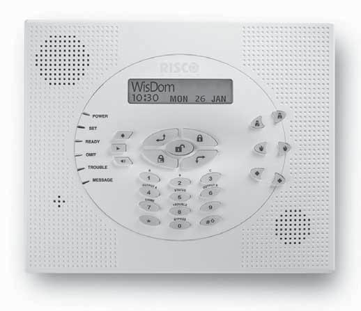
26 Using the WisDom s LEDs and Keys Figure 3-1: The WisDom Surface The WisDom surface contains six LED indicators, an LCD display and a variety of keys. The LEDs have a different indication during programming mode than in normal operation mode. The LED s indication in normal operation mode is described in the WisDom user manual. The following table describes the LEDs and keys typical uses during the programming mode: Item Key/LED Programming Mode 1 Power LED Slow flashing LED = an active programming session 2 Set LED 3 Ready LED 4 Omit LED 5 Fault LED 6 Message LED These LEDS are off (unlit) during programming operations. 7 These keys do not function during programming operations Use this key to exit the current programming selection and 8 move up to the next higher level in the programming hierarchy. 9 Use this key to enter selected information into the system or to accept the current selection and access the lower level of options in the programming hierarchy 3-2 WisDom Installation and Programming Manual
27 Item Key/LED Programming Mode 10 LCD Program Display The LCD program display consists of two lines. The top line displays information about the main selection mode, and the bottom line displays information and/or data about the specific option set. Such data may be changed through keypad entry. When programming, up to 16-characters can be entered into a line, as required. 11 These keys do not function during programming operations 12 0 through 9 Use the numbered keys, 0 through 9, to key in numbers and/or special characters when labeling zones, areas, and partitions. (For information about how to use the keypad for labeling zones, areas, and partitions, refer to Chapter 4, Using the Engineer Programming Menus.) 13 Press either one of these keys to move back and forth through the programming level functions. These keys also change the position of the flashing cursor. When editing a selection, the cursor moves to the left or right respectively. 14 Use this key to toggle forward through the programming choices within a selection. 15 Use this key to toggle backward through the programming choices within a selection. 16 This key does not function during programming operations Engineer Programming from the WisDom Keys This section explains how to use the WisDom keys to access the Engineer Programming menu as well as how to restore the manufacturer's defaults, as described in the following sections: Accessing the Engineer Programming Menu, below Restoring Manufacturer's Programming Defaults, page 3-5 Keypad Timeout, page 3-6 WisDom Installation and Programming Manual 3-3
28 Accessing the Engineer Programming Menu This section describes how to access the Engineer Programming menu after the WisDom has been defaulted, as well as how to access it from the regular operation mode. To access the Engineer Programming Menu: 1. When you power up the system for the first time, the display of the regular operation mode will be: WisDom: --: From the regular operation mode press. The display will be: The display prompts you for authorization code (Grand master, Master or the Manager code). Enter code [1][2][3][4] (default for Grand Master), followed by. 3. After pressing the keypad displays the first User Functions option, as follows: User functions: 1)Omit zone Press [9] to select the Engineer option or use the the first option, as follows: key. The keypad displays Engineer: 1)Full prog. 4. Press [1] Full prog. to enter the full programming menu. The display prompts you for the Engineer code, as follows: GM/MST/MGR code: _ 5. Enter the authorization code (Grand master, Master or the Manager code) followed by. The following message display appears. Engineer code: NOTES: 1. The authorization code is defined by default as Enable. For more information refer to Chapter 4, Quick key [1][2][41]. 2. After the Engineer exits the programming menu, the engineer can access the Engineer programming for one hour without the authorization code. 6. Enter the default Engineer Code: [0][1][3][3] The code appears as on the LCD display, as follows: Engineer code: 3-4 WisDom Installation and Programming Manual
29 7. Press The following message display appears: Installation: Please wait, Followed by the following message: 8. Press to erase Wireless transmitters. The following message display appears: Choose YES (Y) or NO (N) using the key, to erase Or Use the key to abort and access the first main Engineer Programming menu option is displayed bellow: Engineer Prog: 1)System The Power LED begins flashing slowly at this point, indicating that you have entered a programming session. The main Engineer Programming menu options are available, as follows: [1] System [6] Report codes [2] Zones [7] Key Fobs [3] Programmable Outputs [8] Keypads [4] Codes [9] More Devices [5] Digicom [0] Exit Programming Each of the main Engineer Programming menu options enables you to access and program all of the WisDom options. Each option is also discussed in detail in Chapter 4, Using the Engineer Programming Menus. Restoring Manufacturer's Programming Defaults You may find it useful to be able to remove all changes made to the WisDom s programming and restore the default settings provided by the manufacturer.! IMPORTANT: Before defaulting the WisDom you should enable the Default Enable/Disable parameter that controls the authority to restore to the manufacture s defaults. The Default option for this parameter, as defined by the manufacturer is Enable. The quick programming key for this parameter is [1][7] from the main Engineer-programming menu. If you need to program this parameter, remember to exit the Engineer-programming menu, after you set your choice, and save your selection. To restore the WisDom to the manufacturer's defaults: 1. Make sure that the Default Enable/Disable parameter is set to Enable (The default as supplied by the manufacturer is Enable) 2. Disconnect all power from the WisDom. 3. Open the WisDom unit and position the default jumper J9, located on the PCB of the front panel, on both pins. WisDom Installation and Programming Manual 3-5
30 4. Reconnect the power to the WisDom. All the LEDs flash once and a long beep is heard. The following message is displayed: WisDom: --: The Omit LED is ON as long as the default jumper (J9) is on both pins. 5. Reposition the J9 default jumper on one of the J9 pins (where it resides for safekeeping). 6. Access the Engineer-programming menu as described on page 3-4 and program the system, as required. Remember that the Engineer Code has been restored to the manufacturer's default [0][1][3][3]. 7. When you finish your programming, exit the Engineer-programming menu by selecting [0] Exit from the main Engineer-programming menu. The display prompts you to save your changes by displaying the following message: Do you want to save the data? Y 8. Confirm saving the data by pressing the key. A short beep is heard and the following messages are displayed. Please wait Data saving 9. When the function is completed, the display goes to regular operation mode, as follows: WisDom: --: If while exiting, the following display appears, this means that the J9 default jumper is NOT positioned on 1 pin, but wrongly positioned on both J9 pins. Keypad Timeout If, after 15 minutes, during the Engineer programming, no entry is made to the keys the WisDom will produce an audible reminder, consisting of several beeps in rapid succession, along with the following display: Timeout Hit any key Pressing any key stops the beeping. To re-enter the Engineer Programming menu, you must key in your Engineer code again and press. 3-6 WisDom Installation and Programming Manual
31 Using the Program Transfer Module (PTM) The Program Transfer module (PTM) is used to create and apply standard programming templates. In addition, you can use the PTM on powered-up, properly functioning WisDom, which have been previously programmed. To create a Programming Template by copying from a programmed WisDom: Use a programmed WisDom system to create a Programming Template to be applied to other WisDom systems. The programming on the WisDom is ready for copying. To install a Programming Template on a WisDom system: Use an existing Programming Template on a PTM to install programming on a WisDom system. To copy from a programmed WisDom system into the PTM: 1. Position the PTM on the J1 BUS connector located on the PCB of the back panel with the red LED not facing the row of terminals. The red LED flashes slowly. 2. Remove the J9 Default Jumper plug from its position on one pin and position it on both of the two pins. 3. Access the main Engineer Programming menu by pressing [9] [1] from the regular operation mode (see page 3-4). 4. Without making any changes, exit the main Engineer Programming menu by pressing [0]. The LED on the Program Transfer module flashes rapidly, and the keypad displays the following: When the LED stops flashing rapidly, the WisDom beeps twice and displays the following: Data is saved Please wait.. Then the display returns to the normal operation mode display. 5. Remove the PTM from the J1 BUS connector. 6. Position the J9 jumper on one of the pins. 7. The PTM now contains a copy of the Main Panel's configuration. To load the Program Transfer module s stored configuration into a WisDom: 1. Position the PTM on the J1 BUS connector located on the PCB of the back panel with the red LED not facing the row of terminals. The red LED flashes slowly. 2. Remove the J9 Default Jumper plug from its position on one pin and position it on both of the two pins. 3. Momentarily remove all power from the WisDom (both Mains and Battery). WisDom Installation and Programming Manual 3-7
32 4. Restore power to the WisDom. After a moment, the LED on the Program Transfer module flashes rapidly, indicating that the information is being copied from the PTM to the WisDom system. The LCD keypad displays the following: PLEASE WAIT... When the LED stops flashing rapidly, the WisDom beeps once, and its display returns to the normal operation mode display. 5. Remove the PTM from the J1 BUS connector. 6. Position the J9 jumper on one of the pins. 7. Reset its TIME and DATE, which were lost when power was removed. (Refer to the WisDom User's Manual.) 3-8 WisDom Installation and Programming Manual
33 Chapter 4: Using the Engineer Programming Menus This chapter describes the WisDom s Engineer programming options and functions, as well as all quick key shortcuts. They are presented in a table of menus are listed according to their number, as follows: 1 System, page Zones, page Programmable Outputs, page Codes, page Digicom, page Report Codes, page Key-Fobs, page Keypads, page More Devices, page Exit Programming, page 4-99 Engineer Programming Menu Conventions The following pages describe the options and functions that can be accessed via the WisDom keys and how to program them. Remember that these options are accessed from the Engineer Programming menu, described in Chapter 3, Programming the WisDom. Each procedure also provides information about programming the system using the relevant Quick Keys. The column headings appear as follows: Column Heading Quick Keys Parameter Default Range Description A shortcut to program an option. The shortcuts are listed in numerical sequence. The name of the option programmed by the selection. The factory default. The default values have been carefully chosen and are suitable for most installations.. Where applicable, the range of possible values. WisDom Installation and Programming Manual 4-1
34 To program the system using Quick Keys: 1. Access the Engineer Programming menu and select the main menu option that you want to access (refer also to Chapter 3, Programming the WisDom). 2. Press the Quick Keys listed in sequence (from left to right) to locate the option listed in the Parameter column and then press. When programming items in sequence, you can use the key to toggle the options. key to exit to the previous level and the 1 System The System menu provides access to submenus and their related parameters that are used for programming configuration settings applicable to the entire system. After you access the System menu from the main Engineer Programming menu, as described in this section, you can access the following sub-menus: 1 1 Timers, page Parameters, page Receiver, page Clock, page Labels, page Sound, page Default jumper, page Service Information, page Version, page 4-20 To access the System menu: From the Engineer Programming menu, press [1], or press the or keys until you find the number [1] System option and then press. The first submenu (Timers) appears: System prog.: 1)Timers You are now in the System menu and can access the required submenus, as described in the following sections. 1 1 System: Timers The Timers menu contains parameters that specify the duration of an action. To access the Timers menu: 1. Access the System menu, as described on page From the System menu, press [1] to access the Timers menu options. The following display appears: System timers: 1)Ex/En delay WisDom Installation and Programming Manual
35 3. Access and configure the parameters in the Time Define menu, as follows: System: Timers Quick Keys Parameter Default Range Exit/Entry Delay 1 Exit/Entry Delays (Group 1) Entry Delay 1 45 seconds 0-45 seconds Duration of Group 1 Entry Delay Exit Delay 1 45 seconds 0-45 seconds Duration of Group 1 Exit Delay Exit/Entry Delay 2 Exit/Entry Delays (Group 2) Entry Delay 2 45 seconds 0-45 seconds Duration of Group 2 Entry Delay Exit Delay 2 45 seconds 0-45 seconds Duration of Group 2 Exit Delay Bell Timeout 04 minutes minutes Duration of the external sounder(s) during alarm Bell Delay 00 minutes minutes The time delay before the keypad sounder and the external sounder operates after the onset of an alarm AC Off Delay Time 60 minutes 0-60 minutes In the case of a loss of AC power, this parameter specifies the delay period before reporting the event or operating the Programmable Output. If the delay time is set to 0 (zero), there will be no delay period Line Cut Delay 04 minutes minutes In the case of a cut phone line, this parameter specifies the delay period before reporting the event into the event log or operating the Programmable Output Indicates no phone line supervision Confirm Time Window 60 minutes minutes Specifies a time period that starts when an alarm is triggered for the first time. If a second alarm is triggered before the end of the confirmation time window, the WisDom will send a confirmed alarm to the Monitoring Station. Reopening the first zone for sequential alarm during the confirmation time window will reset the timer Start Confirmation 0 minutes minutes Specifies that the WisDom cannot start a sequential confirmation process until the timer has expired. This time starts when the system has set and will prevent confirmed alarms being generated in situations when a person has been accidentally locked in the building. WisDom Installation and Programming Manual 4-3
36 System: Timers Quick Keys Parameter Default Range Accessory supervision time minutes Specifies how often the wireless accessory generates a supervision signal (wireless sounder or wireless GSM). If the system bit Comm Fail (Quick key [1][2][33] is defined as YES, a communication fault will be regarded as a tamper alarm. If any of the accessories does not respond to the request, at least once, during the supervision time of the WisDom receiver (Quick Key [1][3][3] ) the WisDom will regard the accessory as Lost. IMPORTANT: The supervision time of the WisDom receiver (Quick key [1][3][3]) should be higher than the accessory supervision time ([1][1][9]) in order to eliminate false lost event. 1 2 System: Parameters The System Parameters menu contains parameters that control specific system operations. To access the Parameters menu: 1. Access the System menu, as described on page From the System menu, press [2] to access the Parameters menu options. The following display appears: Parameters: 1)Quick set N 3. Access and configure the parameters in the Parameters menu, as follows: System: Parameters Quick Keys Parameter Default Range Quick Set NO YES/NO YES: Eliminates the need for a User Code when Setting in PART SET or AWAY modes. NO: A valid User Code is required for Setting in PART SET or AWAY modes Quick PO YES YES/NO YES: A user can activate a Programmable Output without the need to enter a User Code. NO: A User Code is required to activate a Programmable Output Allow Omit YES YES/NO YES: Permits zone omitting by authorized system users after entering a valid User Code. NO: Zone omitting is NOT permitted Quick Omit NO YES/NO YES: Eliminates the need for a valid User Code when omitting zones. NO: Qualified users must enter a valid User Code to omit zones. 4-4 WisDom Installation and Programming Manual
37 System: Parameters Quick Keys Parameter Default Range False Code Fault YES YES/NO YES: A False Code report is sent to the ARC (Alarm Receiving Centre) after three successive attempts at Setting or Unsetting in which an incorrect User Code is entered. No alarm sounds at the premises, but a fault indication appears on the system's keypad(s). NO: A local alarm is sounded at the premises Bell Squawk YES YES/NO YES: If a keyswitch or a rolling code remote control is used (also when setting with a keypad), a brief "chirp" is produced from the system's external sounder(s) (at the conclusion of the Exit Delay period), as follows: One chirp indicates the system is set (also when arming with a keypad). Two chirps indicate the system is unset. Four chirps indicate the system is unset after an alarm. NO: No "chirp" is produced Bell 30/10 NO YES/NO YES: The sounders cease to sound for 10 seconds after each 30 seconds of operation. NO: The sounders operate without interruption Alarm Line Fault NO YES/NO YES: Activates the sounders if the phone line is cut or the telephone service is interrupted for the time defined in the Phone Line Cut Delay Time parameter. (Refer to Phone Line Cut Delay Time, page 4-3.) NO: No activation occurs Minute Omit NO YES/NO YES: Omits all zones automatically for 3 minutes when power is restored to an "unpowered" system to allow for the stabilization of motion and/or smoke detectors. NO: No omitting occurs Audible Panic YES YES/NO YES: The sounders operate when a "Police Alarm" is initiated at the keypad or when a Panic Zone is activated. NO: No sounder operation occurs during a keypad "Police Alarm," making the alarm truly "silent" (Silent Panic). The system also transmits a Panic report to the Alarm Receiving Centre Buzzer Bell NO YES/NO YES: If an alarm occurs when the system is set in the Part Set mode, a buzzer sounds for 15 seconds before the sounders operate. NO: An alarm in the Part Set mode causes sounders to operate simultaneously. WisDom Installation and Programming Manual 4-5
38 System: Parameters Quick Keys Parameter Default Range Fire Temporal Pattern NO YES/NO YES: During a fire alarm, the sounders produce a pattern of three short bursts, followed by a brief pause. NO: During a fire alarm, the flow of sounds produced by the sounder is a pattern of 2 seconds ON, then 2 seconds OFF Code Grand Master YES YES/NO YES: Only a user with the Grand Master Authority Level can change all user codes, along with the TIME and DATE. NO: Users with the Master and Manager Authority Levels can change their own User Codes, all codes with a lower Authority Level, and the TIME and DATE Audible Jamming NO YES/NO Relates to the Jamming Time parameter, described on page YES: Once the specified time is reached, the WisDom activates the sounder and sends a Report Code to the Central Station. (Refer to Jamming Fault, page 4-78.) NO: Once the specified time is reached the sounders do not operate Tamper Reset NO YES/NO YES: It is necessary to enter the Engineer Code to reset a Tamper Alarm. Therefore, resetting Tamper Alarm require the intervention of the alarm company. However, the system can still be set. NO: Correcting the problem resets a tamper Alarm, requiring no alarm company help Engineer Reset YES YES/NO YES: It is necessary to enter the Engineer Code to reset an alarmed partition after it's been unset. This requires the intervention of the alarm company. Before the READY LED can light, all zones within the partition must be secured. NO: Once an alarmed partition is reset, the READY LED lights when all zones are secured Abort Alarm NO YES/NO YES: If an alarm is sent in error, it is possible for the ARC Alarm Receiving Center) to receive an Abort Alarm Code, sent subsequent to the initial Alarm Code. This happens if a valid User Code is entered to reset the alarm within 90 seconds of initiation. NO: No Abort Alarm Code can be sent once an alarm has been triggered Summer/Winter Clock NO YES/NO YES: The WisDom automatically sets its Time of Day clock one hour ahead in the spring (on the last Sunday in March) and one hour back in the Autumn (on the last Sunday in October). NO: No automatic time accommodation is made. 4-6 WisDom Installation and Programming Manual
39 System: Parameters Quick Keys Parameter Default Range Forced Keyswitch Setting NO YES/NO YES: Keyswitch Setting is performed on any partition. Any violated (not READY) zone(s) in the partition will be omitted automatically. The partition is then "force set," and all intact zones are capable of producing an alarm. NO: The partition cannot be set using a keyswitch until all violated (not READY) zones are secured Pager NO YES/NO Relates to the use of an alphanumeric pocket pager with the option to notify the customer when an event occurs. The pager's phone number must be programmed as a Follow-Me device in the WisDom's User Functions. YES: When a call is made, event information is displayed on the alphanumeric pager. The following examples and tips clarify the YES option. Enter the phone number, as described in the WisDom User's Manual, by entering the letter [B] (which instructs the Digicom to wait a fixed period of time before continuing). Add the partition number to which the Follow-Me relates. The following messages are delivered automatically to the pager. Displayed Meaning 1# The system (or partition) is set. 2# The system (or partition) is unset. 3# The system (or partition) is in ALARM mode. In the example below, the first column displays the characters that are added after you enter the letter [B]: Characters Added After [B] If Displayed Meaning 1 11# Partition 1 is set. 2 22# Partition 2 is disarmed. 3 33# Partition 3 is in ALARM mode. NO: The WisDom calls a pager during an alarm situation only in the partition for which it is programmed as a Follow-Me device. There are no enhancements to the standard message. WisDom Installation and Programming Manual 4-7
Agility Engineer Manual. Important Notice This guide is delivered subject to the following conditions and restrictions:
 Engineer Manual ` Agility Engineer Manual Important Notice This guide is delivered subject to the following conditions and restrictions: This guide contains proprietary information belonging to RISCO Group.
EVO192 v3.0 Fire and Burglary What s New
 EVO192 v3.0 Fire and Burglary What s New Compatibility: EVO192 v3.0 TM50 v1.31 K641 v2.41 Overview: CP-01 Compliancy Wiring Diagram The following sections/options have been added to the EVO192 panel. They
Watchguard WGAP864 User Manual
 Watchguard WGAP864 User Manual v1.0 Issued September 2016 1 2 Table of Contents Glossary... 5 1. Introduction to your Watchguard WGAP864... 6 2. Before Operating your Alarm System... 6 3. Understanding
Important Notice This guide is delivered subject to the following conditions and restrictions:
 Installer Manual Important Notice This guide is delivered subject to the following conditions and restrictions: This guide contains proprietary information belonging to RISCO Group. Such information is
Contents. Glossary
 Contents Glossary ------------------------------------------------------------------------------------------------------ 6 1. Introduction to the IDS 1632 -------------------------------------------------------------
All-In-One Wireless Security System V3.2 Programming Guide. Model # MG6130 / MG6160
 All-In-One Wireless Security System V3.2 Programming Guide Model # MG6130 / MG6160 We hope this product performs to your complete satisfaction. Should you have any questions or comments, please visit www.paradox.com
IDS816 User Manual H Issued January 2009
 1 Contents Glossary-------------------------------------------------------------------------------------------------------------------6 1. Introduction to the IDS 816---------------------------------------------------------------------------7
RANGER 7600 DOWNLOADABLE CONTROL COMMUNICATOR INSTALLATION MANUAL
 RANGER 7600 DOWNLOADABLE CONTROL COMMUNICATOR INSTALLATION MANUAL TABLE OF CONTENTS 1. TABLE OF CONTENTS... P.1 2. GENERAL DESCRIPTION... P.2... 3. STANDARD AND OPTIONAL PARTS LIST... P.2... 4. FEATURE
User s Guide. SUB-MA7240O-0001.OG.Solution doc. Created: 6/05/03. Last Updated: 23/09/03. MA7240AO-0001 Version 1.0
 User s Guide SUB-MA7240O-0001.OG.Solution40-111.doc Created: 6/05/03 Last Updated: 23/09/03 MA7240AO-0001 Version 1.0 2 Table Of Contents User List...6 Quick Reference..7 Features...7 Keypad User's Guide...8
Digiplex System V2.14 / V2.2ACC. Control Panel Programming Guide
 Digiplex System V2.14 / V2.2ACC Control Panel Programming Guide Table of Contents Getting Started...2 What Do I Do First?...2 How Do I Program the Control Panel?...2 Single Digit Entry Method...2 Multiple
System Introduction. 1.1 Specifications S E C T I O N 1
 System Introduction S E C T I O N 1 1.1 Specifications Control Panel Specifications Flexible Zone Configuration: 8 Fully Programmable Zones 37 Access Codes: 32 User, 1 System Master, 2 Partition Master
System Introduction. 1.1 PC5015 Specifications S E C T I O N 1
 1.1 PC5015 Specifications System Introduction S E C T I O N 1 Flexible Zone Configuration: 8 Fully Programmable Zones 38 Access Codes: 32 User, 1 System Master, 2 Partition Master, 2 Duress and 1 maintenance
Fire Burglary Instruments Inc. XL-2G Gold Control/Communicator Installation Training Seminar Rev. 5/96
 Fire Burglary Instruments Inc. XL-2G Gold Control/Communicator Installation Training Seminar Rev. 5/96 XL-2G Gold Product Overview 7 Zones (6 programmable + panic or keyswitch zone) Fast Loop Response
DL150 DOWNLOADABLE CONTROL COMMUNICATOR INSTALLATION MANUAL
 DL150 DOWNLOADABLE CONTROL COMMUNICATOR INSTALLATION MANUAL TABLE OF CONTENTS 1. GENERAL DESCRIPTION... 2 2. STANDARD AND OPTIONAL PARTS LIST... 2 3. FEATURE DEFINITIONS... 3 4. TERMINAL DRAWING AND SPECIAL
NetworX NX-8V2. LED Keypad User Manual
 NetworX NX-8V2 LED Keypad User Manual POWER Light is on when AC power is present; flashes to indicate a low battery condition. ARMED Light is on when armed; off when disarmed; flashes to indicate a previous
All-In-One Wireless Security System V1.0. Model #: MG-6060
 All-In-One Wireless Security System V1.0 Model #: MG-6060 Reference and Installation Manual DRAFT Table of Contents Introduction... 5 About Magellan and this Manual... 5 Conventions... 5 Specifications...
Testing the System. Battery Test. Dialer Test. Fire Drill Test (Code + [#] + 69) One-Man Fire Walk-Test (Code + [#] + 68)
![Testing the System. Battery Test. Dialer Test. Fire Drill Test (Code + [#] + 69) One-Man Fire Walk-Test (Code + [#] + 68)](/thumbs/79/79864325.jpg "Testing the System. Battery Test. Dialer Test. Fire Drill Test (Code + [#] + 69) One-Man Fire Walk-Test (Code + [#] + 68)") F A 1 7 0 0 c Testing the System Battery Test When AC power is present, the FA1700C runs a brief battery test every 60 seconds to determine if there is a battery connected, and runs an extended battery
F A 1 7 0 0 c Testing the System Battery Test When AC power is present, the FA1700C runs a brief battery test every 60 seconds to determine if there is a battery connected, and runs an extended battery
Installation and Programming Manual
 Installer Manu Installation and Programming Manual Important Notice This guide is delivered subject to the following conditions and restrictions: This guide contains proprietary information belonging to
TABLE OF CONTENTS TABLE OF CONTENTS 1
 TABLE OF CONTENTS TABLE OF CONTENTS 1 FEATURES 2 Keypad Programmable... 2 EEPROM Memory... 2 Static/Lightning Protection... 2 Supervision... 2 Operation... 2 SPECIFICATIONS 2 PC1550 Control Panel... 2
Summary of Keypad Main User Commands
 User Manual Summary of Keypad Main User Commands Full Set Code > Part Set Code > System Unset Silence an Alarm Partition Full Set Partition Part Set Code> Code> Code > > Partition No. > Code > > Partition
HA-263K HA-263D. OWNER'S MANUAL Installation And Operation 8-ZONE ALARM CONTROL PANEL FOR HOME AND OFFICE PROTECTIONS OPEN THE CABINET FOR SERVICE
 D (OPERATION) INITIATE A DYNAMIC BATTERY TEST The system tests the back-up battery once every 24 hours. The owner can initiate a dynamic battery test at any time with the following codes while the system
Important Notice This guide is delivered subject to the following conditions and restrictions:
 Engineer Manual Important Notice This guide is delivered subject to the following conditions and restrictions: This guide contains proprietary information belonging to RISCO Group. Such information is
System Introduction. 1.1 Specifications
 System Introduction S E C T I O N 1 1.1 Specifications Downloading Software Support PC585 uses DLS-1 v6.5 and up. Flexible Zone Configuration Four fully programmable zones; system expandable to eight zones
IDS S E C U R I T Y IDS816. User Manual MANUAL NO C ISSUED APRIL 2005 VERSION 2.00
 INHEP DIGITAL IDS S E C U R I T Y IDS816 User Manual MANUAL NO. 700-283-01C ISSUED APRIL 2005 VERSION 2.00 Contents 1. Introduction to the IDS816... 4 2. Understanding the Keypad Indicators... 4 3. Programmable
IDS S E C U R I T Y IDS816. User Manual. MANUAL NO A ISSUED November 2004 VERSION 1.00
 INHEP DIGITAL IDS S E C U R I T Y IDS816 User Manual MANUAL NO. 700-283-02A ISSUED November 2004 VERSION 1.00 Contents 1. Introduction to the IDS816... 4 2. Understanding the Keypad Indicators... 4 3.
A1UL PERS. Personal Emergency Response System. For Technical Support Please Contact Your Service Provider Or Distributor
 A1UL PERS Personal Emergency Response System TABLE OF CONTENTS 1. READ THIS FIRST... 1 2. SYSTEM OVERVIEW.. 1 3. COMPONENTS 2 4. UNIT OPERATION! Standby Mode.. 3! Emergency Activation. 3! Answering Incoming
USER GUIDE HARDWIRED CONTROL PANELS
 USER GUIDE HARDWIRED CONTROL PANELS Scantronic Contents 1. Introduction... 3 The Alarm System... 3 The Keypads... 3 The 725r Remote Setting Device... 6 About This Guide... 6 2. Everyday Operation... 7
All-In-One Wireless Security System V1.0. Model #: MG Reference and Installation Manual
 All-In-One Wireless Security System V1.0 Model #: MG-6060 Reference and Installation Manual Table of Contents Introduction... 3 About Magellan and this Manual... 3 Conventions... 3 Specifications... 3
GLOBAL. InstallatIon & operation manual
 InstallatIon & operation manual INDEX 1. INTRODUCTION... 5 2. FEATURES AND FUNCTIONS 2.1 Reporting Options... 2.2 Interfaces... 2.3 Programming... 2.4 Indicators and Controls...... 6 6 6 6 6 3. INSTALLATION...
RANGER 8980E DOWNLOADABLE CONTROL COMMUNICATOR INSTALLATION MANUAL
 RANGER 8980E DOWNLOADABLE CONTROL COMMUNICATOR INSTALLATION MANUAL TABLE OF CONTENTS GENERAL DESCRIPTION...2 STANDARD AND OPTIONAL PARTS LIST...2 FEATURE DEFINITIONS...3 TERMINAL DRAWING AND SPECIAL NOTES...4
System Introduction. Digital Communicator Specifications: Supports all Major Formats including SIA and Contact ID Event Initiated Personal Paging
 1.1 Specifications System Introduction S E C T I O N 1 Control Panel Specifications Flexible Zone Configuration: 8 Fully Programmable Zones 38 Access Codes: 32 User, 1 System Master, 2 Partition Master,
NetworX Series. NX-8 Commercial Fire Panel Installation and Startup
 NetworX Series NX-8 Commercial Fire Panel Installation and Startup 2004 GE Security All rights reserved. Printed in the United States of America. These instructions do not purport to cover all details
EC-P Zone Intruder Alarm System
 EC-P10 10-20 Zone Intruder Alarm System Installation Manual Contents 1. System Overview... 4 System Configuration... 4 Control Panel... 5 Remote Keypads... 5 EC-LED Remote Keypad... 5 EC-LCD Remote Keypad...
Security System. User Guide for the LED Command Center
 Security System User Guide for the LED Command Center National Security Systems Inc (800)457-1999 MY SECURITY COMPANY IS: CALL BEFORE TEST: THIS SECURITY SYSTEM IS CONNECTED TO TELEPHONE NUMBER: THE SECURITY
RANGER 8600 DOWNLOADABLE CONTROL COMMUNICATOR INSTALLATION MANUAL
 RANGER 8600 DOWNLOADABLE CONTROL COMMUNICATOR INSTALLATION MANUAL TABLE OF CONTENTS GENERAL DESCRIPTION... 2 STANDARD AND OPTIONAL PARTS LIST... 2 PARTS DIAGRAM... 3 TERMINAL DRAWING AND SPECIAL NOTES...
Installation Manual Premier 412/816/832. Issue 10
 Installation Manual Premier // Issue 0 Premier // Installation Manual 5. Operating the System Introduction Before attempting to operate the alarm system ensure you have familiarised yourself with all the
Control/Communicator Installation Manual
 DAS NETWORX NX-12 Control/Communicator Installation Manual General Description...2 Ordering Information...2 Option Definitions...3 Programming the LED Code Pads...5 Programming the NX-12...9 Types of Programming
Independent Zone Control (I.Z.C.)
") Operation and Installation Guide Independent Zone Control (I.Z.C.) DELAYED INSTANT ARMED 1 2 3 4 7 5 6 8 9 * * fi Radionics R D279A Operation & Installation Guide 46456B Page 2 Copyright 2000 Radionics
Operation and Installation Guide Independent Zone Control (I.Z.C.) DELAYED INSTANT ARMED 1 2 3 4 7 5 6 8 9 * * fi Radionics R D279A Operation & Installation Guide 46456B Page 2 Copyright 2000 Radionics
HEXA PROGRAMMING: STREAMLINED SECTION PROGRAMMING
 -961212-0004 SOFTWARE VERSION 3.10 CONTROL PANEL RESET: Installer lock must be unlocked. ( 058: enter any value other than 147) Power down reset (1) Remove battery and AC to power down the unit. (2) Connect
PROGRAMMING GUIDE SPECTRA CONTROL PANELS V , 1725EX, 1728 AND 1728EX 1755, 1755EX, 1758, AND 1758EX
 PROGRAMMING GUIDE SPECTRA CONTROL PANELS V1.2 1725, 1725EX, 1728 AND 1728EX 1755, 1755EX, 1758, AND 1758EX TABLE OF CONTENTS HOW DO I PROGRAM THE SYSTEM?... 4 Single Digit Data Entry Method (Hexadecimal
External Wireless Sounder
 External Wireless Sounder Model: WL RWS401 Installation and Programming Instructions Table of Contents Introduction... 3 Operational Functions... 3 Alarm / Tamper Indication... 3 Low Battery Indication...
NETWORX TM. User manual NX-4
 NETWORX TM User manual NX-4 POWER Light is on when AC power is present; flashes to indicate a low battery condition. ARMED Light is on when armed; off when disarmed; flashes to indicate a previous alarm.
Installation Instructions
 NX-148E-RF LCD Touchpad with Receiver 466-2198C February 2006 Copyright 2006, GE Security Inc. Contents Product summary 1 Installation 1 Transmitter programming 2 Touchpad programming 5 Reference tables
Version 1.03 January-2002 USER S MANUAL
 Version 1.03 January-2002 1 USER S MANUAL 2 Version 1.03 January-2002 System Details CUSTOMER:...... PHONE:... FAX:... INSTALLED BY:...... PHONE:... FAX:... MAINTENANCE & SERVICE:...... PHONE:... FAX:...
AXI LED USER MANUAL (REV. 1.0)
") Security & Home Automation System AXI LED USER MANUAL (REV. 1.0) CONTENTS PREFACE FEATURES LED KEYPAD OUTLOOK 1.0 LIGHT INDICATION 1 2 4 6 CHAPTER 1: ALARM SYSTEM CONTROL 1.0 USING LED KEYPAD 1.0.1 ARMING
Security & Home Automation System AXI LED USER MANUAL (REV. 1.0) CONTENTS PREFACE FEATURES LED KEYPAD OUTLOOK 1.0 LIGHT INDICATION 1 2 4 6 CHAPTER 1: ALARM SYSTEM CONTROL 1.0 USING LED KEYPAD 1.0.1 ARMING
JA-63 PROFI Alarm System MGK55402
 Contents: 1 Architecture of the control panel... 4 2 Control panel installation... 4 2.1 Mains supply connection... 5 3 Antenna for the radio module... 5 3.1 Rubber rod antenna used in the control panel...
TABLE OF CONTENTS. General Description Standard and Optional Parts List Feature Definitions Comments about the 8600E...
 5$1*(5( DOWNLOADABLE CONTROL COMMUNICATOR INSTALLATION MANUAL TABLE OF CONTENTS General Description... 2 Standard and Optional Parts List... 2 Feature Definitions... 3 Comments about the 8600E... 4 Terminal
SOFTWARE VERSION 2.20 CONTROL PANEL RESET: Installer lock must be unlocked. (Address 255: enter any value other than 147)
") -961112-0003 SOFTWARE VERSI 2.20 CTROL PANEL RESET: Installer lock must be unlocked. ( 255: enter any value other than 147) Power down reset (1) Remove battery and AC to power down the unit. (4) Wait 3
-961112-0003 SOFTWARE VERSI 2.20 CTROL PANEL RESET: Installer lock must be unlocked. ( 255: enter any value other than 147) Power down reset (1) Remove battery and AC to power down the unit. (4) Wait 3
Power Wave Zone Alarm Panel V8.5. Installation Manual
 Power Wave - 8 8 Zone Alarm Panel V8.5 Installation Manual 7 December 2001 Crow (Aust) Electronic Engineering Pty Ltd Corporate Head Office: 429 Nepean Hwy, Brighton East, Vic., 3187 Australia Phone: +61
Installation & Programming Guide
 Alert Version 8 Zone Control Arrowhead Alarm Products Ltd Installation & Programming Guide Proudly Designed and Manufactured in New Zealand Arrowhead Alarm Products Ltd PHONE: (09) 579 7506 FAX: (09) 579
X64 Wireless Training
 X64 Wireless Training IDS Contents 1 Contents Features 3 Wireless Hardware 4 IDS & Duevi integration PCB 5 LED operation 5 Wireless Device Hardware setup 6 Location 260 7 LED Keypad Instructions 7 Adding
&RPPHUFLDO%XUJODU\ 3DUWLWLRQHG6HFXULW\6\VWHP ZLWK6FKHGXOLQJ
 READY ARMED READY 1 OFF 7 INSTANT READY 2 AWAY 8 CODE 6BYPASS 9 CHIME 9,67$% &RPPHUFLDO%XUJODU\ 3DUWLWLRQHG6HFXULW\6\VWHP ZLWK6FKHGXOLQJ 8VHU*XLGH ARMED READY 1 OFF 2 AWAY 3 STAY 4 MAX 5 TEST 6 BYPASS
TABLE OF CONTENTS. FOR THE RECORD 15 PROGRAMMING WORK SHEETS 16 CONTROL PANEL WIRING DIAGRAM inside back cover
 TABLE OF CONTENTS FEATURES 2 SPECIFICATIONS 2 INSTALLATION 3 Mounting the Panel... 3 Mounting the Keypad... 3 Auxiliary Power Connection... 3 PGM Terminal Connections... 3 Bell/Siren Connection... 3 Keypad
SOFTWARE VERSION 2.20 CONTROL PANEL RESET:
 -961112-0002 SOFTWARE VERSI 2.20 CTROL PANEL RESET: Installer lock must be unlocked. ( 255: enter any value other than 147) Power down reset (1) Remove battery and AC to power down the unit. (4) Wait 3
Alarm Control Panel WIC-16Z4P WIC-5Z2P. Installation & Operation User Manual
 WIC-16Z4P WIC-5Z2P Installation & Operation User Manual Page : 1/34 INDEX # Function Page 1 Abort Current Communication and Clear Reporting Queue (*59) 13 2 Abort Current Communications (*59) 10 3 Account
MG5000 V2.4 MG5050 V2.4 SP5500 V2.4 SP6000 V2.4 SP7000 V2.4. Programming Guide
 MG5000 V2.4 MG5050 V2.4 SP5500 V2.4 SP6000 V2.4 SP7000 V2.4 Programming Guide We hope this product performs to your complete satisfaction. Should you have any questions or comments, please visit www.paradox.com
P Zone Expandable Hybrid Security System
 Page 1 of 11 up to 8 hardwired keypads and 4 wireless keypads 4 hardwired keypads available with zone input PWLS910 wireless handheld keypad added wireless control is provided by - PWLS908 wireless panic
Centaur TM II Cube Slave Alarm Signalling Equipment INSTALLATION GUIDE
 Centaur TM II Cube Slave Alarm Signalling Equipment INSTALLATION GUIDE General Description This guide provides a summary for installing and configuring the Centaur TM Cube Slave Alarm Signalling Equipment
VISTA-32FBPT. Commercial Fire and Burglary Partitioned Security Systems with Scheduling. User Guide /12 Rev. B
 VISTA-32FBPT Commercial Fire and Burglary Partitioned Security Systems with Scheduling User Guide 800-11045 2/12 Rev. B 2 TABLE OF CONTENTS SYSTEM OVERVIEW...5 General...5 A Partitioned System...5 Zones...6
3 User s settings. 3.3 Internal clock setting
 2.9 Subsystem arming In a large building a sub control panel can be enrolled to the JA-63. The subsystem reports all alarms and failures to the main system. The installer can program if the systems will
**** **** A B ARMED FIRE FIRE C D READY OFF AWAY STAY 2 3 MAXIMUM TEST BYPASS PULL INSTANT CODE CHIME. First Alert READY. * 0 # Professional
 ARMED READY READY )$&&$&% )LUHDQG%XUJODU\ 3DUWLWLRQHG6HFXULW\6\VWHPV ZLWK6FKHGXOLQJ **** **** A B C D FIRE FIRE First Alert OFF AWAY STAY 2 3 1 4 5 6 7 8 9 MAXIMUM TEST BYPASS INSTANT CODE CHIME * 0 #
IDS S E C U R I T Y IDS816. User Manual MANUAL NO B ISSUED DEC 2004 VERSION 2.00
 INHEP DIGITAL IDS S E C U R I T Y IDS816 User Manual MANUAL NO. 700-283-01 B ISSUED DEC 2004 VERSION 2.00 Contents 1. Introduction to the IDS816... 4 2. Understanding the Keypad Indicators... 4 3. Programmable
M2M Services Ltd. RControl Alarm - Installer Manual V 1.0
 M2M Services Ltd. RControl Alarm - Installer Manual V 1.0 Content Content... 2 Wiring the power supply module... 3 Wiring a siren... 3 SMARTEnroll self-learning zones... 3 Wireless keyfobs... 3 Supported
8 plus and16 plus. User s Guide * # ent. esc GALAXY 16+ V2.XX TUE 30 JUN. IU ZST 962 Issue 2. A u B u
 8 plus and16 plus User s Guide GALAXY 16+ V2.XX 06.22 TUE 30 JUN 1 2 3 4 5 6 7 8 9 0 * # A u B u ent esc IU1-0018 ZST 962 Issue 2 Contents INTRODUCTION... 1 Glossary of Terms... 3 KEYPAD INFORMATION...
HEXA PROGRAMMING: STREAMLINED SECTION PROGRAMMING
 48ESEP-01 SOFTWARE VERSION 3.10 CONTROL PANEL RESET: Installer lock must be unlocked. (Address 058: enter any value other than 147) Power down reset (1) Remove battery and AC to power down the unit. (2)
&RPPHUFLDO)LUHDQG%XUJODU\ 3DUWLWLRQHG6HFXULW\6\VWHP ZLWK6FKHGXOLQJ
LUHDQG%XUJODU\ 3DUWLWLRQHG6HFXULW\6\VWHP ZLWK6FKHGXOLQJ") 9,67$)% &RPPHUFLDO)LUHDQG%XUJODU\ 3DUWLWLRQHG6HFXULW\6\VWHP ZLWK6FKHGXOLQJ 8VHU*XLGH FIRE FIRE * PULL K3522 3/99 TABLE OF CONTENTS SYSTEM OVERVIEW...4 General...4 A Partitioned System...4 Zones...5 Fire
9,67$)% &RPPHUFLDO)LUHDQG%XUJODU\ 3DUWLWLRQHG6HFXULW\6\VWHP ZLWK6FKHGXOLQJ 8VHU*XLGH FIRE FIRE * PULL K3522 3/99 TABLE OF CONTENTS SYSTEM OVERVIEW...4 General...4 A Partitioned System...4 Zones...5 Fire
The most user friendly Security Alarm System L S Section 1 Overview of System Section 2 Planning your Installation
 The most user friendly Contents Section 1 Overview of System 1.1 Kit Contents 1.2 Tools Required 1.3 System Features Security Alarm System L S 4 0 0 Section 2 Planning your Installation 2.1 Location of
USER'S GUIDE FA1220CV. 2-Partition Security System N7003-1V2 7/98
 USER'S GUIDE FA1220CV 2-Partition Security System N7003-1V2 7/98 SYSTEM OVERVIEW... 3 General... 3 A Partitioned System... 3 Zones... 3 Burglary Protection... 4 Fire Protection... 4 Alarms... 5 Emergency
Power Wave. 8 Zone Control Communicator. Crow Electronic Engineering P/L. Ver:8.54. Installation & Programming Guide.
 Power Wave 8 8 Zone Control Communicator Crow Electronic Engineering P/L Ver:8.54 Installation & Programming Guide 8 November 2000 Crow ( Aust ) Electronic Engineering Pty Ltd Corporate Head Office: 429
WIRELESS ALARM SYSTEM WITH TELEPHONE AUTO DIALER
 BAT.LOW AC WIRELESS ALARM SYSTEM WITH TELEPHONE AUTO DIALER THE SYSTEM THAT CALLS YOU! Our WIRELESS ALARM SYSTEM WITH TELEPHONE AUTO DIALER is designed to allow you to create your own security system.
DL-250 DOWNLOADABLE CONTROL COMMUNICATOR INSTALLATION MANUAL
 DL-250 DOWNLOADABLE CONTROL COMMUNICATOR INSTALLATION MANUAL TABLE OF CONTENTS 1. GENERAL DESCRIPTION...P.2 2. STANDARD AND OPTIONAL PARTS LIST...P.2 3. FEATURE DEFINITIONS...P.3 4. TERMINAL DRAWING AND
BENTEL SECURITY srl reserves the right to modify the technical specifications of this product without prior notice.
 BENTEL SECURITY srl reserves the right to modify the technical specifications of this product without prior notice. via Florida - Z.I. Valtesino - 63013 GROTTAMMARE (AP) - ITALY USER MANUAL: Digital communicator
PERMACONN PM1030 Includes DI300. Installation Manual
 PERMACONN PM1030 Includes DI300 Installation Manual Radio Data Comms Unit 5/20-30 Stubbs Street Silverwater NSW 2128 Telephone: 02 9352 1777 Facsimile: 02 9352 1700 Introduction The PERMACONN system provides
Digiplex Control Panel (DGP-848) - V4.0
 - V4.0") Digiplex Control Panel (DGP-848) - V4.0 DGP-848 Reference and Installation Manual TABLE OF CONTENTS INTRODUCTION... 4 1.0 1.1 Features... 4 1.2 Specifications... 4 INSTALLATION... 5 2.0 2.1 Location &
Digiplex Control Panel (DGP-848) - V4.0 DGP-848 Reference and Installation Manual TABLE OF CONTENTS INTRODUCTION... 4 1.0 1.1 Features... 4 1.2 Specifications... 4 INSTALLATION... 5 2.0 2.1 Location &
User's Manual VISTA-40 N7003V1 6/97
 S e c u r i t y S y s t e m User's Manual VISTA-40 N7003V1 6/97 SYSTEM OVERVIEW...3 General...3 A Partitioned System...3 Zones...3 Burglary Protection...4 Fire Protection...4 Alarms...5 Emergency (Panic)
Honeywell Control Panels FOR RESIDENTIAL AND COMMERCIAL INSTALLATIONS. Feature Charts
 Honeywell Control Panels FOR RESIDENTIAL AND COMMERCIAL INSTALLATIONS Feature Charts Control Panels FEATURE CHART LYNX Plus (L3000) (Supported Feature) (Not Supported) N/A (Not Applicable) LYNX Touch (L5210)
Security System With Scheduling. User Guide. N5943-8V4 7/04 Rev A
 ADEMCO VISTA-120 Security System With Scheduling User Guide N5943-8V4 7/04 Rev A Your Honeywell security system is designed for use with devices manufactured or approved by Honeywell for use with your
WLS900 Wireless Security System. Table of Contents. Your installing company is, Name: Address: Phone: Your monitoring station is, Name: Phone:
 Table of Contents WLS900 Wireless Security System 1 Introduction 2 2 Using the Keypad 3 3 Arming the System 4 3A - Arming Levels; 4 3B - Arming the System in the Away Mode 4 3C - Improper Arming Warning
HILLS Series LCD Code Pad User Manual
 HILLS Series LCD Code Pad User Manual THIS MANUAL IS FURNISHED TO HELP YOU UNDERSTAND YOUR SECURITY SYSTEM AND BECOME PROFICIENT IN ITS OPERATION. ALL USERS OF YOUR SECURITY SYSTEM SHOULD READ AND FOLLOW
DS9400 Series. Release Notes for Firmware V2.07. Fire Alarm Control Panel
 DS9400 Series EN Release Notes for Firmware V2.07 Fire Alarm Control Panel DS9400 Series Release Notes for Firmware V2.07 Trademarks Trademarks Gentex is a trademark of Gentex Corporation, Fire Protection
INSTALLATION GUIDE XTLN-WIFI PANEL
 INSTALLATION GUIDE XTLN-WIFI PANEL MODEL XTLN-WiFi INSTALLATION GUIDE FCC NOTICE This equipment has been tested and found to comply with the limits for a Class B digital device, pursuant to part 15 of
NetworX Series NX-1500E LED Keypad
 NetworX Series NX-1500E LED Keypad User Manual SECURITY SYSTEM NOTES Installing/Service Company For Service Call Central Station Duress Code FUNCTION CODES Function Code Controls Function This system
Destiny Destiny Owners Manual
 Destiny 4100 Destiny 4100 Owners Manual TABLE OF CONTENTS INTRODUCTION Control Panel...3 Detection Devices...3 Telephone Keypads...3 GLOSSARY... 4-5 LOCAL PHONE ACCESS Using Your Telephones As Keypads...6
MG Partition 64-Zone Wireless Console with GPRS/GSM Version 1.6. Section Programming Guide
 MG6250 2-Partition 64-Zone Wireless Console with GPRS/GSM Version.6 Section Programming Guide Things You Need to Know About this Programming Guide The MG6250 All-in-one Wireless Console can be programmed
External Wireless Sounder
 External Wireless Sounder WL S50 Installation and Programming Instructions 2 Wireless Sounder Instructions Table of Contents Introduction... 4 Operational Functions... 4 Alarm / Tamper Indication...4 Low
System Manual W A R N I N G. PC6O1O Software Version 2.1
 System Manual W A R N I N G This manual contains information on limitations regarding product use and function and information on the limitations as to liability of the manufacturer. The entire manual
System. For a better understanding of this product, please read this user manual thoroughly before using it.
 GSM Alarm System User s Manual For a better understanding of this product, please read this user manual thoroughly before using it. Chapter 1. Features Chapter 2. Control Panel Introduction Chapter 3.
LYNXR-2 Series Security System
 For Service Call: (866) 401-4842 LYNXR-2 Series Security System User Guide ARMED READY OFF 1 2 3 ESCAPE RECORD VOLUME AWAY 4 5 6 PLAY ADD STAY LIGHTS ON TEST BYPASS 7 8 9 DELETE LIGHTS OFF CODE CHIME AUX
JA-63 Profi User manual
 JA-63 Profi User manual Contents: 1 Limited warranty... 2 2 Indicators... 3 3 Controlling the system... 4 3.1 Arming... 5 3.2 Disarming... 6 3.3 Panic Alarm... 6 3.4 To stop ALARM... 6 3.5 Home arming...
(31/03/05) Version p1. INNER RANGE IQ. Programmer s Manual. Programmer s Manual Inner Range Pty. Ltd. Part Number:
 Version p1. INNER RANGE IQ. Programmer s Manual. Programmer s Manual Inner Range Pty. Ltd. Part Number:") (31/03/05) Version 2.604 p1 Programmer s Manual 2005. Inner Range Pty. Ltd. Part Number: 630047 p2 Version 2.604 (31/03/05) TABLE OF CONTENTS. Programming Methods... 3 1. Introduction 1.1 System Overview...
(31/03/05) Version 2.604 p1 Programmer s Manual 2005. Inner Range Pty. Ltd. Part Number: 630047 p2 Version 2.604 (31/03/05) TABLE OF CONTENTS. Programming Methods... 3 1. Introduction 1.1 System Overview...
VISTA-50P VISTA-50PUL
 Security System User's Manual VISTA-50P VISTA-50PUL N5943-6V1 Rev B 4/99 TABLE OF CONTENTS SYSTEM OVERVIEW...4 General...4 A Partitioned System...4 Zones...4 Fire Protection...5 Burglary Protection...5
ABORT Light flashes during an abort delay time; is on during or after an alarm report to the central station. EMERGENCY ACTIVATION KEYS
 POWER Light is on when AC power is present; flashes to indicate a low battery condition. CHIME Light is on when the chime feature is active. ABORT Light flashes during an abort delay time; is on during
GSM Alarm System. User s Manual. Profile. MOBILE CALL GSM Alarm System
 MOBILE CALL GSM Alarm System GSM Alarm System System disarmed 11/26/2013 User s Manual Profile For a better understanding of this product, please read this user manual thoroughly before using it. CONTENTS
PERS-3600 PERSONAL EMERGENCY REPORTING SYSTEM INSTALLATION & OPERATION INSTRUCTIONS
 PERS-600 PERSONAL EMERGENCY REPORTING SYSTEM BY BY INSTALLATION & OPERATION INSTRUCTIONS (760) 8-7000 USA & Canada (800) -587 & (800) 9-0 Toll Free FAX (800) 68-0 www.linearcorp.com CONTENTS CONTROL AREA
Control Panels. Control Panels for Commercial Applications. Control panels provide the central processing
 Control Panels Control Panels for Commercial Applications Control panels provide the central processing and logic for an integrated system. In a typical system, there are four major functions: inputs,
HEXA PROGRAMMING: STREAMLINED SECTION PROGRAMMING
 -961212-0004 SOFTWARE VERSI 3.10 CTROL PANEL RESET: Installer lock must be unlocked. (Address 058: enter any value other than 147) Power down reset (1) Remove battery and AC to power down the unit. (2)
M800, M800iD Plus, M1000 and M3000. User's Guide
 M800, M800iD Plus, M1000 and M3000 User's Guide Cooper Security Limited 2005 Every effort has been made to ensure that the contents of this book are correct. However, neither the authors nor Cooper Security
ATS1235 Advanced Wireless DGP on 868 MHz AM Installation Sheet
 ATS1235 Advanced Wireless DGP on 868 MHz AM Installation Sheet EN 1 2 1 3 2 4 1 5 12V 6 2 0V D+ D- CON3 7 CON1 ON 3 1 2 3 4 1234 8 3 4 1 0 ON 1 2 3 4 METAL METAL Address 1 1 0 ON 1 2 3 4 Address 2 2011
Table of Contents. Appendix A Special Characters 31
 Table of Contents Introduction 2 Section 1: General System Operation 3 1.1 Getting to Know Your System... 3 1.2 How to Arm... 4 1.3 Alternate Arming Methods... 5 1.4 Disarming... 6 1.5 Alarm Memory...
CC488. Quick Reference Guide Solution Ultima 880
 CC488 EN Quick Reference Guide Solution Ultima 880 CC488 Quick Reference Guide Notices EN 2 Copyright Notice Unless otherwise indicated, this publication is the copyright of Bosch Security Systems Pty