RBC20-60 Blast Chiller
|
|
|
- Silvester Laurence Whitehead
- 5 years ago
- Views:
Transcription

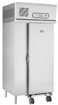
1 RBC20-60 Blast Chiller
2 Contents Page Introduction 1 to 2 Model Details 2 Controller Technical Detail 2 Parts List 2 Operating Instructions 3 to 6 Electrical Connections 7 Service Information 7 to 19 Diagnostics 8 Function Test 8 Passcode 8 Profiles 9 Parameter Access 9 Parameters 9 to 11 Parameter Definitions 11 to 18 Alarms and Warnings 18 Foot Print Test Operation 19 Probes 19 Technical Data 20 to 22 Wiring Diagrams 23 to Introduction. Cook Chill Operation. Blast chilling is a process to reduce the temperature of cooked food by swiftly arresting the cooking process, locking in its colour, flavour, texture and nutritional value. Department of health guidelines state that to safely blast chill food the temperature must be reduced from +70 c to +3 c within 90 minutes. Pre Chill Pre chilling ensures the correct cabinet temperature in the unit before chilling commences therefore improving the chilling performance. Soft Chilling. Soft chilling is the process of rapid but gentle chilling of food. This cycle brings down the food temperature to +3 c in no more than 90 minutes without the air or food temperature going below 0 c. This prevents large ice crystals forming therefore maintaining the texture, consistency and appearance of food such as vegetables, rice, pasta, custard and fruit with no dehydration or cell damage. Hard Chilling. Hard chilling is the process of general purpose chilling. This cycle brings down the food temperature to +3 c in no more than 90 minutes and is ideal for chilling meat pies, lasagne, pasta and individually portioned meals. The air temperature for this process goes down to -15 c for the first 70% of the cycle, to extract the maximum amount of heat from the product quickly. The air temperature then increases to +3 c for the final 30% of the time to reduce surface damage and ensure quality. Hard Chill Max. Hard chill max brings down the food temperature to +3 c in no more than 90 minutes and is used for chilling high density or high fat content food such as meat joints, stews or packaged products. The air temperature during the cycle is allowed to go down to -20 c. After either a pre-designated time has elapsed or product temperature has been achieved, the air temperature is allowed to rise to the hold value with the temperature being maintained at this level indefinitely. Surface Protection. Removing the heat energy from food product as rapidly as possible by the combination of powerful refrigeration and evaporator fans moving large volumes of cooled air can cause damage to the food product. The food product could have a form of Frost Burn caused by the fast moving air feeling cooler than the actual air temperature Wind Chill Effect. This may lead to product discoloration, dehydration, localised freezing and spoilage of the food product. Surface protection overcomes this by reducing the evaporation operation, and hence the air speed at pre-determined stages in the cycle to ensure that this does not happen. This is a discreet function and happens automatically without any intervention from the operator. To enable the surface protection; and determine at what stage it would be activated values are set in the service operating parameters. Longer Term Storage Hold Mode (Conservation) Upon the completion of the blast chilling cycle the controller will automatically enter the Hold mode. This will either be because the selection set time has elapsed or the product core temperature has been achieved. When the hold period commences an alarm will sound for a period denoted in the service operating parameters. 1
3 The controller will determine the temperature to be maintained during the hold phase based on the chilling cycle that has been completed. If a soft or hard chill has taken place the controller will maintain an air temperature of 2 c. The hold mode is principally intended as a temporary storage facility offering the operator flexibility until the product can be unloaded into a longer term storage units at the correct storage temperature. On occasion this hold period may become extended to operate overnight or to provide emergency refrigeration backup. In such instances defrosting would automatically occur as necessary. Model Details. The RBC is capable of blast chilling 60kg of product from +70 c to +3 c in 90 minutes with entry temperature up to 90 c The cabinet is compatible with the Rational 20 rack GN 1/1 201 trolley. Refrigerant used is R404A. The RBC20-60 has two separate refrigeration systems comprising, two condensing units, a twin circuit condenser and a twin circuit evaporator. (See pages 20 and 21 for assembly details and page 22 for schematic dual circuit refrigeration layout). The RBC20-60R has the same refrigeration systems but the condensing units are remotely sited. Refrigerant control is by expansion valve to control the correct amount of refrigerant required to meet the demand of the evaporator. (See page 21 for assembly detail). The parameter Capacity Enable is set to ON to allow for both condensing units to be running during the chill cycle therefore maximising the heat extraction from the product. During the HOLD mode with the Capacity Enable set to ON one compressor will control the temperature throughout unless the temperature exceeds the capacity control limit. A 1½ BSP drain outlet is fitted in to the base of the cabinet for connection to external drain. The cabinet is delivered with the legs secured to the base of the cabinet. Controller Technical Detail The FCC controller is a three-piece unit made up of the Front Display and Dial Shaft Encoder, Mother Board plus Evaporator, Food and Air temperature probes. The front display PCB and the CPU/ Switching PCB unit are interconnected by a ribbon cable. The membrane attached to the front provides an IP rating of IP54 providing a scratch free wipe clean finish. The control dial is the method by which the controller is accessed for all requirements. It has three planes of movement, clockwise, anticlockwise and inwards. The control dial allows the operator/ engineer to move forward and backwards through various menu selections shown on the display, and enter a desired programme. The control system will then respond appropriately either commencing the operating cycle or allowing further configuration. Part numbers Item Description Part Number Controller Mother Board Controller Shaft Encoder Controller LCD Display Air Probe P1 NTC type. 2.5m Evaporator Probe P2 NTC type. 2.5m Food Probe 5M Length Compressor x 2 TAJ4519ZH T 400/ Condenser Coil BC6013/ Condenser Fan Assembly S4E300-BP Sight Glass 3/8" Drier Solenoid Valve EVR6 32F Liquid Receiver LP Switch 2.5 Bar 0.5 Bar Diff HP Switch 28 Bar 3 Bar Diff High Pressure Thermostat KP5 Auto Re-set (set at 18 BAR with a 3 BAR diff.) Evaporator Coil BC6013/ Expansion Valve Valve Body TES2-NL68Z34300/ Orifice NO / Expansion Valve Solder Adaptor Evaporator Fan Motor W4E420-CP hinge Edgemount Door Gasket 1406x546MM Door Switch Circular (Reed Type) Door Switch Magnet Circular Door Handle Edgemount Latch Kit

4 Blast Chill & Shock Freeze Operating Instructions. Standard Operation When mains electrical power is first applied to the controller it will carry out a self-test function, for approximately 3 seconds. During this period the display will show. On completion of the self test, the controller will revert to the last chill program that was run (Pre-chill, Soft Chill, Hard Chill, Hard Chill Max, Shock Freeze, Professional 1, Professional 2, or Professional 3). The availability of these is dependent on how the controller has been configured. The example shows the controller in Hard Chill mode with the previous and next programs indicated at the top of the display. To change the program rotate the dial, either clockwise or anticlockwise to select the type of program you require.(for guidelines refer to page 7) To initiate the program just press and release the dial for the program to start. The program starts with the screen on the left being displayed for 2 minutes. After which the intelligent probe determines if the cycle is controlled by time, displayed by the screen in the middle, or by temperature as displayed by the screen on the right. On completion of the program the controller will cause the blast chiller to enter the Hold Mode, as displayed on the left. An alarm will sound, press and release the dial to cancel the alarm, if the alarm is not cancelled the blast chiller will still enter the Hold Mode with the periodical sounding of the alarm. To cancel press and release the dial. To stop the blast chiller during operation, press and hold the dial for 2 seconds, the display returns to the program selection screen. At any time when the blast chiller is operational the dial can be rotated to give information on the status of the particular mode of operation. The display will remain for 10 seconds and then revert to the normal operating screen automatically. 3
5 Pre Chill This program is used to Pre Chill the cabinet prior to the first cycle. This is done with the Blast Chiller empty and is a short time based program of about 20 minutes. It is generally recognised as the correct method of preparing for a blast chill cycle. The program is selected by rotating the dial until the display shows, press and release the dial to start the program. Defrost. Defrosting is not normally required but if there is an ice build up on the coil inside the cabinet a manual defrost can be selected. Rotate the dial until the Defrost screen, below left, is displayed. Press and release the dial to start the defrost. During defrost the screens will alternate between the middle and right hand screens. Defrost will last 20 minutes and when completed the alarm will sound. Press the dial to acknowledged or if not wait until it comes to the end of the alarm period, the alarm will stop and the display will revert to the previous screen. Further Operational Features. Chill time adjustment. (All programs excluding Professional 1, 2 or 3) Whilst in the pre-programmed selection screen press and hold the dial for 2 seconds, the information screen will be displayed, below left. Press and release the dial to move to the time set, see below right. Rotate the dial clockwise to increase the time, anticlockwise to decrease. Once the time has been selected, press and release the dial and CHILL TEMP will be highlighted. On completion press and hold the dial for 2 seconds to return to the program selection screen, to continue press and release the dial for the program to start. On completion of the program the time changes will revert to the default settings. Chill / Hold temperature adjustments. (Professional 1, 2 or 3 only) Professional 1, 2 and 3, if configured, are programs that can be used to tailor the chill time and temperature to suit specific product requirements. Adjust the CHILL TIME as above. With the CHILL TEMP highlighted, below second from the left, press and release the dial to move to the temp set, below second from the right. Rotate the dial clockwise to increase the time, anticlockwise to decrease. Once the time has been selected, press and release the dial and HOLD TEMP will be highlighted. Follow the procedure for changing chill temp to change the hold temp. On completion press and hold the dial for 2 seconds to return to the program selection screen, to continue press and release the dial for the program to start. The chill time and chill / hold temperature adjusted settings are retained for professional 1, 2 and 3 programs and will not revert to the default. 4
6 Information Whilst in the program selection screen press and hold the dial for 2 seconds, the information screen will be displayed. Rotate the dial until INFORMATION is highlighted. Press and release the dial to display the screen showing the last run cycle. The information relates to date, program run, start time, start temperature and end temperature. HACCP settings. Whilst in the program selection screen press and hold the dial for 2 seconds, the information screen will be displayed. Rotate the dial until HACCP SETTINGS is highlighted. Press and release the dial to access the HACCP option screen. Press and release the dial to move to the selection screen for long or short reports, rotate the dial to select which option, once selected press and release the dial to confirm. Press and release the dial to move to the selection screen for the print sample, select 3 or 5 minute selection rate. On completion press and hold the dial for 2 seconds to return to the program selection screen. Print Data. Whilst in the program selection screen press and hold the dial for 2 seconds, the information screen will be displayed. Rotate the dial until PRINT DATA is highlighted. If using a hand held printer switch the printer on now. Point the printer at the infra red download sensor (optional), located in display area, press and release the dial to download the print data. On completion press and hold the dial for 2 seconds to return to the program selection screen. Set time and date. Whilst in the program selection screen press and hold the dial for 2 seconds, the information screen will be displayed, below left. Rotate the dial until SET TIME/DATE is highlighted. Press and release the dial to access the service screen, below right. Press and release the dial to move to the displayed time in hours and minutes, rotate the dial to alter the time, once the correct time has been achieved press and release the dial to move to DAY. If it is necessary to change the day, month and year change the settings using the same procedure for setting the time. On completion press and hold the dial for 2 seconds to return to the program selection screen. Changing Text Language. Whilst in the program selection screen press and hold the dial for 2 seconds, the information screen will be displayed continue pressing the dial for a further 2 seconds to display the SERVICE MENU. LANGUAGE will be highlighted, press and release the dial, ENG (English) will be highlighted. Rotate the dial to change the language. Select the preferred language, press and release the dial to confirm. Screen Saver The screen saver screen is displayed if the machine is not used for 20 minutes, providing power is connected to it. It shows a series of Z indicating sleep mode. Pressing and releasing the dial or opening the door will awaken the unit, the program selection screen will be displayed. Alarms and Warnings Air Probe: If this alarm occurs it will remain in the program selected until it is completed, however no further operation will be possible. Call your Foster Authorised Service Company. Evap Probe: If this alarm occurs it will remain in the program selected until it is completed, however no further operation will be possible. Call your Foster Authorised Service Company. Food Probe: Door Open: If this alarm occurs it will automatically change to a timed program until it is completed, however no further operation will be possible. Call your Foster Authorised Service Company. The display will continue to show the alarm message until the door is closed. If this does not cancel the alarm call your Foster Authorised Service Company. 5
7 High Temperature: This alarm will only occur in the hold mode only. Probe the product to determine it is at the correct temperature. If it is at the correct temperature place in a storage refrigerator or freezer and call your Foster Authorised Service Company. If the product temperature is above the guidelines check the chill time selected or the weight of product being chilled does not exceed the specification for the Cabinet. HP Switch: Power Fail: Causes for this alarm could be: Does the product temperature exceed 90 c. Has too much product been placed in the cabinet. Is the airflow restricted. Does the condenser filter require cleaning. If the problem persists call your Foster Authorised Service Company. If the power fails for up to five minutes the unit will re-start on the resumption of the power supply without affecting the selected cycle. Longer than five minutes and the controller will enter the hold mode. To check the cycle operation look in the information screen to check the cycle time. To re-start press and release the dial, the screen will return to the hold screen. Press and hold the dial for two seconds the display returns to the program selection. There are Three main programmes RBC Blast Chiller. Soft Chill- for the safe chilling of delicate products such as gateaux and patisserie items, and high water content items such as vegetables, rice and pasta. Hard Chill- For general purpose chilling. The Hard Chill cycle is ideal for chilling standard products such as meat pies, lasagne, individually portioned meals etc. Providing surface protection for the later part of the program. Hard Chill Max- For high density and high fat content products such as meat joints, stews and sous vide. Guide for Blast Chilling. Food Type Includes Blast Chill Programme required Time required to Blast Chill (Minutes) Meat Beef, pork, lamb, poultry & mince Hard Fish Prepared dishes Vegetables & Pulses Fried, poached or baked haddock, plaice, salmon, cod fillets etc Soft Stews & casseroles, lasagne, risotto, shepherds pie Hard Steamed or roasted veg, rice and potatoes etc. Soft Fruit Stewed and cooked fruits. Soft Bakery Cakes Hard Bakery Pastries Hard Desserts Fruit Based desserts & egg based flans. Soft Desserts Sponge puddings and dense desserts such as cheesecake. Hard NOTE: All times listed should be used as a guide only, and will depend on type, size and quantity. 6
. DOOR2 - Safety door switch connection (not voltage carrying). HP - High Pressure switch connection (not voltage carrying).")
8 Electrical Connections. Inputs. L - Mains Live supply (115V 230V, 50Hz / 60Hz). 4 terminals. N - Mains Neutral supply 16 terminals. E - Protective Earth 16 terminals. DOOR - Door Switching connection (not voltage carrying). DOOR2 - Safety door switch connection (not voltage carrying). HP - High Pressure switch connection (not voltage carrying). TA - Air probe connection. TE - Evaporator probe connection. FP1 - Food/ product temperature connection. FP2 - Additional second food / product temperature probe connection. FP3 - Additional third food / product temperature probe connection. Outputs. C1 - Condensing system switched relay (30A/ 8A) normally open (NO) output 3 terminals. F1 - Evaporator fan 1 switch relay (8A/ 4A) normally open (NO) output 3 terminals. F2 - Evaporator fan 2 switch relay (8A/ 4A) normally open (NO) output 3 terminals. D1 - Defrost system switched relay (8A/ 4A) normally open (NO) output 3 terminals. S1 - UV light system switched relay (8A/ 4A) normally open (NO) output 2 terminals. A1 - Alarm relay (8A/ 4A) normally closed (NC) 1 terminal, normally open (NO) 2 terminals. P1 - Capacity relay (8A/ 4A) normally closed (NC) 1 terminal, normally open (NO) 2 terminals. Display Power - Man Machine socket 2 way connection. Display Data - Man Machine RJ54 Type 4 way connection. Logger - 4 way RS 485 connections. Service Information Refer to the operating instructions on page 4 for operating instructions. When mains electrical power is first applied to the controller it will carry out a self test function, for approximately 3 seconds, to ensure that there are good connections between the component parts. During this period the display will show. The information displayed in the centre of the screen refers to which of the profiles the controller is set for. The software version relates to the software release. The number relates to the major operating changes or model variants. The letter relates to the minor operating changes that may have been made from the original, such as parameter settings. On completion of the self test the controller will revert to the last chill program that was run (Pre-chill, Soft Chill, Hard Chill, Hard Chill Max, Shock Freeze, Professional 1, Professional 2, or Professional 3). The availability of these is dependent on how the controller has been configured. The example below shows the controller in Hard Chill. Press and hold the dial for 5 seconds. Firstly the display will display the information page, below left, continue pressing until the SERVICE screen is displayed, below right. For changes to language see page 5. 7
9 Diagnostics Rotate the dial until you reach Diagnostics, below left, press and release the dial to highlight the component. In this program you can test each of the major components on the machine in sequence, 1- COMPRESSOR, 2-FAN1, 3-FAN2, 4- DEFROST, 5- ALARM, 6- CCAP (Capacity Control), 7- UV-L (UV light if fitted), ESC (escape). Rotate the dial until the relay output is highlighted, once selected press and the dial to test the relay, the relay will remain energised for as long as it is pressed. On completion of the test you must rotate the dial until you highlight ESC press and release the dial to move to the next program. Function Test Rotate the dial until you reach FOOTPRINT, see below, press and release the dial to initiate the controller function self test. This allows for the engineer to test the operation of the machine without having to wait for a full program to run. The test lasts for ten minutes and should be carried out with the cabinet / room empty. Each of the relays will be energised to simulate the chill process. Relay 1-COMPRESSOR, Relay 2-FAN1, Relay 3-FAN2, Relay 4-DEFROST, Relay 5-ALARM, Relay 6-CCAP (Capacity Control), and Relay 7- UV-L will all be switched on and of automatically in a pre determined manner to simulate program operation (whether they are connected or not). The test is based around an algorithm built into the software. Prior to starting the program it is advisable to place a probe, in the centre of the cabinet/room, attached to an independent measuring device to check the air temperature as the air, coil and food probes are not active during this program. The temperature achieved will depend on the model. The air temperature should be checked 5 to 6 minutes into the program. The temperature achieved should be the minimum temperature and can be checked against the model type found in the parameter table on page 9. (For further information go to page 19). Once the test is completed the display reverts to the last chill program and not to the service parameters. Passcode. Rotate the dial until you reach PASSCODE, below left, press and release the dial to highlight the code, below right. Rotate the dial until you reach the code 131. Once achieved press and release the dial to acknowledge. 8
10 Profiles. You are now in the program profiles. The controller has 9 operating programs Pre Chill, Soft Chill, Hard Chill, Hard Chill Max, Shock Freeze, Professional 1, Professional 2, Professional 3, Defrost and 2 optional programs UV Sanitisation and Information. These programs are all available depending upon which of the profiles are selected, see below. To change the profile rotate the dial to select program, press and release the dial to accept the change. The 3 chevrons in the box opposite the selected program confirm the change. The default operating profile for the RBC20-60 and RBC20-60R is LE CHEF. The table identifies which programs are available from the profile with LE CHEF highlighted. PROGRAMS PROFILES SIMPLE SIMPLE + CHEF CHEF+ LE CHEF EXPERT EXPERT+ PRE CHILL SOFT CHILL HARD CHILL HARD CHILL MAX SHOCK FREEZE PROFESSIONAL 1 PROFESSIONAL 2 PROFESSIONAL 3 DEFROST UV SANITISATION OPTIONAL OPTIONAL OPTIONAL OPTIONAL OPTIONAL OPTIONAL OPTIONAL INFORMATION OPTIONAL OPTIONAL OPTIONAL OPTIONAL OPTIONAL OPTIONAL OPTIONAL Parameter Access. From the profile screen once the selection has been made press and release the dial to access the parameter list. The screen will display the parameters as shown in the screen below left. To access the system parameters rotate the dial anticlockwise see below right. Selection is made by pressing and releasing the dial. The table below contains the complete parameter list and includes the selectable range and default values. Parameters PARAMETER DESCRIPTION VALUE MINIMUM MAXIMUM DEFAULT PRE-CHILL PO1 AIR TEMP C PO2 CHILL TIME MINUTES PO3 HOLD TEMP C SOFT-CHILL PO4 AIR TEMP C PO5 CHILL TIME MINUTES PO6 CHILL TEMP C PO7 HOLD TEMP C HARD CHILL PO8 AIR TEMP C PO9 CHILL TIME MINUTES P10 CHILL TEMP C P11 HOLD TEMP C P12 CHANGE TIME % P13 CHANGE TEMP %
11 HARD MAX P14 AIR TEMP C P15 Chill Time MINUTES P16 CHILL TEMP C P17 HOLD TEMP C SHOCK FREEZE P18 AIR TEMP C P19 CHILL TIME MINUTES P20 CHILL TEMP C P21 HOLD TEMP C PROFFESSIONAL 1 P22 Air Temp. Std. C P23 Chill Time Std. Minutes P24 P25 90 P24 Chill Time Minimum Minutes P25 Chill Time Maximum Minutes P26 Chill Temp. Std. C P27 P28 3 P27 Chill Temp. Minimum C P28 Chill Temp. Maximum C P29 Hold Temp. Std. C P30 P31 3 P30 Hold Temp. Minimum C P31 Hold Temp. Maximum C P32 Change Time % P33 Change Temp. % PROFFESSIONAL 2 P34 Air Temp. Std. C P35 Chill Time Std. Minutes P36 P37 90 P36 Chill Time Minimum Minutes P37 Chill Time Maximum Minutes P38 Chill Temp. Std C P39 P40 3 P39 Chill Temp. Minimum C P40 Chill temp. Maximum C P41 Hold Temp. Std. C P42 P43 3 P42 Hold Temp. Minimum C P43 Hold Temp. Maximum C P44 Change Time % P45 Change Temp. % PROFESSIONAL 3 P46 Air Temp. Std. C P47 Chill Time Std. Minutes P48 P49 90 P48 Chill Time Minimum Minutes P49 Chill Time Maximum Minutes P50 Chill Temp. Std. C P51 P52 3 P51 Chill Temp. Minimum C P52 Chill Temp. Maximum C P53 Hold Temp. Std. C P54 P55 3 P54 Hold Temp. Minimum C P55 Hold Temp. Maximum C P56 Change Time % P57 Change Temp. % SYSTEM P58 UV Light Enable Minutes P59 HACCP Enable Function NO YES NO P60 Shock Chill Temp. Function NO YES NO P61 Chill Hysteresis K P62 Hold Hysteresis K P63 APM Time Minutes P64 APM Differential K P65 FAN 1 Hold Operation Function OFF/ CYCLE/ AUTO/ ON AUTO P66 FAN 2 Hold Operation Function OFF/ CYCLE/ AUTO/ ON AUTO P67 Capacity Enable Function OFF/ AUTO/ ON ON P68 Capacity Hysteresis K P69 Defrost Type Function OFF/ ELE/ GAS OFF P70 Smart Defrost Inc Integer P71 Defrost End Time Minutes P72 Defrost End Temp. C P73 Drain Time. Minutes P74 Fan Delay Temp. C P75 Duty Cycle % P76 Comp. Rest Time Minutes P77 HP Switch Function NO YES YES P78 Door Switch 2 Function NO YES NO P79 Door Switch 1 Function NO YES YES P80 Door Stop Minutes P81 Door Alarm Delay Minutes P82 High Alarm Temp. K P83 High Alarm Delay Minutes P84 Alarm Time Minutes P85 Alarm Repeat Interval Minutes
12 P86 Alarm Buzzer Function NO YES NO P87 Air Probe Offset K P88 Coil Probe Offset K P89 Food 1 Offset K P90 Food 2 Enable Function NO YES NO P91 Food 2 Offset K P92 Food 3 Enable Function NO YES NO P93 Food 3 Offset K P94 Address Integer Parameter Definitions Pre-Chill P01 Pre-Chill Enable The air temperature, which the air probe must read before the condensing system is de-energised in the chill mode of the Pre-Chill Program. Range -15 C to 15 C. P02 Chill Time The period Pre-Chill is in the chill mode prior entering the Hold Mode. Range 5 minutes to 60 minutes. P03 Soft-Chill P04 Hold Temp The temperature, which the air probe must read before the condensing system is de-energised in the Hold mode of the Pre-Chill program. Range -15 C to 15 C. Air Temp The temperature, which the air probe must read before the condensing system is de-energised in the chill mode of the Soft-Chill Program. Range -10 C to 15 C. P05 P06 Chill Time The period Soft Chill program is in chill mode prior to entering Hold mode in a time based chill cycle. Range 5 minutes to 480 minutes. Chill Temp The temperature, which the Food Probe 1 must read before the condensing system is de-energised in the chill mode of the Soft Chill program prior to entering the Hold mode of a temperature based cycle. Range -5 C to 15 C. P07 Hard Chill P08 Hold Temp The temperature, which the air probe must read before the condensing system is de-energised in the Hold mode of the Soft Chill program. Range -5 C to 15 C. Air Temp The temperature, which the air probe must read before the condensing system is de-energised in the chill mode of the Hard Chill Program. Range -20 C to 15 C. P09 P10 P11 P12 Chill Time The period Hard Chill program is in chill mode prior to entering Hold mode in a time based chill cycle. Range 5 minutes to 480 minutes. Chill Temp The temperature, which the Food Probe 1 must read before the condensing system is de-energised in the chill mode of the Hard Chill program prior to entering the Hold mode of a temperature based cycle. Range -15 C to 15 C. Hold Temp The temperature, which the air probe must read before the condensing system is de-energised in the Hold mode of the Hard Chill program. Range -15 C to 15 C. Change Time The percentage period of a time based chill cycle, which is to have passed before automatically adjusting the air temperature set point to 1 C.The range is adjustable in 5% increments. Range 05% to 95%. 11
13 P13 Hard Max P14 Change Temp The percentage of a temperature based chill cycle, which is passed before automatically adjusting the air temperature set point to 1 C.The range is adjustable in 5% increments. Range 5% to 95%. Air Temp The temperature, which the air probe must read before the condensing system is de-energised in the chill mode of the Hard Chill Max Program. Range -20 C to 15 C. P15 P16 Chill Time The period Hard Chill Max program is in chill mode prior to entering Hold mode in a time based chill cycle. Range 5 minutes to 480 minutes. Chill Temp The temperature, which the Food Probe 1 must read before the condensing system is de-energised in the chill mode of the Hard Chill Max program prior to entering the Hold mode of a temperature based cycle. Range -15 C to 15 C. P17 Shock Freeze P18 Hold Temp The temperature, which the air probe must read before the condensing system is de-energised in the Hold mode of the Hard Chill Max program. Range -15 C to 15 C. Air Temp The temperature, which the air probe must read before the condensing system is de-energised in the chill mode of the Shock Freeze Program. Range -35 C to 15 C. P19 P20 Chill Time The period Shock Freeze program is in chill mode prior to entering Hold mode in a time based chill cycle. Range 5 minutes to 480 minutes. Chill Temp The temperature, which the Food Probe 1 must read before the condensing system is de-energised in the chill mode of the Shock Freeze program prior to entering the Hold mode of a temperature based cycle. Range -15 C to 15 C. P21 Hold Temp The temperature, which the air probe must read before the condensing system is de-energised in the Hold mode of the Shock Freeze program. Range -35 C to 15 C. Professional 1 P22 Air Temp Std The standard temperature, which the air probe must read before the condensing system is de-energised in the chill mode of the Professional 1 Program. Range -20 C to 15 C. P23 P24 P25 P26 Chill Time Std The standard period Professional 1 program is in chill mode prior to entering Hold mode in a time based chill cycle. Range 5 minutes to 480 minutes. Chill Time Minimum The minimum period Professional 1 program is in chill mode prior to entering Hold mode in a time based chill cycle that it can be adjusted to by the operator. Range 5 minute to 60 minutes. Chill Time Maximum The maximum period Professional 1 program is in chill mode prior to entering Hold mode in a time based chill cycle that it can be adjusted to by the operator. Range 60 minute to 480 minutes. Chill Temp Std The standard temperature, which the Food Probe 1 must read before the condensing system is de-energised in the chill mode of the Professional 1 program prior to entering the Hold mode of a temperature based cycle. Range -15 C to 15 C. 12
14 P27 P28 P29 P30 P31 P32 Chill Temp Minimum The minimum value that the temperature, which Food Probe 1 must read before the condensing system is deenergised in the chill mode of the Professional 1 program, prior to entering the Hold mode of a temperature based cycle, which it can be adjusted to by the operator. Range -20 C to -5 C. Chill Temp Maximum The maximum value that the temperature, which Food Probe 1 must read before the condensing system is deenergised in the chill mode of the Professional 1 program, prior to entering the Hold mode of a temperature based cycle, which it can be adjusted to by the operator. Range -5 C to -15 C. Hold Temp Std The standard temperature, which the air probe must read before the condensing system is de-energised in the Hold mode of the Professional 1 Program. Range -15 C to 15 C. Hold Temp Minimum The minimum value that the Hold temperature set point can be adjusted to by the operator in the Professional 1 program. Range -10 C to 0 C. Hold Temp Maximum The maximum value that the Hold temperature set point can be adjusted to by the operator in the Professional 1 program. Range 0 C to 10 C. Change Time The percentage period of a time based chill cycle, which is to have passed before automatically adjusting the air temperature set point to 1 C.The range is adjustable in 5% increments. Range 05% to 95%. P33 Change Temp The percentage of a temperature based chill cycle, which is passed before automatically adjusting the air temperature set point to 1 C.The range is adjustable in 5% increments. Range 5% to 95%. Professional 2 P34 Air Temp Std The standard temperature, which the air probe must read before the condensing system is de-energised in the chill mode of the Professional 2 Program. Range -20 C to 15 C. P35 P36 P37 P38 P39 Chill Time Std The standard period Professional 2 program is in chill mode prior to entering Hold mode in a time based chill cycle. Range 5 minutes to 480 minutes. Chill Time Minimum The minimum period Professional 2 program is in chill mode prior to entering Hold mode in a time based chill cycle that it can be adjusted to by the operator. Range 5 minute to 60 minutes. Chill Time Maximum The maximum period Professional 2 program is in chill mode prior to entering Hold mode in a time based chill cycle that it can be adjusted to by the operator. Range 60 minute to 480 minutes. Chill Temp Std The standard temperature, which the Food Probe 1 must read before the condensing system is de-energised in the chill mode of the Professional 2 program prior to entering the Hold mode of a temperature based cycle. Range -15 C to 15 C. Chill Temp Minimum The minimum value that the temperature, which Food Probe 1 must read before the condensing system is deenergised in the chill mode of the Professional 2 program, prior to entering the Hold mode of a temperature based cycle, which it can be adjusted to by the operator. Range -20 C to -5 C. 13
15 P40 P41 P42 P43 P44 Chill Temp Maximum The maximum value that the temperature, which Food Probe 1 must read before the condensing system is deenergised in the chill mode of the Professional 2 program, prior to entering the Hold mode of a temperature based cycle, which it can be adjusted to by the operator. Range -5 C to -15 C. Hold Temp Std The standard temperature, which the air probe must read before the condensing system is de-energised in the Hold mode of the Professional 2 Program. Range -15 C to 15 C. Hold Temp Minimum The minimum value that the Hold temperature set point can be adjusted to by the operator in the Professional 2 program. Range -10 C to 0 C. Hold Temp Maximum The maximum value that the Hold temperature set point can be adjusted to by the operator in the Professional 2 program. Range 0 C to 10 C. Change Time The percentage period of a time based chill cycle, which is to have passed before automatically adjusting the air temperature set point to 1 C.The range is adjustable in 5% increments. Range 05% to 95%. P45 Change Temp The percentage of a temperature based chill cycle, which is passed before automatically adjusting the air temperature set point to 1 C.The range is adjustable in 5% increments. Range 5% to 95%. Professional 3 P46 Air Temp Std The standard temperature, which the air probe must read before the condensing system is de-energised in the chill mode of the Professional 3 Program. Range -20 C to 15 C. P47 P48 P49 P50 P51 P52 Chill Time Std The standard period Professional 3 program is in chill mode prior to entering Hold mode in a time based chill cycle. Range 5 minutes to 480 minutes. Chill Time Minimum The minimum period Professional 3 program is in chill mode prior to entering Hold mode in a time based chill cycle that it can be adjusted to by the operator. Range 5 minute to 60 minutes. Chill Time Maximum The maximum period Professional 3 program is in chill mode prior to entering Hold mode in a time based chill cycle that it can be adjusted to by the operator. Range 60 minute to 480 minutes. Chill Temp Std The standard temperature, which the Food Probe 1 must read before the condensing system is de-energised in the chill mode of the Professional 3 program prior to entering the Hold mode of a temperature based cycle. Range -15 C to 15 C. Chill Temp Minimum The minimum value that the temperature, which Food Probe 1 must read before the condensing system is deenergised in the chill mode of the Professional 3 program, prior to entering the Hold mode of a temperature based cycle, which it can be adjusted to by the operator. Range -20 C to -5 C. Chill Temp Maximum The maximum value that the temperature, which Food Probe 1 must read before the condensing system is deenergised in the chill mode of the Professional 3 program, prior to entering the Hold mode of a temperature based cycle, which it can be adjusted to by the operator. Range -5 C to -15 C. 14
16 P53 P54 P55 P56 Hold Temp Std The standard temperature, which the air probe must read before the condensing system is de-energised in the Hold mode of the Professional 3 Program. Range -15 C to 15 C. Hold Temp Minimum The minimum value that the Hold temperature set point can be adjusted to by the operator in the Professional 3 program. Range -10 C to 0 C. Hold Temp Maximum The maximum value that the Hold temperature set point can be adjusted to by the operator in the Professional 3 program. Range 0 C to 10 C. Change Time The percentage period of a time based chill cycle, which is to have passed before automatically adjusting the air temperature set point to 1 C.The range is adjustable in 5% increments. Range 05% to 95%. P57 Change Temp The percentage of a temperature based chill cycle, which is passed before automatically adjusting the air temperature set point to 1 C.The range is adjustable in 5% increments. Range 5% to 95%. System P58 UV Light Enable Determines whether the user can select the UV sanitisation. Minutes 0 = disabled, 1 to 120 = enabled (set the time between 1 and 120 to determine the length of the program). P59 P60 P61 P62 P63 P64 P65 HACCP Enable Determines whether the logging system is available to the user. Function, YES = enabled. NO = disabled. Shock Freeze Temp Allows for the probe to be used in the Shock Freeze mode. Function, YES = enables. NO = disables. Chill Hysteresis Allowable temperature increase from chill cycle air temperature Set Point before switching on the refrigeration system. Range 02 K to 20 K. Hold Hysteresis Allowable temperature increase from hold cycle air temperature Set Point before switching on the refrigeration system. Range 02 K to 20 K. APM Time Automatic Program Mode Time. The time period that must pass before the air temperature and Food Probe 1 temperature are compared to determine whether the cycle is time or temperature based. 00 = Instantaneous decision. 01 to 30 = the time selected determines the start time decision. APM Differential Automatic Program Mode Differential. The difference in temperature between the air temperature and food probe 1 temperature after APM time to determine whether the cycle is time or temperature based. If air probe temperature + the APM differential is greater than or equal to food temperature the chill cycle will be time based. If air probe temperature + APM differential is less than the food probe temperature the chill cycle will be temperature based. Range 0 K to 20 K. FAN 1 Hold Operation Determines the evaporator fan relay energisation during Hold mode. OFF = Evaporator fan 1 relay is not energised in Hold. CYCLE = Evaporator fan 1 relay cycles with condensing system relay in Hold. AUTO = Evaporator fan 1 relay cycles with condensing system and fan hysteresis in Hold. ON = Evaporator fan 1 relay is always energised in Hold. 15
17 Note: The fan 1 hold operation does not effect routine defrost operation. P66 P67 P68 P69 P70 P71 P72 P73 P74 P75 P76 P77 FAN 2 Hold Operation Determines the evaporator fan relay energisation during Hold mode. OFF = Evaporator fan 2 relay is not energised in Hold. CYCLE = Evaporator fan 2 relay cycles with condensing system relay in Hold. AUTO = Evaporator fan 2 relay cycles with condensing system and fan hysteresis in Hold. ON = Evaporator fan 2 relay is always energised in Hold. Note: The fan 2 hold operation does not effect routine defrost operation. Capacity Enable Determines if Capacity Control is enabled. OFF = Capacity is disabled. AUTO = Capacity is enabled in chill and hold modes in conjunction with Capacity Hysteresis. ON = Capacity is enabled (in hold mode only). Capacity Hysteresis The differential value at which capacity control is de-energised. Capacity control is disabled during the chill hold cycle (Capacity Enable set to Auto ) if the temperature = program air set point + chill hysteresis + capacity hysteresis (rising from chill set point). During hold (Capacity Enable set to Auto or On ) if the temperature = hold air set point + hold hysteresis + capacity hysteresis (rising from hold air set point). Range 2 C to 20 C. Defrost Type Identifies the type of defrost cycle to be initiated either standard or manually. OFF = Off cycle defrost. ELE = Electric defrost. GAS = Hot gas defrost. Smart Defrost Inc DO NOT ADJUST. Defrost End Time The length of time that the Defrost period will last before reverting to the chill or hold cycle. Range 01minute to 60 minutes. Defrost End Temp The coil temperature as detected by the evaporator probe at which the Defrost function will terminate before reverting back to chill or hold mode. Range 0 C to 10 C. Drain Time The time period following the defrost routine (terminated by time or temperature) that is allowed for melt water to drain from the evaporator coil prior to the condensing system restarting. 00 = No drain down time. 01 to 30 = Drain down period in minutes. Fan delay Temp The temperature the evaporator coil must reach following a defrost before the evaporator fan/s are allowed to restart. Range -15 C to 15 C. Duty Cycle The percentage time that the condensing system will operate in order to maintain Hold temperature in the event of an air probe failure. Range 0% to 100%. Comp. Rest Time The forced rest period before the condensing system can be energised from when it was de-energised. 00 = Excludes compressor rest period. 01 to 30 = Compressor rest period in minutes. Note: This is not a compressor start delay. HP Switch Terminates the condensing system in the event of a high pressure developing in the refrigeration system as a result of, to high food temperature, condenser fan failure, blocked condenser, air flow restriction etc. Automatically re sets when the normal working pressure is achieved. YES = enabled. NO = disabled. P78 Door Switch 2 Determines if a safety door switch is fitted. If enabled this will not allow any chill, defrost or UV Sanitisation programs to be run if the door is open. 16
18 NO = No safety door switch fitted. YES = Safety door switch fitted. Note: Usually fitted to the evaporator fan door on Modular Blast Chillers. P79 Door Switch 1 Determines if a door switch is fitted or not, and consequently dictates Evaporator Fan operation, UV Sanitisation operation and door alarm activation s. Also used to initiate the controller from the energy saving mode. NO = No door switch fitted. YES = Door switch fitted. P80 P81 P82 P83 P84 P85 P86 P87 P88 P89 P90 P91 Door Stop The delay period between the door being opened and the condensing unit stopping (only active if the Door Switch is set to YES ). 00 minutes = Condensing unit stops instantaneously. 01 to 30 minutes = Delay before unit stops. Door Alarm Delay The delay following the Door Stop period before the door open alarm sounds. Therefore if the Door Stop is set for 1 minute, and the Door Alarm is set to 5 minutes, the door alarm will sound 6 minutes after the door was opened. (Only active if Door Switch = YES). 00 minutes = //instantaneous door alarm. 01 to 30 minutes = Delay before alarm sounds. High Alarm Temp The temperature at which the alarm will sound to warn that the measured air temperature value is too high. The alarm sounding is dependent upon the selected program and the stage of the cycle. I.e. during a chill cycle if the measured temperature is greater than or equal to program air set point temperature + chill hysteresis + high alarm temperature value (after the appropriate alarm delay period) the alarm will sound. Similarly if the measured hold temperature is greater than or equal to program hold set point + hold hysteresis + high alarm temperature value the alarm will sound. Range 1 C to 50 C. High Alarm Delay The delay period between a temperature alarm condition occurring. 00 minutes = Instantaneous audible alarm. 01 to 120 minutes = period of delay. Alarm Time The length of time, which the alarm will sound for an end of program cycle alarm or any other alarm warning prior to automatically muting. 00 minutes No alarm. 01 to 120 minutes = Alarm energised period. Alarm Repeat Interval The length of time between an acknowledged alarm being automatically muted and the alarm sounder being reenergised. 00 minutes = No alarm reminder. 01 to 480 minutes = Alarm reminder period. Alarm Buzzer Enables or disables the board alarm buzzer. NO = Alarm disabled. YES = Alarm enabled. Air Probe Offset Allows the value of the Air Probes to be offset allowing the product temperature to be accurately measured. Range -15 C to +15 C Coil Probe Offset Allows the value of the Evaporator Coil Probe to be offset allowing the coil temperature to be accurately measured. Range -15 C to +15 C. Food 1 Offset Allows the value of Food Probe 1 to be offset allowing for the product temperature to be accurately measured. Range -15 C to +15 C. Food 2 Enable Determines whether a second Food Probe is fitted. NO = No second food probe fitted. YES = Second food probe fitted. Food 2 Offset Allows the value of Food Probe 2 to be offset allowing for the product temperature to be accurately measured. Range -15 C to +15 C. P92 Food 3 Enable Determines whether a third Food Probe is fitted. 17

19 NO = No third food probe fitted. YES = Third food probe fitted. P93 P94 Food 3 Offset Allows the value of Food Probe 3 to be offset allowing for the product temperature to be accurately measured. Range -15 C to +15 C. Address The controller peripheral number. This is only necessary when controller are linked via a network to a computer management and data recording system (such as with the Foster TAB or ARGO systems). Range 00 to 255. Alarm and Warnings In general if an alarm occurs the appropriate alarm symbol will be displayed and the alarm will sound to attract attention. The cabinet will attempt to continue running or to finish the cycle (if safe to do so). The distinction between an alarm and a warning is that a warning may be a non-critical occurrence such as door open or temporary power failure. An alarm would be for a system failure such as a probe fault or high-pressure fault, which would require positive intervention. High pressure developing in the refrigeration system as a result of, to high food temperature, condenser fan failure, blocked condenser, air flow restriction etc. Automatically re sets when the normal working pressure is achieved. Air Probe Fault Evaporator Probe Fault Food Probe Fault. If more than 1 probe are enabled the probe fault would be displayed accordingly Door 2 open. Will not allow any chill, defrost or UV Sanitisation programs to be run if the door is open. Ribbon cable between the power switching PCB and the display disconnected. 18
20 Foot Print Test operation The foot print test is a method of checking the operation of the process in a reduced time period The foot print test takes ten minutes. The first ten seconds are used for the display test, after that the relays are energised in a simple operating pattern to ensure each are energised. During the final ten seconds the alarm is sounded to indicate the end of the test. The graph below shows how the relays are energised relating to time. The air, coil and food temperature probes are disregarded (the only exception is an over temperature alarm). All relays commence Footprint test in the de-energised state. Operation Summary Relay 1 is energised after 10 seconds from start of test for 470 seconds (de-energises 480 seconds from start). Relay 2 is energised after 60 seconds from start of test for 30 seconds (de-energises 90 seconds from start). Relay 2 is energised again after 120 seconds from start of test for 300 seconds (de-energises 420 seconds from start). Relay 3 is energised after 90 seconds from start of test for 330 seconds (de-energises 420 seconds from start). Relay 3 is energised after 540 seconds from start of test for 30 seconds (de-energises 570 seconds from start). Relay 4 is energised after 450 seconds from start of test for 90 seconds (de-energises 540 seconds from start). Relay 5 is energised after 590 seconds from start of test for 10 seconds (de-energises 600 seconds from start). Relay 6 is energised after 360 seconds from start of test for 90 seconds (de-energises 450 seconds from start). Relay 7 is energised after 570 seconds from start of test for 20 seconds (de-energises 590 seconds from start). All relays are de-energised on completion of the test. At any point during the test pressing and holding the dial for 2 seconds can stop it. The test will be terminated and the display will revert to the last run cycle. Upon normal completion of the test the display will revert to the last run cycle (not the service parameters). Probes Air and Evaporator Probes The air and evaporator probes are the same and are identified as T1 Air Probe and T2 Evaporator Probe. These are the thermistor type and are fully enclosed to make it completely waterproof and resilient to temperature variation within the limits of rapid cycling. The probe is capable of measuring temperature in excess of -30 C and 50 C with 1 K accuracy at 1 C and no more than 2 K at the upper and lower temperature ranges. Food Probe The food probe is inserted directly into the product that is being chilled to measure the core temperature. The resistance values are the same as for the air and evaporator probes. Probe temperature resistance values C K ohm C K ohm C K ohm C K ohm C K ohm
 Total Heat Rejection 1500w Important Note There are two")
21 Technical Data RBC20-60 RBC20-60R Nominal Chilling Capacity 60Kg 60Kg -15 C 3800w 3800w Fans 3 3 Evaporating Temperature -15 C -15 C HP Switch Setting Refrigerant Control TEV TEV Refrigerant R404a R404a Refrigerant Quantity System grms System grms Electrical Supply 400/3/50 16amp 230/1/50 13 amp (Fans & Defrost) Total Heat Rejection 1500w Important Note There are two refrigeration systems on this model Refrigerant used is R404A. The RBC20-60 has two separate refrigeration systems comprising, two condensing units, a twin circuit condenser (see below) and a twin circuit evaporator. (See page 21for assembly details and page 22 for schematic dual circuit refrigeration layout). The condenser fan on system 2 is controlled by the HP switch, which is set at 18 BAR with a 3 BAR diff. The RBC20-60R has the same refrigeration systems but the condensing units are remotely sited. System 2 HP Switch System 1 CONDENSING UNIT ASSEMBLY RBC20-60 The parameter Capacity Enable is set to AUTO to allow for both condensing units to be running at the start of the chill cycle therefore maximising the heat extraction from the product. On reaching HOLD one of the condensing units will shut down. During the HOLD mode one compressor will control the temperature throughout unless the temperature exceeds the capacity control limit. Refrigerant control is by expansion valve to control the correct amount of refrigerant required to meet the demand of the evaporator. (See page 21 for assembly detail). Expansion Valve Setting (Superheat) Adjust the superheat by turning the expansion valve setting spindle anti clockwise until back seated then turn the setting spindle clockwise THREE FULL TURNS IN. 20


22 SERVICE PLATE SYSTEM 1 & SYSTEM 2 PHIALS MUST BE FITTED IN THE HORIZONTAL POSITION AND CORK TAPED FAN PLATE EVAPORATOR ASSEMBLY RBC


23 PHIAL LP SW. PHIAL COMPRESSOR LP SW. COMPRESSOR STAT CONDENSER - DUAL CIRCUIT EVAPORATOR DUAL CIRCUIT HP SW. EQUALISING LINE EXP. VALVE SIGHT GLASS SOL. VALVE DRIER LIQUID RECEIVER HP SW. EQUALISING LINE EXP. VALVE SIGHT GLASS SOL. VALVE DRIER LIQUID RECEIVER Schematic Dual Circuit Refrigeration Layout 22
Why use Blast Chiller or Freezer?
 Why use Blast Chiller or Freezer? Food safety is of utmost importance in all food industries. Time and temperature relationship are critical to the growth and spread of contamination. Bacteria multiplies
BLAST CHILLERS BENEFITS
 BLAST CHILLERS BENEFITS INCREASE THE PRODUCT SAFETY The blast chilling and shock freezing processes allow to minimize the bacterial growth, that starts immediately after their cooking, and the macro-crystallization,
FX BLAST CHILLER ISO ISO 9001
 FX BLAST CHILLER ISO 14001 ISO 9001 Contents Environmental Management Policy 1 Disposal Requirements 1 Cabinet description 2 Controller Description Controller Operation 2 to 3 Alarms & Warnings 4 Parameter
Blast Chillers & Freezers
 Blast Chillers & Freezers Cabinet & Modular Models FC1-11 Touchpad Controller English Oct 2013 Version 3 ISO 9001 Original Service Manual By Appointment to Her Majesty Queen Elizabeth II Suppliers of Commercial
Controlled Thaw Cabinets
 Controlled Thaw Cabinets Designed for the safe, uniform thawing of frozen foods. Specification Model Cubic Capacity Refrigerant Electrical Extraction Capillary (kg) Type Charge Supply Rate Fuse CT20 20
Dough Retarder Prover. Service Manual
 Service Manual Revision 3 June 2000 Dough Retarder Prover - Service Manual RBC MKII Controller Revision 6 Page 2 CONTENTS Page(s) 1. INTRODUCTION 3 2. RBC MK 2 CONTROLLER OPERATION 5-9 Process Cycle Overview
BLAST CHILLER / SHOCK FREEZER MODEL AP3BCF30-1
 REV. D Cooler is Better! TM USER S MANUAL BLAST CHILLER / SHOCK FREEZER MODEL AP3BCF30-1 American Panel Corporation 5800 S.E. 78th Street, Ocala, Florida 34472-3412 Phone: (352) 245-7055 Fax: (352) 245-0726
Blast Chillers & Blast Freezers. From the world of Comcater!
 Blast Chillers & Blast Freezers Established in 1963 Based in Castelfranco Veneto, Treviso, Italy Production building of 25,000 m 2 on total area of 64,000 m 2 150 employees Certified ISO 9001 since 1995
Dough Retarder Prover
 Dough Retarder Prover Modular DRPTRI2 & 3 Models FB1-11 Touchpad Controller English ISO 9001 ISO 14001 November 2014 Version 1 Original Service Manual By Appointment to Her Majesty Queen Elizabeth II Suppliers
Guide to Cook-Chill Easy as Design Excellence : Cool Technology
 Guide to Cook-Chill Easy as 1-2-3 Design Excellence : Cool Technology WILLIAMS - YOUR FIRST CHOICE Williams Refrigeration is the market leading manufacturer and provider of quality refrigeration solutions
The Information Contained in this Document is Proprietary and should only be used for Service or Training of Authorized Blodgett Servicers who will
 The formation Contained in this Document is Proprietary and should only be used for Service or Training of Authorized Blodgett Servicers who will be working on the Blodgett XR8 Oven. All other uses are
QC 11 & QC 600 Blast Chiller & BQCF 40 Chill / Freeze Bakery Cabinet
 QC 11 & QC 600 Blast Chiller & BQCF 40 Chill / Freeze Bakery Cabinet Contents Page Introduction 2 Model Details 2 QC 11 & QC 600 BQCF 40 Blast Chill Operating Instructions 3 Controller operating instructions
! WARNING To avoid risk of electrical shock, personal injury or death; disconnect power to range before servicing, unless testing requires power.
 Technical Information Electric Slide-In Range JES8850BC* JES9900BC* JES9860BC* Due to possibility of personal injury or property damage, always contact an authorized technician for servicing or repair
Owner s Manual. Walk-in Monitoring System 100B. Cooler is Better! TM. Used in UL Listed Door Panel Assemblies
 REV. E Cooler is Better! TM Owner s Manual Walk-in Monitoring System 100B Used in UL Listed Door Panel Assemblies American Panel Corporation 5800 S.E. 78th Street, Ocala, Florida 34472-3412 Phone: (352)
START-UP TRAINING AND INSTRUCTIONS HURRICHILL BLAST CHILLERS
 START-UP TRAINING AND INSTRUCTIONS HURRICHILL BLAST CHILLERS AMERICAN PANEL CORPORATION, 5800 S.E. 78 TH Street, Ocala, Florida 34472, Tel. (800) 327-3015, Fax. (352) 245-0726 INDEX 1. CHECK FOR PROPER
Refrigerator KE T
 Refrigerator KE 680-1-3T Service Manual: H8-74-07 Responsible: U. Laarmann KÜPPERSBUSCH HAUSGERÄTE AG E-mail: uwe.laarmann@kueppersbusch.de Tel.: (0209) 401-732 Customer Service Fax: (0209) 401-743 Postfach
Modular Standard HP Chiller 1/4 screw compressor with Carel driver
 Program for pco¹ pco 2 and pcoc Modular Standard HP Chiller 1/4 screw compressor with Carel driver Manual version 1.0 25 September 2003 Program code: FLSTDmMSDE Do we want you to save you time and money?
Blast chillers. After this quick introduction, a detailed description of blast-chilling and freezing adavantages is provided. WHY USE A BLAST CHILLER?
 Blast chillers Asber Blast-line is a complete range of blast chillers and freezers that, combined with Asber ovens, will change the way professional kitchens operate forever. With Asber blast chillers
Perfect food... Sure and safe!
 air-o-system Perfect food... Sure and safe! air-o-system, a new combi oven and blast chiller, the most innovative solution for a completely integrated Cook&Chill process. air-o-system optimizes the workflow
TRAULSEN BLAST CHILLERS Models: TBC5, TBC13, TBC1H & TBC1HR. training guide
 TRAULSEN BLAST CHILLERS Models: TBC5, TBC13, TBC1H & TBC1HR training guide 1 TRAULSEN TBC5, TBC13 & TBC1H BLAST CHILLER TRAINING GUIDE Table of Contents Page The Toolbox... 1 Placing Probes/Loading Pans...
! WARNING To avoid risk of electrical shock, personal injury or death; disconnect power to range before servicing, unless testing requires power.
 Technical Information Electric Slide-In Range JES9750BA* JES9860BA* Due to possibility of personal injury or property damage, always contact an authorized technician for servicing or repair of this unit.
Cat_Refrigerazione_ING MOD :17 Pagina 1 Refrigeration
 Refrigeration Refrigeration 2 Flexibility Electrolux shows the best flexibility in offering a wide range of Refrigeration equipment: from cabinets and counters, chillers and freezers to roll-in and pass-through
SERVICE MANUAL REFRIGERATION
 SERVICE MANUAL REFRIGERATION Electrolux Home Products S.p.A. Spares Operations Italy Corso lino Zanussi, 30 I - 33080 Porcia (PN) Fax +39 0434 394096 S.O.I. Edition: 10.2006 Publication no. 599 38 38-50
Food preparation, cooking and service
 screen 1 Food preparation, cooking and service This screen shows a kitchen scene with a number of hazards to food safety. As a starting point students are encouraged to look at the screen and suggest things
! WARNING To avoid risk of electrical shock, personal injury or death; disconnect power to range before servicing, unless testing requires power.
 Technical Information Electric Downdraft Slide-In Range JES9800BA* JES9900BA* Due to possibility of personal injury or property damage, always contact an authorized technician for servicing or repair of
No other product in this category delivers the same performance
 ICY No other product in this category delivers the same performance You ll immediately appreciate the Irinox technology because it has everything you need, at the lowest price ever. Irinox technology
Installer Manual KNX Touchscreen Thermostat
 Installer Manual 02952 KNX Touchscreen Thermostat Index GENERAL FEATURES AND FUNCTIONALITY from page 5 ETS PARAMETERS AND COMMUNICATION OBJECTS from page 7 COMMUNICATION OBJECTS GENERAL FEATURES AND FUNCTIONALITY
DAILY REFERENCE GUIDE
 DAILY REFERENCE GUIDE THANK YOU FOR PURCHASING AN HOTPOINT PRODUCT To receive more comprehensive help and support, please register your product at www.hotpoint.eu/register EN You can download the Safety
Intelligent Security & Fire Ltd
 Product Data Sheet Mx-4000 Series User Manual MX-4100, MX-4200, MX-4400, Mx-4400/LE & Mx-4800 Fire Alarm Control Panels The operation and functions described in the manual are available from Software Versions
DAILY REFERENCE GUIDE
 DAILY REFERENCE GUIDE THANK YOU FOR PURCHASING AN HOTPOINT PRODUCT To receive more comprehensive help and support, please register your product at www. hotpoint. eu/ register EN You can download the Safety
! WARNING To avoid risk of electrical shock, personal injury or death; disconnect power to oven before servicing, unless testing requires power.
 Technical Information Electric Slide-In Range JES8850ACB/S/W JES9750ACB/W JES9800ACB/S/W JES9860ACB/S/W Due to possibility of personal injury or property damage, always contact an authorized technician
Syncro AS. Analogue Addressable Fire Control Panel. User Manual
 Syncro AS Analogue Addressable Fire Control Panel User Manual Man-1100 Issue 02 Nov. 2008 Index Section Page 1. Introduction...3 2. Safety...3 3. Panel Controls...4 3.1 Access Level 1...4 3.2 Access Level
Blast Chillers / Freezers. EasyChill T3 E5 E10 E15 E15.2 E20 T20-R T20-C+ T30 T40 T50
 Blast Chillers / Freezers EasyChill T3 E5 E10 E15 E15.2 E20 T20-R T20-C+ T30 T40 T50 Technology and functionality Blast chilling and blast freezing are the best natural systems to extend the shelf life
MODULAR SERIES BLAST CHILLERS & SHOCK FREEZERS. Installation & User s Manual
 MODULAR SERIES BLAST CHILLERS & SHOCK FREEZERS AP20BC(F) AP26BC(F) AP36BC(F) AP46BC(F) Installation & User s Manual TABLE OF CONTENTS Warranty... 1 Unit Assembly... 2 Checking for Proper Installation...
Owner, s Manual. Model TO5A TO29A TO30A Double oven Grill / Fan-Forced 8/98. cod
 Owner, s Manual Model TO5A TO29A TO30A Double oven Grill / Fan-Forced cod. 3077109 T H E W O R L D S B E S T 8/98 T H E W O R L D S B E S T INDEX FAN-FORCED OVEN - DOUBLE Welcome to Kleenmaid and to the
SERVICE MANUAL REFRIGERATION
 SERVICE MANUAL REFRIGERATION ELECTROLUX HOME PRODUCTS S.p.A. Publication no. Spares Operations Italy 599 37 75-07 Corso Lino Zanussi, 30 060824 I - 33080 PORCIA / PN (ITALY) ITZ/SERVICE/AA Fax +39 0434
Instruction Manual for Electric Oven BOSE604X
 Instruction Manual for Electric Oven BOSE604X 0 Contents Safety Instructions... 2 Description of your oven... 5 Basic settings... 6 Basic Functions... 7 Special Functions... 8 Care and maintenance... 9
Technical Seminar HL-BD82S. Electric Built-In Oven. Panasonic Canada 2013
 Technical Seminar Electric Built-In Oven HL-BD82S Panasonic Canada 2013 Agenda 1. Specification & Operation 2. Parts name 3. Circuit diagram 4. Troubleshooting 5. Disassembly & Assembly FEATURES Specification
BLAST CHILLER / SHOCK FREEZER MODELS AP20BC200-2 AND AP20BCF200-2
 REV. B Cooler is Better! TM USER S MANUAL BLAST CHILLER / SHOCK FREEZER MODELS AP20BC200-2 AND AP20BCF200-2 American Panel Corporation 5800 S.E. 78th Street, Ocala, Florida 34472-3412 Phone: (352) 245-7055
BLAST CHILLER / SHOCK FREEZER MODEL AP20BCF200-3 (with 1 heated food probe)
") REV. I Cooler is Better! TM USER S MANUAL BLAST CHILLER / SHOCK FREEZER MODEL AP20BCF200-3 (with 1 heated food probe) American Panel Corporation 5800 S.E. 78th Street, Ocala, Florida 34472-3412 Phone:
REV. I Cooler is Better! TM USER S MANUAL BLAST CHILLER / SHOCK FREEZER MODEL AP20BCF200-3 (with 1 heated food probe) American Panel Corporation 5800 S.E. 78th Street, Ocala, Florida 34472-3412 Phone:
BOHEC. Fast & Plus. Series. Blast chillers and freezers for bread-, pastry- and ice cream-making BAKING
 Series Fast & Plus Blast chillers and freezers for bread-, pastry- and ice cream-making BAKING BAKING blast chille rs and freezers The freshness of hygiene, the sweetness of quality, the safety of proper
The Kryos LN2 Liquid Level Control & Cryogenic Temperature Control
 The Kryos LN2 Liquid Level Control & Cryogenic Temperature Control Created for Taylor-Wharton Gas Equipment By Pacer Digital Systems, Inc. INTRODUCTION... 4 TEXT FORMAT NOTATION... 4 SYSTEM COMPONENTS...
ZX1e ZX2e ZX5e. Document No Issue 01 user manual
 ZX1e ZX2e ZX5e Document No. 996-130 Issue 01 user manual MORLEY-IAS ZX2E/ZX5E Fire Alarm Control Panels Table of Contents 1 INTRODUCTION... 4 1.1 NOTICE... 4 1.2 WARNINGS AND CAUTIONS... 4 1.3 NATIONAL
A new range of professional combi and convection ovens.
 A new range of professional combi and convection ovens. Two lines designed with our usual philosophy: top quality, efficiency, functionality and above all care for people and the environment. Durable 90%
Combi Steamer Read this manual before using. Convotherm 4 easytouch. Operating Instructions USA Original, ENG. Your meal. Our mission.
 Combi Steamer Read this manual before using Convotherm 4 easytouch Operating Instructions USA Original, ENG Your meal. Our mission. Table of Contents Table of Contents 1 General 5 1.1 Customer Documentation
1025, BOUL. MARCEL-LAURIN INSTRUCTION MANUAL FOR WATER COOLED ENVIROCHILL CHILLER. Prepared par Claude Gadoury, P. Eng MTL TECHNOLOGIES INC.
 WYETH-AYERST CANADA INC. 1025, BOUL. MARCEL-LAURIN S T - L A U R E N T, Q U É B E C INSTRUCTION MANUAL FOR WATER COOLED ENVIROCHILL CHILLER MODEL P448800LT--55WC--22C66S Prepared par Claude Gadoury, P.
Owner s Manual GEMINI PETIT CHEF MULTIFUNCTION THERMOFAN
 Owner s Manual GEMINI PETIT CHEF MULTIFUNCTION THERMOFAN EYE LEVEL OVEN CONTENTS 2 Introduction 2 Unpacking 2 Cupboard Design 2 Safety Advice 3 Installation 3 Electrical Installation 4 The Control Panel
ORP (mv) Controller Model: ORP-XP2. UP DOWN ENTER Time & Date Main Menu Alarm Reset
 Controller Model: ORP-XP2. UP DOWN ENTER Time & Date Main Menu Alarm Reset") Instruction Manual ORP (mv) Controller Model: ORP-XP2 Power Control Alarm Comms UP DOWN ENTER Time & Date Main Menu Alarm Reset Supplied by: Convergent Water Controls Pty Ltd 2/4 Huntley Street, PO Box
Instruction Manual ORP (mv) Controller Model: ORP-XP2 Power Control Alarm Comms UP DOWN ENTER Time & Date Main Menu Alarm Reset Supplied by: Convergent Water Controls Pty Ltd 2/4 Huntley Street, PO Box
MR4PMUHV Electronic. Temperature/Defrost Control with Relay Pack
 Master Catalog 125 Temperature Controls Section A Product/Technical Bulletin Issue Date 1098 MR4PMUHV Electronic Temperature/Defrost Control with Relay Pack The MR series temperature controls are designed
USER GUIDE FOR BLAST CHILLERS DEEP FREEZERS
 20 1997-2017 YEARS USER GUIDE FOR BLAST CHILLERS DEEP FREEZERS SINCOLD HIGH QUALITY BLAST CHILLERS - DEEP FREEZERS OUR MISSION is not to become the biggest global manufacturer of blast chillers, but TO
PARAGON Commercial Refrigeration Controls
 PARAGON Commercial Refrigeration Controls ERC 2 Electronic Refrigeration Control The ERC 2 Electronic Refrigeration Control is a microprocessor-based electronic controller designed to control both the
Side-by-side combined refrigerator-freezer
 REPAIR INSTTRUCTTI I IONS Side-by-side combined refrigerator-freezer 1 SAFETY... 2 4.1 Electronic controller... 8 1.1 Safety instructions... 2 1.2 Repair instructions... 2 2 INSTALLATION... 3 3 OPERATION...
ENERGY LIGHT USER S GUIDE ENERGY LIGHT USER S GUIDE
 ENERGY LIGHT USER S GUIDE Release January 2001 CONTENTS 1.0 GENERAL CHARACTERISTICS... 4 1.1 MAIN CHARACTERIS TICS... 4 2.0 USER INTERFACE (CODE C5121230)... 5 2.1 DISPLAY... 5 2.2 MEANING OF THE LEDS...
User manual CLIMATIC 200/400 - Controller. Providing indoor climate comfort
 User manual CLIMATIC 2/4 - Controller Providing indoor climate comfort MUL35E-56 9-26 INDEX CONTENTS PAGE INDEX 1 GENERAL DESCRIPTION 2 THE KEYPAD, Climatic 2 3 THE KEYPAD, Climatic 4 4 THE KEYPAD REMOTE
OPERATING INSTRUCTIONS. G214 Software - Version 4
 OPERATING INSTRUCTIONS G214 Software - Version 4 Control Panel (G-214 Controller) 1 2 3 4 5 6 7 8 19 9 10 11 12 13 14 15 16 17 18 Control Panel Description 1. Probe shown in Main screen 2. Probe temperature
D8024, D9024, D10024 Analog Fire Alarm Control Panels Programming Guide
 System Reset Trou ble Silence Ala rm Silence Manual Ala rm ENTER NO YES Letters Numb ers Keyword Radionics System Reset Trouble Silence Alarm Silence Manual Alarm ENTER NO YES Le ters Numbers Keyw ord
Combi oven Metos SelfCookingCenter 61 Sous Vide
 1 ( 9) Combi oven Metos SelfCookingCenter 61 Sous Vide This model is with Sous-Vide core temperature probe, attached externally. Capacity 6x GN1/1-65mm or 6x GN1/1-40mm, guide rail distance 68 mm Metos
Contents. Downloaded from manuals search engine
 Contents 1. INSTRUCTIONS FOR SAFE AND PROPER USE 6. INSTALLATION 8 3. DESCRIPTION OF CONTROLS 30 4. USE OF THE OVEN 35 5. AVAILABLE ACCESSORIES 36 6. COOKING HINTS 37 7. CLEANING AND MAINTENANCE 43 8.
Future Blast Chiller and Blast Chiller/Freezer cabinets
 Blast Chiller/Freezer cabinets The range of Porkka BC Blast Chillers and the combined BC/BF Blast Chiller and Blast Freezers is large and versatile and can be used for a multitude of different applications.
user manual e:line built in ovens (EOEM61AS, EOEE62AS, EOEE63AS, EUEE63AS, EDEE63AS, EPEE63AS, EOEK62AK)
") user manual e:line built in ovens (EOEM61AS, EOEE62AS, EOEE63AS, EUEE63AS, EDEE63AS, EPEE63AS, EOEK62AK) 2 contents electrolux e:line ovens Congratulations Congratulations and thank you for choosing our
user manual e:line built in ovens (EOEM61AS, EOEE62AS, EOEE63AS, EUEE63AS, EDEE63AS, EPEE63AS, EOEK62AK) 2 contents electrolux e:line ovens Congratulations Congratulations and thank you for choosing our
PS SERIES PARALLEL RACK SYSTEM START UP GUIDE
 PS SERIES PARALLEL RACK SYSTEM START UP GUIDE 5/16 Rev. A 57-02508 1 Contents INTRODUCTION... 3 WARNING LABELS AND SAFETY INSTRUCTIONS... 4 PARALLEL RACK NOMENCLATURE... 5 GENERAL RACK DESCRIPTION... 6
DAILY REFERENCE GUIDE
 DAILY REFERENCE GUIDE THANK YOU FOR PURCHASING AN HOTPOINT PRODUCT To receive more comprehensive help and support, please register your product at www. hotpoint. eu / register EN You can download the Safety
Refrigerated air dryers
 Refrigerated air dryers OPERATING AND MAINTENANCE MANUAL Original instructions 38178800319 OPERATING AND MAINTENANCE MANUAL - Contents 1 CONTENTS CONTENTS... 1 Chapter 1 IDRY ELECTRONIC CONTROLLER...
URS-1 SERVICE AND PARTS MANUAL SERIAL NUMBERS: UP TO
 URS-1 SERVICE AND PARTS MANUAL SERIAL NUMBERS: UP TO 06-10616. File name: URS-1 Service Manual up to 06-10616 Last revised: Jan. 30th 2009 TROUBLESHOOTING AND SERVICE GUIDE: The following is intended as
TECHNICAL SERVICE MANUAL
 C O M B I T H E R M G A S TECHNICAL SERVICE MANUAL How to Use this Technical Service Manual This manual has been compiled as a complete resource for a technician working on Combitherm Gas models. It includes
DAILY REFERENCE GUIDE
 DAILY REFERENCE GUIDE THANK YOU FOR PURCHASING A HOTPOINT ARISTON PRODUCT To receive more comprehensive help and support, please register your product at www.hotpointariston.com/register EN You can download
DAILY REFERENCE GUIDE
 DAILY REFERENCE GUIDE THANK YOU FOR PURCHASING AN HOTPOINT PRODUCT To receive more comprehensive help and support, please register your product at www. hotpoint. eu/ register EN You can download the Safety
ANALOX SENSOR TECHNOLOGY LTD ANALOX DD1101 INSTALLATION & OPERATION MANUAL
 ANALOX SENSOR TECHNOLOGY LTD ANALOX DD1101 INSTALLATION & OPERATION MANUAL SAFETY WARNING Please Refer to the Safety Warning in Section 7.1 regarding the chemicals in the oxygen sensor Analox Sensor Technology
SERVICE MANUAL New Electronic Cold Platform 2005.
 SERVICE MANUAL New Electronic Cold Platform 2005. All the parts included in this document are the property of Indesit Company S.p.A. All rights reserved. This document and the information it contains are
Follett Performance Plus
 Follett Performance Plus touchscreen user guide The next level of control in undercounter refrigeration Controller Operation - Performance Plus touchscreen Use and care of the LCD Performance Plus touchscreen
OPERATING INSTRUCTIONS:!
 OPERATING INSTRUCTIONS: Blast Chiller/Freezer V1/2014 LTD PRECISION REFRIGERATION 1 Stephenson Way Thetford, Norfolk IP24 3RU United Kingdom +44 (0)1842 753994 www.precision-refrigeration.co.uk This page
COMMERCIAL REFRIGERATORS, STAINLESS STEEL PRODUCTS OPERATING INSTRUCTIONS
 COMMERCIAL REFRIGERATORS, STAINLESS STEEL PRODUCTS OPERATING INSTRUCTIONS CE COMMERCIAL REFRIGERATORS Model - S.N.: Volt: 220 Hz: 50 Amps: Watt: Watt (heating element): Fuse Amps: Refrigerant: R gr: Working
Tempered Water Logic Control OPERATION l TROUBLE SHOOTING
 Tempered Water Logic Control OPERATION l TROUBLE SHOOTING English For MPE Multiple Chiller Units Control Panel TEMPERED WATER SYSTEMS L-2199 Rev. 20080223 Revision: L-2199 20101104 *** IMPORTANT NOTICE
Essentia Project Artica Platform No Frost 60 cm Appliances 2011
 Essentia Project Artica Platform No Frost 60 cm Appliances 2011 Event Ca Maiano, May 2011 Presenter Piotr Kelm Francesco Nieli 0 Legend and User Interface Legend THR3 Interface (SQG_CL_32) MID Indesit
HS-5100, HS-5200, HS-5400 ANALOGUE ADDRESSABLE CONTROL PANELS. User Manual. Approved Document UI-ELAN-02 Revision 03
 HS-5100, HS-5200, HS-5400 ANALOGUE ADDRESSABLE CONTROL PANELS User Manual Approved Document UI-ELAN-02 Revision 03 This page is intentionally blank Page 2 of 42 Table of Contents 1 INTRODUCTION 5 1.1 Standards
45CM BUILT-IN OVEN MODEL: EBO-C3580ST(SS) Owner s Manual Please read this manual carefully before operating your set. Retain it for future reference.
 Owner s Manual Please read this manual carefully before operating your set. Retain it for future reference.") 45CM BUILT-IN OVEN MODEL: EBO-C3580ST(SS) Owner s Manual Please read this manual carefully before operating your set. Retain it for future reference. Record model number and serial number of the set. See
45CM BUILT-IN OVEN MODEL: EBO-C3580ST(SS) Owner s Manual Please read this manual carefully before operating your set. Retain it for future reference. Record model number and serial number of the set. See
BLAST CHILLER / SHOCK FREEZER MODEL AP10BCF100-2
 REV. A Cooler is Better! TM USER S MANUAL BLAST CHILLER / SHOCK FREEZER MODEL AP10BCF100-2 American Panel Corporation 5800 S.E. 78th Street, Ocala, Florida 34472-3412 Phone: (352) 245-7055 Fax: (352) 245-0726
SERVICE MANUAL REFRIGERATION
 SERVICE MANUAL REFRIGERATION ELECTROLUX ZANUSSI S.p.A. Publication No. Spares Operations Italy 599 35 40-29 Corso Lino Zanussi, 30 020806 I - 33080 PORCIA / PN (ITALY) ITZ/SERVICE/AA EUROFLEC With exposed
TECHNICAL MANUAL CVM 20 C 5005 CV/04-99 GB
 Summary 1 CONNECTIONS... 3 1.1 TEMPERATURE PROBES...3 1.2 LOW VOLTAGE DIGITAL INPUTS...3 1.3 LIVE DIGITAL INPUTS...4 1.4 RELAY OUTPUTS...5 2 POWER SUPPLY... 6 3 SERIAL CONNECTIONS... 6 4 SOFTWARE... 7
The ID51 & ID52 can be upgraded to 2 loops without the need to change back box. FEATURES. Intelligent Features
 990-052, Issue 6 20 March 2006 ID50 Series Single Loop Intelligent Fire Alarm Panels Section: Intelligent Fire Alarm Panels GENERAL The NOTIFIER ID50 series single loop intelligent fire alarm panels, has
OPERATING AND INSTRUCTIONS MANUAL: B130/10/220H VACCINE REFRIGERATOR REV.1 (WITH TEMPERATURE HOLDOVER FUNCTION)
") OPERATING AND INSTRUCTIONS MANUAL: B130/10/220H VACCINE REFRIGERATOR REV.1 (WITH TEMPERATURE HOLDOVER FUNCTION) INDEX DESCRIPTION: - INTRODUCTION - UNPACKING AND POSITIONING - OPERATION - GENERAL LAYOUT
OPERATING AND INSTRUCTIONS MANUAL: B130/10/220H VACCINE REFRIGERATOR REV.1 (WITH TEMPERATURE HOLDOVER FUNCTION) INDEX DESCRIPTION: - INTRODUCTION - UNPACKING AND POSITIONING - OPERATION - GENERAL LAYOUT
MR3CCUHV Temperature/Defrost Control
 Master Catalog 125 Temperature Controls Section A Product/Technical Bulletin Issue Date 0401 MR3CCUHV Temperature/Defrost Control The MR3CCUHV Temperature/Defrost Control is designed to control the temperature
Blast Chiller/Shock Freezers
 Blast Chiller/Shock Freezers Blast Chilling / Freezing Blast chilling and shock freezing are the best natural systems to extend the shelf life of food. This is why Delfield, utilizing its experience in
operating & installation instructions SA20XMFR
 operating & installation instructions SA20XMFR Contents 1. INSTRUCTIONS FOR SAFE AND PROPER USE 26 2. INSTALLATION 28 3. DESCRIPTION OF CONTROLS 30 4. USE OF THE OVEN 35 5. AVAILABLE ACCESSORIES 36 6.
INSTALLATION and OPERATING MANUAL for REACH-IN and ROLL-IN BLAST CHILLERS
 INSTALLATION and OPERATING MANUAL for REACH-IN and ROLL-IN BLAST CHILLERS by This manual covers the installation, operation and routine maintenance requirements for the following products: Reach-In Models:
OPERATING MANUAL Enertronic Control System 2
 OPERATING MANUAL Enertronic Control System 2 The integrated control system for Lennox chillers in the Ecologic range Manufacturer: Lennox Benelux B.V. Postbus 1028, 3860 BA NIJKERK Watergoorweg 87, 3861
emotion for professional people modular ovens emotion
 modular ovens emotion en the professional all-rounder A wide and complete range of ovens to simplify the work of the professional chefs and to enhance the genuine taste of the food. The assortment of Modular
Advanced Installation and Configuration Instructions
 TP-WEM01-A Performance Series AC/HP Wi- Fi Thermostat Carrier Côr Thermostat Advanced Installation and Configuration Instructions Table of contents How to Use This Document... 3 Wiring Diagrams... 4 Installations
PS SERIES PARALLEL RACK SYSTEM GLYCOL CHILLER START UP GUIDE 11/03/2015 Rev 00
 PS SERIES PARALLEL RACK SYSTEM GLYCOL CHILLER START UP GUIDE 11/03/2015 Rev 00 1 Contents INTRODUCTION... 3 WARNING LABELS AND SAFETY INSTRUCTIONS... 4 PARALLEL RACK NOMENCLATURE... 5 GENERAL RACK DESCRIPTION...
Industrial Freezer Sales A division of IDS 5311 Derry Avenue Building D Agoura Hills CA Phone (818) Fax (818)
 Fax (818)") UCUF191S-86, UCUF241S-86 and UCUF281S-86 UPRIGHT ULTRACOLD FREEZERS Control and Alarm Features Manual defrost, adjustable control range from -50 C to -86 C. UL/CUL Listed. Factory preset at -80 C. Advanced
UCUF191S-86, UCUF241S-86 and UCUF281S-86 UPRIGHT ULTRACOLD FREEZERS Control and Alarm Features Manual defrost, adjustable control range from -50 C to -86 C. UL/CUL Listed. Factory preset at -80 C. Advanced
IN NOURISHING SECURITY.
 HOJA TÉCNICA 1400H171 Edición 02 (01 de 08) Electronic controllers for refrigeration R NEW leads the way Furthermore to control the CCPs Critical Control Points, in the HACCP Hazard Analysis Critical Control
Safe method: Chilled storage and displaying chilled food Harmful bacteria can grow in food that is not chilled properly.
 Safe method: Chilled storage and displaying chilled food Harmful bacteria can grow in food that is not chilled properly. Safety point Why? How do you do this? Certain foods need to be kept chilled to keep
INNOVATIONS for efficiency, speed and quality. canteens, CENTRAL KITCHENS, READY meals INDUSTRY
 INNOVATIONS for efficiency, speed and quality. canteens, CENTRAL KITCHENS, READY meals INDUSTRY Manufacturer since 1955 F R A N C E TILTING kettle with mixer Multi-application. Homogeneity of cooking.
Consultant Specification AGILE Wireless Fire Detection System
 Contents Scope of Work... 2 The EN54 Part 2 & 4 Fire System... 2 Standards... 2 Wireless Intelligent Photoelectric Smoke Detector Specification... 4 Wireless Intelligent Thermal Heat Detector Specification...
Benefit Cabinets. Performance. Efficiency
 Benefit line Benefit Cabinets The Electrolux Benefit cabinets and counters set the standards of quality, reliability and performance. Designed and tested to work in extremely high temperatures and humid
DOUBLE DOOR FREEZER.
 DOUBLE DOOR FREEZER www.labocon.com NOTE: The color of the actual product may differ from the color pictured in this catalog due to printing limitation. UPRIGHT FREEZER DOUBLE DOOR LUFD-25-100 SERIES Labocon
Telephone Helpline: (Australia) Blast Chiller / Freezer. Instruction Manual. Model DN492-A DN494-A
 Blast Chiller / Freezer. Instruction Manual. Model DN492-A DN494-A") Blast Chiller / Freezer Instruction Manual Model DN492-A DN494-A 1 Safety Tips Position on a flat, stable surface. A service agent/qualified technician should carry out installation and any repairs if
Blast Chiller / Freezer Instruction Manual Model DN492-A DN494-A 1 Safety Tips Position on a flat, stable surface. A service agent/qualified technician should carry out installation and any repairs if
Ice Rink (Single and Dual Configurations) Custom Control Features
 Custom Control Features") & M&M Refrigeration, Inc. Computer Control System Ice Rink (Single and Dual Configurations) Custom Control Features REVISION DATE DESCRIPTION - 4/20/05 Original release. A 09/21/98 Update Chiller Pump
& M&M Refrigeration, Inc. Computer Control System Ice Rink (Single and Dual Configurations) Custom Control Features REVISION DATE DESCRIPTION - 4/20/05 Original release. A 09/21/98 Update Chiller Pump
REMOTE CONTROL FOR CHILLER MYCHILLER
 REMOTE CONTROL FOR CHILLER MYCHILLER GENERAL FEATURES... 3 MAIN FUNCTIONS AND EQUIPMENT:... 3 LCD DISPLAY... 4 KEYBOARD... 5 BOARD CONFIGURATION... 7 LIST OF MAIN PARAMETERS... 7 CONFIGURATION OF MAIN
Benefit Cabinets. Performance. Efficiency
 Benefit line Benefit Cabinets The Electrolux Benefit cabinets and counters set the standards of quality, reliability and performance. Designed and tested to work in extremely high temperatures and humid