EGE Manisa 70 cm BIR Carinaro 55 cm. Fabriano June Presenter Francesco Nieli
|
|
|
- Ross Price
- 5 years ago
- Views:
Transcription

1 EGE Manisa 70 cm BIR Carinaro 55 cm Fabriano June 2012 Presenter Francesco Nieli
2 Keys and Interfaces Manisa EGE key Carnaro BIR key Tiny Full interface (SQG_CL_??) Tiny SD interface (SQG_CL_??) New LED interface (SQG_CL_??) Carinaro BI interface (SQG_CL_??)
3 Functions SUPER COOL function: Rapidly chills food placed in the fridge without exposing food already stored to thermal excursion. On activation of this function, the refrigerator starts a special procedure that sends cold air to the fridge cavity, lowering the temperature to +1 C. To do this, the appliance runs 3 special compressor ON cycles. The function finishes automatically at the end of the third On cycle, after a Time Out of 12 hours, or manually if the relevant key is pressed. SUPER FREEZE function: Freezes food rapidly, enabling longer storage. The function will only terminate when the maximum 24 hours is reached; freezer function is assured at the minimum temperature. The Super Freeze 48 hours function and exit on reaching the temperature have also been eliminated on Partial-Integrated and Static appliances. N.B.: When the function is activated, the appliance runs an initial defrost cycle if and only if at least 3 hours of Compressor ON have passed since the last defrost. 2
 Conserve fresh food for longer, especially fruit and vegetables. Pressing the button once enables the ozone function, and the relative LED/icon will light up.")

4 Functions Ozone-generator: The device uses the corona discharge effect to generate ozone. The purpose of this function is to produce ozone to: a) Remove odours. b) Kill bacteria. c) Conserve fresh food for longer, especially fruit and vegetables. Pressing the button once enables the ozone function, and the relative LED/icon will light up. Pressing the key again while the Ozone function is on will turn off the icon on the display and stop the function (it does not stop automatically). The OZONE function also switches off when the appliance is turned off. In the event of a fault or alarm, the ozone generator will continue to work as normal. The only way it will switch off in these circumstances is when a Reset Alarm turns the appliance off. The device is powered (not managed) by the PCB. It runs cyclically in "4 minute ON" and "26 minute OFF" intervals. Nominally, 10 mg/h of ozone is generated during continuous function, hence the quantity of ozone produced in our appliances is 1.33 mg/h. It will not be tested during the Autotest function. It runs on a 220 V supply. 3
5 ECOPLUS function The ECOPLUS function is similar to the ECO cycle which sets temperatures of +5 C & -18 C automatically, with the difference that ECOPLUS regulates Fridge and Freezer temperatures across the entire regulation table. 5 seconds after regulation has been changed, the display switches off then switches back on again when a key is pressed. The display remains off even when the door is opened. The underlying rationale is the same hence after cold air has been requested in the fridge cavity, before switching off the compressor, cold air is sent to the freezer cavity. TINY ALL / BI CARINARO ENTRY ECOPLUS ACTIVATION Press and hold SF and FRZ "+" temperature keys at the same time for 6 secs with appliance ON. DEACTIVATION Press ON/OFF key. ACTIVATION Press and hold the SC and FRG "+" temperature keys at the same time for 6 secs with appliance ON. DISPLAY All LEDs/DGTs light up for 2 secs. 4 LEDs light up for 2 secs: SC, SF, first FRG regulation and final FRZ regulation DEACTIVATION Switch off using combination of OFF. 4
6 In the event of a power failure (for all User Interfaces) APPLIANCE STATE First switch-on Appliance OFF (switched off from key) STANDBY FRG / FRZ TEMPERATURE SUPERCOOL SUPERFREEZE HOLIDAY CLK OZONE ECOPLUS Behavior during black out Programming/ON OFF Goes back to Programing/ON They switch back on with the settings from prior to black-out. If it was set, it reactivates after black-out. If it was set, it reactivates after black-out. If it was set, it reactivates after black-out. If it was set, it reactivates after black-out. If it was set, it reactivates after black-out. It reactivates. Creates backup if set accordingly. 5
7 User Interface TINY FULL and Single Door 6
8 TINY FULL and Single Door User Interface Navigation ON/OFF button: Press the On/Off button once to switch the appliance on. On switching on, the appliance makes a rising beep as confirmation plus the entire User Interface lights up for 2 seconds. Press the On/Off key for 3 seconds to switch off. A descending beep confirms the appliance has switched off. 7
9 TINY FULL and Single Door User Interface Navigation Stand By: If the User Interface is idle for 2 minutes, the display and LED switch to lightsaving illumination. Pressing any key will restore the User Interface to normal brightness. Opening/closing the door has no effect. When the appliance has a FAULT or ALARM, it will not go into STAND BY (or it will wake up if in stand-by already). 8
10 TINY FULL and Single Door User Interface Navigation Appliance On: When switched on for the first time, the fridge temperature is set to +5 C and freezer to 18 C. Each time it is switched on after that, the most recent user settings are retrieved. When the appliance is switched on, the Fridge and Freezer temperatures are shown, along with any other options set. 9
11 TINY FULL and Single Door User Interface Navigation Fridge Temperature Buttons: The fridge temperature regulation range has 7 levels: +2 C; +3 C; +4 C; +5 C; +6 C; +7 C; +8 C. The temperature value increases on pressing the + key and decreases on pressing the - key. The selected temperature is shown on the display along with the + sign. The regulation has an end of scale value, i.e. when the table minimum is reached, it will go no further (the capacitive keypad will emit the standard beep in response). 10
12 TINY FULL and Single Door User Interface Navigation Freezer Temperature Button: The freezer temperature regulation range has 9 levels: -18 C; -19 C; -20 C; -21 C; -22 C; -23 C; -24 C; -25 C; -26 C. The freezer temperature value increases on pressing the + key and decreases on pressing the - key. The user's selected temperature is shown on the display beside the - sign. The regulation has an end of scale value, i.e. when the table minimum is reached, it will go no further (the capacitive keypad will emit the standard beep in response). 11
13 TINY FULL and Single Door User Interface Navigation SUPER COOL function: The Super Freeze and Super Cool functions can be set at the same time. Pressing the Super Cool button once enables the function, and the relative LED/icon will light up. The letters SC will appear on the Fridge section digits. The Super Cool function disables manually when the relative key is pressed again, when the appliance is switched off, or automatically after three Compressor On cycles at a temperature of +1 C or 12 hours after activation. 12
14 TINY FULL and Single Door User Interface Navigation Super Freeze Function: The Super Freeze and Super Cool functions can also be set at the same time. Pressing the Super Freeze button once enables the function, and the relative LED/icon will light up. The letters SF will appear on the Freezer section digits. The Super Freeze function disables manually when the relative key is pressed again, when the appliance is switched off, or automatically after 24 hours. 13
15 Manisa NEW ENTRY LED User Interface 14
16 Manisa Entry LED User Interface navigation ON/OFF status: When OFF, pressing the 2 keys on the left at the same time once will switch the appliance on. When ON, pressing and holding the 2 keys from the left at the same time for 3 seconds will switch the appliance off. Stand By: The User Interface never goes into STAND BY when idle, although the user interface LEDs switch off when the door is closed. 15
17 Manisa Entry LED User Interface navigation Programming Status (Appliance On): When the appliance is On, the Fridge and Freezer temperatures and any other options configured are shown. When switched on for the first time, the temperatures are set at +4 C & -18 C. Each time it is switched on after that, the most recent user settings are retrieved. 16
18 Manisa Entry LED User Interface navigation Refrigerator Temperature Buttons: The fridge temperature regulation range has 4 levels printed on the front: +2 C; +4 C; +6 C; +8 C. The temperature value increases from left to right when the far right key is pressed. Pressing and holding will make it repeat until it reaches the end of scale. On reaching the full scale value (or fourth level), pressing the key again will take it back to level 1. 17
19 Manisa Entry LED User Interface navigation Freezer Temperature Button: The freezer temperature regulation range has 4 levels printed on the front: -18 C; -20 C; -22 C; -26 C. The temperature value increases from left to right when the first key on the left is pressed. Pressing and holding will make it repeat until it reaches the end of scale. On reaching the full scale value (or fourth level), pressing the key again will take it back to level 1. 18
20 Manisa Entry LED User Interface navigation SUPER COOL key: The Super Freeze and Super Cool functions can also be set at the same time. On pressing the Super Cool key to turn the function on, the relative LED will light up and the LED for the fridge cavity temperature set by the user will switch off. Pressing the Freezer Temperature key while the function is enabled will generate audio and visual feedback to signal incompatibility (3 short, fast beeps and 3 fast blinks) only on the LED for the user-configured temperature. The function can be ended: Automatically, after three Compressor On cycles at a temperature of +1 C or 12 hours (time out) after activation. Manually, when the relative key is pressed rapidly or when the appliance is switched off. The LED for the function switches off and the LED for the temperature set by the user before the function was enabled switches on again. 19
21 Manisa Entry LED User Interface navigation Super Freeze Button: The Super Freeze and Super Cool functions can also be set at the same time. The Super Freeze function enables when the relative key is pressed, and the associated LED will light up. The LED for the freezer cavity temperature (user freezer regulation) switches off. Pressing the Freezer Temperature key while the function is enabled will generate a beep and visual feedback to indicate incompatibility (3 short, fast beeps and 3 fast blinks) only on the LED for the user-configured temperature. The Super Freeze function can be ended: Automatically, 24 hours after activation or when an Alarm or Fault occurs. Manually, when the relative key is pressed again, or when the appliance is switched off. The Super Freeze LED switches off and the LED for temperature set by the user before the function was enabled switches on again. 20
22 Freezer Fan Function - Appliances: EGE Click to modify When CPS the ON font displayed arrive at 3hours the Level II fan switch to 11V When the last CPS Level 11V III ON is less then 3hours the fan Level IV switch to 9V Level V 9V Off CPS ON 3 hours CPS ON 3hrs CPS ON 3hrs FZ FAN Compressor Freezer Fan is always starting at 9 Volts; When the On time of Compressor arrives at 180 min the Freezer Fan switches to 11Volts If the cycle stops at 11 Volts, the Fan restarts the next cicle at 11 Volts; If the cycle is lasting less then 3 hrs, the next cycle will be at 9 Volts; * The Fan start at minimum 8 Volts only the cycle after defrost.

23 Internal air flow - Appliances: EGE 22

24 Internal air flow - Appliances: EGE 23

25 Internal air flow - Appliances: EGE 24

26 Internal air flow - Appliances: EGE 25
27 Carinaro Built In User Interface 26
28 Carinaro Built In User Interface Navigation ON/OFF status: When the appliance is connected to the mains power supply, the "plug" LED icon lights up; it switches off when the appliance is unplugged. The appliance switches on when the ON/OFF key is pressed. On switching on, a rising beep sounds. Once on, pressing and holding the On/Off key for at least 3 seconds will switch the appliance off; a descending beep will sound. Stand By: The User Interface never goes into STAND BY when idle, although the user interface LEDs switch off when the door is closed. 27
29 Carinaro Built In User Interface Navigation Appliance ON: When the appliance is switched on, the set Fridge and Freezer temperatures are shown (not the actual temperatures inside the cavities) and any other options configured. When switched on for the first time, the following temperatures are set: +5 C and 18 C. Each time it is switched on after that, the most recent user settings are retrieved. 28
30 Carinaro Built In User Interface Navigation Fridge Temperature Button: The fridge temperature regulation range has 7 levels: +2 C; +3 C; +4 C; +5 C; +6 C; +7 C; +8 C. Temperature values increase when the + key is pressed and decrease when the - is pressed, and are shown on the display along with the + sign. The regulation has an end of scale value, i.e. when the table minimum or maximums are reached, it is impossible to go any further. 29
31 Carinaro Built In User Interface Navigation Freezer Temperature Button: The freezer temperature regulation range has 9 levels: -18 C; -19 C; -20 C; -21 C; -22 C; -23 C; -24 C; -25 C; -26 C. Temperature values increase when the + key is pressed and decrease when the - is pressed, and are shown on the freezer display along with the - sign. The regulation has an end of scale value, i.e. when the table minimum or maximums are reached, it is impossible to go any further. 30
32 Carinaro Built In User Interface Navigation SUPER COOL function: The Super Freeze and Super Cool functions can also be set at the same time. Pressing the Super Cool button once enables the function, and the relative LED/icon will light up. The target fridge temperature remains on the DIGITS (+1 C). The Super Cool function disables manually when the relative key is pressed again, when the appliance is switched off, automatically after three Compressor On cycles at a temperature of +1 C,12 hours (time out) after activation, or in the event of a fault or temperature alarm (A1 or A2). 31
33 Carinaro Built In User Interface Navigation Super Freeze Function: The Super Freeze and Super Cool functions can also be set at the same time. The target freezer temperature to be reached remains on the DIGITS. The Super Freeze function disables manually when the relative key is pressed, when the appliance is OFF or automatically at the end of the set time. 32
34 Carinaro Built In User Interface Navigation Holiday Function: Pressing the relative key activates the Holiday function. On activation, a beep sounds and the relative icon lights up on the display. Temperatures in each of the cavities are changed to +12 C for the fridge and -18 C for the freezer. The function can only be disabled manually by pressing the relative key again. It will also disable when there is a temperature alarm or in the event of a fault. 33
35 Carinaro Built In User Interface Navigation Ozone-generator: This function cannot be activated from the User Interface. In the fridge cavity of the appliance (at the top) there is a button to switch the function on and off. This appliance follows the same operating logic as explained earlier in this presentation. 34

36 Freezer Fan Function - Appliances: BIR Click to modify the font displayed When CPS ON Level II arrive at 3hours the When the last CPS fan switch to 11V Level 11V III ON is less then 3hours the fan Level IV switch to 9V Level 9V V Off CPS ON 3 hours CPS ON 3hrs CPS ON 3hrs FZ FAN Compressor Fz fan is always starting at 9 Volts; If the ON Compressor is lower than 180 min, the fan works at 9 Volts; When the Compressor time reaches 180 min, the fan switchs to 11 Volts; If the cycle stops at 11 Volts, the Fan restarts the next cicle at 11 Volts; If the cycle is lasting less then 3 hours, the next cycle will be at 9 Volts; The Fan starts at minimum 8 Volts only the cycle after defrost.


37 Internal air flow - Appliances: BIR Freezer cavity Freezer cavity Fridge cavity 36
38 Defrosting
39 Starting Forced Defrost (For Service) How to start forced defrost: A forced defrost procedure has been introduced in all appliances in the ARTICA Platform and also in these appliances; it should be used when the Evaporator Battery needs to be defrosted and a three-hour Compressor ON hasn t been completed yet. The procedure consists of the following steps: Starting with the appliance On and the door closed, open and close the fridge door four times consecutively. Do not leave more than 5 seconds between one action (open / close) and the next. Within five seconds, open the fridge door for a fifth time. Keeping the fridge door open, within 5 seconds switch the appliance off (using the On/Off button or knob, depending on the type of interface). Keeping the fridge door open, within 5 seconds switch the appliance back on (using the On/Off button or knob, depending on the type of interface). The procedure will be canceled in the following cases: If more than 5 seconds is left between one step and the next. If the appliance is switched off in steps 1 and 2. If the fridge door is closed in steps 3 and 4. 38
40 Defrost Procedure in EGE NF appliances Click to modify the font displayed Level II Start of the defrost cycle depends from: Level III Duration of last defrost. Level IV Level V reduces the start of the next defrost cycle by one hour) Time of fridge door opening (every 5 cumulative minutes of door open time Compressor ON time (minimum is 10 hours) Actual time between 2 defrost cycles could be in the range [minimum 10 hours / maximum 30 hours (48 hours only if the product is in Energy Consumption Test)]. (Consumption Test conditions: ECO Mode + Door Closed for at least 14 hours + Last Compressor ON less than 3 hours ago.) Defrost cycles can be activated by some particular circumstances: In the event of Alarms A1 and A2, a defrost cycle is carried out every 2 hours. If the Door Open Alarm remains active for more than 30 minutes, a defrost cycle will be performed every 2 hours until the door is closed (Alarm Reset). In the event of activation of the Super Freeze Function, if at least 3 cumulative hours of Compressor ON have passed since the last defrost cycle. If the Fridge Air Probe registers a value above +12 C for 135 consecutive minutes (this function is not available when the Holiday Function is active).
41 Defrost Procedure in EGE NF appliances Click to modify the font displayed (C) (E1) Level ON II (B) Level III Level IV Level V (A) (D) OFF (E2) Heating elements Freezer fan Compressor Damper Description: (A) - All loads are disabled and the defrost heating elements are switched on. (B) - The heating elements switch off when the freezer evaporator probe reaches +17 C or after 50 minutes (Defrost Time Out). (C) - As soon as the heating elements switch off, the freezer fan is activated for 5 seconds in order to deliver warm air to the cold air inlet pipe from the freezer compartment into the fridge compartment. Everything else remains switched off during this time. (D) - All the loads remain disabled for around 12 minutes to allow the water to flow into the compressor drawer. (E1 energy consumption test) - The compressor is switched on to cool the coil that has heated up during defrosting for a fixed time of 10min, the FZ fan started only when the freezer evaporator probe reaches +0. (E2 out of energy consumption test) - The compressor is switched on to cool the coil that has heated up during defrosting for a fixed time of 10min or when the freezer evaporator probe reaches 0 C, then also the FZ fan is switched on for 1min; after this 1minute, the fan is switched off and compressor works until the evaporator probe reaches -25 C or fixed time 15min.
42 Defrost Procedure in Carinaro BIR PNF appliances Click to modify the font displayed Level II Level Start of III the defrost cycle depends from: Level IV Duration of last defrost. Level V Time of fridge door opening (every 5cumulative minutes of door open time reduces the start of the next defrost cycle by one hour) Compressor ON time (minimum is 9 hours) Actual time between 2 defrost cycles could be in the range [minimum 10 hours / maximum 30 hours (48hours only if the product is in EC Mode)] > (Consumption Test conditions: ECO Mode + Door Closed for at least 14 hours + last Compressor ON at least 3 hours ago) Defrost cycles can be activated by some particular circumstances In the event of Alarms A1 and A2, a defrost cycle is carried out every 2 hours. If the Door Open Alarm remains active for more than 30 minutes, a defrost cycle will be performed every 2 hours until the door is closed (Alarm Reset). In the event of activation of the Super Freeze Function, if at least 3 cumulative hours of Compressor ON have passed since the last defrost cycle.
43 Defrost Procedure in Carinaro BIR PNF appliances Click to modify the font displayed (C) (E) Level II ON (B) Level III Level IV Level V OFF (A) (D) Heating elements Compressor Freezer fan Description (A) - All loads are disabled and the defrost heating elements are switched on. (B) - The heating elements switch off when the freezer evaporator probe reaches +17 C or after 50 minutes (Defrost Time Out). When the product is in Power Consumption, the treshold of the the freezer evaporator probe to exit by this step is +1 C. (C) - As soon as the heating elements switch off, the freezer fan is activated for 5 seconds in order to deliver warm air to the cold air inlet pipe from the freezer compartment into the fridge compartment. Everything else remains switched off during this time. (D) - All the loads remain disabled for around 12 minutes to allow the water to flow into the compressor drawer. (E) - The compressor is switched on to cool the coil that has heated up during defrosting until the Freeze Evaporator probe reaches -5 C, than for fixed time of 15min the Freeze Fan is switched ON with compressor.
44 Alarm
45 Description of Alarms (in all User Interfaces) Door Open ALARM If the fridge door is left open for longer than 2 minutes, the Door Open Alarm will activate, a buzzer will sound and the fridge lamp will no longer remain permanently alight but begin flashing on and off at regular intervals. 44
46 Description of Alarms (in all User Interfaces) Alarme A1 Alarme A2 A1 & A2 FREEZER TEMPERATURE ALARM: There are two types of alarm as on current models: A1 (minor) and A2 (critical). Each alarm has a display message and constant beep. Temperature alarms are disabled for the first 24 hours of appliance operation (only the first ever 24 hours, not every time it is switched on). To silence the beep, open and close the FRIDGE door or press the change Freezer Temperature keys (for all UIs). To set the alarm, switch the appliance off or press the change Freezer Temperature buttons twice (for all UIs). The buzzer doesn't have to be silenced and reset at the same time. One can happen some time after the other. Super Cool and/or Super Freeze options are disable during a temperature alarm, and nothing will happen when the relative keys are pressed. When the alarm situation has been rectified, the target temperature set by the user will be shown again. The Carinaro Tiny and Built In User Interfaces show the alarm, and in New Entry models the LEDs also blink when the door is closed. N.B.: In the event of a power failure when an alarm has occurred, if it was a temperature alarm it will be presented immediately when the time is reset with the door open (meaning it will be shown again after 2 minutes). 45
47 Electronic Troubleshooting
48 Autotest activation The autotest function starts with the appliance off. If there is a Last Fault in the memory, the appliance shows it immediately for 20 seconds, after which the Autotest sequence commences. The Last Fault only cancels at the end of the Autotest sequence. If the autotest is interrupted, the Last Fault is presented again when the procedure is restarted. On completion of the autotest, a long beep sounds and the appliance turns OFF again. The Last Fault transfers to rolling visible memory only via the Cooling Doctor diagnostic tool. TINY ALL / BI CARINARO ACTIVATION AUTOTEST ACTIVATION Long press of the Super Freeze key for 6 seconds (or Super Cool on single door fridges). DISPLAY - All LEDs light up for 2 seconds. - The Last Fault is shown (where present) for 20 seconds. - All LEDs light up for remaining duration of the autotest. NEW ENTRY ACTIVATION Long press of Super Freeze key for 6 seconds. - The 4 LEDs used to signal Faults light up for 2 seconds: Super Freeze, -18 and +8 and the Super Cool LED. - The Last Fault is shown (where present) for 20 seconds. 47
49 Autotest Sequence [No Frost Fridge-Freezer, EGE] Step Duration Action Light Notes 1 5 seconds Pause OFF 2 1 second Probe check OFF 3 4 seconds Pause OFF seconds FZ fan ON DeFrost heating element ON Damper open OFF If there are no probe faults, it skips to step 3. If there are probe faults, it skips to step seconds seconds FZ fan ON DeFrost heating element ON Damper closed FZ fan ON DeFrost heating element ON Damper open OFF Skips to step 8 Blinking seconds FZ fan ON DeFrost heating element ON Damper closed Blinking 8 Autotest ends
50 Autotest Sequence [No Frost 4-door, EGE] Step Duration Action Light Notes 1 5 seconds Pause OFF 2 1 second Probe check OFF 3 4 seconds Pause OFF seconds seconds seconds seconds FZ fan ON DeFrost heating element ON Tab heating element ON Damper open FZ fan ON DeFrost heating element ON Tab heating element ON Damper closed FZ fan ON DeFrost heating element ON Tab heating element ON Damper open FZ fan ON DeFrost heating element ON Tab heating element ON Damper closed OFF If there are no probe faults, it skips to step 3. If there are probe faults, it skips to step 6. OFF Skips to step 8 Blinking Blinking 8 Autotest ends
51 Autotest Sequence [Partial No Frost Fridge-Freezer, BIR] Step Duration Action FG light Note 1 5 seconds Pause OFF 2 1 second Probe check OFF If the probe control is OK, it skips to step 3. If there are probe faults (KO), it skips to step seconds Pause OFF seconds FZ fan ON FG fan ON DeFrost heating ON After this test, it skips to step 6. element ON seconds FZ fan ON FG fan ON DeFrost heating Blinking element ON 6 End of Autotest.
52 Autotest Sequence [Static Fridge-Freezer, BIR] Step Duration Action FG light Note 1 5 seconds Pause OFF 2 1 second Probe check OFF 3 4 seconds Pause OFF If the probe control is OK, it skips to step 3. If there are probe faults (KO), it skips to step seconds FG fan ON ON After this test, it skips to step seconds FG fan ON Blinking 6 End of Autotest.

53 Description of Faults (Manisa New Entry) FAULT Indication LED 1 LED 2 LED 3 F01 F02 F04 F05 F07 F08 F F09 F10 F13 F15 F16 F22 F23 F24 F25 F26 F27 KEY On Off Blinking The LED signaled by the red arrow blinks rapidly for the entire duration of the FAULT. See Artica Table SQG_CL_31 for the relative Fault Table. 52
54 Fault Display F TINY User Interface: The FAULT is indicated by an F on the upper digits and the fault number in XX format on the lower digits. In Single Door models (just fridge or just freezer): The letter F alternates with the fault number on the display every 2 seconds. 53
55 Fault Display NEW ENTRY User Interface: During a FAULT, the LED below the red arrow blinks rapidly, the only meaning of which is that there is a FAULT in the appliance. The LED with the green arrow indicates the FAULT number. CARINARO Built In User Interface: The FAULT is indicated by an F on the left-hand side digit and the fault number in XX format on the right. 54

56 Components Components - VERY IMPORTANT: Electronic Appliances: In these appliances, the damper and the multiflow polystyrene are managed with a single KIT, NOT TO BE DISMANTLED in order to avoid any leakage of air remaining after reassembly, which could impair appliance function. 55

57 Disassembly EGE 70 cm & 4 Door 56


. 4.")
58 Disassembly 1 Removal of Tiny Control Panel: 1. Use a slim screwdriver to remove the outer plastic panel, being careful not to scratch the door (we recommend using some plastic tape to protect the door). 2. Take out the fixing screws. 3. Use a slim screwdriver to remove the Display PCB, being careful not to scratch the door (we recommend using some plastic tape to protect the door). 4. Disconnect the PCB connector. N.B.: In step 3, be careful not to break the Display PCB (when you are removing it for a check and not to replace it)
: 1.")


59 Disassembly Replacing the Light (dismantling light holder): 1. Use a slim screwdriver to lift up the outer cover over the light holder screws. 2. Remove the outer cover. 3. Using a slim screwdriver to remove the 2 screws securing the light holder. This will give you direct access to the light and light holder connector, if it needs to be replaced


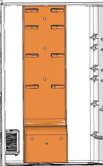
60 Disassembly of Classic Ege 70 cm and 4-Door models Disassembly of Fridge Multiflow 1. Remove the drawers and shelves from the fridge cavity. 2. Remove the 2 screws securing the Divider in the Fridge Cavity. 3. Pull on the Divider to take it out of the Fridge Cavity. 4. Remove the 5 plugs covering the screws. 5. Remove the 5 screws fixing the multiflow 6. Move the multiflow forward slightly and disconnect the damper connector. 7. Pull the multiflow right out. 8. Separate the polystyrene from the plastic cover, taking great care not to break it 2 1 N.B.: The damper must be replaced together with the polystyrene so that during reassembly no surfaces are left inadequately sealed, allowing leakage of air and potentially impairing the performance of the fridge cavity. 3 59


61 Disassembly of Classic Ege 70 cm and 4-Door models Disassembly of Fridge Multiflow 1. Remove the drawers and shelves from the fridge cavity. 2. Remove the 2 screws securing the Divider in the Fridge Cavity. 3. Pull on the Divider to take it out of the Fridge Cavity. 4. Remove the 5 plugs covering the screws. 5. Remove the 5 screws fixing the multiflow 6. Move the multiflow forward slightly and disconnect the damper connector. 7. Pull the multiflow right out. 8. Separate the polystyrene from the plastic cover, taking great care not to break it N.B.: The damper must be replaced together with the polystyrene so that during reassembly no surfaces are left inadequately sealed, allowing leakage of air and potentially impairing the performance of the fridge cavity. 8 60


62 Disassembly of Classic Ege 70 cm Disassembly of Freezer Multiflow: 1. Remove the freezer cavity drawers 2. Remove the 6 screws fixing the multiflow. 3. Pull gently on the bottom of the multiflow to remove it. 4. Open the connectors cover by pressing on the fixing clips. 5. Pull the connectors out. 1 The whole Freezer Multiflow assembly can now be removed


63 Disassembly of 4-Door Ege 70 cm models Disassembly of freezer multiflow: 1. Take out the drawers from the top and bottom of the Freezer Cavity (the disassembly procedure is similar to the latest 4-door appliances). 2. Remove the 6 screws fixing the multiflow. 3. Pull gently on the bottom of the multiflow to remove it. 4. Open the connectors cover by pressing on the fixing clips. 5. Pull the connectors out. The whole Freezer Multiflow assembly can now be removed


64 Disassembly/Opening EGE 70 & 4D Freezer Multiflow Disassembly of freezer evaporator: 1. Remove the 4 screws securing the polystyrene to the backplate. 2. Being careful not to split the polystyrene, take it off the backplate. 3. Remove the adhesive tape over the top part of the polystyrene. 4. Open the cover to obtain access to the fan. N.B.: The fan and the white frame are handled as a single replacement unit. THEY DO NOT NEED TO BE DISMANTLED!!! 63

65 Disassembly Carinaro Built In 64


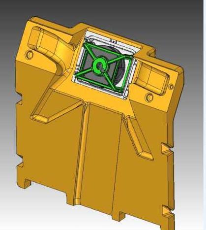
66 Disassembly of CARINARO Built In Appliances: Removing the Fan 1. Remove the 2 plugs covering the screws. 2. Remove the 2 screws securing the fan. 3. Unplug the fan from its power supply


67 Disassembly of CARINARO Built In Appliances: Disassembly of Ozone Generator: 1. Remove the 2 screws securing the ozone generator. 2. Unplug the ozone generator from its power supply. 1 Important: Don't forget that the ozone generator is a single unit and must be replaced as a whole. 2 66


68 Disassembly of CARINARO Built In Appliances: Disassembly of Freezer Cavity: 1. Remove the lower drawer. 2. Unscrew the 4 screws securing the door to the upper compartment of the freezer cavity. 3. Take off the door and the grille. 4. Unscrew the 3 screws on the front panel of the freezer cavity. 5. Unscrew the remaining 2 screws securing the evaporator cover. 6. Open the evaporator area. 7. Disconnect the fan/heating element connector. 2 N.B.: All components will now be accessible. 1 67


69 Disassembly of CARINARO Built In Appliances: Disassembly of Freezer Cavity: 1. Remove the lower drawer. 2. Unscrew the 4 screws securing the door to the upper compartment of the freezer cavity. 3. Take off the door and the grille. 4. Unscrew the 3 screws on the front panel of the freezer cavity. 5. Unscrew the remaining 2 screws securing the evaporator cover. 6. Open the evaporator area. 7. Disconnect the fan/heating element connector. N.B.: All components will now be accessible


70 Disassembly of CARINARO Built In Appliances: Disassembly of Freezer Cavity: 1. Remove the lower drawer. 2. Unscrew the 4 screws securing the door to the upper compartment of the freezer cavity. 3. Take off the door and the grille. 4. Unscrew the 3 screws on the front panel of the freezer cavity. 5. Unscrew the remaining 2 screws securing the evaporator cover. 6. Open the evaporator area. 7. Disconnect the fan/heating element connector. 7 N.B.: All components will now be accessible. 69
Essentia Project Artica Platform No Frost 60 cm Appliances 2011
 Essentia Project Artica Platform No Frost 60 cm Appliances 2011 Event Ca Maiano, May 2011 Presenter Piotr Kelm Francesco Nieli 0 Legend and User Interface Legend THR3 Interface (SQG_CL_32) MID Indesit
Service Information HOTPOINT BUILT-IN FRIDGE FREEZERS. Indesit Company UK Ltd HM31AAE KM31AAE 79819
 5407708 Issue 1 Jan. 2013 SM003557 ~ C00293951 HOTPOINT BUILT-IN FRIDGE FREEZERS ACTIVE OXYGEN ENERGY BAND A+ MODELS Models Covered Comm. Code HM31AAE 77896 KM31AAE 79819 Service Information Indesit Company
Service Quick Guide SQG_CL_15/01_EN
 Service Quick Guide SQG_CL_15/01_EN Indesit Company, Service Department Table - New Platform 2005 Electronic Refrigerators, combination and double-door 1 LED1 LED2 LED3 2 Table 1 In the case of the Led
SERVICE MANUAL New Electronic Cold Platform 2005.
 SERVICE MANUAL New Electronic Cold Platform 2005. All the parts included in this document are the property of Indesit Company S.p.A. All rights reserved. This document and the information it contains are
SERVICE MANUAL REFRIGERATION
 SERVICE MANUAL REFRIGERATION ELECTROLUX ZANUSSI S.p.A. Publication No. Spares Operations Italy 599 35 40-29 Corso Lino Zanussi, 30 020806 I - 33080 PORCIA / PN (ITALY) ITZ/SERVICE/AA EUROFLEC With exposed
SERVICE MANUAL REFRIGERATION
 SERVICE MANUAL REFRIGERATION ELECTROLUX HOME PRODUCTS S.p.A. Publication no. Spares Operations Italy 599 37 75-07 Corso Lino Zanussi, 30 060824 I - 33080 PORCIA / PN (ITALY) ITZ/SERVICE/AA Fax +39 0434
SERVICE MANUAL REFRIGERATION
 SERVICE MANUAL REFRIGERATION Electrolux Home Products S.p.A. Spares Operations Italy Corso lino Zanussi, 30 I - 33080 Porcia (PN) Fax +39 0434 394096 S.O.I. Edition: 10.2006 Publication no. 599 38 38-50
KitchenAid Food Stream Solutions Classic and Integrated Series
 KitchenAid Food Stream Solutions Classic and Integrated Series KitchenAid Chapter list Installation Range overview Installation General Information Function Compressor Power Control Board Defrosting Heating
4. ALIGNMENT AND ADJUSTMENTS
 4-1) Forced Operation Function (Pull-down / Refrigerator Defrost / Refrigerator. Freezer-Defrost / Cancellation) 28 4-2) Sound function 29 4-3) Exhibition Function 29 4-4) Self-Diagnostics Function29 4-5)
TABLE OF CONTENTS REFRIGERATOR-FREEZER. Model No. NR-BN34FX1 Model No. NR-BN34FW1
 Order Number GORR1405001CE REFRIGERATOR-FREEZER Model No. NR-BN34FX1 Model No. NR-BN34FW1 Product-Color X:Stainless W:White Destination E(Europe Continental) B(U.K.) TABLE OF CONTENTS PAGE 1 Safety Precautions-----------------------------------------------
Refrigerator KE T
 Refrigerator KE 680-1-3T Service Manual: H8-74-07 Responsible: U. Laarmann KÜPPERSBUSCH HAUSGERÄTE AG E-mail: uwe.laarmann@kueppersbusch.de Tel.: (0209) 401-732 Customer Service Fax: (0209) 401-743 Postfach
Service Information. WNes 2956 appliance documentation. Service Information no. 27/2004 LHG/TKD-Fe/June SI
 After Sales Service International Service Information Service Information no. 27/2004 LHG/TKD-Fe/June 2004 WNes 2956 appliance documentation Page 1/26 Contents 2.0. Extract from Operating Instructions
4. Alignment and Adjustments
 . Alignment and Adjustments -) Forced Operation Function (Pull-down / Refrigerator Defrost / Refrigerator. Freezer-Defrost / Cancellation) 3 -) Self-Diagnostics Function 3-3) Load Operation Check Function
Owner's Manual TABLE OF CONTENTS
 40MAQ High Wall Ductless System Sizes 09 to 36 Owner's Manual TABLE OF CONTENTS PAGE A NOTE ABOUT SAFETY... 2 GENERAL... 2 PART NAMES... 3 FUNCTION BUTTONS... 4 DISPLAY PANELS... 5 REMOTE CONTROL... 6
Before using your air conditioner, please read this manual carefully and keep it for future reference. ACDC12B
 Before using your air conditioner, please read this manual carefully and keep it for future reference. ACDC12B INVERTER SPLIT-TYPE ROOM AIR CONDITIONER User and Remote Control Manual Read This Manual Inside
Side-by-side combined refrigerator-freezer
 REPAIR INSTTRUCTTI I IONS Side-by-side combined refrigerator-freezer 1 SAFETY... 2 4.1 Electronic controller... 8 1.1 Safety instructions... 2 1.2 Repair instructions... 2 2 INSTALLATION... 3 3 OPERATION...
BFFF HUY. Partial Frost-free Bottom Combi Nyíregyháza Factory
 BFFF HUY Partial Frost-free Bottom Combi Nyíregyháza Factory Nyíregyháza Factory Electrolux Code HUY Nyíregyháza HUY Satu Mare ROA Jászberény HUC Product Range HUY HUY production: bottom combis Convenience
Part. Test System Weekly See Watch ~Test. Points
 Part 1. Test System Weekly See Watch ~Test Points 2. 3. 4. 5. 6. 7. 8. Turn System Off Enter your passcode to turn the system off and silence alarms. Turn System All On Press 9 Exit Delay begins If Error
UPS BATTERY TEST. Testing the UPS Battery (Verification Test) Locking models: 13/19/22-USGF, 13/19/22- USGR, 43/44-UDGR, 43/44-UDGF
 Locking models: 13/19/22-USGF, 13/19/22- USGR, 43/44-UDGR, 43/44-UDGF") 30 Armstrong Ave. Georgetown. Ont, L7G 4R9, Canada Tel: 800 800 5706 or 905 702 1441 Fax: 905 702 1442 www.minusforty.com SUBJECT: MODELS: UPS BATTERY TEST Testing the UPS Battery (Verification Test) Locking
30 Armstrong Ave. Georgetown. Ont, L7G 4R9, Canada Tel: 800 800 5706 or 905 702 1441 Fax: 905 702 1442 www.minusforty.com SUBJECT: MODELS: UPS BATTERY TEST Testing the UPS Battery (Verification Test) Locking
Fast Track Troubleshooting
 Fast Track Troubleshooting Model: RH22** Bulletins: IMPORTANT SAFETY NOTICE For Technicians Only This service data sheet is intended for use by persons having electrical, electronic, and mechanical experience
OWNER S MANUAL. High-Wall Fan Coil Unit CONTENTS
 OWNER S MANUAL High-Wall Fan Coil Unit Page GENERAL 2,3 OPERATING MODES 2 REMOTE CONTROL 2 OPERATION 3-9 REMOTE CONTROL OPERATION 3 INDOOR UNIT DISPLAY 5 EMERGENCY OPERATION 5 PRESSING THE ON/OFF BUTTON
Owner's Manual TABLE OF CONTENTS
 40MB*D Ducted Style Ductless System Sizes 09 to 48 Owner's Manual TABLE OF CONTENTS PAGE A NOTE ABOUT SAFETY... 2 GENERAL... 2 PARTS LIST... 3 DISPLAY PANELS... 4 FUNCTION BUTTONS... 5 REMOTE CONTROL...
Fast Track Troubleshooting
 Fast Track Troubleshooting Models Covered: RF266AD**/XAA French Door Refrigeration IMPORTANT SAFETY NOTICE For Technicians Only This service data sheet is intended for use by persons having electrical,
OWNER'S MANUAL R-410A Duct Free Split System Air Conditioner and Heat Pump
 R-10A Duct Free Split System Air Conditioner and Heat Pump Product Family: DFF(A/H)H, DFC(A/H) Please read the operating instructions and safety precautions carefully and thoroughly before installing and
BTU Units WORKING PROGRAM MANUAL
 9000-24000BTU Units WORKING PROGRAM MANUAL SUMMARIZE FUNCTIONS & OPERATION MODES TIMER, SLEEP MODE, FAN SPEED PROTECTION FUNCTIONS EMERGENCY SWITCH TEST GUIDE MEMORY FUNCTIONS SUMMARIZE The Operation Modes
Total Connect Box. User manual
 Total Connect Box User manual 1 Congratulations on your purchase of the Honeywell Total Connect Box security system. To make the best out of your system we advise you to read this manual carefully. This
User instructions DHP-AT
 User instructions DHP-AT VUGFC202 If these instructions are not followed during installation and service, Danfoss A/S liability according to the applicable warranty is not binding. Danfoss A/S retains
DLFEHA. OWNER S MANUAL High Wall Ductless System Sizes 09 to 24 TABLE OF CONTENTS
 DLFEHA OWNER S MANUAL High Wall Ductless System Sizes 09 to 24 TABLE OF CONTENTS PAGE A NOTE ABOUT SAFETY... 2 GENERAL... 2 PART NAMES... 3 INDOOR UNIT DISPLAY INDICATOR... 3 REMOTE CONTROLLER... 3 FUNCTION
SERVICE INSTRUCTION. DYNAMIC COOLING with 0 zone REFRIGERATION. Fridge/freezer with. Publication number
 SERVICE INSTRUCTION REFRIGERATION DISTRIPARTS AB BOX 501 S-562 80 NORRAHAMMAR Phone 036-31 80 00 Telefax 036-31 81 10 Telefax 036-31 80 88 Publication number 599 51 96-71 Rev. 04-04-20 SV/SERVICE DT/MA/AN
Owner s Manual TABLE OF CONTENTS
 40MBDQ Ducted Style Ductless System Sizes 18 to 48 Owner s Manual TABLE OF CONTENTS PAGE A NOTE ABOUT SAFETY... 2 GENERAL... 2 PARTS LIST... 3 DISPLAY PANELS... 4 FUNCTION BUTTONS... 5 REMOTE CONTROL...
Model Number Nomemclature... 1 Specifications... 3 Refrigeration System... 4 Freezer and Refrigerator Air Circulation... 5 Display Designs...
 Samsung AD Refrigerator Familiarization Maytag Technical Training Services 2004 ABS-L2004-012 Model Number Nomemclature... 1 Specifications... 3 Refrigeration System... 4 Freezer and Refrigerator Air
Operating Instructions REFRIGERATOR/FREEZER COMBINATION
 FFU4DG X MTZ English Operating Instructions REFRIGERATOR/FREEZER COMBINATION Operating Instructions, 1 Assistance, 2 Description of the appliance,3 Description of the appliance, 4 Installation, 5 Start-up
OWNER S MANUAL. R 410A Ductless Split System Air Conditioner and Heat Pump
 R 410A Ductless Split System Air Conditioner and Heat Pump Models DLC4(A/H) Outdoor Unit, DLF4(A/H) Indoor Unit Sizes 9K, 12K, 18K, 24K, 30K and 36K Please read the operating instructions and safety precautions
INSTRUCTION MANUAL PORTABLE FRIDGE/FREEZER. Models: RVX-35 / RVX-45 / RVX-50 RVX-55 / RVX-65 / RVX-75
 INSTRUCTION MANUAL PORTABLE FRIDGE/FREEZER Models: RVX-35 / RVX-45 / RVX-50 RVX-55 / RVX-65 / RVX-75 PLEASE READ THIS INSTRUCTION MANUAL CAREFULLY BEFORE CONNECTING AND OPERATING THE APPLIANCE. SAVE IT
PC71 American Style Fridge Freezer
 PC71 American Style Fridge Freezer Installation, Use and Maintenance Customer Care Department The Group Ltd. Harby Road Langar Nottinghamshire NG13 9HY T : 01949 862 012 F : 01949 862 003 E : customer.care@cda.eu
Heat Pump Defrost Board Replacement Kit
 Bard Manufacturing Company, Inc. Bryan, Ohio 43506 8620-223 Heat Pump Defrost Board Replacement Kit KIT FEATURES This kit is made up of the current defrost control board 8201-129 and a new defrost sensor.
Products documentation (REVISION DATE: 03/10/2011) OMFP6010 (60cm PIROLITIC OVEN)
 OMFP6010 (60cm PIROLITIC OVEN)") Products documentation (REVISION DATE: 03/10/2011) OMFP6010 (60cm PIROLITIC OVEN) Ovens Service Manual Models OMFP6010 CONTENTS This document has been published to be used for service only. The contents
Products documentation (REVISION DATE: 03/10/2011) OMFP6010 (60cm PIROLITIC OVEN) Ovens Service Manual Models OMFP6010 CONTENTS This document has been published to be used for service only. The contents
Refrigeration. Bosch pioneers in design and energy conservation to produce a range of innovative refrigeration products to suit every need.
 Bosch pioneers in design and conservation to produce a range of innovative refrigeration products to suit every need. As well as being pioneers in product design, our commitment to the environment led
Fast Track Troubleshooting
 Models Covered: RF266AA**/XAA RF266AB**/XAA RF266**/XAA French Door Refrigeration NOTICE: RF266AA & AB** 01/09 Parts Change: Refer to bulletin. All Water Tank Parts Forced Mode: Press the Pwr Freeze Fridge
Follett Performance Plus
 Follett Performance Plus touchscreen user guide The next level of control in undercounter refrigeration Controller Operation - Performance Plus touchscreen Use and care of the LCD Performance Plus touchscreen
Slim Line Ceiling Concealed Ducted Split Systems
 Miraco R 0-40V ~ 50Hz 1Ph 380-40V ~ 50Hz 3Ph MSP Medium Static Pressure Slim Line Ceiling Concealed Ducted Split Systems 53QDMT 1-18-4-30-36-4-48-60 Heat Pump OWNER S MANUAL Carrier is committed to continuously
B-764 FULL NF REFRIGERATOR CONTROL SPECIFICATIONS
 B-764 FULL NF REFRIGERATOR CONTROL SPECIFICATIONS 1 Page 1 of 30 HISTORY SHEET Date of Issue 29.11.2004 Prepared by Ferkan GULBAS Approved by Emre ARISOY Revisions. Rev. # Revised page(s) Revision and
Total Protection Alarm System
 Total Protection Alarm System SMARTHOME #7307 PAT. D410633 Patents Pending Your Guide to the Total Protection Alarm System SMARTHOME #7307 2 TABLE OF CONTENTS PACKAGE CONTENTS...4 OVERVIEW...5 PLANNING
Fast Track Troubleshooting
 Fast Track Troubleshooting Models Covered: RF197ACPN French Door Refrigeration IMPORTANT SAFETY NOTICE For Technicians Only This service data sheet is intended for use by persons having electrical, electronic,
Owner s Manual TABLE OF CONTENTS
 40MHH High Wall Ductless System Sizes 09 to 24 Owner s Manual TABLE OF CONTENTS PAGE A NOTE ABOUT SAFETY... 2 GENERAL... 2 PART NAMES... 3 INDOOR UNIT DISPLAY INDICATOR... 4 REMOTE CONTROL... 4 FUNCTION
2 INSTALLATION OPERATION FUNCTIONS SAFETY Compressor Compartment... 10
 REPAIR INSTTRUCTTI I ION REFFRI IGERATTOR 1 SAFETY... 3 4.1 Compressor Compartment... 10 2 INSTALLATION... 4 4.2 Fridge Evaporator Compartment... 11 4.3 Freezer Evaporator Compartment... 12 3 OPERATION...
Fast Track Troubleshooting
 Fast Track Troubleshooting Models Covered: RF195AC**/XAA RF197AC**/XAA RF217AC**/XAA IMPORTANT SAFETY NOTICE For Technicians Only This service data sheet is intended for use by persons having electrical,
Rev B, 9/2/2009. Kodiak Chiller Overview
 930-0001 Rev B, 9/2/2009 Kodiak Chiller Overview Presentation Outline Phone: 781-933-7300 Lytron Technical Support Contact Information 3 Introduction 4 Part I: Unpacking 5 Part II: Installation 7 Part
Dryer Controller M720
 User Manual Dryer Controller M720 Hardware version 2.00 Software version 2.00 Manual M720 Dryer controller Page 1 of 60 Document history Preliminary version: - Created in April, 2009 Hardware Version 2.00,
Installation Instructions
 Installation Instructions Sabbath Mode Product Kit ZSAB1 For Use With Monogram Built-In s: 36", 42" & 48" Side-by-Side R Models (Manufactured On or After February 2004) and X Models 36" Bottom-Freezer
Service Documentation
 After Sales Service International Service Documentation Service Manual No. 22/2008 Version 01 LHG/KDT-Ne/30.08.10 Appliance Documentation SBSes 7273 from Index 20 PremiumPlus comprising: SKBes 4212 from
Technical Training Prodigy Undercounter Cubers. Models CU1526, CU2026 and CU3030
 Technical Training Prodigy Undercounter Cubers Models CU1526, CU2026 and CU3030 List of Major Topics Introduction Installation Operation Maintenance Diagnosis Service Prodigy with a Bin 3 models CU1526
DIGITAL LIGHT CONTROLLER
 DIGITAL LIGHT CONTROLLER Manual - Model UD 0900 Modular lighting controller for 20 HPS or MH lamps Reading this manual will help you better understand the functions of your device and its potential. Keep
NookBox Installation Guide Keypad. Installation Guide. NookBox Keypad (P / E )
") 1 Installation Guide NookBox Keypad (P119010 / E6309744) 2 NookBox Keypad (P119010 / E6309744) 3 Parts Identification 1. Active LED 2. Status LED 3. Fault Display LED 4. Arm Key 5. Home Key 6. Key Check
1 Installation Guide NookBox Keypad (P119010 / E6309744) 2 NookBox Keypad (P119010 / E6309744) 3 Parts Identification 1. Active LED 2. Status LED 3. Fault Display LED 4. Arm Key 5. Home Key 6. Key Check
Indesit Company. Multiplo 2008 Jaeger Platform. Fabriano, May 2008
 Indesit Company Multiplo 2008 Jaeger Platform Fabriano, May 2008 1 Legend Multiplo F Flush Product name Multiplo SF Semi-flush 2 Interfaces REAR WELL FRONT WELL PROGRAMMED COOKING ZONE REAR COOKING ZONE
CONGRATULATIONS FF.584L.SBS.SS
 CONGRATULATIONS FF.584L.SBS.SS Dear Customer, Thank you for purchasing our Vogue Refrigerator. We are sure you will find your new appliance a pleasure to use. Before you use the appliance, we recommend
INVERTER 9-12 DC INVERTER 9 SF
 INVERTER 9-12 DC 1. TECHNICAL DATA: DESCRIPTION OF PARAMETERS INVERTER 9 SF INVERTER 9 HP INVERTER 12 SF INVERTER 12 HP Cooling capacity (1) (min / rated / max) kw 1.4/2.3/2.7 1.4/2.3/2.7 1.8/2.7/3.1 1.8/2.7/3.1
Service Information. HOTPOINT SIDE-BY-SIDE FRIDGE FREEZERS (7 ~ Segment Version) Indesit Company UK Ltd
 Indesit Company UK Ltd") 5407399 Issue 2 March 2011 HOTPOINT SIDE-BY-SIDE FRIDGE FREEZERS (7 ~ Segment Version) Models Covered Comm. Code Energy Band 'A' Models MSZ801DF 48862 MSZ802DF 46196 MSZ803DF 48863 MSZ806DF 57217 Service
5407399 Issue 2 March 2011 HOTPOINT SIDE-BY-SIDE FRIDGE FREEZERS (7 ~ Segment Version) Models Covered Comm. Code Energy Band 'A' Models MSZ801DF 48862 MSZ802DF 46196 MSZ803DF 48863 MSZ806DF 57217 Service
Fast Track Troubleshooting
 Fast Track Troubleshooting Models Covered: RS263BBBB/XAA RS263BBSH/XAA RS263BBWP/XAA RS265LBBP/XAA RS265LBWP/XAA SxS Refrigeration Notice: Bulletin on parts change Thermal Fuse to Bi-Metal Publication
Clock Radio AJ100. User manual
 Clock Radio AJ100 User manual 1 1 2 5 6 3 4 7 8 9! @ # $ % 0 ^ 2 3 4 English SUPPLIED ACCESSORIES 1 X AC 7.5V adapter (Input: 220-230V ~ 50Hz 30mA, Output: 7.5V 250mA) TOP AND FRONT PANEL (See 1) 1 REPEAT
Automatic Phone-Out Home Monitoring Systems
 Automatic Phone-Out Home Monitoring Systems Power Outage, Freeze and Flood Alarm Product Description Model Number: THP201 These monitoring systems are intended to monitor homes, cabins, and other premises
Quick Guide. Carefully read the user handbook provided before using the appliance. Refrigerator Compartment 1. Control panel
 Product sheet Quick Guide Carefully read the user handbook provided before using the appliance. Refrigerator Compartment 1. Control panel 14 1 2 3 6 5 4 7 8 9 10 11 12 13 15 17 16 2. Main LED s lighting
User Manual. Dryer Controller M720
 User Manual Dryer Controller M720 Hardware version 1.00 Software version 1.00 Preliminary version Manual M720 Dryer controller Page 1 of 42 Document history Preliminary version: - Created in April, 2009
1.1 Setup Installation
 Page 1 of 7 Author: Reviewer: QA Approval: Date: Date: Date: A. OBJECTIVE This document describes the operation of the Sanyo Ultra-Low Temperature Freezer in The University of Iowa Dezii Translational
OPERATING MANUAL Enertronic Control System 2
 OPERATING MANUAL Enertronic Control System 2 The integrated control system for Lennox chillers in the Ecologic range Manufacturer: Lennox Benelux B.V. Postbus 1028, 3860 BA NIJKERK Watergoorweg 87, 3861
HT-2 / 9600 Series Control Contents
 HT-2 / 9600 Series Control Contents Tools & Parts Tools Required Parts Required Error Messages 3 Flashing Dots Pressure or Flow Switch Not Activated Pressure or Flow Switch Activated Temperature Sensor
LeakSafe. solutions. WaterSwitch2. Installation Instructions
 LeakSafe solutions TM WaterSwitch2 Installation Instructions WATERSWITCH2 COMPONENTS WaterSwitch2 Valve Control Extended Range Valve Driver Valve Water Flow Sensor Leak Detection tape available in 0.3M
User Guide ems25plus. Page 1. Normal operation. Product interface
 Page 1 Product interface rmal operation During normal operation, EMS controllers display the information below. Assuming the product temperature is correct when the outlet is open, this means that the
Instruction Manual for Electric Ovens OO757X OO986X
 Instruction Manual for Electric Ovens OO757X OO986X 1 2 DEAR CUSTOMER, We thank you and congratulate you on your choice. This new carefully designed product, manufactured with the highest quality materials,
OWNER S MANUAL DLFCAB / DLFCHB / DLFDAB / DLFDHB High Wall Ductless System Sizes 09 36
 OWNER S MANUAL DLFCAB / DLFCHB / DLFDAB / DLFDHB High Wall Ductless System Sizes 09 36 TABLE OF CONTENTS PAGE SAFETY PRECAUTIONS... 2 GENERAL... 2 INDOOR UNIT PART NAMES... 3 REMOTE CONTROL PART NAMES...
Wireless Remote Controller Kit
 OPERATION MANUAL Wireless Remote Controller Kit L BRC7E88 Read these instructions carefully before installation. Keep this manual in a handy place for future reference. This manual should be left with
Wireless Keypad GKP-S8M
 Wireless Keypad GKP-S8M User manual Contents Congratulations on your purchase of this Honeywell wireless keypad. To make the best out of your equipment we advise you to read this manual carefully. This
Commercial Series. Power switch & Nameplate location: NAMEPLATE: Single and Dual Section
 COMMERCIAL SERIES Commercial Series Commercial Series Power switch & Nameplate location: NAMEPLATE: Single and Dual Section Must reach over behind Front Panel to access: Single and Dual Section Commercial
Fast Track Troubleshooting
 Fast Track Troubleshooting Publication # tsrs265td Revision Date 03/30/2011 Models Covered: RS265TDBP/XAA RS265TDPN/XAA RS265TDRS/XAA RS265TDWP/XAA IMPORTANT SAFETY NOTICE For Technicians Only This service
IKS..10,..20 / IK..00 / EK..10 from Index 20. IKS..14,..24 / IK..04 / EK..14 from Index 20, with 4-star freezer compartment
 After Sales Service International Service Information No. 03/2006 Service Information LHG/TKD-Ne/06.04.06 Appliance Documentation IKS..10,..20 / IK..00 / EK..10 from Index 20 IKS..14,..24 / IK..04 / EK..14
Owner s Manual TABLE OF CONTENTS
 40MBD / 38MAQ / 38MBQ Ducted tyle Ductless plit ystem izes 09 to 48 Owner s Manual TABLE OF CONTENT PAGE A NOTE ABOUT AFETY... 2 GENERAL... 2 PART LIT... 3 DIPLAY PANEL... 4 REMOTE CONTROL... 6 REMOTE
CONTROL PANEL INSTRUCTIONS RSQ-4
 CONTROL PANEL INSTRUCTIONS RSQ-4 FOR SIRAC AIR TO WATER HEAT PUMP (SINGLE COMPRESSOR, AIR TO WATER) 1) System Configuration This system is composed of mainboard and wire control panel. 146mm Φ4 4 Mainboard
TECHNICAL SERVICE BULLETIN
 WARNING READ THIS SECTION IN ITS ENTIRETY AND FOLLOW OUTLINED INSTRUCTIONS BEFORE OPERATING THE UNIT. IN THE EVENT THE ELECTRONIC SAFETY LOCK HAS LOCKED THE UNIT, THE FOOD IN THE UNIT MUST BE INSPECTED
Due to a possibility of personal injury or property damage, always contact an authorized technician for service or repair of this refrigerator.
 Bottom Mount Refrigerator Technical Information Due to a possibility of personal injury or property damage, always contact an authorized technician for service or repair of this refrigerator.! CAUTION
SPLIT TYPE. Instruction manual
 SPLIT TYPE Instruction manual ENGLISH Instruction manual Page 1~24 To obtain the best performance and ensure years of trouble free use, please read this instruction manual completely. 1 SAFETY PRECAUTION
Fire Command Keypad. XR5 User s Guide
 Fire Command Keypad XR5 User s Guide Silencing an Alarm While the fire alarm horns, strobes, or sirens are sounding use one of the following methods to silence the alarm depending on which type of keypad
CD Clock Radio AJ3915. User manual Manuel d'utilisation Manual del usuario Gebruikershandleiding
 CD Clock Radio AJ3915 Register your product and get support at www.philips.com/welcome User manual Manuel d'utilisation Manual del usuario Gebruikershandleiding 1 1 2! 3 @ 4 3 5 6 7 8 9 0 TUNING # $ %
Prodigy Plus - D Series Cuber Technical Review
 Prodigy Plus - D Series Cuber Technical Review Water Distributor Control Panel Air Filter ice Thickness Sensor Lower Light and Switch Panel Water Pump Water Level Sensor & Guard Curtain Switch and Magnet
WORKING PROGRAM. Heating dehumidifying cooling T 27
 I. Functions and Operation Modes WORKING PROGRAM The operation modes of the unit run like the following: Auto cooling dehumidifying heating --------------------------------------- Note: Cooling only unit
SERVICE MANUAL. Inverter Wall Mounted Single Split. MODELS Cooling Only. Heatpump SM-5WM-Y-NA-B1
 SERVICE MANUAL Inverter Wall Mounted Single Split MODELS Cooling Only FTKB09AXVJU FTKB12AXVJU FTKB18AXVJU FTKB24AXVJU FTKN09AXVJU FTKN12AXVJU FTKN18AXVJU FTKN24AXVJU Heatpump FTXB09AXVJU FTXB12AXVJU FTXB18AXVJU
The Kryos LN2 Liquid Level Control & Cryogenic Temperature Control
 The Kryos LN2 Liquid Level Control & Cryogenic Temperature Control Created for Taylor-Wharton Gas Equipment By Pacer Digital Systems, Inc. INTRODUCTION... 4 TEXT FORMAT NOTATION... 4 SYSTEM COMPONENTS...
CS027 User Instructions
 CS027 User Instructions Battery Powered 7 Day Programmable Room Thermostat Programmable room thermostats are widely recognised as one of the best ways in which to control central heating. The CS027 programmable
Frost Checklist and Troubleshooting Guide for NDA1402 & NEA1402
 Frost Checklist and Troubleshooting Guide for NDA1402 & NEA1402 REFRIGERATOR BULLETIN R82-7A NOVEMBER 2007 USA SERVICE OFFICE Dometic Corporation 2320 Industrial Parkway Elkhart, IN 46516 574-294-2511
Undercounter Refrigerator Operation Manual
 Undercounter Refrigerator Operation Manual i.series and Horizon Series Model Group i.series Horizon Series Blood Bank ib105 (Version A) HB105 (Version A) Laboratory/Pharmacy ilr105 (Version A) HLR105 (Version
User s Guide. SUB-MA7240O-0001.OG.Solution doc. Created: 6/05/03. Last Updated: 23/09/03. MA7240AO-0001 Version 1.0
 User s Guide SUB-MA7240O-0001.OG.Solution40-111.doc Created: 6/05/03 Last Updated: 23/09/03 MA7240AO-0001 Version 1.0 2 Table Of Contents User List...6 Quick Reference..7 Features...7 Keypad User's Guide...8
Refrigerated air dryers
 Refrigerated air dryers OPERATING AND MAINTENANCE MANUAL Original instructions 38178800319 OPERATING AND MAINTENANCE MANUAL - Contents 1 CONTENTS CONTENTS... 1 Chapter 1 IDRY ELECTRONIC CONTROLLER...
LeakSafe. solutions. WaterSwitch2. Installation Instructions
 LeakSafe solutions TM WaterSwitch2 Installation Instructions QUICK USER GUIDE 1. Turning water ON or OFF using the WaterSwitch Valve Control To turn the water ON, press and hold down the WATER ON button
USER GUIDE. TUN6015W TUN6018W 60cm Frost Free Freezer
 USER GUIDE TUN6015W TUN6018W 60cm Frost Free Freezer Thank you for buying this high quality appliance This handbook is designed to help you through each step of owning your new appliance, from installation
IMPORTANT SAFEGUARDS Danger! Danger of burns!! Important!
 IMPORTANT SAFEGUARDS When using any electrical appliance, some basic safety precautions should always be observed to reduce the risk of fire, electric shock, and/or injury to persons. Read all instructions
Bottom Mount Refrigerator---Technical Information
 Bottom Mount Refrigerator---Technical Information WARNING Electrical Shock Hazard Disconnect power before servicing. Replace all parts and panels before operation. Failure to do so can result in death
Roth Touchline. German quality since Quick and easy user manual 1/10
 Roth Touchline Quick and easy user manual German quality since 197 1/10 230 V Pump N N L L 230 V 230 V 2 V 2 V c/o in %H c/o out c/o in Trafo out /TB in N L eco 2V CH 1 CH 2 CH 3 CH 2V 2V 2V 2V 2V Touchline,
Caliber Series LED Edgelit Exit Sign EXPORT AC Only or Emergency Operation READ AND FOLLOW ALL SAFETY INSTRUCTIONS
 Caliber Series LED Edgelit Exit Sign EXPORT AC Only or Emergency Operation INSTALLATION AND OPERATING INSTRUCTIONS IMPORTANT SAFEGUARDS When using electrical equipment, basic safety precautions should
JBL2088HES JBL2088HES0, JBR2088HES JBR2088HES0, JFC2089HEP JFC2089HEP0, JFC2089HES JFC2089HES0, JFC2089HPF JFC2089HPF0, JFC2089HPY JFC2089HPY0
 Bottom Mount Refrigerator Technical Information JBL2088HES JBL2088HES0, JBR2088HES JBR2088HES0, JFC2089HEP JFC2089HEP0, JFC2089HES JFC2089HES0, JFC2089HPF JFC2089HPF0, JFC2089HPY JFC2089HPY0 Due to a possibility
Wireless Keypads LKP(E)S8M Series
S8M Series") Wireless Keypads LKP(E)S8M Series User manual Contents Congratulations on your purchase of this Honeywell wireless keypad. To make the best out of your equipment we advise you to read this manual carefully.
Wireless Keypads LKP(E)S8M Series User manual Contents Congratulations on your purchase of this Honeywell wireless keypad. To make the best out of your equipment we advise you to read this manual carefully.
High Wall Split Systems Cool Only 9K - 12K - 18K - 24K. Auto. Auto. Fan Speed. Smart LCD Wireless Control. Auto Mode.
 HFC4 1 0 A 0-40V ~, 0Hz 1Ph High Wall Split Systems Cool Only 9K - 1K - 18K - 4K R-410A IAQ $ Auto Auto Fan Speed Timer s Easy Flexible Installation Smart LCD Wireless Control Auto Mode Auto Restart Easy