Drum Type Washing Machine
|
|
|
- Juliet McCarthy
- 5 years ago
- Views:
Transcription


1 Order No. VES CE Drum Type Washing Machine Model No. NA-127VB5WGB Model No. NA-127VB5WFR Model No. NA-127VB5WES Model No. NA-127VB5WTA Model No. NA-127VB5WPL Model No. NA-127VB5WGN Model No. NA-127VB5WNR Model No. NA-147VB5WDE Model No. NA-147VB5WGB Model No. NA-147VB5WGN Model No. NA-147VB5WNR Product Colour White Destination Germany, UK, France, Belgium, Norway, Italy, Spain, Hungary, Holland, Poland, Sweden, Denmark, Finland Panasonic Corporation 2013 Unauthorized copying and distribution is a violation of law.
2 TABLE OF CONTENTS PAGE 1 Safety Precautions Specifications Location of Controls and Components Installation Instructions Operating Instructions Test Mode Service Mode Troubleshooting Guide Critical Torque Valuess Disassembly and Assembly Instructions Component Specifications Wiring Connection Diagram Exploded View and Replacement Parts List PAGE 2
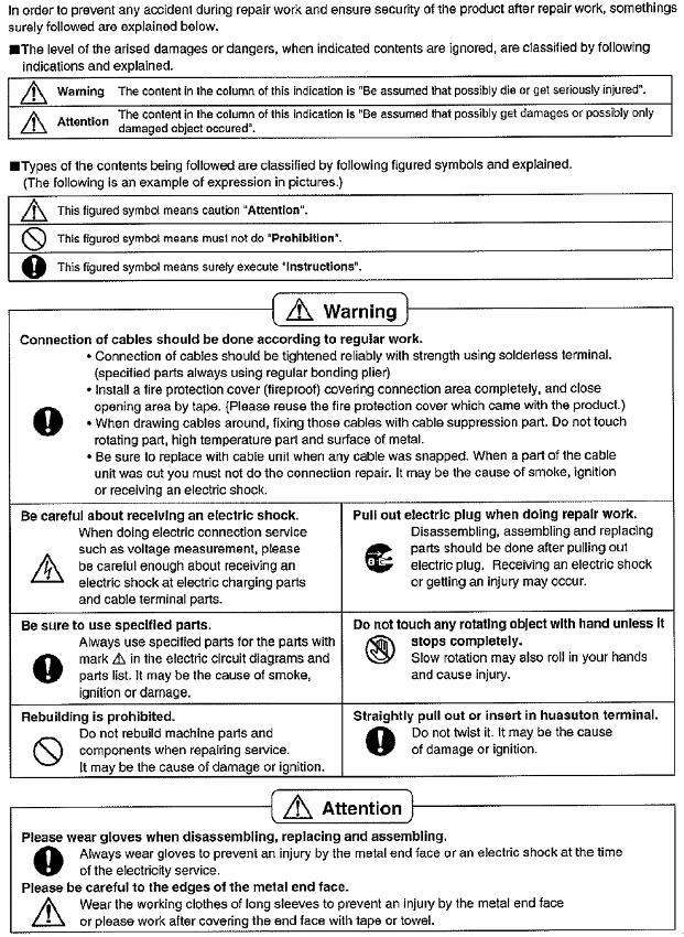
3 1 Safety Precautions 3

4 2 Specifications 2.1. Product Specifications Model NA-127VB5 NA-147VB5 Product Type Front Loader Front Loader Capacity 7 kg 7 kg Max Spin Speed 1200 rpm 1400 rpm Drum Volume 50 lt 50 lt Energy Label Rating A+++ A+++ Energy Consumption 162 kwh / annum 162 kwh / annum Water Consumption 9240 L / annum 9240 L / annum Noise Level Wash 58 dba 58 dba Spin 74 dba 76 dba Control Panel LCD Display LCD Display Wash Programs 15 settings 15 settings Spin Speed Setting 6 setting 7 setting Height 84.5 cm 84.5 cm Dimensions Width 59.7 cm 59.7 cm Depth 54.2 cm 54.2 cm Door Opening Large door opening Large door opening Delay Time Setting Yes Yes Colour White White Water Protection Overflow Protection Overflow Protection Aquastop Hose(for Germany only) Other Features Child Lock Child Lock Packaging Shrink package Shrink package 2.2. Name Plate 4

5 2.3. Dimensions NA-127VB5WGB / 127VB5WFR / 127VB5WES / 127VB5WTA / 127VB5WPL / 127VB5WGN / 127VB5WNR / Dimension in millimetres NA-127VB5, NA-147VB Twinjet Information 1. Twinjet system is designed to obtain a better washing performance by directly injecting water with detergent using a recirculation system and two nozzles connected to it. With twinjet system, water consumption is decreased by 30%, energy consumption is decreased by 10% and washing time is decreased by 15%. 2. Twinjet system is valid for all programs except spin and drain mode. The system dos not function during Water inlet, heating, spinning, drain phases. 3. Even with a large load of 8 kg. the washing machine will have the minimum energy consumption by the help of Twinjet system. 4. Washing machines with Twinjet system are very environment-friendly by having maximum washing performance with minimum water consumption. 5

6 3 Location of Controls and Components 6


7 4 Installation Instructions 4.1. Moving and Installing Removal of Transportation Screw 1. Transportation screws, which are located at the back side of the machine, must be removed before running the machine. 2. Loosen the screws by turning them anticlockwise with a suitable spanner Foot Adjustment 1. Do not install machine on rugs or similar surfaces. 2. For machine to work silently and without any vibration, it should be installed on a flat, non-slippery firm surface. Any suspended floor must be suitably strengthened. 3. You can adjust the level of machine using its feet. 4. First, loosen the plastic adjustment nut away from the cabinet base. 5. Change the level by adjusting the feet upwards or downwards. 6. After level has been reached, tighten the plastic adjustment nut again by rotating it upwards against the base of the cabinet. 7. Never put cartons, wooden blocks or similar materials under the machine to balance irregularities of the floor. 3. Pull out the screws and rubber washers. 4. The holes where the transport screws have been removed should be covered with the plastic transport caps found in the accessories bag. 5. The transportation screws that have been removed from the machine must be re-used in any future transporting of the machine Electrical Connection 1. Washing machine requires a 50Hz supply of Volts. 2. A special earthed plug has been attached to the supply cord of washing machine. This plug must be fitted to an earthed socket. The fuse value fitted to this plug should be 13 amps. If you have any doubts about electrical supply, consult a qualified electrician. THIS APPLIANCE MUST BE EARTHED. Insert the machine s plug to a grounded socket which you can easily reach. 7

8 Water Supply Connection 1. Washing machine is supplied with a single (cold) water inlet. 2. To prevent leakage from the connection joints, a rubber washer is included in the hose packing. Fit this washer at the end of water inlet hose on the tap side. 3. Connect the hose to the water inlet valve. Tighten the plastic connector by hand. Please call a qualified plumber if you are unsure about this. 4. Water pressure of 0,1-1 MPa from tap will enable machine to work more efficiently.(0,1 MPa pressure means water flow of more than 8 litres in 1 minute from a fully opened tap) 5. After connection is complete, check for leakage by turning on tap completely. 6. Make sure that water inlet hoses can not become folded, damaged, stretched or crushed when the washing machine is in its final position. 7. Mount the water inlet hose to a 3/4 threaded water tap Drain Connection 1. Make sure that water inlet hoses are not folded, twisted, crushed or stretched. 2. The drain hose should be mounted at a minimum height of 60 cm, and a maximum height of 100 cm from the floor. 3. The end of the drain hose can be connected directly to a drainage stand-pipe or alternatively to a specific connection point designed for that purpose on the waste outlet of a sink unit. 4. Do not extend the drain hose or guarantee will be invalidated Detergent Box Group 8

9 5 Operating Instructions 5.1. LCD Screen, Function Buttons & Knobs PR SW1 SW2 SW3 SW4 SW5 SW6 SW7 Program selector 16 programs including off position Switch 1, Start / Pause Switch 2, Temperature Selection Switch 3, Spin Speed Selection Switch 4, Delay Timer Selection Switch 5, Extra Rinse Option Switch 6, Easy Ironing Option Switch 7, Eco/Speed Mode Option SS1 7 Segment LCD for Temperature Display I8 Extra Rinse Symbol SS2 7 Segment LCD for Spin Speed Display I9 Easy Ironing Symbol SS3 7 Segment LCD for Remaining Time I10 Eco Mode Symbol I1 Child Lock Symbol I11 Speed Mode Symbol I2 Door Lock Symbol I12 Cold Wash Symbol I3 Drain Phase Symbol I13 Temperature Sign I4 Spin Phase Symbol I14 Program Proceeding Zone I5 Rinse Phase Symbol Slow Blink ON 0.5 sec, OFF 0.5 sec, ON 0.5 sec I6 Wash Phase Symbol Fast Blink ON 0.10 sec, OFF 0.10 sec, ON 0.10 sec I7 Delay Symbol 9

10 5.2. Program Details 10


 While")

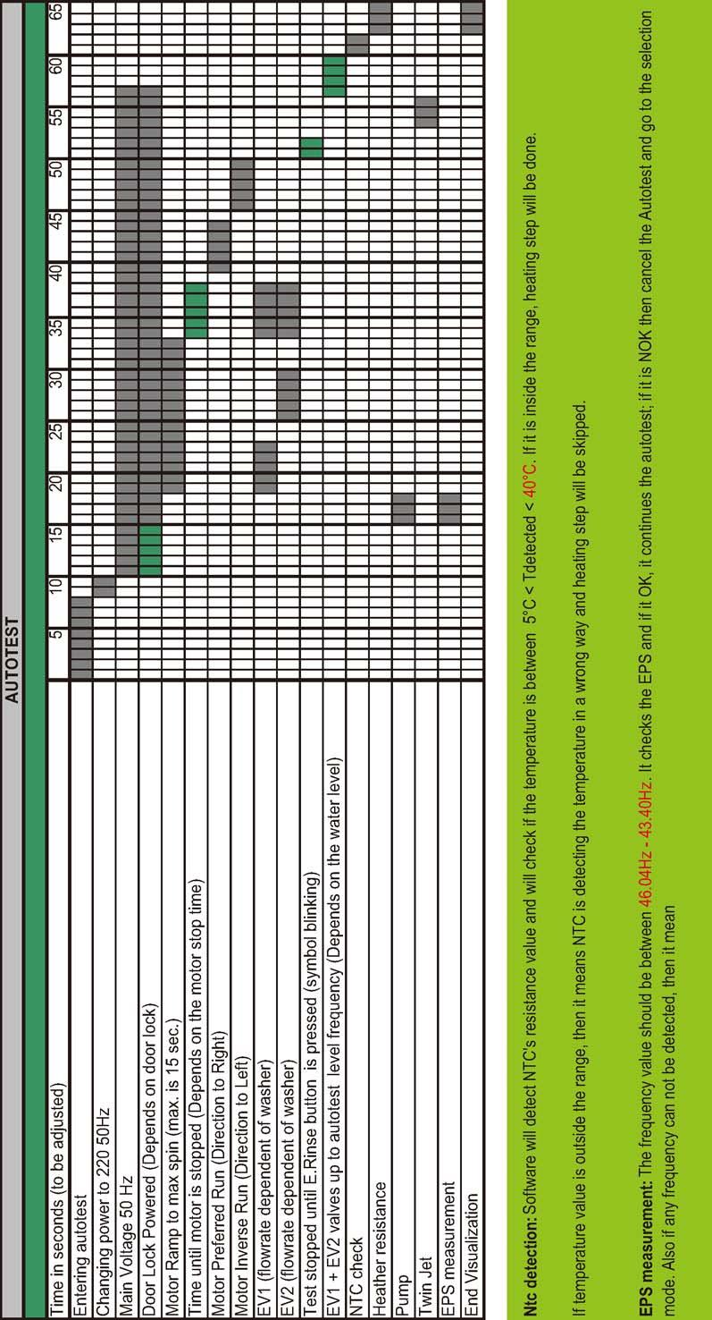
11 5.3. Child Lock Activation Press SW7 for 5 seconds. NA-127VB5WGB / 127VB5WFR / 127VB5WES / 127VB5WTA / 127VB5WPL / 127VB5WGN / 127VB5WNR / Deactivation Press SW7 for 5 seconds. The Child Lock Symbol on appears on the LCD display as Child Lock is active. The Child Lock Symbol will disappear on LCD displayupon deactivation. 6 Test Mode 6.1. Autotest Set PR to program 3 (Colours) While pressing SW5 (Extra Rinse), change position of the PR from third program to second (Cotton-Prewash), and release the SW5 after keep more than 5 seconds. Autotest starts. 11
12 12
 and press SW2 (T C) Or if the NTC connection is broken then it should give again E05 NTC failure.")
13 7 Service Mode 7.1. Service Autotest NA-127VB5WGB / 127VB5WFR / 127VB5WES / 127VB5WTA / 127VB5WPL / 127VB5WGN / 127VB5WNR / 1. Set PR to program 3 (Colours) and press SW2 (T C) Or if the NTC connection is broken then it should give again E05 NTC failure. At the end of heating, [SAU] visualization should make slow blink to indicate that the step is over. Note: If user changes the selector position, machine will do what is defined for the new selected position. 2. While pressing the SW2, change PR position from third to second, and release the SW2 after keep more than 5 seconds. Step 2: Selector Program 2 (Cotton Prewash) will be [PUMP ON] Temperature will be measured, if it is higher than 50 C, it should take 60 sec. cooling water, and then make [Drain + 5 sec.] At the end of pump activation, [SAU] visualization should make slow blink to indicate that the step is over. 3. Bring PR to desired test step (1st,2nd or 3rd program position) as soon as [SAU] is displayed on LCD. Step 3: Selector position 3 (Colours) will be a 12 mins test program where all functions of the appliance will be checked. Machine will make exactly the same algorithm of Super Rapid 12'. So, time for selector position 3 is 12 minutes. At the end of test program [End] is visualized on LCD and door is unlocked. LCD Display status: I2 Door Lock Symbol -> Fixed on SS3 -> SAU The test steps are as below ; Step 1: Selector Program 1 (Cotton) will be [HEATER ON] Before heating it should take water till first level frequency then start heating. Heater will be on max. 8 minutes after this 8 minutes if the temp. doesn t change more than 2 C then it will give NTC failure. (E05). 13
14 7.2. Failure Codes Error Indication Error Number Indication For User Indication For Service Yes/No Yes/No Door is not locked E01 Yes Yes Door is unlocked during programme E01 Yes Yes Lack of water E02 Yes Yes Pump failure E03 Yes Yes Overflow E04 Yes Yes NTC or Heater Failure E05 No Yes Motor Failure - 1 (Tachometer open-short circuit or E06 No Yes motor connector is disconnected) Motor Failure - 2 (triac short circuit) E08 No Yes Electronic Pressure Sensor E10 No Yes 8 Troubleshooting Guide All repairs which must be done on the machine should be done by authorized agents only. When a repair is required for machine or you are unable to eliminate the failure with the help of the information given below: Unplug the machine. Close the water tap. FAILURE PROBABLE CAUSE METHODS OF ELIMINATION It is unplugged. Insert the plug into the socket. Fuse is defective. Change fuse. Start / Pause button has not been Press the start / pause button. Machine does not operate. pressed. The program knob is in 0 (off) status. Bring the program knob on the desired status. The door is not shut properly. Shut the door properly. You should hear the click. Child lock is active. See section 5.3. Water tap is closed. Open water tap. The water inlet hose may be bent. Check the water inlet hose. Machine does not receive water. The ater inlet hose is obstructed. Clean the filters of water inlet hose. The water inlet filter is obstructed. Clean the valve inlet filters. The door is not shut properly. Shut the door properly. You should hear the click. The drain hose is obstructed or bent. Check the drain hose. Machine is not draining water. The pump filter is obstructed. Clean the pump filter. The clothes are not placed inside the Spread the clothes inside the machine in an orderly and machine in a well-balanced manner. well-balanced manner. The feet of machine are not adjusted. Adjust the feet. Transportation screws are not removed. Remove transportation screws. Machine is vibrating. There is a small amount of clothes in It does not prevent operation of the machine. the device. Excessive amount of clothes are filled Do not exceed the recommended quantity of clothes in the machine or the clothes are not and spared clothes in the machine in a well-balanced placed in a well-balanced manner. manner. Excessive foam in the detergent drawer The washing result is bad. The washing result is not good. The water is seen in the drum during washing. Too much detergent has been used. Press the start/pause button. In order to stop the foam, dilute one table-spoon of softener in half liter of water and pour it in the detergent drawer. Press the start/ pause button after 5-10 minutes. Arrange the amount of the detergent properly in the next washing process. Wrong detergent has been used. Use only the detergents produced for full automatic machines. Laundry too dirty for the program you Select a suitable program. have selected. The amount of detergent used is not Use more detergent according to the detergent. sufficient. Clothes exceeding the maximum Put the clothes in machine in a manner not to exceed capacity has been filled in machine. its maximum capacity. Water may be hard. Use the amount of detergent according to the declaration of the detergent producer. Distribution of the clothes in machine is Spread the clothes inside the machine in an orderly and not well-balanced. well-balanced manner. No failure. The water is at the lower part of the drum. 14
15 FAILURE PROBABLE CAUSE METHODS OF ELIMINATION The pieces of some detergents which By calibrating machine for [Rinsing] program, make an do not dissolve in water may stick to additional rinsing or eliminate the stains After drying clothes as white stains. with the help of a brush. These stains may be caused by oil, In the next washing operation, use the maximum detergent amount declared by the detergent cream or ointment. producer. There are residues of detergent on the clothes. There are grey stains on the clothes. The spinning process is not done or starts with delay. No failure. The unbalanced load control works in that way. The unbalanced load control system will try to distribute clothes in a homogenous manner. After clothes are distributed, passage to spinning process will be realized. In the next washing process, place clothes into the machine in a well-balanced manner. 15
16 9 Critical Torque Valuess Assembly Location Bolt/Nut Torque Min. (Nm) Torque Nom. (Nm) Torque Max. (Nm) Air Pressure Wrench. (rpm) * Transport Screw Assembly Transport Screws * Motor Assembly Motor Screws * Front Concrete Weight - Front Front Counterweight Screws Tub Assembly * Upper Counter Weight Assembly Upper Counterweight Screws * Pulley - Drive Shaft - Washing Pulley - Drive Shaft Assembly Group Assembly Bolt * Heater Assembly Heater Assembly Nut The bolts/nuts above are important for product safety purposes. Please tighten screw, bolts and nuts according to the torque values given in table above. 16


 4.")
17 NA-127VB5WGB / 127VB5WFR / 127VB5WES / 127VB5WTA / 127VB5WPL / 127VB5WGN / 127VB5WNR / 10 Disassembly and Assembly Instructions Top Plate 2. Pull the door up. 1. Remove two screws that fix the top-plate at the back. 2. Push the top-plate back and pull it up. 3. Remove screws that fix the door group Door 1. Remove two screws that fix the door. (by using T25 tool) 4. Put the door outside plastic with helping screwdriver. 17


18 NA-127VB5WGB / 127VB5WFR / 127VB5WES / 127VB5WTA / 127VB5WPL / 127VB5WGN / 127VB5WNR / Spring Wire 5. Remove the door inside plastic. 1. First remove the spring wire fixing the tub bellows seal by using the small size screw driver. Pull the tub bellows seal. 6. Remove six screws that fix the door hinge. 2. Remove the tub bellows seal-body fixing spring Detergent Drawer 1. Gently pull the detergent drawer. 7. Remove the door handle. 2. While pressing siphon cover keep pulling drawer to remove it. 8. Remove the door handle pin. 18


19 NA-127VB5WGB / 127VB5WFR / 127VB5WES / 127VB5WTA / 127VB5WPL / 127VB5WGN / 127VB5WNR / Control Panel 5. Remove electronic card cover as it is shown in the pictures by using small screw driver. 1. Remove the screw which fixes the control panel to the front panel Remove two screws fixing control panel Electronic Card & Fuse 3. Pull the control panel out. 1. Remove PCB box using a small screw driver. 4. Remove connectors


20 NA-127VB5WGB / 127VB5WFR / 127VB5WES / 127VB5WTA / 127VB5WPL / 127VB5WGN / 127VB5WNR / 3. Unplug display card connector Open fuse box and remove the fuse. 4. Remove the tub bellows seal Front Panel 1. Remove the screw fixing the front panel at the bottom. 5. Remove two screws fixing front panel to body. 2. Remove two screws fixing the door lock. 6. Remove the screw fixing twinjet elbow. 20


21 NA-127VB5WGB / 127VB5WFR / 127VB5WES / 127VB5WTA / 127VB5WPL / 127VB5WGN / 127VB5WNR / Detergent Drawer Housing 7. Pull front panel up. 1. Remove the tub bellow hose by releasing the holder extensions of bellow hose. 8. Remove front panel 2. Unplug connectors from feed valve Support Bracket 1. Remove two screws fixing the body group on the upper part. 3. Slightly turn the feed valve counter-clockwise to remove. 2. Remove two clips fixing detergent drawer housing to upper support bracket. 4. Remove the detergent drawer housing assembly. 21


22 NA-127VB5WGB / 127VB5WFR / 127VB5WES / 127VB5WTA / 127VB5WPL / 127VB5WGN / 127VB5WNR / Power Cable Group and EMI Filter 4. Remove EMI filter. 1. Remove the five conectors that is connected to the EMI filter Electronic (EPS) 1. Unplug EPS connector. 2. Remove two screws fixing EMI filter. 2. Pull EPS up. 3. Pull the power cable group up. 22 Pressure Switch


23 NA-127VB5WGB / 127VB5WFR / 127VB5WES / 127VB5WTA / 127VB5WPL / 127VB5WGN / 127VB5WNR / 3. Remove clamp from EPS hose. 2. Remove clamp fixing tub outlet hose. 3. Unplug drain pump connector Door Lock 1. Unplug door lock connector. 4. Remove screws holding drain pump Drain Pump 1. Remove clamp holding drain hose by using a plier Front Counterweight 1. Remove three screws on the front counterweight. (Wrench size 13 mm) 23


24 NA-127VB5WGB / 127VB5WFR / 127VB5WES / 127VB5WTA / 127VB5WPL / 127VB5WGN / 127VB5WNR / Twinjet System 2. Gently pull counterweight out. 1. Remove the tub gasket clip by using small screwdriver Heater 2. Remove twinjet hoses from tub bellow seal pulling them up. 1. Unplug heater connectors. 2. Remove nut (8 mm) fixing the heater. 3. Remove screw fixing circulation pump. 3. Pull heater out gently holding both sides. 4. Lay the appliance down and press on ratchet holding circulation pump. 24


25 NA-127VB5WGB / 127VB5WFR / 127VB5WES / 127VB5WTA / 127VB5WPL / 127VB5WGN / 127VB5WNR / 2. Hold the tub bellows seal and gasket-body fixing spring together, and pull them out. 5. Remove circulation pump. 6. Remove cable connector Transport Screw 1. Remove four transport screws. 7. Remove hose connecting circulation pump to drain pump. 2. Hold the transport screw and pull it out Tub Bellow Seal 1. Remove the tub gasket clip by using small screwdriver. 25


26 NA-127VB5WGB / 127VB5WFR / 127VB5WES / 127VB5WTA / 127VB5WPL / 127VB5WGN / 127VB5WNR / Upper Counterweight 2. Cut all the cable ties which fix cable group 1. Remove two screws fixing the upper counterweight by using box wrench size 13 mm. 3. Remove the screws fixing hanger bracket. 2. Hold and carry upper-counterweight out. 4. Remove the washing group carrying it out through front side Washing Group 1. Unplug motor connectors. 26


27 NA-127VB5WGB / 127VB5WFR / 127VB5WES / 127VB5WTA / 127VB5WPL / 127VB5WGN / 127VB5WNR / Shock Absorber Pin 2. Remove pulley. 1. Remove shock absorber pins squeezing the ratchet by a pliers Motor 1. Remove two screws holding motor by using box wrench Driven Pulley 1. Remove the belt rotating the driven pulley. 2. Pull motor up Driven Pulley 1. Remove the bolt at the center of pulley by tucking a wooden bar avoids rotation. 27


28 NA-127VB5WGB / 127VB5WFR / 127VB5WES / 127VB5WTA / 127VB5WPL / 127VB5WGN / 127VB5WNR / Tub 4. Remove 19 screws around tub using box wrench size 8 mm. 1. Remove tub inlet bellow hose loosening the clamp squeezing it by using a pliers. 5. Remove front tub. 2. Remove screw holding EPS reservoir. 6. Remove drum. 3. Remove tub outlet bellowed hose loosening screwedclamp. 11 Component tions Drain Pump 28 Specifica-


 Thermal protector YES Testing component Check the resistance value on")

29 Drain pump is both a mechanical and elektrical component which is used to drain water inside the washing machine. It has an synchronous motor inside. For better performance maintanance, pump filter should be cleaned regularly. Nominal voltage V Nominal current 0.28 A(±10 %) Nominal power 37 W Frequency 50 Hz Technical features Resistor (coil) 136 (±5%) Water flow 17 L/min (to 1 m height) Thermal protector YES Testing component Check the resistance value on the component with multimeter as shown below. Resistance value should be between You can determine the ohm value by measuring from the blue cable at 2nd and blue cable at 11th position in the large socket (refer wiring diagram in section 12) as shown below figure. Resistance value should be between Component test 29

 169,5 (±5%) Testing component Check the resistance value on the")

 as shown below")
30 11.2. Circulation Pump The component is used for circulation of water inside the drum in order to increase washing performance. Technical features Nominal voltage V Frequency 50 Hz Resistor (coil) 169,5 (±5%) Testing component Check the resistance value on the component with multimeter as shown below. Resistance value should be between You can determine the ohm value by measuring from the red cable at 5th and red cable at 12th position in the small socket (refer wiring diagram in section 12) as shown below figure. Resistance value should be between Component test 30
 is a component which is desingned to regulate temperature of water inside")
 Tubular heating element with")

")
31 11.3. Heater NA-127VB5WGB / 127VB5WFR / 127VB5WES / 127VB5WTA / 127VB5WPL / 127VB5WGN / 127VB5WNR / Heating element (Resistance) is a component which is desingned to regulate temperature of water inside the drum. It has three connections: Phase, notral and ground connections. Heater type Nominal voltage Technical features Nominal power 2000 W (±5%) Tubular heating element with NTC-sensor Resistance 24,8 ±5% 230 V Thermal fuse 2 sided Testing component Check the resistance value on the component with multimeter as shown below. Resistance value should be between 24,8 ±5% You can determine the ohm value by measuring from the grey cable at 13th and brown cable at 4th position in the small socket (refer wiring diagram in section 12) as shown in below figure. Resistance value should be between 24,8 ±5% Component test 31


32 11.4. NTC Component which sends signals to PCB about the water temperature inside the tub. The Resistance (Ohm) value of the NTC decreases as the temperature increases. Technical features Testing component Check the resistance value on the component with multimeter as shown below. You can determine the ohm value by measuring from the blackcable at 3rd and black cable at 11th position in the small socket (refer wiring diagram in section 12) as shown in below figure. NTC resistance value varies depending on temperature. Component test 32

 Nominal power 8 VA Operating water pressure 0.")


33 11.5. Valve NA-127VB5WGB / 127VB5WFR / 127VB5WES / 127VB5WTA / 127VB5WPL / 127VB5WGN / 127VB5WNR / Valve is an electrical and mechanical component which is designed to take water from the network system into the washine machine. It is operated by PCB card. Technical features Nominal voltage V Rated flow 7 L/min (±15 %) Nominal power 8 VA Operating water pressure Mpa Frequency Hz Testing component Check the resistance value on the component with multimeter as shown below. Valve water flow rate should be between 6-8 L/min. Each valve coil resistance values should be between k You can determine the resistance value of the main wash valve by measuring from the blue cable at 5th and white cable at 15th position or the pre-wash valve by measuring from the black cable at 14th and white cable at 15th position in the large socket (refer wiring diagram in section 12) as shown in below figure. Each valve coil resistance values should be between kohm. Component test 33


34 11.6. Electronic Pressure Sensor (EPS) Electromagnetic field occurs due to movement of pressurized membrane. The spring moves vertically by nucleus due to electromagnetic field. The water level is regulated according to the frequency changes of the spring by electronic card. Testing component Push the door lock slider with screwdriver. Select the 1st program and start the machine. Unplug power cable when as soon as water intake finishes and drum begins to rotate. Check the water level inside the drum with ruler. It should be 10 cm ±1. 34


35 11.7. Motor NA-127VB5WGB / 127VB5WFR / 127VB5WES / 127VB5WTA / 127VB5WPL / 127VB5WGN / 127VB5WNR / The washing machine has an asynchronous motor. It is controlled by the PCB. It is essential to check the motor for correct diagnosis and quick servicing. In the below picture, socket points on the motor is shown to measure with multimeter. Motor socket terminals Testing components Tacho resistance control Check the motor tacho terminals on the motor socket with multimeter as shown in the picture above. You can determine the ohm value by measuring from the pink cable at 16th and red cable at 6th position in the large socket (refer to section 12 Wiring Connection Diagram) as shown on right figure. For resistance values, refer to the table below. Stator Resistance Control Check the motor stator terminals on the motor socket with multimeter as shown in the picture. You can determine the ohm value by measuring from the black cable at 18th and brown cable at 8th position in the large socket (refer to section 12 Wiring Connection Diagram) as shown on right figure. For resistance values, refer to the table below. Tacho and stator resistance values of motor: 35
, the bimetal will be warm and ready to close the contacts.")

 In Case of Lack of Electric Energy In case of lack of electric energy during a washing cycle, the PTC-bimetal assembly")


36 11.8. Door Lock Door lock is activated at the beginning of the program in order to prevent the door from opening. Locking is generated by supplying power to PTC-bimetal, after max 6sec (220V), the bimetal will be warm and ready to close the contacts. Thus the first impulse to the solenoid will allow the contact to close and consequently the slider will be locked by the pin of the sliderlock. The second impulse causes no electrical and mechanical modifications. It can be unlocked by the third impulse; the contact is opened even if the PTC-bimetal remains energized. Emergency Opening System (PTC-Bimetal) In Case of Lack of Electric Energy In case of lack of electric energy during a washing cycle, the PTC-bimetal assembly will cool down and after minimum 60 sec (considering previous power supply of 30 sec min and T=20 C) the door will be unlocked and thus can be opened. In case the door is closed when current comes back, the PTC-bimetal assembly will heat again, the slider lock will lock, the contact will close and the program will continue from where it stopped. Technical features Nominal voltage 250 V Testing component Check the resistance value on the component with multi-meter as shown in below figures. Resistance value on the (PTC overload + solenoid) should be 240 ±20% at 25 C. That resistance value can be measured from terminal 3-4 (refer to section12 Wiring Connection Diagram). This socket shows the connection between terminal 3-4 (See wiring diagram below). The resistance read from terminal 3-4 is the resistance of PTC overload plus resistance of solenoid. Component test 36
37 12 Wiring Connection Diagram Wiring Diagram (Board) 37
38 12.2. Wiring Diagram (Socket) 38
39 13 Exploded View and Replacement Parts List (U) : Indicates parts at the remarks that can be replaced by user. : Components identified with have special characteristics important for safety. When replacing any of these components use only manufacture s specified parts Control Panel Parts Exploded View Control Panel Parts 39
40 Control Panel Replacement Parts List Ref. No. DESCRIPTION Pana No. Quantity Model Country /Language 400 DETERGENT DRAWER COVER AXWDV NA-127VB5WES SPAIN/PORTUGAL AXWDV NA-127VB5WFR FRANCE AXWDV NA-127VB5WGB UK AXWDV NA-127VB5WGN WIDE USAGE AXWDV NA-127VB5WNR NORWAY/SWEDEN DENMARK/FINLAND AXWDV NA-127VB5WPL POLAND AXWDV NA-127VB5WTA ITALY AXWDV NA-147VB5WDE GERMANY AXWDV NA-147VB5WGB UK AXWDV NA-147VB5WGN WIDE USAGE AXWDV NA-147VB5WNR NORWAY/SWEDEN DENMARK/FINLAND 401 CONTROL PANEL AXWCV NA-127VB5WES SPAIN/PORTUGAL AXWCV NA-127VB5WFR FRANCE AXWCV NA-127VB5WGB UK AXWCV NA-127VB5WGN WIDE USAGE AXWCV NA-127VB5WNR NORWAY/SWEDEN DENMARK/FINLAND AXWCV NA-127VB5WPL POLAND AXWCV NA-127VB5WTA ITALY AXWCV NA-147VB5WDE GERMANY AXWCV NA-147VB5WGB UK AXWCV NA-147VB5WGN WIDE USAGE AXWCV NA-147VB5WNR NORWAY/SWEDEN DENMARK/FINLAND 412 ELECTRONIC CARD GR. AXW24V NA-127VB5WES SPAIN 1 NA-127VB5WFR FRANCE 1 NA-127VB5WGB UK 1 NA-127VB5WGN HOLLAND/BELGIUM 1 NA-127VB5WNR NORWAY/SWEDEN 1 NA-127VB5WPL POLAND 1 NA-127VB5WTA ITALY AXW24V NA-147VB5WDE GERMANY 1 NA-147VB5WGB UK 1 NA-147VB5WGN HOLLAND/BELGIUM 1 NA-147VB5WNR NORWAY/SWEDEN 420 LCD CARD GR (FL CARD GR) AXW PCB BOX AXWPB PCB BOX REAR COVER AXW2CF TOUCH BUTTONS AXW FUSE AXW1FS LCD FRAME AXWLF PROGRAM ADJUSTMENT SHAFT AXWSH PR. ADJ.KNOB GR AXW6C

41 13.2. Front Panel Parts NA-127VB5WGB / 127VB5WFR / 127VB5WES / 127VB5WTA / 127VB5WPL / 127VB5WGN / 127VB5WNR / Exploded View Front Panel Parts Front Panel Replacement Parts List Ref. No. DESCRIPTION Pana No. Quantity Model Country /Language 1 BODY GROUP PAINTED AXW1AB UPPER TRAY GROUP AXW11N FRONT PANEL GROUP AXW1BB ADJUSTABLE FEET AXW HOUSING FRAM BELLOW CLIP-PHT AXW1Z DOOR LOCK AXW PUMP COVER HOUSING AXW PUMP COVER AXW
42 13.3. Washing Group Parts Exploded View Washing Group Parts 42
43 Washing Group Replacement Parts List Ref. No. DESCRIPTION Pana No. Quantity Model Country /Language 103 REAR TUB GROUP AXW12A FRONT TUB AXW32G DRUM GROUP AXW22B MOTOR AXW NA-127VB5 AXW NA-147VB5 113 TUB SEAL AXW DRIVEN PULLEY AXW BELT AXW COUNTERSUNK HEAD BLT 8X28 TRX AXWSS TUB ENTERANCE WITH BELLOW HOSE AXWEBH TUB BELLOWS SEAL AXW HEXAGON HEAD BOLT 6X30 PT AXWSS NA-127VB5 AXWSS NA-147VB5 900 HEXAGON HEAD BOLT 10 X 52 AXWSB PLAIN WASHER 10.5X40X2.5 AXW CONICAL SPRING WSR 8.4X18X2 AXWSW SHOCK ABSORBER PIN AXWSAP TUB GASKET CLIP AXW FRONT CONCRETE WEIGHT AXW RESISTANCE GR AXWRG NTC TEMP SENSOR AXW1EV RESISTANCE WITHOUT NTC AXWRG RESISTANCE FIXING WIRE AXWRFW SHOCK ABSORBER AXWSA TUB EXIT BELLOW HOSE WITH BALL AXW COUNTERSUNK HEAD BOLT M 8X29 AXWSB TUB HANGER SPRING PART AXWTHS TUB SPRING AXW MUSHROOM HED SQ NCK BLT M 8X65 AXWSB PLAIN WASHER 8.4X28X3 AXWSW UPPER CRT SUPPORT SHEETIRON PART AXWUCS HEX.NUT W FLANGE SERRATED M8 D AXWXNF NA-127VB5 AXWXNF NA-147VB5 813 PLASTIC LIFTER AXW1PL UPPER CONCRETE WEIGHT AXW HANGER SPRING SHEETIRON PLS. AXW1HS MOTOR COVER AXW SCREW TT M4X12 PAN HEAD TORX AXWSS RESISTANCE PROTECTION FOIL-1-C AXW1PF SCW 3,5X7 P-HEAD W CLR CRS RE. AXWSS
44 13.4. Circulation Group Parts Exploded View Circulation Group Parts Circulation Group Replacement Parts List Ref. No. DESCRIPTION Pana No. Quantity Model Country /Language 921 TWIN JET HORN/LEFT AXWTJH TWIN JET HORN/RIGHT AXWTJH SCREW 4X14 PAN HEAD AXWSS TWIN JET T-ELBOW AXWTJT HANDCUFFS 20.2 DIA AXW2HC TWIN JET NOZZLE AXWTJN TWIN JET HOSE H NO:2 AXWTJH TWIN JET CBL HOSE HLDR PLASTIC AXWTJC HANDCUFFS 26.8 DIA AXW2HC PUMP PROTECTION FOIL-3 AXW1PF TWIN JET HOSE N NO:1 AXWTJH TUB BELLOWS SEAL AXW CIRCULATION PUMP AXW8CP PUMP GR.(FLTR,TH,PROTECT) AXW8FT DRAIN FILTER AXWDF ISO 7049 ST 4,2X16 AXWSS HANDCUFFS DIA AXW2HC P-CIRCULTN TUB GASKET GR AXW21D TWIN JET HOSE GROUP AXWTJH
45 13.5. Detergent Drawer Group Parts Exploded View Detergent Drawer Group Parts Detergent Drawer Group Replacement Parts List Ref. No. DESCRIPTION Pana No. Quantity Model Country /Language 200 DETERGENT DRAWER AXW1V SIPHON COVER AXW1PV WATER DISTRIBUTION PLATE GR AXW1WD DETERGENT DRAWER HOUSING AXW1DD PLASTIC HOSE CLAMP AXW1PH VALVE-DETERGENT BOX HOSE AXW1VD VALVE-DETERGENT BOX HOSE AXW1VD VALVE(TWO EXIT) AXW1VT DETERGENT BOX GROUP AXW21D DETERGENT BOX GROUP/HOSE AXW31D DETERGENT BOX GROUP/FULL AXW41D
46 13.6. Pressure Switch Hose Group Parts Exploded View Pressure Switch Hose Group Parts Pressure Switch Hose Group Replacement Parts List Ref. No. DESCRIPTION Pana No. Quantity Model Country /Language 210 TUB EXIT BELLOW HOSE WITH BALL AXW1BB PRESSURE SWITCH HOSE (EPDM) AXW1PS PRESSURE SWITCH WATER RESERVOIR AXW1PS TUB EXIT WITH BELLOW HOSE AXW HOSE HANDCUFFS 32,7 DIA AXW1HC HOSE HANDCUFFS AXW1HC PRESSURE SWITCH HOSE GR AXW2PS
47 13.7. Body Group Parts NA-127VB5WGB / 127VB5WFR / 127VB5WES / 127VB5WTA / 127VB5WPL / 127VB5WGN / 127VB5WNR / Exploded View Body Group Parts 47
48 Body Group Replacement Parts List Ref. DESCRIPTION Pana No. Quantity Model Country /Language No. 20 WATER ENTRY HOSE GROUP AXW12C AXW12C NA-147VB5WDE GERMANY 24 UPPER SUPPORT BRACKET AXW1US PUMP GR.(FLTR,TH,PROTECT) AXW8FT DRAIN HOSE ROUTER PLASTIC AXW1DH DRAIN HOSE AXW1DH ELECTRONIC PRESSURE SENSOR AXW1EP NA-127VB5 AXW1EP NA-147VB5 215 EMI FILTER AXW2EF CABLE GR AXW2CB CBL HARNESS AXW14B CABLE HARNESS HOLDER PLS. AXW1CH CABLE ROUTER PLS. AXW1CH CABLE TIE YKB150 AXWCT SPRING HANGER GROUP AXW1SH SPRING HANGER SHEETIRON AXW2SH HANGER SPRING SHEETIRON PLS. AXW1HS TUB SPRING AXW DRAIN HOSE HOLDING PLS AXW1HC POWER CORD GROUP AXW4A EU COUNTRY EXCEPT UK AXW4A UK MODEL 222 PRESSURE SW MOUNTING CLIP AXW1HC SPEED CONTROL HOLE STOPPER AXW1SC TRANSPORT SCREW PLASTIC-A-II AXW1TS TRANSPORT SCREW PLASTIC-B-II-P AXW1TS TRANSPORT SCREW-2 AXWSB TRANSPORT SCREW EPDM AXW1TS PLAIN WASHER 10.5X40X2.5 AXW TRANSPORT SCREW GROUP AXW2TS DRAIN FILTER AXWDF HOSE CLAMP DIA 8.6 AXWHC FRONT P DROP FIXING PL AXW1TP
49 13.8. Porthole Group Parts Exploded View Porthole Group Parts Porthole Group Replacement Parts List Ref. No. DESCRIPTION Pana No. Quantity Model Country /Language 28 SCR 3.5X16PAN.HE.W COL.CR.RE. AXWSS INNER DOOR PLASTIC AXW1DP HINGE II-M5 AXW HINGE BUSHING II AXW DOOR HINGE SUPPORT SHEET AXW SCREW 4X12 PAN AXWSB OUTER DOOR PLS INSERT PART AXW1DP DOOR HOOK II.(METAL) AXW1DH HOOK SPRING AXW1HS HANDLE SPRING AXW1HS DOOR GLASS AXW1GD DOOR HANDLE TONGUE PIM AXW1DH DOOR HANDLE AXW1DH OUTER DOOR PLS. INNER FRAME AXW1DS FRONT DOOR COVER AXW1DC OUTER DOOR PLASTIC AXW1DP PORTHOLE GROUP AXW2DP
50 13.9. Accessories Accessories View 50
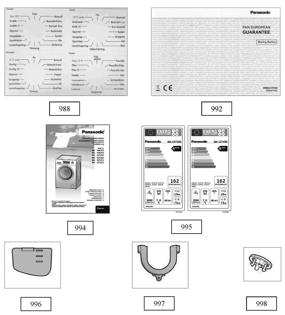
51 Accessories Replacement Parts List Ref. No. DESCRIPTION Pana No. Quantity Model Country /Language 988 PROGRAM LABEL AXW90PL NA-127VB5WNR NOR, SWE, DNK, FIN 1 NA-147VB5WNR NOR, SWE, DNK, FIN AXW90PL NA-127VB5WPL ENG, LTU, EST, LVA AXW90PL NA-147VB5WGN ROM, CRO, BUL, SVN AXW90PL NA-147VB5WGN POL, CZE, SVK, HUN AXW90PL NA-147VB5WGN NLD, FRA, TUR, SRB 988 PROGRAM LABEL GROUP AXW90PL NA-147VB5WGN 992 SERVICE LIST GUARANTEE AXW USER'S MANUEL AXW4F NA-127VB5WES SPAIN AXW4F NA-127VB5WES PORTUGAL AXW4F NA-127VB5WFR FRANCE AXW4F NA-127VB5WGB UK 1 NA-147VB5WGB UK AXW4F NA-127VB5WGN WIDE USAGE 1 NA-127VB5WTA ITALY AXW4F NA-127VB5WNR ENGLISH 1 NA-147VB5WNR ENGLISH AXW4F NA-127VB5WPL ENGLISH AXW4F NA-127VB5WPL POLAND AXW4F NA-147VB5WDE GERMANY AXW4F NA-147VB5WGN GERMANY/WIDE USAGE AXW4F NA-147VB5WGN WIDE USAGE AXW4F NA-147VB5WGN HOLLAND AXW4F NA-147VB5WGN CZECH AXW4F NA-147VB5WGN HUNGARY AXW4F NA-147VB5WNR NORWAY AXW4F NA-147VB5WNR SWEDEN AXW4F NA-147VB5WNR DENMARK AXW4F NA-147VB5WNR FINLAND 995 ENERGY LABEL AXW90EL NA-127VB5 AXW90EL NA-147VB5 996 LIQUID DETERGENT LEVEL PLATE AXW90LD DRAIN HOSE COAT RACK AXW90HC TRANSPORT SCREW STOPPER AXW1TS
52 Packaging Group Parts Exploded View Packaging Group Accessories 52
53 Package Group Replacement Parts List Ref. No. DESCRIPTION Pana No. Quantity Model Country /Language 900 BTM STYRF47-SIGMA PLUS AXWPV TOP CARTON AXWPV NA-127VB5 AXWPV NA-147VB5 902 REAR STYROFOAM (LEFT) AXWPV REAR STYROFOAM (RIGHT) AXWPV FRONT STYROFOAM (LEFT) AXWPV FRONT STYROFOAM (RIGHT) AXWPV CORNER CARDBOARD AXWPV TUB SUPPORT STYROFOAM AXWPV PORTHOLE SUPPORT STYROFOAM AXWPV PACKAGE CARTON AXWPV
TABLE OF CONTENTS. Drum Type Washing Machine
 Order No. VES1504003CE Drum Type Washing Machine Model No. NA-127VB6WGB Model No. NA-127VB6WFR Model No. NA-127VB6WES Model No. NA-127VB6WTA Model No. NA-127VB6WPL Model No. NA-127VB6WGN Model No. NA-127VB6WNR
V Series Slim SERVICE MANUAL
 V Series Slim SERVICE MANUAL 1 TABLE OF CONTENTS PAGE 1. Specifications 3 1.1. Product Specifications 3 1.2. Name Plate 3 2. Installation Instructions 4 2.1. Moving and Installing 4 2.2. Detergent Box
ALVA B SERVICE MANUAL
 ALVA B SERVICE MANUAL 1 TABLE OF CONTENTS PAGE 1. Specifications 3 1.1. Product Specifications 3 1.2. Name Plate 3 2. Installation Instructions 4 2.1. Moving and Installing 4 2.2. Detergent Box Group 5
FL PYTHON EXPLODED VIEW
 NO PART NAME QUANTITY 00 DETERJAN DRAWER COVER 0 CONTROL PANEL 02 PR.ADJ.KN GR 03 PROGRAMME ADJUSTMENT SHAFT 0 PROGRAM SELECTION KNOB INSERT PCB BOX 2 ELECTRONIC CARD GR. 9 LCD CARD GR 20 LCD CARD 22 FL
MIRANDA F2 EXPLODED VIEW
 NO PART NAME QUANTITY 400 DETERGENT DRAWER COVER 40 CONTROL PANEL 402 PR. ADJUSTMENT KNOB GR (470+47) 403 PROGRAMME ADJUSTMENT SHAFT 405 LIGHT GUIDE DUO 406 BUTTON&LIGHTGUIDE BOX 4 PCB BOX 42 ELECTRONIC
TITANIA F4 PYTHON EXPLODED VIEW
 400 DETERGENT DRAWER COVER 40 CONTROL PANEL 402 PR. ADJUSTMENT KNOB GR (470+47) 403 PROGRAMME ADJUSTMENT SHAFT 407 BUTTON-LIGHT GUIDE GROUP 405 LIGHT GUIDES 406 BUTTON LIGHT GUIDE BOX 45 BUTTONS 4 PCB
Service Info for WM105V Washing Machines
 Service Info for WM105V Washing Machines May 2014 CONTROL PANEL PARTS 400 DETERGENT DRAWER COVER 1 401 CON.PAN.WITH SRGF 1 402 PROGRAM ADJ. KNOB 1 403 PROGRAMME ADJUSTMENT SHAFT 1 405 LIGHT GUIDE DUO 1
Service Info for WM126VS2 Washing Machines
 Service Info for WM126VS2 Washing Machines October 2018 Exploded View 1 - Control Panel Parts 400 DETERGENT DRAWER COVER 1 401 CON.PAN.WITH SRGF 1 402 PROGRAM ADJ. KNOB 1 403 PROGRAMME ADJUSTMENT SHAFT
Service Manual for WM126V2 Washing Machines
 Service Manual for WM126V2 Washing Machines October 2018 Exploded View 1 - Control Panel Parts 400 DETERGENT DRAWER COVER 1 401 CON.PAN.WITH SRGF 1 402 PROGRAM ADJ. KNOB 1 403 PROGRAMME ADJUSTMENT SHAFT
Service Manual F2 SERIES. S/M No. : Caution
 S/M No. : Service Manual F2 SERIES Caution : In this Manual, some parts can be changed for improving, their performance without notice in the parts list. So, if you need the latest parts information, please
WASHING MACHINE INSTRUCTION MANUAL
 WM105V WM105VB WM105VS WASHING MACHINE INSTRUCTION MANUAL Please read this instruction manual carefully before you use this product CONTENTS SECTION 1: BEFORE USE Safety warnings Recommendations SECTION
WASHING MACHINE INSTRUCTION MANUAL
 WM126V WM126VS WM 126VB WASHING MACHINE INSTRUCTION MANUAL Please read this instruction manual carefully before you use this product CONTENTS SECTION 1: BEFORE USE Safety warnings Recommendations SECTION
WASHING MACHINE READ THIS MANUAL CAREFULLY TO DIAGNOSE TROUBLE CORRECTLY BEFORE OFFERING SERVICE.
 website : http://www.lgeservice.com e-mail : http://lgeservice.com/techsup.html WASHING MACHINE SERVICE MANUAL CAUTION READ THIS MANUAL CAREFULLY TO DIAGSE TROUBLE CORRECTLY BEFORE OFFERING SERVICE. MODEL
SERVICE MANUAL WASHING MACHINE MODEL : WD-10120FD WD-12120(5)FD WD-14120(5)FD FWD-12120(5)FD FWD-14120(5)FD CAUTION
FD WD-14120(5)FD FWD-12120(5)FD FWD-14120(5)FD CAUTION") website : http://www.lgeservice.com e-mail : http://lgeservice.com/techsup.html WASHING MACHINE SERVICE MANUAL CAUTION READ THIS MANUAL CAREFULLY TO DIAGSE TROUBLE CORRECTLY BEFORE OFFERING SERVICE. MODEL
website : http://www.lgeservice.com e-mail : http://lgeservice.com/techsup.html WASHING MACHINE SERVICE MANUAL CAUTION READ THIS MANUAL CAREFULLY TO DIAGSE TROUBLE CORRECTLY BEFORE OFFERING SERVICE. MODEL
WASHING MACHINE READ THIS MANUAL CAREFULLY TO DIAGNOSE TROUBLE CORRECTLY BEFORE OFFERING SERVICE.
 website : http://www.lgeservice.com e-mail : http://lgeservice.com/techsup.html WASHING MACHINE SERVICE MANUAL CAUTION READ THIS MANUAL CAREFULLY TO DIAGSE TROUBLE CORRECTLY BEFORE OFFERING SERVICE. MODEL
SERVICE MANUAL WASHING MACHINE
 Website:http://www.LGEservice.com E-mail:http://www.LGEservice.com/techsup.html WASHING MACHINE SERVICE MANUAL! CAUTION READ THIS MANUAL CAREFULLY TO DIAGSE PROBLEMS CORRECTLY BEFORE SERVICING THE UNIT.
REPAIR PART DIAGRAMS. Pages: 1-6
 REPAIR PART DIAGRAMS PRODUCT: MODEL: WASHER AW NA The information included in this Ariston Spare Parts List may change without notice please see our web site www.usservicenet.com for updates, corrections
User manual. Washing Machine ZWP 581 ZWQ 5102 ZWQ 5103 ZWQ 5122
 EN User manual Washing Machine ZWP 58 ZWQ 502 ZWQ 503 ZWQ 522 Contents Safety information 2 Product description _ 3 How to run a wash cycle? 4 Daily use _ 5 Washing programmes 6 Care and cleaning 8 Safety
SERVICE MANUAL WASHING MACHINE FWD-12120(5)FD FWD-14120(5)FD FWD-16120(5)FD DWD-12120(5)FD DWD-14120(5)FD DWD-16120(5)FD
FD FWD-14120(5)FD FWD-16120(5)FD DWD-12120(5)FD DWD-14120(5)FD DWD-16120(5)FD") website : http://www.lgeservice.com e-mail : http://lgeservice.com/techsup.html WASHING MACHINE SERVICE MANUAL CAUTION READ THIS MANUAL CAREFULLY TO DIAGSE TROUBLE CORRECTLY BEFORE OFFERING SERVICE. MODEL
website : http://www.lgeservice.com e-mail : http://lgeservice.com/techsup.html WASHING MACHINE SERVICE MANUAL CAUTION READ THIS MANUAL CAREFULLY TO DIAGSE TROUBLE CORRECTLY BEFORE OFFERING SERVICE. MODEL
WASHING MACHINE SERVICE MANUAL CAUTION READ THIS MANUAL CAREFULLY TO DIAGNOSE PROBLEMS CORRECTLY BEFORE SERVICING THE UNIT.
 WASHING MACHINE SERVICE MANUAL CAUTION READ THIS MANUAL CAREFULLY TO DIAGSE PROBLEMS CORRECTLY BEFORE SERVICING THE UNIT. MODEL : WM2240C* Jul. 2010 PRINTED IN KOREA P/No. : MFL30599179 CONTENTS 1.SPECIFICATIONS...
User manual. Washing machine ZWQ 6120 ZWQ 6100
 EN User manual Washing machine ZWQ 6120 ZWQ 6100 Product description 1 1. The control panel 2. Lid handle 3. Adjustable levelling feet 2 3 The control panel 1 2 3 4 5 6 1. Programme selector 2. Pushbuttons
WHIRLPOOL AUSTRALASIA CONSUMER SERVICES
 October 2001 WHIRLPOOL AUSTRALASIA CONSUMER SERVICES SERVICE MANUAL FRONT LOAD WASHING MACHINE Version 8570 814 53100 Copyright 2001 Whirlpool (Australia) Pty. Limited All rights strictly reserved. Reproduction
GB User manual. Washing machine ZWQ 5130
 GB User manual 2 Washing machine ZWQ 5100 ZWQ 5101 ZWQ 5130 Product description 1 1. The control panel 2. Lid handle 3. Adjustable levelling feet 2 3 The control panel 1 2 3 4 5 6 1. Programme selector
TOP AND CABINET PARTS
 TOP AND CABINET PARTS AUTOMATIC WASHER 3 10 Printed in U.S.A. (drd) (psw) 1 Part No. Rev. A TOP AND CABINET PARTS 1 Literature Parts W10157503 Use & Care Guide W10177425 Tech Sheet W10157501 Energy Guide
washing machine contents
 washing machine contents WARNINGS SPECIFICATIONS INSTALLATION AND ASSEMBLY USING THE APPLIANCE. PRACTICAL TIPS MAINTENANCE AND CLEANING SAFETY AND TROUBLESHOOTING ENVIRONMENTAL WARNINGS 4 5 6 10 20 22
Dear Customer, We wish that this product, manufactured at modern facilities with total quality notions, will deliver you the best performance.
 Dear Customer, We wish that this product, manufactured at modern facilities with total quality notions, will deliver you the best performance. In order to guarantee this, please read this instruction manual
User manual. Washing machine ZWQ 590 SO ZWQ 585 SO ZWQ 580 SO ZWQ 575 SO ZWQ 570 SO
 EN User manual Washing machine ZWQ 590 SO ZWQ 585 SO ZWQ 580 SO ZWQ 575 SO ZWQ 570 SO Product description 1 The control panel 2 Lid handle 3 Filter access cover 4 Adjustable levelling feet Control panel
It is essential to read this manual carefully before it is installed and used for the first time. EFL6KWH
 It is essential to read this manual carefully before it is installed and used for the first time. EFL6KWH This washing machine conforms to current safety requirements. Inappropriate use can, however, lead
SERVICE MANUAL WASHING MACHINE MODEL : WD(M)-1018(0~9)S WD(M)-8018(0~9)N CAUTION
-1018(0~9)S WD(M)-8018(0~9)N CAUTION") website : http://www.lgeservice.com e-mail : http://lgeservice.com/techsup.html WASHING MACHINE SERVICE MANUAL CAUTION READ THIS MANUAL CAREFULLY TO DIAGSE TROUBLE CORRECTLY BEFORE OFFERING SERVICE. MODEL
website : http://www.lgeservice.com e-mail : http://lgeservice.com/techsup.html WASHING MACHINE SERVICE MANUAL CAUTION READ THIS MANUAL CAREFULLY TO DIAGSE TROUBLE CORRECTLY BEFORE OFFERING SERVICE. MODEL
Service Manual Washing machine Frontloader
 SERVICE Whirlpool Europe Customer Services AWM 293/3 Service Manual Washing machine Frontloader AWM 293/3 Model AWM 293/3 Version 8570 293 53310 Page Technical data 2-3 Spare part list 4 Exploded view
WASHING MACHINE USER MANUAL WM1201WH WM1201SL
 WASHING MACHINE USER MANUAL WM1201WH WM1201SL THE CONTENTS SECTION 1:BEFORE USE Safety warnings Recommendations SECTION 2:INSTALLATION Removal of transportation screws Foot adjustment Electrical connection
REPAIR PART DIAGRAMS PRODUCT: WASHER MODEL: AW 120
 REPAIR PART DIAGRAMS PRODUCT: WASHER MODE: AW 0 The information included in this Ariston Spare Parts ist may change without notice please see our web site www.usservicenet.com for updates, corrections
SERVICE MANUAL WASHING MACHINE MODEL: WM3431H*/WM3434H* WD-14312RD/WD-14316RD CAUTION
 Website: http://www.lgeservice.com [For U.S.A] www.lg.ca [For CANADA] E-mail: http://www.lgeservice.com/techsup.html WASHING MACHINE SERVICE MANUAL! CAUTION READ THIS MANUAL CAREFULLY TO DIAGSE PROBLEMS
7 FAULT DIAGNOSTICS COMPONENTS Appliance stability... 26
 REPAIR INSTTRUCTTI I IONS F10-C 1 SAFETY... 2 4.5 NTC... 13 1.1 Safety instructions... 2 1.3 ESD... 3 2 INSTALLATION... 5 2.1 Aligning the appliance... 5 2.2 Hose and electric cable lengths... 5 2.3 Water
GETTING STARTED? EASY.
 User Manual GETTING STARTED? EASY. ZWF 71440W EN User Manual Washing Machine SAFETY INFORMATION Before the installation and use of the appliance, carefully read the supplied instructions. The manufacturer
SERVICE MANUAL WASHING MACHINE MODEL: WM2496H*M CAUTION. Website: http: //www.lgeservice.com http: //www.lgeservice.com/techsup.
 Website: http: //www.lgeservice.com E-mail: http: //www.lgeservice.com/techsup.html WASHING MACHINE SERVICE MANUAL! CAUTION READ THIS MANUAL CAREFULLY TO DIAGSE PROEMS CORRECTLY BEFORE SERVICING THE UNIT.
SERVICE MANUAL WASHING MACHINE MODEL : WD(M)-80150FB CAUTION. website :
-80150FB CAUTION. website :") website : http://www.lgeservice.com e-mail : http://lgeservice.com/techsup.html WASHING MACHINE SERVICE MANUAL CAUTION READ THIS MANUAL CAREFULLY TO DIAGSE TROUBLE CORRECTLY BEFORE OFFERING SERVICE. MODEL
website : http://www.lgeservice.com e-mail : http://lgeservice.com/techsup.html WASHING MACHINE SERVICE MANUAL CAUTION READ THIS MANUAL CAREFULLY TO DIAGSE TROUBLE CORRECTLY BEFORE OFFERING SERVICE. MODEL
SERVICE MANUAL WASHING MACHINE MODEL: WM2277H*/WM2077CW/ WM2177H*/WM2677H*M CAUTION
 Website: http: //www.lgeservice.com E-mail: http: //www.lgeservice.com/techsup.html WASHING MACHINE SERVICE MANUAL! CAUTION READ THIS MANUAL CAREFULLY TO DIAGSE PROBLEMS CORRECTLY BEFORE SERVICING THE
Fora Failure Algorithms
 FORA FUNCTIONAL TEST MODE : NOTE: To prevent any misunderstanding, entering the functional test mode ends the running program and erases any failure code stored in the memory. So the service firstly must
WASHING MACHINE SERVICE MANUAL
 website : http://www.lgeservice.com e-mail : http://lgeservice.com/techsup.html WASHING MACHINE SERVICE MANUAL CAUTION READ THIS MANUAL CAREFULLY TO DIAGSE TROUBLE CORRECTLY BEFORE OFFERING SERVICE. MODEL
Black 8KG 1400 Spin Speed Inverter Direct Drive Washing Machine Instruction Manual
 Black 8KG 1400 Spin Speed Inverter Direct Drive Washing Machine Instruction Manual Model number: RHWM81400DIDB Opening times: Monday - Friday 8am 6pm & Saturday 9am 1pm or visit us at Contents Safety Instructions
WASHER EXTRACTOR M XQG60-A508K
 WASHER EXTRACTOR 4160980M XQG60-A508K It is essential to read this manual carefully before it is installed and used for the first time. 9 12 14 15 Correct use Read and understand thoroughly these safety
ensure Ensure Single inlet Dual inlet - only and cold
 X08060026A NOTE The manufacturer reserves the right for any modifications on the product which might be deemed necessary or useful without informing about it in this IFU. Thank you for choosing a Hisense
TOP AND CABINET PARTS For Models: GHW9200LW0, GHW9200LQ0 (White/Grey) (White/Blue)
 (White/Blue)") TOP AND CABINET PARTS AUTOMATIC WASHER 11 02 Printed In U.S.A. (awm) 1 Part No. 8181891 Rev. A TOP AND CABINET PARTS 1 Literature Parts LIT8181894 Use & Care Guide LIT8181790 Tech Sheet LIT8181895 Energy
TOP AND CABINET PARTS AUTOMATIC WASHER 11 02 Printed In U.S.A. (awm) 1 Part No. 8181891 Rev. A TOP AND CABINET PARTS 1 Literature Parts LIT8181894 Use & Care Guide LIT8181790 Tech Sheet LIT8181895 Energy
10kg Washing Machine
 Instruction Manual 10kg Washing Machine L1014WM17 L1014WM17_IB.indd 1 26/07/2017 11:31 L1014WM17_IB.indd 2 26/07/2017 11:31 Contents Safety Warnings... 4 Unpacking... 6 Removing the Transit Bolts... 7
Parts Manual Front Loading Washing Machine
 Parts Manual Front Loading Washing Machine Model: WH60F60WV1 FP AA Product Code: 2 Brand Fisher & Paykel Voltage 220-240V 50Hz Model WH60F60WV1 FP AA Product Code PRODUCT - DECEMBER 2010 Fisher & Paykel
TECHNICAL INFORMATION Touchtronic Clothes Dryers
 TECHNICAL INFORMATION Touchtronic Clothes Dryers Includes: T1302, T1303, T1322, T1329ci T1403 & T1405 2004 Miele This page intentionally left blank. Table of Contents GENERAL INFORMATION A. Warning and
REPAIR PART DIAGRAMS. Pages: 1-7
 REPAIR PART DIAGRAMS PRODUCT: MODE: WASHER/DRYER COMBO AWD A The information included in this Ariston Spare Parts ist may change without notice please see our web site www.usservicenet.com for updates,
TABLE OF CONTENTS REFRIGERATOR-FREEZER. Model No. NR-BN34FX1 Model No. NR-BN34FW1
 Order Number GORR1405001CE REFRIGERATOR-FREEZER Model No. NR-BN34FX1 Model No. NR-BN34FW1 Product-Color X:Stainless W:White Destination E(Europe Continental) B(U.K.) TABLE OF CONTENTS PAGE 1 Safety Precautions-----------------------------------------------
GETTING STARTED? EASY.
 User Manual GETTING STARTED? EASY. ZWF 81240W ZWF 81440W EN User Manual Washing Machine SAFETY INFORMATION Before the installation and use of the appliance, carefully read the supplied instructions. The
TOP AND CABINET PARTS
 TOP AND CABINET PARTS AUTOMATIC WASHER 7 06 Printed in U.S.A. (drd) 1 Part No. TOP AND CABINET PARTS 1 Literature Parts 8182751 Use & Care Guide 8182142 DVD Instruction 8182658 Quick Start Guide 8182208
Test Program - Coding Instruction B/S/H/
 Contents Page 1. programs 1-4 2. Final factory test 4 3. Error search 4-5 4. List of error numbers 6-8 5. Variant coding 9-11 1. programs Activate test mode: Indication - Close the door - Set program selector
Granule Gastro/Combi
 Granule Gastro/Combi Spare parts list Granule Gastro serial # 710010- Granule Combi serial # 810010- Art. No. EN 21111-2010-03. GRANULDISK AB retains the right to make technical changes to the products.
WASHING MACHINE READ THIS MANUAL CAREFULLY TO DIAGNOSE TROUBLE CORRECTLY BEFORE OFFERING SERVICE.
 website : http://www.lgeservice.com e-mail : http://lgeservice.com/techsup.html WASHING MACHINE SERVICE MANUAL CAUTION READ THIS MANUAL CAREFULLY TO DIAGSE TROUBLE CORRECTLY BEFORE OFFERING SERVICE. MODEL
Unpacking and removing shipping bolts. Connecting the drain line Leveling the washer Connecting to the power supply
 11 INSTALLATION Installation Overview Choosing the proper location Unpacking and removing shipping bolts Connecting the water line Connecting the drain line Leveling the washer Connecting to the power
DISHWASHER SERVICE MANUAL
 DISHWASHER SERVICE MANUAL NOTE BEFORE SERVICING THE UNIT, PLEASE READ THIS MANUAL CAREFULLY FOR SAFETY AND CORRECT SERVICES. MODEL : LD-2040WH/LD-2040SH/LD-2040MH CONTENTS 1. CAUTION... 4 2. SPECIFICATIONS...
Instruction manual. Washing Machine WMDF612W
 Instruction manual Washing Machine WMDF612W You ll soon be enjoying your new washing machine. It all begins here, with your instructions. Don t worry, there s nothing too technical coming up. Just simple,
User manual. Washing Machine ZWG 6148K
 EN User manual Washing Machine ZWG 6148K Contents Safety information 2 Safety instructions 3 Environment concerns 4 Product description _ 5 Control panel _ 6 Washing programmes 6 Consumption values _ 7
SERVICE MANUAL WASHING MACHINE MODEL: WM2688H*M CAUTION. Website: http: // http: //
 Website: http: //www.lgeservice.com E-mail: http: //www.lgeservice.com/techsup.html WASHING MACHINE SERVICE MANUAL! CAUTION READ THIS MANUAL CAREFULLY TO DIAGSE PROEMS CORRECTLY BEFORE SERVICING THE UNIT.
AUTOMATIC WASHER HORIZONTAL AXIS. Product Type
 REPAIR PARTS LIST Model No.(s) 110.47761800 AUTOMATIC WASHER HORIZONTAL AXIS In U.S.A., To Call Toll Free For Parts: 1 800 366 PART (1 800 366 7278) For Service: 1 800 4 MY HOME (1 800 469 4663) In Canada,
Service Manual. Note: Before service the unit, please read this manual first. Contact with your service center if meet problem
 Kleenmaid Dryer Model:KCDV60 Service Manual Note: Before service the unit, please read this manual first. Contact with your service center if meet problem Contents 1 PRECAUTION....3 1.1 Safety Precautions
Instruction Manual. 6kg Washing Machine L612WM15/L612WMS15. L612WM15/S15_IB.indd 1 10/08/ :00
 Instruction Manual 6kg Washing Machine L612WM15/L612WMS15 L612WM15/S15_IB.indd 1 10/08/2015 13:00 Contents Safety Warnings... 3 Unpacking... 5 Moving and Installing... 6 Removing the Transit Bolts... 6
Washing Machine OWNER S MANUAL TRWTL-70. Before using your washing machine, please read this manual carefully and keep it for future reference.
 Before using your washing machine, please read this manual carefully and keep it for future reference. Washing Machine OWNER S MANUAL TRWTL-70 Read This Manual Inside you will find many helpful hints on
G6FLWW17 6KG WASHING MACHINE
 G6FLWW17 6KG WASHING MACHINE G6FLWW17_IB_170919_grace.indd 1 Contents Guide to the Appliance 2 Caring for the Environment 3 Safety Information and Warnings 4 Items in the Box 6 Getting Started 7 Basic
en-us Use and Care Manual, Installation Instructions Washer WAT28400UC
 en-us Use and Care Manual, Installation Instructions Washer WAT28400UC Under counter (Less Desirable) If front of the appliance is covered ventilation openings must be installed. E & F are minimum area
! WARNING To avoid risk of electrical shock, personal injury or death; disconnect power to washer before servicing, unless testing requires power.
 24 Front Load Washer Technical Information MAH2400A* Due to possibility of personal injury or property damage, always contact an authorized technician for servicing or repair of this unit. Refer to Service
Contents Contents... 2 Safety Warning... 3 Unpacking... 6 Installation... 7 Installing Your Washing Machine... 7 Moving and Installing...
 Contents Contents...2 Safety Warning...3 Unpacking...6 Installation...7 Installing Your Washing Machine...7 Choosing the Right Location for Your Washing Machine... 7 Moving and Installing...8 Removing
User manual. Washing Machine ZWG K
 EN User manual Washing Machine ZWG 71202 K Contents Safety information 2 Safety instructions 3 Environment concerns 4 Product description _ 5 Control panel _ 6 Washing programmes 7 Consumption values _
Model: Sunrise WFS1071AW/WFS1072AW /WFS1273AW/WFS1274AW/WFS1276AW/WFS1273BW/WFS10 71BW/WFS1071BD/WFS1273BD/WFS1276BD
 Service Manual Model: Sunrise WFS1071AW/WFS1072AW /WFS1273AW/WFS1274AW/WFS1276AW/WFS1273BW/WFS10 71BW/WFS1071BD/WFS1273BD/WFS1276BD Contents 1 Technical data ------------------------------2 2 Parts list
EWM 1000 COMPONENT FUNCTIONALITY
 EWM 1000 COMPONENT FUNCTIONALITY TSE-N / A.S. 1 EWM 1000 Electronic control TSE-N / A.S. 2 EWM 1000 Electronic control heating relay motor triac with heat sink microprocessor mains supply programme selector
MIX Boiler & Font Range Service Manual
 MIX Boiler & Font Range Service Manual 1000870# 1000871# 1000875# 1000880# 1000887# 1000878 1000879 2300268 www.marcobeveragesystems.com Ireland Tel: +353 (1) 295 2674 UK Tel: +44 (0207) 2744577 Service
SERVICE MANUAL WASHING MACHINE MODEL: WM2233H* / WM2233H*/01 CAUTION
 Website: http: //www.lgeservice.com E-mail: http: //www.lgeservice.com/techsup.html WASHING MACHINE SERVICE MANUAL! CAUTION READ THIS MANUAL CAREFULLY TO DIAGSE PROEMS CORRECTLY BEFORE SERVICING THE UNIT.
User Manual Washing Machine L61470BI
 EN User Manual Washing Machine L61470BI 2 www.aeg.com CONTENTS 1. SAFETY INFORMATION...3 2. SAFETY INSTRUCTIONS... 4 3. PRODUCT DESCRIPTION... 6 4. CONTROL PANEL...7 5. PROGRAMMES... 9 6. CONSUMPTION VALUES...11
 CONTENTS 1. Specifications... 2. Features and Technical Explanation... 2-1. Featurs... 2-2. Neuro fuzzy Washing time optimization... 2-3. Water level Contorl... 2-4. Door Contorl... 2-5. The door can cont
4 Selecting a Program and Operating Your Machine
 4 Selecting a Program and Operating Your Machine Control panel Figure 1 1 2 3 4 5 6 7 8 1 - Spin Speed Adjustment button 2 - Display 3 - Temperature Adjustment button 4 - Programme Selection knob 5 - On
CONTENTS QUICK REFERENCE GUIDE PROGRAMME CHART
 1 CONTENTS Please read instruction for use QUICK REFERENCE GUIDE PREPARING THE LAUNDRY SELECTING A PROGRAMME AND OPTIONS STARTING AND COMPLETING A PROGRAMME CHANGING A PROGRAMME PROGRAMME CHART INTERRUPTING
SERVICE MANUAL DISHWASHERS DIVA ACCESSIBILITY DISHWASHERS
 SERVICE MANUAL DISHWASHERS DIVA ELECTROLUX HOME PRODUCTS S.p.A. Publication no. Spares Operations Italy Corso Lino Zanussi,30 I - 33080 PORCIA /PN (ITALY) 599 38 70-09 Fax +39 0434 394096 EN DISHWASHERS
MODEL MC-UL592 MC-UL594 POWER SOURCE. 230V - 240V ~ 50 Hz MAX INPUT 1400 W 1500 W NOMINAL INPUT DIMENSIONS (W x L x H)
") Order Number: PMMA091040CE Vacuum Cleaner MC-UL592/MC-UL594 SPECIFICATION MODEL MC-UL592 MC-UL594 POWER SOURCE 230V - 240V ~ 50 Hz MAX INPUT 1400 W 1500 W NOMINAL INPUT DIMENSIONS (W x L x H) 1200-1300
Order Number: PMMA091040CE Vacuum Cleaner MC-UL592/MC-UL594 SPECIFICATION MODEL MC-UL592 MC-UL594 POWER SOURCE 230V - 240V ~ 50 Hz MAX INPUT 1400 W 1500 W NOMINAL INPUT DIMENSIONS (W x L x H) 1200-1300
FULL ELECTRONIC WASHING MACHINE USER MANUAL
 FULL ELECTRONIC WASHING MACHINE USER MANUAL THE CONTENTS SECTION 1:BEFORE USING Safety warnings Recommendations SECTION 2:INSTALLATION Removal of transportation screws Adjustment of feet Electrical connection
SERVICE MANUAL WASHING. Washer-dryers HEC-RIM HEC-ARCHED. Structural characteristics, electrical components, accessibility
 SERVICE MANUAL WASHING HEC-RIM HEC-ARCHED Washer-dryers ELECTROLUX HOME PRODUCTS ITALY S.p.A. Spares Operations Italy Corso Lino Zanussi,30 Publication number I - 33080 PORCIA /PN (ITALY) 599 70 40-15
Washing Machine WF 7141 N
 Washing Machine WF 7141 N 1 Warnings General Safety Never place your machine on a carpet covered floor. Otherwise, lack of airflow from below of your machine may cause electrical parts to overheat. This
SERVICE MANUAL WASHING. ENV06 AEG Styling SERIES 6 / 7. Washing machines & Washer-dryers. with electronic control system.
 SERVICE MANUAL WASHING ELECTROLUX HOME PRODUCTS ITALY S.p.A. Spares Operations Italy Publication no. Corso Lino Zanussi, 30 I - 33080 PORCIA /PN 599 70 39-88 Fax +39 0434 394096 Edition: 2007-08-11 EN
User Manual. Washing Machine ZWF 91483WH ZWF 91483WR
 EN User Manual Washing Machine ZWF 91483WH ZWF 91483WR Contents Safety information 2 Safety instructions 3 Product description 4 Control panel 5 Programme Chart 6 Consumption values 7 Options 8 Settings
6KG 1200 Spin Speed Washing Machine. Instruction Manual
 6KG 1200 Spin Speed Washing Machine Instruction Manual Model number: RHWM61200B Opening times: Monday - Friday 8am 6pm & Saturday 9am 1pm or visit us at www.productcareuk.com Contents Safety Instructions
INSTRUCTION MANUAL 6KG WASHING MACHINE C610WM16. C610WM16_IB.indd 1 29/01/ :27
 INSTRUCTION MANUAL 6KG WASHING MACHINE C610WM16 C610WM16_IB.indd 1 29/01/2016 12:27 Contents Unpacking... 5 Installing Your Washing Machine... 6 Choosing the Right Location for Your Washing Machine...
FAVORIT DISHWASHER USER MANUAL
 FAVORIT 77000 DISHWASHER USER MANUAL 2 CONTENTS 4 SAFETY INFORMATION 6 PRODUCT DESCRIPTION 7 CONTROL PANEL 8 PROGRAMMES 10 OPTIONS 11 BEFORE FIRST USE 14 DAILY USE 17 CARE AND CLEANING 18 TROUBLESHOOTING
WE 170 P. EN User Manual Washing Machine. CAUTION: Read the instructions before using the appliance. Original Instructions.
 WE 170 P EN User Manual Washing Machine CAUTION: Read the instructions before using the appliance. Original Instructions. 2 www.electrolux.com CONTENTS 1. SAFETY INFORMATION... 2 2. PRODUCT DESCRIPTION...
Nilfisk Inc Winnetka Avenue North Minneapolis, MN REV.03( ) VF80189
 VF80189") Nilfisk Inc. 9435 Winnetka Avenue North Minneapolis, MN 55445 www.usviper.com REV.03(05-) VF8089 SAFETY PRECAUTIONS This machine is intended for commercial use. It is constructed for use in an indoor
Nilfisk Inc. 9435 Winnetka Avenue North Minneapolis, MN 55445 www.usviper.com REV.03(05-) VF8089 SAFETY PRECAUTIONS This machine is intended for commercial use. It is constructed for use in an indoor
Instruction / Installation Manual. 7KG Washing Machine L714WM17
 Instruction / Installation Manual 7KG Washing Machine L714WM17 Contents Safety Warning...3 Unpacking...6 Installation...7 Installing Your Washing Machine...7 Choosing the Right Location for Your Washing
Operating & Installation Instructions Fully Automatic Washing Machine (Domestic use)
") Operating & Installation Instructions Fully Automatic Washing Machine (Domestic use) Model No. NA-F00A NA-F90A NA-F85A Contents Safety Precautions Part Names 3 Operation Panel 4 Variety of Programs 5 Detergent
Operating & Installation Instructions Fully Automatic Washing Machine (Domestic use) Model No. NA-F00A NA-F90A NA-F85A Contents Safety Precautions Part Names 3 Operation Panel 4 Variety of Programs 5 Detergent
Operator s Manual READY RACK EXTRACTOR. Installation/Operation/Maintenance/Parts DIMENSIONS OF THE WASHER: HEIGHT (AT BACK): 42
: 42") READY RACK EXTRACTOR DIMENSIONS OF THE WASHER: HEIGHT (AT BACK): 42 HEIGHT (W/ LID RAISED): 56 WIDTH: 27 DEPTH: 26 DEPTH (W/ REAR HOSE): 30 WEIGHT: 190 lbs. SHIP WEIGHT: 255 lbs. Operator s Manual Installation/Operation/Maintenance/Parts
READY RACK EXTRACTOR DIMENSIONS OF THE WASHER: HEIGHT (AT BACK): 42 HEIGHT (W/ LID RAISED): 56 WIDTH: 27 DEPTH: 26 DEPTH (W/ REAR HOSE): 30 WEIGHT: 190 lbs. SHIP WEIGHT: 255 lbs. Operator s Manual Installation/Operation/Maintenance/Parts
Washer-Extractor. Parts. Refer to Page 4 for Model Identification. Part No. D1662
 Washer-Extractor Refer to Page 4 for Model Identification Parts Part No. D1662 www.alliancelaundry.com April 2015 PARTS ORDERING INFORMATION If literature or replacement parts are required, contact the
CABINET AND COIN BOX PARTS For Model: MFS18PDFTS (Stainless)
") CABINET AND COIN BOX PARTS COMMERCIAL INDUSTRIAL WASHER 12 11 Litho In U.S.A. (CMS)(bay) 1 Part No. Rev. B CABINET AND COIN BOX PARTS 1 23004302 Control Panel Coin 2 W10357106 Front To Back Reinforcement
CABINET AND COIN BOX PARTS COMMERCIAL INDUSTRIAL WASHER 12 11 Litho In U.S.A. (CMS)(bay) 1 Part No. Rev. B CABINET AND COIN BOX PARTS 1 23004302 Control Panel Coin 2 W10357106 Front To Back Reinforcement
TOP AND CABINET PARTS For Model: WFW9151YW00 (White)
") TOP AND CABINET PARTS AUTOMATIC WASHER 7 11 Printed in U.S.A. (drd) (psw) 1 Part No. Rev. A TOP AND CABINET PARTS 1 Literature Parts W10408696 Installation Instructions W10432633 Use & Care Guide W10385295
TOP AND CABINET PARTS AUTOMATIC WASHER 7 11 Printed in U.S.A. (drd) (psw) 1 Part No. Rev. A TOP AND CABINET PARTS 1 Literature Parts W10408696 Installation Instructions W10432633 Use & Care Guide W10385295
Removing shipping locks
 y Safety instructions Scope of delivery Moisture in the drum is due to end inspection. Removing shipping locks Water connection l The washing machine is heavy - lift with caution. Frozen hoses can tear/burst.
XR510W 5KG 1000RPM WASHING MACHINE XR612W 6KG 1200RPM WASHING MACHINE. Instruction Manual
 XR510W 5KG 1000RPM WASHING MACHINE XR612W 6KG 1200RPM WASHING MACHINE Instruction Manual Serial number: Please read these instructions carefully before use and retain for future reference. Before switching
Spare parts list. Household washing machines PNC ELC Brand Model Market Electrolux EWF10841 TH. Washing machines, front-loaded
 Spare parts list Household washing machines 2520 PNC ELC Brand Model Market 914900303 00 Electrolux EWF10841 TH Washing machines, front-loaded Electrolux Publication-No. 599742292 2011/04/28 THR SPARE
Ensure. Single inlet Dual inlet -
 W10677398B NOTE The manufacturer reserves the right for any modifications on the product which might be deemed necessary or useful without informing about it in this IFU. Thank you for choosing a Hisense
WASHING MACHINE INSTRUCTION MANUAL
 WASHING MACHINE INSTRUCTION MANUAL Model num ber: HWM51000/HWM51000SW Please read these instructions carefully and keep them for future reference For Customer Services, Spare parts & Warranty Information
B/S/H/ Error codes and service programmes PW
 1 ERROR CODES AND APPLIANCE MESSAGES...2 1.1 Error codes... 2 OPEN... 2 E01... 2 E02... 2 E04... 2 E05... 2 E06... 2 E10... 3 E11... 3 E12... 3 E13... 3 E14... 4 E16... 4 E17... 4 E20... 4 E25... 4 E26...