E25 CONVECTION OVEN E25MS CONVECTION OVEN SERVICE MANUAL
|
|
|
- Jonah Bryant
- 5 years ago
- Views:
Transcription


1 E25 CONVECTION OVEN E25MS CONVECTION OVEN SERVICE MANUAL E25 Convection Oven --
2 WARNING: ALL INSTALLATION AND SERVICE REPAIR WORK MUST BE CARRIED OUT BY QUALIFIED PERSONS ONLY. E25 Convection Oven -2-
3 CONTENTS This manual is designed to take a more in depth look at the E25 convection oven for the purpose of making the unit more understandable to service people. There are settings explained in this manual that should never require to be adjusted, but for completeness and those special cases where these settings are required to change, this manual gives a full explanation as to how, and what effects will result. SECTION PAGE NO.. SPECIFICATIONS INSTALLATION OPERATION Description of Controls E Description of Controls E25B 3.3 Explanation of Control System 4. MAINTENANCE Cleaning 4.2 Routine Procedures 5. TROUBLE SHOOTING GUIDE SERVICE PROCEDURES Fault Diagnosis 6.2 Access 6.3 Replacement 6.4 Adjustment / Calibration 7. ELECTRICAL SCHEMATICS E E25B 8. ELECTRICAL WIRING DIAGRAMS E25 ( V) 8.2 E25 (0V) 8.3 E25B 9. SPARE PARTS IMPORTANT: MAKING ALTERATIONS MAY VOID WARRANTIES AND APPROVALS. E25 Convection Oven -3-
4 0. ACCESSORIES / OPTIONS PARTS DIAGRAM Main Assembly - E25.2 Main Assembly - E25B.3. Control Panel Assembly - E Control Panel Assembly - E25B.4. Control Panel Assembly - E25MS.4.2 Control Panel Assembly - E25BMS.5 Door Assembly - E25MS 2. SERVICE CONTACTS APPENDIX A. DOUBLE STACKING KIT E25 Convection Oven -4-
5 . SPECIFICATIONS MODEL: E25 / E25B 720 (28.4) 600 (23.6) (6.9) E E (.9) (24.6) 45 (.75) (4.9) (4.4) (5.5) FRONT SIDE E PLAN LEGEND - Electrical connection entry point Dimensions shown in millimetres. Dimensions in inches shown in brackets. E25 Convection Oven -5-
6 LOCATION To ensure correct ventilation for the motor and controls the following minimum installation clearances are to be adhered to: Top 200mm / 8 Rear 25mm / Left-hand side 25mm / Right-hand side 25mm / OVEN INTERNAL DIMENSIONS Width 470 mm / 8.5 Height 254 mm / 0.0 Depth 420 mm / 6.5 Oven Volume 0.05 m³ /.75 ft³ OVEN RACK SIZE Width 460 mm / 8 Depth: 370 mm / 4.5 ELECTRICAL SUPPLY SPECIFICATION OPTIONS E V ac, 60Hz, 20V V ac, 50/60Hz, 8.5A, 240V E25B 00-20V ac, 60Hz, 7.A, ELECTRICAL PLUG SPECIFICATION REQUIREMENTS E25 Australia 3-pin 250V 0A, AS/NZ 32 Canada 3-pin 20V 5A, NEMA 6-5 New Zealand 3-pin 250V 0A, AS/NZ 32 United Kingdom 3-pin 250V 3A fused, BS 363A United States 3-pin 20V 5A, NEMA 6-5 Other Countries 3-pin 250V 0A minimum, type to meet country standards E25B Canada 3-pin 20V 20A, NEMA 6-20 United States 3-pin 20V 20A, NEMA 6-20 E25 Convection Oven -6-

7 2. INSTALLATION WARNING: THIS APPLIANCE MUST BE GROUNDED. WARNING: ALL INSTALLATION AND SERVICE REPAIR WORK MUST BE CARRIED OUT BY QUALIFIED PERSONS ONLY. It is most important that the oven is installed correctly and that the operation is correct before use. Installation shall comply with local electrical, health and safety requirements. BEFORE USE Operate the oven for about hour at 200 C (400 F) to remove any fumes or odours which may be present. BEFORE CONNECTION TO POWER SUPPLY Unpack and check unit for damage and report any damage to the carrier and dealer. Report any deficiencies to your dealer. Check that the available power supply is correct to that shown on the rating plate located on the righthand side panel. E V ac, 60Hz, 20V V ac, 50/60Hz, 8.5A, 240V E25B 00-20V ac, 60Hz, 7.A, LOCATION To ensure correct ventilation for the motor, and controls the following minimum installation clearances are to be adhered to: Top 200mm / 8 Rear 25mm / Left-hand side 25mm / Right-hand side 25mm / ELECTRICAL CONNECTION E25 convection ovens are supplied with pre-fitted cords. Ensure unit is fitted with the correct cord and plug for the installation. Refer specifications section. Should changing of the cord be necessary, gain access to the electrical connection terminal block, grounding lug, and strain relief by removing the back panel (four screws). L L2 Ground Phase Neutral RED BROWN BLACK BLACK BLUE WHITE Figure 2. GREEN GREEN/YELLOW WARNING: THIS APPLIANCE MUST BE GROUNDED / EARTHED RATING PLATE LOCATION The rating plate for the E25 convection oven is located at the bottom left corner of the RH side panel. IMPORTANT: THE OVEN VENT LOCATED ON THE CABINET TOP MUST NEVER BE OBSTRUCTED. Position the oven in its allocated working position. Use a spirit level to ensure the oven is level from side to side and front to back. (If this is not carried out, uneven cooking could occur). The feet used with bench mounting or provided with stands are adjustable and will require adjusting in levelling the unit. It should be positioned so the operating panel and oven shelves are easily reachable for loading and unloading. Figure 2.2 Rating Plate E25 Convection Oven -7-
. 2. THERMOSTAT Temperature range 50-250 C (20-480 F).")
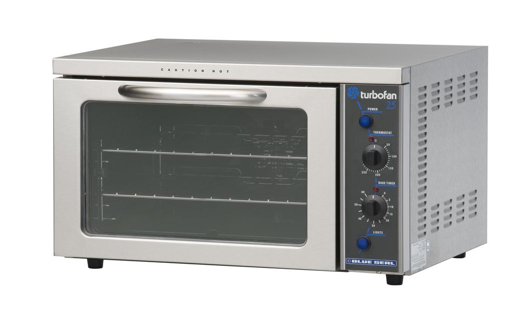
8 3. OPERATION NOTE: A full user s operation manual is supplied with the product and can be used for further referencing of installation, operation and service. 3. DESCRIPTION OF CONTROLS - E25. POWER Depress to switch power on or off (switch illuminates when power is on). 2. THERMOSTAT Temperature range C ( F). Indicator illuminates when elements are cycling ON to maintain set temperature. 3. BAKE TIMER Hour bake timer. (Indicator illuminates when time up (0) reached, and buzzer sounds) LIGHT SWITCH Push switch to activate light. (Oven light illuminates while button depressed). 3 4 E25 Convection Oven -8-
 - The BROIL indicator will illuminate indicating that the BROIL function has been set.")
9 3.2 DESCRIPTION OF CONTROLS - E25B. POWER Depress to switch power on or off (switch illuminates when power is on) THERMOSTAT Temperature range C ( F). (Indicator illuminates when elements are cycling ON to maintain set temperature. BROIL POSITION (E25B Only) - The BROIL indicator will illuminate indicating that the BROIL function has been set. The HEATING indicator will also illuminate whenever the elements are on. 3. BAKE TIMER Hour bake timer. (Indicator illuminates when time up (0) reached, and buzzer sounds). 4. LIGHT SWITCH Push switch to activate light. (Oven light illuminates while button depressed). 3 4 E25 Convection Oven -9-
10 3.3 EXPLANATION OF CONTROL SYSTEM The E25 and E25B Turbofan convection ovens feature multi-function operator controls for which a correct understanding of their operation is required before carrying out any service or fault repair work. The control device functions are explained as follows: A power switch on the control panel isolates power to all the controls of the oven. With the power switch Off all functions of the oven are inoperable. NOTE: The supply voltage is fed to the input side of the heating element power relay on E25B models whenever the electrical supply is on. With the power switch On (illuminated) power is directly supplied to the 60 minute bake timer, door microswitch, temperature control circuit, and the light switch. The light switch will turn the oven light on when the door is closed, but only whilst the light switch is held in. The door microswitch on the E25 oven controls the oven light only. Accordingly the light will come on when the door is opened but the circulation fan and fan element will remain on. The door microswitch on the E25B oven however, controls the light, the circulation fan, and the fan element. Hence, opening the door on the E25B oven causes the circulation fan and fan element to switch off, as well as causing the oven light to come on. (The broil function incorporated into the E25B oven requires the fan to be inoperative when broiling with the door open). The 60 minute timer is a mechanical timer and can therefore be operated with the oven s power switch On or Off. However, only with the oven s power switch On will the switch contacts of the 60 minute timer turn on the time-up buzzer and illuminate the time-up indicator on the control panel. The buzzer and time-up indicator provide indication that the time setting has run down to zero and at this point will remain On continuously until the 60 minute timer has been manually set back to the Off (vertical) position. The 60 minute timer does not control any other part of the oven s operating system as this timer is independent of the temperature control and heating system. The temperature control of these ovens is with a capillary type thermostat which can be set to a required cooking temperature. The E25B also features a Broil position to provide top browning or broiling in the oven. The E25 has an element coiled around the circulation fan in the rear of the oven. Power to the element is provided directly from the thermostat. The control panel indicator light above the thermostat knob cycles on and off with the thermostat to indicate when the element is on and the oven is heating. In the Off position, the element relies on the thermostatic control to prevent it switching on. Accordingly, if the oven temperature drops below approximately 20 C the thermostat and element may cycle on at this setting. The E25B features a Broil element (located in the top of the oven) as well as the fan element. The thermostat switch has a separate switch assembled onto the front of the shaft assembly. This auxiliary switch, depending on the thermostat setting, selects between the fan or broil elements, via a Broil relay located at the rear of the oven. A changeover contact on the broil relay determines which element is provided with power. In series with the broil relay is a second relay which is controlled by the main thermostat switch. This is the heating relay. One pole of the heating relay switches power to the fan element, the other pole switches power to the broil element. When the thermostat cycles, both poles are switched open or closed at the same time. However, since only one pole is being fed power by the broil relay, only the selected element cycles on. When the E25B thermostat is set to a cooking temperature, one set of auxiliary switch contacts remain open. This isolates power from the coil of the two pole broil relay. In this state the normally closed contacts of the first pole provide power directly from the phase connection on the terminal block to the fan element pole on the heating relay. (The normally closed contact on the second pole is unused with this thermostat setting). The second set of auxiliary switch contacts is closed to feed power from the door microswitch to the main thermostat switch. When the thermostat cycles on it in turn feeds power to the coil of the heating relay, causing the changeover poles to switch. This closes the normally open contacts and provides power to the fan element. When the thermostat cycles Off it isolates power to the heating relay coil. This causes the normally E25 Convection Oven -0-
11 open contacts to reset, thus switching the fan element off. The control panel indicator light above the thermostat knob cycles on and off with the thermostat to indicate when the elements are on and the oven is heating. When the E25B thermostat is set to the Broil position the first set of auxiliary switch contacts close and the second set open. The closed contacts provide power to the coil on the Broil relay. The opened contacts isolate power from the door microswitch to the main thermostat switch. With the thermostat in this setting, power to the coil of the broil relay causes the changeover contacts on both poles to switch. The normally closed contacts of the first pole on the Broil relay open, isolating power to the fan element. The normally open contacts of this pole close providing power instead to the broil element (via the heating relay). Switching of the second pole of the Broil relay closes the normally open contacts, providing power directly to the main thermostat switch. (This alternate power supply to the thermostat allows the Broil element to continue to operate with the oven door open and fan off). When the thermostat cycles On it provides power to the coil of the heating relay. When the heating relay switches, the normally open contacts on both poles close. However, with the thermostat in this position, power is only being provided to the pole feeding the broil element so only the broil element cycles On. When the thermostat cycles Off it isolates power to the heating relay coil. This causes the normally open contacts to reset, thus switching the broil element off again. With the door closed the broil element will cycle On/Off thermostatically at 600 F as this is the thermostat setting in the Broil position. With the door open the broil element will remain on continuously and the circulation fan will be turned off. The main heating indicator will cycle on and off with the thermostat and broil element, whilst the broil indicator will remain illuminated as long as the thermostat is in the Broil setting. The following Troubleshooting Guide (pg 3) should be used to identify any incorrect oven operation. On correct identification of the operating fault the Troubleshooting Guide will make reference to the corrective action required, or refer to the Fault Diagnosis section and/or Service section to assist in correction of the fault. E25 Convection Oven --
12 4. MAINTENANCE WARNING: ALL INSTALLATION AND SERVICE REPAIR WORK MUST BE CARRIED OUT BY QUALIFIED PERSONS ONLY. 4. CLEANING WARNING: ALWAYS TURN THE POWER SUPPLY OFF BEFORE CLEANING. IMPORTANT: THIS UNIT IS NOT WATER PROOF. DO NOT USE A WATER JET SPRAY TO CLEAN INTERIOR OR EXTERIOR OF THIS UNIT. EXTERIOR Clean with a good quality stainless steel cleaning compound. Harsh abrasive cleaners may damage the surface. OVEN SEALS To remove, hold at their centre point and pull forward until they unclip. Remove side seals first, then top and bottom. The seals may be washed in the sink, but take care not to cut or damage them. To replace the top seal, ensure that the lip is facing the oven opening. The left, right and bottom seals have the lip facing out. Fit the top and bottom seals first, then the side seals. OVEN DOOR GLASS Clean with conventional glass cleaners 4.2 ROUTINE PROCEDURES INTERIOR Ensure that the oven chamber is cool. Do not use wire brushes, steel wool or other abrasive materials. Clean the oven regularly with a good quality oven cleaner. Take care not to damage the fan or the tube at the right side of the oven which controls the thermostat. OVEN RACKS To remove, slide out to the stop position, raise the front edge up, and lift out. DOOR SEALS Check for deterioration ELEMENTS Check that element resistances are correct to their ratings (refer 6.3.9) 2 months 2 months BOTTOM BAFFLE To remove, lift up the tray at the front finger hole and pull forward out of the oven. SIDE RACKS Undo the thumbscrew (anti-clockwise rotation) securing rack to oven wall, swing rack towards centre of oven to disengage location pin at front of side, and pull rack forward to remove. To replace, engage rack in rear holes, swing towards side of oven to engage in front hole, and replace thumbscrew. FAN BAFFLE To remove, undo thumbscrew (anti-clockwise rotation) at top of baffle and remove. Lift baffle out from rear of oven by tilting forward while lifting out of location studs at baffle base. Replace in reverse order. E25 Convection Oven -2-
13 5. TROUBLE SHOOTING WARNING: ALL INSTALLATION AND SERVICE REPAIR WORK MUST BE CARRIED OUT BY QUALIFIED PERSONS ONLY. FAULT POSSIBLE CAUSE REMEDY THE OVEN DOES NOT OPERATE / START The mains isolating switch on the wall, circuit breaker or fuses are off at the power board. Turn on. The power switch on the oven is off. Depress switch. Switch will illuminate. FAN DOESN T OPERATE OVEN LIGHT NOT ILLUMINATING - DOOR OPEN OVEN LIGHT NOT ILLUMINATING - DOOR CLOSED 60 MINUTE TIMER WILL NOT TIME DOWN 60 MINUTE TIMER INACCURATE BELOW 20 MINUTES Incorrect electrical supply. (Refer fault diagnosis 6..) Power switch on unit faulty. (Refer fault diagnosis 6..) Door not closed (E25B only). Door microswitch out of adjustment (E25B only). (Refer fault diagnosis 6..2) Door microswitch faulty (E25B only). (Refer fault diagnosis 6..2) Fan motor faulty. (Refer fault diagnosis 6..2) Wiring. Blown bulb. No power to light. (Refer fault diagnosis 6..3) Blown bulb. Light switch faulty. (Refer fault diagnosis 6..4) Timer faulty. Timer not set correctly. Zero (time up) position not set correctly. Ensure electrical supply correct. (Refer service section 6.3.4) Close door. Adjust. (Refer service section 6.4.3) (Refer service section 6.3.2) (Refer service section 6.3.) Check and tighten any loose wiring. (Refer service section 6.3.) Correct fault. (Refer service section 6.3.) (Refer service section 6.3.4) (Refer service section 6.3.6) For timer settings below 20 minutes, always rotate past 20 minutes, then back to desired time. (Refer service section 6.4.4) E25 Convection Oven -3-
14 FAULT POSSIBLE CAUSE REMEDY 60 MINUTE TIMER NO TIME UP BUZZER 60 MINUTE TIMER NO TIME UP INDICATOR NO HEAT Buzzer faulty. (Refer fault diagnosis 6..5) Timer not switching on buzzer. (Refer fault diagnosis 6..5) Indicator faulty. (Refer fault diagnosis 6..6) No power to thermostat. (Refer fault diagnosis 6..7) Thermostat faulty. (Refer fault diagnosis 6..7) Fan element not working. (Refer fault diagnosis 6..0) (Refer service section 6.3.5) Replace timer. (Refer service section 6.3.6) (Refer service section 6.3.3) Identify fault and correct. (Refer service section 6.3.7) Correct element fault. (Refer Fault: Fan element) Heating relay faulty - E25B only. (Refer fault diagnosis 6..7) (Refer service section 6.3.8) NO TEMPERATURE CONTROL Thermostat faulty. (Refer fault diagnosis 6..8) (Refer service section 6.3.7) Heating relay faulty - E25B only. (Refer fault diagnosis 6..8) (Refer service section 6.3.8) SLOW RECOVERY FAN ELEMENT NOT WORKING Overloading of oven. Electrical supply incorrect. Fan not working. Thermostat calibration. (Refer fault diagnosis 6..9) Element faulty (blown). (Refer fault diagnosis 6..0) Faulty thermostat. (Refer fault diagnosis 6..0) Reduce oven loading. Check supply voltage is as per rating plate voltage. Check fan operation. Correct calibration. (Refer service section 6.4., 6.4.2) (Refer service section 6.3.9) (Refer service section 6.3.7) Heating relay faulty - E25B only. (Refer fault diagnosis 6..0) (Refer service section 6.3.8) NO THERMOSTAT HEATING INDICATOR LIGHT Broil relay faulty - E25B only. (Refer fault diagnosis 6..0) Indicator faulty. (Refer fault diagnosis 6..) (Refer service section 6.3.8) (Refer service section 6.3.3) E25 Convection Oven -4-
15 FAULT POSSIBLE CAUSE REMEDY BROIL ELEMENT NOT WORKING (E25B ONLY) NO BROIL INDICATOR LIGHT (E25B ONLY) Element faulty / blown. (Refer fault diagnosis 6..2) Faulty thermostat. (Refer fault diagnosis 6..2) Heating relay faulty (Refer fault diagnosis 6..2) Broil relay faulty (Refer fault diagnosis 6..2) Indicator faulty. (Refer fault diagnosis 6..3) (Refer service section 6.3.9) (Refer service section 6.3.7) (Refer service section 6.3.8) (Refer service section 6.3.8) (Refer service section 6.3.3) OVEN OVERHEATS IN BROIL MODE DOOR SHUT (E25B ONLY) DOOR DOES NOT CLOSE DOOR SEAL LEAKS POWER SWITCH DOES NOT SWITCH UNIT OFF Faulty heating relay. (Refer fault diagnosis 6..4) Tray in way of door. Door seal obstruction. Door hinges worn. Door hinge counter brackets worn. Door seal damaged. Door seal incorrectly fitted. Power switch faulty. (Refer fault diagnosis 6..5) Broil relay faulty (E25B only). (Refer fault diagnosis 6..5) Heating relay faulty (E25B only). (Refer fault diagnosis 6..5) (Refer service section 6.3.8) Correctly position tray in rack. Correctly install door seal. (Refer service section 6.3.4) (Refer service section 6.3.6) (Refer service section 6.3.7) (Refer service section 6.3.4) Correctly install door seal. (Refer service section 6.3.4) (Refer service section 6.3.4) (Refer service section 6.3.8) (Refer service section 6.3.8) E25 Convection Oven -5-
16 6. SERVICE PROCEDURES WARNING: ENSURE POWER SUPPLY IS SWITCHED OFF BEFORE SERVICING. WARNING: ALL INSTALLATION AND SERVICE REPAIR WORK MUST BE CARRIED OUT BY QUALIFIED PERSONS ONLY. SECTION PAGE NO. 6. FAULT DIAGNOSIS Oven Does Not Operate / Start Fan Does Not Operate Oven Light Not Illuminating Door Open Oven Light Not Illuminating Door Closed Minute Timer No Time Up Buzzer Minute Timer No Time Up Indicator No Heat No Temperature Control Slow Recovery Fan Element Not Working No Thermostat Heating Indicator Broil Element Not Working Broil Indicator Not Working Oven Overheats in Broil Mode Power Switch Does Not Turn Unit Off ACCESS Control Panel Service Panel (Rear Panel) Baffle E25 Control Panel (Rear) E25B Control Panel (Rear) REPLACEMENT Light Bulb / Glass Door Microswitch Indicator Neon Light Power / Lights Buzzer Bake Timer Thermostat Relay Element Fan Motor Outer Glass Inner Glass Door Seals Door Handle Door Hinges Hinge Counter Brackets...26 E25 Convection Oven -6-
17 6.4 ADJUSTMENT / CALIBRATION Thermostat Calibration (E25) Thermostat Calibration (E25B) Door Microswitch Adjustment Minute Timer Zero Position Adjustment...29 E25 Convection Oven -7-
 terminals of terminal block is the voltage as stated on the unit s electrical rating plate.")
18 6. FAULT DIAGNOSIS 6.. OVEN DOES NOT OPERATE / START Microswitch n.c. Incorrect electrical supply Check that the voltage across phase and neutral (L and L2) terminals of terminal block is the voltage as stated on the unit s electrical rating plate. If incorrect, check electrical connection of supply wiring and / or check electrical supply. Power switch faulty Check if power switch latches. If the switch does not latch, then switch is faulty replace. With switch latched, check voltage across terminal one to terminal three or four. If there is no voltage, check for fault in wiring. Check voltage across terminal two to terminal three or four. If there is no voltage, then switch is faulty replace. NOTE: When power switch is latched, it should illuminate if operating correctly FAN DOESN T OPERATE Fan motor faulty With door closed, check the supply voltage across motor terminals. If there is no voltage then check the electrical connections of supply wiring. If voltage is correct then check the oven fan for free rotation. Remove any obstruction. If fan is free to spin and the voltage supply is correct, then the motor is faulty replace. Microswitch out of adjustment - E25B only Open oven door and manually depress door microswitch actuator at top right of oven. If this activates the fan, then the microswitch actuator arm inside control cavity requires adjustment. Microswitch faulty - E25B only Check voltage across microswitch terminals to neutral. With the door closed there should be power to the com terminal and the n.o. terminal. With the door open there should be power to the com terminal and the n.c. terminal. If not, microswitch is faulty replace. Figure 6.. com 6..3 OVEN LIGHT NOT ILLUMINATING DOOR OPEN No power to light Check the supply voltage across lamp housing terminals at rear of oven. If the voltage is correct, replace the bulb (if faulty). If the bulb is OK, check lamp housing. Replace if faulty. If there is no voltage, check voltage across micro-switch terminals to neutral. With the door closed there should be power to the com terminal and the n.o. terminal. With the door open there should be power to the com terminal and the n.c. terminal. If not, microswitch is faulty replace OVEN LIGHT NOT ILLUMINATING DOOR CLOSED Light switch faulty Check voltage to the top terminal of the switch. If there is no voltage, then check wiring. With switch depressed, check voltage at bottom terminal. If there is no voltage, then replace the switch. If voltage is correct, then check wiring to light. NOTE: Alternately, perform a continuity test across the terminals with the light switch depressed MINUTE TIMER NO TIME UP BUZZER n.o. Buzzer faulty With timer in zero position, check the buzzer at bottom of control panel (inside) for voltage across terminals. If voltage is correct then buzzer is faulty replace. If there is no voltage, then check wiring. E25 Convection Oven -8-
. 6.")
19 Timer not switching on buzzer With timer in zero position, check voltage to input and output terminals of timer. If there is no voltage at input terminal then check wiring. If no voltage at output terminal then timer is faulty replace. NOTE: Buzzer and time up indicator will continue until the timer is manually switched off (to vertical position) MINUTE TIMER NO TIME UP INDICATOR Indicator faulty With the timer in the zero position, check for voltage across the indicator light. If correct, then the indicator light is faulty replace. If there is no voltage then check wiring NO HEAT Figure 6..2 Buzzer Terminals Buzzer No power to thermostat - E25 Check voltage to terminal P (top terminal) on oven thermostat. If there is no voltage then check wiring. No power to thermostat - E25B Check voltage to terminal 5 of oven thermostat. If there is no voltage then check wiring. With door closed, check voltage to terminal 6 of oven thermostat. If no voltage, check voltage to terminal NO of door microswitch. If there is no voltage then refer 6..2, microswitch faulty. If there is voltage then check wiring to thermostat. Thermostat faulty - E25 Set thermostat to 200 C or 400 F. Check the voltage out of terminal on the thermostat. If there is no voltage then the thermostat is faulty replace. If the voltage is correct and the heating light is on then check all wiring to elements. Thermostat faulty - E25B Set thermostat to 200 C or 400 F. With door closed, check the voltage out of terminal 2 on the thermostat. If there is no voltage then the thermostat is faulty replace. If the voltage is correct and the heating light is on then check all wiring to elements. Heating relay faulty E25B Set thermostat to 200 C or 400 F. With door closed, check voltage to terminal A of heating relay. If no voltage check wiring. If correct voltage to A, heating relay is faulty replace NO TEMPERATURE CONTROL Thermostat faulty With thermostat in off position (knob vertical), slowly turn thermostat up until heating indicator just comes on. Wait for heating indicator to cycle off. If indicator has not cycled off after 0 minutes then thermostat is faulty replace. NOTE: E25 thermostat may cycle on and off with the knob set to the off position if the oven temperature is below 20 C. Heating relay faulty E25B With power switch off on control panel, check for voltage at terminal 6 of heating relay. If there is voltage then the heating relay is faulty replace SLOW RECOVERY Thermostat out of calibration Place an accurate digital thermometer probe in centre of oven. Set thermostat to 80 C or 355 F. Close the oven door and allow oven thermostat to cycle on and off twice. Record oven centre temperature for the next thermostat on and off cycle. The thermostat should cycle on and off between 65 C and 95 C or 330 F and 385 F when set to the above temperature. If oven temperature is outside these ranges, then the thermostat requires recalibration. NOTE: Thermostat cycling span should be ±5 C or 27 F E25 Convection Oven -9-
20 6..0 FAN ELEMENT NOT WORKING Element faulty (blown) With the thermostat on and heating check voltage across fan element terminals at rear of oven. If the voltage is correct then check the current draw of element. If there is no current draw then element is faulty replace. NOTE: Correct fan element current draw: E25 20 V: 2.9A ±.5A E25B 20 V: 6.7A ±.5A E V: 8.3A ±.5A Thermostat faulty E25 If there is no voltage to element terminals then check voltage is being supplied to fan element from terminal on the thermostat. If no voltage at then check for voltage at terminal P. If power to P (and none to ), then the thermostat is faulty replace. Thermostat faulty E25B Check voltage at terminal 6 of thermostat. If no voltage then check wiring. If voltage correct, check voltage at terminal 2. If there is no voltage then the thermostat is faulty replace. Broil relay faulty E25B If voltage at terminal 2 of thermostat is correct, check voltage at terminal 9 of broil relay. If no voltage check wiring. If voltage correct, check voltage to terminal 3. If voltage at terminal 9, but not at terminal 3 then relay is faulty replace. Heating relay faulty E25B If voltage at terminal 2 of thermostat and terminal 3 of broil relay are correct, check voltage at terminal A of heating relay. If no voltage then check wiring. If voltage at A correct, check voltage at terminal 9. If no voltage at 9 check wiring. If voltage at 9 correct, check voltage at terminal 6. If no voltage at 6 then relay is faulty replace. If voltage at 6 is correct then check wiring to element. 6.. NO THERMOSTAT HEATING INDICATOR Indicator faulty With the thermostat on and heating, check the voltage across the indicator terminals. If the voltage is correct then the indicator is faulty replace. If there is no voltage then check wiring BROIL NOT WORKING (E25B ONLY) Element faulty / blown Set thermostat to broil position (fully clockwise). Check voltage at the broil element terminals at rear of oven. If voltage is correct then check current draw of element. If no current draw then the element is faulty replace. NOTE: Top element current draw: 20 V: 6.7A ±.5A Thermostat faulty With thermostat in broil position: ) Check broil indicator control panel indicates. If not, check voltage at terminal 5 on thermostat switch. If no voltage, check wiring. If voltage correct, check voltage at terminal P5. If no voltage at P5 then switch is faulty replace thermostat assembly. 2) Check heating indicator on control panel indicates. If not, check voltage at terminal 2 of thermostat. If voltage correct, check wiring. If no voltage, check voltage at terminal of thermostat. If voltage at terminal correct, thermostat is faulty replace. Broil relay faulty Check voltage at terminal A of broil relay. If no voltage check wiring. If voltage at A correct, check voltage at terminal 9. If no voltage at 9 check wiring. If voltage at 9 correct then check voltage at terminal 6. If no voltage at 6 then relay is faulty replace. If voltage at 6 is correct, check voltage at terminal 7. If no voltage at 7 then check wiring. If voltage at 7 is correct then check voltage at terminal 4. If no voltage at 4 then relay is faulty replace. Heating relay faulty Check voltage at terminal A of heating relay. If no voltage check wiring. If voltage at A correct, check wiring at terminal 7. If no voltage check wiring. If voltage is correct, check voltage at terminal 4. If no voltage at 4 then relay is faulty replace. If voltage at 4 is correct then check wiring. E25 Convection Oven -20-
21 6..3 BROIL INDICATOR NOT WORKING (E25B ONLY) Indicator faulty With thermostat in broil position, check the voltage across the indicator terminals. If the voltage is correct then indicator is faulty replace. If there is no voltage then check wiring OVEN OVERHEATS IN BROIL MODE (E25B ONLY) Heating relay faulty With the oven switched off, disconnect the wires from terminals 7 and 4 of the heating relay. Check for continuity through these terminals. If there is continuity then the relay is faulty replace POWER SWITCH DOES NOT TURN UNIT OFF. Power switch faulty Check if power switch latches. If the switch does not latch, then the switch is faulty replace. With switch unlatched and door open, check voltage across terminal 2 to terminal 3 or 4. If there is voltage then the switch is faulty replace. Alternatively, perform a continuity test across terminals and 2. This should show an open circuit when the switch is unlatched. NOTE: When power switch is unlatched it should not be illuminated if operating correctly. Broil relay faulty (E25B only) With power switch off, check for voltage at terminal 4 of broil relay. If there is voltage then the relay is faulty replace. Heating relay faulty (E25B only) With the oven switched off, disconnect the wires from terminals 9 and 6 of the heating relay. Check for continuity through these terminals. If there is continuity then the relay is faulty replace. E25 Convection Oven -2-


 Remove panel.")
 Undo thumbscrew (top).")

22 6.2 ACCESS E25 CONTROL PANEL REAR 6.2. CONTROL PANEL ) Undo one screw at bottom of control panel. Power Switch Heating Indicator Thermostat Bake Time Up One Screw Figure ) Pull out bottom of control panel and drop down to disengage tabs at top of control panel. Bake Timer Light Switch SERVICE (REAR) PANEL Buzzer ) Undo the four screws holding the panel. Figure Four Screws E25B CONTROL PANEL REAR Figure ) Remove panel BAFFLE ) Remove trays, racks and bottom tray. 2) Undo thumbscrew (top). Power Switch Heating Indicator Broil Indicator Thermostat Bake Time Up Indicator Bake Timer Thumbscrew Light Switch Figure Buzzer 3) Remove baffle. Figure E25 Convection Oven -22-
 Push new neon in from front of panel, and reconnect wires. Figure 6.3. 2) Unscrew bulb out of fitting. 3) Screw in replacement bulb. 4) Replace lamp cover. 6.3.4 POWER / LIGHT SWITCHES ) With control panel open (refer 6.")
 From back push switch through front of panel. 3) Push new switch in from front of panel, and reconnect wires. Figure 6.3.2 4) Transfer wires to new micro-switch and re-assemble.")
 remove the wires from the back of the neon. Figure 6.3.5 4) Transfer wires to new buzzer. 5) Reassemble in reverse order. Two Screws E25 Convection Oven -23-")
23 6.3 REPLACEMENT 6.3. LIGHT BULB / GLASS Neon Wires ) Unscrew lamp cover. Figure Lamp Cover 2) From back push neon through front of panel rotating clockwise. 3) Push new neon in from front of panel, and reconnect wires. Figure ) Unscrew bulb out of fitting. 3) Screw in replacement bulb. 4) Replace lamp cover POWER / LIGHT SWITCHES ) With control panel open (refer 6.2.) remove the wires from the back of the switch, noting their positions DOOR MICROSWITCH Switch Wires ) Open oven door. 2) Open control panel (refer 6.2.). 3) Remove two screws holding microswitch to bracket. Figure Two Screws 2) From back push switch through front of panel. 3) Push new switch in from front of panel, and reconnect wires. Figure ) Transfer wires to new micro-switch and re-assemble. 5) Adjust microswitch (refer 6.4.2) BUZZER ) Remove control panel (refer 6.2.). 2) Remove two screws holding buzzer to panel INDICATOR NEON LIGHT ) With control panel open (refer 6.2.) remove the wires from the back of the neon. Figure ) Transfer wires to new buzzer. 5) Reassemble in reverse order. Two Screws E25 Convection Oven -23-
 Withdraw old thermostat phial through rear of oven. 6) Insert new thermostat. 7) Re-assemble in reverse order. 6.3.8 RELAY Two Screws ) Remove service panel (refer 6.2.2).")
 Pull knob off front of thermostat 2) Open control panel (refer 6.2.) and undo two screws securing thermostat.")
 remove the wires from the element(s). 2) Unscrew the element from inside the oven. Figure 6.3.7 3) Transfer wires to new thermostat.")
 Pull element carefully to remove. 4) Replace and re-assemble in reverse order. Figure 6.3.8 Two Screws Element Ratings 00-20V Top Element 7.2 ohms Fan Element (E25) 9.")
24 6.3.6 BAKE TIMER ) Remove bake timer knob by pulling it firmly away from control panel. 2) Open control panel (refer 6.2.) and undo two screws securing timer. 5) Withdraw old thermostat phial through rear of oven. 6) Insert new thermostat. 7) Re-assemble in reverse order RELAY Two Screws ) Remove service panel (refer 6.2.2). 2) Undo two screws securing relay to oven. Figure ) Transfer wires to new timer. 4) Withdraw old timer and insert new timer, securing with screws. 5) Replace knob. Broil Relay Heating Relay Figure Two Screws THERMOSTAT ) Pull knob off front of thermostat 2) Open control panel (refer 6.2.) and undo two screws securing thermostat. Two Screws 3) Transfer wires to new relay, and secure to oven with screws ELEMENT ) With service panel and baffle removed (refer and 6.2.3) remove the wires from the element(s). 2) Unscrew the element from inside the oven. Figure ) Transfer wires to new thermostat. 4) Remove service panel (refer 6.2.2) and from inside of oven loosen two screws holding thermostat phial bracket. Top Element Two Screws Fan Element Three Screws Figure ) Pull element carefully to remove. 4) Replace and re-assemble in reverse order. Figure Two Screws Element Ratings 00-20V Top Element 7.2 ohms Fan Element (E25) 9.3 ohms Fan Element (E25B) 7.2 ohms V Fan Element 28.8 ohms E25 Convection Oven -24-

 0V Motors (all) Figure 6.3. Phase Terminal Neutral 2) Replace and re-assemble in reverse order.")
 6.3. MOTOR ) Remove fan (refer 6.3.0), remove service panel (refer 6.2.2) and then remove the wires that go to the motor.")
 Remove three screws holding motor to bracket and remove motor. (fig 6.3.2) 4) Replace and re-assemble in reverse order.")
 Lock hinges into position by rotating the hinge locking clip over the hinge locking notch. Hinge Locking Notch Figure 6.3.")
25 6.3.0 FAN V Motors (from S/N 25948) ) With baffle removed (refer 6.2.3) undo the centre nut. NOTE: LH thread - Turn clockwise to loosen. From S/N Take care with spacer. Up to S/N Take care not to lose the two washers. 60 Hz Terminal 50 Hz Terminal Screws (4) Neutral Earth / Ground Figure Centre Nut V Motors (up to S/N 25947) 0V Motors (all) Figure 6.3. Phase Terminal Neutral 2) Replace and re-assemble in reverse order. NOTE: Reassemble with spacer behind fan. or Reassemble with one washer behind fan, and one washer in front. Earth / Ground Figure Screws (4) 6.3. MOTOR ) Remove fan (refer 6.3.0), remove service panel (refer 6.2.2) and then remove the wires that go to the motor. 2) Undo the four screws holding the motor bracket in place (from the outside) and remove motor assembly. 3) Remove three screws holding motor to bracket and remove motor. (fig 6.3.2) 4) Replace and re-assemble in reverse order. 5) Ensure wire connections are correct (fig and 6.3.4) OUTER GLASS ( E25 / E25B) ) Open the oven door. 2) Lock hinges into position by rotating the hinge locking clip over the hinge locking notch. Hinge Locking Notch Figure Three Screws Hinge Locking Clip Figure ) Lift door away from the oven and place on a flat surface. 4) Undo two screws and remove the trim from the bottom of the door. Carefully withdraw the glass. E25 Convection Oven -25-

 To remove, hold at their centre point and pull forward until they unclip 3) Refit new seals. Note: Fit top and bottom seals first, with open side of seal facing downwards.")
 Undo two screws and remove the top trim and handle assembly, taking care not to dislodge the outer glass. 3) Undo two bolts securing handle to top trim.")
. 2) Undo two screws securing hinge assembly to oven door. Retaining Lugs Figure 6.3.8 Two Screws Figure 6.3.20 3) Withdraw hinge assembly and replace. Reassemble in reverse order.")
26 6.3.4 DOOR SEALS Two Screws Figure ) To replace, ensure that the two silicone rubber seals are in place on the left hand and right hand side of the door frame. Clean the inside of the glass and refit it, ensuring that the silicone rubber seals cover the outer edges of the glass. Refit the bottom trim, and fit the door to the oven INNER GLASS (E25 / E25B) ) Remove the outer glass (refer 6.3.2). 2) Undo two screws and remove the top trim and handle assembly. ) Open oven door. 2) To remove, hold at their centre point and pull forward until they unclip 3) Refit new seals. Note: Fit top and bottom seals first, with open side of seal facing downwards. Fit side seals with open side facing outwards DOOR HANDLE (E25 / E25B) ) Remove the door (refer 6.3.2). 2) Undo two screws and remove the top trim and handle assembly, taking care not to dislodge the outer glass. 3) Undo two bolts securing handle to top trim. Replace handle and reassemble in reverse order. Two Bolts Figure Two Screws Figure ) Uncrimp the retaining lugs of the window spacer and remove the spacer and glass DOOR HINGES ) Remove outer glass (refer 6.3.2). 2) Undo two screws securing hinge assembly to oven door. Retaining Lugs Figure Two Screws Figure ) Withdraw hinge assembly and replace. Reassemble in reverse order. 4) To replace, ensure the silicone rubber seal has not been displaced. Clean the glass and refit it. Place the window spacer in position and crimp the retaining lugs over to hold the glass in place. Refit outer glass as above. E25 Convection Oven -26-
 Remove screws from back of oven securing wrapper to oven. Two screws Figure 6.3.")
 Turn oven onto its back and remove three screws at each side securing wrapper, and")
 Undo two screws and remove lintel cover. 5) Remove control panel (refer 6.")
 Remove two screws securing the lintel support to the oven and remove. Figure 6.3.")

 Remove wrapper.")
27 6.3.7 HINGE COUNTER BRACKETS ) Remove door (refer 6.3.2). 2) Remove screws from back of oven securing wrapper to oven. Two screws Figure ) Remove two screws securing insulation panel to oven liner. Figure ) Turn oven onto its back and remove three screws at each side securing wrapper, and two securing insulation panel. Two Screws Insulation panel Figure screws 4) Undo two screws and remove lintel cover. 5) Remove control panel (refer 6.2.) and microswitch bracket (refer 6.3.2). Place inside oven. 6) Remove two screws securing the lintel support to the oven and remove. Figure ) Prise open the insulation panel to allow access to the right hand counter bracket. Undo two screws securing bracket, and remove bracket. Two screws Two screws Figure ) Replace, ensuring roller to top of bracket. Re-assemble in reverse order. Figure ) Remove wrapper. 8) Undo two screws securing left hand counter bracket to oven and remove. Replace, ensuring that bracket is installed with roller to top. E25 Convection Oven -27-
 Turn off power.")


 Turn off power. 2) Remove thermostat knob by pulling it firmly away from control panel. 3) Open control panel (refer 6.2.). Remove two screws on control panel holding thermostat.")
28 6.4 ADJUSTMENT / CALIBRATION THERMOSTAT CALIBRATION - E25B 6.4. THERMOSTAT CALIBRATION - E25 IMPORTANT: IF THE OVEN TEMPERATURE NEEDS TO BE INCREASED, ENSURE THAT THE THERMOSTAT IS IN THE OFF POSITION BEFORE CARRYING OUT ADJUSTMENT. IF OVEN TEMPERATURE NEEDS TO BE DECREASED, ENSURE THERMOSTAT IS IN THE MAX TEMPERATURE POSITION BEFORE CARRYING OUT ANY ADJUSTMENT. ) Turn off power. 2) Remove thermostat knob by pulling it firmly away from control panel. 3) Adjust the calibration screw located in the centre of the thermostat shaft. To increase oven temperature, turn calibration screw anticlockwise. To decrease oven temperature, turn calibration screw clockwise. Adjustment of the calibration screw by angular will alter oven temperature by approximately 0.8 C (.5 F). IMPORTANT: IF THE OVEN TEMPERATURE NEEDS TO BE INCREASED, ENSURE THAT THE THERMOSTAT IS IN THE OFF POSITION BEFORE CARRYING OUT ADJUSTMENT. IF OVEN TEMPERATURE NEEDS TO BE DECREASED, ENSURE THERMOSTAT IS IN THE MAX TEMPERATURE POSITION BEFORE CARRYING OUT ANY ADJUSTMENT. Calibration Nut Thermostat Thermostat Shaft Figure Broil Switch ) Turn off power. 2) Remove thermostat knob by pulling it firmly away from control panel. 3) Open control panel (refer 6.2.). Remove two screws on control panel holding thermostat. Two Screws Figure 6.4. Calibration Screw Figure ) The thermostat can now be removed. 5) Carefully remove two screws holding broil switch to thermostat. HINT: Tape broil switch assembly together before removal to prevent it from springing apart. E25 Convection Oven -28-

 Remove 60 minute timer knob by pulling it firmly away from control panel.")
 The timer can now be rotated as required to ensure that the buzzer sounds at the zero position. Calibration Nut Figure 6.4.")
 Turn on power and recheck oven thermostat calibration. 0) Repeat procedure if necessary. 6.4.")
29 Screws Broil Switch Figure ) Adjust the calibration nut located at the base of the thermostat shaft. To increase oven temperature, turn calibration nut anticlockwise. To decrease oven temperature, turn calibration nut clockwise. Adjustment of the calibration nut by angular will alter oven temperature by approximately 2 C (3.6 F) MINUTE TIMER ZERO POSITION ADJUSTMENT ) Remove 60 minute timer knob by pulling it firmly away from control panel. 2) Open control panel (refer 6.2.). Loosen two screws on control panel holding 60 minute timer. Figure Two Screws 3) The timer can now be rotated as required to ensure that the buzzer sounds at the zero position. Calibration Nut Figure ) Reassemble broil switch onto thermostat and fit assembly back onto control panel. 9) Turn on power and recheck oven thermostat calibration. 0) Repeat procedure if necessary DOOR MICROSWITCH ADJUSTMENT ) Open oven door. 2) Open control panel (refer 6.2.). 3) With fingers, bend actuator arm of microswitch so that switch operates when door is in closed position. Actuator Arm Figure E25 Convection Oven -29-
30 7. ELECTRICAL CIRCUIT SCHEMATIC 7. E25 L FAN ELEMENT 20v.55kW 240v 2.00kW L2 E Ø N POWER SWITCH 2 2 Hr LIGHT TIMER SWITCH 3 MICRO SWITCH NO NC TIME UP BUZZER B HEATING FAN OVEN LIGHT OVEN T/STAT P 3 4 DOOR E25 Convection Oven -30-
31 7.2 E25B L L2 E Ø N POWER SWITCH Hr TIMER 2 3 TIME UP BUZZER B FAN NO DOOR MICRO SWITCH NC LIGHT SWITCH HEATING OVEN LIGHT P5 BROIL 6-P6 FAN ELEMENT P5 P6 OVEN T/STAT A B BROIL RELAY A B HEATING RELAY BROIL BROIL FAN ELEMENT 2.00kW ELEMENT 2.00kW E25 Convection Oven -3-
32 8. E25 ( V) 8. ELECTRICAL WIRING DIAGRAM 8.. E25 ( V) -From S/N POWER 2 4 HEAT 0 T/STAT 9 5 TIME UP TIMER 2 4 LIGHTS BUZZER NC NO 6 COM MICROSWITCH 7 P E N 7 P MAINS TERMINAL BLOCK 2 6 N 9 22 E FAN MOTOR EARTH STUD NOTE: USE TERMINAL 4 FOR BOTH 50Hz AND 50/60Hz MODELS ELEMENT E25 Convection Oven -32-
33 8..2 E25 ( V) -To S/N POWER 2 4 HEAT 0 T/STAT 9 5 TIME UP TIMER 2 4 LIGHTS BUZZER NC NO 6 COM MICROSWITCH 7 P E N 7 MAINS TERMINAL BLOCK P 2 6 N 9 22 E FAN MOTOR EARTH STUD NOTE: USE TERMINAL 4 FOR BOTH 50Hz AND 50/60Hz MODELS ELEMENT E25 Convection Oven -33-
34 8.2 E25 (0V) TIMER POWER 2 4 HEAT 0 T/STAT 9 5 TIME UP 2 4 LIGHTS BUZZER NC NO 6 COM MICROSWITCH 7 P E N 7 P MAINS TERMINAL BLOCK 20 6 N 9 22 E FAN MOTOR EARTH STUD ELEMENT E25 Convection Oven -34-
35 8.3 E25B NO COM 5 MICROSWITCH P N E MAINS TERMINAL BLOCK POWER 24 NC P N E ELEMENT FAN MOTOR HEAT T/STAT 25 7 BROIL TIME UP TIMER BROIL RELAY HEATING RELAY 5 EARTH STUD ELEMENT LIGHTS A B A B P P6 2 3 BUZZER E25 Convection Oven -35-
36 9. SPARE PARTS PART NO DESCRIPTION CONTROLS M02473 Switch - Power ( V) M0254 Switch - Power (0V) M0232 Thermostat (E25 only) M072 Thermostat (E25B only) M02472 Knob - Thermostat (E25 only) M Knob - Thermostat (E25B only) M Knob - Bake Timer M Neon Indicator M02322 Bake Timer - Coupatan (To S/N 22866) M0760 Bake Timer - Diehl (From S/N ) M0794 Buzzer ( V) M05822 Buzzer (0V) M02474 Light Switch M02323 Relay (E25B only) M Microswitch M03520 Oven Lamp Assembly ( V) M02326 Oven Lamp Assembly (0V) M0352 Oven Lamp ( V) 40W Miniature Edison Screw M05825 Oven Lamp (0V) 40W Edison Screw MOTOR & ELEMENTS M02307 Oven Fan Element (E25 only) (240 volt) M Oven Fan Element (E25 only) (0 volt) M Oven Top Element (E25B only) (0 volt) M Oven Fan Element (E25B only) (0 volt) M0343K Fan Motor ( V) (From S/N 25948) M Fan (From S/N 25948) M02325 Fan Motor c/w Fan ( V) (Up to S/N 25947) M Fan Motor (0V) DOOR M M04226 M02468 M M M M M02327 Oven Door Seal Strip Side Oven Door Seal Strip Top/Bottom Handle (E25) Handle (E25MS) Door Outer Glass (E25) Door Inner Glass (E25) Door Glass Inner and Outer (E25MS) Door Hinge RACKS / BAFFLES M Oven Side Rack LH M Oven Side Rack RH M Side Rack Screw M02809 Wire Oven Rack M Fan Baffle M Fan Baffle Screw M Bottom Baffle E25 Convection Oven -36-
 00 MM (FOUR INCH) FOOT OPTION")
 A25")
 E25 Convection")
37 0. ACCESSORIES OVEN RACKS (PART NO M02809) 00 MM (FOUR INCH) FOOT OPTION (PART NO M03048) 25 MM (ONE INCH) FOOT OPTION (PART NO M03908) A25 STAINLESS STEEL STAND DOUBLE STACKING KIT (PART NO M024290) E25 Convection Oven -37-
38 . PARTS DIAGRAMS. MAIN ASSEMBLY - E25 E25 Convection Oven -38-
39 Pos Part No. Description M02809 OVEN RACK 2 M0402 PIVOT TOP COVER - E25 / E25B M PIVOT TOP COVER - E25MS / E25BMS 3 M LINTEL SUPPORT 4 M WRAPPER 5 M FAN 6 M00306 MOTOR PLATE 7 M0343K MOTOR - 240V (From S/N 25948) M02325 MOTOR 240V (Up to S/N 25947) 7 M MOTOR 0V 8 M OVEN 9 M07770 PHIAL GUARD 0 M MICROSWITCH MOUNTING BRACKET M02520 OVEN LIGHT ASSEMBLY 240V M02326 OVEN LIGHT ASSEMBLY 0V 2 M03977 MICROSWITCH INSULATION 3 M MICROSWITCH 4 M SIDE RACK RH 5 M COVER PANEL 6 M00238 CABLE CLAMP 7 M00244 INSULATOR 8 M03586 TERMINAL BLOCK 9 M0825 CABLE ENTRY 20 M INSULATION PANEL 2 M BODY 22 M03908 FOOT CONTROL PANEL (Refer to section.3 /.4) 24 M02307 FAN ELEMENT 240V 24 M FAN ELEMENT 0V 25 M BAFFLE RA 26 M02327 DOOR HINGE 27 M BOTTOM TRIM 28 M02309 GLASS CLAMP ANGLE (Refer to section.5 for E25MS door) 29 M INNER GLASS (Refer to section.5 for E25MS door) 30 M OUTER GLASS (Refer to section.5 for E25MS door) 3 M INNER GLASS SEAL (Refer to section.5 for E25MS door) M09020 INNER GLASS SEAL (Per meter) 32 M OUTER GLASS SEAL (Refer to section.5 for E25MS door) 33 M DOOR INNER PANEL (Refer to section.5 for E25MS door) 34 M02468 DOOR HANDLE (Refer to section.5 for E25MS door) 35 M02328 TOP TRIM (Refer to section.5 for E25MS door) 36 M HANDLE STIFFENER (Refer to section.5 for E25MS door) 37 M0440 M8 X M BOTTOM BAFFLE 39 M SIDE RACK LH 40 M VENT TUBE 4 M04425 CAGE NUT 42 M SIDE RACK SCREW 43 M BAFFLE PIVOT WA 44 M BAFFLE SUPPORT 45 M0360 DOOR BUSH 46 M04420 SPIRE CLIP 47 M02637 MICROSWITCH BUTTON 48 M04226 TOP SEAL 49 M02329 HINGE COUNTER BRACKET 50 M SIDE SEAL E25 Convection Oven -39-
40 .2 MAIN ASSEMBLY - E25B (0V ONLY) E25 Convection Oven -40-
41 Pos Part No. Description M02809 OVEN RACK 2 M0402 PIVOT TOP COVER - E25 / E25B M PIVOT TOP COVER - E25MS / E25BMS 3 M LINTEL SUPPORT 4 M WRAPPER 5 M FAN 6 M00306 MOTOR PLATE 7 M MOTOR (0V) 8 M OVEN 9 M07770 PHIAL GUARD 0 M MICROSWITCH MOUNTING BRACKET M02326 OVEN LIGHT ASSEMBLY (0V) 2 M03977 MICROSWITCH INSULATION 3 M MICROSWITCH 4 M SIDE RACK RH 5 M COVER PANEL 6 M00238 CABLE CLAMP 7 M00244 INSULATOR 8 M03586 TERMINAL BLOCK 9 M02323 RELAY (0V) 20 M0825 CABLE ENTRY 2 M INSULATION PANEL 22 M BODY 23 M03908 FOOT CONTROL PANEL (refer to section.3 /.4) 25 M FAN ELEMENT (0V) 26 M BAFFLE RA 27 M BOTTOM BAFFLE 28 M02327 DOOR HINGE 29 M BOTTOM TRIM 30 M02309 GLASS CLAMP ANGLE (Refer to section.5 for E25MS door) 3 M INNER GLAS (Refer to section.5 for E25MS door) 32 M OUTER GLASS(Refer to section.5 for E25MS door) 33 M M09020P INNER GLASS SEAL (Refer to section.5 for E25MS door) INNER GLASS SEAL (7' LENGTH) 34 M OUTER GLASS SEAL (Refer to section.5 for E25MS door) 35 M DOOR INNER PANEL (Refer to section.5 for E25MS door) 36 M BAFFLE PIVOT WA (Refer to section.5 for E25MS door) 37 M02468 DOOR HANDLE (Refer to section.5 for E25MS door) 38 M02328 TOP TRIM (Refer to section.5 for E25MS door) 39 M HANDLE STIFFENER (Refer to section.5 for E25MS door) 40 M0440 M8 X 20 4 M GRILL ELEMENT (0V) 42 M00329 ELEMENT SUPPORT 43 M SIDE RACK SCREW 44 M04425 CAGE NUT 45 M SIDE RACK LH 46 M VENT TUBE 47 M BAFFLE SUPPORT 48 M0360 DOOR BUS H 49 M04420 SPIRE CLIP 50 M02637 MICROSWITCH BUTTON 5 M04226 TOP SEAL 52 M02329 HINGE COUNTER BRACKET 53 M SIDE SEAL E25 Convection Oven -4-
42 .3. CONTROL PANEL ASSEMBLY - E25 Pos Part No. Description 23 M00485 CONTROL PANEL - BAKBAR M CONTROL PANEL - BLUE SEAL M CONTROL PANEL - MOFFAT 5 M02473 POWER SWITCH 240V 5 M0254 POWER SWITCH 0V 52 M NEON INDICATOR - 240V M NEON INDICATOR - 0V 53 M02472 KNOB 54 M KNOB 55 M02474 LIGHT SWITCH 56 M0794 BUZZER 240V 56 M05822 BUZZER 0V 57 M02322 TIMER - COUPATAN (TO S/N 22866) M0760 TIMER - DIEHL (FROM S/N ) 58 M0232 THERMOSTAT E25 Convection Oven -42-
E26 CONVECTION OVEN SERVICE MANUAL. Revision 1/F
 E26 CONVECTION OVEN SERVICE MANUAL -1- WARNING: ALL INSTALLATION AND SERVICE REPAIR WORK MUST BE CARRIED OUT BY QUALIFIED PERSONS ONLY. -2- CONTENTS This manual is designed to take a more in depth look
E32M CONVECTION OVEN SERVICE MANUAL. Revision 1/F
 E32M CONVECTION OVEN SERVICE MANUAL -- WARNING: ALL INSTALLATION AND SERVICE REPAIR WORK MUST BE CARRIED OUT BY QUALIFIED PERSONS ONLY. -2- CONTENTS This manual is designed to take a more in depth look
E32 CONVECTION OVEN SERVICE MANUAL
 E32 CONVECTION OVEN SERVICE MANUAL Applies to units from S/N 40256-1- WARNING: ALL INSTALLATION AND SERVICE REPAIR WORK MUST BE CARRIED OUT BY QUALIFIED PERSONS ONLY. -2- CONTENTS This manual is designed
E32 CONVECTION OVEN SERVICE MANUAL -1- Revision 1/F3508
 E32 CONVECTION OVEN SERVICE MANUAL -1- WARNING: ALL INSTALLATION AND SERVICE REPAIR WORK MUST BE CARRIED OUT BY QUALIFIED PERSONS ONLY. -2- CONTENTS This manual is designed to take a more in depth look
User Instruction Manual
 User Instruction Manual Counter Top Convection Oven Please read and keep these instructions These instructions cover the Burco counter top convection oven model CTCO01, SKU 444440542 CTCO01 SKU 444440542
E35 CONVECTION OVEN SERVICE MANUAL
 E35 CONVECTION OVEN SERVICE MANUAL -1- WARNING: ALL INSTALLATION AND SERVICE REPAIR WORK MUST BE CARRIED OUT BY QUALIFIED PERSONS ONLY. -2- CONTENTS This manual is designed to take a more in depth look
Manual P/N M0MG32MS. Revision 6/F3587 February, 2005
 G3MS CONVECTION OVEN SERVICE MANUAL Revision 6/F3587 February, 005 Manual P/N M0MG3MS WARNING: ALL INSTALLATION AND SERVICE REPAIR WORK MUST BE CARRIED OUT BY QUALIFIED PERSONS ONLY. -- CONTENTS This manual
Beginning with S/N
 E89M / MS PROOFER AND HOLDING CABINET Beginning with S/N 59435 SERVICE MANUAL October, 003 Manual P/N MOME89 CONTENTS This manual is designed to take a more in depth look at the E89M / MS prover and holding
30DSERIES E32D4. (Digital Operation) Installation and Operation Manual
 Installation and Operation Manual") 30DSERIES E32D4 (Digital Operation) Installation and Operation Manual 234781-12 MANUFACTURED BY Moffat Limited Christchurch New Zealand INTERNATIONAL CONTACTS AUSTRALIA Moffat Pty Limited Web: www.moffat.com.au
30DSERIES E32D4 (Digital Operation) Installation and Operation Manual 234781-12 MANUFACTURED BY Moffat Limited Christchurch New Zealand INTERNATIONAL CONTACTS AUSTRALIA Moffat Pty Limited Web: www.moffat.com.au
This appliance has been CE-marked on the basis of compliance with the Low Voltage and EMC Directives for the voltages stated on the data plate.
 DOMINATORPLUS ELECTRIC RANGE APPLIANCES INSTALLATION and SERVICING INSTRUCTIONS IMPORTANT The installer must ensure that the installation of the appliance is in conformity with these instructions and National
DOMINATORPLUS ELECTRIC RANGE APPLIANCES INSTALLATION and SERVICING INSTRUCTIONS
 DOMINATORPLUS ELECTRIC RANGE APPLIANCES INSTALLATION and SERVICING INSTRUCTIONS IMPORTANT The installer must ensure that the installation of the appliance is in conformity with these instructions and National
SERVICE MANUAL VC3ED FULL SIZE ELECTRIC CONVECTION OVEN - NOTICE -
 SERVICE MANUAL VC3ED FULL SIZE ELECTRIC CONVECTION OVEN VC3ED ML-137013 - NOTICE - This Manual is prepared for the use of trained Vulcan Service Technicians and should not be used by those not properly
Products documentation (REVISION DATE: 03/10/2011) OMFP6010 (60cm PIROLITIC OVEN)
 OMFP6010 (60cm PIROLITIC OVEN)") Products documentation (REVISION DATE: 03/10/2011) OMFP6010 (60cm PIROLITIC OVEN) Ovens Service Manual Models OMFP6010 CONTENTS This document has been published to be used for service only. The contents
Products documentation (REVISION DATE: 03/10/2011) OMFP6010 (60cm PIROLITIC OVEN) Ovens Service Manual Models OMFP6010 CONTENTS This document has been published to be used for service only. The contents
User, Installation and Servicing Instructions. Panther Static Hot Cupboards G1, G2 and G3 IS86 ECN1881
 User, Installation and Servicing Instructions Panther Static Hot Cupboards G1, G2 and G3 Panther Static Hot Cupboard User Instructions Installation Remove all packaging and protective coatings from both
OWNER S MANUAL MODELS: ELECTRIC COMPACT CONVECTION OVEN. FORM NO.: S-2374 REV: A 02/07 An Employee Owned Company
 OWNER S MANUAL ELECTRIC COMPACT CONVECTION OVEN MODELS: 4200 4292 FORM NO.: S-2374 REV: A 02/07 An Employee Owned Company PRINTED IN U. S. A. 35 Garvey Street Everett MA 02149 Tel: (617) 387-47100 Fax:
E74 E76 E78 HOT FOOD DISPLAYS
 E74 E76 E78 HOT FOOD DISPLAYS -1- MANUFACTURED BY Moffat Limited PO Box 10001 Christchurch New Zealand Ph: (03) 389 1007 Fax: (03) 389 1276 WORLD-WIDE BRANCHES UNITED KINGDOM Blue Seal Units 6-7, Mount
INFRARED IP55 HEATER INSTRUCTIONS FOR: MODEL:- QZWP45N 1. SAFETY INSTRUCTIONS
 INSTRUCTIONS FOR: INFRARED IP55 HEATER MODEL:- QZWP45N Thank you for purchasing a Consort Claudgen product. Manufactured to a high standard this product will, if used according to these instructions and
Installation, Operating and Servicing Instructions
 Installation, Operating and Servicing Instructions Electric Convection Oven ECO8, ECO9 Please make a note of your product details for future use: Date Purchased: Model Number: Serial Number: Dealer: IS
Installation, Operating and Servicing Instructions
 Installation, Operating and Servicing Instructions Opus 700 Electric Oven Ranges OE7008, OE7010 Please make a note of your product details for future use: Date Purchased: Model Number: Serial Number: Dealer:
HORIZONTAL COOKING SERIES: 700 / 900 S.A.V MAINTENANCE & AFTER SALES WORK PPS-3WE711911CH
 SERIES: 700 / 900 S.A.V MAINTENANCE & AFTER SALES WORK PPS-3WE711911CH GENERAL Tools Every time you se this symbol it is vital that you have the tool indicated to ensure correct and compliant work is undertaken
NOTICE . SAFE SERVICING PRACTICES. Electric Wall Oven with Electronic Oven Control
 SERVICE DATA SHEET 318047418 (0504) Rev. A Electric Wall Oven with Electronic Oven Control NOTICE This service data sheet is intended for use by persons having electrical and mechanical training and a
OVEN PARTS For Models:YKEMC308KM0 (STAINLESS STEEL)
") OVEN PARTS 30" BUILT IN ELECTRIC DOUBLE OVEN THERMAL CONVECTION LOWER MICROWAVE CONVECTION UPPER 5 03 Litho in U.S.A. (cre) 1 Part No. NOTE: The screws and nuts required to attach a part are listed immediately
OVEN PARTS 30" BUILT IN ELECTRIC DOUBLE OVEN THERMAL CONVECTION LOWER MICROWAVE CONVECTION UPPER 5 03 Litho in U.S.A. (cre) 1 Part No. NOTE: The screws and nuts required to attach a part are listed immediately
TURBOFAN E25T. Equipment Operation Manual. McDonald s. Moffat Pty Limited 740 Springvale Rd Mulgrave, VIC, 3170, AUSTRALIA
 TURBOFAN E25T Equipment Operation Manual This equipment chapter is to be inserted in the appropriate section of the Equipment Manual. Manufactured exclusively for McDonald s By Moffat Pty Limited 740 Springvale
Installation, Operating and Servicing Instructions
 Installation, Operating and Servicing Instructions Opus 800 Electric Salamander OE8303, OE8304 Please make a note of your product details for future use: Date Purchased: Model Number: Serial Number: Dealer:
OPERATING AND MAINTENANCE MANUAL
 Enter Serial No. here. In the event of an enquiry please quote this serial number. www.monoequip.com OPERATING AND MAINTENANCE MANUAL COMPACT SERIES 643 3 TRAY OVEN FILE 52 643 compact 3 TRAY RevA17 10-4-17
User Instruction Manual
 User Instruction Manual Mulled Wine Heater Please read and keep these instructions You will need: -32 amp plug socket -Temperature thermometer These instructions cover the Mulled Wine Heater Mulled Wine
Installation, Operating and Servicing Instructions
 Installation, Operating and Servicing Instructions Opus 800 Electric Oven Ranges OE8015 Please make a note of your product details for future use: Date Purchased: Model Number: Serial Number: Dealer: IS
Copyright July 2017 Future Products Group Limited. All rights reserved.
 Heated Cabinets Copyright July 2017 Future Products Group Limited. All rights reserved. No part of this publication may be reproduced, stored in a retrieval system, or transmitted in any form or by any
Installation, Operating and Servicing Instructions. Opus 700 Electric Salamander Grill OE7304
 Installation, Operating and Servicing Instructions Opus 700 Electric Salamander Grill OE7304 Please make a note of your product details for future use: Date Purchased: Model Number: Serial Number: Dealer:
TECHNICAL INFORMATION Touchtronic Clothes Dryers
 TECHNICAL INFORMATION Touchtronic Clothes Dryers Includes: T1302, T1303, T1322, T1329ci T1403 & T1405 2004 Miele This page intentionally left blank. Table of Contents GENERAL INFORMATION A. Warning and
OVEN PARTS For Models:YKEMC308KM02 (STAINLESS STEEL)
") OVEN PARTS 30" BUILT IN ELECTRIC DOUBLE OVEN THERMAL CONVECTION LOWER MICROWAVE CONVECTION UPPER 7 05 Litho in U.S.A. (cre) 1 Part No. Rev.A 1 Literature Parts 8300650 Installation Instructions Use & Care
OVEN PARTS 30" BUILT IN ELECTRIC DOUBLE OVEN THERMAL CONVECTION LOWER MICROWAVE CONVECTION UPPER 7 05 Litho in U.S.A. (cre) 1 Part No. Rev.A 1 Literature Parts 8300650 Installation Instructions Use & Care
User Instruction Manual
 User Instruction Manual Export Electric Catering Urn Please read and keep these instructions These instructions cover the Burco 10, 20 and 30 litre electric catering urns for export SKU s 444441912, 444441913
Table of Contents. Specifications... page 2. Installation... page 3. Customizing... page 4. Reversing door swing... page 5
 Introduction The Scotsman Compact Refrigerator is a unique product, capable of being built into a cabinet because of its front vented, forced-air cooling system. It s also designed to be a companion to
BSF60WH / BSF60SS BUILT IN ELECTRIC FAN OVEN. Instruction Manual. Please read these instructions carefully before use and retain for future reference
 BSF60WH / BSF60SS BUILT IN ELECTRIC FAN OVEN Instruction Manual Please read these instructions carefully before use and retain for future reference SAFETY INSTRUCTIONS Important: This appliance is not
Summer Breeze Heater Service Manual
 Summer Breeze Heater Service Manual RSBH RSBH-SB RSBHP Revision: 1.0 Issued: 12-18-2012 Table of Contents I. Basic Assembly and Operation A. Safety Instructions... 2 B. Grounding Instructions... 3 C.
User and Installation Instructions. Opus 700 Electric Salamander Grill OE7304 IS318 ECN3011
 User and Installation Instructions Opus 700 Electric Salamander Grill OE7304 IS318 ECN3011 USER / INSTALLATION INSTRUCTIONS Please read the following carefully before using this appliance. Warnings and
VERTICAL COOKING PRECISIO/PRECIJET COMBI OVEN PRECISIO/ PRECIJET OVENS S.A.V. MAINTENANCE AND REPAIR
 VERTICAL COOKING S.A.V. PRECISIO/ PRECIJET OVENS MAINTENANCE AND REPAIR 27/03/2012 PPS-3BEFM10PC GENERAL Tools Every time this symbol appears, it is imperative to have the appropriate tool in order to
3500 SERIES CONVECTION STEAM COOKER PARTS AND SERVICE MANUAL
 3500 SERIES CONVECTION STEAM COOKER PARTS AND SERVICE MANUAL EFFECTIVE JULY 30, 2014 Superseding All Previous Parts Lists. The Company reserves the right to make substitution in the event that items specified
Dacor Technical Service
 Attention: This manual is just a section from the complete Wall Oven Service Manual. If you find that you require the complete service manual, which includes exploded views and parts, use and care information
11 05 litho in U.S.A. (cre) 1. Part No
 1. Part No") OVEN PARTS 27" BUILT IN ELECTRIC DOUBLE OVEN THERMAL CONVECTION LOWER MICROWAVE CONVECTION UPPER 11 05 litho in U.S.A. (cre) 1 Part No. OVEN PARTS 1 Literature Parts 8300653 Installation Instructions 8302973
OVEN PARTS 27" BUILT IN ELECTRIC DOUBLE OVEN THERMAL CONVECTION LOWER MICROWAVE CONVECTION UPPER 11 05 litho in U.S.A. (cre) 1 Part No. OVEN PARTS 1 Literature Parts 8300653 Installation Instructions 8302973
Service Manual 26 Self Trimming Fireplace with 3 Stage Remote
 Service Manual 26 Self Trimming Fireplace with 3 Stage Remote Model Number: DF2690 MOD: 0 Dimplex North America Limited 1367 Industrial Road Cambridge ON Canada N1R 7G8 1-800-668-6663 www.dimplex.com REV
OPERATIONS MAINTENANCE MANUAL
 OPERATIONS MAINTENANCE MANUAL COOK & HOLD OVEN SYSTEMS WITTCO MODEL NUMBERS 1300-AD-SS 1300-AD-SS-SPLIT LIMITED WARRANTY Wittco warrants the Products that it manufactures to be free from defects in materials
OE7008 & OE7010 Electric Oven Ranges
 OE7008 & OE700 Electric Oven Ranges USER, INSTALLATION AND SERVICING INSTRUCTIONS For use in G & IE IS97 ECN9 Dear Customer, Thank you for purchasing this Lincat product. This is just one of over 00 different
OVEN PARTS For Models:YKEHV309PS01, YKEHV309PM01 (Stainless Steel) (Meteorite)
 (Meteorite)") OVEN PARTS 30" BUILT IN ELECTRIC DOUBLE OVEN THERMAL CONVECTION LOWER MICROWAVE CONVECTION UPPER 11 05 Litho in U.S.A. (cre) 1 Part No. OVEN PARTS 1 Literature Parts 8300650 Installation Instructions 8304065
OVEN PARTS 30" BUILT IN ELECTRIC DOUBLE OVEN THERMAL CONVECTION LOWER MICROWAVE CONVECTION UPPER 11 05 Litho in U.S.A. (cre) 1 Part No. OVEN PARTS 1 Literature Parts 8300650 Installation Instructions 8304065
EBAC MODEL WM150 INDUSTRIAL DEHUMIDIFIER OWNER S MANUAL
 EBAC MODEL WM150 INDUSTRIAL DEHUMIDIFIER OWNER S MANUAL WM150 OWNERS MANUAL Page 1 of 9 INTRODUCTION Designed for a wide range of applications, the WM150 is a rugged, industrial unit, which utilizes an
SERVICE DATA SHEET (9704) Rev. D
 Rev. D") SERVICE DATA SHEET 318047401 (9704) Rev. D Electric Wall Ovens with Electronic Oven Control (ERC III - 318010700 & 318010900) NOTICE This service data sheet is intended for use by persons having electrical
SERVICE DATA SHEET 318047401 (9704) Rev. D Electric Wall Ovens with Electronic Oven Control (ERC III - 318010700 & 318010900) NOTICE This service data sheet is intended for use by persons having electrical
Reproduction or other use of this Manual, without the express written consent of Vulcan, is prohibited.
 SERVICE MANUAL ELECTRIC RESTAURANT RANGES E36LC SERIES ML-136624 E36SLC MODEL SHOWN - NOTICE - This Manual is prepared for the use of trained Vulcan Service Technicians and should not be used by those
Please read this manual completely before attempting to install, operate or service this equipment.
 Service Manual POWER OVEN OFF COOL DOWN COOK LIGHT OFF OVEN READY TEMPERATURE GAS CONVECTION OVEN TIME GAS SHUTOFF ON OFF MODELS 6/13 THE OVEN E SERIES Please read this manual completely before attempting
400G/L PX (CF) Servicing Instructions. For use in GB and IE PLEASE READ THESE INSTRUCTIONS BEFORE SERVICING THIS APPLIANCE
 Servicing Instructions. For use in GB and IE PLEASE READ THESE INSTRUCTIONS BEFORE SERVICING THIS APPLIANCE") Servicing Instructions 400G/L PX (CF) For use in GB and IE DESN 511420 C Remember, when replacing a part on this appliance, use only spare parts that you can be assured conform to the safety and performance
Servicing Instructions 400G/L PX (CF) For use in GB and IE DESN 511420 C Remember, when replacing a part on this appliance, use only spare parts that you can be assured conform to the safety and performance
OVEN PARTS For Models: KEMC308KBL04, KEMC308KWH04, KEMC308KBT04, KEMC308KSS04 (Black) (White) (Biscuit) (Stainless Steel)
 (White) (Biscuit) (Stainless Steel)") OVEN PARTS 30" BUILT IN ELECTRIC DOUBLE OVEN THERMAL CONVECTION LOWER MICROWAVE CONVECTION UPPER 3 08 Litho in U.S.A. (dmm) 1 Part No. OVEN PARTS 1 Literature Parts 8300653 Installation Instructions 8304066
OVEN PARTS 30" BUILT IN ELECTRIC DOUBLE OVEN THERMAL CONVECTION LOWER MICROWAVE CONVECTION UPPER 3 08 Litho in U.S.A. (dmm) 1 Part No. OVEN PARTS 1 Literature Parts 8300653 Installation Instructions 8304066
Installation, Operating and Servicing Instructions
 Installation, Operating and Servicing Instructions Opus 700 Electric Pasta Boiler OE7701, OE7702 Please make a note of your product details for future use: Date Purchased: Model Number: Serial Number:
OPERATING INSTRUCTIONS
 OPERATING INSTRUCTIONS BAKE-KING KING OVEN BEDIENUNGSANLEITUNG MODE D EMPLOI GEBRUIKSAANWIJZING PLEASE READ CAREFULLY (Rev 1; 01/03/2012 INSTALLATION INSTRUCTIONS We recommend that wherever possible, the
Water Distiller Service Manual
 Water Distiller Service Manual Water Distiller Service Manual L70478WT 2008 Regal Ware, Inc. Table of Contents RECOMMENDED TOOLS... 2 GENERAL INSPECTION...3 BOILING CHAMBER TROUBLESHOOTING & REPAIRS Description...
SpeedClave Steam Sterilizers
 SpeedClave Steam Sterilizers Model Numbers: M7-020 thru -022 Serial Number Prefixes: V Service and Parts Manual "NO LONGER IN PRODUCTION" Some service parts may not be available for this product. FOR USE
Imperial Electric Fires
 Imperial Electric Fires GB IE MODELS: Flamescape II Curvascape II manual & remote. Installation and User Instructions PLEASE READ THESE INSTRUCTIONS CAREFULLY AND RETAIN FOR FUTURE REFERENCE This electric
400GL PX (PF) Servicing Instructions. For use in GB and IE PLEASE READ THESE INSTRUCTIONS BEFORE SERVICING THIS APPLIANCE
 Servicing Instructions. For use in GB and IE PLEASE READ THESE INSTRUCTIONS BEFORE SERVICING THIS APPLIANCE") Servicing Instructions 400GL PX (PF) For use in GB and IE DESN 512548 A Remember, when replacing a part on this appliance, use only spare parts that you can be assured conform to the safety and performance
Servicing Instructions 400GL PX (PF) For use in GB and IE DESN 512548 A Remember, when replacing a part on this appliance, use only spare parts that you can be assured conform to the safety and performance
MEDIUM DUTY ELECTRIC FRYER OWNER S MANUAL. Click here for. Parts List. Manual Part No: MD Electric Fryer - 1 Manual Rev No: 1
 MEDIUM DUTY ELECTRIC FRYER OWNER S MANUAL Click here for Parts List Manual Part No: 930155-01 MD Electric Fryer - 1 Model No. Product Description Rev. Date Electric Fryers MLE30F-F 300 Fryer 2 09/03/00
Service Manual Model 3163
 Service Manual Model 3163 Contents Important Safety Information.......... 1 Specifications.................. 2 General Information.............. 2 Direct Vent Requirements........... 2 Propane System................
AHPO-6/18 GOLD PROOFER OVEN
 AHPO-6/18 GOLD PROOFER OVEN For information or technical assistance, call: TOLL FREE 1(800) 735-DUKE (3853) or 1(314) 231-1130 PN 156081R 1 of 25 TABLE OF CONTENTS MANUFACTURER S INTRODUCTION...3 INSTALLATION...4
OVEN PARTS For Models:KEMC377KBL05, KEMC377KWH05, KEMC377KBT05, KEMC377KSS05 (Black) (White) (Biscuit) (S.Steel)
 (White) (Biscuit) (S.Steel)") OVEN PARTS 27" BUILT IN ELECTRIC DOUBLE OVEN THERMAL CONVECTION LOWER CRISPWAVE MICROWAVE UPPER 9 06 Litho in U.S.A. (cre) 1 Part No. Rev. A OVEN PARTS 1 Literature Parts 8300653 Installation Instructions
OVEN PARTS 27" BUILT IN ELECTRIC DOUBLE OVEN THERMAL CONVECTION LOWER CRISPWAVE MICROWAVE UPPER 9 06 Litho in U.S.A. (cre) 1 Part No. Rev. A OVEN PARTS 1 Literature Parts 8300653 Installation Instructions
The Classeq under counter range
 Installation & Operators Manual The under counter range Part number 902.0011 Revision C Effective date January 2010 Language English Glasswashers Eco 1 Eco 2 Eco 3 Duo 2 Duo 3 Dishwasher Hydro 500 Hydro
CHIPPER PC1 INSTRUCTIONS FOR INSTALLATION OPERATION AND MAINTENANCE. Series 35
 Cl/SfB (73.4) X CHIPPER PC1 INSTRUCTIONS FOR INSTALLATION OPERATION AND MAINTENANCE Series 35 Imperial Machine Company (Peelers) Limited Harvey Road, Croxley Green, Herts WD3 3AX, England Telephone: 01923
COOKTOP, BURNER AND GRATE PARTS For Model: JGRP548WP00 (Stainless)
") COOKTOP, BURNER AND GRATE PARTS 48" Stainless Commercial Style Range 8 10 Litho in U.S.A. (amd) (psw) 1 Part No. Rev. B COOKTOP, BURNER AND GRATE PARTS 1 Literature Parts Tech Sheet W10323236 English W10323237
COOKTOP, BURNER AND GRATE PARTS 48" Stainless Commercial Style Range 8 10 Litho in U.S.A. (amd) (psw) 1 Part No. Rev. B COOKTOP, BURNER AND GRATE PARTS 1 Literature Parts Tech Sheet W10323236 English W10323237
Suits all KPF849 models
 Kambrook - Australia Ground Floor, Suite 2, 170-180 Bourke Rd Alexandria NSW 2015, Australia Locked Bag 2000 Botany NSW 1455 Customer Service Line 1300 139 798 Customer Service Fax 1800 621 337 www.kambrook.com.au
CATALOG OF REPLACEMENT PARTS
 CATALOG OF REPLACEMENT PARTS CE SERIES ELECTRIC COMBI OVENS ML-138010 ML-138011 ML-138012 ML-138013 ML-138016 ML-138017 ML-138014 ML-138015 ML-138018 ML-138019 CE6HD (Left) CE6HD (Right) CE10HD (Left)
TECHNICAL INFORMATION MasterChef Ovens
 TECHNICAL INFORMATION MasterChef Ovens 2011 Miele USA Table of Contents 1.0 Construction and Design... 6 1.1 Summary of Model Numbers... 6 1.1.1 H 39x MasterChef Ovens... 6 1.1.2 H 39x MasterChef Warming
Installation Instructions 30 French Door Built-in Wall Ovens
 Installation Instructions 30 French Door Built-in Wall Ovens Questions? Call 1.800.GE.CARES (1.800.432.2737) or visit www.geappliances.com In Canada, call 1.800.561.3344 or visit www.geappliances.ca DESIGN
EBAC MODEL CD425 ( ) INDUSTRIAL DEHUMIDIFIER OWNER S MANUAL
 INDUSTRIAL DEHUMIDIFIER OWNER S MANUAL") EBAC MODEL CD425 (1018110) INDUSTRIAL DEHUMIDIFIER OWNER S MANUAL Ebac Industrial Products 704 Middle Ground Boulevard Newport News, VA 23606 Tel: 757 873 6800 Fax: 757 873 3632 Website: www.ebacusa.com
EBAC MODEL CD425 (1018110) INDUSTRIAL DEHUMIDIFIER OWNER S MANUAL Ebac Industrial Products 704 Middle Ground Boulevard Newport News, VA 23606 Tel: 757 873 6800 Fax: 757 873 3632 Website: www.ebacusa.com
Popcorn Warmer Cabinet
 Popcorn Warmer Cabinet Copyright July 2016 Future Products Group Limited. All rights reserved. No part of this publication may be reproduced, stored in a retrieval system, or transmitted in any form or
Copyright September 2018 Future Products Group Limited. All rights reserved.
 Ambient Cabinets Copyright September 2018 Future Products Group Limited. All rights reserved. No part of this publication may be reproduced, stored in a retrieval system, or transmitted in any form or
SERVICE MANUAL MULTI DECK 60 HOT MERCHANDISER MULTI DECK 100 HOT MERCHANDISER MULTI DECK 120 HOT MERCHANDISER CLASSIC DECK HOT MERCHANDISER
 SERVICE MANUAL MULTI DECK 60 HOT MERCHANDISER MULTI DECK 100 HOT MERCHANDISER MULTI DECK 120 HOT MERCHANDISER CLASSIC DECK HOT MERCHANDISER Classic Deck Hot Multi Deck 60 Multi Deck 100 Multi Deck 120
Models A710 and A710S Grills. TOASTMASTER Models A710 and A710S Grills
 Models A710 and A710S Grills TOASTMASTER Models A710 and A710S Grills 587 TOASTMASTER Models A710 and A710S Grills (Illustration on page 587.) Model 710B (Bottom Only) Grill (Pre 1990) 1 A710E0008 Griddle
AGA 13 AMP RETRO-FIT WITH AIMS
 AGA 13 AMP RETRO-FIT WITH AIMS (OIL TO ELECTRIC) FITTING INSTRUCTIONS LEAVE WITH CUSTOMER For use in GB and IE 04/14 EINS 515736 OIL TO ELECTRIC CONVERSION INSTRUCTIONS l ISOLATE ELECTRIC SUPPLY, OIL SUPPLY
Gas Range Electric Static/Convection Ovens
 Installation and Operation Manual Gas Range Electric Static/Convection Ovens RN8910GE RN8910GEC RNL8910GE RNL8910GEC Date Purchased Serial Number Dealer Service Provider For use in GB & IE 232781-8 MANUFACTURED
Installation and Operation Manual. Gas Bratt Pan. Date Purchased. Serial Number. Dealer. Service Provider. For use in GB & IE
 Installation and Operation Manual Gas Bratt Pan BP8080G BP8080GE BP8120G BP8120GE BPL8080G BPL8080GE BPL8120G BPL8120GE Date Purchased Serial Number Dealer Service Provider For use in GB & IE 228688-16
Owner s Manual GEMINI PETIT CHEF MULTIFUNCTION THERMOFAN
 Owner s Manual GEMINI PETIT CHEF MULTIFUNCTION THERMOFAN EYE LEVEL OVEN CONTENTS 2 Introduction 2 Unpacking 2 Cupboard Design 2 Safety Advice 3 Installation 3 Electrical Installation 4 The Control Panel
BOILING UNIT REDITAP. Installation and User Guide. IMPORTANT: This booklet should be left with the user after installation and demonstration
 in tap Boiling water to in tap sink Drain Valve (as high as possible) REDITAP CONNECTION SUMMARY Amp mains supply cold mains water into in tap optional filter cold water in hot water BOILING UNIT Installation
E1808, E1838, E1848 DEEP FAT FRYER INSTALLATION, SERVICING and USER INSTRUCTIONS
 E1808, E1838, E1848 DEEP FAT FRYER INSTALLATION, SERVICING and USER INSTRUCTIONS IMPORTANT The installer must ensure that the installation of the appliance is in conformity with these instructions and
B.I.C.A Built-In Coffee Appliance
 B.I.C.A Built-In Coffee Appliance Automatic Coffee Brewer Parts & Service Models: 1033510, 1033510S & 1033511 3828 S. Main St. Los Angeles, CA 90037-1491 800-421-6860 310-787-5444 Fax 310-787-5412 e-mail:
BSM60SS / BSM60WH BUILT IN MULTI-FUNCTION ELECTRIC FAN OVEN. Instruction Manual
 BSM60SS / BSM60WH BUILT IN MULTI-FUNCTION ELECTRIC FAN OVEN Instruction Manual Please read these instructions carefully before use and retain for future reference CONTENTS Safety Instructions 2 Specifications
User and Installation Instructions. Opus 700 Electric Wet Well Bain Marie OE7601 IS195 ECN2396
 User and Installation Instructions Opus 700 Electric Wet Well Bain Marie OE7601 IS195 ECN2396 Please read the following carefully before using this appliance. Warnings and Precautions Please ensure that
Installation & Operators Manual
 Installation & Operators Manual Eco, Hydro and Duo under counter range Part number 902.0001 Revison B Installation and Operation instructions For Classeq under counter range of glass and dishwashers. Section
BF5000NT BF5000 EF2604 SF2603 DF2603
 PARTS & SERVICE MANUAL FOR THE 26 FIREPLACE MODEL NUMBER: BF5000NT BF5000 EF2604 SF2603 DF2603 7400520000R03 TABLE OF CONTENTS Table of Contents OPERATION... 2 EXPLODED DIAGRAM... 4 WIRING DIAGRAM... 5
Instruction Manual for Electric Ovens OO757X OO986X
 Instruction Manual for Electric Ovens OO757X OO986X 1 2 DEAR CUSTOMER, We thank you and congratulate you on your choice. This new carefully designed product, manufactured with the highest quality materials,
Service Manual 26 Self Trimming Export Fireplace with 3 Stage On/Off Remote
 Service Manual 26 Self Trimming Export Fireplace with 3 Stage On/Off Remote Model Numbers: DF2608-EU - MOD / to A DF2608-AU - MOD / Dimplex North America Limited 1367 Industrial Road Cambridge ON Canada
CC-2222C-PL, CC-2222C-PRL, CC-2222C-PR-2, CC-2222C-PL-2,
 Rev. 14 (10/08) Page 1 of 16 INSTALLATION, OPERATION and MAINTENANCE MANUAL for Cres Cor Models: CC-2222C-PR, CC-2222C-PL, CC-2222C-PRL, CC-2222C-PR-2, CC-2222C-PL-2, and CC-2222C-PRL-2 Rev. 14 (10/08)
INSTRUCTION MANUAL ELECTRIC OVEN CBCONX14
 INSTRUCTION MANUAL ELECTRIC OVEN CBCONX14 Contents Safety Warnings... 4 Unpacking... 7 Product Overview... 8 Front View...8 Control Panel...8 Connecting to the Mains... 9 First Time Use of the Oven...
MULTIPOINT FF Room Sealed Fan-Assisted Water Heater
 Please leave these instructions with the user MULTIPOINT FF Room Sealed Fan-Assisted Water Heater User Operating, Installation and Servicing Instructions 6 720 607 160 (04.02) JS Natural Gas Main Multipoint
SERVICE MANUAL. Bradford White ElectriFLEX HD (Heavy Duty) Commercial Electric Water Heater CEHD SERIES Immersion Thermostat Models
 Commercial Electric Water Heater CEHD SERIES Immersion Thermostat Models") Bradford White ElectriFLEX HD (Heavy Duty) Commercial Electric Water Heater CEHD SERIES Immersion Thermostat Models SERVICE MANUAL Troubleshooting Guide and Instructions for Service (To be performed ONLY
Bradford White ElectriFLEX HD (Heavy Duty) Commercial Electric Water Heater CEHD SERIES Immersion Thermostat Models SERVICE MANUAL Troubleshooting Guide and Instructions for Service (To be performed ONLY
SP1 Wallfire. SP2 Wallfire. SP3 Wallfire. SP8 Wallfire AUS/NZ. 08/19282/2 (AUS & NZ) Issue 2
 Issue 2") SP1 Wallfire SP2 Wallfire SP3 Wallfire SP8 Wallfire AUS/NZ 08/19282/2 (AUS & NZ) Issue 2 The product complies with the Australian/New Zealand Safety Standards AS/NZ S 335.2.30:1997 and 2002 Part 1 also
SP1 Wallfire SP2 Wallfire SP3 Wallfire SP8 Wallfire AUS/NZ 08/19282/2 (AUS & NZ) Issue 2 The product complies with the Australian/New Zealand Safety Standards AS/NZ S 335.2.30:1997 and 2002 Part 1 also
Built-in Conventional Oven
 Built-in Conventional Oven LAM3204 User & Installation Guide using this manual Thank you for choosing LAMONA Built - In Oven. This user Manual contains important information on safety and instructions
Lo-Carbon T-series Window & Roof Models
 Lo-Carbon T-series Window & Roof Models Installation & User Instructions WIRED 456165A (9 WW) 456168A (9 RF) 456173A (12 WW) 456176A (12 RF) WIRELESS 456169A (9 WW) 456172A (9 RF) 456177A (12 WW) 456180A
NO LONGER IN PRODUCTION
 M7-00 thru -00 Service and Parts Manual Self-Contained Steam Sterilizer Serial Number Prefixes: RB, CR, CP, CS, FM, FN -00 M7 thru -00 NO LONGER IN PRODUCTION Some service parts may not be available for
3 In 1 AIR CONDITIONER with REMOTE CONTROL MODEL NO: CA9000 PART No: OPERATION & MAINTENANCE INSTRUCTIONS
 3 In 1 AIR CONDITIONER with REMOTE CONTROL MODEL NO: CA9000 PART No: 32305600 OPERATION & MAINTENANCE INSTRUCTIONS 0304 Parts List Item Part No Description Qty 1 FT900001 Top Cover 1 2 FT900002 Filter
EDENA CLASSIC E. Model : kw INTALLATION AND SERVICING INSTRUCTIONS. Gas Fired Floor Standing Boiler. Réf. : CH I EN 09/05
 INTALLATION AND SERVICING INSTRUCTIONS EDENA CLASSIC E Model : 35-43 - 53-64 kw Gas Fired Floor Standing Boiler N04266.DSF Réf. : CH - 1254 - I - 0 - EN 09/05 1 Réf. : CH - 1254 - I - 0 - EN Contents 1.0
CROWN SERVICE MANUAL ELECTRIC COUNTERTOP STEAMERS MODELS: PX-3 PX-5
 CROWN SERVICE MANUAL ELECTRIC COUNTERTOP STEAMERS MODELS: PX-3 PX-5 CROWN FOOD SERVICE EQUIPMENT LTD. 70 OAKDALE ROAD, DOWNSVIEW, (TORONTO), ONTARIO, M3N 1V9 TELEPHONE: (416) 746-2358, FAX: (416) 746-8324
s l it l on for Infrared Heaters
 Installation and Instruction Manual for Infrared Heaters Contents Safety and operating instructions... 3 Scope of supply... Installation instructions... 4 5 Initial operation... 10 Cleaning instructions...
T-SERIES. Wall & Panel Models. Installation, Set-up and Operating Instructions. 230V/1/50Hz
 T-SERIES Wall & Panel Models Installation, Set-up and Operating Instructions Stock Ref. Nos. WIRED 456166A (9" WL) 456167A (9" PL) 456174A (12" WL) 456175A (12" PL) WIRELESS 456170A (9" WL) 456171A (9"
Product instruction manual Easymount Wide Format Laminators
 Product instruction manual Easymount Wide Format Laminators The Easymount has been designed to be user friendly, however we strongly recommend you take a few minutes to read through this manual to ensure
T-SERIES. Window & Roof Models. Installation, Set-up and Operating Instructions. 230V/1/50Hz
 T-SERIES Window & Roof Models Installation, Set-up and Operating Instructions Stock Ref. Nos. WIRED 456165A (9" WW) 456168A (9" RF) 456173A (12" WW) 456176A (12" RF) WIRELESS 456169A (9" WW) 456172A (9"