FILE No. Service Manual. CO2 Incubator MCO-18AIC SM
|
|
|
- Colleen Johns
- 6 years ago
- Views:
Transcription

1 FILE No. Service Manual CO2 Incubator MCO-18AIC SM
2 Contents Page Features...1 Structural specification...2 Performance specification...3 Control specification...4 Dimensions Electrical parts... 7 Temperature calibration... 8 CO2 calibration... 9 Control specification Wiring diagram Circuit diagram Components on PCB Connection on PCB CO 2 gas circuit...24 Prevention of contamination Auto zero adjustment Specifications of sensor Parts layout MCO-18UVS installation procedure Mounting procedure of MCO-21GC How to replace water level sensor MCO-18PS installation procedure MCO-18SB Setting procedure MCO-21SB Setting procedure Instruction manual... 45
3 Effective models This service manual is effective following models. Model name Model code Voltage and Frequency MCO-18AIC V 60Hz V 50Hz V 60Hz V 50Hz V 50Hz
4 Features 1. PID control with micro-computer. This unit has PID control (Proportional Integrate Differential) accurate controls internal temperature, as well as air sensor system monitoring internal temperature. 2. InfraredCO 2 sensor installed. Infrared CO 2 sensor is not affected by humidity. 3. UV sterilization system (Option) Water and the circulating chamber air in the humidifying pan are sterilized by UV lamp. Optional setting of light mode is available. 4. Rounded Ball corners. Inside chamber wall made by stainless steel and its corner made rounded type. This made cleaning easier and de-contamination. 5. Reducecontamination. Inside chamber material is made by anti-bacteria SUS. Appearance and durability are almost same with ordinary SUS. Anti-bacteria SUS has effect same as copper alloyed. (except for humidity pan) 6. Expandability (Moduleconcept) The control circuit is adopted commonly with MCO-20AIC. 7. Options (1) Castor with adjustor (roller base: MCO-18RB) (2) CO 2 gas tank switcher (assembled in unit: MCO-21GC) (3) Extra stainless steel shelves (1 shelf + 1 shelf support basis :MCO-46ST) (4) Stacking plate for double-piled (MCO-18PS) (5) UV sterilization system (MCO-18UVS) Note ; Model name M CO 18 A I C C: Copper alloy anti-bacteria stainless steel I: Infrared CO 2 sensor A: Air jacket 18: Chamber capacity (170L) CO: CO 2 Incubator M: Medical equipment 1
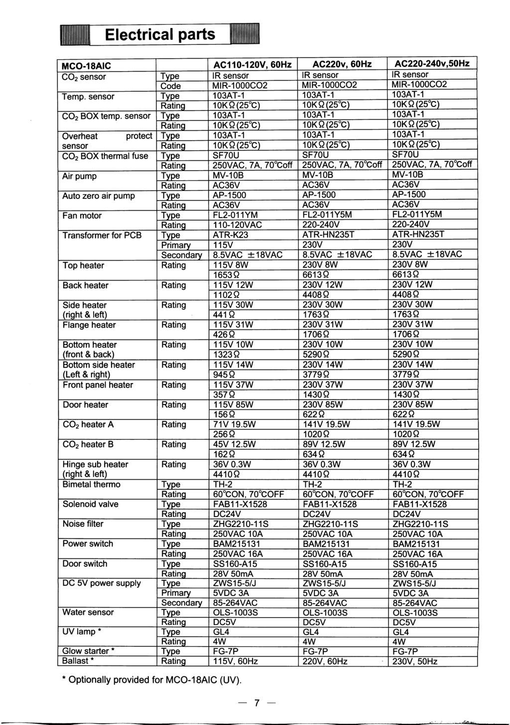
5
6 Performance specification Model Ambient temperature and humidity range Temperature control range in the unit Temperature distribution in the unit Temperature variation in the unit Temperature recovery period MCO-18AIC Temperature: 5 C 35 C Humidity: Less than 80%RH (In ambient temperature is lower than 15 C, original performance cannot be always obtained) Ambient temperature+5 C +50 C (Settable range:0 C 50 C) ±0.25 C ±0.1 C 25 minutes or less (until the internal temperature is recovered to 36.5 C after door opened for 30 seconds) CO 2 level range 0 20% CO 2 level distribution range ±0.15% CO 2 level recovery period Internal humidity Internal humidity recovery period Supplied CO 2 gas pressure Power supply Total power consumption Total current Quantity of radiation 10 minutes or less (until the CO 2 level is recovered to 4.5% after door opened for 30 seconds.) 95±5%RH 30 minutes or less (until the internal humidity is recovered to 90%RH after door opened for 30 seconds.) 0.03MpaG (0.3kg/cm 2 G) when the gas supplied Single phase, local voltage 310W VAC: Maximum 2.8A VAC: Maximum 1.4A Maximum 1120kJ/h Test condition: Set point: 37 C CO 2 set point: 5.0% No load Ambient temperature: 20 C Ambient humidity: Approx.45% Based on the measuring method on validation service manual. 3
7 Control specification Model MCO-18AIC Heating method Temperature control system Temperature indication CO 2 measuring system Direct Heat + Air jacket (DHA) Microprocessor PID Sensor: temperature sensor (103AT-1) Detect and control the inside temperature directly. Digital display (resolution: 0.1 C) Infrared CO 2 sensor, PID control CO 2 level indication Digital display (resolution: 0.1%) Humidifying system Inside air circulation Alarm system Door switch Remote alarm Self diagnosis function UV lamp control * Natural vaporization by water in humidify pan. Humidify pan: W293 x D407 x H41mm Breeze circulation High/low temperature alarm, high/low CO 2 level alarm Both display for temperature and CO 2 are flashing, and buzzer sounds intermittently after 15 min. Independent alarm for overheat Door lamp When outer door is opened: Inside fan OFF, CO 2 valve OFF, (UV lamp * OFF) and heater OFF (only when door is kept opening for 1 min. or more) When an alarm is triggered: Remote alarm ON (Alarm and buzzer are interlocked.) Contact output: rating of contact 30VDC, 2A Error code and internal temperature are displayed alternately. Buzzer and remote alarm contact ON Automatic ON-OFF control (changeable with Function mode) 1. Interlocked with the door: UV lamp ON for 5 min. after every door closed. 2. OFF mode (UV lamp does not turn on) * UV lamp is optionally provided. 4
8 Dimensions 5
9 6
10
11 Temperature calibration Note) When key lock mode is ON, calibration mode is disabled. (1) Press CAL key for approx. 5 seconds. (2) The top (the 3 rd ) digit of temperature display is flashing, other digits will go off. (3) Set the present correct temperature with key and key. Press ENT key. (4) The display will automatically revert to the present temperature. [Example] If the internal temperature display shows 37.0 C (the set value) and the actual measured value is 36.8, 1 Press CAL key for approx. 5 seconds. 2 The 3 (top digit) of temperature display is flashing, other digits will go off. Set the displayed value at 36.8 C of the actual measured value with key and key, then press ENT key. 4 The display will automatically revert to the present temperature. (Note) sin temperature calibration, it is important to accurately measure the internal temperature. Particularly, for the thermometer used, its grade of accuracy should be than 0.5 class. The measure should be carried out at the center of the chamber. sthe temperature calibration range is between the set value ±1.0 C. If the value over this range is input, an error tone will be emitted, the input data will be ignored, and the display will revert to the present temperature. Therefore, if you need to calibrate more than 1.0 C, you should repeat above procedure several times. 8
12 CO 2 Calibration Note) When key lock mode is ON, calibration mode is disabled. (1) Press CAL key for approx. 5 seconds. (2) The top (the 3 rd ) digit of temperature display is flashing, other digits will go off. (3)Press CAL keyagain. (4) The top (the 3 rd ) digit of CO 2 density display is flashing, other digit will go off. (5) Set the present correct CO 2 density with key and key. Press ENT key. (6) The display will automatically revert to the present temperature. [Example] If the internal CO 2 density display shows 5.0%(the set value), the actual measured value is 4.5, 1 Press CAL key for approx. 5 seconds. 2 The top digit of temperature display is flashing, and other digits will go off. Press CAL keyagain. 4 The top digit of CO 2 density display is flashing, other digits will go off. Set the displayed value at 4.5% of the actual measured value with and key, then press ENT key. 6 The display will automatically revert to the present temperature. (Note) s In CO 2 calibration, if CO 2 density display is less than 2.0%, an error tone will be emitted and the input data will be ignored, and the display will revert to the present temperature. s CO 2 calibration should be done after CO 2 density measuring was done at least three times after checked that there is no error of measurement. s This unit has auto zero adjustment function. It is necessary to check that the room installed the unit is not filled with CO 2 gas. If the unit is installed in smaller room, be sure to change the room air timely. (Please request to your customers.) s CO 2 calibration should be done in consideration of the difference for CO 2 density meter. key 9
13 Control specification 1. Key and switch BZ : When an alarm LED is flashing and the buzzer sounds, Buzzer and remote alarm output Force to turn off When an alarm lamp flashing and the buzzer does not sound, buzzer remains OFF. SET : Press once to enter the device into setting mode. Press twice to enter the device into CO 2 level setting mode. Press third times to enter the device into over-heat protection temperature check mode. Press four times to return the device to internal temperature (PV) display. : In the setting mode, the device can be shifted the 2 nd digit the 1 st digit the 1 st decimal place. In PV display, keep the key pressing 5 seconds or more to enter the key lock mode. : In the setting mode, the blinking digit counts up. CAL : Note) In PV display, keep the key pressing approximately 5 seconds to enter the device into the calibration mode, press again to enter the device into the CO 2 calibration mode. When the CO 2 setting value (SV) is 0%, the device goes into PV display instead of the CO 2 calibration mode. In the temperature calibration mode, input FXX with key and then press ENT key to enter the device into the function mode to obtain information of each mode. During CO 2 Auto Zero adjustment (the decimal point of indicator is flashing), the CO 2 calibration will not be performed with beeping the buzzer for a second continuously even if ENT key is pressed. ENT : During setting mode, CAL mode and Function mode, press the key to store the value. The function is not valid for the unchangeable values. A / B : The key is available only in optionally Auto-changer mode in F08. In Auto-changer mode, press the key to switch the cylinder in use to another one. Lighting A or B indicates as the cylinder in current use. (If the Auto-changer mode is not installed, the cylinder switcher lamp does not activate) When the cylinder in use is emptied, automatically switches to another one. At the time the lamp of cylinder emptied will blink, and the lamp of another one will illuminate. (Ex: When the CO 2 cylinder in current used is emptied, the lamp cylinder A switches to blink, and then the lamp cylinder B will illuminate) 2. Temperature control Setting range : Display range : 0 C~+50 C 0 C~+99.9 C Setting method : Press the SET key. Change to the desired value with key and key, then press the ENT key. The value will be stored and then the device shifts to CO 2 setting mode. Out of the range: Control When a value is set out of the range and ENT key is pressed, buzzer sounds 1 second (continuously) and the previous value is still remained. : PID control Alarm : When the PV is SV±1 C or higher, the display digit blinks. After 15 minutes later, buzzer sounds and remote output turns ON. 10
14 3. CO 2 control Setting range : 0%~20% Display range : 0%~99.9% Setting method : Press SET key twice. Change to the desired value with key and key, then press ENT key to store the value. Then the device shifts to the Overheat protection temperature check mode. Out of the range: When a value is set out of the range and ENT key is pressed, buzzer sounds 1 second (continuously) and the previous value is still remained. Control : PID Control Control OFF : When a value is set in 0.0%, CO 2 display will be disappeared to be the Control OFF. Alarm : When the internal CO 2 level deviates SV±1% or higher, CO 2 display blinks. After the 15mininutes later, buzzer sounds and remote alarm terminal turns ON. 4. Overheat protection temperature check mode Setting range : 35 C~51 C Settingmethod : Press SET key for three times to display the overheat protection temperature on PV display and HI on CO 2 display. Press SET key again to return to PV display. 5. Alarm, safety mode and self diagnosis In sensors malfunctions and CO 2 control malfunctions, an error code and PV is displayed alternately. Note) The remote alarm is controlled in every a minute exceptionally in Auto Zero. That s why the remote alarm control is delayed 4minutes (max) after an error is displayed. <Error code> E01: CO 2 cylinder is empty E05: Temp. sensor is open circuit E06: Temp. sensor is short circuit E07: CO 2 box temp. sensor is open circuit E08: CO 2 box temp. sensor is short circuit E09: Ambient temperature sensor is open circuit E10: Ambient temperature sensor is short circuit E11: CO 2 sensor output voltage is abnormal E12: Main heater is abnormal E13: Bottom heater is abnormal E14: Door heater is abnormal E15: CO 2 sensor box heater is abnormal E16: SSR for each heater is open circuit E17: Sample pump and/or Auto zero pump malfunction E18: UV lamp malfunction (a lamp blown out, a glow lamp unfitted, etc) The description of error codes are follow: E01 : CO 2 cylinder is empty When the CO 2 level is not 0.2% or more in a minute even though the valve is opened, E01 and Internal temperature are displayed alternately, and buzzer sounds intermittently. The definite action that CO 2 cylinder is empty, repeats twice, therefore it takes approximately 2minutes to display an error after the cylinder would be emptied. 11
15 E05,E06 : Note) E07,E08 : Temp. sensor malfunction (open / short circuit) When the micro-computer detects an internal temperature as 0 C or lower, it is judged as open circuit displaying alternately E05 with PV and sounding intermittent buzzer. When the micro-computer detects an internal temperature as +60 C or higher, it is judged as short circuit displaying alternately E05 with PV and sounding intermittent buzzer. In E05 and E06, displayed PV is different from product s actual temperature) CO 2 box temp. sensor malfunction (open / short circuit) See E05, E06 in details. (Note: In E07 and E08, CO 2 valve is closed) E09, E10: Ambient temperature sensor malfunction (open / short circuit) See E05, E06 in details. E11 E12 E13 E14 E15 E16 E17 : CO 2 sensor output voltage is abnormal When CO 2 sensor box temperature is stable and high or low temperature alarm is not occurred, it is judged as CO 2 sensor malfunction if CO 2 output voltage is lower than 1000mV or higher than 4800mV. E11 and internal temperature are displayed alternately, and buzzer sounds intermittently. At the time, CO 2 valve is closed. : Main heater is abnormal When high temperature alarm is activated, when the main heater is open circuit, and when the main heater SSR is short circuit, E12 and an internal temperature are displayed alternately and buzzer sounds intermittently. An error is not displayed just after failed because the self-diagnosis for SSR and heater failure is done only in every 40min or in the power supplied. (Above description is also applied for E13 - E16) : Bottom heater is abnormal When the bottom heater is open circuit, or SSR is short circuit, E13 and an internal temperature are displayed alternately, and buzzer sounds intermittently. : Door heater is abnormal When the door heater is open circuit, or SSR is short circuit, E14 and an internal temperature are displayed alternately, and buzzer sounds intermittently. : CO 2 sensor box heater is abnormal When the CO 2 sensor box heater is open circuit, or SSR is short circuit, E15 and internal temperature are displayed alternately, and buzzer sounds intermittently. : SSR is open circuit When any SSR of main heater, bottom heater, door heater and CO 2 sensor box heater is open circuit, E16 and an internal temperature are displayed alternately, and buzzer sounds intermittently. : Sample pump and Auto zero pump malfunction In CO 2 SV is 3.5% or higher and the current level is 3.5% or higher, if the difference of voltage between during Auto Zero and before Auto Zero is 150mV or lower, it judges as Sample pump and Auto zero pump malfunction. E17 and an internal temperature are displayed alternately and buzzer sounds intermittently. At the same time CO 2 valve is closed. The judgement would be done in every Auto Zero adjusts, however, the judgement in the 1 st interval in Auto Zero would be ignored. 12
16 E18 : UV lamp malfunction (UV lamp is optionally provided) When the time to turn the UV lamp on (F01) is set, the microcomputer checks the output voltage in UV detect circuit, that is detected 30seconds after the door was opened shut. If the detected voltage is 0.2V or lower, it is judged as UV lamp malfunction. E18 and internal temperature are displayed alternately, at the time the buzzer sounds intermittently. Press BZ key to cancel the error. High temperature alarm: When the internal temperature is out of SV, OVERHEAT lamp illuminates displaying PV with E12 (main heater malfunction) or E16 (SSR for each heater is open circuit) alternately. The buzzer sounds intermittently. It is impossible to stop the buzzer sounding by BUZZER key. At the time heaters (main heater, bottom heater and door heater) will be OFF. Automatic temperature alarm When the internal temperature is ±1.0 C out of SV, all digits in temperature display blink and intermittent buzzer sounds with 15minutes delay. Automatic CO 2 level alarm When the internal CO 2 level is 1.0% out of SV, all digits in CO 2 display blink and intermittent buzzer sounds with 15 minutes delay. CO 2 Auto Zero adjustment calibration: See details in Auto Zero adjustment, Page Key lock function Lock mode : Note) In PV display, keep pressing key (shift key) over 5 seconds to enter key lock mode, display will change to L0. Press key to set 1 Key lock ON Press key to set 0 Key lock OFF Press SET to memorize the set, then automatically returns to PV display. In Key Lock ON, the device can enter into SET mode to check SV, however, the value cannot be changed. The device also cannot enter into Function mode. 7. Door alarm Display Safety operation : : When the door is opened, DOOR lamp illuminates. When the door is closed, DOOR lamp goes off. When the door is opened, fan motor turns off, CO 2 valve shuts off, (UV lamp turns off if it is optionally fitted). If the door left opened for 60seconds, the heater turns off. 8. Auto return Function : In setting mode, Key Lock mode and Function mode, if any key is not operated for 90 seconds or more, the display automatically returns to PV without storing the value to be changed. 9. Calibration Temperature calibration : In PV display, press CAL key for approx. 5seconds to enter the device into temperature calibration mode. Input a proper value with key and key then press ENT key to store the value. Finally the device returns to PV display. 13
17 CO 2 calibration : In PV display, press CAL key for approx. 5seconds to enter the device into temperature calibration mode, then press CAL key again to enter the device into CO 2 calibration mode. Input a proper value with key and key then press ENT key to recognize and store a span calibrated value. Finally the device returns to PV display. (a span adjustment) If CO 2 level is lower than 0.9% or higher than 20% on the display, or if a value to calibrate is higher than 2.0%, the buzzer beeps to cancel the data input then automatically returns to PV display. During Auto Zero adjustment (the decimal point of the 2 nd digit is blinking on CO 2 display), CO 2 calibration cannot be performed. 10. Function mode F00: Simply pass through. F01: Time length of UV lamp illuminating is changed. (initial: 000) (UV lamp is optionally provided) F02: UV lamp 24hours sterilization mode set (UV lamp is optionally provided) F03: Service code input (code: 384) F04: UV lamp life span check (UV lamp is optionally provided) F05: Display the voltage in CO 2 sensor F06: Change the output ratio of bottom heater (initial:12) F07: Change the output ratio of door heater (initial: 4) F08: Auto changer, DEMO mode, Auto Zero mode set (initial : 000) F09: Display a temperature in CO 2 sensor box F10: Display a coefficient of adjustment value for CO 2 zero point F11: Display a coefficient of adjustment value for CO 2 span point F12: Display the temperature in ambient temperature sensor F13: Initialize non volatile memory F14: LEDs and drivers performance check F15: Display a value to adjust zero point in temperature (initial: 008) F21: Communication device address (ID) set (initial: 000) F22: Communication parameter set (initial: 000) F24: Interlock the remote alarm with buzzer (initial: 000) F25: Ring Back time set (initial: 030) F30: Display ROM version Direction for use: In PV display, press CAL key for 5seconds or more to enter the device into temperature calibration mode. Input a desired function code with key and key then press ENT key. F01: Time length of UV lamp illuminating is set. (initial: 0min, range:0~30min) Note) UV lamp is optionally provided. Input F01 on the temperature display then press ENT key to show a present SV on the CO 2 display. Input the desired value with key and key then press ENT key to store the value. Finally returns to PV. If a value out of the range is input then ENT key is pressed, the buzzer beeps for a second continuously to keep the previous set. <Direction for use> <Action> After the door is opened and shut, UV lamp illuminates in appointed time then automatically goes off. There is approx. 3~5seconds delay to active the mode, due the device would check water level in the humidify pan just after the door shut. With UV lamp illuminating, the lamp goes off if the door is opened. 14
18 F02: UV lamp 24hours sterilization mode set Note) UV lamp is optionally provided. Input F02 on temperature display to show 000 on CO 2 display. Input 001 with key and key to enter the device into 24hours sterilization mode. At the time press ENT key displaying with 001 to simply return to PV display. <Direction for use> <Action> When 24hours sterilization mode is set in F02, UV lamp starts illuminating and automatically goes off after 24hours has passed. In the middle of 24hours sterilization, if the door is opened, UV lamp goes off and 24 hours sterilization mode would be cancelled. If 24hours sterilization mode is reset in the middle in F02, the mode would start operation from the beginning. Note) UV indicator lamp should illuminate when UV lamp illuminates, so the indicator lamp illuminates if UV lamp is unfit. F03: Note that those who knows service code (384) should use F04 or the following functions (except for F21, 22, 24, 25 and 30). <Direction Input the following code to use the following functions. (code: 384) for use> Input F03 on temperature display then press ENT key to show 000 on CO 2 display. ( 384 is appeared if service code has been already input) Input service code 384 with key and key, and press ENT key to return to PV display. Now F04 and the following functions are available. If F03 or a following function code instead of the above code is input in F03, for example if F05 is input then ENT key is pressed, the continuous buzzer beeps for a second to return to PV display. In this case input the above code to enter the device into F04 or a following function. Note) The above code is stored unless 000 is input in F03 or the mains is OFF. F04: Display life span of UV lamp Note) UV lamp is optionally provided. <Direction Input F04 on temperature display and press ENT key to show UV lamp used for use> time (a period to turn UV lamp on) by unit of %. <Description> The microcomputer calculates UV lamp whole life span as 1000hours. A period to turn UV lamp on is displayed in the unit of %. For example, the period less than 5minutes is considered as 5minutes, the period of 6~30minutes is simply counted as they are. In 24hours mode, simply 24hours is added just after 001 is input and ENT key is pressed in F02, ignored with the cancel for 24hours mode caused by the door is opened in the middle. The added value is stored in the non-volatile memory in every 24hours. Display the added value in F04 then display 000 on CO 2 display with key and key and press ENT key to clear the value. The display range is 0~260%. A value over than 260% is not added. If the added period is over than 1000hours, UV indicator on the control panel flashes to inform UV lamp run down. The run down is provided by the microcomputer s calculation, it does not mean the actual time to be UV lamp run down. UV lamp life span UV indicator on the control panel UV lamp ON UV lamp OFF 1000hours or less Illuminates Goes off 1000hours or more Illuminates Flashes 15
19 F05: Display the voltage in CO 2 sensor (A/D converter voltage in microcomputer on the main PCB) <Direction Input F05 on temperature display and press ENT key to show the voltage in for use> CO 2 sensor on CO 2 display. Press ENT key to be Auto Zero forcibly performed within a minute. Since the 90seconds Auto Return is invalid in this mode, press ENT key to come to the end. F06: Adjust humidity level by changing the electricity output ratio in the bottom heater. (initial: 12, the range: 0~19) <Direction Input F06 on temperature display and press ENT key to show a current SV on for use> CO 2 display. Sum the value up to make humidify higher. Lessen the value to make humidify lower. Press ENT key to store the value and automatically returns to PV display. F07: Prevent dew condensation by changing the electricity output ratio in the door heater. (initial: 4, the range: 0~9) <Direction Input F07 on temperature display and press ENT key to show a current SV on for use> CO 2 display. If there is dew condensation on the door, sum the value on CO 2 display up and press ENT key to store the value and automatically returns to PV. F08: Auto Zero and Auto Changer ON/OFF set, Demonstration mode set (initial: 000) In Auto Changer mode, both of CO 2 cylinders are available when CO 2 is requested to supply. A lamp of cylinder in current used (either lamp-a or lamp-b) is illuminated to switch manually one to another with A/B key. If the cylinder in current used is empty, automatically switches to another cylinder and the lamp of empty cylinder flashes. In Demonstration mode, SV for both temperature and CO 2 are displayed, it seems to be under control. At the time the heater is not conducted and CO 2 valve is not opened. (Demonstration mode is used in exhibitions.) <Direction for use> In Auto Zero, zero adjustment for CO 2 sensor is automatically performed based in ambient air. Auto Zero is performed per every 10minutes in 1 hour when the main power is supplied, after that it is performed per every 4hours. Auto Changer mode setting (in the 3 rd digit on CO 2 display) Input F08 on temperature display and press ENT key to show a current SV in the 3 rd digit on CO 2 display. The value 0 is the normal mode (Auto Changer is inoperative), the value 1 is Auto Changer is operative. Demonstration mode setting (in the 2 nd digit on CO 2 display) Input F08 on temperature display and press ENT key to show a current SV in the 2 nd digit on CO 2 display. The value 0 is the normal mode (Auto Zero is operative), the value 1 is Demonstration mode is operative. Change the 2 nd digit to a desired digit and press ENT key to return to PV display. Auto Zero setting (in the 1 st digit on CO 2 display) Input F08 on temperature display and press ENT key to show a current SV in the 1 st digit on CO 2 display. The value 0 is the normal mode (Auto Zero is operative), the value 1 is Auto Zero is inoperative. Change the 1 st digit to a desired digit and press ENT key to return to PV display. 16
20 F09: Display the temperature in CO 2 sensor box <Direction for Input F09 on temperature display and press ENT key to show the use> temperature in CO 2 sensor box. If you press ENT key or leave for 90seconds, automatically returns to PV display. In SV is +45 C, CO 2 valve turns OFF when the temperature is out of SV±2.0 C. Once the temperature retrieves in SV±2.0 C, Auto Zero is forcibly executed since the apparatus falls into the condition that the main power is supplied. When CO 2 is not injected, the temperature in sensor box may be out of ±2.0 C, or it may be within 60minutes after the main power is supplied, or Auto Zero may be being executed. <Direction for use> F10: Display a coefficient of adjustment value for CO 2 zero point (initial: 500) Input F10 on temperature display and press ENT key to display a coefficient of adjustment value for CO 2 zero point on CO 2 display. If you press ENT key or leave the device for 90seconds, automatically returns to PV display. <Description> The condition is that CO 2 sensor voltage should be adjusted in 4.0V when internal CO 2 level is 0%. Perform Auto Zero and ensure the sensor output voltage should be approx. 4.0V when ambient air is got properly by the pump. At that time the value should be approx If CO 2 in the ambient air is several %, the value would be lower than 500 since CO 2 sensor output voltage is lower than 4.0V. <Calculation> Note) <Direction for use> (CO 2 sensor output voltage during Auto Zero pump performs / 4.0V) x 5000 Only bigger three digits are displayed. e.g 5000 displayed as 500 F11: Display a coefficient of adjustment value for CO 2 span point (initial: 500) Input F11 on temperature display and press ENT key to display an adjustment value for CO 2 zero point on CO 2 display. If you press ENT key or leave the device for 90seconds, automatically returns to PV display. <Description> The value is adjusted when CO 2 is calibrated. For example, calibrate CO 2 with SV 4.5% when the CO 2 level is displayed as 5.0%, however the actual level is 4.5%. At that time the value in F11 should be lower than 500, ex 460. If the value is abnormal, ex 999, the actual internal level can be 1.0%, however the CO 2 is displayed as 5.0%. <Direction for use> <Direction for use> F12: Display a temperature in ambient temperature sensor Input F12 on temperature display and press ENT key to display a temperature of ambient temperature sensor on CO 2 display. If you press ENT key or leave the device for 90seconds, automatically returns to PV display. Note) This temperature is not synchronized with actual ambient temperature since it is affected by waste heat in electrical parts. (indicated approx. 4 C higher than the actual temperature) F13: Initialize the non-volatile memory (initial: 000) This function should be used only when data in the non-volatile memory cannot be restored owing to unexpected events (ex: noise). Do not use in normal condition. Input F13 on temperature display and press ENT key to display 000 on CO 2 display, then change the 1 st digit to 1 and press ENT key to initialize all the data in non-volatile memory. 17
21 Followings are initial values in non-volatile memory: Internal temperature SV : 37.0 C CO 2 level SV : 0.0% Balance value of humidifying heater (F06) : 12 Balance value of door heater (F07) : 4 CO 2 zero adjustment data (F10) : 5000 CO 2 span data (F11) : 5000 Internal temperature zero adjustment data (F15) : 008 Key Lock data : Key Lock OFF Auto Changer data (the 3 rd digit in F08) : Auto Changer OFF Demo Mode data (the 2 nd digit in F08) : Demo Mode OFF Auto Zero (the 1 st digit in F08) : Auto Zero ON Input F13 on temperature display and press ENT key to display 000 on CO 2 display, then change the 1 st digit to 2 and press ENT key to initialize CO 2 zero adjustment data and CO 2 span data in non-volatile memory. Note) Service code should not be initialized. F14: Check the performance for LED, drivers <Direction for Input F14 on temperature display and press ENT key to perform with lamp use> and the all digits flashing at every 0.5seconds intervals. Press ENT key to stop performance. If there is no key operation for approx. 90seconds, automatically comes to end <Direction for use> F15: Display an adjustment value for temperature zero point (initial: 0.8 C) Input F15 on temperature display and press ENT key to display an adjustment value on CO 2 display for temperature zero point. If you press ENT key or leave the device for 90seconds, automatically returns to PV display. (Ex.) In 37.0 is displayed on the control panel and actual temperature is 37.8, if you perform temperature calibration (actual temperature 37.8 is input), +0.8 would be housed in F15. In Function Mode, input F15 and press ENT key to display the value on CO 2 display. F21: Set serial communication ID (initial: 000) <Direction for Input F21 on temperature display and press ENT key to show 000 on CO 2 use> display. Then input the value that identifies the product (serial communication ID Number) and press ENT key to set serial communication ID. The range is 000~255. (000: communication OFF) F22: Set serial communication mode (initial: 000) <Direction for Input F22 on temperature display and press ENT key to show 000 on CO 2 use> display. Then change the 3 rd digit to set the communication mode. Control mode (the 3 rd digit) 0: Local (initial) 1: Remote Baud rate (the 2 nd digit) 0: 2400bps 1: 4800bps 2: 9600bps F24: Interlock the remote alarm with buzzer (initial: 000) <Direction for Input F24 on temperature display and press ENT key to show 000/001 on use> CO 2 display. Then change the 1 st digit to 000 to set the interlock mode. 000: Buzzer/Remote alarm not interlocked 001: Buzzer/Remote alarm interlocked 18
22 F25: Ring Back time set (initial: 030 (30min), the range: 0~60min) <Direction for Input F25 on temperature display and press ENT key to set current Ring use> Back delay time. Change the 2 nd digit to set delay time in the range of 0~60min. Note) Ring Back time set, F25 = 000 means BZ would not comeback (in former spec) F30: Display the ROM version <Direction for Input F30 on temperature display and press ENT key to show current ROM use> version on CO 2 display. 11. Bottom heater control In order to shorten the recovery time of humidity, conduct electricity to humidity heater as follows. In the ordinary, the maximum electricity conduct to bottom heater should be in the ratio of 80%. When the internal temperature is SV-0.4~-0.6deg, conduct 80% electricity to humidify heater for 10minutes (max). SV in F06 is applied except for above temperature. 80% electricity conduct should not be performed in the following cases: 1) The period until an internal temperature reaches to SV-0.2deg after the power is supplied 2) The period until an internal temperature reaches to SV-0.2deg after the door is left opened continuously for 60seconds or more. 12. Door heater control Ordinarily, conduct electricity to door heater in the same ratio with main heater. SV in F07 is applied. 13. Remote alarm: remote alarm contact In normal condition... Open In alarming condition Close Note) The recovery time after BZ key is pressed and linkage between remote alarm and buzzer are depending on F24, F25 setting. 14. Storing in non-volatile memory 2 times comparison method: When the main power is supplied, a data storing in non-volatile memory is called for 2 times to compare. If the data 1 st called coincides with the data of 2 nd called, the data would be stored in RAM. Otherwise, the comparison would be repeated until the one coincides with another. 15. Temperature offset value The difference between temperature sensed in temperature control sensor and temperature in internal 1/2H should be offset: Offset value: +0.8 C 16. Example for displays Current temperature C CO 2 level +5.0% Set temperature C Auto Zero adjusting Function F03 Auto Zero adjustment value 5021 (Service code input) CO 2 gas error E01 Bottom heater ratio 004 Lock Mode L 0 19
23 Wiring Diagram 20
24 Circuit Diagram 21
25 Components on PCB 22
26 Connection on PCB The following shows connections of connector (CN) on main PCB. Connector Connects to Use Power transformer CN1 CN2 Between #1 #2, AC8.5V #3 GND #4 and #5, AC18V Power supply Between #1 #2(GND), DC5V To supply the power to PCB. To supply the power AC36V for Auto zero air pump. To supply the power to PCB. CN3 CO 2 sensor Input from CO 2 sensor. CN4 #1 #2 #3 #4 #5 #6 Overheat protect sensor Temperature sensor CO 2 box temp. sensor To measure the temperature of each parts. CN6 Door switch To detect the door opening. CN8 CN9 CN10 CN11 CN12 Switch, display PCB (CN101) #1 #2 CO 2 valve #3 #4 CO 2 auto changer valve (option) Remote alarm output #1 #2 Open during normal operation Communication board (option) #1 #2 Auto zero air pump #3 #4 Air pump hinge sub heater CN13 Buzzer For alarm To control CO 2 valve ON and OFF. Output of remote alarm contact CN14 UV lamp relay (option) CN15 Water sensor To check water level in humidify pan. CN101 Display PCB (CN8) The following shows connections of connector (CN) on power PCB. Connector Connects to Use CN301 CN302 C303 Main PCB #1: Heater for heat control (5pcs) #3: Bottom heater (4pcs) #5: Front panel heater, Door heater (2pcs) #1: CO 2 A, B heater #3: Agitating fan motor To control heater To control the sensor BOX temperature. To control the pump for circulation. 23
27 CO 2 gas circuit Auto Zero air pump 25mm Cap. tube Filter Air pump 25mm Cap. tube Solenoid valve CO 2 sensor T-connector Filter Filter Gas supplied Sample port (front) < Back view > 24
28 Prevention of contamination In servicing for CO 2 incubator, it is important to prevent from contamination. (1)More than 90% of contamination in CO 2 incubator is caused by mold. Mold is a kind of true fungi, it has high increasing power under high temperature and high humidity. Accordingly, it is easy for mold to increase inside CO 2 incubator. Those increased mold eat up culture (mainly animal cell), eventually precious test sample will be killed. Cell that is independent from ecosystem is also independent from immune system, it has no immunocompetence at all. (2)Precautions for mold increasing There are many cases that mold is increasing by eating fat on the fingers as a source of nutrient in CO 2 incubator. Therefore, Be sure to wash and sterilize your hands prior to servicing. Use 70% ethanol. In installing, sterilize the inside wall and shelves after removing shelves, duct, humidifying pan and so on with 70% ethanol. (3)In the case that mold is already increasing. Sterilize the interior (walls) and shelves with 70% ethanol after removed all items from the chamber as same as (2)- above. And you should sterilize again after 24 hours once sterilized, when the root of spore is geminated, because it is too difficult to remove spore of mold. Repeat sterilization is effective. NOTICE In general, stainless steel is known that it is not easy (hard) to rust. However depends on the conditions, rust might generate. When you remove rust, we recommend the following agents. Besides, the surface may become foggy. Recommended agent: 1. Cream cleanser Gif (Nippon Leva) 2. Picasso #SUS300-W (Chemical YAMAMOTO) <Picasso has greater capability of clean for rust than Gif.> 25
29
30 CO2 gas density calibration and Auto Zero adjustment MCO-18AIC provides both the manual CO 2 gas density calibration and the automatic Auto Zero adjustment. 1. CO 2 gas density calibration When either the CO 2 density SV or the display value is not match with the actual value, calibrate CO 2 gas density according with CO 2 calibration (Page 9) to input the actual value again. 2. Auto Zero adjustment Refer to Auto Zero adjustment 3. The relation the CO 2 gas density calibration with the Auto Zero adjustment The description is as follow.(ex: CO 2 density = 5%) Actual density(%co2) 5 Ideal line for the set value and the actual value. (Note) In fact, it could not make a straight line due to the characteristics of the sensor. Point calibrated by CO 2 gas density calibration Set density(%co 2 ) Point calibrated by auto zero adjustment 27
31 Specifications of sensor Temperature/Resistance for temperature sensor 103AT-1 The measure of internal temperature (internal temperature, overheat protection) and ambient temperature Temperature ( C) Resistance (kω) Temperature ( C) Resistance (kω) Temperature ( C) Resistance (kω) Specification for CO 2 density/output voltage in IR sensor (Output voltage = amplify value in main PCB) CO 2 density (%) R13 output voltage(v) CO 2 density (%) R13 output voltage(v) CO 2 density (%) R13 output voltage(v) Followings are reference voltage. In actual use, it is no problem if the calibration could be done in reliable CO 2 density. 28

32 Parts layout agitating fan motor monitoring hole Auto Zero air pump Remote alarm terminal CO2 valve filter CO2 gas inlet 29


 30")
33 remote alarm terminal sensor BOX transformer for PCB noise filter sensor BOX temp. sensor thermal fuse sensor BOX heater CO2 IR sensor power comsumption resistance (R13) 30


34 CO2 gas inject port Overheat protect sensor Temp. sensor Inlet port of Sampling gas for CO 2 sensor Return port of Sampling gas for CO 2 sensor UV lamp connection port Water level sensor 31
35 MCO-18UVS Installation Procedure Kit of MCO-18UVS 1 UV label 1 UV lamp 1 UV caution label 1 UV door switch caution label 1 UV lamp cover 1 ballast & glow assy q 1 Name plate 6 screws (M 4) r 1 Patent label Procedure 1. Unplug the unit and make sure that power is not supplied to the unit. 2. Remove the duct from inside the unit, then take off 2 caps and 2 screws shown in Fig Take out two insulations for the UV lamp lead wire hole shown in Fig. 3. The insulation can be taken out easily by pushing it from inside of the chamber. Keep the insulation for the future use again. Screw Cap Fig.1 Insulation Fig.3 3. Take off the rear cover shown in Fig Set the UV lamp to the hole and make sure to be fitted properly. Fix the UV lamp cover with 2 screws enclosed in this kit. Rear cover Screw UV lamp cover UV lamp Fig.2 Fig.4 32
36 6. Replace the duct. Place the humidifying tray, then cover the tray with the humidifying tray cover as shown in Fig Remove a cap shown in Fig. 7. By using 4 screws enclosed with this kit, fix the ballast/glow assy as shown in Fig. 7. Humidifying tray cover Fig.5 Screw ballast & glow assy Fig.7 Cap 7. Replace the insulation into the UV lamp lead wire hole with the wire passed through the cut on the insulation. See Fig.6 UV lamp lead wire Insulation Fig.6 33
37 9. Connect each lead wire connector of ballast/glow assy, as shown in Fig. 8. Connect after removing the cover. BLUE Cover GREEN Fig Attach the labels. UV door switch caution label Name plate UV label UV caution label Patent label Fig.9 34
38 11. Set the UV lamp ON period through control panel When using UV lamp option, it is needed to set the UV lamp ON period. Refer to the following procedure. Description of operation Key operated Indication after operation 1 Turn the power switch ON. The current chamber temperature is - displayed. 2 Press CAL key for 5 seconds. CAL The left digit in the temperature indicator is flashed. 3 By pressing key and key, set the figure to F01. F Press ENT key. 5 By pressing key and key, set the figure to 005 (5 minutes of ON period). 6 Press ENT key. ENT ENT In CO 2 density indicator, "000" is displayed and the right digit is flashed. F F The setting of UV lamp ON time is memorized and the current chamber temperature is displayed. <<NOTE>> The UV lamp ON time is settable between 0 to 30 minutes. However, it is recommended to set 5 minutes in general. The UV lamp ON time is settable between 0 to 30 minutes (000 to 030). The UV lamp is not turned ON if the setting is 000. The UV lamp is turned off when the outer door is opened while the lamp is on. The lamp is turned on for pre-set duration after the outer door is closed. The condensation in the chamber can be caused and/or the chamber temperature distribution can be affected due to the heat from UV lamp when the setting of UV lamp ON time is longer than 5 minutes or the only the outer door is opened/closed repeatedly. In such case, the life of UV lamp is shortened. In the procedure 2 above, pressing CAL key for 5 seconds causes the calibration mode. In this mode, it is possible to calibrate the temperature and CO 2 density, and miss operation of the key may affect the basic performance of the unit. Take care of the key operation. Even if the key is operated wrongly, the unit returns to the current value display mode automatically when no key is operated for 90 seconds. In this case, the setting not entered by pressing ENT key is not effective. 12. Check that the UV lamp is turned on. Check the UV lamp is turned on by the following procedure: Procedure 1 Open the outer door and push the door switch with the inner door is closed. 2 Check that the UV indicator on the control panel is on after a few seconds. 3 Check the visible blue light from the front side of the humidifying pan cover. (Check the light with the inner door closed. Never look at the UV light directly.) 35 7FB6P
39 Mounting Procedure of MCO-21GC (Automatic CO 2 cylinder changer for MCO-20AIC/18AIC) Parts list CO 2 valve assy y-pipe assy connecting port for CO 2 gas pipe nut spring washer tube band (L) tube band (S) screw tube tube L100 (Used for MCO-18AIC ONLY) Before mounting This kit is applicable to both MCO-20AIC and MCO-18AIC. Following procedure is necessary only when mounting to MCO-18AIC. 1. Remove the tube band on the CO 2 valve assy, and then remove the hose and capillary. 2. Attach the tube L100 and fix the tube by the tube band removed in procedure 1. Make sure the tube band is fixed firmly to prevent gas leakage. CO 2 valve assy tube band tube L100 Remove the tube and capillary Fix the edge by the tube band Fig.1 36
40 Mounting procedure 1.Disconnect the power cable and make sure that the unit is not supplied with the power. 2.Remove the rear cover by unscrewing the 6 fixing screws. 3.Fix by using the enclosed screws( ). 4.Remove cap and fix with and. 5.Connect the wiring harness of CO 2 valve B to wiring harness from CN9 on Main board. 6.Disconnect upper tube of CO 2 valve A. Connect CO 2 valve A and CO 2 valve B and tube X by using as shown in Fig.4. 7.Connect bottom tube of to. 8.Connect with CO 2 gas supply line B by using. 9.Fix tubes securely using and as shown in Fig Replace the rear cover. Rear cover Fig.2 NOTE: Every tubes should be connected surely to prevent CO2 leakage. Tube X CO 2 valve B CO 2 valve A white Main board CN9 CO 2 gas supply line A cap yellow CO 2 gas supply line B Fig.3 Fig.4 37
41 Setting procedure of Control panel. When use MCO-21GC(the automatic CO 2 cylinder changer system), it is necessary to set the MCO-20AIC/18AIC automatic gas switching mode according to the following procedures. Description of operation 1 Turn the power switch ON. 2 Press CAL key for 5 seconds. 3 By pressing key and key, set the figure to F03. Key operated - CAL Indication after operation The current chamber temperature is displayed. The left digit in the temperature indicator is flashed. F Press ENT key. 5 By pressing key and key, set the figure to 384 ENT In CO 2 density indicator, "000" is displayed and the right digit is flashed. F F Press ENT key. 7 Press CAL key for 5 seconds. 8 By pressing key and key, set the figure to F08 9 Press ENT key. 10 By pressing key and key, set only the left digit figure to 1. NOTE:Don't change center digit figure and right digit figure. 11 Press ENT key. ENT CAL ENT ENT The current chamber temperature is displayed. The left digit in the temperature indicator is flashed. In CO 2 density indicator, "0**" is displayed and the right digit is flashed. F 0 8 F * * F * * " * " means "0" or "1". Setting of MCO-21GC is finished. The current chamber temperature is displayed. CO 2 gas supply line indicator A is lighted. 38
42 Procedure for automatic gas switching operation check. When the installation of MCO-21GC is completed, check the automatic gas switching operation according to the following to the following procedures. procedure 1 Stop the gas supply of cylinder A and use cylinder B only for CO 2 gas supply. 2 Turn on the power switch of MCO-20AIC/18AIC and set 37decC and 0%. Turn on CO 2 gas supply line indicator with CO 2 gas supply line switching key. 3 Wait for 1 hour approx, until the machine can control the CO 2 density. (It takes about 1 hour from turning on the power switch until CO 2 control is enabled.) 4 Set CO 2 density 5% and check the CO 2 inject lamp turns on. NOTE: In case of low ambient temperature, it may take more than 1 hour until the machine can control CO 2 density and the CO 2 inject lamp turns on. 5 Check the E01(CO 2 gas cylinder empty alarm) and buzzer turn on about 2-7minutes later from the CO 2 inject lamp's turning on. 6 Check the CO 2 gas density indicator reaches to the set value 5% and keep it stably. NOTE: CO 2 density control is interrupted when automatic calibration of CO 2 sensor is activated and the decimal point of CO 2 density indicator blinks. 7 All the procedure are completed. Shut down the CO 2 supply of cylinder A and cylinder B. Turn off "E01" display with the buzzer key and select cylinder A with CO 2 gas supply line switching key. Turn off the main power switch. Refer to the MCO-20AIC/18AIC instruction manual for usage of MCO-21GC 39 7FB6P
43 HOW TO REPLACE WATER LEVEL SENSOR. 1.Unplug the unit and check that power is not supplied to the unit, then take the rear cover off. 2.Unfasten the connectors for lead wire and take out the insulation for the lead wire hole. Water level sensor lead wire connector Insulation for the lead wire hole Fig.1 3.Take out the duct from inside. 4.Unfasten the 2 screws to remove unit of water level sensor and installation grommets for water level sensor. 5.replace water level sensor. Note Be sure to set the water level sensor to the right direction. 6.Place back the water level sensor, Water sensor installation grommet as before. 7.Place back the insulation material to the hole for the lead wire. Note Be careful for the length of lead wire for water level sensor inside the unit Length is connect 2 nd binder is located where it touches the water level sensor grommet. (refer to Fig.3) 3.Put the rear cover in place screw Water level sensor Fig.2 Water level sensor Installation grommet Water level Sensor grommet binder Fig.3 40
44 MCO-18PS Installation Procedure Kit of MCO-18PS 2 Stacking plate B 2 Stacking plate A 4 Protective sticker 4 Screws Procedure <When stacking 2 units of MCO-18AIC> 1. Turn off the power switch and disconnect a plug of each unit. 2. Check that the lower unit is level. 3. Apply the protective sticker enclosed in this kit at each corner on the top of the lower unit to avoid scratches or damage. 4. Fix the stacking plate A at 2 locations on the top front of the lower unit by using 2 screws enclosed in this kit. 5. Remove the front panel on the upper unit by unscrewing the 4 fixing screws and then disconnect the wires and gas tube. 6. Stack the unit so that both units can be aligned straight. Also check the upper unit is level. If it is not level, keep the unit even by adjusting the leveling legs. 7. Secure the upper unit with the stacking plate A and 2 screws enclosed in this kit. 8. Remove 2 hooks on the rear side of the lower unit by unscrewing each 2 fixing screws. 9. Remove 1 screw on the bottom right and left on the rear side of the upper unit. 10. Fix the stacking plate B at the right and left on the rear of the lower and upper unit with 3 screws removed in step 8 and Replace the front panel on the upper unit after connecting the wires and gas tube. 12. Fix the stacked unit to the wall with 2 hooks on the rear of the upper unit and rope or chain. Front panel Stacking plate B Hook Stacking plate A Protective sticker 41 Fig.1
45 <When stacking of combination as shown in Fig.2.> MCO-17AIC MCO-17AC MCO-15AC MCO-18AIC MCO-17AIC MCO-17AC MCO-15AC MCO-18AIC MCO-17AIC MCO-17AC MCO-15AC MCO-17AIC MCO-17AC MCO-15AC Fig.2 1. Turn off the power switch and disconnect a plug of each unit. 2. Check that the lower unit is level. 3. Apply the protective sticker enclosed in this kit at each corner on the top of the lower unit to avoid scratches or damage. 4. Stack the unit so that both units can be aligned straight. Also check the upper unit is level. If it is not level, keep the unit even by adjusting the leveling legs. 5. Remove 2 hooks on the rear side of the lower unit by unscrewing each 2 fixing screws. 6. Remove 1 screw on the bottom right and left on the rear side of the upper unit.(only MCO-18AIC) 7. Fix the stacking plate B at the right and left on the rear of the lower and upper unit with 3 screws removed in step 5 and enclosed in this kit. 8. Fix the stacked unit to the wall with 2 hooks on the rear of the upper unit and rope or chain. Stacking plate A is not used. Stacking plate B Hook Protective sticker Fig.3 WARNING Select a level and sturdy floor having enough strength for installation of stacked module. Never stack 3 or more units. Take care not to drop or tip over the unit when stacking as this can cause injury or damage of the unit. 42 7FB6P
46 MCO-18SB Setting Procedure (Stacking base for stacking MCO-18AIC/17AIC/17AC/15AC on MCO-175/175M) 1.Remove four clips on the top of lower unit. 2.Fasten four Fixing screws A tentatively from where the clips were remove. 3.Set the Stacking base and fix with screws tentatively fastened. 4.Stick the Protective sticker on the Stacking base as shown in Fig.1. 5.In case of stack MCO-18AIC Put the upper unit on it. Fix the upper unit with Front fixing plate, Rear fixing plate. ( Rear fixing plate R and Rear fixing plate L are not used.) In case of stack MCO-17AIC/17AC/15AC Put the upper unit on it. Fix the upper unit with Front fixing plate, Rear fixing plate R, and Rear fixing plate L. ( Rear fixing plate is not used.) 6.Check the both units are level. NO. Parts name Q ty Stacking base 1 Front fixing plate 2 Rear fixing plate R (for 17AIC/17AC/15AC) 1 Rear fixing plate L (for 17AIC/17AC/15AC) 1 Rear fixing plate (for 18AIC) 2 Protective sticker 2 Fixing screw A 4 Fixing screw B 8 ( ) ( ) Fig.1 Fig FB 6 P
47 MCO-21SB Setting Procedure (Stacking base for stacking MCO-18AIC/17AIC/17AC/15AC on MCO-20AIC) 1. Stick the Buffer rubber at each corner on the bottom of Stacking base. Stick the Protective sticker on the Stacking base as shown in Fig Attach the Base mounting plate onto the top of MCO-20AIC by using Fixing screw B. 3. Remove 2 hooks on the rear side of MCO-20AIC. 4. Fix the Stacking base onto the top of MCO-20AIC by using Fixing screw A and 2 screws removed in step In case of stack MCO-18AIC Put the upper unit on it. Fix the upper unit with Front fixing plate, Rear fixing plate. ( Rear fixing plate R and Rear fixing plate L are not used.) In case of stack MCO-17AIC/17AC/15AC Put the upper unit on it. Fix the upper unit with Front fixing plate, Rear fixing plate R, and Rear fixing plate L. ( Rear fixing plate is not used.) 6. Check the both units are level. No. Parts name Q ty Stacking base 1 Base mounting plate 1 Front fixing plate 2 Rear fixing plate R (for 17AIC/17AC/15AC) 1 Rear fixing plate L (for 17AIC/17AC/15AC) 1 Rear fixing plate (for 18AIC) 2 Protective sticker 2 Buffer rubber 4 Fixing screw A 2 Fixing screw B 10 Fig.1 ( ) ( ) hook Fig.2 44 Fig.3 7FB 6 P
48 Instruction manual This section is extracted and printed from Instruction Manual. If you find out Refer to page in them, this page means not page in service manual but page in the lower corner of each page in the extract from Instruction manual. This page number is not corresponded with serial number in Service manual. 45

49 46
Professional CO2 and O2/CO2 Incubators
 Professional CO2 and O2/CO2 Incubators Providing an ideally controlled environment for various cell cultures MCO-20AIC MCO-19AIC MCO-18AC MCO-80IC MCO-5M MCO-19M New and Exciting Possibilities for Biomedical
INSTRUCTION MANUAL MCO-5AC. CO 2 Incubator
 INSTRUCTION MANUAL MCO-5AC CO 2 Incubator 45 Note: 1. No part of this manual may be reproduced in any form without the expressed written permission of SANYO. 2. The contents of this manual are subject
Introductions. Safe for cultivation
 ES cell research In vitro fertilization cell test Introductions CO2 incubators are widely used in scientific research to grow and maintain cell cultures. A Heal Force CO2 incubator provides you with unsurpassed
MCO-20AIC Series. Operating Instructions. CO 2 Incubator MCO-20AIC
 Operating Instructions CO 2 Incubator MCO-20AIC MCO-20AIC Series Please read these instructions carefully before using this product, and save this manual for future use. See page 41 for all Model Nos.
INSTRUCTION MANUAL FOR MICROCOMPUTER BASED TEMPERATURE INDICATING CONTROLLER JCD-13A, JCR-13A
 INSTRUCTION MANUAL FOR MICROCOMPUTER BASED TEMPERATURE INDICATING CONTROLLER JCD-13A, JCR-13A Preface Thank you for the purchase of our Microcomputer based Temperature Indicating Controllers JCD-13A or
Micro-controller X C C1 C2 AL1 AL2 AL3. Model: PXR4/5/9. Operation Manual SEL PXR. ECNO:406e
 C C1 C2 AL1 AL2 AL3 Micro-controller X Model: PXR4/5/9 PXR SEL Operation Manual ECNO:46e Table of Contents Part Names and Functions... 6 Operations... 7 2-1 Parameter list... 7 2-2 Basic operations...
ENVAIR lab CO2 Incubator
 ENVAIR lab CO2 Incubator Laboratory Incubator Air-jacketed CO2 Incubator Introduction C02 Incubators are widely used in scientific research to grow and maintain cell cultures. A ENVAIR lab CO2 Incubator
Service Manual Biomedical freezer
 Service Manual Biomedical freezer SANYO Electric Biomedical Co., Ltd. MDF-U333 MDF-U537 MDF-U537D MDF-U537 SM7210139 Effective models This service manual is effective following models. Model name Model
Heal Force Laboratory Equipment. CO2 Incubators. Heal Force leads you to healthier life
 Heal Force Laboratory Equipment CO2 Incubators Heal Force leads you to healthier life Heal Force Laboratory Equipment 212UV Air-jacketed CO2 Incubator AUTO-START The thermal conductivity CO2 sensor has
INSTRUCTION MANUAL FOR MICROCOMPUTER BASED TEMPERATURE INDICATING CONTROLLER FCS-23A
 INSTRUCTION MANUAL FOR MICROCOMPUTER BASED TEMPERATURE INDICATING CONTROLLER Thank you for your purchase of our Microcomputer based Temperature Indicating Controller. This manual contains instructions
OPERATING INSTRUCTIONS FOR LEEC AUTOMATIC CO2 INCUBATORS. MODELS GA2000 and GA2010 MODELS GA3000 and GA3010 With Infrared CO2 detectors CONTENTS
 OPERATING INSTRUCTIONS FOR LEEC AUTOMATIC CO2 INCUBATORS MODELS GA2000 and GA2010 MODELS GA3000 and GA3010 With Infrared CO2 detectors CONTENTS 1.0 GENERAL DESCRIPTION 2.0 INSTALLATION AND SETUP 3.0 DESCRIPTION
Heated and Refrigerated Incubators
 Heated and Refrigerated Incubators MIR-162-PA MIR-262-PA MIR-154-PA MIR- 254-PA MIR-554-PA us.panasonic-healthcare.com powered by TM Heated and Refrigerated Incubators Panasonic MIR series incubators are
Operation Manual. (Version 1.5.1)
") VWR symphony TM Gravity Convection General Incubator Operation Manual (Version 1.5.1) VWR symphony Gravity Convection General Incubator 414004-610, 414004-612, 414004-614, 414004-616 414004-611, 414004-613,
VWR symphony TM Gravity Convection General Incubator Operation Manual (Version 1.5.1) VWR symphony Gravity Convection General Incubator 414004-610, 414004-612, 414004-614, 414004-616 414004-611, 414004-613,
Communications None RS-232C RS-422* RS-485* BCD Transmission output*/** (4 to 20 ma) E5AX- E5AX- L(M)A02 L(M)A03
 E5AX- E5AX- L(M)A02 L(M)A03") Digital Controller A 96 x 96-mm (DIN) Digital Process Controller Optimum PID control with feed-forward control circuitry. High accuracy (+0.3% FS +1 digit max.). Replaceable Output Units. Models with communications
Digital Controller A 96 x 96-mm (DIN) Digital Process Controller Optimum PID control with feed-forward control circuitry. High accuracy (+0.3% FS +1 digit max.). Replaceable Output Units. Models with communications
Model CB 220 CO 2 incubators with hot air sterilization and heat sterilizable CO 2 sensor
 Model CB 220 CO 2 incubators with hot air sterilization and heat sterilizable CO 2 sensor The BINDER CB series CO 2 incubator is the premium class among the CO 2 incubators. It is suitable for all sensitive
Cell Culture CO2 Incubators
 Cell Culture CO2 Incubators MCO-19AIC(UV)/19AIC The industry s most complete cell culture solution for highly regulated applications or conventional incubation. MCO-19AIC EU only 0123 The MCO-19AIC CO2
Refrigerated Incubators / Environmental Testing Chambers
 Refrigerated Incubators / Environmental Testing Chambers MIR-154 MIR-254 MIR-553 MLR-351H SANYO s MIR and MLR series incubators have been recognized as exceptional units suitable for a wide range of applications.
Service Manual MDF-U7386S MDF-U7386SC. Ultra-Low Temperature Freezer. SANYO Electric Co., Ltd. FILE No. Biomedical Business Unit MDF-U7386S
 Service Manual Ultra-Low Temperature Freezer MDF-U7386S MDF-U7386SC FILE No. SANYO Electric Co., Ltd. Biomedical Business Unit MDF-U7386S Effective models Please note effective products codes are variable
MICRO CONTROLLER S Z SERIES
 Instruction Manual MICRO CONTROLLER S Z SERIES TYPE: PYW 4 5 7 9 Fuji Electric Co.,Ltd. INP-TN1PYWf-E INTRODUCTION You are now the owner of Fuji's digital Temperature Controller. Before using, be sure
F4 Process Controller Installation and Operation Guide
 F4 Process Controller Installation and Operation Guide 1.Introduction 1.1.Highlight Features Space saving, only 55mm panel depth required Higher sampling rate (1mS) results in better control performance
SERVICE INSTRUCTION R410A. WALL MOUNTEDtype SPLIT TYPE ROOM AIR CONDITIONER INVERTER. Models Indoor unit Outdoor unit AO* R09LECN AO* R12LECN
 SERVICE INSTRUCTION SPLIT TYPE ROOM AIR CONDITIONER WALL MOUNTEDtype INVERTER Models Indoor unit Outdoor unit AS* A09LEC AS* A12LEC AO* R09LECN AO* R12LECN R410A CONTENTS 1. DESCRIPTION OF EACH CONTROL
VERTEX VT10 SERIES PID OPERATION MANUAL MICROPROCESSOR BASED PID CONTROLLER
 1 VERTEX VT10 SERIES PID OPERATION MANUAL MICROPROCESSOR BASED PID CONTROLLER 1. INTRODUCTION This manual contains information for the installation and operation and tuning of our Vertex VT10 series self-tuning
INSTRUCTION MANUAL EPH-121 CONTENTS
 INSTRUCTION MANUAL EPH-121 CONTENTS SAFETY PRECAUTIONS 1 NAME OF COMPONENT PARTS 5 HOW TO ASSEMBLE THE FRAME 6 OPEN AND CLOSE THE PANELS 7 OPERATION 9 TIMER OPERATION 10 SHUTDOWN 11 ROUTINE MAINTENANCE
Table of Contents 1. OVERVIEW SYSTEM LAYOUT SPECIFICATIONS FUNCTION... 11
 Table of Contents 1. OVERVIEW... 3 2. SYSTEM LAYOUT... 4 3. SPECIFICATIONS... 8 3.1 SYSTEM COMPONENTS...9 3.2 PLC INPUTS AND OUTPUTS...9 3.3 FUNCTION KEYS...10 3.4 DEFAULT SET POINTS AND TIMERS...10 4.
DIGITAL INDICATING CONTROLLER FCS-23A INSTRUCTION MANUAL
 DIGITAL INDICATING CONTROLLER FCS-23A INSTRUCTION MANUAL Preface Thank you for purchasing our Digital indicating controller FCS-23A. This manual contains instructions for the mounting, functions, operations
CO₂ incubators. C CB series
 CO₂ incubators C CB series EN NEW 2018 CO₂ incubator CB 170 BINDER CO2 incubators have always been trendsetters in cutting-edge cell cultivation. The new CB 170 model comes with an enhanced version of
EC 160 CO 2. Incubator
 EC 160 Incubator EC 160 Incubator OPTIMIZED CULTURE CONDITIONS Reproducible and reliable cell growth is dependent upon three critical parameters, temperature, concentration and relative humidity. EC 160
TABLE OF CONTENTS REFRIGERATOR-FREEZER. Model No. NR-BN34FX1 Model No. NR-BN34FW1
 Order Number GORR1405001CE REFRIGERATOR-FREEZER Model No. NR-BN34FX1 Model No. NR-BN34FW1 Product-Color X:Stainless W:White Destination E(Europe Continental) B(U.K.) TABLE OF CONTENTS PAGE 1 Safety Precautions-----------------------------------------------
4TEMPERATURE CONTROLLER
 Universal Input Output and High Accuracy 0.5 class 250ms TEMPERATURE ONTROLLER RAMP function PID Auto-tuning Universal input /, Reverse/Direct action selectable Remote/Local input selectable Model and
Instruction manual Temperature Controller KT7
 Instruction manual Temperature Controller KT7 No. KT71E7 201.05 To prevent accidents arising from the misuse of this controller, please ensure the operator receives this manual. SAFETY PRECAUTIS Be sure
Operation Manual. VWR Vacuum Ovens. (Version 2.0.0) VWR Vacuum Oven , , , ,
 VWR Vacuum Oven , , , ,") VWR Vacuum Ovens Operation Manual (Version 2.0.0) VWR Vacuum Oven 10752-398, 10752-400, 10752-402 10752-404, 10752-354, 10752-356 10752-402 VWR Vacuum Oven, 30Lit. Man. V205 (10 Nov. 2015) Contents Page
VWR Vacuum Ovens Operation Manual (Version 2.0.0) VWR Vacuum Oven 10752-398, 10752-400, 10752-402 10752-404, 10752-354, 10752-356 10752-402 VWR Vacuum Oven, 30Lit. Man. V205 (10 Nov. 2015) Contents Page
Contents. Outline of Product. Features of Product. Specifications of Product. Name and central function of section. Illustration of Terminal
 DA-750 1 page Contents Outline of Product 3 page Features of Product 3 page Specifications of Product 4 page Name and central function of section 5 page Illustration of Terminal 8 page Setting of Menu
Non-contact voltage (for SSR drive): V DC DC current: 4 to 20mA DC Thermocouple: K, J, E Input. RTD: Pt100, JPt100
: V DC DC current: 4 to 20mA DC Thermocouple: K, J, E Input. RTD: Pt100, JPt100") INSTRUCTI MANUAL Micro-computer based Temperature Indicating Controller 1 GCS-00 No.GCS1E 200.11 To prevent accidents arising from the use of this controller, please ensure the operator receives this manual.
INSTRUCTI MANUAL Micro-computer based Temperature Indicating Controller 1 GCS-00 No.GCS1E 200.11 To prevent accidents arising from the use of this controller, please ensure the operator receives this manual.
VT4810 SINGLE / DUAL ZONE CONTROLLER INSTALLATION MANUAL
 Thermocouple Type BS4937 (IEC584-3): Outer / + / - BS1843 (Old UK Standard) Outer / + / - US Outer / + / - J : Iron / Copper-Nickel Black / Black / White Black / Yellow / Blue Black / White / Red VT4810
Theory of Operation: M9/D & M11/D
 : M9/D & M11/D NOTE This document applies to the following models: M9/D (-020 thru -022) (-033 & -034) M11/D (-020 thru -022) (-033 & -034) Mode / System Page Power Up Mode... 2 Select Cycle Mode... 4
Tempco PCT-3000 Series Temperature Control Console with Relay Output for Heating or Cooling Applications
 Instruction Manual Tempco PCT-3000 Series Temperature Control Console with Relay Output for Heating or Cooling Applications Manual PCT-3000 Revision 9/2014 The PCT-3000 series control console incorporates
Model C 170 CO 2 incubators with hot air sterilization
 Model C 170 CO 2 incubators with hot air sterilization Series C incubators are suitable for routine cell cultivation applications: They are free from contamination due to 180 C hot-air sterilization and
Operation Manual (Version 1.5.1)
") VWR symphony TM Low-Temp./BOD Incubator Operation Manual (Version 1.5.1) VWR symphony Low-Temp./BOD Incubator 414004-626, 414004-628, 414004-630, 414004-632 414004-627, 414004-629, 414004-631, 414004-633
VWR symphony TM Low-Temp./BOD Incubator Operation Manual (Version 1.5.1) VWR symphony Low-Temp./BOD Incubator 414004-626, 414004-628, 414004-630, 414004-632 414004-627, 414004-629, 414004-631, 414004-633
Tempco Part Number PCT30006 Temperature Control Enclosure with Relay Output for Tote Tank Heating Applications
 Instruction Manual Tempco Part Number PCT30006 Temperature Control Enclosure with Relay Output for Tote Tank Heating Applications Manual PCT30006, Revision 9/20/2016 The PCT30006 control enclosure incorporates
GCS-300 No.GCS31E
 INSTRUCTI MANUAL Micro-computer based Temperature Indicating Controller GCS-00 No.GCS1E 200.0 To prevent accidents arising from the use of this controller, please ensure the operator receives this manual.
Replaceable LED modules. Sleep or unattended mode. Auto-silence and auto-acknowledge
 Replaceable LED modules 11 Alarm Sequences as per ISA-18.1 standard Each channel/window fully field programmable RS232 or RS485 MODBUS-RTU communication Repeat relay for each window and multifunction relays
PR-L2466W- PA. Operating Instructions. High Performance Refrigerator PR-L2466W-PA
 Operating Instructions High Performance Refrigerator PR-L2466W- PA PR-L2466W-PA Please read these instructions carefully before using this product, and save this manual for future use. See page 11 for
Focus 4010\ Focus 4010 HT porcelain firing furnace
 INSTRUCTION MANUAL Focus 4010\ Focus 4010 HT porcelain firing furnace Warning You have available one of the most precise dental furnaces equipped with a heating muffle made by the original manufacturer
REFRIGERATED BATH CIRCULATOR. Instruction Manual. Covers model : LRBC-13C / LRBC-22C. Please read this manual carefully before using the instrument
 REFRIGERATED BATH CIRCULATOR Instruction Manual Covers model : LRBC-13C / LRBC-22C Please read this manual carefully before using the instrument Related Products Model Descriptions Capacity Control Range
CO 2. Incubators. Incubator, the first microprocessor-based system, and the first menu-driven control system, but we offer the
 Radiant Warm Wall Compact Incubator Reduced Oxygen Incubator Automatic Water-Jacketed Incubator, stacked For more than 45 years, Lab-Line has been on the cutting edge of incubator development. Not only
Communications* None RS-232C RS-422 RS-485 BCD Transmission output** (4 to 20 ma)
") TEMPERATURE CONTROLLER DIN-sized (96 x 96-mm) Temperature Controller Featuring Advanced PID Control and Heater Burnout Detection Advanced PID control with two degrees of freedom to improve stability and
TEMPERATURE CONTROLLER DIN-sized (96 x 96-mm) Temperature Controller Featuring Advanced PID Control and Heater Burnout Detection Advanced PID control with two degrees of freedom to improve stability and
Instruction manual for DIN rail mounting type indicating controller DCL-33A
 Instruction manual for DIN rail mounting type indicating controller DCL-33A To prevent accidents arising from the misuse of this controller, please ensure the operator using it receives this manual. Caution
CO₂ incubators. C CB series
 CO₂ incubators C CB series EN CO₂ incubators Series C Page 6 Series CB Page 9 Options and Accessories Page 12 Every CO₂ incubator from BINDER guarantees optimum, reproducible growth conditions for cell
INSTRUCTION MANUAL FOR MICROCOMPUTER BASED TEMPERATURE INDICATING CONTROLLER GCD-200, GCR-200
 INSTRUCTION MANUAL FOR MICROCOMPUTER BASED TEMPERATURE INDICATING CONTROLLER GCD-200, GCR-200 PV PV AT AT OUT1 OUT2/HB A1 A2 OUT1 OUT2/HB A1 A2 MODE OUT MODE OUT GCD GCR Preface Thank you for the purchase
Temperature + Humidity (%RH) Control & Recording System with 8 / 16 Channel Mapping. Touch Panel PPI
 Control & Recording System with 8 / 16 Channel Mapping. Touch Panel PPI") HumiTherm Ultra Temperature + Humidity (%RH) Control & Recording System with 8 / 16 Channel Mapping Mapping Unit Micro PLC Control Unit Touch Panel Touch Operation Panel PPI HumiTherm Ultra GSM Module
HumiTherm Ultra Temperature + Humidity (%RH) Control & Recording System with 8 / 16 Channel Mapping Mapping Unit Micro PLC Control Unit Touch Panel Touch Operation Panel PPI HumiTherm Ultra GSM Module
PLEASE TAKE TIME TO READ THIS MANUAL
 OPERATING INSTRUCTIONS FOR LEEC HUMIDITY CABINET MODELS SFC2C/RH AND SFC3C/RH FITTED WITH JUMO dtron 316 TEMPERATURE CONTROLLER, JUMO dtron 316 HUMIDITY CONTROLLER, AND TLK38 OVER TEMPERATURE CUT OUT (240V)
SX-300 SX-500 SX-700
 OPERATOR'S MANUAL AUTOCLAVE SX-300 SX-500 SX-700 Before starting operation, read this manual thoroughly for a complete understanding of the autoclave and its correct operation. Carefully store this operation
1.1 Setup Installation
 Page 1 of 7 Author: Reviewer: QA Approval: Date: Date: Date: A. OBJECTIVE This document describes the operation of the Sanyo Ultra-Low Temperature Freezer in The University of Iowa Dezii Translational
MDF-U333 MDF-U537 MDF-U537D
 INSTRUCTION MANUAL BIOMEDICAL FREEZER MDF-U333 MDF-U537 MDF-U537D MDF-U537/U537D Note: 1. No part of this manual may be reproduced in any form without the expressed written permission of SANYO. 2. The
OPERATING MANUAL. EchoTherm PROGRAMMABLE DIGITAL CHILLING INCUBATOR MODELS IN35, IN45 and IN55-12VDC. DOCUMENT NUMBER IN35-03 Revised 15 May 2015
 OPERATING MANUAL EchoTherm PROGRAMMABLE DIGITAL CHILLING INCUBATOR MODELS IN35, IN45 and IN55-12VDC DOCUMENT NUMBER IN35-03 Revised 15 May 2015 TORREY PINES SCIENTIFIC, INC. 2713 Loker Ave. West Carlsbad,
Fisher Scientific Isotemp Muffle Furnace 550 Series. Instruction Manual
 Fisher Scientific Isotemp Muffle Furnace 550 Series Instruction Manual Model 14 Catalog No: 10-550-14 & 14A Model 58 Catalog No: 10-550-58 Model 126 Catalog No: 10-550-126 Service Division (Repairs):
Artisan Technology Group is your source for quality new and certified-used/pre-owned equipment
 Artisan Technology Group is your source for quality new and certified-used/pre-owned equipment FAST SHIPPING AND DELIVERY TENS OF THOUSANDS OF IN-STOCK ITEMS EQUIPMENT DEMOS HUNDREDS OF MANUFACTURERS SUPPORTED
TEMPERATURE CONTROLLER
 TEMPERATURE CONTROLLER E5CX(-H) DIN-sized super-compact (48 x 48-mm) Temperature Controller Featuring Advanced PID Control Advanced PID control with two degrees of freedom improves stability and response
MOV Series Electric Ovens Dry Heat Sterilizers MOV-112F/212F MOV-112/212 MOV-112S/212S MOV-112F MOV-212
 MOV Series Electric Ovens Dry Heat Sterilizers /2F MOV-1/2 MOV-1S/2S SANYO MOV Series Electric Ovens and Dry Heat Sterilizers Accurate, High-Temperature Equipment for the New Generation of Scientific Research.
CO2 INCUBATOR CO2 INCUBATORS
 ( / / ) The incubator is ideal for the experiments of the cultivation of animal cells, sperm/ovum, anaerobic cells, all sorts of microbe cells, hatching/germinating and special tissues. LARGE MEDIUM MINI
Customized Industrial Products
 Customized Industrial Products Product Catalog Large Walk-in Type Drying Oven Large Size Autoclave Large Size Fine Oven Targeting Productivity Improvement Yamato offers customization of products based
INSTRUCTION MANUAL. Laboratory Equipment Pty Ltd Ph: Fax:
 INSTRUCTION MANUAL Laboratory Equipment Pty Ltd email: sales@labec.com.au Ph: 02 9560 2811 Fax: 02 9560 6131 www.labec.com.au 2014 Shaking Water Bath Instruction Manual Model : J-SWB19, J-SWB35, J-SWB60
INSTRUCTION MANUAL Micro-computer based digital indicating controller
 INSTRUCTI MANUAL Micro-computer based digital indicating controller TP4A To prevent accidents arising from the misuse of this controller, please ensure the operator using it receives this manual. Caution
TECHNICAL INFORMATION Touchtronic Clothes Dryers
 TECHNICAL INFORMATION Touchtronic Clothes Dryers Includes: T1302, T1303, T1322, T1329ci T1403 & T1405 2004 Miele This page intentionally left blank. Table of Contents GENERAL INFORMATION A. Warning and
Sterilizer. Yamato Scientific America. Contents. Innovating Science for Over 125 Years. Sterilizer Overview. Page
 Yamato Scientific America Innovating Science for Over 125 Years Sterilizer Contents Sterilizer Overview Steam Sterilization without dryer SK Series SN Series SQ Series Steam Sterilization with dryer SM
SMART Gas Detector/Transmitter(4~20mA) with built-in LCD & explosion proof DA-500
 with built-in LCD & explosion proof DA-500") SMART Gas Detector/Transmitter(4~20mA) with built-in LCD & explosion proof DA-500 C-910C, Bupyeong Woolim Lion s Valley, #425, Cheongcheon-Dong, Bupyeong-Gu, Incheon, Korea TEL: +82-32-623-7507 FAX: +82-32-623-7510
SMART Gas Detector/Transmitter(4~20mA) with built-in LCD & explosion proof DA-500 C-910C, Bupyeong Woolim Lion s Valley, #425, Cheongcheon-Dong, Bupyeong-Gu, Incheon, Korea TEL: +82-32-623-7507 FAX: +82-32-623-7510
Low Constant Temperature Water Bath BV100/200/300. Instruction Manual. - First Edition -
 Low Constant Temperature Water Bath Model BV100/200/300 Instruction Manual - First Edition - Thank you for purchasing " Low Constant Temperature Water Bath, BV Series" of Yamato Scientific Co., Ltd. To
SERVICE INSTRUCTION R410A. WALL MOUNTEDtype INVERTER SPLIT TYPE ROOM AIR CONDITIONER. Models Indoor unit Outdoor unit AO*G24LFL AO*G24LFCC AO*G30LFT
 SERVICE INSTRUCTION SPLIT TYPE ROOM AIR CONDITIONER WALL MOUNTEDtype INVERTER Models Indoor unit Outdoor unit AS*G4LFCA AS*G4LFCC AS*G0LFCA AO*G4LFL AO*G4LFCC AO*G0LFT R40A CONTENTS. DESCRIPTION OF EACH
Counting Scales. HC-i Series.
 Counting Scales HC-i Series www.phoenixscales.co.uk Simple and Easy Operation with High Performance Counting Function! With the HC-i series and its accessories, you can easily build an inexpensive inventory
OPTIONAL CONTROLLER. Kit P/N _A. December 2016 ANTI-CONDENSATE HEATER FOR REACH-IN GLASS DOORS. Spanish French
 Kit P/N 3014447_A December 2016 OPTIONAL ANTI-CONDENSATE HEATER CONTROLLER FOR REACH-IN GLASS DOORS MANUAL- KIT INSTALLATION CONDENSATE HEATER Spanish 3014926 French 3014927 Door Heater Control P/N 3014447_A
HP727S. Single speed swimming pool heat pump controller Operation manual TABLE OF CONTENTS
 HP727S Single speed swimming pool heat pump controller Operation manual TABLE OF CONTENTS 1. General Description 2. Specifications 3. Installation Instructions 4. Electrical Wiring 5. Instrument Wiring
MODEL A-316 CARBON MONOXIDE (CO) MONITOR AND ALARM FOR COMPRESSED AIR TESTING
 MONITOR AND ALARM FOR COMPRESSED AIR TESTING") MODEL A-316 CARBON MONOXIDE (CO) MONITOR AND ALARM FOR COMPRESSED AIR TESTING FOR OPERATION FROM 115 AC POWER Andersen Medical Gas 12 Place Lafitte Madisonville, LA 70447 http://www.themedicalgas.com 1-866-288-3783
MODEL A-316 CARBON MONOXIDE (CO) MONITOR AND ALARM FOR COMPRESSED AIR TESTING FOR OPERATION FROM 115 AC POWER Andersen Medical Gas 12 Place Lafitte Madisonville, LA 70447 http://www.themedicalgas.com 1-866-288-3783
ELITE-600 DENTAL PORCELAN FURNACE
 ELITE-600 DENTAL PORCELAN FURNACE USER MANUAL CONTENTS Introduction. 2 Specifications 3 Description of the furnace 4 General. 5 Controls 5 display 5 Data display.. 5 Vacuum display... 5 Parameter leds..
SERVICE INSTRUCTION R410A. SPLIT TYPE ROOM AIR CONDITIONER Cassette type Duct type Ceiling type INVERTER AO* G45LETL AO* G54LETL
 SPLIT TYPE ROOM AIR CONDITIONER Cassette type Duct type Ceiling type INVERTER SERVICE INSTRUCTION Models Indoor unit AU* G45LRLA AR* G45LMLA AR* G45LHTA AB* G45LRTA Outdoor unit AO* G45LETL AO* G54LETL
Utility. Small size & light weight. Compact design with high performance SH-661. Select your optimum chamber from a full variation
 Compact design for personal use Ready to network with your computer. Introducing a new lineup of our Bench-top Type (& Humidity) Chamber Series. Our latest models achieve superb performance in a compact
Fax (724) Main St.; P. O. Box 248 West Middlesex, PA IMPORTANT NOTICE
 Main St.; P. O. Box 248 West Middlesex, PA IMPORTANT NOTICE") Phone (724) 528-9559 Cimco Electronics, Inc. Fax (724) 528-1108 26 Main St.; P. O. Box 248 West Middlesex, PA 16159 Oct., 2002 IMPORTANT NOTICE Dear Customer, We would like to make you aware of a few hardware
Phone (724) 528-9559 Cimco Electronics, Inc. Fax (724) 528-1108 26 Main St.; P. O. Box 248 West Middlesex, PA 16159 Oct., 2002 IMPORTANT NOTICE Dear Customer, We would like to make you aware of a few hardware
Environmental Chambers
 Temperature & Chambers. Temperature & Chambers - Tabletop type. Fingerprint Development Chamber - Tabletop type. Temperature Chambers. Temperature Chambers - Tabletop type. Clean Temperature & Chambers.
Instruction manual Micro-computer based digital indicating controller
 Instruction manual Micro-computer based digital indicating controller JCS-33A To prevent accidents arising from the misuse of this controller, please ensure the operator using it receives this manual.
Warning Caution INSTRUCTION MANUAL DIN RAIL MOUNTING TYPE INDICATING CONTROLLER
 INSTRUCTI MANUAL DIN RAIL MOUNTING TYPE INDICATING CTROLLER 1 DCL-A DC No.DCLDCE1 2007.01 Thank you for purchasing our DIN rail mounting type indicating controller DCL-A DC. This manual contains instructions
OPERATION MANUAL. StableTemp Economy Mechanical Convection Oven. Model : ,-90,-91,-92,-93,-94
 OPERATION MANUAL StableTemp Economy Mechanical Convection Oven Model : 52412-89,-90,-91,-92,-93,-94 This operation manual describes the important subjects on maintaining the product s functions, safety,
SERVICE MANUAL MSZ-GL06NA - U1 MSZ-GL09NA - U1 MSZ-GL12NA - U1 MSZ-GL15NA - U1 MSZ-GL18NA - U1 MSZ-GL24NA - U1
 Revision B: 3. SPECIFICATION has been corrected. Please void OBH732 REVISED EDITION-A. INDOOR UNIT SERVICE MANUAL. OBH732 REVISED EDITION-B Models MSZ-GL06NA - U1 MSZ-GL09NA - U1 MSZ-GL12NA - U1 MSZ-GL15NA
Mitsubishi ilmalämpöpumput huoltaa ja korjaa: Jäähdytinpalvelu RefGroup Oy
 SPLIT-TYPE AIR CONDITIONERS INDOOR UNIT SERVICE MANUAL. OBH589 Models MSZ-EF22VEW - MSZ-EF22VEW - E1 MSZ-EF25VEW - E1 MSZ-EF22VEB - E1 MSZ-EF35VEW - E1 MSZ-EF22VES E1 - MSZ-EF42VEW - E1 MSZ-EF25VEW - E1
DCL-33A No.DCL31E To prevent accidents arising from the misuse of this controller, please ensure the operator receives this manual.
 INSTRUCTI MANUAL DIN RAIL MOUNTING TYPE INDICATING CTROLLER DCL-A No.DCL1E5 200.08 To prevent accidents arising from the misuse of this controller, please ensure the operator receives this manual. SAFETY
SERVICE MANUAL MSZ-GE22VA - E1 MSZ-GE25VA - E1 MSZ-GE35VA - E1 MSZ-GE42VA - E1 MSZ-GE50VA - E1 MSZ-GE60VA - E1 MSZ-GE71VA - E1 INDOOR UNIT. No.
 SPLIT-TYPE AIR CONDITIONERS Revision E: Detail of the indoor fan speed control in COOL or DRY operation has been added (9-1.3, 9-2.3). Please void OBH515 REVISED EDITION-D. INDOOR UNIT SERVICE MANUAL.
Chapter 5 Inspection and maintenance
 Basic guide Chapter 5 Inspection and maintenance Bench-top type temperature (and humidity) chamber Chapter 5 Inspection and maintenance This chapter describes how to perform regular inspection and maintenance
Compact design for personal use Ready to network with your computer.
 Compact design for personal use Ready to network with your computer. Introducing a new lineup of our Bench-top Type (& Humidity) Chamber Series. Our latest models achieve superb performance in a compact
OPERATING MANUAL MOLECULAR DIMENSIONS, INC. PROGRAMMABLE DIGITAL CHILLING INCUBATOR MODELS MD5-601 AND MD5-603
 OPERATING MANUAL MOLECULAR DIMENSIONS, INC. PROGRAMMABLE DIGITAL CHILLING INCUBATOR MODELS MD5-601 AND MD5-603 DOCUMENT NUMBER DM5-601/603-1 January 21, 2011 MOLECULAR DIMENSIONS, INC. United Kingdom Office
Product Guide. Ceiling microwave presence detector DALI / DSI. Microwave Sensor. IR Receiver. Light Level Sensor. Status LEDs.
 MPAD-C-DALI-230V Product Guide Ceiling microwave presence detector DALI / DSI Overview The MPAD-C-DALI-230V microwave presence detector provides automatic control of lighting loads with optional manual
Table of Contents SECTION PAGE
 Table of Contents SECTION PAGE SECTION 1 INTRODUCTION................... 1.1 Description.............................. 1.2 Features................................ 1.3 Models.................................
ST Wiring diagram. Product description. Four-stage controller. Order number
 ST96-35.16 Four-stage controller Order number 99.2 Wiring diagram Product description The four-stage controller with 4-digit setpoint and actual value display, 3 keys and 4 relays was developed for the
R410A. WALL MOUNTEDtype INVERTER SPLIT TYPE ROOM AIR CONDITIONER. Models Indoor unit Outdoor unit AOYG07LEC AOYG09LEC AOYG12LEC AOYG14LEC
 SERVICE INSTRUCTION SPLIT TYPE ROOM AIR CONDITIONER WALL MOUNTEDtype INVERTER Models Indoor unit Outdoor unit ASYG07LECA ASYG09LECA ASYG12LECA ASYG14LECA AOYG07LEC AOYG09LEC AOYG12LEC AOYG14LEC R410A CONTENTS
incubator, the best in its class
 188 188 188 EuroClone incubator, the best in its class More than a new tool: an environment with unique and unmatched features for your cell cultures. ED AN UCED I DESIGNED AND PRODUCED IN ITALY 1 The
Forced Convection Constant Temperature Oven. Instruction Manual
 Forced Convection Constant Temperature Oven Model DNE 400/40/600 60/80/90 Instruction Manual - Version 7 - Thank you for purchasing "Forced Convection Constant Temperature Oven, DNE Series" of Yamato Scientific
MICRO CONTROLLER E Z SERIES
 Instruction Manual MICRO CONTROLLER E Z SERIES TYPE: PYZ 4 5 7 9 Fuji Electric Co.,Ltd. INP-TN2PYZDe-E INTRODUCTION You are now the owner of Fuji's Digital Temperature Controller. Before using, be sure
S304 and S305 Dust Emission Monitors. User Manual. Distributor
 S304 and S305 Dust Emission Monitors User Manual Distributor Version 6.4 30/5/2012 Table of Contents 1. INTRODUCTION... 3 1.1 Safety... 3 1.2 Product overview... 4 1.3 Principle of operation... 4 2. INSTALLATION...
R410A. WALL MOUNTEDtype INVERTER SPLIT TYPE ROOM AIR CONDITIONER. Models Indoor unit Outdoor unit AO*G09LTCN AO*G12LTCN AO*G14LTCN
 SERVICE INSTRUCTION SPLIT TYPE ROOM AIR CONDITIONER WALL MOUNTEDtype INVERTER Models Indoor unit Outdoor unit AS*G09LTCB AS*GLTCB AS*G4LTCB AO*G09LTCN AO*GLTCN AO*G4LTCN R40A CONTENTS. DESCRIPTION OF EACH
1. Model ACS 1 3 A / A, Series name: ACS-13A- /A (W48 x H48 x D62mm) Control action 3 PID A1 A Alarm type can be selected by keypad.
 Control action 3 PID A1 A Alarm type can be selected by keypad.") INSTRUCTI MANUAL (EXCERPT) Digital Indicating Controller ACS-13A- /A (For Use with the Infrared Temperature Sensor RD-500) No.ACS11AE1 2011.07 The digital indicating controller ACS-13A /A is an exclusive
INSTRUCTI MANUAL (EXCERPT) Digital Indicating Controller ACS-13A- /A (For Use with the Infrared Temperature Sensor RD-500) No.ACS11AE1 2011.07 The digital indicating controller ACS-13A /A is an exclusive
SERVICE MANUAL INDOOR UNIT
 SPLIT-TYPE AIR CONDITIONERS Revision A: MSZ-SF25/35/42/50VE- E2 and MSZ-SF25/35/ 42/50VE- EN2 have been added. Please void OBH600. INDOOR UNIT SERVICE MANUAL. OBH600 REVISED EDITION-A Models MSZ-SF25VE
SERVICE INSTRUCTION R410A. WALL MOUNTEDtype INVERTER SPLIT TYPE ROOM AIR CONDITIONER. Models Indoor unit Outdoor unit AOU9RLS2H AOU12RLS2H AOU15RLS2H
 SERVICE INSTRUCTION SPLIT TYPE ROOM AIR CONDITIONER WALL MOUNTEDtype INVERTER Models Indoor unit Outdoor unit ASU9RLS ASURLS ASU5RLS AOU9RLSH AOURLSH AOU5RLSH R40A CONTENTS. DESCRIPTION OF EACH CONTROL
Mark 25 Ultrapure Water Conductivity Analyzer
 Martek Instruments, Inc. Mark 25 Ultrapure Water Conductivity Analyzer Instruction Manual WARRANTY POLICY Unless otherwise stated, MARTEK INSTRUMENTS, INC. warrants this equipment to be free from defects