Lightweight and Compact
|
|
|
- Melissa Bond
- 6 years ago
- Views:
Transcription
 Set temperature range 5 C to 35 C Max.")
![ambient temperature 45 C Indoor use 970 377 [mm] 1080 Compatible power supplies in Europe, Asia, Oceania, North, Central and South America O3-phase 200 V O3-phase 400 V](/docs-images/75/71903068/images/1-4.jpg "With heating function Water-cooled refrigeration Heating method using discharged heat makes a heater unnecessary.")

1 Circulating Fluid Temperature Controller Thermo-chiller Standard Type (Only 400 VAC type) Lightweight and Compact RoHS Cooling capacity 9 kw Weight 136 kg Temperature stability ±0.5 C (when a load is stable) Set temperature range 5 C to 35 C Max. ambient temperature 45 C Indoor use [mm] 1080 Compatible power supplies in Europe, Asia, Oceania, North, Central and South America O3-phase 200 V O3-phase 400 V With heating function Water-cooled refrigeration Heating method using discharged heat makes a heater unnecessary. Convenient functions Page 3 Timer operation function/unit conversion function/power failure auto-restart function/anti-freezing operation function Easy maintenance Tool-less maintenance of filter Page 2 Self diagnosis function and check display 41 types of alarm codes Communication function Air-cooled refrigeration Page 4 Page 4 Equipped with serial communication (RS232C/RS485) and contact I/Os (2 inputs and 3 outputs) as standard. Environmental friendly R410A as refrigerant Series HRS090 CAT.ES40-64A


 Resin tank PS TS TS Circulating fluid return port Fluid level indicator User's equipment (Heat source) Compressor TS Temperature sensor (For")

2 Circulating Fluid Temperature Controller Thermo-chiller Standard Type Series HRS090 Compact and lightweight 136 kg The precision temperature control method by expansion valve and temperature sensor, realized high temperature stability of ±0.5 C and a small-size tank. HRS090-W-l (Water-cooled refrigeration) HRS090-A-l (Air-cooled refrigeration) * This circuit construction of the position of the parts may be different from actual product. Facility water outlet Facility water inlet Water regulating valve WPR Water-cooled condenser Air release valve for facility water discharge Facility water circuit Ventilation Air-cooled condenser TS Temperature sensor (For compressor discharge) Pressure sensor (For high-pressure refrigerant gas) Expansion valve A E Expansion valve B E PS Pressure sensor (For low-pressure refrigerant gas) PS Heat exchanger Level switch Temperature sensor (For return) Resin tank PS TS TS Circulating fluid return port Fluid level indicator User's equipment (Heat source) Compressor TS Temperature sensor (For compressor intake) Pressure sensor (For discharge) Temperature sensor (For discharge) Circulating fluid outlet Refrigeration circuit Refrigeration circuit Circulating fluid circuit Circulating fluid circuit Drain port The compressor compresses the refrigerant gas, and discharges the high temperature and high pressure refrigerant gas. In the case of air-cooled refrigeration, the high temperature and high pressure refrigerant gas is cooled down by an air-cooled condenser with the ventilation of the fan, and becomes a liquid. In the case of water-cooled refrigeration, the refrigerant gas is cooled by a water-cooled condenser with the facility water in the facility water circuit, and becomes a liquid. The liquefied high pressure refrigerant gas expands and its temperature lowers when it passes through expansion valve A and vaporizes by taking heat from the circulating fluid in the heat exchanger. The vaporized refrigerant gas is sucked into the compressor and compressed again. When heating the circulating fluid, the high pressure and high temperature refrigerant gas is bypassed into the evaporator by expansion valve B, to heat the circulating fluid. Point The combination of precise control of expansion valve A for cooling, and expansion valve B for heating realized high temperature stability. Reduced-height double condenser structure The circulating fluid discharged from the pump, is heated or cooled by the user s equipment and returns to the thermo-chiller. The circulating fluid is controlled to a set temperature by the refrigeration circuit, to be discharged to the user s equipment side again by the thermo-chiller. Point Since the refrigeration circuit is controlled by the signal from 2 temperature sensors (for return and discharge), precise temperature control of the circulating fluid can be performed. Therefore, there is no necessity of absorbing the temperature difference in the circulating fluid with a large tank capacity, and realizes high temperature stability even with a small-size tank. Also, contributes to space-saving. Facility water circuit For water-cooled refrigeration HRSl-W-l The water regulating valve opens and closes to keep the refrigerant gas pressure consistent. The facility water flow rate is controlled by the water regulating valve. 377 Conventional Multiple air-cooled condensers are arranged one above the other. Achieved a maximum reduction in the height of the product while expanding the cooling capacity, by providing overlapped air-cooled condensers [mm] Aluminum air-cooled condenser High heat transfer efficiency, Lightweight Compact tank 18 L Temperature followability control reduced the tank capacity required as a buffer. 1


![10 5 0 User s equipment Heater Compressor Circulating fluid temperature [ C] With heating function Shaped for easy](/docs-images/75/71903068/images/3-6.jpg "supply of circulating fluid key. Tank lid Step wadjust the temperature setting with the / keys.")
 After")
 and 2 row display provide a clearer view")


3 Circulating Fluid Temperature Controller Thermo-chiller Standard Type Series HRS090 Heating method using discharged heat makes Hot discharged gas from refrigerant a heater unnecessary. Cool fluid from refrigerant Compressor Temperature increase with heating capacity (Ambient temperature 32 C/50 Hz) Heating functions are required to maintain a constant temperature particularly in the winter when the ambient temperature is low. Circulating fluid HRS Current model This is just an example diagram. Simple operation Step qpress the 30 Minute [Time] Cool fluid from refrigerant Circulating fluid User s equipment Heater Compressor Circulating fluid temperature [ C] With heating function Shaped for easy supply of circulating fluid key. Tank lid Step wadjust the temperature setting with the / keys. The angled supply port facilitates the supply of circulating fluid. Step epress the key to stop. Easy operation by these steps Filter for circulating fluid fill port (Optional accessory on page 18) After supplying the circulating fluid, the tank lid can be closed with the filter mounted. Large digital display The large digital display (7-segment and 4 digits) and 2 row display provide a clearer view of the current value (PV) and set value (SV). qe w Easy cleaning of the tank Tool-less inspection and cleaning of air-cooled condenser An opening with a cap is included separately from the water inlet. Opening diameter: ø110 For air-cooled refrigeration Dustproof filter It can be removed with no tools. Easy to clean dust and cutting chips etc. stuck to the dustproof net with a brush or air blow. Ventilation Easy check of the circulating fluid level With unfixed caster Anchor bolt fixing bracket Rotation Remove bracket when moving, using casters. Locking lever (front wheels only) 2
 Power can be supplied from the terminal block on the rear side to external switches etc.")
 Particle filter set (Optional accessory on page 17)")

 Timer operation function Timer for ON and OFF can be set in units of 0.5 h up to 99.5 h. Unit conversion function Temperature and pressure units can be changed. Ex.")
4 Circulating Fluid Temperature Controller Thermo-chiller Standard Type Series HRS090 Power supply (24 VDC) available Electric conductivity control set (With DI filter + Solenoid valve kit for control) (Optional accessory on page 17) Power can be supplied from the terminal block on the rear side to external switches etc. The electric conductivity of the circulating fluid can be set with the controller monitor arbitrarily. Set control range: 5.0 to 45.0 μs/cm Flow switch Refer to page 7. Circulating fluid return port Solenoid valve for control Circulating fluid outlet DI filter Globally compatible power supplies (Only 400 VAC type) Particle filter set (Optional accessory on page 17) (Europe, Asia, Oceania, Central and South America) Transformer unnecessary Power supply Applicable to 200 to 230 VAC, or 380 to 415 VAC Transformers are unnecessary even when used overseas. Removes foreign matter in the circulating fluid. Step-down transformer 380 VAC 200 VAC Current model Step-down transformer Unnecessary HRS to 415 VAC Convenient functions (Refer to the Operation Manual for details.) Timer operation function Timer for ON and OFF can be set in units of 0.5 h up to 99.5 h. Unit conversion function Temperature and pressure units can be changed. Ex.) Can set to stop on Saturday and Sunday and restart on Monday morning. Ex. SE.02 ON timer Timer The time remaining can be checked. Power failure auto-restart function Automatic restart from stoppage due to power failure etc. is possible without pressing the key and remote operation. Anti-freezing operation function Orange indicator lights up. Temperature unit Pressure unit If the temperature approaches freezing point, e.g. in winter at night, the pump operates automatically and the heat generated by the pump warms the circulating fluid, preventing freezing. Key-lock function Can be set in advance to protect the set values from being changed by pressing keys by mistake. Function to output a signal for completion of preparation Notifies by communication when the temperature reaches the pre-set temperature range. Independent operation of the pump The pump can be operated independently while chiller is powered off. You can check piping leak and remove the air. 3

5 Circulating Fluid Temperature Controller Thermo-chiller Standard Type Series HRS090 Self diagnosis function and check display Display of individual alarm codes For details, refer to page 13. Operation is monitored all the time by the integrated sensor. Should any error occur, the self diagnosis result is displayed by the applicable alarm code. This makes it easier to identify the cause of the alarm. Can be used before requesting service. Changeable alarm set values Setting item Circulating fluid discharge temperature rise Circulating fluid discharge temperature drop Circulating fluid discharge pressure rise Circulating fluid discharge pressure drop Set value 5 to 55 C 1 to 34 C 0.05 to 0.6 MPa 0.05 to 0.6 MPa Flashing Lights up Ex. AL01 Low level in tank PV Alarm code Alarm codes notify of checking times. Notifies when to check the pump and fan motor. Helpful for facility maintenance. The fan motor is not used in water-cooled refrigeration. Flashing Ex. AL28 Pump maintenance PV Check display The internal temperature, pressure and operating time of the product are displayed. Ex. drv. Accumulated operating time PV Displayed item SV Accumulated time Displayed item Circulating fluid outlet temperature Circulating fluid return temperature Circulating fluid flow rate 1 Compressor gas temperature Circulating fluid outlet pressure Compressor gas discharge pressure Compressor gas return pressure Accumulated operating time Accumulated operating time of pump Accumulated operating time of fan 2 Accumulated operating time of compressor Accumulated operation time of dustproof filter 2 1 This is not measurement value. Use it for reference. 2 These are displayed only for air-cooled refrigeration. Communication function The serial communication (RS232C/RS485) and contact I/Os (2 inputs and 3 outputs) are equipped as standard. Communication with the user s equipment and system construction are possible, depending on the application. A 24 VDC output can be also provided, and is available for a flow switch (SMC s PF2W etc.). Ex. 1 Remote signal I/O through Ex. 2 Remote operation signal input Ex. 3 serial communication One of the contact inputs is used for remote operation and the other is used for a flow switch to moni- The remote operation is enabled (to start and stop) through serial communication. tor the flow, and their warning outputs are taken in. HRS Circulating fluid temperature setting Start and stop PC Remote operation switch Input 1 Low flow switch flow signal Input 2 To the user s equipment Alarm and operation status (start, stop, etc.) signal output The alarm and status generated in the product are assigned to 3 output signals based on their contents, and can be output. Output 1 Output 2 Circulating fluid discharge temperature Circulating fluid discharge pressure Run and stop status Alarm information Various setting information Preparation completion status HRS Flow switch Power for flow switch (24 VDC) can be supplied from thermo-chiller. Output 3 HRS Output setting example Output 1: Temperature rise Output 2: Pressure rise Output 3: Operation status (start, stop, etc.) 4


 Cooling of")


6 Circulating Fluid Temperature Controller Thermo-chiller Standard Type Series HRS090 Applications Laser beam machine/ Laser welding machine Cooling of the laser oscillation part and power source Printing machine Temperature control of the roller Cleaning machine Temperature control of cleaning solution Arc welding machine Cooling of the torch Resistance welding machine (spot welding) Cooling of the welding head electrodes, transformers and transistors (thyristors) High frequency induction heating equipment Cooling of the heating coils, high frequency power source and around inverters High frequency inverter Heating coil X-ray (digital) instrument Temperature control of X-ray tube and X-ray light sensing part Packaging line (sealing of film and paper package) Cooling of workpieces for bonding MRI X-ray tube Cooling water Workpiece Light sensing part Injection molding Atomizing device (food and cosmetics) Temperature control of sample and device Crushing machine Cooling of the jacket 5


![Series Temperature stability [ C] Set temperature range [ C] Cooling capacity [kw] 1.2 1.8 2.](/docs-images/75/71903068/images/7-6.jpg "4 3 5 6 9 10 15 20 25 28 Environment International standards HRSE Basic type ±2.")
 HRS090 Standard type ±0.")
7 Circulating Fluid Temperature Controller Thermo-chiller Standard Type Series HRS090 Global Supply Network SMC has a comprehensive network in the global market. We now have a presence of more than 400 branch offices and distributors in 78 countries world wide such as Asia, Oceania, North/Central/South America, and Europe. With this global network, we are able to provide a global supply of our substantial range of products with the best service. We also provide full support to local factories, foreign manufacturing companies and Japanese companies in each country. SMC Thermo-chiller Variations Lots of variations are available in response to the users requirements. Series Temperature stability [ C] Set temperature range [ C] Cooling capacity [kw] Environment International standards HRSE Basic type ± to 30 V V V Indoor use (Only 230 VAC type) HRS Standard type ±0.1 5 to 40 V V V V V V Indoor use (Only 60 Hz) HRS090 Standard type ±0.5 5 to 35 V Indoor use (400 V as standard) HRS100/150 Standard type ±1.0 5 to 35 V V Outdoor installation IPX4 (400 V as standard) HRSH090 Inverter type ±0.1 5 to 40 V Indoor use (400 V as standard, 200 V as an option) (Only 200 V as an option) HRSH Inverter type ±0.1 5 to 35 V V V V V Outdoor installation IPX4 (400 V as standard, 200 V as an option) (Only 200 V as an option) 6


 available")
 Facility water")


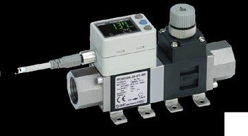


8 Circulating Fluid Temperature Controller Thermo-chiller Standard Type Series HRS090 Circulating Fluid/Facility Water Line Equipment Circulating Fluid Line Terminal block Power supply (24 VDC) available Circulating fluid return port Y-strainer Pressure Switch Bypass valve Valve Flow Switch Fittings and Tubing User's equipment Circulating fluid outlet Power supply (24 VDC) available Terminal block Facility Water Line (Water-cooled) Facility water outlet Facility water inlet Pressure Switch Flow Switch User's equipment Manage pressure and flow rate: digital display makes these aspects visible Flow Switch: Monitors flow rate and temperature of the circulating fluid. 3-Color Display Digital Flow Switch for Water PF3W 3-Color Display Electromagnetic Type Digital Flow Switch LFE Refer to the WEB catalog or the Best Pneumatics No. 6 for details. Digital Flow Switch for Deionized Water and Chemical Liquids PF2D 4-Channel Flow Monitor PF2 200 Integrated flow adjustment valve and temperature sensor PVC Piping Pressure Switch: Monitors pressure of the circulating fluid. 2-Color Display High-Precision Digital Pressure Switch ISE80 Refer to the WEB catalog or the Best Pneumatics No. 6 for details. Pressure Sensor for General Fluids PSE56 Pressure Sensor Controller PSE200,300 Fittings and Tubing Refer to the WEB catalog or the Best Pneumatics No. 6 for details. S Coupler KK S Coupler/Stainless Steel (Stainless Steel 304) KKA Tubing T Metal One-touch Fittings KQB2 Stainless Steel 316 One-touch Fittings KQG2 Series T TU TH TD TL TLM Material Nylon Polyurethane FEP (Fluoropolymer) Modified PTFE (Soft fluoropolymer) Super PFA PFA Stainless Steel 316 Insert Fittings KFG2 Fluoropolymer Fittings LQ 7
9 CONTENTS Series HRS090 Standard Type Thermo-chiller Series HRS090 How to Order/Specifications Air-cooled 200 V/400 V Page 9 Water-cooled 200 V/400 V Page 10 Cooling Capacity Page 11 Pump Capacity Page 11 Dimensions Page 12 Operation Display Panel Page 13 List of Function Page 13 Alarm Page 13 Communication Function Page 14 POptions With Earth Leakage Breaker Page 15 With Automatic Fluid Fill Function Page 15 Applicable to Deionized Water Piping Page 15 P Optional Accessories qpiping Conversion Fitting Page 16 wbypass Piping Set Page 16 eelectric Conductivity Control Set Page 17 rparticle Filter Set Page 17 tfilter for Circulating Fluid Fill Port Page 18 y Drain Pan Set (With Water Leakage Sensor) Page 18 P Cooling Capacity Calculation Required Cooling Capacity Calculation Page 19 Precautions on Cooling Capacity Calculation Page 20 Circulating Fluid Typical Physical Property Values Page 20 Specific Product Precautions Page 21 8 A
10 Thermo-chiller Standard Type Air-cooled 200 V/400 V Type Series HRS090 (Only 400 VAC type) RoHS HRS 090 A How to Order 20 Nil F N Cooling capacity kw A Cooling method Air-cooled refrigeration Pipe thread type Rc G (with Rc-G conversion fitting) NPT (with Rc-NPT conversion fitting) Power supply Option Nil None B Note) With earth leakage breaker J With automatic fluid fill function M Applicable to deionized water piping OWhen multiple options are combined, indicate symbols in alphabetical order. Note) 200 V type only. 400 V type is provided with an earth leakage breaker as standard phase 200 VAC (50 Hz) 3-phase 200 to 230 VAC (60 Hz) 40 3-phase 380 to 415 VAC (50/60 Hz) Specifications Model HRS090-Al-20-l HRS090-Al-40-l Cooling method Air-cooled refrigeration Refrigerant R410A (HFC) Control method PID control Ambient temperature 1 C 5 to 45 Circulating fluid 2 Tap water, 15% ethylene glycol aqueous solution, Deionized water Set temperature range 1 C 5 to 35 Cooling capacity 50/60 Hz 3 kw 8.0/9.0 Heating capacity 50/60 Hz 4 kw 1.7/2.2 Temperature stability 5 C ±0.5 Rated flow 50/60 Hz (Outlet) Pump L/min 29/45 Maximum flow rate 50/60 Hz L/min 55/68 capacity Maximum pump head m 50 Minimum operating flow rate 50/60 Hz 7 L/min 29/45 Tank capacity L 18 Circulating fluid outlet, circulating fluid return port Rc1 (Symbol F: G1, Symbol N: NPT1) Tank drain port Rc1/4 (Symbol F: G1/4, Symbol N: NPT1/4) Fluid contact material Stainless steel, Copper (Heat exchanger brazing), Brass, Bronze, PTFE, FKM, EPDM, PVC, NBR, POM, PE, PP, Carbon, Ceramic Power supply 3-phase 200 VAC (50 Hz), 3-phase 200 to 230 VAC (60 Hz) 3-phase 380 to 415 VAC (50/60 Hz) Allowable voltage range ±10% (No continuous voltage fluctuation) Allowable voltage range ±10% (No continuous voltage fluctuation) Applicable earth leakage Rated current A breaker (Standard) Sensitivity of leak current ma 30 Rated operating current 50/60 Hz 5 A 16/18 8.4/9.1 Rated power consumption 50/60 Hz 5 kw (kva) 4.3/5.4 (5.5/6.0) 4.4/5.6 (5.8/6.3) Noise level (Front 1 m/height 1 m) 5 db (A) Alarm code list stickers 2 pcs. (English 1 pc./japanese 1 pc.), Accessories Operation Manual (for installation/operation) 2 pcs. (English 1 pc./japanese 1 pc.), Y-strainer (40 meshes) 25A, Barrel nipple 25A, Anchor bolt fixing brackets 2 pcs. (including four M10 bolts) 8 Weight (dry state) kg Approx Use a 15% ethylene glycol aqueous solution if operating in a place where the ambient temperature and/or circulating fluid temperature is 10 C or less. 2 Use fluid in condition below as the circulating fluid. Tap water: Standard of The Japan Refrigeration And Air Conditioning Industry Association (JRA GL ) 15% ethylene glycol aqueous solution: diluted by tap water in condition above without any additives such as antiseptics. Deionized water: Electric conductivity 1 ms/cm or higher (Electric resistivity 1 MW cm or lower) 3 q Ambient temperature: 32 C, w Circulating fluid: Tap water, e Circulating fluid temperature: 20 C, r Circulating fluid flow rate: Rated flow, t Power supply: 200/400 VAC 4 q Ambient temperature: 32 C, w Circulating fluid: Tap water, e Circulating fluid flow rate: Rated flow, r Power supply: 200/400 VAC 5 q Ambient temperature: 32 C, w Circulating fluid: Tap water, e Circulating fluid temperature: 20 C, r Load: Same as the cooling capacity, t Circulating fluid flow rate: Rated flow, y Power supply: 200/400 VAC, u Piping length: Shortest 6 When circulating fluid outlet port pressure = 0.5 MPa. 7 Fluid flow rate to maintain the cooling capacity and to keep the circulating fluid discharge pressure to 0.5 MPa or less. If the actual flow rate is lower than this, install a bypass piping. 8 The anchor bolt fixing brackets (including four M10 bolts) are used for fixing to wooden skids when packaging the thermo-chiller. No anchor bolt is included. Circulating fluid system Electrical system 9
 NPT (with Rc-NPT conversion fitting) W Cooling method Water-cooled refrigeration 20 Power supply 20 3-phase 200 VAC (50 Hz) 3-phase 200 to 230 VAC (60 Hz) 40 3-phase 380 to")
11 Thermo-chiller Standard Type Water-cooled 200 V/400 V Type Series HRS090 (Only 400 VAC type) RoHS How to Order Nil F N Cooling capacity kw Specifications HRS 090 W Pipe thread type Rc G (with Rc-G conversion fitting) NPT (with Rc-NPT conversion fitting) W Cooling method Water-cooled refrigeration 20 Power supply 20 3-phase 200 VAC (50 Hz) 3-phase 200 to 230 VAC (60 Hz) 40 3-phase 380 to 415 VAC (50/60 Hz) Option Nil None B Note) With earth leakage breaker J With automatic fluid fill function M Applicable to deionized water piping OWhen multiple options are combined, indicate symbols in alphabetical order. Note) 200 V type only. 400 V type is provided with an earth leakage breaker as standard. Model HRS090-Wl-20-l HRS090-Wl-40-l Cooling method Water-cooled refrigeration Refrigerant R410A (HFC) Control method PID control Ambient temperature 1 C 5 to 45 Circulating fluid 2 Tap water, 15% ethylene glycol aqueous solution, Deionized water Set temperature range 1 C 5 to 35 Cooling capacity 50/60 Hz 3 kw 9.0/10.5 Heating capacity 50/60 Hz 4 kw 1.7/2.2 Temperature stability 5 C ±0.5 Rated flow 50/60 Hz (Outlet) Pump L/min 29/45 Maximum flow rate 50/60 Hz L/min 55/68 capacity Maximum pump head m 50 Minimum operating flow rate 50/60 Hz 7 L/min 29/45 Tank capacity L 18 Circulating fluid outlet, circulating fluid return port Rc1 (Symbol F: G1, Symbol N: NPT1) Tank drain port Rc1/4 (Symbol F: G1/4, Symbol N: NPT1/4) Fluid contact material Stainless steel, Copper (Heat exchanger brazing), Brass, Bronze, PTFE, FKM, EPDM, PVC, NBR, POM, PE, PP, Carbon, Ceramic Temperature range C 5 to 40 Pressure range MPa 0.3 to 0.5 Required flow 50/60 Hz L/min 25/25 Facility water pressure differential MPa 0.3 or more Facility water inlet/outlet Rc1/2 (Symbol F: G1/2, Symbol N: NPT1/2) Fluid contact material Stainless steel, Copper (Heat exchanger brazing), Bronze, Brass PTFE, NBR, EPDM Power supply 3-phase 200 VAC (50 Hz), 3-phase 200 to 230 VAC (60 Hz) 3-phase 380 to 415 VAC (50/60 Hz) Allowable voltage range ±10% (No continuous voltage fluctuation) Allowable voltage range ±10% (No continuous voltage fluctuation) Applicable earth Rated current A leakage breaker 8 Sensitivity of leak current ma 30 Rated operating current 50/60 Hz 5 A 13/14 6.4/6.7 Rated power consumption 50/60 Hz 5 kw (kva) 3.3/4.2 (4.4/4.9) 3.4/4.2 (4.4/4.7) Noise level (Front 1 m/height 1 m) 5 db (A) 65 Alarm code list stickers 2 pcs. (English 1 pc./japanese 1 pc.), Accessories Operation Manual (for installation/operation) 2 pcs. (English 1 pc./japanese 1 pc.), Y-strainer (40 meshes) 25A, Barrel nipple 25A, Anchor bolt fixing brackets 2 pcs. (including four M10 bolts) 9 Weight (dry state) kg Approx Use a 15% ethylene glycol aqueous solution if operating in a place where the ambient temperature and/or circulating fluid temperature is 10 C or less. Also, when there is a possibility of the facility water being frozen, make sure to discharge all the facility water from the facility water circuit. 2 Use fluid in condition below as the circulating fluid. Also, when there is a possibility of the facility water being frozen, make sure to discharge all the facility water from the facility water circuit. Tap water: Standard of The Japan Refrigeration And Air Conditioning Industry Association (JRA GL ) 15% ethylene glycol aqueous solution: diluted by tap water in condition above without any additives such as antiseptics. Deionized water: Electric conductivity 1 ms/cm or higher (Electric resistivity 1 MW cm or lower) 3 q Facility water temperature: 32 C, w Circulating fluid: Tap water, e Circulating fluid temperature: 20 C, r Circulating fluid flow rate: Rated flow, t Power supply: 200/400 VAC 4 q Facility water temperature: 32 C, w Circulating fluid: Tap water, e Circulating fluid flow rate: Rated flow, r Power supply: 200/400 VAC 5 q Facility water temperature: 32 C, w Circulating fluid: Tap water, e Circulating fluid temperature: 20 C, r Load: Same as the cooling capacity, t Circulating fluid flow rate: Rated flow, y Power supply: 200/400 VAC, u Piping length: Shortest 6 When circulating fluid outlet port pressure = 0.5 MPa. 7 Fluid flow rate to maintain the cooling capacity and to keep the circulating fluid discharge pressure to 0.5 MPa or less. If the actual flow rate is lower than this, install a bypass piping. 8 To be prepared by user. A specified earth leakage breaker is installed for option B [With earth leakage breaker]. 9 The anchor bolt fixing brackets (including four M10 bolts) are used for fixing to wooden skids when packaging the thermo-chiller. No anchor bolt is included. Circulating fluid system Facility water system Electrical system 10
12 Series HRS090 Standard Type Cooling Capacity HRS090-A-20/40 (50 Hz) 12 HRS090-A-20/40 (60 Hz) 12 Cooling capacity [kw] Ambient temperature 32 C Ambient temperature 40 C Ambient temperature 45 C Cooling capacity [kw] Ambient temperature 32 C Ambient temperature 40 C Ambient temperature 45 C Circulating fluid temperature [ C] HRS090-W-20/40 (50 Hz) Circulating fluid temperature [ C] HRS090-W-20/40 (60 Hz) 14 Cooling capacity [kw] Facility water temperature 32 C Facility water temperature 40 C Cooling capacity [kw] Facility water temperature 32 C Facility water temperature 40 C Circulating fluid temperature [ C] Circulating fluid temperature [ C] Pump Capacity HRS090-A-20/40 HRS090-W-20/40 Circulating fluid pressure [MPa] Usable range (50 Hz) Usable range (60 Hz) Circulating fluid outlet (50 Hz) Circulating fluid outlet (60 Hz) Circulating fluid 0 return port Circulating fluid flow rate [L/min] Pump head [m] 11
13 Thermo-chiller Standard Type Series HRS090 Dimensions HRS090-m-20/40 Ventilation air outlet Ventilation air inlet Circulating fluid fill port lid Operation display panel 377 Fluid level indicator 970 Serial communication (RS-485/RS-232C) connector D-sub female receptacle Contact input/output communication connector Signal cable entry (Hole 40) (Grommet with membrane) Option B Note 2) [With earth leakage breaker] Handle (Same for the opposite side) Handle Power terminal Circulating fluid return port Rc1 Circulating fluid outlet Rc Note 1) Dustproof filter Power cable entry (Hole 40) (Grommet with membrane) Caster (unfixed) with locking lever Anchor bolt fixing bracket (Accessory) M10 bolt (Accessory) A Note 1) The water-cooled type is not equipped with a dustproof filter. Note 2) 400 V type is provided with an earth leakage breaker -B as standard. Caster (unfixed) Drain port Rc1/4 (Valve stopper) Anchor bolt fixing position 1015 (Dimension of anchor bolt fixing bracket) 4 x ø (377) (Thermo-chiller dimension) Facility water outlet Rc1/2 (970) (Thermo-chiller dimension) View A 28 Facility water inlet Rc1/ Accessory: Y-strainer mounting view Mount it by yourself on the circulating fluid return port. For water-cooled type 153 Flow direction Circulating fluid return port Rc1 Barrel nipple 25A Y-strainer (Accessory) Barrel nipple (25A) (Accessory) Y-strainer (40 mesh) 25A 12
14 Series HRS090 Standard Type Operation Display Panel The basic operation of this unit is controlled through the operation display panel on the front of the product. ew q r t y u i o!0!5!1!2!3!6!4 No. Description Function Displays the circulating fluid current discharge temperature Digital display PV and pressure and alarm codes and other menu items (codes). q (7 segment, 4 digits) Displays the circulating fluid discharge temperature SV and the set values of other menus. Equipped with a unit conversion function. Displays the w [ C] [ F] lamp unit of displayed temperature (default setting: C). [MPa] [PSI] Equipped with a unit conversion function. Displays the e lamp unit of displayed pressure (default setting: MPa). r [REMOTE] Enables remote operation (star t and stop) by lamp communication. Lights up during remote operation. Lights up when the product is started, and goes off when t [RUN] lamp it is stopped. Flashes during stand-by for stop or antifreezing function, or independent operation of the pump. y [ALARM] lamp Flashes with buzzer when alarm occurs. u [ ] lamp Lights up when the surface of the fluid level indicator falls below the L level. Equipped with a timer for start and stop. Lights up i [ ] lamp when this function is operated. Equipped with a power failure auto-restart function, which o [ ] lamp restarts the product automatically after stopped due to a power failure. Lights up when this function is operated.!0 [RUN/STOP] key Makes the product start or stop. Shifts the main menu (display screen of circulating fluid discharge temperature!1 [MENU] key and pressure) and other menus (for monitoring and entry of set values).!2 [SEL] key Changes the item in menu and enters the set value.!3 [ ] key Decreases the set value.!4 [ ] key Increases the set value. Press the [MENU] and [RUN/STOP] keys simultaneously. The pump starts!5 [PUMP] key running independently to make the product ready for start-up (release the air).!6 [RESET] key Press the [ ] and [ ] keys simultaneously. The alarm buzzer is stopped and the [ALARM] lamp is reset. List of Function No. Function Outline 1 Main display Displays the current and set temperature of the circulating fluid, discharge pressure of the circulating fluid. Changes the circulating fluid set temperature. 2 Alarm display menu Indicates alarm number when an alarm occurs. 3 Inspection monitor menu Product temperature, pressure and accumulated operating time can be checked as daily inspection. Use these for daily inspection. 4 Key-lock Keys can be locked so that set values cannot be changed by operator error. 5 Timer for operation start/stop Timer is used to set the operation start/stop. 6 Signal for the completion of preparation 7 Offset function Reset after 8 power failure Key click 9 sound setting 10 Changing temp. unit 11 Changing pressure unit 12 Data reset 13 Accumulation time reset 14 Anti-freezing function 15 Warming-up function Alarm buzzer 16 sound setting 17 Alarm customizing 18 Communication A signal is output when the circulating fluid temperature reaches the set temperature, when using contact input/output and serial communication. Use this function when there is a temperature offset between the discharge temperature of the thermo-chiller and user s equipment. Start operation automatically after the power supply is turned on. Operation panel key sound can be set on/off. Temperature unit can be changed. Centigrade ( C) Fahrenheit ( F) Pressure unit can be changed. MPa PSI Functions can be reset to the default settings (settings when shipped from the factory). Reset function when the pump, the fan or the compressor is replaced. Reset the accumulated time here. Circulating fluid is protected from freezing during winter or at night. Set beforehand if there is a risk of freezing. When circulating fluid temperature rising time at starting needs shortening during winter or at night, set beforehand. Alarm sound can be set to on/off. Operation during alarm condition and threshold values can be changed depending on the alarm type. This function is used for contact input/output or serial communication. Alarm This unit has alarms as standard, and displays each of them by its alarm code on the PV screen with the [ALARM] lamp ([LOW LEVEL] lamp) lit up on the operation display panel. The alarm can be read out through communication. Code AL01 AL02 AL03 AL04 AL05 AL06 AL07 AL08 AL09 AL10 AL11 AL12 AL13 AL15 AL16 Alarm message Low level in tank High circulating fluid discharge temp. Circulating fluid discharge temp. rise Circulating fluid discharge temp. drop High circulating fluid return temp. High circulating fluid discharge pressure Abnormal pump operation Circulating fluid discharge pressure rise Circulating fluid discharge pressure drop High compressor intake temp. Low compressor intake temp. Low super heat temp. High compressor discharge pressure Refrigeration circuit pressure (high pressure side) drop Refrigeration circuit pressure (low pressure side) rise Code AL17 AL18 AL19 AL20 AL21 AL22 AL23 AL24 AL25 AL26 AL27 AL28 AL29 AL30 AL31 Alarm message Refrigeration circuit pressure (low pressure side) drop Compressor running failure Communication error Memory error DC line fuse cut Circulating fluid discharge temp. sensor failure Circulating fluid return temp. sensor failure Compressor intake temp. sensor failure Circulating fluid discharge pressure sensor failure Compressor discharge pressure sensor failure Compressor intake pressure sensor failure Pump maintenance Fan maintenance Compressor maintenance Contact input 1 signal detection Code Alarm message AL32 Contact input 2 signal detection AL37 Compressor discharge temp. sensor failure AL38 Compressor discharge temp. rise AL40 Dustproof filter maintenance Note) AL41 Power stoppage AL42 Compressor waiting AL43 Fan failure Note) AL45 Compressor over current AL47 Pump over current AL50 Incorrect phase error AL51 Phase board over current Note) Does not occur on the product of water-cooled refrigeration type. * For details, read the Operation Manual. 13 For details, refer to the Operation Manual. Please download it via our website,
15 Thermo-chiller Standard Type Series HRS090 Communication Function Contact Input/Output Item Connector type Insulation method Rated input voltage Input signal Operating voltage range Rated input current Input impedance Rated load voltage Contact output Maximum load current signal Minimum load current Output voltage Specifications M3 terminal block Photocoupler 24 VDC 21.6 to 26.4 VDC 5 ma TYP 4.7 kw 48 VAC or less/30 VDC or less 500 ma AC/DC (resistance load) 5 VDC 10 ma 24 VDC ±10% 500 ma MAX (No inductive load) To the thermo-chiller User s equipment side 24 VDC VDC output 5 (500 ma MAX) VCOM VCOM output Circuit diagram 4.7 kω 1 kω 12 4 Signal description Contact input signal 2 Default setting Internal circuit 4.7 kω 1 kω Contact input signal 1 Contact output signal 3 Contact output signal 2 Run/stop signal input Alarm status signal output Remote status signal output 8 0 Contact output signal 1 Operation status signal output * The pin numbers and output signals can be set by user. For details, refer to the Operation Manual for communication. Serial Communication The serial communication (RS-485/RS-232C) enables the following items to be written and read out. For details, refer to the Operation Manual for communication. Writing Run/Stop Circulating fluid temperature setting (SV) Readout Circulating fluid present temperature Circulating fluid discharge pressure Status information Alarm occurrence information Item Specifications Connector type D-sub 9-pin, Female connector Protocol Modicon Modbus compliant/simple communication protocol Standards EIA standard RS-485 EIA standard RS-232C To the thermo-chiller User s equipment side To the thermo-chiller User s equipment side Circuit diagram Internal circuit SD+ SG SD Internal circuit RD SD SG * The terminal resistance of RS-485 (120 W) can be switched by the operation display panel. For details, refer to the Operation Manual for communication. Do not connect other than in the way shown above, as it can result in failure. Please download the Operation Manual via our website, 14
16 Series HRS090 Options Note) Select the option when ordering the thermo-chiller because the option cannot be added after purchasing the unit. B HRS090 Option symbol With Earth Leakage Breaker 20 B A leakage breaker is built in to automatically stop the supply power when it has short-circuit, over current or electrical leakage. (For models with power supply specification -40, it is not necessary to select this option because an earth leakage breaker is equipped as standard.) Applicable model With earth leakage breaker Rated current [A] * 400 V type is equipped as standard. Sensitivity of leak current [ma] HRS090-ll-20-B Short circuit display method Mechanical button Earth leakage breaker J HRS090 Option symbol With Automatic Fluid Fill Function J By installing this at the automatic fluid fill port, the circulating fluid can be automatically supplied to the product using a built-in solenoid valve for filling fluid while the circulating fluid is decreasing. Applicable model Fluid fill method With automatic fluid fill function HRS090-ll-l-J Built-in solenoid valve for automatic fluid filling Fluid fill pressure [MPa] 0.2 to 0.5 Feed water temperature [ C] 5 to 40 Automatic fluid fill port (Rc3/8) Overflow port (Rc3/4) M Option symbol Applicable to Deionized Water Piping HRS090 M Applicable to deionized water piping Contact material of the circulating fluid circuit is made from non-copper materials. Applicable model HRS090-ll-l-M Contact material Stainless steel (including heat exchanger brazing), SiC, Carbon, for circulating fluid PP, PE, POM, FKM, NBR, EPDM, PVC, PTFE No change in external dimensions. 15
17 Series HRS090 Optional Accessories q Piping Conversion Fitting This is a fitting to change the port from Rc to G or NPT. C irculating fluid outlet, Circulating fluid return port Rc1 NPT1 or G1 Drain port Rc1/4 NPT1/4 or G1/4 (It is not necessary to purchase this when pipe thread type F or N is selected in How to Order since it is included in the product.) Part no. HRS-EP018 HRS-EP019 Contents NPT thread conversion fitting set G thread conversion fitting set Applicable model Part no. HRS090-A-20/40 HRS-EP022 HRS-EP023 Contents NPT thread conversion fitting set G thread conversion fitting set Applicable model HRS090-W-20/40 Conversion fitting for circulating fluid Conversion fitting for circulating fluid Material: Stainless steel Material: Stainless steel 2 pcs./set 2 pcs./set Conversion fitting for drain outlet Conversion fitting for drain outlet Material: Stainless steel Material: Stainless steel 1 pc. 1 pc. Conversion fitting for facility water Material: Stainless steel When option J (With automatic fluid fill function) is included, use the following part numbers. 2 pcs./set Automatic fluid fill port Rc3/8 R NPT3/8 or G3/8 Overflow port Rc3/4 R NPT3/4 or G3/4 The conversion fittings for circulating fluid outlet/return port, drain port, facility water inlet/outlet (for water-cooled refrigeration) are also included. Part no. HRS-EP020 HRS-EP021 Contents NPT thread conversion fitting set G thread conversion fitting set Applicable model Part no. HRS090-A-20/40-J HRS-EP024 HRS-EP025 Contents NPT thread conversion fitting set G thread conversion fitting set Applicable model HRS090-W-20/40-J w Bypass Piping Set When the circulating fluid goes below the minimum operating flow rate (as shown below), cooling capacity will be reduced and the temperature stability will be badly affected. Use the bypass piping set to ensure a circulating fluid flow rate of the minimum operating flow rate or more. Part no. Applicable model Minimum operating flow rate (50/60 Hz) [L/min] HRS-BP005 HRS090-ll-20/40 29/45 To circulating fluid return port r t r e q To circulating fluid outlet r t r w Parts List No. u y q Description Hose (I.D.: 15 mm, Length: 700 mm) w Outlet piping assembly (With globe valve) e Return piping assembly r Barrel nipple (Size: 1 inch) (2 pcs.) t Union (Size: 1 inch) (2 pcs.) y Sealant tape u Operation Manual 16 A
18 Series HRS090 e Electric Conductivity Control Set The set indicates and controls the electric conductivity of the circulating fluid. Refer to the Operation Manual for details. Part no. HRS-DI007 Measurement range of electric conductivity Applicable model HRS090-ll-20/ to 48.0 ms/cm Set range of electric conductivity target 5.0 to 45.0 ms/cm Set range of electric conductivity hysteresis Operating temperature range (Circulating fluid temperature) Power consumption 2.0 to 10.0 ms/cm 5 to 60 C 400 ma or less To mounting thread hole To circulating fluid return port t y o i (263) (Height to the bottom of the resin filter vessel) (314) (Flying-out size) Circulating fluid return port Circulating fluid outlet!0q e w To circulating fluid outlet o r u Parts List No. q w e r t y u i o!0 Description DI filter vessel (resin) Mounting bracket DI filter inlet tube DI filter outlet tube Tapping screw (4 pcs.) Mounting screw (4 pcs.) DI control piping assembly DI sensor assembly Nipple (2 pcs.) DI filter cartridge (Part no.: HRS-DF001) r Particle Filter Set Removes foreign matter in the circulating fluid. This set cannot be directly connected to the thermo-chiller. Install it in the user s piping system. Refer to the Operation Manual for details. Particle Filter Set HRS PF005 Accessory Symbol Accessory Nil None H With handle H Fluid Max. operating pressure Tap water 0.65 MPa Operating temperature range 5 to 35 C Nominal filtration accuracy Installation environment 5 μm Indoors Parts List No. Description Material Q'ty Note q Body PC, PP 1 w Element PP 1 e Extension piece Stainless steel 2 Conversion from NPT to Rc r Handle 1 When -H is selected t Sealant tape PTFE 1 Replacement Element HRS PF006 e Rc1 NPT1 NPT1 (256) e Rc1 w (343) q r t 17
19 Optional Accessories Series HRS090 t Filter for Circulating Fluid Fill Port Prevents foreign matter from entering the tank when supplying the circulating fluid. Can be used just by fitting into the circulating fluid fill port. Filter for circulating fluid fill port HRS-PF007 Material Stainless steel 304, Stainless steel 316 Mesh size 200 Tank lid Filter for circulating fluid fill port After supplying the circulating fluid, the tank lid can be closed with the filter mounted. Circulating fluid fill port y Drain Pan Set (With Water Leakage Sensor) Drain pan for the thermo-chiller. Liquid leakage from the thermo-chiller can be detected by mounting the attached water leakage sensor. Align the drain pan with the hole in the bottom of the thermo-chiller for installation. Part no. HRS-WL003 Applicable model HRS090-mm-20/40 tre w q Parts List No. Description q Drain pan w Water leakage sensor e Extension cable r Binding band (4 pcs.) t Cable fixture (4 pcs.) 18 A
20 Series HRS090 Cooling Capacity Calculation Required Cooling Capacity Calculation Example 1: When the heat generation amount in the user s equipment is known. The heat generation amount can be determined based on the power consumption or output of the heat generating area i.e. the area requiring cooling within the user s equipment.* q Derive the heat generation amount from the power consumption. Power consumption P: 7 [kw] Q = P = 7 [kw] Cooling capacity = Considering a safety factor of 20%, 7 [kw] x 1.2 = 8.4 [kw] V: Power supply voltage I: Current P Power consumption Q: Heat generation amount User s equipment w Derive the heat generation amount from the power supply output. Power supply output VI: 8.8 [kva] Q = P = V x I x Power factor In this example, using a power factor of 0.85: = 8.8 [kva] x 0.85 = 7.5 [kw] Cooling capacity = Considering a safety factor of 20%, 7.5 [kw] x 1.2 = 9.0 [kw] e Derive the heat generation amount from the output. Output (shaft power etc.) W: 13 [kw] W Q = P = Efficiency In this example, using an efficiency of 0.7: 5.1 = = 7.3 [kw] 0.7 Cooling capacity = Considering a safety factor of 20%, 7.3 [kw] x 1.2 = 8.8 [kw] * The above examples calculate the heat generation amount based on the power consumption. The actual heat generation amount may differ due to the structure of the user s equipment. Be sure to check it carefully. Example 2: When the heat generation amount in the user s equipment is not known. Obtain the temperature difference between inlet and outlet by circulating the circulating fluid inside the user s equipment. Heat generation amount by user s equipment Q : Unknown [W] ([J/s]) Circulating fluid : Tap water * Circulating fluid mass flow rate qm : (= ρ x qv 60) [kg/s] Circulating fluid density ρ : 1 [kg/l] Circulating fluid (volume) flow rate qv : 35 [L/min] Circulating fluid specific heat C : x 10 3 [J/(kg K)] Circulating fluid outlet temperature T1 : 293 [K] (20 [ C]) Circulating fluid return temperature T2 : 296 [K] (23 [ C]) Circulating fluid temperature difference it : 3 [K] (= T2 T1) Conversion factor: minutes to seconds (SI units) : 60 [s/min] 19 * Refer to page 11 for the typical physical property value of tap water or other circulating fluids. Q = qm x C x (T2 T1) ρ x qv x C x it 1 x 35 x x 10 3 x 3.0 = = = 7325 [J/s] 7325 [W] = 7.3 [kw] Cooling capacity = Considering a safety factor of 20%, 7.3 [kw] x 1.2 = 8.8 [kw] Thermo-chiller HRS090-A T1: Outlet temperature T2: Return temperature T = T2 T1 qv: Circulating fluid flow rate Q: Heat generation amount User s equipment Example of conventional measurement units (Reference) Heat generation amount by user s equipment Q : Unknown [cal/h] [W] Circulating fluid : Tap water * Circulating fluid weight flow rate qm : (= ρ x qv x 60) [kgf/h] Circulating fluid weight volume ratio : 1 [kgf/l] Circulating fluid (volume) flow rate qv : 35 [L/min] Circulating fluid specific heat C : 1.0 x 10 3 [cal/(kgf C)] Circulating fluid outlet temperature T1 : 20 [ C] Circulating fluid return temperature T2 : 23 [ C] Circulating fluid temperature difference it : 3 [ C] (= T2 T1) Conversion factor: hours to minutes : 60 [min/h] Conversion factor: kcal/h to kw : 860 [(cal/h)/w] Q = = = qm x C x (T2 T1) 860 x qv x 60 x C x it x 35 x 60 x 1.0 x 10 3 x [W] = 7.3 [kw] Cooling capacity = Considering a safety factor of 20%, 7.3 [kw] x 1.2 = 8.8 [kw]
21 Cooling Capacity Calculation Series HRS090 Required Cooling Capacity Calculation Example 3: When there is no heat generation, and when cooling the object below a certain temperature and period of time. Heat quantity by cooled substance (per unit time) Q : Unknown [W] ([J/s]) Cooled substance : Water Cooled substance mass m : (= ρ x V) [kg] Cooled substance density ρ : 1 [kg/l] Cooled substance total volume V : 150 [L] Cooled substance specific heat C : x 10 3 [J/(kg K)] Cooled substance temperature when cooling begins T0 : 303 [K] (30 [ C]) Cooled substance temperature after t hour Tt : 293 [K] (20 [ C]) Cooling temperature difference it : 10 [K] (= T0 Tt) Cooling time it : 900 [s] (= 15 [min]) * Refer to the following for the typical physical property values by circulating fluid. m x C x (T0 Tt) ρ x V x C x it Q = = it it 1 x 150 x x 10 3 x 10 = = 6977 [J/s] 7.0 [kw] 900 Cooling capacity = Considering a safety factor of 20%, Thermo-chiller 7.0 [kw] x 1.2 = 8.4 [kw] Q x t: Heat capacity [kj] 20 C HRS090-A Water bath V After 15 minutes, cool 32 C down to 20 C. Precautions on Cooling Capacity Calculation Example of conventional measurement units (Reference) Heat quantity by cooled substance (per unit time) Q : Unknown [cal/h] [W] Cooled substance : Water Cooled substance weight m : (= ρ x V) [kgf] Cooled substance weight volume ratio : 1 [kgf/l] Cooled substance total volume V : 150 [L] Cooled substance specific heat C : 1.0 x 10 3 [cal/(kgf C)] Cooled substance temperature when cooling begins T0 : 30 [ C] Cooled substance temperature after t hour Tt : 20 [ C] Cooling temperature difference it : 10 [ C] (= T0 Tt) Cooling time it : 15 [min] Conversion factor: hours to minutes : 60 [min/h] Conversion factor: kcal/h to kw : 860 [(cal/h)/w] m x C x (T0 Tt) Q = = it x x 150 x 60 x 1.0 x 10 = 3 x x [W] = 7.0 [kw] x V x 60 x C x it it x 860 Cooling capacity = Considering a safety factor of 20%, 7.0 [kw] x 1.2 = 8.4 [kw] Note) This is the calculated value by changing the fluid temperature only. Thus, it varies substantially depending on the water bath or piping shape. 1. Heating capacity When the circulating fluid temperature is set above room temperature, it needs to be heated by the thermo-chiller. The heating capacity depends on the circulating fluid temperature. Consider the radiation rate and heat capacity of the user s equipment and check beforehand if the required heating capacity is provided. 2. Pump capacity <Circulating fluid flow rate> Circulating fluid flow rate varies depending on the circulating fluid discharge pressure. Consider the installation height difference between the thermo-chiller and the user s equipment, and the piping resistance such as circulating fluid pipings, or piping size, or piping curves in the machine. Check beforehand if the required flow is achieved, using the pump capacity curves. <Circulating fluid discharge pressure> Circulating fluid discharge pressure has the possibility to increase up to the maximum pressure in the pump capacity curves. Check beforehand if the circulating fluid pipings or circulating fluid circuit of the user s equipment are fully durable against this pressure. Circulating Fluid Typical Physical Property Values 1. This catalog uses the following values for density and specific heat in calculating the required cooling capacity. Density ρ: 1 [kg/l] (or, using conventional unit system, weight volume ratio = 1 [kgf/l] ) Specific heat C: 4.19 x 10 3 [J/(kg K)] (or, using conventional unit system, 1 x 10 3 [cal/(kgf C)]) 2. Values for density and specific heat change slightly according to temperature shown below. Use this as a reference. Water Physical property Density ρ value Temperature [kg/l] Specific heat C [J/(kg K)] Conventional unit system Weight volume ratio [kgf/l] Specific heat C [cal/(kgf C)] 5 C x x C x x C x x C x x C x x C x x C x x C x x % Ethylene Glycol Aqueous Solution Physical property Density ρ value Temperature [kg/l] Specific heat C [J/(kg K)] Conventional unit system Weight volume ratio [kgf/l] Specific heat C [cal/(kgf C)] 5 C x x C x x C x x C x x C x x C x x C x x C x x 10 3 Note) The above shown are reference values. Contact circulating fluid supplier for details. 20
using heat exhausted by refrigerating circuit.
 Circulating Fluid Temperature Controller Thermo-chiller No heater required, circulating fluid is heated using heat exhausted by refrigerating circuit. Circulating fluid temperature [ F] Cooling capacity
±0.1 C. 40 kg. 47 kg. 69 kg 73 kg. With heating function. Convenient functions
 Circulating Fluid Temperature Controller Thermo-chiller Lightweight/Compact Temperature stability Standard Type ±.1 C New HRS5 New HRS6 (UL Standards) RoHS HRS12/18/24 New HRS3 Same width for all models:
RoHS HRG(C)005 (Existing model) (mm) 69 kg 5100 W
005 (Existing model) (mm) 69 kg 5100 W") New Circulating Fluid Temperature Controller Thermo-chiller (UL Standards) Compact Type RoHS HRG(C)5 (Existing model) Compact Space-saving HRS5 976 Ve 615 n tio 592 5 377 377 (mm) (mm) Lightweight 4 kg
New Circulating Fluid Temperature Controller Thermo-chiller (UL Standards) Compact Type RoHS HRG(C)5 (Existing model) Compact Space-saving HRS5 976 Ve 615 n tio 592 5 377 377 (mm) (mm) Lightweight 4 kg
Large energy saving by triple control!
 Circulating Fluid Temperature Controller Thermo-chiller Basic Type (Only 23 VAC type) RoHS Large energy saving by triple control!.8 kw.54 kw Power consumption 33% Energy saving * Under the conditions shown
Circulating Fluid Temperature Controller Refrigerated Thermo-cooler
 Circulating Fluid Temperature Controller Refrigerated Thermo-cooler Makes cooling water easily available, anytime, anywhere. Worldwide in voltage: Single phase 200 to 230 VAC, 50/60 Hz Compliant with standards:,
Large energy saving by triple control!
 Circulating Fluid Temperature Controller Thermo-chiller E Series Basic Type Large energy saving by triple control!.8 kw Without triple control.54 kw Triple control Cooling capacity 1.2, 1.6, 2.2 kw Power
Large energy saving by triple control!
 Circulating Fluid Temperature Controller Thermo-chiller Small Basic Type RoHS Large energy saving by triple control! Compressor Fan Valve Triple control.8 kw.54 kw Power consumption 33% Energy saving *
SEMI Standard S2-0703, S8-1103, F
 Circulating Fluid Temperature Controller Water-cooled Thermo-chiller Series Refrigerant-free and energy saving type using no compressor. Ideal for ordinary temperature and high temperature processes. Type
Type of Fluorinated fluids / Ethylene glycol aqueous solution / circulating fluid: Clear water, Deionized water Temperature range setting:
 Circulating Fluid Temperature Controller Refrigerated Thermo-chiller Series Type of Fluorinated fluids / Ethylene glycol aqueous solution / circulating fluid: Clear water, Deionized water Temperature range
Refrigerated Thermo-chiller
 Circulating Fluid Temperature Controller Refrigerated Thermo-chiller Series Type of Fluorinated fluids/ethylene glycol aqueous solution/ circulating fluid: Clear water, Deionized water Temperature range
Refrigerated Thermo-cooler
 Circulating Fluid Temperature Controller Refrigerated Thermo-cooler Series Makes cooling water easily available, anytime, anywhere. Cooling capacity (60 Hz): 9.5 kw/14.5 kw (Air-cooled refrigeration) 11.0
Chiller Lineup. Thermo-chiller. A chiller is used to control the temperature of circulating fluid and supply it to the heat source.
 A chiller is used to control the temperature of circulating fluid and supply it to the heat source. Thermo-cooler Series HRG General-purpose, economy type for machine tools, etc. Cooling capacity: 1 kw
Water-cooled Thermo-chiller
 temperature controller Water-cooled Thermo-chiller Refrigerant-free and energy saving type using no compressor. Ideal for ordinary temperature and high temperature processes. Circulating Fluorinated fluids
Water-cooled Thermo-chiller
 SEMATECH S2-93, S8-95 temperature controller Water-cooled Thermo-chiller Refrigerant-free and energy saving type using no compressor. Ideal for ordinary temperature and high temperature processes. types:
Water-cooled Thermo-chiller
 Circulating Fluid Temperature Controller Water-cooled Thermo-chiller SEMATECH S2-93, S8-95 SEMI Standard S2-73, S8-113, F47-2 Series Refrigerant-free and energy saving type using no compressor. Ideal for
Water-cooled Thermo-chiller
 Circulating Fluid Temperature Controller Water-cooled Thermo-chiller Series Refrigerant-free and energy saving type using no compressor. Ideal for ordinary temperature and high temperature processes. Type
Mountable in a 19-inch rack
 Peltier-Type Chiller/Thermo-con HECR Series Air-cooled Rack Mount Type (UL Standards) RoHS HRS Good space utilization Mountable in a 19-inch rack Saves space by mounting multiple equipment together in
0.1 c. R134a (HFC) Thermo-chiller. ( A device for circulating a fluid ) Series HRZ. with a constant temperature
 Thermo-chiller. ( A device for circulating a fluid ) Series HRZ. with a constant temperature") Circulating fluids type: Fluorinated fluids, Ethylene glycol aqueous solution / Clean water, Pure water Temperature 2 to 4 c 2 to 9 c 2 setting range: to 9 c Cooling capacity: 1 kw 2 kw 4 kw 8 kw to Max.15
Circulating fluids type: Fluorinated fluids, Ethylene glycol aqueous solution / Clean water, Pure water Temperature 2 to 4 c 2 to 9 c 2 setting range: to 9 c Cooling capacity: 1 kw 2 kw 4 kw 8 kw to Max.15
Can precisely control the temperature of a heat source or process fluid.
 Peltier-Type Chiller/Thermo-con Series Water-cooled HRS9 HRS Can precisely control the temperature of a heat source or process fluid. Water-cooled Added cooling capacity of 14 W and 32 W (watercooled),
Precisely control the temperature of the circulating fluid by using the Peltier device. Refrigerant-free and environmentally friendly.
 Peltier-type Chiller Thermo-con/Rack Mount Type Air-cooled Water-cooled The water-cooled type has been added. (8 W, 1.2 kw) Reduces the amount of exhaust heat by 9% Suppresses rises in the ambient temperature
Operation Manual Installation Operation
 HRX-OM-Q026 1 st edition: December 2012 Rev. L: Nov.2017 Operation Manual Installation Operation Original Instructions Thermo Chiller HRSH100-A -20- HRSH150-A -20- HRSH200-A -20- HRSH250-A -20- HRSH300-A
Operation Manual Installation Operation
 -B 1 st edition: Dec. 2010 3 rd edition: Feb. 2011 Operation Manual Installation Operation Air-Cooled refrigerated type HRS050-A -20- Thermo chiller Water-Cooled refrigerated type HRS050-W -20- Keep this
Added cooling capacity of 140 W. (air-cooled).
.") Peltier-Type Chiller/Thermo-con Series Air-cooled Water-cooled Can precisely control the temperature of a heat source or process fluid. Precisely control the temperature of the circulating fluid by using
Peltier-Type Chiller/Thermo-con Series Air-cooled Water-cooled Can precisely control the temperature of a heat source or process fluid. Precisely control the temperature of the circulating fluid by using
Operation Manual Installation Operation
 1 st edition: Aug. 2013 Rev.H: Nov. 2017 Operation Manual Installation Operation Air-Cooled refrigerated type HRS030-A -20- Original Instructions Thermo chiller Water-Cooled refrigerated type HRS030-W
A Chiller is equipment to control temperature of customers heating sources. Application Examples
 Control Equipment What s a Chiller? A Chiller is equipment to control temperature of customers heating sources. Chillers control, such as water, and circulate the to customers machine using a pump by controlling
HEB Series. Peltier-Type Thermoelectric Bath
 Peltier-Type Thermoelectric Bath HRS090 HRZD HRZ HRSE HRSH Environmentally friendly and refrigerant-free Heaterless Function to detect abnormal heating and temperature sensor errors comes standard. Light
Give yourself peace of mind
 Give yourself peace of mind Circulating Fluid Temperature Controller Thermo-Chiller Standard Type HRS Series Basic Type HRSE Series High-level Type HRSH Series Quick Overview Thermo-Chiller HRS/HRSE/HRSH
Operation Manual Installation Operation
 -G 1 st edition: Jul. 2009 8 th edition: Oct. 2010 Operation Manual Installation Operation Air-Cooled refrigerated type HRS012-A -10- HRS018-A -10- HRS012-A -20- HRS018-A -20- HRS024-A -20- Original Instructions
Added cooling capacity of 140 W. (air-cooled).
.") Peltier-Type Chiller Thermo-con Can precisely control the temperature of a heat source or process fluid. Precisely control the temperature of the circulating fluid by using the Peltier device. Generates
Peltier-Type Chiller Thermo-con Can precisely control the temperature of a heat source or process fluid. Precisely control the temperature of the circulating fluid by using the Peltier device. Generates
Added cooling capacity of 140 W and 320 W (watercooled), (air-cooled). Thermo-con. controlled to a constant temperature
, (air-cooled). Thermo-con. controlled to a constant temperature") Peltier-Type Chiller Thermo-con Air-cooled Water-cooled Series Can precisely control the temperature of a heat source or process fluid. Precisely control the temperature of the circulating fluid by using
Peltier-Type Chiller Thermo-con Air-cooled Water-cooled Series Can precisely control the temperature of a heat source or process fluid. Precisely control the temperature of the circulating fluid by using
Refrigerated Air Dryer
 Refrigerated Air Dryer Applicable for the high-temperature environments Ambient temperature : Max. 45 C Inlet air temperature : Max. 65 C Air flow capacity * IDF90-20, Dew point of 10 C, 60 Hz 16.4 m 3
% by up ctoond re-heater and
 Refrigerated Air Dryer 100FS/125FS/150FS Series Saves energy 76 % by up ctoond re-heater and Digital scroll compressor Stainless steel heat exchanger Ozone depletion potential ZERO refrigerant RoHS HAA
Refrigerated Air Dryer
 Refrigerated Air Dryer For Use in Europe, Asia and Oceania Applicable for the high-temperature environments Ambient temperature : Max. 45 C Inlet air temperature : Max. 65 C Air flow capacity * IDFA90-23,
Thermoelectric Bath. Series HEB
 Peltier-Type Thermoelectric Bath Accurately controls the temperature of liquid in the bath. Temperature stability: ±0.018 F Temperature distribution: ±0.036 F in the bath Environmentally friendly and refrigerant-free
Refrigerated Air Dryer
 Refrigerated Air Dryer For Use in Southeast Asia Applicable for the high-temperature environments of tropical regions Can be used in high-temperature environments Ambient temperature : Max. 45 C Inlet
Water Circulator (Chiller) & Cold Trap
 & Cold Trap") Yamato Scientific America Innovating Science for Over 125 Years Water Circulator (Chiller) & Cold Trap Contents Water Circulator (Chiller) Cold Trap CA Series Page Page 91 93 9 Water Circulator (Chiller)
Yamato Scientific America Innovating Science for Over 125 Years Water Circulator (Chiller) & Cold Trap Contents Water Circulator (Chiller) Cold Trap CA Series Page Page 91 93 9 Water Circulator (Chiller)
Operation Manual Installation Operation
 1 st edition: Dec. 2013 Rev.C: Nov. 2014 Operation Manual Installation Operation Original Instructions Thermo chiller Air-Cooled refrigerated type HRSE012/018/024 Series [ HRSE012/018/024-A-23(-T) ] Keep
HEB Series. Thermoelectric Bath
 Peltier-Type Thermoelectric Bath HEB Series Accurately controls the temperature of liquid in the bath. Temperature stability: ±0.01 C Temperature distribution: ±0.02 C in the bath RoHS 100/150 Environmentally
Thermoelectric Bath. Series HEB
 Peltier-Type Thermoelectric Bath Series HEB Accurately controls the temperature of liquid in the bath. Temperature stability: ±0.018 F Temperature distribution: ±0.036 F in the bath Environmentally friendly
Rev B, 9/2/2009. Kodiak Chiller Overview
 930-0001 Rev B, 9/2/2009 Kodiak Chiller Overview Presentation Outline Phone: 781-933-7300 Lytron Technical Support Contact Information 3 Introduction 4 Part I: Unpacking 5 Part II: Installation 7 Part
Operation Manual Installation Operation
 1 st edition: Dec. 2013 Rev. F: Nov. 2017 Operation Manual Installation Operation Original Instructions Thermo chiller Air-Cooled refrigerated type HRSE012/018/024 Series [ HRSE012/018/024-A-23(-T) ] Keep
Refrigerated Air Dryers
 Refrigerated ir Dryers Protect Pneumatic Equipment from Moisture! n air dryer removes the vapor from the moist compressed air delivered by the compressor, and prevents it from causing the pneumatic equipment
Refrigerated Air Dryers
 Refrigerated ir ryers Protect Pneumatic quipment from Moisture! n air dryer removes the vapor from the moist compressed air delivered by the compressor, and prevents it from causing the pneumatic equipment
Compact Ultra Low Temperature Chamber
 Compact Ultra Low Temperature Chamber MC-712R 812R CAT.NO.E14140-Z1804 High performance and reliability come in a compact package, covers wide range of temperature testing needs, from ultra-low temperature
Refrigerated Air Dryers
 Refrigerated ir ryers /IU Series Protect Pneumatic quipment from Moisture! n air dryer removes the vapor from the moist compressed air delivered by the compressor, and prevents it from causing the pneumatic
Chemical Thermo-con. How to Order. Communication A RS-485 B RS-232C. Power supply 2 Single-phase: 180 to 242 VAC 50/60 Hz.
 Chemical Thermo-con Series HED How to Order Part number of set (Temperature controller + Heat exchanger) Note) The name plate on the Chemical Thermo-con shows the model numbers of the controller and heat
CHILLER. Operator s & Installation Manual
 CHILLER MODELS: CH1001-A Operator s & Installation Manual Release Date: August 9, 2002 Publication Number: 620914301 Revision Date: May 6, 2010 Revision: E Visit the IMI Cornelius web site at www.cornelius.com
Recirculating Coolers
 09 Recirculating Coolers (chillers) General Recirculating Coolers Low Temp. Recirculating Coolers Advanced Low Temp. Recirculating Coolers High Temp. Recirculating Coolers Compact Recirculating Cooler
SPLIT TYPE ROOM AIR CONDITIONER FLOOR CONSOLE / UNDER CEILING DUAL TYPE
 SPLIT TYPE ROOM AIR CONDITIONER FLOOR CONSOLE / UNDER CEILING DUAL TYPE Indoor unit ABYF8LAT ABYF8LAT ABYF8LAT ABYF8LAT ABYF8LBT ABYF8LBT ABYFLAT ABYFLAT ABYFLAT ABYFLAT ABYFLBT ABYFLBT Outdoor unit AOYA8LACL
Communications None RS-232C RS-422* RS-485* BCD Transmission output*/** (4 to 20 ma) E5AX- E5AX- L(M)A02 L(M)A03
 E5AX- E5AX- L(M)A02 L(M)A03") Digital Controller A 96 x 96-mm (DIN) Digital Process Controller Optimum PID control with feed-forward control circuitry. High accuracy (+0.3% FS +1 digit max.). Replaceable Output Units. Models with communications
Digital Controller A 96 x 96-mm (DIN) Digital Process Controller Optimum PID control with feed-forward control circuitry. High accuracy (+0.3% FS +1 digit max.). Replaceable Output Units. Models with communications
ULTIMATE ENERGY SAVING TECHNOLOGY
 ULTIMATE ENERGY SAVING TECHNOLOGY CWM CHILLER SERIES CWM PURESTREAM SERIES WATER CHILLERS The new CWM Purestream chiller range is specifically designed to meet the stringent cooling requirements of today
120D, 150D, 190D, 240D, 370B. How to Order 220V 240V 400V 440V. Note 1) Select one applicable voltage. Voltage. Voltage. Symbol. Model 370B 220V 240V
 Select one applicable voltage. Voltage. Voltage. Symbol. Model 370B 220V 240V") Refrigerant R7 0, 0 90 I ir compressor Refrigerant 0kW kw 90kW kw Refrigerant R 70 I Refrigerant R7, R Series I Large 0,, 90,, 70 0 90 R7 Size 70 7 9 0 90 Three Voltage 7 9 Voltage 00/00 to 0V (/Hz) 0V
Refrigerant R7 0, 0 90 I ir compressor Refrigerant 0kW kw 90kW kw Refrigerant R 70 I Refrigerant R7, R Series I Large 0,, 90,, 70 0 90 R7 Size 70 7 9 0 90 Three Voltage 7 9 Voltage 00/00 to 0V (/Hz) 0V
Operation and Maintenance Haskris LX-Series, R-Series, WW-Series, OPC-Series
 Section 1: Temperature Control Your Haskris will have one of three different types of controller. Use table 1-1 to identify the relevant controller. The controller may appear different than examples. Contact
Pressure Switches Precautions 1 Be sure to read this before handling.
 Pressure Switches Precautions 1 Design / Selection 1. Confirm the specifications. Products represented in this catalog are designed ony for use in compressed air systems (including vacuum). Do not operate
Membrane Air Dryer. Dew point indicator. Fitting to exhaust purge air for dew point checker. Purge air discharge fitting for dehumidification
 Membrane Air Dryer Series IDG Dew point indicator Dew point indicator visually confirms air drying (Except IDG) (Optional on IDG3, IDG5, IDG3H, IDG5H) Compact Lightweight Space-saving Type with fitting
Faster Temperature (& Humidity) Chamber
 Chamber") Faster Temperature (& Humidity) Chamber SML2SMU2 SMS2SMG2 CAT.No.E04129-V1209 Stress of 5/min. or more achieved with the large-capacity 1800L models. A faster temperature and humidity chamber with 1800
Faster Temperature (& Humidity) Chamber SML2SMU2 SMS2SMG2 CAT.No.E04129-V1209 Stress of 5/min. or more achieved with the large-capacity 1800L models. A faster temperature and humidity chamber with 1800
Refrigerated Air Dryer
 Refrigerated ir ryer E/F Series For use in Europe, sia and Oceania Standard/ E Series H HW Power supply voltage: Single-phase 230 V (50Hz) 3E 4E 6E 8E 11E 15E1 22E 37E 55E 75E ir flow capacity (m3/h [NR])
Recirculating Chiller RC350G-RC400G RC1400G-RC3000G. Operating Manual
 Recirculating Chiller RC350G-RC400G RC1400G-RC3000G Operating Manual Part No 09931/Issue 10 Page 2 April 2010 CONTENTS 1 Safety 4 2 Installation 5 2.1 Connection for closed loop circulation 6 2.2 Connection
CHGV AIR COOLED WATER CHILLER WITH HYDRAULIC EQUIPMENT AIR / WATER 47 to 78 kw
 TECHNICAL INSTRUCTIONS CHGV AIR COOLED WATER CHILLER WITH HYDRAULIC EQUIPMENT AIR / WATER 47 to 78 kw CHGV CHGV 64 CHGV 72 CHGV 80 PHRV heat pump model also available May 2006 10 12 167 - GB - 00 MARKING
Performance. TCC-150 provides uniform temperature load, and highlyrepeatable temperature change rate. Conformity to JEDEC JESD22-A104-B standard test
 Rapid-Rate Thermal Cycle Chamber TCC-150 CAT.NO.E06132-Z610 Uniform and highly-repeatable temperature change rate. TCC-150 enables specimen temperature ramp control. Advent of the Rapid-Rate Thermal Cycle
10 c to 60 c 300 W, 500 W, 750 W. direct temperature control for chemical liquids!! HED Series. Industry-leading withstand pressure 0.35 MPa!!
 Peltier-Type Temperature Control System for Chemical Liquids Chemical Thermo-con Peltier device (Thermo-module) Fluororesin heat exchanger Type of circulating fluid Deionized water Hydrofluoric acid Ammonia
CONTENTS >> VACUUM OVEN. General Description. Shelves Detail. Vacuum Drying Oven. -Feature. -Specification. 350 Vacuum Drying Oven.
 VACUU Oven M 03 CONTENTS >> VACUUM OVEN General Description Shelves Detail 68 69 Vacuum Drying Oven -Feature -Specification 70 72 350 Vacuum Drying Oven -Feature -Specification 76 78 450 Vacuum Drying
INDEX. Air flow capacity SCFM (m 3 /h [ANR]) Model Outlet air pressure dew point Note) 37 F (2.8 C) 45 F (7.2 C) 50 F (10 C)
![INDEX. Air flow capacity SCFM (m 3 /h [ANR]) Model Outlet air pressure dew point Note) 37 F (2.8 C) 45 F (7.2 C) 50 F (10 C)](/thumbs/85/92875324.jpg "INDEX. Air flow capacity SCFM (m 3 /h [ANR]) Model Outlet air pressure dew point Note) 37 F (2.8 C) 45 F (7.2 C) 50 F (10 C)") Refrigerated ir ryer Series IF For use in North, entral & South merica Protect Pneumatic quipment from Moisture! n air dryer removes the vapor from the moist compressed air delivered by the compressor,
Refrigerated ir ryer Series IF For use in North, entral & South merica Protect Pneumatic quipment from Moisture! n air dryer removes the vapor from the moist compressed air delivered by the compressor,
DESIGN & TECHNICAL MANUAL
 AIR CONDITIONER Wall Mounted type DESIGN & TECHNICAL MANUAL INDOOR AS A09LEC AS A12LEC OUTDOOR AO R09LECN AO R12LECN 1.INDOOR UNIT : AS A09LEC AS A12LEC DTR_AS047E_01 2010.10.05 1. INDOOR UNIT CONTENTS
Epsilon Echos kw. General information Air-Water unit with scroll compressors driven by DC inverter. Unique selling points
 Epsilon Echos+ 5 38 kw General information Air-Water unit with scroll compressors driven by DC inverter Configuration /LN: Low noise unit /HP: Reversible heat pump /LE /HP: Reversible condensing unit Unique
Compressed air preparation Compressed air storage Moisture management. Catalog #1
 Compressed air preparation Compressed air storage Moisture management Catalog #1 This Catalogue is valid from May 2015. All previous catalogues lose their validity with the publication of the new catalogue.
DESIGN & TECHNICAL MANUAL
 AIR CONDITIONER Wall mounted type DESIGN & TECHNICAL MANUAL INDOOR ASYG18KLCA ASYG24KLCA OUTDOOR AOYG18KLTA AOYG24KLTA DR_AS069EF_01 2018.03.16 Notices: Product specifications and design are subject to
Thermal Shock Chamber TSE 11
 Thermal Shock Chamber TSE 11 CAT.NO.E1133-V13 ESPEC offers a compact, but high performance thermal shock chamber ideal for the requirements of test standards of small and low-volume specimen. Equipped
precision controlled industrial process chillers cooling capacity: ,255,668 BTU /hr ( tons) improved productivity & reduced costs
 improved productivity & reduced costs") next generation C precision controlled industrial process chillers cooling capacity: 6824 -,255,668 BTU /hr (0.6-04.6 tons) cooling capacity: 6,824 -,254,303 BTU/hr (0.6-04.5 tons) precision controlled
next generation C precision controlled industrial process chillers cooling capacity: 6824 -,255,668 BTU /hr (0.6-04.6 tons) cooling capacity: 6,824 -,254,303 BTU/hr (0.6-04.5 tons) precision controlled
Customized Industrial Products
 Customized Industrial Products Product Catalog Large Walk-in Type Drying Oven Large Size Autoclave Large Size Fine Oven Targeting Productivity Improvement Yamato offers customization of products based
Refrigerated Air Dryer
 Refrigerated Air Dryer Large Size Series Tolerant of high temperature environment! Top of its class in the industry for the large air-cooled type Ambient temperature 45 Inlet air temperature 60 Energy
CASSETTE type INVERTER MULTI AIR CONDITIONER. Models AUY12LBAB AUY14LBAB AOY18LMAK2
 INVERTER MULTI AIR CONDITIONER CASSETTE type Models Indoor unit AUY12LBAB AUY14LBAB Outdoor unit AOY18LMAK2 CONTENTS SPECIFICATIONS..................... 1 OUTLINE AND DIMENSIONS........... 2 REFRIGERANT
Series SHR-5620 Digital Display Volumetric Meter Operation Instruction
 Series SHR-5620 Digital Display Volumetric Meter Operation Instruction Version: 5620-110722 1. Introduction SHR-5620 Digital Display Volumetric Meter,Produced by full-automatic chip mounter with surface
MEMBRANE AIR DRYERS CONTENTS ACCESSORIES GENERAL CATALOG AIR TREATMENT, AUXILIARY, VACUUM, AND FLUORORESIN PRODUCTS. Caution MEMBRANE AIR DRYERS
 ACCESSORIES GENERAL CATALOG AIR TREATMENT, AUXILIARY, VACUUM, AND FLUORORESIN PRODUCTS CONTENTS Features, Dehumidification Principles, Order Codes 209 Specifications, Dimensions 210 Dry Air Flow Rate,
AIRSYS-P-SC-MOBILECOOL-INDOOR-E1507V01.2 MOBILECOOL-INDOOR. Air Conditioner for Telecommunication Base Station. Cooling Capacity: 3.4~13.
 AIRSYS-P-SC-MOBILECOOL-INDOOR-E1507V01.2 MOBILECOOL-INDOOR Air Conditioner for Telecommunication Base Station Cooling Capacity: 3.4~13.4kW MOBILECOOL-INDOOR unit is one of the products of AIRSYS BTS air
DESIGN & TECHNICAL MANUAL
 AIR CONDITIONER Wall mounted type DESIGN & TECHNICAL MANUAL For Extra Cold Climate Area INDOOR ASU18RLF ASU24RLF OUTDOOR AOU18RLXFWH AOU24RLXFWH DR_AS014EF_04 2017.03.10 Notices: Product specifications
CHGV AIR COOLED WATER CHILLER WITH HYDRAULIC EQUIPMENT AIR / WATER 47 to 78 kw
 TECHNICAL INSTRUCTIONS CHGV AIR COOLED WATER CHILLER WITH HYDRAULIC EQUIPMENT AIR / WATER 47 to 78 kw CHGV 50 CHGV 64 CHGV 72 CHGV 80 PHRV heat pump model also available November 2007 10 12 167 - GB -
CHGV AIR COOLED WATER CHILLER WITH HYDRAULIC EQUIPMENT AIR / WATER 21 to 39 kw
 TECHNICAL INSTRUCTIONS CHGV AIR COOLED WATER CHILLER WITH HYDRAULIC EQUIPMENT AIR / WATER 21 to 39 kw CHGV 22 CHGV 2 CHGV 32 CHGV 40 PHRV heat pump model also available September 2007 10 12 11 - GB - 02
Air to Water SPLIT TYPE & MONOBLOCK TYPE INNOVATIVE SOLUTION OF DOMESTIC HEATING. High Power model Comfort model Compact model
 Air to Water INNOVATIVE SOLUTION OF DOMESTIC HEATING SPLIT TYPE & MONOBLOCK TYPE Compact model is an Economical and Clean hot water heating system by Heat Pump ROOM HEATING HOT WATER is an efficient hot
Micro-controller X C C1 C2 AL1 AL2 AL3. Model: PXR4/5/9. Operation Manual SEL PXR. ECNO:406e
 C C1 C2 AL1 AL2 AL3 Micro-controller X Model: PXR4/5/9 PXR SEL Operation Manual ECNO:46e Table of Contents Part Names and Functions... 6 Operations... 7 2-1 Parameter list... 7 2-2 Basic operations...
Compact design for personal use Ready to network with your computer.
 Compact design for personal use Ready to network with your computer. Introducing a new lineup of our Bench-top Type (& Humidity) Chamber Series. Our latest models achieve superb performance in a compact
FLOOR CONSOLE / UNDER CEILING DUAL type
 SPLIT TYPE ROOM AIR CONDITIONER FLOOR CONSOLE / UNDER CEILING DUAL type Models Indoor unit ABU8RULX ABURULX Outdoor unit AOU8RLX AOURLX CONTENTS SPECIFICATIONS... OUTLINE AND DIMENSIONS... REFRIGERANT
Bench-Top Type Temperature (& Humidity) Chamber
 Chamber") Bench-Top Type Temperature (& Humidity) Chamber SHSU CAT.NO.E01111-M102 Compact design for personal use, to network with your computer. The Bench-top Type Temperature (& Humidity) Chamber Series features
Bench-Top Type Temperature (& Humidity) Chamber SHSU CAT.NO.E01111-M102 Compact design for personal use, to network with your computer. The Bench-top Type Temperature (& Humidity) Chamber Series features
16 mm. Ionizer Nozzle type. Ion balance ±10 v. Slim design: Thickness dimension 16 mm RoHS compliant. Series IZN10
 Ionizer Nozzle type Series IZN10 Electrode needle contamination detector Outputs maintenance signal when detects stain or wear of an electrode needle always. Detects optimal maintenance time, reduced labor
Refrigerated Air Dryer
 Refrigerated ir ryer Series For use in North, entral & South merica Protect Pneumatic quipment from Moisture! n air dryer removes the vapor from the moist compressed air delivered by the compressor, and
Utility. Small size & light weight. Compact design with high performance SH-661. Select your optimum chamber from a full variation
 Compact design for personal use Ready to network with your computer. Introducing a new lineup of our Bench-top Type (& Humidity) Chamber Series. Our latest models achieve superb performance in a compact
DESIGN & TECHNICAL MANUAL
 AIR CONDITIONER Wall mounted type DESIGN & TECHNICAL MANUAL INDOOR ASYG07LMCE ASYG09LMCE ASYG12LMCE ASYG14LMCE OUTDOOR AOYG07LMCE AOYG09LMCE AOYG12LMCE AOYG14LMCE DR_AS037EF_01 2016.12.05 Notices: Product
Refrigeration air dryer
 Principle of refrigeration air dryer Pneumatic circuit (System diagram) Warm wet water is precooled by compressed air chilled and dehumidified by air balancer (A) (precooler). Precooled compressed air
Cool IR. Model C104 - Cooling System. Instruction Manual
 Cool IR Model C104 - Cooling System Instruction Manual February 26, 2015 Research, Inc. USA Ph: 952.949-9009 Fax: 952.949-9559 tsdsales@researchinc.com www.researchinc.com Table of Contents List of Figures...
CAUTION. Installation Manual
 System Controller SC-301-6M CAUTION Installation Manual In order to use this product safely, read this installation manual carefully and follow the installation instructions. Potential dangers from accidents
Refrigerated Air Dryer Large Size Series
 Refrigerated ir Dryer Large Size Series E Directive compliant (with E marking) For use in Europe, sia and Oceania Power Three-phase 380 V (For sia and Oceania) supply voltage Three-phase 400 V (For Europe)
AOYG18LFC OUTDOOR UNIT INSTALLATION MANUAL INSTALLATION MANUAL. For authorized service personnel only. PART NO
 AOYG8LFC OUTDOOR UNIT INSTALLATION MANUAL INSTALLATION MANUAL For authorized service personnel only. English PART NO. 93778639 93778639_IM.indb /20/20 6:07:25 PM AIR CONDITIONER OUTDOOR UNIT INSTALLATION
SERVICE MANUAL MUFZ-KJ50VE - E1, E2, ER1, ER2, ET1, ET2 MUFZ-KJ35VE OUTDOOR UNIT. No. OBH667. Models HFC
 Revision D: MUFZ-KJ25VE - E2, ER2, ET2, MUFZ- KJ35VE - E2, ER2, ET2 and MUFZ- KJ50VE - E2, ER2, ET2 have been added. Please void OBH667 REVISED EDITION-C. OUTDOOR UNIT SERVICE MANUAL HFC utilized R410A.
Chiller units and air-water heat pumps RANGE OPERATING LIMITS
 Chiller units and air-water heat pumps Cooling capacity: Heating capacity: 6, to 6,6 kw 8, to 69,4 kw ENVIRONMENTALLY FRIENDLY HFC R407C PROTECTION DE L'ENVIRONNEMENT Silent and compact design Air-conditioning
Isotemp. Improve the productivity of your laboratory with accurate, efficient temperature control products from Fisher Scientific.
 Isotemp Bath Circulators and Chillers Improve the productivity of your laboratory with accurate, efficient temperature control products from Fisher Scientific. Choose the temperature control option that
TITAN SERIES Complete Central Chiller & Pump Tank Package 20 to 70 Tons 20 F to 70 F
 Temperature Control Units Water & Oil - F Portable Chillers Air & Water-Cooled - 7 F Central Chillers Air & Water-Cooled Packages & Modules - 7 F Pump Tank Stations Chilled or Tower Water - gallons Cooling
MACH N-407 Heat Pump Air-Cooled Chiller
 MACH060-01-N-407 Heat Pump Air-Cooled Chiller Heat Pump Air-Cooled Chillers for Global Residential and Light Commercial Microclimates MACH NOMENCLATURE BREAKDOWN MACH-060-01 - N - 407 Refrigerant Type
13-1. Temperature Regulator
 -1 Step 0 Type/Structure/Features Please refer to this for type, structure and features of. Step 1 Selection Please look at the ID chart to choose the right products depending on the intended uses. Details
SPLIT TYPE ROOM AIR CONDITIONER CEILING TYPE (60Hz)
") SPLIT TYPE ROOM AIR CONDITIONER CEILING TYPE (60Hz) Indoor unit MS6YF Outdoor unit MR6YF CONTENTS SPECIFICATIONS... OUTLINE AND DIMENSIONS... REFRIGERANT SYSTEM DIAGRAM.... CIRCUIT DIAGRAM... INDOOR PCB
SPLIT TYPE ROOM AIR CONDITIONER CEILING TYPE (60Hz) Indoor unit MS6YF Outdoor unit MR6YF CONTENTS SPECIFICATIONS... OUTLINE AND DIMENSIONS... REFRIGERANT SYSTEM DIAGRAM.... CIRCUIT DIAGRAM... INDOOR PCB
Precise Temperature Control; Compact Footprint
 Precise Temperature Control; Compact Footprint The Conair EP1 Series Portable Chillers are designed for 1 to 3 ton applications. Available as air-cooled or water-cooled, with pump sizes from 1/4 to 3 Hp