VOGEL&NOOT HEAT EMISSION SYSTEMS. TECHNICAL DATA heatingthroughinnovation.
|
|
|
- Earl Washington
- 5 years ago
- Views:
Transcription


1 VOGEL&NOOT HEAT EMISSION SYSTEMS. TECHNICAL DATA 2014 heatingthroughinnovation.

2 02
3 CONTENT 03 Technology Panel radiators 1 ULOW-E2 low-temperature radiators 08 Profile radiators T6-Centrally connected radiators 19 Multi-functional valve radiators 27 Compact radiators 33 HYGIENE T6 radiators 40 HYGIENE Compact radiators 40 Replacement radiators 46 Plan radiators T6-PLAN Centrally connected radiators 50 HYGIENE T6-PLAN Centrally connected radiators 59 Vertical radiators VERTICAL- Centrally connected radiators 65 PLAN-VERTICAL- Centrally connected radiators 68 ULOW-E2 Profile panel radiators Plan panel radiators Vertical radiators 2. Underfloor heating systems 2 Product information 80 FLOORTEC Preformed plate system UNI 124 FLOORTEC Stapler system 134 FLOORTEC Special systems Rail-mounting system 144 Grid mat system 146 Dry system 149 General information Preformed plate system Stapler system Special systems 3. Towel warmers & Design radiators 3 Towel warmers DION 174 DION-VM 175 DELLA electric-only operation 176 Design radiators BAWA-VM SPA 180 FATALA-VM SPA 181 FATALA-VM SPA left hand design 182 SEWA 183 NERO 184 OHIO VSM 185 LOWA VM 186 KASAI 187 FATALA 188 FATALA left hand design 189 FATALA electric-only operation 190 FATALA left hand design electric-only operation 191 FATALA Replacement/ left hand design 192/193 ARUN-T 194 BAWA 195 BAWA VM 196 BAWA-T VM 197 BAWA electric-only operation 198 BAWA Replacement 199 BAWA-T Replacement 200 VELINO 201 CAVALLY 202 CAVALLY-VM 203 FULDA 204 FULDA-VM 205 FULDA electric-only operation 206 SEINE-V 207 Towel warmers Design radiators 4. Column radiators 4 LASERLINE Standard Column radiators 218 LASERLINE Centrally connected valve Column radiators 228 LASERLINE Architecture Column radiators 238 Standard Column radiators Centrally connected Column radiators Architecture Column radiators 5. Convectors & Trench convectors 5 VONARIS VONARIS solitary finished radiators 248 KONTEC convectors and heating panels 284 INTRATHERM Trench convectors 315 VONARIS VONARIS-M Centrally connected radiator 265 VONARIS-M KONTEC INTRATHERM


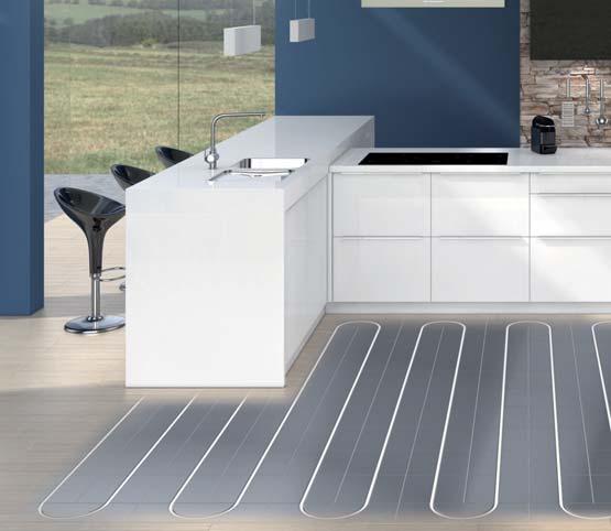
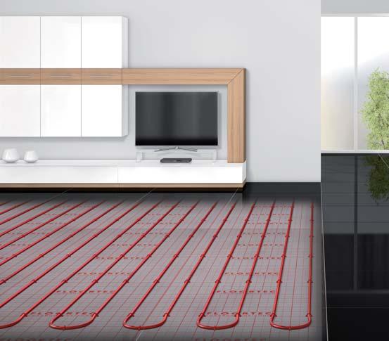
4 04 ECO - highest energy efficiency FULL-RANGE SUPPLIER. Efficient, comfortable and aesthetic heat distribution VOGEL&NOOT is the full-range supplier in innovative radiator and underfloor heating systems for any temperature range especially for low temperature operation with renewable energy sources. Panel, bathroom and design radiators, convectors Multifunctional panel radiators with the T6 technology, comfortable bathroom and individually configured design radiators as well as shapely convectors from VOGEL&NOOT, have a broad flow temperature range and an ideal range of applications to match. E2-technology The sign of highest energy efficiency The intelligent E2 technology provides quick control convenience even at low temperatures and always with the highest level of efficiency also in combination with underfloor heating systems. The ECO seal of quality on all radiators from VOGEL&NOOT stands for compatibility with all (renewable) energy sources and thus for economically as well as ecologically efficient heat distribution. FLOORTEC underfloor heating systems With its six different underfloor heating systems, VOGEL&NOOT fulfils all the requirements of cryogenic heat distribution. Continuously optimised components ensure an even better efficiency. The complete system warranty offers the highest level of safety and comfort for planning, installation and operation.


5 05 Efficient heat distribution for the planet VOGEL&NOOT has set itself the objective of providing the world with resource-conserving heat distribution solutions, because climate protection will only work when the heat generated is released efficiently into rooms. ENVIRONMENT AND CLIMATE PROTECTION. Contribution to the climate by improving the ecological balance As a leader in progressive thinking on green heat distribution using renewable energies, VOGEL&NOOT demonstrates a high level of responsibility about the efficient use of our planet and its resources, for example with a strict ECO training course, the focus on low temperature heat distribution and the compatibility with renewable energies as well as a permanent production optimisation and product development. VOGEL&NOOT has been a member of Klimabündnis Österreich since Innovation as the driving force for climate protection VOGEL&NOOT conducts intensive research & development and maintains a strong innovation network with internal and external energy and trend experts, universities and renowned research institutions. Renewable energies, the future of heat distribution Compatibility is an essential quality for heat distribution systems using renewable, low temperature energy sources such as heat pumps, solar technology, etc. VOGEL&NOOT radiators with the ECO quality seal ensure low CO 2 emissions and thermal comfort for all system temperatures in modern insulated buildings up to a flow temperature below 40 C. VOGEL&NOOT is a member of Klimabündnis Österreich. This network is active in 18 European countries and has set itself the objective of effectively reducing environmentally harmful emissions and protecting our planet s resources.


, which documents the special quality of the product")


6 06 Certified Quality QUALITY AS A SIGN OF MAXIMUM SAFETY Quality as a sign of maximum safety The radiators manufactured by VOGEL&NOOT meet numerous internationally recognised quality standards and the manufacturing processes at all of the production sites have been ISO certified. Furthermore, the quality and performance data of VOGEL&NOOT panel radiators are constantly reviewed and confirmed by accredited European institutions. VOGEL&NOOT panel radiators have also been awarded the seal of approval of the German Committee for Terms and Conditions of Sale (RAL), which documents the special quality of the product compared with many other radiator manufacturers. Bests with RAL Quality Seal For architects, designers and builders, the RAL seal of approval for VOGEL&NOOT radiators symbolises the high quality of the product in the areas of processing and handling. These quality assessments, which are controlled by independent institutions, vouch for the enduring safety and long life of service of the product. Highest customer confidence Our customers know that with each product, they can expect excellent properties in terms of the material, surface condition and durability. VOGEL&NOOT radiators thus exceed many requirements and outperform numerous standards (such as, for instance, the European Standard EN 442 or the CE marking). A perfected manufacturing process guarantees the best performances with precise welding, reliable leak-testing and glossy surface treatment - safety combined with a fantastic visual appearance!


7 Panel radiators Contents 07 PLAN RADIATORS PROFILE RADIATORS ULOW-E2 ULOW-E2 LOW-TEMPERATURE RADIATOR Introduction 08 Technical data 17 Temperature pairings and weight 18 T6-CENTRALLY CONNECTED RADIATOR Technical data 19 Connection modes 22 Temperature pairings and weight 36 HYGIENE T6-CENTRALLY CONNECTED RADIATOR Technical data 40 Connection modes 22 Temperature pairings and weight 42 T6-PLAN CENTRALLY CONNECTED RADIATOR Technical data 50 Connection modes 58 Temperature pairings and weight 55 MULTI-FUNCTIONAL VALVE RADIATOR Technical data 27 Connection modes 30 Temperature pairings and weight 36 HYGIENE COMPACT RADIATOR Technical data 40 Connection modes 35 Temperature pairings and weight 42 HYGIENE T6-PLAN CENTRALLY CONNECTED RADIATOR Technical data 59 Connection modes 58 Temperature pairings and weight 61 COMPACT RADIATOR Technical data 33 Connection modes 35 Temperature pairings and weight 36 REPLACEMENT PANEL RADIATOR Technical data 46 Connection modes 48 Temperature pairings and weight 49 1 VERTICAL RADIATORS VERTICAL- CENTRALLY CONNECTED RADIATOR Technical data 65 Temperature pairings and weight 67 PLAN-VERTICAL- CENTRALLY CONNECTED RADIATOR Technical data 68 Temperature pairings and weight 70 BASICS General technical information 71 Plan radiated heat-refl ector 72 Monclac-bracket 74 Mounting template 3/4 external thread 76 Transfer table 78 Tender offer documents are available to download at


8 08 ULOW-E2 LOW-TEMPERATURE RADIATOR Introduction ULOW-E2 LOW-TEMPERATURE RADIATOR Technology An unmatched concept The ULOW-E2 low-temperature radiator, with its E2 technology is the realisation of a unique product concept, that offers efficient, economic and aesthetic heat emission.


9 ULOW-E2 LOW-TEMPERATURE RADIATOR Introduction 09 1 ULOW-E2 Beauty and economy in one An avant-garde design meets all the demands of a modern interior and stylishly enhances any living space. Because of the small additional investment costs needed for the ULOW-E2 s higher effi ciency, it quickly pays for itself. Manual temperature control in each room makes for maximum comfort in every one of them. Powerful and intelligent On the one hand, the ULOW-E2 gives a high proportion of radiant heat thanks to its water-filled panels, whilst on the other, it provides optimised, on-demand convection. Intelligent control, switches between static and dynamic operation and ensures quick heat emission and short reaction times, with high efficiency and a maximum of thermal comfort at supply temperatures of 40 C and less.

.")


10 10 ULOW-E2 LOW-TEMPERATURE RADIATOR The advantages The advantages of the ULOW-E2 low-temperature radiator at a glance. Low-temperature compatible The ULOW-E2 low-temperature radiator gives problem-free use at supply temperatures of 40 C and less, with all modern, conventional energy sources (oil or gas burning heating systems, &c), as well as all renewable energy sources (heat pumps, solar heating, &c). Intelligent control What makes the ULOW-E2 so special is that it is fi tted with fans that enhance natural convection, combined with an intelligent control system that can switch between static and dynamic operation either fully automatically, or according to the user s operating requirements. The fans serve as a supplement and are only switched on when needed, as this equipment provides high basic performance even in static operation. High savings potential Choosing it in preference to other products currently available on the market can give you huge energy savings, because of the signifi cantly lower ambient operational temperatures. With the ULOW- E2, operating the entire heating system is much more energy-effi cient. State-of-the-art design The ULOW-E2 s extremely elegant plane optics and its futuristically reduced artistic style appeal to persons with a sophisticated awareness of their furnishings, whilst the rounded soft-line edges exude stylish harmony. VOGEL&NOOT are trend-setting trail blazers with their completely new round-aperture optics another prominent feature is the classy looking, intuitive touchpad control panel. Heat emission in next to no time and a short reaction time Because of its high proportion of radiant heat and its on-demand fan-optimised convection, the ULOW-E2 ensures fast heat emission and short reaction times. In winter any night-time drop in temperature or heat loss from ventilating room can be compensated for, no problem, in next to no time. Tried and tested central-connection technology In today s fl exible building industry pre-piping has become indispensible. In this respect central-connection technology contributes signifi cantly to reductions both in installation time and costs and in susceptibility to faults. It also ensures maximum freedom in planning and installation.


11 ULOW-E2 LOW-TEMPERATURE RADIATOR The advantages 11 ULOW-E2 Technology A higher proportion of radiant heat In contrast to simple convectors the ULOW-E2 gives a much higher proportion of radiant heat, thanks to its water-fi lled panels to front and rear. Ideal for renovations and new buildings After thermal renovation and the fi tting of a modern heating source, the conditions for installing the ULOW-E2 are ideal. We recommend using ULOW-E2 low-temperature radiators on their own in renovations, but in combination with other heat emission systems in new buildings. Versatile electrical connection To connect the ULOW-E2 to the power supply, there is a choice of two options a plug connection or a direct cable connection. The power cable length is fully adjustable. Extremely easy installation The ULOW-E2 is delivered as a ready to connect product, and can be installed just like any standard radiator - it s easy, effi cient, fl exible and inexpensive. Particularly with renovations this is very important. System compatibility Operating in combinations in new buildings, the ULOW-E2 is perfectly compatible with other low-temperature heat emission systems, such as under-fl oor heating, under-fl oor convectors, wall heating, &c. As the ambient operational temperatures are mutually consistent, it is possible to install both on a single heating circuit. Living in comfort all year round In winter the ULOW-E2 works as an effi cient low-temperature radiator, with high-level control quality, to give perfect heating comfort. And then the summer breeze-effect ensures that on hot days the atmosphere in your living area is pleasantly cool thanks to gentle movement of the air.

 are installed,")
12 12 ULOW-E2 LOW-TEMPERATURE RADIATOR Areas of application RENOVATION, A NEW BUILDING OR SIMPLY GREATER THERMAL COMFORT. Renovations: monovalent operation Provided thermal renovation ensures a good standard of insulation, or a modern heating source has been fitted, the conditions for installing the ULOW- E2 are ideal. Operation with all energy sources (oil, gas, firewood, pellets, district heating or a heat pump) at a supply temperature of 40 C and less is perfectly possible. In new buildings: combined operation In modern style new buildings good standards of thermal insulation already apply and modern reduced-temperature heating systems (oil- or gas-fired) are installed, or renewable low-temperature energy sources are used (firewood, pellets, and/or district heating or heat pumps). The ULOW-E2 with supply temperature as low as 40 C and less is compatible with these heat sources. For sure, the ULOW-E2 can in principle also be used for monovalent operation in new buildings. However, combined operation with other low-temperature heat-emission systems, such as underfloor heating, under-floor convectors, wall heating, &c is particularly recommended. Combined operation is recommended for spaces that require fast room heating and short reaction times (bedroom, fitness room, work space, etc.).


13 ULOW-E2 LOW-TEMPERATURE RADIATOR Comparison with commercially available fan convectors 13 THE UNIQUE ULOW-E2 CONCEPT. ULOW-E2 The ULOW-E2 as compared with commercially available fan convectors: Fan convectors generally provide either no radiant warmth or only very little. The ULOW-E2 combines convection and radiant heat, thanks to its water-charged panels. In static operation the ULOW-E2 is superior to commercially available fan convectors on account of its high level of basic performance. This is because aluminium heat exchangers without fan support are less efficient. With most fan convectors, the fans are switched on whenever the heater is in service. The ULOW-E2 has an intelligent control mechanism, which switches automatically between static and dynamic operation. It only starts the fans when it is turned full-on, or when additional output is required. Fan convectors are strictly limited in their designer- and architectural pretensions, because of their clumsy construction. With its distinctive round-hole-look, the ULOW E2 sets new standards in radiator design. Its slim profile and elegant plane surfaces are the perfect complement to any modern living environment. Maintenance and cleaning of fan convectors is usually an unpleasant, time-consuming chore. The ULOW-E2, by contrast, can be cleaned just like a standard flat radiator. The rows of fans just pull out to the side, with no tools required. With its high performance specifications, the ULOW-E2 offers top of the range price-for-quality value. Fan convectors are made up of very many individual parts, some of which are complex and can only be fitted on-site. By comparison, the ULOW-E2 is delivered as a ready-to-plug-in product. Fan convectors do not have central connections. With the ULOW-E2 these come as standard across the range, guaranteeing maximum flexibility for planning and installation. Installation of fan convectors is expensive and time consuming. The ULOW-E2 can for the most part be installed with no tools needed. ULOW-E2: slim profile and modern design FAN CONVECTORS: Clumsy appearance and broad bulky structure ULOW-E2: radiant heat and convection FAN CONVECTORS: little radiant heat


14 14 ULOW-E2 LOW-TEMPERATURE RADIATOR Functional and control elements Functional and control elements TOUCHPAD-CONTROL PANEL Thermostat head Temperature scale THERMOSTAT main switch ON/OFF Heating icon, RED Cooling icon, BLUE UP button DOWN button Temperature icon Boost button Heating/Cooling button Fans
 showing the setting selected.")
15 ULOW-E2 LOW-TEMPERATURE RADIATOR Functional and control elements 15 Functional and control elements Settings instructions The thermostat head (1) is always the radiator s MAIN CONTROL FUNCTION, with the temperature scale (2) showing the setting selected. The ULOW- E2 is equipped with a clearly arranged TOUCHPAD CONTROL PANEL, with which the settings for the radiator s IN- DIVIDUAL FUNCTIONS can be entered. The main switch ON/OFF (3) switches the electronics on or off. When the heating icon s (4) red light shows, the heating mode is on. The factory setting for desired room temperature on first operation is 22 C. With the UP button (6) or the DOWN button (7) you can reset the temperature in 1 C increments, between 18 and 26 C. The new setting is displayed by the LED temperature icon (8). The Boost button (9) activates Boost Mode, in which the power to the fans (11) is increased to its maximum value. The maximum duration of Boost Mode is preset by the factory at 120 mins. As ULOW-E2 Temperature settings 18 C 1 st LED dimly lights 18,5 C 1 st LED strong lights 19 C 1 st and 2 nd LED dimly lights 19,5 C 1 st and 2 nd LED strong lights 20 C 2 nd LED dimly lights 20,5 C 2 nd LED strong lights 21 C 2 nd and 3 rd LED dimly lights 21,5 C 2 nd and 3 rd LED strong lights 22 C 3 rd LED dimly lights 22,5 C 3 rd LED strong lights 23 C 3 rd and 4 th LED dimly lights 23,5 C 3 rd and 4 th LED strong lights 24 C 4 th LED dimly lights 24,5 C 4 th LED strong lights 25 C 4 th and 5 th LED dimly lights 25,5 C 4 th and 5 th LED strong lights 26 C 5 th LED dimly lights soon as the selected room temperature is reached, the system automatically switches to Comfort Mode. With the Heating/Cooling button (10) you can switch from heating operation to cooling operation, and the cooling icon (5) lights up in blue. For Dry Comfort Cooling operation some adaptations in the boiler house will be needed, particularly to ensure that temperatures do not fall below the dewpoint. In addition the thermostat head needs to be fully opened anti-clockwise, and with extremely high room temperatures it may also occasionally be necessary to remove the thermostat head. Pressing the Heating/Cooling button (10) again activates the Air Circulation Mode and the blue cooling icon (5) starts to blink. In this case the fans (11) operate independently of the temperature sensors. The factory-setting of 12 volts can be reduced to 8 or 5 volts, and vice versa, by pressing the UP (6) and DOWN (7) buttons. If you press the Heating/Cooling button (10) once more, you return to the heating mode. For more detailed information see the operating instructions, enclosed with every ULOW-E2 low-temperature radiator delivery.


16 16 ULOW-E2 LOW-TEMPERATURE RADIATOR Service access, electrical connection und secure wall mounting Service access, electrical connection und secure wall mounting Versatile electrical connection Connecting the ULOW-E2 to the power supply, can be done in a variety of ways and can fit in with every structural and architectural condition. The position of the cable is fully adjustable within an overall length of 1.20 m. Tool-free service access What is so special about service access for the ULOW-E2 is that not a single tool is required for removing and replacing the component parts. All functional units and electrical components are freely accessible and can be fitted by means of plug connections and clamp joints. This saves money and time for maintenance and cleaning. A ULOW-E2 is cleaned just the same way as a standard flat radiator. The fans sit on gliding cradles and can easily be slid out or in from the side of the radiator. Example: Standard plug connection. Example: Alternative direct cable connection, with or without on/off switch. The sliding cradles for the fans are made of extremely flexible and resistant plastic. They can be bent to an angle of 90. This is particularly useful for narrow niches and narrow side clearance with walls. Should the fan need to be replaced, press down the sliding cradle by hand and remove it from the plug connection/clamp-joint. Secure wall installation For wall-mounting the ULOW-E2, use only mounting brackets or wall-mounting systems with integrated connection locking.


. Packaging: 1. Cardboard packaging; 2. Edge protection; 3. Shrink wrapped. The device can be installed in packaging.")
17 ULOW-E2 LOW-TEMPERATURE RADIATOR Technical specifi cation 17 ULOW-E2 10 bar max. Connections: 4 x G ½ internal thread and 2 x G ¾ external thread, underside centre. Maximum positive operating pressure: Standard design: 10 bar max. Maximum operating temperature: 60 C Safety class: IP14 Supply voltage: 230 V Material: cold-rolled sheet steel conforming to EN 442-1, 1 mm thick zinc-plated front panel. Connecting dimensions: central distance between supply and return 50 mm. Casing: consists of a perforated metal top-cover and two closed removable side panels. Coating: 1. Primer coating conforming to DIN part 1, stoved at 190 C; 2. Especially robust electrostatic powder coating conforming to DIN part 2, in RAL 9016, stoved at 210 C. Standard design: powder coating in RAL 9016 (Traffic White). Packaging: 1. Cardboard packaging; 2. Edge protection; 3. Shrink wrapped. The device can be installed in packaging. Connection modes: all models are factory-fitted with mounting brackets and can optionally be connected as valve radiators with central connection or as compact radiators. With single-pipe systems, a one-pipe manifold is absolutely essential. The side panels and top-cover are allowed for in the performance specifications. Noise levels: comfort operation: between 20 and 25 db; boost operation: 34 db. These values apply at a distance of 2m, in conformity with VDI (Overall dimensions: x 1000 mm). Scope of delivery: thermostat valve with factory-adjusted k v configurations including mounting cap; drain plug, dummy plug and special vent plug, all factory sealed; as well as completely pre-installed fan sets with microprocessor and thermistor control unit; an integrated low-voltage transformer with ready to plug in mains cable; and a visually attractive operating panel (in the top cover), all included in the purchase price. Not designed for use with free-standing console-feet!
18 18 ULOW-E2 LOW-TEMPERATURE RADIATOR Heat outputs Heat outputs - ULOW-E2, model 22 PTM Overall height Overall length Mode of operation Static operation Comfort operation Boost operation Overall height (mm) Radiator exponent n (for 45/35/20, 40/35/20 und 35/30/20) 1,305 1,317 1,339 1,139 1,129 1,164 1,112 1,112 1,106 Overall length (mm) /35/20 40/35/20 35/30/ /35/20 40/35/20 35/30/ /35/20 40/35/20 35/30/ /35/20 40/35/20 35/30/ /35/20 40/35/20 35/30/ /35/20 40/35/20 35/30/ /35/20 40/35/20 35/30/ /35/20 40/35/20 35/30/ /35/20 40/35/20 35/30/ ULOW-E2 weight Overall height (mm) Overall length (mm) Model 22 PTM 22 PTM 22 PTM 400 kg 15,70 17,59 25,19 kg 22,43 25,20 36, kg 29,18 32,82 47, kg 36,11 40,62 59, kg 42,85 48,24 70, kg 49,69 55,94 82,37 1 kg 56,53 63,65 93, kg 63,46 71,45 105, kg 70,20 79,07 116,79

19 T6-CENTRALLY CONNECTED RADIATOR Technical data 19 T6-CENTRALLY CONNECTED RADIATOR. 1 ULOW-E2 Profile panel radiators 13 bar Connections 4 x internal thread G 1/2 and 2 x external thread G 3/4 bottom centre Test positive pressure 13 bar Technology 10 bar max. Max. positive operating pressure 10 bar max. Max. operating temperature 110 C Heat emission The specifi cation was verifi ed in accordance with DIN EN 442 at The Technical University, Stuttgart (Registration at WSP-Cert Product Certifi cation Centre, Stuttgart), under the numbers: Type 11 VM 0445 Type 21 VM-S 0447 Type 22 VM 0448 Type 33VM 0449 and in accordance with OENORM (Austrian standard) EN 442 at the Technological Commercial Museum, Vienna. Material T6-CENTRALLY CONNECTED RADI- ATORS are made of cold-rolled sheet steel, and in accordance with EN 442-1, with a stylish and robust fl uting with ribs at 40 mm intervals. Equipment Each T6-CENTRAL CONNECTION RA- DIATOR is equipped with an integrated T-valve set, and suitable for double-pipe and single-pipe systems with a single-pipe manifold; it comes with a fi t- ted valve top with a pre-set k v -value, a protective cap and welded suspension brackets on the back. The drain plug and the pivoting special vent plug, as well as the dummy plug are fi tted with seals. All types of radiator are equipped with a detachable top cover and two closed side panels. Paint coating 1. Undercoating in accordance with DIN part 1, stoved at 190 C. 2. Finish in accordance with DIN part 2, in standard colour 9016 (on request available in many standard colours and sanitary-ware colours at an extra charge), applied electrostatically in a modern powder coating facility. This especially resistant coating is stoved at an object temperature of 210 C. Packaging 1. Cardboard packaging 2. Edge protection 3. Shrink foil
20 20 T6-CENTRALLY CONNECTED RADIATOR Overview of models Overview of models Type 11 VM 21 VM-S 22 VM 33 VM single-layer einlagig with a mit convection einem Konvektionsblech sheet double-layer zweilagig with mit a convection einem Konvektionsblech sheet double-layer zweilagig with mit two zwei convection Konvektionsblechen sheets three-layers dreilagig with mit three drei convection Konvektionsblechen sheets Type 11 VM 21 VM-S 22 VM 33 VM Height Length up to 2400 up to 2 up to 2000 up to 2400 up to 3000 Steps all overall length starting with 400 mm available in steps of 200 mm, additionally 520, 720, 920, 1120 and 1320 mm up to 2000 up to 3000 up to 2000 up to 3000 up to 2200 up to 1800 Guarantee statements are available to download at


21 T6-CENTRALLY CONNECTED RADIATOR Description and delivery equipment 21 Description and delivery equipment The T6-CENTRALLY CONNECTED RA- DIATOR, with its welded-in set of T- shaped valves, sets new standards in the field of centre-connection technology. Besides its elegant appearance, the T6-CENTRALLY CONNECTED RA- DIATOR grabs the attention because of its unique patented features. It is suitable for all purposes and easy for the heating engineer to install. It also has many other striking advantages, as listed below: T6-CENTRALLY CONNECTED COMPLETE RADIATORS - wall bracket fastenings make this a fl exible solution VARIABLE CONNECTIONS - the built-in valve and its thermostat head can be switched from the right to the left-hand side with no need to turn the radiator and without crossing over the supply and return. VARIABLE TYPES - with all multi-layered radiators the distance between the connection and the wall is standardised (this also applies to all single-layered radiators, if a special angle fi sh-plate is used). VARIABLE SIZES - you are free to choose the overall radiator length and height at any time, and even subsequently change your mind. PERFECT PRE-ASSEMBLY - fi tting pre-installation piping and system testing are possible even without having the radiators there. Consequently T6-CENTRALLY CON- NECTED RADIATOR truly serves to solve your problems. To round off all the advantages mentioned before, the versatility of the T6-CENTRALLY CON- NECTED RADIATOR regarding style and colouring offers a wide scope for design. By using the removable, unique and colourful decor-clips you can give individuality, also subsequently. The T6-CENTRALLY CONNECTED RA- DIATOR is - with its welded in set of T-shaped valves - suitable for doublepipe installations as well as single-pipe installations, using a single-pipe manifold. Additionally to the central connection from the bottom, the sophisticated design makes possible other connections used at compact radiators, such as the single-sided and two-sided connection. Radiators are delivered ready for double-pipe installation and with a factory-adjusted k v -setting, appropriate to the radiator output. For district heating installations with a big difference between water supply and return temperature, a valve unit that allows a precise and stepless adjustment is available on request. By using universal supply and return connections, commercially available pipes (external thread 3 4 ) made of copper, steel, plastic or alloy, can be connected; the corresponding accessories and the commercially obtainable shut-off valve have to be used. The following thermostat heads can be directly fi tted at the radiator: RA 2000 and RAW by Danfoss, VK by Heimeier, D by Herz, thera DA by MNG, as well as UNI XD by Oventrop. The radiator will be delivered with a protective cap. The operation parameters are specifi ed with a positive operating pressure of 10 bar and an operating temperature of 110 C. With single-pipe installations, a cycle s maximum radiator power of about 10 kw at ΔT=T 1 -T 2 =20 K (at T 1 = 90 C) has to be taken into account. Thus the T6-CENTRALLY CONNECTED RADIATOR has to be regarded as revolutionary for the new generation of centrally-connected radiators. With this type of radiator - with its ideal functioning of the whole radiator-valve unit, its superb heating output, compared with the motivation to install thermostat heads, saving heating energy becomes evident. Our valve radiators connections (external thread G 3 4 ) comply in construction and tolerance with the specifi cations, in accordance with DIN V If conically sealed drain cocks are used (single-pipe and double-pipe operation), where an adjustment of tolerance of distance to the centre is not possible, we must repudiate liability for any damage connected to this. Therefore we recommend to use only flat sealed drain cocks, or drain cocks where an adjustment of tolerance of the distance to the centre is possible. T6-CENTRALLY CONNECTED RADIATOR
22 22 T6 AND T6-HYGIENE CENTRALLY CONNECTED RADIATOR Double-pipe operation - Adjustment tips for built-in valve X B A Danfoss RA 2000 Setting instructions: VOGEL&NOOT valve radiators are factory-fi tted for double-pipe installations. Each individual radiator is fi tted with a pre-adjusted valve insert, appropriate to the radiator output. The preset k v -value is also marked in colour on the front surface. G 3/4 A.G. 50 Detail X Einstellring gauge N 1234 Please note: Should customised adjustments be required, the pre-set kv-values can be altered as needed. Swapping the right-hand side built-in valve to the left-hand side is no problem at all at any time. Radiator are delivered with protective caps. After removing the protective cap (pos. A) the following thermostat heads can be fi tted directly to the builtin valve (pos. B): RA 2000, RAW by Danfoss, VK by Heimeier, D by Herz, thera DA by MNG and UNI XD by Oventrop. Markierung marking Heizkörperdurchfluss radiator ow rate [l/h] [l/h] default setting Voreinstellung N - kv=0, kv=0, kv=0, kv=0, kv=0, kv=0, kv=0, kv=0,13 k v -value chart Pre-setting 1,1 3,9 5,2 6,5 N 2 kv-value up to 0,13 0,30 0,42 0,56 0, Pressure Druckverlust drop [mbar] Chart 1 Pressure drop [mbar] double-pipe operation with a proportional deviation of 2K Colour of the adjustment ring white black green blue red Of course it is also possible to change the pre-adjusted valve setting when the equipment is operating at pressure.

23 T6-CENTRALLY CONNECTED RADIATOR Valve pre-adjustment 23 Hydraulic calibration The hydraulic calibration of the heat emission system has two essential effects: saving on energy costs and CO 2 reduction. It ensures that all radiators receive the required fl ow rate of heating water. This is the only way that optimal heat output performance be achieved, guaranteeing thermal comfort, with economical and ecologically responsible operation. Any radiator requires a specifi c fl ow rate of heating water, according to its position in the distribution system. The circulation pump serves to distribute heat in all rooms equally and in accordance with the required ambient temperature. Yet, in most systems the warm heating water fl ows back along the line of least resistance, which is usually through the radiator located next to the circulation pump. This means that the radiators furthest from the circulation pump are inadequately supplied with heating water, whereas the nearest are oversupplied! Very often the reason why rooms are inadequately heated or overheated is attributed to either an under-size pump or heating sources that are too weak. However, larger pumps, high supply temperatures and heating controls make the negative effects worse: lack of comfort and high energy costs, as well as higher CO 2 emissions and more noise. The only effective remedy for this is hydraulic calibration, with the appropriate k v -value, pre-adjusted by the factory. This makes the resistance of all the radiators in the distribution system similar, and they get an optimal rate of heating water fl ow. T6-CENTRALLY CONNECTED RADIATOR Factory pre-adjustment Advantages of the valve inserts in VOGEL&NOOT valve radiators VOGEL&NOOT valve radiators are already factory-fi tted with pre-set and adjustable valve inserts, appropriate to the heat output. The valve inserts fi tted as standard allow for 8 main k v -value settings and 7 intermediate settings. The factory-adjusted k v -value settings include 5 of 15 possible settings, and are calculated for standard heating systems with a pressure difference of 100 mbar. Continuously opening and infinitely variable control apron Finer adjustment Reliable operation More easily cleaned valve inserts Colour-coded valves Set k v -value immediately visible The advantages of factory-adjusted valve settings Optimal hydraulic calibration for buildings with operational areas up to 1,000m2 Better energy evaluation of buildings (DIN EN 18599) Credits for the Energy Passport Saves time and costs for heating planners, installers and plumbers Up to 6% energy saving, after hydraulic calibration Up to 20% less energy needed for circulation pump


24 24 T6-CENTRALLY CONNECTED RADIATOR Valve pre-adjustment The advantages of hydraulic calibration Up to 6% energy saving CO 2 reduction Increased comfort Complies with Energy-Effi ciency regulations A system without hydraulic calibration A system with hydraulic calibration
25 T6 AND T6-HYGIENE CENTRALLY CONNECTED RADIATOR Single-pipe operation - Factory-adjusted built-in valve 25 Single-pipe operation - Factory-adjusted built-in valve In single-pipe operation, setting the built-in valve on N. 50 B A Danfoss RA 2000 The radiator will be delivered with a protective cap. After removing the protective cap (item A) the following thermostat heads can be installed directly onto the built-in valve (item B): RA 2000 and RAW by Danfoss, VK by Heimeier, therada by MNG, as well as UNI XD by Oventrop. Panel radiators G 3/4 A.G. One pipe manifold water supply element return element 2 union nut cover for throttle screw ball valve external thread 3/4 1 Caution: During the installation take care that the return element 2 has been installed at the water return, and the supply element 1 at the water supply. Changing the built-in valve from the right- to the left-hand side can easily be done at any time. 50% 2 radiator Heizkörperanteil proportion 45% 40% 35% Kreiswasserdurchfluss 100 l/h Flow rate during one cycle 150 l/h 200 l/h 250 l/h 300 l/h 350 l/h 400 l/h 500 l/h l/h 2 1 / / / 4 Spindelverdrehungen spindle defl ection Einrohrverteiler one-pipe manifold 30% pressure Druckverlust drop [mbar] Chart 2 pressure drop [mbar] - single-pipe operation with a proportional deviation of 2K. 3 3 / 4 Default setting: radiator proportion 30%: 3,75 revolutions * radiator proportion 35%: 3,25 revolutions * radiator proportion 40%: 2,50 revolutions * radiator proportion 45%: 2,25 revolutions * radiator proportion 50%: 2,00 revolutions * *... when starting, turn the bypass spindle of the one-pipe manifold to the right as far as it will go. Of course it is also possible to change the pre-adjusted valve setting when the equipment is operating at pressure. Please take into account the maximum power per cycle (regarding single-pipe installations) of about 10 kw ΔT = T 1 -T 2 = 20 K (at T 1 = 90 C).

26 N 26 T6-CENTRALLY CONNECTED RADIATOR Zinc-plated version /Connection modes - double-pipe system Zinc-plated version - COMPACT RADIATORS and T6 CENTRAL CONNECTION RADIATORS With zinc-plated radiators attention should be paid to special ordering and delivery instructions: 4. Powder coating 3. Primer coat 2. Zinc-plated version 1. Untreated radiator All models of the series COMPACT RADIATORS and T6 CEN- TRAL CONNECTION RADIATORS are available Production is available only by special request. Radiators that have already been manufactured and delivered cannot be returned. The delivery period for this radiator is 4-6 weeks. The production is carried out for an additional charge to the currently recommended retail price. Our general warranty conditions apply. In areas of use that require higher corrosion protection, in rooms with aggressive surroundings and/or humid atmosphere (such as in indoor-swimming pools, saunas, public toilets, &c) we recommend using a zinc-plated version of our COMPACT RADIATORS and T6 CENTRAL CONNECTION RADIATORS. These radiators are galvanised, before the primer coat and powder coating is applied. Prior to ordering radiators for these areas of use you should get information about the planned location for installing the radiator and in accordance to this, defi ne its limits of use. Connection modes - double-pipe system A:Single-sided connection B: Connection both sides C: Connection on top Warning: Lower performance Caution: When using the T6-CENTRALLY CON- NECTED RADIATOR as a compact radiator, the 3/4 screwing caps made of plastic have to be replaced by nickel-plated brass caps (accessory). Available under the item number: AZ0PL000C Additionally the plastic part of the special vent plug has to be removed.


, under the numbers: Type 11 KV 0445 Type 21 KV-S 0447 Type")


; type 11 only available with brackets.")


27 MULTI-FUNCTIONAL VALVE RADIATOR Technical data 27 MULTI-FUNCTIONAL VALVE RADIATOR. Panel radiators 13 bar Connections 4 x internal thread G 1/2 2 x G 3/4 Test positive pressure 13 bar 10 bar max. Max. positive operating pressure 10 bar max. Max. operating temperature 110 C Heat emission The specification was verified in accordance with DIN EN 442 at The Technical University, Stuttgart (Registration at WSP-Cert Product Certification Centre, Stuttgart), under the numbers: Type 11 KV 0445 Type 21 KV-S 0447 Type 22 KV 0448 Type 33 KV 0449 and in accordance with OENORM (Austrian standard) EN 442 at the Technological Commercial Museum, Vienna. Material MULTI-FUNCTIONAL VALVE RADIA- TORS are made of cold-rolled sheet steel, in accordance with EN 442-1, with a stylish and robust fluting, with ribs at 40 mm intervals. Equipment Each MULTI-FUNCTIONAL VALVE RADIA- TOR is equipped with an integrated valve set, and suitable for double-pipe and single-pipe systems with a single-pipe manifold; it comes with a fitted valve top with a pre-set k v -value, a protective cap and welded suspension brackets on the back, (brackets only when defined as such); type 11 only available with brackets. The drain plug and the pivotable vent plug, as well as the dummy plug are fitted with seals. All radiators are equipped with a detachable top cover and two closed side panels. Paint coating 1. Undercoating in accordance with DIN part 1, stoved at 190 C. 2. Finish in accordance with DIN part 2, in standard colour 9016 (on request available in many standard colours and sanitary-ware colours at an extra charge), applied electrostatically in a modern powder coating facility. This especially resistant coating is stoved at an object temperature of 210 C. Packaging 1. Cardboard packaging 2. Edge protection 3. Shrink foil
28 28 MULTI-FUNCTIONAL VALVE RADIATOR Overview of models Overview of models Type 11 KV 21 KV-S 22 KV 33 KV single-layer with a convection sheet double-layer with a convection sheet double-layer with two convection sheets three-layers with three convection sheets Type 11 KV 21 KV-S 22 KV 33 KV Height Length up to 2400 up to 2 up to 2000 up to 2400 up to 3000 up to 2000 up to 3000 up to 2000 up to 3000 up to 2200 up to 2000 Steps any overall length starting with 400 mm available in steps of 200 mm, additionally 520, 720, 920, 1120 and 1320 mm


 per ring has to be taken into accout.")

29 MULTI-FUNCTIONAL VALVE RADIATOR Description and delivery equipment 29 Description and delivery equipment The MULTIFUNCTIONAL VALVE RADIATOR with its welded valve unit has been designed in a most trendsetting way: it can meet all requirements regarding connections. This radiator will convince you not only because of its simple and fast installation but also because of its versatility and elegant appearance, as the valve unit is covered up by the heating panel. What s more, through the optimal function of the whole radiator-valve unit, through the maximum heat output and, last but not least, through the motivation to install thermostat heads, saving heating energy becomes evident. be connected, using the corresponding accessories and the commercially obtainable shut-off valve. The decor-clips (standard make in standard colour 9016) offer many possibilities for design. They are available in many standard and sanitary-ware colours, as well as with metallic surfaces, i.e. gilded. The following thermostat heads can be installed directly onto the radiator: RA 2000 and RAW by Danfoss, VK by Heimeier, therada by MNG, as well as UNI XD by Oventrop. At delivery the radiator is equipped with a protective cap. The operation parameters are specifi ed as follows: positive operating pressure 10 bar, operating temperature 110 C. With single-pipe installations a maximum heat output of about 10 kw at ΔT=T 1 -T 2 =20 K (at T 1 = 90 C) per ring has to be taken into accout. MULTI- FUNCTIONAL VALVE RADIATOR The MULTIFUNCTIONAL VALVE RA- DIATOR with its welded valve unit is suitable for double-pipe as well as for single-pipe installations, using a onepipe manifold. Additionally to the connection possibility at the bottom, the sophisticated design also offers connection possibilities, known from compact radiators, such as single-sided or two-sided connections. The radiator is delivered ready for double-pipe installation, with a factory-adjusted k v -setting, appropriate to the radiator output. For district heating installations with a big difference between water supply and return temperature, a steplessly adjustable valve element is available on request. By using universal supply and return connections with external thread 3/4, commercially available pipes made of copper, precision steel or plastic, can
")
.")
30 30 MULTI-FUNCTIONAL VALVE RADIATOR Connection modes - double-pipe system Connection modes - double-pipe system A: Single-sided connection B: Connection both sides C: Connection on top (Warning: Lower performance) D: Single-sided connection Attention: If the multifunctional valve radiator is used as compact radiator, the crew caps made of plastic have to be replaced by nickel-plated brass caps (accessory). Order number: AZ0PL000C
31 N MULTI-FUNCTIONAL VALVE RADIATOR Adjustment tips for built-in valve 31 Adjustment tips for built-in valve X A B Danfoss RA 2000 Setting instructions: VOGEL&NOOT valve radiators are factory-fi tted for double-pipe installations. Each individual radiator is fi tted with a pre-adjusted valve insert, appropriate to the radiator output. The preset k v -value is also marked in colour on the front surface. MULTI- FUNCTIONAL VALVE RADIATOR Please note: Should customised adjustments be required, the pre-set k v -values can be altered as needed. Detail X Einstellring gauge N 1234 external thread G 3/4 3/4 Radiator are delivered with protective caps. After removing the protective cap (pos. A) the following thermostat heads can be fi tted directly to the builtin valve (pos. B): RA 2000, RAW by Danfoss, VK by Heimeier, D by Herz, thera DA by MNG and UNI XD by Oventrop. Markierung marking 567 radiator fl ow rate [l/h] default setting k v -value chart Pre-setting 1,1 3,9 5,2 6,5 N kv-value up to 0,13 0,30 0,42 0,56 0,72 Colour of the adjustment ring white black green blue red pressure drop presiune [mbar] Chart 1 Pressure drop [mbar] double-pipe operation with a proportional deviation of 2K. Of course it is also possible to change the pre-adjusted valve setting when the equipment is operating at pressure.
32 N 32 MULTI-FUNCTIONAL VALVE RADIATOR Single-pipe operation - factory-adjusted built-in valve Single-pipe operation - factory-adjusted built-in valve A In single-pipe operation, setting the built-in valve on N B Danfoss RA 2000 The radiator will be delivered with a protective cap. After removing the protective cap (item A) the following thermostat heads can be installed directly onto the built-in valve (item B): RA 2000 and RAW by Danfoss, VK by Heimeier, therada by MNG, as well as UNI XD by Oventrop. external thread G 3/4 3/4 One pipe manifold water supply element 1 return element 2 union nut cover for throttle screw ball valve external thread 3/4 Caution: During the installation take care that the return element 2 has been installed at the water return, and the supply element 1 at the water supply. Changing the built-in valve from the right- to the left-hand side can easily be done at any time. 50% 1 3 / 4 radiator Heizkörperanteil proportion 45% 40% 35% Kreiswasserdurchfluss 100 l/h Flow rate during one cycle 150 l/h 200 l/h 250 l/h 300 l/h 350 l/h 400 l/h 450 l/h 500 l/h l/h / 2 3 Spindelverdrehungen spindle defl ection VN Einrohrverteiler one-pipe manifold 30% pressure Druckverlust drop [mbar] [mbar] Chart 2 pressure drop [mbar] - single-pipe operation with a proportional deviation of 2K. 3 1 / 2 Default setting: radiator proportion 30%: 3,50 revolutions * radiator proportion 35%: 3,00 revolutions * radiator proportion 40%: 2,50 revolutions * radiator proportion 45%: 2,00 revolutions * radiator proportion 50%: 1,75 revolutions * *... when starting, turn the bypass spindle of the one-pipe manifold to the right as far as it will go.. Of course it is also possible to change the pre-adjusted valve setting when the equipment is operating at pressure. Please take into account the maximum power per cycle (regarding single-pipe installations) of about 10 kw ΔT = T 1 -T 2 = 20 K (at T 1 = 90 C).

33 COMPACT RADIATOR Technical data 33 COMPACT RADIATOR Panel radiators Connections 4 x internal thread G 1/2 10 bar max. Max. positive operating pressure 10 bar 13 bar Test positive pressure 13 bar max. Max. operating temperature 110 CMax. Heat emission The specifi cation was verifi ed in accordance with DIN EN 442 at The Technical University, Stuttgart (Registration at WSP-Cert Product Certifi cation Centre, Stuttgart), under the numbers: Type Type 11 K 0445 Type 21 K-S 0447 Type 22 K 0448 Type 33 K 0449 and in accordance with OENORM (Austrian standard) EN 442 at the Technological Commercial Museum, Vienna. Material COMPACT RADIATORS are made of cold-rolled sheet steel, and in accordance with EN 442-1, with a stylish and robust fluting, with ribs at 40 mm intervals. Equipment Each COMPACT RADIATOR is equipped with wall brackets that are welded onto the back. The radiator types 11 K, 21 K-S, 22 K and 33 K are equipped with a detachable top cover and two closed side panels. Paint coating 1. Undercoating in accordance with DIN part 1, stoved at 190 C. 2. Finish in accordance with DIN part 2, in standard colour 9016 (on request available in many standard colours and sanitary-ware colours at an extra charge), applied electro-statically in a modern powder coating facility. This especially resistant coating is stoved at an object temperature of 210 C. Packaging 1. Cardboard packaging 2. Edge protection 3. Shrink foil
34 34 COMPACT RADIATOR Overview of models OVERVIEW OF MODELS Type K 21 K-S 22 K 33 K single-layer single-layer einlagig with mit einem a convection Konvektionsblech sheet double-layer zweilagig mit with einem a convection Konvektionsblech sheet double-layer zweilagig mit with zwei two Konvektionsblechen convection sheets three-layers dreilagig mit with drei three Konvektionsblechen convection sheets Type K 21 K-S 22 K 33 K Height Length up to 1200 up up to up to to up to 2400 up to 2 up to 2000 up to 2400 up to 3000 up to 2000 up to 3000 up to 2000 up to 3000 up to 2200 up to 2000 Steps all overall length starting with 400 mm available in steps of 200 mm, additionally 520, 720, 920, 1120 and 1320 mm Guarantee statements are available to download at


35 COMPACT RADIATOR / HYGIENE COMPACT RADIATOR Connection modes - double-pipe and single-pipe system 35 Connection modes - double-pipe system A: Single-sided connection COMPACT RADIATOR B: Connection both sides C: Connection on top Warning: Lower performance Connection modes - single-pipe system COMPACT RADIATORS can easily be converted for a single-pipe connection, provided that four-way valves with a by-pass pipe are used.


36 36 T6-RADIATOR / MULTI-FUNCTIONAL RADIATOR / COMPACT RADIATOR Outputs - temperature group 90/70/20 C 360 views available at 90/70/20 C Height Side panels and top cover of COMPACT-, T6- and MULTI-FUNCTIONAL VALVE RADIATORS are taken into consideration in the heat outputs Radiator power data in watts, in accordance with DIN EN 442 supply temperature 90 - return temperature 70 - room temperature 20 C Length Type K 11 KV 11 VM Power 400 Watt 520 Watt Watt 720 Watt 800 Watt 920 Watt 1000 Watt 1120 Watt 1200 Watt 1320 Watt 1400 Watt 1 Watt 1800 Watt 2000 Watt 2200 Watt 2400 Watt 2 Watt 2800 Watt 3000 Watt Radiatorexponent n K-S 21 KV-S 21 VM-S K 22 KV 22 VM K 33 KV 33 VM K 11 KV 11 VM K-S 21 KV-S 21 VM-S K 22 KV 22 VM K 33 KV 33 VM K 11 KV 11 VM 21 K-S 21 KV-S 21 VM-S 22 K 22 KV 22 VM 33 K 33 KV 33 VM K 11 KV 11 VM 21 K-S 21 KV-S 21 VM-S 22 K 22 KV 22 VM 33 K 33 KV 33 VM K 11 KV 11 VM Type programme COMPACT Radiator T6-Centrally connected radiator and MULTI-FUNCTIONAL VALVE Radiator The availability of any type of radiator, as well as range of sizes, is in accordance with the production programme, as stated in the price list ,274 1,330 1,327 1,329 1,331 1,283 1,342 1,334 1,353 1,357 1,292 1,330 1,323 1,334 1,351 1,301 1,319 1,310 1,343 1,333 1,305 1,332 1,321 1,340 1, K-S 21 KV-S 21 VM-S K 22 KV 22 VM K 33 KV 33 VM
37 T6-RADIATOR / MULTI-FUNCTIONAL RADIATOR / COMPACT RADIATOR Outputs - temperature group 75/65/20 C and 70/55/20 C 37 75/65/20 C Height Side panels and top cover of COMPACT-, T6- and MULTI-FUNCTIONAL VALVE RADIATORS are taken into consideration in the heat outputs Radiator power data in watts, in accordance with DIN EN 442 supply temperature 75 - return temperature 65 - room temperature 20 C Length Type K 11 KV 11 VM Power 400 Watt 520 Watt Watt 720 Watt 800 Watt 920 Watt 1000 Watt 1120 Watt 1200 Watt 1320 Watt 1400 Watt 1 Watt 1800 Watt 2000 Watt 2200 Watt 2400 Watt 2 Watt 2800 Watt 3000 Watt Radiatorexponent n K-S 21 KV-S 21 VM-S K 22 KV 22 VM K 33 KV 33 VM K 11 KV 11 VM K-S 21 KV-S 21 VM-S K 22 KV 22 VM K 33 KV 33 VM K 11 KV 11 VM 21 K-S 21 KV-S 21 VM-S 22 K 22 KV 22 VM 33 K 33 KV 33 VM K 11 KV 11 VM 21 K-S 21 KV-S 21 VM-S 22 K 22 KV 22 VM 33 K 33 KV 33 VM K 11 KV 11 VM Type programme COMPACT Radiator T6-Centrally connected radiator and MULTI-FUNCTIONAL VALVE Radiator ,274 1,330 1,327 1,329 1,331 1,283 1,342 1,334 1,353 1,357 1,292 1,330 1,323 1,334 1,351 1,301 1,319 1,310 1,343 1,333 1,305 1,332 1,321 1,340 1, K-S 21 KV-S 21 VM-S K 22 KV 22 VM K 33 KV 33 VM Panel radiators The availability of any type of radiator, as well as range of sizes, is in accordance with the production programme, as stated in the price list. 70/55/20 C Height Side panels and top cover of COMPACT-, T6- and MULTI-FUNCTIONAL VALVE RADIATORS are taken into consideration in the heat outputs Radiator power data in watts, in accordance with DIN EN 442 supply temperature 70 - return temperature 55 - room temperature 20 C Length Type K 11 KV 11 VM Power 400 Watt 520 Watt Watt 720 Watt 800 Watt 920 Watt 1000 Watt 1120 Watt 1200 Watt 1320 Watt 1400 Watt 1 Watt 1800 Watt 2000 Watt 2200 Watt 2400 Watt 2 Watt 2800 Watt 3000 Watt Radiatorexponent n K-S 21 KV-S 21 VM-S K 22 KV 22 VM K 33 KV 33 VM K 11 KV 11 VM K-S 21 KV-S 21 VM-S K 22 KV 22 VM K 33 KV 33 VM K 11 KV 11 VM 21 K-S 21 KV-S 21 VM-S 22 K 22 KV 22 VM 33 K 33 KV 33 VM K 11 KV 11 VM 21 K-S 21 KV-S 21 VM-S 22 K 22 KV 22 VM 33 K 33 KV 33 VM K 11 KV 11 VM Type programme COMPACT Radiator T6-Centrally connected radiator and MULTI-FUNCTIONAL VALVE Radiator The availability of any type of radiator, as well as range of sizes, is in accordance with the production programme, as stated in the price list ,274 1,330 1,327 1,329 1,331 1,283 1,342 1,334 1,353 1,357 1,292 1,330 1,323 1,334 1,351 1,301 1,319 1,310 1,343 1,333 1,305 1,332 1,321 1,340 1, K-S 21 KV-S 21 VM-S K 22 KV 22 VM K 33 KV 33 VM
38 38 T6-RADIATOR / MULTI-FUNCTIONAL RADIATOR / COMPACT RADIATOR Outputs - temperature group 55/45/20 C and 45/40/20 C 55/45/20 C Height Side panels and top cover of COMPACT-, T6- and MULTI-FUNCTIONAL VALVE RADIATORS are taken into consideration in the heat outputs Radiator power data in watts, in accordance with DIN EN 442 supply temperature 55 - return temperature 45 - room temperature 20 C Length Type K 11 KV 11 VM Power 400 Watt 520 Watt Watt 720 Watt 800 Watt 920 Watt 1000 Watt 1120 Watt 1200 Watt 1320 Watt 1400 Watt 1 Watt 1800 Watt 2000 Watt 2200 Watt 2400 Watt 2 Watt 2800 Watt 3000 Watt Radiatorexponent n K-S 21 KV-S 21 VM-S K 22 KV 22 VM K 33 KV 33 VM K 11 KV 11 VM K-S 21 KV-S 21 VM-S K 22 KV 22 VM K 33 KV 33 VM K 11 KV 11 VM 21 K-S 21 KV-S 21 VM-S 22 K 22 KV 22 VM 33 K 33 KV 33 VM K 11 KV 11 VM 21 K-S 21 KV-S 21 VM-S 22 K 22 KV 22 VM 33 K 33 KV 33 VM K 11 KV 11 VM Type programme COMPACT Radiator T6-Centrally connected radiator and MULTI-FUNCTIONAL VALVE Radiator The availability of any type of radiator, as well as range of sizes, is in accordance with the production programme, as stated in the price list ,274 1,330 1,327 1,329 1,331 1,283 1,342 1,334 1,353 1,357 1,292 1,330 1,323 1,334 1,351 1,301 1,319 1,310 1,343 1,333 1,305 1,332 1,321 1,340 1, K-S 21 KV-S 21 VM-S K 22 KV 22 VM K 33 KV 33 VM /40/20 C Height Side panels and top cover of COMPACT-, T6- and MULTI-FUNCTIONAL VALVE RADIATORS are taken into consideration in the heat outputs Radiator power data in watts, in accordance with DIN EN 442 supply temperature 45 - return temperature 40 - room temperature 20 C Length Type K 11 KV 11 VM Power 400 Watt 520 Watt Watt 720 Watt 800 Watt 920 Watt 1000 Watt 1120 Watt 1200 Watt 1320 Watt 1400 Watt 1 Watt 1800 Watt 2000 Watt 2200 Watt 2400 Watt 2 Watt 2800 Watt 3000 Watt Radiatorexponent n K-S 21 KV-S 21 VM-S K 22 KV 22 VM K 33 KV 33 VM K 11 KV 11 VM K-S 21 KV-S 21 VM-S K 22 KV 22 VM K 33 KV 33 VM K 11 KV 11 VM 21 K-S 21 KV-S 21 VM-S 22 K 22 KV 22 VM 33 K 33 KV 33 VM K 11 KV 11 VM 21 K-S 21 KV-S 21 VM-S 22 K 22 KV 22 VM 33 K 33 KV 33 VM K 11 KV 11 VM Type programme COMPACT Radiator T6-Centrally connected radiator and MULTI-FUNCTIONAL VALVE Radiator The availability of any type of radiator, as well as range of sizes, is in accordance with the production programme, as stated in the price list ,274 1,330 1,327 1,329 1,331 1,283 1,342 1,334 1,353 1,357 1,292 1,330 1,323 1,334 1,351 1,301 1,319 1,310 1,343 1,333 1,305 1,332 1,321 1,340 1, K-S 21 KV-S 21 VM-S K 22 KV 22 VM K 33 KV 33 VM
39 T6-RADIATOR / MULTI-FUNCTIONAL RADIATOR / COMPACT RADIATOR Weights 39 T6 / MULTI-FUNCTIONAL Weight in kg of T6-CENTRALLY connected and MULTI-FUNCTIONAL VALVE RADIATORS Height Type Length weight 400 kg 520 kg kg 720 kg 800 kg 920 kg 1000 kg 1120 kg 1200 kg 1320 kg 1400 kg 1 kg 1800 kg 2000 kg 2200 kg 2400 kg 2 kg 2800 kg 3000 kg 11 KV 11 VM 5,67 6,80 7,56 8,69 9,45 10,58 11,34 12,48 13,23 14,62 15,37 17,26 19,16 21,05 22,94 25,33 21KV-S 21VM-S 7,75 9,53 10,72 12,50 13,69 15,54 16,72 18,51 19,69 21,48 22,73 25,70 28,84 31,81 34,78 37,75 22 KV 22 VM 8,94 11,08 12,51 14,65 16,08 18,31 19,74 21,88 23,31 25,45 26,97 30,54 34,30 37,87 41,44 45,02 48,59 52,16 55,73 33 KV 33 VM 12,93 16,13 18,27 21,48 23,61 26,95 29,09 32,30 34,44 37,64 39,91 45,26 50,84 56,18 61,52 66,87 72,21 77,55 82,89 11 KV 11 VM 7,08 8,62 9,64 11,17 12,20 13,73 14,75 16,28 17,31 19,14 20,17 22,72 25,28 27,84 30,39 33,56 21KV-S 21VM-S 9,78 12,18 13,78 16,18 17,78 20,24 21,84 24,24 25,84 28,24 29,90 33,90 38,07 42,07 46,07 50,06 22 KV 22 VM 11,50 14,44 16,41 19,35 21,31 24,34 26,30 29,24 31,21 34,15 36,20 41,10 46,20 51,10 56,01 60,91 65,82 70,72 75,63 33 KV 33 VM 16,74 21,14 24,08 28,48 31,42 35,96 38,90 43,30 46,24 50,64 53,72 61,06 68,64 75,98 83,32 11 KV 11 VM 7,91 9,66 10,83 12,58 13,75 15,50 16,66 18,42 19,58 21,64 22,81 25,72 28,64 31,56 34,48 38,01 40,93 21KV-S 21VM-S 11,34 14,18 16,07 18,90 20,79 23,70 25,59 28,42 30,32 33,15 35,11 39,83 44,73 49,46 54,19 58,91 63,64 68,37 73,09 22 KV 22 VM 13,10 16,48 18,73 22,11 24,37 27,83 30,09 33,47 35,72 39,10 41,44 47,07 52,90 58,53 64,17 69,80 75,43 81,07 86,70 33 KV 33 VM 19,10 24,16 27,53 32,59 35,96 41,16 44,53 49,59 52,96 58,02 61,53 69,96 78,63 87,06 95,49 11 KV 11 VM 8,69 10,64 11,95 13,90 15,21 17,16 18,47 20,43 21,73 23,99 25,30 28,56 31,82 35,08 38,34 42,21 45,47 21KV-S 21VM-S 12,83 16,08 18,25 21,49 23,66 26,98 29,14 32,39 34,56 37,81 40,04 45,46 51,04 56,46 61,87 67,29 72,70 78,12 83,54 22 KV 22 VM 14,63 18,42 20,95 24,74 27,27 31,15 33,68 37,47 40,00 43,80 46,41 52,74 59,25 65,57 71,89 78,22 84,54 90,86 97,18 33 KV 33 VM 21,35 27,03 30,81 36,49 40,27 46,08 49,87 55,54 59,33 65,01 68,93 78,39 88,09 97,55 107,01 11 KV 11 VM 12,03 14,96 16,92 19,85 21,80 24,73 26,68 29,61 31,56 34,80 36,75 41,63 46,51 51,40 21KV-S 21VM-S 18,48 23,37 26,63 31,52 34,78 39,74 43,00 47,89 51,15 56,03 59,36 67,51 75,83 83,98 22 KV 22 VM 21,13 26,85 30,67 36,39 40,20 46,01 49,83 55,55 59,37 65,09 68,99 78,53 88,26 97,80 33 KV 33 VM 31,01 39,58 45,29 53,86 59,57 68,27 73,98 82,55 88,26 96,82 102,67 116,94 131,46 Panel radiators Type programme T6-CENTRALLY CONNECTED RADIATOR and MULTI-FUNCTIONAL VALVE RADIATOR The availability of any type of radiator, as well as range of sizes, is in accordance with the production programme, as stated in the price list. COMPACT Height Weight in kg of COMPACT RADIATORS Type K 21 K-S 22 K 33 K K 21 K-S 22 K 33 K K 21 K-S 22 K 33 K K 21 K-S 22 K 33 K K 21 K-S 22 K 33 K Length weight 400 kg 3,29 4,91 6,99 8,18 12,17 4,01 6,31 9,01 10,73 15,97 4,73 7,12 10,55 12,31 18,31 5,42 7,86 12,01 13,80 20,53 7,71 11,14 17,59 20,23 30, kg 4,00 6,05 8,78 10,33 15,38 4,93 7,84 11,41 13,67 20,37 5,88 8,87 13,38 15,69 23,37 6,77 9,82 15,26 17,60 26,20 9,74 14,07 22,48 25,96 38,69 kg 4,47 6,81 9,96 11,76 17,52 5,55 8,87 13,01 15,63 23,31 6,64 10,03 15,28 17,94 26,74 7,67 11,12 17,42 20,13 29,99 11,09 16,02 25,74 29,77 44, kg 5,18 7,94 11,75 13,90 20,72 6,47 10,40 15,40 18,58 27,71 7,78 11,79 18,11 21,32 31,80 9,02 13,08 20,67 23,92 35,66 13,12 18,95 30,63 35,50 52, kg 5,66 8,70 12,93 15,33 22,86 7,09 11,42 17,00 20,54 30,65 8,54 12,95 20,00 23,57 35,17 9,91 14,39 22,84 26,45 39,45 14,48 20,91 33,89 39,31 58, kg 6,37 9,83 14,78 17,56 26,20 8,02 12,96 19,47 23,57 35,19 9,68 14,70 22,90 27,04 40,36 11,26 16,34 26,15 30,33 45,26 16,51 23,83 38,84 45,12 67, kg 6,84 10,59 15,97 18,99 28,34 8,63 13,98 21,07 25,53 38,13 10,45 15,87 24,79 29,29 43,74 12,16 17,65 28,32 32,86 49,05 17,86 25,79 42,10 48,94 73, kg 7,55 11,72 17,75 21,13 31,54 9,56 15,51 23,47 28,47 42,53 11,59 17,62 27,63 32,67 48,79 13,51 19,60 31,57 36,65 54,72 19,89 28,72 46,99 54,66 81, kg 8,02 12,48 18,94 22,56 33,68 10,18 16,53 25,07 30,43 45,47 12,35 18,79 29,52 34,93 52,17 14,41 20,91 33,74 39,18 58,51 21,25 30,67 50,25 58,48 87, kg 13,86 20,72 24,70 36,89 18,37 27,47 33,38 49,87 13,67 20,85 32,36 38,31 57,22 15,94 23,17 36,98 42,97 64,18 23,46 33,90 55,14 64,20 95, kg 14,62 21,98 26,21 39,16 19,39 29,13 35,42 52,94 14,43 22,01 34,31 40,65 60,73 16,83 24,47 39,22 45,59 68,11 24,81 35,86 58,47 68,10 101,77 1 kg 16,51 24,95 29,79 44,50 21,95 33,13 40,33 60,29 16,60 24,93 39,04 46,28 69,16 19,35 27,73 44,63 51,91 77,57 40,74 66,62 77,64 116, kg 18,40 28,09 33,55 50,08 24,51 37,30 45,43 67,87 18,60 27,85 43,94 52,11 77,84 21,69 30,99 50,22 58,43 87,27 45,62 74,94 87,37 130, kg 20,30 31,06 37,12 55,43 27,06 41,30 50,33 75,21 20,51 30,77 48,67 57,74 86,27 23,93 34,26 55,63 64,75 96,73 50,50 83,09 96,91 144, kg 22,19 34,03 40,69 60,77 29,62 45,29 55,24 82,55 22,41 33,68 53,39 63,37 94,70 26,18 37,52 61,05 71,07 106, kg 24,58 37,00 44,26 66,11 32,78 49,29 60,14 24,31 37,21 58,12 69,01 28,43 41,39 66,47 77,39 2 kg 47,83 71,45 65,05 40,13 62,85 74,64 30,68 44,65 71,88 83, kg 51,41 76,80 69,95 67,57 80,28 77,30 90, kg 54,98 82,14 74,86 72,30 85,91 82,71 96,36 Type programme COMPACT RADIATOR The availability of any type of radiator, as well as range of sizes, is in accordance with the production programme, as stated in the price list.


40 40 HYGIENE RADIATOR Technical data HYGIENE RADIATOR HYGIENE COMPACT RADIATOR Connections: 4 x G 1/2 I. G. T6-HYGIENE CENTRALLY CONNECTED RADIATOR Connections: 4 x G 1/2 I. G. and 2 x G 3/4 A. G. lower edge, in the centre The proof of suitability for the installation of HYGIENE COMPACT RADIA- TORS and T6 HYGIENE CENTRALLY CONNECTED RADIATORS in rooms with particular hygienic requirements is highlighted by the hygiene certifi cate issued by Ernst Moritz Arndt University of Greifswald. The HYGIENE RADIATORS have been specially designed for use in hospitals and for installation in rooms subject to particular hygiene requirements. Advantages: No collection of dust and dirt on covers or sides Large inner separation distance without small-scale structures Easy to clean Rounded corners and edges, fi nished to a high level In order to offer the necessary alternatives for installation as well as complying with the hygiene requirements and guidelines, the hygiene radiators are available in T6 and compact designs.
41 HYGIENE COMPACT RADIATOR / T6-HYGIENE CENTRALLY CONNECTED RADIATOR Overview of models 41 Overview of models Type VM VM VM Panel radiators single-layer double-layer triple-layer Type 10 / 10 VM 20 / 20 VM 30 / 30 VM Height Length Gradation up to 1200 up to 2400 up to 2 up to 1400 up to 2400 up to 3000 up to 2000 up to 3000 All overall lengths from 400 m in gradations of 200 mm; also 520, 720, 920, 1120 and 1320 mm up to 2200 up to 1800 Twin-pipe operation, single-pipe operation, types of connection N.B.: Please refer to the appropriate sections concerning the T6 CENTRAL- LY CONNECTED RADIATOR on pages for technical information on the connection settings. Guarantee statements are available to download at


42 42 HYGIENE COMPACT RADIATOR / T6-HYGIENE CENTRALLY CONNECTED RADIATOR Outputs - temperature group 90/70/20 C 360 views available at 90/70/20 C Output data in watts in accordance with DIN EN 442 and/or ÖNORM EN 442 Feed temperature 90 - return temperature 70 - room temperature 20 C Height Length Type VM Output VM VM VM VM VM VM 400 Watt Watt Watt Watt Watt Watt Watt Watt Watt Watt Watt Watt Watt Watt Watt Watt Watt Watt Watt Radiator exponent n 1,274 1,278 1,288 1,283 1,282 1,288 1,292 1,287 1,288 1,301 1,291 1,288 1,305 1,294 1,317 Model range HYGIENE COMPACT RADIATORS and T6-HYGIENE CENTRE-CONNECTION RADIATORS The availability of any type of radiator, as well as range of sizes, is in accordance with the production programme, as stated in the price list VM VM VM VM VM VM VM VM
43 HYGIENE COMPACT RADIATOR / T6-HYGIENE CENTRALLY CONNECTED RADIATOR 43 Outputs - temperature group 75/65/20 C and 70/55/20 C 75/65/20 C Output data in watts in accordance with DIN EN 442 and/or ÖNORM EN 442 Feed temperature 75 - return temperature 65 - room temperature 20 C Height Length Type VM Output VM VM VM VM 400 Watt Watt Watt Watt Watt Watt Watt Watt Watt Watt Watt Watt Watt Watt Watt Watt Watt Watt Watt Radiator exponent n 1,274 1,278 1,288 1,283 1,282 1,288 1,292 1,287 1,288 1,301 1,291 1,288 Model range HYGIENE COMPACT RADIATORS and T6-HYGIENE CENTRE-CONNECTION RADIATORS VM VM VM VM VM VM VM VM VM VM ,305 1,294 1,317 Panel radiators The availability of any type of radiator, as well as range of sizes, is in accordance with the production programme, as stated in the price list. 70/55/20 C Output data in watts in accordance with DIN EN 442 and/or ÖNORM EN 442 Feed temperature 70 - return temperature 55 - room temperature 20 C Height Length 400 Watt Type VM Output VM VM VM VM VM VM VM VM VM VM VM VM VM VM Watt Watt Watt Watt Watt Watt Watt Watt Watt Watt Watt Watt Watt Watt Watt Watt Watt Watt Radiator exponent n 1,274 1,278 1,288 1,283 1,282 1,288 1,292 1,287 1,288 1,301 1,291 1,288 1,305 1,294 1,317 Model range HYGIENE COMPACT RADIATORS and T6-HYGIENE CENTRE-CONNECTION RADIATORS The availability of any type of radiator, as well as range of sizes, is in accordance with the production programme, as stated in the price list.
44 44 HYGIENE COMPACT RADIATORS / T6-HYGIENE CENTRALLY CONNECTED RADIATOR Outputs - temperature group 55/45/20 C and 45/40/20 C 55/45/20 C Output data in watts in accordance with DIN EN 442 and/or ÖNORM EN 442 Feed temperature 55 - return temperature 45 - room temperature 20 C Height Length Type VM Output VM VM VM VM VM VM VM VM VM VM VM VM VM VM 400 Watt Watt Watt Watt Watt Watt Watt Watt Watt Watt Watt Watt Watt Watt Watt Watt Watt Watt Watt Radiator exponent n 1,274 1,278 1,288 1,283 1,282 1,288 1,292 1,287 1,288 1,301 1,291 1,288 1,305 1,294 1,317 Model range HYGIENE COMPACT RADIATORS and T6-HYGIENE CENTRE-CONNECTION RADIATORS The availability of any type of radiator, as well as range of sizes, is in accordance with the production programme, as stated in the price list. 45/40/20 C Output data in watts in accordance with DIN EN 442 and/or ÖNORM EN 442 Feed temperature 45 - return temperature 40 - room temperature 20 C Height Length 400 Watt Type VM Output VM VM VM VM VM VM VM VM VM VM VM VM VM VM Watt Watt Watt Watt Watt Watt Watt Watt Watt Watt Watt Watt Watt Watt Watt Watt Watt Watt Radiator exponent n 1,274 1,278 1,288 1,283 1,282 1,288 1,292 1,287 1,288 1,301 1,291 1,288 1,305 1,294 1,317 Model range HYGIENE COMPACT RADIATORS and T6-HYGIENE CENTRE-CONNECTION RADIATORS The availability of any type of radiator, as well as range of sizes, is in accordance with the production programme, as stated in the price list.
45 HYGIENE COMPACT RADIATORS / T6-HYGIENE CENTRALLY CONNECTED RADIATOR Weights 45 T6-HYGIENE Height Weight in kg for T6-HYGIENE centre-connection radiators Type 10 VM 20 VM 30 VM 10 VM 20 VM 30 VM 10 VM 20 VM 30 VM 10 VM 20 VM 30 VM 10 VM 20 VM 30 VM Length Weight 400 kg 4,05 6,30 9,16 4,78 7,76 11,35 5,53 9,24 13,54 6,25 10,66 15,64 8,60 15,24 22,45 Panel radiators 520 kg 4,76 7,69 11,23 5,71 9,59 14,07 6,67 11,51 16,93 7,59 13,33 19,64 10,63 19,26 28,46 kg 5,23 8,62 12,62 6,33 10,80 15,88 7,43 13,02 19,17 8,49 15,12 22,30 11,99 21,95 32, kg 5,94 10,01 14,69 7,25 12,63 18,61 8,57 15,27 22,56 9,84 17,79 26,29 14,01 25,97 38, kg 6,41 10,94 16,07 7,87 13,85 20,43 9,33 16,79 24,80 10,74 19,57 28,95 15,38 28,65 42, kg 7,12 12,39 18,29 8,79 15,73 23,29 10,47 19,11 28,32 12,08 22,31 33,09 17,40 32,75 48, kg 7,59 13,32 19,67 9,41 16,96 25,10 11,23 20,62 30,58 12,99 24,10 35,75 18,75 35,43 52, kg 8,30 14,72 21,75 10,33 18,78 27,83 12,39 22,88 33,95 14,34 26,77 39,75 20,79 39,46 58, kg 8,78 15,64 23,12 10,95 19,99 29,65 13,15 24,39 36,20 15,23 28,55 42,41 22,14 42,13 62, kg 17,03 25,20 21,82 32,36 14,46 26,66 39,58 16,76 31,23 46,41 24,35 46,16 68, kg 18,02 26,72 23,10 34,32 15,23 28,22 41,97 17,66 33,08 49,21 25,70 48,92 72,86 1 kg 20,34 30,18 26,14 38,85 17,40 32,00 47,60 20,18 37,54 55,87 55,63 82, kg 22,83 33,88 29,36 43,64 19,39 35,93 53,47 22,51 42,16 62,77 62,50 93, kg 25,15 37,33 32,40 48,17 21,30 39,71 59,09 24,76 46,62 69,42 69,21 103, kg 27,47 40,79 35,43 52,72 23,20 43,48 64,72 27,00 51,08 76, kg 29,79 44,25 38,48 25,11 47,24 29,25 55,55 2 kg 47,70 51,02 31,50 60, kg 51,16 54,78 64, kg 54,62 58,56 68,92 Typenprogramm T6-HYGIENE centre-connection radiators The availability of any type of radiator, as well as range of sizes, is in accordance with the production programme, as stated in the price list. HYGIENE COMPACT Weights in kg for HYGIENE compact radiators Height Type Length Weight 400 kg 3,29 5,55 8,41 4,01 6,99 10,57 4,73 8,45 12,75 5,42 9,83 14,82 7,70 14,34 21, kg 4,00 6,94 10,48 4,94 8,82 13,30 5,87 10,71 16,14 6,77 12,51 18,81 9,74 18,36 27,57 kg 4,48 7,87 11,87 5,55 10,03 15,11 6,64 12,23 18,38 7,67 14,29 21,48 11,09 21,05 31, kg 5,19 9,26 13,94 6,48 11,86 17,84 7,78 14,48 21,77 9,01 16,96 25,47 13,12 25,07 37, kg 5,66 10,18 15,32 7,09 13,07 19,66 8,54 15,99 24,01 9,91 18,75 28,13 14,48 27,76 41, kg 6,37 11,64 17,53 8,02 14,96 22,52 9,68 18,32 27,53 11,26 21,49 32,26 16,51 31,86 47, kg 6,84 12,56 18,91 8,64 16,18 24,33 10,44 19,82 29,78 12,17 23,27 34,93 17,86 34,53 51, kg 7,55 13,96 20,99 9,56 18,00 27,05 11,59 22,09 33,16 13,51 25,95 38,93 19,90 38,56 57, kg 8,02 14,89 22,37 10,18 19,22 28,87 12,35 23,60 35,41 14,41 27,73 41,59 21,25 41,24 61, kg 16,28 24,45 21,05 31,59 13,67 25,86 38,79 15,94 30,40 45,59 23,46 45,27 67, kg 17,27 25,97 22,33 33,55 14,44 27,43 41,18 16,84 32,26 48,39 24,81 48,03 71,96 1 kg 19,59 29,43 25,37 38,08 16,60 31,21 46,81 19,35 36,71 55,05 54,73 81, kg 22,08 33,12 28,58 42,87 18,60 35,14 52,67 21,69 41,34 61,95 61,61 92, kg 24,40 36,58 31,63 47,40 20,50 38,92 58,30 23,93 45,80 68,60 68,32 102, kg 26,71 40,04 34,66 51,95 22,41 42,68 63,93 26,18 50,25 75, kg 29,04 43,50 37,70 24,32 46,45 28,43 54,72 2 kg 46,95 50,22 30,67 59, kg 50,41 53,99 63, kg 53,87 57,77 68,10 Model range HYGIENE COMPACT RADIATORS The availability of any type of radiator, as well as range of sizes, is in accordance with the production programme, as stated in the price list.

, under the numbers: Type 21 K-S 0447 Type 22 K 0448 Type 33 K 0449 and in accordance with OENORM (Austrian standard) EN 442 at the Technological Commercial Museum, Vienna.")
46 46 REPLACEMENT PANEL RADIATOR Technical data REPLACEMENT PANEL RADIATOR. Connections 4 x internal thread G 1/2 10 bar max. Max. positive operating pressure 10 bar 13 bar Test positive pressure 13 bar max. Max. operating temperature 110 C Heat emission The specifi cation was verifi ed in accordance with DIN EN 442 at The Technical University, Stuttgart (Registration at WSP-Cert Product Certifi cation Centre, Stuttgart), under the numbers: Type 21 K-S 0447 Type 22 K 0448 Type 33 K 0449 and in accordance with OENORM (Austrian standard) EN 442 at the Technological Commercial Museum, Vienna. Material REPLACEMENT PANEL RADIATORS are made of cold-rolled sheet steel, in accordance with EN 442-1, with a stylish and robust fl uting with ribs at 40 mm intervals. Equipment Each REPLACEMENT PANEL RADIA- TORS is equipped with wall brackets that are welded onto the back. The radiator types 21 K-S, 22 K and 33 K are equipped with a detachable top cover and two closed side panels. With every REPLACEMENT PANEL RADIATOR you get a fi t-up aid, made of cardboard. Paint coating 1. Undercoating in accordance with DIN part 1, stoved at 190 C. 2. Finish in accordance with DIN part 2, in standard colour 9016 (on request available in many standard colours and sanitary-ware colours at an extra charge), applied electrostatically in a modern powder coating facility. This especially resistant coating is stoved at an object temperature of 210 C. Packaging 1. Cardboard packaging 2. Edge protection 3. Shrink foil
47 REPLACEMENT PANEL RADIATOR 47 Overview of models Overview of models Type 21 K-S 22 K 33 K REPLACEMENT PANEL RADIATOR Type 21 K-S 22 K 33 K Height Length 400 bis bis bis bis bis bis 3000 Bossspacing Steps any overall length starting with 400 and mm available in steps of 200 mm Guarantee statements are available to download at


48 48 REPLACEMENT PANEL RADIATOR Connection modes - Double-pipe system / Replacement adapter Connection modes - Double-pipe system A: connection single-sided, on the right B: connection single-sided, on the left C: connection both-sides, on the right D: connection both-sides, on the left Replacement adapter - Examples of using Replacement adapters 300 A,B A 300 A,B Replacement adapter to replace radiators with a boss spacing of 200, 300, 500, or 900 mm. A,B X Measure X: From 45 mm up to 58 mm continuously adjustable. 500 A 500 B Artikel Nr.: AZ0MM090A A 900 A,B X 900 Boss spacing 200, 300, 500, and 900 A X Non-standard distances are not at all a problem! The Replacement adapter has been developed for non-standard boss spacing. Any distance problems are solved very easily by the use of this adapter. Note: The Replacement adapter comes with a fi t-up aid, made of cardboard. Boss spacing 1000 Y Replacement adapter to replace radiators with a boss spacing of 1000 mm. Measure Y: from 145 up to 158 mm continuously adjustable. Artikel Nr.: AZ0MM100A By trimming the pipe by a maximum of 85 mm, the measure Y can be reduced (from 60 up to 73 mm). B


49 REPLACEMENT PANEL RADIATOR 49 Outputs - temperature groups and weights Weight in kg Height Length Type Weight 400 kg 21 K-S 11,38 22 K 33 K 21 K-S 13,16 19,57 18,27 22 K 33 K 20,91 31,17 REPLACEMENT PANEL RADIATOR 520 kg 14,46 16,78 24,98 23,36 26,83 40,02 kg 16,51 19,19 28,59 26,75 30,78 45, kg 19,58 22,81 34,01 31,84 36,70 54, kg 21,63 25,22 37,61 35,23 40,65 60, kg 24,77 28,92 43,16 40,38 46,65 69, kg 26,82 31,34 46,77 43,77 50,60 75, kg 29,89 34,95 52,18 48,86 56,52 84, kg 31,94 37,36 55,79 52,25 60,47 90, kg 35,01 40,98 61,21 57,33 66,39 99, kg 37,13 43,48 64,95 60,79 70,42 105,22 1 kg 42,25 49,51 73,98 69,27 80,29 119, kg 47,54 55,73 83,24 77,91 90,34 134, kg 52,67 61,76 92,26 86,39 100,21 149, kg 2400 kg 57,79 62,91 67,79 101,28 94,87 110,08 164,49 73,82 110,30 103,35 119,94 179, views available at 2 kg 68,04 79,85 119,33 111,82 129,81 194, kg 73,16 85,88 128,35 120,30 139,68 208, kg 78,28 91,91 137,37 128,78 149,55 223,52 Type programme REPLACEMENT RADIATOR The availability of any type of radiator, as well as range of sizes, is in accordance with the production programme, as stated in the price list. Side panels and top cover of REPLACEMENT PANEL RADIATORS are taken into consideration in the heat outputs Radiator power data in watts, in accordance with DIN EN 442 Temperature pairings 90/70/20 C* 75/65/20 C* 70/55/20 C* 55/45/20 C* 45/40/20 C* Height Length Type K 33 K K 33 K K 33 K K 33 K K 33 K K 33 K K 33 K K 33 K K 33 K K 33 K K-S K-S K-S K-S K-S K-S K-S K-S K-S K-S Power 400 Watt Watt Watt Watt Watt Watt Watt Watt Watt Watt Watt Watt Watt Watt Watt Watt Watt Watt Watt Radiatorexponent n 1,318 1,336 1,331 1,335 1,345 1,330 1,318 1,336 1,331 1,335 1,345 1,330 1,318 1,336 1,331 1,335 1,345 1,330 1,318 1,336 1,331 1,335 1,345 1,330 1,318 1,336 1,331 1,335 1,345 1,330 Type programme REPLACEMENT RADIATORS * SUPPLY TEMPERATURE/RETURN TEMPERATURE/ROOM TEMPERATURE The availability of any type of radiator, as well as range of sizes, is in accordance with the production programme, as stated in the price list.

50 50 T6-PLAN CENTRALLY CONNECTED RADIATOR Technical data T6-PLAN CENTRALLY CONNECTED RADIATOR. Connections 4 x internal thread G 1/2 and 2 x external thread G 3/4 bottom centre 10 bar max. Max. positive operating pressure 10 bar 13 bar Test positive pressure 13 bar max. Max. operating temperature 110 C Technology Heat emission The specifi cation was verifi ed in accordance with DIN EN 442 at The Technical University, Stuttgart (Registration at WSP-Cert Product Certifi - cation Centre, Stuttgart), under the numbers: Type 11 PM 0680 Type 21 PM-S 0682 Type 22 PM 0683 Type 33 PM 0684 and in accordance with OENORM (Austrian standard) EN 442 at the Technological Commercial Museum, Vienna. Material T6-PLAN CENTRALLY CONNECTED RADIATORS are made of cold-rolled sheet steel, in accordance with EN 442-1, and a galvanised front panel (1mm thick). Equipment Each T6-PLAN CENTRAL CONNEC- TION RADIATOR is equipped with an integrated T-valve set, and suitable for double-pipe and single-pipe systems with a single-pipe manifold; it comes with a fi tted valve top with a pre-set k v -value, a protective cap and welded suspension brackets on the back. The drain plug and the pivoting special vent plug, as well as the dummy plug are fi tted with seals. All types of radiator are equipped with a detachable top cover and two closed side panels. Paint coating 1. Undercoating in accordance with DIN part 1, stoved at 190 C. 2. Finish in accordance with DIN part 2, in standard colour 9016 (on request available in many standard colours and sanitary-ware colours at an extra charge), applied electrostatically in a modern powder coating facility. This especially resistant coating is stoved at an object temperature of 210 C. Packaging 1. Cardboard packaging 2. Edge protection 3. Shrink foil
51 T6-PLAN CENTRALLY CONNECTED RADIATOR Overview of models 51 Overview of models Type 11 PM 21 PM-S 22 PM 33 PM 1 ULOW-E Profile panel radiators Plan panel radiators single-layer einlagig with mit einem a convection Konvektionsblech sheet double-layer zweilagig mit with einem a convection Konvektionsblech sheet double-layer zweilagig mit with zwei two Konvektionsblechen convection sheets three-layers dreilagig mit with drei three Konvektionsblechen convection sheets Type 11 PM 21 PM-S 22 PM 33 PM Height Length bis 2400 bis 2 bis 2000 bis 2400 bis 3000 Steps all overall length starting with 400 mm available in steps of 200 mm, additionally 520, 720, 920, 1120 and 1320 mm bis 2000 bis 3000 bis 2000 bis 3000 bis 2200 bis 1800 Guarantee statements are available to download at

52 52 T6-PLAN CENTRALLY CONNECTED RADIATOR Description and delivery equipment / Connection modes - Double-pipe system Description and delivery equipment The T6-PLAN Centrally connected radiator, with its welded-in set of T-shaped valves, sets new standards in the field of centre-connection technology. Beside its elegant appearance, the T6- PLAN Centrally connected radiator attracts attention because of its unique patented features, its all-purpose suitability and easy installation for the heating-installer, leaving aside a multitude of other striking advantages. Consequently the T6-PLAN Centrally connected radiator truly serves to solve your problems. To round off all the advantages mentioned above, the versatility of the T6-PLAN Centrally connected radiator regarding style and colouring offers a wide scope for design. The T6-PLAN Centrally connected radiator radiator is - with its welded in set of T-shaped valves - suitable for double-pipe installations as well as single-pipe installations, using a one-pipe manifold. Additionally to the central connection from the bottom, the sophisticated design makes possible other connections known from compact radiators, such as the single-sided and two-sided connection. The radiator is delivered ready for double-pipe installation, with a factory-adjusted k v -setting, appropriate to the radiator output. For district heating installations with a big difference between water supply and return temperature, a valve unit with a stepless - and therefore precise - adjustment is available on request. By using universal supply and return connections, commercially available pipes (external thread 3/4 ) made of copper, steel, plastic or alloy, can be connected; the corresponding accessories and the commercially obtainable shut-off valve have to be used. The following thermostat heads can be directly fi tted at the radiator: RA 2000 and RAW by Danfoss, VK by Heimeier, D by Herz, thera DA by MNG, as well as UNI XD by Oventrop. The radiator will be delivered with a protective cap. The operation parameters are specifi ed with a positive operating pressure of 10 bar and an operating temperature of 110 C. With single-pipe installations, a cycle s maximum radiator power of about 10 kw at DT=T1-T2=20 K (at T1 = 90 C) has to be taken into account. Consequently the T6-PLAN Centrally connected radiator is revolutionary in the fi eld of the new generation of centrally-connected radiator technology. Thus the T6-PLAN Centrally connected radiator has to be regarded as groundbreaking for the new generation of centrally-connected radiators. With this type of radiator - with its ideal functioning of the whole radiator-valve unit, its superb heating output, combined with the motivation to install thermostat heads, saving heating energy becomes evident. Our valve radiators connections (external thread G 3 4) comply in construction and tolerance with the specifi cations, in accordance with DIN V If conically sealed drain cocks are used (single-pipe and double-pipe operation), where an adjustment of tolerance of distance to the centre is not possible, we must repudiate liability for any damage connected to this. Therefore we recommend to use only flat sealed drain cocks, or drain cocks where an adjustment of tolerance of the distance to the centre is possible.

53 T6 PLAN AND T6 PLAN-HYGIENE CENTRALLY CONNECTED RADIATOR Double-pipe operation - Adjustment tips for built-in valve 53 Double-pipe operation - Adjustment tips for built-in valve G 3/4 A.G. 50 X B Detail X Einstellring gauge A Danfoss RA 2000 N 1234 Setting instructions: VOGEL&NOOT valve radiators are factory-fi tted for double-pipe installations. Each individual radiator is fi tted with a pre-adjusted valve insert, appropriate to the radiator output. The preset k v -value is also marked in colour on the front surface. Please note: Should customised adjustments be required, the pre-set kv-values can be altered as needed. Swapping the right-hand side built-in valve to the left-hand side is no problem at all at any time. Radiator are delivered with protective caps. After removing the protective cap (pos. A) the following thermostat heads can be fi tted directly to the builtin valve (pos. B): RA 2000, RAW by Danfoss, VK by Heimeier, D by Herz, thera DA by MNG and UNI XD by Oventrop. T6 PLAN Markierung marking Heizkörperdurchfluss radiator ow rate [l/h] default setting Voreinstellung N - kv=0, kv=0, kv=0, kv=0, kv=0, kv=0, kv=0, kv=0,13 k v -value chart 3 Pre-setting 1,1 3,9 5,2 6,5 N 2 kv-value up to 0,13 0,30 0,42 0,56 0, Chart 1 pressure Druckverlust drop [mbar] [mbar] Pressure drop [mbar] double-pipe operation with a proportional deviation of 2K. Colour of the adjustment ring weiß schwarz grün blau rot Of course it is also possible to change the pre-adjusted valve setting when the equipment is operating at pressure.
54 54 T6 PLAN AND T6-PLAN HYGIENE CENTRALLY CONNECTED RADIATOR Single-pipe operation - Factory-adjusted built-in valve Single-pipe operation - Factory-adjusted built-in valve 50 B A Danfoss RA 2000 In single-pipe operation, setting the built-in valve on N. The radiator will be delivered with a protective cap. After removing the protective cap (item A) the following thermostat heads can be installed directly onto the built-in valve (item B): RA 2000 and RAW by Danfoss, VK by Heimeier, therada by MNG, as well as UNI XD by Oventrop. G 3/4 A.G. One pipe manifold water supply element return element 2 union nut cover for throttle screw ball valve external thread 3/4 1 Caution: During the installation take care that the return element 2 has been installed at the water return, and the supply element 1 at the water supply. Changing the built-in valve from the right- to the left-hand side can easily be done at any time. 50% 2 radiator Heizkörperanteil proportion 45% 40% 35% Kreiswasserdurchfluss 100 l/h Flow rate during one cycle 150 l/h 200 l/h 250 l/h 300 l/h 350 l/h 400 l/h 500 l/h l/h 2 1 / / / 4 Spindelverdrehungen spindle defl ection Einrohrverteiler one-pipe manifold 30% pressure Druckverlust drop [mbar] Chart 2 pressure drop [mbar] - single-pipe operation with a proportional deviation of 2K. 3 3 / 4 Default setting: radiator proportion 30%: 3,75 revolutions * radiator proportion 35%: 3,25 revolutions * radiator proportion 40%: 2,50 revolutions * radiator proportion 45%: 2,25 revolutions * radiator proportion 50%: 2,00 revolutions * *... when starting, turn the bypass spindle of the one-pipe manifold to the right as far as it will go. Of course it is also possible to change the pre-adjusted valve setting when the equipment is operating at pressure. Please take into account the maximum power per cycle (regarding single-pipe installations) of about 10 kw ΔT = T 1 -T 2 = 20 K (at T 1 = 90 C).


55 T6-PLAN CENTRALLY CONNECTED RADIATOR Outputs - temperature group 90/70/20 C 55 T6 PLAN 360 views available at 90/70/20 C Height Side panels and top cover of T6-PLAN Centrally connected radiators are taken into consideration in the heat outputs Radiator power data in watts, in accordance with DIN EN 442 supply temperature 90 - return temperature 70 - room temperature 20 C Length Type 11 PM 21PM-S 22 PM 33 PM 11 PM 21PM-S 22 PM 33 PM 11 PM 21PM-S 22 PM 33 PM 11 PM 21PM-S 22 PM 33 PM 11 PM 21PM-S 22 PM 33 PM Power 400 Watt 520 Watt Watt 720 Watt 800 Watt 920 Watt 1000 Watt 1120 Watt 1200 Watt 1320 Watt 1400 Watt 1 Watt 1800 Watt 2000 Watt 2200 Watt 2400 Watt 2 Watt 2800 Watt 3000 Watt Radiatorexponent n Type programme T6-PLAN CENTRALLY CONNECTED RADIATOR The availability of any type of radiator, as well as range of sizes, is in accordance with the production programme, as stated in the price list ,311 1,328 1,308 1,314 1,321 1,327 1,328 1,342 1,313 1,299 1,322 1,327 1,303 1,302 1,337 1,333 1,328 1,326 1,349 1,336
56 56 T6-PLAN CENTRALLY CONNECTED RADIATOR Outputs - temperature groups 75/65/20 C and 70/55/20 C 75/65/20 C Height Side panels and top cover of T6-PLAN Centrally connected radiators are taken into consideration in the heat outputs Radiator power data in watts, in accordance with DIN EN 442 supply temperature 75 - return temperature 65 - room temperature 20 C Length Type 11 PM 21PM-S 22 PM 33 PM 11 PM 21PM-S 22 PM 33 PM 11 PM 21PM-S 22 PM 33 PM 11 PM 21PM-S 22 PM 33 PM 11 PM 21PM-S 22 PM 33 PM Power 400 Watt 520 Watt Watt 720 Watt 800 Watt 920 Watt 1000 Watt 1120 Watt 1200 Watt 1320 Watt 1400 Watt 1 Watt 1800 Watt 2000 Watt 2200 Watt 2400 Watt 2 Watt 2800 Watt 3000 Watt Radiatorexponent n ,311 1,328 1,308 1,314 1,321 1,327 1,328 1,342 1,313 1,299 1,322 1,327 1,303 1,302 1,337 1,333 1,328 1,326 1,349 1,336 Type programme T6-PLAN CENTRALLY CONNECTED RADIATOR The availability of any type of radiator, as well as range of sizes, is in accordance with the production programme, as stated in the price list. 70/55/20 C Height Side panels and top cover of T6-PLAN Centrally connected radiators are taken into consideration in the heat outputs Radiator power data in watts, in accordance with DIN EN 442 supply temperature 70 - return temperature 55 - room temperature 20 C Length Type 11 PM 21PM-S 22 PM 33 PM 11 PM 21PM-S 22 PM 33 PM 11 PM 21PM-S 22 PM 33 PM 11 PM 21PM-S 22 PM 33 PM 11 PM 21PM-S 22 PM 33 PM Power 400 Watt 520 Watt Watt 720 Watt 800 Watt 920 Watt 1000 Watt 1120 Watt 1200 Watt 1320 Watt 1400 Watt 1 Watt 1800 Watt 2000 Watt 2200 Watt 2400 Watt 2 Watt 2800 Watt 3000 Watt Radiatorexponent n ,311 1,328 1,308 1,314 1,321 1,327 1,328 1,342 1,313 1,299 1,322 1,327 1,303 1,302 1,337 1,333 1,328 1,326 1,349 1,336 Type programme T6-PLAN CENTRALLY CONNECTED RADIATOR The availability of any type of radiator, as well as range of sizes, is in accordance with the production programme, as stated in the price list.
57 T6-PLAN CENTRALLY CONNECTED RADIATOR Outputs - temperature groups 55/45/20 C and 45/40/20 C 57 55/45/20 C Height Side panels and top cover of T6-PLAN Centrally connected radiators are taken into consideration in the heat outputs Radiator power data in watts, in accordance with DIN EN 442 supply temperature 55 - return temperature 45 - room temperature 20 C Length Type 11 PM 21PM-S 22 PM 33 PM 11 PM 21PM-S 22 PM 33 PM 11 PM 21PM-S 22 PM 33 PM 11 PM 21PM-S 22 PM 33 PM 11 PM 21PM-S 22 PM 33 PM Power 400 Watt 520 Watt Watt 720 Watt 800 Watt 920 Watt 1000 Watt 1120 Watt 1200 Watt 1320 Watt 1400 Watt 1 Watt 1800 Watt 2000 Watt 2200 Watt 2400 Watt 2 Watt 2800 Watt 3000 Watt Radiatorexponent n ,311 1,328 1,308 1,314 1,321 1,327 1,328 1,342 1,313 1,299 1,322 1,327 1,303 1,302 1,337 1,333 1,328 1,326 1,349 1,336 T6 PLAN Type programme T6-PLAN CENTRALLY CONNECTED RADIATOR The availability of any type of radiator, as well as range of sizes, is in accordance with the production programme, as stated in the price list. 45/40/20 C Height Side panels and top cover of T6-PLAN Centrally connected radiators are taken into consideration in the heat outputs Radiator power data in watts, in accordance with DIN EN 442 supply temperature 45 - return temperature 40 - room temperature 20 C Length Type 11 PM 21PM-S 22 PM 33 PM 11 PM 21PM-S 22 PM 33 PM 11 PM 21PM-S 22 PM 33 PM 11 PM 21PM-S 22 PM 33 PM 11 PM 21PM-S 22 PM 33 PM Power 400 Watt 520 Watt Watt 720 Watt 800 Watt 920 Watt 1000 Watt 1120 Watt 1200 Watt 1320 Watt 1400 Watt 1 Watt 1800 Watt 2000 Watt 2200 Watt 2400 Watt 2 Watt 2800 Watt 3000 Watt Radiatorexponent n ,311 1,328 1,308 1,314 1,321 1,327 1,328 1,342 1,313 1,299 1,322 1,327 1,303 1,302 1,337 1,333 1,328 1,326 1,349 1, Type programme T6-PLAN CENTRALLY CONNECTED RADIATOR The availability of any type of radiator, as well as range of sizes, is in accordance with the production programme, as stated in the price list.
58 58 T6-PLAN CENTRALLY CONNECTED RADIATOR Weights / Connection modes - Double-pipe system T6-PLAN Height Weight in kg of T6-PLAN CENTRALLY CONNECTED RADIATORs Length Type 11 PM 21PM-S 22 PM 33 PM 11 PM 21PM-S 22 PM 33 PM 11 PM 21PM-S 22 PM 33 PM 11 PM 21PM-S 22 PM 33 PM 11 PM 21PM-S 22 PM 33 PM Weight 400 kg 6,81 8,89 10,08 14,07 8,59 11,29 13,01 18,25 9,79 13,22 14,98 20,98 10,93 15,07 16,87 23,59 15,38 21,83 24,47 34, kg 8,28 11,01 12,56 17,62 10,58 14,14 16,40 23,10 12,10 16,61 18,92 26,60 13,56 18,99 21,33 29,94 19,31 27,72 31,20 43,93 kg 9,27 12,43 14,22 19,98 11,90 16,04 18,67 26,34 13,64 18,88 21,54 30,34 15,31 21,61 24,31 34,17 21,93 31,64 35,68 50, kg 10,75 14,55 16,71 23,53 13,88 18,89 22,06 31,20 15,95 22,28 25,49 35,96 17,93 25,53 28,77 40,52 25,86 37,53 42,40 59, kg 11,73 15,97 18,36 25,89 15,21 20,79 24,32 34,43 17,49 24,54 28,11 39,71 19,69 28,14 31,75 44,75 28,48 41,46 46,88 66, kg 13,20 18,16 20,93 29,57 17,19 23,70 27,80 39,42 19,80 28,00 32,14 45,46 22,31 32,12 36,30 51,23 32,40 47,41 53,69 75, kg 14,19 19,57 22,59 31,94 18,51 25,60 30,06 42,66 21,34 30,27 34,77 49,21 24,06 34,74 39,28 55,47 35,03 51,34 58,17 82, kg 15,66 21,69 25,07 35,49 20,50 28,45 33,46 47,52 23,66 33,66 38,71 54,83 26,69 38,66 43,74 61,81 38,95 57,23 64,90 91, kg 16,65 23,11 26,73 37,85 21,82 30,35 35,72 50,75 25,20 35,93 41,33 58,57 28,44 41,27 46,72 66,04 41,57 61,16 69,38 98, kg 18,37 25,23 29,21 41,40 24,11 33,20 39,11 55,61 27,81 39,32 45,27 64,19 31,37 45,19 51,18 72,39 45,81 67,04 76,10 107, kg 19,36 26,71 30,95 43,90 25,43 35,17 41,46 58,98 29,35 41,65 47,99 68,07 33,12 47,87 54,24 76,76 48,43 71,04 80,67 114,34 1 kg 21,82 30,25 35,09 49,81 28,74 39,92 47,12 67,08 33,20 47,32 54,56 77,44 37,50 54,40 61,68 87,34 54,97 80,85 91,87 130, kg 24,28 33,96 39,42 55,96 32,05 44,84 52,97 75,41 37,06 53,15 61,32 87,04 41,88 61,10 69,31 98,15 61,52 90,84 103,27 146, kg 26,74 37,50 43,56 61,87 35,35 49,59 58,62 83,50 40,91 58,81 67,88 96,41 46,26 67,64 76,75 108,73 68,07 100,65 114, kg 29,20 41,04 47,70 67,78 38,66 54,34 64,28 91,59 44,76 64,47 74,45 105,77 50,64 74,17 84,19 119, kg 32,16 44,58 51,84 73,69 42,58 59,09 69,93 49,22 70,13 81,02 55,62 80,70 91,63 2 kg 55,98 79,60 75,59 53,08 75,79 87,59 60,00 87,24 99, kg 60,12 85,51 81,25 81,45 94,16 93,77 106, kg 64,26 91,42 86,90 87,11 100,72 100,30 113,95 Type programme T6-PLAN CENTRALLY CONNECTED RADIATOR The availability of any type of radiator, as well as range of sizes, is in accordance with the production programme, as stated in the price list. Connection modes - Double-pipe system A: Single-sided connection B: Connection both sides C: Connection on top Warning: Lower performance Caution: When using the T6-PLAN CENTRALLY CONNECTED RADIA- TOR as a compact radiator, the 3/4 screwing caps made of plastic have to be replaced by nickel-plated brass caps (accessory). Available under the item number: AZ0PL000C Additionally the plastic part of the special vent plug has to be removed.

59 T6-PLAN HYGIENE CENTRALLY CONNECTED RADIATOR Technical data 59 T6-PLAN HYGIENE CENTRALLY CONNECTED RADIATOR. T6 PLAN HYGIENE Connections 4 x internal thread G 1/2 and 2 x external thread G 3/4 bottom centre 13 bar 10 bar max. max. Test positive pressure 13 bar Max. positive operating pressure 10 bar Max. operating temperature 110 C Technology Materials T6 PLANE HYGIENE CENTRAL CON- NECTION RADIATORS are made of cold-rolled sheet steel, in acc. with EN and equipped with a zinc-plated front panel 1mm thick. Equipment Each T6 PLANE HYGIENE CENTRAL CONNECTION RADIATOR is equipped with a built-in T-shaped valve set suitable for two-pipe systems and single-pipe systems using a one-pipe manifold; equipped with a fitted valve bonnet with kv pre-setting including protection cap, and suspension brackets welded onto the back, including drain plug and pivotable special vent plug as well as a dummy plug, all of them sealed. Painting 1. Primer coat, in acc. with DIN 55900, part 1, stoved at 190 C. 2. Electrostatic finish, in acc. with DIN 55900, part 2, in RAL 9016 (on request and against a surcharge available in many RAL and Sanitary Ware colours) in a state-of-the-art powder coating plant. The especial y robust coating is stoved at an object temperature of 210 C. Packaging 1. Cardboard 2. Edge protection 3. Shrink foil
60 60 T6-PLAN HYGIENE CENTRALLY CONNECTED RADIATOR Overview Overview of models Type 10 PM 20 PM 30 PM single-layer double-layer triple-layer Type 10 PM 20 PM 30 PM Height Length bis bis bis bis bis bis bis bis bis Steps any overall length starting with 400 mm available in steps of 200 mm; additional 520, 720, 920, 1120 and 1320 mm bis 1800 Two-pipe system, One-pipe system, connection types Attention: for technical information about the connection settings, please see the relevant chapters in PLANE T6 CENTRAL CONNECTION RADIATOR (pages 53 54). Guarantee statements are available to download at


61 T6-PLAN HYGIENE CENTRALLY CONNECTED RADIATOR Outputs - temperature group 90/70/20 C 61 T6 PLAN HYGIENE 360 views available at 90/70/20 C Output data in watts Feed temperature 90 - return temperature 70 - room temperature 20 C Height Type 10 PM 20 PM 30 PM 10 PM 20 PM 30 PM 10 PM 20 PM 30 PM 10 PM 20 PM 30 PM 10 PM 20 PM 30 PM Length Power 400 Watt 520 Watt Watt 720 Watt 800 Watt 920 Watt 1000 Watt 1120 Watt 1200 Watt 1320 Watt 1400 Watt 1 Watt 1800 Watt 2000 Watt 2200 Watt 2400 Watt 2 Watt 2800 Watt 3000 Watt Radiator exponent n ,2685 1,2715 1,2628 1,2579 1,2709 1,2672 1,2473 1,2702 1,2716 1,2367 1,2696 1,2760 1,2603 1,2759 1,2964 Type programme T6-PLAN HYGIENE CENTRALLY CONNECTED RADIATOR The availability of any type of radiator, as well as range of sizes, is in accordance with the production programme, as stated in the price list.
62 62 T6-PLAN HYGIENE CENTRALLY CONNECTED RADIATOR Outputs - temperature groups 75/65/20 C and 70/55/20 C 75/65/20 C Output data in watts Feed temperature 75 - return temperature 65 - room temperature 20 C Height Type 10 PM 20 PM 30 PM 10 PM 20 PM 30 PM 10 PM 20 PM 30 PM 10 PM 20 PM 30 PM 10 PM 20 PM 30 PM Length Power 400 Watt 520 Watt Watt 720 Watt 800 Watt 920 Watt 1000 Watt 1120 Watt 1200 Watt 1320 Watt 1400 Watt 1 Watt 1800 Watt 2000 Watt 2200 Watt 2400 Watt 2 Watt 2800 Watt 3000 Watt Radiator exponent n ,2685 1,2715 1,2628 1,2579 1,2709 1,2672 1,2473 1,2702 1,2716 1,2367 1,2696 1,2760 1,2603 1,2759 1,2964 Type programme T6-PLAN HYGIENE CENTRALLY CONNECTED RADIATOR The availability of any type of radiator, as well as range of sizes, is in accordance with the production programme, as stated in the price list. 70/55/20 C Output data in watts Feed temperature 70 - return temperature 55 - room temperature 20 C Height Type 10 PM 20 PM 30 PM 10 PM 20 PM 30 PM 10 PM 20 PM 30 PM 10 PM 20 PM 30 PM 10 PM 20 PM 30 PM Length Power 400 Watt 520 Watt Watt 720 Watt 800 Watt 920 Watt 1000 Watt 1120 Watt 1200 Watt 1320 Watt 1400 Watt 1 Watt 1800 Watt 2000 Watt 2200 Watt 2400 Watt 2 Watt 2800 Watt 3000 Watt Radiator exponent n ,2685 1,2715 1,2628 1,2579 1,2709 1,2672 1,2473 1,2702 1,2716 1,2367 1,2696 1,2760 1,2603 1,2759 1,2964 Type programme T6-PLAN HYGIENE CENTRALLY CONNECTED RADIATOR The availability of any type of radiator, as well as range of sizes, is in accordance with the production programme, as stated in the price list.
63 T6-PLAN HYGIENE CENTRALLY CONNECTED RADIATOR Outputs - temperature groups 55/45/20 C and 45/40/20 C 63 55/45/20 C Output data in watts Feed temperature 55 - return temperature 45 - room temperature 20 C Height Type 10 PM 20 PM 30 PM 10 PM 20 PM 30 PM 10 PM 20 PM 30 PM 10 PM 20 PM 30 PM 10 PM 20 PM 30 PM Length Power 400 Watt 520 Watt Watt 720 Watt 800 Watt 920 Watt 1000 Watt 1120 Watt 1200 Watt 1320 Watt 1400 Watt 1 Watt 1800 Watt 2000 Watt 2200 Watt 2400 Watt 2 Watt 2800 Watt 3000 Watt Radiator exponent n ,2685 1,2715 1,2628 1,2579 1,2709 1,2672 1,2473 1,2702 1,2716 1,2367 1,2696 1,2760 1,2603 1,2759 1,2964 T6 PLAN HYGIENE Type programme T6-PLAN HYGIENE CENTRALLY CONNECTED RADIATOR The availability of any type of radiator, as well as range of sizes, is in accordance with the production programme, as stated in the price list. 45/40/20 C Output data in watts Feed temperature 45 - return temperature 40 - room temperature 20 C Height Type 10 PM 20 PM 30 PM 10 PM 20 PM 30 PM 10 PM 20 PM 30 PM 10 PM 20 PM 30 PM 10 PM 20 PM 30 PM Length Power 400 Watt 520 Watt Watt 720 Watt 800 Watt 920 Watt 1000 Watt 1120 Watt 1200 Watt 1320 Watt 1400 Watt 1 Watt 1800 Watt 2000 Watt 2200 Watt 2400 Watt 2 Watt 2800 Watt 3000 Watt Radiator exponent n ,2685 1,2715 1,2628 1,2579 1,2709 1,2672 1,2473 1,2702 1,2716 1,2367 1,2696 1,2760 1,2603 1,2759 1,2964 Type programme T6-PLAN HYGIENE CENTRALLY CONNECTED RADIATOR The availability of any type of radiator, as well as range of sizes, is in accordance with the production programme, as stated in the price list.
64 64 T6-PLAN HYGIENE CENTRALLY CONNECTED RADIATOR Weights T6-PLAN HYGIENE Height Weights in kg for T6-PLAN HYGIENE centrally connected radiator Type 10 PM 20 PM 30 PM 10 PM 20 PM 30 PM 10 PM 20 PM 30 PM 10 PM 20 PM 30 PM 10 PM 20 PM 30 PM Length Weight 400 kg 5,19 7,44 10,30 6,28 9,27 12,85 7,41 11,12 15,42 8,49 12,90 17,88 11,95 18,59 25, kg 6,24 9,17 12,71 7,67 11,55 16,03 9,10 13,94 19,36 10,50 16,24 22,55 14,97 23,60 32,80 kg 6,93 10,32 14,32 8,59 13,07 18,15 10,24 15,83 21,98 11,85 18,47 25,65 17,00 26,96 37, kg 7,99 12,06 16,75 9,96 15,33 21,32 11,95 18,65 25,93 13,87 21,82 30,32 20,02 31,98 44, kg 8,69 13,22 18,36 10,88 16,86 23,44 13,08 20,53 28,55 15,22 24,05 33,43 22,05 35,33 49, kg 9,74 15,01 20,91 12,25 19,20 26,75 14,78 23,41 32,62 17,23 27,46 38,24 25,08 40,43 56, kg 10,43 16,17 22,52 13,17 20,72 28,86 15,92 25,30 35,26 18,58 29,69 41,35 27,10 43,78 61, kg 11,48 17,90 24,93 14,54 23,00 32,04 17,63 28,12 39,19 20,60 33,03 46,01 30,13 48,80 68, kg 12,19 19,05 26,54 15,46 24,51 34,16 18,76 30,00 41,81 21,94 35,26 49,13 32,15 52,14 72, kg 20,79 28,96 26,78 37,32 20,64 32,83 45,75 24,14 38,62 53,79 35,36 57,17 79, kg 22,01 30,71 28,37 39,58 21,78 34,77 48,52 25,49 40,91 57,04 37,38 60,59 84,53 1 kg 24,90 34,73 32,15 44,87 24,88 39,48 55,08 29,13 46,49 64,82 68,96 96, kg 27,95 39,00 36,13 50,41 27,80 44,34 61,88 32,57 52,23 72,83 77,51 108, kg 30,83 43,01 39,91 55,69 30,66 49,06 68,44 35,94 57,80 80,60 85,89 119, kg 33,73 47,05 43,70 60,98 33,49 53,76 75,00 39,30 63,38 88, kg 36,61 51,07 47,50 36,33 58,47 42,66 68,96 2 kg 55,10 63,17 46,03 74, kg 59,13 67,87 80, kg 63,15 72,58 85,69 Type programme T6-PLAN HYGIENE CENTRALLY CONNECTED RADIATOR The availability of any type of radiator, as well as range of sizes, is in accordance with the production programme, as stated in the price list.
, under the")
65 VERTICAL CENTRALLY CONNECTED RADIATOR Technical data 65 VERTICAL CENTRALLY CONNECTED RADIATOR. Heat emission The specifi cation was verifi ed in accordance with DIN EN 442 at The Technical University, Stuttgart (Registration at WSP-Cert Product Certifi cation Centre, Stuttgart), under the numbers: Type Type Type Type ULOW-E2 Profile panel radiators Plan panel radiators Vertical radiators Material VERTICAL RADIATORS are manufactured from cold-rolled sheet steel in line with EN and have an elegant, stable profi le with 40 mm beading. Configuration Each VERTICAL RADIATOR is equipped with suspension brackets welded onto the rear side. The 20 K radiator model is also supplied with two side grills. Coating 1. Primer in accordance with DIN part 1, fi red at 190º C. 2. The top coat, in accordance with DIN part 2, in RAL 9016 (available in many RAL and sanitary colours on request, for a supplement), is applied electrostatically in a modern powder coating plant. The resistant coating, which is particularly important, is fi red with the radiator at a temperature of 210º C. Packaging 1. Cardboard containers 2. Edge protection 3. Shrink wrap Connections 4 x G 1/2 I.G 8 bar Test positive pressure 13 bar 6 bar max. Max. positive operating pressure 10 bar max. Max. operating temperature 110 C
66 66 VERTICAL CENTRALLY CONNECTED RADIATOR Overview of models / illustration showing location for welding of suspended straps Overview of models Location of suspended straps Type Y Y B1 B X X Type 10 20, 21, 22 B B Type Height Length Hub spacing Length - 56 mm Guarantee statements are available to download at

67 VERTICAL CENTRALLY CONNECTED RADIATOR Outputs / weights / water volume 67 Weight in kg and water content in litre, for the CENTRAL-CONNECTION VERTICAL RADIATOR Height Length Type Weight kg ,4 24,92 28,16-23,12 27,4 30,7-24,52 29,08 33, kg kg 14,1 18,8 16,86 22,48 32,1 42,8 37,38 49,84 42,24 56,32 17,4 23,2 34,68 46,24 41,1 54,8 46,05 61,4 18,06 24,08 36,78 49,04 43,62 58,16 49,86 66, VERTICAL CENTRALLY CONNECTED RADIATOR 750 kg - 28,1 53,5 62, ,8 68,5 76,75 30,1 61,3 72,7 83,1 88,7 Length Type Water volume l - - 6,48 6,48 6,48-6,94 6,94 6,94-7,40 7,40 7, l 4,42 4,56 9,72 9,72 9,72 4,98 10,41 10,41 10,41 5,4 11,10 11,10 11,10 - l 5,90 6,08 12,96 12,96 12,96 6,64 13,88 13,88 13,88 7,2 14,80 14,80 14, views available at l - 7,60 16,20 16,20 Type programme VERTICAL CENTRALLY CONNECTED RADIATOR - 8,30 17,35 17,35 17,35 The availability of any type of radiator, as well as range of sizes, is in accordance with the production programme, as stated in the price list. 9,00 18,50 18,50 18,50 20,00 Radiator power data in watts, in accordance with DIN EN 442 Temperature pairings 75/65/20 C* 55/45/20 C* Height Type Length Power 300 Watt Watt Watt Watt Radiator exponent n 1,2976 1,3246 1,3094 1,3384 1,3566 1,3381 1,3135 1,3422 1,3619 1,3516 1,3176 1,3371 1,3672 1,3671 1,2976 1,3246 1,3094 1,3384 1,3566 1,3381 1,3135 1,3422 1,3619 1,3516 1,3176 1,3371 1,3672 1,3671 Type programme VERTICAL CENTRALLY CONNECTED RADIATOR * Feed temperature / return temperature / room temperature The availability of any type of radiator, as well as range of sizes, is in accordance with the production programme, as stated in the price list.
, under the")
68 68 PLAN VERTICAL CENTRALLY CONNECTED RADIATOR Technical data PLAN VERTICAL CENTRALLY CONNECTED RADIATOR. Heat emission The specifi cation was verifi ed in accordance with DIN EN 442 at The Technical University, Stuttgart (Registration at WSP-Cert Product Certifi cation Centre, Stuttgart), under the numbers: Type Type Material PLAN VERTICAL RADIATORS are manufactured from cold-rolled sheet steel in line with EN and have an elegant, stable profi le with 40 mm beading. Configuration Each PLAN VERTICAL RADIATOR is equipped with suspension brackets welded onto the rear side. The 20 K radiator model is also supplied with two side grills. Coating 1. Primer in accordance with DIN part 1, fi red at 190º C. 2. The top coat, in accordance with DIN part 2, in RAL 9016 (available in many RAL and sanitary colours on request, for a supplement), is applied electrostatically in a modern powder coating plant. The resistant coating, which is particularly important, is fi red with the radiator at a temperature of 210º C. Packaging 1. Cardboard containers 2. Edge protection 3. Shrink wrap Connections: 2 x G 1/2 internal thread, at the bottom centre, centric distance: 50 mm and 4 x G ½ internal thread, at the side, downward and upward. 8 bar Test positive pressure: 8 bar 6 bar max. Max. positive operating pressure: 6 bar max. Max. operating temperature: 110 C
69 PLAN VERTICAL CENTRALLY CONNECTED RADIATOR 69 Overview of models / illustration showing location for welding of suspended straps Overview of models Location of suspended straps Type Y Y PLAN VERTICAL CENTRALLY CONNECTED RADIATOR X X Type Height Length Hub spacing Length - 56 mm Guarantee statements are available to download at

70 70 PLAN VERTICAL CENTRALLY CONNECTED RADIATOR Outputs / weights / water volume Weight in kg and water content in litre, for the PLAN VERTICAL CENTRALLY CONNECTED RADIATOR Height Length Type Weight kg 30,08 33,48 32,8 37,12 35,12 39, kg 45,12 50,22 49,2 55,68 52,68 58,92 kg 60,16 66,96 65,6 74,24 70,24 78, kg 75, ,8 87,8 98,2 Length Type Water volume l 6,48 6,48 6,94 6,94 7,4 7,4 450 l 9,72 9,72 10,41 10,41 11,1 11,1 360 views available at l 750 l 12,96 16,2 12,96-13,88 17,35 13,88 17,35 Type programme PLAN VERTICAL CENTRALLY CONNECTED RADIATOR The availability of any type of radiator, as well as range of sizes, is in accordance with the production programme, as stated in the price list. 14,8 18,5 14,8 18,5 Radiator power data in watts, in accordance with DIN EN 442 Temperature pairings 75/65/20 C* 55/45/20 C* Height Type Length Power 300 Watt Watt Watt Watt Radiator exponent n 1,3192 1,3387 1,3231 1,4255 1,3327 1,3343 1,3192 1,3387 1,3231 1,4255 1,3327 1,3343 Type programme PLAN VERTICAL CENTRALLY CONNECTED RADIATOR * Feed temperature / return temperature / room temperature The availability of any type of radiator, as well as range of sizes, is in accordance with the production programme, as stated in the price list.

71 Assembly details for flat radiator 71 GENERAL TECHNICAL INFORMATION Flat radiators are triple-packed The packaging is done such that it does not need to be removed during the installation and the connection. The packaging will not be removed until the fl at s occupation. That will keep the product pristine, right through to the hand over. 1. Cardboard packaging 2. Edge protection 3. Shrink foil Installation of wrapped radiators, and run of a test heating up to t 1 40 C possible. Panel radiators Installation under your window and in your alcove correct CT air accumulation wrong Optimum performance can only be guaranteed, if the air circulation is not restricted. This means that above and below the radiator there must be enough clearance. The clearance above the radiator is usually calculated according to the formula: radiator width + 10 %. Clearance top CT = W x 1,1 T In case this value cannot be maintained, because of constructional constraints, performance will be lower. Water volume in litre/m of flat radiator Overall height Radiator type 10, 10 VM,10 PM, 11 K, 11 KV, 11 VM, 11 PM 20, 20 K, 20 VM, 20 PM 21 K-S, 21 KV-S, 21 VM-S, 21 PM-S 22 K, 22 KV, 22 VM, 22 PM 30, 30 PM 2,0 3,9 3,9 3,9 6,0 2,6 5,0 5,0 5,0 7,6 3,3 6,1 6,1 6,1 9, ,7 6,7-3,7 7,1 7,1 7,1 10,8 5,1 10,2 10,2 10,2 15,6 33 K, 33 KV, 33 VM, 33 PM 6,0 7,6 9,4 10,2 10,8 15, ,3 11,3-16,5 Image of how the brackets are welded on flat radiator* Radiator type Measure X 10, 10 VM, 10 PM K, 11 KV, 11 VM, 11 PM 93 Measure Y = for all radiators from an overall length of 1800 mm onwards. Overall length X Y X 40 20, 20 VM, 20 PM K-S, 21 KV-S, 21 VM-S, 21 PM-S K, 22 KV, 22 VM, 22 PM , 30 VM, 30 PM, 33 K, 33 KV, 33 VM, 33 PM 100 * VERTICAL RADIATORS excluded

72 72 Dimensions and indications PLAN RADIATED HEAT-REFLECTOR Installing the radiator (with brackets) in front of windows increases heat loss, due to the radiation across the glass surface. Thanks to the plane radiation shield it is possible to minimise heat loss. The new plane radiation shield represents a successful solution also in terms of appearance because of the radiation shield s consistent cover and short distance to the radiator; it is also a perfect match with the plane heating surfaces; due to convection between radiator and plane radiation shield it feeds back into the room the majority of thermal heat, which would otherwise be lost; installation is dead easy, without the need of any additional special tools. Depth of plane radiation shield: 13 mm Radiator with mounted plane radiation shield clear width: 5 mm between cover grid and plane radiation shield. Minimum clearance of 100 mm between window surface and plane radiation shield. The minimum clearance between window surface and plane radiation shield (100mm) complies with the recommendations of leading window surface manufacturers. Installation details for inlying consoles, for flat radiators with brackets 1 2 Detail A Z- bracket A Image 1: Radiator with inlying stand consoles, in front of a transparent outside surface. Image 2: Install the Z-bracket (included in the delivery equipment) on the four suspension brackets. suspension brackets Note: If the length of the radiator is 2000, 2400 or 2800 mm, the Z-brackets must be installed as much as possible in the middle. 3 4 Image 3: Align PLAN RADIATED HEAT- REFLECTOR according to the radiator length; put it into position right over the Z-brackets and push it down. Image 4: Radiator with installed PLAN RADIATED HEAT-REFLECTOR. Note: Due to production reasons there are drill holes at the fl at that must face the ground during the installation.
.")
 on the stand console, using the brackets.")

73 Plan radiated heat-reflector 73 Installation details for outlying stand consoles, for radiators with brackets For installing the outlying stand consoles only use - independently from the type of heating surface - mounting brackets with the order number AZ0MS000F for fixation, including the necessary accessories for installing the PLAN RADIATED-HEAT REFLECTOR (image B, detail A). Symbol representations on radiators on 400 mm and more in length A Radiator with outlying stand console, in front of a transparent outside surface. Symbol representations on all radiator heights Panel radiators B Image B: Install U-shaped clamp (available as accessory) on the stand console, using the brackets. B Note: From a radiator length of 1800 mm onwards, also the fi xing devices on top have to be installed centrally on the stand console brackets. detail A C Image C: Put the PLAN RADIATED HEAT-REFLEC- TOR into the fixing devices on top, aligning it up according to the radiator length. (Attention: The drill holes at the flat must face the ground). Make sure that the PLAN RADIATED HEAT-REFLEC- TOR is aligned in the height according to the top edge of the radiator. Then install the PLAN RADIATED HEAT-REFLECTOR above the suspension brackets using the fixing devices at the bottom. C D Image D: Radiator with installed PLAN RADIA- TED HEAT REFLECTOR. D
 allows an easy, rapid and robust")
, with sound insulation inserts and integrated lifting and shift protection, screws and dowels, installation instructions in PE shrink")
74 74 Radiator installation Monclac console... the flexible Monclac console The MONCLAC CONSOLE (suitable for all heating surfaces with welded-on brackets, except Replacement and vertical radiators) allows an easy, rapid and robust installation of the radiator still in the packaging. It can generally be used for radiator models with the respective overall height. The Monclac console consists of: 2 Monclac consoles (zinc-plated), with sound insulation inserts and integrated lifting and shift protection, screws and dowels, installation instructions in PE shrink foil. Wall clearance: between finished wall surface and radiator bracket: 27mm. The fact that the Monclac console is equipped with an integrated lifting and shift protection represents a cuttingedge advantage in terms of safety. Drilling dimensions for panel radiators Height Value V Value W Value X wall rail for Height Radiator s Heizkörper top Oberkante edge W X The Monclac bracket is consistent with TÜV-Rheinland s requirements (in terms of force loads). Radiator s Heizkörper bottom Unterkante edge V 1 Connection to wall clearances 2 Radiator models Height Value Y Value Z * Y 10, 10 VM, 10 PM K, 11 KV, 11 VM, 11 PM ** 20, 20 K, 20 VM, 20 PM K-S, 21 KV-S, 21 VM-S, 21 PM-S K, 22 KV, 22 VM, 22 PM Z 30, 30 VM, 33 K, 33 KV, 33 VM, 33 PM, 30PM * This only applies to the T6 CENTRAL CONNECTION RADIATOR ** when using a special angle bracket, a consistent clearance of 66mm between connection and wall is also possible for the 11VM model.


75 Radiator installation 75 FASTENING SET SPECIAL ANGLE- FISHPLATE For surface mounting, consisting of: 2 angle-fi shplates with sound-absorbing fi lter 2 spacers 2 hexagon head wood screws and 2 dowels. Specially designed for pinpoint preassembly, in conjunction with profi les (item no: AZ0FT200R0H01000, AZ0FT060R1V01000, AZ0FT090R1V01000). With 11 VM and 11 PM models, wall clearance can be adjusted for multi-layered T6 radiators, in cases where pre-assembly on the assembly bracket was multilayered at the position. Wall clearance: Between fi nished wall and T6 radiator mounting link = 27 mm to 43 mm Panel radiators ANGLE BRACKET WITH SHIFT PROTEC- TION FASTENING SET Suitable for surface mounting, each consisting of: two angle brackets, noise insulation inserts with integrated lifting protection, hexagonal wood screws and dowels. Wall clearance: between the fi nished wall surface and radiator s bracket: 27mm DRILLED CONSOLE SET WITH LIFTING PROTECTION FASTENING SET FOR ALL-PURPOSE ANGLE- FISHPLATE Length: 160mm, consisting of: 2 drilled consoles, 2 distance holders and 2 lifting protections FASTENING SET FOR ALL-PURPOSE ANGLE- FISHPLATE For fi nished as well as unfi nished wall surfaces, consisting of: 2 adjustable angle-fi shplates with sound-absorbing fi lter 2 hexagon head wood screws with dowels and 2 spacers. Wall clearance: Between fi nished wall and radiator mounting link = 11, 20, 30, 46, 56 and 66 mm


76 76 Mounting template, 3/4 external thread T6 MOUNTING ON FINISHED WALL SURFACES T6 MOUNTING ON FINISHED WALL SURFACES By using the 3/4 external thread mounting template it is possible to install all the heating pipes without the radiator, and the whole pipe system can be pressure-tested as well. The radiators will be delivered only after completion of the building work. Fitting of the horizontal mounting rail for positioning the fi rst Monclac consoles / drilled consoles / special angle brackets fastening. Sideinverted fi tting of the horizontal mounting rail for positioning the second Monclac consoles / drilled consoles / special angle brackets fastening It makes possible very precise premounting of the Monclac console / drilled console / special angle bracket when using a moulding set. The 3/4 external thread mounting template consists of a mounting bracket set and a moulding set. The 3/4 external thread mounting template consists of: 1 mounting bracket incl. connection bracket 2 dowels 2 screws 2 washers 2 caps - 1/2 internal thread 2 1/2-3/4 adapters When using the fl ush elbow together with the 3/4 external thread mounting template the system can be fl ushed and tested without the radiators. Attaching the vertical mounting rail.with radiators, with an overall length of 1800 mm and more, central mounting drill hole is marked. With the special angle bracket AZ0BU the vertical mounting rails AZ0FT060R1V01000 are to be used for overall heights of mm, as well as AZ0FT090R1V01000 for overall height of 900mm. The window in the connection bracket serves to check if the correct overall depth has been selected.


77 Mounting template, 3/4 external thread 77 T6 INSTALLATION ON AN UNFINISHED WALL SURFACES Apart from the advantages of a complete installation. Of the heating pipes without the radiators, and the possibility to pressure-test the piping system, the 3/4 external thread mounting template has been designed for mounting on unfinished wall surfaces, especially for unplastered brick walls. The compact design and unique fastening system using a special drilled console ensure that also the wall behind the mounting bracket can be plastered. After the plastering attach the horizontal mounting rail for positioning the fi rst Monclac consoles / drilled consoles / special angle brackets fastening. Sideinverted fi tting of the horizontal mounting rail for positioning the second Monclac consoles / drilled consoles / special angle brackets. Panel radiators It makes possible very precise premounting of the Monclac console / drilled console / special angle bracket when using a moulding set. The 3/4 external thread mounting template for mounting on unfi - nished wall surfaces consists of a mounting bracket for mounting on unfi nished wall surfaces and a moulding set. The 3/4 external thread mounting template for mounting on unfi nished wall surfaces consists of: 1 mounting bracket Incl. connection bracket 1 special drilled console 2 caps - G 1/2 DIN ISO /2-3/4 adapters DIN ISO /2-3/4 Adapter By using the adapter plate you can also enjoy all advantages of the moulding set. Attaching the adapter plate to the mounting bracket for the mounting on unfinished wall surfaces only requires a few simple hand movements. For flushing and testing the system without radiators, you can of course use the flush elbow in connection with the 3/4 external thread mounting template for the mounting on unfinished wall surfaces. Attaching the vertical mounting rail. With radiators, with an overall length of 1800 mm and more, the central mounting drill hole is marked. With the special angle bracket AZ0BU the vertical mounting rails AZ0FT060R1V01000 are to be used for overall heights of mm, as well as AZ0FT090R1V01000 for overall height of 900mm. The window in the connection bracket serves to check if the correct overall depth has been selected.
78 78 Transfer table Transfer Table - Simplified procedure for the domain of standard and low-temperature (ST/LT) The conversion factors in the table state to which extent the heat emission has to be altered under other operating conditions, compared to the following standard-design data: supply temperature t 1 75 C return temperature t 2 65 C room temperature t r 20 C Because an average exponent of 1.3 has been used for both the calculation of the heat outputs and the specifi cation of the conversion factor, a slight performance variation from the calculated value is possible. The standard heat emission Φ S of a radiator covering the required heat Φ HL,i at the chosen operating conditions, is calculated according to the formula: Φ S Φ S = Φ HL,i x f = standard heat emission, in accordance with EN 442 Φ HL,i = required heat, in accordance with EN f = conversion factor from the table Example: The required heat of a room is 1000 W, in accordance with EN Design data: t 1 50 C t 2 40 C t r 20 C Factor f according to the table = 2,50 supply temperatur C return temperatur C room temperature C ,61 0,67 0,74 0,83 0,96 0,82 0,88 0,94 0,87 0,93 0,99 1,07 0,98 1,05 1,14 1,24 1,13 1,22 1,33 1,47 1,31 1,43 1,59 1,78 1,56 1,73 1,94 2,24 1,90 2,15 0,64 0,72 0,79 0,89 1,04 0,88 0,94 1,01 0,94 1,00 1,08 1,17 1,07 1,15 1,25 1,37 1,23 1,34 1,47 1,64 1,45 1,60 1,78 2,03 1,75 1,96 2,24 2,64 2,17 2,50 0,68 0,76 0,84 0,96 1,13 0,95 1,02 1,10 1,01 1,08 1,17 1,28 1,16 1,26 1,37 1,52 1,36 1,48 1,65 1,86 1,62 1,80 2,03 2,36 1,98 2,25 2,63 3,20 2,53 2,96 0,71 0,80 0,88 1,01 1,20 1,00 1,08 1,17 1,07 1,15 1,25 1,37 1,23 1,34 1,47 1,64 1,45 1,60 1,78 2,03 1,75 1,96 2,24 2,64 2,17 2,50 2,96 3,70 2,83 3,37 0,74 0,83 0,93 1,07 1,28 1,05 1,14 1,24 1,13 1,22 1,33 1,47 1,31 1,43 1,59 1,78 1,56 1,73 1,94 2,24 1,90 2,15 2,48 2,99 2,40 2,79 3,38 4,39 3,19 3,89 0,77 0,87 0,97 1,13 1,37 1,12 1,21 1,32 1,19 1,30 1,42 1,58 1,40 1,54 1,71 1,94 1,68 1,87 2,13 2,50 2,07 2,37 2,78 3,43 2,67 3,15 3,92 5,39 3,66 4,58 0,81 0,91 1,03 1,20 1,47 1,18 1,29 1,42 1,27 1,39 1,53 1,71 1,50 1,66 1,86 2,13 1,82 2,05 2,36 2,80 2,28 2,64 3,15 4,02 3,00 3,61 4,64 6,99 4,25 5,52 Φ S = Φ HL,i x f = 1000 Watt x 2,50 = 2500 Watt A radiator has to be installed that emits 2500 W under the standard- design (75/65/20). Exact method for the performance calculation ΔT n Using the formula Φ = Φ S ΔT S any performance differing from the standard can be calculated. Use our radiator power calculator on Φ = Radiator power [W] Φ S = Standard radiator power in accordance with EN 442 [W] ΔT = Arithmetic radiator excess temperature [K] ΔT S = Arithmetic radiator excess temperature 50 K, at a standard state of 75 C / 65 C / 20 C n = Radiator exponent Please note: if the condition t 2 - t r c = t < 0,7 1 - t r is met, the excess temperatures will be specifi ed logarithmically. ΔT arithmetic = ΔT logarithmic = t 1 + t 2 2 ln - tr t 1 - t 2 t - t 1 r t 2 - t r


79 FLOORTEC Underfloor heating systems 79 Contents General information Product information 80 Technical data and installation notes 82 System components and accessories 84 Project planning 98 Flooring materials ULOW-E2 Profile panel radiators Plan panel radiators Vertical radiators 2 Preformed plate system UNI System description 124 System design 126 Installation 130 Stapler system System description 134 System design 136 Installation 140 Rail-mounting system System design 144 Installation 145 Grid mat system System structures 146 System design 147 Installation 148 Dry system System description 149 System components 153 Installation 155 Attention: The dry system is short-term not available for all markets, because of necessary certifi cations. Outputs Fast calculation 103 Pressure loss diagrams 117 Surface temperatures 118 Project planning 161 Heating-up records 163 Tender offer documents are available to download at

80 80 FLOORTEC Product information Information to assist decision-making/benefits offered by the system All benefits offered by FLOORTEC surface heating at a glance: Comfort thanks to gentle radiated heat A healthy level of heat and no nuisance from dust Safety thanks to the highest quality raw materials and workmanship Economical thanks to low temperature and short installation times Independent of the layout of the building and rooms Modern heating systems have considerably higher requirements to fulfil today than they did a few years ago: convenience, comfort energy-savings, low environmental impact and futuristic technology have become key concepts, including when it comes to choosing the right heating system. The FLOORTEC Underfloor heating systems fulfil these expectations, because this is where you demand functional perfection: A comfortable level of heat is evenly spread across the entire floor, the heat distribution in the room is optimal and energy is conserved. Thanks to the gentle, comfortable radiated heat provided by the FLOORTEC surface heating system, it is now possible to reduce room temperature by 1 to 2 K, without sacrificing comfort. As a result, you could make additional energy savings of 6 to 12%. The highly developed technology of components designed to work in harmony ensures safety, a long service life and cost-effectiveness. The hot water-based surface heating system offers two significant benefits: 1. The extremely low floor surface temperatures prevent burning of dust and dust flurries (see image) due to the high proportion of radiated heat. 2. There are no temperature-dependent air draughts in the case of hot waterbased surface heating and the proportion of convection is relatively small. Studies have shown that Underfloor heating systems not only keep dust flurries to a minimum, but also minimise the growth of mites. This means that neither are the mucous membranes of the nose irritated, nor are any allergic reactions triggered. The gentle heat of the floor removes moisture from the carpet and therefore removes the means of subsistence for bacteria and microbes. Comfort Heated surface heating structures provide a comfortable living climate while making economical use of the energy supplied. In order to fulfil the requirements of functionality and living comfort, a number of aspects must be taken into account when planning and manufacturing these components. In accordance with ÖNORM EN 1264, the limit values for surface temperatures of Underfloor heating systems have been set as follows: following: The spacing of the heating pipes The mean temperature of the hot water The thermal resistance of the floor covering used The comfort level experienced by humans is determined by the following climate factors: Ambient temperature Air humidity Air speed Temperature of the surfaces enclosing a space Temperature distribution in the room The image below makes it easy to see that the temperature distribution achieved by the surface heating system is practically identical with the ideal temperature gradient from the perspective of physiological perception of heat C for sleeping areas, living areas and office spaces + 33 C for the bathroom + 35 C for peripheral areas with large glazed surface areas 2,7 m 1,8 m ideale Heizung heating Flächenheizung Surface heating These temperatures are only reached on very few days of the year, however. With Underfloor heating systems, the even distribution of the surface temperature of a floor is essentially determined by the 0,1 m C
81 FLOORTEC Product information 81 Standards and regulations In the interests of ensuring a long-lasting and cost-effective system solution, the components of a heating system are subject to a whole series of DIN standards, regulations, guidelines and laws. During the project planning and implementation of a surface heating system, the building planner or the contractor is responsible for correctly selecting and sizing the insulating layers (system panels) in accordance with the statutory regulations and standards, particularly with regard to the construction of heated flooring. The following DIN/ÖNORM standards and regulations must be observed when planning and installing a surface heating system: DIN 1055 DIN 4102 DIN 4108/ ÖNORM B8110 DIN 4109 Actions on structures Fire behaviour of building materials and components Thermal protection and energy economy in buildings Sound insulation in buildings 1 ULOW-E2 Profile panel radiators Plan panel radiators Vertical radiators 2 DIN 4726 ÖNORM EN bis 4 DIN Warm water Underfloor heating systems and radiator connecting systems - Plastics piping systems and multilayer piping systems Surface heating, systems and components Cork products as insulating building materials General information DIN DIN DIN DIN DIN DIN DIN DIN DIN 18560/ ÖNORM B2232 EnEV Cellular plastics as insulating building materials Fibrous insulation materials for building Waterproofing of buildings Tolerances in building construction Waterproofing Wall and floor tiling VOB [German Construction Contract Procedures] Part C: General technical specifications in constructions contracts, Laying of floor screed Floor covering works Floor screeds in building construction Energy saving ordinance The planner shall be responsible for carrying out project planning correctly and only implementing those parts that comply with the generally accepted technical regulations.
82 82 FLOORTEC Product information/technical data and installation notes General requirements Underfl oor heating systems are primarily divided into two different types, depending on their structure. They differ in the arrangement of the heating pipes and the load distribution layer. We distinguish between Wet installation systems and Dry installation system The FLOORTEC fl oor heating systems described in this technical information brochure are wet installation systems and are used in conjunction with wet screed. The other designs in this brochure exclusively concern variants of this type. In both of these systems, the heating pipes are laid within the heated screed and above the insulation layer, which lies across the entire surface of a loadbearing substrate. Determining the size of the heat insulation It offers architects, planners and heating installers the opportunity to adjust the insulation thickness as they see fi t, down to the lowest level of thermal insulation, and therefore to integrate this into the building design as a whole. The EnEV ordinance sets the accepted technical regulations as the minimum requirement for the insulation layer. This complies with ÖNORM EN 1264 Part 4. This standard prescribes a minimum thermal resistance of insulation of Rλ insulation = 1.25 m 2 K/W for fl oors against unheated rooms and surfaces against ground soil. For surfaces against outside air (external rated temperature from -5 C to - 15 C), a minimum thermal resistance of Rλ insulation = 2.0 m 2 K/W is prescribed. These values are given as minimum insulation standards. The insulation that is to actually be laid is determined in accordance with the specifi cations of energy considerations for the entire building. These must be recorded in an energy pass in accordance with the EnEV standard. This energy pass should be given to the building services planner or the contractor as early as possible to enable them to select and determine the required insulation properties and thicknesses in good time. The thermal resistances for the other instances in which surface heating is used are laid down in the ÖNORM EN 1264 standard. In practice, only the thermal resistance that must be created by the insulation layer is of interest. Table 1 (see page 87) therefore lists the residual resistance of the insulation layer and the associated insulation layer cover in the case of fl oor heating in a fl oor over an unheated cellar. In this case, as per Table 1, a 15 cm-thick concrete covering is required. The thermal resistance R is determined on the basis of the required U-value in accordance with the relationship R = 1/k [m 2 K/W]: Thermal resistance R: R = 1/k [m 2 K/W] The total thermal resistance is the sum of all parts providing resistance in the floor structure: R total = Rλ insulation + R floor + Rα The resistances Rλ insulation and Rα can then only be taken into consideration if the floor heating lies on the floor over an unheated cellar or outside air. Rα is determined with Rα = 0.17 m 2 K/W against a cellar and Rα = 0.04 m 2 K/W for floors against outside air in accordance with the standard. The R-values of the individual layer thicknesses are calculated according to the following formula: R-values of layer thicknesses: R = d/λ [W/m 2 ] Heat and impact noise insulation The noise insulation in a building has a significant influence on quality of living. It is therefore necessary to plan and implement special measures to insulate against impact noise. Floating floor screed with floor heating improves the noise insulation of the floor, because it reduces the transfer of impact sound in the floor construction. The improvement of noise insulation demands a design without a sound bridge, which requires especially careful work. The impact noise insulation must be fitted across the entire surface. Noise-insulating materials are simultaneously used as heat insulation. It should be noted, however, that not all commercially available heat insulation materials also have noise impact insulation properties. The PST layer of FLOORTEC system panels comply with the stated technical data.
83 FLOORTEC Technical data and installation notes 83 Design and installation notes If a building is equipped with surface heating, the following points should be taken into consideration as early as the building planning stage: Heat insulation of the building Use of the various rooms Required construction heights Type of building construction Infl uence from other heat sources Type of heat generation Sealing the structure Parts of the building that rest on soil, i.e. cellar fl oors and ground level fl oors in buildings without cellars, must be sealed off from ground moisture and unpressurised water. The architect is responsible for determining such cases and the type of sealing, which is then carried out by specialist contractors. General information Load-bearing substrate (sub-floor) The sub-fl oor must fulfi l the requirements of DIN and be suffi ciently dry and rigid. The surface must not feature any signifi cant unevenness, as stipulated in Table 3 of DIN Tolerances in building construction. Any large pieces of dirt such as plaster and mortar residues must be cleared from the substrate, which must also be thoroughly swept, prior to installing the fl oor heating. If possible, the laying of pipelines or ductwork onto the subfl oor should be avoided, as cutting into system elements will result in the heat and noise impact insulation properties being diminished. Structural requirements In so far as wall plaster is provided, this must be applied all the way down to the sub-fl oor and fi nished in accordance with DIN Part 2, Structural Requirements. All external doors and windows should be fully installed and openings to the buildings must be closed, at least temporarily, in order to protect the screed to be applied from damage caused by damp and extreme temperature fl uctuations. Until the screed is applied, it should be ensured that no unauthorised persons are able to enter the construction site, in order to rule out any damage to the laid system. The setting out points should be clearly and visibly marked by the site management team in all rooms. All installation works should be completed and checked. The structural requirements in accordance with DIN Part 2, Section 4 must be observed.
84 84 FLOORTEC Technical data and installation notes/system components and accessories Surface joints Apart from at enclosing walls (expansion joints), additional surface joints are to also be provided on large or geometrically offset surfaces. The widthlength ratio of individual surfaces should not exceed 1:2 (Fig. 1). It must also be ensured that structural joints are in the same positions in the screed to be laid over the top. Permitted bay sizes, criteria The size of individual bays should not exceed 40 m 2. If bays are square, e.g m x 6.50 m, thermal load will be minimal. Fig. 1 surface joints Expansion joints crossing heating pipes Whenever underfl oor heating screeds are used, expansion joints should only be crossed by connecting pipelines at a single level. It is absolutely essential that the arrangement of the heating pipes is coordinated with each of the screed bays. The connecting pipes that cross an expansion joint must be provided with fl exible protective bushings (stapler system) or tubes (pre-formed plate system) measuring approximately 0.4 m in length (Fig. 2). 8 m Fig. 2 bay sizes 8 m 8 m 8 m Underfloor heating screed (Initial application) After installing the FLOORTEC floor heating, no further works may be carried out prior to applying the underfloor heating screed onto the laid floor. Screed strength In the case of floor heating systems, the underfloor heating screed is applied directly onto the system elements with the pipework fixed onto it. An additional protective film is not necessary! The screed strengths are determined in accordance with DIN Part 2 (Table 1). The FLOORTEC system is constructed in accordance with Bauart A1 [construction type A1]. Where screed layers are applied (ZE20/ AE20), it is generally the case that pipework covering must measure at least 45 mm. In accordance with DIN 18560, the pipe covering may be reduced to at least 30 mm where screed of a higher strength class is used (subject to a performance test) (please take note of the manufacturing guidelines). Where footfall impact is greater than is usual in living areas (1.5 kn/m 2 ), larger pipework coverings or higher screed strength classes are necessary (DIN 1055). In addition to its function of distributing impact, the underfloor heating screed also serves to transfer heat from the heating pipework to the room through the floor covering. In order to ensure the most effective transfer of heat from the heating pipes to the screed, the heating pipe must be fully enclosed by screed. 0,4 m Fig. 3 Expansion joints Screed type Calcium sulphate selflevelling CAF screed Calcium sulphate screed Cement-based screed Mastic asphalt screed Construction type A B, C A B, C A B, C A B, C Bending tensile strength class or hardness class according to DIN EN F4 F4 F4 F4 F4 F4 IC 10 IC 10 Screed thickness in mm min d d d d 25 Pipework covering in mm min ) d is the external diameter of the heating element. 2) The compressibility of the insulation layer must be no more than 5 mm. 3) The total distances of the heating elements from the top and bottom surfaces of the screed layer must be at least 45 mm.


85 FLOORTEC System components and accessories 85 Underfloor heating screed (initial application) Underfloor heating screed emulsion The addition of screed additive to cement-based screed serves to ensure the plastification of the underfloor heating screed. The additive W 200 is used for conventional cement-based screed and 45 mm-pipework covering. The recommended dose is 0.2 litres/m 2 depending on the screed thickness. Reinforcement According to DIN Part 2, the reinforcement of screed layers on insulation layers is in principle not necessary. A reinforcement is advisable however in the case of cement-based screeds applied for the purpose of laying a stone or ceramic covering. The reinforcement does not perform any static function and it cannot prevent the formation of cracks in the screed; it can only minimise the width of any cracks that may form. If reinforcement is provided in the form of steel reinforcing mesh, this must be placed in the middle third of the screed layer in accordance with DIN Thermal load of underfloor heating screed Due to the thermal load and heat-induced expansion of the screed layer, expansion joints must be fitted directly in connection with floor heating constructions. Expansion joints allow the adjoining areas of screed to move freely towards one another and away from one another at the point of separation, without one impeding the movement of the other. These joints may reach widths of approximately 10 mm under certain conditions, depending on the type of expansion joint material that has been laid between the screed areas. Screed has expansion coefficients of mm/mk. According to this, if the temperature rises due to a heated floor construction from 10 C to 40 C, an area of screed measuring 8 m along the edge will expand by 8 m x mm/mk x 30K. This expansion area increased by a safety factor should be ensured around the screed in all directions. In the event of improper functioning of temperature control, particularly if the maximum limit facility of the floor heating system fails, the screed may be subject to increased thermal load and therefore greater expansion. In the case of anhydrite self-levelling screeds, the manufacturer s treatment guidelines must be followed. In general, this type of floor is not subject to a maximum bay size. If dummy joints are created in underfloor heating screed, they must be cut no deeper than a third of the thickness of the screed floor. A plan of the joints is to be created that shows the arrangement and type of joints. The plan of the joints is to be created by the site planner and must be presented to the installer as part of the technical specifications. Heating up Before beginning to lay the floor coverings, the screed must be heated up. In the case of cement-based screed, this must not begin any earlier than 21 days, or 7 days in the case of anhydrite selflevelling screed, after the screed works were completed. The process of heating up begins at a supply temperature of 25 C, which is to be maintained for three days. Then the rated supply temperature of the floor heating system is set and maintained constant for 4 days. A record is to be kept during the process of heating up; the blank form for recording details of the heating-up process is available as a download at download. General information NEW! Screed CM measurement device Item no.: FBRADDISCMSET0A0
86 86 FLOORTEC System components and accessories Underfloor heating screed (initial application) Important notes when using self-levelling screed: In principle, anhydrite self-levelling screed is suitable for use with FLOORTEC system elements. However, it should be noted that the installer must take care to seal off the joints along the periphery. In principle, no screed additive can be mixed into anhydrite self-levelling screed. In accordance with DIN Part 2, if the nominal thickness is being reduced in the case of anhydrite self-levelling screed, a performance test must be carried out to test load-bearing capacity. The maximum moisture content of screed to determine when the screed is ready for a floor covering to be applied The time when screed is ready to be covered applies in general to all heating systems when using underfl oor heating screed and must be tested by the fl oor layer prior to laying the fl oor coverings. Top floor layer Cement-based screed target [%] Calcium sulphate screed target [%] Floor covering 1 Textiles and elastic coverings 1,8 0,3 Floor covering 2 Parquet 1,8 0,3 Floor covering 3 Laminate fl oor 1,8 0,3 Floor covering 4 Ceramic tiling or natural/concrete stone 2,0 0,3
87 FLOORTEC 87 System components and accessories System components Dimensions and weight Wall thickness: 2 mm Density: 938 kg/m 3 Smallest bending radius 5 x d a Pe-Xcellent 5 floor heating pipe technical data Technical data Pre-formed plate UNI, rail-mounts Pre-formed plate UNI, staplers, grid mat, rail-mounts Staplers, rail mounts Thermal and mechanical specifications Linear expansion coefficient: 1.5 x 10⁻⁴ [K-1] Thermal conductivity: 0.41 W/m 2 K Operating temperature: up to 90 C Max. operating pressure: 8 bar] Surface roughness (according to Prandtl-Colebrook): ε = mm Dimension 14 x 2 17 x 2 20 x 2 Linear expansion coefficient in mm/m x K (at room temperature) 0,15 Thermal conductivity in W/m x K 0,41 Max. operating temperature in C 90 Linear expansion in mm/m Changes in length of FLOORTEC Pe-Xcellent 5 floor heating pipe Max. operating pressure in bar 8 Water capacity in l/m 0,079 0,133 0,201 Bending radius in mm 5 x d a Crosslinking level in % 60 General information Temperature difference in C Oxygen permeability in mg/m 2 x d < 0,32 Aluminium composite heating pipe technical data Technical data Pre-formed plate, stapler, rail-mount, grid mat and dry system Dimension 16 x 2 Linear expansion coefficient in mm/m x K 0,026 Thermal conductivity in m 2 K/W 0,43 Max. operating temperature in C 90 Max. operating pressure in bar 8 Water capacity l/m 0,113 Bending radius in mm 5 x d a Pe-Xcellent 5 floor heating pipe The quality of a fl oor heating system is determined by the quality of the heating pipe that is used: All FLOORTEC heating pipes are characterised by: Excellent creep-rupture strength Highly resilient Easy to lay The FLOORTEC safety heating pipe is available in the nominal widths 14 x 2 mm and 17 x 2 mm. Both nominal widths 14 x 2 mm and 17 x 2 mm are supplied in rolls of 200 m. The FLOORTEC roll-out device makes it easy to lay the pipe. FLOORTEC Pe- Xcellent 5 fl oor heating pipes (DIN 4729) are manufactured in accordance with DIN and are oxygen diffusion-tight to DIN In order to guarantee the consistently high quality of the pipe, the pipe is subject to continuous quality control during the manufacturing process. Take account of thermal linear expansion when laying the Pe-Xcellent 5 fl oor heating pipes. In order to prevent greater forces being exerted on fi x- ture points such as manifolds, the pipe should be allowed the capacity to expand. This can be achieved by means of a change of direction or expansion bends.


 into the end of the pipe until it engages. 4.")


88 88 FLOORTEC System components and accessories Installation notes for heating pipes Attention: when choosing the pipes, please ensure that they comply with the standard and that the dimensions correspond with the nominal measurements of the threaded joint. 1. Cutting the pipe to size Cut the pipe to be used to size using the pipe cutter, cutting at a right angle to the central axis. 2. Deburring and calibrating Select the deburring and calibration tool suitable for the pipe dimension, insert it completely into the pipe and turn it clockwise. This calibrates and chamfers the end of the pipe in a single step. Remove any shavings from the end of the pipe after completing this step. Check the end of the pipe to ensure it is clean and fully deburred (using a rotating bezel). 3. Fit a screw nut and clamping ring The screw nut and clamping ring are to be slid onto the end of the pipe in the correct order. In the case of metal-plastic composite pipes, ensure there is a galvanic isolation element (by means of a plastic insulating disc) between the pipe bushing and the central aluminium layer of the metal-plastic composite pipe. The bushing is then inserted (with the plastic insulating disc if applicable) into the end of the pipe until it engages. 4. Fitting the taper The free end of the pipe is to be inserted voltage-free with the taper of the bushing into the taper of the threaded joint and screwed tight with the screw nut located on the end of the pipe. 5. Fitting the screw nut Tighten the screw nut using an open-ended spanner, taking note of the data in the table below. Caution: in the case of pipes that are led around a bend for connection, the end of the straight pipe after the threaded joint must measure at least 1.5 times the length of the external diameter of the pipe. Attention: When tightening, at least until the clamping ring has engaged with the pipe, the pipe including the bushing must be pressed until it engages. If this is not done, the pipe could slip out of the connection. If necessary, provide a counterforce at the screw-on nipples or the valve. 6. Directions for watertightness testing The watertightness test for a heating installation takes place in accordance with VOB (DIN 18380); for a bathroom installation, in accordance with DIN 1988 Part 2, paragraph thread type M 22 x 1,5 G 3/4 G 1 angle of rotation with open-ended spanner number of turns 1 1 /4 1 1 degrees Image Model/description m no. FLOORTEC calibration tool for heating pipe 16 x 2 mm FAYTTCA A0 FLOORTEC press-fi t coupling for aluminium composite heating pipe 16 x 2 mm FAY5S16M16M200A0 FLOORTEC crimping pliers for aluminium composite pipe 16 x 2 mm FAYTTJPML00016A0 FLOORTEC pipe cutter for pipe dimensions up to < 63 mm FAYTA00CUTTER1A0


89 FLOORTEC System components and accessories 89 Stainless steel heating loop manifold Fig. 1 Supply built-in balancing top section General information Fig. 2: Return built-in manually adjustable valves Floor heating loop manifold Stainless steel EN The modern FLOORTEC heating loop manifold systems ensure the optimum distribution of heat throughout your home. Description Thanks to their innovative technology, they are reliable and work according to your needs while being especially costeffective. The new integrated shut-off facility for each heating loop enables, in a simple manner, the independent balancing and shut-off functions in accordance with the EN standard. The manifold valves are ready for use with FLOORTEC adjusting drives. The manual adjustment handles make it possible to set the fl ow manually and reselect this easily. Different valve settings generate different fl ow rates. They therefore ensure the regulation of room temperature in individual rooms that is tailored precisely to the needs of your customers. The hand-operated vents make it possible to bleed the supply and return pipe and therefore increase the operating safety level and user comfort. The fl oor heating loop manifolds are pre-mounted onto plastic brackets and delivered in robust, non-slip cardboard packaging. Designed for two to twelve heating loops, it fulfi ls every requirement when it comes to performance and a long service life. The modern FLOORTEC heating loop manifold systems ensure the optimum distribution of heat throughout the home. Installation site For fi tting on an ascending pipe on the left or the right, or overhead Functioning Supply and return bars of the manifold are connected to the heating system. The threaded joints that are also available allow for easy connection of hot/ cold loops to the two to twelve Euro cone outlets. The confi gured fl ow rate is set on the top meter for each circuit. It is easy to shut off the balancing valve independently using the key provided. The manual adjustment handle or room thermostat with adjusting drives provide comfort tailored to each individual room. Building categories Residential buildings, family home developments, multi-family homes Residential homes and nursing homes Administrative and service buildings Hotels and restaurants Schools and gymnasiums, sports facilities Business and industrial buildings Benefits Complies with the EN standard Lightweight, modern and robust manifold made from stainless steel Balancing using the tried-and-tested supply pipe top meters with red position indicator Ball valve for highly accurate fl ow setting Manual adjustment handle with a graduated scale printed on it, to enable the setting to be reselected Pre-mounted onto a plastic bracket to allow fi rm mounting without rattling 100% watertightness test

 Cold water in accordance with DIN 1988-7 1000.")
90 90 FLOORTEC System components and accessories Stainless steel heating loop manifold Stainless steel heating loop manifold Technical data General: Temperature of medium: -10 C to +70 C Max. operating pressure P Bmax : - High end: 6 bar - Value: 6 bar Connect: 8 bar Display accuracy: ± 10% of display value K vs value and measurement range according to the pressure loss diagram Heating loop connections: ¾ Euro cone Material: Bar: stainless steel Interior: nickel-plated brass, heat-proof and impact-resistant plastics Seals: EPDM O-rings Mounting bracket: plastic, reinforced with fibre-glass Pressure loss diagram Flow media: Heating water (VDI 2035; SIA Guideline 384/1; ÖNORM H ) Cold water in accordance with DIN Pressure Druckverlust loss in bei mbar maximaler when Ventilöffnung valves are in opened mbar fully Flow in l/min Durchfluss in l/min valve lift valve meter forms and their effect conventional (flat) new (conical) 1 TopMeter Supply 0 5 l/min: k VS = 0,97 volumes

91 FLOORTEC System components and accessories 91 Stainless steel heating loop manifold Heating loop Length in mm Depth in mm Boiler connection in inches Distance between each connecting piece to heating loop connection in mm Item no /4 50 F BVMSST A /4 50 F BVMSST A /4 50 F BVMSST A /4 50 F BVMSST A /4 50 F BVMSST A /4 50 F BVMSST A0 General information /4 50 F BVMSST A /4 50 F BVMSST A /4 50 F BVMSST A /4 50 F BVMSST A /4 50 F BVMSST A0 Model Function Item no. FLOORTEC Adjusting drive 24 V FLOORTEC Adjusting drive 230 V Adjusting drive for stainless steel manifolds Any deviation from the room temperature target value triggers the adjusting drive to relay an appropriate lift movement to the valve. The controller and the adjusting drive work in accordance with the OPEN/CLOSED principle. Variable rhythmic opening and closing also results in virtually constant control, independently of the heating output requirements.halten. NC NC FBVAMEOA024NC2A0 FBVAMEOA230NC2A0 Technical data Design: currentless closed (NC) Nominal voltage (AC): 24 V or 230 V version Permissible voltage deviation ± 10% Current peak (<150 ms): 1.5 A (24 V) / 0.3 A (230 V) Recommended fuse: 0.35 A inactive, in accordance with DIN Continuous power rating (approx. 3 min): 1 W Opening time: approx. 3 min Closing time: approx. 5 min Nominal lift: 4 mm Nominal closure force: 100 N ± 7% Ambient temperature: C Connection cable length: 1 m Connection pipe: 2 x 0.75 mm 2, white PVC Drive protection mode IP 54 Electrical components protection mode IP 65 Protection class II Technical data comply with the applicable EN standards. The product has been given a CE conformity mark.


92 92 FLOORTEC System components and accessories FLOORTEC horizontal heat meter UNI for use with the FLOORTEC stainless steel manifold Item no.: FBVAMONOHORUNIA0 FLOORTEC UNI vertical heat meter for use with the FLOORTEC stainless steel manifold Attention: When connecting to the FLOORTEC manifold, the versions with supply top meter (item no. FBVMSST A0- FBVMSST A0), the positions of the supply and return bars should be swapped around in so far as they are mounted in a manifold cabinet. This means, the supply bar should be underneath, while the return bar is above. Item no.: FBVAMONOVERUNIA0
 to the one-pipe and twopipe systems.")


93 FLOORTEC System components and accessories 93 Compact control station Mixing station for systematic connection of small Underfloor heating systems up to approximately 25 m2 (max. 80 m aluminium composite pipe 16 x 2 mm or max. 2 x 80 m with duplex threaded joint) to the one-pipe and twopipe systems. 1 Supply excess temperature limit of 55 C 2 Temperature sensor 3 Excellent heat distribution by constantly quiet spherical motor pump 4 Adjustable bypass for connection to a single pipe system Product benefits Easy connection to the existing radiator system Excellent heat distribution by constantly quiet spherical motor pump Room temperature control including excess temperature safety device Technical features Mixing module (Euro cone ¾ connection) including shaftless spherical motor-circulator pump Integrated constant temperature - control unit (20-70 C) for additional connection of a room thermostat for room temperature control Holder can be mounted at the front or at the back Frost prevention Excess temperature limit on supply of 55 C Adjustable bypass for connection to a single pipe system Temperature sensor Primary side supply Primary side return surface heating system return surface heating system supply General information General information Max. system pressure Max. system temperature Max. differential pressure Electrical connection Power consumption 1 MPa (10 bar) 80 C (radiator/boiler circuit), 55 C (floor circuit) 100 kpa (1 bar) in radiator/boiler circuit 1x 230 V / 50 Hz 8 Watts Image Model/description Item no. FLOORTEC Compact control station Mini mixer station for underfl oor heating 3/4 Mixer set with integrated constant temperature control unit (20-70 C) for additional connection of a room thermostat for room temperature control FBRMANIKRST010A0 Optional: FLOORTEC duplex threaded joint (set of 2) FBVAMFNE34M340A0 FLOORTEC Compact cabinet sheet steel (in white) in RAL Alcove dimensions: H 330 x W 320 x D mm FBVCWS00F40040A0


")


94 94 FLOORTEC System components and accessories Twintec TWINTEC is the intelligent element that connects the radiators and the surface heating. TWINTEC connects the radiator to the surface heating and provides efficient control combined with a high level of comfort. A single thermostatic head allows conflict-free control and provides the user with a comfortable, convenient means of operation. Thanks to the serial connection, the surface heating is supplied with water at the appropriate temperature in line with the radiator. An integrated return temperature limit function provides additional protection Guarantees the flow through the (design) radiator even if the return temperature limit function is activated TWINTEC is suitable for both newbuilds and for renovation projects and it can be combined with a multitude of radiators. Radiator TWINTEC Underfloor heating TWINTEC in combination with panel radiators TWINTEC in combination with convectors and heating panels TWINTEC in combination with towel warmers and design radiators Image Model/description Item no.: Scope of delivery TWINTEC with covering and thermostatic head in RAL 9016 Traffi c White FBROTHETWITE2GAR9016 1x 1x TWINTEC with covering and thermostatic head, chrome-plated FBROTHETWITE2GASCHRO 1x 2x 1x Optional TWINTEC accessories for use with panel radiators and Kontec/Vonaris 2 adapters incl. 2 fl at gaskets FBROTHETWITECAA0


95 FLOORTEC System components and accessories 95 In-wall manifold cabinet standard Item no. Width Model Internal width Height Depth FBVCFS03A63040A0 400 FLOORTEC manifold cabinet for 2-3 heating loops 393 FBVCFS05A63050A0 500 FLOORTEC manifold cabinet for 4-5 heating loops 493 FBVCFS07A63070A0 700 FLOORTEC manifold cabinet for 6-7 heating loops 693 FBVCFS10A63085A0 850 FLOORTEC manifold cabinet for 8-10 heating loops FBVCFS12A63100A FLOORTEC manifold cabinet for heating loops 993 FBVCFS00A63120A FLOORTEC manifold cabinet for 12 + heat meter 1193 In-wall manifold cabinet - Depth 80 mm Item no. Width Model Internal width Height Depth General information FBVCFS03H63040A0 400 FLOORTEC manifold cabinet for 2-3 heating loops 393 FBVCFS05H63050A0 500 FLOORTEC manifold cabinet for 4-5 heating loops 493 FBVCFS07H63070A0 700 FLOORTEC manifold cabinet for 6-7 heating loops 693 FBVCFS10H63085A0 850 FLOORTEC manifold cabinet for 8-10 heating loops FBVCFS12H63100A FLOORTEC manifold cabinet for heating loops 993 FBVCFS00H63120A FLOORTEC manifold cabinet for 12 + heat meter 1193 The housing is manufactured from galvanised sheet steel. The depth of the attachable frame of the standard inwall manifold cabinet with door can be extended from 110 to 165 mm, while that of the 80 mm in-wall manifold cabinet can be extended from 80 to 125 mm and is supplied as a coated version (RAL 9010/Pure White). The vertical universal fi xtures will fi t most manifold types. Cut-out feedthroughs enable the supply and return lines to be securely guided in. The door is also fi tted with a lock and the body of the cabinet is fi tted with pull-out feet. On-wall manifold cabinet standard Item no. Width Model Internal width Height Depth FBVCWS03F63040A0 473 FLOORTEC manifold cabinet for für 2-3 heating loops 393 FBVCWS05F63050A0 573 FLOORTEC manifold cabinet for für 4-5 heating loops 493 FBVCWS07F63070A0 773 FLOORTEC manifold cabinet for für 6-7 heating loops 693 FBVCWS10F63085A0 923 FLOORTEC manifold cabinet for für 8-10 heating loops FBVCWS12F63100A FBVCWS00F63120A FLOORTEC manifold cabinet for für heating loops FLOORTEC manifold cabinet for für 12 + heat heating loops The housing is manufactured from galvanised sheet steel. The cabinet including the door has a depth of 130 mm (non-adjustable) and a fi xed height of 645 mm (rear wall is non-removable). It is supplied as a coated version (RAL 9010/Pure White). The vertical universal fi xtures will fi t most manifold types. The door is also fi tted with a counter-sunk lock.


96 96 FLOORTEC System components and accessories Control technology The actual heat output to be provided by the heat generation and heat distribution system is only a fraction of the output of the installed system during most of the year. Every heating system must therefore be run using the power that provides for the current heat requirements of the building. For reasons of comfort and economy, a control facility is required to carry out automatic adjustment in the residential rooms. General information Apart from that, the legislator requires a control facility for the boiler and the heating surface that depends on the external temperature. In addition, equipment that functions independently must be installed in relation to the heat distribution system in order to control the room temperature on a room-by-room basis. The FLOORTEC room temperature control systems not only comply with the statutory provisions, but also implement them in an economical and effi cient way. The architect and planner must take account of the statutory regulations and standards when planning the control facilities. The systems engineer must undertake the approaches necessary to ensure optimum operation. The following standards and laws must be complied with in this regard: Standards and guidelines EnEV DIN DIN Energy saving ordinance Installation of central heating systems and hot water supply systems Electrical supply systems rated in buildings DIN VDI 0100 VDI 2073 VDE Building automation and control systems Erection of power installations with nominal voltages up to 1000 V Hydraulic circuits in heating, ventilation and air conditioning Electric room heating: charging controls of storage heaters Room temperature control The control facility in an individual room is based on the functional principle of two-point control. When heat is required, the valve opens and then closes when room temperature has been reached. The two-point control is the most commonly used system in the fi eld of heating technology. In this system, a room thermostat monitors the air temperature. When the temperature falls below that set for the room, the thermostat responds and sends the appropriate message to the relevant adjusting drive on the heating loop manifold. The thermal feedback in the thermostat simulates the temperature rise after switching off, therefore preventing temperature overshoot. Connection module The connection module serves the central wiring of the FLOORTEC room thermostats and adjusting drives in the 24 V and 230 V versions, which must be in accordance with requirements of the VDE standard.


 With night setback Suitable for heating and cooling LED indicator (red LED = heating; blue")

 Floor temperature control FLOORTEC 24 V/230 V touchscreen room thermostat Same functions as the digital thermostat, but with the following additional features:")


97 FLOORTEC System components and accessories 97 NEW Control Click-mounting function of the 24V and 230V room controllers To facilitate installation, the wired room controllers consist of a flush-mounted base to be fixed permanently and an operating component that is plugged into it. This enables the controllers to be removed at any time. This is a valuable advantage when it comes to painting and decorating works, because it makes the work easier and the controllers are protected from damage and soiling when removed. The protective cap that is also supplied also protects the flushmounted base. FLOORTEC 24 V/230 V analogue room thermostat Electronic P-controller Room sensor Click-mounting on a flush-mounted connection unit Just 25 mm deep Mechanical min./max. limit function LED to indicate on/off status FLOORTEC 24 V NA/230 V NA analogue room thermostat Same functions as the analogue thermostat, but with the following additional features: Electronic PI-controller (2-point or PWM) With night setback Suitable for heating and cooling LED indicator (red LED = heating; blue LED = cooling) Analogue room thermostat General information FLOORTEC 24 V/230 V digital room thermostat Electronic PI-controller (2-point or PWM) LCD display, orange backlight Suitable for heating and cooling Room sensor, optional connection to a floor sensor 3 different basic control modes are possible: Room temperature control Room temperature control and floor temperature limit function (min./max.) Floor temperature control FLOORTEC 24 V/230 V touchscreen room thermostat Same functions as the digital thermostat, but with the following additional features: Graphic LCD display Automatic summer/winter switching Programming possible in 3 different time slots Self-optimisation function Week and holiday programme Integrated hygrostat for use when cooling mode is activated FLOORTEC 24 V/230 V programming unit room thermostat Same functions as the digital thermostat, but with the following additional features: Graphic LCD display Automatic summer/winter switching Programming possible in 3 different time slots Self-optimisation function Week and holiday programme Integrated hygrostat for use when cooling mode is activated Digital room thermostat Programming unit room thermostat Floor sensor Push button Touchscreen room thermostat FLOORTEC connection module Basic module for use with up to 6 room temperature controllers With integrated boiler and pump module Extension module for 4 or 6 additional room temperature controllers Extension module for heating and cooling operation Top hat rail mounting Connection module
98 98 FLOORTEC Project planning Project planning The principles for testing and project planning in relation to hot water and Underfl oor heating systems are laid down in the applicable standard ÖNORM EN 1264 Warmwasser-Flächenheizungen [Water-based surface embedded heating and cooling systems] Parts 1 to 4. In contrast to panel radiators with multi-layer structure and/ or convection panels, it is not possible to make any changes to the construction of thermal convection surfaces of surface heating. Consequently, every surface heating system, with identical fl oor, air, covering and wall temperatures, provides the same heat output. The corresponding equation is as follows: θ = 8,92 (θ Fm - θ i ) 1,1, with θ i = internal temperature in C according to the standard θ Fm = Average floor surface temperature in C q = Heat flow density in W/m 2 The characteristic base line, as it is known, illustrates the relationship between the fl oor temperature, the room temperature and the specifi c heat output, independently of the system. Part 3 of the ÖNORM EN 1264 standard describes in detail the process of how surface heating should be laid for a building plan. The following preconditions are important with regard to the layout of surface heating: Wärmestromdichte heat flow density q q 300 W/m Compliance with the statutory heat insulation regulations Limitation of the fl ow of heat downwards Heat requirement calculation in accordance with ÖNORM H7500 Max. permissible fl oor surface temperature in accordance with ÖNORM EN 1264 at the lowest standard external temperature in accordance with ÖNORM H7500. This lays down the output criteria of hot water Underfl oor heating systems. The corresponding values are as follows: living areas: θ F max 29 C peripheral areas (1 m Breit): θ F max 35 C baths, showers: θ F max 33 C On average during the heating period, the surface temperatures in a room with a room temperature of 20 C lie at approximately 23 C. Note: As a rule, with regard to the fl oor surface to be heated, the entire surface area of the room is available, on which to lay out the surface. In order to prevent any unnecessary disparities in the underfl oor heating screed between the cold and warm surfaces (for example: in the kitchen, living room 20% of the surface is covered with items of furniture), part of the heating pipes should also be laid underneath the areas covered by cupboards. As there is often no clarity regarding the properties of the fl oor coverings in the planning stage, the DIN standard now sets the binding stipulation that all living areas are to be assessed using the following uniform thermal resistance: The corresponding equation is as follows: R λb = 0,10 m 2 K/W In the case of baths R λ Dämm = 0 m 2 K/W The assessment of each room begins with the least favourable room, i.e. the room with the greatest specific heating requirements q [W/m 2 ]. The spread for this room is set at 5 K. It is possible to derive the distance between the pipe VA and the rated excess temperature of the heating components θ H,des from the characteristic base line for R λb = 0,10 m 2. The distance to be maintained between the pipes when laying should be chosen in such a way to ensure that the maximum surface temperature θ F max = 29 C for residential areas is never exceeded. In peripheral areas, this is: θ F max = 35 C. The corresponding limiting curves are marked on the characteristic line fields K 30 Mittlere mean Oberflächenübertemperatur surface temperature ( Fm - i )
99 FLOORTEC Project planning 99 Project planning The following are sufficiently accurate for standard structures: for wet screed with su = 45 mm and U = 1.2 W/m2Km 2 K R o of the floor construction upwards R λb 0,00 0,05 0,10 0,15 R o 0,1305 0,1805 0,2305 0,2805 R u of the floor downwards ÖNORM EN 1264 R u = 0,75 with similar use R u = 1,25 against earth, with different use, against unheated rooms R u = 2,00 against external air General information Formula symbols Symbol Description Measurement unit Symbol Description Measurement unit θ H,des Rated heating medium excess temperature K m h Rated heating medium flow kg/h θ H Mean heating medium excess temperature K su Thickness of the covering over the heating pipe m θ H,j Rated heating medium excess temperature of the other rooms K Ro upper partial thermal contact resistance of the floor m 2 K/W θ V,des Rated excess temperature of the heating medium in supply K Ru Lower partial thermal contact resistance of the floor m 2 K/W θ R Return temperature C R αo Heat transmission resistance upwards m 2 K/W θ V Supply temperature C R αu Heat transmission resistance downwards m 2 K/W θ F max Maximum floor surface temperature C R λb Thermal resistance of the floor covering m 2 K/W θ F m Mean floor surface temperature C R λdämm Thermal resistance of the insulation m 2 K/W θ i Standard internal temperature C R λdecke Thermal resistance of the ceiling m 2 K/W θ u Temperature in the room underneath the room equipped with underfloor heating C R λputz Thermal resistance of the ceiling plaster m 2 K/W σ Spread between heating loop supply and return K L A Length of the connecting heating loop pipeline m σ u Spread between the heating loop supply and return of other rooms K L R Length of the heating loop pipeline m A F heating floor surface m 2 VA Distance between the heating loop pipes when laid m q Heat flow density on the floor surface W/m 2 p HKR,R Pressure loss from pipeline mbar c w Specific heat capacity of water W s/kg K R Specific pipe resistance Pa/m
100 100 FLOORTEC Flooring materials Overview of load distribution layers/screeds Calcium sulphate screed AE 20, e.g. Maxitplan (anhydrite self-levelling screed) Advantage Disadvantage Ready for covering with a floor Covering Quick and easy to lay, price Heating-up stage is necessary, not suitable for commercial wet rooms, high level of moisture introduced into the building, high installation thickness No earlier than 21 days, depending on residual moisture mm above the upper edge of the pipe, depending on manufacturer and quality Cement-based screed ZE 20 Advantage Disadvantage Ready for covering with a floor Covering Suitable for use in wet rooms, possible to lay as mortar bed for natural stone Heating-up stage is necessary, cupping is possible, high level of moisture introduced into the building No earlier than 28 days, depending on residual moisture 45 mm above the upper edge of the pipe Cement-based self-levelling screed ZE 20 (Maxitplan 440) Advantage Disadvantage Ready for covering with a floor Covering Quick and easy to lay like calcium sulphate screed, suitable for use in wet rooms, no cupping Heating-up stage is necessary, high level of moisture introduced into the building No earlier than 22 days, depending on residual moisture > 45 mm Blanke PERMAT Advantage Disadvantage Ready for covering with a floor Covering Lowest possible thickness for tiles or adhesive parquet, easy handling, only minimal introduction of moisture, the floor is already capable of bearing weight and withstanding heat after 24 hours, also suitable for greater loads Stringent requirement for the sub-floor to be even Laying and floor covering in one go or after 24 hours, depending on the version 3.5 mm + adhesive + top covering Lazemoflex mortar bed Advantage Disadvantage Ready for covering with a floor Covering Minimal thickness of 8-15 mm, ready for covering after a short time also directly in the mortar bed, the floor is already capable of bearing weight after 24 hours, important in renovation measures, little mass to be heated up by the floor heating system enabling rapid response times, also suitable for use in moist rooms and rooms bearing greater loads. Price, can only be heated after 28 days Laying and floor covering in one go or after 24 hours 8-15 mm + top covering Mortar bed Advantage Disadvantage Ready for covering with a floor Covering Natural stone or ceramic tiles can be laid immediately in the single-layer cement mortar bed, saves time and minimal thickness instead of protective screed layers with separate mortar bed in the middle Time-consuming, high level of skill required of the tile layer Laying and floor covering in one go > 45 mm + natural stone Dry screed boards (manufactured by Knauf) Advantage Disadvantage Ready for covering with a floor Covering Minimal thickness, can be walked on and the floor covering laid immediately, possibility of compensating for unevenness by filling in, no additional moisture in the building Price Can be covered immediately 22 mm
101 FLOORTEC Flooring materials 101 Overview of load distribution layers/screeds Screed tile Advantage Disadvantage Ready for covering with a floor Covering Minimal thickness, rapid response time, can be laid as the visible floor Very limited selection of colours if laid as the visible floor Laying and floor covering in one go or after 24 hours 20 mm or 20 mm + floor covering Real wood plank flooring (laid as a floating floor; manufactured by JUNCKERS) Advantage Disadvantage Ready for covering with a floor Covering Minimal thickness of mm, the floor is capable of bearing loads immediately after laying, important in renovation measures Price, insulating effect of wood Laid flooring material is the same as the floor covering mm (incl. felt layer if laid as floating floor) Real wood plank flooring (laid and screwed down; manufactured by JUNCKERS) Advantage Minimal thickness of mm, the floor is capable of bearing loads immediately after laying, important in renovation measures, also for greater load-bearing requirements General information Disadvantage Ready for covering with a floor Covering Price, insulating effect of wood, heat output is poorer than if the felt layer is screwed down Laid flooring material is the same as the floor covering mm Laminate (laid as a floating floor; manufactured by ALLOC) Advantage Disadvantage Ready for covering with a floor Covering Minimal thickness of mm, floor is capable of bearing loads immediately after laying, little mass to be heated by the underfloor heating enabling rapid response times Little mass, therefore problems with impact noise under certain conditions Laid flooring material is the same as the floor covering approx. 12 mm Metal anti-slip flooring Advantage Disadvantage Ready for covering with a floor Covering Extremely low thickness of 4-6 mm, can be covered further immediately Price can be covered further immediately 4-6 mm + floor covering
102 102 FLOORTEC Floor coverings Overview of types of floor covering The principle applies that an R λβ of > 0.15 m 2 K/W is unsuitable for underfl oor heating, as the insulation value of the combined fl oor layer cannot guarantee that the underfl oor heating will operate correctly. Ceramic floor coverings/stone Thermal conductivity Laying Important Very good (RλΒ = m2 K/W) Using tile adhesive and grout on top of screed or Blanke PERMAT Using Lazemoflex directly as mortar bed covering or in the thick bedding mortar Permanently flexible adhesives should be used (suitable for underfloor heating) Strip parquet Thermal conductivity Laying Important RλΒ = 0,10 0,15 m 2 K/W Glued down using parquet adhesive on top of a load distribution layer Permanently flexible adhesives should be used (suitable for underfloor heating) Parquet boards (made by JUNCKERS), thickness 14 mm, (floating floor) Thermal conductivity Laying RλΒ = 0,15 m 2 K/W floating floor Floating with intermediate layer Important Maximum permitted surface temperature of 27 C Parquet boards (made by JUNCKERS), thickness 14 mm and 20 mm (glued down) Thermal conductivity Laying RλΒ = 0,10 0,15 m 2 K/W when fully glued down on top of wet and dry screed Fully glued down on top of load distribution layer Important Maximum permitted surface temperature of 27 C Parquet boards (made by JUNCKERS), thickness 14 mm and 20 mm (on battens) Thermal conductivity Laying RλΒ = 0,80 0,13 m 2 K/W The boards are screwed down onto battens, between which the FLOORTEC dry system elements are located. The underside of the boards must be laid directly in contact with the elements. Important Maximum permitted surface temperature of 27 C Laminate (made by ALLOC) Thermal conductivity Laying Important RλΒ = 0,10 0,12 m 2 K/W Laid as a floating floor on wet/dry screeds or directly onto system elements (only in living areas) A PE film must additionally be laid underneath the laminate as a moisture barrier. Plastic floor covering Thermal conductivity Laying Important RλΒ = ca. 0,10 m 2 K/W Glued onto a load distribution layer Determine compatibility with underfloor heating (manufacturer s approval) Carpets Thermal conductivity Laying Important max. RλΒ = 0,15 m 2 K/W Glued onto a load distribution layer Determine compatibility with underfloor heating (manufacturer s approval)
103 FLOORTEC Fast calculation N. reg. 7F Fast calculation for Stapler system (DIN tested N. reg. 7F147) Stapler system Floor covering: e.g. no floor covering heat output Performance tables in accordance with ÖNORM EN 1264 for R λ,b = 0,00 m 2 K/W FLOORTEC Pe-Xcellent 5 underfloor heating pipe 14 x 2 mm Rapid laying (only in order to determine approximate positioning) Performance table (W/m 2 ) to be used when compiling offers and tenders Valid for a screed layer of 45 mm above the heating pipes. Maximum permitted floor temperatures: 29 C in living areas at a room temperature of 20 C 33 C in bathrooms at a room temperature of 24 C 35 C in peripheral zones at a room temperature of 20 C In exceptional cases, 35 C is also permitted in areas such as swimming pool buildings with an increased room temperature Floor covering: e.g. ceramic tiles heat output Performance tables in accordance with ÖNORM EN 1264 for R λ,b = 0,05 m 2 K/W FLOORTEC Pe-Xcellent 5 underfloor heating pipe 14 x 2 mm Rapid laying (only in order to determine approximate positioning) Performance table (W/m 2 ) to be used when compiling offers and tenders Valid for a screed layer of 45 mm above the heating pipes. Maximum permitted floor temperatures: 29 C in living areas at a room temperature of 20 C 33 C in bathrooms at a room temperature of 24 C 35 C in peripheral zones at a room temperature of 20 C In exceptional cases, 35 C is also permitted in areas such as swimming pool buildings with an increased room temperature Average pipe Room temperature [ C] temperature [ C] Heat flow density q [W/m 2 ] Tube spacing of heating pipes Average pipe Room temperature [ C] temperature [ C] Heat flow density q [W/m 2 ] Tube spacing of heating pipes General information bei FLOW 40 C RETURN 30 C bei FLOW 40 C RETURN 30 C bei FLOW 45 C RETURN 35 C bei FLOW 45 C RETURN 35 C bei FLOW 50 C RETURN 40 C bei FLOW 50 C RETURN 40 C bei FLOW 55 C RETURN 45 C bei FLOW 55 C RETURN 45 C bei FLOW 60 C RETURN 50 C bei FLOW 60 C RETURN 50 C Important note when using the Fast calculation: The specific heat output q/m 2 and the floor covering must be known. This pre-calculation can only be carried out for one specific, predetermined flow temperature. Once the required flow temperature has been selected, only the relevant horizontal temperature block will apply. The desired heat flow density (q/m 2 ), the desired room temperature and the desired floor covering can be used in order to determine the laying pattern of the underfloor heating.
104 104 FLOORTEC Fast calculation N. reg. 7F147 Fast calculation for Stapler system (DIN tested N. reg. 7F147) Stapler system Floor covering: e.g. carpet heat output Performance tables in accordance with ÖNORM EN 1264 for R λ,b = 0,10 m 2 K/W FLOORTEC Pe-Xcellent 5 underfloor heating pipe 14 x 2 mm Rapid laying (only in order to determine approximate positioning) Performance table (W/m 2 ) to be used when compiling offers and tenders Valid for a screed layer of 45 mm above the heating pipes. Maximum permitted floor temperatures: 29 C in living areas at a room temperature of 20 C 33 C in bathrooms at a room temperature of 24 C 35 C in peripheral zones at a room temperature of 20 C In exceptional cases, 35 C is also permitted in areas such as swimming pool buildings with an increased room temperature Floor covering: e.g. parquet, thick carpet heat output Performance tables in accordance with ÖNORM EN 1264 for R λ,b = 0,15 m 2 K/W FLOORTEC Pe-Xcellent 5 underfloor heating pipe 14 x 2 mm Rapid laying (only in order to determine approximate positioning) Performance table (W/m 2 ) to be used when compiling offers and tenders Valid for a screed layer of 45 mm above the heating pipes. Maximum permitted floor temperatures: 29 C in living areas at a room temperature of 20 C 33 C in bathrooms at a room temperature of 24 C 35 C in peripheral zones at a room temperature of 20 C In exceptional cases, 35 C is also permitted in areas such as swimming pool buildings with an increased room temperature Average pipe Room temperature [ C] temperature [ C] Heat flow density q [W/m 2 ] Tube spacing of heating pipes Average pipe Room temperature [ C] temperature [ C] Heat flow density q [W/m 2 ] Tube spacing of heating pipes bei FLOW 40 C RETURN 30 C bei FLOW 40 C RETURN 30 C bei FLOW 45 C RETURN 35 C bei FLOW 45 C RETURN 35 C bei FLOW 50 C RETURN 40 C bei FLOW 50 C RETURN 40 C bei FLOW 55 C RETURN 45 C bei FLOW 55 C RETURN 45 C bei FLOW 60 C RETURN 50 C bei FLOW 60 C RETURN 50 C Important note when using the Fast calculation: The specific heat output q/m 2 and the floor covering must be known. This pre-calculation can only be carried out for one specific, predetermined flow temperature. Once the required flow temperature has been selected, only the relevant horizontal temperature block will apply. The desired heat flow density (q/m 2 ), the desired room temperature and the desired floor covering can be used in order to determine the laying pattern of the underfloor heating.
105 FLOORTEC Fast calculation N. reg. 7F271-F 105 Fast calculation for Preformed plate system UNI 14 x 2 mm Floor covering: e.g. no floor covering heat output Performance tables in accordance with ÖNORM EN 1264 for R λ,b = 0,00 m 2 K/W FLOORTEC UNI 30-2 Underfloor heating system Preformed Plate with heating pipe FLOORTEC Pe-Xcellent 5 underfloor heating pipe 14 x 2 mm Rapid laying (only in order to determine approximate positioning) Performance table (W/m2) to be used when compiling offers and tenders Valid for a screeded layer of 45 mm above the heating pipes. Maximum permitted fl oor temperatures: 29 C in living areas at a room temperature of 20 C 33 C in bathrooms at a room temperature of 24 C 35 C in peripheral zones at a room temperature of 20 C In exceptional cases, 35 C is also permitted in areas such as swimming pool buildings with an increased room temperature Floor covering: e.g. ceramic tile heat output Performance tables in accordance with ÖNORM EN 1264 for R λ,b = 0,05 m 2 K/W FLOORTEC UNI 30-2 Underfloor heating system Preformed Plate with heating pipe FLOORTEC Pe-Xcellent 5 underfloor heating pipe 14 x 2 mm Rapid laying (only in order to determine approximate positioning) Performance table (W/m2) to be used when compiling offers and tenders Valid for a screeded layer of 45 mm above the heating pipes. Maximum permitted fl oor temperatures: 29 C in living areas at a room temperature of 20 C 33 C in bathrooms at a room temperature of 24 C 35 C in peripheral zones at a room temperature of 20 C In exceptional cases, 35 C is also permitted in areas such as swimming pool buildings with an increased room temperature General information Average pipe temperature [ C] Room temperature [ C] Heat flow density q [W/m 2 ] Tube spacing of heating pipes Average pipe temperature [ C] Room temperature [ C] Heat flow density q [W/m 2 ] Tube spacing of heating pipes bei FLOW 40 C RETURN 30 C bei FLOW 40 C RETURN 30 C bei FLOW 45 C RETURN 35 C bei FLOW 45 C RETURN 35 C bei FLOW 50 C RETURN 40 C bei FLOW 50 C RETURN 40 C bei FLOW 55 C RETURN 45 C bei FLOW 55 C RETURN 45 C bei FLOW 60 C RETURN 50 C bei FLOW 60 C RETURN 50 C Important note when using the Fast calculation: The specific heat output q/m 2 and the floor covering must be known. This pre-calculation can only be carried out for one specific, predetermined flow temperature. Once the required flow temperature has been selected, only the relevant horizontal temperature block will apply. The desired heat flow density (q/m 2 ), the desired room temperature and the desired floor covering can be used in order to determine the laying pattern of the underfloor heating.
106 106 FLOORTEC Fast calculation N. reg. 7F271-F Fast calculation for Preformed plate system UNI 14 x 2 mm Floor covering: e.g. carpet heat output Performance tables in accordance with ÖNORM EN 1264 for R λ,b = 0,10 m 2 K/W FLOORTEC UNI 30-2 Underfloor heating system Preformed Plate with heating pipe FLOORTEC Pe-Xcellent 5 underfloor heating pipe 14 x 2 mm Rapid laying (only in order to determine approximate positioning) Performance table (W/m2) to be used when compiling offers and tenders Valid for a screeded layer of 45 mm above the heating pipes. Maximum permitted fl oor temperatures: 29 C in living areas at a room temperature of 20 C 33 C in bathrooms at a room temperature of 24 C 35 C in peripheral zones at a room temperature of 20 C In exceptional cases, 35 C is also permitted in areas such as swimming pool buildings with an increased room temperature Floor covering: e.g. parquet, thick carpet heat output Performance tables in accordance with ÖNORM EN 1264 for R λ,b = 0,15 m 2 K/W FLOORTEC UNI 30-2 Underfloor heating system Preformed Plate with heating pipe FLOORTEC Pe-Xcellent 5 underfloor heating pipe 14 x 2 mm Rapid laying (only in order to determine approximate positioning) Performance table (W/m2) to be used when compiling offers and tenders Valid for a screeded layer of 45 mm above the heating pipes. Maximum permitted fl oor temperatures: 29 C in living areas at a room temperature of 20 C 33 C in bathrooms at a room temperature of 24 C 35 C in peripheral zones at a room temperature of 20 C In exceptional cases, 35 C is also permitted in areas such as swimming pool buildings with an increased room temperature Average pipe temperature [ C] Room temperature [ C] Heat flow density q [W/m 2 ] Tube spacing of heating pipes Average pipe temperature [ C] Room temperature [ C] Heat flow density q [W/m 2 ] Tube spacing of heating pipes bei FLOW 40 C RETURN 30 C bei FLOW 40 C RETURN 30 C bei FLOW 45 C RETURN 35 C bei FLOW 45 C RETURN 35 C bei FLOW 50 C RETURN 40 C bei FLOW 50 C RETURN 40 C bei FLOW 55 C RETURN 45 C bei FLOW 55 C RETURN 45 C bei FLOW 60 C RETURN 50 C bei FLOW 60 C RETURN 50 C Important note when using the Fast calculation: The specific heat output q/m 2 and the floor covering must be known. This pre-calculation can only be carried out for one specific, predetermined flow temperature. Once the required flow temperature has been selected, only the relevant horizontal temperature block will apply. The desired heat flow density (q/m 2 ), the desired room temperature and the desired floor covering can be used in order to determine the laying pattern of the underfloor heating.
107 FLOORTEC Fast calculation N. reg. 7F147 N. reg. 7F Fast calculation for Stapler system (DIN tested N. reg 7F147) Grid mat system (DIN tested N. reg 7F261) Stapler system Floor covering: e.g. no floor covering heat output Performance tables in accordance with ÖNORM EN 1264 for R λ,b = 0,00 m 2 K/W FLOORTEC 30-2 FBH insulation roll with heating pipe FLOORTEC Aluminium composite pipe 16 x 2 mm Rapid laying (only in order to determine approximate positioning) Performance table (W/m 2 ) to be used when compiling offers and tenders Valid for a screeded layer of 45 mm above the heating pipes. Floor covering: e.g. ceramic tile heat output Performance tables in accordance with ÖNORM EN 1264 for R λ,b = 0,05 m 2 K/W FLOORTEC 30-2 FBH insulation roll with heating pipe FLOORTEC Aluminium composite pipe 16 x 2 mm Rapid laying (only in order to determine approximate positioning) Performance table (W/m 2 ) to be used when compiling offers and tenders Valid for a screeded layer of 45 mm above the heating pipes. Maximum permitted fl oor temperatures: 29 C in living areas at a room temperature of 20 C 33 C in bathrooms at a room temperature of 24 C 35 C in peripheral zones at a room temperature of 20 C In exceptional cases, 35 C is also permitted in areas such as swimming pool buildings with an increased room temperature Maximum permitted fl oor temperatures: 29 C in living areas at a room temperature of 20 C 33 C in bathrooms at a room temperature of 24 C 35 C in peripheral zones at a room temperature of 20 C In exceptional cases, 35 C is also permitted in areas such as swimming pool buildings with an increased room temperature General information Average pipe temperature [ C] Room temperature [ C] Heat flow density q [W/m 2 ] Tube spacing of heating pipes Average pipe temperature [ C] Room temperature [ C] Heat flow density q [W/m 2 ] Tube spacing of heating pipes bei FLOW 40 C RETURN 30 C bei FLOW 40 C RETURN 30 C bei FLOW 45 C RETURN 35 C bei FLOW 45 C RETURN 35 C bei FLOW 50 C RETURN 40 C bei FLOW 50 C RETURN 40 C bei FLOW 55 C RETURN 45 C bei FLOW 55 C RETURN 45 C bei FLOW 60 C RETURN 50 C bei FLOW 60 C RETURN 50 C Important note when using the Fast calculation: The specific heat output q/m 2 and the floor covering must be known. This pre-calculation can only be carried out for one specific, predetermined flow temperature. Once the required flow temperature has been selected, only the relevant horizontal temperature block will apply. The desired heat flow density (q/m 2 ), the desired room temperature and the desired floor covering can be used in order to determine the laying pattern of the underfloor heating.
108 108 FLOORTEC Fast calculation N. reg. 7F147 N. reg. 7F261 Fast calculation for Stapler system (DIN tested N. reg 7F147) Grid mat system (DIN tested N. reg 7F261) Stapler system Floor covering: e.g. carpet heat output Performance tables in accordance with ÖNORM EN 1264 for R λ,b = 0,10 m 2 K/W FLOORTEC 30-2 FBH insulation roll with heating pipe FLOORTEC Aluminium composite pipe 16 x 2 mm Rapid laying (only in order to determine approximate positioning) Performance table (W/m 2 ) to be used when compiling offers and tenders Valid for a screeded layer of 45 mm above the heating pipes. Floor covering: e.g. parquet, thick carpet heat output Performance tables in accordance with ÖNORM EN 1264 for R λ,b = 0,15 m 2 K/W FLOORTEC 30-2 FBH insulation roll with heating pipe FLOORTEC Aluminium composite pipe 16 x 2 mm Rapid laying (only in order to determine approximate positioning) Performance table (W/m 2 ) to be used when compiling offers and tenders Valid for a screeded layer of 45 mm above the heating pipes Maximum permitted fl oor temperatures: 29 C in living areas at a room temperature of 20 C 33 C in bathrooms at a room temperature of 24 C 35 C in peripheral zones at a room temperature of 20 C In exceptional cases, 35 C is also permitted in areas such as swimming pool buildings with an increased room temperature Maximum permitted fl oor temperatures: 29 C in living areas at a room temperature of 20 C 33 C in bathrooms at a room temperature of 24 C 35 C in peripheral zones at a room temperature of 20 C In exceptional cases, 35 C is also permitted in areas such as swimming pool buildings with an increased room temperature Average pipe temperature [ C] Room temperature [ C] Heat flow density q [W/m 2 ] Tube spacing of heating pipes Average pipe temperature [ C] Room temperature [ C] Heat flow density q [W/m 2 ] Tube spacing of heating pipes bei FLOW 40 C RETURN 30 C bei FLOW 40 C RETURN 30 C bei FLOW 45 C RETURN 35 C bei FLOW 45 C RETURN 35 C bei FLOW 50 C RETURN 40 C bei FLOW 50 C RETURN 40 C bei FLOW 55 C RETURN 45 C bei FLOW 55 C RETURN 45 C bei FLOW 60 C RETURN 50 C bei FLOW 60 C RETURN 50 C Important note when using the Fast calculation: The specific heat output q/m 2 and the floor covering must be known. This pre-calculation can only be carried out for one specific, predetermined flow temperature. Once the required flow temperature has been selected, only the relevant horizontal temperature block will apply. The desired heat flow density (q/m 2 ), the desired room temperature and the desired floor covering can be used in order to determine the laying pattern of the underfloor heating.
109 FLOORTEC Fast calculation N. reg. 7F270-F 109 Fast calculation for Preformed plate system UNI 16 x 2 mm Floor covering: e.g. no floor covering heat output Performance tables in accordance with ÖNORM EN 1264 for R λ,b = 0,00 m 2 K/W FLOORTEC UNI 30-2 FBH Preformed Plate with heating pipe FLOORTEC Aluminium composite pipe 16 x 2 mm Rapid laying (only in order to determine approximate positioning) Performance table (W/m 2 ) to be used when compiling offers and tenders Valid for a screeded layer of 45 mm above the heating pipes. Floor covering: e.g. ceramic tile heat output Performance tables in accordance with ÖNORM EN 1264 for R λ,b = 0,05 m 2 K/W FLOORTEC UNI 30-2 FBH Preformed Plate with heating pipe FLOORTEC Aluminium composite pipe 16 x 2 mm Rapid laying (only in order to determine approximate positioning) Performance table (W/m 2 ) to be used when compiling offers and tenders Valid for a screeded layer of 45 mm above the heating pipes. Maximum permitted fl oor temperatures: 29 C in living areas at a room temperature of 20 C 33 C in bathrooms at a room temperature of 24 C 35 C in peripheral zones at a room temperature of 20 C In exceptional cases, 35 C is also permitted in areas such as swimming pool buildings with an increased room temperature Maximum permitted fl oor temperatures: 29 C in living areas at a room temperature of 20 C 33 C in bathrooms at a room temperature of 24 C 35 C in peripheral zones at a room temperature of 20 C In exceptional cases, 35 C is also permitted in areas such as swimming pool buildings with an increased room temperature General information Average pipe temperature [ C] Room temperature [ C] Heat flow density q [W/m 2 ] Tube spacing of heating pipes Average pipe temperature [ C] Raum- Temperatur [ C] Heat flow density q [W/m 2 ] Tube spacing of heating pipes bei FLOW 40 C RETURN 30 C bei FLOW 40 C RETURN 30 C bei FLOW 45 C RETURN 35 C bei FLOW 45 C RETURN 35 C bei FLOW 50 C RETURN 40 C bei FLOW 50 C RETURN 40 C bei FLOW 55 C RETURN 45 C bei FLOW 55 C RETURN 45 C bei FLOW 60 C RETURN 50 C bei FLOW 60 C RETURN 50 C Important note when using the Fast calculation: The specific heat output q/m 2 and the floor covering must be known. This pre-calculation can only be carried out for one specific, predetermined flow temperature. Once the required flow temperature has been selected, only the relevant horizontal temperature block will apply. The desired heat flow density (q/m 2 ), the desired room temperature and the desired floor covering can be used in order to determine the laying pattern of the underfloor heating.
110 110 FLOORTEC Fast calculation N. reg. 7F270-F Fast calculation for Preformed plate system UNI 16 x 2 mm Floor covering: e.g. carpet heat output Performance tables in accordance with ÖNORM EN 1264 for R λ,b = 0,10 m 2 K/W FLOORTEC UNI 30-2 FBH Preformed Plate with heating pipe FLOORTEC Aluminium composite pipe 16 x 2 mm Rapid laying (only in order to determine approximate positioning) Performance table (W/m 2 ) to be used when compiling offers and tenders Valid for a screeded layer of 45 mm above the heating pipes. Floor covering: e.g. parquet, thick carpet heat output Performance tables in accordance with ÖNORM EN 1264 for R λ,b = 0,15 m 2 K/W FLOORTEC UNI 30-2 FBH Preformed Plate with heating pipe FLOORTEC Aluminium composite pipe 16 x 2 mm Rapid laying (only in order to determine approximate positioning) Performance table (W/m 2 ) to be used when compiling offers and tenders Valid for a screeded layer of 45 mm above the heating pipes. Maximum permitted fl oor temperatures: 29 C in living areas at a room temperature of 20 C 33 C in bathrooms at a room temperature of 24 C 35 C in peripheral zones at a room temperature of 20 C In exceptional cases, 35 C is also permitted in areas such as swimming pool buildings with an increased room temperature Maximum permitted fl oor temperatures: 29 C in living areas at a room temperature of 20 C 33 C in bathrooms at a room temperature of 24 C 35 C in peripheral zones at a room temperature of 20 C In exceptional cases, 35 C is also permitted in areas such as swimming pool buildings with an increased room temperaturere Average pipe temperature [ C] Raum- Temperatur [ C] Heat flow density q [W/m 2 ] Tube spacing of heating pipes Average pipe temperature [ C] Raum- Temperatur [ C] Heat flow density q [W/m 2 ] Tube spacing of heating pipes bei FLOW 40 C RETURN 30 C bei FLOW 40 C RETURN 30 C bei FLOW 45 C RETURN 35 C bei FLOW 45 C RETURN 35 C bei FLOW 50 C RETURN 40 C bei FLOW 50 C RETURN 40 C bei FLOW 55 C RETURN 45 C bei FLOW 55 C RETURN 45 C bei FLOW 60 C RETURN 50 C bei FLOW 60 C RETURN 50 C Important note when using the Fast calculation: The specific heat output q/m 2 and the floor covering must be known. This pre-calculation can only be carried out for one specific, predetermined flow temperature. Once the required flow temperature has been selected, only the relevant horizontal temperature block will apply. The desired heat flow density (q/m 2 ), the desired room temperature and the desired floor covering can be used in order to determine the laying pattern of the underfloor heating.
111 FLOORTEC Fast calculation N. reg. 7F147 N. reg. 7F Fast calculation for Stapler system (DIN tested N. reg 7F147) Grid mat system (DIN tested N. reg 7F261) Stapler system Floor covering: e.g. no floor covering heat output Performance tables in accordance with ÖNORM EN 1264 for R λ,b = 0,00 m 2 K/W FLOORTEC 30-2 FBH insulation roll with heating pipe FLOORTEC Pe-Xcellent 5 underfloor heating pipe 17 x 2 mm Rapid laying (only in order to determine approximate positioning) Performance table (W/m2) to be used when compiling offers and tenders Valid for a screeded layer of 45 mm above the heating pipes. Floor covering: e.g. ceramic tile heat output Performance tables in accordance with ÖNORM EN 1264 for R λ,b = 0,05 m 2 K/W FLOORTEC 30-2 FBH insulation roll with heating pipe FLOORTEC Pe-Xcellent 5 underfloor heating pipe 17 x 2 mm Rapid laying (only in order to determine approximate positioning) Performance table (W/m2) to be used when compiling offers and tenders Valid for a screeded layer of 45 mm above the heating pipes. Maximum permitted fl oor temperatures: 29 C in living areas at a room temperature of 20 C 33 C in bathrooms at a room temperature of 24 C 35 C in peripheral zones at a room temperature of 20 C In exceptional cases, 35 C is also permitted in areas such as swimming pool buildings with an increased room temperature Maximum permitted fl oor temperatures: 29 C in living areas at a room temperature of 20 C 33 C in bathrooms at a room temperature of 24 C 35 C in peripheral zones at a room temperature of 20 C In exceptional cases, 35 C is also permitted in areas such as swimming pool buildings with an increased room temperature General information Average pipe temperature [ C] Room temperature [ C] Heat flow density q [W/m 2 ] Tube spacing of heating pipes Average pipe temperature [ C] Room temperature [ C] Heat flow density q [W/m 2 ] Tube spacing of heating pipes bei FLOW 40 C RETURN 30 C bei FLOW 40 C RETURN 30 C bei FLOW 45 C RETURN 35 C bei FLOW 45 C RETURN 35 C bei FLOW 50 C RETURN 40 C bei FLOW 50 C RETURN 40 C bei FLOW 55 C RETURN 45 C bei FLOW 55 C RETURN 45 C bei FLOW 60 C RETURN 50 C bei FLOW 60 C RETURN 50 C Important note when using the Fast calculation: The specific heat output q/m 2 and the floor covering must be known. This pre-calculation can only be carried out for one specific, predetermined flow temperature. Once the required flow temperature has been selected, only the relevant horizontal temperature block will apply. The desired heat flow density (q/m 2 ), the desired room temperature and the desired floor covering can be used in order to determine the laying pattern of the underfloor heating.
112 112 FLOORTEC Fast calculation N. reg. 7F147 N. reg. 7F261 Fast calculation for Stapler system (DIN tested N. reg 7F147) Grid mat system (DIN tested N. reg 7F261) Stapler system Floor covering: e.g. carpet heat output Performance tables in accordance with ÖNORM EN 1264 for R λ,b = 0,10 m 2 K/W FLOORTEC 30-2 FBH insulation roll with heating pipe FLOORTEC Pe-Xcellent 5 underfloor heating pipe 17 x 2 mm Rapid laying (only in order to determine approximate positioning) Performance table (W/m2) to be used when compiling offers and tenders Valid for a screeded layer of 45 mm above the heating pipes. Floor covering: e.g. parquet, thick carpet heat output Performance tables in accordance with ÖNORM EN 1264 for R λ,b = 0,15 m 2 K/W FLOORTEC 30-2 FBH insulation roll with heating pipe FLOORTEC Pe-Xcellent 5 underfloor heating pipe 17 x 2 mm Rapid laying (only in order to determine approximate positioning) Performance table (W/m2) to be used when compiling offers and tenders Valid for a screeded layer of 45 mm above the heating pipes. Maximum permitted fl oor temperatures: 29 C in living areas at a room temperature of 20 C 33 C in bathrooms at a room temperature of 24 C 35 C in peripheral zones at a room temperature of 20 C In exceptional cases, 35 C is also permitted in areas such as swimming pool buildings with an increased room temperature Maximum permitted fl oor temperatures: 29 C in living areas at a room temperature of 20 C 33 C in bathrooms at a room temperature of 24 C 35 C in peripheral zones at a room temperature of 20 C In exceptional cases, 35 C is also permitted in areas such as swimming pool buildings with an increased room temperature Average pipe temperature [ C] Room temperature [ C] Heat flow density q [W/m 2 ] Tube spacing of heating pipes Average pipe temperature [ C] Room temperature [ C] Heat flow density q [W/m 2 ] Tube spacing of heating pipes bei FLOW 40 C RETURN 30 C bei FLOW 40 C RETURN 30 C bei FLOW 45 C RETURN 35 C bei FLOW 45 C RETURN 35 C bei FLOW 50 C RETURN 40 C bei FLOW 50 C RETURN 40 C bei FLOW 55 C RETURN 45 C bei FLOW 55 C RETURN 45 C bei FLOW 60 C RETURN 50 C bei FLOW 60 C RETURN 50 C Important note when using the Fast calculation: The specific heat output q/m 2 and the floor covering must be known. This pre-calculation can only be carried out for one specific, predetermined flow temperature. Once the required flow temperature has been selected, only the relevant horizontal temperature block will apply. The desired heat flow density (q/m 2 ), the desired room temperature and the desired floor covering can be used in order to determine the laying pattern of the underfloor heating.
113 FLOORTEC Fast calculation N. reg. 7F268-F 113 Fast calculation for the Preformed plate system UNI 17 x 2 mm Floor covering: e.g. no floor covering heat output Performance tables in accordance with ÖNORM EN 1264 for R λ,b = 0,00 m 2 K/W FLOORTEC UNI 30-2 FBH Preformed Plate with FLOORTEC Pe-Xcellent 5 underfloor heating pipe 17 x 2 mm Rapid laying (only in order to determine approximate positioning) Performance table (W/m2) to be used when compiling offers and tenders Valid for a screeded layer of 45 mm above the heating pipes. Floor covering: e.g. ceramic tile heat output Performance tables in accordance with ÖNORM EN 1264 for R λ,b = 0,05 m 2 K/W FLOORTEC UNI 30-2 FBH Preformed Plate with FLOORTEC Pe-Xcellent 5 underfloor heating pipe 17 x 2 mm Rapid laying (only in order to determine approximate positioning) Performance table (W/m2) to be used when compiling offers and tenders Valid for a screeded layer of 45 mm above the heating pipes. Maximum permitted fl oor temperatures: 29 C in living areas at a room temperature of 20 C 33 C in bathrooms at a room temperature of 24 C 35 C in peripheral zones at a room temperature of 20 C In exceptional cases, 35 C is also permitted in areas such as swimming pool buildings with an increased room temperature Maximum permitted fl oor temperatures: 29 C in living areas at a room temperature of 20 C 33 C in bathrooms at a room temperature of 24 C 35 C in peripheral zones at a room temperature of 20 C In exceptional cases, 35 C is also permitted in areas such as swimming pool buildings with an increased room temperature General information Average pipe temperature [ C] Room temperature [ C] Heat flow density q [W/m 2 ] Tube spacing of heating pipes Average pipe temperature [ C] Room temperature [ C] Heat flow density q [W/m 2 ] Tube spacing of heating pipes bei FLOW 40 C RETURN 30 C bei FLOW 40 C RETURN 30 C bei FLOW 45 C RETURN 35 C bei FLOW 45 C RETURN 35 C bei FLOW 50 C RETURN 40 C bei FLOW 50 C RETURN 40 C bei FLOW 55 C RETURN 45 C bei FLOW 55 C RETURN 45 C bei FLOW 60 C RETURN 50 C bei FLOW 60 C RETURN 50 C Important note when using the Fast calculation: The specific heat output q/m 2 and the floor covering must be known. This pre-calculation can only be carried out for one specific, predetermined flow temperature. Once the required flow temperature has been selected, only the relevant horizontal temperature block will apply. The desired heat flow density (q/m 2 ), the desired room temperature and the desired floor covering can be used in order to determine the laying pattern of the underfloor heating.
114 114 FLOORTEC Fast calculation N. reg. 7F268-F Fast calculation for the Preformed plate system UNI 17 x 2 mm Floor covering: e.g. carpet heat output Performance tables in accordance with ÖNORM EN 1264 for R λ,b = 0,10 m 2 K/W FLOORTEC UNI 30-2 FBH Preformed Plate with FLOORTEC Pe-Xcellent 5 underfloor heating pipe 17 x 2 mm Rapid laying (only in order to determine approximate positioning) Performance table (W/m2) to be used when compiling offers and tenders Valid for a screeded layer of 45 mm above the heating pipes. Floor covering: e.g. parquet, thick carpet heat output Performance tables in accordance with ÖNORM EN 1264 for R λ,b = 0,15 m 2 K/W FLOORTEC UNI 30-2 FBH Preformed Plate with FLOORTEC Pe-Xcellent 5 underfloor heating pipe 17 x 2 mm Rapid laying (only in order to determine approximate positioning) Performance table (W/m2) to be used when compiling offers and tenders Valid for a screeded layer of 45 mm above the heating pipes. Maximum permitted fl oor temperatures: 29 C in living areas at a room temperature of 20 C 33 C in bathrooms at a room temperature of 24 C 35 C in peripheral zones at a room temperature of 20 C In exceptional cases, 35 C is also permitted in areas such as swimming pool buildings with an increased room temperature Maximum permitted fl oor temperatures: 29 C in living areas at a room temperature of 20 C 33 C in bathrooms at a room temperature of 24 C 35 C in peripheral zones at a room temperature of 20 C In exceptional cases, 35 C is also permitted in areas such as swimming pool buildings with an increased room temperature Average pipe temperature [ C] Room temperature [ C] Heat flow density q [W/m 2 ] Tube spacing of heating pipes Average pipe temperature [ C] Room temperature [ C] Heat flow density q [W/m 2 ] Tube spacing of heating pipes bei FLOW 40 C RETURN 30 C bei FLOW 40 C RETURN 30 C bei FLOW 45 C RETURN 35 C bei FLOW 45 C RETURN 35 C bei FLOW 50 C RETURN 40 C bei FLOW 50 C RETURN 40 C bei FLOW 55 C RETURN 45 C bei FLOW 55 C RETURN 45 C bei FLOW 60 C RETURN 50 C bei FLOW 60 C RETURN 50 C Important note when using the Fast calculation: The specific heat output q/m 2 and the floor covering must be known. This pre-calculation can only be carried out for one specific, predetermined flow temperature. Once the required flow temperature has been selected, only the relevant horizontal temperature block will apply. The desired heat flow density (q/m 2 ), the desired room temperature and the desired floor covering can be used in order to determine the laying pattern of the underfloor heating.
115 FLOORTEC Fast calculation 115 Fast calculation 20 x 2 mm Floor covering: e.g. no floor covering heat output Performance tables in accordance with ÖNORM EN 1264 for R λ,b = 0,00 m 2 K/W FLOORTEC Stapler system with FLOORTEC Pe-Xcellent 5 underfloor heating pipe 20 x 2 mm Rapid laying (only in order to determine approximate positioning) Performance table (W/m2) to be used when compiling offers and tenders Valid for a screeded layer of 45 mm above the heating pipes. Floor covering: e.g. ceramic tile heat output Performance tables in accordance with ÖNORM EN 1264 for R λ,b = 0,05 m 2 K/W FLOORTEC Stapler system with FLOORTEC Pe-Xcellent 5 underfloor heating pipe 20 x 2 mm Rapid laying (only in order to determine approximate positioning) Performance table (W/m2) to be used when compiling offers and tenders Valid for a screeded layer of 45 mm above the heating pipes. Maximum permitted fl oor temperatures: 29 C in living areas at a room temperature of 20 C 33 C in bathrooms at a room temperature of 24 C 35 C in peripheral zones at a room temperature of 20 C In exceptional cases, 35 C is also permitted in areas such as swimming pool buildings with an increased room temperature Maximum permitted fl oor temperatures: 29 C in living areas at a room temperature of 20 C 33 C in bathrooms at a room temperature of 24 C 35 C in peripheral zones at a room temperature of 20 C In exceptional cases, 35 C is also permitted in areas such as swimming pool buildings with an increased room temperature General information Average pipe temperature [ C] Room temperature [ C] Heat flow density q [W/m 2 ] Tube spacing of heating pipes Average pipe temperature [ C] Room temperature [ C] Heat flow density q [W/m 2 ] Tube spacing of heating pipes bei FLOW 40 C RETURN 30 C bei FLOW 40 C RETURN 30 C bei FLOW 45 C RETURN 35 C bei FLOW 45 C RETURN 35 C bei FLOW 50 C RETURN 40 C bei FLOW 50 C RETURN 40 C bei FLOW 55 C RETURN 45 C bei FLOW 55 C RETURN 45 C bei FLOW 60 C RETURN 50 C bei FLOW 60 C RETURN 50 C Important note when using the Fast calculation: The specific heat output q/m 2 and the floor covering must be known. This pre-calculation can only be carried out for one specific, predetermined flow temperature. Once the required flow temperature has been selected, only the relevant horizontal temperature block will apply. The desired heat flow density (q/m 2 ), the desired room temperature and the desired floor covering can be used in order to determine the laying pattern of the underfloor heating.
116 116 FLOORTEC Fast calculation Fast calculation 20 x 2 mm Floor covering: e.g. carpet heat output Performance tables in accordance with ÖNORM EN 1264 for R λ,b = 0,10 m 2 K/W FLOORTEC Stapler system with FLOORTEC Pe-Xcellent 5 underfloor heating pipe 20 x 2 mm Rapid laying (only in order to determine approximate positioning) Performance table (W/m2) to be used when compiling offers and tenders Valid for a screeded layer of 45 mm above the heating pipes. Floor covering: e.g. parquet, thick carpet heat output Performance tables in accordance with ÖNORM EN 1264 for R λ,b = 0,15 m 2 K/W FLOORTEC Stapler system with FLOORTEC Pe-Xcellent 5 underfloor heating pipe 20 x 2 mm Rapid laying (only in order to determine approximate positioning) Performance table (W/m2) to be used when compiling offers and tenders Valid for a screeded layer of 45 mm above the heating pipes. Maximum permitted fl oor temperatures: 29 C in living areas at a room temperature of 20 C 33 C in bathrooms at a room temperature of 24 C 35 C in peripheral zones at a room temperature of 20 C In exceptional cases, 35 C is also permitted in areas such as swimming pool buildings with an increased room temperature Maximum permitted fl oor temperatures: 29 C in living areas at a room temperature of 20 C 33 C in bathrooms at a room temperature of 24 C 35 C in peripheral zones at a room temperature of 20 C In exceptional cases, 35 C is also permitted in areas such as swimming pool buildings with an increased room temperature Average pipe temperature [ C] Room temperature [ C] Heat flow density q [W/m 2 ] Tube spacing of heating pipes Average pipe temperature [ C] Room temperature [ C] Heat flow density q [W/m 2 ] Tube spacing of heating pipes bei FLOW 40 C RETURN 30 C bei FLOW 40 C RETURN 30 C bei FLOW 45 C RETURN 35 C bei FLOW 45 C RETURN 35 C bei FLOW 50 C RETURN 40 C bei FLOW 50 C RETURN 40 C bei FLOW 55 C RETURN 45 C bei FLOW 55 C RETURN 45 C bei FLOW 60 C RETURN 50 C bei FLOW 60 C RETURN 50 C Important note when using the Fast calculation: The specific heat output q/m 2 and the floor covering must be known. This pre-calculation can only be carried out for one specific, predetermined flow temperature. Once the required flow temperature has been selected, only the relevant horizontal temperature block will apply. The desired heat flow density (q/m 2 ), the desired room temperature and the desired floor covering can be used in order to determine the laying pattern of the underfloor heating.
117 FLOORTEC 117 N. reg. 7F147 Pressure loss diagrams Pe-Xcellent 5 underfloor heating pipe 17 x 2 mm and aluminium composite pipe 16 x 2 mm Volumenstrom inin[kg/h] Volume flow Wassermenge of water quantity [kg/h] Pressure loss Pe-Xcellent 5 underfloor heating pipe 17 x 2 mm e eit n k] i g/s i n[dm 0,5 s w d he 0, [m /s] 0,8 1,0 0,9 0,7 0,6 c epse ß gs 0,3 ew FFllio , Ø1 7/ 13 m General information m Druckverlust [Pa/m] (1mbar = 100 Pressure loss [Pa/m] (1 mbar = 100 Pa) Pa) Pressure loss in heating pipe aluminium composite 16 x 2 mm 0,8 0, , , ,9 0 0,7 en eit /sk] dig in[m hws cd eese sspg ies Flw ,0 Flo / s] 0,3 [m 2000 Volume flow of water quantity in [kg/h] 0,2 0, x ø1 50 m 2m Pressure loss [Pa/m] (1 mbar = 100 Pa)
118 118 FLOORTEC Surface temperatures N. reg. 7F147 N. reg. 7F261 Stapler system, Grid mat system, Stapler system and Pe-xcellent 5 underfloor heating pipe 17 x 2 mm Room temperature 15 C 18 C 20 C 22 C 24 C Inter-pipe spacing [cm] Pipe length m/m2 [m] Maximum size of loop [m 2 ] Water quantity inside heating pipe [l/m 2 ] Heat output W/m2 [W] Surface temperature [ C] ,7 6,4 4,9 3,7 3, ,29 0,85 0,65 0,49 0, ,4 20,7 20,1 19,6 19, ,7 6,4 4,9 3,7 3, ,29 0,85 0,65 0,49 0, ,1 22,6 22,1 21,7 21, ,7 6,4 4,9 3,7 3, ,29 0,85 0,65 0,49 0, ,2 23,8 23,4 23,0 22, ,7 6,4 4,9 3,7 3, ,29 0,85 0,65 0,49 0, ,2 24,9 24,6 24,3 24, ,7 6,4 4,9 3,7 3, ,29 0,85 0,65 0,49 0, ,1 25,8 25,7 25,5 25,3 35 C (40/30) 30 C (35/25) Inter-pipe spacing [cm] Pipe length m/m2 [m] Maximum size of loop [m 2 ] Water quantity inside heating pipe [l/m 2 ] Heat output W/m2 [W] Surface temperature [ C] ,7 6,4 4,9 3,7 3, ,29 0,85 0,65 0,49 0, ,4 22,5 21,8 21,1 20, ,7 6,4 4,9 3,7 3, ,29 0,85 0,65 0,49 0, ,2 24,4 23,8 23,2 22, ,7 6,4 4,9 3,7 3, ,29 0,85 0,65 0,49 0, ,4 25,7 25,1 24,6 24, ,7 6,4 4,9 3,7 3, ,29 0,85 0,65 0,49 0, ,5 26,9 26,4 26,0 25, ,7 6,4 4,9 3,7 3, ,29 0,85 0,65 0,49 0, ,6 28,2 27,7 27,4 27,0 Inter-pipe spacing [cm] Pipe length m/m2 [m] Maximum size of loop [m 2 ] Water quantity inside heating pipe [l/m 2 ] Heat output W/m2 [W] Surface temperature [ C] ,7 6,4 4,9 3,7 3, ,29 0,85 0,65 0,49 0, ,4 24,3 23,3 22,5 21, ,7 6,4 4,9 3,7 3, ,29 0,85 0,65 0,49 0, ,2 26,2 25,4 24,6 24, ,7 6,4 4,9 3,7 3, ,29 0,85 0,65 0,49 0, ,4 27,5 26,8 26,1 25, ,7 6,4 4,9 3,7 3, ,29 0,85 0,65 0,49 0, ,6 28,8 28,1 27,5 26, ,7 6,4 4,9 3,7 3, ,29 0,85 0,65 0,49 0, ,8 30,1 29,5 28,9 28,4 45 C (50/40) 40 C (45/35) Inter-pipe spacing [cm] Pipe length m/m2 [m] Maximum size of loop [m 2 ] Water quantity inside heating pipe [l/m 2 ] Heat output W/m2 [W] Surface temperature [ C] ,7 6,4 4,9 3,7 3, ,29 0,85 0,65 0,49 0, ,3 26,0 24,9 23,9 23, ,7 6,4 4,9 3,7 3, ,29 0,85 0,65 0,49 0, ,1 28,0 27,0 26,0 25, ,7 6,4 4,9 3,7 3, ,29 0,85 0,65 0,49 0, ,4 29,3 28,3 27,5 26, ,7 6,4 4,9 3,7 3, ,29 0,85 0,65 0,49 0, ,6 30,6 29,7 28,9 28, ,7 6,4 4,9 3,7 3, ,29 0,85 0,65 0,49 0, ,8 31,9 31,1 30,4 29,7 Inter-pipe spacing [cm] Pipe length m/m2 [m] Maximum size of loop [m 2 ] Water quantity inside heating pipe [l/m 2 ] Heat output W/m2 [W] Surface temperature [ C] ,7 6,4 4,9 3,7 3, ,29 0,85 0,65 0,49 0, ,2 27,7 26,4 25,2 24, ,7 6,4 4,9 3,7 3, ,29 0,85 0,65 0,49 0, ,0 29,7 28,5 27,4 26, ,7 6,4 4,9 3,7 3, ,29 0,85 0,65 0,49 0, ,3 31,0 29,9 28,9 28, ,7 6,4 4,9 3,7 3, ,29 0,85 0,65 0,49 0, ,5 32,3 31,3 30,3 29, ,7 6,4 4,9 3,7 3, ,29 0,85 0,65 0,49 0, ,8 33,6 32,7 31,8 31,0 50 C (55/45) Surface temperatures printed in bold do NOT comply with ÖNORM EN 1264!
119 FLOORTEC Surface temperatures N. reg. 7F268-F 119 Preformed plate system UNI Pe-xcellent 5 underfloor heating pipe 14 x 2 mm Room temperature 15 C 18 C 20 C 22 C 24 C ,7 8,3 5,5 4,2 3, ,32 0,66 0,43 0,33 0, ,4 26,0 25,8 25,5 25, ,7 8,3 5,5 4,2 3, ,32 0,66 0,43 0,33 0, ,7 25,2 24,8 24,4 24, ,7 8,3 5,5 4,2 3, ,32 0,66 0,43 0,33 0, ,8 24,1 23,6 23,1 22, ,7 8,3 5,5 4,2 3, ,32 0,66 0,43 0,33 0, ,8 23,0 22,4 21,8 21, ,7 8,3 5,5 4,2 3, ,32 0,66 0,43 0,33 0, ,3 21,3 20,5 19,8 19,2 Inter-pipe spacing [cm] Pipe length m/m2 [m] Maximum size of loop [m 2 ] Water quantity inside heating pipe [l/m 2 ] Heat output W/m2 [W]] Surface temperature [ C] 30 C (35/25) ,7 8,3 5,5 4,2 3, ,32 0,66 0,43 0,33 0, ,3 28,6 28,0 27,5 27, ,7 8,3 5,5 4,2 3, ,32 0,66 0,43 0,33 0, ,3 27,5 26,8 26,1 25, ,7 8,3 5,5 4,2 3, ,32 0,66 0,43 0,33 0, ,3 26,3 25,5 24,8 24, ,7 8,3 5,5 4,2 3, ,32 0,66 0,43 0,33 0, ,2 25,1 24,2 23,4 22, ,7 8,3 5,5 4,2 3, ,32 0,66 0,43 0,33 0, ,6 23,3 22,2 21,3 20,5 Inter-pipe spacing [cm] Pipe length m/m2 [m] Maximum size of loop [m 2 ] Water quantity inside heating pipe [l/m 2 ] Heat output W/m2 [W]] Surface temperature [ C] 35 C (40/30) ,7 8,3 5,5 4,2 3, ,32 0,66 0,43 0,33 0, ,7 30,7 29,8 29,1 28, ,7 8,3 5,5 4,2 3, ,32 0,66 0,43 0,33 0, ,7 29,5 28,5 27,7 27, ,7 8,3 5,5 4,2 3, ,32 0,66 0,43 0,33 0, ,6 28,3 27,2 26,3 25, ,7 8,3 5,5 4,2 3, ,32 0,66 0,43 0,33 0, ,5 27,1 25,9 24,9 24, ,7 8,3 5,5 4,2 3, ,32 0,66 0,43 0,33 0, ,8 25,3 23,9 22,8 21,8 Inter-pipe spacing [cm] Pipe length m/m2 [m] Maximum size of loop [m 2 ] Water quantity inside heating pipe [l/m 2 ] Heat output W/m2 [W]] Surface temperature [ C] 40 C (45/35) ,7 8,3 5,5 4,2 3, ,32 0,66 0,43 0,33 0, ,1 32,7 31,6 30,6 29, ,7 8,3 5,5 4,2 3, ,32 0,66 0,43 0,33 0, ,0 31,5 30,3 29,2 28, ,7 8,3 5,5 4,2 3, ,32 0,66 0,43 0,33 0, ,8 30,3 28,9 27,8 26, ,7 8,3 5,5 4,2 3, ,32 0,66 0,43 0,33 0, ,7 29,0 27,6 26,4 25, ,7 8,3 5,5 4,2 3, ,32 0,66 0,43 0,33 0, ,0 27,1 25,6 24,2 23,1 Inter-pipe spacing [cm] Pipe length m/m2 [m] Maximum size of loop [m 2 ] Water quantity inside heating pipe [l/m 2 ] Heat output W/m2 [W]] Surface temperature [ C] 45 C (50/40) ,7 8,3 5,5 4,2 3, ,32 0,66 0,43 0,33 0, ,3 34,6 33,3 32,1 31, ,7 8,3 5,5 4,2 3, ,32 0,66 0,43 0,33 0, ,2 33,4 31,9 30,6 29, ,7 8,3 5,5 4,2 3, ,32 0,66 0,43 0,33 0, ,0 32,1 30,6 29,2 28, ,7 8,3 5,5 4,2 3, ,32 0,66 0,43 0,33 0, ,9 30,9 29,2 27,8 26, ,7 8,3 5,5 4,2 3, ,32 0,66 0,43 0,33 0, ,2 29,0 27,2 25,6 24,3 Inter-pipe spacing [cm] Pipe length m/m2 [m] Maximum size of loop [m 2 ] Water quantity inside heating pipe [l/m 2 ] Heat output W/m2 [W]] Surface temperature [ C] 50 C (55/45) Surface temperatures printed in bold do NOT comply with ÖNORM EN 1264! General information
120 120 FLOORTEC Surface temperatures N. reg. 7F268-F Preformed plate system UNI, Aluminium composite pipe 16 x 2 mm Room temperature 15 C 18 C 20 C 22 C 24 C Inter-pipe spacing [cm] Pipe length m/m2 [m] Maximum size of loop [m 2 ] Water quantity inside heating pipe [l/m 2 ] Heat output W/m2 [W]] Surface temperature [ C] ,7 8,3 5,5 4,2 3, ,32 0,66 0,43 0,33 0, ,4 21,5 20,7 20,0 19, ,7 8,3 5,5 4,2 3, ,32 0,66 0,43 0,33 0, ,9 23,2 22,5 22,0 21, ,7 8,3 5,5 4,2 3, ,32 0,66 0,43 0,33 0, ,9 24,3 23,7 23,3 22, ,7 8,3 5,5 4,2 3, ,32 0,66 0,43 0,33 0, ,7 25,3 24,9 24,5 24, ,7 8,3 5,5 4,2 3, ,32 0,66 0,43 0,33 0, ,4 26,1 25,8 25,6 25,4 35 C (40/30) 30 C (35/25) Inter-pipe spacing [cm] Pipe length m/m2 [m] Maximum size of loop [m 2 ] Water quantity inside heating pipe [l/m 2 ] Heat output W/m2 [W]] Surface temperature [ C] ,7 8,3 5,5 4,2 3, ,32 0,66 0,43 0,33 0, ,7 23,5 22,5 21,6 20, ,7 8,3 5,5 4,2 3, ,32 0,66 0,43 0,33 0, ,3 25,3 24,4 23,6 22, ,7 8,3 5,5 4,2 3, ,32 0,66 0,43 0,33 0, ,4 26,5 25,7 25,0 24, ,7 8,3 5,5 4,2 3, ,32 0,66 0,43 0,33 0, ,4 27,6 26,9 26,3 25, ,7 8,3 5,5 4,2 3, ,32 0,66 0,43 0,33 0, ,4 28,7 28,1 27,6 27,2 Inter-pipe spacing [cm] Pipe length m/m2 [m] Maximum size of loop [m 2 ] Water quantity inside heating pipe [l/m 2 ] Heat output W/m2 [W]] Surface temperature [ C] ,7 8,3 5,5 4,2 3, ,32 0,66 0,43 0,33 0, ,0 25,5 24,2 23,1 22, ,7 8,3 5,5 4,2 3, ,32 0,66 0,43 0,33 0, ,7 27,3 26,2 25,2 24, ,7 8,3 5,5 4,2 3, ,32 0,66 0,43 0,33 0, ,7 28,5 27,5 26,6 25, ,7 8,3 5,5 4,2 3, ,32 0,66 0,43 0,33 0, ,8 29,7 28,8 27,9 27, ,7 8,3 5,5 4,2 3, ,32 0,66 0,43 0,33 0, ,9 30,9 30,0 29,3 28,6 45 C (50/40) 40 C (45/35) Inter-pipe spacing [cm] Pipe length m/m2 [m] Maximum size of loop [m 2 ] Water quantity inside heating pipe [l/m 2 ] Heat output W/m2 [W]] Surface temperature [ C] ,7 8,3 5,5 4,2 3, ,32 0,66 0,43 0,33 0, ,2 27,5 25,9 24,6 23, ,7 8,3 5,5 4,2 3, ,32 0,66 0,43 0,33 0, ,9 29,3 27,9 26,7 25, ,7 8,3 5,5 4,2 3, ,32 0,66 0,43 0,33 0, ,0 30,5 29,2 28,1 27, ,7 8,3 5,5 4,2 3, ,32 0,66 0,43 0,33 0, ,1 31,7 30,5 29,5 28, ,7 8,3 5,5 4,2 3, ,32 0,66 0,43 0,33 0, ,2 32,9 31,8 30,9 30,0 Inter-pipe spacing [cm] Pipe length m/m2 [m] Maximum size of loop [m 2 ] Water quantity inside heating pipe [l/m 2 ] Heat output W/m2 [W]] Surface temperature [ C] ,7 8,3 5,5 4,2 3, ,32 0,66 0,43 0,33 0, ,4 29,4 27,6 26,1 24, ,7 8,3 5,5 4,2 3, ,32 0,66 0,43 0,33 0, ,1 31,2 29,6 28,2 26, ,7 8,3 5,5 4,2 3, ,32 0,66 0,43 0,33 0, ,2 32,5 30,9 29,6 28, ,7 8,3 5,5 4,2 3, ,32 0,66 0,43 0,33 0, ,3 33,7 32,3 31,0 29, ,7 8,3 5,5 4,2 3, ,32 0,66 0,43 0,33 0, ,9 33,6 32,4 31,4 50 C (55/45) Surface temperatures printed in bold do NOT comply with ÖNORM EN 1264!
121 FLOORTEC Surface temperatures N. reg. 7F268-F 121 Preformed plate system UNI, Pe-Xcellent 5 underfloor heating pipe 17 x 2 mm Room temperature 15 C 18 C 20 C 22 C 24 C ,7 8,3 5,5 4,2 3, ,32 0,66 0,43 0,33 0, ,4 26,1 25,8 25,6 25, ,7 8,3 5,5 4,2 3, ,32 0,66 0,43 0,33 0, ,7 25,2 24,8 24,5 24, ,7 8,3 5,5 4,2 3, ,32 0,66 0,43 0,33 0, ,8 24,2 23,7 23,2 22, ,7 8,3 5,5 4,2 3, ,32 0,66 0,43 0,33 0, ,9 23,1 22,5 21,9 21, ,7 8,3 5,5 4,2 3, ,32 0,66 0,43 0,33 0, ,3 21,4 20,6 19,9 19,3 Inter-pipe spacing [cm] Pipe length m/m2 [m] Maximum size of loop [m 2 ] Water quantity inside heating pipe [l/m 2 ] Heat output W/m2 [W]] Surface temperature [ C] 30 C (35/25) ,7 8,3 5,5 4,2 3, ,32 0,66 0,43 0,33 0, ,4 28,7 28,1 27,6 27, ,7 8,3 5,5 4,2 3, ,32 0,66 0,43 0,33 0, ,4 27,6 26,9 26,3 25, ,7 8,3 5,5 4,2 3, ,32 0,66 0,43 0,33 0, ,3 26,4 25,6 24,9 24, ,7 8,3 5,5 4,2 3, ,32 0,66 0,43 0,33 0, ,3 25,2 24,3 23,6 22, ,7 8,3 5,5 4,2 3, ,32 0,66 0,43 0,33 0, ,7 23,5 22,4 21,5 20,7 Inter-pipe spacing [cm] Pipe length m/m2 [m] Maximum size of loop [m 2 ] Water quantity inside heating pipe [l/m 2 ] Heat output W/m2 [W]] Surface temperature [ C] 35 C (40/30) ,7 8,3 5,5 4,2 3, ,32 0,66 0,43 0,33 0, ,8 30,8 30,0 29,2 28, ,7 8,3 5,5 4,2 3, ,32 0,66 0,43 0,33 0, ,8 29,7 28,7 27,9 27, ,7 8,3 5,5 4,2 3, ,32 0,66 0,43 0,33 0, ,7 28,5 27,4 26,5 25, ,7 8,3 5,5 4,2 3, ,32 0,66 0,43 0,33 0, ,6 27,3 26,1 25,1 24, ,7 8,3 5,5 4,2 3, ,32 0,66 0,43 0,33 0, ,0 25,4 24,1 23,0 22,0 Inter-pipe spacing [cm] Pipe length m/m2 [m] Maximum size of loop [m 2 ] Water quantity inside heating pipe [l/m 2 ] Heat output W/m2 [W]] Surface temperature [ C] 40 C (45/35) ,7 8,3 5,5 4,2 3, ,32 0,66 0,43 0,33 0, ,1 32,9 31,8 30,8 30, ,7 8,3 5,5 4,2 3, ,32 0,66 0,43 0,33 0, ,1 31,7 30,5 29,4 28, ,7 8,3 5,5 4,2 3, ,32 0,66 0,43 0,33 0, ,0 30,4 29,1 28,0 27, ,7 8,3 5,5 4,2 3, ,32 0,66 0,43 0,33 0, ,8 29,2 27,8 26,6 25, ,7 8,3 5,5 4,2 3, ,32 0,66 0,43 0,33 0, ,2 27,4 25,8 24,5 23,3 Inter-pipe spacing [cm] Pipe length m/m2 [m] Maximum size of loop [m 2 ] Water quantity inside heating pipe [l/m 2 ] Heat output W/m2 [W]] Surface temperature [ C] 45 C (50/40) ,7 8,3 5,5 4,2 3, ,32 0,66 0,43 0,33 0, ,4 34,8 33,5 32,3 31, ,7 8,3 5,5 4,2 3, ,32 0,66 0,43 0,33 0, ,3 33,6 32,2 30,9 29, ,7 8,3 5,5 4,2 3, ,32 0,66 0,43 0,33 0, ,2 32,4 30,8 29,5 28, ,7 8,3 5,5 4,2 3, ,32 0,66 0,43 0,33 0, ,0 31,1 29,5 28,1 26, ,7 8,3 5,5 4,2 3, ,32 0,66 0,43 0,33 0,27 192, ,3 29,3 27,5 25,9 24,6 Inter-pipe spacing [cm] Pipe length m/m2 [m] Maximum size of loop [m 2 ] Water quantity inside heating pipe [l/m 2 ] Heat output W/m2 [W]] Surface temperature [ C] 50 C (55/45) Surface temperatures printed in bold do NOT comply with ÖNORM EN 1264! General information
122 122 FLOORTEC Surface temperatures N. reg. 7F403-F Dry screed panels 20 mm Fermacell FLOORTEC Aluminium composite heating pipe 16 x 2 mm Fermacell 2E22 20 mm Floor finish R λ,b Tiles/stone 0,00 Parquet, laminate, artificial fibres 0,05 Carpet 0,10 Velour, parquet, wooden floorboards 0,15 Average pipe temperature Room temperature VA = 125 mm VA = 250 mm VA = 125 mm C C W/m 2 W/m 2 W/m 2 W/m 2 W/m 2 W/m 2 W/m 2 W/m 2 VA = 250 mm VA = 125 mm VA = 250 mm VA = 125 mm VA = 250 mm Maximum surface temperature in living areas 29 C, in peripheral zones 35 C and in bathrooms 33 C Heat output in accordance with DIN EN 1264
123 FLOORTEC Surface temperatures N. reg. 7F403-F 123 STRONGBOARD FL FLOORTEC Aluminium composite heating pipe 16 x 2 mm STRONGBOARD FL Floor finish R λ,b Tiles 0,00 Tiles 0,015 Tiles 0,05 Parquet 15 mm, wooden floorboards 20 mm 0,15 Average pipe temperature Room temperature VA = 125 mm Surface temperature VA = 250 mm Surface temperature VA = 125 mm Surface temperature VA = 250 mm C C W/m 2 C W/m 2 C W/m 2 C W/m 2 C W/m 2 C W/m 2 C W/m 2 C W/m 2 C Surface temperature ,6 24,0 75,6 22,0 89,9 23,2 69,1 21,4 63,5 21,0 49,9 19,8 45,5 19,4 36,2 18,6 VA = 125 mm Surface temperature VA = 250 mm Surface temperature VA = 125 mm Surface temperature VA = 250 mm Surface temperature General information 18 80,1 25,3 60,2 23,7 71,5 24,6 55,0 23,2 50,5 22,8 39,7 21,9 36,2 21,6 28,8 20, ,3 26,2 49,8 24,8 59,2 25,6 45,5 24,4 41,8 24,1 32,9 23,3 30,0 23,0 23,9 22, ,3 27,0 39,4 25,9 46,8 26,5 36,0 25,6 33,0 25,3 26,0 24,6 23,7 24,4 18,9 24, ,1 27,7 28,7 26,9 34,1 27,4 26,2 26,7 24,1 26,5 18,9 26,0 17,2 25,8 13,7 25, ,7 15,0 101,3 24,1 120,4 25,6 92,6 23,4 85,0 22,8 66,8 21,2 60,9 20,7 48,5 19, ,3 28,2 85,9 25,8 102,1 27,2 78,5 25,2 72,1 24,7 56,7 23,4 51,6 22,9 41,2 22, ,6 29,0 75,6 27,0 89,9 28,2 69,1 26,4 63,5 26,0 49,9 24,8 45,5 24,4 36,2 23, ,9 29,9 65,3 28,1 77,7 29,2 59,7 27,6 54,8 27,2 43,1 26,2 39,3 25,8 31,3 25, ,2 30,8 55,0 29,2 65,4 30,1 50,3 28,8 46,1 28,5 36,3 27,6 33,1 27,3 26,4 26, ,7 29,5 126,8 26,2 150,7 28,1 115,9 25,3 106,4 24,5 83,7 22,7 76,2 22,0 60,8 20, ,3 30,9 111,5 27,9 132,5 29,6 101,9 27,2 93,5 26,5 73,6 24,8 67,0 24,3 53,4 23, ,7 31,8 101,3 29,1 120,4 30,6 92,6 28,4 85,0 27,8 66,8 26,2 60,9 25,7 48,5 24, ,1 32,7 91,0 30,3 108,2 31,7 83,2 29,6 76,4 29,0 60,1 27,7 54,7 27,2 43,6 26, ,4 33,6 80,8 31,4 96,0 32,7 73,8 30,8 67,8 30,3 53,3 29,1 48,6 28,7 38,7 27, ,6 32,1 152,3 28,2 181,1 30,4 139,3 27,2 127,8 26,2 100,6 24,0 91,6 23,3 73,0 21, ,3 33,5 137,0 30,0 162,9 32,0 125,3 29,0 115,0 28,2 90,5 26,2 82,4 25,5 65,7 24, ,7 34,5 126,8 31,2 150,7 33,1 115,9 30,3 106,4 29,5 83,7 27,7 76,2 27,0 60,8 25, ,1 35,4 116,6 32,3 138,6 34,1 106,6 31,5 97,8 30,8 77,0 29,1 70,1 28,5 55,9 27, ,5 36,3 106,4 33,5 126,4 35,1 97,2 32,8 89,2 32,1 70,2 30,5 64,0 30,0 51,0 28, ,5 34,7 177,8 30,2 211,4 32,8 162,6 29,0 149,2 27,9 117,4 25,4 106,9 24,6 85,2 22, ,2 36,1 162,5 32,0 193,2 34,4 148,6 30,9 136,4 29,9 107,3 27,6 97,7 26,8 77,9 25, ,6 37,1 152,3 33,2 181,1 35,4 139,3 32,2 127,8 31,2 100,6 29,0 91,6 28,3 73,0 26, ,1 38,1 142,1 34,4 168,9 36,5 129,9 33,4 119,2 32,6 93,8 30,5 85,5 29,8 68,1 28, ,5 39,0 131,9 35,6 156,8 37,5 120,6 34,7 110,7 33,9 87,1 31,9 79,3 31,3 63,2 29, ,4 37,2 203,3 32,2 241,7 35,1 185,9 30,8 170,6 29,6 134,2 26,8 122,2 25,8 97,4 23, ,1 38,7 188,0 34,0 223,5 36,7 171,9 32,7 157,7 31,6 124,1 29,0 113,0 28,1 90,1 26, ,5 39,7 177,8 35,2 211,4 37,8 162,6 34,0 149,2 32,9 117,4 30,4 106,9 29,6 85,2 27, ,0 40,7 167,6 36,4 199,3 38,8 153,3 35,3 140,6 34,3 110,7 31,9 100,8 31,1 80,3 29, ,4 41,6 157,4 37,6 187,1 39,9 143,9 36,5 132,1 35,6 103,9 33,3 94,7 32,6 75,4 31,0 Maximum surface temperature in living areas 29 C, in peripheral zones 35 C and in bathrooms 33 C Heat output in accordance with DIN EN 1264


 Preformed plate system A PST preformed plate measuring 0.")
 reduces impact noise by 28 db. Another product in the range is the Preformed Plate 11 (Fig.")


124 124 FLOORTEC Preformed plate system UNI System description N. reg. 7F268-F Preformed plate system UNI Preformed plate Screed emulsion Pe-Xcellent 5 Underfloor heating pipe Edge insulation strips Guarantee statements available at Description / Applications Fig. 1: Laying of Pe-Xcellent 5 underfloor heating pipe Fig. 2: Preformed plate 30-2 mm Fig. 4: Method for the linking of preformed plates together Off-cuts A carefully-conceived overlapping method means that the preformed sheets can be laid in a way that off-cuts are unlikely to occur. (Fig. 4) Preformed plate system A PST preformed plate measuring 0.84 m wide and 1.44 m long provides highlyeffective thermal and impact noise insulation. The 30-2 preformed plate (fig. 2) reduces impact noise by 28 db. Another product in the range is the Preformed Plate 11 (Fig. 3), which is used in situations involving high traffic loads (of up to 75 kn/m 2 ). Simply use your foot to press the flexible easy-to-lay 14-17mm system pipe into the walk-proof raised pipe-retaining burls. insulating layers on the floor. The fitting time will depend upon the size of the room involved. Noise insulation properties The impact noise insulation roll complies with the DIN 4109 standard Sound insulation in buildings and, depending on the version, provides a significant improvement in audible impact noise. Fire protection properties in accordance with DIN 4102 FLOORTEC Impact noise insulation roll: building material class B2. Protection against moisture The film covering on the upper size of each element provides optimum protection against moisture and complies with the DIN standard. Fig. 3: Preformed plate 11 mm Edge insulation strips The edge insulation strip is deployed against walls, columns and doorframes. This ensures that the requirements of the DIN standard are met, by preventing the screed from coming into contact with the static elements and therefore forming a sound-bridge. It also provides a rapid and clean seal with the In accordance with our high quality standards, all FLOORTEC products comply with the relevant quality, DIN and manufacturing standards.


.")

. Fig.")


125 FLOORTEC Preformed plate system UNI System description N. reg. 7F268-F 125 Useful accessories Settlement joints made simple using the rounded profi le and the settlement joint strip (Fig. 1). Simply press in the rounded profi le at the location where the settlement joint is to be created, pull off the adhesive strip from the settlement joint strip and stick it onto the rounded profi le. This is a quick and clean way to create a separation between two areas of screed. Multi-purpose connecting element FLOORTEC Multiset 30-2 the safe way for pipes to pass through door apertures, in combination with the settlement joint strip. The pipes should be fi tted with the settlement joint protection sheath (Fig. 3). 1 ULOW-E2 Profile panel radiators Plan panel radiators Vertical radiators 2 2 General information Preformed plate system Fig. 1: Rounded profile with settlement joint strip The fl ow and return pipes in the vicinity of the settlement joint, fi tted with the joint protection sheath (Fig. 2). Fig. 2: Heating pipe fitted with joint protection sheath Fig. 3: FLOORTEC Multiset 30-2 Fig. 4: Attach the heating pipe to the manifold and you re done! Naked Preformed Plate Technical data Naked Preformed Plate Item no. FBHWA A0 Pipe diameter mm Useable area per plate 1,20 m² Naked Preformed Plate Doorway transition element Spacing when laid in straight runs 60 mm Spacing when laid in a diagonal 84 mm Dimensions of plate, including overlap x 870 mm Overall height of plate 20 mm Packaging units no. of items / per box 14 Connecting element Retaining screw Push-button principle yes


126 126 FLOORTEC Preformed plate system UNI Floor sections N. reg. 7F268-F Floor sections FLOORTEC UNI Preformed Plate 30-2 N. reg. 7F268-F FLOORTEC heating pipe 14 x 2 / 16 x 2 / 17 x 2 Screed compliant with DIN standard FLOORTEC Preformed plate system UNI 30-2 Preformed Plate underfl oor heating system DIN-tested Includes impact-noise insulation FLOORTEC Preformed plate system UNI 11 Preformed Plate underfl oor heating system DIN-tested Sample construction heights for floors with high-traffic load FLOORTEC UNI Preformed Plate 11 system Effective Rλ: 0,34 m 2 K/W Pressure load: 75 kn/m 2 ** Underfloor heating compliant with ÖNORM EN Room above another heated room C- External air: Configured temperature Configured temperature Configured temperature > 0 C = RD 1.25 m 2 K/W -5 C to 0 C = RD 1.50 m 2 K/W -15 C to -5 C = RD 2.00 m 2 K/W Room above a room that is unheated or only heated periodically Located directly on the ground (water table > 5 m)
127 FLOORTEC Preformed plate system UNI Floor sections N. reg. 7F268-F 127 Floor sections Minimum construction heights in accordance with ÖNORM EN , incorporating the EnEV Separating floor in a residential building above rooms used for the same purpose A EnEV FLOORTEC Preformed plate system UNI 30-2 BH Required Rλ: 0,75 m 2 K/W Effective Rλ insulation : 0,75 m 2 K/W Degree of improvement in impact-noise L w,r : 28 db* + 20 C Pressure load: 5 kn/m 2 ** + 20 C Floor construction consisting of: UNI Preformed Plate 30-2 mm FBHD A0 FTN floor section mm Preformed plate system Separating floor in a residential building above rooms used for the same purpose A EnEV FLOORTEC Preformed plate system UNI 11 BH Required Rλ: 0,75 m 2 K/W Effective Rλ insulation : 0,97 m 2 K/W Degree of improvement + 20 C in impact-noise L w,r : 0 db* + 20 C Pressure load: 3,5 kn/m 2 ** Floor construction consisting of: UNI Preformed Plate 11 mm FBHD A0 Additional PTS SE 30 mm insulation (part of the building itself) FTN floor section mm Type Application Use Item number Effective Rλinsulation m 2 K/W Name WLG Total height of floor construction A Heated room situated below RD = 0,75 m 2 K/W A1 A2 FBHD A0 0,75 FBHD A0 Forms part of the building itself 0,97 Thermal and impact-noise insulation 30-2 Thermal insulation Thermal and impact-noise insulation PST SE mm mm The height indications (in mm) relate to a screeded layer without floor finish. The strength of the screed will be compliant with the DIN standard. in accordance with DIN 4109 in the case of a screeded mass across a horizontal surface of 70 kg/m 2 **KN/m 2 for perpendicular floor service load, as set out in DIN 1055.

128 128 FLOORTEC Preformed plate system UNI Floor sections N. reg. 7F268-F Floor sections Separating floor in a residential building above rooms used for a different purpose, as well as on top of the ground or above unheated spaces B EnEV FLOORTEC Preformed plate system UNI 30-2 BH Required R λ : 1,25 m 2 K/W Effective Rλinsulation: 1,25 m 2 K/W Degree of improvement in impact-noise L w,r : 28 db* + 20 C Pressure load: 5,0 kn/m 2 ** Floor construction consisting of: UNI Preformed Plate 30-2 mm FBHD A0 Additional insulation PST 20 mm (part of the building itself) 0 C bto + 15 C FTN floor section mm Separating floor in a residential building above rooms used for a different purpose, as well as on top of the ground or above unheated spaces B EnEV - FLOORTEC-Noppensystem UNI 11 BH Required Rλ: 1,25 m 2 K/W Effective Rλinsulation: 1,31 m 2 K/W Degree of improvement in impact-noise L w,r : 0 db* + 20 C Pressure load: 5,0 kn/m 2 ** 0 C to bi + 15 C Floor construction consisting of: UNI Preformed Plate 11 mm FBHD A0 Additional PTS SE 40 mm insulation (part of the building itself) FTN floor section mm Type Application Use Item number Effective Rλinsulation m 2 K/W Name WLG Total height of floor construction B Unheated room or room heated at intervals, situated below or directly on the ground RD = 1,25 m 2 K/W B1 B2 FBHD A0 Forms part of the building itself FBHD A0 Forms part of the building itself 1,25 1,31 Thermal and impact-noise insulation 30-2 Thermal and impact-noise insulation PST Thermal insulation Thermal insulation PS-SE 40 mm mm mm The height indications (in mm) relate to a screeded layer without floor finish. The strength of the screed will be compliant with the DIN standard. in accordance with DIN 4109 in the case of a screeded mass across a horizontal surface of 70 kg/m 2 **KN/m 2 for perpendicular floor service load, as set out in DIN 1055.
129 FLOORTEC Preformed plate system UNI Floor sections N. reg. 7F268-F 129 Floor sections Separating floor in a residential building against outdoor air C EnEV FLOORTEC Preformed plate system UNI 30-2 BH Required R λ : 2,00 m 2 K/W Effective Rλinsulation: 2,75 m 2 K/W Degree of improvement + 20 C in impact-noise L w,r : 28 db* - 5 C bis to Pressure load: 5,0 kn/m 2 ** - 15 C Floor construction consisting of: UNI Preformed Plate 30-2 mm FBHD A0 Additional insulation PUR 50 mm (part of the building itself) FTN floor section mm Preformed plate system Separating floor in a residential building against outdoor air C EnEV FLOORTEC Preformed plate system UNI 11 BH Required R λ : 2,00 m 2 K/W Effective Rλinsulation: 2,18 m 2 K/W Degree of improvement + 20 C in impact-noise L w,r : 0 db* - 5 C to bis Pressure load: 3,5 kn/m 2 ** - 15 C FTN floor section mm Floor construction consisting of: UNI Preformed Plate 11 mm FBHD A0 Additional PS SE 75 mm insulation (part of the building itself) Type Application Use Item number C Room above external air temperature RD = 2,00 m 2 K/W C1 C2 FBHD A0 Forms part of the building itself Effective Rλinsulation m 2 K/W 2,75 FBHD A0 2,18 Thermal and impact-noise insulation 30-2 Name WLG 040 Thermal insulation PUR 50 mm 025 Thermal and impact-noise insulation 11 Thermal insulation PS-SE 75 mm 040 Total height of floor construction mm mm The height indications (in mm) relate to a screeded layer without floor finish. The strength of the screed will be compliant with the DIN standard. in accordance with DIN 4109 in the case of a screeded mass across a horizontal surface of 70 kg/m 2 **KN/m 2 for perpendicular floor service load, as set out in DIN 1055.
130 130 FLOORTEC Preformed plate system UNI Floor sections / Installation N. reg. 7F268-F List of materials required Preformed plate system UNI Laying spacings in cm Pipe with damp-proof membrane FBCXC5C A0 FBCXC5C A0 FBBPTAC A0 optionally including: FLOORTEC UNI Preformed plate FBHD A0 FBHD A ca. 16,70 m ca. 8,30 m ca. 5,50 m ca. 4,20 m ca. 3,40 m 1,00 m 2 1,00 m 2 1,00 m 2 1,00 m 2 1,00 m 2 1,00 m 2 1,00 m 2 1,00 m 2 1,00 m 2 1,00 m 2 Edge insulation strips per m 2 FBROTHEPI81A0 ca. 1,00 m ca. 1,00 m ca. 1,00 m ca. 1,00 m ca. 1,00 m Screed additive per m 2 FBROTHECE20000A0 ca. 0,2 lt. ca. 0,2 lt. ca. 0,2 lt. ca. 0,2 lt. ca. 0,2 lt. Laying of the Preformed plate system UNI The Preformed plate system UNI is fi t- ted in accordance with the FLOORTEC Preformed plate system UNIs installation guide. Overlapping the covering fi lm (25 mm) creates a closed impact noise insulation layer over the entire surface, which, after the pipes have been laid, is ready for the application of the cement or self-levelling screed. Thanks to the carefully conceived cutting and overlapping technology in each system element, the number of off-cuts remains very low. The overall surface should be laid so that it is joint-free and free of voids. Any open interfaces that are necessary due to the confi guration of the building itself should be sealed off before the screed is applied. The DIN standard requires that the impact-noise insulation layer must not be interrupted. Typical installation: Important: Before laying the fi rst row of UNI System Preformed plates, the Y and Z overlap (25 mm) on the UNI System Preformed Plate 1 must be cut off. Only the Z overlap needs to be cut-off from System Preformed Plates 2, 3 and 4a. The Z overlap must also be removed from UNI System Preformed Plate 18b, as only then can it be sub-divided into 4 equally-sized parts (18c, 18d, 18e and 18f). The Y and Z overlaps must now be recreated on the plates created in this way, except in the case of plate 18c, which only requires the Z overlap. This can be achieved by turning the plate around and cutting off a 25 mm-wide strip of the polystyrene foam.


131 FLOORTEC Preformed plate system UNI Installation N. reg. 7F268-F 131 Installation of edge insulation strips The fi rst stage in the installation process is to fi t the FLOORTEC edge insulation strip to all vertical building components, such as external and internal walls, columns and door frames (Figure 1), without leaving gaps. In order to avoid heat and sound bridges from being created, it is important that none of the underfl oor heating screed, plaster or joint sealant or other materials are able to penetrate into the edge joints during the installation. Only once the fl oor-laying process is complete should any part of the edge insulation strip that is still visible be removed. In the case of multi-layer insulation layers, the edge insulation strip must be fi tted before the uppermost insulation layer is applied. While the screed is being applied, the edge insulation strip should be secured so that is unable to change position. Due to their exposure to heat, underfl oor heating screeds experience a greater expansion than unheated fl oor constructions. For this reason, a gap of 5 mm must be allowed on all sides to enable expansion to take place. The edge insulation strip is intended for use with cement screeds and self-levelling screeds that are used with System Preformed Plates. The edge insulation strip is made up of closed-cell PE-foam, with a sidebonded fi lm apron compliant with DIN It is important to ensure that the PE fi lm attached to the FLOORTEC edge insulation strip is laid on top of the preformed plate (this is essential when using a self-levelling screed), in order to prevent cement sludge or the water contained in the screed from penetrating beneath and forming sound bridges. The rounded PE profi le is also used with this in order to fi x the fi lm strip in position (Fig. 2). Figure 1: Edge insulation strip with additional strip of film Figure 2: Fixing the additional strip of film Preformed plate system Installation of System Preformed Plates Installation is carried out across the full surface-area of the room, in accordance with the current regulations. In the case of fl oors between equally heated spaces and over spaces used for a different purpose, that standard is the ÖNORM EN In the case of ceilings on top of unheated spaces, on top of the ground itself or over external air, installation is carried out in accordance with EnEV. The large-sized system elements (1.2 m2) are installed, as usual, from left to right (Figure 1). Thanks to the carefullydeveloped cutting and overlapping technology, there will be hardly any offcuts. Most of the time, the next row will begin with the piece cut off at the end of the previous one. Adjoining edges must be connected together using the FLOORTEC connecting element, in order to prevent the formation of heat and sound bridges and to prevent screed water from penetrating the gap. Figure 1: Installation of system elements
, on the other hand, offers an even surface temperature progression, as the flow and return sections")

132 132 FLOORTEC Preformed plate system UNI Installation N. reg. 7F268-F Possible configurations/pipe installation The snail s shell installation pattern (Figure 2), on the other hand, offers an even surface temperature progression, as the flow and return sections of the pipe are located alternately adjacent to one another. Once installed, the spacing between heating pipes will be between 60 and 300 mm. In living spaces, the maximum floor temperature dictates that the minimum spacing is 120 mm, whilst the spacing must also not exceed 300 mm, as this will create variations in temperature across the floor. Nowadays, the snail s shell installation pattern is preferred for the installation of underfloor heating pipes using self-levelling screeds. In order to achieve higher heat flows, it is also possible to reduce the spacing between the pipes. This technique is often used at the edges of the room, in front of windows and external surfaces, in order to compensate for the cold radiation effect. Installers are able to choose to set up the areas at the edge of the room as a separate heating loop (Figure 4) or to integrate them into the existing heating loop (Figure 3). These are then referred to as integrated peripheral areas. Pipe Rohrführung installation und and Oberflächentemperaturverlauf surface temperature progression (schematic) (schematisch) when bei pipes schneckenförmiger are laid in snail s Verlegung shell pattern Floor surface temperature ( C) Oberflächentemperaturverlauf Surface temperature progression t (t) Heated Heizfläche surface Surface temperature progression when pipes are laid in snail s shell pattern Figure 2: Snail s shell installation pattern Figure 3: Snail s shell installation pattern with integrated peripheral area Figure 4: Snail s shell pattern with separate peripheral area


 or 140 m (using 16 x 2 mm FLOORTEC aluminium composite pipe or 17 x 2 mm FLOORTEC")


133 FLOORTEC Preformed plate system UNI Installation N. reg. 7F268-F 133 Safety pipe Installation of heating pipes The installation of the heating pipes is carried out using the spacings determined in the project planning documentation. Starting at the heating loop manifold, the heating pipe is laid onto the system elements in accordance with the specified spacing. Bend radii of below 5 x Da are not permitted. Heating loops should, if possible, be laid from a single length of pipe; joints should be avoided and if they are required, should only be located in a straight section of pipe and should be indicated on the revised plan. Heating pipes must consist of heating loops no longer than 120m (using 14 x 2 mm FLOORTEC Pe-Xcellent 5) or 140 m (using 16 x 2 mm FLOORTEC aluminium composite pipe or 17 x 2 mm FLOORTEC Pe-Xcellent 5 pipe). Protective bushings should be used whenever the heating pipes are required to pass through movement joints, walls or ceilings. The heating pipes are fixed to the FLOORTEC Preformed Plates by pressing the heating pipe down into the raised burls. Pressure test Once installation is complete, the system should be filled and vented. The installed system should be subjected to a pressure test lasting at least 24 hours, in accordance with ÖNORM EN The test pressure should be at least double the maximum permitted operating pressure of the heating system, or a minimum of 6 bar. The tightness and test pressure should be recorded in accordance with the tightness testing protocol. If there is a risk of frost, a frost protection compound should be added to the heating fluid. If, in the future, a frost protection compound is no longer required in order to operate the system, it should be removed by draining the system and flushing it at least 3 times with water. While the screed is being applied, the heating loops should also be subjected to test pressure, so that any external damage is immediately noticeable. Once the pressure test is complete, all adapters on the heating loop manifold should be checked. Laying the System Preformed Plate step by step Preformed plate system Install the edge insulation strip with lateral film apron. Lay the plates from left to right. Continue laying the FLOORTEC System Preformed Plates. Always begin the next row with the piece cut off at the end of the previous row. The plates can be laid quickly and cleanly, using the overlapping technique. Fix the film on the edge insulation strip with....the rounded PE profile. Simply use your feet to press the flexible and easy-to-lay Pe-Xcellent 5 underfloor heating pipe (14 x 2 mm, 17 x 2 mm) or the aluminium composite pipe (16 x 2) into the walkable raised burls on the preformed plates.
 3D U clips medium 3D U clips long Insulation roll Screed emulsion Pe-Xcellent 5 underfloor")


. Angled cuts have been inserted into the track at regular intervals.")


134 134 FLOORTEC Stapler system System description N. reg. 7F147 Stapler system. 3D U clips - short (standard) 3D U clips medium 3D U clips long Insulation roll Screed emulsion Pe-Xcellent 5 underfloor heating pipe 3D UNI Tacker installation device Edge insulation strips Description / Area of application Guarantee statements available at An underfl oor heating system is only as good as its individual components and the way in which their functions have been harmonised with one another. From a technical perspective, each FLOORTEC underfl oor heating system has been conceived for the area of application concerned so as to ensure optimum integration between the components concerned, thereby guaranteeing the functional capability of the system. All FLOORTEC underfl oor heating systems can be installed by two people and no off-cuts are generated. Heat and impact-noise insulation roll A track of PST Styropor, 1 metre wide and 10 m long, forms a highly-effective heat and impact-noise insulation system (Figure 1). Angled cuts have been inserted into the track at regular intervals. This enables it to be coiled up into an oval shape for transportation purposes and enables the tracks to be laid quickly once on site. After installation, the cuts will close up again, forming a homogenous insulating layer. Webbing film A connecting fi lm has been laminated onto the heat and impact-noise insulation roll (fi gure 2). The tacker cover layer made from webbing fi lm forms the basis for a rapid, problemfree and safe installation. Installation: the Tacker installation device pushes the Tacker heating-pipe retention clips (Figures 3 and 4), which are fi tted with barbs on each side, over the heating pipe and down into the insulating layer. The Tacker heating-pipe retention clips are therefore hooked into the PST and are held safely in position in the insulating layer by the webbing fi lm. The webbing fi lm incorporates a high degree of protection to prevent the clips from being torn out, thereby ensuring that the underfl oor heating pipe is held fi rmly in place at all times. A lined grid has been printed on onto the upper side of the webbing fi lm, in order to ensure that a uniform spacing is maintained while laying the underfloor heating pipe. The very latest feature of the insulating rolls is that they incorporate a 3 cm overlapping self-adhesive strip at the joints. Figure 1: FLOORTEC insulation roll 30-2 Figure 2: Insulation roll with webbing film Figure 3: 3D Tacker clips Figure 4: 3D Tacker clips Figure 5: 3D Tacker clips available in 3 sizes short (standard), medium and long
 is used to form a seal against vertical elements such as walls, columns or doorframes, fulfi")


135 FLOORTEC Stapler system System description N. reg. 7F Description / Areas of application Edge insulation strip The edge insulation strip (Figure 5) is used to form a seal against vertical elements such as walls, columns or doorframes, fulfi lling the requirement of the DIN standard by preventing the screed from coming into contact with static elements and forming sound bridges. The edge insulation strip forms a rapid and clean seal with the insulation layers on the fl oor. The installation time will depend upon the situation in each room. Installation of the edge insulation strip The fi rst stage is to install the FLOORTEC edge insulation strip (Figure 5) to all vertical parts of the building such as outer and internal walls, columns and doorframes, without leaving any gaps. In order to avoid heat and sound bridges, it is important that while work is underway, no underfl oor heating screed, plaster, joint-sealant or other foreign substances are able to penetrate the fl oor edges. The part of the edge insulation strip that is still visible may only be removed once the laying of the fl oor is complete. In the case of multiple layers of insulation, the edge insulation strip must be fi tted before the uppermost insulating layer is laid. It must also be secured in order to prevent it from moving while the screed is being applied. Due to their exposure to heat, underfl oor heating screeds experience a greater degree of expansion than unheated fl oor constructions. For this reason, a gap of 5 mm must be allowed on all sides to enable expansion to take place. The edge insulation strip is intended for use with cement screeds and self-levelling screeds that are used in conjunction with Tacker Plates. The edge insulation strip itself is made up of closed-cell PE-foam, with a side-bonded fi lm apron and pre-prepared tear-off slits compliant with DIN It is important to ensure that the PE fi lm attached to the FLOORTEC edge insulation strip is laid over the junction between the edge insulation strip and the composite plates (this is essential when using a self-levelling screed), in order to prevent cement sludge or the water contained in the screed from penetrating beneath and forming sound bridges. The edge insulation strip and system elements should be fi xed together using self-adhesive tape (Figure 6). Off-cuts All FLOORTEC system elements can be laid without off-cuts. The latest feature of the insulation rolls is that they now have a 3-cm overlapping self-adhesive strip at the edges. Even small off-cuts can be laid and used, which means no material is wasted. Noise protection properties The impact-noise insulation roll complies with the DIN 4109 standard Sound Insulation in Buildings and, depending on the version, provides considerable protection against impact noise. Fire protection properties compliant to DIN 4102 The FLOORTEC impact-noise insulation roll: construction material class B2. Moisture protection The fi lm cover on the upper side of the element guarantees optimum protection against moisture, compliant with DIN PUR folding strip WLG 025 Made from CFC-free PUR foam system with Tacker-compatible aluminium strip webbing, gridded covering layer and ALU/PE foam strip below 5 mm (Figure 7). Figure 7: PUR folding strip WLS ULOW-E2 Profile panel radiators Plan panel radiators Vertical radiators 2 General information Preformed plate system Stapler system Figure 5: FLOORTEC edge insulation strip FLOORTEC 3D UNI Tacker installation device Suitable for use with all FLOORTEC Tacker clips (SHORT, MEDIUM and LONG). FLOORTEC Tacker installation devices are used as a time-saving means of attaching heating pipes to an underfl oor consisting of genuine FLOORTEC Stapler system impactnoise insulating plates, incorporating a patented anchoring webbing. In line with the high level of quality we set out to provide, all FLOORTEC products meet the relevant quality, DIN and manufacturing standards. Figure 6: Sealing down the film apron
136 136 FLOORTEC Stapler system Floor sections N. reg. 7F147 Floor sections FLOORTEC-Rollbahn Track roll N. reg. 7F147 30, c2 FLOORTEC-Heizrohr heating pipe 17 x 172 x 2 FLOORTEC Track roll 30, c2 Stapler system underfl oor heating technology DIN-tested Plastic gridded cover layer including webbing Heat and impact-noise insulation, covering an area of 10 m 2 Estrich Screed compliant gemäß with DIN FLOORTEC PUR folding plate Stapler system underfl oor heating technology Aluminium covering layer 5 mm PE impact-noise insulation 2 folding tracks Underfloor heating, incorporating the ÖNORM EN Room above another heated room C- External air: Configured temperature Configured temperature Configured temperature > 0 C = RD 1.25 m 2 K/W -5 C to 0 C = RD 1.50 m 2 K/W -15 C to -5 C = RD 2.00 m 2 K/W Room above a room that is unheated or only heated periodically Located directly on the ground (water table > 5 m) Minimum construction heights, in accordance with ÖNORM EN , including the EnEV Separating floor in a residential building above rooms used for the same purpose A EnEV - FLOORTEC-Stapler system 30-2 TD BH 92 Required R λ : 0,75 m 2 K/W Effective R λ insulation : 0,75 m 2 K/W Degree of improvement in impact-noise L w,r : 28 db* Pressure load: 5,0 kn/m 2 ** Floor construction consisting of: Impact-noise insulation 30-2mm FBIC A C + 20 C FTT floor section 92 mm

137 FLOORTEC Stapler system Floor sections N. reg. 7F Floor sections Separating floor in a residential building above rooms used for the same purpose A EnEV - FLOORTEC-Stapler system PUR 24 TD BH 86 Required R λ : 0,75 m 2 K/W Effective R λ insulation : 0,86 m 2 K/W Degree of improvement in impact-noise L w,r : 20 db* Pressure load: 50 kn/m 2 ** Floor construction consisting of: PUR folding plate 24 mm FBIF A C + 20 C FTT floor section 86 mm Type Application Use Item number Effective Rλinsulation m 2 K/W Name WLG Total height of floor construction Stapler system A Heated room situated below RD = 0,75 m 2 K/W A1 FBIC A0 0,75 Thermal and impact-noise insulation mm A2 FBIF A0 0,86 PUR Folding strip 24 mm including impact-noise improvement (20 db) mm The height indications (in mm) relate to a screeded layer without floor finish. The strength of the screed will be compliant with the DIN standard. in accordance with DIN 4109 in the case of a screeded mass across a horizontal surface of 70 kg/m 2 **KN/m2 for perpendicular floor service load, as set out in DIN 1055.
138 138 FLOORTEC Stapler system Floor sections N. reg. 7F147 Floor sections Separating floor in a residential building above rooms used for a different purpose, as well as on top of the ground or above unheated spaces B EnEV - FLOORTEC-Stapler system 30-2 TD BH 112 Required R λ : 1,25 m 2 K/W Effective R λ insulation : 1,25 m 2 K/W Degree of improvement in impact-noise L w,r : 28 db* Pressure load: 5,0 kn/m 2 ** + 20 C 0 C bis to + 15 C Floor construction consisting of: Impact-noise insulation 30-2 mm FBIC A0 Additional insulation PS SE 20 mm (part of the building itself) FTT floor section 112 mm Separating floor in a residential building above rooms used for a different purpose, as well as on top of the ground or above unheated spaces B EnEV - FLOORTEC-Stapler system PUR 36 TD BH 98 Required R λ : 1,25 m 2 K/W Effective R λ Dämm : 1,34 m 2 K/W Degree of improvement in impact-noise L w,r : 20 db* Pressure load: 50 kn/m 2 ** Floor construction consisting of: PUR Folding plate 36 mm FBIF A C 0 C to bis + 15 C FTN floor section 98 mm Type Application Use Item number Effective Rλinsulation m 2 K/W Name WLG Total height of floor construction B Unheated room or room heated periodically situated below, or directly on the ground RD = 1,25 m 2 K/W B1 B2 FBIC A0 Forms part of the building itself 1,25 FBIF A0 1,34 Thermal and impact-noise insulation 30-2 Thermal insulation PS-SE 20 mm 040 PUR Folding strip 36 mm inc. impact-noise improvement (20 db) mm mm The height indications (in mm) relate to a screeded layer without floor finish. The strength of the screed will be compliant with the DIN standard. in accordance with DIN 4109 in the case of a screeded mass across a horizontal surface of 70 kg/m2 **KN/m 2 for perpendicular floor service load, as set out in DIN 1055.
139 FLOORTEC Stapler system Floor sections N. reg. 7F Floor sections Separating floor in a residential building above external air C EnEV - FLOORTEC-Stapler system 30-2 TD BH 142 Required R λ : 2,00 m 2 K/W Effective R λ insulation : 2,00 m 2 K/W Degree of improvement in impact-noise L w,r : 28 db* + 20 C Pressure load: 5,0 kn/m 2 ** - 5 C to bis - 15 C Floor construction consisting of: Impact-noise insulation 30-2 mm FBIC A0 Additional insulation PS SE 50 mm (part of the building itself) FTT floor section 142 mm Separating floor in a residential building above external air C EnEV - FLOORTEC-Stapler system PUR 55 TD BH 117 Required R λ : 2,00 m 2 K/W Effective R λ insulation : 2,10 m 2 K/W Degree of improvement in impact-noise L w,r : 20 db* + 20 C Pressure load:: 50 kn/m 2 ** - 5 C to bis - 15 C Stapler system Floor construction consisting of: PUR Folding plate 55 mm FBIF A0 FTN floor section 117 mm Type Application Use Item number Effective Rλinsulation m 2 K/W Name WLG Total height of floor construction C Outer air temperature below RD = 2,00 m 2 K/W C1 FBIC A0 Forms part of the building itself 2,00 Thermal and impact-noise insulation Thermal insulation PS-SE 50 mm mm C2 FBIF A0 2,10 PUR Folding strip 55 mm inc. impact-noise improvement (20 db) mm The height indications (in mm) relate to a screeded layer without floor finish. The strength of the screed will be compliant with the DIN standard. in accordance with DIN 4109 in the case of a screeded mass across a horizontal surface of 70 kg/m 2 **KN/m 2 for perpendicular floor service load, as set out in DIN 1055.

140 140 FLOORTEC Stapler system Floor sections / Installation N. reg. 7F147 Installation of system elements additional insulation Two methods for installing the system elements have been found to be satisfactory: Continuous installation: The fi rst FLOORTEC system elements are fi rst laid along a wall (consecutive numbers 1 to 6). The installer then begins the next row by laying the remaining portion of element 2 (no. 2 in the picture). It is essential to make sure that the edge that is cut by hand is placed against the edge insulation strip. Important: When two layers are being installed one on top of another (additional insulation), it is always important to make sure that the joints in the second layer do not coincide with those in the fi rst layer. Wherever two system elements come together, the joint should be sealed using adhesive tape, in order to prevent the screed from penetrating beneath the insulation. If an anhydrite self-levelling screed is being used, all joints, therefore including the fi lm apron of the edge insulation strip, must The prefabricated system rolls can be laid quickly and almost entirely without off-cuts. Pieces can be cut to fi t any remaining areas using a separating knife and any off-cuts can be reused. Any edges must be cut to fi t against the edge insulation strips. Any joints between elements must be covered using the self-adhesive FLOORTEC adhesive tape, in order to avoid heat and sound bridges. 1 2a 2b 3 4b 5 6b 7 6a Floor Rohrführung temperature und Oberflächentemperaturverlauf progression when heating pipe routed (schematisch) in a meandering bei mäanderförmiger pattern (schematic) Verlegung Surface temperature of floor ( C) Floor temperature progression t Oberflächentemperaturverlauf t Heated Heizfläche surface 4a Development of surface temperature when heating pipe laid in meandering pattern. Figure 1: Continuous installation Cross-joint installation: The fi rst row of system elements is installed in a similar way to the one used in the continuous installation method. When installing the next row, the installer begins with a new element no. 3. The off-cuts of the elements are used to complete gaps in the vicinity of the wall. In this cases too, it is essential to make sure that the edges cut by hand are always placed against the edge insulation strip. be sealed tightly using adhesive tape. Installation is carried out across the full surface-area of the room, in accordance with the current regulations. In the case of fl oors between equally heated spaces and over spaces used for a different purpose, the applicable standard the ÖNORM EN In the case of fl oors on top of unheated spaces, on top of the ground itself or over external air, installation is carried out in accordance with EnEV. Floor Rohrführung temperature und Oberflächentemperaturverlauf progression when heating pipe routed (schematisch) in a snail s bei shell schneckenförmiger pattern (schematic) Verlegung Surface temperature of floor ( C) Floor Oberflächentemperaturverlauf temperature progression t t Heated Heizfläche surface Development of surface temperature when heating pipe laid in a snail s shell pattern Figure 2: Cross-joined installation

, the heated water normally enters the room with the flow on the outer surface of the room and cools off as it flows through each of the")
, on the other hand, offers a more even surface temperature progression, as the flow and return sections of the pipe are located alternately adjacent")

141 FLOORTEC Stapler system Installation N. reg. 7F Possible installation configurations/pipe installation Heating pipes can be laid in one of two basic patterns: Each method of installation has been assigned a characteristic and highly simplified surface temperature progression. In the case of the meandering installation pattern (Figure 1), the heated water normally enters the room with the flow on the outer surface of the room and cools off as it flows through each of the meanders. As a result, surface temperatures are higher near the point where the heated water enters the room. The snail s shell installation pattern (Figure 2), on the other hand, offers a more even surface temperature progression, as the flow and return sections of the pipe are located alternately adjacent to one another. Once installed, the spacing between heating pipes will be between 100 and 300 mm. In living spaces, the maximum surface temperature of the floor dictates that the minimum spacing must be 150 mm, whilst the spacing must also not exceed 300 mm, as this will create variations in temperature across the floor. Nowadays, the snail s shell installation pattern is generally preferred for the installation of underfloor heating pipes underneath a self-levelling screed. In the case of dry-laid systems, the meandering pattern is preferred, due to the configuration of the heat conduction modules. In order to achieve higher heat flows, it is also possible to reduce the spacing between the pipes. This technique is often used at the edges of the room, in front of windows and external surfaces, in order to compensate for the cold radiation effect. Installers are able to choose to set up the areas at the edge of the room as a separate heating loop (Figure 3) or to integrate them into the existing heating loop (Figure 4). These are then referred to as integrated peripheral areas, which can be configured either using a meandering pattern or a snail s shell pattern. Figure 1: Meandering installation pattern Figure 2: Snail s shell installation pattern Figure 3: Snail s shell pattern with separate peripheral area Stapler system Figure 4: Snail s shell installation pattern with integrated peripheral area


142 142 FLOORTEC Stapler system Installation N. reg. 7F147 Safety pipe Installation of heating pipe The installation of the heating pipes is carried out using the spacings determined in the project planning documentation. Starting at the heating loop manifold, the heating pipe is laid onto the system elements in accordance with the specifi ed spacing. Bend radii of below 5 x Da are not permitted. Heating loops should, if possible, be laid from a single length of pipe; joints should be avoided and if they are required, should only be located in a straight section of pipe and should be indicated on the revised plan. Heating pipes using 17 x 2 Pe-Xcellent 5 piping must consist of heating loops no longer than 140 m. Protective bushings should be used whenever the heating pipes are required to pass through movement joints, walls or ceilings. The heating pipes are fi xed to the FLOORTEC Thermal and Impact-Noise Insulation roll using the Tacker installation device. Pressure test Once installation is complete, the system should be fi lled and vented. The completed system should be subjected to a pressure test lasting at least 24 hours, in accordance with ÖNORM EN The test pressure should be at least 1.3 times the maximum permitted operating pressure of the heating system. The tightness and test pressure should be recorded, in accordance with the tightness testing protocol. If there is a risk of frost, a frost protection compound should be added to the heating fl uid. If, in the future, a frost protection compound is no longer required in order to operate the system, it should be removed by draining the system and fl ushing it at least 3 times with water. While the screed is being applied, the heating loops should also be subjected to test pressure, so that any external damage is immediately noticeable. Once the pressure test is complete, all adapters on the heating loop manifold should be checked. System installation step by step Install the edge insulation strip with its attached film apron. Unroll and lay out the Stapler system elements. Seal the edge insulation strips using adhesive tape (if a self-levelling screed is to be applied) The rolls of insulation include a 3-cm self-adhesive strip and overlap at the joins. Fasten the Stapler system heating pipe to the system elements, using the....patented anchoring clips. Attach the heating pipe to the manifold and you re done!


143 FLOORTEC Stapler system Installation N. reg. 7F List of materials required Stapler system pipe spacings in cm Pipe with damp proof membrane FBCXC5C A0 FBCXC5C A0 FBCXC5C A0 FBBPTAC A0 FLOORTEC Insulation roll FBIC A0 Pipe clips 6 mm FBIACLI A0 Edge insulation strips per m 2 FBROTHEPI81A approx. 17,50 m approx. 9,70 m approx. 6,40 m approx. 4,90 m approx. 3,70 m approx. 3,30 m 1,00 m 2 1,00 m 2 1,00 m 2 1,00 m 2 1,00 m 2 1,00 m 2 approx. 34 Stk. approx. 1,00 m approx. 16 Stk. approx. 1,00 m approx. 10 Stk. approx. 1,00 m approx. 9 Stk. approx. 1,00 m approx. 8 Stk. approx. 1,00 m approx. 6 Stk. approx. 1,00 m Screed additive per m 2 FBROTHECE20000A0 approx. 0,2 lt. approx. 0,2 lt. approx. 0,2 lt. approx. 0,2 lt. approx. 0,2 lt. approx. 0,2 lt. 3D UNI Tacker device FLOORTEC 3D UNI Tacker device, suitable for the installation of all types of FLOORTEC Tacker clips (SHORT, MEDI- UM and LONG). FLOORTEC Tacker device for the rapid installation of heating pipes to genuine FLOORTEC Stapler system impact-noise insulation underfloors with integrated patented woven anchoring layer. Stapler system Item no: FBIATOOL203D00A0 3D SHORT Tacker clip (standard), 38 mm for Pe-Xcellent 5 underfloor heating pipe x 2 mm Item no: FBIACLI1203DS0A0 3D MEDIUM Tacker clip 42 mm for Pe-Xcellent 5 underfloor heating pipe 20 x 2 mm U clips in magazine form for the rapid fixing of heating pipes onto genuine FLOORTEC Stapler system impactnoise thermal insulation with integrated woven anchoring layer, using the 3D UNI tacker device. Item no: FBIACLI1203DM0A0 3D LONG Tacker clip 58 mm for special floor constructions Item no: FBIACLI2203DL0A0

144 144 FLOORTEC Rail-mounting system Floor sections Rail-mounting system Clip Edge insulation strip Covering film Cliprail Screed emulsion Pe-Xcellent 5 underfloor heating pipe Guarantee statements t t available at List of materials required Stapler system pipe spacings in cm Pipe with damp proof membrane FBCXC5C A0 FBCXC5C A0 FBCXC5C A0 FBBPTAC A approx. 17,50 m approx. 9,70 m approx. 6,40 m approx. 4,90 m approx. 3,70 m approx. 3,30 m Cliprail F BJIU A0 1,00 m 1,00 m 1,00 m 1,00 m 1,00 m 1,00 m Covering film FBROTHECOFOIL0A0 1,00 m 2 1,00 m 2 1,00 m 2 1,00 m 2 1,00 m 2 1,00 m 2 Clip FBJIAUCL000000A0 3 Stk. 3 Stk. 3 Stk. 3 Stk. 3 Stk. 3 Stk. Edge insulation strips per m 2 FBROTHEPI81A0 approx. 1,00 m approx. 1,00 m approx. 1,00 m approx. 1,00 m approx. 1,00 m approx. 1,00 m Screed additive per m 2 FBROTHECE20000A0 approx. 0,2 lt. approx. 0,2 lt. approx. 0,2 lt. approx. 0,2 lt. approx. 0,2 lt. approx. 0,2 lt. Floor sections FLOORTEC Track roll 30, c2 FLOORTEC heating pipe 14 x 2 (optionally 16 x 2 / 17 x 2 / 20 x 2) Screed compliant with DIN Important! All floor sections have been calculated as if they are using Pe-Xcellent 5 underfloor heating pipe 14 x 2 mm! FLOORTEC Stapler system Underfl oor heating Stapler system technology Separating floor in a residential building above rooms used for the same purpose EnEV FLOORTEC Stapler system 30-2 BH 89 Required R λ : 0,75 m 2 K/W Effective R λ insulation : 0,75 m 2 K/W Degree of improvement in impact-noise L w,r : 28 db* Pressure load: 5,0 kn/m 2 ** Floor section consisting of: FLOORTEC 30-2 mm insulation and Cliprail FBJIU A C + 20 C FTV floor section 89 mm
145 FLOORTEC Rail-mounting system Floor sections / Installation 145 Floor sections Separating floor in a residential building above rooms used for a different purpose, as well as on top of the ground or above unheated spaces 1 ULOW-E2 EnEV FLOORTEC Stapler system PS 50 BH 109 Required R λ : 1,25 m 2 K/W Effective R λ insulation : 1,25 m 2 K/W Profile panel radiators Pressure load: 3,5 kn/m 2 ** Floor construction consisting of: + 20 C PS SE 50 mm insulation (part of the building itself) and Cliprail FBJIU A0 0 C to bis + 15 C Plan panel radiators Vertical radiators 2 FTV floor section 109 mm Separating floor in a residential building above external air The height indications (in mm) relate to a screeded layer without floor finish. The strength of the screed will be compliant with the DIN standard. in accordance with DIN 4109 in the case of a screeded mass across a horizontal surface of 70 kg/m 2 **KN/m 2 for perpendicular floor service load, as set out in DIN General information Preformed plate system Stapler system EnEV - FLOORTEC-Stapler system 52 BH 89 Required R λ : 2,00 m 2 K/W Effective R λ insulation : 2,08 m 2 K/W Degree of improvement in impact-noise L w,r : 28 db* Pressure load: 50,0 kn/m 2 ** Floor construction consisting of: PUR folding plate 52 mm (part of the building itself) and Cliprail FBJIU A C - 5 C bis to - 15 C Special systems FTV floor section 111 mm Installation of the edge insulation strip The first stage is to install the FLOORTEC edge insulation strip (Figure 1) to all vertical parts of the building such as external and internal walls, columns and doorframes, without leaving any gaps. In order to avoid heat and sound bridges, it is important that while work is underway, no underfloor heating screed, plaster, joint-sealant or other foreign substances are able to penetrate the floor edges. The part of the edge insulation strip that is still visible Figure 1: FLOORTEC edge insulation strip may only be removed once the laying of the floor is complete. In the case of multiple layers of insulation, the edge insulation strip must be fitted before the uppermost insulating layer is laid. It must also be secured in order to prevent it from moving while the screed is being applied. Due to their exposure to heat, underfloor heating screeds experience a greater degree of expansion than unheated floor constructions. For this reason, an expansion gap of 5 mm must Figure 2: Sealing down the film apron be allowed on all sides to enable expansion to take place. The edge insulation strip is intended for use with cement screeds and self-levelling screeds that are used in conjunction with the Stapler system. The edge insulation strip itself is made up of closed-cell PE-foam, with a side-bonded film apron and prepared tear-off slits compliant with DIN It is important to ensure that the PE film attached to the FLOORTEC edge insulation strip is laid over the junction between the edge insulation strip and the composite plates (this is essential when using a self-levelling screed), in order to prevent cement sludge or the water contained in the screed from penetrating beneath and forming sound bridges. The edge insulation strip and system elements should be fixed together using self-adhesive tape (Figure 2).


146 146 FLOORTEC Grid mat system Floor sections N. reg. 7F261 Grid mat system Grid mat clip Mesh connector Mesh manipulation stick Edge insulation strip Galvanised grid mat 3mm wire strength 3 grid sizes 5 x 5 cm, 10 x 10 cm, 15 x 15 cm Pe-Xcellent 5 underfloor heating pipe Screed emulsion Covering film Guarantee statements available at List of materials required Grid mat system pipe spacings in cm Pipe with damp proof membrane FBCXC5C A0 FBBPTAC A0 Grid mat FBGMG3...A0 Covering film FBROTHECOFOIL0A0 Mesh connector F BGAMCP A0 Mesh clip F BGAPCP A0 Edge insulation strips per m 2 FBROTHEPI81A0 Screed additive per m 2 FBROTHECE20000A0 approx. 20 m approx. 10 m approx. 6,60 m approx. 5 m approx. 3,30 m 1,00 m 2 1,00 m 2 1,00 m 2 1,00 m 2 1,00 m 2 1,00 m 2 1,00 m 2 1,00 m 2 1,00 m 2 1,00 m 2 2 Stk. 2 Stk. 2 Stk. 2 Stk. 2 Stk. 23 Stk. 15 Stk. 10 Stk. 7 Stk. 4 Stk. approx. 1,00 m approx. 1,00 m approx. 1,00 m approx. 1,00 m approx. 1,00 m approx. 0,2 lt. approx. 0,2 lt. approx. 0,2 lt. approx. 0,2 lt. approx. 0,2 lt. Floor sections FLOORTEC Track roll 30, c2 N. reg. 7F261 FLOORTEC heating pipe 17 x 2 FLOORTEC Grid mat system Underfloor heating Grid mat system technology Screed compliant with DIN

147 FLOORTEC Grid mat system Floor sections N. reg. 7F Floor sections Separating floor in a residential building above rooms used for the same purpose EnEV - FLOORTEC-Grid mat system BH 100 Required R λ : 0,75 m 2 K/W Effective R λ insulation : 0,75 m 2 K/W Degree of improvement in impact-noise L w,r : 28 db* Compression load: 5,0 kn/m 2 ** Floor section consisting of: WTS track roll 30-2 mm FBIC A0 and mesh FBGMG3.A C + 20 C FTG floor section 100 mm The height indications (in mm) relate to a screeded layer without floor covering. The strength of the screed will be compliant with the DIN standard. in accordance with DIN 4109 in the case of a screeded mass across a horizontal surface of 70 kg/m 2 **KN/m 2 for perpendicular floor service load, as set out in DIN Separating floor in a residential building above rooms used for a different purpose, as well as on top of the ground or above unheated spaces EnEV FLOORTEC Mesh system 50 BH 120 Required R λ : 1,25 m 2 K/W Effective R λ insulation : 1,25 m 2 K/W Grid mat system Compression load: 5,0 kn/m 2 ** Floor construction consisting of: PS SE 50 mm insulation (fitted by the building contractor) and Grid mat FBGMG3.A C 0 C to bis + 15 C FTG floor section 120 mm Separating floor in a residential building above external air EnEV - FLOORTEC-Grid mat system 52 BH 122 Required R λ : 2,00 m 2 K/W Effective R λ insulation : 2,08 m 2 K/W Compression load: 50 kn/m 2 ** Floor construction consisting of: PUR 52 mm insulation (fitted by the building contractor) and Grid mat FBGMG3 A C - 5 C bis to - 15 C FTG floor section 122 mm
148 148 FLOORTEC Grid mat system Installation N. reg. 7F261 Installation of the edge insulation strip The fi rst stage is to install the FLOORTEC edge insulation strip (Figure 1) to all vertical parts of the building such as external and internal walls, columns and doorframes, without leaving any gaps. In order to avoid heat and sound bridges, it is important that while work is underway, no underfl oor heating screed, plaster, joint-sealant or other substances are able to penetrate the fl oor edges. The part of the edge insulation strip that is still visible Figure 1: FLOORTEC edge insulation strip may only be removed once the laying of the fl oor is complete. In the case of multiple layers of insulation, the edge insulation strip must be fi tted before the uppermost insulating layer is laid. It must also be secured in order to prevent it from moving while the screed is being applied. Due to their exposure to heat, underfl oor heating screeds experience a greater degree of expansion than unheated fl oor constructions. For this reason, an expansion gap of Figure 2: Sealing down the film apron 5 mm must be allowed on all sides to enable expansion to take place. The edge insulation strip is intended for use with cement screeds and self-levelling screeds that are used in conjunction with the Grid mat system. The edge insulation strip itself is made up of closed-cell PE-foam, with a sidebonded fi lm apron compliant with DIN It is important to ensure that the PE fi lm attached to the edge insulation strip is laid over the junction between the edge insulation strip and the composite plates (this is essential when using a self-levelling screed), in order to prevent cement sludge or the water contained in the screed from penetrating beneath and forming sound bridges. The edge insulation strip and system elements should be masked using self-adhesive tape (Figure 2).
 FLOORTEC EPS + Dry system plate EPS + FLOOTEC aluminium")


149 FLOORTEC Dry system System description N. reg.7f403-f 149 Dry system 33 kg / 53 m² 2,0 kn / m² * 2,0 kn * 20 cm² Carpet / Tiles / Parquet / Laminate / Plastic Dry screed element (Fermacell) FLOORTEC EPS + Dry system plate EPS + FLOOTEC aluminium composite pipe 16 x 2 mm Wooden framing (30 mm) EPS edge insulation strip Damp proof membrane, if applicable Guarantee statements available at General Wet and dry: the difference between the systems In a conventional dry system, the pipes are fi tted within an insulation layer made from polystyrene. Without a heat conduction plate, the heat in the pipe would only be transferred at the points where the pipe comes into contact with the support layer and screed layer. In a wet system, in other words, in an underfl oor heating system in which the pipes are almost completely enveloped by the screed, the transfer of heat takes place across the entire surface area of the pipe. It is in this respect that dry systems fi t- ted with aluminium heat conduction plates demonstrate their particular strength. The pipe fi rst transfers its heat to the heat conduction plate and then via a signifi cantly increased area to the supporting or screed layer. The distinction between wet systems and dry systems does not, therefore, relate to the question as to whether the load distribution layer (or the screed) is a wet, self-levelling screed or a dry screed, but whether the heating pipe lies within a wet screed or a dry insulation layer. Turning elements One of the particular features of the FLOORTEC Dry system is the distinction between straight elements and turning elements. The unique FLOORTEC Dry system does not only include a full-surface heat conduction plate made from 0.5 mm thick aluminium on its straight elements, but also on its turning elements as well. The heat conduction plate is glued to the underfl oor and insulation plate at the factory. The benefi t of this is that the areas in which the pipe changes direction, which generally account for around 20% of the area of the room, also form a usable heating surface. And it is at the edges of the room (next to external walls in particular) that protection against cold external air is especially desirable. Brief explanation: If the areas in which the pipe changes direction do not include a heat conduction plate, the heating effect of those areas is almost zero. As an area of around 25 cm is generally required for the pipe to change direction and that is the case on both sides, the effective heating area of the fl oor is reduced by around half a metre. In a room that is 2 metres wide, this is equivalent to 25% of the area of the room. If the room is 3 metres wide, it would be 16%.On the other hand, the additional heat transfer 12,5 cm 25 cm Turning elements incorporating pipe spacings of 25 cm and 12.5 cm achieved by a pipe spacing of 12.5 cm, compared to a pipe spacing of 25 cm, is around 15-30% (depending on the type of fl oor construction). If we then take account of the fact that the FLOORTEC system elements do not display that weakness, it is only too easy to recognise that installing a pipe at a spacing of 12.5 cm (turning element without a heat conduction surface) provides no effective benefi ts compared to the installation of a heating pipe at a spacing of 25 cm, in which the pipe-turning areas also incorporate an aluminium heat conduction plate (FLOORTEC Dry system). Quite the opposite: in order to achieve a roughly comparable heating capacity within the room, a heating pipe measuring double the number of linear metres would need to be fi tted and larger manifolds would need to be installed. Dry installation with full-surface aluminium heat conduction plate Pipe spacing 250 mm Pipe spacing 250 mm Pipe spacing e.g. 150 mm and smaller Comparison of the FLOORTEC Dry system with other systems on the market that incorporate a heat conduction plate. Dry system
150 150 FLOORTEC Dry system System description N. reg.7f403-f General information Aluminium versus steel as a heat conducting medium. The difference. The thermal conductivity of aluminium is > 200 W/mK, whereas steel achieves a thermal conductivity value of around 50 W/mK. This means that an aluminium plate will dissipate the heat four times more rapidly than steel. Note: The thermal conductivity of screeds is approximately 1 to 1.5 W/mK. The greater the heating capacity at the same system temperatures, the lower the system temperatures that are required to achieve the same heating capacity.leistungswerten. Performance comparison: Wet and dry systems / effective heating surface areas Wet system *) Pipe spacing 25 cm 40 W/m 2 (= 100 %) FLOORTEC Dry system Pipe spacing 25 cm 52 W/m 2 (= 130 %) Note: Approximate indications per m2 when heating pipes covered with a cement screed to a depth of 45 cm and a tiled surface are operated at a heat source excess temperature of 10 K (e.g. 33/27/20 C heat output), using an aluminium composite heating pipe. *) Details may vary from those indicated, depending on the supplier and the system involved The progression in heating costs provides an additional reason to opt for a system with a high heating capacity per m 2, or for a system with the lowest possible heat source excess temperature per m 2. The lower the necessary system temperatures, the lower the ongoing heating costs will be. The reason for this is that if one reduces the heat source excess temperature by 1 K, a saving of 2% will be achieved in the heating costs. Necessary system temperatures for a desired heating capacity of 50 W/m² Wet system *) Pipe spacing 25 cm 13,5 K (36/31/20 C) FLOORTEC Dry system Pipe spacing 25 cm 9,5 K (32/27/20 C) Note: Approximate indications per m2 when heating pipes covered with a cement screed to a depth of 45 cm and a tiled surface. *) Details may vary from those indicated, depending on the supplier and the system involved


151 FLOORTEC Dry system System description N. reg.7f403-f 151 General information Reaction time The effect of the comparatively large heating capacity per m2 arises as a result of the dry method of construction and the aluminium heat conduction plate (see illustrations). The purpose of the aluminium heat conduction plate with a thermal conductivity of > 200 W/mK (the thermal conductivity of steel is approx. 50 W/mK and of screed approximately 1.4 W/mK) is to dissipate the heat from the heating pipe across a large area and to transfer the heat rapidly to the screed across the entire surface area of the fl oor. There is no difference with regard to the screed that lies above the pipes (the thickness of the screed above the pipe). On the one hand, however, the mass of screed that in a wet system would envelop the pipe is not present in the dry system, whilst on the other hand, the screed is heated from below across its entire surface area. This gives rise to a signifi - cantly more rapid reaction speed than can be achieved using a wet system. Thermographic images The strength and type of material of the heat conduction plate has a major infl uence on the thermal conductivity. For example, a heat conduction plate made from a piece of aluminium 0.5 mm thick cannot be compared to a system plate onto which has been pressed a thin fi lm of metal. That would simply serve the purpose of providing a visual effect, and would not enhance the thermal conductivity. FLOORTEC Dry system with 35-mm screed Dry screed element (Fermacell 20 mm) Conventional underfloor heating with heating pipe inside 60-mm screed Floor temperature Comfortable surface temperature 33 kg / 53 m² 2,0 kn / m² * 2,0 kn * 20 cm² Dry system Variations in floor construction All types of floor construction can, in principle, be created using a dry system (these can be used on top of a cement underfloor, a wooden beam construction or a raised floor system). There really are no limitations. There are also next to no limitations with regard to the types of material that can be placed on top of the underfloor heating system. Almost everything is possible a conventional cement or anhydrite screed, a dry screed with screed tiles, dry screed elements made from plaster, cement or poured asphalt. It is also possible to lay laminate flooring or real wood parquet directly on top of the FLOORTEC Dry system. Specialist solutions are available for particular problems. For example, tiles with a special substrate layer can be laid directly on top of the FLOORTEC system plates, enabling an overall floor section height of only 45 to 50 mm to be achieved (details on page 100) STRONGBOARD FL Tile ~ 37 kg / m² 2,0 kn / m² * 2,0 kn * 20 cm²
152 152 FLOORTEC Dry system System description N. reg.7f403-f Benefits In order to operate a conventional heating system that makes use of radiators, fl ow temperatures of between 50 and 70 C are generally required, so that a fl ow of air is generated within the room concerned and the radiator is able to dissipate its heat into the room. A state-of-the-art surface heating system generally operates at a fl ow temperature of between 30 and 45 C, however, depending on the construction of the fl oor itself. Reducing the heating water temperature gives rise to a considerable potential saving. These low heating water temperatures also take the form of system-based requirements that serve the purpose of enabling the economical use of heat pumps. The use of solar panels is also available as an additional source of renewable energy. The perception of having achieved the comfortable temperature in the room occurs between 1 and 2 Kelvin (degrees of room temperature) sooner than is the case when the room is heated using a conventional radiator-based system. By reducing the room air temperature by the same amount of 1 to 2 Kelvin in comparison to a conventional radiator-based heating system, an additional saving of 6 to 12% can be achieved. Put simply, this is due to the reduction in the difference between the room temperature and the outside temperature. The underfl oor heating is integrated into the fl oor, which means that when planning the architecture of a building or designing a room, it is not necessary take account of any heated surfaces. Conclusion No variation in temperature on the fl oor surface, thanks to the use of aluminium heat conduction plates. The shortest possible reaction time, due to the thin construction that lies on top of the aluminium heat conduction plate and due to the heat dissipation area. It is not the pipe that transfers the heat upwards, but the large surface area of the aluminium. The aluminium heat conduction plate is glued to the insulating layer in the factory. This means that no further action is required to lay the heat conduction profi le. The FLOORTEC Dry system is the only system that includes the pipe turning areas, through the use of aluminium heat conduction plates. For fl oor constructions with wet or dry screeds, a complete separation of roles is achieved by means of the separation between the heating and the screed, due to the separation and conduction layer. Is also suitable for cooling Compared to other manufacturers, the spacing between the FLOORTEC Omega channels in which the aluminium composite pipe is located is < 16mm. While the heating pipe is in use, this guarantees almost 100% contact between the heat conduction plate and the pipe, thereby ensuring the optimum transfer of heat. In a direct comparison, the installation of the aluminium composite pipe therefore appears more time-consuming, however it enables air columns between the pipe and the plate to be excluded. This is especially signifi - cant, due to the fact that air is an insulator.

153 FLOORTEC Dry system System components N. reg.7f403-f 153 System elements Pipe spacing / 125 Straight element with heat conduction plate Head element with heat conduction plate Peripheral zone element Head element with heat conduction plate Edge filler piece without aluminium Dual-turn head element without aluminium Dimensions of system plates W x L x D 1000 x 500 x x 500 x x 500 x x 500 x x 500 x x 375 x 30 Item number FBF A0 FBF A0 FBF A0 FBF A0 FBFAW A0 FBF A0 Material properties Base plate EPS 035 DEO dm Heat conduction plate Aluminium 0.5 mm with pipe grooves (omega shape, edged) Fire-resistance class B 1 Raw density 30 kg/m 3 Heat conductivity category WLG 035 Compressive strength on compression 10% in kpa (kn/m 2 ) 240 kpa (10 kn/m 2 ) Dry system Accessories Image Item no. Description FBROTHEPI81A0 FLOORTEC edge insulation strip 8 x 160 x 25,000 mm FBFAW0RAHOLZTDA0 FLOORTEC Dry system wooden framing 1000 x 45 x 30 mm FBFAC00000CP0000 FLOORTEC Load distribution plate 1000 x 1000 mm Heating pipe FLOORTEC Aluminium composite pipe 16 x 2 mm The FLOORTEC Aluminium composite pipe combines all of the benefi ts of plastic and metal pipes: 100% oxygen-tight and water vapour diffusion-tight Minimal linear expansion Thermal conductivity is better than that of plastic pipes Minimal sound transfer Easy to bend, even at low temperatures, highly resistant to pressure and temperature Smooth surfaces = minimal loss of pressure As light as a plastic pipe Retains its curved shape and is dimensionally stable A PB, PE or RT pipe or a PE-X-pipe may not be used, as their high linear expansion may give rise to cracking noises. Aluminium composite pipe Outer pipe Adhesive layer Aluminium layer Adhesive layer Basic pipe

154 154 FLOORTEC Dry system System components N. reg.7f403-f Technical data Material Highly temperature-resistant polythene, with an aluminium layer Pipe dimension 16 x 2 Weight [kg per linear metre] 0,104 Water capacity [litres per linear metre] 0,113 Roll length [m] 200 / 400 Max. operating temperature [ C] 90 Max. operating pressure [bar] 8 Thermal conductivity [W/mK] 0,43 Linear expansion coefficient [mm/mk] 0,026 Surface roughness k (according to Prandtl-Colebrook) Oxygen diffusion in the total area of application [mg/ l d] 0,007 < 0,005 Minimum bend radius = 5 x da 80 Edge insulation strip / technical data Material PE-edge insulation strip Dimensions 160 x 8 Film apron to be stuck to the separating layer Can be used for Yes All types of screed that are applied cold Function The edge insulation strip is intended to insulate all vertical parts of the building from the noise that is generated within the screed plate, dry screed plate and the fl oor coverings (tiles, parquet). Installation The edge insulation strip must be fi tted to all walls and vertical parts of the building, such as pipes. If the height of the fl oor section will exceed the width of the edge insulation strip, the edge insulation strip is applied before the fi nal insulation layer is applied. The edge insulation strip must always extend to the upper surface of the fl oor covering. The edge insulation strip must be secured in order to prevent it changing position while the screed is being applied. Care should be taken to ensure that the corners are formed correctly and that suffi cient overlap is allowed any joints. The edge insulation strip may only be secured above screed level. Important! The edge insulation strip may only be cut off once the entire fl oor covering has been fi tted (in the case of tiled fl oors especially, only once the grout has been applied). PE edge insulation strip

155 FLOORTEC Dry system Installation N. reg.7f403-f 155 Requirements regarding the sub-floor The FLOORTEC Dry system imposes particular demands with regard to the sub-fl oor, especially when directly compared to the installation of a wet system. Any unevenness in the sub-fl oor that is not levelled out will, for example, give rise to hollows that could lead to the breakage of the load distribution layer. The reason for this is that in certain situations, the bridging section may become too large for the load distribution layer (span). Before installation, you should check: Site Clean, dry and swept clean Windows have been installed and glazed (or emergency glazing installed, at the very least) Plastering and installation work have been completed The height of the fl oor section, including the fl oor covering, is known (setting-out) Sub-floor Concrete fl oor: completely dry Wooden joisted fl oor: suffi cient stability Floor is completely even, including in every corner Unevenness Depending on the type of fl oor section required, the degrees of unevenness permitted in the DIN standard must not be exceeded. In the case of a fl oor section that makes use of wet screeds above the heating layer, the tolerances given in Table 4, line 2 will apply. In the case of a fl oor section constructed using wet screed over the heating layer, the tolerances of Table 4, line 2 apply. In the case of a fl oor section constructed using a dry system with dry screed plates, laminate or solid wood plank fl ooring or special constructions for tiles, such as bare PERMAT or Lazemofl ex, the values in Table 4, line 4 will apply, as these types of fl oor section are incapable of compensating for any unevennesses in the sub-fl oor, in other words, the elements must be perfectly fl at and fl ush with one another. It is also important to ensure that the angle tolerances in Table 5 are not exceeded, as a dry system fl oor cannot be adjusted later to account for any unevennesses. Dry system TIP The angle tolerances must also be adhered to, as the fl oor covering may otherwise, especially in the case of a dry system fl oor, be fi tted with a slope. The subsequent adjustment of a sloping fl oor is generally more expensive than it would be before the underfl oor heating elements have been installed.
156 156 FLOORTEC Dry system Installation N. reg.7f403-f Levelling of unevenness / levelling of heights in accordance with DIN If the permitted tolerances have been exceeded, retrospective measures (in accordance with DIN 18560) will need to be taken in order to rectify those faults. It is therefore recommended, in the case of new-build projects in particular, to inform the contractor that is responsible for the construction of the surfaces that require laying, namely the cellar ceiling and the ceilings of each fl oor of the building, of the intention to fi t a dry system that imposes increased requirements with regard to the evenness and angular nature of the fl oors. Informing the contractor well in advance may save on the cost of subsequent improvement work. In cases that nevertheless require subsequent levelling work to be carried out, especially during the rehabilitation and renovation of older properties, the following types of treatment are available in order to create an even fl oor surface. Levelling using Self-levelling levelling compound Levelling fill Levelling screed Levelling mortar with air voids or polystyrene components Unevenness < 30 mm > 10 mm to > 100 mm > 30 mm to 80 mm > 40 mm to 100 mm Benefits Self-levelling Also suitable for the treatment of parts of a room (flow creates transition to untreated sections) Suitable for sections of floor Can be used to fill in bundles of pipes Installed dry no additional moisture introduced into the building Stable underfloor Additional work on the surface is no problem Bundles of pipes can generally be covered without any problem Tolerance levelling and insulation in one product Dries rapidly for further processing of surfaces Available in small quantities Manufacturer Maxit Knauf Perlite Maxit Maxit Walkable After 24 hours Walkable after the load distribution layer has been fitted After 24 to 48 hours After 24 to 48 hours Ready for installation of floorcovering After 24 to 72 hours, depending on the thickness of the layer (manufacturer s instructions) Immediately Generally after 28 days, if the levelling screed or levelling mortar is cement-based Note Used to level small areas and minor discrepancies in height Also suitable for use in parts of areas Used to correct moderate discrepancies in height and mediumsized areas Suitable for medium-sized areas, depending on the version used Use only makes sense to level large areas Maximum layer thickness as specified by the manufacturer must be observed The manufacturer s processing instructions must be followed. These should be requested from the manufacturer directly. * If a levelling fi ll is used, an additional load distribution layer must always be installed immediately above the levelling fi ll, in order avoid the occurrence of a point load on top of the fi ll during the later stages of fl oor construction (especially when laying pipes and the possible migration of the fi ll materials that could occur). Additional heat insulation EPS (DEO) Expanded rigid foam from 20 mm high compressive strength from 200 kpa XPS (DEO) Expanded rigid foam from 30 mm increased compressive strength (from 300 kpa at 30 mm, 500 kpa from 40 mm) Wood fibre insulation (DEO) Requirements with regard to the sub-floor evenness tole- A level, smooth and load-bearing subfl oor is essential rances compliant with DIN 18202, Table 3 Local measurements as limit values in mm at a spacing between measuring points in m Line Relates to 0,1 m 1 m 4 m 10 m 15 m 4 Finished level floors with increased requirements, e.g. with self-levelling fillers 1 mm 3 mm 9 mm 12 mm 15 mm Thermal insulation 150 kpa Wooden beam fl oors must be twist-resistant and defl ection-free
157 FLOORTEC Dry system Installation N. reg.7f403-f 157 Recommended actions, according to the height of unevennesses A Unevennesses from 3 mm to 30 mm Small unevennesses can be levelled by skimming: up to 6 mm of skim (e.g. weber.floor 4010), up to 30 mm with a filler (e.g. weber.floor 4160) Subfloors should first be primed (e.g. weber.floor 4716) B Unevennesses from 30 mm 30 mm Bound fill (such as Fermacell) Levelling screed (e.g. weber.floor 4341) alternative dry method available dry filling D Sub-floor should be primed first of all (e.g. weber.floor 4716) Pipe channels of up to 50 mm can be levelled using composite screed (if pipes are higher C ) C Bridging over pipes from 30 mm and increased-height construction > 110 mm 45 mm mm With a screed on top of a layer of insulation D Dry fill between 10 and 50 mm for small unevennesses 10 mm min. 10 mm Bound fill (such as Fermacell) Cover with a load distribution plate (10 mm plaster fibreboard) Insulating layers below the FLOORTEC Dry system Impact-noise insulation Purpose Impact-noise insulation is intended to minimise the noises generated by walking in the neighbouring dwelling, in stairwells or in one s own home. This type of insulation has a particular effect upon the quality of life, especially in the case of buildings that contain more than one apartment or in multi-storey offi ce buildings. DIN 4109 imposes precise requirements for a variety of residential buildings and workplaces that must be adhered to in order to provide the level of protection required in living areas. Planning The requirements and the planning of the impact-noise insulation should be carried out by a trained building planner, in order to ensure that the installation is in keeping with the state of the art. Subsequent measures to improve insulation levels against impact noise are usually not possible without great expense. Materials The types of material that have proven their worth for the purpose of impactnoise insulation especially include EPS plates or wood fi bre boards. The use of mineral insulation panels is not permitted. Dry system 20 mm impact-noise insulation EPS DES 040 dm, sg mm impact-noise insulation EPS DES 040 dm, sg 30-3 Improvement in impact-noise, LW, R Db* *) when combined with a 70 kg/m2 screed Note/TIP Below the FLOORTEC Dry system, no insulation materials that are too soft may be used for the purpose of insulation or impactnoise insulation. Otherwise, this could lead to diffi culties when the pipe is laid in the system plate, or could cause the dry elements applied above to become unstable. Installation Impact-noise insulation must be laid in a continuous layer and as near as possible to the source of the impact-noise itself. If installation pipes have been laid on the subfl oor, these should be laid within the levelling insulation layer, the height of which should at least correspond to the height of the empty pipes or the insulated supply pipes. It is also necessary to take into account that the entire fl oor construction is free of sound bridges and is insulated against any vertical parts of the building.
.")


.")
158 158 FLOORTEC Dry system Typical installations N. reg.7f403-f Residential room 2 heating loops 28 m 2 Start off in front of the French window with laying pattern for peripheral areas (125 mm). After 1 metre, switch to the pattern for residential rooms. Always select equally sized heating loops. Lay the supply pipes along the outer wall and cut any missing pipe channels out of the RA elements in an undulating shape using a hot-cutter. Heating loop 1 Heating loop 2 Bedroom 1 heating loop 17 m² Heating loop In rooms without fl oor-level windows, the installation pattern for residential rooms can be used. The heating loop begins in front of the window and the supply pipe is laid along the outer wall and the pipe channels are cut out of the RA elements using a hot-cutter. Bathroom 1 heating loop 9 m² Heating loop Unheated shower and bathtub areas are laid out with RA elements and edged with framing wood. The heated area is then laid out using the pattern for peripheral areas (125 mm). Installation tip: secure the head sections whenever there are frequent changes of direction or short lengths of pipe. Conservatory 2 heating loops, 24 m² For areas with large areas of external glazing, the installation pattern for peripheral areas is recommended (125 mm). Supply pipes are cut into the RA elements in an undulating shape using the hot-cutter. Heating loop 2 Heating loop 1
159 FLOORTEC Dry system Installation N. reg.7f403-f 159 Dry screed plates In order to lay dry screed plates, a stable and load-bearing sub-fl oor will be required, with suffi cient lateral load distribution and a low vibration capacity when subjected to dynamic loads. In the vicinity of corridors and doors, the additional load distribution plates will be required at the joints of the dry screed plates. The particular benefits of dry screed: The low height of the fl oor section; a height from approx. 62 mm, including tiles, is possible No waiting times when laying the dry screed on top of the underfl oor heating No waiting times between the installation of the dry screed and the installation of the fi nal fl oor covering No moisture is introduced to the building, making dry screed ideal for use in the renovation of old buildings or situations in which the construction of the fl oor generates problems Ideally suited for the installation on top of wooden beamed fl oors Simple, clean and quick to process Unevennesses and levelling of heights The use of fi lls under the dry screed plates or underfl oor heating is ideally suited for the levelling out of heights, thermal insulation and impact-noise insulation. The use of fi lls generally requires a minimum application quantity of 10 mm. An additional layer of cover plates must be applied on top of the fi ll. Various types of product are available for this purpose. In addition to the use of single-layer dry screed plates, fi breboards or OSB boards can be used. It is not permissible for FLOORTEC Dry system plates to be laid on top of a fi ll. Cover plates are necessary, in order to avoid the formation of distortions in the fi ll that could be caused by the unavoidable walking over the fi lled area that would occur while laying the system elements and the aluminium composite pipe. Distortions of that type in the fi ll would no longer ensure that the dry screed plates were laid fully fl at on top of the FLOORTEC Dry system plates and that could result in the formation of fractures. Typical floor section Dry system 33 kg / 53 m² 2,0 kn / m² * 2,0 kn * 20 cm² Carpet/tiles/parquet/laminate/plastic Dry screed element (Fermacell) FLOORTEC EPS + Dry system plate EPS + FLOORTEC Aluminium composite pipe 16 x 2 mm Wood framing (30 mm) EPS Edge insulation strip Damp proof membrane, if required The maximum permitted flow temperature using KNAUF Perlite Aquapanel Cement Board Floor panels is 70 C. This maximum flow temperature is only required, however, in the case of a floor section with 35 mm dry screed plates and a textile floor covering with poor thermal conductivity, combined with a heating requirement of 100 Watts/m2 in the room concerned. As such combinations occur only rarely, a flow temperature of 35 to 40 C can generally be expected. Please consult the following tables and diagrams in order to find the specific performance data. In order to enable all construction materials to adapt effectively to the operating temperature that is ultimately used, the temperature of the underfloor heating should be increased gradually at first. Information If you have any further questions regarding underfl oor heating and dry screeds, please contact us directly or if you have any specifi c questions regarding the different types of fl oor sections, have any other technical questions or would like information about any additional installation instructions, please contact: KNAUF PERLITE GmbH Postfach , D Dortmund T: , F: Fermacell GmbH Düsseldorfer Landstraße 395 D Duisburg T: , F:
160 160 FLOORTEC Dry system Installation N. reg.7f403-f Underfloor heating and parquet flooring / General Contrary to frequently-voiced opinions, there is absolutely nothing wrong with fi tting wooden parquet fl ooring on top of underfl oor heating. It is true, of course, that wood has an insulating effect and not every type of wood is equally well-suited for installation on top of an underfl oor heating system. It is therefore important to remember that oak or Douglas fi r are generally better-suited than beech or maple. The reason for this has nothing to do with their ability to tolerate temperature, but with the way in which the different types of wood respond to changes in humidity and moisture levels. That is why it is important to ensure that during the winter months, heated rooms maintain a suffi cient relative humidity of 50-60%. It is also important to remain aware of the fact that wood is not an inert material and is continually changing. Gaps can never be entirely ruled out. If the manufacturer s installation and processing instructions are adhered to, it can mostly be assumed that the number of gaps that will be formed will be kept within limits. A number of different types of parquet can be fi tted on top of an underfl oor heating system. The most frequently encountered type will certainly be the fl oating or glued-down installation of 2 or 3-layered parquet strips on a screeded fl oor. These often take the form of ready-sealed parquet, which once installed requires no fi nal treatment. A glued-down 2 or 3-layered parquet fl oor is preferable to a fl oating parquet fl oor, as the heat transfer is signifi cantly better in the case of a glued-down fl oor, due to the fact that air pockets have an insulating effect. The use of impact-noise insulation mats or layers of felt beneath the parquet fl oor will also reduce the effectiveness of the underfl oor heating. Please be aware that glue should only be applied to parquet fl ooring on the surface that touches the layer beneath, and not to the tongue and groove. If glue is also applied to the tongue and the groove, each individual plank will no longer be able to move independently. That will then cause the fl oor to form what is, in effect, a single, large panel of wood, which can only move across its entire length and breadth. This may result in the formation of visible cracks measuring several centimetres. The manufacturer of the parquet fl ooring of your choice will be able to provide you with the relevant heat conductivity resistance. The spread that exists between the various values for heat conductivity resistance is very high, as they fl uctuate, depending on the type of wood and the number of layers involved. With regard to the permissible surface temperatures, it is important to be aware that the majority of parquet fl ooring manufacturers have approved their fl ooring products for a maximum surface temperature (measured directly on the upper surface of the wood) of 27 C, assuming that each individual type of parquet fl ooring or type of wood has been approved for use in conjunction with underfl oor heating in the fi rst place. Direct installation of solid wood planks An alternative approach is to install solid wooden planks directly on top of the FLOORTEC Dry system plates. A variation that is frequently encountered is to lay solid wooden planks onto a system of battens. The battens do not, however, play any part in dissipating the load that is brought to bear on the fl oor, but actually connect the solid wooden planks together. In the solution shown in the fl oor section illustrated, the planks lie directly on top of the system plates, thereby ensuring a good heat fl ow from the underfl oor heating to the wooden planked fl oor. In installations of this type, it is important to remember that the battens must be no thicker than 28 mm and the planked fl oor must be screwed down (and not nailed!) to the battens. The system of battens effectively hovers above the underfl oor insulation. This serves to ensure that the planked fl oor does derive support from the battens, thereby ensuring that no air cushions are created beneath the wood. In this type of installation, it is a good idea before the wooden fl oor is fi tted to lay the separation and sliding layer on top of the FLOORTEC Dry system plates. This will provide additional protection to the wood against increases in moisture levels from below (similarly, the same also applies to the fl oating installation of planked fl ooring). For further information, please contact the manufacturer of your parquet fl ooring. The manufacturer must be the one that provides fundamental approval for the installation of a parquet fl oor on top of underfl oor heating.


161 FLOORTEC Project planning 161 Project planning datasheet Tailor-made planning to produce a cost-effective heating system... That is why we need to collect detailed information so that we can produce a precise and detailed plan of your surface heating solution. That information will include: EnEV Energy certificate An outline drawing to scale Precise sectional drawings Heat protection certificate or precise details of the part of the building involved In order to make your task and our task easier, please fi ll in the full address of all persons involved below. And please do not forget: Our calculation can only be as precise as your details allow it to be!. Wholesale organisation: Branch Contact person FLOORTEC Street Postcode, locality Telephone Fax Heating engineer: Name of company Contact person Street Postcode, locality Telephone Fax Building-owner: Name Street Postcode, locality Telephone
162 162 FLOORTEC Project planning Please complete this form in full! Details: Item required for this form to be processed: Full house-plans to a scale of 1:50 or 1:100. Note: If insuffi cient information is provided, standard values will need to be used in order to perform the calculation. In the case of the different versions of insulation available, the minimum requirements in accordance with ÖNORM EN 1264 will be included. Floor coverings will be defi ned in terms of the DIN standard value. Room temperatures will be compliant with the standard. System: FLOORTEC Preformed plate system UNI FLOORTEC 3D Stapler system FLOORTEC Dry system Heating pipe: Pe-Xcellent: 14 x 2 mm 17 x 2 mm Aluminium: 20 x 2 mm 16 x 2 mm Heating system: Surface heating In the cellar On the ground-fl oor On the upper fl oor In the attic Radiators In the cellar On the ground-fl oor On the upper fl oor In the attic Unheated storeys Cellar Attic Building has a cellar Yes No U-values [W/m 2 k]: Cellar Internal Ground External air Floor External wall Exterior window Ceiling Ground floor Internal Ground External air Floor External wall Exterior window Ceiling Attic Internal Ground External air Floor External wall Exterior window Ceiling Heating: Boiler Heat pump max. fl ow temperature C Location of manifold please mark this clearly on your plans! Manifold cabinet: Recessed into plasterwork Mounted on top of plasterwork Manifold cabinet size for heat meter Yes No Control Yes No Other:
163 FLOORTEC Surface heating 163 Record for initial heating as a function-test for pipe systems on insulating panels in wet screed Client: Building/property: Section or part of building Storey/dwelling: Part of complex: Requirements Initial heating must be carried out on the underfl oor heating system in order to carry out a functional test. The test will provide the heating engineer with evidence that a fault-free installation has been fi tted. Whenever a cement-based screed has been used, the tasks listed below may not begin until at least 21 days after screeding work is complete and no sooner than 7 days (or any period specifi ed by the manufacturer) after screeding work is complete when a calcium sulphate screed has been used. In accordance with DIN , the fl ow temperature of between 20 C and 25 C must be maintained for at least 3 days and after that the maximum rated temperature must be maintained for at least 4 days. Any instructions issued by the manufacturer that contradict the standard or this protocol (e.g. in the case of self-levelling screeds) should be observed and recorded. Documentation 1) Type of screed (name of manufacturer, if applicable) Binder used Predetermined setting time FLOORTEC 2) Completion of work on the heating screed (date) 3) Start of initial heating (date) 4) Temperature increased to maximum rated temperature (date): Maximum fl ow temperature t v max = C maintained for at least 4 days 5) End of initial heating (date) If a risk of frost applies, relevant protective measures (e.g. frost protection operation) should be initiated. 6) Was initial heating interrupted? Yes No If yes: from to 7) The rooms were ventilated draught-free and all windows and doors closed once the surface heating was switched off. Yes No 8) The heated fl oor area was left uncovered during initial heating Yes No 9) The system was approved for further construction work at an external temperature of C. The system was not operational at that time. The fl oor was heated at that time at a fl ow temperature of C.
164 164 FLOORTEC Surface heating Record for initial heating as a functional test for pipe systems on insulation panels in a wet screed Important: Depending on the heat capacity of the heat source, initial heating should be carried out in stages if necessary. All heating loops within each screeded area must however be heated simultaneously. Initial heating does not serve to ensure that the screed has achieved the moisture content required for fl oor covering to be applied. When switching off the surface heating after the heating-up phase, the screed should be protected from drafts or excessively rapid cooling until it has cooled completely. Confirmation Place/date Place/date Place/date Building-owner/Client Site manager/architect Heating engineer Stamp/Signature Stamp/Signature Stamp/Signature
165 FLOORTEC Surface heating 165 CM-measurement working instructions The purpose of the CM (combination moisture) measurement is to determine the moisture content in the screed in order to decide whether the screed is ready for the fl oor covering to be applied. Samples may only be taken for the purpose of CM measurement at the designated measuring points. It is essential to ensure that when preparing the samples, as little moisture is lost as possible. This means therefore: That the taking and preparation of samples must be carried out as quickly as possible That the preparation of samples may not be undertaken in direct sunlight or in a draught That the sample should only be broken into small pieces in order for it to be completely pulverized in the CM-device, with the help of the 4 ball-bearings. Before samples are taken, the following measures should be taken: Check, whether the CM-device is airtight (if necessary using a calibration substance), replacing the rubber seal if necessary. Place 4 ball-bearings inside the CM device. If necessary, attach a weighing scale to the container of the device. Have a bowl, hammer and spoon at the ready. Prepare the record (indicating the construction site, storey, room, testing date, tester and test outcome) FLOORTEC When carrying out the test, you should proceed as follows: 1. Always take an average sample from the entire cross-section of the screed. In the case of parquet fl oors, the boundary values conventionally require the lower to middle area to be measured. The average sample taken from under a parquet fl oor must therefore be taken from the lower to middle area. 2. Break up the average sample in the bowl into suffi ciently small pieces in order to enable it to be completely pulverized in the CM-device due to the action of the ball-bearings. 3. Weigh off the test material with the spoon: Calcium sulphate screed 100 g, recently-laid cement-based screed 20 g, screed that is almost ready for the application of the fl oor covering 50g 4. Carefully place the test material into the CM device, along with the ball-bearings. This can be carried out more easily by using a funnel with a large outlet. 5. Hold the CM device at an angle and fi ll the glass ampoule with calcium carbide. 6. Close the CM device fi rmly and the shake vigorously, until the indication on the manometer rises. 7. Completely pulverize the test material using the ball-bearings, by making circular movements and vigorous movements back and forth. Ensure that the manometer is not placed under pressure. Duration: 2 minutes. 8. Five minutes after sealing the CM device as under no. 7, shake for a further minute. 9. Ten minutes after sealing the CM device, briefl y shake once again (for 10 seconds) and read off the value. Determine the moisture according to the calibration chart and enter it in the record. Note: in the case of screeds bound together with calcium sulphate, a further rise in pressure is possible. Disregard this, as it is due to chemically (fi rmly) bound water. 10. Empty the CM device and clean it. Important: while emptying, checking the test material. If it has not been completely pulverized, repeat the test including the taking of samples and then break up the test material into even smaller pieces using the hammer. 11. Dispose of the test material, in accordance with the manufacturer s instructions.
166 166 FLOORTEC Surface heating Documentation (record for CM-measurement in accordance with working instructions) Client: Building/Property: Section or part of building Storey/Dwelling: Part of complex: For details of requirements, please see the preceding work instructions. Documentation Measurement no Room no. Tester Date Weight Manometer reading g bar Water content 2 % Screed thickness mm 1 Only required, if the screed was too moist at the time of the previous measurement 2 From the conversion table supplied by the manufacturer of the CM device; this is equivalent to the CM percentage Confirmation Place/date Place/date Place/date Building-owner/Client Site manager/architect Heating engineer Stamp/Signature Stamp/Signature Stamp/Signature
167 FLOORTEC Surface heating 167 Record relating to the heating of the screed so that it is ready to receive the final floor covering Client: Building/Property: Section or part of building Storey/Dwelling: Part of complex: Requirements Heating in order to ensure that the screed is ready to receive the fi nal fl oor covering must be carried out in accordance with the requirements of Procedural Protocol NB1 and NB2. The steps listed below under documentation must be undertaken in that regard. Heating in order to ensure that the screed is ready to receive the fi nal fl oor covering should generally be carried out immediately after the initial heating. The heating should not be switched off or the fl ow temperature reduced. At that point in time, a cement screed will be at least 28 days old, whilst a calcium sulphate screed will be at least 14 days old. These numbers of days must be added to the numbers of days required for the heating of the screed that are listed below, when estimating the number of days until the screed is ready for the fi nal fl oor covering. Generally speaking, a period of at least 14 days should be scheduled for the heating of screeds up to 70 mm thick, whilst screeds thicker than 70 mm will require a correspondingly longer period of time. FLOORTEC Documentation Did the heating of screed to make it ready to receive the fi nal fl oor covering begin immediately after the initial heating? Yes Please continue in Table 2 No Please continue in Table 1 Heating began on (Night-time reduction and temperature control relating to external temperature switched off) Table 1 Days of heating Target flow temperature Actual flow temperature as read Date, time Tester Day 1 25 C Day 2 35 C Day 3 45 C Day 4 55 C 1) or the maximum rated fl ow temperature Please continue in Table 2
168 168 FLOORTEC Surface heating Record relating to the heating of the screed so that it is ready to receive the final floorcovering Table 2 Days of heating Target flow temperature Flow temperature as read Date, time Tester Day C Day C Day C Day C Day C Day C Day... Film test carried out 2)3) Day C Day C Day C Day... Film test carried out once again 2)3) Day... Readiness tested 2) CM measurement Table 3: Reducing the temperature having determined the readiness of the screed (without night-time set-back) Days of heating Target flow temperature Flow temperature as read Date, time Tester Day C 1) Day C Day C Day... Heating onto automatic 1) Heating of screed automatically controlled? Yes No (preceding records no longer apply) What make/type? 2) Heating of screed completed (date): 3) During the heating, were the rooms ventilated according to the instructions of the screed manufacturer? Yes No 4) Was the heated area of floor free of building materials and other items covering it or placed above it? Yes No 5) Did more than 7 days elapse between the final cooling day or the determination of the moisture content and the day on which the laying of the floor covering commenced? Yes No 6) If so, the system should be heated again for at least two days before laying begins according to the instructions or otherwise at the maximum rated flow temperature and a new moisture measurement carried out. Have the maximum moisture values given in Table 4 not been exceeded? Yes No 1) or the maximum rated flow temperature 2) according to the indication/instruction of the building-owner/architect 3) If moisture is detected, heating should be carried out again. If no moisture is detected, carry out a CM measurement.
169 FLOORTEC Surface heating 169 Record relating to the heating of the screed so that it is ready to receive the final floor covering Table 4 ObBo 1 Floor covering Textile floor coverings and elastic floor coverings Cement-based screed target (%) 1,8 0,3 Calcium sulphate screed target (%) ObBo 2 Parquet 1,8 0,3 ObBo 3 Laminate flooring 1,8 0,3 ObBo 4 Ceramic tiles or natural/concrete working stones 2,0 0,3 Table 5: Moisture levels detected Room no. Room Floor covering Measuring point, if applicable Target value Target (%) Actual value Target (%) FLOORTEC Laying of fl oor covering began on (date): Laying of fl oor covering completed on (date): Confirmation by date/signature (In so far as involved, assigned, monitored or carried out) Assigned by buildingowner/client: Monitored by Site Manager/Architect: Carried out by heating engineer Carried out by person laying floor covering Heating to make screed ready for floor covering Film test Moisture measurement
170 170 FLOORTEC Surface heating Preparatory measures for the laying of floor coverings on cement-based screeds and calcium sulphate screeds Initial remarks In order to guarantee optimum functionality in the long term, every heated floor requires planning and coordination with regard to the heating system, the insulating layer, the screed and the various types of floor covering. When carrying out the construction of these types of floors, it is extremely important that the floor fulfils the requirements applicable to the trade, in addition to the relevant standards. The goods supplied and the work carried out must correspond to the state of the art, the current datasheet, the installation and laying guidelines of each of the system-provider and manufacturer in each case. Screed/functional testing/readiness to receive the final floor covering Once the screed has been applied and has completed the corresponding drying period and once initial heating has taken place, determining whether the screed is ready to receive the floor covering forms a pre-requisite for the application of the floor covering. In so far as the screed is to be made ready to receive the floor covering by heating it up, the heating of the construction should be undertaken in accordance with the P7 Protocol for the heating of the screed. This forms a pre-requisite for the preparation and laying of all types of floor covering. Before laying the floorcovering, the readiness of the screed must be evidenced by the carrying out of a CM measurement in accordance with P6 CM-measurement. The maximum moisture levels of the screed specified in Table 4 of P7 Protocol for the heating of the screed form the indicator that the screed is ready for the laying of the floor covering. If, during the CM-measurement, the values listed in Table 4 are exceeded, further heating and drying measures must be carried out. Once these have taken place, the readiness of the screed must be determined by carrying out a further CM measurement. In order that the number of the marked measurement points is sufficient, electronic or interim film tests are recommended in order to estimate the moisture content, before a further CM measurement is carried out. Sufficient dryness will have been practically achieved, if at the maximum flow temperature there are no traces of moisture under a 50 cm by 50 cm PE-film secured at the edges with adhesive tape, before a period of 24 hours has elapsed. The interim tests and the additional CM measurement(s) are specialist services. The CM measurement may only be carried out at the designated measurement points. Moisture tests carried out at measurement points that are unmarked may give rise to damage to the heating system. Special measures (heating to make the screed ready for the floor covering, laying and use) The Client is obliged to carry out and confirm the heating to make the screed ready for the floor covering in accordance with P7 Protocol for the heating of the screed. In doing so, he/she must observe the following details: When heating the screed in a hot-water surface heating installation, a flow temperature of 25 C should be set and then increased each day by 10 K, until the maximum heat output is achieved (a flow temperature no higher than 55 C). This should then be maintained until the screed is ready for the floor covering. When cooling down, the flow temperature should be reduced by 10 K each day, until a flow temperature of 25 C is achieved. The heating up and cooling down phases should be carried out in accordance with the indicated time schedule. During heating up and cooling down, the moisture in the room should be released by means of brief ventilation at fixed intervals. Draughts should be avoided. While heating is underway, the heated area of floor should be free of building materials and other items covering it or placed above it. The time schedule contains the minimum number of heating days over and above the initial heating period and relates to screeds of up to 70 mm thick. Every additional day provides additional security. Heating to make the screed ready to receive the final floor covering should take place immediately before the floor coverings are actually laid. The floor coverings should be laid at a screed surface temperature of no less than 18 C (depending on the ambient temperature, this is equivalent to a flow temperature of C and at a relative humidity specific to the materials concerned. The screed temperature must be held for at least 3 days prior to, during and after laying has been carried out. In the case of hydraulic laying mortars without additives, the surface temperature of the screed must be at least 5 C. Once glued-down floor coverings have been completed, the values listed above for the screed temperature and humidity must be maintained for 7 days (e.g. for curing and drying times of adhesives, etc.). In the case of floating floors, especially laminate flooring, the evenness requirements in accordance with DIN 18202, Table 3, line 4 are of particular importance. It is necessary to pay attention to the selection of suitable heat insulation substrate, in combination with the floor element. The room air conditions required for the floor covering itself should also be adhered to while the floor covering is in use. The relevant instructions in the care instructions should be followed.


171 Towel warmers & Design radiators Introduction ULOW-E2 Profile panel radiators Plan panel radiators Vertical radiators 2 General information Preformed plate system Stapler system Trend-setters with stylish features With cutting-edge towel warmers and design radiators, VOGEL&NOOT is the obvious choice for high quality, individual heating system design: the combination of the very latest concepts with innovative heat emission technology means that products from VOGEL&NOOT provide high-calibre solutions to satisfy even the most discerning aesthetic requirements. Intuitive operation and practical functions have always been a feature of the all-encompassing design you have come to expect from VOGEL&NOOT. A hint of luxury adds an exciting touch in your home, while concentrated heat emission from functional radiators in the bathroom form an essential component that provides a multitude of benefits. Why not let yourself be inspired? Special systems 3 TOWEL WARMERS AND DESIGN RADIATORS
172 172 heatingthroughinnovation.


173 Towel warmers Contents ULOW-E2 Profile panel radiators Plan panel radiators Vertical radiators DION Towel Warmer 2 DION in RAL 9016 DION in Chrome DION RAL 9016 / Chrome 174 General information Preformed plate system Stapler system Special systems 3 DION-VM Towel Warmer Towel warmers DION-VM in RAL 9016 DION-VM in Chrome DION-VM RAL 9016 / Chrome 175 DELLA Electric Towel Warmer DELLA Electric in RAL 9016 DELLA Electric in Chrome DELLA Electric RAL 9016 / Chrome 176 Basics Accessories 177 Tender offer documents are available to download at
174 174 DION Towel Warmer RAL 9016 and Chrome Technical information Dimensions DION RAL ,, * 750, 900 Nominal height (Overall height) Overall length (714) /65/20 C Nominal power (1) Watts 70/55/20 C /55/24 C /45/20 C /45/24 C Radiator exponent n 1,270 1,314 1,302 1,291 E-heat element Output (2) Watts Weight kg 2,8 3,2 3,9 4,6 Water content l 6,8 7,8 9,2 10, (1134) 1800 (1764) (1) Tested in accordance with ÖNORM EN 442 (2) at 60 C DION chrome Nominal Overall length height (Overall height) 1100 (1134) /65/20 C Nominal power (1) Watts 70/55/20 C /55/24 C /45/20 C /45/24 C ,322 1,314 1,302 1,291 1,341 1,336 1,328 1,321 Radiator exponent n 1,279 1, E-heat element Output (2) Watts ,5 5,3 6,4 7,5 7,5 8,5 9,9 11,3 Weight kg 4,5 5,3 10,4 11,8 13,9 16,0 15,8 18,2 21,7 25,2 Water content l 10,4 11, * in chrome fi nish: overall length 500 and mm (1764) mm min. 150 mm 147 mm mm (1) Tested in accordance with ÖNORM EN 442 (2) at 60 C ,295 1, Overall depth (incl. wall clearance) mm Boss spacing overall length - 40 mm Ø 22 mm Ø 30 mm 7,5 8,5 15,8 18,2 13 bar Connections 4 x internal thread G 1/2 and Connection options In line with drawing Test overpressure 13 bar Accessories: PTC electric heating element All DION towel warmers fi tted with an electric heating element can also be used when the regular heating system is switched off. It is essential to take into account the power ratings assigned to the electric heating elements. Special connector (chrome-plated) is to be used when using the DION towel warmer in electric heating mode! Design radiator bar max. max. Max. operating overpressure 10 bar Maximum operating temperature 110 C Free accessories A pivotable vent plug, G 1/2, nickel-plated brass, self-sealing A dummy plug, G 1/2 nickel-plated brass A wall mounting set A fi tting aid An instruction sheet Heating element
175 DION-VM Towel Warmer RAL 9016 and Chrome 175 Technical information Dimensions DION-VM RAL ,, * 750, 900 Nominal height (Overall height) Overall length (714) /65/20 C Nominal power (1) Watts 70/55/20 C /55/24 C /45/20 C /45/24 C Radiator exponent n 1,270 1,314 1,302 1,291 E-heat element Output (2) Watts Weight kg 2,8 3,2 3,9 4,6 Water content l 6,8 7,8 9,2 10, (1134) 1800 (1764) (1) Tested in accordance with ÖNORM EN 442 (2) at 60 C DION-VM chrome Nominal Overall length height (Overall height) 1100 (1134) /65/20 C Nominal power (1) Watts 70/55/20 C /55/24 C /45/20 C /45/24 C ,322 1,314 1,302 1,291 1,341 1,336 1,328 1,321 Radiator exponent n 1,279 1, E-heat element Output (2) Watts ,5 5,3 6,4 7,5 7,5 8,5 9,9 11,3 Weight kg 4,5 5,3 10,4 11,8 13,9 16,0 15,8 18,2 21,7 25,2 Water content l 10,4 11, (1764) mm mm mm (1) Tested in accordance with ÖNORM EN 442 (2) at 60 C mm ,295 1,271 Overall depth (incl. wall clearance) mm Boss spacing overall length - 40 mm Ø 22 mm 300 Ø 30 mm 7,5 8,5 15,8 18,2 DION DION-VM * in chrome fi nish: overall length 500 and mm mm min. 150 mm 50 mm 13 bar 10 bar max. max. Connections 2 x external thread G 3/4 (valve connection set) and 4 x internal thread 1/2 Connection options In line with drawing Test overpressure 13 bar Max. operating overpressure 10 bar Maximum operating temperature 110 C Accessories: PTC electric heating element All DION-VM towel warmers fi tted with an electric heating element can also be used when the regular heating system is switched off. It is essential to take into account the power ratings assigned to the electric heating elements. Free accessories A pivotable vent plug, G 1/2, nickel-plated brass, self-sealing Three dummy plugs in the design with valves A wall mounting set A fi tting aid An instruction sheet
176 176 DELLA Elektro Towel Warmer RAL 9016 and Chrome Technical information Dimensions DELLA electric RAL , Nominal height (Overall height) Overall length Nominal power Watts at 60 C Nominal voltage [V] Protection mode Weight kg 1100 (1136) AC 230 AC 230 IP 24 IP 24 13,3 15, (1766) DELLA electric chrome AC 230 AC 230 IP 24 IP 24 21,0 24,0 147 Nominal height (Overall height) Overall length Nominal power Watts at 60 C Nominal voltage [V] Protection mode Weight kg 1100 (1136) AC 230 AC 230 IP 24 IP 24 13,3 15, (1766) AC 230 AC 230 IP 24 IP 24 21,0 24, mm Ø 30 mm Overall depth (incl. wall clearance) mm Boss spacing overall length - 40 mm mm 126 mm min. 150 mm Ø 22 mm Description With their built-in electric heating, the electric radiators of the DELLA Elektro family provide an elegant addition to any bathroom. Self-regulation effect - The temperature-dependent PTC heating element controls the temperature of the heat-transfer liquid independently by modifying its electrical resistance. This cannot be adjusted manually. Free accessories: A wall mounting set matching the radiator colour A fi tting aid An instruction sheet tested


177 Towel warmer Accessories 177 PTC electric heating elements D Electric heating element EH 300 * EHS 300 ** EH * EHS ** EH 900 * EHS 900 ** Depth of immersion Nominal voltage Nominal input EH Depth of immersion EH Diameter D EH Cable length EH Item no. with safety plug * with safety plug and switch ** AC 230 Volt 300 Watts at 60 C 245 mm 11 mm 1500 mm AC 230 Volt Watts at 60 C 450 mm 11 mm 1500 mm AC 230 Volt 900 Watts at 60 C 620 mm 11 mm 1500 mm AZ1EH030A AZ1EH062A AZ1EH092A AZ1EH030B AZ1EH062B AZ1EH092B Designs: * with safety plug ** with safety plug and switch Protection mode IP 64 IP 40 V DE All DION and DION-VM towel warmers fi tted with an electric heating element can also be used when the regular heating system is switched off. It is essential to take into account the power ratings assigned to the electric heating elements. Digital room thermostat Digital room thermostat with infrared transfer incl. PTC electric heating element, for the purpose of regulating the temperature of the towel warmer. The infrared transmitter features an easy-tounderstand LCD display that shows the room temperature, target temperature, operating mode and BOOST symbol at the same time. The BOOST function allows you to activate operation for a continuous period of time (without thermostat function) from 5 minutes up to 5 hours. Three pre-defi ned modifi able programmes enable you to select one or two BOOST cycles per day. The infrared control set is especially suitable for installation at a subsequent date, as a safety plug can be exchanged for a receiver at a later date. Nominal voltage Nominal input EH Depth of immersion EH Diameter D EH Cable length EH Infrared control set EH 300 Set EH Set EH 900 Set PTC-electric heating element AC 230 Volt AC 230 Volt AC 230 Volt 300 Watts at 60 C Watts at 60 C 900 Watts at 60 C 245 mm 450 mm 620 mm 11 mm 11 mm 11 mm 1500 mm 1500 mm 1500 mm Digital room thermostat transmitter Setting range for room temperatures Between + 5 C and + 30 C Setting range for BOOST cycle duration Between 5 minutes and 5 hours Display area for room temperatures from + 0 C to + 40 C Static deviation < 0,3 K Power supply 2 alkaline cells, LR03 model Range Approx. 10 metres (all directions) Approx. 15 metres (in an unobstructed straight line) Interval of Infrared transmissions Every 10 minutes Operational temperature Between 10 C and +50 C Storage temperature Between 20 C and +60 C Air humidity Maxium of 90 %, at +25 C Protection mode IP 31 Dimensions 120 x 80 x 35 mm (height x length x depth) Digital room thermostat receiver Supply voltage 230 VAC +/- 10% Mains frequency 50 Hz Input power < 5 VA Output 1 N/O contact (not potential free) Switching capacity Ohm resistive load: max. 10A/2000W Operational temperature Between 10 C and +40 C Storage temperature Between 20 C and +60 C Air humidity Maxium of 90 %, at +20 C Protection mode IP 24 Dimensions 117 x 81 x 30 mm (height x length x depth) Digital room thermostat, transmitter and receiver AND electrical heating element Item no. AZ1CT030I AZ1CT060I AZ1CT090I Digital room thermostat, transmitter and receiver WITHOUT electrical heating element Item no. AZ1CT000I Accessories
 DION / DION-VM Overall length DELLA Elektro Overall length 500 750 900 500 492 AZ1CR049C200100SCHRO 596")
 500 AZ1BT050C200100SCHRO Glass shelf AZ1BT065C200100SCHRO GLASS SHELF (incl.")
 AZ1HT000C200100SCHRO Hand towel rail HAND TOWEL RAIL chromee-plated (incl.")
178 178 Towel warmers Accessories Accessoires Clothes rail Accessoir Overall length Item no. CLOTHES RAIL chromee-plated (incl. two fastening kits) DION / DION-VM Overall length DELLA Elektro Overall length AZ1CR049C200100SCHRO 596 AZ1CR060C200100SCHRO Bath towel rail 804 AZ1CR080C200100SCHRO BATH TOWEL RAIL chromee-plated (incl. two fastening kits) 500 AZ1BT050C200100SCHRO Glass shelf AZ1BT065C200100SCHRO GLASS SHELF (incl. two fastening kits) 300 AZ1GS030C200100SCHRO 500 AZ1GS050C200100SCHRO Hand towel ring 650 AZ1GS065C200100SCHRO HAND TOWEL RING chromee-plated (incl. fastening kit) AZ1HT000C200100SCHRO Hand towel rail HAND TOWEL RAIL chromee-plated (incl. fastening kit) AZ1TR000C200100SCHRO Guarantee statements are available to download at


179 Design radiator Contents ULOW-E2 Profile panel radiators BAWA-VM SPA FATALA-VM SPA Trend & Style BAWA-VM SPA 180 FATALA-VM SPA 181 FATALA-VM SPA left hand design 182 Plan panel radiators Vertical radiators 2 General information Preformed plate system Architecture & Design Stapler system SEWA NERO OHIO VSM LOWA VM SEWA 183 NERO 184 OHIO VSM 185 LOWA VM 186 Special systems 3 Universal & Modern KASAI FATALA ARUN-T BAWA KASAI 187 FATALA 188 FATALA left hand design 189 FATALA electric-only operation 190 FATALA left hand design and electric-only 191 FATALA Replacement 192 FATALA Mod. left hand design 193 ARUN-T 194 BAWA 195 BAWA VM 196 BAWA-T VM 197 BAWA electric-only operation 198 BAWA Replacement 199 BAWA-T Replacement 200 Towel warmers Design radiators Country house & Classics VELINO CAVALLY FULDA SEINE-V VELINO 201 CAVALLY 202 CAVALLY-VM 203 FULDA 204 FULDA-VM 205 FULDA electric-only operation 206 SEINE-V 207 Conversion table 208 Connection modes 209 Accessories 210 General information 215 Basics Tender offer documents are available to download at
180 180 BAWA-VM SPA Design radiator Technical data Dimensions BAWA-VM SPA 508, 608, 758 Nominal height (Overall height) Overall length Heat output (1) in Watts 75/65/20 C Radiator exponent n E-heat element Output (2) Watt Weight kg Water content l (1204) 1500 (1444) ,2010 1,2012 1,2014 1,2270 1,2246 1, ,64 16,34 18,89 17,25 19,28 22,32 5,40 6,30 7,65 6,58 7,59 9, (1764) ,2605 1,2546 1, ,63 23,08 26,76 8,10 9,25 10,98 (1) Tested in accordance with ÖNORM EN 442 (2) at 60 C overall Bauhöhe height mm Ø 30 mm 162 mm Ø 22 mm Depth (incl. wall projection) for an overall length of mm for an overall length of mm for an overall length of mm Overall length - 50 mm 45 mm mm Connection example without electric heating element least min. 150 mm mm 50 mm Connection examples with electric heating element 13 bar 10 bar max. Connections 2 x external thread G 3/4 (for valve connection set) 2 x internal thread G 1/2 and 1 x internal thread G 1/4 (for vent plugs) Connection options In line with drawing Test overpressure 13 bar Maximum positive operating pvressure 10 bar Standard basic configuration, as supplied A pivotable vent plug, G 1/4, and two dummy plugs, G 1/2, nickel-plated brass self-sealing, factory-sealed A valve connection set in an angled two-pipe design A covering rosette matching the radiator colour A wall mounting set matching the radiator colour A fi tting aid An instruction sheet Accessory: PTC electric heating element All BAWA-VM SPA radiators fi tted with an electric heating element can also be used when the regular heating system is switched off. It is essential to take into account the power ratings assigned to the electric heating elements. max. Maximum operating temperature 110 C
181 FATALA-VM SPA Design radiator Technical data 181 Dimensions FATALA-VM SPA 505, 605,755 Nominal height (Overall height) Overall length Heat output (1) in Watts 75/65/20 C Radiator exponent n E-heat element Output (2) Watt Weight kg Water content l (1204) 1500 (1444) 1800 (1764) ,2305 1,2085 1,1754 1,2438 1,2072 1,1523 1,2436 1,2213 1,1878 (1) Tested in accordance with ÖNORM EN 442 (2) at 60 C ,67 17,61 20,52 18,27 19,81 22,12 22,12 24,96 29,22 5,55 6,63 8,25 6,45 7,19 8,30 8,30 9,98 12,50 Depth (incl. wall projection) for an overall length of mm for an overall length of mm for an overall length of mm Overall length - 95 mm mm 122 mm mm (with mm (bei overall Bauhöhe height 1444) mm (with mm (bei overall Bauhöhe height 1764) 1764) least min. 150 mm 162 mm overall Bauhöhe height mm mm 45 mm Ø 30 mm 50 mm Ø 22 mm BAWA-VM SPA FATALA-VM SPA 1764 Connection example without electric heating element Connection examples with electric heating element 13 bar 10 bar max. Connections 2 x external thread G 3/4 (for valve connection set) 2 x internal thread G 1/2 and 1 x internal thread G 1/4 (for vent plugs) Connection options In line with drawing Test overpressure 13 bar Maximum positive operating pvressure 10 bar Standard basic configuration, as supplied A pivotable vent plug, G 1/4, and two dummy plugs, G 1/2, nickel-plated brass self-sealing, factory-sealed A valve connection set in an angled two-pipe design A covering rosette matching the radiator colour A wall mounting set matching the radiator colour A fi tting aid An instruction sheet Accessory: PTC electric heating element All FATALA-VM SPA radiators fi tted with an electric heating element can also be used when the regular heating system is switched off. It is essential to take into account the power ratings assigned to the electric heating elements. max. Maximum operating temperature 110 C
182 182 FATALA-VM SPA Design radiator, left hand design Technical data Dimensions FATALA-VM SPA Design radiator, left hand design 505, 605,755 Nominal height (Overall height) Overall length Heat output (1) in Watts 75/65/20 C Radiator exponent n E-heat element Output (2) Watt Depth (incl. wall projection) for an overall length of mm for an overall length of mm for an overall length of mm Ø 30 mm 45 mm Ø 22 mm 162 mm Weight kg Water content l overall Bauhöhe height mm mm 122 mm (1204) 1500 (1444) 1800 (1764) ,2305 1,2085 1,1754 1,2438 1,2072 1,1523 1,2436 1,2213 1,1878 (1) Tested in accordance with ÖNORM EN 442 (2) at 60 C ,67 17,61 20,52 18,27 19,81 22,12 22,12 24,96 29,22 5,55 6,63 8,25 6,45 7,19 8,30 8,30 9,98 12, mm mm (with (bei overall Bauhöhe height 1444) 1444) mm mm (with (bei overall Bauhöhe height 1764) 1764) Overall length - 95 mm mm least min. 150 mm 50 mm 1764 Connection example without electric heating element Connection example with electric heating element 13 bar 10 bar max. Connections 2 x external thread G 3/4 (for valve connection set) 2 x internal thread G 1/2 and 1 x internal thread G 1/4 (for vent plugs) Connection options In line with drawing Test overpressure 13 bar Maximum positive operating pvressure 10 bar Standard basic configuration A pivotable vent plug, G 1/4, and two dummy plugs, G 1/2, nickel-plated brass self-sealing, factory-sealed A valve connection set in an angled two-pipe design A covering rosette matching the radiator colour A wall mounting set matching the radiator colour A fi tting aid An instruction sheet Accessory: PTC electric heating element All FATALA-VM SPA, left hand design radiators fi t- ted with an electric heating element can also be used when the regular heating system is switched off. It is essential to take into account the power ratings assigned to the electric heating elements. max. Maximum operating temperature 110 C
183 SEWA Design radiator Technical data 183 Abmessungen Dimensions SEWA Nominal height (Overall height) Overall length 75/65/20 C Heat output (1) in Watts 70/55/20 C 55/45/20 C Radiator exponent n E-heat element Output (2) Watt Weight kg FATALA-VM SPA left hand design SEWA Water content l (1471) ,239 40,0 5, (1685) ,221 1,220 46,0 52,8 6,5 7,5 (1) Tested in accordance with ÖNORM EN 442 (2) at 60 C Overall depth (incl. wall clearance) for an overall length of mm for an overall length of mm, 700 for an overall length of mm for an overall length of mm A N U I S E T D R A I M A mm 67 mm 48 mm least min. 150 mm 50 mm X Connection example without electric heating element Connection example with electric heating element 5 bar max. Connections 2 x G 3/4 External thread (Valve connection set) Connection modes see diagram Maximum permissible operating pressure 5 bar Standard basic configuration 1 towel rail An integrated valve connection set incl. thermostat head A pivotable vent plug, G ¼, and A dummy plug, G 3/8, nickel-plated brass, self-sealing, factory-sealed A wall mounting set with spacers 2 mounting brackets, alternatively: 2 extensions Instruction sheet Accessory: PTC electric heating element All SEWA design radiators fi tted with an electric heating element can also be used when the regular heating system is switched off. It is essential to take into account the power ratings assigned to the electric heating elements. max. Maximum operating temperature 110 C
184 184 NERO Design radiator Technical data Dimensions NERO 530 Nominal height (Overall height) Overall length 75/65/20 C Heat output (1) in Watts 70/55/20 C 55/45/20 C Radiator exponent n E-heat element Output (2) Watt , , Weight kg Water content l 1000 (1019) , ,6 4, (1419) ,232 1, ,1 25,0 5,5 6, (1819) ,407 1,246 27,0 30,0 7,2 8,3 (1) Tested in accordance with ÖNORM EN 442 (2) at 60 C Overall depth (incl. wall clearance) for an overall length of mm for an overall length of mm Overall length mm M A D E I N A U S T R I A Ø 30 mm mm least min. 150 mm Ø 22 mm 50 mm Connection example without electric heating element Connection example with electric heating element 13 bar Connections 2 x G 1/2 Internal thread 1 x G 1/4 Internal thread (for vent plug) 2 x G 3/4 External thread (mounting brackets or extensions) Connection modes see diagram Test overpressure 13 bar Standard basic configuration An integrated valve connection set incl. thermostat head A pivotable vent plug, G ¼, nickel-plated, self-sealing, factory-sealed A wall mounting set matching the radiator colour 2 mounting brackets, alternatively: 2 extensions Fitting aid Instruction sheet Accessory: PTC electric heating element All NERO design radiators fi tted with an electric heating element can also be used when the regular heating system is switched off. It is essential to take into account the power ratings assigned to the electric heating elements. 10 bar max. Maximum positive operating pressure 10 bar max. Maximum operating temperature 110 C
185 CLICK OHIO VSM Design radiator Technical data 185 Dimensions OHIO VSM 358, 502, 646, 862 Nominal height Overall (Overall height) length 75/65/20 C Heat output (1) in Watts 70/55/20 C 70/55/24 C 55/45/20 C 55/45/24 C Radiator exponent n Weight kg Water content l VSM 10 VSM 21 VSM 10 VSM 21 VSM 10 VSM 21 VSM 10 VSM 21 VSM 10 VSM 21 VSM 10 VSM 21 VSM 10 VSM 21 VSM 10 VSM (1) (1800) (2000) (1) Tested in accordance with ÖNORM EN 442 V VSM VSM ,399 1,399 1,399 1,399 1,404 1,404 1,404 1,404 15,9 22,3 28,7 38,3 1,401 1,401 1,401 1,401 1,397 1,397 1,397 1,397 17,8 24,9 32,0 42,8 1,390 1,390 1,390 1,390 1,381 1,381 1,381 1,381 19,6 27,5 35,4 47,2 beheizt heated 37,4 52,4 67,4 90,0 41,0 57,4 73,9 98,6 44,5 62,5 80,4 107,3 4,1 5,7 7,3 9,8 4,5 6,3 8,1 10,8 5,0 7,0 9,0 11,9 Connection fi tting Two-pipe operation angled design 8,1 11,4 14,7 19,6 8,7 12,2 15,7 21,0 9,9 13,9 17,9 23,9 Dekorpaneel decor panel unbeheizt unheated VSM mm 26,5 mm 50 mm Y Z 27 mm Y Z 27 mm VSM mm 93 mm NERO OHIO VSM Baulänge/2 overall length/ Heizkörper-Grundfarbe Basic radiator colour Dekorpaneel-Farbe Colour lt. Farbpalette of decor panel max. 5 bar max. 8 bar max. Connections 2 x G 3/4 External thread (bottom centre) Connection modes see diagram Maximum operating temperature 110 C Maximum positive operating pressure Standard design: 5 bar Maximum positive operating pressure High-pressure design (supplement of 10 %): 8 bar Standard basic configuration A drain plug, G ½, and A pivotable vent plug, G ½, nickel-plated brass, self-sealing, factory-sealed A valve connection set with angled two-pipe design Covering rosette in matching radiator colour Instruction sheet Angled connection fitting Mounting Model Armaturen- Covering rosette Abdeckrosette for fitting Dimension * VSM 10 * WA 11 VSM mm Note: VSM models are only available with welded-on brackets. For the installation of the VSM 21 model use the WA 11 wall fastening set. *For the installation of the VSM 10 model with the angled connection fi tting Z, please use the appropriate drill consoles or angled fastening set in order to obtain the necessary wall clearance.
186 186 LOWA VM Design radiator Technical data Dimensions LOWA VM 500, 700, 800 Nominal height (Overall height) Overall length 75/65/20 C Heat output (1) in Watts 70/55/20 C 70/55/24 C 55/45/20 C 55/45/24 C Radiator exponent n E-heat element Output (2) Watt Weight kg Water content l (790) ,223 1,217 1,211 1, ,6 14,5 16,4 18,3 3,0 3,5 4,0 4, (1222) 1500 (1510) (1) Tested in accordance with ÖNORM EN 442 (2) at 60 C 107 mm overall Bauhöhe height mm least min. 150 mm mm mm 1,233 1,221 1,210 1,198 1,234 1,242 1,250 1, mm ,8 21,6 24,4 27,2 23,5 27,1 30,7 34,3 4,5 5,2 5,9 6,6 5,7 6,6 7,5 8,4 Overall depth (incl. wall clearance) for an overall length of mm for an overall length of mm for an overall length of mm for an overall length of mm Overall length - 40 mm Connection example without electric heating element Connection example with electric heating element 5 bar max. max. Connections 2 x G 3/4 External thread (Valve connection set) 1 x G 3/8 Internal thread and 1 x G 1/4 Internal thread (for vent plug) Connection modes see diagram Maximum positive operating pressure 5 bar Maximum operating temperature 110 C Standard basic configuration A pivotable vent plug, G 1/4, and A dummy plug, G 3/8, nickel-plated brass, self-sealing, factory-sealed Valve connection set in an angled two-pipe design Covering rosette in matching radiator colour A wall mounting set matching the radiator colour Fitting aid Instruction sheet Accessory: PTC electric heating element G 3/8 All Design radiators with fl at tubes which are fi tted with an electric heating element can also be used when the regular heating system is switched off. It is essential to take into account the power ratings assigned to the electric heating elements.
187 KASAI Design radiator Technical data 187 Dimensions KASAI , Nominal height (Overall height) 1000 (1022) 1300 (1262) 1500 (1502) Overall length 75/65/20 C Heat output (1) in Watts 70/55/20 C 70/55/24 C 55/45/20 C Radiator exponent n E-heat element Output (2) Watt , ,6 4, /45/24 C ,253 1,225 1,247 1,238 1, Weight kg 13,3 15,7 16,0 18,7 21,6 Water content l 5,3 5,7 6,1 6,7 7, , 750, Ø 22 mm 1800 (1742) (1) Tested in accordance with ÖNORM EN 442 (2) at 60 C Y Ø 30 mm X 34 mm mm 80 mm 80 mm 143 mm least min. 150 mm 80 mm 50 mm 99 mm ,252 1,239 21,7 24,9 7,7 9,2 Overall depth (incl. wall clearance) for an overall length of mm for an overall length of mm for an overall length of mm Mounting nozzle With overall heights of 1000 and 1500 mm, the 2 mounting nozzles on top are rotated 90! for an overall length of mm for an overall length of mm for an overall length of mm for an overall length of mm for an overall length of mm for an overall length of mm LOWA VM KASAI , Connection example without electric heating element 13 bar 10 bar max. max. Connections 4 x G 1/2 Internal thread and 1 x G 1/4 Internal thread (for vent plug) Connection modes see diagram Test overpressure 13 bar Maximum positive operating pressure 10 bar Maximum operating temperature 110 C Connection example with electric heating element Accessory: PTC electric heating element KASAI design radiators equipped with an electric heating element can also be used at times when the regular heating system is switched off. It is absolutely necessary to take account of the powerratings assigned to the electric heating elements. Standard basic configuration A pivotable vent plug, G 1/4, and two dummy plugs, G 1/2, nickel-plated brass, self-sealing A wall mounting set matching the radiator colour Fitting aid Instruction sheet
188 188 FATALA Design radiator Technical data Dimensions FATALA 500,, 750 Nominal height (Overall height) Overall length 75/65/20 C Heat output (1) in Watts 70/55/20 C 70/55/24 C 55/45/20 C 55/45/24 C Radiator exponent n E-heat element Output (2) Watt Weight kg Water content l (796) 1200 (1196) 1800 (1756) (1) Tested in accordance with ÖNORM EN 442 (2) at 60 C ,189 1,189 1,189 1,202 1,202 1,202 1,241 1,241 1, ,8 10,0 11,9 12,9 14,8 17,6 19,2 21,8 25,7 3,8 4,3 5,0 5,9 6,7 8,0 8,0 9,5 11,7 Overall depth (incl. wall clearance) for an overall length of mm for an overall length of mm for an overall length of mm mm 1520 mm (only with overall height of 1756 least min. 150 mm 157 mm overall Bauhöhe height mm 117 mm 1520 mm (nur bei Bauhöhe 1756) Ø 22 mm 50 mm Overall length - 90 mm Ø 30 mm 1756 Connection example without electric heating element Connection example with electric heating element 13 bar 10 bar max. max. Connections 2 x G 1/2 Internal thread (bottom left) and 1 x G 1/4 Internal thread (for vent plug) Connection modes see diagram Test overpressure 13 bar Maximum positive operating pressure 10 bar Maximum operating temperature 110 C A special adapter (chrome-plated) should be used for the electric heating insert with the FATALA Design radiator! 40 Design radiator ,8 Heating element 80 Accessory: PTC electric heating element All FATALA design radiators fi tted with an electric heating element can also be used when the regular heating system is switched off. It is essential to take into account the power ratings assigned to the electric heating elements. Standard basic configuration A pivotable vent plug, G 1/4, nickel-plated, self-sealing A wall mounting set matching the radiator colour Fitting aid Instruction sheet
189 FATALA Design radiator left hand design Technical data 189 Dimensions FATALA left hand design 500,, 750 Nominal height (Overall height) Overall length 75/65/20 C Heat output (1) in Watts 70/55/20 C 70/55/24 C 55/45/20 C 55/45/24 C Radiator exponent n E-heat element Output (2) Watt Weight kg Water content l (796) 1200 (1196) 1800 (1756) mm 1520 mm (only with overall height of 1756 least min. 150 mm 157 mm overall Bauhöhe height mm 117 mm 1520 mm (nur bei Bauhöhe 1756) (1) Tested in accordance with ÖNORM EN 442 (2) at 60 C Connection example without electric heating element Ø 22 mm Overall depth (incl. wall clearance) for an overall length of mm for an overall length of mm for an overall length of mm Overall length - 90 mm Ø 30 mm 1,189 1,189 1,189 1,202 1,202 1,202 1,241 1,241 1, mm Connection example with electric heating element 8,8 10,0 11,9 12,9 14,8 17,6 19,2 21,8 25,7 3,8 4,3 5,0 5,9 6,7 8,0 8,0 9,5 11,7 FATALA FATALA left hand design 13 bar 10 bar max. max. Connections 2 x G 1/2 Internal thread (bottom left) and 1 x G 1/4 Internal thread (for vent plug) Connection modes see diagram Test overpressure 13 bar Maximum positive operating pressure 10 bar Maximum operating temperature 110 C A special adapter (chrome-plated) should be used for the electric heating insert with the FATALA Design radiator! 40 Design radiator ,8 Heating element 80 Accessory: PTC electric heating element All FATALA left hand design radiators fitted with an electric heating element can also be used when the regular heating system is switched off. It is essential to take into account the power ratings assigned to the electric heating elements. Standard basic configuration A pivotable vent plug, G 1/4, nickel-plated, self-sealing A wall mounting set matching the radiator colour Fitting aid Instruction sheet
190 190 FATALA Design radiator - electric only operation Technical data Dimensions FATALA electric only operation 500 Nominal height Overall length (Overall height) Nominal power (2) Watt Nominal voltage [V] Protection mode Weight kg (796) AC 230 IP 24 12, AC 230 IP 24 18,7 (1196) AC 230 IP 24 21,4 500, 1800 (1756) (2) at 60 C 900 AC 230 IP 24 31, mm 117 mm mm mm (only (nur with bei overall Bauhöhe height 1756) of mm overall Bauhöhe height mm mm least min. 150 mm Ø 22 mm 50 mm Ø 30 mm Overall depth (incl. wall clearance) for an overall length of mm for an overall length of mm Overall length - 90 mm Description With their built-in electric heating, the electric radiators of the FATALA-E family are elegant Design and bathroom radiators. Self-regulation effect the temperature-dependent PTC heating element automatically controls the temperature of the heat-transfer liquid by modifying its electrical resistance. Standard basic configuration: A wall mounting set matching the radiator colour Fitting aid Instruction sheet tested
191 FATALA Design radiator left hand design - electric only operation Technical data 191 Dimensions FATALA left hand design - electric only operation 500 Nominal height Overall length (Overall height) Nominal power (2) Watt Nominal voltage [V] Protection mode Weight kg (796) AC 230 IP 24 12, AC 230 IP 24 18,7 (1196) AC 230 IP 24 21,4 500, 1800 (1756) 900 AC 230 IP 24 31,1 (2) at 60 C mm (only with overall height of 1756 overall height 316 mm least min. 150 mm Overall depth (incl. wall clearance) for an overall length of mm for an overall length of mm Overall length - 90 mm FATALA electric only operation FATALA left hand design, electric only operation Description With their built-in electric heating, the electric radiators of the FATALA-E, left-hand design family are elegant Design and bathroom radiators. Self-regulation effect the temperature-dependent PTC heating element automatically controls the temperature of the heat-transfer liquid by modifying its electrical resistance. Standard basic configuration: A wall mounting set matching the radiator colour Fitting aid Instruction sheet tested
192 192 FATALA Replacement radiators Technical data Connection modes FATALA Replacement radiators 500, Nominal height (Overall height) Overall length 75/65/20 C Heat output (1) in Watts 70/55/20 C 70/55/24 C 55/45/20 C 55/45/24 C Radiator exponent n E-heat element Output (2) Watt Weight kg Water content l 1200 (1196) ,202 1, ,9 14,8 5,9 6, (1756) ,241 1,241 19,2 21,8 8,0 9, NAL---- NAL---- (1) Tested in accordance with ÖNORM EN 442 (2) at 60 C Ø 22 mm Ø 30 mm x 157 mm mm 117 mm mm mm (only (nur with bei overall Bauhöhe height 1756) of 1756 Y 44 mm least min. 150 mm x Overall length -90 mm Connection dimensions without distance holders with 1 distance holder set with 2 distance holder sets with 3 distance holder sets Overall depth (incl. wall clearance) without distance holders with 1 distance holder set with 2 distance holder sets with 3 distance holder sets Boss spacing 500, 900, 1000, 446, 546, 846, 946, 560 and 960 mm Other centre distances upon request. Connection examples using an electronic heating element Connection on the left-hand side NAL NAL0500, NAL0446 NAL0900, NAL0546 NAL1000, NAL0846 NAL0946 NAL0560 NAL0960 Standard basic configuration: Pivotable vent plug, nickel plated brass G 1/4, self-sealing, and 2 dummy plugs G 1/2 A wall mounting set matching the radiator colour Fitting aid Instruction sheet
193 FATALA Replacement radiators left hand design Technical data 193 Connection modes FATALA Replacement radiators left hand design 500, Nominal height (Overall height) Overall length 75/65/20 C Heat output (1) in Watts 70/55/20 C 70/55/24 C 55/45/20 C 55/45/24 C Radiator exponent n E-heat element Output (2) Watt Weight kg Water content l 1200 (1196) ,202 1, ,9 14,8 5,9 6, (1756) ,241 1,241 19,2 21,8 8,0 9,5 NAR---- (1) Tested in accordance with ÖNORM EN 442 (2) at 60 C Ø 30 mm x Overall length -90 mm 1756 Ø 22 mm 157 mm overall Bauhöhe height mm 117 mm mm (only mm (nur with bei overall Bauhöhe height 1756) of 1756 Y 44 mm least min. 150 mm Connection dimensions without distance holders with 1 distance holder set with 2 distance holder sets with 3 distance holder sets Overall depth (incl. wall clearance) without distance holders with 1 distance holder set with 2 distance holder sets with 3 distance holder sets Boss spacing 500, 900, 1000, 446, 546, 846, 946, 560 and 960 mm Other centre distances upon request. x NAR---- Connection examples using an electronic heating element FATALA Replacement FATALA Replacement left hand design Connection on the right-hand side NAR NAR0500, NAR0446 NAR0900, NAR0546 NAR1000, NAR0846 NAR0946 NAR0560 NAR0960 Standard basic configuration: Pivotable vent plug, nickel plated brass G 1/4, self-sealing, and 2 dummy plugs G 1/2 A wall mounting set matching the radiator colour Fitting aid Instruction sheet
194 194 ARUN-T Design radiator Technical data Dimensions ARUN-T 500,, 750, 900 Nominal height (Overall height) Overall length 75/65/20 C Heat output (1) in Watts 70/55/20 C 70/55/24 C 55/45/20 C 55/45/24 C Radiator exponent n Weight kg Water content l (1194) 1800 (1754) ,265 1,251 1,229 1,208 1,274 1,258 1,233 1,209 20,8 24,2 29,4 34,4 28,8 34,9 42,1 49,5 9,4 11,2 14,0 16,6 14,2 16,6 20,0 23, (2154) ,330 1,330 1,330 1,330 37,1 43,3 52,5 61,6 17,3 20,4 25,1 29,5 (1) Tested in accordance with ÖNORM EN mm Baubreite width = 68 mm overall Bauhöhe height mm 960 mm (only (nur with bei overall Bauhöhe height 2154) of 2154 Overall depth (incl. wall clearance) for an overall length of mm for an overall length of mm for an overall length of mm for an overall length of mm Overall length - 40 mm Ø 30 mm 157 mm mm Ø 22 mm 50 mm Connection example bar 10 bar max. max. Connections 5 x G 1/2 Internal thread and 1 x G 1/2 Internal thread blind sleeve for fl oor fastening Connection modes see diagram Test overpressure 13 bar Maximum positive operating pressure 10 bar Maximum operating temperature 110 C Standard basic configuration A pivotable vent plug, G 1/2, and two dummy plugs, G 1/2, nickel-plated brass, self-sealing A wall and fl oor fastening set matching the radiator colour Fitting aid Instruction sheet
195 BAWA Design radiator Technical data 195 Dimensions BAWA 500,, 750, 900 Nominal height (Overall height) Overall length 75/65/20 C Heat output (1) in Watts 70/55/20 C 70/55/24 C 55/45/20 C 55/45/24 C Radiator exponent n E-heat element Output (2) Watt Weight kg Water content l (796) 1200 (1196) ,1888 1,1897 1,1911 1,1924 1,2010 1,2012 1,2014 1, ,7 8,8 10,5 12,1 11,8 13,5 16,1 18,6 3,6 4,1 4,9 5,7 5,4 6,3 7,7 9, (1756) ,2605 1,2546 1,2458 1, ,9 19,4 23,0 26,7 8,1 9,3 11,0 12,7 (1) Tested in accordance with ÖNORM EN 442 (2) at 60 C Overall depth (incl. wall clearance) for an overall length of mm for an overall length of mm for an overall length of mm for an overall length of mm Connection example without electric heating element mm 157 mm overall Bauhöhe height mm least min. 150 mm Ø 22 mm Boss spacing Overall length - 40 mm Ø 30 mm Connection example with electric heating element ARUN-T BAWA 13 bar 10 bar max. max. Connections 2 x G 1/2 Internal thread and 1 x G 1/4 Internal thread (for vent plug) Connection modes see diagram Test overpressure 13 bar Maximum positive operating pressure 10 bar Maximum operating temperature 110 C A special adapter (chrome-plated) should be used for the electric heating insert with the BAWA Design radiator! Design radiator Heating element Accessory: PTC electric heating element All BAWA design radiators fi tted with an electric heating element can also be used when the regular heating system is switched off. It is essential to take into account the power ratings assigned to the electric heating elements. Standard basic configuration A pivotable vent plug, G 1/4, nickel-plated brass, self-sealing A wall mounting set matching the radiator colour Fitting aid Instruction sheet
196 196 BAWA-VM Design radiator Technical data Dimensions BAWA-VM 500,, 750, 900 Nominal height (Overall height) Overall length 75/65/20 C Heat output (1) in Watts 70/55/20 C 70/55/24 C 55/45/20 C 55/45/24 C Radiator exponent n E-heat element Output (2) Watt Weight kg Water content l (796) 1200 (1196) ,1888 1,1897 1,1911 1,1924 1,2010 1,2012 1,2014 1, ,7 8,8 10,5 12,1 11,8 13,5 16,1 18,6 3,6 4,1 4,9 5,7 5,4 6,3 7,7 9, (1756) ,2605 1,2546 1,2458 1, ,9 19,4 23,0 26,7 8,1 9,3 11,0 12,7 (1) Tested in accordance with ÖNORM EN 442 (2) at 60 C Overall depth (incl. wall clearance) for an overall length of mm for an overall length of mm for an overall length of mm for an overall length of mm overall Bauhöhe height mm Ø 22 mm Overall length - 40 mm Ø 30 mm mm Connection example without electric heating element 157 mm min. least 150 mm mm 50 mm 50 mm Connection example with electric heating element Connections 2 x G 3/4 External thread (valve connection set), 2 x G 1/2 Internal thread and 1 x G 1/4 Internal thread (for vent plug) Connection modes see diagram Test overpressure 13 bar 13 bar 10 bar max. Maximum positive operating pressure 10 bar Standard basic configuration A pivotable vent plug, G 1/4, and two dummy plugs, G 1/2, nickel-plated brass selfsealing, factory-sealed Valve connection set in an angled two-pipe design Covering rosette in matching radiator colour A wall mounting set matching the radiator colour Fitting aid Instruction sheet Accessory: PTC electric heating element All BAWA-VM design radiators fi tted with an electric heating element can also be used when the regular heating system is switched off. It is essential to take into account the power ratings assigned to the electric heating elements. max. Maximum operating temperature 110 C
197 BAWA-T VM Design radiator Technical data 197 Dimensions BAWA-T VM 500,, 750, 900 Nominal height (Overall height) Overall length 75/65/20 C Heat output (1) in Watts 70/55/20 C 70/55/24 C 55/45/20 C 55/45/24 C Radiator exponent n E-heat element Output (2) Watt Weight kg Water content l (1196) 1800 (1756) ,265 1,251 1,229 1,208 1,274 1,258 1,233 1, ,6 25,0 30,1 35,2 30,8 35,7 43,1 50,5 9,2 10,9 13,3 15,8 13,1 15,6 19,3 23,0 (1) Tested in accordance with ÖNORM EN 442 (2) at 60 C mm 157 mm overall Bauhöhe height mm least min. 150 mm Ø 22 mm Overall depth (incl. wall clearance) for an overall length of mm for an overall length of mm for an overall length of mm for an overall length of mm Overall length - 40 mm Ø 30 mm 50 mm 50 mm mm BAWA-VM BAWA-T VM Connection example without electric heating element Connection example with electric heating element 13 bar 10 bar max. Connections 2 x G 3/4 External thread (valve connection set) and 4 x G 1/2 Internal thread Connection modes see diagram Test overpressure 13 bar Maximum positive operating pressure 10 bar Standard basic configuration A pivotable vent plug, G 1/2, and three dummy plugs, G 1/2, nickel-plated brass self-sealing, factory-sealed Valve connection set in an angled two-pipe design Covering rosette in matching radiator colour A wall mounting set matching the radiator colour Fitting aid Instruction sheet Accessory: PTC electric heating element All BAWA-T VM radiators fi tted with an electric heating element can also be used at times when the regular heating system is switched off. It is absolutely necessary to take account of the power-ratings assigned to the electric heating elements. max. Maximum operating temperature 110 C
198 198 BAWA Design radiator - electric only operation Technical data Dimensions BAWA electric only operation 500 Nominal height (Overall height) Overall length Nominal power (2) Watt Nominal voltage [V] Protection mode Weight kg (796) AC 230 IP 24 11, (1196) AC 230 AC , Overall depth (incl. wall clearance) for an overall length of mm for an overall length of mm Overall length - 40 mm least min. overall height 316 mm 150 mm IP 24 IP 24 17,1 19, (1756) 900 AC 230 IP 24 28,5 (2) at 60 C Description With their built-in electric heating, the electric radiators of the BAWA-E family are elegant Design and bathroom radiators. Self-regulation effect the temperature-dependent PTC heating element automatically controls the temperature of the heat-transfer liquid by modifying its electrical resistance. Standard basic configuration: A wall mounting set matching the radiator colour Fitting aid Instruction sheet tested
199 BAWA Replacement radiators Technical data 199 Connection modes BAWA Replacement radiators 500, Nominal height (Overall height) Overall length 75/65/20 C Heat output (1) in Watts 70/55/20 C 70/55/24 C 55/45/20 C 55/45/24 C Radiator exponent n E-heat element Output (2) Watt Weight kg Water content l NAL---- NAR (1196) 1800 (1756) (1) (1) Tested in accordance with ÖNORM EN ,2010 1,2012 1,2605 1, ,8 13,5 16,9 19,4 5,4 6,3 8,1 9,3 (2) at 60 C Ø 22 mm x Overall length -90 mm NAL---- NAR x Ø 30 mm 157 mm mm Y 44 mm least min. 150 mm Connection dimensions without distance holders with 1 distance holder set with 2 distance holder sets with 3 distance holder sets Overall depth (incl. wall clearance) without distance holders with 1 distance holder set with 2 distance holder sets with 3 distance holder sets Boss spacing 500, 900, 1000, 446, 546, 846, 946, 560 and 960 mm Other centre distances upon request. BAWA electric only operation Connection on the left-hand side NAL BAWA replacement NAL0500, NAL0446 NAL0900, NAL0546 NAL1000, NAL0846 NAL0946 NAL0560 NAL0960 Connection examples using an electronic heating element Connection on the right-hand side NAR NAR0500, NAR0446 NAR0900, NAR0546 NAR1000, NAR0846 NAR0946 NAR0560 NAR0960 Standard basic configuration: A pivotable vent plug, G 1/4, nickel-plated brass, self-sealing and 2 dummy plugs, G 1/2 A wall mounting set matching the radiator colour Fitting aid Instruction sheet
200 200 BAWA-T Replacement radiators Technical data Connection modes BAWA Replacement radiators 500, Nominal height (Overall height) Overall length 75/65/20 C Heat output (1) in Watts 70/55/20 C 70/55/24 C 55/45/20 C 55/45/24 C Radiator exponent n E-heat element Output (2) Watt Weight kg Water content l NAL---- NAR (1196) 1800 (1756) ,265 1,251 1,274 1, ,6 25,0 30,8 35,7 9,2 10,9 13,1 15,6 (1) (1) Tested in accordance with ÖNORM EN 442 (2) at 60 C Ø 22 mm x Overall length -40 mm NAL---- NAR x Ø 30 mm 157 mm mm Y 44 mm least min. 150 mm Connection dimensions without distance holders with 1 distance holder set with 2 distance holder sets with 3 distance holder sets Overall depth (incl. wall clearance) without distance holders with 1 distance holder set with 2 distance holder sets with 3 distance holder sets Boss spacing 500, 900, 1000, 446, 546, 846, 946, 560 and 960 mm Other centre distances upon request. Connection on the left-hand side NAL NAL0500, NAL0446 NAL0900, NAL0546 NAL1000, NAL0846 NAL0946 Connection example PTC-heat element NAL0560 NAL0960 Connection on the right-hand side NAR NAR0500, NAR0446 NAR0900, NAR0546 NAR1000, NAR0846 NAR0946 NAR0560 NAR0960 Standard basic configuration: Pivotable vent plug, nickel plated brass G 1/2, self-sealing, and 2 dummy plugs G 1/2 A wall mounting set matching the radiator colour Fitting aid Instruction sheet
201 VELINO Design radiator Technical data 201 Dimensions VELINO 510, 822, 1030 Nominal height (Overall height) Overall length 75/65/20 C Heat output (1) in Watts 70/55/20 C 70/55/24 C 55/45/20 C 55/45/24 C Radiator exponent n E-heat element Output (2) Watt Weight kg Water content l 1 (1) ,273 1,273 1, ,5 21,6 27,0 6,5 10,4 13,0 1 mm 1800 (1800) (1) Tested in accordance with ÖNORM EN 442 (2) at 60 C C ,274 1,274 1,274 1, ,0 24,0 30,0 35,8 7,7 12,3 15,4 18,5 510, 822, 1030, 1238 Overall depth (incl. wall clearance) bei Overall height mm bei Overall height mm overall Bauhöhe height mm for an overall length of mm for an overall length of mm for an overall length of mm for an overall length of mm 1800 mm Ø 25 mm mm 39 mm least min. 150 mm Ø 30 mm BAWA-T replacement VELINO Connection example without electric heating element Connection example with electric heating element 13 bar Connections 3 x G 1/2 Internal thread and 3 x G 1/4 Internal thread (for vent and drain plugs) Connection modes see diagram Test overpressure 13 bar Standard basic configuration A pivotable vent plug, G 1/4, and two dummy plugs, G 1/4, as well as a dummy plug, G 1/2, nickel-plated brass, self-sealing A wall mounting set matching the radiator colour Fitting aid Instruction sheet Accessory: PTC electric heating element All VELINO design radiators fi tted with an electric heating element can also be used when the regular heating system is switched off. It is essential to take into account the power ratings assigned to the electric heating elements. 10 bar max. Maximum positive operating pressure 10 bar max. Maximum operating temperature 110 C
202 202 CAVALLY Design radiator Technical data Dimensions CAVALLY 498, 596, 742, 887 Nominal height (Overall height) Overall length 75/65/20 C Heat output (1) in Watts 70/55/20 C 70/55/24 C 55/45/20 C 55/45/24 C Radiator exponent n E-heat element Output (2) Watts Weight kg Water content l (796) 1200 (1196) ,169 1,167 1,165 1,162 1,211 1,191 1,162 1, ,7 8,8 10,5 12,1 11,8 13,5 16,1 18,6 3,6 4,1 4,9 5,7 5,4 6,3 7,7 9, (1756) ,221 1,197 1,161 1, ,9 19,4 23,0 26,7 8,1 9,3 11,0 12,7 (1) Tested in accordance with ÖNORM EN 442 (2) at 60 C Overall depth (incl. wall clearance) for an overall length of mm for an overall length of mm for an overall length of mm for an overall length of mm Connection example without electric heating element mm 157 mm overall Bauhöhe height mm least min. 150 mm Ø 22 mm Boss spacing for an overall length of mm for an overall length of mm for an overall length of mm for an overall length of mm Ø 30 mm Connection example with electric heating element 13 bar 10 bar max. max. Connections 2 x G 1/2 Internal thread and 1 x G 1/4 Internal thread (for vent plug) Connection modes see diagram Test overpressure 13 bar Maximum positive operating pressure 10 bar Maximum operating temperature 110 C A special adapter (chrome-plated) should be used for the electric heating insert with the CAVALLY Design radiator! Design radiator Heating element Accessory: PTC electric heat element All CAVALLY design radiators fi tted with an electric heating element can also be used when the regular heating system is switched off. It is essential to take into account the power ratings assigned to the electric heating elements. Standard basic configuration A pivotable vent plug, G 1/4, nickel-plated brass, self-sealing Wall fastening set matching the radiator colour Fitting aid Instruction sheet
203 CAVALLY-VM Design radiator Technical data 203 Dimensions CAVALLY-VM 498, 596, 742, 887 Nominal height (Overall height) Overall length 75/65/20 C Heat output (1) in Watts 70/55/20 C 70/55/24 C 55/45/20 C 55/45/24 C Radiator exponent n E-heat element Output (2) Watt Weight kg Water content l (796) 1200 (1196) ,169 1,167 1,165 1,162 1,211 1,191 1,162 1, ,7 8,8 10,5 12,1 11,8 13,5 16,1 18,6 3,6 4,1 4,9 5,7 5,4 6,3 7,7 9, (1756) ,221 1,197 1,161 1, ,9 19,4 23,0 26,7 8,1 9,3 11,0 12,7 (1) Tested in accordance with ÖNORM EN 442 (2) at 60 C Overall depth (incl. wall clearance) for an overall length of mm for an overall length of mm for an overall length of mm for an overall length of mm mm Connection example without electric heating element 157 mm overall Bauhöhe height mm least min. 150 mm mm Ø 22 mm for an overall length of mm for an overall length of mm for an overall length of mm for an overall length of mm 50 mm Ø 30 mm 50 mm Connection example with electric heating element CAVALLY CAVALLY-VM 13 bar 10 bar max. Connections 2 x G 3/4 External thread (valve connection set), 2 x G 1/2 Internal thread and 1 x G 1/4 Internal thread (for vent plug) Connection modes see diagram Test overpressure 13 bar Maximum positive operating pressure 10 bar Standard basic configuration A pivotable vent plug, G 1/4, and two dummy plugs, G 1/2, nickel-plated brass, self-sealing, factory-sealed A valve connection set with angled two-pipe design Covering rosette in matching radiator colour Wall fastening set matching the radiator colour Fitting aid Instruction sheet Accessory: PTC electric heat element All CAVALLY-VM design radiators fi tted with an electric heating element can also be used when the regular heating system is switched off. It is essential to take into account the power ratings assigned to the electric heating elements. max. Maximum operating temperature 110 C
204 204 FULDA Design radiator Technical data Dimensions FULDA 500, 750, Nominal height (Overall height) 800 (758) 1200 (1220) 1800 (1766) Overall length /65/20 C Heat output (1) in Watts 70/55/20 C /55/24 C /45/20 C (1) Tested in accordance with ÖNORM EN 442 (2) at 60 C 55/45/24 C Radiator exponent n 1,024 1,024 1,024 1,024 1,219 1,219 1,219 1,219 1,235 1,235 1,235 1,235 E-heat element Output (2) Watt Colour paint chrome-plated / gold plated Weight kg 7,2 8,2 9,7 11,2 11,1 12,7 15,0 17,4 15,9 18,2 21,7 25,2 Water content l 3,2 3,7 4,5 5,3 5,2 6,0 7,1 8,3 7,4 8,5 10,1 11,7 Overall depth (incl. wall clearance) for an overall length of mm for an overall length of mm for an overall length of mm for an overall length of mm Connection example without electric heating element mm least min. 150 mm 84 overall Bauhöhe height mm Boss spacing for an overall length of mm for an overall length of mm for an overall length of mm for an overall length of mm Ø 30 mm Ø 22 mm ca. 75 mm Connection example with electric heating element 13 bar 10 bar max. max. Connections 2 x G 1/2 Internal thread and 1 x G 1/4 Internal thread (for vent plug) Connection modes see diagram Test overpressure 13 bar Maximum positive operating pressure 10 bar Maximum operating temperature 110 C A special adapter (chrome-plated) should be used for the electric heating insert with the FULDA Design radiator! Design radiator Heating element Accessory: PTC electric heating element All FULDA design radiators fi tted with an electric heating element can also be used when the regular heating system is switched off. It is essential to take into account the power ratings assigned to the electric heating elements. Standard basic configuration A pivotable vent plug, G 1/4, nickel-plated brass, self-sealing Wall fastening set matching the radiator colour Fitting aid Instruction sheet
205 FULDA-VM Design radiator Technical data 205 Dimensions FULDA-VM 500,, 750 Nominal height (Overall height) Overall length 75/65/20 C Heat output (1) in Watts 70/55/20 C 70/55/24 C 55/45/20 C 55/45/24 C Radiator exponent n E-heat element Output (2) Watt Colour paint chrome-plated / gold plated Weight kg Water content l (1220) 1800 (1766) ,219 1,219 1,219 1,235 1,235 1, ,1 12,7 15,0 15,9 18,2 21,7 5,2 6,0 7,1 7,4 8,5 10,1 (1) Tested in accordance with ÖNORM EN 442 (2) at 60 C mm least min. overall height 212 mm 150 mm 126 BH -212 mm Ø 22 mm Overall depth (incl. wall clearance) for an overall length of mm for an overall length of mm for an overall length of mm for an overall length of mm for an overall length of mm for an overall length of mm Ø 30 mm 50 mm 50 mm mm ca. 75 mm FULDA FULDA-VM Connection example without electric heating element Connection example with electric heating element 13 bar 10 bar max. Connections 2 x G 3/4 External thread (Valve connection set) 2 x G 1/2 Internal thread and 1 x G 1/4 Internal thread (for vent plug) Connection modes see diagram Test overpressure 13 bar Maximum positive operating pressure 10 bar Standard basic configuration A pivotable vent plug, G 1/4, and two dummy plugs, G 1/2, nickel-plated brass, self-sealing, factory-sealed A valve connection set with angled two-pipe design Covering rosette in matching radiator colour Wall fastening set matching the radiator colour Fitting aid Instruction sheet Accessory: PTC electric heating element All FULDA-VM design radiators fi tted with an electric heating element can also be used when the regular heating system is switched off. It is essential to take into account the power ratings assigned to the electric heating elements. max. Maximum operating temperature 110 C
206 206 FULDA Design radiator - electric only operation Technical data Dimensions FULDA electric only operation 500, Nominal height (Overall height) Overall length Nominal power (2) Watts Nominal power (2) Watts (chrome-plated / gold plated) Nominal voltage [V] Protection mode Weight kg (1196) 1800 (1766) (2) at 60 C AC 230 AC 230 IP 24 IP 24 16,3 18,6 900 AC 230 IP 24 26,6 Overall depth (incl. wall clearance) for an overall length of mm for an overall length of mm mm 84 overall BH height mm mm least min. 150 mm Ø 22 mm for an overall length of mm for an overall length of mm Ø 30 mm ca. 75 mm Description: With their built-in electric heating, the electric radiators of the FULDA-E family are elegant Design and bathroom radiators. Self-regulation effect the temperature-dependent PTC heating element automatically controls the temperature of the heat-transfer liquid by modifying its electrical resistance. Standard basic configuration: A wall mounting set matching the radiator colour Fitting aid Instruction sheet tested
207 SEINE-V Design radiator Technical data 207 Dimensions SEINE-V 572 Nominal height (Overall height) Overall length 75/65/20 C Heat output (1) in Watts 70/55/20 C 70/55/24 C 55/45/20 C 55/45/24 C Radiator exponent n E-heat element Output (2) Watt Colour paint chrome-plated / gold plated Weight kg Water content l (1250) 1500 (1500) , ,0 4, , ,0 4, (1) , ,8 6, (1800) , ,8 7,2 (1) Tested in accordance with ÖNORM EN 442 (2) at 60 C overall Bauhöhe height mm mm Overall depth (incl. wall clearance) for an overall length of mm for an overall length of mm Pipe diameter for an overall length of mm for an overall length of mm Measurement X for an overall length of ,5 mm for an overall length of mm Measurement Y for an overall length of mm for an overall length of mm mm least min. 150 mm Measurement Z for an overall length of ,5 mm for an overall length of mm FULDA electric only operation Ø 30 mm X Y SEINE-V Z 50 mm Z Connection example without electric heating element Connection example with electric heating element 1800 Connections 4 x G 1/2 Internal thread and 2 x G 1/4 Internal thread (for vent and drain plugs) Connection modes see diagram Accessory: PTC electric heating element All SEINE-V design radiators equipped with an electric heating element can also be used at times when the regular heating system is switched off. It is absolutely necessary to take account of the power-ratings assigned to the electric heating elements bar 10 bar max. max. Test overpressure 13 bar Maximum positive operating pressure 10 bar Maximum operating temperature 110 C Standard basic configuration A pivotable vent plug, G 1/4, and a dummy plug, G 1/4, as well as a dummy plug, G 1/2, nickelplated brass, self-sealing, factory-sealed A wall mounting set matching the radiator colour Fitting aid Instruction sheet Valve including construction cover
208 208 Conversion table Design radiator Simplified procedures for standard and low-temperature (ST/LT) The conversion factors in the table show the extent to which heat output varies under other operating conditions than those specifi ed in the following standard-design data: Supply temperature t 1 75 C Return temperature t 2 65 C Room temperature t r 20 C Because an average exponent of 1.3 has been used both for the calculation of performance data and for specifying the conversion factor, a slight variation in performance from the calculated values is possible. The standard heating power Φ S of a radiator to give the required heat output Φ HL,i with the chosen operating conditions, is calculated according to the formula: Φ S Φ S = Φ HL,i x f = standard heating power, in accordance with EN 442 Φ HL,i = required heat output, in accordance with EN f = conversion factor from the table Example: The required heat output for a room, from a Watts base in accordance with EN 12831: Variable data: t 1 65 C t 2 55 C t r 22 C Factor f according to the table = 1,43 supply temperature C return temperature C room air temperature C ,61 0,67 0,74 0,83 0,96 0,82 0,88 0,94 0,87 0,93 0,99 1,07 0,98 1,05 1,14 1,24 1,13 1,22 1,33 1,47 1,31 1,43 1,59 1,78 1,56 1,73 1,94 2,24 1,90 2,15 0,64 0,72 0,79 0,89 1,04 0,88 0,94 1,01 0,94 1,00 1,08 1,17 1,07 1,15 1,25 1,37 1,23 1,34 1,47 1,64 1,45 1,60 1,78 2,03 1,75 1,96 2,24 2,64 2,17 2,50 0,68 0,76 0,84 0,96 1,13 0,95 1,02 1,10 1,01 1,08 1,17 1,28 1,16 1,26 1,37 1,52 1,36 1,48 1,65 1,86 1,62 1,80 2,03 2,36 1,98 2,25 2,63 3,20 2,53 2,96 0,71 0,80 0,88 1,01 1,20 1,00 1,08 1,17 1,07 1,15 1,25 1,37 1,23 1,34 1,47 1,64 1,45 1,60 1,78 2,03 1,75 1,96 2,24 2,64 2,17 2,50 2,96 3,70 2,83 3,37 0,74 0,83 0,93 1,07 1,28 1,05 1,14 1,24 1,13 1,22 1,33 1,47 1,31 1,43 1,59 1,78 1,56 1,73 1,94 2,24 1,90 2,15 2,48 2,99 2,40 2,79 3,38 4,39 3,19 3,89 Φ S = Φ HL,i x f = Watts x 1,43 = 858 Watts A radiator has to be installed that emits 858 Watts under normal (75/65/20) conditions. 0,77 0,87 0,97 1,13 1,37 1,12 1,21 1,32 1,19 1,30 1,42 1,58 1,40 1,54 1,71 1,94 1,68 1,87 2,13 2,50 2,07 2,37 2,78 3,43 2,67 3,15 3,92 5,39 3,66 4,58 0,81 0,91 1,03 1,20 1,47 1,18 1,29 1,42 1,27 1,39 1,53 1,71 1,50 1,66 1,86 2,13 1,82 2,05 2,36 2,80 2,28 2,64 3,15 4,02 3,00 3,61 4,64 6,99 4,25 5,52 Exact method for the performance calculation for standard and low-temperature (ST/LT) Using the formula Φ = Φ S ΔT ΔT S n any performance differing from the standard can be calculated. Φ = Heating power [W] Φ S = Standard heating power in accordance with EN 442 [W] ΔT = Arithmetic radiator excess temperature [K] ΔT S = Arithmetic radiator excess temperature 50 K, from a standard base of 75 C / 65 C / 20 C n = Radiator exponent Please note: if the condition c = t 2 - t r t 1 - t r < 0,7 is met, the excess temperatures will be specifi ed logarithmically. t ΔT arithmetic = 1 + t 2 - tr ΔT logarithmic = 2 t 1 - t 2 ln t - t 1 r t 2 - t r To use our radiator performance calculator, go to
209 Connection modes Two pipe operation / single pipe operation 209 Two pipe operation Detail X 50 mm X 50 mm 567 Adjusting ring X Fig. 1 Fig. 2 N 1234 Marker Guideline values for presetting basis: Supply temperature 70 C Return temperature 55 C Room temperature 20 C Guide values for the Kv-value setting, at a proportional deviation of 2K for FULDA-VM, LOWA-VM, CAVALLY-VM, BAWA-VM, BAWA-T VM and OHIO VSM (Fig. 1): K V = 0,12 up to 450 W presetting 4 K V = 0,19 up to 700 W presetting 5 K V = 0,27 bis 1000 W presetting 6 K V = 0,33 up to 1200 W presetting 7 K V = 0,48 over 1200 W presetting N Guide values for the K v -value setting, at a proportional deviation of 2K for SEINE-V (Fig. 2): K V = 0,13 up to 500 W presetting 1 K V = 0,21 over 500 W presetting 2 Setting instructions Remove the protective cap and the sensor element. Lift the adjusting ring and turn it anticlockwise, as far as to the presetting required the set value (1, 2,...7, N) must be positioned in line with the marker. Presetting is possible in steps of 0.5 between 1 and 7. The N setting, cancels all presetting. Note: Settings in the hatched areas are to be avoided. It is easy to set the precise value required without using any special tools. The following thermostat heads can be directly fi tted: RA 2000, or RAW from Danfoss, VK from Heimeier, D from Herz, thera DA from MNG, and UNI XD from Oventrop. Single pipe operation Single pipe operation for SEINE-V X 50 mm X 50 mm 1 transition connector 2 supply insert 3 return insert 4 cap nut 5 spherical shut-off valve 6 cover cap for throttle screw 7 external thread G 3/4 Set value at a proportional deviation of 2K (guideline value): radiator proportion 30 % - 3,50 rotations = RECOMMENDED SETTING radiator proportion 35 %... 3,00 rotations radiator proportion 40 %... 2,50 rotations radiator proportion 45 %... 2,00 rotations radiator proportion 50 %... 1,75 rotations Note: When installing the single-pipe manifold take care that the return insert 3 is fi tted into the return, and the supply insert 2 into the supply. Before setting the radiator proportion remove the covering cap 6 from the single-pipe manifold; the bypass shaft located below it needs to be turned to the right as far as it will go. Design radiators with FULDA-VM, LOWA-VM, CAVALLY-VM, BAWA-VM, BAWA-T VM and OHIO VSM Accessories: connection set for single-pipe operation Set value at a proportional deviation of 2K (guideline value): radiator proportion 40% is the fixed setting The following thermostat heads can be directly fi t- ted: RA 2000, or RAW from Danfoss, VK from Heimeier, D from Herz, thera DA from MNG, and UNI XD from Oventrop. It is not necessary to preset the valve because it has been factory-adjusted to presetting N. The following thermostat heads can be directly fi t- ted: RA 2000, or RAW from Danfoss, VK from Heimeier, D from Herz, thera DA from MNG, and UNI XD from Oventrop. It is not necessary to preset the valve.

 492 AZ1CR049C100100SCHRO 492 AZ1CR049C300100SCHRO 596 AZ1CR060C100100SCHRO")


 300 AZ1G- S030C100100SCHRO 500 AZ1G- S050C100100SCHRO 650 AZ1G-")
 AZ1HT000C100100SCHRO AZ1HT000C200100SCHRO HAND TOWEL RAIL chrome-plated, RAL or")
 A AZ1TR000C100100SCHRO A AZ1TR000C200100SCHRO A 1B AZ1TR000C300100SCHRO")

210 210 Accessoires Design radiator Clothes rail Accessoires Accessoir Overall length Item no. BAWA Overall length ARUN-T Overall length FULDA Overall length Bath towel rail CLOTHES RAIL chrome-plated (incl. two fastening kits) 492 AZ1CR049C100100SCHRO 492 AZ1CR049C300100SCHRO 596 AZ1CR060C100100SCHRO 596 AZ1CR060C300100SCHRO Glass shelf 804 AZ1CR080C100100SCHRO 804 AZ1CR080C300100SCHRO 1012 AZ1CR101C300100SCHRO BATH TOWEL RAIL chrome-plated (incl. two fastening kits) 500 AZ1BT050C100100SCHRO 650 AZ1BT065C100100SCHRO Hand towel ring Hand towel rail Surfaces: A Available only in chrome-plate Surfaces: 1B Chrome-plated 2B RAL colour 3B Sanitary ware colour GLASS SHELF (incl. two fastening kits) 300 AZ1G- S030C100100SCHRO 500 AZ1G- S050C100100SCHRO 650 AZ1G- S065C100100SCHRO HAND TOWEL RING chrome-plated (incl. fastening kit) AZ1HT000C100100SCHRO AZ1HT000C200100SCHRO HAND TOWEL RAIL chrome-plated, RAL or Sanitary Ware colours, see colour chart (incl. fastening kit) A AZ1TR000C100100SCHRO A AZ1TR000C200100SCHRO A 1B AZ1TR000C300100SCHRO AZ1TR000C400100SCHRO Bathrobe hook 2B 3B AZ1TR000C400100R AZ1TR000C400100S BATHROBE HOOK chrome-plated (incl. fastening kit) AZ1BH000C000100SCHRO HAND TOWEL RAIL SEWA, RAL or Sanitary Ware colours, see colour chart (incl. fastening kit) Hand towel rail SEWA Surfaces: A: Traffi c white B: RAL colour C: Sanitary ware colour A B C A B C AZ1TR060C AZ1TR060C000100R AZ1TR060C000100S AZ1TR070C AZ1TR070C000100R AZ1TR070C000100S
211 Accessoires Design radiator 211 CAVALLY Overall length KASAI Overall length VELINO Overall length FATALA Overall length OHIO VSM Overall length SEWA Overall length Design radiator families BAWA, CAVALLY, FULDA, FATALA, KASAI and ARUN-T Fastening kit Ø 32 or use with Design radiators of the BAWA, CA- VALLY, FATALA, KASAI and ARUN-T product families; consisting of: 2 clips (half shells) 1 fl at-headed screw, with a hexagonal socket, DIN 7991 M6 x 35 1 hexagon socket screw key, SW 4 or 1 Fastening kit Ø 40 for use with Design radiators of the FULDA product family; consisting of: 2 clips (half shells) 1 fl at-headed screw, with a hexagon socket, DIN 7991 M6 x 40 1 hexagonal socket screw key, SW 4 2 Hand towel rail and 3 Hand towel ring for use with Design radiators of the BAWA, CAVALLY, FULDA, FATALA, KASAI and ARUN-T product families; 4 Glass shelf (not for use with the CAVALLY) as well as 5 Clothes rail and 6 Bath towel rail for use with Design radiators of the BAWA, CAVALLY, FATALA, KASAI and ARUN-T product families. Accessories Design radiator family VELINO Installation off-setting approx. 320 mm Installation off-setting approx. 320 mm 1 Clip set consisting of: 2 clips (half shells) 1 fl at-headed screw, with a hexagonal socket, DIN 7991 M6 x 40 1 hexagonal socket screw key, SW 4 2 Clothes rail 3 Bathrobe hook 4 Hand towel rail

for room temperature control using the Design radiators.")
212 212 Accessories Digital room thermostat Digital room thermostat Infrared control set EH 300 Set EH Set EH 900 Set PTC-electric heating element Nominal voltage Nominal input EH Depth of immersion EH Diameter D EH Cable length EH AC 230 Volt 300 Watts at 60 C 245 mm 11 mm 1500 mm AC 230 Volt Watts at 60 CC 450 mm 11 mm 1500 mm AC 230 Volt 900 Watts at 60 C 620 mm 11 mm 1500 mm Digital room thermostat transmitter Setting range for room temperatures Setting range for BOOST cycle duration Display area for room temperatures Between + 5 C and + 30 C Between 5 minutes and 5 hours from + 0 C to + 40 C Digital room thermostat with infrared transmission, (incl. PTC-electric heating element)for room temperature control using the Design radiators. The infrared transmitter has a clear LCD display, simultaneously showing the room temperature, target temperature, operationmode and the BOOST symbol. Using the BOOST function you can activate continuous operation (without thermostatic control) for between 5 minutes and 5 hours. 1 or 2 BOOST cycles may be set for each day, using 3 preset and adjustable programmes. Static deviation < 0,3 K Power supply 2 alkaline cells, LR03 model Range Approx. 10 metres (all directions) Approx. 15 metres (in an unobstructed straight line) Interval of Infrared transmissions Every 10 minutes Operational temperature Between 10 C and +50 C Storage temperature Between 20 C and +60 C Air humidity Maxium of 90 %, at +25 C Protection mode IP 31 Dimensions 120 x 80 x 35 mm (height x length x depth) Digital room thermostat receiver Supply voltage 230 VAC +/- 10% The infrared control unit is especially suitable for subsequent installation, because it simply involves plugging the receiver into a safety socket. Mains frequency Input power Output 50 Hz < 5 VA 1 N/O contact (not potential free) The infrared control set is available for all Design radiator models (exceptions: VELINO, SEWA, LOWA-VM and OHIO VSM!). Switching capacity Ohm resistive load: max. 10A/2000W Operational temperature Between 10 C and +40 C Storage temperature Between 20 C and +60 C Air humidity Maxium of 90 %, at +20 C Protection mode IP 24 Dimensions 117 x 81 x 30 mm (height x length x depth) Digital room thermostat, transmitter and receiver AND electrical heating element Item no. AZ1CT030I AZ1CT060I AZ1CT090I Digital room thermostat, transmitter and receiver WITHOUT electrical heating element Item no. AZ1CT000I

213 Accessories Electrical heating elements 213 PTC-electrical heating element, for use with all models, with the exception of: LOWA-VM, SEWA, OHIO VSM and VELINO D Electrical heating element EH 300 * EHS 300 ** EH * EHS ** EH 900 * EHS 900 ** Depth of immersion Nominal voltage Nominal input EH Depth of immersion EH Diameter D EH Cable length EH Item no. with safety plug * AC 230 Volt 300 Watts at 60 C 245 mm 11 mm 1500 mm AC 230 Volt Watts at 60 CC 450 mm 11 mm 1500 mm AC 230 Volt 900 Watts at 60 C 620 mm 11 mm 1500 mm AZ1EH030A AZ1EH062A AZ1EH092A with safety plug and switch ** AZ1EH030B AZ1EH062B AZ1EH092B Ausführungen: * with safety plug ** with safety plug and switch protection mode IP 64 IP 40 V DE supply (return) thread G 1/2 O-ring SW 22 AC 230 V Design radiators fi tted with an electric heating element can also be used at times when the regular heating system is switched off (exceptions: the LOWA-VM, SEWA, OHIO VSM and VELINO models). Self-adjusting effect the temperature-dependent PTC-heating element automatically controls the water temperature in the radiator by adjusting its electrical resistance. After the installation of the PTC-electrical heating element proceed as follows: Fill the heating system with water and vent it. Before start-up, the radiator must be completely fi lled and vented. Always ensure that the water inside can expand so as to reach the expansion receptacle. For operation with the electrical heating insert we recommend closing the radiator s thermostat valve, to prevent heat being diverted into the rest of the distribution system. Which electrical heating element to use: Appropriate electrical heating elements and their insertion, positioning and fastening modes are specifi ed in the tables given in the technical brochures, as well as in the installation sheets for the respective Design radiator families. It is absolutely essential to adhere to these instructions. Accessories The VELINO electrical heating element D Electrical heating element EHR 615 * EHRS 615 ** Depth of immersion Nominal voltage Nominal input EH Depth of immersion EH Diameter D EH Cable length EH Item no. with safety plug * AC 230 Volt 615 Watts 610 mm 12,5 mm 1500 mm AZ1EH062A with safety plug and switch ** AZ1EH062B Design: * with safety plug ** with safety plug and switch protection mode IP 54 IP 40 V DE Appropriate electrical heating elements and their insertion, positioning and fastening modes are specifi ed in in the tables in the technical brochures and the installation sheets for the VELINO Design radiator family. It is absolutely essential to adhere to these instructions.

214 214 Accessories Electrical heating elements The LOWA-VM and SEWA electrical heating element, G 3/8 D Electrical heating element E 300 * ES 300 ** E * ES ** Depth of immersion Nominal voltage Nominal input EH Depth of immersion EH Diameter D EH Cable length EH Item no. with safety plug * AC 230 Volt 300 Watts 515 mm 12,5 mm 1500 mm AZ1EH030A AC 230 Volt Watts 750 mm 12,5 mm 1500 mm AZ1EH060A with safety plug and switch ** AZ1EH030B AZ1EH060B G 3/8 Design: * with safety plug ** with safety plug and switch protection mode IP 54 IP 40 V DE Special adapter Design valve set Special adapter (chrome-plated) A special adapter needs to be used for Design radiators without a 1/2 socket for the electrical heating element, as shown in the adjacent diagram. (Applies to the following models: BAWA, CAVALLY, FULDA, and FATALA/standard design.) With the FATALA and FATALA left, the Design valve set for the electric heater in connection with the transition piece for the G 1/2 electric heating element is to be used open!
215 Design Radiators General Information 215 Product description and scope of delivery VOGEL&NOOT Design radiators are top quality brand-name products, suitable for use in all areas because of the wide range of models and designs on offer. Depending on the models in question, the following basic designs are available. Standard connection design Delivered with dummy and vent plugs, as well as a wall mounting set matching the radiator colour Central valve connection design Delivered ready to install, with factory-sealed dummy and vent plugs, as well as a wall mounting set matching the radiator colour (exception: the OHIO model will be delivered with mounting brackets). For the SEINE-V a built-in valve set. For the BAWA-VM, BAWA-T-VM, LOWA-VM, FULDA-VM, CAVALLY-VM and the OHIO VSM models a valve connection set and a covering rosette in matching radiator colour are included as well. For the NERO and SEWA models an integrated connection set with a thermostat head comes included. Room partition design The ARUN-T model is used as a room partition. With the ARUN-T model a room can be divided in a highly distinctive way, making it a very attractive design element for any living area. Delivered with dummy and vent plugs as well as a wall and fl oor mounting set matching the radiator colour. Purely electrical operation design The electrical radiators of the BAWA-E, FULDA-E and FATALA-E family are designed to give purely electrical heating, without being connected to the central heating system. Self-adjusting effect the temperature-dependent PTC heating element automatically controls the temperature of the heat-transfer liquid by modifying its electrical resistance. Delivered with wall mountings matching the radiator colour. Operating conditions For all models a maximum operating temperature of 110 C applies. Mounting set Each Design radiator is equipped with wall mounting on the rear side, suitable for both horizontal and vertical radiator alignment. (Exception: OHIO models are delivered with mounting brackets.) Paint coatings An eco-friendly double coat of top-quality covering, in accordance with DIN 55900; anodic dip painting with electro dip paint, using water-soluble paint; electro-statically powder coated, with processed surfaces electrolytically coated. For the SEINE and FULDA models with chrome-plated or gold-plated surfaces, the reduced output is about 25%. Packaging Support protection, protection of the visible surfaces, two layers of corrugated cardboard, and PE foil. Design radiators Quality certificates Strong brands of the highest quality Besides its high level of expertise in design and its enthusiasm for innovation VOGEL&NOOT offers its customers strong brands that meet the highest quality standards. All the production sites processes are certifi ed in accordance with ISO. The quality and performance specifi cations of the Design radiators are constantly being verifi ed by recognised European institutions. The standards that the quality certifi cates require us to maintain are there to give you security, the best heating performance and premium product quality. For the VOGEL&NOOT warranty conditions, please see the installation sheet, which is enclosed with each Design radiator. Guarantee statements are available to download at
216 216 heatingthroughinnovation.


217 LASERLINE Column radiators Contents ULOW-E2 Profile panel radiators Plan panel radiators LASERLINE Standard Technical specifi cation 218 Models and outputs 222 Installation notes 225 Radiator exponents 227 Vertical radiators 2 General information Preformed plate system Stapler system Special systems 3 LASERLINE Centrally connected valve Technical specifi cation 228 Models and outputs 232 LASERLINE Twin Technical specifi cation 235 Models and outputs 236 Towel warmers Design radiators 4 LASERLINE Architecture Heated bar tables Technical specifi cation 238 Models and outputs 239 LASERLINE Architecture Heated benches Technical specifi cation 241 Models and outputs 242 BASICS Fixing points 244 Tender offer documents are available to download at

218 218 LASERLINE STANDARD Technical specifi cation LASERLINE STANDARD Overall heights mm Any height between 300 and 3000 mm is available to the nearest millimetre at the customer s request. Overall length mm Scope of delivery in a single block by model up to a max. overall length of 2100 mm is possible, otherwise supplied in block parts including plugs, nipples and gaskets. Overall depth 2-column: 63 mm 3-column: 101 mm 4-column: 139 mm 5-column: 177 mm 6-column: 215 mm 10 bar max. max. Connections 4 x 1/2 internal thread (front) also suitable for the boss spacings of older DIN-compliant steel or cast iron radiators Further possible connections: 3/8, 3/4 and 1 Max. operating pressure 10 Heated bar tables Max. operating temperature 110 C Laser-welded no visible welding seams Highest-precision manufacturing Highly conducive to cleanliness and hygienic Guarantee statements are available to download at Design Column radiators made from precision-engineered steel pipes and fully laser-welded head pieces connected to completed radiators or blocks. Pipes and head pieces flattened on the external sides to increase the heat output. No protruding welding burrs either inside or outside. The boss spacing is the overall height minus 65 mm. Connections for the supply, return, vent plug and drain are located on the front. The surfaces have been pre-treated and subject to electrophoretic immersion coating and cured powder coating. Packaging Environmentally friendly transport packaging with side protection (enclosing cardboard packaging), and shrink-wrapped. Safety Construction in line with work safety requirements in accordance with the guidelines of the statutory accident insurer (GUV). Tested and registered in accordance with European standard EN 442 Reg. No. 6R0900. Complies with the old BAGUV guidelines. Awarded a hygiene certificate. Technical data Boss size: 1, element length: 50 mm Attention! The manufacturer s length tolerance is 0 to + 1%. Please take this into account during pre-assembly! Note: In the case of LaserLine Column radiators that are composed of blocks and are to be connected by means of nipples, the overall length increases by 30 mm (15 mm for each of the screw plugs!) Fixing and scope of delivery Delivery without fixings and connection materials (see Accessories) Coating In accordance with DIN , with electrophoretic immersion coating and cured powder coating in RAL 9016 Traffic White, other RAL colours and bathroom suite colours are available upon request.
219 LASERLINE STANDARD 219 Models overview, dimensions and block lengths Models overview 63,5/ 73,5 82,5/92,5 101,5/111,5 120,5/130,5 139,5/149,5 Standard heights Boss spacing 1 ULOW-E2 min Profile panel radiators Plan panel radiators min Vertical radiators 2 2-column 2-Säuler 3-column 3-Säuler 4-column 4-Säuler 5-column 5-Säuler 6-column 6-Säuler General information Note: The entire Laserline series is manufactured without clip brackets as standard. The delivery does not include fi xings, or vent plugs or dummy plugs. Boss spacing: Overall height 65 mm Preformed plate system Stapler system Special systems Model Overall height Max. elements per block Nipples supplied by manufacturer max. elements Model Overall height Max. elements per block Nipples supplied by manufacturer max. elements Towel warmers 2-column column column 4-column 5-column column Design radiators 4 Standard Column radiators


220 220 LASERLINE STANDARD Connection types Connection types double pipe system A: Single-sided connection B: Connection on both sides C: Connection on top Connection type single pipe system
221 LASERLINE STANDARD Heat output conversion 221 Excess temperatures ΔT The table values have been calculated by arithmetic or logarithms and have been rounded up or down in line with practical considerations. It is therefore usually not necessary to make calculations yourself. Conversion factor U f Conversion factor U f to determine the heat output for ΔT other than 50 K Supply temperature t 1 C Room air temperature t r C Return temperature t 2 C ΔT ΔT K U f ΔT K U f 65 1, , , , , , , , , , , , , , , , , , , , , , , , , , , , , , , , , , , , , , , , , , , , , , ,796 The standard heat output In accordance with DIN EN 442, this relates to t 1 = 75 C, t2 = 65 C, tr = 20 C Excess temperature ΔT = 50 K. In order to determine other ΔT, a conversion factor is used as shown above. LASERLINE STANDARD Example VOGEL&NOOT Laserline tube radiator, model 6050, 10 elements Standard heat output at ΔT = 50 K: Watts/element x 10 elements = Watts. Supply of 70 C, return of 55 C, room temperature 18 C gives ΔT = 45 K (see table on the left). Conversion factor U f = (see table above). Actual heat output: x = Watts
222 222 LASERLINE STANDARD Output tables Standard heat output (Watts) at 75/65/20 C in accordance with EN 442, DIN registration number 6R columns 3-columns 4-columns 5-columns 6-columns Attention: the 155 mm-height radiator cannot be mounted using the radiator mounts! 63 mm 101 mm 139 mm 177 mm 215 mm Increments Overall height 155 mm Boss spacing 90 mm Overall height 300 mm Boss spacing 235 mm Overall height 350 mm Boss spacing 285 mm Overall height 365 mm Boss spacing 300 mm Overall height 400 mm Boss spacing 335 mm Overall height 415 mm Boss spacing 350 mm Overall height 450 mm Boss spacing 385 mm Overall height 500 mm Boss spacing 435 mm Overall height 550 mm Boss spacing 485 mm Model Output/element in Watts Water capacity/element in litres Weight when empty/ element in kg Model Output/element in Watts Water capacity/element in litres Weight when empty/ element in kg Model Output/element in Watts Water capacity/element in litres Weight when empty/ element in kg Model Output/element in Watts Water capacity/element in litres Weight when empty/ element in kg Model Output/element in Watts Water capacity/element in litres Weight when empty/ element in kg Model Output/element in Watts Water capacity/element in litres Weight when empty/ element in kg Model Output/element in Watts Water capacity/element in litres Weight when empty/ element in kg Model Output/element in Watts Water capacity/element in litres Weight when empty/ element in kg Model Output/element in Watts Water capacity/element in litres Weight when empty/ element in kg All lengths from 200 to 2500 mm in increments of 50 mm, the element width is 50 mm ,66 17,51 22,83 28,71 34,80 0,27 0,39 0,51 0,63 0,75 0,30 0,45 0,61 0,76 0, ,24 35,40 45,56 55,98 66,39 0,40 0,57 0,75 0,93 1,11 0,52 0,78 1,05 1,30 1, ,96 40,50 52,04 63,99 75,93 0,44 0,64 0,84 1,03 1,23 0,60 0,89 1,20 1,49 1, ,01 53,96 66,36 78,76 0,66 0,86 1,06 1,27 0,91 1,22 1,54 1, ,63 45,52 58,40 71,87 85,33 0,49 0,70 0,92 1,14 1,35 0,68 1,00 1,35 1,67 2, ,01 60,29 88,12 0,72 0,95 1,39 1,03 1,37 2, ,26 50,47 64,68 79,64 94,60 0,53 0,76 1,01 1,24 1,48 0,75 1,12 1,49 1,86 2, ,87 55,38 70,88 87,32 103,76 0,57 0,83 1,09 1,34 1,60 0,83 1,23 1,64 2,04 2, ,46 60,25 77,03 94,93 112,83 0,62 0,89 1,17 1,45 1,73 0,91 1,34 1,79 2,23 2,68
223 LASERLINE STANDARD Output tables 223 Standard heat output (Watts) at 75/65/20 C in accordance with EN 442, DIN registration number 6R columns 3-columns 4-columns 5-columns 6-columns 63 mm 101 mm 139 mm 177 mm 215 mm Increments All lengths from 200 to 2500 mm in increments of 50 mm, the element width is 50 mm. Overall height 565 mm Boss spacing 500 mm Overall height mm Boss spacing 535 mm Overall height 665 mm Boss spacing mm Overall height 750 mm Boss spacing 685 mm Overall height 900 mm Boss spacing 835 mm Overall height 965 mm Boss spacing 900 mm Overall height 1000 mm Boss spacing 935 mm Overall height 1065 mm Boss spacing 1000 mm Overall height 1100 mm Boss spacing 1035 mm Model Output/element in Watts Water capacity/element in litres Weight when empty/ element in kg Model Output/element in Watts Water capacity/element in litres Weight when empty/ element in kg Model Output/element in Watts Water capacity/element in litres Weight when empty/ element in kg Model Output/element in Watts Water capacity/element in litres Weight when empty/ element in kg Model Output/element in Watts Water capacity/element in litres Weight when empty/ element in kg Model Output/element in Watts Water capacity/element in litres Weight when empty/ element in kg Model Output/element in Watts Water capacity/element in litres Weight when empty/ element in kg Model Output/element in Watts Water capacity/element in litres Weight when empty/ element in kg Model Output/element in Watts Water capacity/element in litres Weight when empty/ element in kg ,53 61,70 78,86 97,20 115,54 0,63 0,91 1,20 1,48 1,76 0,93 1,38 1,84 2,29 2, ,02 65,07 83,12 102,48 121,83 0,66 0,96 1,26 1,55 1,85 0,98 1,46 1,94 2,42 2, ,64 71,31 90,97 112,20 133,42 0,72 1,04 1,37 1,69 2,01 1,08 1,60 2,14 2,66 3, ,65 79,40 101,15 124,80 148,45 0,80 1,15 1,51 1,86 2,22 1,21 1,79 2,39 2,97 3, ,22 93,57 118,92 146,79 174,65 0,93 1,34 1,76 2,17 2,59 1,44 2,13 2,84 3,53 4, ,80 99,69 126,57 185,91 0,99 1,42 1,87 2,75 1,54 2,28 3,04 4, ,26 102,97 130,67 161,31 191,95 1,02 1,47 1,93 2,38 2,84 1,59 2,36 3,14 3,91 4, ,71 109,07 138,29 170,72 203,15 1,04 1,55 2,04 2,52 3,00 1,76 2,46 3,24 4,15 4, ,30 112,34 142,38 175,77 209,16 1,11 1,60 2,10 2,59 3,10 1,75 2,59 3,44 4,28 5,14 LASERLINE STANDARD
224 224 LASERLINE STANDARD Output tables Standard heat output (Watts) at 75/65/20 C in accordance with EN 442, DIN registration number 6R columns 3-columns 4-columns 5-columns 6-columns 63 mm 101 mm 139 mm 177 mm 215 mm Increments All lengths from 200 to 2500 mm in increments of 50 mm, the element width is 50 mm. Overall height 1200 mm Boss spacing 1135 mm Overall height 1500 mm Boss spacing 1435 mm Overall height 1800 mm Boss spacing 1735 mm Overall height 2000 mm Boss spacing 1935 mm Model Output/element in Watts Water capacity/element in litres Weight when empty/ element in kg Model Output/element in Watts Water capacity/element in litres Weight when empty/ element in kg Model Output/element in Watts Water capacity/element in litres Weight when empty/ element in kg Model Output/element in Watts Water capacity/element in litres Weight when empty/ element in kg ,35 121,70 154,04 190,17 226,29 1,19 1,73 2,27 2,80 3,33 1,90 2,81 3,74 4,65 5, ,64 149,80 188,95 233,18 277,41 1,46 2,11 2,77 3,42 4,08 2,36 3,49 4,64 5,77 6, ,23 178,08 223,92 276,14 328,35 1,72 2,49 3,27 4,04 4,82 2,82 4,17 5,53 6,88 8, ,83 197,10 247,36 304,85 362,34 1,90 2,75 3,61 4,46 5,31 3,12 4,62 6,13 7,63 9,15 Standard heat output (Watts) at 75/65/20 C in accordance with EN 442, DIN registration number 6R columns 3-columns 4-columns 5-columns 6-columns 63 mm 101 mm 139 mm 177 mm 215 mm Increments All lengths from 200 to 1250 mm in increments of 50 mm, the element width is 50 mm. Overall height 2200 mm Boss spacing 2135 mm Overall height 2500 mm Boss spacing 2435 mm Overall height 2800 mm Boss spacing 2735 mm Overall height 3000 mm Boss spacing 2935 mm Model Output/element in Watts Water capacity/element in litres Weight when empty/ element in kg Model Output/element in Watts Water capacity/element in litres Weight when empty/ element in kg Model Output/element in Watts Water capacity/element in litres Weight when empty/ element in kg Model Output/element in Watts Water capacity/element in litres Weight when empty/ element in kg ,63 216,28 270,93 333,68 396,42 2,08 3,01 3,94 4,87 5,81 3,43 5,07 6,73 8,38 10, ,23 245,44 306,30 377,21 447,78 2,34 3,39 4,45 5,50 6,55 3,89 5,75 7,63 9,49 11, ,36 275,09 342,82 421,18 499,53 2,61 3,78 4,95 6,12 7,29 4,34 6,43 8,53 10,61 12, ,10 295,18 367,25 450,78 534,30 2,79 4,03 5,29 6,53 7,79 4,65 6,88 9,12 11,35 13,60

 into the ports of a block; ensure the corresponding")
. Push one gasket onto each nipple.")


225 LASERLINE STANDARD Tube radiator nipples 225 A Lay both block parts on an even surface. Carefully remove any colour residue and dirt from the ports. Only use original VOGEL&NOOT LaserLine nipples and gaskets. Turn both nipples (approx. one pitch of a screw thread) into the ports of a block; ensure the corresponding nipple is used for the left-handed/right-handed thread. The left thread is marked! (The thread surround is knurled). Push one gasket onto each nipple. B Nipple turning keys are available in lengths of 0.75 m, 1 m, 1.50 m and 2.20 m. Ratchet with 400 mm lever arm. C D E Fit the second block onto the nipples. Guide the nipple turning key through a port of the last block that was fi xed up to the nipple. The square drive of the nipple turning key is provided for the purpose of using the ratchet. Use the nipple turning key to tighten both nipples alternately. The torque should be 90 +/- 10 Nm. Nipples only tightened on one side will cause leaks! F G H Using the 400 mm-long ratchet with a weight force (on the handle) of 22.5 kg, this will bring about a fastening torque of 90 Nm. Remember that the dummy plug will add 15 mm to the length of the radiator. Remember that the screw plugs with plug gaskets will also add 15 mm to the length of the radiator. LASERLINE STANDARD I J Attention! The manufacturer s length tolerance is 0 to +1%. Please take this into account in the pre-assembly! Use the plastic key in order to prevent damage to the plugs. Tube radiator ready for connection. Note: In the case of VOGEL&NOOT LaserLine Column radiators that are composed of blocks and are to be connected by means of nipples, the overall length increases by 30 mm (15 mm for each of the screw plugs!).
226 226 LASERLINE STANDARD Delivery and installation notes Block lengths In order to facilitate the dispatch and transport of VOGEL&NOOT Laserline steel Column radiators to and around the construction site, VOGEL&NOOT Laserline radiators in larger lengths are supplied in individual element blocks according to model and overall height. Nipple instructions VOGEL&NOOT Laserline steel Column radiators supplied in block parts are fi xed together on the construction site and connected to one another by nipples. Only the original VOGEL&NOOT gaskets supplied with the items are to be used to seal off the nipple ports and the screw plugs at the construction site. Thread paste or similar sealant is not permitted. The bosses of the individual element blocks and the nipples feature a 1 right-handed thread and a 1 left-handed thread. Two studs are arranged opposite one another on the inside of the nipple, against which the fl anges of the nipple turning key will catch during assembly. In order to ensure the sound sealing of the nipple ports and screw plugs, it is necessary to adhere to the following instructions carefully: Lay the block parts horizontally on an even, level surface. In order to protect the coating from damage, cardboard or similar material should be laid underneath. Carefully remove any colour residue and dirt from the sites to be sealed and the surfaces of the bosses. Only use original VOGEL&NOOT Laserline nipples and VOGEL&NOOT 1.5 mm gaskets (EPDM, white). Thread paste or similar sealant is not permitted. Turn both nipples approximately one pitch of a screw thread into the ports/ bosses of a block, ensuring the corresponding one is used for the right-handed/left-handed thread (the surrounds of the left threads are knurled). Place a gasket onto each nipple along the central axis so that it is radially aligned. Fit the next block part onto the nipple. Guide the nipple turning key through a port of the block that was fi tted last up to the nipple. The square drive of the nipple turning key is provided for the purpose of using the ratchet. The depth of insertion can already be measured beforehand and marked on the nipple turning key. Only fault-free nipple tools may be used. Use the nipple turning key and the ratchet to tighten both nipples alternately and tighten the block parts equally together in this way. Unequal degrees of tightening will result in leaks. The torque should be 90 +/- 10 Nm 1). The nipples and screw plugs must never be tightened with excessive force! Nipples only tightened on one side will cause leaks! Installation of the screw plugs The VOGEL&NOOT Laserline steel radiators are sealed after the nipples to the end elements by screw plugs and connected, for the purpose of the supply and return connection, by means of the pipelines. Screw plugs with righthanded and left-handed threads and gaskets are supplied with the radiator blocks. Attention: The screw plug length (approx. 15 mm per plug) is to be added to the radiator length. Only the original VOGEL&NOOT screw plugs and VOGEL&NOOT 2.6 mm gaskets (EPDM, white) supplied with the radiator blocks are to be used. Thread paste or similar sealant is not permitted. Mating surfaces and threads are to be checked to ensure they appear undamaged and clean. Fit the gaskets onto the screw plugs. Screw on the plugs by hand, ensuring the correct one is used for the righthanded and left-handed threads. Before fi tting the plug collar, the gasket must once more be aligned radially, so that the entire profi le seals effectively and the gasket does not become misshapen. Screw plugs should only be tightened using a suitable tool (ring spanner or open-jawed spanner). The torque should be 90 +/- 10 Nm 1). The use of a pipe wrench or similar is not permitted. The 1 pipe thread of the element blocks is not suitable for direct fi tting onto pipes; in order to ensure proper sealing, the screw plugs (with a 1 adapter if necessary see Accessories) and the supplied gaskets must always be used. Mounting a long radiator Exchange of element blocks 1) Example VOGEL&NOOT Laserline steel radiators of larger overall lengths must be lifted upright and positioned onto the wall brackets by at least two people. In order to prevent bowing of the radiators, suitable auxiliary fittings (Heated bar tabless, shelves, tubing etc.) should be used if necessary. The required number of brackets (load-bearing points) must be taken into consideration. When changing element blocks, the original VOGEL&NOOT nipples, screw plugs and gaskets must be used. The aforementioned directions must be followed. The fastening torque should be 90 Nm. If using the 400 mm ratchet and weight force (on the handle) of 22.5 kg, this will bring about a fastening torque of 90 Nm.
227 LASERLINE STANDARD 227 Radiator exponents n Model 2-column (per radiator element) Overall height Radiator exponent n , , , , , , , , , , , , , , , , , , , , , , ,30 Model 3-column (per radiator element) Overall height Radiator exponent n , , , , , , , , , , , , , , , , , , , , , , , , , ,32 Model 4-column (per radiator element) Overall height Radiator exponent n , , , , , , , , , , , , , , , , , , , , , , , , , ,32 Model 5-column (per radiator element) Overall height Radiator exponent n , , , , , , , , , , , , , , , , , , , , , , , ,30 Model 6-column (per radiator element) Overall height Radiator exponent n , , , , , , , , , , , , , , , , , , , , , , , , , ,28 LASERLINE STANDARD

228 228 LASERLINE CENTRALLY CONNECTED VALVE Technical specifi cation LASERLINE CENTRALLY CONNECTED VALVE Overall heights mm Any height between 300 and 3000 mm is available to the nearest millimetre at the customer s request. Overall lengths max mm Overall depth 2-column: 63 mm 3-column: 101 mm 4-column: 139 mm 5-column: 177 mm 6-column: 215 mm 10 bar max. max. Connections 4 x 1/2 internal thread front right and left, 2 x 1/2 internal thread at the bottom centrall, distance of 50 mm with integrated thermostatic valve at the top Max. operating pressure 10 Heated bar tables Max. operating temperature 110 C Laser-welded no visible welding seams Highest-precision manufacturing Highly conducive to cleanliness Central connection technology Guarantee statements are available to download at Design Column radiators made from precision-engineered steel pipes and fully laser-welded head pieces connected to completed radiators. Only an even number of elements is possible Pipes and head pieces flattened on the exterior to increase the heat output. No protruding welding burrs either inside or outside. With built-in presettable control valve. Packaging Environmentally friendly transport packaging with side protection (enclosing cardboard packaging), and shrink-wrapped. Safety Construction in line with work safety requirements in accordance with the guidelines of the statutory accident insurer (GUV). Tested and registered in accordance with European standard EN 442 Reg. No. 6R0900. Complies with the old BAGUV guidelines. Awarded a hygiene certificate. Technical data Boss size: 1, element length: 50 mm Attention! The manufacturer s length tolerance is 0 to + 1%. Please take this into account during pre-assembly! Note: The Laserline centrally connected valve radiator consists of one block (according to supply range) and cannot be joined by nipples. Fixing See Accessories (not included in scope of delivery) Scope of delivery Includes thermostatic valve suitable for thermostatic heads with port thread M 30 x 1.5 mm; air vent and 2 x drain plugs G 1/2. Coating In accordance with DIN 55900, with electrophoretic immersion coating and cured powder coating in RAL 9016 Traffic White, other RAL colours and bathroom suite colours are available upon request.
229 LASERLINE CENTRALLY CONNECTED VALVE Models overview, radiator dimensions 229 Models overview 63,5/ 73,5 82,5/92,5 101,5/111,5 120,5/130,5 139,5/149,5 Max. number of elements per block Model Overall height Max. no. of elements per block 1 ULOW-E min column Profile panel radiators Plan panel radiators 3-column Vertical radiators min column 2-Säuler 3-column 3-Säuler 4-Säuler 4-column 5-Säuler 5-column 6-Säuler 6-column column General information Preformed plate system Note: The entire Laserline centrally connected valve series is manufactured without clip brackets. The delivery does not include fi xings, but does include the necessary plugs and thermostatic valve! Overall height 65 mm Stapler system Special systems 3 Connection 5-column Towel warmers Design radiators column Standard Column radiators Centrally connected Column radiators Attention: The supply must always be connected on the side with the valve Central connection of valve is only possible with an even number of elements! No specially-produced lengths are possible (maximum number of elements!)
230 230 LASERLINE CENTRALLY CONNECTED VALVE Double pipe operation Double pipe operation The desired setting values can be set easily and accurately without the need for special tools (see diagram below). The radiator is supplied with the protective cap already fi tted. After removing the protective cap (item 1) the thermostatic heads (item A not in the scope of delivery) with M 30 x 1.5 mm port threads of the brands Heimeier, Honeywell-MNG and Oventrop, or special thermostatic heads RAW-K made by Danfoss and the Herz H thermostatic head can be fi tted directly onto the built in valve (item B). Setting notes: Remove the protective cap or thermostatic head Turn the ring gauge anti-clockwise to the desired setting the desired setting value (1 6) must be positioned above the marking The pre-set value can be selected in increments of 1 and 6 The valve is set to the pre-set value 6 by the manufacturer A 1 B Einzelheit Detail Ring Einstellring gauge Marking Markierung 1/2" I.G. Durchgangsform Duct form 20 mm ca. 60 mm 50 mm Corner Eckformform Attention: the supply must always be connected on the side with the valve
![LASERLINE CENTRALLY CONNECTED VALVE 231 Hydraulic setting notes Flow rate at 2 K P-deviation pressure Druckverlust loss Δp [mbar] Voreinstellung preset value 1 2 3 4 5 6 2 10 2 9 8 7 6 5 2 10 4 9 8 7](/docs-images/81/82872007/images/231-0.jpg "6 5 pressure Druckverlust loss Δp [Pascal] 4 3 2 4 3 2 VE* 1 2 3 4 5 6 k v 0,047 0,126 0,269 0,417 0,6 0,7 * VE = preset value The presettable control valve is built in by the manufacturer and is")
231 LASERLINE CENTRALLY CONNECTED VALVE 231 Hydraulic setting notes Flow rate at 2 K P-deviation pressure Druckverlust loss Δp [mbar] Voreinstellung preset value pressure Druckverlust loss Δp [Pascal] VE* k v 0,047 0,126 0,269 0,417 0,6 0,7 * VE = preset value The presettable control valve is built in by the manufacturer and is delivered with the thermostatic valve. Port thread M 30 x 1.5 mm mbar = Pascal Durchfluss flow rate V [l/h] The available models and heat outputs are in line with the tables on the next pages. The thermostatic valve is located in the upper boss of the radiator on the front left. Flow rate at preset value 6 pressure Druckverlust loss Δp [mbar] P-Abweichung P-deviation K 2K 3K pressure Druckverlust loss Δp [Pascal] LASERLINE-VM mbar = Pascal Durchfluss flow rate V [l/h]
232 232 LASERLINE CENTRALLY CONNECTED VALVE Output tables Standard heat output (Watts) at 75/65/20 C in accordance with EN 442, DIN registration number 6R columns 3-columns 4-columns 5-columns 6-columns Attention: the height 155 mm cannot be mounted using the radiator mounts! mm mm 215 mm 101 mm 139 mm Increments Overall height 155 mm Boss spacing 90 mm Overall height 300 mm Boss spacing 235 mm Overall height 350 mm Boss spacing 285 mm Overall height 365 mm Boss spacing 300 mm Overall height 400 mm Boss spacing 335 mm Overall height 450 mm Boss spacing 385 mm Overall height 500 mm Boss spacing 435 mm Overall height 550 mm Boss spacing 485 mm Overall height mm Boss spacing 535 mm Model Output/element in Watts Water capacity/element in litres Weight when empty/ element in kg Model Output/element in Watts Water capacity/element in litres Weight when empty/ element in kg Model Output/element in Watts Water capacity/element in litres Weight when empty/ element in kg Model Output/element in Watts Water capacity/element in litres Weight when empty/ element in kg Model Output/element in Watts Water capacity/element in litres Weight when empty/ element in kg Model Output/element in Watts Water capacity/element in litres Weight when empty/ element in kg Model Output/element in Watts Water capacity/element in litres Weight when empty/ element in kg Model Output/element in Watts Water capacity/element in litres Weight when empty/ element in kg Model Output/element in Watts Water capacity/element in litres Weight when empty/ element in kg All lengths from 200 to 1500 mm in increments of 100 mm, the element width is 50 mm ,66 17,51 22,83 28,71 34,80 0,27 0,39 0,51 0,63 0,75 0,30 0,45 0,61 0,76 0, ,24 35,40 45,56 55,98 66,39 0,40 0,57 0,75 0,93 1,11 0,52 0,78 1,05 1,30 1, ,96 40,50 52,04 63,99 75,93 0,44 0,64 0,84 1,03 1,23 0,60 0,89 1,20 1,49 1, ,01 53,96 66,36 78,76 0,66 0,86 1,06 1,27 0,91 1,22 1,54 1, ,63 45,52 58,40 71,87 85,33 0,49 0,70 0,92 1,14 1,35 0,68 1,00 1,35 1,67 2, ,26 50,47 64,68 79,64 94,60 0,53 0,76 1,01 1,24 1,48 0,75 1,12 1,49 1,86 2, ,87 55,38 70,88 87,32 103,76 0,57 0,83 1,09 1,34 1,60 0,83 1,23 1,64 2,04 2, ,46 60,25 77,03 94,93 112,83 0,62 0,89 1,17 1,45 1,73 0,91 1,34 1,79 2,23 2, ,02 65,07 83,12 102,48 121,83 0,66 0,96 1,26 1,55 1,85 0,98 1,46 1,94 2,42 2,91
233 LASERLINE CENTRALLY CONNECTED VALVE Output tables 233 Standard heat output (Watts) at 75/65/20 C in accordance with EN 442, DIN registration number 6R columns 3-columns 4-columns 5-columns 6-columns 63 mm 101 mm 139 mm 177 mm 215 mm Increments Overall height 665 mm Boss spacing mm Overall height 750 mm Boss spacing 685 mm Overall height 900 mm Boss spacing 835 mm Overall height 1000 mm Boss spacing 935 mm Model Output/element in Watts Water capacity/element in litres Weight when empty/ element in kg Model Output/element in Watts Water capacity/element in litres Weight when empty/ element in kg Model Output/element in Watts Water capacity/element in litres Weight when empty/ element in kg Model Output/element in Watts Water capacity/element in litres Weight when empty/ element in kg All lengths from 200 to 1500 mm in increments of 100 mm, the element width is 50 mm ,64 71,31 90,97 112,20 133,42 0,72 1,04 1,37 1,69 2,01 1,08 1,60 2,14 2,66 3, ,65 79,40 101,15 124,80 148,45 0,80 1,15 1,51 1,86 2,22 1,21 1,79 2,39 2,97 3, ,22 93,57 118,92 146,79 174,65 0,93 1,34 1,76 2,17 2,59 1,44 2,13 2,84 3,53 4, ,26 102,97 130,67 161,31 191,95 1,02 1,47 1,93 2,38 2,84 1,59 2,36 3,14 3,91 4,69 Standard heat output (Watts) at 75/65/20 C in accordance with EN 442, DIN registration number 6R columns 3-columns 4-columns 5-columns 6-columns 63 mm 101 mm 139 mm 177 mm 215 mm Increments Overall height 1065 mm Boss spacing 1000 mm Overall height 1100 mm Boss spacing 1035 mm Overall height 1200 mm Boss spacing 1135 mm Model Output/element in Watts Water capacity/element in litres Weight when empty/ element in kg Model Output/element in Watts Water capacity/element in litres Weight when empty/ element in kg Model Output/element in Watts Water capacity/element in litres Weight when empty/ element in kg All lengths from 200 to 1000 mm in increments of 100 mm, the element width is 50 mm ,07 138,29 170,72 203,15 1,55 2,04 2,52 3,00 2,46 3,24 4,15 4, ,30 112,34 142,38 175,77 209,16 1,11 1,60 2,10 2,59 3,10 1,75 2,59 3,44 4,28 5, ,35 121,70 154,04 190,17 226,29 1,19 1,73 2,27 2,80 3,33 1,90 2,81 3,74 4,65 5,58 LASERLINE-VM
234 234 LASERLINE CENTRALLY CONNECTED VALVE Output tables Standard heat output (Watts) at 75/65/20 C in accordance with EN 442, DIN registration number 6R columns 3-columns 4-columns 5-columns 6-columns 63 mm 101 mm 139 mm 177 mm 215 mm Increments Overall height 1500 mm Boss spacing 1435 mm Overall height 1800 mm Boss spacing 1735 mm Overall height 2000 mm Boss spacing 1935 mm Overall height 2200 mm Boss spacing 2135 mm Overall height 2500 mm Boss spacing 2435 mm Overall height 2800 mm Boss spacing 2735 mm Overall height 3000 mm Boss spacing 2935 mm Model Output/element in Watts Water capacity/element in litres Weight when empty/ element in kg Model Output/element in Watts Water capacity/element in litres Weight when empty/ element in kg Model Output/element in Watts Water capacity/element in litres Weight when empty/ element in kg Model Output/element in Watts Water capacity/element in litres Weight when empty/ element in kg Model Output/element in Watts Water capacity/element in litres Weight when empty/ element in kg Model Output/element in Watts Water capacity/element in litres Weight when empty/ element in kg Model Output/element in Watts Water capacity/element in litres Weight when empty/ element in kg All lengths from 200 to 1000 mm in increments of 100 mm, the element width is 50 mm ,64 149,80 188,95 233,18 277,41 1,46 2,11 2,77 3,42 4,08 2,36 3,49 4,64 5,77 6, ,23 178,08 223,92 276,14 328,35 1,72 2,49 3,27 4,04 4,82 2,82 4,17 5,53 6,88 8, ,83 197,10 247,36 304,85 362,34 1,90 2,75 3,61 4,46 5,31 3,12 4,62 6,13 7,63 9, ,63 216,28 270,93 333,68 396,42 2,08 3,01 3,94 4,87 5,81 3,43 5,07 6,73 8,38 10, ,23 245,44 306,30 377,21 447,78 2,34 3,39 4,45 5,50 6,55 3,89 5,75 7,63 9,49 11, ,36 275,09 342,82 421,18 499,53 2,61 3,78 4,95 6,12 7,29 4,34 6,43 8,53 10,61 12, ,10 295,18 367,25 450,78 534,30 2,79 4,03 5,29 6,53 7,79 4,65 6,88 9,12 11,35 13,60
 mm (12 elements) Overall depth 2-column: 63 mm Connections 2x 1/2 internal thread at the bottom in the centre, spacing")
235 LASERLINE TWIN Technical specifi cation 235 LASERLINE TWIN 10 bar max. Overall heights 1000, 1200, 1500 and 1800 mm Overall length 500 mm (10 elements) mm (12 elements) Overall depth 2-column: 63 mm Connections 2x 1/2 internal thread at the bottom in the centre, spacing of 50 mm, Air vent on the top right at the side G 1/2 Possible connections 1 x 1/2 internal thread bottom right for electric heating elements Max. operating pressure 10 Heated bar tables max. Max. operating temperature 110 C Guarantee statements are available to download at Laser-welded no visible welding seams Highest-precision manufacturing Highly conducive to cleanliness With fixings and towel rail Design Column radiators are fully laserwelded. Pipes and head pieces are flattened on the exterior to increase the heat output. Fixing Clip brackets welded on at the back Scope of delivery Delivery complete with mounting brackets, wall brackets, fi xing screws and anchor bolts; includes height-adjustable towel rail in matching radiator colour with chrome-plated holders. Coating In accordance with DIN , with electrophoretic immersion coating and cured powder coating in RAL 9016 Traffic White, other RAL colours and bathroom suite colours are available upon request. Safety Construction in line with work safety requirements in accordance with the guidelines of the statutory accident insurer (GUV). Packaging Environmentally friendly transport packaging with side protection (enclosing cardboard packaging), and shrinkwrapped. Connections The VOGEL&NOOT Laserline Twin tube radiator is centrally connected via 2 G 1/2 ports on the bottom. The supply port on the radiator is always located on the left, while the return port is on the right. The distance between the ports is 50 mm. If requested, an additional 1/2 port can be added in production to the last element for the purpose of connecting an electric heating element, which is available in the accessories range. This enables the Laserline Twin to also be used when the heating system is switched off. Attention! The manufacturer s length tolerance is 0 to + 1%. Please take this into account during pre-assembly! LASERLINE TWIN
236 236 LASERLINE TWIN Overview of models, outputs and special designs * Standard heat output in accordance with EN 442 in Watts, DIN registration number 6R0900 Overall height columns 2-columns 2-columns 2-columns 63 mm 63 mm 63 mm 63 mm Model Elements Overall length Watt 75/65/20 * Water capacity in litres Weight when empty in kg 10,20 15,90 11,90 19,00 14,60 23,60 17,20 28,20 Radiator exponent n 1,27 1,28 1,30 1,32 Watt 75/65/20 * Water capacity in litres Weight when empty in kg 12,20 19,10 14,30 22,80 17,50 28,30 20,60 33,80 Radiator exponent n 1,27 1,28 1,30 1,32
237 LASERLINE TWIN Technical data 237 Technical data 4 Wandkonsole wall bracket Overall length mm X Klemmschraube zur locking Regulierung screw to des set the wall Wandabstandes clearance Halterung für mount Handtuchstange for towel rail towel Handtuchstange rail socket Auf Bestellung 1/2 for electric heating Muffe element 1/2 für available Elektro-Patrone upon request Anschlussarmatur Connection fittings not included in the im scope Lieferumfang of nicht delivery The accessories (valve closure fitting and cover cap) can be found in the price list. LASERLINE TWIN
 mm, 920 (900) mm oder 1120 (1100) mm (radiator lengths shown in brackets) Overall depth Version with 4 columns 224 mm Version with 5 columns 262 mm Connections Supply 1/2")
238 238 LASERLINE Architecture Heated bar tables Technical specifi cation LASERLINE Architecture Heated bar tables Overall heights 940 (750) mm or 1090 (900) mm (radiator heights shown in brackets) Overall length 720 (700) mm, 920 (900) mm oder 1120 (1100) mm (radiator lengths shown in brackets) Overall depth Version with 4 columns 224 mm Version with 5 columns 262 mm Connections Supply 1/2 internal thread bottom left, return 1/2 internal thread bottom right; With built-in presettable thermostatic valve, thermostatic head port thread M 30 x 1.5 mm top left, vent plug top right G 1/2 10 bar max. max. Max. Operating pressure 10 Heated bar tables Max. Operating temperature 110 C Guarantee statements are available to download at Laser-welded no visible welding seams Highest-precision manufacturing Highly conducive to cleanliness Unique design options Design Column radiators in Heated bar tables counter-style, fully laser-welded. Pipes and head pieces are fl attened on the exterior to increase the heat output, boss spacing 1. Element length is 50 mm, with design set. Fixing Design set for easy, durable installation and to conceal the ports, with option for the overlay to be affi xed at the time of installation. Scope of delivery Delivery complete with bracket, design set, with thermostatic head (Oventrop Uni LH) without overlay. Coating In accordance with DIN , with electrophoretic immersion coating and cured powder coating in RAL 9016 Traffic White, other RAL colours and bathroom suite colours are available upon request. Safety Construction in line with work safety requirements in accordance with the guidelines of the statutory accident insurer (GUV). Packaging Environmentally friendly transport packaging with side protection (enclosing cardboard packaging), and shrinkwrapped. Attention! The manufacturer s length tolerance is 0 to + 1%. Please take this into account during pre-assembly!
* 139 mm")
239 LASERLINE Architecture Heated bar tables Overview of models, outputs and overlay Technical data Overall height of Heated bar tables structure Radiator height ULOW-E2 Overall depth of Heated bar tables structure Profile panel radiators 4-columns 5-columns 4-columns 5-columns Plan panel radiators Elements 14 Radiator depth Overall length 720 (700)* 139 mm Model Watt 75/65/20 ** Water capacity in litres Weight when empty in kg Radiator exponent n ,2 50 1, mm ,1 58 1, mm ,7 58 1, mm ,4 68 1,31 Vertical radiators 2 General information Preformed plate system Stapler system Watt 75/65/20 ** Special systems (900)* Water capacity in litres Weight when empty in kg Radiator exponent n 27,2 59 1,30 33,5 70 1,30 31,7 69 1,31 39,1 82 1, (1100)* Watt 75/65/20 ** Water capacity in litres Weight when empty in kg , , , ,8 97 Towel warmers Radiator exponent n 1,30 1,30 1,31 1,31 * Overall height of radiator ** Standard heat output in accordance with EN 442 in Watts DIN registration number 6R0900 Design radiators 4 Standard Column radiators Overlay (beech plywood) for Heated bar tables counter dimensions of overlay for model Item no. weight in kg Centrally connected Column radiators Architecture Column radiators 1150 x 350 x x 350 x x 350 x x 400 x x 400 x x 400 x and 4090 in OL 700 mm 4075 and 4090 in OL 900 mm 4075 and 4090 in OL 1100 mm 5075 and 5090 in OL 700 mm 5075 and 5090 in OL 900 mm 5075 and 5090 in OL 1100 mm AZ13DZ AZ13DZ AZ13DZ AZ13DZ AZ13DZ AZ13DZ ~9 ~10 ~11 ~10 ~11 ~12
240 240 LASERLINE Architecture Heated bar tables Technical data Technical data Thermostat overlay fitted at the time of bauseitige installation Auflage 55 mm ca. 85 mm 100 mm X 135 mm bracket Konsolenabstand spacing = number = of Gliederanzahl elements x x mm mm mm 80 mm Y port Anschlussabstand spacing = number = of Gliederanzahl elements x 50 x 50 mm mm mm 50 mm Overall radiator height mm 720 / 920 / 1120 mm Overall radiator depth + 85 mm
 Overall length 1850 to 3150 mm Overall depth 370 mm 10 bar max.")
241 LASERLINE Architecture HEATED BENCHES Technical specifi cation 241 LASERLINE Architecture HEATED BENCHES Overall heights 422 mm (4 Elements), 472 mm (5 Elements), 522 mm (6 Elements), 572 mm (7 Elements) Overall length 1850 to 3150 mm Overall depth 370 mm 10 bar max. Connections Supply 1/2 internal thread bottom left, return 1/2 internal thread bottom right; With built-in presettable thermostatic valve, thermostatic head port thread M 30 x 1.5 mm bottom left, vent plug top right G 1/2 Max. Operating pressure 10 Heated bar tables max. Max. Operating temperature 110 C Guarantee statements are available to download at Laser-welded no visible welding seams Highest-precision manufacturing Highly conducive to cleanliness Unique design options Design Column radiators in Heated benches style, fully laser-welded. Pipes and head pieces are flattened on the exterior to increase the heat output, boss spacing 1. Element length is 50 mm, with 4 to 7 stacked elements. Fixing Design set for easy, durable installation and to conceal the ports, with option for the overlay to be affi xed at the time of installation. Scope of delivery Delivery complete with bracket and design set, with thermostatic head (Oventrop Uni LH) without overlay. Coating In accordance with DIN , with electrophoretic immersion coating and cured powder coating in RAL 9016 Traffi c White, other RAL colours and bathroom suite colours are available upon request. Safety Construction in line with work safety requirements in accordance with the guidelines of the statutory accident insurer (GUV). Packaging Environmentally friendly transport packaging with side protection (enclosing cardboard packaging), and shrinkwrapped. Attention! The manufacturer s length tolerance is 0 to + 1%. Please take this into account during pre-assembly! LASERLINE Heated benches
*")
242 242 LASERLINE Architecture HEATED BENCHES Overview of models, outputs and overlay Technical data Overall length of Heated benches structure Radiator length Overall depth of Heated benches structure columns Radiator depth 215 mm Model Elements Overall height Watt 75/65/20 ** (200)* Water capacity in litres Weight when empty in kg 16,4 37,5 19,3 42,8 21,3 46,4 26,2 55,3 29,2 64,2 Radiator exponent n 1,32 1,31 1,31 1,30 1,29 Watt 75/65/20 ** (250)* Water capacity in litres Weight when empty in kg 20,4 45,2 24,1 51,9 26,6 56,4 32,8 67,5 36,5 78,6 Radiator exponent n 1,28 1,28 1,28 1,29 1,29 Watt 75/65/20 ** (300)* Water capacity in litres Weight when empty in kg 24,5 52,9 29,0 60,9 31,9 66,3 39,3 79,6 43,8 93 Radiator exponent n 1,29 1,28 1,28 1,28 1,28 Watt 75/65/20 ** (350)* Water capacity in litres Weight when empty in kg 28,6 60,6 33,8 70,0 37,2 76,3 45,9 91,8 51,1 107,4 Radiator exponent n 1,29 1,29 1,30 1,31 1,32 * Overall radiator height ** Standard heat output in accordance with EN 442 in Watts DIN registration number 6R0900 Heated benches overlay Item no. AZ13DZ AZ13DZ AZ13DZ AZ13DZ A Z13DZ Weight in kg ~23 ~26 ~29 ~34 ~38 Heated benches overlay (beech plywood) Made from bonded beechwood (plywood) approx. 35 mm thick Rounded on all sides, in two parts, in four parts for lengths exceeding 2850 m Surface of the beech veneered with colour-less Desmophen/Desmodur coating, semigloss, twice-coated, splash-proof Prepared for easy mounting onto the Architecture mounting bracket, required fixing materials are supplied
243 LASERLINE Architecture HEATED BENCHES Technical data 243 Technical data X 35 mm 77 mm A 100 mm Thermostat Y 370 mm Detail A bottom-most unteres radiator Radiatorglied element Konsolenbauhöhe Bracket height = = number Gliederanzahl of elements x 50 mm mm mm 135 mm DIN Ventil 15 DIN valve15 Thermostat 24 mm 135 mm 300 mm upper Oberkante edge of floor Fußboden surface (ca.50) mm 30 mm Boss spacing: Overall radiator length - 65 mm Overall radiator length mm 70 mm 74 mm 100 mm Bracket length: Overall radiator length + 35 mm Attention: A third bracket must be used in the middle for radiators exceeding 2000 mm in length! LASERLINE Heated benches

244 244 LASERLINE Fixing points Accessories Fixing The standard delivery of Laserline Column radiators does not include any fixings. These are to be selected depending on use from the range of accessories and are to be ordered separately. However, connection sets with angle brackets and connection sets with drilled brackets are available as standard fixtures. These sets each include the appropriate number of brackets, radiator mounts, the necessary screws and anchor bolt (suitability to be checked by the customer!) and an instruction sheet*. When installing, it is recommended that the upper radiator brackets are mounted immediately below the upper boss. In addition, the accessories range includes drilled tension brackets, floor brackets and wall brackets in various designs and sizes for fixing in conjunction with radiator mounts. A special adjustable wall bracket makes it possible to set a very wide range of wall clearances. The Laserline tube radiator is also available in a special design with welded-on clip brackets. It is essential to note in each case the number of fixing points that are required (see next pages). A fixing point is understood to be any load-bearing fixture (spacing brackets and clamping holders are not fixing points). A fixing point above (recommended position directly underneath the boss) and a fixing point underneath (Fig. 1) in each case form a vertical fixture axis. The load-bearing capacity and stability of the walls must be checked as to whether they can support the intended load in each case. Clip brackets are not supplied with the standard design of the Laserline tube radiator. Both floor brackets and circular floor brackets are available for free-standing installation of the Laserline Column radiators. The floor brackets also offer the option to fit a height-adjustable window Heated benches support. Both brackets can be used for radiator lengths of up to 1000 mm. A SINGLE floor bracket/circular floor bracket is recommended per fixture axis. In the case of extraordinary loads, it is recommended that the wall bracket for use in public areas should be used (e.g. in schools). *Attention: the radiator with the overall height of 155 mm can only be mounted with circular floor brackets or with wall brackets WK 155. Model Overall depth wall clearance WA Angled bracket set connection clearance AA 2-column / 41 63,5 / 73,5 3-column / 41 82,5 / 92,5 4-column / ,5 / 111,5 5-column / ,5 / 130,5 6-column / ,5 / 149,5 least least Fig. 1 Fixing and connection dimensions for connection set with angled bracket. The 4-part set includes 4 x the items shown below right, while the 6-part set includes 6 x these items mm mm mm mm Overall length: n x 50 mm 50 mm Anordnung der Arrangement Haltelaschen of mounting von außen clip brackets bei 4 from - 6 outside Glieder for 4-6 elements 100 mm Anordnung der Arrangement Haltelaschen of mounting von außen clip brackets ab 7 from Glieder outside bis for 7-20 Glieder elements
245 LASERLINE Fixing points 245 Accessories 2-column: Maximum block lengths and required fixing points radiator weight total weight Overall height Overall height Max. elements per block Points Points up to Points up to Points Points Points Points Points Points Number of elements Overall height 3-column: Maximum block lengths and required fixing points Overall height Max. elements per block up to up to up to radiator weight total weight Points Points Points Points Points Overall height Points Points Points Points Number of elements Overall height 4-column: Maximum block lengths and required fixing points Overall height Max. elements per block up to up to up to up to radiator weight total weight Overall height Points Points Points Points LASERLINE up to Points Points Points Points Points Number of elements Overall height Fig. 2 Determining the necessary fixing points for the 2-, 3- and 4-Column radiators. A fixing point above (recommended position directly underneath the boss) and a fixing point at the bottom in each case (Fig. 1) form a vertical fixture axis.
246 246 LASERLINE Fixing points Accessories 5-column: Maximum block lengths and required fixing points Overall height Max. elements per block up to 40 up to up to up to up to up to up to up to radiator weight total weight Overall height Points Points Points Points Punti Points Points Points Points Number of elements Points Points Points Overall height 6-column: Maximum block lengths and required fixing points Overall height Max. elements per block up to up to 35 up to up to up to up to up to up to up to up to radiator weight total weight Overall height Points Points Points Points Points Points Points Points Number of elements Points Points Points Overall height Abb. 3 Determining the necessary fixing points for the 5- and 6-Column radiators. A fixing point above (recommended position directly underneath the boss) and a fixing point at the bottom in each case (Fig. 1) form a vertical fixture axis. Note: A SINGLE floor bracket/circular floor bracket is recommended per fixture axis. The radiator with the overall height of 155 mm can only be mounted with circular floor brackets or with wall brackets WK 155.


247 Convectors & heating panels Content 247 VONARIS solitary finished radiator 1 VONARIS VHV VONARIS VSV Product description 248 Model overview / VHV connection dimensions 249 WVO design 250 Model overview / VSV connection dimensions 251 Connection modes 252 Heat refl ector 254 Fastening systems 255 Heating outputs 262 ULOW-E2 Profile panel radiators Plan panel radiators Vertical radiators 2 VONARIS-M Centrally connected radiator General information VONARIS VHV-M VONARIS VSV-M Product description 265 Model overview / VHV-M connection dimensions/ WVO design 266 Model overview / VSV-M connection dimensions 267 Two-pipe operation 268 Single-pipe operation 271 Fastening systems 273 Heating outputs 280 Preformed plate system Stapler system Special systems 3 KONTEC convectors and heating panels KONTEC KK KONTEC KH KONTEC KS Product description 284 Model overview / KK connection dimensions 285 WVO design 286 Model overview / KH connection dimensions 287 Model overview / KS connection dimensions 288 Connection modes 289 Heat refl ector 292 Fastening systems 293 Heating outputs 299 Replacement radiators 303 Towel warmers Design radiators 4 Calculation table 305 Installation dimensions 306 Guide for Fastening systems 310 Basics Standard Column radiators Centrally connected Column radiators INTRATHERM Trench convectors from page 315 Architecture Column radiators 5 FMK F1T F1P Tender offer documents are available to download at
. 5 bar max. 8 bar max.")
248 248 VONARIS Product description VONARIS SOLITARY FINISHED RADIATORS. Connections: horizontal design: 2 x external thread G 3/4, bottom right (by special order, bottom left). vertical design: 2 x external thread G 3/4, bottom right (by special order, bottom left). 5 bar max. 8 bar max. Maximum positive operating pressure Standard design: 5 bar Maximum positive operating pressure: High-pressure design 8 bar max. Maximum operating temperature: 110 C Guarantee statements are available to download at VONARIS: the solitary finished radiator in a fully welded horizontal design, with 1 to 4 layers of steel rectangular waterflow pipes arranged one-behind-theother, each layer consisting of from 2 to 11 pipes arranged one-above-the-other. Vertical design: with 1 or 2 layers of steel rectangular water-flow pipes, arranged one-behind-the-other, each layer consisting of from 3 to 12 steel pipes, arranged side-by-side. A 2 mm space between the heating pipes guarantees additional resistance to corrosion. VONARIS solitary finished radiators are equipped with a built-in valve set, suitable for either double-pipe or single-pipe operation, using a onepipe manifold, with a factory-fitted valve (already installed) and protective cap. VONARIS solitary finished radiators will normally be delivered with side panels. The horizontal design is also equipped with a top cover. VONARIS solitary finished radiators, are not delivered with brackets as standard (exception: VHV 11, overall height 358 to 790 mm, does include brackets). For the vertical design, brackets are included. The VONA- RIS solitary finished radiator comes with a drain plug and a pivoting vent plug (with the vertical design, a dummy plug too), all of them factory-sealed. VONARIS solitary finished radiators are Design radiators that are just waiting to be connected. Standard design: rectangular steel pipes, 70 x 11 x 1.5 mm High-pressure design: rectangular steel pipes, 70 x 11 x 2.0 mm WVO design: models 22, 34 and 47 (in the horizontal design and up to an overall height of 286 mm) are also available with a rear-welded heat reflector (no water-flow). The VHV 20 model (at overall heights of 358 to 574 mm), and the VHV 22 model (overall heights 358 to 646 mm) may have a heat reflector fitted subsequently. Dimensions: Horizontal design: overall lengths between 500 mm and 1400 mm are available (at increments of 100 mm), and between 1 and 4000 mm (at increments of 200 mm). Horizontal design: the available overall heights are 142, 214, 286, 358, 430, 502, 574, 646, and 790 mm. Vertical design: overall lengths between 214 and 862 mm are available (at increments of 72 mm) Vertical design: overall heights of 1, 1800, and 2000 mm are available. Coatings: 1. Undercoat: electrophoretic, using water-soluble paints, conforming to DIN part 1, stoved at 165 C; 2. Finish: electrostatic powder coating, conforming to DIN part 2, in a state-of-the-art facility. (On request, and at a supplementary charge, a range of RAL and sanitary ware colours can be offered.) This particularly robust coating is stoved at an object temperature of 180 C. Packaging: 1. Cardboard packaging 2. Edge protection 3. Shrink foil
249 VONARIS 249 Model overview/connection dimensions Horizontal design, VHV models 1 VHV 11 VHV VHV 35 VHV ULOW-E2 Profile panel radiators Plan panel radiators VHV Vertical radiators 2 VHV General information VHV 34 47* VHV 11 VHV 20 VHV 22 VHV 23 Preformed plate system Stapler system Special systems Bauhöhen Baulängen Overall Bauhöhen heights Overall Baulängen lengths VHV VHV 35 VHV 46 3 Towel warmers Design radiators 4 Schematic diagram Standard Column radiators * Please note: If the VHV 34 model is turned and used as a left-hand design, the distance between the VONARIS rear panel and the connection point is 129 mm. Model VHV 11 VHV 20 VHV 22 VHV 23 VHV 34 VHV 35 VHV 46 Overall height Centrally connected Column radiators Architecture Column radiators Overall length mm (for special overall lengths see output tables) 5 VONARIS Increments 100 mm (for overall lengths of 1400 mm and above: 200 mm)
250 250 VONARIS WVO design The VHV-S models With their factory-welded heat reflector (no water-flow), the WVO designs return a major part of the otherwise lost heat to the room. They do so by means of convection between radiator and heat reflector. Model overview / connection dimensions: horizontal design, VHV-S models VHV-S 22 VHV-S 47 VHV-S VHV-S 22 VHV-S Overall Bauhöhen height Overall Baulängen length VHV-S Schematic diagram Model VHV-S 22 VHV-S 34 VHV-S 47 Overall height Overall length mm (for special overall lengths see output tables) Increments 100 mm (for overall lengths of 1400 mm and above: 200 mm)
251 VONARIS model overview / connection dimensions 251 Vertical design, VSV models 1, 1800, 2000 VSV 10 VSV 11 VSV 20 VSV VSV VSV VSV VSV Schematic diagram Model VSV 10 VSV 11 VSV 20 VSV 21 Overall height Overall length mm VONARIS Increments 72 mm
252 N N 252 VONARIS double-pipe operation Horizontal and vertical designs It is easy to set the precise values required without using any special tools (see drawings). external thread G 3 / 4" G A. 3/4 G. X A B The radiator will be delivered with a fi t- ted protective cap. After removing the protective cap (item A), the following thermostat heads can be installed directly onto the built-in valve (item B): RA 2000, or RAW from Danfoss, VK from Heimeier, D from Herz, thera DA from MNG, and UNI XD from Oventrop. Adjustment tips: Remove protective cap and sensor Lift the adjusting ring and turn it anticlockwise, to the setting required the set value (1, 2,...7, N) needs to be directly in line with the marker. Detail X adjusting Einstellring ring N 1234 Presetting is possible in steps of 0.5 between 1 and 7. The N setting, cancels all presetting. Note: Settings in the hatched areas must be avoided. Markierung marker X A Guideline values for default settings external thread G 3 / 4" G A. 3/4 G. B Basis: Supply temperature 70 C Return temperature 55 C Room temperature 20 C Chart 1: Schematic diagram Default setting 1 k v = 0.13 For radiators up to about 500 W Default setting 2 k v = 0.21 For radiators up to about 800 W Radiator Heizkörperdurchfluss through-flow [l/h] Default setting Voreinstellung N - kv=0, kv=0, kv=0, kv=0, kv=0, kv=0, kv=0, kv=0,13 Pressure drop [mbar] double-pipe operation at 2K proportional offset. It is of course possible to adjust the valve default setting, whilst there is pressure in the heating system. Default setting 3 k v = 0.26 For radiators up to about 1000 W Default setting 4 k v = 0.31 For radiators up to about 1200 W Default setting 5 k v = 0.41 For radiators up to about 1 W Default setting 6 k v = 0.52 For radiators up to about W Pressure Druckverlust drop [mbar] Default setting 7 k v = 0.63 For radiators up to about 2400 W Default setting N k v = 0.75 For radiators of more than 2400 W
253 N N VONARIS single-pipe operation 253 Horizontal and vertical designs A valve default setting is not necessary as the valve will be delivered factory-adjusted (default setting N). G 3 / 4" A. G A B 1 2 Single-pipe manifold supply insert return insert union nut cover for throttle screw ball valve external thread G 3/4 The radiator will be delivered with a fitted protective cap. After removing the protective cap (item A), the following thermostat heads can be installed directly onto the built-in valve (item B): RA 2000, or RAW from Danfoss, VK from Heimeier, D from Herz, thera DA from MNG, and UNI XD from Oventrop. Please note! Horizontal design: During the installation of the single-pipe manifold ensure that the return insert 2 is installed in the water return, and the supply insert 1 in the water supply. Vertical design: Prior to the installation of the one-pipe manifold it is essential to swap over the supply insert and the return insert so that the supply insert 1 is installed in the water supply, and the return insert 2 in the water return. Default setting when using a single-pipe manifold: G 3 / 4" A. G A B 2 1 Single-pipe manifold supply insert return insert union nut cover for throttle screw ball valve external thread G 3/4 radiator proportion 30% revolutions * radiator proportion 35% revolutions * radiator proportion 40% revolutions * radiator proportion 45% revolutions * radiator proportion 50% revolutions * Schematic diagram * before starting, turn the bypass spindle of the single-pipe manifold to the right as far as it will go. 50% 1 3 /4 radiator Heizkörperanteil proportion 45% 40% 35% 30% Kreiswasserdurchfluss 100 l/h water flow rate during one cycle l/h l/h 250 l/h 2 Druckverlust pressure drop [mbar] 300 l/h 350 l/h 400 l/h 450 l/h 500 l/h l/h / /2 Spindelverdrehungen spindle revolutions VN single-pipe Einrohrverteiler manifold Chart 2: Pressure drop [mbar] single-pipe operation with a proportional deviation of 2K. It is of course possible to change the radiator proportion, whilst there is pressure in the heating system. Please take account of the maximum power per cycle (for single-pipe installations) of about 10 kw: ΔT = T 1 -T 2 = 20 K (at T 1 = 90 C). VONARIS
254 254 VONARIS Heat Refl ector VHV 20 and VHV 22 models, in horizontal design The new heat reflector is available for the VHV 20 model (OH mm) and the VHV 22 model (OH mm), in horizontal design returns a major part of the otherwise lost heat to the room, by means of convection between the VONARIS solitary fi nished radiator and the heat refl ector Design: Electrophoretically coated and finish in RAL 9016 (on request and at an extra charge, available in a range of RAL and Sanitary Ware colours); delivered with 8 push-in brackets, 8 stabilising brackets, 4 Z-brackets, an installation sheet, and packaging 100 Note: When ordering a horizontal design with heat refl ector, it is essential to use the SK 22(VHV 20) or SK 23 (VHV 22) stand consoles. VONARIS solitary finished radiators with a fitted heat reflector (see diagram right) Depth: 11 mm heat refl ector Internal depth: 25 mm between heating pipe and heat refl ector Schematic diagram Minimum clearance*: 100 mm between window surface and heat refl ector
255 VONARIS Wall mounting WA 11 welded bracket positions 255 Wall mounting WA 11 for models VHV 11 and VHV 23 Model Wall mounting WA 11 for VHV 11 or VHV 23 Overall height / 2 1/ from 214 mm to 286 mm Note: special order VHV 11 for Wall mounting WA / 2 1/ Overall height from 214 mm to 286 mm VHV 11 for Wall mounting WA / 2 1/ Overall height from 214 mm to 286 mm VHV 23 VHV Schematic diagram VONARIS Attention! With the horizontal design only the models VHV-M 10/11 (OH mm) are by default supplied with brackets. If the models VHV-M 20 (OH mm), VHV-M 22 (OH ) and VHV-M 34 ( mm) are wall-mounted using wall mounting WA 11, you are required to order these models as a special version, equipped with brackets.
256 256 VONARIS Wall mounting WA 11 drilling measurements and wall clearance Wall mounting WA 11 for models VHV 11 and VHV 23 Wall mounting WA 11 is suitable for the horizontal versions of the following models: VHV-M 11 (OH mm) and VHV 23 (OH 214 und 286 mm) equipped with brackets. It ensures easy, rapid and robust mounting of the VONARIS centralconnection radiators still in the packaging. Wall mounting WA 11 for BH mm Drilling dimensions for wall mounting Ab einer Overall length von 2200 mm 3 Konsolen Overall radiator height Value X Value Y Value Z Wall mounting WA 11 for BH mm Heizkörper radiator Oberkante top edge X Y Z radiator Heizkörper lower Unterkante edge Schematic diagram Connection wall clearance W Horizontal design model Overall height Measurement W VHV VHV ,5 Schematic diagram
257 VONARIS VONOFIX positions of the insertion (push-in) brackets 257 VONOFIX rapid-installation console for the VHV models VHV 20 and 22 models: OH mm, VHV 34 model: OH 214 and 286 mm OH 214: for the VONOFIX 1 OH 574 and 646: for the VONOFIX 4 OH 286 and 358: for the VONOFIX BH BH BH * BH 574 BH * * 70 OH 430 and 502: for the VONOFIX 3 OH 790: for the VONOFIX BH BH BH * BL * 1/ 2 Length Baulänge 1/ 2 Length Baulänge BL Note: for an overall length of 2200 mm and greater an additional piece of foot console must be used! Schematic diagram Important: the installation of VHV models with insertion (push-in) brackets is only feasible when using the VONOFIX rapid-installation console! VONARIS *If you are using a right-angled valve block to connect your VHV models, please leave clearance of 110 mm, instead of 70 mm, from the radiator s outside edge for the installation of VONOFIX.
258 258 VONARIS VONOFIX drilling measurements and wall clearance VONOFIX rapid-installation console for the VHV models The VONARIS solitary fi nished radiator can be installed easily, quickly and securely. This is made possible by the VONOFIX rapid-installation console for the horizontal designs of the VHV 20, VHV 22 (OH mm) and VHV 34 (OH 214 and 286 mm) models. Wall rails for OH mm Drilling measurements for the VONOFIX 1-5 Heizkörper radiator top Oberkante edge Overall radiator height Value X Value Y Value Z X Y Z radiator Heizkörper lower Unterkante edge Schematic diagram The VONOFIX rapid-installation console consists of: 2 wall consoles (zinc-plated), with sound-proofi ng fi lters, screws and dowels 2 stabilising brackets 2 insertion (push-in) brackets (For an overall length of 2200 mm and greater, 1 additional piece of foot console) Connection wall clearance W Horizontal design model Overall height Measurement W VHV VHV VHV * *Note: if the VHV 34 is turned round and used as a left-hand design model, the measurement W is 172 mm. Schematic diagram
259 VONARIS welded brackets positions 259 VSV models Overall length , 1800, , 1800, , 1800, , 1800, BL VSV 10 VSV 11 VSV 20 VSV Schematic diagram Wall clearance measurements: WA 10 and WA 11 wall mounting brackets for the VSV models Connection wall clearance Wall mounting brackets model Vertical design model Measurement W W WA 10 VSV 10/11* 35 WA 10 VSV 20/21 79,5 WA 11 VSV 10/11* 45 WA 11 VSV 20/21 89,5 *Note: if you are installing the VSV 10 or VSV 11 models with a right-angled-design connection, please use the appropriate drilling consoles or angle-fishplate mounting brackets, to achieve the required wall clearance. VONARIS Schematic diagram
260 260 VONARIS installation consoles Wall consoles WK 10 12: positioning for VHV models (up to an overall height of 286 mm) 150 X 150 constant Note: when using more than 2 wall consoles the additional wall consoles must be placed at regular intervals along the line X. constant WK 10 wall console VHV 11 VHV 20 VHV WK 11 wall console WK 12 wall console VHV 23 VHV 34 VHV 35 VHV Schematic diagram Stand consoles SK 22 and SK 23: positioning for VHV models (for an overall height of 358 mm and greater) 1/2 overall length 1/2 overall length 165 constant 165 constant Note: for an overall length of 2200 mm and greater, a 3rd stand console must be used! Schematic diagram
261 VONARIS 261 installation consoles Stand consoles SK 10 19: positioning for the VHV/VHV-S models (up to an overall height of 286 mm) SK 10 / SK 11 1/2 overall length 1/2 overall length 150 constant 150 constant VHV 11 SK 12 / SK 13 VHV 20 Note: for an overall length of 2200 mm and greater, a 3rd stand console must be used! 88,5 SK 12 / SK 13 SK 14 / SK 15 VHV 22 VHV 23 VHV-S 22 VHV 34 88, , , , X X X X SK 14 / SK 15 SK 16 / SK 17 SK 18 / SK 19 VHV 35 VHV-S 34 VHV 46 VHV-S , , X X X X X 93 X Schematic diagram Window sill support FBT 20: positioning for the VHV/VHV-S models (up to an overall height of 286 mm) Window sill support for subsequent installation with the VHV/VHV-S models of the VONA- RIS solitary finished radiator (up to an overall height of 286 mm) constant constant 1/2 overall length 1/2 overall length VONARIS Note: for an overall length of 2200 mm and greater, a 3rd stand console must be used! Schematic diagram
262 262 VONARIS heating outputs Heating output in compliance with DIN EN 442, and ÖNORM EN 442, at 75/65/20 C Side panels and top cover are included in the heat output specifications Overall height Increments all overall lengths from 500 to 1400 mm in increments of 100 mm, all overall lengths from 1 to 4000 mm in increments of 200 mm Model VHV 11* VHV 11* VHV 11* VHV 11* VHV 11* VHV 11* VHV 11* VHV 11* Overall depth Watts / m 75/65/ Watts / m 70/55/ Watts / m 55/45/ Water content l / m 1,67 2,22 2,78 3,33 3,87 4,44 4,99 6,12 Weight kg / m 11,14 14,51 16,71 19,85 22,99 26,15 29,29 33,55 Radiator exponent n 1,32 1,34 1,30 1,30 1,31 1,32 1,32 1,34 Model VHV 20 VHV 20 VHV 20 VHV 20 VHV 20 VHV 20 VHV 20 VHV 20 VHV 20 Overall depth Watts / m 75/65/ Watts / m 70/55/ Watts / m 55/45/ Water content l / m 2,18 3,34 4,44 5,55 6,66 7,77 8,88 9,99 12,22 Weight kg / m 9,26 13,27 17,28 21,29 25,30 29,31 33,31 37,32 45,33 Radiator exponent n 1,24 1,25 1,25 1,26 1,26 1,27 1,27 1,28 1,28 Model VHV 22 VHV 22 VHV 22 VHV 22 VHV 22 VHV 22 VHV 22 VHV 22 VHV 22 Overall depth Watts / m 75/65/ Watts / m 70/55/ Watts / m 55/45/ Water content l / m 2,18 3,34 4,44 5,55 6,66 7,77 8,88 9,99 12,22 Weight kg / m 13,97 20,59 27,23 30,89 36,93 42,96 49,01 55,05 63,06 Radiator exponent n 1,30 1,34 1,38 1,34 1,35 1,36 1,37 1,38 1,41 * For aesthetic reasons these models should not be fitted in front of a window.
263 VONARIS heating outputs 263 Heating output in compliance with DIN EN 442, and ÖNORM EN 442, at 75/65/20 C Side panels and top cover are included in the heat output specifications Overall height Increments all overall lengths from 500 to 1400 mm in increments of 100 mm, all overall lengths from 1 to 4000 mm in increments of 200 mm Overall height Increments all overall lengths from 500 to 1400 mm in increments of 100 mm, all overall lengths from 1 to 4000 mm in increments of 200 mm Model VHV-S 22 VHV-S 22 VHV-S 22 Overall depth Watts / m 75/65/ Watts / m 70/55/ Watts / m 55/45/ Water content l / m 2,18 3,34 4,44 Weight kg / m 19,43 28,34 37,24 Radiator exponent n 1,30 1,34 1,38 Model VHV 23* VHV 23* VHV 23* Overall depth Watts / m 75/65/ Watts / m 70/55/ Watts / m 55/45/ Water content l / m 2,18 3,34 4,44 Weight kg / m 17,02 24,84 32,66 Radiator exponent n 1,30 1,34 1,38 Model VHV 34 VHV 34 VHV 34 Overall depth Watts / m 75/65/ Watts / m 70/55/ Watts / m 55/45/ Water content l / m 3,33 4,99 6,66 Weight kg / m 23,93 35,18 46,42 Radiator exponent n 1,26 1,33 1,38 Model VHV-S 34 VHV-S 34 VHV-S 34 Overall depth Watts / m 75/65/ Model VHV 35* VHV 35* VHV 35* Overall depth Watts / m 75/65/ Watts / m 70/55/ Watts / m 55/45/ Water content l / m 3,33 4,99 6,66 Weight kg / m 26,98 39,42 51,86 Radiator exponent n 1,29 1,35 1,40 Model VHV 46 VHV 46 VHV 46 Overall depth Watts / m 75/65/ Watts / m 70/55/ Watts / m 55/45/ Water content l / m 4,53 6,79 9,06 Weight kg / m 33,89 49,76 65,62 Radiator exponent n 1,29 1,35 1,40 Model VHV-S 47 VHV-S 47 VHV-S 47 Overall depth Watts / m 75/65/ Watts / m 70/55/ Watts / m 55/45/ Water content l / m 4,53 6,79 9,06 Weight kg / m 41,27 60,50 79,74 Radiator exponent n 1,26 1,36 1,39 * For aesthetic reasons these models should not be fitted in front of a window. Watts / m 70/55/ Watts / m 55/45/ Water content l / m 3,33 4,99 6,66 VONARIS Weight kg / m 29,39 42,92 56,44 Radiator exponent n 1,26 1,33 1,38 * For aesthetic reasons these models should not be fitted in front of a window.
264 264 VONARIS heating outputs Heating output in compliance with DIN EN 442, and ÖNORM EN 442, at 75/65/20 C Side panels and top cover are included in the heat output specifications Overall height Overall height Overall length 214, 286, 358, 430, 502, 574, 646, 718, 790, 862 Overall length 214, 286, 358, 430, 502, 574, 646, 718, 790, 862 Model VSV 10 VSV 10 VSV 10 Model VSV 20 VSV 20 VSV 20 Overall depth 68 mm 68 mm 68 mm Overall depth 93 mm 93 mm 93 mm Watts / m 75/65/ Watts / m 75/65/ Watts / m 70/55/ Watts / m 70/55/ Watts / m 55/45/ Watts / m 55/45/ Water content l / m 11,37 12,47 13,85 Water content l / m 22,74 24,34 27,71 Weight kg / m 44,45 49,60 54,75 Weight kg / m 85,44 95,46 105,48 Radiator exponent n 1,40 1,40 1,39 Radiator exponent n 1,41 1,40 1,39 Model VSV 11 VSV 11 VSV 11 Model VSV 21 VSV 21 VSV 21 Overall depth 68 mm 68 mm 68 mm Overall depth 68 mm 68 mm 68 mm Watts / m 75/65/ Watts / m 75/65/ Watts / m 70/55/ Watts / m 70/55/ Watts / m 55/45/ Watts / m 55/45/ Water content l / m 11,37 12,47 13,85 Water content l / m 22,74 24,34 27,71 Weight kg / m 63,39 68,53 73,69 Weight kg / m 104,37 114,39 124,42 Radiator exponent n 1,37 1,37 1,36 Radiator exponent n 1,40 1,40 1,38

265 VONARIS-M Product description 265 VONARIS-M CENTRAL-CONNECTION RADIATOR 1 ULOW-E2 Profile panel radiators Plan panel radiators Vertical radiators 2 5 bar max. Connections: Horizontal design: 2 x external thread G 3/4, bottom centre Vertical design: 2 x external thread G 3/4, bottom centre Maximum positive operating pressure Standard design: 5 bar General information Preformed plate system Stapler system Special systems 8 bar max. Maximum positive operating pressure: High-pressure design: 8 bar 3 max. Maximum operating temperature: 110 C Guarantee statements are available to download at Towel warmers VONARIS: the central-connection radiator in a fully welded horizontal design, with from 1 to 4 layers of steel rectangular water-fl ow pipes, arranged onebehind-the-other, each layer consisting of from 2 to 11 pipes arranged oneabove-the-other. Vertical design with 1 or 2 layers of steel rectangular waterfl ow pipes, arranged one-behind-theother, each layer consisting of from 3 to 12 steel pipes, arranged side-by-side. A 2 mm space between the heating pipes guarantees additional resistance to corrosion. VONARIS central-connection radiators are equipped with a built-in valve set, suitable for either doublepipe or single-pipe operation, using a one-pipe manifold, with a factory-fi tted valve (already installed) and protective cap. Vertical central-connection radiators are delivered with a connection set, including a factory-fi tted valve, a protective cap and a cover. Depending on the customer s preferences they will also be ready for double-pipe or single-pipe operation and for angled or through-fl ow connection. VONARIS central-connection radiators are usually delivered with side panels. The horizontal design also comes equipped with a top cover. With the VONARIS central-connection radiators, brackets are not included as a matter of course (exception: VHV-M 11, where brackets are included). The VONARIS central-connection radiator comes with a drain plug and a pivoting vent plug (with the vertical design, also two dummy plugs), all of them factory-sealed. VONARIS central-connection radiators are Design radiators that are ready to connect. Standard design: rectangular steel pipes, 70 x 11 x 1.5 mm High-pressure design: rectangular steel pipes, 70 x 11 x 2.0 mm Dimensions: Horizontal design: overall lengths between 500 mm and 1400 mm are available (at increments of 100 mm), and between 1 mm and 2400 mm (at increments of 200 mm) Horizontal design: the available overall heights are 142, 214, 286, 358, 430, 502, 574, 646 and 790 mm Vertical design: overall lengths between 214 mm and 862 mm are available (at increments of 72 mm) Vertical design: overall heights of 1, 1800 and 2000 mm are available. Coatings: 1. Undercoat: electrophoretic, using water-soluble paints, conforming to DIN part 1, stoved at 165 C; 2. Finish: electrostatic powder coating, conforming to DIN part 2, in a state-of-the-art facility. (On request, and at a supplementary charge, a range of RAL and sanitary ware colours can be offered.) This particularly robust coating is stoved at an object temperature of 180 C. Packaging: 1. Cardboard packaging 2. Edge protection 3. Shrink foil Design radiators 4 Standard Column radiators Centrally connected Column radiators Architecture Column radiators 5 VONARIS VONARIS-M
266 266 VONARIS-M model overview / connection dimensions Horizontal design, VHV-M models VHV-M 10 Bauhöhen Heights Baulängen Lenghts VHV-M Baulänge/2 Lenght/2 VHV-M Horizontal design, VHV-M S models 93 VHV-M S 22 VHV-M VHV-M S 46 VHV-M 34 47* VHV-M The WVO version with factory-welded, not water-bearing radiation shield through convection between radiator and radiation shield back the majority of the otherwise lost heat in the room. 257 Schematische Schematic Darstellung diagram * Note: if the VHV-M 34 model is turned around so that the valve is located to the left, the distance between the VONARIS rear panel and the connection point is 129 mm. Model VHV-M 10 VHV-M 11 VHV-M 20 VHV-M 22 VHV-M S 22 VHV-M 34 VHV-M 46 VHV-M S 46 Overall height Overall length mm Increments 100 mm (for an overall length of 1400 mm and greater: 200 mm)
267 VONARIS-M model overview / connection dimensions 267 Model overview / connection dimensions: vertical design, VSV-M models 50 VSV-M 10 VSV-M 11 VSV-M 20 VSV-M ZE/EE ZD/ED ZE/EE ZD/ED CLICK Y 27 Z Y 27 Z Overall length/2 Covering cap for fitting VSV-M 10 VSV-M VSV-M 11 VSV-M Connection set ZE Double-pipe operation angled design ZD Double-pipe operation through-flow design EE Single-pipe operation angled design ED Single-pipe operation through-flow design Angled design connection set Connection set in through-flow design Fastening set Model Measurement Y Fastening set Model Measurement Z * VSV-M 10 * WA 10 VSV-M 10/11 35 WA 10 VSV-M 20/21 53 WA 10 VSV-M 20/21 79,5 * VSV-M 11 * WA 11 VSV-M 10/11 45 WA 11 VSV-M 20/21 63 WA 11 VSV-M 20/21 89,5 Schematic diagram * Note: when installing the VSV-M 10 and VSV-M 11 models with an angled connection set (ZE, EE), please use the appropriate drill consoles and angled fi shplates to ensure that the required distance from the wall is maintained. Model VSV-M 10 VSV-M 11 VSV-M 20 VSV-M 21 Overall height Overall length Increments mm 72 mm VONARIS-M
268 N N 268 VONARIS-M Double-pipe operation Horizontal and vertical designs It is easy to set the precise values required without using any special tools (see drawings). X B G 3 / 4 " A. G. 50 Overall Baulänge/2 length/2 Detail X 50 Note: Settings in the hatched area must be avoided. adjusting ring N 1234 A X marker 567 B Armaturen-Abdeckkappe Covering cap for fitting CLICK Schematic diagram The radiator will be delivered with a fi tted protective cap. After removing the protective cap (item A), the following thermostat heads can be installed directly onto the built-in valve (item B): RA 2000, or RAW from Danfoss, VK from Heimeier, D from Herz, thera DA from MNG, and UNI XD from Oventrop. Adjustment tips: Remove protective cap and sensor Lift the adjusting ring and turn it anti-clockwise, to the setting required the set value (1, 2,...7, N) needs to be directly in line with the marker. Presetting is possible in steps of 0.5 between 1 and 7. The N setting, cancels all presetting.
269 VONARIS-M Double-pipe operation 269 Horizontal design Guideline values for default settings Basis: Supply temperature 70 C Chart A Return temperature 55 C Room temperature 20 C Default setting 1 k v = 0.13 For radiators up to about Default setting 2 k v = 0.21 For radiators up to about Default setting 3 k v = 0.26 For radiators up to about Default setting 4 k v = 0.31 For radiators up to about Default setting 5 k v = 0.41 For radiators up to about Default setting 6 k v = 0.52 For radiators up to about 500 W 800 W 1000 W 1200 W 1 W 2000 W Heizkörperdurchfluss Radiator through-flow [l/h] Default settings 7 - kv=0, kv=0, kv=0,41 Voreinstellung N - kv=0, kv=0, kv=0, kv=0, kv=0,13 Default setting 7 k v = 0.63 For radiators up to about Default setting N k v = 0.75 For radiators of more than 2400 W 2400 W Pressure Druckverlust drop [mbar] Chart A: Pressure drop [mbar] double-pipe operation at 2K proportional offset. It is of course possible to adjust the valve default setting, whilst there is pressure in the heating system. VONARIS-M
270 270 VONARIS-M Double-pipe operation Vertical design Guideline values for default settings Basis: Supply temperature 70 C Return temperature 55 C Room temperature 20 C 1000 Chart B Default setting 4 k v = 0.12 For radiators up to about Default setting 5 k v = 0.19 For radiators up to about Default setting 6 k v = 0.27 ffor radiators up to about Default setting 7 k v = 0.33 For radiators up to about Default setting N k v = 0.48 For radiators of more than 450 W 700 W 1000 W 1200 W 1200 W Radiator Heizkörperdurchfluss through-flow [l/h] kv=0, kv=0, kv=0,19 Voreinstellung N - kv=0,48 Default settings 4 - kv=0, Pressure Druckverlust drop [mbar] Chart B: Pressure drop [mbar] double-pipe operation at 2K proportional offset. It is of course possible to adjust the valve default setting, whilst there is pressure in the heating system.
271 N N VONARIS-M Single-pipe operation 271 Horizontal and vertical design For VHV-M models no valve default setting is necessary, as the valve is delivered factory-adjusted (default setting N). B A External G 3 / 4 " A. G. thread G 3/4 50 Overall Baulänge/2 length/2 Single-pipe manifold 1 2 Supply insert Return insert Union nut 50 Cover for throttle screw Ball valve External thread 3/4 A B Zirkulationsbremse retarder nur for water Circulation im return Rücklauf! only! CLICK Armaturen-Abdeckkappe Protective cap for fitting Schematic diagram The radiator valve (VHV-M models) and the connection set (VSV-M models) will both be delivered with a fi tted protective cap. After removing the protective cap (item A), the following thermostat heads can be installed directly onto the built-in valve (item B): RA 2000, or RAW from Danfoss, VK from Heimeier, D from Herz, thera DA from MNG, and UNI XD from Oventrop. Please note! Horizontal design: During the installation of the single-pipe manifold ensure that the return insert 2 is installed in the water return, and the supply insert 1 in the water supply. Vertical design: When fi tting the single-pipe operation connection set, ensure that the circulation retarder is installed in the water return. VONARIS-M
272 272 VONARIS-M Single-pipe operation Horizontal design Default setting when using a single-pipe manifold: radiator proportion 30 % revolutions* radiator proportion 35 % revolutions* radiator proportion 40 % revolutions* radiator proportion 45 % revolutions* radiator proportion 50 % revolutions* * before starting, turn the bypass spindle of the single-pipe manifold to the right as far as it will go. 50% 1 3 / 4 Heizkörperanteil Radiator proportion 45% 40% 35% Kreiswasserdurchfluss 100 l/h Water flow rate during one cycle 150 l/h 200 l/h 250 l/h 300 l/h 350 l/h 400 l/h 450 l/h 500 l/h l/h / 2 3 Spindelverdrehungen Spindle revolutions VN-single-pipe Einrohrverteiler manifold 30% Druckverlust Pressure drop [mbar] / 2 Diagram: Pressure drop [mbar] single-pipe operation with a proportional deviation of 2K. It is of course possible to change the radiator proportion, whilst there is pressure in the heating system. Please take account of the maximum power per cycle (for single-pipe installations) of about 10 kw: ΔT = T 1 -T 2 = 20 K (at T 1 = 90 C). Vertical design The connection set radiator proportion comes preset at 40 %. Please take account of the maximum power per cycle (for single-pipe installations) of about 10 kw: ΔT = T 1 -T 2 = 20 K (at T 1 = 90 C).
273 VONARIS-M Wall mounting WA 11 welded bracket postions 273 Wall mounting WA 11 for models VHV-M 10, VHV-M 11, VHV-M 20, VHV-M 22 and VHV-M 34 Model VHV-M 10 / 11 for wall mounting WA / 2 1/ Overall height mm VHV-M 22 or rather VHV-M 34 for wall mounting WA 11 Overall height / 2 1/ mm and 286 mm VHV-M 10 / 11, VHV-M 20/22 for wall mounting WA 11 Overall height / 2 1/ mm to 574 mm VHV-M 10/11, 358 mm to 502 mm VHV-M 20/ VHV-M 10 / 11, VHV-M 20/22 for wall mounting WA 11 Overall height / 2 1/ mm to 790 mm VHV-M 10/11, 574 mm to 790 mm VHV-M 20/ VHV-M VHV-M Schematic diagram Attention! With the horizontal design only the models VHV-M 10/11 (OH mm) are by default supplied with brackets. If the models VHV-M 20 (OH mm), VHV-M 22 (OH ) and VHV-M 34 ( mm) are wall-mounted using wall mounting WA 11, you are required to order these models as a special version, equipped with brackets. VONARIS-M
274 274 VONARIS-M Wall mounting WA 11 drilling measurements and wall-clearance Wall mounting WA 11 for models VHV-M 10, VHV-M 11, VHV-M 20, VHV-M 22 und VHV-M 34 Wall mounting WA 11 is suitable for the horizontal versions of the following models: VHV-M 10 (OH mm), VHV-M 11 (OH mm), VHV-M 20 (BH mm), VHV-M 22 (OH mm) and VHV-M 34 (OH 214 and 286 mm) equipped with brackets. It ensures easy, rapid and robust mounting of the VONARIS central-connection radiators still in the packaging. Wall mounting WA 11 for OH Drilling measurements for the Wandaufhängung WA 11 From an overall length of 2200 mm: 3 consoles Model VHV-M Overall height Value X Value Y Value Z Wall mounting WA 11 VHV-M 22, VHV-M 22, Radiator Heizkörper top Oberkante edge VHV-M 10, VHV-M 20, VHV-M 10, 11, 20, VHV-M 10, 11, 20, VHV-M 10, VHV-M 20, VHV-M 10, 11, 20, X Y Z VHV-M 10, 11, 20, VHV-M 10, 11, 20, Radiator Heizkörper lower Unterkante edge Schematic diagram Connection wall clearance W Horizontal design model Overall height Value W VHV-M VHV-M VHV-M VHV-M VHV-M / Schematic diagram
275 VONARIS-M VONOFIX 275 bracket positioning for insertion (push-in) brackets VONOFIX rapid-installation console for the VHV-M models VHV-M 10 models: OH mm, VHV-M 20 models: OH mm, VHV-M 22 models: OH mm and VHV-M 34 models: OH 214 and 286 mm OH 214: for VONOFIX 1 OH 574 and 646: for VONOFIX Height Height 574 OH 286 and 358: for VONOFIX Height 286 Height OH 430 and 502: for VONOFIX 3 OH 718 and OH 790: for VONOFIX Height 502 Height Height 646 Height / 2 Length mm Length 2200 and Height Length Note! for an overall length of 2200 mm and greater an additional piece of foot console must be used! Schematic diagram Important: the installation of VHV-M models with insertion (push-in) brackets is only feasible when using the VONOFIX rapid-installation console! VONARIS-M
276 276 VONARIS-M VONOFIX drilling measurements and wall clearance VONOFIX rapid-installation console for the VHV-M models The VONARIS central connection radiator can be installed easily, quickly and securely. This is made possible by the VONO- FIX rapid-installation console for the horizontal designs of the VHV-M 20 (OH mm), VHV-M 22 (OH mm) and the VHV-M 34 (OH 214 and 286 mm) models. Wall rails for OH mm Drilling measurements for the VONOFIX 1-5 Overall radiator height Value X Value Y Value Z Heizkörper Radiator top Oberkante edge X Y Z Radiator Heizkörper lower Unterkante edge Schematic diagram The VONOFIX rapid-installation console consists of: 2 wall consoles (zinc-plated), with sound-proofi ng fi lters, screws and dowels 2 stabilising brackets 2 insertion (push-in) brackets (For an overall length of 2200 mm and greater, 1 additional piece of foot console) Connection wall clearance W Horizontal design model Overall height Value W VHV-M VHV-M VHV-M * * Note: if the VHV-M 34 is turned round and used as a left-hand design model, the measurement W is 172 mm. Schematic diagram
277 VONARIS-M welded brackets positions 277 VSV-M models Overal length , 1800, , 1800, , 1800, , 1800, Length BL VSV-M 10 VSV-M 11 VSV-M VSV-M Schematic diagram Wall clearance measurements: WA 10 and WA 11 wall mounting brackets for the VSV-M models Connection wall clearance Wall mounting brackets model Vertical design model Value W W WA 10 VSV-M 10/11* 35 WA 10 VSV-M 20/21 79,5 WA 11 VSV-M 10/11* 45 WA 11 VSV-M 20/21 89,5 *Note! if you are using WA 10 or WA 11 wall mounting brackets for the installation of the VSV-M 10 or VSV-M 11 model with a right-angled-design connection, please follow the instructions in the diagram on page 267. VONARIS-M Schematic diagram
278 278 VONARIS-M stand consoles SK stand consoles: positioning with the VHV-M models (up to an overall height of 286 mm) 1/2 2 overall Baulänge length mm mm constant fix constant fix Note: for an overall length of 2200 mm and greater, a 3rd stand console must be used! SK 12 / SK 13 VHV-M 22 SK 14 / SK 15 VHV-M 34 SK 16 / SK 17 VHV-M 46 88, , X X X Schematic diagram FBT 20 window sill support: positioning for the VHV-M models (up to an overall height of 286 mm) Window sill support for subsequent installation with the VHV-M models of the VONARIS- M central connection radiator (up to an overall height of 286 mm) constant fix 1/2 2 overall Baulänge length 1/2 2 overall Baulänge length constant fix Note: for an overall length of more than 2200 mm, a 3rd window sill support must be used! Schematic diagram
279 VONARIS-M 279 Wall mounting Wall mounting positions VONARIS-M 150 X 150 constant fix constant fix Attention: if more than 2 wall consoles are used, any additional wall consoles are to be used at regular distances from each other along a length of X. WK 10-M VHV-M 22 WK 11-M VHV-M 34 WK 12 VHV-M Schematic diagram VONARIS-M
280 280 VONARIS-M heating outputs Heating output in compliance with DIN EN 442, and ÖNORM EN 442, at 75/65/20 C Side panels and top cover are included in the heat output specifications Overall height Increments As regards all overall lengths between 500 and 1400 mm, use increments of 100 mm, and overall lengths between 1 and 2400 mm, use increments of 200 mm. Model VHV-M 10* VHV-M 10* VHV-M 10* VHV-M 10* VHV-M 10* VHV-M 10* VHV-M 10* Overall depth Watts / m 75/65/ Watts / m 70/55/ Watts / m 55/45/ Water content l / m 2,76 3,33 3,87 4,44 4,99 5,55 6,12 Weight kg / m 11,91 14,04 16,17 18,29 20,43 22,60 24,68 Radiator exponent n 1,24 1,24 1,25 1,25 1,26 1,26 1,27 Model VHV-M 11* VHV-M 11* VHV-M 11* VHV-M 11* VHV-M 11* VHV-M 11* VHV-M 11* Overall depth Watts / m 75/65/ Watts / m 70/55/ Watts / m 55/45/ Water content l / m 2,78 3,33 3,87 4,44 4,99 5,55 6,12 Weight kg / m 16,71 19,85 22,99 26,15 29,29 31,42 33,55 Radiator exponent n 1,31 1,29 1,29 1,30 1,30 1,30 1,34 Model VHV-M 20 VHV-M 20 VHV-M 20 VHV-M 20 VHV-M 20 VHV-M 20 VHV-M 20 Overall depth Watts / m 75/65/ Watts / m 70/55/ Watts / m 55/45/ Water content l / m 5,55 6,66 7,77 8,88 9,99 11,10 12,22 Weight kg / m 21,29 25,30 29,31 33,31 37,32 41,32 45,33 Radiator exponent n 1,26 1,26 1,27 1,27 1,28 1,28 1,28 Model VHV-M 22 VHV-M 22 VHV-M 22 VHV-M 22 VHV-M 22 VHV-M 22 VHV-M 22 VHV-M 22 VHV-M 22 Overall depth Watts / m 75/65/ Watts / m 70/55/ Watts / m 55/45/ Water content l / m 3,34 4,44 5,55 6,66 7,77 8,88 9,99 11,11 12,22 Weight kg / m 20,59 27,23 30,89 36,93 42,96 49,01 55,05 59,05 63,06 Radiator exponent n 1,31 1,32 1,34 1,33 1,34 1,35 1,36 1,37 1,41 * For aesthetic reasons these models should not be fitted in front of a window.
281 VONARIS-M heating outputs 281 Heating output in compliance with DIN EN 442, and ÖNORM EN 442, at 75/65/20 C Side panels and top cover are included in the heat output specifications Overall height Increments As regards all overall lengths between 500 and 1400 mm, use increments of 100 mm, and overall lengths between 1 and 2400 mm, use increments of 200 mm. Overall height Increments As regards all overall lengths between 500 and 1400 mm, use increments of 100 mm, and overall lengths between 1 and 2400 mm, use increments of 200 mm. Model VHV-M S 22 VHV-M S 22 Overall depth Watts / m 75/65/ Watts / m 70/55/ Watts / m 55/45/ Water content l / m 3,34 4,44 Weight kg / m 28,34 37,24 Radiator exponent n 1,31 1,32 * For aesthetic reasons these models should not be fitted in front of a window. Model VHV-M 34 VHV-M 34 VHV-M 34 Overall depth Watts / m 75/65/ Watts / m 70/55/ Watts / m 55/45/ Water content l / m 3,33 4,99 6,66 Weight kg / m 23,93 35,18 46,42 Radiator exponent n 1,29 1,32 1,36 Model VHV-M 46 VHV-M 46 VHV-M 46 Overall depth Watts / m 75/65/ Watts / m 70/55/ Watts / m 55/45/ Water content l / m 4,53 6,79 9,06 Weight kg / m 33,89 49,76 65,62 Radiator exponent n 1,30 1,34 1,37 Model VHV-M S 46 VHV-M S 46 VHV-M S 46 Overall depth Watts / m 75/65/ Watts / m 70/55/ Watts / m 55/45/ Water content l / m 4,53 6,79 9,06 Weight kg / m 39,35 57,50 75,64 Radiator exponent n 1,30 1,34 1,37 * For aesthetic reasons these models should not be fitted in front of a window. VONARIS-M
282 282 VONARIS-M heating outputs Heating output in compliance with DIN EN 442, and ÖNORM EN 442, at 75/65/20 C Side panels and top cover are included in the heat output specifications Overal height Overall lengh , 286, 358, 430, 502, 574, 646, 718, 790, 862 Model VSV-M 10 VSV-M 10 VSV-M 10 VSV-M 10 VSV-M 10 VSV-M 10 VSV-M 10 VSV-M 10 VSV-M 10 VSV-M 10 VSV-M 10 Overall depth Watts/m 75/65/ Watts/m 70/55/ Watts/m 55/45/ Water content l / m 5,17 6,41 7,65 8,89 10,13 11,37 12,47 13,85 15,24 16,48 17,72 Weight kg / m 18,70 23,85 29,-- 34,15 39,30 44,45 49,60 54,75 59,70 64,85 70,-- Radiator exponent n 1,29 1,32 1,36 1,40 1,40 1,40 1,40 1,39 1,38 1,37 1,36 Model VSV-M 11 VSV-M 11 VSV-M 11 VSV-M 11 VSV-M 11 VSV-M 11 VSV-M 11 VSV-M 11 Overall depth Watts/m 75/65/ Watts/m 70/55/ Watts/m 55/45/ Water content l / m 6,41 7,65 8,89 10,13 11,37 12,47 13,85 15,24 Weight kg / m 42,79 47,94 53,09 58,24 63,39 68,53 73,69 78,84 Radiator exponent n 1,38 1,37 1,36 1,37 1,37 1,37 1,36 1,34
283 VONARIS-M heating outputs 283 Heating output in compliance with DIN EN 442, and ÖNORM EN 442, at 75/65/20 C Side panels and top cover are included in the heat output specifications Overall height Overall lengh , 286, 358, 430, 502, 574, 646, 718, 790, 862 Model VSV-M 20 VSV-M 20 VSV-M 20 VSV-M 20 VSV-M 20 VSV-M 20 VSV-M 20 VSV-M 20 VSV-M 20 VSV-M 20 VSV-M 20 Overall depth Watts/m 75/65/ Watts/m 70/55/ Watts/m 55/45/ Water content l / m 10,34 12,82 15,30 17,78 20,26 22,74 24,34 27,71 30,48 32,96 35,44 Weight kg / m 35,34 45,36 55,38 65,40 75,42 85,44 95,46 105,48 115,50 125,52 135,54 Radiator exponent n 1,34 1,36 1,36 1,41 1,41 1,41 1,40 1,39 1,38 1,37 1,36 Model VSV-M 21 VSV-M 21 VSV-M 21 VSV-M 21 VSV-M 21 VSV-M 21 VSV-M 21 VSV-M 21 Overall depth Watts/m 75/65/ Watts/m 70/55/ Watts/m 55/45/ Water content l / m 12,82 15,30 17,78 20,26 22,74 24,34 27,71 30,48 Weight kg / m 64,29 74,31 84,33 94,35 104,37 114,39 124,42 134,64 Radiator exponent n 1,41 1,42 1,42 1,41 1,40 1,40 1,38 1,36 VONARIS-M
 are factory sealed and are fi tted according to the customer s specifi cations. 5 bar max. 8 bar max.")
284 284 KONTEC product description CONVECTORS & HEATING PANELS Connections: 2 x internal thread G 1/2, welded-in for supply and return. Vent and drain plugs (or dummy plug) are factory sealed and are fi tted according to the customer s specifi cations. 5 bar max. 8 bar max. Maximum positive operating pressure Standard design: 5 bar Maximum positive operating pressure: High-pressure design 8 bar max. Maximum operating temperature: 110 C Guarantee statements are available to download at KONTEC convectors and horizontal heating panels are radiators in fully welded designs, with either 1 to 5 layers of steel rectangular water-fl ow pipes arranged one-behind-the-other (for convectors), or 1 or 2 such layers (for horizontal heating panels). In each layer, the convectors have between one and four pipes arranged one-above-the-other; the horizontal heating panels have from 5 to 11 pipes. KONTEC vertical heating panels consist of 1 or 2 layers of steel rectangular water-fl ow pipes, arranged one-behind-the-other, with 2 to 12 steel pipes, arranged side-by-side. A 2 mm space between the heating pipes guarantees additional resistance to corrosion. KONTEC convectors and horizontal heating panels come with side panels and top covers; KONTEC vertical heating panels come with side panels. KONTEC heating panels are delivered with welded mounting brackets. All KONTEC convectors and heating panels are also delivered with factorysealed drain plugs and pivotable vent plugs. (Exception: bottom-oppositeend connection models come with a dummy plug instead of the drain plug.) Standard design: rectangular steel pipes, 70 x 11 x 1.5 mm High-pressure design: rectangular steel pipes, 70 x 11 x 2.0 mm WVO-design: KONTEC convectors are also available with a welded heat refl ector (no water-fl ow). Convector dimensions: Overall lengths: between 500 mm and 1400 mm (at increments of 100 mm), and between 1 mm and 4000 mm (at increments of 200 mm) Overall heights: 70 mm, 142 mm, 214 mm and 286 mm Horizontal heating panel dimensions: Overall lengths: between 500 mm and 1400 mm (at increments of 100 mm), and between 1 mm and 4000 mm (at increments of 200 mm) Overall heights: 358 mm, 430 mm, 502 mm, 574 mm, 646 mm and 790 mm Vertical heating panel dimensions: Overall lengths: between 142 mm and 862 mm (at increments of 72 mm) Overall heights: between 1 mm and 2200 mm (at increments of 200 mm) Coatings: 1. Undercoat: electrophoretic, using water-soluble paints, conforming to DIN part 1, stoved at 165 C; 2. Finish: electrostatic powder coating, conforming to DIN part 2, in a state-of-the-art facility. (On request, and at a supplementary charge, a range of RAL and sanitary ware colours can be offered.) This particularly robust coating is stoved at an object temperature of 180 C. Packaging: 1. Cardboard packaging 2. Edge protection 3. Shrink foil
285 KONTEC 285 model overview / connection dimensions Horizontal design, KK models 1 KK KK 35 KK ULOW-E2 Profile panel radiators KK KK Plan panel radiators Vertical radiators KK KK 58 2 KK General information 175 Preformed plate system Overall heights ** Overall lengths Side connections: OH 142 Stapler system Special systems x View from below 20 OH 70** Towel warmers Overall height 70** Boss spacing NA Boss spacing NAS* x Overall length - 50 mm 20 OH OH 286 Design radiators Note: with an OH of 70 mm, vertical connection from below is not available! * Models with an overall height of 142, 214 or 286 mm can also be delivered with supply and return connections vertically from below (as special designs and with a supplementary charge). ** Only available with top-bottom, opposite-ends, side-connection. *Connection vertically from below 20 5 OH OH OH Standard Column radiators Centrally connected Column radiators Schematic diagram Model KK 11 KK 20 KK 22 KK 23 KK 34 KK 35 KK 46 KK 58 Overall height Overall lenght mm (for special overall lengths see output charts), model 58 up to 2200 mm Architecture Column radiators 5 VONARIS Increments 100 mm (for an overall length of 1400 mm and greater: 200 mm) VONARIS-M KONTEC
286 286 KONTEC WVO design The KK-S models With their factory-welded heat reflector (no water-flow), the WVO designs return a major part of the otherwise lost heat to the room. They do so by means of convection between radiator and heat reflector. Model overview / connection dimensions: KK-S models, horizontal design KK-S 22 KK-S 47 Side connections: 20 OH 70** 19 Overall heights 19, ** OH 70** x View from below OH 214 *Connection vertically from below: OH OH 214 OH OH KK-S OH Overall lengths Overall height 70** Boss spacing NA Boss spacing NAS* x Overall length - 50 mm Note: with an OH of 70 mm, vertical connection from below is not available! * Models with an overall height of 142, 214 or 286 mm can also be delivered with supply and return connections vertically from below (as special designs and with a supplementary charge). ** Only available with top-bottom, opposite-ends, side-connection. Schematic diagram Model KK-S 22 KK-S 34 KK-S 47 Overall height Overall length Increments mm (for special overall lengths see output charts) 100 mm (for an overall length of 1400 mm and greater: 200 mm)
287 KONTEC 287 model overview / connection dimensions KH models horizontal design KH KH KH KH Overall Bauhöhen heights Overall Baulängen lengths Overall height Schematic diagram Boss spacing NA Model KH 10 KH 11 KH 20 KH 22 Overall height Overall length mm (for special overall lengths see output charts) Increments 100 mm (for an overall length of 1400 mm and greater: 200 mm) KONTEC
288 288 KONTEC model overview / connection dimensions KS models vertical design KS KS KS KS , 1800, 2000, 2200 KS 10 KS 11 KS 20 KS Overall height Schematic diagram Boss spacing NA Model KS 10 KS 11 KS 20 KS 21 Overall height Overall length mm Increments 72 mm
289 KONTEC connection modes for KONTEC convectors 289 KK and KK-S models Double-pipe system Single-sided connection, right Single-sided connection, left Top-bottom, opposite-end, side-connection, right-side supply Top-bottom, opposite-end, side-connection, left-side supply Bottom-only, opposite-end, side-connection, right-side supply Note: reduced heat output Bottom-only, opposite-end, side-connection, left-side supply Note: reduced heat output Vertical connection from below, bottom-only, opposite-end, right-side supply Note: reduced heat output Vertical connection from below, bottom-only, opposite-end, left-side supply Note: reduced heat output Single-pipe system KONTEC convectors can easily be converted for use with a single-pipe system. In this case, however, 4-way valves with a by-pass pipe need to be used. Recommendation: For reasons of appearance the VONARIS valve design is the preferred option for this connection mode. Schematic diagram Note: when ordering your KONTEC convector (see price list Description of the Ordering Process ) the 4 connections must be accurately specifi ed and assigned. This is for technical production reasons. No subsequent changes to the connections on your KONTEC convector are possible! KONTEC
290 290 KONTEC connection modes for heating panels Typen KH Double-pipe system Single-sided connection, right Single-sided connection, left Top-bottom, opposite-end, side-connection, right-side supply Top-bottom, opposite-end, side-connection, left-side supply Bottom-only, opposite-end, side-connection, right-side supply Note: reduced heat output Bottom-only, opposite-end, side-connection, left-side supply Note: reduced heat output Single-pipe system KONTEC convectors can easily be converted for use with a single-pipe system. In this case, however, 4-way valves with a by-pass pipe need to be used. Recommendation: For reasons of appearance the VONARIS valve design is the preferred option for this connection mode. Schematic diagram Note: when ordering your KONTEC KH model heating panels, (see price list 344, Description of the Ordering Process ) the 4 connections must be accurately specifi ed and assigned. This is for technical production reasons. No subsequent changes to the connections on your KONTEC KH model heating panels are possible!
291 KONTEC connection modes for heating panels 291 Typen KS Double-pipe system Note: with KONTEC KS model heating panels, single-pipe connection is not possible! Single-sided connection, right Top-bottom, opposite-end, side-connection, right-side supply Bottom-only, opposite-end, side-connection, right-side supply Single-sided connection, left Top-bottom, opposite-end, side-connection, left-side supply Bottom-only, opposite-end, side-connection, right-side supply Schematic diagram Note: when ordering your KONTEC KS model heating panel (see price list Description of the Ordering Process ) the 4 connections must be accurately specifi ed and assigned. This is for technical production reasons. No subsequent changes to the connections on your KONTEC KS model heating panel are possible! KONTEC
292 292 KONTEC heat refl ector KH 20 and KH 22 models, horizontal designs The new heat reflector is available for the KH 20 (OH mm) and the KH 22 (OH mm) models in horizontal design returns a major part of the otherwise lost heat to the room, by means of convection between the KONTEC heating panel and the heat refl ector. Design: Electrophoretic coating and fi nish in RAL 9016 (on request and at an extra charge, in a range of RAL and Sanitary Ware colours); delivered with 8 pushin brackets, 8 stabilising brackets, 4 Z-brackets, an installation sheet, and packaging Note: when ordering one of the horizontal designs with a heat refl ector, it is also essential to use either an SK 22 (KH 20) or an SK 23 (KH 22) stand console. KONTEC heating panel with fitted heat reflector (see image to the right) Width: 11 mm heat refl ector Internal depth:25 mm between heating pipe and heat refl ector Minimum clearance*: 100 mm between window surface and heat refl ector Schematic diagram * The minimum clearance between window surface and heat refl ector (100 mm) complies with the recommendations of leading window surface manufacturers.
293 KONTEC Wall mounting WA 11 welded bracket position 293 Wall mounting WA 11 for all KK (Convectors) models Type Wall mounting WA 11 for KK 11 to KK 34 Overall height / 2 1/ mm Wall mounting WA 11 for KK 11 to KK / 2 1/ Overall height mm KK KK 20 / KK 23 KK Schematic diagram Attention! Convectors are by default supplied without brackets. If wall mounting WA 11 is used, you are required to order the convector as a special version, equipped with brackets. Convectors with an OH of 70 or 142 mm cannot be supplied with mounting brackets. KONTEC
294 294 KONTEC Wall mounting WA 11 welded bracket positions Wall mounting WA 11 for all KH (heating wall models horizontal design) models Type Wall mounting WA 11 for KH 10 to KH 24 Overall height / 2 1/ from 358 mm to 502 mm Wall mounting WA 11 for KH 10 to KH / 2 1/ Overall height from 574 mm to 790 mm KH KH KH KH Schematic diagram
295 KONTEC Wall mounting WA 11 Drilling and wall clearance dimensions 295 Wall mounting WA 11 for types KK (convectors) and KH (Vertical heating panels) Wall mounting WA 11 is suitable for convector models KK (OH 214 and 286 mm, with brackets) and heating wall models KH (OH mm). It ensures easy, rapid and robust mounting of KONTEC convectors or KONTEC heating panels still in the packaging. Wall mounting WA 11 for OH Wall mounting WA 11 drilling dimensions From an overall length of 2200 mm: 3 consoles Overall height Value X Value Y Value Z Wall mounting WA 11 for OH mm Radiator Heizkörper top Oberkante edge X Y Z Radiator Heizkörper lower Unterkante edge Schematic diagram Connection wall clearance W Convector and heating panel models Overall height Measurement W KK , KK 20, KK 22, KK , KK , ,5 KH 10, KH KH 20, KH Schematic diagram KONTEC
296 296 KONTEC positions of the insertion (push-in) brackets KS models Overall length , 1800, 2000, , 1800, 2000, , 1800, 2000, , 1800, 2000, , 1800, 2000, Length KS 10 KS 11 KS KS KS KS Schematic diagram Wall clearance: WA 10 and WA 11 wall mounting brackets for the KS models Connection wall clearance Wall mounting type vertical design Measure W W WA 10 KS 10/11* 35 WA 10 KS 20/21 79,5 WA 11 KS 10/11* 45 WA 11 KS 20/21 89,5 *Note: if you are installing the KS 10 and KS 11 models with a right-angleddesign connection, please use the appropriate drilling consoles or angle-fishplate mounting brackets, to achieve the required wall clearance. Schematic diagram
297 KONTEC 297 installation consoles Wall consoles WK 10 13: positioning for KK models (convectors) 150 X 150 fix fix Note: when using more than 2 wall consoles the additional wall consoles must be placed at regular intervals along the line X. WK 10 wall console WK 11 wall console KK 11 KK 20 KK 22 KK WK 11 wall console WK 12 wall console WK 13 wall console KK 34 KK 35 KK 46 KK Schematic diagram Stand consoles SK 22 and SK 23: positioning for KH models (horizontal design heating panels) 1/21/ overall 2 Baulänge length 1/21/ overall 2 Baulänge length fix fix Note: for an overall length of 2200 mm and greater, a 3rd stand console must be used! Schematic diagram KONTEC
298 298 KONTEC Montagekonsolen Stand consoles SK 10-19: positioning for KK / KK-S models SK 10 / SK 11 1/21/ overall 2 Baulänge length 1/21/ overall 2 Baulänge length constant fix constant fix KK 11 X SK 12 / SK 13 KK 20 Note: for an overall length of 2200 mm and greater, a 3rd stand console must be used! 88,5 46 X 93 SK 12 / SK 13 SK 14 / SK 15 KK 22 KK 23 KK-S 22 KK 34 KK 35 88, , , , , X X X X X SK 14 / SK 15 SK 16 / SK 17 SK 18 / SK 19 KK-S 34 KK 46 KK-S 47 KK ,5 159 X X X X 339 Measurement X: chosen distance between the wall or window surface and the back of the convector. Schematic diagram Window sill support FBT 20: positioning for KK / KK-S models Window sill support for subsequent installation with the KK / KK-S models of KONTEC convectors constant fix 1/2 1/ overall 2 Baulänge length 1/2 1/ overall 2 Baulänge length constant fix Note: for an overall length of more than 2200 mm, a 3rd window sill support must be used! Schematic diagram
299 KONTEC heating outputs 299 Heating output in compliance with DIN EN 442, and ÖNORM EN 442, at 75/65/20 C Side panels and top cover are included in the heat output specifications Overall height Overall height Increments As regards all overall lengths between 500 and 1400 mm, use increments of 100 mm, and overall lengths between 1 and 2400 mm, use increments of 200 mm. Increments As regards all overall lengths between 500 and 1400 mm, use increments of 100 mm, and overall lengths between 1 and 2400 mm, use increments of 200 mm. Model KK 11* KK 11* Overall depth Watts / m 75/65/ Watts / m 70/55/ Watts / m 55/45/ Water content l / m 1,67 2,22 Weight kg / m 11,14 14,51 Radiator exponent n 1,32 1,34 Model KK 20 KK 20 KK 20 Overall depth Watts / m 75/65/ Watts / m 70/55/ Watts / m 55/45/ Water content l / m 2,18 3,34 4,44 Weight kg / m 9,26 13,27 17,28 Radiator exponent n 1,24 1,25 1,25 Model KK 22 KK 22 KK 22 KK 22 Overall depth Watts / m 75/65/ Watts / m 70/55/ Watts / m 55/45/ Water content l / m 1,10 2,18 3,34 4,44 Weight kg / m 7,34 13,97 20,59 27,23 Radiator exponent n 1,27 1,30 1,34 1,38 Model KK-S 22 KK-S 22 KK-S 22 KK-S 22 Overall depth Watts / m 75/65/ Model KK 23* KK 23* KK 23* KK 23* Overall depth Watts / m 75/65/ Watts / m 70/55/ Watts / m 55/45/ Water content l / m 1,10 2,18 3,34 4,44 Weight kg / m 9,20 17,02 24,84 32,66 Radiator exponent n 1,26 1,30 1,34 1,38 Model KK 34 KK 34 KK 34 KK 34 Overall depth Watts / m 75/65/ Watts / m 70/55/ Watts / m 55/45/ Water content l / m 1,68 3,33 4,99 6,66 Weight kg / m 12,68 23,93 35,18 46,42 Radiator exponent n 1,19 1,26 1,33 1,38 Model KK-S 34 KK-S 34 KK-S 34 KK-S 34 Overall depth Watts / m 75/65/ Watts / m 70/55/ Watts / m 55/45/ Water content l / m 1,68 3,33 4,99 6,66 Weight kg / m 15,87 29,39 42,92 56,44 Radiator exponent n 1,19 1,26 1,33 1,38 * For aesthetic reasons these models should not be fitted in front of a window. Watts / m 70/55/ Watts / m 55/45/ Water content l / m 1,10 2,18 3,34 4,44 Weight kg / m 10,53 19,43 28,34 37,24 Radiator exponent n 1,27 1,30 1,34 1,38 * For aesthetic reasons these models should not be fitted in front of a window. KONTEC
300 300 KONTEC heating outputs Heating output in compliance with DIN EN 442, and ÖNORM EN 442, at 75/65/20 C Side panels and top cover are included in the heat output specifications Overall height Increments As regards all overall lengths between 500 and 1400 mm, use increments of 100 mm, and overall lengths between 1 and 2400 mm, use increments of 200 mm. Model KK 35* KK 35* KK 35* KK 35* Overall depth Watts / m 75/65/ Watts / m 70/55/ Watts / m 55/45/ Water content l / m 1,69 3,33 4,99 6,66 Weight kg / m 14,54 26,98 39,42 51,86 Radiator exponent n 1,24 1,29 1,35 1,40 Model KK 46 KK 46 KK 46 KK 46 Overall depth Watts / m 75/65/ Watts / m 70/55/ Watts / m 55/45/ Water content l / m 2,26 4,53 6,79 9,06 Weight kg / m 18,02 33,89 49,76 65,62 Radiator exponent n 1,23 1,30 1,36 1,40 Model KK-S 47 KK-S 47 KK-S 47 KK-S 47 Overall depth Watts / m 75/65/ Watts / m 70/55/ Watts / m 55/45/ Water content l / m 2,26 4,53 6,79 9,06 Weight kg / m 22,04 41,27 60,50 79,74 Radiator exponent n 1,16 1,26 1,36 1,39 Model KK 58 KK 58 KK 58 KK 58 Overall depth Watts / m 75/65/ Watts / m 70/55/ Watts / m 55/45/ Water content l / m 2,83 5,68 8,52 11,36 Weight kg / m 23,36 43,85 64,34 85,82 Radiator exponent n 1,15 1,25 1,35 1,39 * For aesthetic reasons these models should not be fitted in front of a window.
301 KONTEC heating outputs 301 Heating output in compliance with DIN EN 442, and ÖNORM EN 442, at 75/65/20 C Side panels and top cover are included in the heat output specifications Overall height Increments As regards all overall lengths between 500 and 1400 mm, use increments of 100 mm, and overall lengths between 1 and 2400 mm, use increments of 200 mm. Model KH 10 KH 10 KH 10 KH 10 KH 10 KH 10 Overall depth Watts / m 75/65/ Watts / m 70/55/ Watts / m 55/45/ Water content l / m 2,76 3,33 3,87 4,44 4,99 6,12 Weight kg / m 11,91 14,04 16,17 18,29 20,43 24,68 Radiator exponent n 1,24 1,24 1,25 1,25 1,26 1,27 Model KH 11* KH 11* KH 11* KH 11* KH 11* KH 11* Overall depth Watts / m 75/65/ Watts / m 70/55/ Watts / m 55/45/ Water content l / m 2,78 3,33 3,87 4,44 4,99 6,12 Weight kg / m 16,71 19,85 22,99 26,15 29,29 33,55 Radiator exponent n 1,30 1,30 1,31 1,32 1,32 1,34 Model KH 20 KH 20 KH 20 KH 20 KH 20 KH 20 Overall depth Watts / m 75/65/ Watts / m 70/55/ Watts / m 55/45/ Water content l / m 5,55 6,66 7,77 8,88 9,99 12,22 Weight kg / m 21,29 25,30 29,31 33,31 37,32 45,33 Radiator exponent n 1,26 1,26 1,27 1,27 1,28 1,28 Model KH 22 KH 22 KH 22 KH 22 KH 22 KH 22 Overall depth Watts / m 75/65/ Watts / m 70/55/ Watts / m 55/45/ Water content l / m 5,55 6,66 7,77 8,88 9,99 12,22 Weight kg / m 30,89 36,93 42,96 49,01 55,05 63,06 Radiator exponent n 1,34 1,35 1,36 1,37 1,38 1,41 * For aesthetic reasons these models should not be fitted in front of a window. KONTEC
302 302 KONTEC heating outputs Heating output in compliance with DIN EN 442, and ÖNORM EN 442, at 75/65/20 C Side panels and top cover are included in the heat output specifications Overall height Overall height Overall length 142, 214, 286, 358, 430, 502, 574, 646, 718, 790, 862 Overall length 142, 214, 286, 358, 430, 502, 574, 646, 718, 790, 862 Type KS 10 KS 10 KS 10 KS 10 Type KS 20 KS 20 KS 20 KS 20 Overall depth Overall depth Watts / m 75/65/ Watts / m 75/65/ Watts / m 70/55/ Watts / m 70/55/ Watts / m 55/45/ Watts / m 55/45/ Water content l / m 11,37 12,47 13,85 15,24 Water content l / m 22,74 24,34 27,71 30,48 Weight kg / m 44,45 49,60 54,75 59,70 Weight kg / m 85,44 95,46 105,48 115,50 Radiator exponent n 1,40 1,40 1,39 1,38 Radiator exponent n 1,41 1,40 1,39 1,38 Type KS 11 KS 11 KS 11 KS 11 Type KS 21 KS 21 KS 21 KS 21 Overall depth Overall depth Watts / m 75/65/ Watts / m 75/65/ Watts / m 70/55/ Watts / m 70/55/ Watts / m 55/45/ Watts / m 55/45/ Water content l / m 11,37 12,47 13,85 15,24 Water content l / m 22,74 24,34 27,71 30,48 Weight kg / m 63,39 68,53 73,69 78,83 Weight kg / m 104,37 114,39 124,42 134,44 Radiator exponent n 1,37 1,37 1,36 1,34 Radiator exponent n 1,40 1,40 1,38 1,36 * For aesthetic reasons these models should not be fitted in front of a window. * For aesthetic reasons these models should not be fitted in front of a window.


303 KONTEC Replacement radiator product description 303 REPLACEMENT USING CONVECTORS & HEATING PANELS 5 bar max. 8 bar max. Connections: 2 x 1/2 internal thread, welded on, for fl ow and return, venting and drainage, according to the customer s specifi cations. Maximum positive operating pressure: Standard design: 5 bar Maximum positive operating pressure: High-pressure design: 8 bar max. Maximum operating temperature:110 C Guarantee statements are available to download at Convectors & heating panels are radiators in a completely welded design, with 2 or 3 water-bearing rectangular steel pipes arranged behind each other and 4 or 8 on top of each other. Between the heating pipes there is a gap of 2 mm in order to ensure high resistance to corrosion. Each convector or heating wall is equipped with side panels and a top cover. They are also supplied with a drain plug and a pivotable vent plug, all of the factory sealed. Painting: 1. Primer coat with electro-dip coating using water-soluble paint, in acc. with DIN 55900, part 1, stoved at 165 C. 2. Electrostatic fi nish in acc. with DIN 55900, part 2, in RAL 9016 (on request in many RAL and Sanitary Ware colours), in a state-of-the-art powder coating plant.the especially robust coating is stoved at an object temperature of 180 C. Standard design: Rectangular steel pipes: 70 x 11 x 1.5 mm High-pressure version: Rectangular steel pipes: 70 x 11 x 2 mm Please note: surcharge of 10% Packaging: 1. Cardboard 2. Edge protection 3. Shrink foil Convectors & Heating panels
304 304 KONTEC Replacement radiator heating outputs Heating output in compliance with DIN EN 442, and ÖNORM EN 442, at 75/65/20 C Side panels and top cover are included in the heat output specifications Overall depth 175 mm Type KH Type KK Sideview connection rear Sideview connection front connection rear 47 connection front Overall depth 93 mm Overall height Boss spacing NA Model KK 34 KH 22 Overall length heating outputs [Watts] Water content [Liter] Weight [Kg] heating outputs [Watts] Water content [Liter] Weight [Kg] ,33 23, ,44 24, ,00 27, ,33 29, ,66 32, ,22 34, ,33 37, ,10 39, ,99 41, ,99 44, ,66 46, ,88 49, ,33 51, ,77 53, ,99 55, ,66 58, ,66 60, ,54 63, ,32 64, ,43 68, ,66 74, ,21 78, ,99 83, ,98 88, ,32 92, ,76 98, ,65 102, ,54 107, ,98 111, ,31 117,62 Radiator exponent n 1,38 1,37
305 VONARIS VONARIS-M KONTEC calculation table 305 Simplified procedure for the domain of standard and low-temperature (ST/LT) The conversion factors in the table state to which extent the heat emission has to be altered under other operating conditions, compared to the following standard-design data: supply temperature t 1 75 C return temperature t 2 65 C room temperature t r 20 C Because an average exponent of 1.3 has been used for both the calculation of the performance data and the specifi cation of the conversion factor, a slight performance variation from the calculated value is possible. The standard heat emission Φ S of a radiator covering the required heat Φ HL,i at the chosen operating conditions, is calculated according to the formula: Φ S Φ S = Φ HL,i x f = standard heat emission, in accordance with EN 442 Φ HL,i = required heat, in accordance with EN f = conversion factor from the table Example: The required heat of a room is 1000 W, in accordance with EN Design data: t 1 50 C t 2 40 C t r 20 C Factor f according to the table = 2.50 Supply temperature C Return temperature C Room temperature C ,61 0,67 0,74 0,83 0,96 0,82 0,88 0,94 0,87 0,93 0,99 1,07 0,98 1,05 1,14 1,24 1,13 1,22 1,33 1,47 1,31 1,43 1,59 1,78 1,56 1,73 1,94 2,24 1,90 2,15 0,64 0,72 0,79 0,89 1,04 0,88 0,94 1,01 0,94 1,00 1,08 1,17 1,07 1,15 1,25 1,37 1,23 1,34 1,47 1,64 1,45 1,60 1,78 2,03 1,75 1,96 2,24 2,64 2,17 2,50 0,68 0,76 0,84 0,96 1,13 0,95 1,02 1,10 1,01 1,08 1,17 1,28 1,16 1,26 1,37 1,52 1,36 1,48 1,65 1,86 1,62 1,80 2,03 2,36 1,98 2,25 2,63 3,20 2,53 2,96 0,71 0,80 0,88 1,01 1,20 1,00 1,08 1,17 1,07 1,15 1,25 1,37 1,23 1,34 1,47 1,64 1,45 1,60 1,78 2,03 1,75 1,96 2,24 2,64 2,17 2,50 2,96 3,70 2,83 3,37 0,74 0,83 0,93 1,07 1,28 1,05 1,14 1,24 1,13 1,22 1,33 1,47 1,31 1,43 1,59 1,78 1,56 1,73 1,94 2,24 1,90 2,15 2,48 2,99 2,40 2,79 3,38 4,39 3,19 3,89 0,77 0,87 0,97 1,13 1,37 1,12 1,21 1,32 1,19 1,30 1,42 1,58 1,40 1,54 1,71 1,94 1,68 1,87 2,13 2,50 2,07 2,37 2,78 3,43 2,67 3,15 3,92 5,39 3,66 4,58 Φ S = Φ HL,i x f = 1000 Watts x 2,50 = 2500 Watts A radiator has to be installed that emits 2500 W under the standard design (75/65/20). 0,81 0,91 1,03 1,20 1,47 1,18 1,29 1,42 1,27 1,39 1,53 1,71 1,50 1,66 1,86 2,13 1,82 2,05 2,36 2,80 2,28 2,64 3,15 4,02 3,00 3,61 4,64 6,99 4,25 5,52 Exact method for the performance calculation for the domain of standard and low-temperature (ST/LT) Using the formula Φ = Φ S ΔT ΔT S n any performance differing from the standard can be calculated. Φ = Radiator power [W] Φ S = Standard radiator power in accordance with EN 442 [W] ΔT = Arithmetic radiator excess temperature [K] ΔT S = Arithmetic radiator excess temperature 50 K, at a standard state of 75 C / 65 C / 20 C n = Radiator exponent Please note: if the condition c = t 2 - t r t 1 - t r < 0.7 is met, the excess temperatures will be specifi ed logarithmically. t ΔT arithmetic = 1 + t 2 t - tr ΔT logarithmic = 1 - t 2 2 ln t - t 1 r t 2 - t r Use our radiator performance calculator under Technical information subject to change. Convectors & Heating panels
306 306 VONARIS VONARIS-M KONTEC installation dimensions Horizontal design of VONARIS, VONARIS-M and KONTEC Radiator placement Placement below a window parapet 15 X X + Y = BA X + Y = GC Y GC BA Placement under a bench Wärmedämmung Thermal insulation GC BA GC BA 2 Placement behind a glass surface X X + Y = BA X + Y = GC Placement below a shop window B = BA B = GC B Y BA GC GC BA Schematic diagram Recommended minimum clearance for convectors GC = ground clearance in mm The minimum ground clearance recommended here apply for all images on the pages 306 and 307! GC Model VONARIS VONARIS-M KONTEC OH Model OH Model OH 60 VHV , 286 VHV-M , 286 KK , VHV VHV-M KK VHV VHV-M KK 22 70, VHV VHV-M KK 23 70, VHV , 286 VHV-M , 286 KK , VHV , 286 VHV-M , 286 KK , VHV , 286 VHV-M , 286 KK , VHV VHV-M KK 34 70, VHV , 286 VHV-M , 286 KK , VHV VHV-M KK 35 70, VHV , 286 VHV-M , 286 KK , VHV VHV-M KK 46 70, KK KK , KK KK , 286
307 VONARIS VONARIS-M KONTEC installation dimensions 307 Horizontal design of VONARIS, VONARIS-M and KONTEC Radiator placement Placement behind a screen Placement behind a desk 15 5 h GC BA BA GC GC BA 15 Insulation Isolation 5 BA GC h Image Bild 11 Image Bild 22 Schematische Darstellung Note: Screens and desks should be movable so that the radiators and conduits can be cleaned. Percentage increase of the radiator s heat emission due to the chimney effect, as Illustrated with the placement in picture 1 and picture 2. h Percentage increase of the heat emission OH 70 mm OH 142 mm OH 214 mm OH 286 mm Convectors & Heating panels
308 308 VONARIS VONARIS-M KONTEC installation dimensions Horizontal design of VONARIS, VONARIS-M and KONTEC Placement of the radiators in regard to floor conduits Abdeckgitter Abdeckgitter C C C C B C 5 B B = Overall B = Bautiefe radiator Heizkörper depth mm mm C BC B IV B B = = Overall Bautiefe radiator Heizkörper depth + 20 mm C B B IV Schematic diagram The screening between the radiator surfaces and conduit walls must be made of heat-insulating materials (e. g.: timber, plastics etc.). Take care that the lower edge of the screening corresponds to the lower edge of the radiator. The top edge of the screening should be fi tted as near to the fl oor conduit cover as possible. The cover grids of the fl oor conduit should be designed in a way that the open cross-sectional area amounts to at least 60 %. We recommend to use cover grids that can easily be taken off in order to facilitate the cleaning of the fl oor conduit. The heat emission of radiators installed in fl oor conduits (subsurface heating) is reduced at about 20 %, compared with the values given in the heat output index.
309 VONARIS Guide for fastening systems 309 Guide table for the selection and number of required fastening systems for VONARIS solitary finished radiators Guide for the selection and number of required stand consoles for types VHV and VHV-S (WVO design), up to an overall height of 286 mm Stand consoles for the horizontal design, up to OH 286 mm Radiator model VHV 11 VHV 20 VHV 22 VHV-S 22 VHV 23 Overall lenght up to 2000 from 2200 up to 2000 from 2200 up to 2000 from 2200 up to 2000 from 2200 up to 2000 from 2200 SK 10 for fi nished fl oors 2 3 SK 11 for unfi nished fl oors 2 3 SK 12 for fi nished fl oors SK 13 for unfi nished fl oors SK 14 for fi nished fl oors 2 3 SK 15 for unfi nished fl oors 2 3 Radiator model VHV 34 VHV-S 34 VHV 35 VHV 46 VHV-S 47 Overall lenght up to 2000 from 2200 up to 2000 from 2200 up to 2000 from 2200 up to 2000 from 2200 up to 2000 from 2200 SK 14 for fi nished fl oors SK 15 for unfi nished fl oors SK 16 for fi nished fl oors 2 3 SK 17 for unfi nished fl oors 2 3 SK 18 for fi nished fl oors 2 3 SK 19 for unfi nished fl oors 2 3 Guide for the selection and number of required stand consoles for types VHV 11, VHV 20 and VHV 22 Stand consoles suitable for the horizontal design with or without a heat reflector, for types VHV 11, VHV 20 and VHV 22, with an overall height of 358, 430, 502, 574 and 646 mm Radiator model VHV 11 VHV 20 VHV 22 Overall lenght up to 2000 from 2200 up to 2000 from 2200 up to 2000 from 2200 SK 22 2 SK 22 3 SK SK Convectors & Heating panels
310 310 VONARIS Guide for fastening systems Guide table for the selection and number of required fastening systems for VONARIS solitary finished radiators Guide for the selection and number of required wall consoles for types VHV, up to an overall height of 286 mm Wall consoles for the horizontal design, up to OH 286 mm Radiator model VHV 11 VHV 20 VHV 22 VHV 23 Wall console model WK 10 WK 10 - M WK 10 - M WK 11-M Overall height Radiator model VHV 34 VHV 35 VHV 35 VHV 35 Wall console model WK 11-M WK 12 WK 12 WK 12 Overall height Overall length Overall length between 500 and 2000 between 500 and 2000 between 2200 and 4000 between 2200 and 4000 between 500 and 2000 between 500 and 2000 between 2200 and 4000 between 2200 and between 500 and 2000 between 500 and 1800 between 2200 and 4000 between 2000 and 2 between 500 and 2000 between 2800 and 3 between 2200 and between 3800 and Radiator model VHV 46 VHV 46 VHV 46 VHV 46 Wall console model WK 12 WK 12 WK 12 WK 12 Overall length between 500 and 2000 between 2200 and 3000 between 500 and 1800 between 2000 and between 500 and 1400 between 1 and 2200 between 2400 and 2800 Overall height Guide table for the selection and number of required fastening systems for VONARIS solitary finished radiators Guide for the selection and number of required VONOFIX rapid installation consoles for types VHV 20, VHV 22 and VHV 34 VONOFIX rapid installation consoles for overall heights of 214, 286, 358, 430, 502, 574, 646 and 790 mm Radiator model VHV 20 VHV 22 VHV 34 Overall length up to 2000 from 2200 with foot console up to 2000 from 2200 with foot console up to 2000 from 2200 with foot console VONOFIX 1 (set for 214) Overall height VONOFIX 2 (set for 286) VONOFIX 2 (set for 358) VONOFIX 3 (set for 430) VONOFIX 3 (set for 502) VONOFIX 4 (set for 574) VONOFIX 4 (set for 646) VONOFIX 5 (set for 790)
311 VONARIS & VONARIS-M Guide for fastening systems 311 Guide table for the selection and number of required fastening systems for VONARIS solitary finished radiators Guide for the selection and number of required VONOFIX rapid installation consoles for types VSV 10, VSV 11, VSV 20 and VSV 21 Wall mounting brackets for the vertical design Radiator model VSV 10 VSV 11 VSV 20 VSV 21 Overall length 214 ab ab ab ab 286 WA 10, set WA 11, set of Guide table for the selection and number of required fastening systems for VONARIS central connection radiators Guide for the selection and number of required stand consoles for types VHV-M up to an overall height of 286 mm. Stand consoles for the horizontal design, up to OH 286 mm Radiator model VHV-M 22 VHV-M S 22 VHV-M 34 VHV-M 46 VHV-M S 46 Overall length up to 2000 from 2200 SK 12 for fi nished fl oors 2 3 SK 13 for unfi nished fl oors 2 3 up to 2000 from 2200 up to 2000 SK 14 for fi nished fl oors SK 15 for unfi nished fl oors from 2200 up to 2000 SK 16 for fi nished fl oors 2 3 SK 17 for unfi nished fl oors 2 3 SK 18 for fi nished fl oors 2 3 SK 19 for unfi nished fl oors 2 3 from 2200 up to 2000 from 2200 Guide table for the selection and number of required fastening systems for VONARIS central connection radiators Guide for the selection and number of required wall fastening brackets for types VSV-M 10, VSV-M 11, VSV-M 20 and VSV-M 21 Wall fastening brackets for the vertical design Radiator model VHV-M 22 VHV-M 34 VHV-M 46 Wall console model WK 10 - M WK 11 - M WK 12 Overall length between 500 and 2000 between 2200 and 2400 between 500 and 2000 between 2000 and 2400 between 500 and 2000 between 2200 and 2400 Overall height Convectors & Heating panels
312 312 VONARIS-M & KONTEC Guide for fastening systems Guide table for the selection and number of required fastening systems for VONARIS central connection radiators Guide for the selection and number of required VONOFIX rapid installation consoles for types VHV-M 20, VHV-M 22 and VHV-M 34 VONOFIX rapid installation consoles for overall heights of 214, 286, 358, 430, 502, 574, 646 and 790 mm Radiator model VHV-M 20 VHV-M 22 VHV-M 34 Overall length up to 2000 from 2200 with foot console up to 2000 from 2200 with foot console up to 2000 from 2200 with foot console VONOFIX 1 (set for 214) VONOFIX 2 (set for 286) Overall height VONOFIX 2 (set for 358) VONOFIX 3 (set for 430) VONOFIX 3 (set for 502) VONOFIX 4 (set for 574) VONOFIX 4 (set for 646) VONOFIX 5 (set for 718) VONOFIX 5 (set for 790) Guide for the selection and number of required wall fastening brackets for types VSV-M 10, VSV-M 11, VSV-M 20 and VSV-M 21 Wall fastening brackets for the vertical design Radiator model VSV-M 10* VSV-M 11* VSV-M 20 VSV-M 21 Overall length 214 ab ab ab ab 286 WA 10, set WA 11, set of *Note: when installing the VSV-M 10 and VSV-M 11 models with an angled connection set (ZE, EE), please use the appropriate drill consoles and angled fishplates to ensure that the required distance from the wall is maintained. Guide table for the selection and number of required fastening systems for KONTEC convectors Guide for the selection and number of required stand consoles for KONTEC convectors, types KK and KK-S (WVO design) Stand consoles for convectors without brackets Radiator model KK 11 KK 20 KK 22 KK-S 22 Overall length up to 2000 from 2200 up to 2000 from 2200 up to 2000 from 2200 up to 2000 from 2200 SK 10 for fi nisched fl oors 2 3 SK 11 for unfi nished fl oors 2 3 SK 12 for fi nisched fl oors SK 13 for unfi nished fl oors SK 14 for fi nisched fl oors 2 3 SK 15 for unfi nished fl oors 2 3
313 KONTEC 313 Guide for fastening systems Guide table for the selection and number of required fastening systems for KONTEC convectors Guide for the selection and number of required stand consoles for KONTEC convectors, types KK and KK-S (WVO design) Stand consoles for convectors without brackets Radiator model KK 23 KK 34 KK-S 34 KK 35 Overall length up to 2000 from 2200 up to 2000 from 2200 up to 2000 from 2200 up to 2000 from 2200 SK 12 for fi nished fl oors 2 3 SK 13 for unfi nished fl oors 2 3 SK 14 for fi nished fl oors SK 15 for unfi nished fl oors Radiator model KK 46 KK-S 47 KK 58 Overall length up to 2000 from 2200 up to 2000 from 2200 up to 2000 from 2200 SK 16 for fi nished fl oors 2 3 SK 17 for unfi nished fl oors 2 3 SK 18 for fi nished fl oors SK 19 for unfi nished fl oors Guide table for the selection and number of required fastening systems for KONTEC convectors Guide for the selection and number of required wall consoles for KONTEC convectors, type KK Wall consoles for convectors without brackets Radiator model KK 11 KK 20 KK 22 KK 23 KK 34 Wall console model WK 10 WK 10 - M WK 10 - M WK 11-M WK 11-M Overall height Overall length between 500 and 2000 between 2200 and 4000 between 500 and 2000 between 2200 and 4000 between 500 and 2000 between 2200 and 4000 between 500 and 2000 between 2200 and 4000 between 500 and 2000 between 2200 and Radiator model KK 35 KK 35 KK 35 KK 46 KK 46 Wall console model WK 12 WK 12 WK 12 WK 12 WK 12 Overall height Overall length between 500 and 2000 between 2200 and 4000 between 500 and 1800 between 2000 and 2 between 2800 and 3 between 3800 and 4000 between 500 and 2000 between 2200 and between 500 and 1900 between 2000 and Convectors & Heating panels
314 314 KONTEC Guide for fastening systems Guide table for the selection and number of required fastening systems for KONTEC convectors Guide for the selection and number of required wall consoles for KONTEC convectors, type KK Wall consoles for convectors without brackets Radiator model KK 46 KK 46 KK 58 KK 58 KK 58 Wall console model WK 12 WK 12 WK 13 WK 13 WK 13 Overall height Overall length 3000 between 500 and 1400 between 1500 and 2200 between 2400 and 2800 between 500 and between 500 and 1700 between 1800 and between 500 and 1100 between 1200 and Radiator model KK 58 KK 58 KK 58 Wall console model WK 13 WK 13 WK 13 Overall length between 1800 and 2200 between 500 and 800 between 900 and 1300 between 1400 and 1700 between 1800 and 2000 Overall height Guide table for the selection and number of required fastening systems for KONTEC convectors Guide for the selection and number of required fastening systems for KONTEC heating panels Stand consoles, suitable for horizontal heating panels with or without heat refl ector, for types KH 11, KH 20 and KH 22 Radiator model KH 11 KH 20 KH 22 Overall up to 2000 from 2200 up to 2000 from 2200 up to 2000 from 2200 length SK 22 2 SK 22 3 SK SK Guide for the selection and number of required wall fastening brackets for vertical KONTEC heating panels, type KS Wall fastening brackets for vertical heating panels Radiator model KS 10 KS 11 KS 20 KS 21 Overall length up to 214 from 286 up to 214 from 286 up to 214 from 286 up to 214 from 286 WA 10, set WA 11, set of
 Trench design without frame; trench design with a U-frame, which obscures the convector trench from view; trench design with an L-frame or Z-frame, which covers the gap between")


315 INTRATHERM Trench convectors Introduction 315 Benefits 3 basic types FMK, F1T and F1P Standard design with or without a fan, for two-pipe system An unlimited number of non-standard designs (non-standard lengths) Trench design without frame; trench design with a U-frame, which obscures the convector trench from view; trench design with an L-frame or Z-frame, which covers the gap between the trench and the floor Removable, accessible roll-up grille or rigid linear grille made from anodised aluminium, stainless steel, beech or oak. The wood grilles are treated with oil as standard. The aluminium grille is available in various shades: natural, black, or light or dark bronze Black-coated components such as the trench, cover and convection plates ensure that they integrate harmoniously with the look of the room The cover plate, which protects the trench during transport and installation, is included in the delivery A universal option for installation in living areas, hotels, administrative buildings, shopping centres, airport concourses, motor showrooms, conservatories or swimming pools, to name but a few VOGEL&NOOT provides its customers with reputable brands that offer the highest standards of quality. The production processes at all of our production sites are ISO-certified. The quality and performance specifications of our underfloor convectors are tested by recognised European institutes. The requirements that these quality hallmarks require us to achieve are there to ensure that the products we supply offer are safe, provide the best heating performance and are of the highest quality Easy installation and uninstallation of the heat exchangers and fans Safe, low voltage of fan power units (12V) Increased performance, extended service life, minimal noise level, reduced electricity consumption and therefore reduced operating costs thanks to the new EC motors 1 ULOW-E2 Profile panel radiators Plan panel radiators Vertical radiators 2 General information Preformed plate system Stapler system Special systems 3 Towel warmers VOGEL&NOOT Design radiators 4 Standard Column radiators Centrally connected Column radiators Key Architecture Column radiators Heating function Natural convection Forced convection Connection to the two-pipe distribution 5 VONARIS VONARIS-M KONTEC INTRATHERM

, which guarantees even faster delivery of heat.")

316 316 INTRATHERM Trench convectors Contents FMK 319 Trench convector with natural convection (without a fan), noiseless operation. The convection plates increase heat output and increase safety when cleaning the convectors. This model is intended for heating. F1T 323 Trench convector with forced convection (12 V EC cross-fl ow fan). This variant provides the solution where the FMK is no longer suffi cient. This model is also intended for heating. F1P 328 Trench convector with even more powerful forced convection (12 V EC tangential fan), which guarantees even faster delivery of heat. This variant is available for situations requiring a level of performance that exceeds that of the F1T. Individual heat exchanger the simplest solution 332 In view of various individual requirements expressed by our customers, we have expanded our product range to include individual heat exchangers that are installed in the Intratherm Trench convectors as standard. The individually installed heat exchangers are suitable for use in reconstructions of cellars, loft spaces or attics, as well as for installation in window sills or for installation in channels or gutters. Brackets for the installation of heat exchangers in fl oors or in the wall are also supplied as accessories with the heat exchangers.

.")
 is effected by the fan revolution speed. The speed of revolutions can be controlled manually or automatically using a room thermostat.")
317 INTRATHERM Trench convectors Contents 317 Grilles 336 The cover grilles are practically the only visible part of the fl oor convectors and for this reason a great deal of attention is paid to the material and the fi nish of the grilles. Apart from this design aspect, the cover grille also performs technical functions namely accessibility and distribution. The cover grille ensures even load-bearing, which is spread over the edges of the trench onto the base, while at the same time the shape of the bars determines the air fl ow. Control, illustrated by circuit diagrams 340 The heat output of the convector can be controlled either by hot water or by air (only in the design with a fan). Quantitative control of the hot water takes place via the thermostatic valve lift (thermostatic head controlled by remote control setting or adjusting drive of the room thermostat). Control by means of air (F1T and F1P) is effected by the fan revolution speed. The speed of revolutions can be controlled manually or automatically using a room thermostat. Installation of the Trench convector (instruction sheet) 355 The optimum functioning of the convector depends, of course, on its installation. In order to ensure problem-free operation, it is essential that the system is set correctly and fi xed properly to the base. The convectors can be embedded fully in concrete or fi xed mechanically in the raised fl oor. Conversion Table 352 Pressure loss diagram 353 Tender offer documents are available to download at INTRATHERM
318 318 INTRATHERM Introduction The Trench convectors from VOGEL&NOOToffer the optimum system-based solution for areas in which the conventional radiator is undesirable for aesthetic reasons or due to space constraints. The Trench convectors are intended for use in hidden installations that are integrated into the floor. In many settings, such conservatories, entrances and office or administrative buildings, more stringent requirements are set with regard to appearance. Thanks to the efficient, low-noise fans, the convectors are able to provide high performance at minimum depths (at least 90 mm) and are therefore ideally suitable for inclusion in renovation works and new-build projects alike. Removable, walkable grilles in a variety of shapes, materials and shades provide a cover for an efficient copper/aluminium heat exchanger (with or without a fan) located in the convector trench. With a variety of heights, lengths, depths and a number of power variants, the Intratherm series offers the most effective solution, whatever the layout. The fully rust-proof copper-aluminium heat exchanger responds rapidly to the different temperature requirements in the room. The Trench convector counteracts the uncomfortable influx of cold air next to glazed walls, therefore effectively preventing the intrusion of cold air into the room and promoting air circulation even in large rooms. Window Fenster The positioning of the heat exchanger on the window side is a common variant that ensures even circulation of air within the entire room. Window Fenster The positioning of the heat exchanger of the convector towards the centre of the room ensures the function of a heat barrier so that cold air close to the window is screened off.
319 INTRATHERM FMK Product description 319 INTRATHERM FMK. Fan-less convectors that provide natural convection Imagine a simple, economical and entirely low-noise variant with minimal operating costs. The FMK convectors contain no fan and are intended for heating, based on the principle of free convection by natural air circulation. The heat output of the convector is controlled by a thermostatic valve, which in turn is operated by an adjusting drive (possibly in the form of thermostatic heads that can be set remotely). 3 standard heights (90, 110 and 140 mm) 5 standard widths (180, 260, 290, 340 and 420 mm) Lengths: from 800 mm Technical specification: Heat output, measured in accordance with EN 442 Test overpressure 13 bar Max. operating overpressure 10 bar Maximum operating temperature 110 C Guarantee statements are available to download at INTRATHERM FMK

320 320 INTRATHERM FMK Product description/construction Intratherm FMK Fan-less convectors that provide natural convection Intratherm FMK standard delivery includes: A convector trench that is galvanized on both sides and is coated in RAL 9005 Black paint. A trench with universally insertable heat exchanger supports, which enable the convector to be connected from the right and the left Front and side components of the trench with perforations for the water connection and feeding the cable, enabling the heat exchanger to be connected from the right and the left Fully corrosion-proof copper/aluminium heat exchanger with minimal water content, with air vent, coated in RAL 9005 Black A pair of convective plates to increase heat output and safety during maintenance Cover plate for the water connection All trench components coated in RAL 9005 Black as standard Wooden cover plate, which protects the convector trench and the heat exchanger during transport and installation Accessories supplied as standard: setting screws M8 x 30 for setting the position of the trench, floor screed anchors for the fixing of the trench into concrete, rubber bushings for the perforations, flexible stainless steel connecting hoses with seal, anchor brackets for setting the trench height Impact-noise insulation between the grille and the trench Extras: Trench made from brushed stainless steel plate Accessories: thermostatic valve, lockshield valve, thermostatic head with remote controller, adjusting drive, room thermostat Insulation of the trench floor, three-sided insulation of the trench Coatings for the trench, heat exchanger and other components in a different RAL colour Construction of the Intratherm FMK Trench convector FMK 260 x 1250 x 90 mm with an aluminium roll-up grille and U-frame 1 FMK 260 x 1250 x 140 mm with an aluminium linear grille and Z-frame Key 1 Roll-up grille or linear grille 2 Frame (O, U, L, Z) 3 Convection plate 4 Fins of heat exchanger 5 Cover plate 6 Convector trench 7 Air vent 8 Adjustable anchor brackets 9 Perforations Due to the nature of their construction, linear grilles are only suitable for the heights 110 mm and 140 mm.
321 INTRATHERM FMK Outputs 321 Intratherm FMK galvanized outputs Convector lengths are available accurate to within 1 cm Lengths over 5 m available upon request Width (mm) Height (mm) Length (mm) Heat output [W] at 75/65/20 C INTRATHERM FMK
322 322 INTRATHERM FMK Outputs for stainless steel and wooden grilles/weights and water capacity/dimensions/item numbers Intratherm FMK outputs for stainless steel and wooden grille The maximum length of the convector is unlimited. Convectors over 3500 mm in length can be created by fitting together multiple modules and feature at least two heat exchangers. For heat output, measured in accordance with EN 442; coefficients for converting heat output see page 352. All heat outputs shown relate to the aluminium version. In the case of stainless steel and wooden grilles, the heat output value needs to be multiplied by a correction factor (see adjacent table). Grille Free crosssection (%) Correction factor (-) Aluminium 0,71 1,00 Wood 0,58 0,95 Stainless steel 0,58 0,95 Intratherm FMK Weight and water capacity Width (mm) Height (mm) Weight (kg/m) 5,9 6,1 7,8 6,4 6,7 8,4 6,9 7,1 8,8 8,0 8,3 10,8 9,9 10,2 14,1 Water capacity (l/m) 0,3 0,3 0,7 0,3 0,3 0,7 0,3 0,3 0,7 0,4 0,4 1,0 0,7 0,7 1,4 Intratherm FMK Dimensions Connection from the left Length Connection from the right Length least Width Width least The convector connection can be selected at the installation site itself by turning the heat exchanger. For details regarding control and the recommended circuit diagrams, see page 340. For a choice of accessories, see price list. Correction factor for conversion of heat output For a table with correction factors for converting the heat output, see page 352. Pressure losses For diagrams of pressure losses of the heat exchanger for convectors, see page 353.
 for heating This new generation of Intratherm F1T Trench convectors succeeds the original series of FMT convectors with fans.")
323 INTRATHERM F1T 323 Product description INTRATHERM F1T. Efficient basic version with 12 V cross-flow fan (EC motor) for heating This new generation of Intratherm F1T Trench convectors succeeds the original series of FMT convectors with fans. It offers a cost-effective variant with increased heat output, reduced noise level and minimal operating costs. The length of the fan has been chosen in such a way that the largest possible area of the heat exchanger is supplied with air. The heat output of the convector can be controlled either by hot water or by the air from the fan. All fans are fitted with energy-saving 12 V EC motors. 2 standard heights (90 and 140 mm) 3 standard widths (260, 290 and 340 mm) Lengths from 800 mm Technical specification: Heat output, measured in accordance with EN 442 Test overpressure 13 bar Max. operating overpressure 10 bar Maximum operating pressure 110 C Benefits of the new technical solution Effective use of the space inside the trench Optimised length of fan relative to the heat exchanger Increase in heat output Reduction of the price of the convector, in relation to heat output Considerable reduction in electrical power used by the convector Considerable reduction in operating costs Reduction of the noise level Guarantee statements are available to download at INTRATHERM F1T

324 324 INTRATHERM F1T Product description/construction Intratherm F1T efficient basic variant with 12V cross-flow fan (EC motor) for heating Intratherm F1T standard delivery includes: A trench consisting of a plate galvanized on both sides and coated in RAL 9005 Black Front and side components of the trench with perforations for the water connection and feeding the cable, which enable the heat exchanger and fan to be connected from the right and the left Fully corrosion-proof copper/aluminium heat exchanger with minimal water content, with air vent, coated in RAL 9005 Black Cross-flow fan with 12 V EC motor EC fan drive with minimal electrical consumption Cover plate for the water connection All trench components coated in RAL 9005 Black as standard Wooden cover plate, which protects the trench, the heat exchanger and the fan during transport and installation Accessories supplied as standard: setting screws M8 x 30 for setting the position of the trench, floor screed anchors for the fixing of the trench into the concrete, rubber bushings for the perforations, flexible stainless steel connecting hoses with seal, anchor brackets for setting the trench height Impact-noise insulation between the grille and the trench Extras: Trench made from brushed stainless steel plate Accessories: thermostatic valve, lockshield valve, thermostatic head with remote controller, adjusting drive, room thermostat with speed setting switch Insulation of the trench floor, three-sided insulation of the trench Coatings for the trench, heat exchanger and other components in a different RAL colour Construction of the Intratherm F1T Trench convector F1T 260 x 1250 x 90 mm with an aluminium roll-up grille and Z-frame F1T 260 x 1250 x 140 mm with an aluminium linear grille and L-frame Key 1 Roll-up grille or linear grille 2 Frame (O, U, L, Z) 3 Fan 4 Cover plate 5 Fins of heat exchanger 6 Convector trench 7 Air vent 8 Adjustable anchor brackets 9 Perforations Due to the nature of their construction, linear grilles are only suitable for the 140 mm height.
325 325 INTRATHERM F1T Outputs Convector lengths are available accurate to within 1 cm Lengths over 5 m available upon request Width (mm) Height (mm) Revolution speed Length (mm) Heat output [W] at 75/65/20 C 800 Galvanized* Intratherm F1T Outputs * Floor trench coated in RAL 9005 Black (epoxy polyester coating), made from galvanized steel on both sides INTRATHERM F1T
326 326 INTRATHERM F1T Outputs for versions with stainless steel and wooden grilles/weights and water capacity/dimensions Intratherm F1T Outputs The maximum length of the convector is unlimited. Convectors over 3500 mm in length can be created by fitting together multiple modules and feature at least two heat exchangers. Heat output, measured in accordance with EN 442; coefficients for converting heat output see page 352. All heat outputs shown relate to the aluminium version. In the case of stainless steel and wooden grilles, the heat output value needs to be multiplied by a correction factor (see adjacent table). Grille Free crosssection (%) Correction factor (-) Aluminium 0,71 1,00 Wood 0,58 0,95 Stainless steel 0,58 0,95 Intratherm F1T electric output Convector length (mm) Intratherm F1T Weight and water capacity Width (mm) Number of fans Height (mm) Weight (kg/m) 7,8 9,7 8,7 11,2 10,1 13,9 Electric output (VA) Water capacity (l/m) 0,3 0,7 0,4 1,0 0,7 1,4 Intratherm F1T Dimensions Connection from the left Length Connection from the right Length least Width Width least The convector connection can be selected at the installation site itself by turning the heat exchanger.
327 INTRATHERM F1T Sound level/item numbers 327 Intratherm F1T sound level L pa Convector length (mm) Number of impellers ( - ) Revolution speed 3 Revolution speed 2 Revolution speed 1 db(a) 27,1 28, ,7 30,3 30,9 31,3 31,8 32,2 32,5 32,8 33,1 db(a) 25,5 26,6 27,4 28,1 28,7 29,3 29,7 30,2 30,5 30,9 31,2 31,5 db(a) 17 18,1 18,9 19,6 20,2 20,8 21,2 21, ,4 22,7 23 Sound level L pa in db(a) at a distance of 1 m from the convector The convector connection can be selected at the installation site itself by turning the heat exchanger. For details regarding control and the recommended circuit diagrams, see page 340. For a choice of accessories, see price list. Correction factor for conversion of heat output For a table with correction factors for converting the heat output, see page 352. Pressure losses For diagrams of pressure losses of the heat exchanger for convectors, see page 353. INTRATHERM F1T
 for heating The Intratherm F1P Trench convectors succeed the original series of FPT convectors with fans.")
328 328 INTRATHERM F1P Product description INTRATHERM F1P. An even more efficient variant with 12V tangential fan (EC motor) for heating The Intratherm F1P Trench convectors succeed the original series of FPT convectors with fans. They offer a cost-effective variant with increased heat output, reduced noise level and minimal operating costs. The length of the fan has been chosen in such a way that the largest possible area of the heat exchanger is supplied with air. The heat output of the convector can be controlled either by hot water or by the air from the fan. All fans are fitted with energy-saving 12 V EC motors. Standard height 90 mm 2 standard widths (180, 260 mm) Lengths from 800 mm Technical specification: Heat output, measured in accordance with EN 442 Test overpressure 13 bar Max. operating overpressure 10 bar Maximum operating pressure 110 C Benefits of the new technical solution Effective use of the space inside the trench Optimised length of fan relative to the heat exchanger Increase in heat output Reduction of the price of the convector, in relation to heat output (see F1T) Considerable reduction in electrical power used by the convector Considerable reduction in operating costs Reduction of the noise level Guarantee statements are available to download at

329 INTRATHERM F1P Product description/construction 329 Intratherm F1P even more efficient variant with 12V tangential fan (EC motor) for heating Intratherm F1P standard delivery includes: A trench made of steel, galvanized on both sides and coated in RAL 9005 Black Front and side components of the trench with perforations for the water connection and feeding the cable, enabling the heat exchanger and fan to be connected from the right and the left Fully corrosion-proof copper/aluminium heat exchanger with minimal water content, with air vent, coated in RAL 9005 Black Tangential fan with 12 V EC motor EC fan drive with minimal electrical consumption Cover plate for the water connection All trench components coated in RAL 9005 Black as standard Wooden cover plate, which protects the trench, the heat exchanger and the fan during transport and installation Accessories supplied as standard: setting screws M8 x 30 for setting the position of the trench, floor screed anchor for fixing the trench into the concrete, rubber bushings for the perforations, flexible stainless steel connecting hoses with seal, anchor brackets for setting the trench height Impact-noise insulation between the grille and the trench Extras: Trench made from brushed stainless steel sheeting Accessories: thermostatic valve, lockshield valve, thermostatic head with remote controller, adjusting drive, room thermostat with speed setting switch Insulation of the trench floor, three-sided insulation of the trench Coatings for the trench, heat exchanger and other components in a different RAL colour Construction of the Intratherm F1P Trench convector F1P 180 x 1250 x 90 mm with an aluminium roll-up grille with L-frame F1P 260 x 1250 x 140 mm with an aluminium linear grille and Z-frame Key 1 Roll-up grille 2 Frame (O, U, L, Z) 3 Fan 4 Cover plate 5 Fins of the heat exchanger 6 Convector trench 7 Air vent 8 Adjustable anchor brackets 9 Perforations Due to the nature of the construction, the 90 mm height only allows for the use of roll-up grilles. INTRATHERM F1P
330 330 INTRATHERM F1P Outputs Intratherm F1P Outputs Convector lengths are available accurate to within 1 cm Lengths over 5 m available upon request Width (mm) Width (mm) Height (mm) Height (mm) Revolution speed Revolution speed Length (mm) Heat output [W] at 75/65/20 C Length (mm) Heat output [W] at 75/65/20 C Galvanized* Galvanized* * Floor trench coated in RAL 9005 Black (epoxy polyester coating), made from steel, galvanized on both sides. Intratherm F1P - Outputs The maximum length of the convector is unlimited. Convectors over 3500 mm in length can be created by fitting together multiple modules and feature at least two heat exchangers. Heat output, measured in accordance with EN 442; coefficients for converting heat output see page 352. All heat outputs shown relate to the aluminium version. In the case of stainless steel and wooden grilles, the heat output value needs to be multiplied by a correction factor (see adjacent table). Grille Free crosssection (%) Correction factor (-) Aluminium 0,71 1,00 Wood 0,58 0,95 Stainless steel 0,58 0,95
331 INTRATHERM F1P Outputs/electrical power/weights and water capacity/dimensions/sound level/item numbers 331 Intratherm F1P electrical power Convector length (mm) Number of fans Electrical power Intratherm F1P Weight and water capacity Width (mm) Height (mm) Weight kg/m) 7,2 9,0 Water capacity (l/m) 0,4 0,7 Intratherm F1P Dimensions Connection from the left Length Lc L=Lc-320 Connection from the right Length Lc L=Lc-320 min.110 least least min.110 The convector connection can be selected at the installation site itself by turning the heat exchanger. Intratherm F1T sound level L pa Convector length (mm) Number of impellers ( - ) Revolution speed 3 db(a) 27,1 28, ,7 30,3 30,9 31,3 31,8 32,2 32,5 32,8 33,1 Revolution speed 2 db(a) 25,5 26,6 27,4 28,1 28,7 29,3 29,7 30,2 30,5 30,9 31,2 31,5 Revolution speed 1 db(a) 17 18,1 18,9 19,6 20,2 20,8 21,2 21, ,4 22,7 23 Sound level L pa in db(a) at a distance of 1 m from the convector The convector connection can be selected at the installation site itself by turning the heat exchanger. For details regarding control and recommended circuit diagrams, see page 340. For a choice of accessories, see price list. Correction factor for conversion of heat output For a table with correction factors for converting the heat output, see page 352. Pressure losses For diagrams of pressure losses of the heat exchanger for convectors, see page 353. INTRATHERM F1P


332 332 INTRATHERM Individual heat exchangers Product description INDIVIDUAL HEAT EXCHANGERS. Heat exchangers In view of a variety of individual requirements expressed by our customers, we have expanded our product range to include individual heat exchangers that are installed in the Intratherm Trench convectors as standard. The individually installed heat exchangers are suitable for use in reconstructions of cellars, loft spaces or attics, as well as for installation in window sills or for installation in channels or gutters. Consoles for the installation of heat exchangers in floors or in the wall are also supplied as accessories with the heat exchangers. Models and designs of heat exchangers The standard range of heat exchangers comprises 125 combinations of dimensions, which equates to 5 models of heat exchanger in 25 lengths ranging from 675 mm to 3375 mm. The LVF 09 and 19 and LVR 10, 15 and 20 heat exchangers are the basic models. The heat exchangers in the LVF series, with an overall height of 50 mm and a width of 100 or 200 mm are suitable for use wherever it is necessary to minimise the height of the construction. The LVR series of heat exchangers, with a uniform height of 100 mm and available in widths of 100, 150 and 200 mm, are suitable for use in cases where higher heat output is required. All heat exchangers come with copper pipes and aluminium plate-fins. They can be supplied with a coating in RAL 9005 Black upon request. Every heat exchanger features an air vent and two connections with a G 1/2 female screw thread. Technical specification: Heat output, measured in accordance with EN 442 Test overpressure 13 bar Max. operating overpressure 10 bar Maximum operating temperature 110 C Installation of the heat exchanger to an enclosed hot water system
333 INTRATHERM Individual heat exchangers Outputs 333 Outputs Length of heat exchanger L 1 (mm) Finned length of heat exchanger (mm) LVF-09 LVF-19 LVR-10 LVR-15 LVR x 100 mm 50 x 200 mm 100 x 100 mm 100 x 150 mm 100 x 200 mm Heat output [W] at 75/65/20 C The height of the casing of LVF-09 and LVF-19 measures 90 mm and the height of the casing of LVR-10, LVR-15 and LVR-20 measures 140 mm. The underside of the heat exchanger sits 100 mm above the floor. The outputs shown relate to 100% free cross-section. INTRATHERM Individual heat exchangers
334 334 INTRATHERM Individual heat exchangers Weight and water capacity/dimensions/item numbers Weight and water capacity Heat exchanger type LVF-09 LVF-19 LVR-10 LVR-15 LVR-20 Weight (kg/m) 1,4 2,6 2,4 3,5 4,6 Water capacity (l/m) 0,3 0,7 0,7 1,0 1,4 Heat exchanger dimensions The convector connection can be selected at the installation site itself by turning the heat exchanger. For details regarding control and recommended circuit diagrams, see page 340. For a choice of accessories, see price list. Correction factor for conversion of heat output For a table with correction factors for converting the heat output, see page 352. Pressure losses For diagrams of pressure losses of the heat exchanger for convectors, see page 353.
335 INTRATHERM Individual heat exchangers 335 Installation Installation of heat exchangers Floor bracket LVF-09 and LVF-19 LVR-10, LVR-15 and LVR-20 Finned lengths >1760 mm (3 fasteners) Installation of the individual heat exchangers The surrounding material must be able to withstand the local temperature The heat exchangers must be installed onto brackets on the floor or on the wall by the installer In order to ensure problem-free ventilation, the heat exchanger must be installed in a horizontal position In order to guarantee maximum heat output, the free flow of air into and out of the heat exchanger must be ensured; obstructions to the inlet and outlet reduce heat output Note The heat output of heat exchangers built into floor channels is reduced by around 30% compared against the values shown in the output table for a 60% free crosssection of the cover grille. Wall bracket INTRATHERM Individual heat exchangers


336 336 INTRATHERM Cover grilles Product description COVER GRILLES FOR FLOOR CONVECTORS. The cover grilles are practically the only visible part of the Trench convectors and for this reason a great deal of attention is paid to the material and the finish of the grilles. Apart from this design aspect, the cover grille also performs technical functions. It ensures even load-bearing, which is spread over the edges of the trench onto the base, while at the same time the shape of the bars determines the air flow. The air flow of the cover grille is characterised by the parameter of the free cross-section of the grille. The cover grilles are supplied separately or together with the convectors. The product range is not restricted to standard dimensions but also provides for special solutions according to customer requirements. Technical designs VOGEL&NOOT offers two basic technical variants roll-up grille or linear grille. In the case of the roll-up grille, the bars and a series of spacer rings are all fixed onto a spring, which enables the grille to roll out. The linear grille cannot be used with trenches greater than 90 mm in height for reasons relating to construction. Materials The cover grilles are manufactured from aluminium, stainless steel or wooden bars. All grilles come in the standard height of 20 mm. The grilles made from anodised aluminium are available in the colours natural, dark bronze, light bronze or black as standard. The grilles with wooden bars are available in beech and oak. Both designs can be supplied as untreated, polished or varnished. Dimensional stability cannot be guaranteed for untreated wooden grilles, as they may expand depending on moisture levels.


 Stainless steel roll-up grille")


337 INTRATHERM Cover grilles Overview 337 Overview of cover grilles Aluminium roll-up grille Coloured finish (anodised): - natural - light bronze - dark bronze - black Free cross-section: 71% PMO, PMU, PML, PMZ Roll-up grille dimensions Aluminium roll-up grille and linear grille Aluminium linear grille Coloured finish (anodised): - natural - light bronze - dark bronze - black Free cross-section: 71% Not suitable for use with convectors of 90 mm in height. PMO, PMU, PML, PMZ Wooden roll-up grille Grille with oak or beech bars. The grille is treated with a protective agent colourless oil as standard. Free cross-section: 58% PMO, PMU, PML, PMZ Wooden grille (roll-up grille only) Stainless steel roll-up grille (polished or glass bead-blasted) Material: Free cross-section: 58% PMO, PMU, PML, PMZ Stainless steel roll-up and linear grille Stainless steel linear grille (polished or glass bead-blasted) Material: Free cross section: 58% Not suitable for use with convectors of 90 mm in height. PMO, PMU, PML, PMZ Bar dimensions and bar spacings are the same for roll-up and linear grilles. For the overview of colours, see the price list. INTRATHERM Cover grilles

338 338 INTRATHERM Cover grilles Frame designs Anodised aluminium frames The frames are used to cover the intersection between the convector trench and the completed fl oor. U frames and L-frames are available in the same colours as the aluminium grilles. Z-frames are only available as natural aluminium. Frameless design U-frame design L-frame design Z-frame design! The Z-frame, L-frame and U-frame must all be ordered together with the grille. It is not possible to place a subsequent order for the frame for a grille that has already been delivered. If using the Z-frame, the trench is to be laid 3-5 mm below the level of the completed floor (see diagram). The Z-frame is delivered as a whole unit that is ready to install. We recommended that the frame is affi xed to the fl oor with silicone sealant. The L-frame consists of individual profi les that are prepared for mounting on the completed fl oor. The L frame is affi xed on the inside with double-sided adhesive tape. In the event that the floor trench is damaged or deformed as a result of improper installation, the manufacturer shall not accept any responsibility in relation to the installation of the frame.


 180 240")

339 INTRATHERM Cover grilles 339 Material overview/weights Grille materials Natural beech Varnished beech Natural oak Varnished oak Natural aluminium Black aluminium Dark bronze aluminium Light bronze aluminium Stainless steel For the colour overview, see the price list Supports for the linear grilles To prevent warping of the linear grille, the accompanying load-bearing spacers must be used as supports. The load- -bearing spacers are laid approximately 30 cm apart. For reasons relating to construction, rigid grilles cannot be used with convectors greater than 90 mm in height (FMK, F1T, F1P). PMO PMU PML PMZ Aluminium Stainless steel Aluminium Stainless steel Aluminium Stainless steel Aluminium Stainless steel Grille Weight Width (mm) Type of grille PMO PMU PML PMZ PMO PMU PML PMZ PMO PMU PML PMZ PMO PMU PML PMZ PMO PMU PML PMZ PMO PMU PML PMZ Weight (kg/m) Aluminium 2,0 2,2 2,3 3,1 2,6 2,8 2,9 3,7 2,8 3,0 3,1 3,9 3,1 3,3 3,4 4,2 3,6 3,8 3,9 4,7 4,3 4,6 4,7 5,6 Beech, oak Stainless steel 1,4 1,6 1,7 2,5 1,8 2,0 2,1 3,0 1,9 2,2 2,3 3,1 2,1 2,4 2,5 3,3 2,4 2,7 2,8 3,7 3,0 3,3 3,4 4,2 3,6 3,8 3,9 4,6 4,7 4,9 5,0 5,7 5,1 5,3 5,4 6,0 5,7 5,9 6,0 6,6 6,6 6,8 6,9 7,5 8,0 8,3 8,4 9,0 INTRATHERM Cover grilles
340 340 INTRATHERM Trench convectors Control Controlling the heat output of the Intratherm convector Note: 1) Installation and start-up is to be carried out by an authorised specialist company 2) During the installation, it must be ensured that the convector is in a voltage-free state The heat output of the convector can be controlled either by means of hot water or by air (only in the version with a fan). The quantity of hot water is adjusted by the thermostatic valve lift (thermostatic head with remote control setting or adjusting drive controlled by the room thermostat). Control by means of air (F1T, F1P) is effected by the revolution speed. The revolution speed can be controlled either manually or automatically via a room thermostat. Type of heat output control a list of accessories to choose from Item no. Description 1. Heat output control by hot water (FMK) 1.1 AZAPTH01 Thermostatic head with remote control 1.2 AZAPPT01 Room thermostat 1.3 AZAPTP01, AZAPTP02 Thermal adjusting drive (01 opened currentless, 02 closed currentless) 2. Heat output control by air (F1T, F1P) 2.1 AZAPSP01 Manual fan speed switch 2.2 AZAPPT02 Room thermostat with manual speed switch 2.3 AZAPER05 Room thermostat with automatic speed switch 2.4 AZAPER06 Room thermostat with automatic speed switch and 7-day programmable function A PAT-controller must always be ordered with a convector for the purpose of controlling the fan revolution speed. The model of controller (transformers) depends on the total number of connected fans and the type of controller (on the surface, fl ush-mounted or in the trench). PAT revolution speed controller for F1T and F1P The control of heat output using fans is always effected by PAT transformers (3- step speed control). The size of the PAT transformers (02, 04, 06 or 08) depends on the number of motors. The number of motors per PAT transformer and the output can be found in the table below. The PAT transformers are available as surface or fl ush-mounted versions and as a version for fi tting in the convector trench. AZAPATxxM controller AZAPATxxM transformers can be ordered as either surface or fl ush-mounted versions, but not as a version for fi tting in the convector trench. AZAPATxxM transformers can also be switched on/ off in parallel. This offers the option to control multiple convectors simultaneously using a single speed switch. A single speed switch can control up to 200 AZAPATxxM transformers. Version Model Electric output (VA) Max. number of connectable motors Cable recommended for connecting the convector Thermostat F1T (EC) F1P (EC) F1T (EC), F1P (EC) mechanical electronic AZAPAT02M CYKY-O 2x1,5 Surface-mounted AZAPAT04M CYKY-O 2x1,5 AZAPAT06M CYKY-O 2x2,5 AZAPAT08M CYKY-O 2x2,5 AZAPAT02M CYKY-O 2x1,5 AZAPSP01 AZAPTP02 AZAPER05 AZAPER06 Unterputz AZAPAT04M CYKY-O 2x1,5 AZAPAT06M CYKY-O 2x2,5
341 INTRATHERM Trench convectors Control 341 PAT speed controller for F1T and F1P AZAPATxxT controller AZAPATxxT transformers are available as a surface- or flush-mounted version. The number of motors per PAT transformer and the output can be found in the table below. Version Model Electric output (VA) Max. number of connectable motors F1T (EC) F1P (EC) Cable recommended for connecting the convector F1T (EC), F1P (EC) F1T (EC), F1P (EC) mechanical Thermostat electronic AZAPAT02T CYKY-O 2x1,5 not possible Surface-mounted AZAPAT04T CYKY-O 2x1,5 not possible AZAPAT06T CYKY-O 2x2,5 not possible AZAPAT08T CYKY-O 2x2,5 not possible Flush-mounted AZAPAT02T CYKY-O 2x1,5 not possible PSP-01, PTP-02 AZAPAT04T CYKY-O 2x1,5 not possible AZAPAT06T CYKY-O 2x2,5 not possible in the convector trench AZAPAT02T not possible AZAPAT04T CYKY-J 5x1,5 (1 Leiter für die Erdung der Wanne) not possible AZAPAT06T not possible Note: The AZAPATxxT speed controllers cannot be operated with the AZAPER05 and AZAPER06 thermostats. The AZAPATxxT speed controllers cannot be switched on/off in parallel. The AZAPATxxT041 controller Transformer in the convector trench Protection mode IP 68 Only in combination with the mechanical thermostats (AZAPSP01, AZAPPT02) A control module must be used with other thermostats (AZAPER05 and AZAPER06) The AZAPATxxT041 controller is suitable for installation directly in the convector trench. The number of connectable motors is the same as in the case of the AZAPATxxT01 and AZAPATxxT02 controllers (see table above). A control component must always be used for operating the electric thermostats (AZAPER05 and AZAPER06). Control components Version Number of controlled AZAPATxxT041 controllers Dimensions (mm) Surface-mounted AZAPATRM x120x63 AZAPATRM x185x90 AZAPATRM x255x120 Dimensions of the AZAPATxxT041 controller Max. Output Cylindrical power Width Height VA A mm mm AZAPAT02T ,5 Ø AZAPAT04T ,3 Ø AZAPAT06T Ø AZAPATRMU AZAPATRMU x185x120 AZAPATRMU Flushmounted AZAPATRM x170x71 AZAPATRM x230x84 In the convector trench AZAPATRM x120x63 INTRATHERM
342 mind. 4 0,75 mm (230 V / 50 Hz) Zum Drehzahlumschalter mind. 4 0,75 mm (230 V / 50 Hz) Zum Drehzahlumschalter INTRATHERM Trench convectors Control Intratherm electrical circuits Cable lines to the floor convectors F1T and F1P The length of the cable between the convector and the speed controller (PAT) should not exceed 10 m. If this length is exceeded, a cable with a cross-section greater than the recommended one must be used, so that the potential drop in the cable does not exceed 1 V (recommended potential drop 0.5 V). PAT transformers in the surface-mounted version are connected to the fused line (D6A) using a two core cable 2 x 1.5 mm2. PAT transformers in the fl ushmounted version are connected to the fused line using a three core cable 3 x 1.5 mm2 (e.g. CYKY 3A x 1.5). To protect the switching circuit, a safety fuse is contained inside the controller. A cable measuring 5 x 0.75 mm2 is used to connect the PAT transformer with the speed controller or the speed controller with the room thermostat. Dimensions of the PAT speed controller Surface-mounted version Flush-mounted version Model Length BL (mm) Width BB (mm) Height BH (mm) Weight (kg) PAT-02-T, PAT-02-M ,2 PAT-04-T, PAT-04-M ,9 PAT-06-T, PAT-06-M ,2 PAT-08-T, PAT-08-M ,8 Model Length BL (mm) Width BB (mm) Height BH (mm) Weight (kg) PAT-02-T, PAT-02-M ,7 PAT-04-T, PAT-04-M ,7 PAT-06-T, PAT-06-M ,0 PAT-08-T, PAT-08-M-02 not possible Internal diagram of the PAT speed controller PAT-xx-M To Zum the convector Konvektor Erdungsklemme Earth terminal (12 (12 V/50 Hz) Hz) (only(nur in the in der flushmounted version) at least mind. 22 2,5 x 2.5 mm 2 Unterputzausführung!) 22 2,5 x 2.5 mm 2 PAT-xx-T To Zum the Konvektor convector Erdungsklemme Earth terminal (12 V/50 Hz) (only (nur in in the der flushmounted version) at mind. least 22 2,5 x 2.5 mm 2 Unterputzausführung!) 22 2,5 x 2.5 mm 2 Control Steuerungsplatte plate At least 4 x 0.15 mm 2 (230 V/50 Hz) To the speed switch At least 4 x 0.15 mm 2 (230 V/50 Hz) To the speed switch Fused Gesicherte line 1 Zuleitung x 230 V/50 Hz (at least 2 x mm 2 surface-mounted V/ 50 Hz version) (at (mind. least 23 x 1,5 1.5 mm2 2 Aufputzausführung) flush-mounted version) (mind. 3 1,5 mm 2 Unterputzausführung) Fused Gesicherte line 1 Zuleitung x 230 V/50 Hz (at least 2 x mm 2 V/ surface-mounted 50 Hz version) (mind. (at least 2 31,5 x 1.5 mm 2 2 Aufputzausführung) flush-mounted version) (mind. 3 1,5 mm 2 Unterputzausführung)
343 INTRATHERM Trench convectors Control 343 Intratherm recommended circuit diagrams Block diagram no. 1 Intratherm FMK, controlled with adjusting drive PTP-01 (currentless open) Mains Intratherm Braun Brown Blau Blue Intratherm Braun Brown Blau Blue Intratherm Braun Brown Blau Blue Block diagram no. 2 Intratherm FMK, controlled with adjusting drive PTP-02 (currentless closed) Mains Intratherm Braun Brown Blau Blue Intratherm Braun Brown Blau Blue Intratherm Braun Brown Blau Blue Note: 1) Always use a residual current device when using an adjusting drive. 2) A maximum of 24 adjusting drives can be connected to a single thermostat. INTRATHERM
344 344 INTRATHERM Trench convectors Control Intratherm recommended circuit diagrams Block diagram no. 3 Intratherm F1T with the PPT-02 thermostat and the PAT-xx-M external transformer Mains Thermostat M M Schwarz Weiß Schwarz Weiß Schwarz Weiß Braun Brown Blau Blue Braun Brown Blau Blue Braun Brown Blau Blue Black White Black White Black White Intratherm Intratherm Intratherm PTP-02 adjusting drive (currentless closed) Note: 1) Always use a residual current device when using an adjusting drive 2) Observe the maximum number of connected fans per PAT controller 3) The circuit diagrams apply in the case of the flush-mounted version; in the case of the surface-mounted version, the PAT controllers are only connected with a two core cable.
345 INTRATHERM Trench convectors Control 345 Intratherm recommended circuit diagrams Block diagram no. 4 Intratherm F1T with the PER-05 or PER-06 thermostat and the PAT-xx-M external transformer Mains Thermostat PER-05, PER-06 M M Schwarz Weiß Schwarz Weiß Schwarz Weiß Braun Brown Blau Blue Braun Brown Blau Blue Braun Brown Blau Blue Black White Black White Black White Intratherm Intratherm Intratherm PTP-02 adjusting drive (currentless closed) Block diagram no. 5 Intratherm F1T, F1P detailed diagram of the terminal block of the EC motors White Red Blavk Blue Yellow INTRATHERM
346 346 INTRATHERM Trench convectors Control Intratherm recommended circuit diagrams Block diagram no. 6 Intratherm F1T, F1P with PPT-02 thermostat and the PAT-xx-M external transformers (parallel operation of the transformers) Mains Thermostat Intratherm F1T, F1P Schwarz Black White Weiß Brown Braun Blue Blau Intratherm F1T, F1P Schwarz Black White Weiß Brown Braun Blue Blau Intratherm F1T, F1P Schwarz Black White Weiß Brown Braun Blue Blau Intratherm F1T, F1P Schwarz Black White Weiß Brown Braun Blue Blau Intratherm F1T, F1P Schwarz Black White Weiß Braun Blau Intratherm F1T, F1P Schwarz Weiß Braun Blau Adjusting drive PTP-02 (currentless closed) Block diagram no.7 Intratherm F1T, F1P with PER-05 or PER-06 thermostats and the PAT-xx-M external transformers (parallel operation of the transformers) Mains Thermostat PER-05, PER-06 Schwarz Black White Weiß Schwarz Black White Weiß Schwarz Black White Weiß Schwarz Black White Weiß Schwarz Black White Weiß Schwarz Black Brown Blue Black White Brown Blue White Weiß Intratherm F1T, F1P Brown Braun Blue Blau Intratherm F1T, F1P Brown Braun Blue Blau Intratherm F1T, F1P Brown Braun Blue Blau Intratherm F1T, F1P Brown Braun Blue Blau Intratherm F1T, F1P Brown Braun Blau Intratherm F1T, F1P Blue Brown Braun Blue Blau Adjusting drive PTP-02 (currentless closed)
347 INTRATHERM Trench convectors Control 347 Intratherm recommended circuit diagrams Block diagram no. 8 Intratherm F1T, F1P with the PPT-02 thermostat and the PAT-xx-T-04 controller, installed in the trench Mains Thermostat Intratherm F1T, F1P Intratherm F1T, F1P Intratherm F1T, F1P Schwarz Weiß Braun Blau Schwarz Weiß Braun Blau Schwarz Weiß Braun Blau Adjusting drive PTP-02 (currentless closed) Block diagram no. 9 Intratherm F1T, F1P with the PPT-02 thermostat, the PAT-RM control module and the PAT-xx-T-04 controller, installed in the trench Mains Thermostat Intratherm F1T, F1P Intratherm F1T, F1P Intratherm F1T, F1P Intratherm F1T, F1P Schwarz Black White Weiß Brown Braun Blue Blau Schwarz Black White Weiß Brown Braun Blue Blau Schwarz Black White Brown Weiß Brown Braun Blue Blau Schwarz Black White Weiß Brown Black Blue Black Brown Black Brown Braun Blue White White Blue White Blue Blau Adjusting drive PTP-02 (currentless closed) INTRATHERM

348 348 INTRATHERM Trench convectors Control Intratherm recommended circuit diagrams Block diagram no. 10 Intratherm F1T, F1P with the PER-05 or PER-06 thermostat, the PAT-RM control module and the PAT-xx-T-04 controller, installed in the trench Netz Mains Thermostat PER-05, PER-06 Intratherm F1T, F1P Intratherm F1T, F1P Intratherm F1T, F1P Intratherm F1T, F1P Schwarz Black White Weiß Braun Brown Blau Blue Schwarz Black White Weiß Braun Brown Blau Blue Schwarz Black White Weiß Braun Brown Blau Blue Schwarz Black White Weiß Braun Brown Blau Blue Note: 1) Observe the maximum number of connected fans per PAT controller 2) The PAT-xx-T controllers cannot be connected in parallel 3) The PAT-xx-T controllers cannot be operated using the PER-05 and PER-06 thermostats Adjusting drive PTP-02 (currentless closed) Block diagram no. 11 Intratherm F1T, F1P with an assembly allowing for limited use of a PTL-01 fan Intratherm F1T, F1P Schwarz Black White Weiß Fan cut-out when the hot water temperature falls below 35 C. Installation directly at the heat exchanger.
349 Intratherm F1T, F1P Gebläse 12V DC, max. 10 W Intratherm F1T, F1P Gebläse 12V DC, max. 10 W 2x1,0 mm² INTRATHERM Trench convectors Control 349 Intratherm recommended circuit diagrams Block diagram no. 12 Speed controller: RAU-04-M-04 (max. 40 Watts) Installation in the convector trench Electric power max. 40 Watts (4 motors) Parallel switching is possible Operation by means of thermostat of the user s choice Mains NETZ 1x230V, 50 Hz 3x1,5mm² L N PE THERMOSTAT beliebiges THERMOSTAT of the user s choice Y12 Y11 Q3 Q2 Q1 N L These colour indications may vary. Orientation according to the cable diagrams during installation. Q1...yellow Q2...orange Q3...brown L...black PE...green/yellow N...blue LS...red/not necessary max. 3x1,5 mm² max. 7x1,0 mm² L N Q1 Q2 Q3 Y11 Y12 RAU connection - Anschlussbox MASTER RAU M W (max. (max. 4 Gebläse) 4 fans) SLAVE 12V V connection Anschlussbox box A B C 12V V connection Anschlussbox box A B C Fan Fan Adjusting Stellantrieb drive PTP-02 PTP-02 1 x 230 V, V, Hz, 2,5 2,5 W max. 250 ma (Stromlos (currentless geschlossen) closed) INTRATHERM

350 Intratherm F1T, F1P Fan 12V DC, max. 10 W Intratherm F1T, F1P Fan 12V DC, max. 10 W Intratherm F1T, F1P Fan 12V DC, max. 10 W Intratherm F1T, F1P Fan 12V DC, max. 10 W 2x1,0 mm² 2x1,0 mm² 350 INTRATHERM Trench convectors Control Intratherm recommended circuit diagrams Block diagram no. 13 Parallel operation of the speed controller: RAU-04-M-04 Installation in the convector trench For more than 4 motors Parallel switching is possible Operation by means of thermostat of the user s choice THERMOSTAT of the user s choice Mains 1x230V, 50 Hz 3x1,5mm² Y12 Y11 Q3 Q2 Q1 N L L N PE max. 3x1,5 mm² max. 6x1,0 mm² For F4C 7 x 1 mm 2 max. 6x1,0 mm² For F4C 7 x 1 mm 2 MASTER SLAVE MASTER SLAVE Y12 Y11 Q3 Q2 L N Q1 Y12 Y11 Q3 Q2 L N Q1 RAU M W (max. 4 fans) RAU M W (max. 4 fans) L N PE RAU - Connection box RAU - Connection box 12 V connection box 12 V connection box 12 V connection box 12 V connection box A B C A B C A B C A B C adjusting drive PTP-02 1 x 230 V, 50 Hz, 2,5 W max. 250 ma (currentless closed) adjusting drive PTP-02 1 x 230 V, 50 Hz, 2,5 W max. 250 ma (currentless closed)

351 INTRATHERM Trench convectors Control 351 Intratherm recommended circuit diagrams Block diagram no. 14 Intratherm F1T, F1P Moisture-proof version Braun Blau Schwarz Weiß Braun Blau Intratherm F1T, F1P Schwarz Weiß Braun Blau Intratherm F1T, F1P Schwarz Weiß Intratherm F1T, F1P Blau Outside of the wet area Thermostat PER-05, PER-06 außerhalb des Feuchtbereiches Schwarz Weiß Schwarz Weiß Braun Blau Intratherm F1T, F1P Braun Braun Blau Intratherm F1T, F1P Schwarz Weiß Brown Blue Black White Brown Blue Brown Black White Black White Blue Brown Blue Black White Brown Blue Black White Black White Brown Blue Intratherm F1T, F1P INTRATHERM
T6-CENTRALLY CONNECTED RADIATOR.
 T6-CENTRALLY CONNECTED RADIATOR Technical data 19 T6-CENTRALLY CONNECTED RADIATOR. 1 ULOW-E2 Profile panel radiators 13 bar Connections 4 x internal thread G 1/2 and 2 x external thread G 3/4 bottom centre
T6 - Centrally Connected & VONOPLAN T6.
 10 T6 - Centrally Connected & VONOPLAN T6 T6 - Centrally Connected & VONOPLAN T6. T6. VONOPLAN T6. T6 - Centrally Connected & VONOPLAN T6 General Specifications 11 General Specifications Approval and Certification
PANEL RADIATORS DESIGN RADIATORS TOWEL WARMERS.
 VOGEL& NOOT DESIGN RADIATORS TOWEL WARMERS. TECHNICAL GUIDE JANUARY 2017 heatingthroughinnovation. 02 Contents In accordance with our policy of continual product improvement we reserve the right to amend
VOGEL&NOOT. Convectors & heating panels. heatingthroughinnovation.
 VOGEL&NOOT Convectors & heating panels. heatingthroughinnovation. 02 Contents Contents. Cloakroom Living room Kitchen Contents 03 Kontec 04 Vonaris 06 Vonaris-M 08 Bathroom Bedroom Children s room Colour
Range Brochure July heatingthroughinnovation.
 VOGEL& NOOT Range Brochure July 2011 heatingthroughinnovation. 02 Contents Panel Radiators. Design Radiators & Towel Warmers. Underfloor Heating. Valves. Contents 03 Introduction 04 Network 06 Service
VOGEL&NOOT UNDERFLOOR HEATING SYSTEMS DETAILS THAT WORK BETTER FOR YOU. heatingthroughinnovation.
 VOGEL&NOOT UNDERFLOOR HEATING SYSTEMS DETAILS THAT WORK BETTER FOR YOU heatingthroughinnovation. 02 FLOORTEC - UNDERFLOOR HEATING SYSTEMS UNDERFLOOR HEATING SYSTEMS CONTENT 04 Introduction 06 PE-Xcellent
VERTICAL VONOVA & VERTICAL VONOPLAN. 20 VERTICAL VONOVA & VERTICAL VONOPLAN PANEL RADIATORS. VERTICAL VONOVA Type 20. VERTICAL VONOPLAN Type 20.
 20 VERTICAL VONOVA & VERTICAL VONOVA. VERTICAL VONOVA &.. VERTICAL VONOVA & 21 Approval and Certification VOGEL&NOOT offers strong products that meet the highest quality standards during manufacture and
E-Z Valve. Thermostatic valves with radiator connection systems For single and two-pipe heating systems
 E-Z Valve Thermostatic valves with radiator connection systems For single and two-pipe heating systems IMI HEIMEIER / Thermostatic heads and Radiator valves / E-Z Valve E-Z Valve E-Z Valve with immersion
Thermostatic head K. Thermostatic heads with built-in sensor and remote sensor
 Thermostatic head K Thermostatic heads with built-in sensor and remote sensor IMI HEIMEIER / Thermostatic Heads & Radiator Valves / Thermostatic head K Thermostatic head K The thermostatic heads K are
HERZ TS-3000 HERZ HERZ Armaturen A-1230 Vienna Richard-Strauss-Straße 22
 HERZ TS-3000 HERZ-3000 Connection system for radiators Thermostatic valve and shut-off return valve Standard sheet for 3691-3694 3791 3794 Issue 0702 G 3/4 Dimensions in mm 1 3002 31 Connection nipples
TAH / TBH / TCH Series
 Refrigeration Dryers TAH / TBH / TCH Series Flow rate 0.35 to 4.50 m³/min Compact design Exceptionally reliable and ultra compact refrigeration dryers exemplify Made in Germany quality. They provide dependable
Thermostatic valves with radiator connection systems
 Multilux Eclipse Thermostatic valves with radiator connection systems with two-point connection for two-pipe heating systems, with automatic flow limitation IMI HEIMEIER / Thermostatic heads and Radiator
TF Series With SECOPAC LS
 SECOTEC Refrigeration Dryers TF Series With SECOPAC LS Flow rate 17.0 to 34.0 m³/min SECOTEC TF The next generation: Even more efficient compressed air drying SECOTEC that's the name of KAESER's renowned
Multilux 4-Eclipse-Set
 Multilux -Eclipse-Set Design-Edition with two-point connection, angle and straight type, for R / and connection, with automatic flow limitation IMI HEIMEIER / Design-Edition / Multilux -Eclipse-Set Multilux
The complete energy-saving range.
 The complete energy-saving range. therm-x2 steel panel radiators Heat pumps Heat storage Controls Panel heating/cooling systems Steel panel radiators Domestic ventilation The right time for a new generation
Panel Radiators. Installation and operating instructions. ThermaRad Classic.
 ThermaRad Hurlcon Panel Radiators Installation and operating instructions ThermaRad Classic ThermaDesign ThermaStyle www.hurlconheating.com.au enquiries@hurlconheating.com.au Melbourne: 03 9554 2275 Sydney:
TAH / TBH / TCH Series
 Refrigeration Dryers TAH / TBH / TCH Series Flow rate 0.35 to 4.50 m³/min Compact design Exceptionally reliable and ultra compact refrigeration dryers exemplify Made in Germany quality. They provide dependable
Meet Max. Unique AFC technology
 Unique AFC technology Meet Max For the delicate egg of a Bearded Dragon to hatch, it needs to be kept at a perfectly regulated temperature. This would normally be a challenge for a standard radiator valve.
Gas condensing boiler (wall mounted) TopGas
 TopGas") Gas condensing boiler (wall mounted) TopGas Modern gas condensing technology generates up to 15 % more heat from the consumed energy source. TopGas. Advanced technology attractive and compact. TopGas.
Gas condensing boiler (wall mounted) TopGas Modern gas condensing technology generates up to 15 % more heat from the consumed energy source. TopGas. Advanced technology attractive and compact. TopGas.
Halo. Thermostatic heads with built-in sensor
 Halo Thermostatic heads with built-in sensor IMI HEIMEIER / Thermostatic Heads & Radiator Valves / Halo Halo The thermostatic head Halo is used to control the temperature of individual rooms using, for
Heaters, Thermostats and Hygrostats
 Heaters, Thermostats and Hygrostats 154 Automática Electrónica y Control, S.L. Lacy, 30 Acc. - 08202 Sabadell (Barcelona) Tel 937 207 066 Fax 937 209 999 www.automatica-elec.es info@automatica.cat ELECTRO-TECHNOLOGY
Low Temperature Radiator GB 01. Heating & Plumbing. Ideas to install
 Low Temperature Radiator GB 01 Heating & Plumbing Ideas to install Low temperature radiator The E2 low temperature radiator is a one-of-a-kind product, since it makes emission of heat at low temperature
Radiators, Towel Warmers and Trench Heating
 Radiators, Towel Warmers and Trench Heating QUALITY HYDRONIC HEATING EQUIPMENT hydroheat.com.au 1 Energy efficient, clean hydronic heating. Heat done well. The HydroHeat range of hydronic radiators, towel
Heat Interface Units for decentralised water heating in district heating systems
 www.herz.eu Heat Interface Units for decentralised water heating in district heating systems HERZ Heat Interface Units High-quality decentralised water heaters with heating connection, for drinking water
Calypso exact. Thermostatic Radiator Valves With stepless precision presetting
 Calypso exact Thermostatic Radiator Valves With stepless precision presetting IMI HEIMEIER / Thermostatic Heads & Radiator Valves / Calypso exact Calypso exact Calypso exact thermostatic valve bodies are
OLSBERG. Our Electric Heating Range. Dynamic Storage Heaters. Static Storage Heaters. Direct Heating
 OLSBERG Our Electric Heating Range Dynamic Storage Heaters Static Storage Heaters Direct Heating OLSBERG The specialists solution Olsberg has been a recognised specialist in the area of electric heating
30 VIENNARAIL DESIGN RADIATORS & TOWEL WARMERS VIENNARAIL.
 30 VIENNARAIL VIENNARAIL. VIENNARAIL General Specifications 31 General Specifications Approval and Certification VOGEL&NOOT offers strong products that meet the highest quality standards during manufacture
EuroPlan/EuroProfil Panel radiators
 EuroPlan/EuroProfil Panel radiators shapely heating comfort Low temperature panel radiators for convenient heating. Easy installation using the Multi-Fix mounting system. EuroPlan even less is even more
>> >> >> High technology with oil. High performance modulating burner Compact boiler design. Compatible with renewable energies. Sustainable Comfort
 Ecodesign by FLOOR-STANDING OIL CONDENSING BOILER ADVANCE High technology with oil >> >> >> High performance modulating burner Compact boiler design Compatible with renewable energies SOLAR SOLID FUEL
Radiator Valve Program
 Radiator Valve Program Heat seeks cold faster when the temperature difference is greater. Lowering the temperature of a room reduces the amount of heat leaving the room (heat loss). Installing thermostats
Panel Radiators. For Buderus Panel Radiator models: Applications Manual. - Model 21 - Model 22 - Towel Warmers
 s For Buderus models: - Model 21 - Model 22 - Towel Warmers 2 08.2014 Applications manual Table of Contents 1 General Info 5 2 Safety 6 3 Product Description 7 4 Mounting Guidelines 15 5 Radiator Output
THERMAL RADIATORS STORAGE HEATERS PANEL HEATERS TOWEL RAILS CENTRAL HEATING BOILERS.
 THERMAL RADIATORS STORAGE HEATERS PANEL HEATERS TOWEL RAILS CENTRAL HEATING BOILERS THERMAL RADIATORS ELNUR Thermal radiators do not need liquid or gaseous The natural convection of the air through the
Lifestyle Electric Thermal Radiator
 Lifestyle Electric Thermal Radiator Complies with Lot 20 Eco-design Heating Directive 2009/12/EC. Effective January 2018 ALUMINIUM Euro Edition Issue 1 August 2017 Next Day Delivery Order before 3.00pm
Lifestyle Electric Thermal Radiator
 Lifestyle Electric Thermal Radiator Complies with Lot 20 Eco-design Heating Directive 2009/12/EC. Effective January 2018 ALUMINIUM Euro Edition Issue 1 August 2017 Next Day Delivery Order before 3.00pm
Energy Saving Series RADICAL
 RADICAL The Stelrad Radical Energy Saving Radiator can save up to 10.5% on energy bills, delivering higher comfort levels at a lower thermostat setting. That s radical thinking, from Stelrad. It s the
Sun Ray Electric Radiators Stylish, Efficient, Low Energy
 Sun Ray Electric Radiators Stylish, Efficient, Low Energy RADIATOR SAVING ENERGY REDUCING THE CARBON FOOTPRINT Sun Ray Radiators are aesthetically pleasing to the Eye, Stylish, Efficient, Low Energy, Easy
[ KoRALIne. FRee StAnDInG ConVeCtoRS (natural convection)
") [ KoRAIne FRee StAnDInG ConVeCtoRS (natural convection) Do you like large glass surfaces or are the interior window sills low? Use subtle and graceful shapes of the free standing convectors. the design
[ KoRAIne FRee StAnDInG ConVeCtoRS (natural convection) Do you like large glass surfaces or are the interior window sills low? Use subtle and graceful shapes of the free standing convectors. the design
Thermostatic heads. For all thermostatic valve bodies and radiators with integrated valves
 Thermostatic heads For all thermostatic valve bodies and radiators with integrated valves Pressurisation & Water Quality Balancing & Control Thermostatic Control ENGINEERING ADVANTAGE ThermostatIC HEADS
Cooling and heating systems. Static cooling ceiling system SKS-5/3 for visible installation
 Cooling and heating systems Static cooling ceiling system SKS-/3 DS 10 E 01.010 Static cooling ceiling system SKS-/3 Main features Preliminary remarks / Applications 3 Main dimensions and materials 3 Construction
Multibox. Flush Individual Room Control for Floor Heating Systems. To be precise.
 Flush Individual Room Control for Floor Heating Systems To be precise. Contents Page Multibox K, Multibox RTL and Multibox K-RTL Description Construction Application 4 Temperature Setting 4 Function Article
Rotary Screw Compressors. ASK Series With the world-renowned SIGMA PROFILE Flow rate 0.79 to 4.65 m³/min, Pressure 5.5 to 15 bar.
 Rotary Screw Compressors ASK Series With the world-renowned SIGMA PROFILE Flow rate 0.79 to 4.65 m³/min, Pressure 5.5 to 15 bar www.kaeser.com ASK series ASK Maximum performance Discerning users expect
For reversed flow direction. Thermostatic Radiator Valves Thermostatic valve body with and without presetting
 For reversed flow direction Thermostatic Radiator Valves Thermostatic valve body with and without presetting IMI HEIMEIER / Thermostatic Heads & Radiator Valves / For reversed flow direction For reversed
Rotary Screw Compressors SX Series With the world-renowned SIGMA PROFILE Free air delivery from 0.26 to 0.81 m³/min, Pressure 5.
 Rotary Screw Compressors SX Series With the world-renowned SIGMA PROFILE Free air delivery from 0.26 to 0.81 m³/min, Pressure 5.5-15 bar SX Series SX Compact and powerful Today s users expect maximum availability
Thermostatic valve bodies
 Thermostatic valve bodies for single pipe heating systems Thermostatic valves with radiator connection systems IMI HEIMEIER / Thermostatic heads and Radiator valves / Thermostatic valve bodies for single
Divacondens D Plus Atmospheric condensation wall-mounted boilers, with instant domestic hot water production
 Divacondens D Plus Atmospheric condensation wall-mounted boilers, with instant domestic hot water production THE SIMPLEST SOLUTION FOR A CONDENSING BOILER DIVACONDENS D PLUS is the generator of condensation
Gas condensing boiler UltraGas
 Gas condensing boiler UltraGas Patented alufer for a high efficiency and low emission. 1 UltraGas (15-90) and (125-2000D). Advantages at a glance. The UltraGas condensing boiler with patented alufer heat
With the world-renowned SIGMA PROFILE
 www.kaeser.com Rotary Screw Compressors BSD/CSD/CSDX T SFC Series With the world-renowned SIGMA PROFILE Free air delivery 0.87 to 16.10 m³/min, Pressures 5.5 to 15 11 What do you look for in a compressor
Mikrotherm. Manual Radiator Valves With presetting
 Mikrotherm Manual Radiator Valves With presetting IMI HEIMEIER / Thermostatic Heads & Radiator Valves / Mikrotherm Mikrotherm The Mikrotherm manual radiator valve is used in warm water pump heating systems,
CASSETTE UNIT. Comfort Circle
 CASSETTE UNIT Comfort Circle Comfort Circle cassette unit All-round comfort With today's energy prices, building owners are increasingly aware of the need for an efficient climate system to heat or cool
Hot water on demand with incorporated energy saving function
 Electric Instantaneous Water Heaters Hot water on demand with incorporated energy saving function Electric instantaneous water heaters The good feeling of doing the right thing. Electric warm water production
Radiator Connection System, Thermostatic Valve and Return Valve with Shutoff Function
 HERZ-3000 Radiator Connection System, Thermostatic Valve and Return Valve with Shutoff Function Standard Sheet for 3791 3792 Edition 1000 (0999) Dimensions in mm 1 3001 01 Cone sleeve 1 3002 01 Connection
Heating with log wood
 English Heating with log wood De Luxe 18-40 Lambda 18-40 1 Competence is our success... HERZ FACTS: 60 subsidiaries Group headquarter in Austria Research & development in Austria Austrian owner 2.600 employees
The world s most advanced direct electric water cylinder
 Unvented Hot Water Cylinders Introducing the water cylinder Tried. Tested. Trusted. The world s most advanced direct electric water cylinder Quantum Energy System Unparalleled efficiency Amid a rapidly
Affordable, luxurious extensions of your living space, that stay warm in the winter and cool in the summer.
 Affordable, luxurious extensions of your living space, that stay warm in the winter and cool in the summer. Italian Inspiration is a modern building system that provides the best way to build the best
CALEFFI. SATK wall-mounted heat interface unit Fitted for connection to DHW storage. SATK40 series 01216/14 GB
 4 RESET ON DHW CH FAULT SATK wall-mounted heat interface unit Fitted for connection to DHW storage SATK4 series ACCREDITED CALEFFI 6/4 GB ISO 9 FM 64 ISO 9 No. The latest generation of heat interface units
Heating and cooling ceiling systems Suspended ceiling systems. Heating Cooling Fresh Air Clean Air
 Heating and cooling ceiling systems Suspended ceiling systems Heating Cooling Fresh Air Clean Air The complete heating and cooling ceiling systems Customers can now order a fully suspended heating and
Multibox. Floor Heating Controller Flush individual room control for floor heating systems
 Multibox Floor Heating Controller Flush individual room control for floor heating systems IMI HEIMEIER / Floor Heating Control / Multibox Multibox K, RTL and K-RTL Multibox K, RTL and K-RTL is used for
The smartest storage heater
 The smartest storage heater 35% Energy Saving*. Maximum comfort. Total control. Ultimate efficiency. With Ecombi, saving money is childs play. * Up to 35% energy saving compared to SH-M manual storage
Heating with wood pellets kw
 Heating with wood pellets 0-60 kw Competence is our success... HERZ FACTS: 60 companies Group headquarter in Austria Research & development in Austria Austrian owner 2.600 employees in over 00 countries
sensations window & door range
 sensations window & door range Product Features At a Glance The windows and doors in the Sensations range are renowned for their high quality materials. The Sensations quality captive bead gasket, a high
The simple solution to a daily challenge
 Danfoss Dynamic Valve The simple solution to a daily challenge Optimal temperature control and automatic hydronic balancing for two-pipe heating systems all in a single valve. 2-in-1 valve design. Combines
Design-Edition. Design-Edition Thermostatic valves and lockshields, sets
 Design-Edition Design-Edition Thermostatic valves and lockshields, sets IMI HEIMEIER / Design-Edition / Design-Edition Design-Edition The sets are an elegant solution for e. g. design radiators. A sublime
Thermostatic three-way valve body. Thermostatic Radiator Valves without presetting, with automatic bypass control
 Thermostatic three-way valve body Thermostatic Radiator Valves without presetting, with automatic bypass control IMI HEIMEIER / Thermostatic Heads & Radiator Valves / Thermostatic three-way valve body
GT 120 >> >> >> << >> Sustainable Comfort. Longlasting comfort
 SOLAR SOLID FUEL HEAT PUMPS CONDENSING OIL/GAS GAS FLOOR STANDING BOILER ADVANCE Longlasting comfort >> >> >> Silence and durability Customized solutions and comfort Provides the quality of an integrated
Reciprocating Compressors AIRBOX / AIRBOX CENTER
 www.kaeser.com Reciprocating Compressors / Flow rate.25 to.9 m³/min, Pressure 7 1 12.5 bar What do users expect from a reciprocating compressor? he answer: hey expect maximum efficiency and reliability.
Installation and Commissioning Instructions FMU3 Floor Mixing Unit with Grundfos UPM3 Pump
 Installation and Commissioning Instructions FMU3 Floor Mixing Unit with Grundfos UPM3 Pump Reduced Installation time Precision regulation Minimal tooling required 100% tested prior to packaging High quality
RADIANT HEATING AND COOLING SYSTEMS Produced by FRENGER SYSTEMEN BV
 RADIANT HEATING AND COOLING SYSTEMS Produced by FRENGER SYSTEMEN BV Basics: Impact factors on Energy efficiency Choosing the right heat transfer system determines the comfort and energy saving in buildings
Hydronic Heating Fan Coils Radiant ceiling systems Water Source Heat Pumps Alumline Radiant Heating and Cooling Ceiling Panels
 Hydronic Heating Fan Coils Radiant ceiling systems Water Source Heat Pumps Alumline Radiant Heating and Cooling Ceiling Panels Catalog INTRODUCTION Zehnder Alumline: provides optimal comfort and energy
floor convectors PRACTIC floor convectors
 floor convectors PRACTIC floor convectors ABOUT THE COMPANY Isan Radiátory s.r.o. is the biggest manufacturer of bathroom tubular radiators in the Czech Republic, exporting about 90 % of its production
Multibox 4. Floor Heating Controller Flush individual room control for floor heating systems with supply shut-off
 Multibox 4 Floor Heating Controller Flush individual room control for floor heating systems with supply shut-off IMI HEIMEIER / Floor Heating Control / Multibox 4 Multibox 4 RTL and K-RTL and K-RTL is
THE RIGHT PRODUCT IN THE RIGHT PLACE
 THE RIGHT PRODUCT IN THE RIGHT PLACE TABLE OF CONTENT INTEGRA HYGIENE INTEGRA MATERNELLE DELTA H DELTA V INTEGRA PLINT PARADA PLINT RAMO PLINT VIDO HOSPITALS & NURSING HOMES Integra Hygiene p. 5 SCHOOLS
Q-RAD ELECTRIC RADIATOR
 Q-RAD ELECTRIC RADIATOR Model QRAD150 Dubbed the electric radiator with a brain, Q-Rad monitors the effect of its actions on a room s temperature. It knows precisely how long it takes to reach the desired
Regulux. Return Lockshield Radiator lockshield with consistent presetting and drain-off facility
 Regulux Return Lockshield Radiator lockshield with consistent presetting and drain-off facility IMI HEIMEIER / Thermostatic Heads & Radiator Valves / Regulux Regulux The Regulux is used in warm water pump
Discover our product portfolio! All around heating and solar thermal control technology.
 CONTROL TECHNOLOGY Discover our product portfolio! All around heating and solar thermal control technology www.resol.com SOLAR CONTROLLERS DeltaSol AL E HE For standard solar systems with electric backup
Technical Data 04/2005 UK VOGEL & NOOT. compactradiator VOGEL & NOOT. Wärmetechnik
 Technical Data 04/2005 UK VOGEL & NOOT radiator VOGEL & NOOT Wärmetechnik Compact Range General The Vienna Line radiator series is of an advanced high efficiency design and comprises of 3 radiator-types
SPECIFICATION GUIDE NEOSYS. Air-cooled Liquid Chiller for outdoor installation (NAC) Nominal cooling capacity: 200 to 460 kw
 Nominal cooling capacity: 200 to 460 kw") SPECIFICATION GUIDE NEOSYS Air-cooled Liquid Chiller for outdoor installation (NAC) Nominal cooling capacity: 200 to 460 kw Air-to-water Heat Pump for outdoor installation (NAH) Nominal cooling capacity:
SPECIFICATION GUIDE NEOSYS Air-cooled Liquid Chiller for outdoor installation (NAC) Nominal cooling capacity: 200 to 460 kw Air-to-water Heat Pump for outdoor installation (NAH) Nominal cooling capacity:
ArchiModule. Design freedom, Aesthetic perfection.
 ArchiModule Design freedom, Aesthetic perfection. WWW.IDEALSTANDARD.CO.uk Contents ARCHIMODULE 3 The System Go configure 4 shower and bath tailored solutions 6 Examples to inspire: Elegant 6 Compact 8
SABIANA ENVIRONMENTAL COMFORT. Air Conditioning Ceiling Air Conditioning Elegant
 Air Conditioning Ceiling Air Conditioning Elegant ISO 00 - Cert. n 0/ Unit heaters Radiant panels Fan coils Air handling units Flues SABIANA ENVIRONMENTAL COMFORT Air Conditioning SABIANA ENVIRONMENTAL
Thermostatic heads. for all thermostatic valve bodies and radiators with integrated valves. To be precise.
 Thermostatic heads for all thermostatic valve bodies and radiators with integrated valves To be precise. Thermostatic heads Table of contents Page Thermostatic heads Construction Application 4 Function
Vekotrim. Valves for radiators with integrated valve Double connection fitting with shut-off ball valves for radiators with integrated valves
 Vekotrim Valves for radiators with integrated valve Double connection fitting with shutoff ball valves for radiators with IMI HEIMEIER / Thermostatic Heads & Radiator Valves / Vekotrim Vekotrim The Vekotrim
regulux Radiator lockshield with drain-off facility Pressurisation & Water Quality Balancing & control thermostatic control engineering ADVANTAge
 regulux Radiator lockshield with drain-off facility Pressurisation & Water Quality Balancing & control thermostatic control engineering ADVANTAge Regulux Description Separate presetting cone for consistent
Eclipse F. Thermostatic Radiator Valves Thermostatic radiator valve with automatic flow limitation
 Eclipse F Adaptative Flow Control Thermostatic Radiator Valves Thermostatic radiator valve with automatic flow limitation IMI HEIMEIER / Thermostatic Heads & Radiator Valves / Eclipse F Eclipse F The thermostatic
ART-U 1-4 kw. Design fan coil unit with a minimum depth of 10 cm only and BLDC motor. Fan coil ART-U PLUS. Design-driven innovation NEW
 Fan coil ART-U NEW PRODUCT Design fan coil unit with a minimum depth of 10 cm only and BLDC motor ART-U 1-4 kw Available from SEPTEMBER 2018 Design-driven innovation BLDC motor Tangential fan Supervision
Energy-efficient heat source provides comfort in large rooms
 AIR HEATER NOZ NOZ air heater Energy-efficient heat source provides comfort in large rooms When it comes to providing large, and often high buildings, with the best possible source of efficient heating
Why our flame is so natural... Our Technology & Engineering Excellence. Efficiency. Safety & Reliability. Fully Remote Controlled
 Why our flame is so natural... Our range of balanced flue gas stoves gives a beautiful lazy dancing flame pattern which emulates that of a traditional wood burning stove and with the added features of
80HMA. Comfort Module Range for Monobloc Heat Pumps. Compact comfort module. DHW management possibility. Multi zone option control.
 product selection data Compact comfort module DHW management possibility Multi zone option control Easy installation Comfort module with two-zone kit Single-zone comfort module Comfort Module Range for
80HMA. Comfort Module Range for Monobloc Heat Pumps. Nominal heating capacity 4-20 kw Nominal cooling capacity 4-20 kw. Features
 Comfort Module Range for Monobloc Heat Pumps Quality Management Systems Comfort module with two-zone kit Single-zone comfort module 8HMA Nominal heating capacity 4- kw Nominal cooling capacity 4- kw The
Rotary Screw Compressors. ASK Series With the world-renowned SIGMA PROFILE Flow rate 0.79 to 4.65 m³/min, Pressure 5.5 to 15 bar COMPRESSORS
 COMPRESSORS Rotary Screw Compressors ASK Series With the world-renowned SIGMA PROFILE Flow rate 0.79 to 4.65 m³/min, Pressure 5.5 to 15 bar www.kaeser.com ASK series ASK Maximum performance Powerful and
Heating and cooling ceiling systems Zehnder ZBN Planning document. Heating Cooling Fresh Air Clean Air
 Heating and cooling ceiling systems Zehnder ZBN Planning document Heating Cooling Fresh Air Clean Air Comfortable, energy-saving, flexible. Zehnder ZBN radiant ceiling panels heat and cool a building
Stylish. Efficient and Comfortable. Low Energy. Environmentally friendly
 Sun Ray Radiators are aesthetically pleasing to the Eye, Stylish, Efficient, Low Energy, Easy to operate and to install. Ideal for Apartments, Homes, Offices, Care Centres, Hospitals and much more. Stylish
Thermostatic Actuators
 2 111 EN 215-1 RTN51.. with remote sensor RTN81 with remote adjuster ACVATIX TM Thermostatic Actuators for radiator valves VDN.., VEN.., VUN.., VPD.. and VPE.. RTN51.. RTN81 Self-acting, without auxiliary
Swivel and visitor chairs crossline prime & crossline
 Swivel and visitor chairs crossline prime & crossline Superior seating culture: Sedus crossline prime. The experience of sitting in this management armchair is beyond compare: like a shadow, the seat
HERZ-DR-T-90. Radiator Control Valves with Pre-Setting Function by Means of Double Cone, Suitable for Conversion to Thermostatic Operation. H max.
 Radiator Control Valves with Pre-Setting Function by Means of Double Cone, Suitable for Conversion to Thermostatic Operation Standard Sheet for 6823/ 6824 Edition 1000 (0999) 6823 6824 Special Models 1
Arrangements of heating systems in compliance with official regulations
 Arrangements of heating systems in compliance with official regulations Michael Hartmann, chartered engineer Hydraulic problems in heating systems and related difficulties are very common in everyday life.
Gas-Fired Condensing Boilers A Green Start To Space & Water Heating
 Gas-Fired Condensing Boilers A Green Start To Space & Water Heating Residential space and water heating boiler solutions with up to 98.7% efficiency and 57.2 to 151.6 MBH inputs. 1 New! Bosch residential
Thermostatic heads. Thermostatic Heads For all thermostatic valve bodies and radiators with integrated valves
 Thermostatic heads Thermostatic Heads For all thermostatic valve bodies and radiators with integrated valves IMI HEIMEIER / Thermostatic Heads & Radiator Valves / Thermostatic heads Thermostatic heads
Eclipse. Thermostatic Radiator Valves Thermostatic radiator valve with automatic flow limitation
 Eclipse Adaptative Flow Control Thermostatic Radiator Valves Thermostatic radiator valve with automatic flow limitation IMI HEIMEIER / Thermostatic Heads & Radiator Valves / Eclipse Eclipse The thermostatic
NOXX. cubicle system
 cubicle system contents Consistent design............................................. Page 4 Three solutions............................................. Page 6 / 7 Technical advances............................................
Indirect Expansion. USER MANUAL FOR OPERATORS AND PLUMBERS HEAT INTERFACE UNITS
 Indirect Expansion FOR OPERATORS AND PLUMBERS HEAT INTERFACE UNITS 1 4008 49 USER MANUAL HERZ Valves UK Progress House, Moorfield Point Moorfield Road, Slyfield Industrial Estate Guildford, Surrey GU1
NEW. Group. Front loading models EcoStar 430 F / 530 F Pass-through model EcoStar 545 D. Dish- and glass washing machines of the EcoStar-Line
 NEW MIKE 1 Control with digital temperature display Dish- and glass washing machines of the EcoStar-Line Front loading models EcoStar 430 F / 530 F Pass-through model EcoStar 545 D Group EcoStar 430 F: