Destination Europe Turkey
|
|
|
- Maryann Dawson
- 5 years ago
- Views:
Transcription
1 OFF / ON Order No: PAPAMY CE Indoor Unit CS-E18RD3EAW Outdoor Unit CU-E18RBEA Destination Europe Turkey WARNING This service information is designed for experienced repair technicians only and is not designed for use by the general public. It does not contain warnings or cautions to advise non-technical individuals of potential dangers in attempting to service a product. Products powered by electricity should be serviced or repaired only by experienced professional technicians. Any attempt to service or repair the product or products dealt with in this service information by anyone else could result in serious injury or death. PRECAUTION OF LOW TEMPERATURE In order to avoid frostbite, be assured of no refrigerant leakage during the installation or repairing of refrigerant circuit. Panasonic Corporation 2015
2 TABLE OF CONTENTS PAGE 1. Safety Precautions Specifications Features Location of Controls and Components Indoor Unit Outdoor Unit Remote Control Dimensions Indoor Unit Outdoor Unit Refrigeration Cycle Diagram Block Diagram Wiring Connection Diagram Indoor Unit Outdoor Unit Electronic Circuit Diagram Indoor Unit Outdoor Unit Printed Circuit Board PAGE 15.5 Self-diagnosis Method Disassembly and Assembly Instructions Indoor Electronic Controller, Blower Fan, Fan Motor & Drain Motor Removal Procedure Outdoor Electronic Controller Removal Procedure Technical Data Cool Mode Performance Data Heat Mode Performance Data Fan Performance Service Data Cool Mode Outdoor Air Temperature Characteristic Heat Mode Outdoor Air Temperature Characteristic Piping Length Correction Factor Exploded View and Replacement Parts List Indoor Unit Outdoor Unit Indoor Unit Outdoor Unit Installation Instruction Indoor Unit Outdoor Unit Operation and Control Basic Function Quiet Operation (Cooling Mode/ Cooling Area of Soft Dry Mode) Powerful Mode Operation Timer Control Auto Restart Control Indication Panel Protection Control Protection Control For All Operations Protection Control For Cooling & Soft Dry Operation Protection Control For Heating Operation Servicing Mode TEST RUN OPERATION (FOR PUMP DOWN/SERVICING PURPOSE) Troubleshooting Guide Refrigeration Cycle System Relationship Between the Condition of the Air Conditioner and Pressure and Electric Current Breakdown Self Diagnosis Function Error Codes Table
3 1. Safety Precautions Read the following SAFETY PRECAUTIONS carefully before perform any servicing. Electrical work must be installed or serviced by a licensed electrician. Be sure to use the correct rating of the power plug and main circuit for the model installed. The caution items stated here must be followed because these important contents are related to safety. The meaning of each indication used is as below. Incorrect installation or servicing due to ignoring of the instruction will cause harm or damage, and the seriousness is classified by the following indications. WARNING CAUTION This indication shows the possibility of causing death or serious injury. This indication shows the possibility of causing injury or damage to properties. The items to be followed are classified by the symbols: This symbol denotes item that is PROHIBITED from doing. Carry out test run to confirm that no abnormality occurs after the servicing. Then, explain to user the operation, care and maintenance as stated in instructions. Please remind the customer to keep the operating instructions for future reference. WARNING 1. Do not modify the machine, part, material during repairing service. 2. If wiring unit is supplied as repairing part, do not repair or connect the wire even only partial wire break. Exchange the whole wiring unit. 3. Do not wrench the fasten terminal. Pull it out or insert it straightly. 4. Engage dealer or specialist for installation and servicing. If installation of servicing done by the user is defective, it will cause water leakage, electrical shock or fire. 5. Install according to this installation instructions strictly. If installation is defective, it will cause water leakage, electric shock or fire. 6. Use the attached accessories parts and specified parts for installation and servicing. Otherwise, it will cause the set to fall, water leakage, fire or electrical shock. 7. Install at a strong and firm location which is able to withstand the set s weight. If the strength is not enough or installation is not properly done, the set will drop and cause injury. 8. For electrical work, follow the local national wiring standard, regulation and the installation instruction. An independent circuit and single outlet must be used. If electrical circuit capacity is not enough or defect found in electrical work, it will cause electrical shock or fire. 9. This equipment is strongly recommended to be installed with Earth Leakage Circuit Breaker (ELCB) or Residual Current Device (RCD). Otherwise, it may cause electrical shock and fire in case equipment breakdown or insulation breakdown. 10. Do not use joint cable for indoor / outdoor connection cable. Use the specified Indoor/Outdoor connection cable, refer to installation instruction CONNECT THE CABLE TO THE INDOOR UNIT and connect tightly for indoor / outdoor connection. Clamp the cable so that no external force will be acted on the terminal. If connecting or fixing is not perfect, it will cause heat up or fire at the connection. 11. Wire routing must be properly arranged so that control board cover is fixed properly. If control board cover is not fixed perfectly, it will cause heat-up or fire at the connection point of terminal, fire or electrical shock. 12. When install or relocate air conditioner, do not let any substance other than the specified refrigerant, eg. air etc. mix into refrigeration cycle (piping). (Mixing of air etc. will cause abnormal high pressure in refrigeration cycle and result in explosion, injury etc.). 13. Do not install outdoor unit near handrail of veranda. When installing air-conditioner unit at veranda of high rise building, child may climb up to outdoor unit and cross over the handrail and causing accident. 14. This equipment must be properly earthed. Earth line must not be connected to gas pipe, water pipe, earth of lightning rod and telephone. Otherwise, it may cause electrical shock in case equipment breakdown or insulation breakdown. 15. Keep away from small children, the thin film may cling to nose and mouth and prevent breathing. 16. Do not use unspecified cord, modified cord, joint cord or extension cord for power supply cord. Do not share the single outlet with other electrical appliances. Poor contact, poor insulation or over current will cause electrical shock or fire. 17. Tighten the flare nut with torque wrench according to specified method. If the flare nut is over-tightened, after a long period, the flare may break and cause refrigerant gas leakage. 18. For R410A model, use piping, flare nut and tools which is specified for R410A refrigerant. Using of existing (R22) piping, flare nut and tools may cause abnormally high pressure in the refrigerant cycle (piping), and possibly result in explosion and injury. Thickness or copper pipes used with R410A must be more than 0.8 mm. Never use copper pipes thinner than 0.8 mm. It is desirable that the amount of residual oil less than 40 mg/10 m. 3
4 WARNING 19. During installation, install the refrigerant piping properly before run the compressor. (Operation of compressor without fixing refrigeration piping and valves at opened condition will cause suck-in of air, abnormal high pressure in refrigeration cycle and result in explosion, injury etc). 20. During pump down operation, stop the compressor before remove the refrigeration piping. (Removal of refrigeration piping while compressor is operating and valves are opened condition will cause suck-in of air, abnormal high pressure in refrigeration cycle and result in explosion, injury etc.) 21. After completion of the installation servicing, confirm there is no leakage or refrigerant gas. It may generate toxic gas when the refrigerant contacts with fire. 22. Ventilate if there is refrigerant gas leakage during operation. It may cause toxic gas when the refrigerant contacts with fire. 23. Do not insert your fingers or other objects into the unit, high speed rotating fan may cause injury. 24. Must not use other parts except original parts describe in catalog and manual. CAUTION 1. Do not install the unit at place where leakage of flammable gas may occur. In case gas leaks and accumulates at surrounding of the unit, it may cause fire. 2. Carry out drainage piping as mentioned in installation instructions. If drainage is not perfect, water may enter the room and damage the furniture. 3. Tighten the flare nut with torque wrench according to specified method. If the flare nut is over-tightened, after a long period, the flare may break and cause refrigerant gas leakage. 4. Do not touch outdoor unit air inlet and aluminium fin. It may cause injury. 5. Select an installation location which is easy for maintenance. 6. Pb free solder has a higher melting point than standard solder; typically the melting point is 50 F 70 F (30 C 40 C) higher. Please use a high temperature solder iron. In case of the soldering iron with temperature control, please set it to 700 ± 20 F (370 ± 10 C). Pb free solder will tend to splash when heated too high (about 1100 F / 600 C). 7. Power supply connection to the room air conditioner. Use power supply cord 3 x 2.5 mm 2 type designation IEC 57 or heavier cord. Connect the power supply cord of the air conditioner to the mains using one of the following method. Power supply point should be in easily accessible place for power disconnection in case of emergency. In some countries, permanent connection of this air conditioner to the power supply is prohibited. 1. Power supply connection to the receptacle using power plug. Use an approved 16A power plug with earth pin for the connection to the socket. 2. Power supply connection to a circuit breaker for the permanent connection. Use an approved 16A circuit breaker for the permanent connection. It must be a double pole switch with a minimum 3.0 mm contact gap. 8. Do not release refrigerant during piping work for installation, servicing, reinstallation and during repairing a refrigerant parts. Take care of the liquid refrigerant, it may cause frostbite. 9. Installation or servicing work: It may need two people to carry out the installation or servicing work. 10. Do not install this appliance in a laundry room or other location where water may drip from the ceiling, etc. 11. Do not sit or step on the unit, you may fall down accidentally. 12. Do not touch the sharp aluminium fin, sharp parts may cause injury. If you are required to handle sharp parts during installation or servicing, please wear hand glove. Sharp parts may cause injury. 4
5 2. Specifications Heating Cooling MODEL INDOOR CS-E18RD3EAW OUTDOOR CU-E18RBEA Performance Test Condition EUROVENT Phase, Hz Single, 50 Power Supply V Min. Mid. Max. Min. Mid. Max. kw Capacity BTU/h kcal/h Running Current A Input Power W k 1.82k k 1.82k Annual Consumption kwh W/W EER BTU/hW kcal/hw Pdesign kw 5.1 ErP SEER W/W 5.8 Annual Consumption kwh 308 Class A+ Power Factor % Indoor Noise (H / L / QLo) db-a 41 / 30 / / 30 / 27 Power Level db 57 / 46 / / 46 / 43 Outdoor Noise (H / L / QLo) db-a 47 / - / - 47 / - / - Power Level db 61 / - / - 61 / - / - kw Capacity BTU/h kcal/h Running Current A Input Power W k 2.18k k 2.18k W/W COP BTU/hW kcal/hw Pdesign kw 4.0 Tbivalent C -10 ErP SCOP W/W 3.9 Annual Consumption kwh 1436 Class A Power Factor % Indoor Noise (H / L / QLo) db-a 41 / 32 / / 32 / 29 Power Level db 57 / 48 / / 48 / 45 Outdoor Noise (H / L / QLo) db-a 48 / - / - 48 / - / - Power Level db 62 / - / - 62 / - / - 3 Low Temp. : Capacity (kw) / I. Power (W) / COP 5.14 / 1.93k / Extr Low Temp. : Capacity (kw) / I. Power (W) / COP 4.30 / 1.88k / 2.29 Max Current (A) / Max Input Power (W) 10.2 / 2.18k Starting Current (A)
6 Indoor Fan Outdoor Fan Compressor Speed Speed Indoor Airflow Outdoor Airflow Refrigeration Cycle Dimension MODEL Type Material Motor Type Type Motor Type INDOOR OUTDOOR CS-E18RD3EAW CU-E18RBEA Hermetic Motor / Rotary Brushless (4-poles) Output Power 900 Sirocco GFZ010A / GF20 DC Motor (8-poles) Output Power W 51 QLo Lo Me Hi SHi Type Material Motor Type Cool rpm 920 Heat rpm 920 Cool rpm 980 Heat rpm 1000 Cool rpm 1230 Heat rpm 1240 Cool rpm 1480 Heat rpm 1480 Cool rpm 1530 Heat rpm 1530 Propeller Fan PP DC Motor (8-poles) Output Power W 40 Hi Cool rpm 640 Heat rpm 640 Moisture Removal L/h (Pt/h) 2.8 (5.9) QLo Lo Me Hi SHi Hi Control Device Cool m 3 /min (ft 3 /min) 8.8 (311) Heat m 3 /min (ft 3 /min) 8.8 (311) Cool m 3 /min (ft 3 /min) 9.4 (332) Heat m 3 /min (ft 3 /min) 9.8 (346) Cool m 3 /min (ft 3 /min) 12.6 (445) Heat m 3 /min (ft 3 /min) 12.6 (445) Cool m 3 /min (ft 3 /min) 15.3 (540) Heat m 3 /min (ft 3 /min) 15.3 (540) Cool m 3 /min (ft 3 /min) 16.0 (565) Heat m 3 /min (ft 3 /min) 16.0 (565) Cool m 3 /min (ft 3 /min) 39.2 (1385) Heat m 3 /min (ft 3 /min) 39.2 (1385) Expansion Valve Refrigerant Oil cm 3 FV50S (450) Refrigerant Type g (oz) R410A, 1.23k (43.4) Height (I/D / O/D) mm (inch) 200 (7-7/8) / 695 (27-3/8) Width (I/D / O/D) mm (inch) 750 (29-17/32) / 875 (34-15/32) Depth (I/D / O/D) mm (inch) 640 (25-7/32) / 320 (12-5/8) Weight Net (I/D / O/D) kg (lb) 19 (42) / 47 (104) 6
7 Piping MODEL INDOOR OUTDOOR CS-E18RD3EAW CU-E18RBEA Pipe Diameter (Liquid / Gas) mm (inch) 6.35 (1/4) / (1/2) Standard Length m (ft) 5.0 (16.4) Length Range (min - max) m (ft) 3 (9.8) ~ 30 (98.4) I/D & O/D Height Different m (ft) 20 (65.6) Additional Gas Amount g/m (oz/ft) 20 (0.2) Length for Additional Gas m (ft) 10 (32.8) Drain Hose Indoor Heat Exchanger Outdoor Heat Exchanger Indoor Operation Range Outdoor Operation Range Inner Diameter mm 19.5 Length mm 131 Fin Material Fin Type Aluminium (Pre Coat) Slit Fin Row x Stage x FPI 3 x 12 x 18 Size (W x H x L) mm 590 x 282 x 38.1 Fin Material Fin Type Aluminium (Pre Coat) Corrugated Fin Row x Stage x FPI 2 x 31 x 19 Power Supply Size (W x H x L) mm 36.4 x 651 x 854.5:824.5 Outdoor Power Supply Power Supply Cord A Nil Thermostat Protection Device Cooling Heating Cooling Heating Dry Bulb Electronic Control Electronic Control Wet Bulb Maximum C Minimum C Maximum C 30 - Minimum C 16 - Maximum C Minimum C Maximum C Minimum C Cooling capacities are based on indoor temperature of 27 C Dry Bulb (80.6 F Dry Bulb), 19.0 C Wet Bulb (66.2 F Wet Bulb) and outdoor air temperature of 35 C Dry Bulb (95 F Dry Bulb), 24 C Wet Bulb (75.2 F Wet Bulb) 2. Heating capacities are based on indoor temperature of 20 C Dry Bulb (68 F Dry Bulb) and outdoor air temperature of 7 C Dry Bulb (44.6 F Dry Bulb), 6 C Wet Bulb (42.8 F Wet Bulb) 3 Heating low temperature capacity, Input Power and COP measured at 230 V, indoor temperature 20 C, outdoor 2/1 C 4 Heating extreme low temperature capacity, Input Power and COP measured at 230 V indoor temperature 20 C, outdoor -7/-8 C 5. Standby power consumption 0.7W (when switched OFF by remote control, except under self protection control). 6. Specifications are subjected to change without notice for further improvement. 7
8 3. Features Inverter Technology o Wider output power range o Energy saving o Quick Cooling o Quick Heating o More precise temperature control Environment Protection o Non-ozone depletion substances refrigerant (R410A) Long Installation Piping o Long piping up to 30 meter Easy to use remote control Quality Improvement o Random auto restart after power failure for safety restart operation o Gas leakage protection o Prevent compressor reverse cycle o Inner protector to protect compressor o Noise prevention during soft dry operation Operation Improvement o Quiet mode to reduce the indoor unit operating sound o Powerful mode to reach the desired room temperature quickly o 24-hour timer setting Serviceability Improvement o Breakdown Self Diagnosis function 8
9 4. Location of Controls and Components 4.1 Indoor Unit Air inlet Air outlet 4.2 Outdoor Unit Air inlet (rear) Air inlet (side) Air outlet 4.3 Remote Control Timer/Clock Setting Display Fan Speed Display Operation Mode Selection Indicator OFF Indicator Temperature Setting Display Quiet Operation Indicator Powerful Operation Indicator System Error Display Operation LED Timer Setting Button Group TIMER/CLOCK MODE UP OFF/ON DOWN CLOCK OFF / ON SELECT SET CANCEL FAN SPEED AIR SWING CHECK MODE QUIET/ POWERFUL AC RESET TEMP RC OFF/ON Button Fan Speed Button Operation Mode Button Temperature Setting Button Quiet/Powerful Operation Button Remote Control Reset Button Air Conditioner Reset Button Check Button 9
10 5. Dimensions 5.1 Indoor Unit <Front View> (AIR OUTLET DUCT FLANGE) 692 (AIR OUTLET DUCT FLANGE) 145 <Top View> Ø 3.1 HOLE 160 X 4 = Ø 3.1 HOLE 28 <Side View> WATER INLET DRAIN PORT (UPPER & LOWER) <Back View> <Remote Control> Remote control transmitter (AIR INLET) AIR FILTER 680 (AIR INLET) OFF / ON Unit : mm 10
11 5.2 Outdoor Unit Space necessary for installation 10 cm <Top View> (131) cm cm Anchor Bolt Pitch x (25) 695 <Side View> <Front View> way valve at Liquid side (High Pressure) 3-way valve at Gas side (Low Pressure) <Side View> Unit: mm 11
12 6. Refrigeration Cycle Diagram INDOOR OUTDOOR LIQUID SIDE EXPANSION VALVE STRAINER PIPE TEMP. SENSOR 1 2-WAY VALVE PROCESS TUBE CONDENSER AIR TEMP. SENSOR INTAKE TEMP. SENSOR HEAT EXCHANGER (EVAPORATOR) PIPE (INLET) TEMP. SENSOR 2 PIPE TEMP. SENSOR GAS SIDE 3-WAY VALVE 4-WAYS VALVE COMPRESSOR TEMP. SENSOR COMPRESSOR COOLING HEATING 12
13 7. Block Diagram RY-HOT FUSE FUSE3 RY-PWR RY-AC PTC1 PTC2 CT400 4-WAYS VALVE REACTOR DB1 NTC TH2 Q1 DB3 FUSE1 P M MS V 3 ~ U W N CR3 RY-C FUSE2 DB2 SC ISE FILTER NTC TH1 DM SC Indoor Unit Outdoor Unit L N FM
14 8. Wiring Connection Diagram 8.1 Indoor Unit MOTOR BL W Y Y B W BL CN-FM (WHITE) CN-DRMTR1 (BLUE) 1 G 1 CN-AC (WHITE) 3 5 HAJEM-A (WHT) 4 CN-T1 (BLUE) 1 CN-CNT (WHITE) 5 ELECTRONIC CONTROLLER 1 CN-FSW (GREEN) CN-STM (WHITE) CN-TH (WHITE) CN-DISP (WHITE) BL 1 BL BL BL BL BL BL BL O O R R BR R O Y P B V GR G O BR R Y CON1 (WHITE) WIRED REMOTE CONTROLLER t t t BL BL FLOAT SWITCH INDOOR PIPE TEMPERATURE SENSOR 2 INDOOR PIPE TEMPERATURE SENSOR 1 INDOOR AIR TEMPERATURE SENSOR T3.15A L250V M Y/G DRAIN PUMP 1 M TERMINAL BOARD GROUNDING TERMINAL TEMP. FUSE 99 C (3A) R REMARKS B: BLUE P:PINK BR: BROWN O: ORANGE BL: BLACK Y: YELLOW W: WHITE GR: GRAY R: RED G: GREEN V: VIOLET Y/G: YELLOW/GREEN Y R 7 ISE FILTER CIRCUIT COMMUNICATION CIRCUIT RECTIFICATION CIRCUIT 4 1 SW2 SW1 DRAIN PUMP TEST RUN CN-T2 (WHITE) TRANSFORMER TO OUTDOOR UNIT FUSE 14
15 8.2 Outdoor Unit YELLOW YLW/GRN CABINET SIDE PLATE SINGLE PHASE POWER SUPPLY GROUNDING TERMINAL COMPLETE YLW/GRN L N BLK GRN TO INDOOR UNIT (BLK) (WHT) (RED) (BLK) (WHT)(RED) BLK WHT RED WHT TERMINAL BOARD COM3 (RED) GRN FUSE3 (20A. 250V) AC-BLK (BLK) AC-WHT (WHT) LJP117 (GRN) FG01 (GRN) RY-HOT CN-HOT (BLU) 3 1 BLU ELECTRO MAGNETIC COIL (4-WAY VALVE) GRY L2-1 (GRY) COMMUNICATION CIRCUIT ISE FILTER CIRCUIT PFC CIRCUIT 6 REACTOR L2-0 (GRY) FUSE2 (T3.15A L250V) CN-EV (WHT) M 1 ELECTRO-MAGNETIC COIL (EXPANSION VALVE) GRY RECTIFICATION CIRCUIT RECTIFICATION CIRCUIT CN-TANK (WHT) 3 1 P N COMP TEMP. SENSOR (THERMISTOR) ELECTRONIC CONTROLLER FUSE1 (T2.5A L250V) CN-TH1 (WHT) 4 1 t t t SWITCHING POWER SUPPLY CIRCUIT U V W (RED)U (BLU) V (YLW) W CN-DCFM (WHT) 1 7 OUTDOOR AIR TEMP. SENSOR (THERMISTOR) PIPING TEMP. SENSOR (THERMISTOR) BLUE RED TRADEMARK RED BLU YLW RED BLK WHT BLU YLW COMP. TERMINAL REMARKS BLU : BLUE BLK : BLACK WHT : WHITE RED : RED YLW : YELLOW GRY : GRAY GRN : GREEN ORG : ORANGE RED BLU YLW M FAN MOTOR MS 3~ COMPRESSOR Resistance of Compressor Windings MODEL CONNECTION U-V U-W V-W CU-E18RBEA 5RD132XBA Ω Ω Ω Note: Resistance at 20 C of ambient temperature. 15
16 9. Electronic Circuit Diagram 9.1 Indoor Unit Y/G MOTOR BL W Y Y B W BL HAJEM-A (WHT) G CN-FM (WHITE) 1 CN-DRMTR1 (BLUE) CN-AC (WHITE) CN-CNT (WHITE) 1 5 ELECTRONIC CONTROLLER CN-T1 (BLUE) O O R R CN-DISP (WHITE) 1 BR R O Y P B V GR G O BR R Y CON1 (WHITE) WIRED REMOTE CONTROLLER CN-FSW (GREEN) 1 3 CN-STM (WHITE) 1 6 CN-TH (WHITE) 6 BL 1 BL BL BL BL BL t t t BL BL FLOAT SWITCH INDOOR PIPE TEMPERATURE SENSOR 2 (20K, 3950) INDOOR PIPE TEMPERATURE SENSOR 1 (20K, 3950) INDOOR AIR TEMPERATURE SENSOR (15K, 3950) T3.15A L250V TERMINAL BOARD DRAIN PUMP 1 M GROUNDING TERMINAL TEMP. FUSE 99 C (3A) M R Y R 7 5V ISE FILTER CIRCUIT COMMUNICATION CIRCUIT KB C u KB C u R20 10k R30 1k R56 10k RECTIFICATION CIRCUIT SW1 DRAIN PUMP TEST RUN SW2 R97 1k R96 1k R95 1k R90 10k KB C p 50V 12V VCC 12V V IC8 IC8 IC8 IC8 IC8 IC8 IC GND BZ R34 1k 5V 4 BL BL CN-T2 (WHITE) TRANSFORMER TO OUTDOOR UNIT FUSE KB C53 0.1u 25V 5V KB C54 0.1u 25V R82 10k KB C p 50V KB C55 0.1u 25V L6 C56 12V L5 5V -SSR-DR1+ 4 BZ1 3 C57 R66 1k 5% 1/10W 5V R65 10k KB C p 50V 5V Sensor (Thermistor) Characteristics Pipe Temp. Sensor Intake Air Temp. Sensor Temperature ( o C) DB3 R74 S1WB(A)60 R74 22k 1/4W R75 5.1k KB C46 0.1u 25V R87 22k 1/4W + DB2 S1WB(A)60 b 0.1A 50V C45 R k 1% + + FC C6 2200u 35V Q8 10k 10k DTC114EKA c e IC5 NJM7812FA i o 12V KB C u 50V 5V g R76 10k KB C u 25V KB C30 1u 10V NHG C7 100u 16V R k 1% 12V C8 NE KB C31 1u 10V R k 1% KB C51 1u 10V R88 R24 R26 R25 C67 0.1u 16V KB V R32 10k C34 0.1u 16V KB KB C u R31 1k R29 10k R33 5.1k KB C p C29 NE Resistance (kω) 16
17 9.2 Outdoor Unit YLW/GRN CABINET SIDE PLATE SINGLE PHASE POWER SUPPLY GROUNDING TERMINAL COMPLETE YLW/GRN L N BLK GRN TO INDOOR UNIT (BLK) (WHT) (RED) (BLK) (WHT)(RED) BLK WHT RED WHT TERMINAL BOARD COM3 (RED) GRN FUSE3 (20A. 250V) AC-BLK (BLK) AC-WHT (WHT) LJP117 (GRN) FG01 (GRN) RY-HOT CN-HOT (BLU) 3 BLU ELECTRO MAGNETIC COIL (4-WAY VALVE) C M 1 L2-1 (GRY) ELECTRO-MAGNETIC COIL (EXPANSION VALVE) GRY COMMUNICATION CIRCUIT ISE FILTER CIRCUIT PFC CIRCUIT 13V 13V VCC IC IC IC7 13 IC IC IC IC7 GND 8 D33 D34 D35 D36 CN-EV (WHT) REACTOR L2-0 (GRY) FUSE2 (T3.15A L250V) 13V VCC IC8 15 IC IC8 13 IC IC IC IC8 GND 8 CN-TANK (WHT) GRY RECTIFICATION CIRCUIT C49 1u 10V R k 3 RECTIFICATION CIRCUIT 5V 1 P N FUSE1 (T2.5A L250V) C u 25V C u 25V C u 25V CN-TH1 t t (WHITE) t COMP TEMP. SENSOR (THERMISTOR) (50k, 3950) ELECTRONIC CONTROLLER R315 1k C46 1u 6.3V C45 1u 6.3V 4 SWITCHING POWER SUPPLY CIRCUIT U V W R310 1k R309 1k 1 PIPING TEMP. SENSOR (THERMISTOR) (4.96k, 3800) (RED)U (BLU) V (YLW) W CN-DCFM (WHT) 1 R k R k 5V 7 OUTDOOR AIR TEMP. SENSOR (THERMISTOR) (15K, 3950) RED BLU YLW RED BLK WHT BLU YLW RED BLU YLW M FAN MOTOR MS 3~ COMPRESSOR Sensor (Thermistor) Characteristics 1 Outdoor Air Sensor 2 Outdoor Heat Exchanger Sensor Compressor Temp. Sensor (Thermistor) Characteristics Resistance (kω) Resistance (kω) Temperature ( o C) Temperature ( o C) 17
18 10. Printed Circuit Board 10.1 Indoor Unit Main Printed Circuit Board CN-T1 CN-AC CN-T2 CN-DRMTR1 CN-FM CN-TH CN-FSW CN-DISP 18


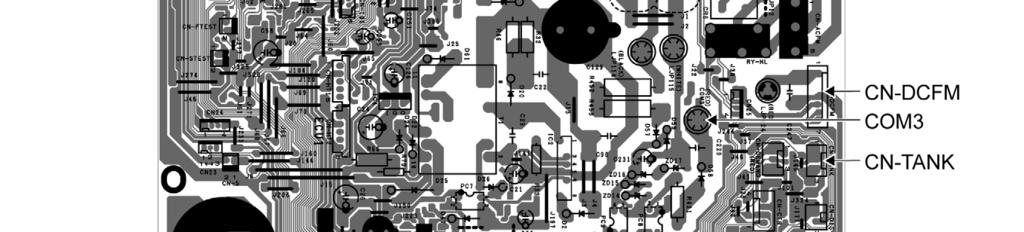
19 10.2 Outdoor Unit Main Printed Circuit Board 19
20 11. Installation Instruction Attached accessories No. Accessory part Qty. 1 Remote controller 1 2 Remote controller cable 1 3 Screw (M4 machine pitched - 30 mm) 3 4 Screw (M4 self tapping - 14 mm) 3 No. Accessory part Qty. 5 Drain elbow 1 6 Washer (for suspension fi tting) Flare insulator (for gas pipe / liquid pipe connection) Clamper (band) (for fl are & drain insulating connection) 2 4 No. Accessory part Qty. Drain Hose 9 (for unit & PVC pipe connection) L=131 1 Hose Band J (for drain hose connection) 1 Drain Hose insulation K (for drain pipe connection) 2 Clamper (Band) (for power supply cord) L * Be sure to fi x the power supply cord 1 with clamper (band). Required Materials Read the catalog and other technical materials and prepare the required materials. Applicable piping kit Applicable piping kit Gas Piping size Liquid CZ-3F5, 7BP 9.52 mm (3/8") 6.35 mm (1/4") CZ-4F5, 7, 10BP 12.7 mm (1/2") 6.35 mm (1/4") CZ-52F5, 7, 10BP mm (5/8") 6.35 mm (1/4") Pipe Size Reducer (CZ-MA1P) for Outdoor Multi connection Please refer to connect the piping in outdoor unit section Other Items to be Prepared (Locally Purchased) Installation parts you should purchase ( ) Sleeve ( ) Bushing-Sleeve ( ) Putty (Gum Type Sealer) ( ) Bend the pipe as closely on the wall as possible, but be careful that it doesn t break. Vinyl tape (Wide) ( ) Apply after carrying out a drainage test. To carry out the drainage test, remove the air fi lters and pour water into the heat exchanger. Product name Rigid PVC pipe Remarks VP20 (outer diameter ø26); also sockets, elbows and other parts as necessary Saddle ( ) Adhesive Insulation Indoor/outdoor connecting cable Hanging bolt related parts Insulation of piping connections Carry out insulation after checking for gas leaks and secure with vinyl tape. Indoor unit a Vinyl tape PVC adhesive For refrigerant piping insulation : foamed polyethylene with a thickness of 8 mm or more. For drain piping insulation : foamed polyethylene with a thickness of 10 mm or more. 4 x 1.5 mm 2 flexible cord, designation type IEC 57 (H05RN-F) Hanging bolts (M10) (4) and nuts (12), (when hanging the indoor unit) Attaching the remote controller to the wall Remote controller cable 2 Remote controller 1 Screws 3 or screws 4 Details refer to 3. INSTALLING THE INDOOR UNIT (Remote Control Installation) 100 mm or more 1000 mm or more 100 mm or more 300 mm or more Power supply cable ( ) Connection cable ( ) 1/4" Liquid side piping ( ) Gas side piping ( ) Additional drain hose ( ) b Outdoor unit IMPORTANT Begin the installation job from the Indoor Unit installation. It is advisable to avoid more than 2 blockage directions. For better ventilation & multiple-outdoor installation, please consult authorized dealer/ specialist. Or This illustration is for explanation purposes only. The indoor unit will actually face a different way. 20
21 11.1 Indoor Unit Selecting the Installation Location Take into consideration the following contents when creating the blueprint. Indoor unit installation location Do not install the unit in excessive oil fume area such as kitchen, workshop and etc. The location should be strong enough to support the main unit without vibration. There should not be any heat or steam source nearby. Drainage should be easy. Avoid locating the drain port close to ditches (domestic wastewater). Avoid locations above entrances and exits. Do not block the air intake and discharge passages. Select the location that enables the cool and warm air to spread out to the entire room. Locate the indoor unit at least 1 m or more away from a TV, radio, wireless appliance, antenna cable and fluorescent light, and 2 m or more away from a telephone. Recommended installation height for indoor unit shall be at least 2.5 m from floor. Remote controller 1 Install the remote controller cable at least 5 cm away from electric wires of other appliances to avoid miss-operation (electromagnetic noise). Upper case Lower case Remote control mounting location Allow sufficient space around the remote controller 1 as shown in the illustration at right. Install in a place which is away from direct sunlight and high humidity. Install in a flat surface to avoid warping of the remote controller. If installed to a wall with an uneven surface, damage to the LCD case or operation problems may result. Install in a place where the LCD can be easily seen for operation. (Standard height from the floor is 1.2 to 1.5 meters.) Avoid installing the remote controller cable near refrigerant pipes or drain pipes, else it will cause electrical shock or fire. 30 mm or more 30 mm or more Remote controller lower case 30 mm or more 30 mm or more To Drill a Hole in the Wall and Install a Sleeve of Piping 1 Insert the piping sleeve to the hole. 2 Fix the bushing to the sleeve. 3 Cut the sleeve until it extrudes about 15 mm from the wall. When the wall is hollow, be sure to use the sleeve for tube assembly to prevent pests from damaging the cables, e.g. mice biting the connection cable. 4 Finish by sealing the sleeve with putty or caulking compound at the final stage. Indoor Sleeve for tube assembly ø70 mm through hole Wall Outdoor 15 mm Bushing for tube assembly Approx. 5-7 mm Putty or caulking compound 21
22 Installing the Indoor Unit (Installation Embedded in the Ceiling) Preparation Before Installation Always provide sufficient entry and exit space to allow installation work, inspection and unit replacement. Waterproof the rear surface of the ceiling below the unit in consideration of water droplets forming and dropping. When cooling operation is performed for an extended period under the following conditions, water droplets may form and drop. Attach locally purchased insulation (foamed polyethylene with a thickness of 5 mm or more) to the outside of the indoor unit before installing into the ceiling to improve heat insulation. Locations with a dew point inside the ceiling of 23 C or more Kitchens and other locations that produce large amounts of heat and steam Locations where the inside of the ceiling serves as an outside air intake passage When installing into a ceiling, select the unit position and airflow direction that enable the cool and warm air to spread out to the whole room. Do not place objects that might obstruct the airflow within 1 m below the intake grill. Required Minimum Space for Installation and Service 824 (Suspension bolt pitch) Min. 200 or more Electrical component box Min. 200 or more 564 Inspection access 450 x 450 Refrigerant tubing Flange for air outlet duct Min. 650 or more Min. 20 or more Min. 100 mm or more for bottom air intake 200 Min. 20 or more *H=Min. 240 Ceiling H dimension means the minimum height of the unit installation space. Select H dimension such that a downward slope of at least 1/100 is ensured. Refer to Connecting the drain piping 22
23 Dimension of the Indoor Unit 640 Flange for air outlet duct (Suspension bolt pitch) (Flange for air outlet duct) 640 (160x4) 5-ø3.1(Hole) Suspension lug 27 Inspection access (450x450) (Field supply) Water inlet ø3.1(Hole) (Suspension bolt pitch) ø3.1(Hole) * Filter Uninstalled In Case of Bottom Intake 1 Remove the frame filter assy as shown in diagram 1 2 Remove cover plate as shown in diagram 1 3 Fix frame filter assy as shown in diagram 2 4 Fix cover plate as shown in diagram 2 with the dummy hole downward. Air discharge 1 2 Dummy hole Air intake Frame Filter Assy Cover plate Air discharge Cover plate Air intake Dummy hole Frame Filter Assy Fixing Frame Filter Assy Main unit In case of bottom side Filter Assy * Attach the frame fi lter assy to the main unit while pushing the tip of the latches in the direction of the arrow. In case of back side 23
24 Ceiling Opening Install inspection opening (450 mm x 450 mm) on the control box side where maintenance and inspection of the control box and drain pump are easy. Install another inspection opening (800 mm x 700 mm) also at the lower part of the unit. 700 Air discharge Air intake Allow view A Inspection access (Field supply) 800 A Ceiling Securing the Hanging Bolts Hanging bolt M10 Reinforced concrete Approx. 114 Insert hole-in anchor, etc. Ceiling surface Wooden of other structure (Hanging bolt pitch) Hanging bolt 40 t = 2 30 C channel Hanging fi xture Hanging bolt M10 Reinforcing materials (60 to 90 mm 2 ) Approx. 114 Roof beam Ceiling surface Secure the hanging bolts (M10, locally purchased) firmly in a manner capable of supporting the unit weight. Consult your construction or interior contractor for details on finishing the ceiling opening. Installing an Intake and Discharge Duct Type Ensure the range of unit external static pressure is not exceeded. Refer technical manual for the range of external static pressure setting. Connect the duct as shown. When attaching duct to the intake side, remove the product filter frame assy and replace with locally purchase intake-side flange by using flange by using 10 - Ø 3.1(hole) screws. Wrap the flange and duct connection area with aluminium tape or similar to prevent air leak. Flange (locally purchase) Connection screw (x10) Rectangular solic duct Main unit Flange Insulation material (locally purchased) Air inlet side Air outlet side When attaching a duct to the intake-side, be sure to attach an air filter inside the air passage on the intake-side. (Use an air filter with dust collecting efficiency at least 50% in a gravimetric technique.) 24
25 Installation into the Ceiling Attach the nuts and washers to the hanging bolts, then lift up and hook the main unit onto the hanging fixtures. Check if the unit is leveled using a level or a vinyl hose filled partially with water. Flat washer 6 Hanging bolt (M10) (locally purchased) Hexagonal nut (M10) (locally purchased) Level Remote Controller Installation 1 Remove the remote controller 1 lower case. (Insert a flat-tipped screw driver or similar tool 2 to 3 mm into one of the gaps at the bottom of the case, and twist to open. Refer to the illustration at right.) Be careful not to damage the lower case. 2 Do not remove the protective tape which is affixed to the upper case circuit board when remove the remote controller lower case. 3 Secure the lower case to an outlet box or wall. Refer to (A) or (B) instructions below depending on your choice of cable installation. 4 Be sure to use only the screws provided. 5 Do not over tighten the screws, as it may result in damage to the lower case. 6 Connect the indoor unit and the remote controller 1. (Refer to the illustration) 7 Insert firmly the connector of remote controller cable 2 to connector at control box of indoor unit. 8 Fix the green wire from remote controller cable 2 to the grounding location provided inside control board. Screw driver Gaps Upper case Lower case Control box Connector Screws 3 or Screws 4 Remote controller cable 2 Remote controller 1 25
26 A. IF REMOTE CONTROLLER CABLE IS EMBEDDED 1 Embed an outlet box (JIS C 8336) into the wall. Outlet box maybe purchased separately. Medium size square outlet box (obtain locally) Part No. DS3744 (Panasonic Co., Ltd.) or equivalent. 2 Secure the remote controller lower case to the outlet box with the two accessory screws 3. Make sure that the lower case is flat againts the wall at this time, with no bending. 3 Pass the remote controller cable 2 into the box. 4 Route the remote controller cable 2 inside the lower case through rear feeding-out direction. 5 Insert firmly the connector of remote controller cable 2 to connector (CON1) in the upper case circuit board. 6 Secure the remote controller upper case to the lower case with the tabs provided. When the wall is hollow, please be sure to use the sleeve for remote controller cable to prevent dangers caused by mice biting the cable. Upper case Upper tab Connector (CON1) Lower case Screws 3 Wall Remote controller cable 2 Remote controller cable 2 Rear feedingout position Lower case Tabs Upper case Connector (CON1) Upper case Lower tab Outlet box (JIS C 8336) Lower case B. IF REMOTE CONTROLLER CABLE IS EXPOSED 1 Install the remote controller lower case to the wall with the two accessory screws 4. 2 Fasten the screws properly until screw head is lower than the rib and reach the base of remote controller lower case to ensure they do not damage the PCB inside the remote controller 1. Rib Screws 4 Remote controller lower case Wall Remote controller cable 2 Upper case Upper tab Connector (CON1) Lower case Screws 4 Lower tab Wall 3 The feeding-out direction for the remote controller cable can be either via top, left or right side. 4 Use nipper to cut a notch at the upper case. (Select the intended feeding-out position) 5 Route the remote controller cable 2 inside the lower case in accordance with the intended feeding-out direction. (Refer to the illustration at below). 6 Insert firmly the connector of remote controller cable 2 to connector (CON1) in the upper case circuit board. (Refer to the illustration) 7 Secure the remote controller upper case to the lower case with the tabs provided. Remote controller Top feeding-out position cable 2 Notches Left feedingout position Lower case Tabs Connector (CON1) Upper case Right feeding-out position Upper case Lower case 26
27 Connecting the Drain Piping Lay the drain piping so as to ensure drainage. Use a locally purchased VP20 general rigid PVC pipe (outer diameter ø26) for the drain piping and firmly connect the indoor unit and the drain piping using supplied hose band to ensure that no leakage occurs. Drain piping located indoor should always be insulated by wrapping with locally purchased insulation (foamed polyethylene with a thickness of 10 mm or more). The drain piping should have a downward gradient (1/100 or more) and should be secured by using pipe hanging equipment to avoid creating hills or traps partway. Should there be any obstacle preventing the drain piping from being extended smoothly, the drain piping can be raised outside of the main unit as shown in the illustration below. Unit drain port Hose band 0 Hard PVC pipe (VP20) Rise Hill Drain hose 9 Do not use adhesive. Adhere with PVC adhesive. Trap Drain insulator K At least 1/ mm or less (not a downward gradient) Good 500 mm or less Strictly do not install and extend the drain piping from the main unit drain water outlet horizontally or upward or raised it 50 cm or more. Doing so may result in poor drainage or drain motor failure. Do not use drain hose bent at 90 angle. (The maximum permissible bend is 45.) Insulating the Refrigerant After the piping is connected, insulate. (Refer to the illustration) Clamper 8 Wrap firmly with vinyl tape, leaving no gaps. Unit side Wrap firmly with vinyl tape, leaving no gaps. Flare insulator 7 27
28 Connecting the Indoor/Outdoor Connection Cable Remove the control box cover and insert the connection cable into the control box. Check the color of the wires on the terminal board and secure them with screws. Secure the outer sheath of the connection cable with the cord clamp. Reattach the control box cover to its original position. Ensure the colour of wires of outdoor unit and the terminal Nos. are the same to the indoor s respectively. Earth wire shall be Yellow/Green (Y/G) in colour and longer than other AC wires for safety reason. WARNING This equipment must be properly earthed. When the wall is hollow, please be sure to use the sleeve for tube ass y to prevent dangers caused by mice biting the connection cable. Connection cable between indoor unit and outdoor unit should be approved polychloroprene sheathed 4 x 1.5 mm 2 flexible cord, designation type IEC 57 (H05RN-F) or heavier cord. Allowable connection cable length of each indoor unit shall be 30 m or less. o Ensure that the terminal numbers on the indoor unit are connected to the same terminal numbers on the outdoor unit by the right coloured wires as shown in the diagram. o Earth lead wire should be longer than the other lead wires as shown in the diagram for electrical safety purpose in case the cord slips out from the anchorage. o Secure the cable onto the control board with the holder (clamper). Earth wire (connection cable) DRAIN TEST switch Holder for connection cable Indoor/outdoor connection terminal FAN switch (SW2) Wire remote control connector Earth wire (remote control cable) Indoor/outdoor connection cable Terminals on the indoor unit Colour of wires Terminals on the outdoor unit
29 Wire Stripping and Connecting Requirement No loose strand when inserted 10 ± 1 mm Wire stripping Indoor/outdoor connection terminal board 5 mm or more Conductor fully inserted Conductor over inserted Conductor not fully inserted (gap between wires) ACCEPT PROHIBITED PROHIBITED Do not joint wires WARNING RISK OF FIRE JOINING OF WIRES MAY CAUSE OVERHEATING AND FIRE. OR OR OR Use complete wire without joining. Use approved socket and plug with earth pin. Wire connection in this area must follow to national wiring rules. 29
30 11.2 Outdoor Unit Selecting the Installation Location If an awning is built over the unit to prevent direct sunlight or rain, be careful that heat radiation from the condenser is not obstructed. There should not be any animal or plant which could be affected by hot air discharged. Keep the spaces indicated by arrows from wall, ceiling, fence or other obstacles. Do not place any obstacles which may cause a short circuit of the discharged air. If piping length is over the [piping length for additional gas], additional refrigerant should be added as shown in the table. Model E18***** Horse Power (HP) 2.0HP Gas 12.7 mm (1/2") Piping size Liquid 6.35 mm (1/4") Std. Length (m) Max. Elevation (m) Min. Piping Length (m) Max. Piping Length (m) Additional Refrigerant (g/m) Piping Length for add. gas (m) Example: For E18***** If the unit is installed at 12 m distance, the quantity of additional refrigerant should be 40 g... (12-10) m x 20 g/m = 40 g Install the Outdoor Unit At the best location, start installation according to Indoor-Outdoor Unit Installation Diagram. 1 Fix the unit on concrete or rigid frame firmly and horizontally by bolt nut (ø10 mm). 2 When installing at roof, please consider strong wind. Please fasten the installation stand firmly with bolt or nails. A B C Model A B C D E18**** 613 mm 130 mm 24 mm mm D Connect the Piping Connecting the Piping to Indoor Unit Please make flare after inserting flare nut (locate at joint portion of tube assembly) onto the copper pipe. (In case of using long piping) Connect the piping Align the center of piping and sufficiently tighten the flare nut with fingers. Further tighten the flare nut with torque wrench in specified torque as stated in the table. Do not overtighten, overtightening may cause gas leakage. Piping size Torque 6.35 mm (1/4") [18 N m (1.8 kgf m)] 9.52 mm (3/8") [42 N m (4.3 kgf m)] 12.7 mm (1/2") [55 N m (5.6 kgf m)] mm (5/8") [65 N m (6.6 kgf m)] mm (3/4") [100 N m (10.2 kgf m)] Connecting the Piping to Outdoor Unit Decide piping length and then cut by using pipe cutter. Remove burrs from cut edge. Make flare after inserting the flare nut (locate at valve) onto the copper pipe. Align center of piping to valve and then tighten with torque wrench to the specified torque as stated in the table. Spanner or Wrench Torque wrench 30
31 Connecting the Piping to Outdoor Multi Decide piping length and then cut by using pipe cutter. Remove burrs from cut edge. Make flare after inserting the flare nut (locate at valve) onto the copper pipe. Align center of piping to valve and then tighten with torque wrench to the specified torque as stated in the table. Hall union Auxiliary pipe (male side) Liquid side Flare Nut Connection pipe (female side) * For Gas side piping please refer table and diagram below CS-E18***** Outdoor Multi combination model CU-3E18***, CU-4E23*** CU-4E27***, CU-5E34*** Hall union Auxiliary pipe (male side) Packing Gas side Pipe size reducer (CZ-MA1P) Connection pipe (female side) Flare Nut * Kindly consult authorised dealer for connectivity validity Evacuation of the Equipment WHEN INSTALLING AN AIR CONDITIONER, BE SURE TO EVACUATE THE AIR INSIDE THE INDOOR UNIT AND PIPES in the following procedure. Indoor unit Liquid side Two-way valve Outdoor unit Close Gas side OPEN Three-way valve Close Lo Hi Vacuum pump CLOSE 1 Connect a charging hose with a push pin to the Low side of a charging set and the service port of the 3-way valve. o Be sure to connect the end of the charging hose with the push pin to the service port. 2 Connect the center hose of the charging set to a vacuum pump. 3 Turn on the power switch of the vacuum pump and make sure that the needle in the gauge moves from 0 cmhg (0 MPa) to -76 cmhg (-0.1 MPa). Then evacuate the air approximately ten minutes. 4 Close the Low side valve of the charging set and turn off the vacuum pump. Make sure that the needle in the gauge does not move after approximately five minutes. Note: BE SURE TO TAKE THIS PROCEDURE IN ORDER TO AVOID REFRIGERANT GAS LEAKAGE. 5 Disconnect the charging hose from the vacuum pump and from the service port of the 3-way valve. 6 Tighten the service port caps of the 3-way valve at a torque of 18 N m with a torque wrench. 7 Remove the valve caps of both of the 2-way valve and 3-way valve. Position both of the valves to OPEN using a hexagonal wrench (4 mm). 8 Mount valve caps onto the 2-way valve and the 3-way valve. o Be sure to check for gas leakage. If gauge needle does not move from 0 cmhg (0 MPa) to -76 cmhg (-0.1 MPa), in step 3 above take the following measure: - If the leak stops when the piping connections are tightened further, continue working from step 3. - If the leak does not stop when the connections are retightened, repair location of leak. - Do not release refrigerant during piping work for installation and reinstallation. - Take care of the liquid refrigerant, it may cause frostbite. 31
32 Connect the cable to the Outdoor Unit (FOR DETAIL REFER TO WIRING DIAGRAM AT UNIT) 1 Remove the control board cover from the unit by loosening the screw. 2 Cable connection to the power supply through Isolating Devices (Disconnecting means). o Connect approved type polychloroprene sheathed power supply cord 3 x 2.5 mm 2 type designation IEC 57 or heavier cord to the terminal board, and connect the others end of the cord to Isolating Devices (Disconnecting means). 3 Connection cable between indoor unit and outdoor unit shall be approved polychloroprene sheathed 4 x 1.5 mm 2 flexible cord, type designation IEC 57 or heavier cord. Allowable connection cable length of each indoor unit shall be 30 m or less. 4 Connect the power supply cord and connection cable between indoor unit and outdoor unit according to the diagram below. Terminals on the indoor unit Colour of wires (connection cable) Terminals on the outdoor unit L N (Power supply cord) Terminals on the isolating devices (Disconnecting means) (L) (N) Secure the power supply cord and connection cable onto the control board with the holder. 6 Attach the control board cover back to the original position with screw. 7 For wire stripping and connection requirement, refer to instruction of indoor unit. Earth Wire longer than others AC wires for safety reason Power supply cord Isolating Devices WARNING Terminal Board Earth Wire longer than others AC wires for safety reason Holder Indoor and outdoor connection cable Indoor Unit This equipment must be properly earthed. Note: Isolating Devices (Disconnecting means) should have minimum 3.0 mm contact gap. Earth wire shall be Yellow/Green (Y/G) in colour and longer than other AC wires for safety reason Piping Insulation 1 Please carry out insulation at pipe connection portion as mentioned in Indoor/Outdoor Unit Installation Diagram. Please wrap the insulated piping end to prevent water from going inside the piping. 2 If drain hose or connecting piping is in the room (where dew may form), please increase the insulation by using POLY-E FOAM with thickness 8 mm or above Cutting and Flaring the Piping 1 Please cut using pipe cutter and then remove the burrs. 2 Remove the burrs by using reamer. If burrs is not removed, gas leakage may be caused. Turn the piping end down to avoid the metal powder entering the pipe. 3 Please make flare after inserting the flare nut onto the copper pipes. 1. To cut Pipe Reamer Bar Handle Yoke Core Point down Clamp handle Red arrow mark 2. To remove burrs 3. To fl are Bar mm Copper pipe Improper flaring Inclined Surface Cracked Uneven damaged thickness When properly fl ared, the internal surface of the flare will evenly shine and be of even thickness. Since the fl are part comes into contact with the connections, carefully check the flare finish. 32
33 Switching the High State Switch (SW2) To increase the air volume, open the control box and on the control board, switch the FAN switch (SW2) to HI. See the diagram for Connecting the Indoor/Outdoor Connection Cable. Note: Enabling Long-range Remote Control To maintain EMC emission limits, cabling interconnecting the HA terminal and subsequent opto-coupler, must be no more than 1.9 m length. Loop four turns of this cable through a suitable small EMC ferrite toroid, and protect with a short length of large diameter heat-shrink tube. There is no similar length limit for cable following on from the opto-coupler isolation. CHECK THE DRAINAGE Check after connecting the power supply. Pour approximately 600 cc of water into the drain pan of the main unit using a squeeze bottle, etc. Press the drain test run switch on the control board in the control box to start the drain motor and check whether the water drains normally. (The drain motor operates for approximately 5 minutes and then stops automatically.) (See the diagram for Connecting the Indoor/Outdoor Connection Cable.) Heat exchanger Drain pan Squeeze bottle Approximately 600 cc of water DISPOSAL OF OUTDOOR UNIT DRAIN WATER If a drain elbow is used, the unit should be placed on a stand which is taller than 30 mm. If the unit is used in an area where temperature falls below 0 C for 2 or 3 days in succession, it is recommended not to use a drain elbow, for the drain water freezes and the fan will not rotate. Drain elbow 5 Hose Install the hose at an angle so that the water smoothly flows out. 33
34 12. Operation and Control 12.1 Basic Function Inverter control, which equipped with a microcomputer in determining the most suitable operating mode as time passes, automatically adjusts output power for maximum comfort always. In order to achieve the suitable operating mode, the microcomputer maintains the set temperature by measuring the temperature of the environment and performing temperature shifting. The compressor at outdoor unit is operating following the frequency instructed by the microcomputer at indoor unit that judging the condition according to internal setting temperature and intake air temperature Internal Setting Temperature Once the operation starts, remote control setting temperature will be taken as base value for temperature shifting processes. These shifting processes are depending on the air conditioner settings and the operation environment. The final shifted value will be used as internal setting temperature and it is updated continuously whenever the electrical power is supplied to the unit. Remote Control Setting Temperature 16ºC ~ 30ºC Auto Operation Mode Shifting Setting Temperature Limit Checking (Min: 16ºC; Max: 30ºC) Outdoor Air Temperature Shifting Powerful Mode Shifting Fan Speed Shifting Start-Up Shifting Setting Temperature Limit Checking (Min: 16ºC; Max: 30ºC) Internal Setting Temperature Cooling Operation Thermostat control Compressor is OFF when Intake Air Temperature - Internal Setting Temperature < -2.0 C continue for 3 minutes. Compressor is ON after waiting for 3 minutes, if the Intake Air Temperature - Internal Setting Temperature > Compressor OFF point Soft Dry Operation Thermostat control Compressor is OFF when Intake Air Temperature - Internal Setting Temperate < -2.0 C continue for 3 minutes. Compressor is ON after waiting for 3 minutes, if the Intake Air Temperature - Internal Setting Temperature > Compressor OFF point. 34
35 Heating Operation Thermostat control Compressor is OFF when Intake Air Temperature - Internal Setting Temperate > +2.0 C. Compressor is ON after waiting for 3 minutes, if the Intake Air Temperature - Internal Setting Temperature < Compressor OFF point Automatic Operation This mode can be set using remote control and the operation is decided by remote control setting temperature, remote control operation mode and indoor intake air temperature. During operation mode judgment, indoor fan motor (with speed of Lo-) is running for 30 seconds to detect the indoor intake air temperature. Every 10 minutes, the indoor temperature is judged. For the 1st judgment o If indoor intake temperature - remote control setting temperature 2 C, COOL mode is decided. o If -2 C indoor intake temperature - remote control setting temperature < 2 C, DRY mode is decided. o If indoor intake temperature - remote control setting temperature < -2 C, HEAT mode is decided. Heat Dry Cool For the 2nd judgment onwards o If indoor intake temperature - remote control setting temperature 3 C, if previous operate in DRY mode, then continue in DRY mode. Otherwise COOL mode is decided. o If -2 C indoor intake temperature - remote control setting temperature < 3 C, maintain with previous mode. o If indoor intake temperature - remote control setting temperature < -2 C, HEAT mode is decided. Heat Maintain Cool/Dry Indoor Fan Motor Operation A. Basic Rotation Speed (rpm) i. Manual Fan Speed [Cooling, Dry] Fan motor s number of rotation is determined according to remote control setting. Remote Control O O O O O Tab (rpm) Hi Me+ Me Me- Lo [Heating] Fan motor s number of rotation is determined according to remote control setting. Remote Control O O O O O Tab (rpm) Shi Me+ Me Me- Lo ii. Auto Fan Speed [Cooling, Dry] According to room temperature and setting temperature, indoor fan speed is determined automatically. 35
36 The indoor fan will operate according to pattern below. Fan Speed Higher Medium Lower [1 pattern : 10 s] a b c d e f g h a b [Heating] According to indoor pipe temperature, automatic heating fan speed is determined as follows. RPM Increased 39ºC RPM Maintain 35ºC RPM Reduced 19ºC OFF 16ºC Indoor Pipe Temp. B. Feedback control Immediately after the fan motor started, feedback control is performed once every second. During fan motor on, if fan motor feedback 2550 rpm or < 50 rpm continue for 10 seconds, then fan motor error counter increase, fan motor is then stop and restart. If the fan motor counter becomes 7 times, then H19 - fan motor error is detected. Operation stops and cannot on back Outdoor Fan Motor Operation Outdoor fan motor is operated with 15 fan speed. It starts when compressor starts operation and it stops 30 seconds after compressor stops operation. Compressor: ON OFF ON Outdoor Fan: ON Fan Speed 30 sec OFF ON 36
37 12.2 Quiet Operation (Cooling Mode/Cooling Area of Soft Dry Mode) A. Purpose To provide quiet cooling operation compare to normal operation. B. Control condition a. Quiet operation start condition When quiet button at remote control is pressed. Quiet LED illuminates. b. Quiet operation stop condition 1 When one of the following conditions is satisfied, quiet operation stops: a. Powerful button is pressed. b. Stop by OFF/ON switch. c. Timer off activates. d. Quiet button is pressed again. 2 When quiet operation is stopped, operation is shifted to normal operation with previous setting. 3 When fan speed is changed, quiet operation is shifted to quiet operation of the new fan speed. 4 When operation mode is changed, quiet operation is shifted to quiet operation of the new mode. 5 During quiet operation, if timer on activates, quiet operation maintains. 6 After off, when on back, quiet operation is not memorised. C. Control contents 1 Auto fan speed is changed from normal setting to quiet setting of respective fan speed. This is to reduce sound of Hi, Me, Lo for 3dB. 2 Manual fan speed for quiet operation is 1 step from setting fan speed. 3 Compressor frequency reduced Quiet operation (Heating) A. Purpose To provide quiet heating operation compare to normal operation. B. Control condition a. Quiet operation start condition When quiet button at remote control is pressed. Quiet LED illuminates. b. Quiet operation stop condition 1 When one of the following conditions is satisfied, quiet operation stops: a. Powerful button is pressed. b. Stop by OFF/ON switch. c. Timer off activates. d. Quiet button is pressed again. 2 When quiet operation is stopped, operation is shifted to normal operation with previous setting. 3 When fan speed is changed, quiet operation is shifted to quiet operation of the new fan speed. 4 When operation mode is changed, quiet operation is shifted to quiet operation of the new mode, except fan only mode. 5 During quiet operation, if timer on activates, quiet operation maintains. 6 After off, when on back, quiet operation is not memorised. C. Control contents a. Fan Speed Auto Indoor FM RPM depends on pipe temperature sensor of indoor heat exchanger. Auto fan speed is changed from normal setting to quiet setting of respective fan speed. This is to reduce sound of Hi, Me, Lo for 3dB. b. Fan Speed Manual Manual fan speed for quiet operation is - 1 step from setting fan speed. c. Compressor frequency reduced. 37
38 12.3 Powerful Mode Operation When the powerful mode is selected, the internal setting temperature will shift higher up to +6.0 C (for Heating) or lower up to 4 C (for Cooling/Soft Dry) than remote control setting temperature for 20 minutes to achieve the setting temperature quickly Timer Control ON Timer Control ON timer can be set using remote control, the unit with timer set will start operate earlier than the setting time. This is to provide a comfortable environment when reaching the set ON time. 60 minutes before the set time, indoor (at fan speed of Lo-) and outdoor fan motor start operate for 30 seconds to determine the indoor intake air temperature and outdoor air temperature in order to judge the operation starting time. From the above judgment, the decided operation will start operate earlier than the set time as shown below. Indoor intake air temperature (ºC) min Indoor intake air temperature (ºC) min 10 min 30 min min 35 min (ºC) Outdoor air temperature (ºC) 0 5 (ºC) Outdoor air temperature (ºC) Cooling/Soft Dry Heating OFF Timer Control OFF timer can be set using remote control, the unit with timer set will stop operate at set time Auto Restart Control 1 When the power supply is cut off during the operation of air conditioner, the compressor will re-operate within three to four minutes (there are 10 patterns between 2 minutes 58 seconds and 3 minutes 52 seconds to be selected randomly) after power supply resumes. 2 This type of control is not applicable during ON/OFF Timer setting. 3 This control can be omitted by open the circuit of JP10 at indoor unit printed board Indication Panel LED Color Light ON Light OFF OFF/ON Operation Green Operation ON Operation OFF Note: If OFF/ON operation LED is OFF and OFF indicator does not shown on remote control display, there is an abnormality operation occurs. 38
39 13. Protection Control 13.1 Protection Control For All Operations Restart Control (Time Delay Safety Control) The Compressor will not turn on within 3 minutes from the moment operation stops, although the unit is turned on again by pressing OFF/ON button at remote control within this period. This control is not applicable if the power supply is cut off and on again. This phenomenon is to balance the pressure inside the refrigerant cycle Seconds Forced Operation Once the air conditioner is turned on, the compressor will not stop within 30 seconds in a normal operation although the intake air temperature has reached the thermo-off temperature. However, force stop by pressing the OFF/ON button at the remote control is permitted or the Auto OFF/ON button at indoor unit. The reason for the compressor to force operation for minimum 30 seconds is to allow the refrigerant oil run in a full cycle and return back to the outdoor unit Total Running Current Control 1 When the outdoor unit total running current (AC) exceeds X value, the frequency instructed for compressor operation will be decreased. 2 If the running current does not exceed X value for five seconds, the frequency instructed will be increased. 3 However, if total outdoor unit running current exceeds Y value, compressor will be stopped immediately for 3 minutes. E18RD3EAW Operation mode X (A) Y (A) Cooling/Soft Dry (A) Cooling/Soft Dry (B/C) Heating The first 30 minutes of cooling operation, (A) will be applied. 102ºC (C) 39ºC (B) 101ºC Outdoor air temperature (A) 38ºC 39
40 IPM (Power transistor) Prevention Control Overheating Prevention Control 1 When the IPM temperature rises to 120 C, compressor operation will stop immediately. 2 Compressor operation restarts after three minutes the temperature decreases to 110 C. DC Peak Current Control 1 When electric current to IPM exceeds set value of 30.0 ± 5.0 A, the compressor will stop operate. Then, operation will restart after three minutes. 2 If the set value is exceeded again more than 30 seconds after the compressor starts, the operation will restart after two minutes. 3 If the set value is exceeded again within 30 seconds after the compressor starts, the operation will restart after one minute. If this condition repeats continuously for seven times, all indoor and outdoor relays will be cut off Compressor Overheating Prevention Control Instructed frequency for compressor operation will be regulated by compressor top temperature. The changes of frequency are as below figure. If compressor temperature exceeds 107 C, compressor will be stop, occurs 4 times per 20 minutes, timer LED will be blinking ( F97 is to be confirmed). 107ºC 103ºC 100ºC Compressor = OFF Compressor Frequency Reduce Compressor Frequency Maintain Free 92ºC 91ºC 90ºC Comp. top temperature 13.2 Protection Control For Cooling & Soft Dry Operation Outdoor Air Temperature Control The compressor operating frequency is regulated in accordance to the outdoor air temperature as shown in the diagram below. This control will begin 1 minute after the compressor starts. Compressor frequency will adjust base on Outdoor Air Temperature. 25ºC Free Limited frequency 22ºC Outdoor Air Temperature 40
41 Cooling Overload Control i. Pipe temperature limitation/restriction Detects the Outdoor pipe temperature and carry out below restriction/limitation (Limit the compressor Operation frequency) The compressor stop if outdoor pipe temperature exceeds 63 C. If the compressor stops 4 times in 20 minutes, Timer LED blinking (F95: outdoor high pressure rise protection) Dew Prevention Control 1 1 To prevent dew formation at indoor unit discharge area. 2 This control activated if: o Outdoor air temperature and Indoor pipe temperature judgment by microcontroller if fulfilled. o When Cooling or Dry mode is operated more than 20 minutes or more. 3 This control stopped if: o Compressor stopped. o Remote control setting changed. (fan speed / temperature) o Outdoor air temperature and indoor intake temperature changed Dew Prevention Control 2 1 To prevent dew formation at indoor unit discharge area. 2 This control starts if all conditions continue for 20 minutes: o Operated with Cooling or Soft Dry Mode. o Indoor intake temperature is between 25 C and 29 C. o Outdoor air temperature is less than 30 C. o Quiet Lo fan speed. 3 This control stopped if: o When receive air swing change signal from Remote Control Freeze Prevention Control 1 When indoor heat exchanger temperature is lower than 0 C continuously for six minutes, compressor will stop operating. 2 Compressor will resume its operation 3 minutes after the indoor heat exchanger is higher than 5 C. 3 At the same time, indoor fan speed will be higher than during its normal operation. 4 If indoor heat exchanger temperature is higher than 13 C, the fan speed will return to its normal operation. 41
42 13.3 Protection Control For Heating Operation Intake Air Temperature Control Compressor will operate at maximum frequency if below conditions occur: 1 When the indoor intake air temperature is 30 C or above Outdoor Air Temperature Control The maximum current value is regulated when the outdoor air temperature rises above 14 C in order to avoid compressor overloading Overload Protection Control The compressor operating frequency is regulated in accordance to indoor heat exchanger temperature as shown in below figures. If the heat exchanger temperature exceeds 60 C, compressor will stop. 60ºC 55ºC 49ºC OFF Frequency Reduced Frequency Limited Free 46ºC Cold Draught Operation When indoor pipe temperature is low, cold draught operation start where indoor fan speed will be reduced Deice Operation When outdoor pipe temperature and outdoor temperature is low, deice operation start where indoor fan motor and outdoor fan motor stop and operation LED blinks Drain Pump Control This unit has built-in with drain pump. Control content During COOL/DRY mode. o During COOL/DRY mode, drain pump starts 10 seconds after indoor fan motor starts. o The drain pump turns ON and turns OFF periodically. (ON or OFF duration depends on room temperature). After COOL/DRY mode, when unit turns OFF (power standby) or changes to HEAT mode. o The drain pump turns ON for 60 seconds immediately. Error judgment o When float switch detects ON signal continuously for 2 minutes 30 seconds, error code H21 are shown. o When float switch ON has operated 2 times within 20 minutes, error code H35 are shown. 42
43 Pump Down Operation By CN-S A convenience method to activate pump down operation. Control start condition: o During power standby condition, short CN-S continuously between 1 second and 10 seconds. Control stop condition: o 480 seconds after pump down operation starts. o CN-S is shorted again during pump down operation. 43
 The Test Run operation will be activated by short-circuiting CN-S (Pin 1 & 2) at outdoor")
44 14. Servicing Mode 14.1 TEST RUN OPERATION (FOR PUMP DOWN/SERVICING PURPOSE) The Test Run operation will be activated by short-circuiting CN-S (Pin 1 & 2) at outdoor unit PCB after power supplied to outdoor unit terminal 1 and 2. The unit forced to run rated frequency cooling operation mode. 44
45 15. Troubleshooting Guide 15.1 Refrigeration Cycle System In order to diagnose malfunctions, make sure that there are no electrical problems before inspecting the refrigeration cycle. Such problems include insufficient insulation, problem with the power source, malfunction of a compressor and a fan. The normal outlet air temperature and pressure of the refrigeration cycle depends on various conditions, the standard values for them are shown in the table on the right. Normal Pressure and Outlet Air Temperature (Standard) Gas pressure MPa (kg/cm 2 G) Outlet air temperature ( C) Cooling Mode 0.9 ~ 1.2 (9 ~ 12) 12 ~ 16 Heating Mode 2.3 ~ 2.9 (23 ~ 29) 36 ~ 45 *Condition: Indoor fan speed; High Outdoor temperature 35 C at cooling mode and 7 C at heating mode Compressor operates at rated frequency Difference in the intake and outlet air temperatures More than 8 C (15 minutes after an operation is started.) at cooling mode. Above 14 C (15 minutes after an operation is started.) at heating mode. Normal Measuring the air temperature difference Less than 8 C at the cooling mode Less than 14 C at the heating mode Value of electric current during operation Higher than specified Dusty condenser preventing heat radiation Measuring electric current during operation Excessive amount of refrigerant Lower than specified Gas side pressure Cooling Mode High Inefficient compressor Measuring gas side pressure Low Insufficient refrigerant Heating Mode Low Low Low Clogged strainer or capillary tube Inefficient compressor Insufficient refrigerant Low Clogged strainer or capillary tube 45
46 15.2 Relationship Between the Condition of the Air Conditioner and Pressure and Electric Current Condition of the air conditioner Low Pressure Cooling Mode High Pressure Electric current during operation Low Pressure Heating Mode High Pressure Electric current during operation Insufficient refrigerant (gas leakage) Clogged capillary tube or Strainer Short circuit in the indoor unit Heat radiation deficiency of the outdoor unit Inefficient compression Carry out the measurement of pressure, electric current, and temperature fifteen minutes after an operation is started. 46
47 15.3 Breakdown Self Diagnosis Function Self Diagnosis Function (Three Digits Alphanumeric Code) Once abnormality has occurred during operation, the unit will stop its operation, and OFF/ON operation LED OFF. OFF indicator does not shown on remote control display. In operation after breakdown repair, the last error code abnormality will be stored in EEPROM. To make a diagnosis 1 OFF/ON operation LED OFF and the unit automatically stops the operation, but the OFF indicator does not shown. 2 Press CHECK button continuously for 5 seconds will be displayed on the remote controller display. 4 Press timer or button on the remote control. The error code H00 (no abnormality) will be displayed. 5 Every press of the button ( or ) will increase the error code number. 6 When the displayed error code matches the unit's error code, OFF/ON operation LED will be ON continuously. 7 The breakdown diagnosis mode will be cancelled by pressing CHECK button continuously for 5 seconds or wait for 30 seconds. AC Reset button When AC Reset button is pressed, the error code will be reset so that the unit will be able to operate and recheck if any error occurred. OFF Indicator Operation LED TIMER/CLOCK MODE UP OFF / ON SELECT FAN SPEED MODE OFF/ON DOWN SET AIR SWING QUIET/ POWERFUL TEMP CLOCK CANCEL AC RC CHECK RESET Check Button To display memorized error status: 1 Turn ON the power supply. 2 Press CHECK button continuously for 5 seconds will be displayed on the remote controller display. 4 Press timer or button on the remote control. The error code "H00" (no abnormality) will be displayed. 5 Every press of the button ( or ) will increase the error code number. 6 When the displayed error code matches the unit's error code, OFF/ON operation LED will be ON continuously. 7 The breakdown diagnosis mode will be cancelled by pressing CHECK button continuously for 5 seconds or wait for 30 seconds. 47
48 15.4 Error Codes Table Diagnosis display Abnormality / Protection control Abnormality Judgment Emergency Operation Primary location to verify H00 No abnormality detected Normal operation H11 Indoor / outdoor abnormal communication > 1 min. after starting operation Indoor fan operation only Internal / external cable connections Indoor / Outdoor PCB H12 Connection capability rank abnormal H14 H15 Indoor intake air temperature sensor abnormality Outdoor compressor temperature sensor abnormality Continue for 5 sec. Continue for 5 sec. H16 Outdoor Current Transformer open circuit H19 Indoor fan motor mechanism lock Intake air temperature sensor (defective or disconnected) Compressor temperature sensor (defective or disconnected) Outdoor PCB IPM (Power transistor) module Indoor PCB Fan motor H21 Indoor float switch operation abnormal H23 H24 H27 Indoor heat exchanger temperature sensor 1 abnormality Indoor heat exchanger temperature sensor 2 abnormality Outdoor air temperature sensor abnormality Continue for 5 sec. Continue for 5 sec. Continue for 5 sec. O (Cooling only) O Heat exchanger temperature sensor 1 (defective or disconnected) Heat exchanger temperature sensor 2 (defective or disconnected) Outdoor temperature sensor (defective or disconnected) H28 Outdoor heat exchanger temperature sensor abnormality Continue for 5 sec. O Outdoor heat exchanger temperature sensor (defective or disconnected) H30 H32 H34 H35 Discharge temperature sensor abnormality Outdoor heat exchanger temperature sensor 2 abnormality Outdoor heat sink temperature sensor abnormality Indoor drain water adverse current abnormal Continue for 5 sec. Discharge temperature sensor Continue for 5 sec. Continue for 2 sec. H36 Gas pipe temperature sensor abnormality Continue for 5 sec. H37 H39 H41 H97 Outdoor liquid pipe temperature sensor abnormality Abnormal indoor operating unit or standby units Wiring or piping connection abnormality Outdoor Fan Motor lock abnormality 48 Discharge pipe temperature sensor (defective or disconnected). Outdoor heat sink temperature sensor (defective or disconnected). Continue for 2 sec. Gas pipe temperature sensor (defective or disconnected). Outdoor liquid pipe temperature sensor (defective or disconnected). 3 minutes after compressor start up 2 times occurrence within 30 minutes H98 Indoor high pressure protection H99 F11 F17 F90 F91 F93 F95 F96 F97 Indoor heat exchanger anti-freezeing protection Cooling / Heating cycle changeover abnormality Indoor unit freezing error PFC control Refrigeration cycle abnormality Outdoor compressor abnormal revolution Cool high pressure protection IPM (power transistor) overheating protection Outdoor compressor overheating protection 4 times occurrence within 30 minutes 3 times occurrence within 30 minutes 4 times occurrence within 10 minutes 2 times occurrence within 20 minutes 4 times occurrence within 20 minutes 4 times occurrence within 20 minutes 4 times occurrence within 20 minutes Outdoor PCB Outdoor Fan Motor Air filter dirty Air circulation short circuit Insufficient refrigerant Air filter dirty 4-way valve V-coil Expansion valve leakage Indoor unit pipe temperature sensor (check for changes in characteristics and check its resistance) Voltage at PFC No refrigerant (3-way valve is closed) Outdoor compressor Outdoor refrigerant circuit Excess refrigerant Improper heat radiation IPM (Power transistor) Insufficient refrigerant Compressor
49 Diagnosis display F98 F99 Abnormality / Protection control Total running current protection Outdoor Direct Current (DC) peak detection Abnormality Judgment 3 times occurrence within 20 minutes 7 times occurrence continuously Emergency Operation Primary location to verify Excess refrigerant Improper heat radiation Outdoor PCB IPM (Power transistor) Compressor Note: O - Frequency measured and fan speed fixed. The memory data of error code is erased when the power supply is cut off, or press the Auto Switch until beep sound heard following by pressing the CHECK button at Remote Control. Although operation forced to stop when abnormality detected, emergency operation is possible for certain errors (refer to Error Codes Table) by using Remote Control or Auto Switch at indoor unit. However, the Remote Control signal receiving sound is changed from one beep to four beep sounds. 49
50 15.5 Self-diagnosis Method H11 (Indoor/Outdoor Abnormal Communication) Malfunction Decision Conditions During startup and operation of cooling and heating, the data received from outdoor unit in indoor unit signal transmission is checked whether it is normal. Malfunction Caused Faulty indoor unit PCB. Faulty outdoor unit PCB. Indoor unit-outdoor unit signal transmission error due to wiring error. Indoor unit-outdoor unit signal transmission error due to breaking of wire in the connection wires between the indoor and outdoor units. Troubleshooting When abnormality indication starts again Measure the AC voltage at terminal 1 & 2 of outdoor unit terminal board Caution For safety reason and to prevent component breakdown, always switch off the power before remove and connect the component. Is the measured voltage 230/240V? Measure the DC voltage at terminal 2 & 3 (communication terminals) of outdoor unit terminal board AC power supply abnormal fluctuation Is the measured DC voltage fluctuate between 10~70V? Measure the AC voltage at terminal 1 & 2 of indoor unit terminal board Defect in communication circuitry of outdoor unit PCB Replace the PCB Is the measured voltage 230/240V? Measure the DC voltage at terminal 2 & 3 of indoor unit terminal board Improper connection at terminals indoor/outdoor Check indoor/outdoor connecting cable Is the measured DC voltage fluctuate between 10~70V? Improper connection at terminals indoor/outdoor Check indoor/outdoor connecting cable Defect in receiver/transmitter module of the communication circuitry in indoor unit PCB Replace the indoor unit PCB 50
51 H12 (Indoor/Outdoor Capacity Rank Mismatched) Malfunction Decision Conditions During startup, error code appears when different types of indoor and outdoor units are interconnected. Malfunction Caused Wrong models interconnected. Wrong indoor unit or outdoor unit PCBs mounted. Indoor unit or outdoor unit PCBs defective. Indoor-outdoor unit signal transmission error due to wrong wiring. Indoor-outdoor unit signal transmission error due to breaking of wire 3 in the connection wires between the indoor and outdoor units. Troubleshooting When abnormality indication starts again Check the indoor and outdoor unit connection wires Caution For safety reason and to prevent component breakdown, always switch off the power before remove and connect the component. Is there any wiring error? Correct the indoor-outdoor units connection wires Check indoor and outdoor units model number. Is indoor unit and outdoor unit model numbers matched? Match the compatible model(s) Check the spare part numbers of the indoor and outdoor unit PCBs and compare with their Part Lists Matched compatibility? Change for the specified indoor or outdoor unit PCB Replace the indoor and outdoor unit PCBs 51
52 H14 (Indoor Intake Air Temperature Sensor Abnormality) Malfunction Decision Conditions During startup and operation of cooling and heating, the temperatures detected by the indoor intake air temperature sensor are used to determine sensor errors. Malfunction Caused Faulty connector connection. Faulty sensor. Faulty PCB. Troubleshooting When abnormality indication starts again Check the connector connection: Turn off the power Check the connector connection Caution For safety reason and to prevent component breakdown, always switch off the power before remove and connect the component. Is the connector connection normal? Check the indoor intake air temperature sensor: Plug out connector from t he indoor unit PCB Measure the resistance of the indoor intake air temperature sensor Connector poor contact Correct the connection Is the measured resistance of the indoor intake air temperature sensor matches the value specified in its characteristic chart? Defect in indoor intake air tempeature sensor Replace the indoor intake air temperature sensor Defect in indoor unit PCB Replace the indoor unit PCB Sensor (Thermistor) Characteristics 1 Pipe temp. Sensor 2 Intake Air Temp. Sensor 50 Resistance (kω) Temperature (ºC) 52
53 H15 (Compressor Temperature Sensor Abnormality) Malfunction Decision Conditions During startup and operation of cooling and heating, the temperatures detected by the outdoor compressor temperature sensor are used to determine sensor errors. Malfunction Caused Faulty connector connection. Faulty sensor. Faulty PCB. Troubleshooting When abnormality indication starts again Check the connector connection: Turn off the power Check the connector connection Caution For safety reason and to prevent component breakdown, always switch off the power before remove and connect the component. Is the connector connection normal? Check the outdoor compressor temperature sensor: Plug out connector from t he outdoor unit PCB Measure the resistance of the outdoor compressor temperature sensor Connector poor contact Correct the connection Is the measured resistance of the outdoor compressor temperature sensor matches the value specified in its characteristic chart? Defect in outdoor compressor temperature sensor Replace the outdoor compressor temperature sensor Defect in outdoor unit PCB Replace the outdoor unit PCB 70 Compressor Temp. Sensor (Thermistor) Characteristics Resistance (kω) Temperature ( o C) 53
54 H16 (Outdoor Current Transformer) Malfunction Decision Conditions An input current, detected by Current Transformer CT, is below threshold value when the compressor is operating at certain frequency value for 3 minutes. Malfunction Caused Lack of gas Broken CT (current transformer) Broken Outdoor PCB Troubleshooting When abnormality indication starts again Refer to Service Manual Technical Graph for Temp vs Current and Pressure Caution For safety reason and to prevent component breakdown, always switch off the power before remove and connect the component. Suction pressure and running current is normal In forced cooling, check suction pressure versus running current Running current is much too low and suction pressure is much too high Check & replace defected CT Running current and suction is very low Compressor Lack Compression Replace Compressor Check for gas leaking source; Repair or replace defected part(s) Capillary tube/expansion valve blockage; Replace defected part(s) 54
55 H19 (Indoor Fan Motor DC Motor Mechanism Locked) Malfunction Decision Conditions The rotation speed detected by the Hall IC during fan motor operation is used to determine abnormal fan motor (feedback of rotation > 2550 rpm or < 50 rpm) Malfunction Caused Operation stops due to short circuit inside the fan motor winding. Operation stops due to breaking of wire inside the fan motor. Operation stops due to breaking of fan motor lead wires. Operation stops due to Hall IC malfunction. Operation error due to faulty indoor unit PCB. Troubleshooting When abnormality indication starts again Turn off power supply and rotate fan by hand Caution For safety reason and to prevent component breakdown, always switch off the power before remove and connect the component. Does fan rotate smoothly? Replace fan motor Turn power supply on and operate fan. Does it rotate? Stop fan motor Turn off power supply and disconnect fan motor connector, then turn power on. Check the rotation feedback output from fan motor. Check the output of fan motor from indoor PCB Rotate the fan motor by hand, is the rotation feedback voltage 15Vdc (pin 7 & 4) generated? Is the motor power supply voltage ~325Vdc (pin 1 & 4) generated? Is the motor control voltage 15Vdc (pin 5 & 4) generated? Operate the fan, is the rotation command voltage 1~5Vdc (pin 6 & 4) generated? Replace indoor PCB Replace fan motor 55
56 H23 (Indoor Pipe Temperature Sensor Abnormality) Malfunction Decision Conditions During startup and operation of cooling and heating, the temperatures detected by the indoor heat exchanger temperature sensor are used to determine sensor errors. Malfunction Caused Faulty connector connection. Faulty sensor. Faulty PCB. Troubleshooting When abnormality indication starts again Check the connector connection: Plug out connector from the indoor unit PCB Measure the resistance of the indoor pipe temperature sensor Caution For safety reason and to prevent component breakdown, always switch off the power before remove and connect the component. Is the connector connection normal? Check the outdoor air temperature sensor: Plug out connector from t he outdoor unit PCB Measure the resistance of the outdoor intake air temperature sensor Connector poor contact Correct the connection Is the measured resistance of the outdoor intake air temperature sensor matches the value specified in its characteristic chart? Defect in outdoor intake air temperature sensor Replace the outdoor intake air temperature sensor Defect in outdoor unit PCB Replace the outdoor unit PCB Sensor (Thermistor) Characteristics 1 Pipe temp. Sensor 2 Intake Air Temp. Sensor 50 Resistance (kω) Temperature (ºC) 56
57 H24 (Indoor Pipe Temperature Sensor 2 Abnormality) Malfunction Decision Conditions During startup and operation of cooling and heating, the temperatures detected by the indoor heat exchanger temperature sensor 2 are used to determine sensor errors. Malfunction Caused Faulty connector connection. Faulty sensor. Faulty PCB. Troubleshooting When abnormality indication starts again Check the connector connection: Plug out connector from the indoor unit PCB Measure the resistance of the indoor pipe temperature sensor Caution For safety reason and to prevent component breakdown, always switch off the power before remove and connect the component. Is the connector connection normal? Check the outdoor air temperature sensor: Plug out connector from t he outdoor unit PCB Measure the resistance of the outdoor intake air temperature sensor Connector poor contact Correct the connection Is the measured resistance of the outdoor intake air temperature sensor matches the value specified in its characteristic chart? Defect in outdoor intake air temperature sensor Replace the outdoor intake air temperature sensor Defect in outdoor unit PCB Replace the outdoor unit PCB Sensor (Thermistor) Characteristics 1 Pipe temp. Sensor 1 & 2 2 Intake Air Temp. Sensor 50 Resistance (kω) Temperature (ºC) 57
58 H27 (Outdoor Air Temperature Sensor Abnormality) Malfunction Decision Conditions During startup and operation of cooling and heating, the temperatures detected by the outdoor air temperature sensor are used to determine sensor errors. Malfunction Caused Faulty connector connection. Faulty sensor. Faulty PCB. Troubleshooting When abnormality indication starts again Check the connector connection: Turn off the power Check the connector connection Caution For safety reason and to prevent component breakdown, always switch off the power before remove and connect the component. Is the connector connection normal? Check the outdoor air temperature sensor: Plug out connector from t he outdoor unit PCB Measure the resistance of the outdoor air temperature sensor Connector poor contact Correct the connection Is the measured resistance of the outdoor air temperature sensor matches the value specified in its characteristic chart? Defect in outdoor air temperature sensor Replace the outdoor air temperature sensor Defect in outdoor unit PCB Replace the outdoor unit PCB Sensor (Thermistor) Characteristics 1 Outdoor Air Sensor 2 Outdoor Heat Exchanger Sensor 50 Resistance (kω) Temperature (ºC) 58
59 H28 (Outdoor Pipe Temperature Sensor Abnormality) Malfunction Decision Conditions During startup and operation of cooling and heating, the temperatures detected by the outdoor pipe temperature sensor are used to determine sensor errors. Malfunction Caused Faulty connector connection. Faulty sensor. Faulty PCB. Troubleshooting When abnormality indication starts again Check the connector connection: Turn off the power Check the connector connection Caution For safety reason and to prevent component breakdown, always switch off the power before remove and connect the component. Is the connector connection normal? Check the outdoor heat exchanger temperature sensor: Plug out connector from t he outdoor unit PCB Measure the resistance of the outdoor heat exchanger temperature sensor Connector poor contact Correct the connection Is the measured resistance of the outdoor heat exchanger temperature sensor matches the value specified in its characteristic chart? Defect in outdoor heat exchanger temperature sensor Replace the outdoor heat exchanger temperature sensor Defect in outdoor unit PCB Replace the outdoor unit PCB Sensor (Thermistor) Characteristics 1 Outdoor Air Sensor 2 Outdoor Heat Exchanger Sensor 50 Resistance (kω) Temperature (ºC) 59
60 H30 (Compressor Discharge Temperature Sensor Abnormality) Malfunction Decision Conditions During startup and operation of cooling and heating, the temperatures detected by the outdoor discharge pipe temperature sensor are used to determine sensor errors. Malfunction Caused Faulty connector connection. Faulty sensor. Faulty PCB. Troubleshooting When abnormality indication starts again Check the connector connection: Turn off the power Check the connector connection Caution For safety reason and to prevent component breakdown, always switch off the power before remove and connect the component. Is the connector connection normal? Check the outdoor discharge pipe temperature sensor: Plug out connector from t he outdoor unit PCB Measure the resistance of the outdoor discharge pipe temperature sensor Connector poor contact Correct the connection Is the measured resistance of the outdoor discharge pipe temperature sensor matches the value specified in its characteristic chart? Defect in outdoor discharge pipe temperature sensor Replace the outdoor discharge pipe temperature sensor Defect in outdoor unit PCB Replace the outdoor unit PCB 60
61 H33 (Unspecified Voltage between Indoor and Outdoor) Malfunction Decision Conditions The supply power is detected for its requirement by the indoor/outdoor transmission. Malfunction Caused Wrong models interconnected. Wrong indoor unit and outdoor unit PCBs used. Indoor unit or outdoor unit PCB defective. Troubleshooting When abnormality indication starts again Check indoor and outdoor units model number Caution For safety reason and to prevent component breakdown, always switch off the power before remove and connect the component. Is the indoor and outdoor unit model number matched? Match the compatible model (follow specification) Check indoor and outdoor PCB part number and compare if they matched part list. Replace the indoor and outdoor unit PCB. Change for the specified indoor or outdoor unit PCB. 61
62 H97 (Outdoor Fan Motor DC Motor Mechanism Locked) Malfunction Decision Conditions The rotation speed detected by the Hall IC during fan motor operation is used to determine abnormal fan motor. Malfunction Caused Operation stops due to short circuit inside the fan motor winding. Operation stops due to breaking of wire inside the fan motor. Operation stops due to breaking of fan motor lead wires. Operation stops due to Hall IC malfunction. Operation error due to faulty outdoor unit PCB. Troubleshooting When abnormality indication starts again Turn off power supply and rotate fan by hand Caution For safety reason and to prevent component breakdown, always switch off the power before remove and connect the component. Does fan rotate smoothly? Replace fan motor Turn power supply on and operate fan. Does it rotate? Stop fan motor Turn off power supply and disconnect fan motor connector, then turn power on. Check the rotation feedback output from fan motor. Check the output of fan motor from outdoor PCB Rotate the fan motor by hand, is the rotation feedback voltage 15Vdc (1 & 4) generated? Is the motor power supply voltage ~325Vdc (pin 7 & 4) generated? Is the motor control voltage 15Vdc (pin 3 & 4) generated? Operate the fan, is the rotation command voltage 1~5Vdc (pin 2 & 4) generated? Replace outdoor PCB Replace fan motor 62
63 H98 (Error Code Stored in Memory and no alarm is triggered / no TIMER LED flashing) Malfunction Decision Conditions Indoor high pressure is detected when indoor heat exchanger is detecting very high temperature when the unit is operating in heating operation. Phenomena: unit is stopping and re-starting very often in heating mode. Malfunction Caused Indoor heat exchanger thermistor Clogged air filter or heat exchanger Over-bent pipe (liquid side) Troubleshooting When abnormality indication starts again Check the indoor unit intake air filter Caution For safety reason and to prevent component breakdown, always switch off the power before remove and connect the component. Is the air filter dirty? Clean the air filter Check the dust accumulation on the indoor unit heat exchanger Is the indoor unit heat exchanger dirty? Check the indoor pipe temperature thermistor: Plug out connector (CN-TH) from the indoor unit PCB Measure the resistance of the indoor heat exchanger temperature thermistor Clean the indoor unit heat exchanger Is the measured resistance of the indoor pipe temperature thermistor matches the value specified in its characteristic chart? Defect in indoor pipe temperature thermistor Replace the indoor pipe temperature thermistor Check the piping & installation condition Replace piping / reinstall the unit if necessary 63
64 H99 (Indoor Freeze Prevention Protection: Cooling or Soft Dry) Error Code will not display (no Timer LED blinking) but store in EEPROM Malfunction Decision Conditions Freeze prevention control takes place (when indoor pipe temperature is lower than 2 C) Malfunction Caused Air short circuit at indoor unit Clogged indoor unit air filter Dust accumulation on the indoor unit heat exchanger 2/3 way valve closed Faulty indoor unit fan motor Refrigerant shortage (refrigerant leakage) Clogged expansion valve or strainer Faulty indoor pipe temperature sensor Faulty indoor unit PCB Troubleshooting When abnormality indication starts again Check the air passage Is there any short circuit? Caution For safety reason and to prevent component breakdown, always switch off the power before remove and connect the component. Provide sufficient air passage Check the indoor unit air filter Is the air filter dirty? Check the dust accumulation on the indoor unit heat exchanger Clean the air filter Is the indoor unit heat exchanger dirty? Check if 2/3 way valve is closed? Check if indoor fan motor operates normally? Check for gas leakage. Is Oil oozing out from the 2/3 way valve? Clean the indoor unit heat exchanger Open the 2/3 way valve. Replace the indoor unit fan motor and/or indoor unit PCB. Repair the pipe flare or union nuts Reclaim and recharge refrigerant Check if expansion valve or strainer clogged (ice formed)? Check the indoor pipe temperature sensor Reclaim and recharge with correct amount of refrigerant. Does it conform to the sensor characteristic chart? Replace the indoor pipe temperature sensor Replace the indoor unit PCB 64
65 F11 (4-way Valve Switching Failure) Malfunction Decision Conditions When indoor heat exchanger is cold during heating (except deice) or when indoor heat exchanger is hot during cooling and compressor operating, the 4-way valve is detected as malfunction. Malfunction Caused Indoor heat exchanger (pipe) thermistor 4-way valve malfunction Troubleshooting When abnormality starts again Check the indoor pipe temperature thermistor: Plug out connector (CN-TH) from the indoor unit PCB Measure the resistance of the indoor heat exchanger temperature thermistor Caution For safety reason and to prevent component breakdown, always switch off the power before remove and connect the component. Is the measured resistance of the indoor pipe temperature thermistor matches the value specified in its characteristic chart? Problem occurs in heating mode only? Defect in indoor pipe temperature thermistor Replace the indoor pipe temperature thermistor Is 4-way solenoid valve being energised?, it happen in cooling/dry as well The 4-way valve may have been damaged or wrongly connected between discharge and suction tube Check connecting tubes to 4-way valve Outdoor PCB fault Replace Outdoor PCB 4-way valve not working (not energize) Check CN-HOT connection (4-way valve connector) OK Check V-coil attach to solenoid valve OK Check valve v-coil continuity OK 4 WAYS VALVE YELLOW 1 No Good No Good No continuity (open) Remove CN-HOT. Measure continuity of the coil YELLOW COIL COMPLETE CN-HOT (WHT) 2 Reconnect CN-HOT (4-way valve connector) Attach and screw the V-coil to solenoid valve V-coil fault Replace V-coil only CN-HOT (VH9-2) WAYS VALVE Measure voltage supplied to CH-HOT at the start of heating OK (Depending on 4-way valve model) Reverse solenoid valve faulty Replace the 4-way valve No supply Outdoor PCB fault Replace Outdoor PCB * Check gas side pipe for hot gas flow in cooling mode 65
66 F90 (Power Factor Correction Protection) Malfunction Decision Conditions To maintain DC voltage level supply to power transistor. To detect high DC voltage level after rectification. Malfunction Caused During startup and operation of cooling and heating, when Power Factor Correction (PFC) protection circuitry at the outdoor unit main PCB senses abnormal DC voltage level for power transistors. When DC voltage detected is LOW, transistor switching will turn ON by controller to push-up the DC level. When DC voltage detected is HIGH (391Vdc 425Vdc), active LOW signal will send by the controller to turn OFF relay RY-C. Troubleshooting When abnormality indication starts again Reset the error code and turn on the unit again Is AC power supply normal fluctuation? Verify PFC abnormality by measuring DC voltage between DCP(+) and DCN(-) at the capacitor PCB AC power supply abnormal surge Is the DC voltage between DCP(+) and DCN(-) normal? (391.2Vdc ~ 425Vdc) Confirm the DC voltage between CN-FM 1 and 4 when compressor is running. Normal voltage range should be between Vdc (~280Vdc) Defect in PFC circuitry Replace the outdoor unit PCB Is the DC voltage between CN-FM1 and 4 of the outdoor fan motor normal? Defect in outdoor fan motor Replace outdoor fan motor Check the compressor winding resistance: Turn off the power and disconnect the harnesses U, V, and W Measure the winding resistance between U-V, V-W, and W-U Caution For safety reason and to prevent component breakdown, always switch off the power before remove and connect the component. Are the compressor's winding resistance (U-V, V-W, U-W) uniform? Check the reactor impedance Defect in compressor Replace compressor Is the impedance of the reactor low? Defect in reactor Replace reactor 66
67 F91 (Refrigeration Cycle Abnormality) Malfunction Decision Conditions The input current is low while the compressor is running at higher than the setting frequency. Malfunction Caused Lack of gas. 3-way valve close. Troubleshooting When F91 indication happens Check 3 way valve Caution For safety reason and to prevent component breakdown, always switch off the power before remove and connect the component. 3-way valve opened?, closed Open 3 way valve Check for gas leaking source (Refer to H16) Gas leaking?, gas amount is OK Check for gas leaking source; Repair or replace defected part(s) Re-claim and then re-charge the right amount Check other parts in refrigeration cycles 67
68 F93 (Compressor Rotation Failure) Malfunction Decision Conditions A compressor rotation failure is detected by checking the compressor running condition through the position detection circuit. Malfunction Caused Compressor terminal disconnect Faulty Outdoor PCB Faulty compressor Troubleshooting When F93 indication happens Check the U, V and W connector connection: - Turn OFF the power - Check the U, V and W connector connection at outdoor PCB and compressor terminal Caution For safety reason and to prevent component breakdown, always switch off the power before remove and connect the component. Is the connector connection normal? Disconnect the harnesses U, V and W from the compressor terminal Connector poor contact Correct the connection From the disconnected harnesses U, V and W, correct them to the inverter checker. Turn ON the power and operate the system. Check the inverter checker 6 LEDs blinking condition. Is the blinking of the 6 LEDs in same sequence/condition? IPM defective Replace outdoor unit PCB Replace compressor 68
69 F95 (Outdoor High Pressure Protection: Cooling or Soft Dry) Malfunction Decision Conditions During operation of cooling or soft dry, when outdoor unit heat exchanger high temperature data is detected by the outdoor unit heat exchanger thermistor. Malfunction Caused Outdoor heat exchanger temperature rise due to short-circuit of hot discharge air flow. Outdoor heat exchanger temperature rise due to defective of outdoor fan motor. Outdoor heat exchange temperature rise due to defective outdoor heat exchanger thermistor. Outdoor heat exchanger temperature rise due to defective of outdoor unit PCB. Troubleshooting When abnormality indication starts again Check the outdoor unit installation condition (during cooling or soft dry operation) Is there any improper heat radiation? Reset the error code and turn on the unit again Reinstall the outdoor unit Remove the obstacle(s) Clean the outdoor heat exchanger Is the outdoor fan motor operating? Measure the AC/DC voltage between pins of connector CN-FM outdoor unit PCB Is the voltage supplied to the outdoor fan motor normal? (0V) Defect in outdoor unit PCB Replace the outdoor unit PCB Check the outdoor heat exchanger thermistor: Turn off the power and disconnect the connector of outdoor heat exchanger thermistor from the PCB Measure the resistance of the outdoor heat exchanger thermistor Caution (240VAC / 265~325VDC) For safety reason and to prevent component breakdown, always switch off the power before remove and connect the component. Defect in outdoor fan motor Replace the outdoor fan motor Is the measured resistance of the outdoor heat exchanger thermistor matches the value specified in its characteristic chart? Defect in outdoor heat exchanger thermistor Replace the outdoor heat exchanger themistor Defect in outdoor unit PCB Replace the outdoor unit PCB 69
70 F96 (IPM Overheating) Malfunction Decision Conditions During operating of cooling and heating, when IPM temperature data (100 C) is detected by the IPM temperature sensor. Multi Models only o Compressor Overheating: During operation of cooling and heating, when the compressor OL is activated. o Heat Sink Overheating: During operation of cooling and heating, when heat sink temperature data (90 C) is detected by the heat sink temperature sensor. Malfunction Caused IPM overheats due to short circuit of hot discharge air flow. IPM overheats due to defective of outdoor fan motor. IPM overheats due to defective of internal circuitry of IPM. IPM overheats due to defective IPM temperature sensor. Multi Models Only o Compressor OL connector poor contact. o Compressor OL faulty. Troubleshooting When F96 indication happens Check the outdoor unit installation condition (during cooling or soft-dry operation) Caution For safety reason and to prevent component breakdown, always switch off the power before remove and connect the component. Is there any improper heat radiation? Is outdoor fan motor operating? Reinstall the outdoor unit Remove the obstacle(s) Clean the outdoor heat exchanger Replace the outdoor fan motor. Defect in IPM Replace the outdoor unit PCB 70
71 F97 (Compressor Overheating) Malfunction Decision Conditions During operation of cooling and heating, when compressor tank temperature data (112 C) is detected by the compressor tank temperature sensor. Malfunction Caused Faulty compressor tank temperature sensor 2/3 way valve closed Refrigerant shortage (refrigerant leakage) Faulty outdoor unit PCB Faulty compressor Troubleshooting When F97 indication happens Check the compressor tank temperature sensor. Caution For safety reason and to prevent component breakdown, always switch off the power before remove and connect the component. Does it conform to the sensor characteristic chart? Replace the compressor tank temperature sensor. 2/3 way valve closed? Open the 2/3 way valve. Check for gas leakage. Oil oozing out from the 2/3 way valve? Check if expansion valve or strainer clogged (ice formed) Reclaim and recharge for a specified amount of fresh refrigerant Repair the pipe flare or union nuts. Reclaim and recharge refrigerant. Replace expansion valve and/or strainer Reclaim and recharge refrigerant Refrigerant cycle abnormality error again? Replace outdoor unit PCB Replace outdoor unit compressor Procedure complete 71
72 F98 (Input Over Current Detection) Malfunction Decision Conditions During operation of cooling and heating, when an input over-current (X value in Total Running Current Control) is detected by checking the input current value being detected by current transformer (CT) with the compressor running. Malfunction Caused Excessive refrigerant. Faulty outdoor unit PCB. Troubleshooting When F98 indication happens Get restarted and measure the input current. Caution For safety reason and to prevent component breakdown, always switch off the power before remove and connect the component. Input current > limit? Replace the outdoor unit PCB. Turn off power supply. Check the main circuit electrolytic capacitor. Normal? Repair the pipe flare or union nuts. Reclaim and recharge refrigerant. Check refrigerant amount. Excess refrigerant? Reclaim and recharge with correct amount of refrigerant. Replace outdoor unit PCB Replace outdoor unit compressor 72
73 F99 (DC Peak Detection) Malfunction Decision Conditions During startup and operation of cooling and heating, when inverter DC peak data is received by the outdoor internal DC Peak sensing circuitry. Malfunction Caused DC current peak due to compressor failure. DC current peak due to defective power transistor(s). DC current peak due to defective outdoor unit PCB. DC current peak due to short circuit. Troubleshooting When abnormality indication starts again Reset the error code and turn on the unit again Is there a sound when compressor starts? Is compressor vibration even? Is there no change even if all refrigerant is discharged? (Compressor stops) (Quite a lot of vibration at start operation) (Normal) Outdoor electronic circuit defect due to power transistor short Replace the outdoor unit PCB Amplification IC defect Diode defect Defect in microcontroller Replace the outdoor unit PCB Excessive amount of refrigerant (Stops after 2, 3 seconds of noise during operation) Check the compressor winding resistance: Turn off the power and disconnect the harnesses U, V and W Measure the winding resistance between U-V, V-W and W-U Caution For safety reason and to prevent component breakdown, always switch off the power before remove and connect the component. Are the compressor's winding resistance (U-V, V-W or U-W) shorted? (Normal) Compressor defective due to mechanical locked Replace compressor Compressor defective due to winding shorted Replace compressor 73


74 16. Disassembly and Assembly Instructions WARNING High Voltage are generated in the electrical parts area by the capacitor. Ensure that the capacitor has discharged sufficiently before proceeding with repair work. Failure to heed this caution may result in electric shocks Indoor Electronic Controller, Blower Fan, Fan Motor & Drain Motor Removal Procedure To Remove Cabinet Bottom Plate 1 Unscrew 14 screws on the cabinet bottom plate, 10 screws on the cabinet top plate and detach cabinet bottom plate and cabinet top plate from unit. Cabinet bottom plate Remove 14 Screw Remove 10 Screw Cabinet top plate To Remove Electronic Controller 1 Unscrew the 2 screws on the Control Board and open the Control Board Cover. Remove Screw 2 Detach all connectors as labeled from the electronic controller. Then pull out main controller gently. CN-T1 CN-T2 CN-FM CN-TH CN-DISP CN-FSW CN-AC CN-DRMTR1 74
 Air guide (Upper) Catches Air guide (Bottom) Air guide (Bottom) 3 Unscrew the 2 screws on the Fan Motor Bracket and detach Fan Motor Bracket.")

75 To Remove Fan Motor and Blower Fan 1 Detach the Upper and Inner Casing 2 Disengage the 4 catches (2 each on the left and right) on the Air Guide. Air guide (Upper) Air guide (Upper) Catches Air guide (Bottom) Air guide (Bottom) 3 Unscrew the 2 screws on the Fan Motor Bracket and detach Fan Motor Bracket. 4 Remove the Fan Motor and Blower Fan from the unit. 5 Use a 3.0 mm hexagonal wrench to loosen the bolts connecting the Fan Motor and Fan. Detach the shaft connecting the Fan Motor and Blower Fan. Remove Screw Remove Bolts To Remove the Drain Motor 1 Unscrew the 1 screw on the Side Plate and remove Drain Pan from the unit. Remove Screw Remove 75


76 2 Unscrew 5 screws on the Evaporator and remove 2 sensor from holder and remove Evaporator from the unit. Remove Screw Remove Sensor 3 Unscrew 4 screws, 1 nut and 1 Spring Clip on the Drain Motor Bracket and remove Drain Motor from unit. Remove Screw Spring Clip Remove Nut 4 Unscrew 3 screws on the Drain Motor and detach the Drain Motor from Drain Motor Bracket. Remove Screw 76


77 16.2 Outdoor Electronic Controller Removal Procedure 1 Remove the 4 screws of the Top Panel. 4 Remove the Control Board. Fig. 4 Fig. 1 5 Remove the 8 screws of the Electronic Controller. 2 Remove the 10 screws of the Front Panel. Fig. 2 3 Remove the Top Cover of the Electronic Controller. Fig. 5 Caution! When handling electronic controller, be careful of electrostatic discharge. Fig. 3 77
AUTO COOL DRY FAN SPEED AIR SWING OFF ON TIMER TIMER OFF/ON FAN SPEED MODE TEMP AIR SWING TIMER ON SET OFF CANCEL AC RC SET CHECK CLOCK RESET
 AUTO COOL DRY MODE TIMER ON OFF TIMER OFF/ON TEMP ON TIMER FAN SPEED AIR SWING SET 1 2 3 FAN SPEED AIR SWING OFF CANCEL AC RC SET CHECK CLOCK RESET Order No: PAPAMY1611008CE Indoor Unit CS-MPS9SKH CS-MPS12SKH
Destination Europe WARNING
 Order No: PAPAMY1406071CE Indoor Unit CS-E12QD3EAW Outdoor Unit CU-E12QD3EA Destination Europe Please file and use this manual together with the service manual for Model No. CU-2E15PBE CU-2E18PBE CU-3E18PBE
CU-3E23CBPG, CU- 4E27CBPG,
 Order No. PHAAM0810051C2 Air Conditioner Indoor Unit Outdoor Unit CS-E7JKEW CU-E7JKE CS-E9JKEW CU-E9JKE CS-E12JKEW CU-E12JKE CS-E15JKEW CU-E15JKE CS-E15JKEW CU-E15JKE-1 CS-E7JKEW-3 CU-E7JKE-3 CS-E9JKEW-3
CU-RE18RKE CU-RE24RKE CS-RE18RKEW CS-RE24RKEW. Destination Europe L.America Turkey WARNING
 Order No: PAPAMY502047CE Indoor Unit CS-RE8RKEW CS-RE24RKEW Outdoor Unit CU-RE8RKE CU-RE24RKE Destination Europe L.America Turkey WARNING This service information is designed for experienced repair technicians
AUT O HE AT COOL DRY FAN SPEE D AIR SW ING OFF/ON MODE TEMP AIR SW ING POWERFUL/ QUIET TIMER ON SET OFF CANCEL SET CHECK CLOCK RESET WARNING
 AUT O HE AT COOL DRY POWERFUL/ QUIET FAN SPEE D AC AIR SW ING SET CHECK CLOCK RESET FAN SPEED AIR SW ING RC Order No: PAPAMY502046CE Indoor Unit CS-RE9RKEW CS-RE2RKEW CS-RE5RKEW Outdoor Unit CU-RE9RKE
IMPORTANT SAFETY NOTICE
 Order No: PAPAMY703052CE Indoor Unit CS-TE20TKEW CS-TE25TKEW CS-TE35TKEW CS-TE42TKEW Outdoor Unit CU-TE20TKE CU-TE25TKE CU-TE35TKE CU-TE42TKE Destination Europe Turkey Please file and use this manual together
TABLE OF CONTENTS. Air Conditioner CS-MRE12MKE
 Order No. PHAAM1103074C8 Indoor Unit CS-MRE7MKE CS-MRE9MKE CS-MRE12MKE Air Conditioner Outdoor Unit CU-2RE15MBE CU-2RE18MBE TABLE OF CONTENTS PAGE 1 Safety Precautions-----------------------------------------------
Air Conditioner CONTENTS CS-E18EKU CU-E18EKU CS-E21EKU CU-E21EKU. Order No: MAC C1
 Order No: MAC0512115C1 CS-E18EKU CU-E18EKU CS-E21EKU CU-E21EKU Air Conditioner CONTENTS Page Page 1 Safety Precautions 3 2 Specification 5 2.1. CS-E18EKU CU-E18EKU 5 2.2. CS-E21EKU CU-E21EKU 7 3 Location
TABLE OF CONTENTS. Air Conditioner. Indoor Unit Outdoor Unit CS-NE9LKE CU-NE9LKE CS-NE12LKE CU-NE12LKE CS-XE9LKE-5 CU-NE9LKE CS-XE12LKE-5 CU-NE12LKE
 Order No. PHAAM1007139C2 Air Conditioner Indoor Unit Outdoor Unit CS-NE9LKE CU-NE9LKE CS-NE12LKE CU-NE12LKE CS-XE9LKE-5 CU-NE9LKE CS-XE12LKE-5 CU-NE12LKE TABLE OF CONTENTS PAGE 1 Safety Precautions-----------------------------------------------
CU-S9NKV-7 CU-S12NKV-7 CU-S18NKV-7 CU-S22NKV-7 CS-S9NKV-7 CS-S12NKV-7 CS-S18NKV-7 CS-S22NKV-7 WARNING
 Order No: PAPAMY1206010CE Indoor Unit CS-S9NKV-7 CS-S12NKV-7 CS-S18NKV-7 CS-S22NKV-7 Outdoor Unit CU-S9NKV-7 CU-S12NKV-7 CU-S18NKV-7 CU-S22NKV-7 WARNING This service information is designed for experienced
Air-to-Water Heatpump
 Order No. PHAAM1006120C2 Air-to-Water Heatpump Indoor Unit Outdoor Unit WH-SDC07C3E5 WH-UD07CE5-A WH-SDC09C3E5 WH-UD09CE5-A WH-SDC12C6E5 WH-UD12CE5-A WH-SDC14C6E5 WH-UD14CE5-A WH-SDC16C6E5 WH-UD16CE5-A
TABLE OF CONTENTS. Air Conditioner CS-E24GKES CU-E24GKE CS-E28GKE CU-E28GKE
 Order No. MAC0701008C2 CS-E24GKES CU-E24GKE CS-E28GKE CU-E28GKE Air Conditioner TABLE OF CONTENTS PAGE 1 Safety Precautions----------------------------------------------- 2 2 Specifications -----------------------------------------------------
TABLE OF CONTENTS. Air Conditioner CS-NE7GKE CU-NE7GKE CS-NE9GKE CU-NE9GKE CS-NE12GKE CU-NE12GKE
 Order No. MAC0705021C2 Air Conditioner CS-NE7GKE CU-NE7GKE CS-NE9GKE CU-NE9GKE CS-NE12GKE CU-NE12GKE TABLE OF CONTENTS PAGE 1 Safety Precaution ------------------------------------------------ 2 2 Specifications
CS-E18NKUA CS-E24NKUA CU-E18NKUA CU-E24NKUA TABLE OF CONTENTS WARNING
 Order No: PAPAMY1204088CE Indoor Unit CS-E18NKUA CS-E24NKUA Outdoor Unit CU-E18NKUA CU-E24NKUA WARNING This service information is designed for experienced repair technicians only and is not designed for
CS-XE9EKE CU-XE9EKE CS-XE12EKE CU-XE12EKE
 Order No. MAC0512111C8 Air Conditioner CS-XE9EKE CU-XE9EKE CS-XE12EKE CU-XE12EKE TABLE OF CONTENTS PAGE 1 Safety Precautions----------------------------------------------- 3 2 Specifications -----------------------------------------------------
CU-YE9MKE CU-YE12MKE CU-YE18MKE CS-YE9MKE CS-YE12MKE CS-YE18MKE TABLE OF CONTENTS WARNING
 Order No: PHA-AG1102003C2 Indoor Unit CS-YE9MKE CS-YE12MKE CS-YE18MKE Outdoor Unit CU-YE9MKE CU-YE12MKE CU-YE18MKE WARNING This service information is designed for experienced repair technicians only and
CS-RE9JKX-1 CS-RE12JKX-1 CS-RE15JKX-1 CU-RE9JKX-1 CU-RE12JKX-1 CU-RE15JKX-1 TABLE OF CONTENTS WARNING
 Order No: PHA-AG1002007C2 Indoor Unit CS-RE9JKX-1 CS-RE12JKX-1 CS-RE15JKX-1 Outdoor Unit CU-RE9JKX-1 CU-RE12JKX-1 CU-RE15JKX-1 WARNING This service information is designed for experienced repair technicians
CS-UE9PKE CS-UE12PKE CU-UE9PKE CU-UE12PKE TABLE OF CONTENTS WARNING
 Order No: PAPAGZ121215CE Indoor Unit CS-UE9PKE CS-UE12PKE Outdoor Unit CU-UE9PKE CU-UE12PKE WARNING This service information is designed for experienced repair technicians only and is not designed for
TABLE OF CONTENTS. Air Conditioner
 Order No. MAC0804027A2 Air Conditioner CS-E9GFEW-2 CU-E9GFE-2 CS-E12GFEW-2 CU-E12GFE-2 CS-E18GFEW-2 CU-E18GFE-2 CU-2E15GBE CU-3E18EBE CU-3E23CBPG CU-4E27CBPG Please file and use this manual together with
INSTALLATION MANUAL. Split-type Air Conditioner (Cooling and Heating) Outdoor Unit UQB09JJWC UQB12JJWC. Indoor Unit AQB09JJWC AQB12JJWC
 Outdoor Unit UQB09JJWC UQB12JJWC. Indoor Unit AQB09JJWC AQB12JJWC") AQB09JJ6WC_IM_E_2585 2006.4.17 4:26 PM Page 17 INSTALLATION MANUAL Indoor Unit AQB09JJWC AQB12JJWC Outdoor Unit UQB09JJWC UQB12JJWC ENGLISH FRANÇAIS ESPAÑOL Split-type Air Conditioner (Cooling and Heating)
AQB09JJ6WC_IM_E_2585 2006.4.17 4:26 PM Page 17 INSTALLATION MANUAL Indoor Unit AQB09JJWC AQB12JJWC Outdoor Unit UQB09JJWC UQB12JJWC ENGLISH FRANÇAIS ESPAÑOL Split-type Air Conditioner (Cooling and Heating)
INSTALLATION MANUAL. Split-type Air Conditioner (Cooling and Heating) Indoor Unit AQB18J6WC AQB24J2WC. Outdoor Unit UQB18J6WC UQB24J2WC
 Indoor Unit AQB18J6WC AQB24J2WC. Outdoor Unit UQB18J6WC UQB24J2WC") AQB8J6WC_IM_E_25864 2006.4.4 3:29 PM Page 7 INSTALLATION MANUAL Indoor Unit AQB8J6WC AQB24J2WC Outdoor Unit UQB8J6WC UQB24J2WC ENGLISH FRANÇAIS ESPAÑOL Split-type Air Conditioner (Cooling and Heating)
AQB8J6WC_IM_E_25864 2006.4.4 3:29 PM Page 7 INSTALLATION MANUAL Indoor Unit AQB8J6WC AQB24J2WC Outdoor Unit UQB8J6WC UQB24J2WC ENGLISH FRANÇAIS ESPAÑOL Split-type Air Conditioner (Cooling and Heating)
CS-CZ9SKE CS-CZ12SKE CU-CZ9SKE CU-CZ12SKE. Destination N. Europe WARNING CAUTION
 POWER / DEICE TIMER HEAT Order No: PAPAMY1607084CE Indoor Unit CS-CZ9SKE CS-CZ12SKE Outdoor Unit CU-CZ9SKE CU-CZ12SKE Destination N. Europe WARNING This service information is designed for experienced
CU-HZ25TKE CU-HZ35TKE CU-HZ25TKE-5 CS-HZ25TKE CS-HZ35TKE CS-HZ25TKE-5. Destination North Europe
 Order No: PAPAMY1707099CE Indoor Unit CS-HZ25TKE CS-HZ35TKE CS-HZ25TKE-5 Outdoor Unit CU-HZ25TKE CU-HZ35TKE CU-HZ25TKE-5 Destination North Europe WARNING This service information is designed for experienced
Air-to-Water Hydromodule + Tank WH-UX12FE5 WH-UD12FE5 WH-UD16FE5. Destination Europe WARNING
 Order : PAPAMY420CE Air-to-Water Hydromodule + Tank Indoor Unit WH-ADC26G6E5 Outdoor Unit WH-UX09FE5 WH-UX2FE5 WH-UD2FE5 WH-UD6FE5 Destination Europe WARNING This service information is designed for experienced
DC INVERTER MULTI-SYSTEM AIR CONDITIONER
 TECHNICAL & SERVICE MANUAL OUTDOOR UNIT : CU-3KE19NBU CU-4KE24NBU CU-4KE31NBU DC INVERTER MULTI-SYSTEM AIR CONDITIONER Capacity at 0V 19,100 BTU/h,200 BTU/h 30,600 BTU/h Outdoor Model No. CU-3KE19NBU CU-4KE24NBU
WARNING IMPORTANT SAFETY NOTICE
 Order No: PAPAMY8020CE Indoor Unit CS-FZ25UKE CS-FZ35UKE CS-FZ50UKE CS-FZ60UKE Outdoor Unit CU-FZ25UKE CU-FZ35UKE CU-FZ50UKE CU-FZ60UKE Destination Europe Turkey FAN SPEED FAN SPEED WARNING This service
AOYG18LFC OUTDOOR UNIT INSTALLATION MANUAL INSTALLATION MANUAL. For authorized service personnel only. PART NO
 AOYG8LFC OUTDOOR UNIT INSTALLATION MANUAL INSTALLATION MANUAL For authorized service personnel only. English PART NO. 93778639 93778639_IM.indb /20/20 6:07:25 PM AIR CONDITIONER OUTDOOR UNIT INSTALLATION
INSTALLATION INSTRUCTIONS
 INSTALLATION INSTRUCTIONS Solenoid Valve Kit For 3WAY VRF System CZ-PXXXHR3 () IMPORTANT! Please Read Before Starting This solenoid Valve kit must be installed by the sales dealer or installer. This information
INVERTER SPLIT - TYPE
 INVERTER SPLIT - TYPE ISSUE No 2 DATE 04/09/08 P/No 2020323A2868 CONTENTS SAFETY PRECAUTIONS Warning 2 Operating temperature 2 BEFORE INSTALLATION Tools needed for installation 3 Items required for installing
TECHNICAL DATA & SERVICE MANUAL
 TECHNICAL DATA & SERVICE MANUAL OUTDOOR UNIT: GRF188R5TAA GRF228R5TAA GRF228R7TAA SPLIT SYSTEM AIR CONDITIONER Model No. Product Code No. GRF188R5TAA 38.7107.083 GRF228R5TAA 38.7107.084 GRF228R7TAA 38.7107.085
TECHNICAL DATA & SERVICE MANUAL
 TECHNICAL DATA & SERVICE MANUAL INDOOR UNIT: CAF97R5IAA CAF98MR5IAA CAF127R5IAA CAF128MR5IAA CAF187R5IAA SPLIT SYSTEM AIR CONDITIONER Model No. CAF97R5IAA CAF127R5IAA CAF187R5IAA CAF98MR5IAA CAF128MR5IAA
Choosing the installation site. Installation. 07 Choosing the installation site
 Installation Installation warnings: 1. Carefully read the installation manual before beginning. 2. Follow each step as shown. 3. Observe all local, state, and national electrical codes and by qualified,
CONTENTS INSTALLATION MANUAL HFC FOR INSTALLER R410A. utilized 1. THE FOLLOWING SHOULD ALWAYS BE OBSERVED FOR SAFETY... 2
 SPLIT-TYPE AIR CONDITIONER CONTENTS INSTALLATION MANUAL 1. THE FOLLOWING SHOULD ALWAYS BE OBSERVED FOR SAFETY... 2 Model MXZ-A26/32WV HFC utilized R410A 2. INSTALLATION DIAGRAM & ACCESSORIES... 2 3. SELECTING
Split-type Air-Conditioner INSTALLATION MANUAL CONTENTS FOR INSTALLER MXZ-3B54VA MXZ-4B71VA. English
 Split-type Air-Conditioner MXZ-3B54VA MXZ-4B71VA INSTALLATION MANUAL English Refer to the installation manual of each indoor unit for indoor unit installation. IMPORTANT NOTES TO COMPLY WITH THE REQUIREMENTS
Air Conditioner CONTENTS CS-TE9DKE CU-TE9DKE CS-TE12DKE CU-TE12DKE. Order No. RAC C2
 Order No. RAC0502005C2 Air Conditioner CS-TE9DKE CU-TE9DKE CS-TE12DKE CU-TE12DKE CONTENTS Page Page 1 Features 2 2 Functions 3 2.1. Remote Control 3 2.2. Indoor Unit 4 2.3. Outdoor unit 5 3 Product Specifications
[FLARE CONNECTION TYPE] ATTENTION
![[FLARE CONNECTION TYPE] ATTENTION](/thumbs/88/117511702.jpg "[FLARE CONNECTION TYPE] ATTENTION") SPLIT-TYPE AIR CONDITIONERS Model MXZ-2A20NA [FLARE CONNECTION TYPE] HFC utilized R410A INSTALLATION MANUAL ATTENTION This manual mentions how to install only the outdoor unit, MXZ-2A20NA. As for the way
SPLIT-TYPE AIR CONDITIONERS Model MXZ-2A20NA [FLARE CONNECTION TYPE] HFC utilized R410A INSTALLATION MANUAL ATTENTION This manual mentions how to install only the outdoor unit, MXZ-2A20NA. As for the way
1. BEFORE INSTALLATION
 ENGLISH SPLIT-TYPE AIR CONDITIONERS INSTALLATION MANUAL MSZ-D30/36NA MSY-D30/36NA JG79A061H01 Phillips screwdriver Level Scale Utility knife or scissors 3 in. (75 mm) hole saw Torque wrench Wrench (or
TECHNICAL DATA & SERVICE MANUAL
 TECHNICAL DATA & SERVICE MANUAL OUTDOOR UNIT:. TRIAL SPLIT SYSTEM AIR CONDITIONER Model No. Product Code No. 38.7107.102. 0.8180.611.02 09/2012 IMPORTANT! Please read before installation This air conditioning
Split-type Air-Conditioner
 Split-type Air-Conditioner MXZ-2D52VA Installation Manual For INSTALLER This manual only describes the installation of outdoor unit. When installing the indoor unit, refer to the installation manual of
1. BEFORE INSTALLATION
 ENGLISH SPLIT-TYPE AIR CONDITIONERS INSTALLATION MANUAL MSZ-D30/36NA MSY-D30/36NA JG79A061H09 Phillips screwdriver Level Scale Utility knife or scissors 3 in. (75 mm) hole saw Torque wrench Wrench (or
CU-Z7SKE CU-Z9SKE CU-Z12SKE CU-Z18SKE CS-XZ7SKEW CS-XZ9SKEW CS-XZ12SKEW CS-XZ18SKEW. Destination EU E.Europe L.America Turkey WARNING
 Order No: PAPAMY1604028CE Indoor Unit CS-XZ7SKEW CS-XZ9SKEW CS-XZ12SKEW CS-XZ18SKEW Outdoor Unit CU-Z7SKE CU-Z9SKE CU-Z12SKE CU-Z18SKE Destination EU E.Europe L.America Turkey WARNING This service information
DC INVERTER MULTI-SYSTEM AIR CONDITIONER
 TECHNICAL & SERVICE MANUAL OUTDOOR UNIT : CLM97 CLM7 CLM7 FILE NO. Destination: North America DC INVERTER MULTI-SYSTEM AIR CONDITIONER Capacity at 0V 9,700 BTU/h,00 BTU/h 0,600 BTU/h Outdoor Model No.
Split-type Air-Conditioner
 Split-type Air-Conditioner MXZ-2C52VA Installation Manual For INSTALLER This manual only describes the installation of outdoor unit. When installing the indoor unit, refer to the installation manual of
TCB-DP22CUL. Drain Pump Kit. Model name : AIR CONDITIONER (SPLIT TYPE) Installation Manual. Installation Manual 2 Air Conditioner (Split type) English
 Installation Manual. Installation Manual 2 Air Conditioner (Split type) English") AIR CONDITIONER (SPLIT TYPE) Model name : TCB-DP22CUL 2 Air Conditioner (Split type) English Manuel D installation Climatiseur (Type split) 12 Français Please read this carefully before installing the
AIR CONDITIONER (SPLIT TYPE) Model name : TCB-DP22CUL 2 Air Conditioner (Split type) English Manuel D installation Climatiseur (Type split) 12 Français Please read this carefully before installing the
INSTALLATION MANUAL COMFORT...BUILT TO LAST. 9,000, 12,000 and 18,000 BTU SINGLE-ZONE DUCTLESS MINI-SPLIT SYSTEM Heat Pump
 COMFORT...BUILT TO LAST 9,000, 12,000 and 18,000 BTU SINGLE-ZONE DUCTLESS MINI-SPLIT SYSTEM Heat Pump INSTALLATION MANUAL INDOOR UNIT: 1PAMSH09-SZW-14.5 1PAMSH09-SZW-15 1PAMSH12-SZW-15 1PAMSH18-SZW-15
SPLIT-TYPE ROOM AIR CONDITIONER
 Before using your air conditioner, please read this manual carefully and keep it for future reference SPLIT-TYPE ROOM AIR CONDITIONER Please read this installation manual completely before installing the
INSTALLATION MANUAL Duct Type Series MH FECA
 INSTALLATION MANUAL Duct Type Series MH FECA ENGLISH FRANÇAIS ESPAÑOL Free Joint Multi Air Conditioner (Cooling and Heating) E S F DB98-960A() Safety Precautions The following safety precautions must be
SINGLE - ZONE Ductless Split System Heat Pumps Installation, Operation & Maintenance Manual
 Presents SINGLE - ZONE Ductless Split System Heat Pumps Installation, Operation & Maintenance Manual 9k,12k 18k 24k, 30k, 36k ECR International, Inc. 2201 Dwyer Avenue, Utica NY 13501 Phone: 800.325.5479
DC INVERTER SPLIT SYSTEM AIR CONDITIONER
 AIR CONDITIONER TECHNICAL & SERVICE MANUAL KS1872 + C1872 + CL1872 KS2472 + C2472 + CL2472 FILE NO. Destination: North America DC INVERTER SPLIT SYSTEM AIR CONDITIONER Indoor Model No. KS1872 KS2472 Product
Air-to-Water Hydromodule + Tank WH-UD05HE5-1 WH-UD07HE5-1 WH-UD09HE5-1. Destination Europe Turkey
 Order : PAPAMY1607068CE Air-to-Water Hydromodule + Tank Indoor Unit WH-ADC0309H3E5 Outdoor Unit WH-UD03HE5-1 WH-UD05HE5-1 WH-UD07HE5-1 WH-UD09HE5-1 Destination Europe Turkey WARNING This service information
MXZ-4B80VA MXZ-5B100VA INSTALLATION MANUAL
 Split-type Air-Conditioner MXZ-4B80VA MXZ-5B100VA INSTALLATION MANUAL Refer to the installation manual of each indoor unit for indoor unit installation. English Deutsch Français Nederlands Español Italiano
1. BEFORE INSTALLATION
 ENGLISH SPLIT-TYPE AIR CONDITIONERS INSTALLATION MANUAL MSZ-FH09/12/15NA JG79A805H01 When installing multi units, refer to the installation manual of the multi unit for outdoor unit installation. Phillips
1. BEFORE INSTALLATION
 ENGLISH SPLIT-TYPE AIR CONDITIONERS INSTALLATION MANUAL JG79A191H07 MSZ-GE06/09/12/15/18NA MSY-GE09/12/15/18NA When installing multi units, refer to the installation manual of the multi unit for outdoor
DAIKIN AIR CONDITIONER
 3P226011-1A M07B242A DAIKIN AIR CONDITIONER Two-dimensional bar code is a code for manufacturing. Safety Precautions (1) Read these Safety Precautions carefully to ensure correct installation. This manual
Air Conditioner CONTENTS CS-V18DKE CU-V18DKE CS-V24DKE CU-V24DKE. Order No. MAC C2
 Order No. MAC0410044C2 CS-V18DKE CU-V18DKE CS-V24DKE CU-V24DKE Air Conditioner CONTENTS Page Page 1 Features 2 2 Functions 3 2.1. Remote Control 3 2.2. Indoor Unit 4 2.3. Outdoor Unit 5 3 Product Specifications
INSTALLATION INSTRUCTIONS
 INSTALLATION INSTRUCTIONS - Wall-mount indoor unit - OPERATING LIMITS Cooling Maximum conditions Heating Maximum conditions Outdoor temperature : 122 F (50 C) D.B. Outdoor temperature : 75 F (24 C) D.B.
Installation and Operation Manual. CMA12SB-0 Series. Horizontal/Side Discharge Condensing Units
 Installation and Operation Manual CMA12SB-0 Series Horizontal/Side Discharge Condensing Units 517.787.2100 www.marsdelivers.com www.heatcontroller.com Heat Controller CONTENTS PAGE 1. PRES... 1 2. INSTALLATION
ROOM AIR CONDITIONER INSTALLATION MANUAL
 ROOM AIR CONDITIONER INSTALLATION MANUAL (Inverter Split Type) Please read this installation manual completely before installing the product When the power cord is damaged, replacement work shall be performed
1. BEFORE INSTALLATION
 ENGLISH SPLIT-TYPE AIR CONDITIONERS INSTALLATION MANUAL Model names are indicated in 1-3. JG79A145H05 Phillips screwdriver Level Scale Utility knife or scissors 75 mm hole saw Torque wrench Wrench (or
TECHNICAL DATA & SERVICE MANUAL
 TECHNICAL DATA & SERVICE MANUAL OUTDOOR UNIT: AE726SCL AE752SCL AE71SCL3 AE735SCL AE752SCL3 AE100SCL3 AE764SCL3 AE125SCL3 SPLIT SYSTEM AIR CONDITIONER Model No. AE726SCL AE735SCL AE752SCL AE752SCL3 AE764SCL3
WH-UD03HE5 WH-UD05HE5 WH-SDC03H3E5 WH-SDC05H3E5. Destination Europe Turkey WARNING
 Order No: PAPAMY1509111CE Indoor Unit WH-SDC03H3E5 WH-SDC05H3E5 Outdoor Unit WH-UD03HE5 WH-UD05HE5 Destination Europe Turkey WARNING This service information is designed for experienced repair technicians
Operating Instructions
 Operating Instructions Air Conditioner Model No. Indoor Unit CS-PC9QKH CS-PC12QKH CS-PC18QKH CS-PC24QKH CS-PC28QKH Outdoor Unit CU-PC9QKH CU-PC12QKH CU-PC18QKH CU-PC24QKH CU-PC28QKH Operating Instructions
R32 INSTALLATION MANUAL ENGLISH AIR CONDITIONER (SPLIT TYPE) Indoor unit RAS-10PKVPG-E RAS-13PKVPG-E RAS-16PKVPG-E
 Indoor unit RAS-10PKVPG-E RAS-13PKVPG-E RAS-16PKVPG-E") R32 INSTALLATION MANUAL AIR CONDITIONER (SPLIT TYPE) ENGLISH Indoor unit RAS-10PKVPG-E RAS-13PKVPG-E RAS-16PKVPG-E Outdoor unit RAS-10PAVPG-E RAS-13PAVPG-E RAS-16PAVPG-E 1121451198 EN CONTENTS PRES FOR
R32 INSTALLATION MANUAL AIR CONDITIONER (SPLIT TYPE) ENGLISH Indoor unit RAS-10PKVPG-E RAS-13PKVPG-E RAS-16PKVPG-E Outdoor unit RAS-10PAVPG-E RAS-13PAVPG-E RAS-16PAVPG-E 1121451198 EN CONTENTS PRES FOR
Ceiling Duct Air Conditioner SVC MANUAL(Exploded View)
") Internal Use Only http://biz.lgservice.com Ceiling Duct Air Conditioner SVC MANUAL(Exploded View) MODEL : LB-E4880HL CAUTION Before Servicing the unit, read the safety precautions in General SVC manual.
Internal Use Only http://biz.lgservice.com Ceiling Duct Air Conditioner SVC MANUAL(Exploded View) MODEL : LB-E4880HL CAUTION Before Servicing the unit, read the safety precautions in General SVC manual.
TECHNICAL DATA & SERVICE MANUAL SPLIT SYSTEM AIR CONDITIONER INDOOR UNIT: AW22AL AW28AL AW38AL AW42AL AW22AL AW28AL AW38AL
 TECHNICAL DATA & SERVICE MANUAL INDOOR UNIT: AW22AL AW28AL AW38AL AW42AL SPLIT SYSTEM AIR CONDITIONER Model No. Product Code No. AW22AL 387030005 AW28AL 387030006 AW38AL 387030007 AW42AL 387030094 0.8180.467.0
INSTALLATION MANUAL. R22 Split Series. Models FTY25GXV1 FTY35GXV1. Installation manual R22 Split series
 00_CV_3P211822-2C.fm Page 1 Tuesday, November 27, 2007 6:24 PM INSTALLATION MANUAL R22 Split Series Installation manual R22 Split series English Рóêоводство по монтажó Серия R22 с раздельной óстановêой
Safety Precautions (1)
") 3P207257-3D M07B061D DAIKIN AIR CONDITIONER Two-dimensional bar code is a code for manufacturing. Safety Precautions (1) Read these Safety Precautions carefully to ensure correct installation. This manual
3P207257-3D M07B061D DAIKIN AIR CONDITIONER Two-dimensional bar code is a code for manufacturing. Safety Precautions (1) Read these Safety Precautions carefully to ensure correct installation. This manual
Air Conditioner. user installation & manual manual. imagine the possibilities
 ARFSSSBWK Series ARFSSSCUR AJ JNADCH Series Air Conditioner user installation & manual manual This manual is made with 100% recycled paper. imagine the possibilities Thank you for purchasing this Samsung
INSTALLATION MANUAL. R410A Split Series. Model RXS24LVJU. Installation manual R410A Split series. Manual de instalación Serie Split R410A.
 INSTALLATION MANUAL R410A Split Series Installation manual R410A Split series English Français Manual de instalación Serie Split R410A Español Model RXS24LVJU Safety Precautions Read these Safety Precautions
Air Conditioner. Outdoor Unit CU-2Z35TBE CU-2Z41TBE CU-2Z50TBE. Destination Europe
 Order No: PAPAMY1702035CE Air Conditioner Outdoor Unit CU-2Z35TBE CU-2Z41TBE CU-2Z50TBE Destination Europe Please file and use this manual together with the service manual for Model No. CS-MZ16TKE CS-Z20TKEW
CENTRAL AIR CONDITIONER SPLIT SYSTEM
 CENTRAL AIR CONDITIONER SPLIT SYSTEM WITH ELECTRONIC CONTROL SERIES: DS INSTALLATION INSTRUCTIONS INDEX GENERAL... 2 UNIT LOCATION CRITERIA... 2 DIMENSIONAL DRAWINGS... 3 INDOOR UNIT INSTALLATION... 5
INSTALLATION MANUAL SPLIT TYPE ROOM AIR CONDITIONER (PART NO )
") SPLIT TYPE ROOM AIR CONDITIONER INSTALLATION MANUAL (PART NO. 9312791019-01) This air conditioner uses new refrigerant HFC (R410A). The basic installation work procedures are the same as conventional refrigerant
SPLIT TYPE ROOM AIR CONDITIONER INSTALLATION MANUAL (PART NO. 9312791019-01) This air conditioner uses new refrigerant HFC (R410A). The basic installation work procedures are the same as conventional refrigerant
Room Air Conditioner CONTENTS CS-E9BKP CU-E9BKP5 CS-E12BKP CU-E12BKP5. Order No: MAC C2
 Order No: MAC008C Room Air Conditioner CS-E9BKP CU-E9BKP5 CS-EBKP CU-EBKP5 CONTENTS Page Page Features Functions Product Specifications 6 Dimensions 0 5 Refrigeration Cycle Diagram 6 Block Diagram 7 Wiring
Operating Instructions
 Operating Instructions Air Conditioner Model No. Indoor Unit CS-E12QD3RW CS-E18QD3RW Single Split Outdoor Unit CU-E12QD3R CU-E18QD3R Multi Split Outdoor Unit CU-4E23QBR CU-4E27QBR CU-5E34QBR Operating
Installation Manual. KS Series KS09 KS12 KS18 KS24 KS28. J3387_Kaden_Installer_Manual_ indd 1
 Wall Mounted AIR CONDITIONER Installation Manual KS Series KS09 KS12 KS18 KS24 KS28 J3387_Kaden_Installer_Manual_050917.indd 1 5/09/2017 9:07 AM J3387_Kaden_Installer_Manual_050917.indd 2 5/09/2017 9:07
TECHNICAL DATA & SERVICE MANUAL
 TECHNICAL DATA & SERVICE MANUAL OUTDOOR UNIT: DUAL SPLIT SYSTEM AIR CONDITIONER Model No. Product Code No. 38.7107.098 38.7107.103 38.7107.106 0.8180.597.03 09/2012 IMPORTANT! Please read before installation
42PHW / 42PHQ 42PHQ...K
 42PHW / 42PHQ 42PHQ...K INSTALLATION MANUAL Split system Hi-Wall indoor unit For operation and maintenance instructions of this unit, as well as installation instructions of the outdoor unit, refer to
Installation Instructions
 40MBFQ Floor Console Ductless System Sizes 09 to 58 Installation Instructions TABLE OF CONTENTS PAGE SAFETY CONSIDERATIONS... 2 PARTS LIST... 3 SYSTEM REQUIREMENTS... 4 WIRING... 4 DIMENSIONS... 5 CLEARANCES...
TECHNICAL & SERVICE MANUAL WINDOW TYPE AIR CONDITIONER SA 128S5 FILE NO. SA 128S5 REFERENCE NO. SM700338
 TECHNICAL & SERVICE MANUAL SA 128S5 FILE NO. WINDOW TYPE AIR CONDITIONER Model No. Product Code No. Destination SA-128S5-A 1 851 004 09 General (50Hz) & Europe SA 128S5 REFERENCE NO. SM700338 IMPORTANT!
Installation Instructions
 40MAQ High Wall Ductless Split System Sizes 09 to 36 Installation Instructions NOTE: Read the entire instruction manual before starting the installation TABLE OF CONTENTS PAGE SAFETY CONSIDERATIONS 2 PARTS
DC INVERTER SPLIT SYSTEM AIR CONDITIONER
 TECHNICAL & SERVICE MANUAL XHS1271 & PNR-XS1872 + CH1271 XHS1872 & PNR-XS1872 + CH1872 FILE NO. Destination: North America DC INVERTER SPLIT SYSTEM AIR CONDITIONER Indoor Model No. Body (Panel) XHS1271
MULTI HEAT PUMP PANEL CONSOLE TYPE DUCTLESS INVERTER INDOOR UNIT INSTALLATION MANUAL. Models: CH09MCU230VI CH12MCU230VI CH18MCU230VI
 MULTI DUCTLESS INVERTER HEAT PUMP PANEL CONSOLE TYPE INDOOR UNIT INSTALLATION MANUAL Models: CH09MCU230VI CH12MCU230VI CH18MCU230VI Thank you for choosing a C&H Multi Ductless Heat Pump! You can feel confident
TECHNICAL & SERVICE MANUAL WINDOW TYPE AIR CONDITIONER SA 183A FILE NO. SA 183A REFERENCE NO. SM Destination Australia SA-183A
 TECHNICAL & SERVICE MANUAL SA 183A FILE NO. WINDOW TYPE AIR CONDITIONER Model No. Product Code No. SA-183A 1 851 006 96 Destination Australia SA 183A REFERENCE NO. SM700514 IMPORTANT! Please Read Before
DESIGN & TECHNICAL MANUAL
 AIR CONDITIONER Wall mounted type DESIGN & TECHNICAL MANUAL For Extra Cold Climate Area INDOOR ASU18RLF ASU24RLF OUTDOOR AOU18RLXFWH AOU24RLXFWH DR_AS014EF_04 2017.03.10 Notices: Product specifications
1. BEFORE INSTALLATION
 ENGLISH SPLIT-TYPE AIR CONDITIONERS INSTALLATION MANUAL REFRIGERANT JG79B528H01 Model names are indicated in 1-3. Phillips screwdriver Level Scale Utility knife or scissors 75 mm hole saw Torque wrench
1. BEFORE INSTALLATION
 ENGLISH SPLIT-TYPE AIR CONDITIONERS INSTALLATION MANUAL REFRIGERANT JG79B530H01 Model names are indicated in 1-3. Phillips screwdriver Level Scale Utility knife or scissors 75 mm hole saw Torque wrench
FLOOR TYPE AIR CONDITIONERS
 FLOOR TYPE AIR CONDITIONERS MFZ-KJ25VE MFZ-KJ35VE MFZ-KJ50VE MFZ-KJ60VE Installation Manual For INSTALLER When installing multi units, refer to the installation manual of the multi unit for outdoor unit
HEAT PUMP INSTALLATION MANUAL
 DUCTLESS INVERTER HEAT PUMP INSTALLATION MANUAL Models: TERRA09HP230V1A TERRA12HP230V1A TERRA18HP230V1B TERRA24HP230V1B Thank you for choosing a Gree Terra Ductless Heat Pump for your customer. Please
TECHNICAL DATA & SERVICE MANUAL SPLIT SYSTEM AIR CONDITIONER OUTDOOR UNIT: AE22AC/ACL/AH AE28AC/ACL/AH AE38AC/ACL/AH AE42AC/ACL/AH
 TECHNICAL DATA & SERVICE MANUAL OUTDOOR UNIT: AE22AC/ACL/AH AE28AC/ACL/AH AE38AC/ACL/AH AE42AC/ACL/AH SPLIT SYSTEM AIR CONDITIONER Model No. Product Code No. AE22AH 387031006 AE28AH 387031007 AE38AH 387031008
Split-type Air-Conditioner
 Split-type Air-Conditioner MXZ-2E52VAD MXZ-3E54VAD MXZ-4E71VAD Installation Manual For INSTALLER This manual only describes the installation of outdoor unit. When installing the indoor unit, refer to the
INSTALLATION MANUAL. R410A Split Series. Models RXS15LVJU RXS18LVJU. Installation manual R410A Split series. Manuel dinstallation Série split R410A
 INSTALLATION MANUAL R410A Split Series Installation manual R410A Split series English Manuel dinstallation Série split R410A Français Manual de instalación Serie Split R410A Español Models RXS15LVJU RXS18LVJU
1. BEFORE INSTALLATION
 ENGLISH SPLIT-TYPE AIR CONDITIONERS INSTALLATION MANUAL REFRIGERANT JG79Y335H01 Model names are indicated in 1-3. When installing multi units, refer to the installation manual of the multi unit for outdoor
MULTI TYPE ROOM AIR CONDITIONERS INSTALLATION INSTRUCTIONS
 MULTI TYPE ROOM IR CONDITIONERS INSTLLTION INSTRUCTIONS Please read this instruction sheet completely before installing the product. When the power cord is damaged, replacement work shall be performed
Installation Instructions
 38MHR Outdoor Unit Single Zone Ductless System Sizes 09 to 24 Installation Instructions NOTE: Read the entire instruction manual before starting the installation. NOTE: Images are for illustration purposes
TECHNICAL & SERVICE MANUAL WINDOW TYPE AIR CONDITIONER SA 123A FILE NO. SA 123A REFERENCE NO. SM700513
 TECHNICAL & SERVICE MANUAL SA 123A FILE NO. WINDOW TYPE AIR CONDITIONER Model No. Product Code No. Destination SA-123A 1 851 006 95 Australia SA 123A REFERENCE NO. SM700513 IMPORTANT! Please Read Before
Installation Instructions
 40MHH High Wall Ductless System Sizes 09 to 24 Installation Instructions NOTE: Read the entire instruction manual before starting the installation. NOTE: Images are for illustration purposes only. Actual
Mini-Split Air Conditioner
 Cassette Type Installation Manual New Released A-Cassette-600 Mini-Split Air Conditioner DC Inverter Cassette Type Unit All Model Numbers Table of Contents Installation Manual 2 3 Accessories... 04 Safety
FLOOR-STANDING SPLIT TYPE ROOM AIR CONDITIONER
 Before using your air conditioner, please read this manual carefully and keep it for future reference. FLOOR-STANDING SPLIT TYPE ROOM AIR CONDITIONER Please read this installation manual completely before
Installation Instructions
 0908HN50 Lossnay Energy Recovery Ventilator Model: LGH-50RSDC-E (0-0V 50Hz) Installation Instructions (For use by dealer/contractor) Contents Safety precautions... Outline drawings... Standard installation
TECHNICAL DATA & SERVICE MANUAL SPLIT SYSTEM AIR CONDITIONER INDOOR UNIT: ASR609CL ASR612CL ASR609CL ASR612CL
 TECHNICAL DATA & SERVICE MANUAL INDOOR UNIT: ASR609CL ASR612CL SPLIT SYSTEM AIR CONDITIONER Model No. Product Code No. ASR609CL 387006970 ASR612CL 387006971 0.8180.250.0 05/2002 IMPORTANT! Please read