User manual for TIME. Air handling unit. Manual version Part number of this manual
|
|
|
- Beryl May
- 5 years ago
- Views:
Transcription
1 User manual for TIME Air handling unit Manual version Part number of this manual
2 Detailed table of contents on the following pages General description a. Manufacturer b. Name of machines c. Declaration of conformity example d. General descriptions, dangers and warnings e. Drawings, diagrams, guides and instructions for use, maintenance, repairs f. Employees in charge of operation/control/maintenance g. Intended use and applications h. Unintended use and misuse inappropriate applications for the machine Installation i. Instructions for unloading on the site, installation and connection j. Installation and assembly instructions for reduction of noise and vibrations Start up, adjustments and operation k. Start up, adjustments, use and commissioning l. Residual risks that remain m. Instructions on the protective measures during repair and maintenance n. Tools which may be fitted to the machinery Machine stability o. Stability during use, transportation, assembly, dismantling when out of service p. Machinery where these are regularly to be transported Breakdown q. Operating method in the event of breakdown. Safe restart. Maintenance r. Adjustment and maintenance operations s. Adjustments and maintenance to be carried out safely t. Spare parts to be used, when these affect health and safety Noise u. Information on airborne noise emissions exceeding 70 db(a)2 Annexes 1. Declaration of conformity with production number (in separate cover) 2. Technical data unique data for every unit (in separate cover) 3. Spare part list (in separate cover) 4. Assembly of base frame height 150 mm for unit sizes Assembly of base frame height 250 mm for unit sizes Installation of steel roof in the sizes Rotary exchanger speed control 8. Reversible heat pump unit DVU HP (in separate cover, if heat pump was delivered) 9. Menu for internal controller in the heat pump unit DVU HP (in separate cover) 10. ECblue fan motor 11. Commissioning protocol proposal (in separate cover) 12. Report with data from final functional test on the Systemair factory (in separate cover) 13. Short description of main components in the control system 14. Wiring diagram (in separate cover) 15. Operator s guide (how to use the Systemair control panel) (in separate cover) This manual has part number
3 Contents A. MANUFACTURER B. NAME OF MACHINES C. DECLARATION OF CONFORMITY EXAMPLE D. GENERAL DESCRIPTIONS, DANGERS AND WARNINGS d.1 Overview via pictograms on the inspection side of the unit d.1.1 Where are pictograms placed on the units d.1.2 CE label example for TIME unit d.1.3 Pictogram on a door for a fan in a TIME unit d.1.4 Pictograms for all available functions in the units d.1.5 Pictograms about warnings and dangers on the units d.2 Data about the unit according to card and label on and in the unit d.2.1 Machine card with unique data on every unit d.2.2 Example of label placed inside the cabinet d.3 Hand terminal d.4 Dimensions of the units d.5 Ordinary automatically operation only manual operation by new parameters d.6 Warnings about dangers E. DRAWINGS, DIAGRAMS, GUIDES AND INSTRUCTIONS FOR THE USE, MAINTENANCE AND REPAIR F. EMPLOYEES IN CHARGE OF OPERATION/CONTROL/MAINTENANCE G. INTENDED USE AND RANGE OF APPLICATIONS H. UNINTENDED USE AND MISUSE INAPPROPRIATE APPLICATIONS FOR THE MACHINE h.1 Air handling unit in operation I. INSTRUCTIONS FOR UNLOADING ON THE SITE AS WELL AS INSTALLATION AND CONNECTION i.1. Unloading on the site i.1.1 Unloading by fork lift truck i.1.2 Unloading by crane i.1.3 Transport of unit without base frame on the site i.1.4 Lifting a unit with straps
4 i.1.5 Lifting a unit with preinstalled brackets on the base frame for lifting i.1.6 Roof unit with bitumen roof i.1.7 Roof unit with steel roof i.1.8 Pre assembly storage i.1.9 Tilt less than 30 during transportation of the section with heat pump DVU i.2. Installation mechanical i.2.1 Free area in front of and above the unit i.2.2 Supporting surface i.2.3 Adjustable feet under legs or base frame and transport of sections i.2.4 Base frame assembly i.2.5 Base frames for outdoor units i.2.6 Installation on the site of unit sections at the base frame when sections are delivered on pallets i.2.7 Joining the AHU sections i.2.8 Fitting the ductwork i.2.9 Risk of stack effect by vertical ducts and wind pressure on louvers i.2.10 Refitting of guards i.3. Installation electrical i.3.1 Description i.3.2 Wiring diagrams i TIME units label inside the cabinet i.3.3 Installation of mains power supply i Necessary mains power supply for TIME units without power for DVU i Necessary overvoltage protection device, that leads lightning overvoltage to an earth lead on a safe way i.3.4 Electrical connection of components and functions i Connection of the Systemair Control Panel to the Corrigo E28 controller i.4 Installation Pipes for water hot and chilled, valves and drains i.4.1 Description i.4.2 Pipe connections i.4.3 Possibility of extracting components from the unit i.4.4 Pipe connections to batteries i Heating coils i Cooling coils i Rigid pipe mounting brackets for valves, circulation pumps and pipe system i Pipe connection to heating coils i Pipe connection to cooling coils for chilled water i Valve motor and valve for heating i Valve motor and valve for cooling i.4.5 Draining condensate water i.4.6 Draining condensate water from plate heat exchanger i.4.7 Draining condensate water from cooling battery
5 J. INSTALLATION AND ASSEMBLY INSTRUCTIONS FOR REDUCTION OF NOISE AND VIBRATION EMISSIONS K. INSTRUCTIONS FOR PUTTING INTO SERVICE, ADJUSTMENTS, USE AND COMMISSIONING k.1 Print outs on paper k.2 Electronic media k.3 Documentation is available for download from 36 k.4 Start up by installer k.4.1 Checklist, relevant values k Checklist prior to start up k Switch on power K.5 Adjustments and use K.6 Description of functions K.6.1 Remote control k Communication to BMS systems with MODBUS k Communication to BMS systems with LON k Communication to BMS systems via BACnet K.6.2 Extended operation and external start/stop (for example by presence detectors) k.6.3 Valve and valve motor for heating coil k.6.4 Valve and valve motor for cooling coil k.6.5 DX cooling k.6.6 Circulation pump, heating k.6.7 Fire alarm function k External fire signal that indicate block or run k External fire signal k Two fire thermostats k One smoke detector in extract air k.6.8 E tool configuration tool k.6.9 Electrical heater battery k Control of heating capacity through 0 10 V signal from Systemair control system k.6.10 Speed control of fans k TIME control system EC motors k Pressure transmitters k.6.11 Cabinet k Integrated cabinets in TIME units k.6.12 Temperature sensors k.6.13 Damper motors k.6.14 Filter guards k.6.15 Room temperature sensors k.6.16 Frost protection of heating coil k.6.17 Systemair Control Panel SCP k.6.18 Cooling recovery k.6.19 Free cooling
6 k.6.20 Alarm signal k.6.21 Heat recovery k.6.22 Frost protection plate heat exchanger k.7 Commissioning L. INFORMATION ABOUT THE RESIDUAL RISKS THAT REMAIN DESPITE THE INHERENT SAFE DESIGN MEASURES, SAFEGUARDING AND COMPLEMENTARY PROTECTIVE MEASURES ADOPTED l.1 Unit casing l.1.1. Design of the machine to make transport safe l.2 Common for all unit sections l.2.1 Risk caused by surfaces, edges and corners l.3 Common for all unit sections by insufficient lighting l.3.1 Risk caused by insufficient lighting inside sections l.4 Dampers type DVA Bypass dampers in DVQ l.4.1 Risk caused by maintenance and cleaning of dampers l.5 Attenuators type DVD l.5.1 Risk caused by maintenance and cleaning of attenuators l.6 Filters type DVF l.6.1 Risk caused by missing change of filters l.6.2 Risk caused by the execution of filter change l.7 Plug fans type DVE l.7.1 Risk caused by lightning strike l.7. 2 Risk of rotating impeller caused by stack effect (chimney effect) l.8 Batteries for heating and cooling type DVR DVH DVK DVU l.8.1 Extreme temperatures heating l.8.2 Extreme temperatures cooling l.9 Heat pump units type DVU l.9.1 Risk of high temperature l.9.2 Risk caused by lightning strike M. INSTRUCTIONS ON THE PROTECTIVE MEASURES TO BE TAKEN BY ALL SERVICE TECHNICIANS DURING REPAIR AND MAINTENANCE N. THE ESSENTIAL CHARACTERISTICS OF TOOLS WHICH MAY BE FITTED TO THE MACHINERY O. THE CONDITIONS OF STABILITY DURING USE, TRANSPORTATION, ASSEMBLY, DISMANTLING WHEN OUT OF SERVICE o.1 Installed reliable to avoid units to be tilted or moved by the any storm o.2 Transport of section with heat pump unit o.3 Disposal of the heat pump system type DVU o.4 Generel disassembly sharp edges
7 P. INSTRUCTIONS FOR MACHINERY WHERE THESE ARE REGULARLY TO BE TRANSPORTED Q. THE OPERATING METHOD TO BE FOLLOWED IN THE EVENT OF BREAKDOWN. SAFE RESTART R. ADJUSTMENT AND MAINTENANCE OPERATIONS r.1 Shutdown of the unit to a safe state r.2 Recommended maintenance intervals r.3. Filters always replace filters with new filters with the same characteristics to maintain SFP value r.3.1 Bag filters the number of filters and the sizes of the frames r.3.2 Bag filters r.4. Changing the Internal Battery in the controller r.5 Other functions to maintain r.5.1 The unit r.5.2 Dampers r.5.3 Rotary heat exchanger DVC r Rotor r Motor and belt drive r.5.4 Counter flow exchanger r By pass damper r Condensate water drain r.5.5 Heating coil DVH, cooling coil DVK and change over coil DVHK r Heating battery r Cooling battery r Electeric heating battery r.5.6 Plug fans DVE r Motor r.5.7 Silencer DVD r.5.8 Outdoor air section DVY r.5.9 Heat pump unit DVU HP S. INSTRUCTIONS DESIGNED TO ENABLE ADJUSTMENT AND MAINTENANCE TO BE CARRIED OUT SAFELY, INCLUDING THE PROTECTIVE MEASURES THAT SHOULD BE TAKEN DURING THESE OPERATIONS s.1. Protective measures and additional protective measures s.1.1 Necessary protection measures prior to start up s Design of protection measures s.1.2 Safe adjustment and maintenance s.1.3 Personal protective equipment for maintenance staff health and safety
8 T. THE SPECIFICATIONS OF THE SPARE PARTS TO BE USED, WHEN THESE AFFECT THE HEALTH AND SAFETY OF OPERATORS t.1 Spare parts Mechanical t.2 Spare parts Electrical U. INFORMATION ON AIRBORNE NOISE EMISSIONS EXCEEDING 70 DB(A) ANNEX FOR THE USER MANUAL OVERVIEW OF ANNEXES ANNEX 1 DECLARATION OF CONFORMITY WITH UNIQUE PRODUCTION NUMBER ANNEX 2 TECHNICAL DATA UNIQUE DATA FOR EVERY UNIT ANNEX 3 SPARE PART LISTS ANNEX 4 ASSEMBLE BASE FRAMES HEIGHT 150 MM FOR UNITS IN THE SIZES ANNEX 5 ASSEMBLE BASE FRAMES HEIGHT 250 MM FOR UNITS IN THE SIZES ANNEX 6 INSTALLATION OF STEEL ROOF IN THE SIZES ANNEX 7 ROTARY EXCHANGER SPEED CONTROL ANNEX 8 HEAT PUMP UNIT DVU HP ANNEX 9 MENU FOR INTERNAL CONTROLLER IN THE HEAT PUMP UNIT ANNEX 10 ECBLUE FAN MOTORS ANNEX 11 COMMISSIONING PROTOCOL PROPOSAL (RECEIPT FOR HAND OVER) ANNEX 12 REPORT WITH DATA FROM THE FINAL FUNCTIONAL TEST ON THE SYSTEMAIR FACTORY ANNEX 13 SHORT DESCRIPTION OF MAIN COMPONENTS IN CONTROL SYSTEM ANNEX 14 WIRING DIAGRAM
9 ANNEX 15 OPERATOR S GUIDE (HOW TO USE THE SYSTEMAIR CONTROL PANEL) Annex 4. Assemble base frames height 150 mm for units sizes Base frame length [mm] Unit size Base frame length [mm] Unit size Base frame length [mm] Unit size Annex 5. Assemble base frames height 250 mm for units sizes Base frame length [mm] Unit size Base frame length [mm] Unit size Base frame length [mm] Unit size Annex 6. Installation of steel roof in the sizes Overview Mount rails. Units of size 10, 15, 20, and Mount rails. Units of size 30 and Roof overhang along the long sides of the unit Calculation of the overhang at the ends of the unit. Mount overhang profile G Foam bands between rails and roof plates mount roof plates Foam bands between roof plates Mount roof plates some of them are overlapping by 2 ribs Mount overhang profile G5 on the other end of the unit Mount side profiles and corners along the edges of the roof to protect persons Apply sealing on plate joints to ensure water resistance Annex 7. Speed control for rotor Speed control Selection of correct signal via the 8 DIP switch levers Indication of operation mode via red and green LED as well as test of motor Information about connection of cables to terminals on the control board Installation of motor that turns rotor and sensor for rotation Annex 8. Reversible heat pump for cooling and heating DVU HP section (reversible heat pump unit) Annex 9. Menu for internal controller in the DVU HP Annex 10. ECblue fan motor Connection Residual current operated protective devices Diagnostic/faults Annex 11. Commissioning
10 Annex 12. Test report Annex 13. Short description of main components in control system Components for the control system in TIME Delivered in several sections Delivered assembled on base frame External components Annex 14. Wiring diagram
11 a. Manufacturer This User Manual covers all air handling units with control system delivered by Systemair A/S. Manufacturer and supplier data: Systemair A/S Ved Milepælen 7 DK 8361 Hasselager Responsible for documentation: Ulf Bang b. Name of machines This manual is about Systemair air handling units with control systems called TIMEec 10, TIMEec 15, TIMEec 20, TIMEec 25, TIMEec 30, TIMEec 40 10

12 c. Declaration of Conformity example The manufacturer: Systemair A/S Ved Milepælen 7 DK Hasselager Hereby declares that, air handling units of the flowing types: DANVENT DV10, DANVENT DV15, DANVENT DV20, DANVENT DV25, DANVENT DV30, DANVENT DV40, DANVENT DV50, DANVENT DV60, DANVENT DV80, DANVENT DV100, DANVENT DV120, DANVENT DV150, DANVENT DV190 and DANVENT DV240. TIMEec 10, TIMEec 15, TIMEec 20, TIMEec 25, TIMEec 30, TIMEec 40 Serial No: YYMM-7XXXX-X are manufactured and delivered in accordance with following directives: Machinery directive 2006/42/EC Ecodesign Commission regulation 1253/2014 EMC directive Low voltage directive Pressure equipment directive 2014/30/EC 2014/35/EC 2014/68/EC European Standard EN & Equipment type: DVU-HP series Consisting of: Compressor, evaporator and condenser Verification and Assessment by: Notified Body Bureau VERITAS CE-0041 for PED Bureau VERITAS UK, Parklands, Wilmslow Road Didsbury, M20 2RE Manchester Module: A2 Certificate no: CE-0041-PED- A2-SYA DNK The declaration is only valid, if the installation of the air handling unit is carried out according to the instructions delivered with the unit. The installer will be responsible for the CE marking and documentation, if any construction or functional changes are applied to the air handling unit. Hasselager 14 February
13 d. General descriptions, dangers and warnings TIME air handling units are order specific machines available in thousands of different configurations. Only a few examples of machine configurations are described below. The air handling units are intended for the transport and treatment of air between 40 C and + 40 C The units are exclusively for comfort ventilation. Maintenance of the units must be carried out by skilled technicians. On the drawing below, a right hand unit is shown because the inspection doors are mounted on the right hand side of the unit when looked in direction of SUPPLY airflow. The unit below is with rotary heat exchanger. Position Description Symbol A Connection, supply air (to the rooms) B C D Connection, exhaust air Connection, outdoor air in Connection, extract air (from the rooms) d.1 Overview via pictograms on the inspection side of the unit B D C A This is a right hand unit because the inspection doors are mounted on the right hand side of the unit when looked in direction of SUPPLY airflow. 12
14 d.1.1 Where are pictograms placed on the units Example (Symbols and descriptions of functions for fast identification) Position Description Symbol 1 The CE label and the unique production number of this machine 2 Machine card 3 Damper supply air 4 Filter supply air 5 Fan supply air 6 Heating battery supply air 7 Fan extract air 8 Rotary heat exchanger 9 Filter extract air 10 Damper extract air 11 A label inside the integrated cabinet shows data about the power for the unit and the fuses as well as the list of terminals for the connection of external components. 13
, Production number for the complete unit (in this example YYMM xxxxx 1, where YYMM informs about year and month for the manufacture), xxxxx 1 is")

15 d.1.2 CE label example for TIME unit This is the mandatory informations for the CE marking with; Product name (in this example TIME 40, where 40 informs about the size of the unit), Production number for the complete unit (in this example YYMM xxxxx 1, where YYMM informs about year and month for the manufacture), xxxxx 1 is the unique production number. d.1.3 Pictogram on a door for a fan in a TIME unit Example of the pictogram with the symbol for the function fan, Systemair product name is this example is Fan Supply, production number for the complete unit (in this example xxxxx 1) and the customer s name for the unit, always written after Plant no: 14
16 d.1.4 Pictograms for all available functions in the units Id Description Symbol DVA Damper DVF Bag filter DVC Rotary heat exchanger DVQ Counter flow heat exchanger DVH Heating battery DVK Cooling battery DVU Heat pump unit DVE Plug fan EC Blue DVD Silencer 15


17 d.1.5 Pictograms about warnings and dangers on the units Pictograms according to EN1886 about Warning about danger by rotating parts Warning about danger by electricity Warning about danger by heat d.2 Data about the unit according to card and label on and in the unit d.2.1 Machine card with unique data on every unit An example of a machine card is shown below. 16


18 d.2.2 Example of label placed inside the cabinet 17
19 d.3 Hand terminal The hand terminal is delivered in a cardboard box containing the other external components. This cardboard box is usually, but not always, placed in the section with the supply air fan. The Operator s Guide for the hand terminal is the annex 15 attached to this User Manual. 1. ALARM: Press for alarm list 2. Alarm LED red light for alarm 3. LED indicating change of parameters 4. OK/ENTER 5. Press for clear 6. Press for move of curser in menu Important! All LEDs on the hand terminal must be off before startup of the unit. d.4 Dimensions of the units See annex 2 with information about the exact dimensions. d.5 Ordinary automatically operation only manual operation by new parameters. The unit is operating fully automatically and manual operation includes only selection of new parameters via the buttons on the hand terminal. The hand terminal is connected by a cable to the controller in the cabinet. 10 meters of cable is delivered with the unit and the customer has the possibility to replace this cable with an identical type of cable that is up to 100 meters long. The alternative is that the controller is connected to a BMS system with the ability to select new parameters via PC, tablet, or SmartPhone. 18

20 d.6 Warnings about dangers Pictograms are according to EN1886 about; Warning about danger by rotating parts Warning about danger by electricity Warning about danger by heat Disregards of instructions shown on warning signs are connected by risk for injury or damage on material. e. Drawings, diagrams, guides and instructions for the use, maintenance and repair All air handling units are CE marked, and delivered as machines. If the buyer carries out changes or adds components in or on the machine, the buyer must issue a new CE marking. Unique drawings, data and description of functions for the delivered unit annex 2 Wiring diagrams annex 14 Operator s Guide annex 15 Instructions for use of the machine section k in this manual Instructions about adjustment and maintenance section r in this manual Safety during adjustment and maintenance section s 19
21 f. Employees in charge of operation/control/maintenance TIME units are constructed and built with a fully integrated control system. After start up and hand over from installer to operators, the unit operates fully automatically. Indications of operating status as well as indication of faults are visible in the display and on the LEDs at the hand terminal. The operators can enter new parameters in the controller via the buttons on the hand terminal. Alternatively, the controller can be connected to a BMS system so that new parameters can be selected via PC, tablet or Smartphone. The operators do not need to open inspections doors for the operation Skilled technicians must carry care out maintenance as well as repairs. g. Intended use and range of applications The air handling units are intended for the transport and treatment of air between 40 C and + 40 C The units are exclusively for comfort ventilation. The units are not for environments that exceed the corrosion class C4 according to EN ISO Intended applications for the units are: Offices, teaching rooms, hotels, shops, homes and similar comfort zones. h. Unintended use and misuse inappropriate applications for the machine Units for outdoor installation must be specified and ordered for outdoor installation. The units must not be used in environments that exceed corrosion class C4 according to EN ISO , and for transport of solid particles. Examples of not intended use: Kitchen extraction, swimming pools, off shore, Ex areas, drying of washed clothes. Do not use the unit with partly finished duct systems. Do not use the unit for ventilation of the building site until the unit is properly provided with guards. h.1 Air handling unit in operation The pressure difference between interior and exterior of the unit must not exceed 2000 Pa. Before start up of the unit all ducts, safety guards and all protective devices must be mounted to prevent any access to rotating fan impellers. All inspection doors must be closed and locked when the unit is in operation. Do not use the unit without filters. 20


22 i. Instructions for unloading on the site as well as installation and connection i.1. Unloading on the site The air handling unit AHU is delivered as one section or in several sections, which are to be assembled on site. The AHU is delivered on transport pallets, legs or on a base frame. Loading and unloading as well as transport on the site is possible by fork lift truck or by crane using suitable lifting straps. i.1.1 Unloading by fork lift truck The forks of the truck must be sufficiently long to avoid any damage to the AHU underside. i.1.2 Unloading by crane AHU delivered on transport pallet must be lifted by straps as shown in the illustration. AHU delivered with legs must be lifted by straps secured to the legs as shown in the illustration. i.1.3 Transport of unit without base frame on the site Units without base frame are always delivered in sections with each section on a pallet. Sections can be transported on the site by hand manual forklifts. i.1.4 Lifting a unit with straps Use an appropriate lifting beam with a sufficient span to avoid that the straps touch and damage the drip nose profiles and the inspection side with handles, pipes and accessories for example manometers, cabinets, tabs for measuring the pressure. 21
23 i.1.5 Lifting a unit with preinstalled brackets on the base frame for lifting. Lifting beam and straps are not included in the delivery. i.1.6 Roof unit with bitumen roof Avoid damaging the drip nose profiles along the bitumen roof. Keep the protection profiles of Styrofoam on the unit until the installation has been completed. If the unit is lifted by straps, the straps must be kept away from the drip nose profiles by bars to avoid damage to roofing profiles. 22

24 i.1.7 Roof unit with steel roof For units with steel plate roof, the steel plates are delivered uninstalled on a separate pallet. Do not step or walk on the plates.. i.1.8 Pre assembly storage The AHU must be protected from the weather and accidental impact. Plastic packaging must be removed and the unit covered with tarpaulin or similar materials. In order to minimize condensation, sufficient air circulation must be ensured between the covering and the unit. i.1.9 Tilt less than 30 during transportation of the section with heat pump DVU During transportation, the unit section DVU must always be in the upright position or tilted less than 30. If it is necessary to tilt the unit more than 30, the suction pipe of the compressor must point upwards to prevent the escape of oil from the compressor sump. i.2. Installation mechanical i.2.1 Free area in front of and above the unit Important! When positioning the unit on the site, it must be ensured that an area with the same width as the unit is kept free for service and inspection and also for replacement of fans and exchanger, if needed. The width of the free area must be at least 900 mm. Important! For safe access to the cabinet with electrical components, if the cabinet is placed on top of the unit, the free area from the upper edge of the cabinet to the ceiling must be at least 700 mm. i.2.2 Supporting surface The surface beneath the unit must be level, horizontal and vibration free. The surface must be able to withstand the load of the AHU. Weights of the sections are written in Annex 2. Remember! Duct work must be sound insulated and must not be mounted directly on beams, trusses or other critical building parts. i.2.3 Adjustable feet under legs or base frame and transport of sections Adjustable feet are provided in a carton box placed inside the unit. Adjustable feet are delivered for indoor units and not for outdoor units. Sections can be transported on the site by hand manual forklifts or similar. The frame profiles in the edges of the sections have carrying capacity for lifting by the hand manual forklifts. 23
25 i.2.4 Base frame assembly Base frame is delivered unassembled for the indoor units that are delivered in sections on pallets. Assembly of the base frame is illustrated on 4 pages in a manual in a plastic bag which is attached to one of the large base frame parts. The 4 pages with the illustration regarding the assembly of the base frame are also available in this user manual in annex 4 or 5. There are two types of base frames: mm high base frames mm high base frames There are 2 different manuals and each of them illustrates the assembly of base frames: 1. Manual about the 150 mm high base frames for AHUs in the sizes from 10 to 40. The name of this manual is Base frame 150 DVZ Manual about the 250 mm high base frames for AHUs in the sizes from 10 to 40. The name of the manual is Base frame 250 DVZ Example of 150 mm high base frame for TIME in the size from 10 to 40 Mount adjustable feet with a distance of maximum 1500 mm between each foot under the base frame. The base frame can now be levelled by the adjustable feet. The next step is to place and assemble AHU sections on the base frame. i.2.5 Base frames for outdoor units Outdoor units must be installed on 250 mm high base frames and are always fitted to the AHU sections. Hot dip galvanized base frames are recommended for outdoor units. Systemair delivers these base frames without the above mentioned adjustable feet. 24


26 i.2.6 Installation on the site of unit sections at the base frame when sections are delivered on pallets Lift up the section by hand manual forklifts to the level where the underside of the section is even with the overside of the base frame. 1. Pull the section to the correct position on the base frame by lifting straps it is maybe necessary to support the section by heavy duty furniture trolleys (see the photos below) Example of heavy duty furniture trolley turned with the wheels upwards. Placed in this way on the forks of the hand manual forklifts the heavy duty furniture trolleys are suitable for safe and careful rolling of the unit sections over to the base frames. Example of very heavy duty furniture trolleys. Turned with the wheels upwards and placed on the forks of hand manual forklifts these heavy duty furniture trolleys are very suitable for safe and careful rolling of the unit sections over to the base frames. 25


27 2. Pull sections together with lifting straps. We recommend the below shown type of brackets because this type is not damaging the frame profiles of the units. An example of lifting straps is shown below. 3. Sections are mounted to base frames with long self drilling screws. The frame profile under the inspection doors is placed over the horizontal profile of the base frame. See the example on the photo below. 26
28 i.2.7 Joining the AHU sections The sections must be placed on the base frame and if the unit is delivered with 100 mm legs, the sections must be positioned directly opposite each other. 1. Ensure that the internal factory fitted rubber sealing is undamaged 2. The sections are then to be positioned directly opposite each other. If the sections are built with legs, the adjustable feet can be used to get the sections parallel and at the same height. 3. Press the sections hard together so that the rubber profiles are so flat that the iron frames of the two sections are joined. Straps with tensioner as shown below are suitable for pressing the sections hard together. 4. The sections are then to be locked permanently together with the black plastic coated Systemair Disc Locks. The Disc Locks are delivered in a carton box placed inside the unit. Place each Disc Lock over the 2 factory fitted locking pins. The discs and locking pins are not reliable for pulling the sections together. They are only sufficient for keeping the sections well together, so just turn each disc gently with the supplied Allen key. Use a sequence where each disc is tightened with only one click at a time. If the unit is placed too close to a wall with no space left for the mounting of Systemair Disc Locks, brackets must be placed inside the unit to keep the sections permanently together (brackets for this purpose are not delivered by Systemair) i.2.8 Fitting the ductwork Flexible duct connections between AHU and ductwork must always be installed. Be sure that flexible duct connections are almost fully stretched. (Flexible connections are ordered as accessories and they are placed inside the unit). At the fan outlet on a centrifugal fan, the duct size should be as close to the outlet size as possible. Avoid blockage and turbulence at the fan outlet. i.2.9 Risk of stack effect by vertical ducts and wind pressure on louvers On special occasions stack effect also called chimney effect in the ducts create airflows that drives the impellers by turned off motors. A rotating impeller is a potential hazard during cleaning and maintenance of the unit. Eliminate this airflow by dampers with spring return motors for automatic closing of the dampers even by power failure. Important! The Systemair air handling units can be ordered and delivered without dampers, and the installer/user must check that duct systems with the described risk of stack effect (chimney effect) will be provided with dampers and spring return motors. 27

29 i.2.10 Refitting of guards The guard is a safety guard installed inside the door. Tools are necessary for the removal of the guard. If the guard has been demounted during the installation on the site, the guard must be refitted before startup of the unit. Insert the edges of the guard in the frame profile in the groove that is in the frame profile, and connect both parts of the guard at the middle with 2 screws. Replace the vibration damping foam rubber list if it is damaged. i.3. Installation electrical i.3.1 Description The position of components is shown and described in annex 2. Connections to terminals are shown in the wiring diagram in a separate cover. When control of constant pressure in the ducts (also called demand controlled capacity) is required, the pressure transmitters must measure in the duct system at places where all pressure changes can be registered accurately for reliable pressure control. This placement is left to the customer s free choice. It is important to achieve a constant pressure also for the most faraway diffusers. i.3.2 Wiring diagrams The wiring diagrams are printed in separate manuals delivered with the units in a separate cover. The wiring diagrams are not unique for the order specific units, but it is standard wiring diagrams with data about all configurations of the units. Hereby the wiring diagrams will inform about components that are not ordered and delivered. See the order confirmation and annex 2 with exact information about the accessory components that are ordered and delivered. The wiring diagram includes: General description, Circuit diagrams, Cabinet layout, Terminal matrix and Cable plan. The wiring diagrams are on the DVD delivered with every unit. 28
30 i TIME units label inside the cabinet. Label with data about the cabinet including data about power, fuses and the terminal plan for the connection of external components see section d.2.2 i.3.3 Installation of mains power supply An AC/DC residual current device must be installed in the power supply. The power supply for the units is 3*400 V + N + PE 50 Hz. Protection of the units in accordance with the local statutory requirements for the additional protection of systems with frequency converters. The operator is responsible for the installation of the necessary protection equipment (supply disconnecting device is not delivered by Systemair). i Necessary mains power supply for TIME units without power for DVU Necessary mains power supply appears from the table below and the wiring diagram in a separate cover. This information is also printed on the unique machine card placed on the front of every unit (see example of a machine card in section d.2.1). Unit TIME 10 TIME 15 TIME 20 TIME 25 TIME 30 TIME 40 Motor 0.50 kw 0.48 kw 1.35 kw 0.48 kw 1.35 kw 2.50 kw 1.35 kw 2.50 kw 1.25 kw 2.40 kw 1.25 kw 2.40 kw 1.05 kw 2.00 kw 3.60 kw 1.05 kw 2.00 kw 3.60 kw 3.50 kw 5.40 kw 3.50 kw 5.40 kw 3.40 kw 5.00 kw i Necessary overvoltage protection device, that leads lightning overvoltage to an earth lead on a safe way. The Installer and user must be aware of the fact that lightning strikes make a risk that requires installation of overvoltage protection devices to lead the lightning overvoltage to an earth lead in a safe way. Installer and user must take care of this according to local statutory requirements. 29


31 i.3.4 Electrical connection of components and functions External components and functions are delivered according to the order confirmation. Cable numbers appear from the label inside the cabinet, and cable numbers appear from the wiring diagrams. i Connection of the Systemair Control Panel to the Corrigo E28 controller The SCP panel is provided with 10 metres of cable. Demount the cable at the back of the Systemair Control Panel pull the cable through the cable entry in the cabinet and remount the cable in the panel, or add more cable up to 100 m of cable between the Systemair Control Panel and the controller is possible. Place the Systemair Control Panel on the outer side of the unit or on a wall. Position Description 1 Alarm button: Press for alarm list. 2 Alarm indicator: Flashing for unacknowledged alarm. 3 Write enable LED: Slow flashing indicates parameters can be changed. 4 OK button: Press to activate a selected menu/setting, if possible. 5 Button for clear: Abort a parameter setting or if possible restore the original value. 6 Right/left and up/down buttons: Used for navigation up and down and to the right and left in the menu tree. Up/down buttons are also used for increasing or decreasing values of parameters. 7 Holes for mounting 8 Terminal block 9 No cable on terminal 5 for software version 3.4(illustrated with number 9 on the above drawing) 10 Brown cable on terminal 4 for software version 3.4(illustrated with number 10 on the above drawing) 11 Yellow cable on terminal 3 for software version 3.4(illustrated with number 11 on the above drawing) 12 White cable on terminal 2 for software version 3.4(illustrated with number 12 on the above drawing) 13 Black cable on terminal 1 for software version 3.4(illustrated with number 13 on the above drawing) 30
32 i.4 Installation Pipes for water hot and chilled, valves and drains i.4.1 Description If ordered with the unit, the valves and valve motors are stored in a carton box placed inside the unit. Water trap(s) standard or optional is (are) necessary to ensure escape of water from the tray under plate heat exchanger and (or) cooling coil. Water trap(s) is (are) stored in a carton box placed inside the unit. i.4.2 Pipe connections Connection pipes on heating and cooling coils are provided with external thread. Drainage outlets on drip trays are provided with external thread. i.4.3 Possibility of extracting components from the unit Pipes and cables must not obstruct the inspection doors and components which can be extracted from the unit. Potential components for extraction are filters, fans and rotary heat exchanger. i.4.4 Pipe connections to batteries i Heating coils Pipes for hot water must be protected by insulation against frost and loss of heat. Further protection against frost can be obtained by installing electrical heating wires around the pipes and under the insulation combined with temperature sensors and a control system. Pipes, insulation, electrical heating wires, control system for heating wires and circulation pump are not delivered by Systemair. i Cooling coils If ordered with the unit, the valves and valve motors are stored in a carton box placed inside the unit. Pipes for cooling must be protected by insulation against condensation on the pipes and loss of cooling in the summer. Pipes and insulation are not delivered by Systemair. i Rigid pipe mounting brackets for valves, circulation pumps and pipe system The coil and pipes from the coil are not constructed to withstand the weight and stress from valves, circulation pumps, long pipes and insulation of pipes. The system must be supported carefully in rigid pipe mounting brackets to roof, floor and walls. i Pipe connection to heating coils The heating capacity of the coil with only 2 rows is independent of the connection of the hot water in equal flow or in counter flow to the direction of the air, but connection of the hot water to the pipe marked for inlet and the return water to the pipe marked for outlet is very important to ensure that the sensor for transmission of the water temperature really will be placed in a return circuit of the coil (Screw joint for the water temperature sensor is welded in the main collection pipe for return water). For the frost protection of heating coil, the water temperature in the coil is transmitted to the controller The controller always generates a signal to the valve motor that keeps a sufficient flow of hot water to protect the coil against frost. This frost protection is also activated when the running mode is off. Coils with 3 rows or more must always be connected in counter flow to the airflow. NOTE: If glycol is added, the glycol must be without additives and auto glycol must not be used.automatic bleeding has to be installed at the highest point of the 2 pipes supply or return pipe. 31
33 If the heating battery is built with 3 or more rows, the water flow must be in counter flow to the direction of the air. To protect against frost a temperature sensor for the transmission of an analog signal to the controller is placed in a pipe on the collection pipe for return water. The sensor must be fitted water tight with a cap in the pipe before water under pressure is in the battery. The pipe for the sensor is soldered on the collection pipe and it is important to hold contra on the pipe, when the cap is tightened. Battery seen from above. The sensor measures the water temperature of the water inside one of the small pipes for return water in the battery. The sensor reduces the area in this pipe and hereby also the flow of warm water in this pipe. The temperature in this pipe is reduced more than the temperature in all other pipes by the airflow through the battery. Because the lowest temperature in the battery probably is measured here, this system creates early and safe warning of frost. It is important that the cap is tightened sufficient to keep the sensor system fully water tight. i Pipe connection to cooling coils for chilled water Coils with 3 rows or more must always be connected in counter flow to the airflow. NOTE: The glycol must be without additives and auto glycol must not be used. Automatic bleeding has to be installed at the highest point of the 2 pipes supply or return pipe. 32
34 i Valve motor and valve for heating The valve and valve motor are not installed. 2 way or 3 way valve is available. i Valve motor and valve for cooling TThe valve and valve motor are not installed. 2 way or 3 way valve is available. i.4.5 Draining condensate water Drip trays for collection of condensate water are installed under plate heat exchanger and cooling coil. Each drip tray is provided with a drainage outlet. A water trap is always necessary. To avoid freeze ups and frost bursts of water trap and pipes, sufficient insulation is recommended and installation of heating between the insulation and water trap/pipes could even be necessary (insulation, heating and controller for the heating are not delivered by Systemair). i.4.6 Draining condensate water from plate heat exchanger Condensate from the plate heat exchanger is collected in the drip tray. Heavy negative air pressure in this section prevents the water from flowing out of the drainpipe. A water trap with sufficient closing level of the water is essential to ensure that condensate water flows out of the unit. The closing level of the water trap must be estimated correctly to ensure safe escape of the water (see the illustration and estimate the minimum closing level according to the table).the pipe diameter of the water trap and sewage system must be identical to the pipe diameter of the drainage outlet from the tray. A water trap is optional and installation of the water trap is not included. Remember to check that there is water in the water trap. Negative pressure P (Pa) P H1 Minimum H2 500 Pa 100 mm 40 mm 750 Pa 150 mm 55 mm Pa 190 mm 70 mm 33
35 i.4.7 Draining condensate water from cooling battery If the cooling battery and the drip tray is placed in the unit where negative pressure (underpressure) occurs, the closing level of the water trap must be estimated correctly. See the above mentioned information in section i.4.6 Draining condensate water from the plate heat exchanger. If the cooling battery and the drip tray is placed in the unit where positive pressure (overpressure) occurs, the closing level of the water trap must be estimated correctly as shown on the illustration below. A water trap is optional and installation of the water trap is not included. Remember to check that there is water in the water trap Positive pressure P (Pa) P H1 Minimum H2 500 Pa 90 mm 65 mm 750 Pa 120 mm 90 mm Pa 150 mm 120 mm 34
36 j. Installation and assembly instructions for reduction of noise and vibration emissions Due to the design and construction of the units the (A) weighed sound pressure level from fans and other components do not exceed 70 db (A) outside the units. Data about sound in annex 2. Installation of the units on springs will reduce the transmission of noise and vibrations to the building. Systemair does not deliver springs for this purpose. Flexible connections between the units and the ducts are available as accessories. k. Instructions for putting into service, adjustments, use and commissioning. k.1 Print outs on paper The documents listed below are always printed on paper and delivered together with the units according to the Machinery Directive and the related national laws This User Manual with; Declaration of incorporation annex 1 The unique technical data for this unit annex 2 Assembly instructions annex 4 10 Printed form for Commissioning protocol annex 11 Test report annex 12 Wiring diagrams in a separate cover Operator s guide for the Systemair control panel annex 15 k.2 Electronic media A DVD is delivered with every unit. The below mentioned documents are available on every DVD and this means that every DVD is provided with information about many components that are not delivered with every unit. The documents on the DVD: Common This User Manual Operator s Guide Commissioning Protocol as a Word file for modification by the installer Components in the control system Manuals for the controller Systemair E28 Information about Building Management Systems Damper motors Filter guards Temperature sensors Fire thermostats Smoke detectors Pressure transmitters Valves Valve motors Control panel E Tool software for fast communication with the controller Other 35
37 k.3 Documentation is available for download from Your local Systemair company is able to provide the data. k.4 Start up by installer All protection and safety measures must be met before start up of the unit. The mains supply voltage must also be checked too. The mains supply voltage must be measured at the supply terminals in the cabinet. k.4.1 Checklist, relevant values k Checklist prior to start up Is the unit assembled correctly with its functions in the correct order? See annex 2. Are the sections and ducts assembled correct? See annex i. Check that fans and anti vibration mounts are not damaged after transportation and installation. Is the rotary exchanger turning freely? Are safety guards installed correctly? If the unit includes integrated heat pump (DVU), check whether it is installed and supervised by qualified service personnel. If the unit contains electric air heater, make sure that the supply isolator disconnects with the unit. Ducts are all ducts installed? External components are the valve and valve motor installed correctly? Is the circulation pump installed correctly? Is water under pressure in the coil and circulation pump? Are the pressure transmitters installed and connected correctly? (If this is a system with pressure transmitters in the ducts) Main power supply: o Connected correctly? (3x400 V + N + PE) o Are control signals for actuators connected correctly? k Switch on power Do not start until all safety procedures have been completed and ensure that inspection doors are closed and locked. Switch on power and the unit should be ready for the start up. For start up see the Operator s guide for the Systemair control panel annex 15 (this manual is delivered with the unit printed on paper and also available on the delivered DVD). K.5 Adjustments and use Adjust the factory set values for parameters on the Systemair Control Panel or via the software E Tool on a PC. See the Operator s guide for the Systemair control panel annex 15 (this manual is delivered with the unit printed on paper and also available on the delivered DVD. Further information about the controller is available in the Corrigo E28 User Manual that is available on the delivered DVD. E Tool software is also available on the delivered DVD and for download from a homepage. K.6 Description of functions K.6.1 Remote control k Communication to BMS systems with MODBUS The controller has been prepared for communication via RS485 communication port to a MODBUS based BMS system (Building Management System). 36
38 The controller can work as a stand alone system without any support from other controllers. Special set up of the controller for communication with the BMS system is not included in the delivery from Systemair. k Communication to BMS systems with LON The controller has been prepared for communication via LON communication port to BMS systems (Building Management Systems).The port uses LonWorks according to the LonMark guidelines. The LONinterface variables are available from Systemair. The controller can work as a stand alone system without any support from other controllers. Special set up of the controller for communication with the BMS system is not included in the delivery from Systemair. k Communication to BMS systems via BACnet The controller has been prepared for BACnet TCP/IP interface. This can be used for communication with a BMS system (Building Management System). The controller can work as a stand alone system without any support from other controllers. Special set up of the controller for communication with the BMS system is not included in the delivery from Systemair. K.6.2 Extended operation and external start/stop (for example by presence detectors) When the unit is running at reduced speed or is in shutdown mode, it can be forced up one step by using a Push button (impulse). The required number of minutes for the extended operation must be selected on the Systemair Control Panel. Button and cable are not delivered by Systemair. Furthermore when the unit is in shutdown mode it is possible to start/stop the unit by presence detectors. Presence detectors and cable are not delivered by Systemair. k.6.3 Valve and valve motor for heating coil The supply voltage for the water valve actuator is 24V AC, the control signal is 0 10 V. The sensor for water temperature has to be installed in the heating coil and the sensor is provided with cable but not connected to the terminals in the cabinet. The cable between valve motor and terminals in the cabinet is not delivered by Systemair. Standard valves are available for 2 or 3 way connection. k.6.4 Valve and valve motor for cooling coil The supply voltage for the water valve actuator is 24V AC, the control signal is 0 10 V. Cables between valve motor and terminals in the cabinet are not delivered by Systemair. Standard valves are available for 2 or 3 way connection. k.6.5 DX cooling A DX cooler can be connected to the controller. Input and output are available for: Start cooling Alarm cooling Cooling Y3. Cables are not delivered by Systemair 37
39 k.6.6 Circulation pump, heating Circulation pump is not included in the delivery from Systemair. If the pump has not been activated for 24 hours, the pump is exercised once daily for 1 minute to keep the pump in a good condition. Cables are not delivered by Systemair. k.6.7 Fire alarm function k External fire signal that indicate block or run The unit is available without components for this function. The controller is as standard configured for ordinary running when the contact is closed (NC). By open contacts the fans stop and the dampers close. If disconnected, fire is indicated and the unit will stop until the signal is re connected. On the site qualified technicians are able to change the configuration. k External fire signal The unit is delivered without components for this function. The controller is as standard configured for ordinary running when the contact is closed (NC). By open contacts the fans stop and the dampers close. When the unit has been shut down by a fire signal, the unit has to be restarted on the control panel. On the site qualified technicians are able to change the configuration. k Two fire thermostats The unit is available with 2 thermostats installed in the unit 1 in the extract air and 1 in the supply air. The cut off temperature in the thermostats is adjustable between 40 and 70 C. At the factory supply is set at 70 C and extract is set at 40 C. The controller is as standard configured to stop the fans and close the dampers if a thermostat is released. On the site qualified technicians are able to change the configuration. k One smoke detector in extract air The smoke detector has been installed in extract air next to the fan. The controller is as standard configured to stop the fans and close the dampers if the detector is released by smoke. When the unit has been shut down by a fire signal, the unit has to be restarted on the control panel. On the site qualified technicians are able to change the configuration. k.6.8 E tool configuration tool The installer can download the PC software called E tool from and this software enables the installer to configure and supervise the function of the system via a graphic interface. This software displays all the parameters to be written in a commissioning report (the commissioning report is available as a Word file on the CD delivered with the unit). The TCP/IP port in the Corrigo E28 controller is prepared for communication with the E tool software. k.6.9 Electrical heater battery k Control of heating capacity through 0 10 V signal from Systemair control system Electrical heater installed with separate controller beside the heater. The separate controller is designed for capacity conversion of the 0 10 V control signal from the main control system. The electric heater is not supplied from the air handling unit cabinet as the cabinet is not designed to supply the heater with power. No power supply cables are connected to the electric heater. The separate controller is without supply disconnecting device 38
40 k.6.10 Speed control of fans k TIME control system EC motors Fan motor revolutions are controlled by the EC motors. The EC motors are configured and tested to comply with the data of the unit. k Pressure transmitters Separate control of the air flow or duct pressure for supply fan and for extract fan. The required air flow or duct pressures with normal as well as reduced capacity are selected on the Systemair Control Panel. The actual pressure is measured by pressure transmitters. PI calculation in the controller continuously transmits the necessary revolutions for the fans to achieve the required pressure. k.6.11 Cabinet k Integrated cabinets in TIME units TIME units are delivered with integrated cabinet in the supply fan section. External components must be connected to terminals in the cabinet. k.6.12 Temperature sensors Four sensors are always delivered with each unit. See below where the sensors are placed; 1 sensor in the extract air, installed inside the unit 1 sensor in the outdoor air, installed inside the unit on the cold side of the heat exchanger 1 sensor in the supply air to be placed in the supply air duct by the installer 1 sensor in the exhaust, installed inside the unit k.6.13 Damper motors Four different types of damper motors are available; On/off damper motor, without spring return function. Torque is 20 Nm and run time is 150 seconds Modulating damper motor, without spring return function. Torque is 20 Nm and run time is 150 seconds On/off damper motor, with spring return function. Torque is 20 Nm and run time is 150/16 seconds Modulating damper motor, with spring return function. Torque is 20 Nm and run time is 150/16 seconds k.6.14 Filter guards Filter guard over pre filter and primary filter installed and connected to the controller for display of alarm when the mechanically set limit is exceeded. Filter alarm will be displayed on the Systemair Control Panel. k.6.15 Room temperature sensors One or two external room temperature sensors are available. The cabinet has been prepared with additional terminals for connection of the room temperature sensors. The sensors are delivered without cable. The controller calculates an average of the value from the 2 sensors as input for the control. k.6.16 Frost protection of heating coil. For the frost protection of the heating coil, the water temperature in the coil is transmitted to the controller by a temperature sensor in a water return circuit of the coil. The controller always generates a signal to the valve motor that keeps a sufficient flow of hot water to protect the coil against frost. This frost protection is also activated when the running mode is off. 39
41 If the water temperature falls below the set point temperature the fans stop, the dampers close, and an alarm is activated. From Systemair every heating coil for hot water is provided with a little pipe at the collection pipe for the return water. This little pipe is prepared for the installation of the above mentioned temperature sensor for the transmission of the return water temperature to the controller. k.6.17 Systemair Control Panel SCP The separate cable connected (10m) hand terminal with display and buttons the Systemair Control Panel is always necessary for the normal handling and programming, because the main Systemair E28 controller is without display and buttons. k.6.18 Cooling recovery If the extract air temperature is lower than the outdoor air temperature, and there is a cooling demand in the rooms, the cooling recovery will be activated by reversing the heat exchanger signal. The signal is increased to the cooling recovery by increasing cooling demand. k.6.19 Free cooling A temperature sensor has been installed inside the unit in the outdoor air entrance. If the outdoor temperature after midnight is below the room temperature set point and the actual average room temperature is above the set point temperature, the fans start during the summer to cool down the building during night hours. k.6.20 Alarm signal By alarm there are 24 V DC on terminals in the cabinet. Lamps and cables are not available from Systemair. k.6.21 Heat recovery The heat recovery capacity is controlled by modulating speed of the rotor k.6.22 Frost protection plate heat exchanger Signals from a temperature sensor mounted in the airflow after the plate heat exchanger are transmitted to the controller for frost protection of the plate heat exchanger. k.7 Commissioning When the installer has completed the installation and wants to hand over the finished installation to his customer for payment the commissioning protocol can be the written receipt for the full ended job. Fill in the blank spaces and sign the proposed commissioning protocol that is annex 11, or fill in the Word file with a Commissioning Protocol that is included on the DVD delivered with the unit. l. Information about the residual risks that remain despite the inherent safe design measures, safeguarding and complementary protective measures adopted. l.1 Unit casing. l.1.1. Design of the machine to make transport safe Hazards/dangerous area: Incorrect handling during transportation may cause that the unit is dropped. 40
42 Dangerous incident: If a person is hit by a unit that is dropped, this could lead to irreversible injury or death. Claim for reduction of danger: Correct handling during transportation is described in this manual. If lifted by fork lift truck the forks of the truck must be sufficiently long. Safety measures are also described in this manual by use of crane. Information about weight of each section is also visible. l.2 Common for all unit sections l.2.1 Risk caused by surfaces, edges and corners Hazards/dangerous area: Sharp edges on plates might occur inside the machines as well as sharp edges on frames of dampers. No sharp edges on the outside of the units. Dangerous incident: Cut fingers/hands. Claim for reduction of danger: Risk only exists during maintenance and cleaning. This takes place at least once every year. Use of gloves and helmet is described in this manual. Cut resistant gloves for protection against injury from sharp metal plate edges. Use CE marked gloves for this purpose. Lamps mounted inside the unit with sufficient lighting reduce the risk of injury. l.3 Common for all unit sections by insufficient lighting l.3.1 Risk caused by insufficient lighting inside sections Hazards/dangerous area: On the floors of the units there are handles to hold filters, profiles for the carrying of fan motors. Cables are between fan motors and frequency converters. Dangerous incident: By insufficient lighting, the above mentioned obstacles are not visible with the risk of stumbling that becomes a fall, leading in unfortunate circumstances to irreversible injury or death. Claim for reduction of danger: Risk only exists during maintenance and cleaning. This takes place at least once every year. According to this manual and in the SystemairCAD software for configuration and selection of accessories, lamps for sufficient lighting inside the units are mandatory according to the latest interpretations of the Machinery Directive by the authorities. Use of helmets reduces the risk of injury. l.4 Dampers type DVA Bypass dampers in DVQ l.4.1 Risk caused by maintenance and cleaning of dampers Hazards/dangerous area: Are between the damper blades and the system of bars and links between motor and damper blades. Dangerous incident: Crushing of fingers. Claim for reduction of danger: Examination is still under preparation in our own laboratory. Still no voluntary test persons are available. l.5 Attenuators type DVD l.5.1 Risk caused by maintenance and cleaning of attenuators Hazards/dangerous area: 41
43 High concentration of dust on the surface of the baffles might be harmful to the health. Dangerous incident: To breathe in particles that is harmful to the health. Claim for reduction of danger: Risk only exists during maintenance and cleaning. This takes place at least one time every year. Use of particulate respirator is described in this manual. Particulate respirator maintenance free including foam face seal and adjustable pre threaded headbands (same particulate respirator as recommended for change of filters). l.6 Filters type DVF l.6.1 Risk caused by missing change of filters Hazards/dangerous area: Missing change of filters and missing maintenance decrease the capacity and final consequence will be breakdown. Dangerous incident: By extensive lack of of filter change and maintenance the machine can break down. Claim for reduction of danger: In the manual is the method and schedule for change of filters and maintenance specified. l.6.2 Risk caused by the execution of filter change Hazards/dangerous area: Filter bags Dangerous incident: To breathe in particles that is harmful to the health. Claim for reduction of danger: Use of particulate respirator maintenance free including foam face seal and adjustable pre threaded headbands (same particulate respirator as recommended for cleaning of attenuators. l.7 Plug fans type DVE l.7.1 Risk caused by lightning strike Hazards/dangerous area: Lightning strike close to the machine. Dangerous incident: Lightning strike can create flash over between phases and conductive parts. This can cause fire or the overvoltage can make injury on persons Claim for reduction of danger: Installer and user must be aware of the fact that lightning makes a risk that requires installation of overvoltage protection devices to lead the lightning overvoltage to an earth lead on a safe way. The need for overvoltage protection devices depend on where the unit is placed in and on the building. Installer and user must take care of this according to local statutory requirements. Overvoltage protection devices are also described in section i of this manual. l.7. 2 Risk of rotating impeller caused by stack effect (chimney effect). Hazards/dangerous area: On special occasions stack effect also called chimney effect in the ducts create airflows that drives the impellers by turned off motors. Dangerous incident: Injury of fingers, hands and arms. 42
44 Claim for reduction of danger: Eliminate this airflow for supply air and exhaust air by dampers with spring return motors for automatic closing of the dampers by turned off fan motors and by power failure. l.8 Batteries for heating and cooling type DVR DVH DVK DVU l.8.1 Extreme temperatures heating Hazards/dangerous area: Electrical heating elements can achieve surface temperature of 500 degree Celsius. Batteries and pipes for hot water can achieve 95 degree Celsius. Dangerous incident: According to ISO :2006, here is no direct risk of burns. (short time contact lesser than 2,5 sec). Claim for reduction of danger: No. l.8.2 Extreme temperatures cooling Hazards/dangerous area: Evaporator batteries and pipes connected to cooling compressor can achieve minus 10 degrees Celsius. Dangerous incident: According to ISO :2006, here is no direct risk of burns. (short time contact lesser than 2,5 sec). Claim for reduction of danger: No. l.9 Heat pump units type DVU l.9.1 Risk of high temperature Hazards/dangerous area: Condenser batteries and pipes can achieve temperature of 60 degree Celsius. Dangerous incident: Vurderet ud fra ISO :2006, der er umiddelbart ikke risiko for forbrændinger. (berøringstid 2,5 sek). Claim for reduction of danger: No. l.9.2 Risk caused by lightning strike Hazards/dangerous area: Lightning strike close to the machine. Dangerous incident: Lightning strike can create flash over between phases and conductive parts. This can cause fire or the overvoltage can make injury on persons Claim for reduction of danger: Installer and user must be aware of the fact that lightning makes a risk that requires installation of overvoltage protection devices to lead the lightning overvoltage to an earth lead on a safe way. The need for overvoltage protection devices depend on where the unit is placed in and on the building. Installer and user must take care of this according to local statutory requirements. Overvoltage protection devices are also described in section i of this manual 43
45 m. Instructions on the protective measures to be taken by all service technicians during repair and maintenance Use the below mentioned personal protective equipment for maintenance: Cut resistant gloves for protection against injury from sharp metal plate edges. Use CE marked gloves for this purpose. Helmet Particulate respirator maintenance free including foam face seal and adjustable pre threaded headbands for replacing filters. Padlock for locking the automatic circuit breakers in off position Lighting inside the units. According to the latest interpretations of the Machinery Directive by the authorities sufficient lighting inside the units is mandatory. Tools to block the impeller during repairs and maintenance if stack effect also called chimney effect in the ducts create airflows that drives the impellers by turned off motors n. The essential characteristics of tools which may be fitted to the machinery The subject in the Machinery Directive about tools on the machine does not exist for the TIME air handling units, because those tools does not exist. o. The conditions of stability during use, transportation, assembly, dismantling when out of service The unit must always be handled in an upright position. Never tilt any section more than 15 degrees. If sections must be tilted more than 15 degrees, sections with fans or rotating exchangers that can be drawn out for service must be secured carefully. During transportation, installation, dismantling or other handling, it must be secured that all components in the unit are properly fastened and with additional attention to the control of anti vibration mounts under the fans that they are undamaged. The mounting and smooth running of the fans must be controlled and handled with great care. o.1 Installed reliable to avoid units to be tilted or moved by the any storm. Units installed on roofs and other places with the risk of heavy winds must be installed reliable to avoid that they can be tilted or moved by the any storm. The base frame is provided with holes that are intended for fastening by sufficient bolts and fittings supplied by the installer. o.2 Transport of section with heat pump unit During transportation, the unit section DVU must always be in the upright position or tilted less than 30. If it is necessary to tilt the unit more than 30, the suction pipe of the compressor must point upwards to prevent the escape of oil from the compressor sump. o.3 Disposal of the heat pump system type DVU Prior to the disposal of the DVU unit section, the refrigerant in the heat pump system must be drained off by a skilled technician from a certified company. After correct evacuation of the refrigerant, the disposal of the DVU unit section is similar to the disposal of the rest of the air handling unit. 44
46 o.4 Generel disassembly sharp edges Pay attention to several sharp edges during dismantling and disposal of the unit. To avoid injury, CE marked cut resistant gloves as well as helmet must be used. The measures are described further in the Maintenance, Dismantling and Disposal Manual. p. Instructions for machinery where these are regularly to be transported The subject in the Machinery Directive about machinery that are regularly to be transported does not exist for the TIME and DV air handling units, because those units are for specially made for one intended application. q. The operating method to be followed in the event of breakdown. Safe restart. Use the below mentioned procedure in the event of breakdown or blockage: Switch off the power and lock the automatic circuit breaker by padlocks in the off position. Remove the reason for breakdown or blockage. Follow the start up procedure described in section k. r. Adjustment and maintenance operations Must be performed by skilled technicians. In connection with demands for compensation, Systemair must have full and unhindered access to all relevant reporting on service, repair, modification and use since the unit was transferred from Systemair to a transport company at the Systemair factory. It is a condition for compensation that maintenance outlined on the following pages has as a minimum been performed. r.1 Shutdown of the unit to a safe state. Switch the unit to OFF on the Systemair Control Panel. See the Operator s Guide Annex 15. Switch off the automatic circuit breakers and block them by padlocks. The automatic circuit breakers are marked F1 to F4. See the illustration below about how to place a padlock on each automatic circuit breaker. Check that the automatic circuit breaker marked F5 is still switched on because the lamps inside the unit, and only those lamps, are connected to this switch. Switch on the lamps for light during the maintenance activities. Lamps is an accessory. Use the start up procedure described in section k, when the maintenance activities are completed. 45
47 r.2 Recommended maintenance intervals Function Maintenance Number per year Unit casing Cleaning of the unit casing. 1 Control of rubber seals on doors and between sections. 1 Filters Control of filters. 1 Change the filters when maximum pressure is exceeded. To maintain the calculated SFPv values, filters with similar performance must replace the factory mounted filters. Start pressures of factory mounted filters appear from. Annex 2 that is always provided in a cover placed inside the air handling unit when the air handling unit is delivered to the final site. Annex 2 is also always available from Systemair if you can inform us of the production number of the air handling unit. For health reasons, the filters must always be changed two years after installation in the unit. Control of rubber seals. Control of the system with lateral 1 locking rails and handles. Test of filter guards 1 Fans Cleaning of all parts. 1 Check motors and bearings 1 Check that the impellers are rotating without dissonance. 1 Check that the unit is operation without vibrations after the cleaning, overhaul and maintenance. 1 Rotary heat exchanger Plate heat exchanger Check that leakage and dirt accumulation is insignificant 1 Standard rotors may only be cleaned by gentle vacuum cleaning or by gentle blowing of compressed air. Rotors may only be cleaned by high pressure water if it is one of the very few special rotors that are ordered and built for this. Check that the rotor can turn freely and easily manually with a 1 hand when the belt is removed from the drive Check belt tension and replace belt in case of visible wear. 1 Check bypass function and sequence for de icing 1 Dampers Test the operation. 1 Visual inspection of seals and tightness when closed. 1 Hot water battery Check the dirt accumulation and clean, if needed. 1 Coils may only be cleaned by gentle vacuum cleaning or by gentle blowing of compressed air. Coils may only be cleaned by high pressure water if it is one of the very few special batteries that are ordered and built for this. Bleeding, if needed. 1 Test of frost protection sequence 1 Test of cirkulation pump 1 46
48 Function Maintenance Number per year Electric heating battery Cooling battery Heat pump unit Condensate drain Saving and comfort functions Fire alarm Battery in controller Check dirt accumulation and clean, if needed. 1 Test the function of the system with the fuses for the safety. 1 Check dirt accumulation and clean, if needed. 1 Coils may only be cleaned by gentle vacuum cleaning or by gentle blowing of compressed air. Coils may only be cleaned by high pressure water if it is one of the very few special batteries that are ordered and built for this. Test the frost protection (glycol) 1 Mandatory annual control of the heat pump system. Must be 1 done by certified technician from a certified company. Cleaning of tray, water trap and outlet. Check the electrical 1 heating between insulation and pipes, if installed. Test of motion sensor, pressure transmitters for air capacity 1 control, extended operation via button, cooling recovery, free cooling Test of thermostats, smoke detectors and fire detection 1 systems Change the battery on demand by alarm in the display and 1 always change the battery as a minimum every 5. Year. Remote control Test of Communications. 1 47
49 r.3. Filters always replace filters with new filters with the same characteristics to maintain SFP value Filters in supply air and in extract air always have the same sizes of frames and the number of filters for supply air and extract air are always the same. REMEMBER to order filters for supply air as well as for extract air. To maintain the factory calculated SFP values for the air handling unit, it is very important that filters with the same characteristics for start pressure as well as lifetime replace factory mounted filters. To achieve the most favourable SFP values, the factory mounted filters represent the lowest achievable start pressure as well as the longest achievable lifetime. If other filters with higher start pressure and shorter lifetime replace the factory mounted filters, the user will experience smaller airflow and/or consumption of more electricity, and the SFPv value calculated by Systemair according to the Eurovent certification will not be achieved. Poor SFPv values will be detected by tests according to commissioning standards, DGNB, LEED or BREEAM sustainability standards and locally defined performance standards (the SFPv is with new clean filters). Filter frame for bag filters must be of NON PVC plastic to ensure safe disposal by incineration. For each individual air handling unit you will find the data for the factory mounted filters in Annex 2 that is always provided in a cover placed inside the air handling unit when the air handling unit is delivered to the final site. Annex 2 is also always available from Systemair if you can inform us of the production number of the air handling unit. The production number is always printed on the so called machine card that is attached to the unit. You will find an example of this machine card in section d.2.1 of this manual. The factory mounted filters comply with indoor air quality demands of customers and with the SFP values according to local legislation. These air handling units are available with filters that comply with the below mentioned filter classes: M5 F7 F7 CityFlo r.3.1 Bag filters the number of filters and the sizes of the frames Size of air handling unit Numbers of filters and sizes of frames (Width x Height) in mm x (792x392) 15 2 x (490x392) 20 1 x (490x490) 1 x (592x490) 25 2 x (592x592) 30 1 x (592x592) 1 x (490x592) 1 x (287x592) 40 3 x (490x742) NOTE that special sizes of filters are available by Camfil. Depth of filter frame must be 25 mm to ensure a complete airtight sealing around the AHU filter frame. 48

50 r.3.2 Bag filters Release the bag filter cells by activating the handles and pull out the filter cells of the unit casing. The frame profiles are to be cleaned and all seals checked for damage. The handles and locking guide rails are also to be checked to ensure that they can operate unobstructed. The new filter bags must be pushed carefully into the unit in order to ensure that they are sealed properly. The various filter sizes should be placed in an order corresponding to the way in which the unit is designed, and the filters must have vertical bags. 49

51 r.4. Changing the Internal Battery in the controller Note: This procedure requires knowledge of proper ESD protection; i.e. an earthed wristband must be used! When the alarm Internal Battery is activated and the battery LED lights up red, the battery for backup of program memory and real time clock has become too weak. The battery is replaced as described below. A backup capacitor saves the memory and keeps the clock running for at least 10 minutes after the power supply is removed. Therefore, if the battery replacement takes less than 10 minutes, there will be no need to reload the program, and the clock will continue to run normally. The replacement battery must be of the type CR2032. Remove the cover by pressing down the locking torques at the edge of the cover using a small screwdriver, and at the same time pulling the edges outwards. Grip the battery firmly with your fingers and lift it upwards until it rises from its holder. Press the new battery firmly down into place. Note that to preserve correct polarity; the battery can only be inserted the right way round. r.5 Other functions to maintain r.5.1 The unit The unit should be cleaned once a year when operating with normal air quality for comfort ventilation with no special hygiene requirements. To clean the unit, dry it off with a dry cloth, or use water mixed with a non corrosive cleaning medium. Any corrosion i.e. at the filters should be cleaned off immediately, and the surface treated. In special operating conditions, where the air is aggressive or very humid, for example, or where there are special hygiene requirements, the unit shall be cleaned more frequently as required. Cleaning medium and method should be adapted to the relevant conditions. Any corrosion should be cleaned off immediately, and the surface treated. Closing mechanisms are to be lubricated at least once a year. Synthetic door hinges are service free. Seals around inspection doors are to be cleaned at least once a year and are to be checked for leakage. It is recommended to treat the seals with a moisture repellent agent. Connecting pieces for the unit sections, including the Disc Lock types, are to be checked for tightness at least once a year. All seals are to be inspected at least once a year and are to be repaired if necessary. 50


52 Grilles for air intake and exhaust air outlet are to be cleaned at least once a year to prevent blockage. r.5.2 Dampers Rubber seals between the damper blades themselves and between the damper blades and the frame are to be checked once a year. These seals are not to be lubricated or treated in any other way. Each damper blade is connected by a pivoting system. The steel rods and brass bushes do not require lubrication. The damper blades are fitted with synthetic bearings requiring no lubrication. Air tightness of the damper, when the damper motor is in the closed position, must be visually checked once a year. The damper motor is to be adjusted if the damper does not close tightly. 51


53 r.5.3 Rotary heat exchanger DVC r Rotor The rotor is to be checked at least once a year to ensure that it can turn freely and easily. This can be done by removing the belt drive at the motor and then turning the rotor manually with a hand on the peripheral rotor casing. At the same time the brush seals are to be checked for damage. The bearings are factory lubricated and do not require any service lubrication. During operation the rotor can become dirty. The rotor can be cleaned by blowing through with compressed air. To ease inspection and service the rotor can be pulled out of the sizes 10, 15, 20, 25 og 30. r Motor and belt drive The bearings are factory lubricated and do not require any service lubrication. The belt drive is to be checked for correct tightness and that it is undamaged. The rotor is fitted with an elastic belt drive and supplied with a reserve belt on the rotor. This belt drive does not require service and cannot be shortened. A new belt can be fitted using specialist tools. r.5.4 Counter flow exchanger Once a year the edges of the heat exchanger plates are to be checked for cleanliness and damage. If there is dust on the edges of the plates, remove it with a soft brush. If grease or other such substances are present, then the edges must be washed using grease dissolving detergents. 52

54 r By pass damper The damper blades are fitted with synthetic bearings requiring no lubrication. Each damper blade is connected by a pivoting system. The steel rods and brass bushes do not require lubrication. Air tightness of the dampers, when the damper motor is in the closed position, must be visually checked once a year. The damper motor is to be adjusted if the damper does not close tightly. r Condensate water drain Once a year clean the drip tray beneath the heat exchanger, as well as the drain and the water trap. Take care that that there is sufficient water in the water trap. If a droplet eliminator has been fitted, this must be checked once a year and cleaned if necessary. r.5.5 Heating coil DVH, cooling coil DVK and change over coil DVHK After an extended running period (normally a few years) dust particles can accumulate on the surface of the coil. This can reduce the efficiency of the coil. Cleaning must be carried out with the utmost care to ensure that the coil fins are not damaged. The piping system must be vented once a year as air in the system can significantly reduce the capacity of the coil. r Heating battery Check that the frost protection system is fully operational. A battery may burst due to frost if the frost protection system is not operational. r Cooling battery Once a year clean the drip tray beneath the cooling coil, as well as the drain and the water trap. Take care that that there is sufficient water in the water trap. If a droplet eliminator has been fitted to the cooling coil, this must be checked once a year and cleaned if necessary. r Electeric heating battery Check that the built in safety thermostat with an automatic reset function and the overheat thermostat with manual resetting are fully operational. r.5.6 Plug fans DVE Dust can accumulate on the fan impeller which can cause imbalance and vibrations. The fan impeller must therefore be checked once a year and cleaned, if necessary. r Motor The motor are usually fitted with factory lubricated bearings which require no further lubrication. 53


55 r.5.7 Silencer DVD During operation dust particles can accumulate on the surface of the baffles. Silencers that are designed for dry and wet cleaning are fitted with baffles that can be extracted from the unit casing. Large inspection doors give access to easily extraction of the baffles. Baffles designed for dry cleaning can be cleaned using a soft brush or they can be vacuum cleaned. Baffles designed for wet cleaning can be washed down using a soft brush and soapy water. The detergent used must be non aggressive. After washing, the baffles must be wiped dry with a cloth. Remember to clean the inside surface of the unit casing before refitting the baffles. r.5.8 Outdoor air section DVY Dust and dirt can accumulate in this section. Large inspection doors give access for cleaning. 54
56 r.5.9 Heat pump unit DVU HP Mandatory annual control must be done by certified technicians from a certified company. See further description in annex 8 and 9. 55
57 s. Instructions designed to enable adjustment and maintenance to be carried out safely, including the protective measures that should be taken during these operations s.1. Protective measures and additional protective measures Adjustment and maintenance must be done by skilled technicians usually based on service contracts for some years or long term ESCO contracts. The units are provided with guards to avoid unintended hazards and injury because of rotating parts in the unit. The potential sources of harm are the fans with fast rotating impellers. Hazards from the impellers are obvious during operation, but when power is cut off, the impellers are still potential hazards due to after run for at least 20 seconds. Notice that even cut off the impellers are still potential hazards. The fan guard s are the inspection doors and the doors are provided with locks. Inside the doors are additional protection installed guards that only can be removed by use of tools. Other motor driven parts are dampers with damper motors and rotary heat exchangers, but the movement is so slow that guard measures are not necessary. Just keep your hands away from places with risk of injury. Use particulate respirator when filters are replaced. s.1.1 Necessary protection measures prior to start up. Ensure that all protection measures are installed correct before start up. s Design of protection measures Inside the doors are additional protection installed guards that only can be removed by use of tools. s.1.2 Safe adjustment and maintenance Before maintenance and repair, the unit must be switched off by switching off the automatic circuit breakers and block them by padlocks. See the illustration below about how to place a padlock on each automatic circuit breaker. Note that lamps must be switched on during maintenance (lamps are an accessory only installed, if ordered). Use cut resistant gloves for protection against injury from sharp metal plate edges. Use CE marked gloves for this purpose. Use helmet during maintenance work in the unit. 56
58 s.1.3 Personal protective equipment for maintenance staff health and safety Use the below mentioned personal protective equipment for maintenance: Cut resistant gloves for protection against injury from sharp metal plate edges. Use CE marked gloves for this purpose. Helmet Particulate respirator maintenance free including foam face seal and adjustable pre threaded headbands for replacing filters. Padlock for locking the above mentioned automatic circuit breakers. t. The specifications of the spare parts to be used, when these affect the health and safety of operators TIME units are operating automatically. Operators can control the unit by the Systemair control panel. t.1 Spare parts Mechanical Annex 3 available on demand t.2 Spare parts Electrical Annex 3 available on demand u. Information on airborne noise emissions exceeding 70 db(a) Due to the design and construction of the units the (A) weighed sound pressure level from fans and other components do not exceed 70 db (A) outside the units. 57
59 58
60 Annex for the User Manual Air Handling Units TIME Version
61 Overview of annexes Annexes 1, 2, 3, 11, 12, 14 and 15 are enclosed in a separate cover. Annex 1 Declaration of conformity with unique production number Printed on separate page and delivered with every unit. Enclosed in separate cover. Annex 2 Technical data unique data for every unit Printed on separate pages and delivered with every unit. Enclosed in separate cover. Annex 3 spare part lists Printed on separate pages but not delivered with every unit. Available on demand. Annex 4 Assemble base frames height 150 mm for units in the sizes Annex 5 Assemble base frames height 250 mm for units in the sizes Annex 6 Installation of steel roof in the sizes Annex 7 Rotary exchanger speed control Annex 8 Heat pump unit DVU HP Annex 9 Menu for internal controller in the heat pump unit Annex 10 ECblue fan motors 60
62 Annex 11 Commissioning protocol proposal (receipt for hand over) Printed on separate pages and delivered with every unit. Enclosed in separate cover Annex 12 Report with data from the final functional test on the Systemair factory Printed on separate pages and delivered with every unit. Enclosed in separate cover. Annex 13 Short description of main components in control system Annex 14 Wiring diagram Enclosed in separate cover. Annex 15 Operator s guide (how to use the Systemair control panel) A separate manual is delivered with every unit. This manual assists the everyday user/operator about how to control the unit by navigating the menus by the buttons and the display. Enclosed in separate cover. 61

63 Annex 4. Assemble base frames height 150 mm for units sizes A = Corner B = Splice C = Length profile D = Width profile 4 1
64 4.1 Base frame length [mm] Unit size Width profile type D Unit size Quantity Length [mm] DV DV DV DV DV DV C A Frame length [mm] Quantity Length [mm] Quantity
65 4.2 Base frame length [mm] Unit size Width profile type D Unit size Quantity Length [mm] DV DV DV DV DV DV C1 C2 A B Frame length [mm] Quantity Length [mm] Quantity Length [mm] Quantity Quantity
66 4.3 Base frame length [mm] Unit size Width profile type D Unit size Quantity Length [mm] DV DV DV DV DV DV C1 C2 C3 A B Frame length Quantity Length Quantity Length Number Length Qty Qty [mm] [mm] [mm] [mm]


67 Annex 5. Assemble base frames height 250 mm for units sizes A = Corner B = Splice C = Length profile D = Spacer profile E = Width profile 5 1
![5.1 Base frame length 720 2420 [mm] Unit size 10 40 Width profile type E Unit size Quantity Length [mm] DV-10 2 870 DV-15 2 1020 DV-20 2 1170 DV-25 2 1320 DV-30 2 1470 DV-40 2 1620 C A Frame length](/docs-images/86/94155291/images/68-0.jpg "[mm] Quantity Length [mm] Quantity 700-770 2 520 4 770-920 2 670 4 920-1070 2 820 4 1070-1220 2 970 4 1220-1370 2 1120 4 1370-1520 2 1270 4 1520-1670 2 1420 4 1670-1820 2 1570 4 1820-1970 2 1720 4")
68 5.1 Base frame length [mm] Unit size Width profile type E Unit size Quantity Length [mm] DV DV DV DV DV DV C A Frame length [mm] Quantity Length [mm] Quantity
![5.2 Base frame length 2420 4590 [mm] Unit size 10 40 Width profile type E Spacer profile type D Unit size Quantity Length [mm] Length [mm] DV-10 2 870 870 DV-15 2 1020 1020 DV-20 2 1170 1170](/docs-images/86/94155291/images/69-0.jpg "DV-25 2 1320 1320 DV-30 2 1470 1470 DV-40 2 1620 1620 C1 C2 A B D Frame length [mm] Quantity Length [mm] Quantity Length [mm] Qty Qty Qty 2420-2570 2 1120 2 1200 4 2 1 2570-2640 2 1270 2 1200 4 2")

69 5.2 Base frame length [mm] Unit size Width profile type E Spacer profile type D Unit size Quantity Length [mm] Length [mm] DV DV DV DV DV DV C1 C2 A B D Frame length [mm] Quantity Length [mm] Quantity Length [mm] Qty Qty Qty
![5.3 Base frame length 4590 6200 [mm] Unit size 10 40 Width profile type E Spacer profile type D Unit size Quantity Length [mm] Length [mm] DV-10 2 870 870 DV-15 2 1020 1020 DV-20 2 1170 1170 DV-25 2](/docs-images/86/94155291/images/70-0.jpg "1320 1320 DV-30 2 1470 1470 DV-40 2 1620 1620 C1 C2 C3 A B D Frame length [mm] Qty Length [mm] Qty Length [mm] Qty Length [mm] Qty Qty Qty 4590-4740 2 1420 2 1500 2 1570 4 4 2 4740-4890 2 1570 2 1570")
70 5.3 Base frame length [mm] Unit size Width profile type E Spacer profile type D Unit size Quantity Length [mm] Length [mm] DV DV DV DV DV DV C1 C2 C3 A B D Frame length [mm] Qty Length [mm] Qty Length [mm] Qty Length [mm] Qty Qty Qty


71 Annex 6. Installation of steel roof in the sizes Overview Mount rails A1, B2, C3, D4, E5 on the unit for support of trapezoidal roof plates (mount also rails Y and Z on units of the size 30 and on units that are larger than size 30 longitudinally at the centreline of the units). Place foam bands P on the horizontal rails A1, B2, C3 and D4 for support of roof plates. Calculate overhang of the roof at both ends of the unit and mount roof overhang profile G1 on the first trapezoidal roof plate F1 before the roof plate is mounted. Place and mount roof plates F1, F2, F3 and so on. Remember foam bands on the side laps between roof plates to prevent rainwater from passing through. Place roof overhang profile G5 at the other end of the unit before the last roof plate is mounted. Mount sides and corners on the roof. Apply sealing where plates are joined to ensure water resistance even in stormy weather Mount rails. Units of size 10, 15, 20, and 25 Squeeze sealant in sufficient quantity between the underside of the rails A1, B2, C3, D4, E5 and the horizontal top side of the unit before the rails are mounted. This means that the rails are standing on 6 1
 use the simple self drilling screws without the sealing washer see the illustration of the screw below.")
72 sealant to achieve the tightest connection between rails and unit to prevent rainwater from passing under the rails and into the unit. Mount the rails A1 and B2 on the front side (the side with the inspection doors) use the simple self drilling screws without the sealing washer see the illustration of the screw below. Note: Rail B2 fits into the rail A1, and this offers the advantage that the rail B2 can be slid inside the rail A1 to adjust the length of rail B2 accurately to the length of the unit. In this way it is not necessary to spend time and effort cutting the rail B2. Mount the lower rails C3 and D4 on the back side of the unit. Note: Rail D4 fits into the rail C3, and this offers the advantage that the rail D4 can be slid inside the rail C3 to adjust the length of rail D4 accurately to the length of the unit. In this way it is not necessary to spend time and effort on cutting the rail D4. Mount vertical rail E5 with the roof slope at each end of the unit It is important to place a screw in each hole even though the number of holes for screws seems to be very large, a screw in each hole is necessary as the stress on the roof during stormy weather is extremely high Mount rails. Units of size 30 and 40. On units of size 30 and 40, rails A1, B2, C3, D4, E5 must be mounted on the unit for support of trapezoidal roof plates, but also rails Y and Z must be mounted longitudinally at the centre line of the units to hold the trapezoidal roof plates. Squeeze sealant in sufficient quantity between the underside of the rails A1, B2, C3, D4, E5 and the horizontal top side of the unit before the rails are mounted. This means that the rails are standing on sealant to achieve the tightest connection between rails and unit to prevent rainwater from passing under the rails and into the unit. Mount the rails A1 and B2 on the front side (the side with the inspection doors) use the simple self drilling screws without the sealing washer see the illustration of the screw below. 6 2
73 Note: Rail B2 fits into the rail A1, and this offers the advantage that the rail B2 can be slid inside the rail A1 to adjust the length of rail B2 accurately to the length of the unit. In this way it is not necessary to spend time and effort cutting the rail B2. Mount the lower rails C3 and D4 on the back side of the unit. Note: Rail D4 fits into the rail C3, and this offers the advantage that the rail D4 can be slid inside the rail C3 to adjust the length of rail D4 accurately to the length of the unit. In this way it is not necessary to spend time and effort cutting the rail D4. Mount vertical rail E5 with the roof slope at each end of the unit. Mount the rails Y and Z on the unit with the centre line of the rails exactly over the centre line of the unit. It is longitudinal on the middle of the units to hold the trapezoidal roof plates. Notice, that rail Z fits over the lower rail Y, and this offers the advantage that the rail Z can be slided on the rail Y to adjust the length of rail Z accurately to the length of the unit. In this way it is not necessary to spent time and effort on cutting the rail Z. It is important to place a screw in each hole even though the number of holes for screws seems to be very large, a screw in each hole is necessary as the stress on the roof during stormy weather is extremely high Roof overhang along the long sides of the unit The roof plates are longer than the width of the unit to ensure sufficient overhang along the sides of the unit. The overhang is 100 mm along each side of the smallest unit size 10. The overhang is 150 mm along each side of the units size 15, 20, 25. The overhang is 175 mm along each side of the biggest units including size Calculation of the overhang at the ends of the unit. Mount overhang profile G1. The roof must be between 200 and 400 mm longer than the length of the unit to secure a roof overhang between 100 mm and 200 mm at the each of the 2 ends of the unit, and the length of this overhang must be calculated before the first roof plate is mounted. 6 3


74 The unit is delivered with 2 similar overhang profiles G1 and G5 one for each end of the roof. Mount one of the 2 roof overhang profiles G on a trapezoidal roof plate. Use the self drilling, painted screws with sealing washers W see the illustration. Note: Foam bands P are necessary between the overhang profile G1 and the roof plate F1. See the illustration. Self drilling, painted screws supplied with sealing washer for the mounting of the trapezoidal plate to the roof overhang profile. The total cover width of the trapezoidal roof plates always changes with the pitch of 205 mm between the trapezoidal ribs, making up a total length of the complete roof of for example 2100 mm, 2305 mm, 2510 mm and so on. We call this length of the total roof for RL and we call the total length of the complete unit for AL. The trapezoidal roof must always be longer than the unit, to obtain a reasonable overhang called XX of the roof at both ends. In the table below you will find 40 different lengths of roofs (always changing with the 205 mm) and the lengths of units that are ideal for each of the 40 alternative roof lengths. Measure the total length AL of the unit for example 5000 mm between the 4982 and 5182 mm mentioned in the table below. 6 4
75 AHU length AL Roof length RL AHU length AL Roof length RL AHU length AL Roof length RL The mentioned length of roof RL for this length of unit is 5380 mm (the delivered trapezoidal plates can be combined to this length RL = 5380 mm) mm minus 5000 mm is 380 mm overhang for both ends, and 380/2 mm = 190 mm is the overhang for each end. Place the trapezoidal roof plate F1 with the roof overhang profile G1 on rail E with an overhang of 190 mm. 6 5


76 6.1.5 Foam bands between rails and roof plates mount roof plates. Place foam bands P between profiles A1, B2, C3, D4 and roof plates. The trapezoidal roof plates are mounted with the self drilling, painted screws supplied with sealing washer Foam bands between roof plates Mount the self adhesive foam band O on the underlapping rib for water resistant and effective sealing due to the small slope of the roof Mount roof plates some of them are overlapping by 2 ribs The width of each plate is always 1025 mm and some of the plates have to overlap by 2 ribs to achieve the optimal total length of the whole roof see the illustration above Mount overhang profile G5 on the other end of the unit. When the last trapezoidal plate (in this example F5) has been placed on the unit, the second roof overhang profile G5 must be pushed under the trapezoidal roof plate and mounted with the self drilling, painted screw with sealing washer. Mounting must be similar to the mounting of roof overhang profile under the trapezoidal roof plate at the other end of the unit. 6 6


77 6.1.9 Mount side profiles and corners along the edges of the roof to protect persons Profiles N and O with the rectangular holes are for the long and lower side of the roof because rain can escape through the holes. Mount the profiles type N first and the profile O last because the profile O goes over the profile N. Mounted in this order, the profile O can match the end of the roof and the surplus length of the profile O will just cover part of the previous profile N. Mount the profiles L and M along the long and higher front side of the roof. Mount the 4 protection corners Apply sealing on plate joints to ensure water resistance. Finish installation of the steel roof by sealing all plate joints with silicone to prevent rainwater from passing into the unit. See examples below of joints to be sealed. 6 7
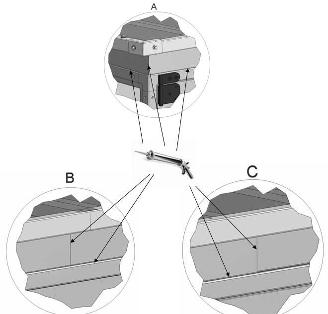
78 6 8
79 Annex 7. Speed control for rotor 7.1 Speed control The cabinet with the speed control system for the rotor is installed behind the inspection door in the rotor section. The cabinet contains the speed controller with all components, terminal blocks, LED displaying the operation mode, the dual position DIP switch with 8 sliding levers for programming the rotor motor signal and a button for the activation of the test mode. Through the different combinations of the 8 sliding levers of this dual position DIP switch, the correct signal is available for the different motors used for the air handling units. The sliding levers are set and the function is checked at the factory. The positions of the levers appear from the tables below Selection of correct signal via the 8 DIP switch levers The 8 DIP switch levers Position Function Up Active = ON 1 Down Deactivated = OFF 0 Code The factory sets the positions of the 8 DIP switch levers for the maximum of 12 revolutions per minute for standard temperature exchangers and for hygroscopic exchangers. The position of each DIP switch lever is shown below. Rotor 12 rpm DV Condensation/temperature (ST), Sorption Hybrid (SH) Position of DIP switches Diameter of pulley for rotors from Hoval Motor type 90TYD S214 M 7 1
80 The factory sets the positions of the 8 DIP switch levers for the maximum of 20 revolutions per minute for sorption exchangers. The position of each DIP switch lever is shown below. Rotor 20 rpm DV Sorption (HM) rotors from Hoval Position of DIP switches Diameter of pulley for rotors from Hoval Motor type 90TYD S214 M 120TYD S214 M Indication of operation mode via red and green LED as well as test of motor The LED is in the cover of the cabinet. LED indication No indication Green Green flashes Constant green and a short red flash Red flashes in series Red Value Power off Ordinary operation Ready for operation Rotor guard is activated for the short red flash by one bolt on the rotor. By counting the number of red flashes during one minute, you hereby check the number of revolutions per minute. See explanation below Alarm due to internal error. Is still operating for some minutes Number of red flashes in series Value 1 Over current 2 Over voltage 3 Under voltage 4 Failure in the controller 7 2
81 Restart of rotor: Switch off power and switch on power again or Press the test button inside the cabinet Test of motor by checking the resistance in all 3 windings Motor sizes 90TYD S214 M 120TYD S214 M Ohm 40Ω 18Ω Setting of constant speed: Set DIP switch 4 in position ON, and the revolutions are controlled by the adjustable potentiometer on the board. Test: Set DIP switch 4 in position ON Press the test button, and the revolutions are controlled by the adjustable potentiometer on the board. 7 3
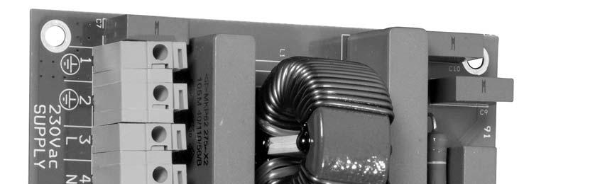
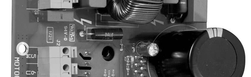
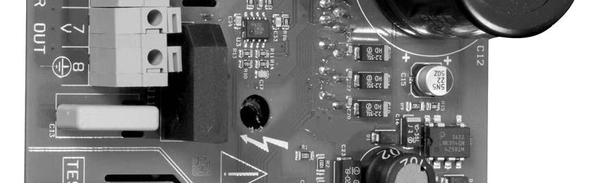
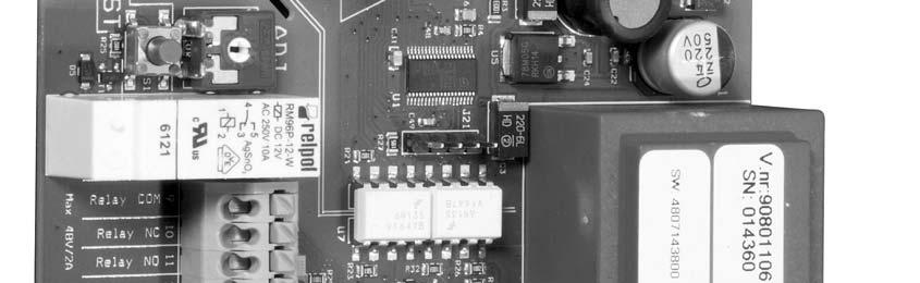
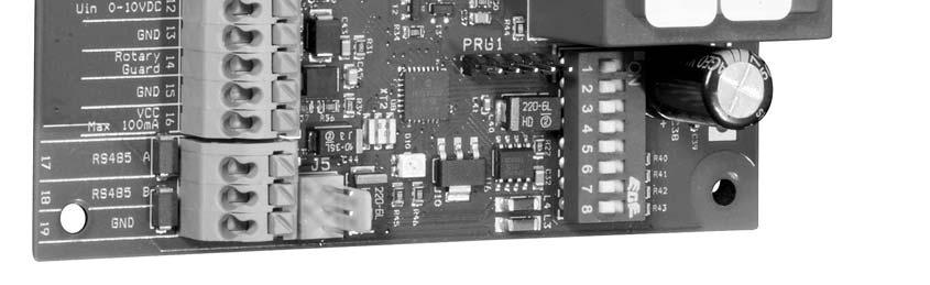
82 7.1.3 Information about connection of cables to terminals on the control board. 7 4
83 Connection of cables to the terminals on the board Terminal Connection 1 Earth supply 2 Earth supply 3 Fase supply 4 Neutral supply 5 Rotor turns upwards seen from inspection side. 6 Terminal 5 = wire 1 Terminal 6 = wire 2 7 Terminal 7 = wire 3 Rotor turn downwards seen from inspection side. Terminal 5 = wire 2 Terminal 6 = wire 1 Terminal 7 = wire 3 8 Earth for rotor motor Test Set DIP switch 4 in position ON and press the button for test. The signal is controlled by the potentiometer at constant speed and not by any signal from the control system. Adjust Is activated by setting DIP switch 4 at OFF and DIP switch 5 at ON. Hereby the maximum revolutions can be adjusted between 50 and 100 % by the potentiometer. Usually the factory setting is OK, but with this potentiometer the maximum revolutions can be reduced or increased. 9 Alarm signal COM (common) 10 Alarm signal Relay is normally closed (this is used by the control system from Systemair) 11 Alarm signal Relay is normally open (this is not used by the control system from Systemair) 12 Control signal input is 0 10 volt DC 13 Control signal input ground 14 Rotor guard (black cable from rotor guard from Systemair) 15 Rotor guard (blue cable from rotor guard from Systemair) 16 Rotor guard (brown cable from rotor guard from Systemair) 17 For BUS signal RS485 A (green wire from Systemair control system) 18 For BUS signal RS485 B (yellow wire from Systemair control system) 19 For BUS signal ground (white wire from Systemair control system) 7 5


84 7.2 Installation of motor that turns rotor and sensor for rotation Fig.1 Fig. 1 The motor is installed by delivery Fig.2 Fig.3 Fig.4 Fig. 2, 3 and 4 The motor is mounted on a console. Between motor and console is mounted 4 shock absorbers with M8 bolts. Fig.5 Fig. 1 and 5 The motor must be placed so that the belt positions itself in the middle of the rotor 7 6

85 Fig.6 1 4mm Fig. 6 The sensor for control of rotation, must be placed 1 4 mm from the rotor. 7 7
86 Annex 8. Reversible heat pump for cooling and heating 8.1 DVU HP section (reversible heat pump unit) The air handling unit section DVU HP is a separate section in the air handling unit, containing a complete stand alone reversible heat pump system (heating and cooling). If the air handling unit was delivered with this section, a separate manual about the heat pump was enclosed in the separate cover. 8 1
87 Annex 9. Menu for internal controller in the DVU HP If the air handling unit was delivered with this section, a separate manual about the heat pump was enclosed in the separate cover. 9 1
88 Annex 10. ECblue fan motor 10.1 Connection 4 Input V 5 PWM input, f = khz For ECblue 3 ~ types and when connecting 1 ~ types between two outer conductors, only all-current sensitive fault current circuit breakers (type B) are allowed ( EN , Art. 5.2). 10 1
. 11, 14 Relay output K1 for fault indication.")
, the relay remains energized.")
89 Residual current operated protective devices Terminal Function / connection L1, N, PE Mains connection for 1 ~ types (observe the line voltage indicated rating plate). L1, L2, L3, PE Mains connection for 3 ~ types (observe the line voltage indicated rating plate). 11, 14 Relay output K1 for fault indication. * For operation the relay is energized, connections 11 and 14 are bridged. For fault the relay is de-energized ( Diagnostics / faults). When switching off via enable (D1 = Digital In 1), the relay remains energized. E1, GND Analog input for setting speed via 0-10 V or PWM signal * 10V 24V Voltage supply for speed setting by 10 kω potentiometer. Voltage supply for external devices. D1, +24V Digital input for enable. * Device ON for closed contact. Controller OFF with opened contact. *Function for standard factory setting, different presetting possible. UL: Input (Line) Cu connection leads with the following specifications must be employed: Minimum insulation temperature of 80 C Terminal tightening torque for field block (L1, N, and/or L1, L2, L3) of 5-7 Lb In. (Exception: spring-cage terminal for motor size line voltage 3 ~ V) Terminal tightening torque of 4.5 Lb In for field block (K1). Terminal tightening torque of 4.5 Lb In for all other field blocks. Terminal tightening torque of 2.2 Lb In for add-on modules Diagnostic/faults Status Out with flash code 10 2
Geniox Comfort with control system Air handling unit. User Manual
 Geniox Comfort with control system Air handling unit User Manual GB Document in original language Part number of this manual 90925xxx Detailed table of contents on the following pages General description
User manual for reversible heat pump
 User manual for reversible heat pump Heat pump system integrated in Geniox, DV or TIME air handling unit Manual version 1.01.14 Part number of this manual 90925374 Contents DECLARATION OF CONFORMITY EXAMPLE...2
Air Handling Units. Quick Guide to Danvent DV
 Fans Air Handling Units Air Distribution Products Air Conditioning Fire Safety Air Curtains and Heating Products Tunnel Fans Air Handling Units Quick Guide to Danvent DV Den Blå Planet, National Aquarium
Air Handling Units. Danvent DV 190 and
 Air Handling Units Danvent DV 190 and 240 www.systemair.dk arge Very large DV 190 and 240 Systemair has developed an extensive expertise within major Air Handling Units up till now usually built as individual
Danvent DV 190 and 240
 Fans Air Handling Units Air Distribution Products Air Conditioning Fire Safety Air Curtains and Heating Products Tunnel Fans Danvent DV 190 and 240 Air Handling Units with High Capacity Danvent DV 190
Installer manual GreenMaster-HP
 Installer manual GreenMaster-HP Transport and installation Ventilation unit IHB EN 1747-2 8017172 2 GreenMaster-HP Transport and installation Introduction Here you can read about how best to handle the
Indholdsfortegnelse. Danvent Air Handling Units SERVICE MANUAL
 Indholdsfortegnelse Danvent Air Handling Units SERVICE MANUAL Service Servicing of the Air Handling Unit Your ventilation system is equipped with a Danvent Air Handling Unit (AHU) which will contribute
Air Handling Units. Geniox. Quick guide
 Air Handling Units Geniox Quick guide Copyright: Systemair A/S, 2. edition 2018. We accept no liability for printing errors or alterations of products. The dimensions and data used in this leaflet are
Topvex SR03, SR04, SR06 Compact Air Handling Unit
 Compact Air Handling Unit GB GB Corrigo ver. no. 1.2-1-00 Manufacturer Our products are manufactured in compliance with applicable international standards and regulations. Systemair AB Industrivägen 3
Danvent DV. Modular Air Handling Unit
 Fans Air Handling Units Air Distribution Products Air Conditioning Fire Safety Air Curtains and Heating Products Tunnel Fans Danvent DV Modular Air Handling Unit Bella Sky Hotel Copyright: Systemair A/S
Fans Air Handling Units Air Distribution Products Fire Safety Air Conditioning Air Curtains and Heating Products Tunnel Fans. Geniox.
 Fans Air Handling Units Air Distribution Products Fire Safety Air Conditioning Air Curtains and Heating Products Tunnel Fans Geniox Quick guide Copyright: Systemair A/S, 1. edition 2017. We accept no liability
VEX250H with rotary heat exchanger and EXact control system
 3003433-2014-04-11 VEX250_EXact VEX250H with rotary heat exchanger and EXact control system Unit supplied with (factory fitted): Compact filter FP Filter bag FB Trim damper and blowout zone,tb250 The following
TopMaster Air Handling unit. Installation instructions
 Installation instructions Safety Instructions Operation of Air Handling units and accessories WARNING Installation may only be carried out by qualified personnel. Before taking the air handling unit into
Topvex SR 09, 11, Topvex TR Compact Air Handling Units
 Topvex SR 09, 11, Topvex TR 09-15 Compact Air Handling Units Installation instructions Document in original language 125593 A003 GB Copyright Systemair AB All rights reserved E&OE Systemair AB reserves
Installation and maintenance instructions for cabin units type vertical IDAC (V50)
") GB Installation and maintenance instructions for cabin units type vertical IDAC (V50). Application. Bundled parts. Handling. Marking. Weight. Transport. Storage 5. Installation 5. Mounting 5. Water trap
GB Installation and maintenance instructions for cabin units type vertical IDAC (V50). Application. Bundled parts. Handling. Marking. Weight. Transport. Storage 5. Installation 5. Mounting 5. Water trap
INSTALLATION, COMMISSIONING AND OPERATING MANUAL
 INSTALLATION, COMMISSIONING AND OPERATING MANUAL 1 YTBV-D-CE42_0109 CONTENT Available models and capacities Supplier information Warranty Safety Emergency stops/ shutdowns About this manual Models Physical
SPECIFICATION GUIDE FLEXAIR. Possibility to add auxiliary heaters: Gas, Electrical Heater, Hot Water Coil Possibility to add Heat Recovery Module
 SPECIFICATION GUIDE FLEXAIR Air-cooled packaged Rooftop unit Cooling only or Heat Pump Nominal cooling capacity: 85 to 234 kw Nominal heating capacity: 83 to 226 kw Possibility to add auxiliary heaters:
VEX280H with rotary heat exchanger and EXact control system
 3003206-2014-04-15 VEX280_EXact VEX280H with rotary heat exchanger and EXact control system Unit supplied with (factory fitted): VEX280-1 VEX280-2 FP compact filter FB filter bag TB280 trim damper and
KITCHEN EXHAUST FAN GLEC-6 INSTALLATION AND MAINTENANCE
 KITCHEN EXHAUST FAN GLEC-6 INSTALLATION AND MAINTENANCE 2 GLEC-6 - Installation and maintenance CONTENTS 1 Important information... 3 2 Safety notes... 3 3 Technical description...4 4 Transport... 6 5
Topvex SF02-SF12 Air Handling Unit
 Topvex SF02-SF12 Air Handling Unit Installation instructions Document in original language 130324 A004 GB Copyright Systemair AB All rights reserved E&OE Systemair AB reserves the rights to alter their
Assessment Schedule - TS8
 The Assessor shall determine the business s commitment and support to good and safe working practices; also that it has a positive culture in all aspects of its work. In particular, the assessor shall
Xcell 270 Longlife DC wholehouse heat recovery unit
 Xcell 270 Longlife DC wholehouse heat recovery unit Installation and maintenance instructions Xpelair Xcell 270 Longlife DC wholehouse heat recovery unit Xcell 270, Xcell 270BP Please leave this leaflet
DVU-HP. Integrated Reversible Heat Pump System
 Fans Air Handling Units Air Distribution Products Air Conditioning Fire Safety Air Curtains and Heating Products Tunnel Fans Integrated Reversible Heat Pump System 2 Integrated Reversible Heat Pump System
AHU INSTALLATION & OPERATION MANUAL
 AHU INSTALLATION & OPERATION MANUAL VERSION 2 AIR HANDLING UNIT MODELS: AHU 500, AHU 900, AHU 1200, AHU 1700, AHU 2000, AHU 2500, AHU3500, AHU 4500, AHU 5000, AHU 6000, AHU 7000, AHU 8000, AHU 10000, AHU
User and maintenance manual
 GB User and maintenance manual IMPORTANT SAFETY INSTRUCTIONS These instructions shall also be available on website: docs.whirlpool.eu. YOUR SAFETY AND THAT OF OTHERS IS HIGHLY IMPORTANT. This manual and
Installation and Maintenance
 1.0 INTRODUCTION MRXBOXAB-ECO-LP1 (Standard Unit) MRXBOXAB-ECO-LP1-OH (Opposite Hand Unit) Mechanical Ventilation Unit with Heat Recovery for Ceiling Void Mounting Installation and Maintenance The LP1
DC Heat Recovery Unit MVHR Wholehouse heat recovery unit
 DC Heat Recovery Unit MVHR Wholehouse heat recovery unit Stock Ref. N DC Heat Recovery Unit MVHR 443423 Installation, Maintenance & Users Instructions PLEASE READ INSTRUCTIONS IN CONJUNCTION WITH ILLUSTRATIONS.
TECHNICAL INFORMATION Touchtronic Clothes Dryers
 TECHNICAL INFORMATION Touchtronic Clothes Dryers Includes: T1302, T1303, T1322, T1329ci T1403 & T1405 2004 Miele This page intentionally left blank. Table of Contents GENERAL INFORMATION A. Warning and
GLEB Kitchen exhaust fan
 GLEB Kitchen exhaust fan Installation and Maintenance??.1.2013 Contents 1. Important information 2. Safety notes 3. Technical description 4. Transport 5. Mounting instructions 6. Commissioning 7. Maintenance
CMA CONDENSING UNITS FOR OUTDOOR INSTALLATION INSTALLATION AND OPERATION MANUAL
 CMA CONDENSING UNITS FOR OUTDOOR INSTALLATION ECO-FRIENDLY REFRIGERANT GAS INSTALLATION AND OPERATION MANUAL Dear Customer, Thank you for having purchased a FERROLI product. It is the result of many years
Installation and Maintenance
 1.0 INTRODUCTION MRXBOXAB-ECO-LP1SW (Standard Unit) MRXBOXAB-ECO-LP1-OHSW (Opposite Hand Unit) Mechanical Ventilation Unit with Heat Recovery for Ceiling Void Mounting Installation and Maintenance The
XB-EFA-8L-BK & XB-EFA-8R-BK
 Supply & Extract Ventilation Unit with Heat Recovery The EMC Directive 2014/30/EU The Low Voltage Directive 2014/35/EU The information contained in this document provides details of installation, operation
AIR HANDLING UNITS MANDÍK
 AIR HANDLING UNITS MANDÍK 2 CONTENTS MANDÍK, a. s. The Company... 3 Photo Gallery... 4 Unit Description... 6 Air handling unit parameters according to Eurovent... 7 Product Range of the Air Handling Units...
English CNA-CNB. Centrifugal fans Installation and maintenance
 916505-0 English CNA-CNB Centrifugal fans Installation and maintenance 916505-0 GB Centrifugal fans types CNA, CNB, CNA-M and CNB-M installation and maintenance 1. Application 2. Handling 2.1 Marking 2.2
V 120 SG - V 160 SG. Instructions for use
 V 120 SG - V 160 SG Instructions for use Warning As the appliance contains a flammable refrigerant, it is essential to ensure that the refrigerant pipes are not damaged. The quantity and type of the refrigerant
Instructions for the fan motor control system, SILVER C
 Instructions for the fan motor control system, SILVER C 1. General The motor control system is used for controlling the type EC, 0.41-10 kw fan motors in the SILVER C units. The motor control system is
PRODUCT DATA COMFORT 5000 BY NILAN. Ventilation & passive heat recovery. Passive heat recovery. < 5300 m 3 /h
 PRODUCT DATA COMFORT 5000 BY NILAN Ventilation & passive heat recovery Commercial Passive heat recovery Ventilation < 5300 m 3 /h COMFORT 5000 The Comfort 5000 is a ventilation unit suitable for central
TTV 4500 / TTV 4500 HP / TTV 7000
 TTV 4500 / TTV 4500 HP / TTV 7000 EN OPERATING MANUAL AXIAL FAN TRT-BA-TTV4500-4500HP-7000-TC-003-EN Table of contents The current version of the operating manual can be found at: Notes regarding the operating
Instructions for the fan motor control system with integrated wiring terminals SILVER C
 Instructions for the fan motor control system with integrated wiring terminals SILVER C 1. General The motor control system is used for controlling the type EC, 0.41-10 kw fan motors in the SILVER C units.
DOMEKT ReGO 400VE(W)-B Series Air Handling Units Installation and Maintenance Service Manual
-B Series Air Handling Units Installation and Maintenance Service Manual") DOMEKT ReGO 400VE(W)-B Series Air Handling Units EN Content Safety Requirements...3 Transportation...3 Brief Description of the Unit...5 Installation...6 Maintenance...11 Technical Information......13
DOMEKT ReGO 400VE(W)-B Series Air Handling Units EN Content Safety Requirements...3 Transportation...3 Brief Description of the Unit...5 Installation...6 Maintenance...11 Technical Information......13
SILENT 12 PORTABLE AIR CONDITIONER USER MANUAL
 SILENT 12 PORTABLE AIR CONDITIONER USER MANUAL Thank you for choosing ElectriQ Please read this user manual before using this innovative Air Conditioner and keep it safe for future reference. Visit our
VERSO DOMEKT. Residential ventilation units m³/h. Non residential ventilation units m³/h
 VENTILATION equipment VENTILATION equipment content DOMEKT Residential ventilation units 50 1 000 m³/h 15 VERSO Non residential ventilation units 1000 34 000 m³/h 61 Domekt R 17 Domekt R 200 V 19 Domekt
AIR COOLED CHILLERS WITH SCROLL COMPRESSORS AND CENTRIFUGAL FANS
 RAE 1402 C O K AIR R-407C Series RAE... C K Cooling capacity from 81 to 250 kw - 2 circuits The air cooled chillers of RAE C K series, with centrifugal fans, are designed for indoor installation and are
GENERAL INSTRUCTION SAFETY DIRECTIVES INSTALLATION INSTRUCTION SAFETY DIRECTIVES GENERAL INSTRUCTION
 GENERAL INSTRUCTION SAFETY DIRECTIVES INSTALLATION INSTRUCTION SAFETY DIRECTIVES Using the air handling unit... Free space for service and repair work... GENERAL INSTRUCTION Checking prior to commissioning...3
CZT CZT. High efficiency air to water heat pumps with E.V.I. compressors E.V.I. HP OTHER VERSIONS ACCESSORIES
 High efficiency air to water heat pumps with E.V.I. compressors infolinia: +48 691 262 691-15 C +63 C +43 C E.V.I. HP The series of high efficiency heat pumps has been specifically designed for use with
USER MANUAL SILENT16 PORTABLE AIR CONDITIONER
 USER MANUAL SILENT16 PORTABLE AIR CONDITIONER Thank you for choosing electriq Please read this user manual before using this innovative Air Conditioner and keep it safe for future reference. Visit our
SLS 1202 to With or without total heat recovery. u Air Cooled Screw Chillers. 262 to 916 kw. Engineering Data Manual
 u Air Cooled Screw Chillers SLS 1202 to 4004 With or without total heat recovery 262 to 916 kw Engineering Data Manual EDM SLS407-A.4GB Date : December 2008 Supersedes : TM SLS407-A.3GB/11.06 Specifications
Installation and Maintenance
 MRXBOX95B-LP1 (Standard Unit) MRXBOX95B-LP1-OH (Opposite Hand Unit) Mechanical Ventilation Unit with Heat Recovery & Summer Bypass for Ceiling Void Mounting Installation and Maintenance The EMC Directive
GB User and maintenance manual
 GB User and maintenance manual IMPORTANT SAFETY INSTRUCTIONS These instructions shall also be available on website: docs.whirlpool.eu. YOUR SAFETY AND THAT OF OTHERS IS VERY IMPORTANT This manual and
MODEL: DV72 R & L. Mechanical Ventilation with Heat Recovery Installation Instructions and User Manual
 90000556/90000557 Issue 10 9/17 MODEL: DV72 R & L Mechanical Ventilation with Heat Recovery Installation Instructions and User Manual Commissioning Data: to be completed by the installer Date of installation:
eco PREMIUM ENERGY RECOVERY UNIT» Technical instruction
 Air Comfort Air Treatment Energy Recovery eco PREMIUM ENERGY RECOVERY UNIT» Technical instruction eco PREMIUM - Technical Instruction REDA 2 Contents Description Applications... 3 Quality & environment...
lindab we simplify construction Lindab Modular air handling units Transport and assembly manual
 lindab we simplify construction Lindab Modular air handling units Transport and assembly manual Transport and assembly manual 1 General... 3 2 Warnings & Tips... 3 3 Transportation... 3 3.1 Truck loading
SOUND-INSULATED FAN. Iso-K OPERATION MANUAL. Iso-K_v.1(2)-EN.indd :20:59
-EN.indd :20:59") SOUND-INSULATED FAN OPERATION MANUAL _v.1(2)-en.indd 1 10.08.2015 15:20:59 CONTENT Introduction 3 General 3 Safety rules 3 Transport and storage requirements 3 Manufacturer's warranty 3 Fan design 4 Delivery
SOUND-INSULATED FAN OPERATION MANUAL _v.1(2)-en.indd 1 10.08.2015 15:20:59 CONTENT Introduction 3 General 3 Safety rules 3 Transport and storage requirements 3 Manufacturer's warranty 3 Fan design 4 Delivery
CPVS PRODUCT DESCRIPTION
 CPVS 20 30 PRODUCT DESCRIPTION The CHICAGO PNEUMATIC CPVS 20-30 compressor is a quiet, complete and ready-for-use unit for the production of compressed air for light and medium industrial applications.
Brown University Revised August 3, 2012 Facilities Design & Construction Standards SECTION AIR HANDLING UNITS
 SECTION 23 70 00 AIR HANDLING UNITS PART 1. GENERAL 1.1 Section includes air-handling units to 15,000 cfm and accessories. 1.2 Related Sections 1 : A. Division 01 - Brown University Standard for Narragansett
INSTALLATION AND USER MANUAL
 INSTALLATION AND USER MANUAL t Thank you for choosing Aqua inverter heat pump. This manual provides you necessary information for optimal use and maintenance, please read it carefully and keep it for subsequent
INSTALLATION, OPERATION AND MAINTENANCE MANUAL
 INSTALLATION, OPERATION AND MAINTENANCE MANUAL Air Curtains RUND Please, read these instructions carefully before attempting installation SECURITY ADVISE SYMBOLS Attention, Danger, Safety Advice! Danger
Supply air unit VEKA Installation & Maintenance
 November 2008 Safety instructions Operating the air treatment unit and accessory components WARNING Before the air treatment unit is taken into service, any free connections must be provided with protective
HEAT RECOVERY AIR HANDLING UNIT
 HEAT RECOVERY AIR HANDLING UNIT OPERATION MANUAL KOMFORT_L v2(2)_en.indd 1 07.08.2015 15:0:44 CONTENTS Introduction General Safety regulations Transportation and storage regulations Manufacturer's warranty
INSTALLATION, OPERATION & MAINTENANCE MANUAL
 CENTRAL FANS COLASIT LTD Unit 12A, Palmers Road, East Moons Moat, Redditch. Worcs. B98 0RF Tel: 01527-517200 Fax: 01527-517195 Edition 04_13 INSTALLATION, OPERATION & MAINTENANCE MANUAL CIV Fan Range Valid
Application guide FLATAIR - FLCK/FLHK. Providing indoor climate comfort
 Application guide FLATAIR - FLCK/FLHK Providing indoor climate comfort MSL60E-0701 12-2006 Congratulations you have made a wise choice and we feel sure that it will meet your expectation INDEX CONTENTS
INSTALLATION OPERATION & MAINTENANCE INSTRUCTION HEAT RECOVERY UNITS VHR MODELS
 INSTALLATION OPERATION & MAINTENANCE INSTRUCTION HEAT RECOVERY UNITS VHR MODELS TSEK VENCO Havalandırma ve Makina San.ve Tic. A.Ş. 2004. Cad. No:5 45400 OSB Turgutlu MANISA / TURKİYE Tel: +90 (236) 332
Portable Air Conditioner USER MANUAL
 AC12 AC12HP Portable Air Conditioner USER MANUAL Thank you for choosing this innovative Amcor air conditioner. We suggest that you keep this manual in a safe place for future reference. It describes the
39 HQ Air Handling Units AiroVision
 VDI 6022 39 HQ Air Handling Units AiroVision Assembly/Installation, Commissioning, Maintenance Manual Type tested Production monitored AHU N : 08.02.251 Range: 39HQ DIN 1946-4 EN 13053 2 Code No: B.8.1.3i
AIR COOLED CHILLERS FOR OUTDOOR INSTALLATION WITH INTEGRATED FREE COOLING MULTISCROLL SERIES
 AIR COOLED CHILLERS FOR OUTDOOR INSTALLATION WITH INTEGRATED FREE COOLING MULTISCROLL SERIES COOLING CAPACITY FROM 76 TO 612 Kw 1 AND 2 COOLING CIRCUITS RAE 1702 F Kc + P2 28 Above picture is only indicative
Installation and Maintenance Novax Smoke Exhaust Fan Type ACN Smoke
 918149-0 GB Installation and Maintenance Novax Smoke Exhaust Fan Type ACN Smoke 1. Application 2. Handling 2.1 Marking 2.2 Weight 2.3 Transport 3. Storage 4. Installation 4.1 Prior to attachment 4.2 Attachment
ISCG90SS _03 ISCG90SS
 ISCG90SS 60900355_03 ISCG90SS GB IE [01] x 1 [02] x 1 [03] x 1 [04] x 8 [05] x 1 [06] x 4 [07] x 1 [08] x 1 [09] x 1 [10] x 4 [11] x 4 [12] x 1 [13] x 4 (6x70mm) [14] x 8 (6.3x17x2mm) 1 : 1 [15] x 4 (3.9x18mm)
F17W44_MFB_F_EN INSTALLATION INSTRUCTIONS
 F17W44_MFB_F_EN INSTALLATION INSTRUCTIONS Contents Page User instructions 3-5 General 3 Fan installation 3-4 Maintenance 3 Electrical installation 5 Troubleshooting 5 Technical description 6-8 General
CMA TECHNICAL MANUAL CONDENSING UNITS FOR OUTDOOR INSTALLATION O L S A F RA N
 E S A RE F R E IG RA N T G TECHNICAL MANUAL -FRIEND Y CONDENSING UNITS FOR OUTDOOR INSTALLATION O L CMA C 2 The manufacturer declines all the responsabilities regarding inaccuracies contained in this manual,
Instructions for the BASIC Air Handling System, Sizes General 1.1 Description of the System
 Instructions for the BASIC Air Handling System, Sizes 004 055 1. General 1.1 Description of the System The BASIC System is a complete modular air handling unit. The unit consists of blocks, i.e. a number
PRODUCT DATA COMPACT P - SERIES BY NILAN. Sanitary hot water production. Heating. Ventilation < 300 m 3 /h. Passive heat recovery.
 PRODUCT DATA COMPACT P - SERIES BY NILAN Domestic Passive heat recovery Active heat recovery Ventilation < 300 m 3 /h Comfort heating Comfort cooling Sanitary hot water production Heating THE VENTILATION
INSTALLATION, OPERATION AND MAINTENANCE MANUAL. Air curtain SMART
 INSTALLATION, OPERATION AND MAINTENANCE MANUAL Air curtain SMART Read instructions carefully before attempting installation. Deliver this manual to end user. SECURITY ADVISE SYMBOLS Attention, Danger,
EAGLE 2000B EAGLE 2000BE EAGLE 2000EBT MUST READ MANUAL PRIOR TO INSTALLING MACHINE
 EAGLE 2000B EAGLE 2000BE EAGLE 2000EBT MUST READ MANUAL PRIOR TO INSTALLING MACHINE Contents 1 Machine Safety Information 3 1.5 Safety Precautions Prior to Operating Machine 6 2 Machine Installation 7
AIR HANDLING UNITS RIS P EKO 3.0. New range - 5 sizes, 20 models! Efficient EC. E f f i c i e n c y up to 94%! E x t r e m e l y low height! fans!
 AIR HANDLING UNITS RIS P EKO 3.0 1 2 3 4 fans! Efficient EC E f f i c i e n c y up to 94%! E x t r e m e l y low height! New range - 5 sizes, 20 models! Contents Basic features 4 RIS P EKO 3.0 full range
FWC153, FWC304, FWC604 & FWC624
 FWC153, FWC304, FWC604 & FWC624 Wine Coolers Installation, use and maintenance www.cda.eu Important The CDA Group Ltd cannot be held responsible for injuries or losses caused by incorrect use or installation
AIR COOLED CHILLERS WITH SCROLL COMPRESSORS AND CENTRIFUGAL FANS
 RAE 201 C K RAE 482 C K AIR R-407C Series RAE... C K from 19 to 83 kw - 1 and 2 circuits The air cooled chillers of RAE... C K series, with centrifugal fans, are designed for indoor installation and are
TTK 75 ECO OPERATING MANUAL DEHUMIDIFIER TRT-BA-TTK75ECO-TC-002-EN
 TTK 75 ECO EN OPERATING MANUAL DEHUMIDIFIER TRT-BA-TTK75ECO-TC-002-EN Table of contents Notes regarding the operating manual... 01 Information about the device... 02 Safety... 04 Transport...05 Start-up...05
FWC152, FWC303, FWC603 & FWC623 Wine Coolers Installation, Use and Maintenance
 FWC152, FWC303, FWC603 & FWC623 Wine Coolers Installation, Use and Maintenance Customer Care Department The Group Ltd. Harby Road Langar Nottinghamshire NG13 9HY T : 01949 862 012 F : 01949 862 003 E :
SECTION SEQUENCE OF OPERATIONS FOR HVAC CONTROLS
 PART 1 - GENERAL SECTION 23 09 93 SEQUENCE OF OPERATIONS FOR HVAC CONTROLS 1.1 SUMMARY A. This Section includes control sequences for HVAC systems, subsystems, and other equipment. B. See Division 23 Section
HEAT RECOVERY VENTILATOR
 HEAT RECOVERY VENTILATOR HRV H 00 ERV H 00 HRV H 300 ERV H 300 EN OPERATION MANUAL HRV /ERV H 00(300) www.blaubergventilatoren.de CONTENTS Application... Delivery set...3 Unit designation key...3 Basic
ACN SMOKE INSTALLATION AND MAINTENANCE
 NovAx ACN SMOKE INSTALLATION AND MAINTENANCE 918149-0 English 918149-0 GB Installation and maintenance NovAx smoke exhaust fan type ACN smoke 1. Application 2. Handling 2.1 Marking 2.2 Weight 2.3 Transport
INSTALLATION AND USER MANUAL
 INSTALLATION AND USER MANUAL Thank you for choosing inverter heat pump. This manual provides you necessary information for optimal use and maintenance, please read it carefully and keep it for subsequent
CENTRIFLOW 3D. >> Installation and Maintenance. air comfort. CentriFlow 3D
 CENTRIFLOW 3D Plug fan GMEC >> Installation and Maintenance air comfort CentriFlow 3D 2 Plug Fan CentriFlow 3D GMEC Installation and Maintenance Important Information, Safety notes, Technical Description
PLENUM FAN EQLK PLENUM FAN, DIRECT-DRIVEN
 EQLK, DIRECT-DRIVEN INSTALLATION AND MAINTENANCE INSTRUCTIONS Contents Page Installation options...... 2 Checks to be made prior to commissioning...2 Electrical connections.....2 Measures before starting.....
INSTALLATION, OPERATION AND MAINTENANCE MANUAL
 INSTALLATION, OPERATION AND MAINTENANCE MANUAL Air Curtains OPTIMA Please, read these instructions carefully before attempting installation SECURITY ADVISE SYMBOLS Attention, Danger, Safety Advice! Danger
GLEB. >> Installation and Maintenance. Air Comfort. Air movement. Duct & Box Fans
 Air Comfort Air movement Duct & Box Fans GLEB KITCHEN exhaust FAN >> Installation and Maintenance Kitchen Exhaust Fan GLEB Installation and Maintenance Important Information, Safety notes, Technical Description
Novenco Air Handling Units
 Novenco Air Handling Units Climaster ZCF Guide 919432-0 GB Important This document is provided As is and is subject to change without notice. Novenco reserves this right due to continuous product development.
BHW INSTALLATION, OPERATION AND MAINTENANCE MANUAL MEDIUM STATIC PRESSURE DUCTABLE TYPE. Models:
 INSTALLATION, OPERATION AND MAINTENANCE MANUAL BHW MEDIUM STATIC PRESSURE DUCTABLE TYPE Models: 174 205 358 410 515 720 724 Cooling capacities from 3,1 to 25 KW Heating capacities from 4,5 to 55,5 KW Thank
USER S MANUAL. VCU/VCUN Series CENTRIFUGAL FAN IN SCROLL CASING
 USER S MANUAL VCU/ Series CENTRIFUGAL FAN IN SCROLL CASING 2 CONTENTS Introduction Use Delivery set Designation key Technical data Safety requirements Design and operating logic Mounting and set-up Connection
Fans Air Handling Units Air Distribution Products Fire Safety Air Curtains and Heating Products Tunnel Fans. Topvex SoftCooler TR. Specification data
 Fans Air Handling Units Air Distribution Products Fire Safety Air Curtains and Heating Products Tunnel Fans Topvex SoftCooler TR Specification data 2 Topvex SoftCooler TR Comfort cooling, ready from factory
TopMaster Air Handling unit. Technical data
 Technical data Contents Page Description of the unit... 3 Design... 4 Technical data Size 030... 5 Size 0... 6 Accessories... 7 Controls... 9 Control functions... 10 Order codes... 11 Fläkt Woods 8180
Installation Operation Maintenance. Ductable water unit FWD FWD-SVX01D-E4
 Installation Operation Maintenance Ductable water unit FWD 08-12 - 20-30 - 45 General Information Foreword These installation, operation and maintenance instructions are given as a guide to good practice
UNITES TERMINALES ET MINI CTA FIDJI
 1 UNITES TERMINALES ET MINI CTA FIDJI 2 Air Handling Unit Fidji Presentation High Effi ciency superposed Heat Recovery Unit, with control factory mounted, for indoor or outdoor installation. Solution adapted
B. Unit construction shall comply with ASHRAE 15 Safety Code, NEC, and ASME applicable codes (U.S.A. codes).
.") Guide Specifications PART 1 GENERAL 1.01 SYSTEM DESCRIPTION Microprocessor controlled, air-cooled liquid chiller utilizing scroll compressors, low sound fans, hydronic pump system and optional fluid storage
Guide Specifications PART 1 GENERAL 1.01 SYSTEM DESCRIPTION Microprocessor controlled, air-cooled liquid chiller utilizing scroll compressors, low sound fans, hydronic pump system and optional fluid storage
VERSO Air Handling Units
 Energy efficient solutions for profitable indoor climate VERSO-S air supply units VERSO-R air handling units equipped with regeneration system VERSO-P air handling units equipped with recuperation system
VEX100 series Air handling units with cross-flow heat exchanger
 Product information - Version 6 VEX100 series Air handling units with cross-flow heat exchanger VEX140: 400-2200 m 3 /h VEX150: 700-3600 m 3 /h VEX160: 1100-5000 m 3 /h VEX170: 1400-8400 m 3 /h Contents
Jet Fan Types AUC/ARC/AUR/ARR/AUO/ARO Installation and Maintenance
 916503-0 GB Jet Fan Types AUC/ARC/AUR/ARR/AUO/ARO Installation and Maintenance 1. Main components 2. Application 3. Handling 3.1 Marking 3.2 Weight 3.3 Transport 4. Storage 1. Main components: Types ARC,
TKM 50 HE. High efficiency in air treatment
 TKM 5 HE High efficiency in air treatment The art of handling air TROX is the leader in the development, manufacture and distribution of components and systems for the ventilation and air conditioning
lindab we simplify construction Lindab Modular air handling units Connection, start-up and commissioning manual
 Lindab Modular air handling units Connection, start-up and commissioning manual Connection, start-up and commissioning manual 1 General... 3 2 Warnings and Tips... 3 3 Functional sections... 3 3.1 Fan
INLINE СENTRIFUGAL FAN BOX BOX-R OPERATION MANUAL
 INLINE СENTRIFUGAL FAN BOX BOX-R OPERATION MANUAL CONTENT 3 Introduction 3 General 3 Safety rules 3 Storage and transportation rules 3 Manufacturer s warranty 4 Fan design 4 Delivery set 5 Technical data