Instrumentation and Controls
|
|
|
- Alan Knight
- 5 years ago
- Views:
Transcription
1 Instrumentation and Controls
2 Objectives Identify the components of a pneumatic system Describe the different types of HVAC systems Discuss types of sensors Explain comfort Discuss HVAC controls
3 Comfort The condition that occurs when a person cannot sense a difference between themselves and the surrounding air
4 Comfort Five requirements are proper Temperature Humidity Filtration Circulation Ventilation Picture
5 Temperature Comfort zone is approximately 75 F Varies from person to person Regulated by the hypothalamus gland Controls blood flow to capillaries Blood vessels transfer heat to skin Increase in body temperature, increase in blood flow-flush face
6 Humidity The amount of moisture present in the air Determines how slowly or rapidly perspiration evaporates from the body Perspiration flow regulates body temperature Evaporation of perspiration cools the body
7 Humidity If temperature remains constant: Higher humidity, slows evaporation rate Person would feel warm Lower humidity, faster evaporation rate Person would feel cooler Comfort is attained, approximately 50%
8 Humidity Humidifier - device that adds moisture to the air by causing water to evaporate into the air (heating mode) Dehumidifier - device that removes moisture from the air causing moisture to condense (cooling mode) Dew point- temperature that water can no longer be suspended in air Picture
9 Contents Comfort Thermodynamics Heat measurement Heat transfer Psychometrics
10 Thermodynamics The science of thermal energy (heat) and how it transforms to and from other forms of energy First law of thermodynamics - heat as a form of energy can not be created or destroyed, but may be changed from one form to another Picture
11 Thermodynamics Second law of thermodynamics: heat always flows from a material at a high temperature to a material at a low temperature Picture
12 Heat Measurement The measurement of energy contained in a substance and is identified by: Temperature difference Change of state All substances exist in either a solid, liquid, or gas state Change of state - a substance changes from one physical state to another when heat is added or removed
13 Heat Measurement Substances may contain Sensible heat - changes temperature Picture measured with a thermometer or sensed by a person Latent heat - changes state without temperature change Ice or boiling water British thermal unit (Btu) Used in rating heating and cooling equipment Ton of cooling (12,000 Btu/hr)
14 Heat Transfer Movement of heat from one material to another Always higher to lower temperature (2 law of thermodynamics) Heat transfer rates increases with the temperature difference between two substances nd
15 Heat Transfer Three methods are: Conduction - heat is passed molecule to Video molecule through the material Video Video Convection - when currents circulate between warm and cool regions of a fluid Radiation - transfer in the form of radiant energy (electromagnetic waves)
16 Heat Transfer Comfort conditioning in a building may use any of these three methods or a combination Quantity of heat involved in heat transfer is a function of Weight Specific heat Temperature difference
17 Weight The force with which a body is pulled downward by gravity Heat Calculation Weight is used instead of volume Weight remains constant Volume of most materials changes with a change in temperature Expressed in pounds (lb) or grams (g)
18 Specific Heat Ability of a material to hold heat Normally given in Btu/lb/ F Water is 1 and is used as the standard for calculating All substances have a constant value Most materials are less than water Water holds a large quantity of heat Video
19 Psychometrics Scientific study of the properties of air and the relationships between them The properties of air determines the condition of the air - comfort Comfort (properties of air) are the characteristics of air which are: Temperature Humidity Enthalpy Volume
20 Temperature Temperature is the most important variable measured and controlled in a commercial HVAC Measurement of temperature indicates intensity, not quantity (Btu) Expressed in: Fahrenheit scale Celsius scale
21 Fahrenheit Fresh water at normal atmospheric pressure (14.7psia) 32 F is freezing 212 F is boiling
22 Temperature Temperature is most often measured using a thermometer Should be good quality and calibrated Various types of dry bulb readings Stem thermometer Bimetallic Electronic Infrared Video
23 Humidity Produced from water that has evaporated into the air Inadequate or excessive amount causes discomfort
24 Humidity The moisture content of the air can be checked by using a combination of dry-bulb and wet-bulb temperatures Dry-bulb - measures temperature of air without reference to humidity Wet-bulb - temperature of the air with humidity taken into account
25 Humidity Measured by a: Hygrometer Sling psychrometer with a psychrometric chart
26 Relative Humidity Most practical humidity measurement The amount of moisture in the air compared to the amount of moisture it could hold if it were saturated (full of water) at the same temperature Saturated air carries as much moisture as possible before moisture forms into water droplets
27 Enthalpy The total heat contained in a material The sum of latent and sensible heat Expressed in Btu/lb of moist air A better indicator than dry bulb Outside enthalpy is often used to determine the suitability of outside air for use in place of mechanical cooling
28 Volume (pressure) Pressure is the force created by a substance per unit of area Various pressures affect our comfort or helps measures our comfort Atmospheric Gauge Absolute Picture
29 Inches of Water column Used when pressure is too small to be measured in psi Measured in a unit of pressure that is still force per unit of area but in a smaller graduation Generally used to measure the pressure in a duct system Picture
30 Commercial HVAC Systems
31 Objectives Name five common types of commercial heating systems Name three common types of commercial cooling systems Identify the components that make up the air handling unit Name six types of air handling units
32 Content Types of commercial HVAC systems Components of an air handling unit Constant-Volume air handling units Variable-Volume air handling units
33 Commercial HVAC Systems Provides comfort to building occupants throughout the year in Office buildings Strip malls Stores Restaurants Other commercial facilities
34 Commercial HVAC Systems Generally contains: Heating system Ventilating system Cooling system Humidification system Dehumidification system Air filtration system
35 Heating Systems A system that increases the temperature of a building Classified by the medium or heat source used
36 Heating Systems Common heating systems Hot water Steam Electric Heat pump Natural gas/fuel oil-fired
37 Air Handling Units A device that conditions and distributes air throughout a building Consist of the following components:
38 Dampers An adjustable metal blade or set of blades used to control the flow of air Commonly used to control: Outside air Return air Exhaust air Air flow across heating/cooling coils Video
39 Constant-Volume AHUs An air handling unit that moves a constant volume of air Operate at their rated capacity (cfm) at all times Controls building temperature by: changing the temperature of the medium not the volume
40 Constant-Volume AHUs Commonly used in buildings Disadvantage is no energy savings Fan operates at rated power 100% of the time
41 Constant-Volume AHUs Types Single-zone Multizone Dual-duct Terminal reheat Induction
42 Single-Zone AHUs Provides HVAC to only one building zone or area Size of the zone is limited Temperature differences or stratification Identified by the heating and cooling coils Coils are in series Controlled directly by the zone or area Room stat Picture
43 Multizone AHUs Provides HVAC to more than one building zone or area Identified by the heating and cooling coils located side by side in different ducts Hot deck Cold deck Picture
44 Multizone AHUs Dampers Mixes hot and cold air for each zone Are controlled from thermostats or controllers in each zone Video
45 Dual-Duct AHUs Has hot and cold air ducts connected to mixing boxes at each building space Dampers located in the mixing box Mixing box is usually located above the ceiling in the building space Video Picture
46 Terminal Reheat AHUs Delivers air at a constant 55 F temperature to building space Each space has a reheat coil in the ductwork located in or near the space Steam Hot water Electric Picture
47 Terminal Reheat AHUs Thermostat or controller controls the reheat coil valve Allows valve to open to satisfy space temperature setpoint Medium will heat 55 F air to set point Generally 68 F - 72 F Reheat valve will close when thermostat or controller is satisfied Video
48 Induction AHUs Maintains a constant 55 F air temperature and delivers the air to the building space at high duct pressure High-pressure air is delivered to a slotted wallmounted unit Forced out through an induction nozzle into the space Video
49 Induction AHUs High-velocity air flow causes building space air (return air) to flow into the unit Induced air flow is directed across heating coils Coils controlled controller Picture by thermostat or
50 Induction AHUs The high-pressure air output is: Noisy Energy inefficient
51 Content Introduction Types of commercial HVAC systems Components of an air handling unit Constant-Volume air handling units Variable-Volume air handling units
52 Variable Air Volume AHUs Moves a variable volume of air Varies the amount of air to the space instead of varying the temperature Became popular during the 1970 s energy crisis Delivers a constant 55 F year-round Also known as VAVs Video
53 Variable Air Volume AHUs Purpose of system VAV terminal boxes reduces volume of air Supply fan performs less work Uses less energy The most common HVAC system installed in new commercial buildings Picture
54 Variable Air Volume AHUs Disadvantages: Noisy Possible inability to properly heat building space Stratification of air May also be unable to deliver the proper amount of outside air for ventilation IAQ issues
55 Variable Air Volume AHUs Maintains a static pressure of.5-1 water column To control the volume of air by the supply fan: Bypass dampers Pre-rotation vane Closes supply inlet of air to the centrifugal fan Electric motor drive Variable frequency drives Picture
56 VAV Terminal Boxes Controls the amount of air flow to a building space Controlled by a thermostat in the room Designed for multiple applications Fan powered Series/parallel Picture Heat coils Hot water, steam, or electric Dual and single duct Cooling only, etc.
57 Lesson 2 Quiz Electronic equipment is sometimes shipped with silica gel to prevent damage from moisture in the air. This is an example of which of the following? A. Direct expansion cooling. B. Ventilation. C. Passive dehumidification. D. Desiccant dehumidification.
58 Lesson 2 Quiz Which of the following is not associated with lowering indoor air quality? A. Pollen. B. Halitosis. C. Pesticides. D. Vehicle exhaust.
59 Lesson 2 Quiz In a standard air-cooling system, air travels through the and is cleaned by the. A. fan, humidifiers. B. cooling coil, heat recovery device. C. ducts, filters. D. heating coil, dampers.
60 Lesson 2 Quiz Square ducts are easy to install and connect to one another, but they also: A. are the most expensive. B. require the most maintenance. C. cause the most resistance to air flow. D. are poorly insulated.
61 HVAC System Energy Sources Lesson 3
62 Objectives Name five common commercial building heating system sources Name five common commercial building cooling system sources Identify other alternate sources for cooling and heating commercial buildings
63 Contents Introduction Heating system energy sources Cooling system energy sources Alternate HVAC system energy sources
64 HVAC System Energy Sources Purpose of an HVAC system is to provide comfort to the occupants of a building Providing comfort and controlling environmental conditions in a building consumes energy
65 Heating System Energy Source Factors considered when choosing a heating system energy source include: Installation cost Energy cost per unit of energy used Local climate
66 Contents Introduction Heating system energy sources Cooling system energy sources Alternate HVAC system energy sources
67 Heating System Energy Source Commercial building heating system energy sources include: Electricity Natural gas Fuel oil Solar energy Mechanical system heat transfer
68 Electricity Common energy source for heating commercial buildings Installation cost is minimized Utilizes existing distribution system Operating (consumption) cost is high Commonly contain electric resistance elements
69 Electricity Heating elements are used in: Electric baseboards Radiant heat panels Air Handling Units (AHU) Variable Air Volume (VAV) terminal boxes
70 Natural Gas Commonly used because Plentiful Relatively inexpensive Clean burning Common gas-fired heat applications Roof top units Boilers Radiant heaters
71 Natural Gas Generally cheaper in cold climate areas where large amounts are used Create steam/hot water Steam has a large amount of heat energy Approximately 1000 Btu/lb Convenient transportation throughout building of heat energy
72 Natural Gas Disadvantages Cost of installing (piping) Piping system integrity Safety cost
73 Fuel Oil Common in areas with limited access to natural gas service Northeast U.S. Common fuel-oil applications Boilers Roof top units Back-up fuel
74 Fuel Oil Advantages Easier availability Possible lower cost Purchase large quantities when prices are low and stored in tanks (backup fuel)
75 Fuel Oil Disadvantages: Proper storage and controls Oil may require heating Environmental and pollution controls Fuel oil and natural gas are interchangeable energy sources for HVAC applications Picture
76 Solar Energy Abundant Can provide substantial amounts of energy to replace more expensive or less available fuels Natural clean fuel source Free
77 Solar Energy Most solar systems heat water for heating small commercial and residential applications Application of solar power is limited by: Climate Sunlight availability Size of the installed equipment Temperature limitations Picture
78 Solar Energy Collection and storage systems Relatively expensive Can be complicated Payback varies Generally long term
79 Mechanical Heat Transfer Heat pump Transfer heat or cooling from outdoors to indoors by reversing the refrigerant cycle Used in residential and commercial applications Balance point in heating cycle is 40 F Drastic loss of efficiency when O.A. temperature drops below 40 F
80 Mechanical Heat Transfer Advantages Eliminates piping and controls for natural gas and fuel oil Relatively cheaper than resistance Disadvantages Not widely used in northern climates Average winter temperature is below 40 F Supplemental heat (heating elements) heat
81 Contents Introduction Heating system energy sources Cooling system energy sources Alternate HVAC system energy sources
82 Cooling System Energy Source Energy sources for HVAC cooling systems include Outside air Electricity Cold water Steam or hot water Mechanical system heat transfer
83 Outside Air Basic energy source to cool a building is referred to as Free Cooling Use is limited when O.A. temperature and/or humidity allows
84 Mechanical Heat Transfer Mechanical refrigeration system Heat from the building space is absorbed and transferred to the outdoor unit Major types: Heat pump cooling mode Picture Chillers Central air
85 Electricity Common energy source to power motors Supply fans Refrigerant compressors Cooling cost effectiveness depends on the cost per unit of electricity Depends on the area in the U.S. Picture Cost of Kilowatt per hour
86 Cold Water Common in commercial buildings Generally used to transfer heat away from the condition areas Produced by: Cooling towers Holding ponds Liquid chillers Picture
87 Steam and Hot Water Costs are generally lower Not dependent on electric motor Uses existing steam or hot water in the building Used to provide cooling in absorption refrigeration systems Commonly used for large commercial or industrial applications where mechanical compression systems are not as efficient
88 Steam and Hot Water An absorption system is a nonmechanical refrigeration system Uses a fluid with the ability to absorb a vapor when it is cool and release a vapor when heated
89 Contents Introduction Heating system energy sources Cooling system energy sources Alternate HVAC system energy sources
90 Alternate Energy Source The application use of alternate HVAC energy sources generally depends on: Local availability of fuel Construction codes Energy efficiency standards
91 Control Principles Lesson 4
92 Objectives Identify four control system components Name four common controlled devices Identify four common control agents and their system Name three control functions that ensure the comfort of the occupants
93 Objectives Name four control principles (characteristics) of operating an HVAC control system Identify several application types common control
94 Contents Introduction Control system components Controlled devices Controlled agents Controlled functions Control system characteristics Control types Control system requirements
95 Control System Components A control system is comprised of a sensor, controller, and a controlled device to maintain a specific controlled variable value in a building space, pipe, or duct
96 Control System Components All HVAC control systems consist of the same basic components Variations between manufacturers are: Power supplies Types of adjustments Nomenclature Wire/pipe terminations
97 Control System Components Components include: Sensors Controllers Controlled devices Control agents
98 Sensors A device that measures a controlled variable and sends a signal to a controller Temperature Pressure Humidity
99 Sensors Output signal Pneumatic control system Air pressure Electrical control system Resistance Voltage Current
100 Sensors Sensor must be Selected for the variable to be sensed Located where it can properly sense the variable
101 Controllers Device that receives a signal from the sensor Compares it to a setpoint value Sends an appropriate output signal to a controlled device
102 Controllers Setpoint is adjustable A knob Slider Laptop Desired accuracy adjustments depends on the control system, adjustments include: Picture Proportional band Gain Throttling range
103 Contents Introduction Control system components Controlled devices Controlled agents Controlled functions Control system characteristics Control types Control system requirements
104 Controlled Devices The object that regulates the flow of fluid in a system to provide the heating, air conditioning, or ventilation effect Components must be compatible with the control system
105 Controlled Devices Common controlled devices Dampers - regulates air flow Valves - regulates water or steam flow Refrigeration compressor - delivers cooling Gas valves and electric heating elementsdelivers heating
106 Controlled Agents Fluid that flows through controlled devices to produce a heating or cooling effect Most common Hot water Steam Chilled water Hot air and cold air Electricity Refrigerants
107 Controlled Agents Distributed in different ways in a building Heating systems Cooling systems Humidification systems Ventilation systems
108 Heating systems Hot water or steam in heat exchanger Mounted in the ductwork of an AHU Convection in the actual space Valves regulate the flow Electric heating elements Mounted in the ductwork Combustion of fossil fuels
109 Cooling systems Chilled water from central plant Pumped through valves and coils mounted in ductwork of an AHU Direct expansion Uses compressor and evaporator remove heat from the space Package units Rooftop Through the wall units to
110 Cooling systems Outside air Temperature and humidity must be low enough Controlled by dampers Referred to as free cooling or economizer cooling Usually no mechanical cooling is on
111 Humidification Systems Added to the air of building spaces by Low-pressure steam Hot water vapor To prevent health problems (IAQ) and/or building damage Safety controls are always used to prevent excessively high levels
112 Ventilation Systems O.A. is introduced to the space to control Indoor Air Quality (IAQ) Flush out toxins and pollutants (CO2) Utilized even if it causes extra heating or cooling
113 Control Functions Ensures the comfort of the building occupants Temperature control Humidity control Pressure control
114 Temperature Control The most important component of comfort Accomplished by controlling Building space temperature Return air temperature Air volume
115 Space Temperature Control Thermostat or room controller is connected directly to a heating or cooling controlled device Coil valve, electric heater, dampers, etc. Sensor location in space is critical Sunlight, height (air stagnation), etc Comfort will vary in large room
116 Return Air Temperature Sensor is mounted in the return air duct An more accurate reading Average of all the temperatures of the space Prevents tampering with sensor Picture
117 Air Volume Constant volume The volume of air through the HVAC system is constant, but the temperature can vary Variable air volume Reduces air volume instead of temperature Picture Constant-temperature/variable volume Variable-speed drives or variable vanes
118 Humidity Control Sensor is generally mounted in space Connected directly to the controlled device Steam valve Many safety controls are integrated Flow switch, high humidity, etc. Picture
119 Pressure Control Includes System pressure control Differential pressure control Pressure sensor is normally located in the ductwork
120 System Pressure Control Connected to a controller which opens and closes an air volume control device Maintains a specific pressure in the system
121 Differential Pressure Control Specific pressure in the system is maintained based on a difference in pressure between two points Supply and return pressure is common Room air pressure and pressure outside the room Safety controls are added
122 Contents Introduction Control system components Controlled devices Controlled agents Controlled functions Control system characteristics Control types Control system requirements
123 Control System Characteristics All HVAC control systems operate using the same set of control principles Include Setpoint Control point Offset Feedback
124 Setpoint The desired value to be maintained by the system Can be stated in different variables Temperatures Pressures Humidity Light level Dew point Enthalpy
125 Control Point The actual value the control system experiences at any given time In many instances, the setpoint may be different than the control point
126 Offset The difference between the setpoint and the control point Depends on the accuracy of the controller
127 Feedback The measurement of the results of a controller action by a sensor or switch
128 Closed Loop Control The arrangement of a controller, sensor and controlled device in a system Feedback occurs between the three A malfunction of one part of the control system Causes the other parts to have the wrong value or position Picture
129 Open Loop Control No feedback occurs between the sensor, controller and the controlled device
130 ON/OFF Control Controller produces only a 0% or 100% output signal Used on the open and closed loop control system Most common control Electrical contacts Closed contacts (100% electrical flow) Open contacts (0% electrical flow)
131 ON/OFF Control Referred to as two-position control Uses controllers and controlled devices Two positions only (On or Off) Tendency for the controlled variable to go above (overshoot) or below (undershoot) the setpoint Picture
132 ON/OFF Control Overshooting and undershooting can lead to occupant discomfort Anticipators are used to compensate Device that turns the cooling and heating ON or OFF before it normally would Reduces the possibility of undershooting and overshooting Primarily in residential and small commercial units
133 Proportional Control An analog control in which the controlled device is positioned in direct response to the amount of offset in the system Used in open and closed loop control system
134 Proportional Control Uses a response that is a number between two values (0 VDC - 10 VDC) Uses controllers and controlled devices that respond to this variable signal Most used control application in commercial use today May be inaccurate, if not setup properly
135 Contents Introduction Control system components Controlled devices Controlled agents Controlled functions Control system characteristics Control types Control system requirements
136 Control System Requirements HVAC control system requirements are designed to provide Safe Automatic Accurate regulation conditions of the environmental
137 Control Safety System Improper operation of a control system should pose no immediate risk to the health of the building occupants Electrical controls often use 24 VAC
138 Automatic Control System Once adjusted, a control system should operate automatically Any control system that requires continuous attention has a flaw in the Design Installation Testing
139 Control System Accuracy Required for occupant satisfaction The difference between set point and control point should be minimized Accuracy used to be ± 2 F in the past Now much tighter ±.5 F
140 Lesson 4 Quiz A smoke detector is similar to a control system. The component in it that makes a beeping noise would be the: A. Sensor B. Controlled device. C. Controller. D. Setpoint.
141 Lesson 4 Quiz Which of the following is NOT a controlled device? A. Dampers. B. Electric heating elements. C. Refrigeration compressor. D. Air duct.
142 Lesson 4 Quiz The offset is defined as: A. The difference between the control point and the set point. B. The value the sensor in the system is reading at any given time. C. The distance between the sensor and the controlled device. D. The difference in air pressure between the inside air and the outside air.
143 Control System Lesson 5
144 Objectives Identify seven commercial control systems Name several disadvantages of an electric control system Name the four main groups of components that make up the pneumatic control system
145 Objectives Identify several advantages of an electronic control system Name several advantages of why the automated control system is popular today Identify two applications where the systempowered control system is used Name several disadvantages of a hybrid control system
146 Contents History Introduction Self-contained control systems Electric control systems Pneumatic control systems
147 Contents Electronic control systems Automated control systems System-powered control systems Hybrid control systems
148 Control System History
149 History Early 1900 s electricity came into wide distribution in many cities In the first quarter of the 20th century, pneumatic controls systems came into commercial buildings In the 1960 s sold-state, low-voltage direct current (DC) control devices also known as electronic controls
150 History With help of the microchip, automated control systems were created 1970 s energy crisis spurred development in advanced control systems 1990 s, demands of comfort Recently Indoor Air Quality (IAQ) has become a major issue
151 History As time and technology have advanced, the capability and complexity of the control systems have improved
152 Introduction Commercial buildings require HVAC control systems that provide a quality indoor environment for individuals and products
153 Introduction Commercial include: Video building Self-contained Electric Pneumatic Electronic Automated System-powered Hybrid control control systems
154 Self Contained Control System
155 Self-Contained A control system that does not require an external power supply Commonly used Provides a basic control operation The power is supplied by a seal, fluid- filled element (bulb) Fluid may be a gas, liquid, or both Video
156 Self-Contained The fluid-filled element Power head or power element Attached to pipes or walls to sense the medium The heat transfer from the medium, changes the pressure of the fluid in the element
157 Self-Contained Pressure acts against a diaphragm that moves a valve body to regulate the flow of Refrigerant Steam Hot water Chilled water Setpoint adjustments are provided
158 Self-Contained Disadvantages: Cannot be expanded to provide sophisticated control sequences Only one setpoint Accuracy relatively poor No diagnostic means available to troubleshoot Usually replaced
159 Electric Control System Application Advantages/Disadvantages
160 Electric Control Systems A control system in which the power supply is Low voltage (24 volts) Line voltage (120 or 220 volts) Rarely used due to the higher voltage (safety risks)
161 Electric Control Systems Uses a variety of mechanical devices to control the state of the electrical circuit, such as; Bimetallic element in a thermostat Bending metal causes contacts to close or open Contacts make or break a circuit which energizes or de-energizes the heating equipment
162 Application Most common control system Used to control Space temperature - room thermostats Package rooftop units Split system air conditioning system
163 Advantages Provide adequate temperature control Relatively safe Inexpensive Flexible Easily installed and maintained Provides ON/OFF control
164 Disadvantages Cannot use in explosive areas Generally not able to perform complex control sequences in commercial spaces Doesn t allow analog (proportional) control Not designed to allow central reporting of failures and alarms
165 Pneumatic Control System Main Components Applications Advantages/Disadvantages
166 Pneumatic Control Systems Compressed air is used to provide power for the control system Four main parts Air compressor station Transmitters and controllers Auxiliary devices Controlled devices Picture
167 Air Compressor Station Power source of the pneumatic control system Must provide Clean air Dry air Oil-free air Proper air pressure
168 Air Compressor Station Devices used to achieve the proper air quality: Filters Dryers Reducing valves
169 Transmitters and Controllers Senses temperature, pressure, humidity Connected to the air supply and Air compressor station Main air supply normally psig Change the pressure to the controlled devices which regulates the flow of the building medium By releasing control air through a bleed port
170 Auxiliary Devices Devices normally located between the transmitters and controllers and the controlled devices Change or reroute the air supply from the transmitters and controllers before it reaches the controlled devices
171 Controlled Devices Includes: Dampers Valves Actuators Switches Driven by compressed air Causes to open or close properly
172 Applications Pneumatic Control System: Primarily in large commercial buildings Rarely used in residential or package units Flexible, can be used for most control sequences
173 Advantages Easily provides analog (variable) control Does not produce a shock hazard Inexpensive and rugged Expandable Flexible in control sequence
174 Disadvantages Air station requires maintenance Calibrations require special tools Procedures for setup and calibrating can be complex and time consuming
175 Electronic Control Systems Applications Advantages/Disadvantages
176 Electronic Control Systems Power supply is 24 VDC or less Uses an analog (variable) signal Originally developed to replace pneumatics Uses solid-state components Which are often confused with automated control systems
177 Electronic Control Systems Power supply uses a transformer to drop and rectify the voltage 24 VAC converted to VDC Uses resistive bridge circuits and filters
178 Applications Used in: Package units Heat pumps and split systems Large commercial buildings VAV and Multizone systems
179 Advantages Reliable Accurate Relatively inexpensive Expandable Provides many sequences different control
180 Disadvantages Special diagnostics procedures tools and Electronic actuators are expensive System components may become obsolete rapidly and hard to replace Not as powerful and flexible as automated control systems
181 Automated Control System Applications Advantages/Disadvantages
182 Automated Control Systems Also known as building automation systems (BAS) Uses digital solid-state components On/Off (1 or 0) signals Also known as binary Popular in commercial buildings Reliability and the power of the computers (PC s)
183 Automated Control Systems Power supply same as electronic control systems Step down transformer Rectifies and filters Consists of intelligent local connected to HVAC equipment Picture controllers
184 Automated Control Systems Each local controller has a: Central processing unit (CPU) Individual programs in its on-board memory Contains all the setpoints and parameters Can be downloaded, uploaded and/or programmed by another computer Laptop or comparable device
185 Applications Used in large commercial buildings Recently being used in smaller applications
186 Advantages Extremely accurate Can be set up for remote monitoring and acquisition Can integrate other building systems Fire life and safety Security Preventive maintenance programs
187 Advantages Versatile Can be reprogrammed easily Monitoring and acquisition are common components Printer, PC s, video camera s, monitors
188 Disadvantages Programming may be complex Need special software knowledge Upgrades of software features can be expensive Software may become obsolete Software may be proprietary Service is generally expensive Maintenance and upgrades
189 System-Powered Control System Applications Advantages/Disadvantages
190 System-Powered Control Control system in which the duct pressure developed by the fan system is used as the power supply Used sparingly Used to avoid the installation costs of pneumatic piping runs from the air station
191 System-Powered Control Power supply is the system itself Connected to the duct that supplies air to the space System pressure is approximately 1 wc Air duct has a pressure which filters low pressure air to a system-powered thermostat Bimetallic thermostat controls a bellows which controls the air flow to the space
192 Applications Used mostly in VAV terminal boxes Proximity of the ducts that deliver air to the boxes Not used in large commercial facilities where air pressure in the control system may be excessively low
193 Advantages Reduced installation time Boxes completed at factory Flexible in zoning Move boxes with ease, no controls Inexpensive No outside power source
194 Disadvantages System could fail if: Duct air is dirty Leaks in the duct work Wrong pressure Inflexible applications Cannot adapt to other types of control System generally inaccurate
195 Hybrid Control System Application Advantages/Disadvantages
196 Hybrid Control Systems Uses multiple control technologies Evolution of control systems Transducers Common in commercial buildings Older buildings adapting Could have systems several Systems are interlinked power supply Picture Picture
197 Applications Retrofit of an automated control system to a pneumatic Only actuators remain due to their power and are usually trouble-free Uses transducers as the go-between Another application is the automated system This controls the central plant while the pneumatics control the building spaces
198 Advantages Uses the best characteristics of each system Minimizes cost by using old components Accuracy and increased dependability may be
199 Disadvantages Additional knowledge is needed to service Troubleshooting may be complex One system failure could cause the other to fail
200 Lesson 5 Quiz Which of the following is not an advantage of electric control systems? A. Low cost. B. Proportional control. C. Ease of installation. D. On/off control.
201 Lesson 5 Quiz An advantage of automated control systems is. But one of their drawbacks is. A. On/off control, high maintenance cost. B. High accuracy, expensive software upgrades. C. Low power use, only works with square ducts. D. Versatility, dependency on large amounts of outside air.
202 Lesson 5 Quiz A difference between electric and electronic control systems is: A. Electronic systems can have many control sequences. B. Electric systems are not very common. C. Electric systems require in-depth knowledge of programming. D. There is no difference.
203 Air Compressor Stations Lesson 6
204 Objectives Name two types of positive-displacement air compressors Name two types of rotary air compressors Identify four qualities of air needed in the compressed air supply Name five auxiliary components to prevent and remove moisture from pneumatic air system
205 Objectives Name two ways of minimizing or eliminating oil from the pneumatic system Identify three devices that correct air pressure and volume Identify three advantages of using polyplastic tubing
206 Objectives Name three ways to test the performance of an air compressor Name three methods used to equalize run time on air compressors
207 Contents Definition Air compressor types Auxiliary components Compressed air supply Particulate removal Moisture removal Oil removal
208 Contents Compressed air supply, pressure and volume Air lines Air compressor performance test Backup compressed air supplies Preventive maintenance
209 Definition The air compressor and auxiliary components are used to provide pressurized air to the pneumatic controls
210 Air Compressor Station Consists of: Air compressor Auxiliary components Picture
211 Air Compressor Takes air from the atmosphere and compresses it to increase its pressure Converts mechanical into potential energy
212 Contents Definition Air compressor types Auxiliary components Compressed air supply Particulate removal Moisture removal Oil removal
213 Air Compressor Types Air compressors may be: Positive-Displacement Dynamic
214 Positive-Displacement Compresses a fixed quantity of air with each cycle Displaces the air in the cylinder by the up stroke of the piston Causing compression Allows lower flow rates than dynamic without affecting the operation Types Reciprocating Rotary
215 Reciprocating Compressor Uses reciprocating compress air pistons to Crankshaft causes pistons to reciprocate Suction stroke opens inlet valve Air drawn in Discharged valve closes Compression stroke Inlet valve closes Compressed air is discharged-outlet
216 Reciprocating Compressor Most common type used for HVAC control systems Designed to operate efficiently over long periods of time without problems Video
217 Reciprocating Compressor Range in size from A single ½ horsepower (HP) unit to Multiple installations of compressors over 25 HP
218 Rotary Compressor A positive-displacement compressor uses a rotation motion to compress air Types: Screw Vane
219 Screw Compressor Contains a pair of screw-like rotors that interlock as they rotate Rotors located in tight-fitting housing Rotors pull air from inlet port Interlocking lobes of rotors force air Air is compressed as it travels through the rotors Compressed air discharges evenly through outlet port, NO PULSATIONS
220 Vane Compressor A positive-displacement compressor that usually has multiple vanes located in an offset rotor Offset of the rotor in the cam ring produces different distances between the rotor and the cam ring Its offset position allows the vanes to slide out and draw air from the inlet port Video Picture
221 Vane Compressor Cont d Vanes form a seal as they are forced against the cam ring Volume between the vanes and the cam rings decreases, pushing the vanes into their slots in the rotor Decreasing volume compresses the air into the outlet port Picture
222 Dynamic Compressor Adds kinetic energy to accelerate air and convert the velocity energy to pressure energy with a diffuser Used for flow rates of hundreds of thousands of standard cubic feet per minute Has limited pressure range Under 100 psig
223 Dynamic Compressor Operations are affected by changes in the system pressure Commonly referred compressor to as a centrifugal
224 Centrifugal Compressor Uses centrifugal force to move air Closed face-impeller turns inside housing Air inlet is in front of housing-center Outlet is on the outer perimeter of housing High speed impeller (vanes) creates kinetic energy Picture
225 Centrifugal Compressor Cont d Centrifugal force throws the air off the tip of the vanes Speed increases at the perimeter of the impeller Speed is converted to pressure, air is forced into a smaller opening (diffuser) Picture
226 Air Compressor Station It is vital that compressed air from all air compressors must be: Clean Dry Oil free Correct pressure and volume This ensures trouble-free pneumatic controls system operation
227 Contents Definition Air compressor types Auxiliary components Compressed air supply Particulate removal Moisture removal Oil removal
228 Auxiliary Components This is accomplished components which: with auxiliary Removes particulate matter Removes moisture Removes oil Controls the air supply pressure and volume
229 Contents Definition Air compressor types Auxiliary components Compressed air supply Particulate removal Moisture removal Oil removal
230 Removal of Particulate Matter Clean air must be free of airborne particulate matter to a specific size Measured in microns A unit of measure equal to inches fouls ports and restrictors Controls fail or operate improperly Dirt Accumulation of dirt scores pistons and rings Leads to oil carryover
231 Removal of Particular Matter Components used to reduce particulate matter on compressor Outside air intake filter Intake air filter
232 Outside Air Intake Outside air is usually cleaner than mechanical room air Contains less moisture Usually colder and denser which increases compressor efficiency More air per stroke If possible use filtered O.A. Picture Place intake downstream of a AHU filter bank
233 Intake Air Filter Commonly located in metal housing Filter size depends on capacity and size of air compressor Industrial application saturated types Scheduled preventive replacement is vital Picture could use oil- maintenance
234 Contents Definition Air compressor types Auxiliary components Compressed air supply Particulate removal Moisture removal Oil removal
235 Removal of Moisture Moisture affects controllers compressor itself Moisture forms due to: and the Intake (humid) air Compression of the air Higher temperature and pressure in tank Ambient air surrounds tank Cool air can not hold same moisture as hot air Condenses to the bottom of the tank
236 Removal of Moisture Build up of water in tank causes Reduced amount of volume available Leads to excessive number of compressor starts Leads to mechanical and electrical wear on compressor and motor Tank receiver to rust inside and eventual failure Use inspection port Picture
237 Removal of Moisture Auxiliary components which prevent and remove moisture are Manual drains Automatic drains Refrigerated air driers Desiccant driers Filters Video
238 Manual Drains Device is opened and closed manually to drain moisture from the receiver Attached to the lowest point of the receiver Minimum drain necessary standard equipment Not a practical application Picture and is
239 Automatic Drain Device opens and closes automatically at a predetermined interval Piped at the lowest point of the receiver Opens based on Timer Float Picture
240 Automatic Drain Pressure from receiver forces moisture out when valve opens Disadvantages are oil, dirt and mostly rust may cause valve to: Clog - tank fills with water Compressor short cycling Sticks opencontinuously compressor runs
241 Automatic Drain Prevention Depress the manual valve button daily to check for Proper operation Blows out any contaminants
242 Refrigerated Air Driers Device uses refrigeration to lower the temperature of compressed air Located on air discharge line from the receiver Consists of small refrigeration system Process cools the compressed air, causing the moisture in the air to condense Video
243 Refrigerated Air Driers Moisture from the condensation is removed by an automatic drain Prevents moisture migration System must be maintained properly to prevent burn-out of the refrigeration compressor PM regularly
244 Desiccant Driers Device removes moisture by absorption Absorption is the adhesion of a gas or liquid to the surface of a porous material Drier consists of a housing filled with silica gel or alumina to absorb the moisture from the compressed air Video Picture
245 Desiccant Driers Designed to be installed: In any location of pneumatic system Piped in parallel with isolation valves Depends on mechanical layout Must have regular maintenance Replace when necessary preventive
246 Air Line Filters Device consists of a housing containing a centrifugal deflector plate and a small filtration element Final filter against moisture Particles are: Forced out by the swirling (centrifugal) action Trapped by the filtration element Referred to as a coalescent filter Picture
247 Air Line Filters Often used with modern pneumatic systems Inexpensive Easily installed Protects the most sensitive controllers Provides the last device of moisture removal
248 Contents Definition Air compressor types Auxiliary components Compressed air supply Particulate removal Moisture removal Oil removal
249 Removal of Oil Pneumatic controllers contain a large number of very small restrictors, ports, valves, etc. Oil can easily contaminate the entire control system and clog these small orifices Excessive oil in system indicates a mechanical breakdown Filters Compressor Or both
250 Removal of Oil Oil is minimized or eliminated by: Keeping air compressor and accessories in top mechanical condition Preventive maintenance Using oil removal filters (separators) Video
251 Oil Removal Filter-Separators Device removes oil droplets from a pneumatic system by forcing compressed air to change direction quickly Consists of a transparent housing bowl containing small filtration elements Located after the compressed air Picture
252 Oil Removal Filter-Separators Filtration elements made of: Glass fibers and rayon cloth Integral activated charcoal elements (newer models) Variety of element types Replacement based on recommendations Should be checked regularly Picture manufacturer
253 Contents Compressed air supply, pressure and volume Air lines Air compressor performance test Backup compressed air supplies Preventive maintenance
254 Compressed Air Supply/Volum Incorrect air pressure can: Damage or destroy controllers Cause controls to function improperly
255 Compressed Air Supply/Volum Devices that are used in the system to protect the controllers and to correct the pressure and volume are: Pressure switches Pressure regulators Safety-relief valve
256 Pressure Switches A switch to start and stop an air compressor motor based on the pressure in the receiver Attached to the receiver Maintains correct air pressure range Normal range is psig 80 psig target point Picture
257 Pressure Regulator A valve to restrict and/or block downstream air flow Allow the final controllers adjustments to Pressure can be set between psig Common to set at a constant 20 psig Referred to as main or supply air Must be a constant pressure
258 Pressure Regulator Single or dual-pressure systems Night set-back Heat/Cool Has an adjustable pressure stem with a locking nut Once set, generally not adjusted Video
259 Safety-Relief Valve A device to prevent excessive pressures from building up by venting air to the atmosphere Required safety device Protects individuals and property Non-adjustable Picture
260 Safety-Relief Valve Should have two per system Receiver psig (protects receiver) Downstream from pressure regulator psig Protects system controls and pneumatic lines
261 Compressed Air Volume Measured in standard cubic feet per minute cfm Based on: Receiver capacity Compressor Drive motor Volume is calculated by controls engineer
262 Compressed Air Volume Calculations : Add the volume of air used by all the components in the system T-stats, controllers, actuators, etc. Multiplies that number by a factor of 3 Provides added capacity to system Allows shut down of compressor (Extends the life of equipment)
263 Contents Compressed air supply, pressure and volume Air lines Air compressor performance test Backup compressed air supplies Preventive maintenance
264 Air Lines Main/Supply air is delivered to the controllers in the building through air lines Copper tubing Poly (plastic) tubing Common sizes are: 1/2", 3/8", 1/4", and 5/64"
265 Air Lines ¼" size Normally used for thermostats and other controlled connections ½" size Generally used for main air
266 Copper Tubing Commonly used in the past Rugged and difficult to damage Requires longer installation time Used in mechanical room or areas with High temperature High humidity Harsh conditions
267 Poly - Plastic Tubing Commonly used today Inexpensive Greater flexibility in relocation pneumatic devices or controllers of Surgical tubing used in control panels Sometimes used in electrical conduit for protection
268 Air Lines Planned and careful installation can prevent: Loose connections Fittings should be tight Accidental damage Hang tubing high in ceilings and by itself Use air loop configuration Prevents pressure loss at end of line Picture
269 Air Compressor Performance Performance tests verify the operation of the air compressor Run time test Pressure test Starts per hour test proper
270 Run Time Test Measures the percentage of time a compressor runs to maintain a supply of compressed air to the control system Determines whether an air compressor is sized properly for the job
271 Run Time Test Performed under normal compressed air load conditions Length of time the air compressor is on is measured with the length of time it is off Using minutes and seconds
272 Run Time Test The run time percentage is found by: Dividing the compressor on time by the compressor on time plus the compressor off time Then multiply by 100 to convert to a percentage
273 Compressor Run Time Formula Compressor Run Time c = c ON ON + c X 100 OFF
274 Compressor Run Time Formula c c c c c RT = c ON ON + c X 100 OFF RT= compressor run time (in %) ON= compressor on time (in min) OFF = compressor off time (in min) 100 = constant
275 Run Time Test Useful when analyzing performance on a month-by-month basis Record test as part of your PM program Indicates potential problems Enables the scheduling of rebuilding or replacement instead of an emergency shutdown
276 Run Time Test Most manufacturers recommend an air compressor with a high limit of 50% run time A greater percentage could cause: Abnormal wear on compressor Premature air compressor failure Oil carryover increases tremendously Picture
277 Pressure Test Determines the time required for an air compressor to reach the pressure switch shut-off pressure Receiver is isolated from system, completely drained and then tested Performed annually Compare to previous years to check compressor efficiency
278 Starts Per Hour Test Records the number of times an air compressor starts per hour under a standard load Generally 4 to 10 starts per hour Should never exceed the manufacturer recommendations limit
279 Backup Compressed Air System should have a backup air supply Keeps proper operation of the controllers and comfort of the occupants May consist of a second air compressor or duplex air compressor
280 Second Air Compressor Generally identical size Handles the same load without excessive run time Some applications, smaller in size for emergency use only Disadvantage is the requirement of more mechanical floor space
281 Duplex Air Compressor Consists of two air compressors and two electric motors on one common receiver Reduces floor space Disadvantage - if there is a problem with the common receiver, it could affect both compressors Picture
282 Equalizing Run Time Regardless of the backup system, equalizing run time with the air compressor system extends the operational life of the two mechanical systems
283 Equalizing Run Time Methods used to equalize the run time are: Changing the compressor pressure switch settings Use of lead/lag switch Use of an alternator switch
284 Changing PSIG Switch Settings Manually adjusting each pressure switch so the receiver Primary (lead) compressor becomes the backup (lag) compressor, and the Backup (lag) compressor becomes the primary (lead) compressor Should be done quarterly or semiannually
285 Changing PSIG Switch Settings Primary compressor Cut-in pressure 70 psig Cut-out pressure 90 psig Backup compressor Cut-in pressure 50 psig Cut-out pressure 70 psig NOTE: verify that the pressure switches are designed for this application
286 Lead/Lag Switches A pressure switch that determines which compressor is the primary and which is the backup Technician can change the manual lead/lag switch any time to equalize the run times Disadvantages: Expensive Takes a technician
287 Alternators Device that operates one compressor during one pumping cycle and the other during the next Also turns on the backup in case of primary s failure Disadvantage: Expensive Electrically complex Picture
288 Alternators Automatic and accurate Extremely reliable Very common in today s market Can be used with multiple air compressors or duplex
289 Preventive Maintenance Required to keep a compressed air station operating properly This is the heart of the operation of the building Important Note: Follow the manufacturer s maintenance and teardown schedules
290 Lesson 6 Quiz Which of the following displacement compressors? are positive A. Rotary. B. Reciprocating. C. Both. D. Neither; these are dynamic compressors.
291 Lesson 6 Quiz Compressed air needs to have several qualities. Which of the following is not necessary? A. Clean. B. Dry. C. Oil free. D. Above room temperature.
292 Lesson 6 Quiz Air compressors need auxiliary components to ensure that the air remains clean. Which of the following is not one of these components? A. Filters. B. Driers. C. Drains. D. Scrubbers.
293 Lesson 6 Quiz What is the purpose of a pressure switch on an air compressor? A. To restrict downstream air flow. B. To vent excess air into the atmosphere. C. To start or stop the air compressor depending on the air pressure. D. To divert the flow of unclean air for further filtration and desiccation.
294 Pneumatic Actuators, Dampers, Valves Lesson 7 and
295 Objectives Name the five components of a pneumatic actuator Name several common spring ranges Identify the three classifications of damper blades Name the components of an HVAC control valve
296 Objectives Identify several HVAC control valve types Identify several requirements in sizing and selecting valves
297 Contents Actuator components Spring range Dampers Valves
298 Actuators, Dampers & Valves Knowledge of controllers and controlled devices enables a stationary engineer to properly install and troubleshoot a commercial HVAC control system
299 Actuators Device that accepts a signal from a controller and causes a proportional mechanical motion to occur Causes the actuator shaft or a valve stem to move
300 Actuators This shaft or valve stem regulates: The movement of air dampers The flow of water or steam through a valve Actuators types: Damper Valve Picture
301 Damper Actuator Components are normally enclosed in the actuator body Has a longer stroke than the valve Often 6-8 inches
302 Valve Actuators Shorter stroke than damper As little as 1 inch Components are open to view Not enclosed by the actuator body
303 Actuator Components Components of a pneumatic actuator include: End cap with air fitting Diaphragm Piston cup Spring Shaft assembly Video
304 End Cap Can be removed from the actuator body to provide access to the interior Should always be checked for leaks when reassembled Made of aluminum or high-impact plastic Picture
305 Diaphragm Flexible device to transmit the force of the incoming air pressure to the piston cup Then to the spring and shaft assembly The diaphragm acts as a seal between the end cap of the actuator and the piston cup Picture
306 Diaphragm Over time, cracks can appear, causing air to escape when applied Actuator can not extend properly Common problem in older buildings Picture
307 Diaphragm Force The size of the diaphragm determines the pressure the actuator can exert on the piston
308 Diaphragm Force Is found by applying the formula: F = P x A Where F = force (in lb) P = available psig from the controller A = area of diaphragm (in sq in) Note: area of a circle is pi x r²
309 Piston Cup Device to transfer the force generated by the air pressure against the diaphragm to the spring and shaft assembly Fits snugly inside the diaphragm Requires no maintenance Picture
310 Spring and Shaft Assembly Converts the air pressure change at the diaphragm/piston cup into mechanical movement Spring is compressed when the air pressure acts against the diaphragm Spring returns the shaft when the control pressure is removed Picture
311 Spring and Shaft Assembly An actuator controls the flow of the controlled medium The force required to move the actuator is determined by the strength (tension) of the spring The amount of air pressure required to create the back and forth movement of the shaft is determined by the spring range
312 Spring Range The start to finish point of an actuator No pressure on actuator Shaft is at its minimum Spring is at rest (no tension) The maximum designed pressure Shaft is fully extended Spring is at its designed tension
313 Spring Range Determines the position of the shaft at a given control pressure Throttles the flow of the medium Should be tested, preferably without disconnecting the actuator
314 Spring Range Testing Tested by a squeeze bulb or controlled main air (supply air using a regulator) This method helps overcome the force of the spring Usually more accurate depending on the increments of the controller being used Picture
315 Spring Range Testing Should measure under actual field conditions including fluid pressures, mechanical wear, and age Actuators generally have a nameplate Indicates range and model number Spring may be color-coded Color indicates range
316 Spring Range Shift The process by which the nominal spring range changes to the actual spring range Nominal range - the manufacturer listed range (Not in the field) Actual range - in operation, in the field
317 Spring Range Shift Difference in range can affect medium being controlled Generally so minor it can be disregarded Usually does not cause the problems in pneumatic HVAC control systems
318 Spring Range Overlap A condition in which actuators with different spring ranges interfere with each other Occurs in systems with close coordinated spring ranges Heating valve with a 3-8 psig range Cooling valve with a 8-13 psig range The two could be open simultaneously
319 Dampers A moveable device installed in a duct used to control the flow of air Classified as: Parallel Opposed Round
320 Parallel Blade Damper Adjacent blades are parallel and move in the same direction with one another Most common damper used Less expensive than others Less maintenance than opposed blade dampers
321 Opposed Blade Dampers Adjacent blades move in opposite directions from one another Used when mixing two air streams Outside air and return air Helps to prevent freeze-ups
322 Opposed Blade Dampers Compared to parallel: Provide better flow characteristics and more precise air control than parallel Damper linkage is more complicated Requires more maintenance More expensive
323 Round Blade Dampers Used in round ductwork Primarily used on small VAV terminal boxes Have linear flow characteristics Provide good air control
324 Elliptical Blade Damper Variation of the round Slightly better flow characteristics than round Provide a better shutoff than round
325 Damper Area All dampers list: Damper blade area in square feet Pressure drop across the damper CFM of air flow at the given pressure drop The larger the area of a damper, the larger the actuator has to be to overcome the opposing force Force of air on the damper blade
326 Construction and Linkage Treated welded steel that resists rust Contains neoprene seals Cracked seal can lead to excessive leakage Linkage transmits the linear motion of the actuator Crank converts linear motion to rotary motion rotating the blades Video
327 Damper Maintenance Lubricate correct points Use dry lubricants-graphite Frequency depends on unit run hours and damper service
328 Valves Device to control the flow of fluids in a HVAC system Service type of the valve depends on: Fluid Temperature Pressure Service of the valve cannot be changed without changing the capacity or function of the valve
329 Control Valve Components Valve body Housing through which steam or water passes Connects to piping Constructed of cast iron, bronze, steel, or stainless steel Valve Stem Metal shaft transmits the force of the actuator to the valve plug Video
330 Control Valve Components Valve Plug Allows a variable amount of fluid to flow through the valve Shape determines the flow characteristics Has a flat disc that contacts the seat Flow of valve is shutoff when the disc contacts the valve seat Picture
331 Control Valve Components Packing Prevents leakage of the fluid along side of the stem Variety of types and materials depends on medium Rebuild kits are part of a PM program Two-way and three-way valves are commonly used Picture
332 Two-Way Valve Valve with two pipe connections Classified as: Normally Open (NO) - medium flows through when valve is at rest (no pressure from actuator) Normally Closed (NC) - medium does not flow through when the valve is at rest Video Picture
333 Normally Open Fails to the open position (100% flow) if the air pressure is removed from the actuator Also known as a fail-safe position Hot water valves in cold northern climates Chilled water valves in hot southern climates Picture
334 Normally Closed Fail to the closed position (0% flow) if the air pressure is removed from the actuator Humidifier valves in duct work (Comfort only) Picture
335 Valves Valves are designed to be Normally Open or Normally Closed and cannot be altered Dampers are designed to be neither Damper operation is determined by the attachment of the linkage to the damper blade
336 Two-Way Valve NC valves have an access plug on the bottom for disassembly This type of valve is generally not used on continuous or constant flow applications
337 Three-Way Valve Three pipe connections usually used to control the flow of water in a constant pressure system May be a: Mixing valve Diverting (bypass) valve Video Picture
338 Mixing Valve Two inlets and one outlet Valve ports are referred to as: Common (outlet) Normally Open (inlet) Normally Closed (inlet) Mixing valve has an egg shaped disk Video
339 Diverting/Bypass valve One inlet and two outlets Used in two-position application (On/Off) flow Cannot be used in mixing valve application Disc has an hourglass shape Video
340 Butterfly Valve Has a round plate which rotates to control flow Used in large piping systems to provide excellent flow characteristics Not as common as two or three-way valves Video
341 Valve Flow Characteristics Relationship between the valve stroke and flow through the valve Important to know for troubleshooting systems Valves characteristics may be: Quick opening Linear Equal percentage Video
342 Quick-Opening Valve Flow increases rapidly as soon as the valve is opened Used with applications where twoposition, open/closed operation is desired Steam valves Helps protect valves from excessive wear and damage due to wire drawing Picture
343 Linear Valve Flow through the valve is equal to the amount of the stroke Have straight line flow characteristics Heat transfer characteristics are not linear This creates a mismatch Must be matched to a specific heat exchanger Picture
344 Equal-Percentage Valve Provides incremental flow at light loads and large flow capabilities as the valve opens farther Widely used in many types of heat exchangers Ideal for many applications Closely match heat exchanger flow needs Picture
345 Valve Sizing and Selection Improperly sized valve doesn t allow the proper amount of heating or cooling at maximum load Every manufacturer provides a step- by-step guide in valve sizing and selection
346 Valve Sizing and Selection Valves are sized based on: Medium (steam, hot or cold water) Inlet temperature of the medium Inlet and outlet pressures Flow needed to meet the load in GPM Heat exchanger or coil pipe connections
347 Valve Sizing and Selection Actuator is selected to match the valve A common mistake is sizing the valve based on the inlet size of the heat exchanger or coil However, it is common for valve size to be plus or minus one pipe size from the coil inlet
348 Valve Shut-Off Rating Maximum fluid pressure against which a valve can completely close The pressure at which the valve operates erratically or cannot shut off Should be checked when troubleshooting an erratic system
349 Valve Turn Down Ratio Relationship between the maximum flow and the minimum controllable flow through the valve May affect valves that are operated for long periods of time at minimum flow
350 Valve Maintenance Common maintenance is: Valve repacking Required when water drips from the packing nut even after tightening Rebuilding Required when valve allows the medium to flow after shut off Picture
351 Valve Repacking Packing prevents water or steam from leaking at the point where the valve stem penetrates the packing gland Different types of packing material are used depending on the valve service
352 Valve Packing When repacking with the kit: Use lubrication grease in kit Usually a silicon type Use the correct amount of packing Never over-tighten packing nut Especially a hot medium Binds the stem Check for nicks on stem Check operation - open and close valve
353 Valve Rebuilding Rebuild if: Valve is mechanically damaged Internal parts are damaged Doesn t shut off Flow restriction Wire drawing Valve operating in open position over long periods of time Video Video
354 Lesson 7 Quiz On hearing that an older actuator was not extending all the way, you might assume: A. The end cap has a hole in it. B. The diaphragm has one or more cracks. C. The piston cup needs to be cleaned. D. Both A and B are possible.
355 Lesson 7 Quiz When you perform a spring range test on an actuator, the range is slightly less than the range given to you by the manufacturer. What is true about the spring? A. It has experienced a spring range shift. B. It is malfunctioning and should be replaced. C. It must have been measured incorrectly either by the manufacturer or you. D. The spring has gotten stronger.
356 Lesson 7 Quiz A section of train tracks curves left around a hill. However, another piece of track splits off and continues to the right. Where they meet the rails may be switched to direct the train to the left or to the right. Which type of valve is this most like? A. Two way. B. Butterfly. C. Mixing. D. Diverting/bypass.
357 Lesson 7 Quiz One of your HVAC coils is frozen due to the outdoor air. After further investigation you discover that the wrong dampers where installed. What dampers could have prevented this freeze up from occurring? A. Elliptical dampers. B. Parallel dampers. C. Opposed dampers. D. Round dampers.
 SUPPLY AIR FAN ZONE DAMPER ACTUATOR HEATING/COOLING COILS Figure 2-25.")
358 VARIABLE AIR VOLUME AIR HANDLING UNITS ZONE 1 RETURN AIR FAN EXHAUST AIR ZONE 2 EXHAUST AIR DAMPER (NC) ZONE 3 MIXED AIR OUTSIDE AIR ZONE DAMPER RETURN AIR DAMPER (NO) DAMPER ACTUATORS FILTER OUTSIDE AIR DAMPER (NC) SUPPLY AIR FAN ZONE DAMPER ACTUATOR HEATING/COOLING COILS Figure Variable air volume air handling units have standard components such as dampers, cooling coils, filters, fans, and zone dampers for volume control.
359 INDUCTION AIR HANDLING UNITS WINDOW HIGH-VELOCITY AIR FLOW HEATING COIL BUILDING SPACE AIR OUTSIDE WALL INDUCTION NOZZLE FILTER PLENUM HIGH-PRESSURE AIR IN DUCT FLOOR DUCT Figure Induction air handling units use highpressure air to force building space air across filters and heating coils.
 SUPPLY AIR FAN REHEAT COIL VALVE ATTACHED TO THERMOSTAT IN EACH BUILDING ZONE COOLING COILS Figure 2-23.")
360 TERMINAL REHEAT AIR HANDLING UNITS THERMOSTAT ZONE 1 ZONE 2 ZONE 3 RETURN AIR FAN EXHAUST AIR REHEAT COILS EXHAUST AIR DAMPER (NC) ZONE 4 RETURN AIR DAMPER (NO) DAMPER ACTUATORS MIXED AIR FILTER OUTSIDE AIR OUTSIDE AIR DAMPER (NC) SUPPLY AIR FAN REHEAT COIL VALVE ATTACHED TO THERMOSTAT IN EACH BUILDING ZONE COOLING COILS Figure Terminal reheat air handling units heat or cool the air in individual building spaces by modulating the reheat coil of the building space.
 HEATING COILS SUPPLY AIR FAN HOT MIXING DAMPER HOT DUCT MIXING BOX DAMPER ACTUATOR COOLING COILS COLD DUCT Figure 2-22.")
361 DUAL-DUCT AIR HANDLING UNITS EXHAUST AIR EXHAUST AIR DAMPER (NC) MIXING BOX RETURN AIR FAN COLD MIXING DAMPER THERMOSTAT SINGLE ZONE RETURN AIR DAMPER (NO) DAMPER ACTUATORS MIXED AIR FILTER OUTSIDE AIR OUTSIDE AIR DAMPER (NC) HEATING COILS SUPPLY AIR FAN HOT MIXING DAMPER HOT DUCT MIXING BOX DAMPER ACTUATOR COOLING COILS COLD DUCT Figure Dual-duct air handling units use mixing boxes located at or near each building space.
 Figure 2-21.")
362 MULTIZONE AIR HANDLING UNITS ZONE 1 ZONE THERMOSTAT ZONE 2 RETURN AIR FAN EXHAUST AIR ZONE 3 EXHAUST AIR DAMPER (NC) HOT DECK ZONE 4 HOT DECK DAMPER RETURN AIR DAMPER (NO) DAMPER ACTUATORS MIXED AIR COLD DECK DAMPER SUPPLY AIR FAN ZONE DAMPER ACTUATOR COLD DECK FILTER OUTSIDE AIR OUTSIDE AIR DAMPER (NC) Figure Multizone air handling units serve multiple rooms, each with its own individual building space temperature control.
 FILTER MIXED AIR PLENUM SUPPLY AIR FAN HEATING/COOLING COILS Figure 2-20.")
363 SINGLE-ZONE AIR HANDLING UNITS EXHAUST AIR RETURN AIR FAN EXHAUST AIR DAMPER (NC) SINGLE ZONE RETURN AIR DAMPER (NO) DAMPER ACTUATORS MIXED AIR OUTSIDE AIR OUTSIDE AIR DAMPER (NC) FILTER MIXED AIR PLENUM SUPPLY AIR FAN HEATING/COOLING COILS Figure Single-zone air handling units serve only one building zone or area.

364 HEAT RECOVERY DEVICES EXHAUST AIR VENTED TO OUTSIDE COOL, DRY EXHAUST AIR WARM, MOIST EXHAUST AIR COOL, DRY OUTSIDE AIR WARM, MOIST VENTILATION AIR TO BUILDING SPACE HEAT WHEEL ON HEAT EXCHANGER ELECTRIC MOTOR WHEEL ROTATION Figure Heat recovery devices conserve energy by transferring heat from warm exhaust air to cool ventilation air.

365 DAMPERS MOVABLE BLADES OPPOSED BLADE DAMPER Figure Dampers are used to control the amount of air flow into and out of air handling units and into building spaces.

366 FILTERS LOW-EFFICIENCY 40% OF LARGE PARTICULATE MATTER MEDIUM-EFFICIENCY 40% TO 80% OF COMMON-SIZE PARTICULATE MATTER HIGH-EFFICIENCY ELECTROSTATIC 80% TO 90% OF SMALL PARTICULATE MATTER OVER 90% OF MINUTE PARTICULATE MATTER Figure Filters are available in a variety of types and are used in air handling units to remove particulate matter from the air.
367 DUCTWORK SHEET METAL COOLING COILS HEATING COILS SUPPLY AIR SOUNDPROOFING AND INSULATION FILTER SUPPLY AIR FAN RETURN AIR RETURN DUCTWORK SUPPLY AIR REGISTER SUPPLY DUCTWORK RETURN AIR GRILLE Figure Ductwork consists of sheet metal that is coated with a combination of soundproofing material and insulation for energy efficiency.
 WHERE CENTRIFUGAL FORCE CAUSES AIR TO MOVE TO OUTSIDE OF IMPELLER Figure 2-15. Most air handling units contain a centrifugal fan to create air flow.")
368 CENTRIFUGAL FANS CUTOFF KEEPS AIR FROM GOING AROUND HOUSING AIR DISCHARGE (OUTLET) BLADE (VANE) FAN HOUSING GUIDES AIR TO OUTLET DECREASING VOLUME AIR ENTERS FAN IMPELLER (EYE) WHERE CENTRIFUGAL FORCE CAUSES AIR TO MOVE TO OUTSIDE OF IMPELLER Figure Most air handling units contain a centrifugal fan to create air flow.
 MIXED AIR PLENUM FAN TEMPERATURE CONTROLLER IN BUILDING SPACE DRAIN HUMIDIFIER STEAM SUPPLY Figure 2-14.")
369 AIR HANDLING UNITS EXHAUST AIR EXHAUST AIR DAMPER (NC) DUCTWORK RETURN AIR RETURN AIR DAMPER (NO) DAMPER ACTUATORS HEATING COILS MIXED AIR COOLING COILS FILTER SUPPLY AIR OUTSIDE AIR OUTSIDE AIR DAMPER (NC) MIXED AIR PLENUM FAN TEMPERATURE CONTROLLER IN BUILDING SPACE DRAIN HUMIDIFIER STEAM SUPPLY Figure Air handling units consist of fan(s), coils, dampers, ductwork, humidifiers, filters, and controls to condition and distribute air throughout a building.

370 DESICCANT DEHUMIDIFICATION HUMID AIR VENTED TO OUTSIDE HUMID AIR FROM BUILDING SPACE DRYING HEATING ELEMENT WARM, DRY AIR ELECTRIC MOTOR DESICCANT WHEEL FAN DRY AIR TO BUILDING SPACE WHEEL ROTATION Figure Dehumidification of air can be performed by rotating a desiccant wheel through the air stream of a duct.
 FAN LOW-PRESSURE WATER SUPPLY NC HUMIDIFIER Figure 2-12.")
371 HUMIDIFICATION SYSTEMS EXHAUST AIR EXHAUST AIR DAMPER (NC) DRY RETURN AIR RETURN AIR DAMPER (NO) HUMID SUPPLY AIR DAMPER ACTUATORS MIXED AIR SUPPLY AIR DUCTWORK MIXED AIR PLENUM OUTSIDE AIR OUTSIDE AIR DAMPER (NC) FAN LOW-PRESSURE WATER SUPPLY NC HUMIDIFIER Figure Humidification for commercial building spaces is provided by introducing steam or water into the supply air ductwork.
372 WATER CHILLERS TERMINAL DEVICES CONTROLS SUPPLY PIPE RETURN PIPE WATER CHILLER CIRCULATING PUMP Figure Water chillers cool water, which is pumped through terminal devices or air handling unit coils to provide cooling.

373 DIRECT EXPANSION COOLING COOL LIQUID REFRIGERANT EVAPORATOR COOL AIR FLOW WARM AIR FLOW REFRIGERANT VAPORIZES (DIRECT EXPANSION) EVAPORATOR FAN WARM VAPOR REFRIGERANT Figure Direct expansion cooling uses the vaporization of refrigerant in a closed system to produce a cooling effect.
 COMPRESSOR OFF (NOT REQUIRED WHEN ECONOMIZER ON) ECONOMIZER CONTROL CONDENSER OFF (NOT REQUIRED WHEN ECONOMIZER ON) Figure 2-9.")
374 OUTSIDE AIR ECONOMIZERS EXHAUST AIR EXHAUST AIR DAMPER (NC) DAMPER ACTUATORS (3 PSI TO 13 PSI RANGE) RETURN AIR RETURN DAMPERS CLOSED 55 F OUTSIDE AIR COOL SUPPLY AIR T T EVAPORATOR COIL OUTSIDE AIR THERMOSTAT (55 F) COMPRESSOR OFF (NOT REQUIRED WHEN ECONOMIZER ON) ECONOMIZER CONTROL CONDENSER OFF (NOT REQUIRED WHEN ECONOMIZER ON) Figure 2-9. Outside air economizers allow outside air at the correct temperature and humidity conditions to be used to cool building spaces.

375 VENTILATION SYSTEMS EXHAUST AIR EXHAUST AIR DAMPER (NC) RETURN AIR DAMPER ACTUATORS (3 PSI TO 13 PSI RANGE) RETURN AIR DAMPER (NO) MIXED AIR SUPPLY AIR MIXED AIR PLENUM SUPPLY AIR FAN OUTSIDE AIR S MIXED AIR TEMPERATURE SENSOR S AIR SUPPLY CONTROLLERS Figure 2-8. Air handling units have a mixed air plenum where outside air is combined with return air.
376 ROOFTOP PACKAGED UNITS OUTSIDE AIR LOUVERS FILTER SECTION SUPPLY AIR FAN EXHAUST HOOD HEAT EXCHANGER SUPPLY PLENUM CONDENSER RETURN AIR FAN NATURAL GAS SUPPLY COOLING SECTION COMPRESSOR EVAPORATOR COIL RETURN AIR SUPPLY AIR TO BUILDING Figure 2-7. Rooftop packaged units commonly provide heat using natural gas as fuel. SPACE
377 HEAT PUMP SYSTEMS INDOOR UNIT REFRIGERANT LINES EXPANSION DEVICE FAN COMPRESSOR FAN REVERSING VALVE OUTDOOR UNIT AIR-TO-AIR FINNED-TUBE HEAT EXCHANGER COMPRESSOR WATER INLET COIL HEAT EXCHANGER FAN OUTDOOR UNIT WATER OUTLET EXPANSION DEVICE INDOOR UNIT REVERSING VALVE WATER-TO-AIR Figure 2-6. Air-to-air heat pumps and water-to-air heat pumps are used in mild climates for heating and cooling commer- cial building spaces.

378 ELECTRIC BASEBOARD HEATERS HEATED AIR BUILDING SPACE AIR THERMOSTAT Figure 2-5. Electric baseboard heaters include a thermostat and use natural convection for air circulation.

379 RADIANT HEAT PANELS ELECTRICAL SUPPLY CONNECTIONS EMBEDDED ELECTRIC RESISTANCE HEATING ELEMENTS Figure 2-4. Radiant heat panels are heated by electricity and radiate the heat directly to the area below.

380 ELECTRIC RESISTANCE HEATING ELEMENTS RESISTANCE HEATING ELEMENTS COLD AIR FLOW DUCTWORK CONTROLS WARM AIR FLOW FAN DUCTWORK PLENUM Figure 2-3. Electric heating systems use resistance heat- ing elements located in building ductwork to provide heat for building spaces.
381 STEAM HEATING SYSTEMS HEATING UNIT BRANCH LINE STEAM TRAP STEAM STEAM HEADER CONDENSATE FLOW MAIN STEAM STOP VALVE CONDENSATE RETURN LINE CONDENSATE RECEIVER TANK MAIN STEAM LINE STEAM STEAM BOILER STEAM BUBBLES FEEDWATER PUMP FEEDWATER Figure 2-2. Steam heating systems use steam, which provides a large amount of heat energy to heat building spaces.
382 HOT WATER HEATING SYSTEMS TO OTHER BUILDING SPACES HEATING UNIT HEATING UNIT FROM OTHER BUILDING SPACES BRANCH LINE HOT COMPRESSION TANK WATER FLOW PIPING SYSTEM CIRCULATING PUMP HOT WATER BOILER MAKEUP WATER SUPPLY LINE BOILER BACKFLOW PREVENTER STEAM FROM BOILER HOT WATER TO HEAT BUILDING SPACES STEAM SURROUNDS WATER IN TUBES WARM WATER FROM BUILDING SPACES CONDENSATE RETURN STEAM-TO-HOT-WATER HEAT EXCHANGER STEAM TRAP CIRCULATING PUMP STEAM-TO-HOT-WATER HEAT EXCHANGER Figure 2-1. Hot water heating systems use hot water boilers or steam-to-hot-water heat exchangers to provide hot water for heating commercial buildings.
383 HOT WATER HEATING SYSTEMS TO OTHER BUILDING SPACES HEATING UNIT HEATING UNIT FROM OTHER BUILDING SPACES BRANCH LINE HOT COMPRESSION TANK WATER FLOW PIPING SYSTEM CIRCULATING PUMP HOT WATER BOILER MAKEUP WATER SUPPLY LINE BOILER BACKFLOW PREVENTER
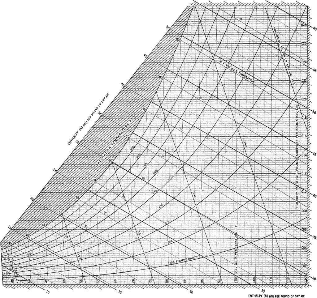
384 PSYCHROMETRIC CHART

385 100 LB 1 LB 1 1 PRESSURE = 1 PSI 1 1 PRESSURE = 100 PSI Figure Pressure is the force created by a substance per unit of area.
386 SLING PSYCHROMETER THERMOMETERS HANDLE WICK Figure A sling psychrometer is used to measure the wet bulb temperature of the air.
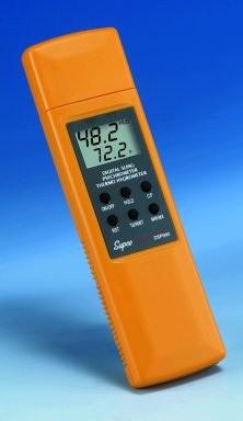

387
 Figure 1-11.")
388 AIR (70 F) 1 LB OF AIR (SATURATED) WATER VAPOR (110.5 GRAINS OR LB) AIR (70 F) 1 LB OF AIR (50% MOISTURE) WATER VAPOR (55.25 GRAINS OR LB) Figure Relative humidity is the amount of moisture in the air compared to the amount of moisture that it could hold if it were saturated.

389 HYGROMETERS INDICATOR SENSING ELEMENT SCALE DIMENSIONAL CHANGE Figure Hygrometers readings of relative humidity. ELECTRICAL IMPEDANCE measure and provide

390 THERMOMETERS STEM DIAL PROTECTIVE CASE F 200 F TO 1000 F RANGE Figure 1-9. Thermometers are used to measure temperature.
391 TEMPERATURE CONVERSION FAHRENHEIT TO CELSIUS CONVERSION Convert 72 F to Celsius. C = C = C = 212 F WATER BOILS 180 F RANGE 72 F = C F WATER FREEZES 32 F C = C FAHRENHEIT SCALE CELSIUS TO FAHRENHEIT CONVERSION WATER BOILS 100 C 100 C RANGE Convert 30 C to Fahrenheit. F = (1.8 x C ) C = 86 F F = (1.8 x 30) + 32 F = F = 86 F WATER FREEZES 0 C CELSIUS SCALE Figure 1-8. Temperature is commonly expressed by using the Fahrenheit or Celsius scale.

392 SPECIFIC HEAT* Solid Liquid Gas Aluminum.214 Alcohol Brass.09 Ammonia Air.24 Butane.377 Coal.3 Kerosene Concrete.156 Mineral oil.5 CO Chlorine.117 Glass.18 Gold.031 Petroleum.4 Helium R Methane.520 Ice.487 R Neon.246 Iron Rubber.12 Saltbrine.745 Oxygen Turpentine.42 Propane.375 Wood.45 Water Steam * in Btu/lb/ F Figure 1-7. Specific heat is the ability of material to hold heat. Values of specific heat are constants that are given in tables and charts.
393 HEAT TRANSFER METAL ROD HEAT FLOW CONDUCTION WARM REGION AIR CURRENT FLOW COOL REGION COOL REGION CONVECTION HEAT RADIANT ENERGY WAVES

394 LATENT HEAT 212 STEAM SENSIBLE HEAT CHANGE OF STATE LATENT HEAT WATER 32 0 CHANGE OF ICE STATE HEAT (IN BTU) 1310 Figure 1-5. Sensible heat raises the temperature of a sub- stance. Latent heat causes the substance to change state.

395 VENTILATION OUTSIDE AIR IN HIGH-EFFICIENCY FILTRATION DEVICE CLEAN SUPPLY AIR SPACE AIR HANDLING UNIT A SPACE B Figure 1-4. Ventilation is the process of introducing fresh air into a building.
396 CIRCULATION COOLING COIL HEATING COIL SUPPLY AIR FILTER SUPPLY AIR FAN OUTSIDE AIR IN RETURN AIR SUPPLY DUCT RETURN DUCT CIRCULATING AIR SUPPLY AIR REGISTER SPACE A SPACE B RETURN AIR GRILLE Figure 1-3. Supply and return air ductwork is sized and located to provide efficient flow of air through building spaces.


397 HUMIDITY CONTROL WATER VAPOR NORMALLY CLOSED CONTROL VALVE SUPPLY AIR DUCT HUMIDIFIER DRY AIR SUPPLY AIR DUCT MOIST AIR WATER VAPOR PAN WATER TO DRAIN REFRIGERATION EVAPORATOR COIL REMOVES MOISTURE DEHUMIDIFIER Figure 1-2. Humidifiers and dehumidifiers control the level of humidity in a building.

398 GAS-FIRED BOILERS BOILER UTILITY PRESSURE REGULATING VALVE GAS TO BURNER UTILITY METER SECOND ARY AIR T O BURNER PLANT PRESSURE REGULATING VALVE GAS PILOT MAIN GAS VALVE MAIN GAS SHUTOFF COCK LOW GAS PRESSURE SWITCH PILOT GAS SOLENOID VALVES MAIN GAS VALVE HIGH GAS PRESSURE SWITCH PILOT PRESSURE REGULATOR PILOT PRESSURE GAUGE PILOT GAS LINE BUTTERFLY GAS VALVE Figure 3-3. In a gas-fired boiler application, natural gas is piped from a utility to a gas burner where it is used to heat water.

399 INDUCTION AIR HANDLING UNITS WINDOW HIGH-VELOCITY AIR FLOW HEATING COIL BUILDING SPACE AIR OUTSIDE WALL INDUCTION NOZZLE FILTER PLENUM HIGH-PRESSURE AIR IN DUCT FLOOR DUCT Figure Induction air handling units use highpressure air to force building space air across filters and heating coils.
 are the")
400 FUEL OXYGEN HEAT Figure 3-2. Fuel, oxygen, and ignition temperature (heat) are the three requirements for combustion.

401 FUEL OIL GRADES Characteristics No. 2 No. 4 No. 5 No. 6 Type light distillate light distillate or blend light residual residual Color amber black black black Specific Gravity Btu/gal. 141, , , ,000 Btu/lb 19,500 19,100 18,950 18,750 Figure 3-4. The American Society for Testing and Materials has established standards for grading fuel oils and their characteristics.
402 ROOM SENSOR ANALOG INPUTS DIGITAL OUTPUTS DIGITAL INPUTS BUILDING AUTOMATION SYSTEM CONTROLLER Z BUS 24 VAC ANALOG INPUTS DIGITAL INPUTS DIGITAL INPUTS DIGITALOUTPUTS DSI ZONE SENSOR MOUNTED ON WALL IN ROOM Figure 4-1. A sensor must be chosen to suit the application and located where it can properly sense the controlled variable.
403 HEAT PUMP COOLING CYCLE COMPRESSOR REVERSING VALVE SPOOL INDOOR UNIT OUTDOOR UNIT EXPANSION DEVICE WARM AIR FROM BUILDING SPACE COOL AIR TO BUILDING SPACE WARM OUTSIDE AIR HOT OUTSIDE AIR Figure The mechanical equipment of a heat pump sys- tem can be used to transfer heat from the air inside a building to the air outside a building, producing a cooling effect.

404 LITHIUM BROMIDE-WATER ABSORPTION REFRIGERATION SYSTEM REFRIGERANT VAPOR TO COOLING TOWER SEPARATOR FROM COOLING TOWER HEAT FROM HEAT SOURCE CONDENSER GENERATOR HEAT EXCHANGER EXPANSION VALVE LIQUID REFRIGERANT PUMP WARM WATER FROM BUILDING SPACE COOLED LITHIUM BROMIDE SOLUTION ABSORBER REFRIGERANT VAPOR EVAPORATOR COIL CHILLED WATER TO BUILDING SPACE HEAT EXCHANGER CHILLER Figure Absorption refrigeration systems are commonly used for large commercial or industrial applications where mechanical compression systems are not as efficient.
405 LIQUID CHILLER AIR OUTLET CONDENSER WATER PUMP COOLING TOWER WARM WATER OUT (95 F) CONDENSER (TUBE-IN-SHELL HEAT EXCHANGER) COOL WATER IN (85 F) REFRIGERANT FLOW HOT WATER INLET COMPRESSOR AIR INLET LOUVERS EXPANSION DEVICE EVAPORATOR (TUBE-IN-SHELL HEAT EXCHANGER) CWR (52 F) CWS (42 F) LIQUID CHILLER COLD WATER USED FOR COOLING COOL WATER COLLECTION Figure A liquid chiller contains two tube-in-shell heat exchangers that transfer heat to and from water.
406 REFRIGERATION SYSTEM REFRIGERANT ENTERS EVAPORATOR 68.5 PSIG, 40 F, 34.4 BTU/LB EXPANSION DEVICE 60 F 80 F REFRIGERANT LEAVES CONDENSER PSIG, 95 F, 34.4 BTU/LB 80 F LIQUID LINE 95 F HOT GAS DISCHARGE LINE EVAPORATOR REFRIGERANT LEAVES EVAPORATOR 68.5 PSIG, 52 F, BTU/LB CONDENSER SUCTION LINE COMPRESSOR/MOTOR REFRIGERANT ENTERS CONDENSER PSIG, 140 F, BTU/LB REFRIGERANT LEAVES COMPRESSOR PSIG, 182 F, 123 BTU/LB Figure 3-9. Electricity is used in a refrigeration system to power an electric motor in a compressor, which produces a refrigeration effect used to cool building spaces.

407 RETURN AIR DAMPERS CLOSED AIR FROM BUILDING SPACES EXHAUST AIR DAMPERS OPEN OUTSIDE AIR (55 F) FILTER SUPPLY FAN OUTSIDE AIR DAMPERS AIR TO BUILDING SPACES OPEN Figure 3-8. Free cooling uses outside air to cool build- ing spaces.

408 HEAT PUMP HEATING CYCLE COMPRESSOR REVERSING VALVE SPOOL INDOOR UNIT OUTDOOR UNIT EXPANSION DEVICE COOL AIR WARM AIR TO BUILDING SPACE COOL AIR IN COLD AIR OUT Figure 3-7. In a heat pump heating cycle, heat is collected from the outdoor air at the outdoor coil and released to the building space at the indoor coil.

409 SOLAR COLLECTOR ON ROOF HOT WATER STORAGE TANK HOT OUT CIRCULATING PUMP WATER COLD WATER IN Figure 3-6. Solar collection systems may be used to heat water which is stored and then used to heat building spaces.
410 FUEL OIL SYSTEM ATOMIZING AIR BURNER NOZZLE NOZZLE AIR PRESSURE GAUGE MAIN FUEL OIL SOLENOID VALVES ATOMIZING AIR PRESSURE FEEDBACK CONTROL TUBING FUEL OIL BURNER PRESSURE GAUGE FUEL OIL PRESSURE GAUGE FUEL OIL PRESSURE REGULATOR FUEL OIL RELIEF VALVE SHUT OFF VA LVE FUEL OIL STRAINER FUEL OIL STRAINER FUEL OIL PUMP FUEL OIL RETURNED TO TANK FUEL OIL FROM T ANK CHECK VALVE FUEL OIL THERMOMETER Figure 3-5. A fuel oil system includes the accessories required to safely and efficiently operate the fuel oil burner.
411 SETPOINT ADJUSTMENT SCREW THROTTLING RANGE ADJUSTMENT SLIDER Figure 4-2. A controller receives a signal from the sensor, compares it to a setpoint value, and sends an appropriate output signal to a controlled device.
412 EXHAUST AIR DAMPERS OPEN RETURN AIR DAMPERS CLOSED FILTER OUTSIDE AIR DAMPERS OPEN COOLING COIL SUPPLY FAN CHILLED WATER VALVE CLOSED Figure 4-5. Outside air may be used to cool building spaces.

413 Figure 4-4. Heating systems may use electronic combus- tion control devices to safely control combustion heating equipment.
414 CLOSED LOOP CONTROL DIRECT-ACTING THERMOSTAT FEEDBACK NORMALLY CLOSED HOT WATER VALVE Figure Closed loop control systems provide feedback to the controller.

415 Figure 5-1. Comfort is a requirement of occupants of mod- ern commercial buildings as a condition of leasing space.
416 CONTROL POINT OFFSET SETPOINT TIME HIGH OFFSET, LOW ACCURACY CONTROL POINT OFFSET SETPOINT TIME LOW OFFSET, HIGH ACCURACY Figure The smaller the difference between setpoint and control point (offset), the more accurate the control system.

417 HVAC HAZARDS DANGER HIGH VOLTAGE MECHANICAL ELECTRICAL CHEMICAL Figure HVAC control systems may include mechanical, electrical, and chemical hazards.
418 PROPORTIONAL CONTROL 100% 57 OUTPUT SIGNAL VARIES BETWEEN FULLY OPEN AND FULLY CLOSED 56 50% 55 SETPOINT 54 0% 53 TIME Figure In a proportional control system, the output signal varies between fully open and fully closed.
419 ON/OFF CONTROL ROOM TEMPERATURE DIFFERENTIAL SETPOINT CLOSED OPEN FURNACE CIRCUIT ON OFF THERMOSTAT Figure In an ON/OFF control system, the controlled device is either fully open or fully closed.
420 SAFETY RELIEF VALVES PRESSURE SWITCH SAFETY RECEIVER RELIEF VALVE Figure6-16. Safety relief valves prevent overpressurization of the air compressor receiver and parts of the air distribution system.

421 COOL AIR FLOW WARM AIR FAN MOTOR FLOW ELECTRIC HEATING ELEMENT Figure 3-1. Electric heating elements heat the air flowing through ductwork and delivered to the building spaces.

422 ROOM SENSOR ANALOG INPUTS DIGITAL OUTPUTS DIGITAL INPUTS BUILDING AUTOMATION SYSTEM CONTROLLER Z BUS 24 VAC ANALOG INPUTS DIGITAL INPUTS DIGITAL INPUTS DIGITALOUTPUTS DSI ZONE SENSOR MOUNTED ON WALL IN ROOM Figure 4-1. A sensor must be chosen to suit the application and located where it can properly sense the controlled variable.

423 SETPOINT ADJUSTMENT SCREW THROTTLING RANGE ADJUSTMENT SLIDER Figure 4-2. A controller receives a signal from the sensor, compares it to a setpoint value, and sends an appropriate output signal to a controlled device.

424 EXHAUST AIR DAMPERS OPEN RETURN AIR DAMPERS CLOSED FILTER OUTSIDE AIR DAMPERS OPEN COOLING COIL SUPPLY FAN CHILLED WATER VALVE CLOSED Figure 4-5. Outside air may be used to cool building spaces.

425 RETURN AIR TEMPERATURE CONTROL RETURN AIR DUCT RETURN AIR SENSOR EXHAUST AIR DAMPER CONTROLLER RETURN FAN BUILDING SPACE RETURN AIR DAMPER SUPPLY AIR DUCT OUTSIDE AIR DAMPER FILTER COOLING COIL SUPPLY FAN HUMIDIFIER HEATING COIL Figure 4-8. In return air temperature control, a sensor or controller is mounted in the common return duct in an air handling unit.

426 VOLUME CONTROL FAN HOUSING INLET VANES LINKAGES INLET VANE CRANK ARM ACTUATOR Figure 4-9. In volume control systems, supply fan air volume and required horsepower are reduced, saving a significant amount of energy and money over constantvolume systems.

427 HUMIDITY CONTROL EXHAUST AIR DAMPER RETURN FAN RETURN AIR DUCT BUILDING SPACE THERMOSTAT HUMIDISTAT RETURN AIR DAMPER SUPPLY AIR DUCT OUTSIDE AIR DAMPER FILTER COOLING COIL HEATING COIL SUPPLY FAN STEAM VALVE AIR FLOW SWITCH HUMIDIFIER Figure In humidity control, a humidity controller or sensor opens or closes a humidifier in the air stream to keep the humidity close to setpoint.
428 74 CONTROL POINT OFFSET 72 OFFSET SETPOINT 70 TIME Figure Offset is the difference between the actual variable (control point) and setpoint.

429 SYSTEM FEEDBACK CONTROLLED DEVICE ASSEMBLY INPUT SENSOR OUTPUT CONTROLLER ACTUATOR CONTROLLED DEVICE Figure Feedback is used to measure the results of the control system output. HVAC PROCESS FINAL CONDITION

430 CLOSED LOOP CONTROL DIRECT-ACTING THERMOSTAT FEEDBACK NORMALLY CLOSED HOT WATER VALVE Figure Closed loop control systems provide feedback to the controller.
431 OPEN LOOP CONTROL NO FEEDBACK REGARDING STATUS OF PUMP PUMP CONTACTOR OUTSIDE AIR THERMOSTAT SET AT 65 F CHILLER COMPRESSOR CHILLED WATER PUMP CHILLED SUPPLY WATER CHILLED RETURN WATER CHILLER EVAPORATOR (HEAT EXCHANGER) Figure Open loop control systems do not have feed- back between the controller, sensor, and controlled device.

432 ON/OFF CONTROL ROOM TEMPERATURE DIFFERENTIAL SETPOINT CLOSED OPEN FURNACE CIRCUIT ON OFF THERMOSTAT Figure In an ON/OFF control system, the controlled device is either fully open or fully closed.

433 PROPORTIONAL CONTROL 100% 57 OUTPUT SIGNAL VARIES BETWEEN FULLY OPEN AND FULLY CLOSED 56 50% 55 SETPOINT 54 0% 53 TIME Figure In a proportional control system, the output signal varies between fully open and fully closed.
, the more accurate the control system.")
434 CONTROL POINT OFFSET SETPOINT TIME HIGH OFFSET, LOW ACCURACY CONTROL POINT OFFSET SETPOINT TIME LOW OFFSET, HIGH ACCURACY Figure The smaller the difference between setpoint and control point (offset), the more accurate the control system.
435 PNEUMATIC CONTROL SYSTEMS TRANSMITTERS AND CONTROLLERS AIR COMPRESSOR STATION AUXILIARY DEVICES CONTROLLED DEVICES RELAY FILTER AND PRESSUREREDUCING STATION PIPED TO HEAT CONTROL ROOM THERMOSTAT CHILLED WATER VALVE (NO) PNEUMATIC/ ELECTRIC SWITCH N.O. RED C. YELLOW INTAKE TO FAN CIRCUIT ELECTRIC HEAT SWITCH R DRAIN REFRIGERATED AIR DRYER AIR COMPRESSOR BULB IN OA SOLENOID AIR VALVE EXHAUST REMOTE ELEMENT CONTROLLER S LOW-LIMIT CONTROLLER DAMPER ACTUATOR (NC) Figure 5-5. Pneumatic control systems include the air compressor station, transmitters and controllers, auxiliary devices, and controlled devices.

436 ELECTRONIC CONTROL SYSTEM S ELECTRONIC ROOM THERMOSTAT 24 VAC IN DC 18 VDC OUT 74 Thermostat POWER SUPPLY ELECTRONIC HEATING VALVE ELECTRONIC COOLING VALVE Figure 5-7. Electronic control systems commonly have supply voltages of 10 VDC, 12 VDC, or 18 VDC.

437 R1 R2 OUTPUT VOLTAGE TO CONTROLLED DEVICE (DAMPER OR VALVE ACTUATOR) R4 R3 TEMPERATURE SENSOR SETPOINT POTENTIOMETER INPUT VOLTAGE Figure 5-8. Resistive bridge circuits use fixed resistors and variable resistors to vary the output voltage to an actuator.

438 SYSTEM-POWERED CONTROL SYSTEM S SUPPLY DUCT DUCT PRESSURE TAP CEILING-MOUNT VAV TERMINAL BOX WITH BELLOWS AIR FILTER AIR EXHAUST SYSTEMPOWERED THERMOSTAT CEILING AIR TO BUILDING SPACE SETPOINT ADJUSTMENT LEVER Figure System-powered control systems are used in limited applications such as VAV terminal boxes.

439 HYBRID CONTROL SYSTEM ELECTRONIC CONTROL SYSTEM WIRING S TRANSDUCER PNEUMATIC CONTROL SYSTEM PIPING Figure Hybrid control systems include different HVAC control technologies to control a single HVAC unit.


440 ELECTRONIC INPUT WIRING ELECTRIC/ PNEUMATIC TRANSDUCER PNEUMATIC OUTPUT PIPING Figure Retrofitting requires the use of electric/pneu- matic transducers to enable one control technology to in- teract with another.

 Personal")
441 Electro Pneumatic Transducers Phone Jack Hybrid Main Control Panel Main air supply & Pressure gauge Modem Service Outlets Global I/O Terminal Board Power Supply Processing Boards Communication Board Communication Buss (Sub Panels) Personal Operator Terminal
442 AIR COMPRESSOR STATIONS AIR COMPRESSOR INTAKE AIR FILTER PRESSURE SWITCH SAFETY RELIEF VALVE PRESSURE REGULATOR WITH GAUGE ELECTRIC MOTOR AIR DRIER MAIN AIR TO SYSTEM FILTER/SEPARATOR WITH MANUAL DRAIN INSPECTION PORT RECEIVER FILTER/SEPARATOR AUTOMATIC DRAIN AUTOMATIC DRAIN WITH TO DRAIN PICTORIAL AIR COMPRESSOR INTAKE AIR FILTER PRESSURE SWITCH SAFETY RELIEF VALVE PRESSURE REGULATOR WITH GAUGE AIR DRIER MAIN AIR TO SYSTEM FILTER/SEPARATOR WITH MANUAL DRAIN FILTER/SEPARATOR WITH AUTOMATIC DRAIN RECEIVER AUTOMATIC DRAIN SCHEMATIC TO DRAIN
443 POSITIVE-DISPLACEMENT COMPRESSORS CYLINDER HEAD SUCTION VALVE SUCTION LINE FROM EVAPORATOR DISCHARGE VALVE DISCHARGE LINE TO CONDENSER CYLINDER PISTON CONNECTING ROD CRANKSHAFT SUCTION STROKE RECIPROCATING COMPRESSION STROKE
444 INLET PORT MALE ROTOR CAM RING ROTATION HOUSING SPRING ROTOR END BEARINGS SLOTS OUTLET PORT FEMALE ROTOR OUTLET PORT LOBES HOUSING INLET PORT FEMALE ROTOR MALE ROTOR ROTOR VANES HOUSING VANE SCREW ROTARY Figure 6-2. Reciprocating and rotary compressors are positive-displacement compressors that decrease the volume of the air to increase its pressure.

445 CENTRIFUGAL COMPRESSORS HOUSING OUTLET PORT DIFFUSER DRIVE SHAFT VANES INLET PORT CLOSED FACE IMPELLER Figure 6-3. Centrifugal compressors are dynamic compres- sors that add kinetic energy to accelerate air and convert the velocity energy to pressure energy with a diffuser.

446 AIRBORNE PARTICLES, DIRT, ETC. CLEAN OUTSIDE AIR OUTSIDE AIR INTAKE Figure 6-4. An outside air intake can reduce the particulate matter introduced to the air compressor.

447 AUTOMATIC DRAINS PIPING FROM RECEIVER PIPING TO FLOOR DRAIN AUTOMATIC DRAIN Figure 6-8. An automatic drain may include a timer-actuated valve to automatically remove moisture from a receiver at preset intervals.

448 MOIST INLET MOIST AIR OUTLET AIR EXHAUST PURGED TO ATMOSPHERE CHECK VALVES DRY AIR OUTLET PURGE VALVE DESICCANT MATERIAL DRIER OPERATING DRIER REACTIVATING Figure A desiccant drier removes moisture from the compressed air by adsorption.


449 REGULATOR ADJUSTMENT KNOB PRESSURE GAUGE PORT REGULATOR HOUSING OUTLET PORT INLET PORT SIGHT WINDOW FILTER HOUSING MANUAL DRAIN KMC Controls Figure Air line filters and pressure regulators can be combined into a single unit.

450 OIL REMOVAL FILTERS DIFFERENTIAL PRESSURE INDICATOR BODY GASKET BOWL O-RING FILTRATION ELEMENT AUTOMATIC DRAIN O-RING TRANSPARENT BOWL BOWL GUARD NUT Figure Regardless of the filter being used, its condition should be checked regularly, and the filtration element should be replaced when required.

451 PRESSURE SWITCHES COMPRESSOR RECEIVER MOTOR PRESSURE SWITCH Figure A pressure switch is mounted on the receiver and turns the compressor motor ON and OFF based on the pressure in the receiver.

452 PRESSURE REGULATORS PRESSURE REGULATOR LOCKNUT PRESSURE GAUGE Figure A pressure regulator allows a final adjustment of the air pressure to the controllers.

453 SAFETY RELIEF VALVES PRESSURE SWITCH SAFETY RECEIVER RELIEF VALVE Figure6-16. Safety relief valves prevent overpressurization of the air compressor receiver and parts of the air distribution system.

454 ALTERNATOR ALTERNATOR Figure An alternator operates one compressor dur- ing one pumping cycle and the other compressor during the next pumping cycle.

455 ACTUATORS ACTUATOR SHAFT SHAFT MOVEMENT ACTUATOR LINKAGE Figure 7-1. An actuator and linkage control damper position to regulate the temperature of a building space.

456 DAMPER AND VALVE ACTUATORS DAMPER LINKAGE DAMPER POSITIONER (OPTIONAL) DAMPER ACTUATOR Figure 7-2. Actuators may be damper or valve actuators.

457 SPRING VALVE ACTUATOR VALVE

458 ALUMINUM END CAP SCREW HOLES TO ATTACH TO ACTUATOR BODY AIR FITTING Figure 7-3. Caution must be used when removing the end cap from the actuator body because spring pressure on the end cap may cause it to separate suddenly.


459 DAMPERS ADJACENT BLADES ARE PARALLEL AND MOVE IN SAME DIRECTION Jackson Systems, LLC PARALLEL BLADE ADJACENT BLADES MOVE IN OPPOSITE DIRECTIONS OPPOSED BLADE Jackson Systems, LLC ROUND BLADE Figure Dampers are used in HVAC systems to con- trol the flow of air and include parallel, opposed, and round blade dampers.

460 DAMPER SEALS DAMPER BLADE SEAL DAMPER BLADE DAMPER BLADE PIN END SEAL BOTTOM SEAL Figure Damper seals provide a snug fit to minimize air leakage.

461 DAMPER BLADE LINKAGE DAMPER LUBRICATION POINTS DAMPER Figure Manufacturer-recommended lubricant is used at damper lubrication points.

462 HVAC CONTROL VALVE COMPONENTS PACKING NUT AIR FITTING PACKING GLAND PACKING PISTON CUP STEM PACKING SPRING DISC STEM AND PLUG ASSEMBLY FLANGE SEAT DISC HOLDER VALVE PLUG VALVE PORT VALVE BODY Figure HVAC control valve components include the valve body, stem, disc, and packing.


463 TWO-WAY VALVES AIR FITTING SPRING DIAPHRAGM PISTON PACKING NUT SPRING PACKING STEM DISC SEAT VALVE PLUG INLET INLET OUTLET Figure Two-way valves have one inlet and one outlet. OUTLET VALVE BODY
464 AIR PRESSURE REMOVED VALVE OPEN WHEN AIR PRESSURE REMOVED FROM VALVE HOT WATER IN HOT WATER OUT NORMALLY OPEN (FAIL OPEN) AIR PRESSURE REMOVED VALVE CLOSED WHEN AIR PRESSURE REMOVED FROM VALVE CHILLED WATER IN NORMALLY CLOSED (FAIL CLOSED)

465 DAMPER/VALVE APPLICATIONS NORMALLY CLOSED OUTSIDE AIR DAMPER LINKAGE MOVEMENT ON LOSS OF AIR FLOW DAMPER ACTUATOR NORMALLY CLOSED HUMIDIFIER VALVE DAMPER MOVEMENT WHEN ACTUATOR RETRACTS WATER VAPOR AIR FLOW SUPPLY AIR DUCT Figure Normally closed dampers and valves prevent excessively hot, cold, or humid air from being introduced into a building.
 VALVE PLUG OUTLET Figure 7-15.")
466 THREE-WAY VALVES SPRING AIR FITTING PACKING NUT SPRING STEM PACKING NORMALLY CLOSED INLET NORMALLY CLOSED INLET DISCS NORMALLY OPEN INLET NORMALLY OPEN INLET VALVE PLUG OUTLET (COMMON) VALVE PLUG OUTLET Figure Mixing valves have two inlets and one outlet, diverting valves have one inlet and two outlets.
467 VALVE STEM LIFT AND FLOW QUICKOPENING VALVE CURVE EQUAL PERCENTAGE VALVE CURVE LINEAR VALVE CURVE VALVE STEM LIFT (%) VALVE PLUG QUICKOPENING PLUG SHAPE LINEAR PLUG SHAPE EQUAL PERCENTAGE PLUG SHAPE Figure Valve flow characteristics vary based on the shape of the plug.

468 PACKING NUT PACKING GLAND PACKING LUBRICANT PACKING FOLLOWER FOLLOWER SPRING BONNET STEM AND DISC HOLDER ASSEMBLY DISC DISC SPRING PLUG VALVE BODY VALVE REBUILD KIT Figure Valve rebuild kits contain internal valve parts, packing material, and packing lubricant.

469 PACKING NUT PACKING VALVE STEM PACKING GLAND BONNET Figure Valves are repacked when the valve begins to leak excessively at the valve stem and packing gland.


470 THERMODYNAMICS PRODUCTS OF COMBUSTION THERMAL ENERGY REACTANTS AIR (OXYGEN AND NITROGEN) WATER VAPOR (H2 O) IGNITION TEMPERATURE HEAT FUEL (HYDROGEN AND CARBON) CARBON DIOXIDE (CO 2 ) COMBUSTION CHEMICAL ENERGY FIRST LAW OF THERMODYNAMICS LOW TEMPERATURE MATERIAL 75 F HEAT FLOW 600 F HIGH TEMPERATURE MATERIAL SECOND LAW OF THERMODYNAMICS FIRST LAW OF THERMODYNAMICS SECOND LAW OF THERMODYNAMICS COMBUSTION OF FUEL CONVERTS CHEMICAL ENERGY INTO THERMAL ENERGY HEAT FROM HOT GASES OF COMBUSTION FLOWS TO WATER IN BOILER Cleaver-Brooks BOILER THERMODYNAMICS Figure 1-4. The first law of thermodynamics states that the chemical energy in the reactants equals the thermal energy in the products. The second law of thermodynamics states that heat always flows from a material at a high temperature to a material at a low temperature.
 Figure 1-5. Sensible heat is heat measured with a thermometer or sensed by a person. Sensible heat does not involve a change of state.")
471 HEAT LATENT HEAT 212 STEAM SENSIBLE HEAT CHANGE OF STATE (WATER TURNS TO STEAM) LATENT HEAT 32 WATER ICE CHANGE OF STATE (ICE TURNS TO WATER) HEAT (BTU) ICE (SOLID) WATER (LIQUID) STEAM BUBBLES (GAS) Figure 1-5. Sensible heat is heat measured with a thermometer or sensed by a person. Sensible heat does not involve a change of state. Latent heat is heat identified by a change of state and no temperature change of the substance.
RSES Technical Institute Training Manual 3 72 hours, 72 NATE CEHs, 7.2 CEUs
 Lesson 1 - Basic Heat Pump Theory (Part 1) Describe the basic operation of a heat pump. Explain the function of various heat pump controls. Interpret the wiring diagrams and performance data provided by
AIR CONDITIONING. Carrier Corporation 2002 Cat. No
 AIR CONDITIONING Carrier Corporation 2002 Cat. No. 020-016 1. This refresher course covers topics contained in the AIR CONDITIONING specialty section of the North American Technician Excellence (NATE)
CHAPTER 4. HVAC DELIVERY SYSTEMS
 CHAPTER 4. HVAC DELIVERY SYSTEMS 4.1 Introduction 4.2 Centralized System versus Individual System 4.3 Heat Transfer Fluids 4.4 CAV versus VAV Systems 4.5 Common Systems for Heating and Cooling 4.6 Economizer
BOOK 1 OVERVIEW RD2XRT INSTALLATION AND OPERATION MANUAL. Table of Contents ABOUT BOOK 1:
 4510 Helgesen Drive, Madison, WI, 53718 608.221.4499, 800.627.4499, Fax: 608.221.2824 support@renewaire.com www.renewaire.com RD2XRT INSTALLATION AND OPERATION MANUAL BOOK 1 OVERVIEW ABOUT BOOK 1: This
BOOK 1 OVERVIEW RD2XIN INSTALLATION AND OPERATION MANUAL. Table of Contents ABOUT BOOK 1:
 4510 Helgesen Drive, Madison, WI, 53718 608.221.4499, 800.627.4499, Fax: 608.221.2824 support@renewaire.com www.renewaire.com RD2XIN INSTALLATION AND OPERATION MANUAL BOOK 1 OVERVIEW ABOUT BOOK 1: This
AIR-CONDITIONING SYSTEMS AND APPLICATIONS. Abdullah Nuhait Ph D. King Saud University
 AIR-CONDITIONING SYSTEMS AND APPLICATIONS Abdullah Nuhait Ph D. King Saud University AIR-CONDITIONING SYSTEMS Earliest air conditioning system used only for heating (winter) Provided heated air for comfort
Use this Construction/HVAC Glossary to answer the questions below.
 www.garyklinka.com Page 1 of 21 Instructions: 1. Print these pages. 2. Circle the correct answers and transfer to the answer sheet on the second last page. 3. Page down to the last page for the verification
Math. The latent heat of fusion for water is 144 BTU s Per Lb. The latent heat of vaporization for water is 970 Btu s per Lb.
 HVAC Math The latent heat of fusion for water is 144 BTU s Per Lb. The latent heat of vaporization for water is 970 Btu s per Lb. Math F. to C. Conversion = (f-32)*(5/9) C. to F. Conversion = C * 9/5 +
Pharmaceutical Facility Design
 PhEn-602 Pharmaceutical Facility Design J. Manfredi Notes 9A PhEn-602 J. Manfredi 1 Primary & Secondary HVAC units Primary Primary air handling unit arrangement: One unit is responsible for all of the
Appendix 13. Categories of Cooling and Heating systems
 EcoShopping - Energy efficient & Cost competitive retrofitting solutions for Shopping buildings Co-funded by the European Commission within the 7 th Framework Programme. Grant Agreement no: 609180. 2013-09-01
College of Technological Studies Department of Power & Refrigeration Technology. Course Contents
 College of Technological Studies Department of Power & Refrigeration Technology Course Contents Course Designation: Air Conditioning Control systems Course No. : 272 0463 Credit Hrs.: 3 Lecture Hrs.: 2
Appendix A. Glossary of Common Terms
 Glossary of Common Terms Glossary of Common Terms Absorption chiller A refrigeration machine using heat as the power input to generate chilled water. Adjustable speed drive A means of changing the speed
A hydronic system controls comfort by delivering heated or cooled fluid to the conditioned space through pipes.
 Introduction to Hydronics A hydronic system controls comfort by delivering heated or cooled fluid to the conditioned space through pipes. Hydronic heating systems use hot water or steam to deliver the
PRESSURE-ENTHALPY CHARTS AND THEIR USE By: Dr. Ralph C. Downing E.I. du Pont de Nemours & Co., Inc. Freon Products Division
 INTRODUCTION PRESSURE-ENTHALPY CHARTS AND THEIR USE The refrigerant in a refrigeration system, regardless of type, is present in two different states. It is present as liquid and as vapor (or gas). During
Experienced Worker Assessment Blueprint HVAC - Heating, Ventilation and Air Conditioning
 Blueprint HVAC - Heating, Ventilation and Air Conditioning Test Code: 0144 / Version: 02 Specific Competencies and Skills Tested in this Assessment: Electricity Demonstrate understanding of basic AC/DC
TECHNICAL BULLETIN SELECTING A COMPRESSED AIR DRYER INTRODUCTION
 TECHNICAL BULLETIN SELECTING A COMPRESSED AIR DRYER INTRODUCTION Having an understanding of why water forms in your compressed air piping system will help you in evaluating the type of air drying system
Chapter-8 Capacity Control of Refrigeration Systems
 Chapter-8 Capacity Control of Refrigeration Systems Chapter-8 Capacity Control of Refrigeration Systems ၈.၁ Compressor Control Chiller Control and Chilled Water Plant Control Refrigeration system control
Energy Management and Controls
 As with the Chapter Review Tests and the Final Exam, the tests your understanding of the materials underlying the learning objectives. After you ve reviewed your answers to the Chapter Review Tests, try
Explanation of Cooling and Air Conditioning Terminology for IT Professionals
 Explanation of Cooling and Air Conditioning Terminology for IT Professionals White Paper #11 Revision 1 Executive Summary As power densities continue to increase in today s data centers, heat removal is
2. CURRICULUM. Sl. No.
 . CURRICULUM Sl. No. Code Title No. of Lecture Hours 1 RAC 001 Fundamentals of Refrigeration and Air 60 conditioning RAC 00 Psychrometry, Heat load Estimation for 70 Air conditioning and Refrigeration
INTRODUCTION HVAC BASICS AND HVAC SYSTEM EFFICIENCY IMPROVEMENT SECTION O 4/19/2012
 HVAC BASICS AND HVAC SYSTEM EFFICIENCY IMPROVEMENT SECTION O INTRODUCTION HVAC systems or Heating, Ventilating and Air-Conditioning systems control the environment for people and equipment in our facilities.
SECTION 8 AIR SOURCE HEAT PUMPS UNIT 43 AIR SOURCE HEAT PUMPS
 SECTION 8 AIR SOURCE HEAT PUMPS UNIT 43 AIR SOURCE HEAT PUMPS UNIT OBJECTIVES After studying this unit, the reader should be able to Describe the operation of reverse-cycle refrigeration (heat pumps) Explain
ENCLOSURE COOLING. Glossary
 ENCLOSURE COOLING Glossary Contents INTRODUCTION... 3 TYPES OF COOLING EQUIPMENT... 4 COOLING EQUIPMENT COMPONENTS... 5 ESSENTIAL COOLING S... 8 COOLING EQUIPMENT ACCESSORIES... 13 EQUIPMENT THAT NEEDS
HEAT PUMPS. Carrier Corporation GT72-01 Cat. No
 HEAT PUMPS Carrier Corporation 2003 GT72-01 Cat. No. 020-018 1. This refresher course covers topics contained in the HEAT PUMPS specialty section of the North American Technician Excellence (NATE) certification
SYNOPSIS. Part-Load Control Strategies for Packaged Rooftop Units. In this issue... Bin Hour Profile Charlotte, NC
 VOLUME ONE NUMBER THREE SYNOPSIS A N H V A C N E W S L E T T E R F O R B U I L D I N G O W N E R S A N D M A N A G E R S In this issue... Part-Load Strategies Why they re important.......... 1 What Things
Topic 2. ME 414/514 HVAC Systems Overview Topic 2. Equipment. Outline
 ME 414/514 HVAC Systems Overview Equipment Outline 2-1 The Complete System 2-2 The Air-Conditioning and Distribution System 2-3 Mechanical Equipment Air-handling Equipment Heating Equipment Boilers Furnaces
Refrigeration Systems and Accessories
 As with the Chapter Review Tests and the Final Exam, the tests your understanding of the materials underlying the learning objectives. After you ve reviewed your answers to the Chapter Review Tests, try
Thomas J Kelly. Fundamentals of Refrigeration. Sr. Engineering Instructor Carrier Corporation. August 20, Page number: 1.
 Thomas J Kelly Sr. Engineering Instructor Carrier Corporation August 20, 2003 1 SESSION OBJECTIVES At the conclusion of this session you should be able to: 1. Describe the basics principles of refrigeration
Digital Precise Air Control - DPAC
 Digital Precise Air Control - DPAC Mode Enable Sensor Options The temperature of this sensor will determine if the unit is in heating, cooling or vent mode during Occupied operation. The following options
RSES Technical Institute Training Manual 2 72 hours, 72 NATE CEHs, 7.2 CEUs
 Lesson 1 - Trade Tools Explain the importance of using proper tools and test instruments. List the various types of wrenches and describe their use. Describe the proper procedures for bending, flaring,
Air Conditioning Clinic
 Air Conditioning Clinic Psychrometry One of the Fundamental Series D C B A C B D A July 2012 TRG-TRC001-EN Psychrometry One of the Fundamental Series A publication of Trane Preface Psychrometry A Trane
Heat pump and energy recovery systems
 SBS5311 HVACR II http://ibse.hk/sbs5311/ Heat pump and energy recovery systems Ir. Dr. Sam C. M. Hui Faculty of Science and Technology E-mail: cmhui@vtc.edu.hk Oct 2017 Contents Basic concepts Air-to-air
SECTION SEQUENCE OF OPERATIONS FOR HVAC CONTROLS
 PART 1 - GENERAL SECTION 23 09 93 SEQUENCE OF OPERATIONS FOR HVAC CONTROLS 1.1 SUMMARY A. This Section includes control sequences for HVAC systems, subsystems, and other equipment. B. See Division 23 Section
For an ideal gas mixture, Dalton s law states that the sum of the partial pressures of the individual components is equal to the total pressure.
 1 PSYCHROMETICS Psychrometry is the study of the characteristics of moist air. We will see soon that evaporation of moisture from the skin can have a significant impact on thermal comfort. The rate of
Psychrometrics. Outline. Psychrometrics. What is psychrometrics? Psychrometrics in daily life and food industry Psychrometric chart
 Psychrometrics Outline What is psychrometrics? Psychrometrics in daily life and food industry Psychrometric chart Dry bulb temperature, wet bulb temperature, absolute humidity, relative humidity, specific
Engineering Guide VAV Diffusers. Please refer to the Price Engineer s HVAC Handbook for more information on VAV Diffusers.
 VAV Diffusers lease refer to the rice Engineer s HVAC Handbook for more information on VAV Diffusers. Diffuser Types Ceiling Diffusers Conventional air distribution systems typically group several rooms
For an administrative fee of $9.97, you can get an un-locked, printable version of this book.
 The System Evaluation Manual and Chiller Evaluation Manual have been revised and combined into this new book; the Air Conditioning and Refrigeration System Evaluation Guide. For an administrative fee of
HVAC Mandatory Provisions Part II, Page 1
 HVAC Mandatory Provisions Part II, Page 1 Mandatory Equipment Efficiency Worksheet (6.4.1.1) System Equipment Type Size Category (Tables 6.8.1A through K) Sub-Category or Rating Condition Units of Efficiency
Capt. Tim s s Duct Design Mythbusters. The bitterness of poor quality is remembered long after the sweetness of low price is forgotten!
 Capt. Tim s s Duct Design Mythbusters The bitterness of poor quality is remembered long after the sweetness of low price is forgotten! WHY CARE ABOUT THE DUCTS? Human Comfort Zone (After All, it s s only
SECTION SEQUENCE OF OPERATIONS FOR HVAC CONTROLS
 SECTION 23 09 93 SEQUENCE OF OPERATIONS FOR HVAC CONTROLS PART 1 - GENERAL 1.1 SUMMARY A. This Section includes control sequences for HVAC systems, subsystems, and equipment. B. See Division 23 Section
Energy Use in Refrigeration Systems
 2012 Rocky Mountain ASHRAE Technical Conference Energy Use in Refrigeration Systems PRESENTED BY: Scott Martin, PE, LEED AP BD+C Objectives Understand mechanical refrigeration terms Describe how heat is
D-PAC. Digital Precise Air Control System. Functionality Factory Testing Ease of Installation Ease of Maintenance Energy Efficiency
 Digital Precise Air Control System D-PAC Functionality Factory Testing Ease of Installation Ease of Maintenance Energy Efficiency AAON 24 South Yukon Avenue Tulsa, Oklahoma 747 (918) 583-2266 Fax (918)
Technical Development Program
 Technical Development Program PRESENTED BY: James Parker Insert your logo here AIR HANDLERS Coils: Direct Expansion Chilled Water and Heating Menu Section 1 Introduction Section 2 Typical Coil Applications
Air Conditioning Clinic. Absorption Water Chillers One of the Equipment Series TRG-TRC011-EN
 Air Conditioning Clinic Absorption Water Chillers One of the Equipment Series TRG-TRC011-EN Absorption Water Chillers One of the Equipment Series A publication of The Trane Company Worldwide Applied Systems
Armstrong Cool-Fog Systems
 Armstrong Cool-Fog Systems Armstrong International, Inc. is a leading supplier of hydropneumatic fogging systems used for both humidification and evaporative cooling. Its systems were first developed in
DEFROSTING METHODS Adapted from material originally provided by Kenneth S. Franklin, C.M., Director of Service, Hussmann Corporation
 EVAPORATOR DEFROSTING: WHEN AND WHY The refrigeration evaporator is a container that provides room for the evaporating refrigerant. The refrigerant receives heat by conduction through the walls of the
AND AIR-CONDITIONING. Dr Ali Jawarneh Department of Mechanical Engineering Hashemite University
 Chapter 14 GAS VAPOR MIXTURES AND AIR-CONDITIONING Dr Ali Jawarneh Department of Mechanical Engineering Hashemite University 2 Objectives Differentiate between dry air and atmospheric air. Define and calculate
B. A. T. Basic Appliance Training
 B. A. T. Basic Appliance Training BASIC REFRIGERATION presented by Phil Whitehead Program Objective The objective of this program is to give you some of the basic elements that are essential to understanding
Summary Comparison of Simulation Program Features
 Summary Comparison of Simulation Program Features FEATURE DOE2.2 equest TRACE 700 HAP Public/Proprietary Public Domain Proprietary Proprietary Proprietary Simulation Method 8760 hours 8760 hours 8760 hours
Introduction to HVAC. American Standard Inc Air Conditioning Clinic TRG-TRC018-EN
 Introduction to HVAC Agenda Psychrometrics Human Comfort Heat Transfer Refrigeration Cycle HVAC Terminology HVAC Systems Introduction to HVAC Psychrometrics 2000 TRG-TRC002-EN Properties of Air Dry-bulb
Energy Impacts of Compressed Air
 The Overlooked: Water 101/Plug Loads/Process Energy Impacts of Compressed Air Rusty Friend AMEC Foster Wheeler August 14, 2017 Tampa Convention Center Tampa, Florida Energy Impacts of Compressed Air Energy
A. Base Bid: 1. Heating Contractor provide: a. Control sequences for HVAC systems, subsystems, and equipment.
 SECTION 23 09 93 - SEQUENCE OF OPERATIONS FOR HVAC CONTROLS PART 1 - GENERAL 1 WORK INCLUDES A. Base Bid: Heating Contractor provide: Control sequences for HVAC systems, subsystems, and equipment. B. Alternate
Short Questions with Answers APPLIED THERMODYNAMICS(5 TH MECHANICAL) Chapter No-1
 Chapter No-1") Short Questions with Answers APPLIED THERMODYNAMICS(5 TH MECHANICAL) Chapter No-1 1. Define mechanical efficiency in case of an IC engine? [2015w] Ans. Mechanical efficiency of an I.C. engine is defined
Short Questions with Answers APPLIED THERMODYNAMICS(5 TH MECHANICAL) Chapter No-1 1. Define mechanical efficiency in case of an IC engine? [2015w] Ans. Mechanical efficiency of an I.C. engine is defined
BASIC HEAT PUMP THEORY By: Lloyd A. Mullen By: Lloyd G. Williams Service Department, York Division, Borg-Warner Corporation
 INTRODUCTION In recent years air conditioning industry technology has advanced rapidly. An important byproduct of this growth has been development of the heat pump. Altogether too much mystery has surrounded
Energy Recovery Ventilation
 Published on Business Energy Advisor (https://oncor.bizenergyadvisor.com) Home > Energy Recovery Ventilation Energy Recovery Ventilation Proper ventilation is essential for maintaining good indoor-air
Permission granted to reproduce for educational use only. Describe the problems caused by excess
 Chapter 16 Conditioning and Distribution of Compressed Air Controlling Dirt, Moisture, Temperature, and Pressure 1 Objectives Compare the various methods used to remove dirt from ambient air entering the
SECTION 5 COMMERCIAL REFRIGERATION UNIT 21 EVAPORATORS AND THE REFRIGERATION SYSTEM UNIT OBJECTIVES 3/22/2012 REFRIGERATION
 SECTION 5 COMMERCIAL REFRIGERATION UNIT 21 EVAPORATORS AND THE REFRIGERATION SYSTEM UNIT OBJECTIVES After studying this unit, the reader should be able to Define high-, medium-, and low-temperature refrigeration.
SECTION 3 BASIC AUTOMATIC CONTROLS UNIT 16 ADVANCED AUTOMATIC CONTROLS DIRECT DIGITAL CONTROLS (DDCS) AND PNEUMATICS
 AND PNEUMATICS") SECTION 3 BASIC AUTOMATIC CONTROLS UNIT 16 ADVANCED AUTOMATIC CONTROLS DIRECT DIGITAL CONTROLS (DDCS) AND PNEUMATICS UNIT OBJECTIVES After studying this unit, the reader should be able to Recognize advanced
SECTION 3 BASIC AUTOMATIC CONTROLS UNIT 16 ADVANCED AUTOMATIC CONTROLS DIRECT DIGITAL CONTROLS (DDCS) AND PNEUMATICS UNIT OBJECTIVES After studying this unit, the reader should be able to Recognize advanced
Refrigeration Technology in Building Services Engineering
 Unit 70: Unit code: T/600/0459 QCF Level: 3 Credit value: 10 Guided learning hours: 60 Unit aim Refrigeration Technology in Building Services Engineering This unit develops an understanding of the principles,
ME 410 MECHANICAL ENGINEERING SYSTEMS LABORATORY MASS & ENERGY BALANCES IN PSYCHROMETRIC PROCESSES EXPERIMENT 3
 ME 410 MECHANICAL ENGINEERING SYSTEMS LABORATORY MASS & ENERGY BALANCES IN PSYCHROMETRIC PROCESSES EXPERIMENT 3 1. OBJECTIVE The objective of this experiment is to observe four basic psychrometric processes
Comfort and health-indoor air quality
 Comfort and health-indoor air quality 1 The human body has a complicated regulating system to maintain the human body temperature constant most of the time, which is 98.6 F (36.9 C) regardless of the environmental
ZERO AIR GENERATOR MODEL 7000 INSTRUCTION MANUAL
 ZERO AIR GENERATOR MODEL 7000 INSTRUCTION MANUAL UNPACKING Connect the intake filter to the Air In port as shown below. Use Teflon tape on filter thread if not supplied on the fitting. POWER The ZAG is
SECTION THIRTEEN HEATING, VENTILATION, AND AIR CONDITIONING
 Source: BUILDING DESIGN AND CONSTRUCTION HANDBOOK SECTION THIRTEEN HEATING, VENTILATION, AND AIR CONDITIONING Lawrence E. McCabe* Chief Engineer Mechanical STV Group Douglassville, Pennsylvania The necessity
UNIVERSITY OF MISSOURI Heating Ventilating and Air-Conditioning (HVAC) 2016 Q1
 2016 Q1") GENERAL: This section provides general standards for overall sizing and design of Heating, Ventilating, and Air Conditioning (HVAC) systems. Other sections contain specific standards for each system per
GENERAL: This section provides general standards for overall sizing and design of Heating, Ventilating, and Air Conditioning (HVAC) systems. Other sections contain specific standards for each system per
State of the art building simulation software... Frenger Radiant chilled beam performance at 1 Shelly St - Sydney
 Frenger Radiant chilled beam performance at 3D Model Creation Daylight Analysis Comparison of the performance of various HVAC systems at 1 Shelly St, Sydney VAV fancoil Active chilled beam Passive chilled
Technical Development Program COMMERCIAL HVAC SYSTEMS. Water Source Heat Pump Systems PRESENTED BY: Ray Chow. Sales Engineer
 Technical Development Program PRESENTED BY: COMMERCIAL HVAC SYSTEMS Water Source Heat Pump Systems Ray Chow Sales Engineer TDP Updates Menu Section 1 Section 2 Section 3 Section 4 Section 5 Section 6 Section
Jet Compressors. Circulate Steam Boost Low-Pressure Steam Compress and Mix Gases in Desired Proportion
 s Circulate Steam Boost Low- Steam Compress and Mix Gases in Desired Proportion S&K s are used in the process, paper, petroleum, power, gas, and other industries to circulate steam, boost low-pressure
Unit THE NATURE OF HEAT
 Unit 5.0 - THE NATURE OF HEAT Heat is a form of energy, in the form of infrared radiation. Heat from the sun travels through space at the speed of 300,000,000 m/s. Upon arriving on earth, much of the radiant
To accomplish this, the refrigerant fi tis pumped throughh aclosed looped pipe system.
 Basics Refrigeration is the removal of heat from a material or space, so that it s temperature is lower than that of it s surroundings. When refrigerant absorbs the unwanted heat, this raises the refrigerant
FAST AND ROBUST BUILDING SIMULATION SOFTWARE. Chilled Beam Performance: 1 Shelly Street, Sydney
 FAST AND ROBUST BUILDING SIMULATION SOFTWARE Chilled Beam Performance: 1 Shelly Street, Sydney 3D Model Creation 1 Shelley Street, Sydney 3D Model Creation 1 Shelley Street, Sydney Daylight Analysis 1
PREVIEW COPY. Compressors. Table of Contents. Introduction to Compressors...3. Lesson Two Reciprocating Compressors...21
 Compressors Table of Contents Lesson One Introduction to Compressors...3 Lesson Two Reciprocating Compressors...21 Lesson Three Rotary, Helical, and Scroll Compressors...37 Lesson Four Centrifugal Compressors...51
MECHANICAL ENGINEERING ME.2017 FUNDAMENTAL OF REFRIGERATION AND AIR CONDITIONING. Sample Questions and Answers
 MECHANICAL ENGINEERING ME.2017 FUNDAMENTAL OF REFRIGERATION AND AIR CONDITIONING Sample Questions and Answers CHAPTER 5 EVAPORATORS 1. What is Evaporator? Classify the various types of evaporator. Evaporator
Job Name Control Systems Description Date
 Job Name Control Systems Description Date Project Overview The project is a describe the building and its major HVAC systems (e.g. three-story office building, served by a rooftop unit VAV system ). In
How about Savings in Time, Money, Energy and Longer Life?
 Chapter 17: The Value of Maintaining Evaporative Cooling Equipment 97 The Value 17 of Maintaining Evaporative Cooling Equipment 1. Cooling Tower Maintenance and Upgrades... What s in it for You? How about
HVAC (Heating, Ventilating, and Air Conditioning)
") HVAC (Heating, Ventilating, and Air Conditioning) Gas vapor Mixtures The term vapor implies a gaseous state that is close to the saturation region of the substance, raising the possibility of condensation
HVAC (Heating, Ventilating, and Air Conditioning) Gas vapor Mixtures The term vapor implies a gaseous state that is close to the saturation region of the substance, raising the possibility of condensation
2009 IECC Commercial Mechanical Requirements
 BUILDING ENERGY CODES UNIVERSITY 2009 IECC Commercial Mechanical Requirements Ken Baker PNNL-SA-66171 Learning(Objec-ves(( ( 1. Find(minimum(equipment(efficiency(requirements( and(recite(at(least(3(common(terms(for(measuring(
PNEUMATIC & HYDRAULIC SYSTEMS
 PNEUMATIC & HYDRAULIC SYSTEMS CHAPTER THREE AIR GENERATION, TREATMENT & DISTREBUTION Dr. Ibrahim Naimi Air preparation For the continuing performance of control systems and working elements it is necessary
Chapter 10. Passive Cooling Contents
 Chapter 10. Passive Cooling Contents 10.1 Introduction to Cooling 10.2 Historical and Indigenous Use of Passive Cooling 10.3 Passive Cooling Systems 10.4 Comfort Ventilation VS Night Flush Cooling 10.5
Air Conditioning Clinic
 Air Conditioning Clinic VAV Systems One of the Systems Series July 2012 TRG-TRC014-EN VAV Systems One of the Systems Series A publication of Trane Preface VAV Systems A Trane Air Conditioning Clinic Figure
Institute of Aeronautical Engineering (Autonomous) Dundigal, Hyderabad B.Tech (III II SEM) MECHANICAL ENGINEERING
 Dundigal, Hyderabad B.Tech (III II SEM) MECHANICAL ENGINEERING") Institute of Aeronautical Engineering (Autonomous) Dundigal, Hyderabad- 500 043 B.Tech (III II SEM) MECHANICAL ENGINEERING REFRIGERATION AND AIR CONDITIONING Prepared by, Dr. CH V K N S N Moorthy, Professor
Institute of Aeronautical Engineering (Autonomous) Dundigal, Hyderabad- 500 043 B.Tech (III II SEM) MECHANICAL ENGINEERING REFRIGERATION AND AIR CONDITIONING Prepared by, Dr. CH V K N S N Moorthy, Professor
HVAC CONTROLS INTRODUCTION
 t.a.c. HVAC CONTROLS INTRODUCTION FOR INFORMATION ON TAC PRODUCTS AND TRAINING; http://ibsa-training.invensys.com/ FOR GENERAL INFORMATION ON TAC ; http://www.invensysibs.com/ Printed in U.S.A. 2006 F-26962-3
Single Zone System. One duct system Used mostly in small buildings Forced air system All spaces controlled by a single thermostat Single air return
 Single Zone System One duct system Used mostly in small buildings Forced air system All spaces controlled by a single thermostat Single air return Multi Zone System Used in small to medium sized buildings
MECHANICAL SCIENCE Module 2 Heat Exchangers
 Department of Energy Fundamentals Handbook MECHANICAL SCIENCE Module 2 Heat Exchangers Heat Exchangers DOE-HDBK-1018/1-93 TABLE OF CONTENTS TABLE OF CONTENTS LIST OF FIGURES... ii LIST OF TABLES... iii
IAQ: Re-tuning Commercial Buildings
 IAQ: Re-tuning Commercial Buildings A low-cost path to improved air quality and energy efficiency. B y S c o t t G o r d o n, C M All images courtesy of Johnson Controls Service. 10 RSES Journal FEBRUARY
ASHRAE JOURNAL ON REHEAT
 Page: 1 of 7 ASHRAE JOURNAL ON REHEAT Dan Int-Hout Chief Engineer Page: 2 of 7 Overhead Heating: A lost art. March 2007 ASHRAE Journal Article Dan Int-Hout Chief Engineer, Krueger VAV terminals provide
Technical Instructions Document No March 11, Air Compressor and Accessories. Description. Air Compressor Selection
 Document No. 155-002 Air Compressor and Accessories Description Air Compressor Selection Proper operation of pneumatic control systems requires a supply of clean, dry, oil-free air as the primary power
Table of Contents. Table of Contents Introduction... Intro-1
 Table of Contents Table of Contents...1-3 Introduction... Intro-1 Chapter 1 Chapter 2 Chapter 3 Chapter 4 Chapter 5 Chapter 6 Chapter 7 Chapter 8 Chapter 9 Chapter 10 Chapter 11 Chapter 12 Air Conditioning
A/C-HEATER SYSTEM - MANUAL
 A/C-HEATER SYSTEM - MANUAL 1986 Isuzu Trooper II 1986 A/C-HEATER SYSTEM Isuzu A/C-Heater Systems - Manual P UP, Trooper II * PLEASE READ THIS FIRST * CAUTION: When discharging air conditioning system,
Session: HVAC 101 HVAC 101. Steve Sain Sain Engineering Associates, Inc. August 9, Rhode Island Convention Center Providence, Rhode Island
 Session: HVAC 101 HVAC 101 Steve Sain Sain Engineering Associates, Inc. August 9, 2016 Rhode Island Convention Center Providence, Rhode Island Why? 2 Acknowledgements 3 Disclaimer I m gonna shoot down
Chapter 2.3: Steam System
 Part I: Objective type Questions and Answers Chapter 2.3: Steam System 1. For industrial process heating, the best quality of steam is: a) dry saturated steam b) superheated steam c) wet steam d) high
CONTENTS. Air Conditioning Fundamentals TC S
 LEVEL F Air Conditioning Fundamentals SG Mazda Motor Corporation Technical Service Training CONTENTS 1 INTRODUCTION Overview... 1 Audience and Purpose... 1 Content and Objectives... 2 How to Use This Guide...
Reinventing Energy Efficiency
 Commercial WATER2AIR EC LARGE SERIES Reinventing Energy Efficiency www.fhp-mfg.com Environmental stewardship is a core philosophy for FHP Manufacturing from design to production to the reduction in our
Motor Vehicle Air Conditioning (MVAC) System operation and the refrigerant cycle
 System operation and the refrigerant cycle") Motor Vehicle Air Conditioning (MVAC) System operation and the refrigerant cycle At Sea level water boils at 212⁰ F R 134a boils at 15⁰ F At Sea level R 134a boils at 15⁰ F At 30 psig R 134a boils at 35⁰
Motor Vehicle Air Conditioning (MVAC) System operation and the refrigerant cycle At Sea level water boils at 212⁰ F R 134a boils at 15⁰ F At Sea level R 134a boils at 15⁰ F At 30 psig R 134a boils at 35⁰
TK-1001, 1101, 1201, 1301, 1601
 TK-1001, 1101, 1201, 1301, 1601 Pneumatic Room Thermostats General Instructions DEVICE INFORMATION Identification Thermostats of this family may be easily identified by referring to the part number located
Union County Vocational - Technical Schools Scotch Plains, New Jersey
 SECTION 230593 - TESTING, ADJUSTING, AND BALANCING FOR HVAC PART 1 - GENERAL 1.1 SUMMARY A. Section Includes: 1. Balancing Air Systems: a. Constant-volume air systems. b. Variable-air-volume systems. 2.
Section 1: Theory of Heat Unit 3: Refrigeration and Refrigerants
 Section 1: Theory of Heat Unit 3: Refrigeration and Refrigerants Unit Objectives After studying this chapter, you should be able to: Discuss applications for high-, medium-, and low temperature refrigeration.
So far, we have covered the basic concepts of heat transfer and properties.
 ET3034TUx - 6.2.2 - Solar thermal energy 2 - Solar thermal heating So far, we have covered the basic concepts of heat transfer and properties. Now we are going to discuss the applications of these concepts
SECTION 5 COMMERCIAL REFRIGERATION UNIT 22 CONDENSERS UNIT OBJECTIVES UNIT OBJECTIVES 3/22/2012
 SECTION 5 COMMERCIAL REFRIGERATION UNIT 22 CONDENSERS UNIT OBJECTIVES After studying this unit, the reader should be able to explain the purpose of the condenser in a refrigeration system. describe differences
Dhulapally, Secunderabad Subject: REFRIGERATION AND AIR CONDITIONING QUESTION BANK
 St.MARTIN S ENGINEERING COLLEGE Dhulapally, Secunderabad-500 014 Subject: REFRIGERATION AND AIR CONDITIONING Class : ECE III 1 Define Unit of refrigeration. 2 Define C.O.P. QUESTION BANK 3 What is the
CENTRIFUGAL PUMPS. STATE the purposes of the following centrifugal pump components:
 Pumps DOE-HDBK-1018/1-93 CENTRIFUGAL PUMPS CENTRIFUGAL PUMPS Centrifugal pumps are the most common type of pumps found in DOE facilities. Centrifugal pumps enjoy widespread application partly due to their