UNIVERSAL PUMP CONTROLLER
|
|
|
- Amberly Carroll
- 5 years ago
- Views:
Transcription


1 UNIVERSAL PUMP CONTROLLER PRESSURE BOOSTER Installa on and Opera on Manual California Motor Controls, Inc. Benicia, CA V2.1 Copyright /30/2016
2 Table of Contents 1. Features Overview of Standard Features Safety... 3 Dimensions Connec ons Construc on Communica on Wiring Considera ons... 9 Wiring Diagram I/O List Sequence of Opera on Pump Staging Alterna on Alarms Logs & Trending Main Dashboard Main Dashboard Status Bar Alarm Bar Main Dashboard Elements Set Point Setup Pump Dashboard Pump Dashboard FVNR, Common Pump Dashboard VFD Systems Pump Dashboard MOTOR Vision Trending & Logs Main Trending Screen Historical Trend Screen SD Memory Card Alarm Log Run Log VFD Fault Log i California Motor Controls, Inc. Benicia, CA
3 Table of Contents 8. Alarm Handler 9. Other Alarm Handler Configura on Access Configura on Menu Set Points & Sequencing 11. Timers Menu Staging Mode Lead Pump Start and Stop Staging Mode Lag Pumps Start and Stop Start, Stop, & Target Set Points Lead Pump Start, Stop, & Target Set Points VFD Speed Staging Start, Stop, & Target Set Points Constant Speed Staging Start, Stop, & Target Set Points Flow Staging VFD Speed Limits VFD Mode PID Se ngs VFD Mode Alterna on Menu Start and Stop Delay Sensor less No Flow Shutdown Exercise Maximum Run Time Clock Alarms Menu Menu System Op ons Alarm Enable Alarm Configura on Op on Alarm Configura on ii California Motor Controls, Inc. Benicia, CA
4 13. Configura on Menu Number of Pumps Lag Staging Mode VFD/Starter Type VFD/RVSS Motor Setup VFD/RVSS/MV Ammeter and kw Meter Setup VFD Modbus IP configura on Pressure and Level Sensors Flow Meters Analog Input Calibra on Special Op ons Menu Pump Status Indicator Color Selec on Analog Output Func on Assignment Communica on Menu Comm Port 1 Setup Comm Port 2 Setup Ethernet Port Setup Addresses Service Provider CANbus Cascade Pump Control Data Log Configura on Menu File Manager Folder Selec on and Status SD Data Log Setup SD Card File Manager Flow Data Log Reset Times iii California Motor Controls, Inc. Benicia, CA
5 Table of Contents 16. Diagnos cs Menu Input and Output Monitor Alarm Test Configura on Info VFD/MV Modbus Communica on Monitor ETM and Start Counter Reset Maintenance Timers Display Backlight and Screen Saver Test Backup and Restore Backup and Restore Ini aliza on Screen Informa on Mode Menu MOTOR Vision System Overview MOTOR Vision Pump Dashboards Starter Selec on Insight Dashboard Insight Overload Configura on U Line Dashboard U Line Starter Configura on Other System Clock and NIST Server Setup Text Entry Screen iv California Motor Controls, Inc. Benicia, CA

6 Overview of Standard Features The PUMP Vision PV1200 is considered a universal pump controller because it can be configured to operate up to four pumps in the three main water/waste water applica ons; Pressure Booster, Level, and Well Pump control. The PV1200 combines these three applica ons into one easy to use, cost effec ve controller without compromising features or func ons. When the controller is first ini alized, one of the three applica on modes is selected, and the controller then boots up in the specific applica on mode (Pressure Booster, Level, or Well Pump). and provides all of the necessary Dashboard screens needed to provide the user with the most advanced and intui ve pump control available. While the three applica on modes share many common configura on features, the PV1200 opera ons manual is broken into three separate manuals to help simplify the manual for the user who will be interested in only one of the modes anyway. This manual address the Level Control mode. Overview of PUMP Vision PV1200 Pressure Booster Controller MAIN DASHBOARD A main dashboard provides an overview of the en re pump sta on status including pump, pressure, alarm, flow, and more. Easy access is provided to data logs, pump dashboards, setup and alarm handler. PUMP DASHBOARD A pump dashboard provides control of the pump and an overview of pump status and running condi ons. Bu ons are provided to access the pump Run Log, VFD Alarm Log. SETUP AND CONFIGURATION Numerous screens present the applica on s setup and configura on op ons to the user in an easy to understand and operate format. This manual provides a guide through those screens. Please see the PV1200 Brochure for more details of the features in an overview format. 1 California Motor Controls, Inc. Benicia, CA


7 Overview of Standard Features The PUMP Vision PV1200 is housed in a rugged 9.62 x case that can be door mounted with NEMA 4X or IP65 protec on. All wiring is terminated at pull out terminals, making it simple to replace the unit should the need arise. The backlit 800 x 600 pixel 12.1 TFT QVGA, LCD display is graphical and can display any font type, bitmap images, and animated graphics. If the PUMP Vision s data logger func on is enable, a removable SD memory card is required. A 7 year ba ery is provided to retain the Real Time Clock memory. The PUMP Vision base unit includes 18 digital inputs, 4 analog inputs and 15 relay type outputs. Two of the inputs can be used as high speed counter inputs. The base configura on is suitable for most applica ons of up to four pumps. Addi onal I/O, up to 128 points, can easily be added with the modules moun ng on standard DIN rail. Digital, analog, RTD and other types of I/O are available. Communica on Two RS232C or RS485 (user configurable) ports and an (op onal) Ethernet port are provided and each can be used to program the unit, or connect to other controllers in a network. These ports can each be set to communicate with the Modbus protocol and the PUMP Vision can be set to operate as a Modbus master or slave. In the Modbus master mode, the PV1200 controls VFDs, RVSS starters, and MOTOR Vision starters. In the slave mode the PV1200 connects to BAS and SCADA systems and other monitoring equipment. Remote Access One of the remote control op ons available for the PUMP Vision PV1200 is our Remote Operator so ware. Once connected to the PUMP Vision, either directly through the COM port, or through a remote connec on method such as dial up modem (land line or GSM cellular), Internet, or radio, a user can open the Remote Access so ware program that provides a virtual PUMP Vision on the screen of the PC. This so ware can be downloaded from our Website Opera on of the system is iden cal to being there. The user simply uses the mouse to press the bu ons of the on screen version of the PUMP Vision. All of PUMP Vision informa on and set point screens can be accessed. The pumps can be started and stopped. Alarm messages can be read, set points can be changed, data and trends can be viewed. 2 California Motor Controls, Inc. Benicia, CA
8 Safety SAFETY CONSIDERATIONS Failure to comply with appropriate safety guidelines can result is severe personal injury or property damage. Always exercise proper cau on when working with electrical equipment. Do not a empt to use the controller with voltage exceeding permissible levels. Permissible voltage levels are listed in the technical specifica ons provided in this manual. Install an external circuit breaker or fuse and take all appropriate safety measures against short circui ng in external wiring. Do not install in areas with: excessive or conduc ve dust, corrosive or flammable gas, moisture or rain, excessive heat, regular impact shocks or excessive vibra on. Do not place in water or let water leak onto the controller. Do not allow debris to fall inside the unit during installa on. Double check all the wiring before turning on the power supply. Ascertain that terminal blocks are properly secured in place. Do not touch live wires. Stay as far as possible for high voltage cables and power equipment.. Leave a minimum of 10mm space for ven la on between the top and bo om edges of the controller and the enclosure walls. A non isolated power supply can be used provided that a 0V signal is connected to the chassis. Standard safety considera ons require that metal cabinet panels be grounded to avoid electrocu on. Do not connect either the Neutral or Line signal of the 120VAC circuit to the device s 0V terminal. In the event of voltage fluctua ons, or non conformity to voltage power supply specifica ons, connect the device to a regulated power supply. The wiring of this device is specifically designed to be safe any easy. A technician or engineer trained in the local and Na onal Electric Code should perform all tasks associated with the electrical wiring of the device. 3 California Motor Controls, Inc. Benicia, CA
9 Dimensions 4 California Motor Controls, Inc. Benicia, CA
10 Dimensions Panel Moun ng Before you begin, note that the panel itself cannot be more that thick. 1.Make a panel cut out that measures 185mm x 128mm (7.283 x ). 2.Check the seal that is placed over the back of the unit. The seal must fit snugly against the back rim of the opera ng panel. 3.Slide the controller into the cut out. 4.Push the four black plas c moun ng brackets into their slots on the sides of the controller. 5.Tighten the bracket screws against the panel. Hold the bracket securely against the unit while ghtening the screw. 5 California Motor Controls, Inc. Benicia, CA

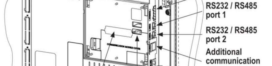

11 Connec ons 6 California Motor Controls, Inc. Benicia, CA
12 Communica on Ports The PUMP Vision PV1200 has two serial ports. Both can be set for RS232 or RS485 independently. The PUMP Vision is connected directly to the PC with a standard RJ11 type cable which should not be longer than 10 when using RS232. An RJ11 to 9 pin D connector is used to connect to the PC. RS232/RS485: DIP Switch Settings The settings below are for each Switch Settings RS232* ON ON ON OFF ON OFF RS485 OFF OFF OFF ON OFF ON RS485 with termination** ON ON OFF ON OFF ON *Default factory setting **Causes the unit to function as an 7 end unit in an California Motor Controls, Inc. Benicia, CA RS485 network
13 Communica on Ports RS485 Use RS485 to create mul drop network containing up to 32 sta ons, or for Modbus communica ons. Note that when a port is set to RS485, both RS232 and RS485 can be used simultaneously if flow control signals DTR and DSR are not used. Note that the ports are not isolated. If the controller is used with a non isolated external device, avoid poten al voltage that exceeds ±10V. To avoid damaging the system, all non isolated device ports should relate to the same ground signal. Use shielded, twisted pair cable. Minimize the drop length leading form each device to the bus. Ideally, the main cable should be run in and out of the network device. Do not cross posi ve (A) and nega ve (B) signals. Posi ve terminals must be wired to posi ve and nega ve terminals to nega ve. 8 California Motor Controls, Inc. Benicia, CA
14 Wiring Wiring Considera ons. A technician or engineer trained in the local and Na onal Electric Code should perform all tasks associated with the electrical wiring of the controller. Input or output cables should not be run though the same mul core cable or share the same wire. Do not lay input or output cables near high voltage power cables. Allow for voltage drop and noise interference with input and output lines used over an extended distance. Use wire that is properly sized for the current load. Double check all the wiring before turning on the power supply. Unused I/O terminals should not be connected. Ignoring this direc ve may damage the controller. On board I/O I/O connec on points are provided by external connectors at the top and bo om of the controller. The connectors plug in, enabling quick and easy removal. They provide screw type connec on points for the power source, inputs an outputs. The connec on points are clearly labeled on the controller itself. The top generally provides connec ons for the power supply, analog inputs and digital inputs. The bo om connector provides terminals for the relay outputs. Connec ons to the Controller 1.Strip the wire to a length of inches. 2.Unscrew the terminal to its widest posi on before inser ng a wire. 3.Insert the wire completely into the terminal to ensure a proper connec on. 4.Tighten enough to keep the wire from pulling free. 5.Use 14 gauge to 26 gauge wire. 6.Do not exceed 1 inch pounds of torque. 7.We recommend crimp connectors (ferrules) on the wire ends. 9 California Motor Controls, Inc. Benicia, CA
15 Typical Wiring Diagram for Constant Speed or VFD Mode Wiring Diagram 10 California Motor Controls, Inc. Benicia, CA
16 Connect input and output devices as needed. Digital Inputs I0 Hi speed input for pulse type flow meter I1 Suc on pressure switch I2 System enable I3 Pump 1 HOA AUTO I4 Pump 2 HOA AUTO I5 Pump 3 HOA AUTO I6 Pump 4 HOA AUTO I7 Pump 1 Run Input I8 Pump 2 Run Input I9 Pump 3 Run Input I10 Pump 4 Run Input I11 VFD 1 fault input I12 VFD 2 fault input I13 VFD 3 fault input I14 VFD 4 fault input I15 NA I16 Flow switch I17 NA Op onal I32 Generator running I33 Generator fault I34 Power failure I35 UPS failure I36 Dry well water I37 Intrusion I38 Op on alarm 1 I39 Op on alarm 2 I40 NA I41 NA I42 NA I43 NA I44 NA I45 Op on alarm 3 I46 Op on alarm 4 I47 Op on alarm 5 I/O List Analog AN0 AN1 AN2 AN3 4 20mA Suc on transducer 4 20mA Discharge transducer PT100 (alpha=0.0385) temperature sensor 4 20mA Flow Meter 11 California Motor Controls, Inc. Benicia, CA
17 Digital Outputs I/O List O0 O1 O2 O3 O4 O5 O6 O7 O8 O9 O10 O11 O12 O13 O14 O15 O16 General Alarm Indicator NA Pump 1 Run Pump 2 Run Pump 3 Run Pump 4 Run Pump 1 out of service Pump 2 out of service Pump 3 out of service Pump 4 out of service Horn High system pressure Low system pressure High suc on pressure Low suc on pressure NA General Alarm Contact Analog Outputs AOUT0 4 20mA VFD 1 speed reference AOUT1 4 20mA VFD 2 speed reference AOUT2 4 20mA VFD 3 speed reference AOUT3 4 20mA VFD 4 speed reference (these are used only if VFDs are not connected by network to the PV600) 12 California Motor Controls, Inc. Benicia, CA
18 SEQUENCE OF OPERATION Pump Staging When the PV1200 has been fully configured, all of the level control set points have been entered and all alarm condi ons are sa sfied, the system is ready to operate. The PV1200 has a dashboard for each pump that provides a HAND OFF AUTO selector switch for control of the pump. When in the HAND posi on, the PV1200 will command the pump to run as long as there are no alarm condi ons that are configured for pump shutdown on fault. In the AUTO posi on, the pumps will run when called by the pump sequencer. The PV1200 can be configured to run pumps in a number ways since the pump sequencer has two parts; the pump stager and the alternator. The pump stager calls for the pumps as needed based on pressure, VFD speed, or flow condi ons. The alternator determines which pump will run when the stager calls. PUMP STAGING Variable Speed Pumps Lead Pump Start When the system pressure falls below the pump start set point, or when the BMS call signal is given, the lead pump start delay mer will begin ming. Once the mer elapses, the lead pump will start. The speed of the VFDs will be automa cally modulated by the PUMP Vision to maintain the target pressure set point. When the lead pump starts, the VFD will immediately ramp up to the minimum run set point at the rate programmed into the VFD accelera on func on. When the VFD has reached the minimum speed set point, the sample cycle mer begins ming. When the sample cycle mer elapses, a change will be made to the VFD speed propor onal to the system pressure devia on from the target pressure set point. The speed can increase up to the maximum speed set point and decrease to the minimum speed set point. Lead Pump Stop The PV1200 can be configured to stop the lead pump by BMS control or automa cally by flow and/or pressure. The pumps can also be configured to shut down due to maximum run me and alarm condi ons. In a normal pressure booster system, it is important to stop the pumps when there is a no flow condi on to prevent overhea ng the pumps due to lack of water movement. The PV1200 can determine a no flow condi on by flow switch, flow meter, or with a sensorless no flow monitor. It is also important to prevent the pumps from short cycling (star ng too frequently), so a minimum run mer keeps the lead pump running for a preset minimum amount of me. Once the minimum run mer has elapsed, pressure is sa sfied, and the no flow condi on is met, the lead pump will shut down. Lag Pump Staging The PV1200 can be configured to call for lag pumps based on VFD speed, pressure, or flow (when a flow meter is installed). In addi on, it is possible to combine the VFD speed or the flow modes with the pressure mode so that both speed and pressure, or flow and pressure, be sa sfied to stage the pump. The pressure only mode is not available on VFD systems. VFD Speed Start When the VFD speed reference signal to the running pump(s) rises above a start lag pump set point, the PV1200 will call for another pump to start a er a pump start delay me. The start set point is typically set at a point on the end of the pump curve where the running pump(s) has reached its maximum flow capacity. 13 California Motor Controls, Inc. Benicia, CA
19 SEQUENCE OF OPERATION Pump Staging VFD Speed Stop When the VFD speed reference signal to the running pump(s) drops below a stop lag pump set point, the PV1200 will being a lag pump stop delay mer. When the mer expires, the lag pump is stopped. The lag pump stop delay mer is used to prevent short cycling of the lag pumps. The stop set point is typically set at a point on the low end of the pump curve where the running pump(s) has reached its minimum flow capacity. Flow Staging Flow staging mode is only available when a flow meter is wired in to the PV1200 and replaces the VFD Speed staging mode. When flow staging mode is selected, the lag pumps are started and stopped based on user preset flow rates that are typically determined by coordina on of the pump curves, system piping, usage condi ons, and other system factors. When flow rises above a start lag pump set point, and the lag pump start delay mer expires, a lag pump is called. When the flow rate drops below a stop lag pump set point, the PV1200 will being a lag pump stop delay mer. When the mer expires, the lag pump is stopped. The lag pump stop delay mer is used to prevent short cycling of the lag pumps. VFD Speed/Pressure Staging When VFD Speed and the Pressure staging modes are selected together, the PV1200 stages the pumps in the same manner as VFD speed mode, but also requires that the discharge pressure is above the lag pump stop pressure set point to stop the lag pump, or below the lag pump start pressure set point to start the lag pump. Flow/Pressure Staging When Flow and the Pressure staging modes are selected together, the PV1200 stages the pumps in the same manner as Flow mode, but also requires that the discharge pressure is above the lag pump stop pressure set point to stop the lag pump, or below the lag pump start pressure set point to start the lag pump. PUMP STAGING Constant Speed Pumps Lead Pump Start When the system pressure falls below the pump start set point, or when the BMS call signal is given, the lead pump start delay mer will begin ming. Once the mer elapses, the lead pump will start. Lead Pump Stop The PV1200 can be configured to stop the lead pump by BMS control or automa cally by flow and/or pressure. The pumps can also be configured to shut down due to maximum run me and alarm condi ons. In a normal pressure booster system, it is important to stop the pumps when there is a no flow condi on to prevent overhea ng the pumps due to lack of water movement. The PV1200 can determine a no flow condi on by flow switch or a flow meter. It is also important to prevent the pumps from short cycling (star ng too frequently), so a minimum run mer keeps the lead pump running for a preset minimum amount of me. Once the minimum run mer has elapsed, pressure is sa sfied, and the no flow condi on is met, the lead pump will shut down. Lag Pump Staging The PV1200 can be configured to call for lag pumps based on pressure or flow (when a flow meter is installed). In addi on, it is possible to combine flow mode with the pressure mode so that both speed and pressure, or flow and pressure, be sa sfied to stage the pump 14 California Motor Controls, Inc. Benicia, CA
20 SEQUENCE OF OPERATION Pump Staging Pressure Staging When pressure rises above a start lag pump set point, and the lag pump start delay mer expires, a lag pump is called. When the pressure drops below a stop lag pump set point, the PV1200 will being a lag pump stop delay mer. When the mer expires, the lag pump is stopped. The lag pump stop delay mer is used to prevent short cycling of the lag pumps. Flow Staging Flow staging mode is only available when a flow meter is wired in to the PV1200. When flow staging mode is selected, the lag pumps are started and stopped based on user preset flow rates that are typically determined by coordina on of the pump curves, system piping, usage condi ons, and other system factors. When flow rises above a start lag pump set point, and the lag pump start delay mer expires, a lag pump is called. When the flow rate drops below a stop lag pump set point, the PV1200 will being a lag pump stop delay mer. When the mer expires, the lag pump is stopped. The lag pump stop delay mer is used to prevent short cycling of the lag pumps. Flow/Pressure Staging When Flow and the Pressure staging modes are selected together, the PV1200 stages the pumps in the same manner as Flow mode, but also requires that the discharge pressure is above the lag pump stop pressure set point to stop the lag pump, or below the lag pump start pressure set point to start the lag pump. 15 California Motor Controls, Inc. Benicia, CA
21 SEQUENCE OF OPERATION Alterna on Jockey Alterna on In Jockey Alterna on mode, Pump 1 is always the first pump to run. The remaining lag pumps are alternated as if they were in a full alterna on sequence. For example, in a triplex jockey alterna on system where the first lag called in this cycle is Pump 2, the next pumping cycle will call Pump 3 as the first lag. Jockey Alterna on is only available for triplex and quadruplex systems. Full Alterna on Each me a pumping cycle starts a er the system has been at rest, the next pump in sequence will be the lead pump. So if pump 1 is lead pump in this cycle, Pump 2 will be lead pump in the next cycle. The other pump(s) in the system will start as lag pump(s) as needed. Constant Lead In Constant Lead mode, a certain pump is selected to always be the lead pump. Slave Mode The PV1200 can be configured to run any individual lag pump as a slave to the lead pump. When a lag pump is set to Slave mode, it will run in unison with the lead pump. Standby Mode. The PV1200 can be configured to run any individual lag pump as a standby pump to the system. The standby pump only runs if another called pump has failed. This is used when there are more pumps in the system than there is capacity to handle the flow, and the extra pump(s) are in the system for redundancy. 16 California Motor Controls, Inc. Benicia, CA
22 SEQUENCE OF OPERATION Alarms Alarm Condi ons All alarm condi ons with operate according to the way they are set up. Each alarm can op onally be set up to: Be enabled or disabled Stop the pumps Require manual reset Sound the horn Light the alarm light Flash the alarm light Close the alarm contact Send an User adjustable me delay All enabled alarm condi ons will be logged into the alarm data logger. All enabled alarm condi ons will be managed by the fault handler. For all alarm condi ons, touching the screen of the PV1200 will silence the horn output. Inputs are provided for the following alarm condi ons: High Discharge Pressure Low Discharge Pressure Transducer Failure Pump Failure MOTOR Vision Fault VFD Failure High Suc on Pressure Low Suc on Pressure High Temperature Moisture in Motor In VFD mode the VFD Fault condi ons are monitored through Modbus and annunciated on the controller. Pump Failure This condi on is determined by the motor starter failing to close an input to the controller within a preset me period. If a pump fails to start, the pumping duty is automa cally transfer to the next available pump in sequence. The pump can be taken Out of Service and this failure alarm is prevented, by pu ng either the so HOA, or the panel HOA into the OFF posi on. This allows maintenance of the pump without genera ng an alarm condi on. As with a pump failure condi on, the pumping duty is automa cally transferred to the remaining pump(s). 17 California Motor Controls, Inc. Benicia, CA
23 SEQUENCE OF OPERATION Logs and Trend Graphs Fault Data Logging Fault condi ons are logged into memory with a date and me stamp. When a fault condi on occurs, the fault status indicator will light on the main screen and the Alarm Log will display any ac ve faults. Touching the fault status indicator will take the user to the Alarm Handler, where alarm condi ons can be viewed and managed. The Alarm Log will display any ac ve alarms. Touching the Alarm Log bu on will allow the user to scroll through any ac ve alarms if more than one are present. Holding the Alarm Log will take the user to the System Alarm Log, where details including the me date, me of occurrence and alarm condi on can be viewed and managed. The screen can be scrolled down through the past 1000 fault condi ons. When the screen is exited and then reentered, the log automa cally returns to showing the latest fault condi ons. Trending The on screen trending graph plots the sump or tank level with a reading saved every second. It saves history for the past 1.5 hours. The graph can be scrolled by the user to view the history. The op onal micro SD card records the trend data in a file that is automa cally created once a month. A maximum of 63 months is retained on the SD card. 18 California Motor Controls, Inc. Benicia, CA
24 MAIN DASHBOARD Status Bar Alarm Bar Pump Status Overview Suc on Discharge Menu Bar Overview For each applica on type, the PUMP Vision PV1200 has a Main Dashboard that provides a complete overview of the system status and touch access to pump dashboards, logs, trends, set points, and complete system configura on. Main Dashboard Screen Elements and Func ons Status Bar Depending on the current display, the top of the screen status bar may display the name of the current display screen, system pressure, ba ery status, level, date and me. A Status Bar is on every display screen in the PV1200 controller. All Status Bars include the display name, and most include the pressure display. Menu Bar Depending on what screen you are on, different menu op ons appear. The Main Dashboard s Menu Bar includes bu ons to access the Pump Dashboards and the Setup display. Alarm Bar The Main Dashboard s Alarm Bar includes two alarm message bars, Alarm Handler bu on, Alarm Silence, Alarm Test, and Alarm Reset bu ons. Pump Status Overview An overview is provided for each pump configured in the system. Pump status, HOA, run data, and access to Pump Dashboards and MOTOR Vision data is available. Suc on Depending on the configura on of the system, the suc on pressure or level is displayed, as well as the high and low pressure or level alarm set points. If the suc on source is from a tank, a fill solenoid can be enabled and set points displayed. Discharge The system discharge pressure is displayed here, along with the high and low pressure alarms set points. 19 California Motor Controls, Inc. Benicia, CA
. Ba ery Status This bu on will give instruc ons on how to change the ba ery.")
25 Display Name Pressure Booster MAIN DASHBOARD Status Bar System Time System Date Ba ery Status A blue status bar is at the top of each screen in the PV1200. The status bar includes: Display Name MAIN DASHBOARD Touch for program informa on (only on the Main Dashboard). Ba ery Status This bu on will give instruc ons on how to change the ba ery. It will change color to yellow and display a warning message when the ba ery is low. The PV1200 uses a 3V Lithium CR2450N coin type ba ery that is located behind a user accessible cover in the back of the unit. The lithium ba ery will last for up to 10 years in the PV1200 if the unit is kept powered up. The ba ery is used to maintain the current me, and to retain the system configura on and user set points that are stored in RAM memory. Note: the configura on and user set points are also stored in non vola le Flash RAM memory if the system has been backup up, but the PV1200 will need user interven on to restore the system if the power fails while the ba ery is dead. System Time Displays the current system me. Touch the bu on to set Time and Date of the PV1200. The system me is used to provide a date and me stamp to system events, data logging, and trending. Keeping the me accurate will assist in providing useful diagnos c informa on. When the PV1200 is connected to the Internet, it can keep the date and me current automa cally with periodic connec on to an NIST Time Server. System Date Displays the current date. The date is changed in the System Time setup screen. Pressure The pressure is shown on nearly all screens except the Main Dashboard on the right side of the Status Bar. 20 California Motor Controls, Inc. Benicia, CA

26 MAIN DASHBOARD Alarm Bar Main Alarm Message Bar Op on Alarm Message Bar Alarm Test/ Alarm Silence Reset Alarm Handler Bu on Main Alarm Message Bar If there are active alarms, this message bar displays the alarm condition. If there are no alarms, SYSTEM NORMAL is displayed. Touching the message text will scroll through all of the active alarm conditions if more than one condition is active. The main message bar shows the 10 possible level control alarms. Option Alarm Message Bar If there are active option alarms, this message bar displays the alarm condition. If there are no alarms, the bar is blank. Touching the message text will scroll through all of the active alarm conditions if more than one condition is active. The option message bar shows the 10 possible option alarms. Reset This button only appears when there is a fault condition that can be manually reset. Touching the button will reset the alarm if the condition has cleared. Number of Active Alarms If there are active alarms, this button displays red and indicates the number of active alarm conditions. Touch the button for the Alarm Handler. The button does not appear if there are no unacknowledged alarms. Alarm Test/Alarm Silence Touch the button for the Alarm Test screen. This button will read SILENCE when the horn is sounding as it doubles as the alarm silence button. 21 California Motor Controls, Inc. Benicia, CA
27 MAIN DASHBOARD Elements Pump Staging Set Points VFD Speed Reference Alterna on Status Menu Menu The menu bar at the bo om of the Main Dashboard screen provides access to: SET POINT SETUP Access to Level 1 password screen and then staging control set point edi ng. TIMERS Access to the Timer Menu. ALTERNATION Access to the Alterna on Setup screen. LOGS Access to the Alarm Log. From the Alarm Log, access to the Run Log and Flow Logs. TRENDS Access to the Main Trend screen, From the Main Trend, access to the Trend History and Flow Trends. CONFIGURATION Access to all levels of controller configura on VFD Speed Reference Displays the speed command to the VFDs in percentage of maximum speed. Not displayed when the system is not configured for VFDs. Alternation Status The pump alternation sequence mode and the current lead pump status is displayed here. For more information on the modes and setup of the alternator, refer the Alternator page of this manual. Pump Staging Set Points The user entered set points for starting and stopping the pumps are shown here and can be modified by touching the SET POINT SETUP button and entering the Level 1 password. 22 California Motor Controls, Inc. Benicia, CA
28 MAIN DASHBOARD Elements Pumps Called Pumps Running No flow Shutdown Pumps Called As the level rises (or drops in tank fill applications) the pump start set points are tripped and pumps are called to run. This field indicates either: SYSTEM IS IDLE (X number) PUMPS RUNNING TIME CLOCK SHUTDOWN The color of the text changes from green for idle, amber for one pump called, and red for more than one pump called. Pumps Running This field responds back with the number of pumps running and is blank when no pumps are running. No flow Shutdown This field indicates the status of the sensorless no flow shutdown monitor. The NFS system determines that the flow has stopped by testing for a drop in pressure after a drop in VFD speed. The indicator has the following possibilities: Blank NFS system is not active either due to constant speed system, when the pumps are not running, or the speed of the VFDs is changing, indicating a change in flow rate. NFS ACTIVE Appears after the lag pumps have stopped and the lead pump minimum run timer has expired and remains until NFS testing begins. NFS TESTING Appears when there has been no change in VFD speed outside of a 3% dead band for the amount of time on the NFS Idle Timer. NFS is not available on constant speed pressure booster systems. 23 California Motor Controls, Inc. Benicia, CA


29 MAIN DASHBOARD Elements Flow Water Temperature Pump Mini Dashboards Pump Dashboard Water Temperature Displays the water temperature and alarm set point if the system is configured with a temperature sensor. Flow Flow rate and total are displayed here on systems with a flow meter wired to them. Flow data and total data logging can be enabled. Pump Mini Dashboard A mini dashboard is provided for each pump configured in the system. The features and functions shown above for Pump 2 are the minimum provided. In VFD or MOTOR Vision systems, pump running current and frequency may be shown. The status of each pump is shown with a graphic image of a pump in color, and with text on a namplate. The color key for the pump status: GRAY OFF = Pump stopped GREEN RUNNING = Pump running RED FAILED = Pump failed BLUE OUT OF SERVICE = Pump Out of service LIGHT BLUE NEEDS MAINT. = Pump needs maintenance YELLOW CALLED = Pump called, but not yet running ORANGE = REMOTE RUN = Remote run command (external to the PUMP Vision). 24 California Motor Controls, Inc. Benicia, CA


30 MAIN DASHBOARD SET POINT SETUP Password Entry Set Point Entry Set Point Setup Overview The Main Dashboard displays the set points for most of the system opera onal set points including suc on pressure, system pressure, and temperature alarms, suc on water tank fill, lead start, target pressure, and lag start/ stop set points. The set points can be changed by touching the SET POINT SETUP bu on on the menu bar. The user is taken to a Level 1 password entry screen. A er the password is successfully entered, the desired set point can be altered by touching the entry values, which are blue when in the edit mode, and entering a new value through the numeric keypad. Set Point Setup This bu on takes the user to password entry screen. Password Entry Enter the Level 1 password. See the Password Setup page of this manual for more informa on on the password. Set Point Entry Once the Level 1 password has been correctly entered, the set points on the Main Dashboard turn blue which indicates that they can be edited. Touch the set point to be edited and the numeric entry keypad appears. Enter the new set point. NOTE: In staging mode configura ons other than VFD Speed, the set points for pump staging are not accessible from the Main Dashboard. Set points for pressure and flow staging can only be entered through the Start, Stop, & Target Set Point screen. Touching the SET POINT SETUP bu on on the menu bar, then entering the correct level 1 password, accesses this screen directly from the Main Dashboard. Once the Start, Stop, & Target Set Point screen is exited, the alarm set points that are on the Main Dashboard are in the edit mode and can be adjusted too. 25 California Motor Controls, Inc. Benicia, CA


31 PUMP DASHBOARDS Common Pump Status Nameplate Pump Status Indicator Overview Pump Dashboards A dashboard is provided for each pump that is configured in the system and is each is op mized for FVNR, VFD or MOTOR Vision systems. Just as the Main Dashboard provides an overview of the en re pump sta on, the Pump Dashboards provide an overview of the opera on and status of the individual pumps. Pump Status Nameplate Displays the current status of the pump. Status messages include: OFF, CALL, RUNNING, OUT OF SERVICE, FAILED, REMOTE RUN, and MAINT. DUE. The PUMP Vision has an input for an auxiliary contact of the motor starter to wire to. It monitors the status of either that input, or the run status of a MOTOR Vision starter or VFD connected by Modbus to determine if the pump is running or stopped. When the PUMP Vision output energizes the motor starter, the status is CALLED. When the input goes high, the status is RUNNING. If the run read back does not go high, the status is FAILED. The status is OUT OF SERVICE if the input from the hardware HOA is not high. Pump Status Indicator Light Status of each pump is shown in color. The color key for the pump status: Light Green: Pump running shows motor Hz in VFD mode Dark Green: Pump stopped Red: Pump failure flashing for maintenance due Blue: Pump out of service Yellow: Pump called, but not yet running Light Blue (flashing): Maintenance due Amber: Pump running by remote hardwired signal The key above shows the default Pump Status Bu on colors. The colors can be remapped by the user to other color themes in the PV1200 Op on Configura on screen in the Level 3 configura on mode. 26 California Motor Controls, Inc. Benicia, CA

32 PUMP DASHBOARDS Common Run Stats Alarm Indicators Run Stats Run Timer Elapsed Time Meter Displays the Current (or previous, if idle) run dura on. Displays the total run me of the pump. The display is in hundredths of an hour and will display over 40 million hours. These can be reset in the ETM & Counter Reset screen in the Diagnos cs Menu. Start Counter Displays the total number of pump starts. This counter can count to over 32,000 starts. These can be reset in the ETM & Counter Reset screen in the Diagnos cs Menu. Alarm Indicators Status indicators monitor the pump condi ons for any alarm that the pump is configured for. System Problem Pump Starter Failure VFD/MV/RVSS Fault High Motor Temp Moisture In Motor Shows Orange indicator when any abnormal condi on exists in the system. It is shown on the Pump Dashboard page to alert the user that a system problem exists that may be preven ng the pump from running. A watchdog mer monitors the pump starter and requires a signal feedback prior to the mer elapsing to prove the starter has responded to a call request. A fault in the VFD or in VFD communica on. This alarm is replaced with a MO TOR Vision Fault alarm in MOTOR Vision systems, and RVSS Fault alarm in RVSS systems. Indicates a high motor temperature condi on wired to a hardware input. Indicates a seal failure condi on wired to a hardware input. 27 California Motor Controls, Inc. Benicia, CA

33 PUMP DASHBOARDS VFD Systems Manual Speed Se ng Increment & Decrement So HOA Bu ons So HOA Switch Starter Status VFD/RVSS Fault Log/ MVision Dashboard So HOA Bu ons Touch these bu ons to change the status of the so HOA switch. The so HOA is in the PUMP Vision to allow remote control of the pumps when the controller is wired through a network or wireless connec on. HAND OFF Se ng the switch to hand runs the pump as long as there are no shutdown condi ons. Se ng the switch to off puts the pump into the out of service condi on. So HOA Switch A virtual three posi on switch allows the user to see whether the so HOA is set to HAND, OFF, or AUTO. The switch is only opera onal when the HOA AUTO input of the PV1200 is high. When the HOA AUTO input is off, the switch image turns BLUE* to indicate that the pumps hardwired HOA is in the OFF posi on the pump is out of service. In the event that the HOA AUTO input is off and the RUN input is high, the PV1200 assumes that the pump starter is ge ng a remote run command and the switch image turns ORANGE*. *The colors that the so HOA switch turn are the default Pump Status Bu on colors. The colors can be remapped by the user to other color themes in the PV1200 Op on Configura on screen in the Level 3 configura on mode. Manual Speed Se ng Displays the current VFD speed in terms of percentage. The speed can also be directly adjusted by touching the manual speed display and then entering the desired set point on the keypad screen. Increment This bu on gradually increases the VFD manual speed. Decrement This bu on gradually decreases the VFD manual speed. Note: Touching an Increment/Decrement bu on changes the value by 0.1%. Touch and hold to auto increment the set point. Starter Status In VFD or MOTOR Vision configured systems, the status of the Modbus communica on to the starter is monitored and displayed here. VFD/RVSS Fault Log/MOTOR Vision Dashboard In VFD, RVSS, or MOTOR Vision configured systems, this bu on gives access to either the VFD or RVSS Fault Log in VFD or RVSS systems, or the MOTOR Vision Dashboard in MO TOR Vision configured systems. 28 California Motor Controls, Inc. Benicia, CA
34 PUMP DASHBOARDS VFD Systems VFD Gauges Fault Status VFD Gauges Analog gauges with digital readings below show important motor informa on. Some gauges are not visible when the VFD that is connected does not support the func on. Kilowa s VFD Speed Command VFD Output Frequency Motor Current The gauge displays the kilowa s being consumed and the digital display shows the total kwh (mwh) hours consumed (if available from starter or VFD). Displays the current VFD Speed Reference sent from the PV1200 in percentage (0 100%). Displays the current VFD output frequency in hertz (0 60 Hz). Displays the motor current draw in Amps. VFD Fault Status Displays the current VFD status or fault. Touch the bu on to go to the VFD fault log. The VFD Fault Log displays the last 250 VFD fault condi ons. This feature is currently only available on the Schneider, A B, and ABB drives. 29 California Motor Controls, Inc. Benicia, CA
35 PUMP DASHBOARDS MOTOR Vision Systems Gauges MV Status MOTOR Vision Dashboard Overview The PV1200 con be connected to the Insight smart motor overload relay from Eaton Corpora on, or the Tesys U Line smart motor starter from Schneider Electric. These overload relays connect to the PV1200 by Modbus and provide much informa on about the opera ng condi ons of the motor. In addi on to the features common to all Pump Dashboards, the MOTOR Vision dashboard includes: MV Status The MOTOR Vision status indicator confirms that the MOTOR Vision starter is connected and will indicate WARNING or TRIPPED if there is a MOTOR Vision fault. MOTOR Vision Dashboard Touch the message here to access the MOTOR Vision Dashboard. MOTOR Vision Insight Gauges Kilowa s Voltage Frequency Motor Current U Line Gauges Thermal Load Motor Current The gauge displays the kilowa s being consumed Displays the supply average voltage. Displays the supply frequency in hertz (0 60 Hz). Displays the motor current draw in Amps. Displays the motor thermal load as a percentage of the overload set point. Displays the motor current draw in Amps. 30 California Motor Controls, Inc. Benicia, CA
 Main Trend Graph The main trend graph has three possible pens.")
36 MAIN TREND SCREEN Graph Scale Change Pen Focus Grid Lines Return Historical Trend The trend screen charts the system pressure, suc on level or pressure, and VFD speed (or number of pumps running in non VFD systems.) Main Trend Graph The main trend graph has three possible pens. Red pen = main sensor Yellow pen = VFD % speed, or number of pumps running in non VFD systems Green pen = suc on level or pressure Change Pen Focus To change the focus of the graph so that the scale of a different pen is shown, touch the graph to toggle through the choices. Graph Scale Each pen has its own scale. The scale for each pump is user adjustable by touching the scale s max. Number and entering a new value. Mode Selec on Touch this bu on to toggle between Run and History mode. Run the graph shows current me for the past minute (approximately). History the graph can be scrolled using the forward and backward bu ons. Grid Lines Touch the G bu on to add graph lines to the display. Touch again to hide the lines. Flow Touch this bu on to access the flow trend chart when flow monitoring and logging are enabled. Historical Trend Touch this bu on to access the historical trend chart when SD Card data logging is enabled. The bu on does not appear if there is no SD Card installed. 31 California Motor Controls, Inc. Benicia, CA
37 HISTORICAL TREND SCREEN SD Memory Card Chart Name Grids Lines Displayed File When an SD card is install in the PV1200 and Trending is enabled in the SD Memory Card Data Logging setup screen, the main trend chart is recorded onto the SD Card. The PV1200 automa cally creates a new trend data file each month. A maximum of 63 months of data can be stored on one card before files must be deleted or a new card installed. Within each data file are segments. At least one segment exists in each file and a new segment is created within the month s file each me the PV1200 is power cycled. Tip: To maintain single segment charts within each file, install a UPS to the PV1200 power supply to prevent power cycling the controller. The files can be displayed on the PV1200 screen, or they can be downloaded or copied from the SD card to a PC and reviewed using the SD Card Manager so ware. When the screen above is accessed from the Main Trend screen, the most current month s data file is ini ally displayed. Depending on the length of the first segment, it may take some me (up to a couple of minutes) to load the data for display. Once the data is displayed it can be scrolled though to review trends. If mul ple segments exist within the month s data file, they can each be viewed by scrolling through the segments. The historical trend graph has three possible pens. Red pen = main sensor Yellow pen = VFD % speed, or number of pumps running in non VFD systems Green pen = suc on level or pressure Chart Name Displayed File Displays the month and year of the chart being displayed. Grid Lines Touch the G bu on to add graph lines to the display. Touch again to hide the lines. 32 California Motor Controls, Inc. Benicia, CA


38 HISTORICAL TREND SCREEN SD Memory Card File Name Scroll Bar File Status Segment No. Back Forward Most Recent Seg. Back Seg. Forward File Name This is the name of the file as stored on the SD memory card. Scroll Bar The scroll bar controls where in the graph segment is being displayed. The graph can be scrolled by the page by touching the arrow bu on at either end, or dragging the handle and sliding it to a point elsewhere in the chart. Segment No. Shows the segment number currently being displayed. Back Touch this bu on to view to the previous month s file. If no file exists for the month being request, FILES DOES NOT EXIST IS DISPLAYED. Forward Touch this bu on to view to the following month s file. If no file exists for the month being request, FILES DOES NOT EXIST IS DISPLAYED. Most Recent Touch this bu on to advance to the most recently month s file. Seg. Back Touch this bu on to return to the previous segment in the month. Seg. Forward Touch this bu on to advance to the next segment in the month. Each segment must load in turn and each may take some seconds to load. File Status Shows LOADING when a data file segment is in the process of being read to the screen and END OF FILE when the last segment in the file is being displayed. 33 California Motor Controls, Inc. Benicia, CA


39 ALARM LOG Ac ve Faults Last Entry Page Up Line Up Line Down Page Down Clear Log Return Run Log Flow Log Overview By touching the Alarm Log label on the main screen, the user can access the Alarm Log screen, that displays the alarm condi ons with date and me of occurrence. This log saves the past 1,000 alarm condi ons. Last Entry Touch this bu on to return to the most recent alarms a er scrolling. Page Up Touch this bu on to move up a page in the alarm history. Line Up Touch this bu on to scroll up one line in the alarm history. Line Down Touch this bu on to scroll down one line in the alarm history. Page Down Touch this bu on to move down a page in the alarm history. Return Touch this bu on to return to the Main Screen. Clear Log Touch this bu on to clear the Alarm Log. A password screen will pop up that requires the entry of the clear log password, Ac ve Faults The Number of ac ve faults is displayed here. Touch this bu on to access the Alarm Handler. Run Log Touch this bu on to access the pump run me log. Flow Log Touch this bu on to access the flow logs (if flow monitoring and logging is enabled). 34 California Motor Controls, Inc. Benicia, CA

40 RUN LOG Last Entry Page Up Line Up Line Down Page Down Clear Log Return Alarm Log Flow Log Overview The Pump Run Log records the past 500 pump run events. It is accessed from the Pump Control screen. The Pump Called, Date, Start/End mes and Dura on are stored each me a pump is run. Last Entry Touch this bu on to return to the most Run history a er scrolling. Page Up Touch this bu on to move up a page in the run history. Line Up Touch this bu on to scroll up one line in the run history. Line Down Touch this bu on to scroll down one line in the run history. Page Down Touch this bu on to move down a page in the run history. Return Touch this bu on to return to the previous screen. Clear Log Touch this bu on to clear the Run log. A password screen will pop up that requires the entry of the clear log password, Run Log Touch this bu on to access the pump run me log. Flow Log Touch this bu on to access the flow logs (if flow monitoring and logging is enabled). 35 California Motor Controls, Inc. Benicia, CA
. The VFD logs save the last 250 fault condi ons. Last Entry Touch this bu on to return to the most recent fault a er scrolling.")
41 VFD FAULT LOG Last Entry Page Up Line Up Line Down Page Down Clear Log Return Overview There is a separate fault log for each of the VFDs, accessed from the Pump Control screen when the system is in the VFD mode (when communica ng with the PV1200 through Modbus). The VFD logs save the last 250 fault condi ons. Last Entry Touch this bu on to return to the most recent fault a er scrolling. Page Up Touch this bu on to move up a page in the fault history. Line Up Touch this bu on to scroll up one line in the fault history. Line Down Touch this bu on to scroll down one line in the fault history. Page Down Touch this bu on to move down a page in the fault history. Return Touch this bu on to return to the Pump Screen. Clear Log Touch this bu on to clear the fault log. A password screen will pop up that requires the entry of the clear log password, California Motor Controls, Inc. Benicia, CA

42 ALARM HANDLER Message Bar Alarm Handler Overview In the event of an alarm condi on, at least two indica ons will appear on the main screen. Alarm Message Bar The alarm message bar will display the alarm that has occurred. In the event of mul ple alarms being triggered, the latest alarm will be displayed. Touching the alarm message bar will scroll through the alarm messages. Alarm Handler The Alarm Handler will appear showing the number of ac ve alarms. Touching the Alarm Handler bu on will take the user to the Alarm Handler screen. Once the alarms are no longer ac ve, the Alarm Handler will display FAULTS NEED ACK (acknowledgment). Once the user has acknowledged the alarms the Alarm Handler will disappear. 37 California Motor Controls, Inc. Benicia, CA

43 ALARM HANDLER Return Reset Details Group Count Overview The Alarm Handler is a series of screens that provides access to ac ve and non acknowledged alarm condi ons. The handler displays informa on about each alarm condi on. This is the first screen that appears when entering the Alarm Handler. It displays the number of alarms that have occurred within the two alarm groups (System Alarms and Op on Alarms). Return Touch this bu on to return to the previous screen. Reset Touch this bu on to acknowledge and clear all non ac ve alarms within the alarm group. Note: Once the reset bu on has been touched, details regarding the alarm condi on are erased from the Alarm Handler. The alarm record will s ll exist in the alarm log and data logs. Details Touch the Details bu on for the group to be viewed. This accesses the next screen in the Alarm Handler that shows which alarms have occurred within the group. Group Count Indicates the number of alarms that have occurred within each alarm group. 38 California Motor Controls, Inc. Benicia, CA

44 ALARM HANDLER Return Alarm Name Details Date & Time Acknowledged Alarm Ac ve Refresh Overview The second level of the Alarm Handler is list of all alarm condi ons that are either s ll ac ve, or are inac ve but have not been acknowledged by the operator. Once an alarm is no longer ac ve and it has been acknowledged, it is removed from the list. Date & Time This shows the date and me the alarm condi on occurred. Details Magnifying Glass Touch this to go to the next level screen. Each alarm condi on has one of these bu ons to give access to the specific informa on on the alarm status and condi on. Acknowledged This shows whether or not the alarm has been acknowledged in the Alarm Details screen. Alarm Name This shows the alarm condi on. Refresh Touch this bu on to refresh the list. Refresh Touch this bu on to clear all inac ve alarms from the list. Return Touch this bu on to return to the previous screen. 39 California Motor Controls, Inc. Benicia, CA


45 ALARM HANDLER Return to Previous Name Date & Time Count Status Acknowledge Overview Scroll Bu ons The third level of the Alarm Handler is detailed informa on about the specific alarm condi on. Alarm Name This shows what the alarm condi on is. Alarm Time and Date This shows the latest me the alarm condi on occurred. Count This shows how many mes the alarm condi on has occurred. Status This shows if the alarm is ac ve or not. Acknowledge Touch the Ack bu on to acknowledge this alarm. Scroll Touch the scroll bu ons to scroll through the other uncleared alarms. 40 California Motor Controls, Inc. Benicia, CA


46 CONFIGURATION ACCESS Level 1 Configura on Access Level 2 Configura on Access Level 3 Configura on Access Accessing the Setup Menu requires that a password be entered. Touch the LEVEL 1, LEVEL 2, or LEVEL 3 bu on and the password entry keypad will appear. Enter the password to proceed. Three levels of access are provided so that the higher level configura on func ons can be protected. Level 1 Access to all set points, mers, alterna on, and other opera onal se ngs Level 2 All Level 1 func ons, plus address and alarm configura on Level 3 Access to all func ons including top level configura on Change the Passwords The Level 3 password must be entered to access the change screen. Once the correct password is entered, the screen below appears and new passwords can be entered for all three levels. The password must be numeric only and can be up to 9 characters long. FACTORY DEFAULTS Level 1 Default Password is 9876 Level 2 Default Password is 8144 Level 3 Default Password is 3070 NOTE: make note of all passwords if changed. If the Level 3 password is lost, the controller must be factory ini alized to restore access to the system. 41 California Motor Controls, Inc. Benicia, CA


47 CONFIGURATION MENUS Data Entry / Password Entry The data entry screen will pop up whenever any set point or data entry field is touched. The screen is intui ve. Touch the number bu ons to enter a value, touch the enter bu on to accept the new value. Touch the Esc bu on to leave the data entry screen. Setup Menu Level 1 Setup Menu Level 3 Once the correct password is entered for the level selected, the SETUP MENU appears. Depending on the access level, some menu op ons may be grayed out, preven ng access to that area of system setup. 42 California Motor Controls, Inc. Benicia, CA
48 SET POINTS AND SEQUENCING Menu Overview The Set points & Sequencing menu displays the following op ons in all system configura on MENU ITEM ACCESS LEVEL FUNCTION START/STOP/TARGET SET POINTS 1 Pump start and stop set points for lead pump. Target set point for system. ALTERNATION 1 STAGING MODE 1 Pump sequencing control Not visible on simplex systems Setup the method of staging pumps on and off. PID SETTINGS 2 Adjust the VFD speed control loop Only visible on PID configured systems VFD SPEED 1 Set the minimum and maximum VFD speeds for AUTO and MANUAL mode Only visible on VFD configured systems 43 California Motor Controls, Inc. Benicia, CA

49 STAGING MODE Lead Pump Start and Stop Mode Lead Pump Stop Lead Pump PSI Stop Lead Pump Start Overview The PV600 can be easily setup to stage the pumps on and off based on pressure, VFD speed, and flow. The lead pump has one set of parameters and the lag pumps use another. Each of the lag pumps configured in the system can be set to operate independent of the methods used in the others. This flexibility, combined with the separate ability to run each lag pump as a slave or standby to the lead pump, as well as the various jockey pump and alternation methods, allows the PV600 to operate up to four pumps (eight when connected to a second controller in Cascade Mode) in almost any sequence imaginable. Lead Pump Start Touch this switch to toggle between the two choices PRESSURE DROP (Default) The lead pump starts when the pressure drops below a start pressure set point. BMS The lead pump starts when either a wired input or a network bit is high. Lead Pump Stop The lead pump can be setup to stop by BMS, pressure, flow, time, or never. The condition selected here will be an added requirement to the minimum run and above start pressure set point conditions that must be met to shut down the pump. Touch this selector switch to cycle through the choices. NONE The lead pump constantly runs, or runs by BMS VFD NFS (Default for VFD Mode) Shutdown on no flow condition, with sensor less technology. FLOW SWITCH Flow switch input must open FLOW METER Flow drops below a Flow Set Point (only visible when flow meter installed) Note: NFS will only show with VFD pumps. Flow Meter will only show if a flow meter is wired to the PV1200. Note: Maximum Run Time can also be used to stop the lead pump. See the Timers section of the manual. Lead Pump PSI Stop When this is set to ON (default for Constant Speed Mode), the pressure must rise above a set point for the pumps to stop. Not normally set to ON in a VFD system since the VFD will reduce it s speed to maintain a target set point, so the pressure will not rise to a stop pressure set point. Touch this switch to toggle between the choices of ON or OFF. 44 California Motor Controls, Inc. Benicia, CA
50 STAGING MODE Lag Pumps Start and Stop Mode Lag Stop Method VFD Speed Pressure Flow VFD Speed Pressure Flow Lag Start Method Lag Start Method For each lag pump, set the method of staging on (starting) the pumps by touching the switches to toggle the method enable ON and OFF. VFD SPEED (Default for Variable Speed systems) The lag pumps start when the speed of the running VFD rises above the Lag Start VFD Speed Set Point. PRESSURE (Default for Constant Speed systems) The lag pumps start when the system pressure drops below the Lag Start Pressure Start Set Point. Can also be used when either VFD Speed or Flow is selected, to require the pressure set point be met in addition to speed or flow. FLOW The lag pumps start when the flow rises above the Lag Flow Start Set Point. This option is only available when a flow meter is wired to the PV1200 Lag Stop Method For each lag pump, set the method of staging on (stopping) the pumps by touching the switches to toggle the method enable ON and OFF. VFD SPEED (Default for Variable Speed systems) The lag pumps stop when the speed of the running VFD drops below the Lag Stop VFD Speed Set Point. This option is only visible with VFDs are connected. PRESSURE (Default for Constant Speed systems) The lag pumps stop when the system pressure rises above the Lag Start Pressure Stop Set Point. Can also be used when either VFD Speed or Flow is selected, to require the pressure set point be met in addition to speed or flow. FLOW The lag pumps start when the flow rises above the Lag Flow Start Set Point. This option is only visible when a flow meter is wired to the PV1200. Note: All set point settings are entered on the STOP, STOP & TARGET SET POINTS screen. Note: Lag method enable switches are only visible for the number of pumps configured in the system. 45 California Motor Controls, Inc. Benicia, CA

51 START, STOP & TARGET SET POINTS Lead Pump Lead Set Points Target Pressure Start Pressure Stop Pressure Stop Flow Disabled Overview The pump staging (start and stop) set points can be entered on this screen, and in some configura ons, on the Main Dashboard. Set points will be visible on this screen based on the selec ons made on the Staging Mode setup screen and the number of pumps configured in the system and the screen shot above is not a valid configura on for the system as flow and VFD speed cannot both be selected as staging modes together. Staging Modes On the previous page of this manual, the staging modes are defined. The three main modes include: Pressure Staging VFD Speed Staging Flow Staging Since each pump in the sequence can be individually enabled to any of the staging methods, very unique staging mode setups can be created. For instance some pumps can start by one mode and some by others. Or VFD Speed and Pressure may both be connected for example on a system where a large fire pump is connected and a low pressure condition is needed to bring on the pump in addition to VFD speed. Disabled An example of two disabled functions. 46 California Motor Controls, Inc. Benicia, CA


52 START, STOP & TARGET SET POINTS VFD Speed Staging Lead Set Points Lag Set Points Target Pressure Start Pressure Start Speed Stop Speed VFD Speed Staging Mode The simplest and most common configura on for a VFD pressure booster system is start the lead pump when the pressure drops, then stage lag pumps on when the VFD speed increases past a set point indica ng the pump is at the end of its curve. The lag pumps stop when the VFD speed drops below a set point at the lower end of the pump curve. The lead pump stops with sensor less no flow shutdown (NFS) setup accessed in the Timers Menu. Lead Pump Lag Pump Target Pressure The pressure the system must maintain. The VFDs will modulate their speed to maintain this set point. Do not set this pressure beyond the boost capability or the pump sequencing will not operate properly. Do not set the pressure beyond the capacity of the connected plumbing and equipment Start Pressure The lead pump will start when the pressure drops below this set point. Enter a value 5 10PSI below the target set point. Once the pump starts, it will boost the pressure to the target set point. As the water pressure drops, the speed of the pump increases to maintain a constant pressure. If the pump speed rises above the user set start value, another pump is staged on. When the VFD speed drops below the user set stop value, a pump is staged off. Start Speed Set the speed that the lag pumps will sequence on, in terms of VFD speed percent. Stop Speed Set the speed the lag pumps will sequence off, in terms of VFD speed percent.. 47 California Motor Controls, Inc. Benicia, CA

53 START, STOP & TARGET SET POINTS Constant Speed Staging Lead Set Points Start Pressure Stop Pressure Lag Set Points Single/Mul Set Pioint Start Pressure Stop Pressure Constant Speed Staging Mode The simplest and most common configura on for a constant speed pressure booster system is start the lead pump when the pressure drops, then stage lag pumps on with the same pressure set point. Sufficient separate me delay starts for each pump give each pump that starts me to sa sfy flow requirements before another pump is staged on. Lead Pump Lag Pump Start Pressure The lead pump will start when the pressure drops below this set point. Enter a value at least 5 10PSI below the stop set point. Stop pressure is visible when the Pressure Stop func on is enabled in the Staging Mode Screen. Stop Pressure The pumps will stop when the pressure rises to this set point a er all other stop condi ons are met. As the system pressure drops below the user set start value, another pump is staged on. When the flow rises above the user set stop values, a pump is staged off. Start Pressure Set the pressure that the lag pumps will sequence on as the system pressure drops. Stop Pressure Set the pressure the lag pumps will sequence off as the system pressure rises. Single/Mul Set Point Touch this switch to toggle the set point mode between the single set point mode and separate set point mode. When in Use Lead Set Points mode, the lead set points are copied to the lag set points and the lag set point entry is disabled. When Separate Set Points is selected, the lag pump set point entry fields are enabled and individual set points can be entered. 48 California Motor Controls, Inc. Benicia, CA

54 START, STOP & TARGET SET POINTS Flow Staging Lead Set Points Target Pressure Start Pressure Lag Set Points Start Flow Stop Flow Stop Flow Flow Staging Mode When a flow meter is wired to the PV1200, flow can be used to stage the pumps. Flow can be used in both constant speed systems and VFD systems. Lead Pump Lag Pumps Start Pressure The lead pump will start when the pressure drops below this set point. Enter a value 5 10PSI below the target set point. Once the pump starts, it will boost the pressure to the target set point. Stop Flow The lead pump will stop when the flow reaches this set point and all other stop condi ons have been met. Target Pressure The pressure the system must maintain. The VFDs will modulate their speed to maintain this set point. Do not set this pressure beyond the boost capability or the pump sequencing will not operate properly. Do not set the pressure beyond the capacity of the connected plumbing and equipment. This set point is only visible with VFD systems. As the water flow rises above the user set start value, another pump is staged on. When the flow drops below the user set stop values, a pump is staged off. Start Flow Set the flow rate that the lag pumps will sequence on, as the flow increases. Stop Flow Set the flow rate that the lag pumps will sequence on, as the flow decreases. 49 California Motor Controls, Inc. Benicia, CA
55 SET POINTS AND SEQUENCING VFD Speed Limits Maximum Speed Minimum Speed Maximum Manual Speed Maximum Speed The top speed that the VFDs will run in automa c mode. Values are entered in percent of 60Hz. The maximum speed can be set up to 150%, but extreme care must be given in over revving the pumps. Minimum Speed The lowest speed that the VFDs will run in automa c mode. Values are entered in percent of 60Hz. The minimum speed set point must be lower than the lag stop set point, or else the lag pumps cannot destage. Maximum Manual Speed The top speed the operator can run the VFD in Hand mode. Values are entered in percent of 60Hz. Prevents over pressure. This set point should be determined by running one pump in hand mode during typical flow and adjus ng the VFD speed for demand. 50 California Motor Controls, Inc. Benicia, CA
56 SET POINTS AND SEQUENCING PID Se ngs VFD Mode Sample Time Overview The PV1200 uses an algorithm that samples the pressure on a preset me interval to determine devia on from set point. Based on the devia on from set point, the controller will make an adjustment to the VFD that is propor onal to the devia on. The adjustment will be up (faster speed) when the pressure is too low, or down (slower speed) when the pressure is too high. The amount of change can be limited with the trim se ngs. Sample Time Select here to modify the Sample Timer frequency. Sample me is the frequency at which the pressure will be checked. This me se ng is dependent on the size of system piping, whether there is a bladder tank in the system or not, and the size of the pumps. For systems with a small capacity and tank, and with larger pumps rela ve to tank size, the controller needs to be faster ac ng. Lower the me interval to perhaps 0.5 seconds or less to achieve a smooth reac on to the changes in flow condi ons. On a large system, where it takes more me for the pump speed to have influence on the level, increase the me to 3 seconds or more. When changes are made to the me interval, an offse ng adjustment is usually needed to the propor on se ng. As the sample cycle me interval is shortened, the propor on of change to the VFD speed for each 1 PSI of pressure change will need to be reduced so that there aren t rapid large changes to the VFD speed. Rapid small changes to the drive speed provide a smoother reac on. Conversely, when the sample mer is set slower, a larger propor on of VFD speed for each 1 PSI of pressure is needed. A li le trial and error is needed for tuning, but once it is dialed in for a par cular applica on, the PV1200 provides responsive and stable reac on to the system needs. 51 California Motor Controls, Inc. Benicia, CA

57 SET POINTS AND SEQUENCING PID Se ngs VFD Mode Start Delay Propor on Trim Up Trim Down Start Delay Select here to modify the Start Delay Timer. It is important to delay the start of the PID func on un l the VFD has ramped up to the minimum speed set point since that is the beginning of the pump curve and the flow rated needs to be tested before ramping higher on the pump curve. On VFD Modbus systems, the controller knows when the VFD has reached minimum speed set point. On VFD hardwired systems, it doesn t have that feedback. The delay me should be as long as it takes to get the drive to minimum speed. For example, if the minimum speed is 60% and the VFD accelera on me is 5 seconds* to 100%, the PID delay mer should be 3 seconds. *the recommended se ng to properly respond to the PV1200 Propor on Enter the propor on of VFD speed change % to each 1 PSI of pressure devia on. This se ng is default and gives a 1% change in VFD speed for each 1 PSI of pressure. Trim Up The upper limit of VFD speed change with each sample cycle in percent. Trim Down The lower limit of VFD speed change with each sample cycle in percent. The trim is used to limit the VFD speed change with each sample me, which can help control the VFD from making too radical a speed change if the devia on is great. The default is 6.0 Up and 6.0 Down. These can be individually set as some systems may be more reac ve in one direc on than the other. 52 California Motor Controls, Inc. Benicia, CA


58 SET POINTS AND SEQUENCING Alterna on Alterna on Status Step Bu on Alterna on Time Alterna on Mode Selector Alterna on Interval Unlock Screen The pump alternator automa cally sets the pump lead based on the alterna on parameters set within this menu. Pump alterna on allows the PV1200 to balance usage between pumps by changing the leads on a med or cyclic interval. Alterna on Status Indicates the current posi on/lead pump of the alternator. Mode Selec on Touch this knob to rotate through the possible alterna on modes. Automa c Change of lead duty a er each pump cycle Time clock Change of lead duty only by clock interval. Up to 99 days at specific me of day. Least Hours Lead is pump with least total run hours Pump 1 Pump 1 is always the lead pump Pump 2 Pump 2 is always the lead pump Pump 3 Pump 3 is always the lead pump Pump 4 Pump 4 is always the lead pump Step Bu on The lead pump can be manually stepped to the next pump in sequence by touching the step bu on. Note that this can be done while the pumps are running and will occur instantly. Alterna on Time Indicates the me of day (24 hour) that the system will alternate (on the day interval) when in me clock alterna on mode. Touch here to change the alterna on me. Interval Touch here to change the interval period between pump alterna on. The interval can be up to 99 days. Unlock Screen The set points are read only un l the unlock bu on is touched and the level 1 password is entered to the password keypad. The screen locked indicator will change to screen unlocked. 53 California Motor Controls, Inc. Benicia, CA


59 TIMERS MENU The Timers menu displays the following op ons in all system configura ons. This menu can be access either from the Main display, or the Main Configura on Menu. MENU ITEM ACCESS LEVEL FUNCTION START & STOP DELAY 1 Delay start and stop of the pumps to prevent short cycling. SENSOR LESS NO FLOW SHUTDOWN 1 Monitors and shuts down the pumps when there is a no flow condi on EXERCISE 1 MAXIMUM RUN 1 Periodically runs the pumps to keep them from seizing during too long of an idle period Sets a maximum amount of me a pump can run in a given cycle The pumps can restart if demand requires MAINTENANCE 1 TIME CLOCK 1/3 Monitors pump run me and issues alert when maintenance period is exceeded. Allow pump opera on during specific periods of me during the day Must be enabled in Level 3 Op ons Setup 54 California Motor Controls, Inc. Benicia, CA


60 TIMERS Start and Stop Delay Start Delay Minimum Run Lag Stop Delay Unlock Screen Overview This screen allows the user to configure start and stop mers individually for up to 4 pumps. For each mer, the preset value and the elapsed me is shown. When the elapsed me is 00, the mer has expired and it s ac on is ac ve. Start Delay The primary purpose of the Start Delay mers are to ensure that there is a true need to start a pump and not just a momentary dip in pressure. When the pressure drops below the start set point, or the BMS run signal is received, the mer starts. When the mer expires, the respec ve pump starts. Minimum Run Timer When the lead pump starts, this begins ming. The lead pump will con nue running un l the minimum run mer expires and all other stop condi ons are met. Lag Stop Delay Timer The lag pumps will begin to sequence off once the lag pump stop condi ons are met and this mer expires. The lag mer stop condi ons are determined in the Stage Mode setup screen. When opera ng with 3 and 4 pump systems in the VFD Speed staging mode, it is important to increase to me of the Lag Start Delay mers to at least 20 seconds. The reasons is that lag pumps are sequenced on when the pump or pumps that are running reach a determined speed (set as the lag pump start speed). In VFD systems with more than two pumps, if the me delay is too short, the lag pump that is called to start will not have enough me to ramp up to the current VFD speed command and have an impact on the PID func on in me to prevent the next lag pump from star ng. It may take some experimenta on to determine the best delay me in these systems as there are several factors that come into play. It is recommended that the me be set to the minimum possible without causing all pumps to sequence on unnecessarily. 55 California Motor Controls, Inc. Benicia, CA

61 TIMERS Sensor less No Flow Shutdown Enable/Disable Idle Time Drop Time PSI Drop Unlock Screen Overview Sensor less No Flow Shutdown Pressure Drop This method of no flow shutdown monitors the VFD speed for change. If the VFD speed doesn t change more than 1.5% for the IDLE me, the system internally drops the target set point by the percentage set in PSI Drop. This causes the VFD(s) to slow down. Since the pumps are pumping slower, the pressure would drop if there is any flow. If there is no drop in pressure for the amount of me set on the Bump Time, it is determined that there is a no flow condi on and the pumps stop. Note: This screen is not available when an FVNR starter has been configured. Enable/Disable Touch this bu on enable or disable the Pressure Drop No Flow Shutdown sequence. Idle Time Sets the idle me, which is the me that the VFD speed hasn t changed more than 1.5%. This starts the Pressure Drop sequence. Time is set in MM:SS. Drop Time Sets the drop me, which is the amount of me the system waits for a change in pressure once the target pressure is dropped. Time is set in MM:SS. PSI Drop The percentage that the target set point pressure is dropped while checking for a no flow condi on. 56 California Motor Controls, Inc. Benicia, CA

62 TIMERS Exercise Time of Day Enable Days Remaining Dura on Timer Unlock Screen Overview The purpose of the exercise timer is to prevent a pump from sitting idle too long and rusting up. This is a useful function when a system sits idle for periods of time in areas where corrosion is a problem. The set points are read only until the UNLOCK button is touched and the Level 1 password is entered to the password keypad. The screen locked indicator will change to screen unlocked. Exercise Run Timer The maximum amount of me that the pump is allowed to run. This feature can be enabled or disabled. Time of Day Time of day that the exercise function will run. 24 hr format. Pump Enable/Disable Touching these switches toggles between enabled and disabled. Days Remaining The number of days remaining. When the number is 0, the pumps will run when the current time matches the time of day set point. Cycle Timer This is the time interval between each exercise run cycle with maximum interval of 999 days. Duration timer This is the length of time that the pump runs with a maximum run time of 99 minutes, 59 seconds. Unlock Screen The set points are read only un l the unlock bu on is touched and the Level 1 password is entered to the password keypad. The screen locked indicator will change to screen unlocked. 57 California Motor Controls, Inc. Benicia, CA

63 TIMERS Maximum Run Enable/Disable Time Remaining Maximum Run Unlock Screen Overview The purpose of the maximum run mer is to prevent a pump from running too long in the event that the normal pump shutdown triggers don t occur. If the mer func on is enabled, the mer begins when the pump starts. If the mer expires, the pump stops. If the pump call condi on is s ll present, the pump will restart. When a mer expires, pumps downstream in the sequence will stop as well. This screen allows the user to configure the maximum run mers individually for up to 4 pumps. Enable/Disable Touch these switches to toggle between ENABLED and DISABLED. Most systems do not need this func on. Time Remaining Remaining me these are red when currently ac ve. Maximum Run Timer The maximum amount of me that the pump is allowed to run. This feature can be enabled or disabled. Unlock Screen The set points are read only un l the unlock bu on is touched and the Level 1 password is entered to the password keypad. The screen locked indicator will change to screen unlocked. 58 California Motor Controls, Inc. Benicia, CA


64 TIMERS Time Clock Current Time and Date Time Clock Status Start Time Enable/Disable Start Time Unlock Screen Day Status Overview The func on of the me clock is to setup specific me periods that the pumps can run. The clock is 7 day, so a different me period can be established for each day of the week. Any day of the week can be excluded from the run program as well. Note: the pump me clock func on must first be enabled in the System Op ons configura on. Current Time and Date The me PV1200 internal me clock. Time Clock Status The Indicator lights when the Time Clock output contact is closed. Day Status The contact graphic closes to show if any me period is ac ve. Start Time The me of day (24 hour clock) that the pumps allowed to run. End Time The me of day (24 hour clock) that the pumps are shutdown. Enable/Disable Touching these switches to toggle between YES and NO, enabling or disabling the run me for that day. Each day of the week is individually controlled. Unlock Screen The set points are read only un l the UNLOCK bu on is touched and the Level 1 password is entered to the password keypad. The screen locked indicator will change to screen unlocked. Example Above Two start and stop mes are provided for each day, primarily to provide a way to have one run period that spans midnight, in addi on to giving two separate run periods during the day. The example shows how to set up an overnight run period and daily dual run periods. In the example, the pumps run twice each Tuesday, Thursday and Friday from 0600 to 0900 and from 1500 to On Saturday and Sunday nights, the pumps run overnight from 2100, un l 0500 the next day. Monday is s ll running from Sunday night un l 0500, then starts again at Wednesday is a day off. No ce that on Saturday both start and stop mes are set the same due to the fact that there is only one run period that day. The way to turn off one of the run periods for the day is to have the two periods overlap in me. 59 California Motor Controls, Inc. Benicia, CA
65 ALARM SETUP MENU System Alarms System Alarms The Alarms Menu accesses two groups of ten alarms each. The Level 2 or Level 3 password is needed for the bu ons to be visible. System Alarms MENU ITEM HIGH SYSTEM PRESSURE FUNCTION High pressure alarm signal from the main pressure sensor LOW SYSTEM PRESSURE Low pressure alarm signal from the main pressure sensor TRANSDUCER FAILURE Monitors the primary discharge pressure sensor for out of range condi on. In the event of a transducer failure, the duty pump will run at a preset speed. PUMP FAILURE MOTOR Vision FAULT HIGH SUCTION PRESSURE HIGH SUCTION LEVEL LOW SUCTION PRESSURE LOW SUCTION LEVEL HIGH WATER TEMP VFD/RVSS FAULT No read back from starter during pump call MOTOR Vision fault signal through Modbus High suc on pressure signal from suc on transducer Low suc on pressure signal form suc on transducer or switch Water temperature sensor in piping to protect against no flow Fault signal from VFD or RVSS Only visible in VFD or RVSS configured systems 60 California Motor Controls, Inc. Benicia, CA
66 ALARM SETUP MENU Op on Alarms Op on Alarms The System Op ons Alarms Menu displays the following possible op ons that are available only if the op onal digital input expansion module is installed.. Except for the Control Power Failure alarm, which is connected to Analog input 2 and always available, the alarm names are user definable, as are the input contact being Normally Open or Normally Closed contact. Op on Alarms MENU ITEM ACCESS LEVEL FUNCTION CONTROL POWER FAILURE 2 Monitors analog input 2 see wiring schema c OPTION ALARM 1 2 Monitors digital input I32 OPTION ALARM 2 2 Monitors digital input I33 OPTION ALARM 3 2 Monitors digital input I34 OPTION ALARM 4 2 Monitors digital input I35 OPTION ALARM 5 2 Monitors digital input I36 OPTION ALARM 6 2 Monitors digital input I37 OPTION ALARM 7 2 OPTION ALARM 8 2 OPTION ALARM 9 2 Monitors digital input I45 Not available when mul segment probe is installed Monitors digital input I46 Not available when mul segment probe is installed Monitors digital input I47 Not available when mul segment probe is installed 61 California Motor Controls, Inc. Benicia, CA


67 ALARM SETUP Enable Alarms Alarm Name Enable Alarm System Alarms Op on Alarms Setup Op on Alarms Alarm Configura on The two Alarm Configura on screens provide the ability to individually enable alarms and once enabled, configure the func ons of the alarm. The first step to configuring the alarm is to enable it. As shown in the images above, only alarms that are enabled show the addi onal configura on switches. Alarm Name Name of the alarm func on. Only alarms that are possible by system configura on are shown. When the alarm is ac ve, the alarm name text will be red in color. Enable Alarm Touch these switches to toggle between ENABLED and DISABLED. Setup Op on Alarms Touch this bu on to access the OPTION NAME AND INPUT TYPE SETUP screen. Each of the 9 op onal alarm channels can be user configured with custom name and choice of N.O. or N.C. input contact. Note about alarm data logging: All enabled alarms are logged into the Alarm Log, Alarm Handler, and Alarm Message Bar, regardless of other alarm se ngs. 62 California Motor Controls, Inc. Benicia, CA


68 ALARM SETUP MENU Alarm Configura on Set Points Time delay before alarm is triggered. Will this alarm be transmi ed to ? Will the alarm close the alarm contact? If alarm light is yes, will it flash the light? Will the alarm turn on the alarm light? Will the alarm sound the horn? Manually or automa cally reset? Will the alarm stop the pumps? Alarm Configura on For each alarm that is enabled, the func on of the alarm can be individually configured by touching the switches to enable or disable an alarm func on. The simple table format gives a clear overview of which alarms will for example stop the pumps or sound the horn. Set Points Touch these bu ons to enter the set points for the alarm. Set points will be visible for alarms that have an analog signal comparator. 63 California Motor Controls, Inc. Benicia, CA


69 ALARM SETUP Op on Alarm Configura on Channel And Input Set Contact Overview Enter Names When the op onal digital input expansion module is a ached, the PUMP Vision PV1200 controller includes nine user definable alarm channels that monitor the inputs change in status to alarm, data log, and condi ons. The condi ons can be faults, or normal func ons that need to be monitored. The logic is already in the PUMP Vision for all channels. The user needs to provide 24 VDC to the proper input and enable the alarm in each of the alarm channels to be used, then assign customized names of up to 20 characters. The input type must be set to match the res ng state of the input contact, N.O. or N. C. Once set up, all of the PUMP Vision func ons such as data logging, Alarm Handler, Alarm Message Bar, messages, and PV600 display screens will use the user defined name and alarm configura on. Enter Names Touch these buttons to enter a user defined option alarm name of up to 20 characters for each alarm channel that is enabled. If the channel is disabled, the button will be grayed out. The Control Power Failure alarm is permanently assigned to Option Alarm Channel 1. No name change is possible. Set Contact Type Touch these switches to toggle between N.O. (Normally Open) and N.C. (Normally Closed) for each alarm channel that is enabled. If the channel is disabled, the button will be grayed out. Channel and Input Shows which input terminals on the PUMP Vision expansion input module are associated with each channel and alarm name. 64 California Motor Controls, Inc. Benicia, CA

70 SYSTEM CONFIGURATION Menu Overview The System Configura on menu displays the following op ons depending on system configura ons. MENU ITEM ACCESS LEVEL FUNCTION NUMBER OF PUMPS 3 Select the number of pumps, the pump sequencing scheme. STARTER OF VFD SELECTION 3 DISCHARGE AND SUCTION 2 Select the starter or VFD type and type of communica on to smart starters and VFDs. Also set the amp range for meter displays. Setup the suc on and discharge sensors Enable and setup tank fill solenoid FLOW METER 3 Setup a wired flow meter or calculated flow sump or tank size MOTOR Vision 2 Setup the starters with MOTOR Vision. Only visible when MOTOR Vision starters are selected. SPECIAL OPTIONS 3 Access the Special Op ons Menu 65 California Motor Controls, Inc. Benicia, CA

71 SYSTEM CONFIGURATION Number of Pumps Number of Pumps Lead Pair Sequencing Mode Number of Pumps in this System Touch this button to scroll through the choices of one, two, three, or four pumps. Once the number of pumps is selected, the screen throughout the controller are changed to reflect the number of pumps configured in the system. Sequencing Mode Full Seq. Full alternation means that all of the pumps in the system are all available for normal duty and alternate equally. While the alternation cycle includes all of the pumps configured in the system, pumps can still be staged as standby or slave in the sequence setup screen. Sequencing Mode Jockey Pump Jockey pump systems typically have one small pump and one, two, or three main (larger) pumps. In this sequence, the small pump runs as constant lead and the main pump(s) are lag. When the jockey pump can t keep up with flow, the lead main starts and the jockey stops. The system de stages in the same manner. The main pumps alternate on triplex and quadruplex systems. Peak Pump Peak Demand pump systems typically have two or three small pumps and one large pump. In this sequence, the small pumps run as either a duplex or triplex pump system with a large pump that is reserved as a standby for very high demand flows such as a hundred year storm. When the large pump starts, the smaller pumps are all shut down after a 10 second time delay. This mode is available in triplex or quadraplex systems. In a two pump system, the Jockey Pump Mode provides the same function as the Peak Pump mode. Sequencing Mode Dual Duplex Only available on four pump systems, this sequence runs two pair of two pumps. Usually one pair is smaller than the other and run in lower flow periods. If they can t keep up with the flow, the systems uses the larger main pumps. Select Lead Pair button to toggle between pump lead pair sequence. Lead Pair Only visible in Dual Duplex mode. 66 California Motor Controls, Inc. Benicia, CA


72 SYSTEM CONFIGURATION Lag Staging Mode Lag Staging Mode Overview The Lag Staging Mode screen can be accessed through the Number of Pumps screen. The ability to set the mode of opera on on the lag pumps gives the PV1200 flexibility in the way the pumps are staged on and off. In a normal pump sequence, a lead pump is called, then a lag pump, then other pump, and so on. However some pump systems need an alternate sequence. For example a triplex pump system where the discharge capacity is limited to two pumps, however the sta on is cri cal and must have two pumps always available. The LAG 2 pump would be set to STANDBY. Then the third pump in the sequence will only run in the event that one of the other two pumps has failed. In another triplex pump applica on there may be a need to have two pumps always running and having the third, again, available as a standby pump. The LAG 1 would be set to SLAVE and the LAG 2 would be set to STANDBY. In all cases, the pump alterna on scheme is not affected by the Lag Staging Mode se ngs. Mode Selec on Touch these bu ons to scroll through the opera on mode for each lag pump. The lag staging mode op ons available are: NORMAL The pump will stage in the normal lead, lag sequence. SLAVE The pump will run whenever the lead pump runs. STANDBY The pump is not a part of the staging sequence, but it will be available to run if a running pump has failed. 67 California Motor Controls, Inc. Benicia, CA
 FVNR with MOTOR Vision starters RVSS connected by Modbus VFD hard wired to I/O VFD connected by Modbus RTU/IP Switch")

73 SYSTEM CONFIGURATION VFD/RVSS/Starter Type FVNR Type RVSS Type VFD Type RTU/IP Switch Configure VFD IP Starter Type Touch one of these switches to select the pump starter type. The choices include: FVNR Across The Line starters (and hardwired RVSS starters) FVNR with MOTOR Vision starters RVSS connected by Modbus VFD hard wired to I/O VFD connected by Modbus RTU/IP Switch Touch this switch to toggle between Modbus RTU (RS485) and Modbus IP (Ethernet) communica on with the VFD. The switch will only appear for VFDs that support Ethernet communica on. VFD IP Some of the listed VFDs can communicated with the PV1200 by Modbus IP. For those that can, a bu on appears here. Touch the bu on to bring up the VFD Modbus IP Configura on screen. Configure This bu on appears if a Modbus connected starter is enabled, including RVSS, VFD, and MOTOR Vision starters and provides access to the RVSS or VFD Motor Configura on screen, or the MOTOR Vision Starter Selec on Screen. 68 California Motor Controls, Inc. Benicia, CA
74 SYSTEM CONFIGURATION VFD/RVSS Motor Setup Motor Data Overview When the PV600 is connected by Modbus to an RVSS or VFD selected as the pump starter the PV600 provides access to the basic motor setup parameters of the VFD or RVSS. This feature reduces the need to access the internally mounted VFD or RVSS keypad. Motor Data Motor HP Enter the motor nameplate HP (or kw on some VFDs or RVSSs) Voltage Enter the supply voltage to the VFD or RVSS VFD Maximum Frequency In some applica ons, it may be desirable to run the pump past the normal design rpm. This is possible by adjus ng the maximum frequency of the VFD. The allowable range is 50Hz 99.9Hz. Default se ng is 60Hz. Use extreme cau on when considering higher speeds as it may harm the pump and/or motor. Motor FLA Enter the motor nameplate full load amperes. Motor RPM Enter the motor nameplate RPM (only on VFD configured systems) Accelera on Enter the desired accelera on me for the RVSS or VFD. On VFD PID systems, the accelera on me should be set for 5 seconds to allow the PV600 to provide smooth control of the PID loop. Decelera on Enter the desired decelera on me for the RVSS or VFD. On VFD PID systems, the decelera on me should be set for 5 seconds to allow the PV600 to provide smooth control of the PID loop. Direc on NORMAL is the default se ng. If for some reason it is suspected that the pump is running backward, the direc on of rota on can be changed by touching the bu on and se ng the VFD or RVSS in reverse run mode. This can eliminate the need to physically reverse the motor leads to reverse pump rota on..* These parameters are not shown on RVSS configured systems. CAUTION: This should only be done by trained personnel as damage to the pump can be severe if the pump is improperly configured! 69 California Motor Controls, Inc. Benicia, CA


75 SYSTEM CONFIGURATION VFD/RVSS Ammeter and kw Meter Range Meter Range Selec on Voltage Pump Starter Copy Meter Range Selec on Touch this knob to rotate the dial and select the ammeter and kw meter range to use for the Pump Dashboard screens and the MOTOR Vision Dashboard screens. There are 14 meter ranges up to 600A maximum. Voltage Touch this switch to toggle between 240VAC and 480VAC range. The func on of this se ng is to properly scale the kw meter rela ve to the ammeter on systems configured with kw monitoring equipment. Pump Selec on Touch this knob to rotate the dial and access each pump s VFD or RVSS se ngs individually Copy Touch this bu on to copy the currently selected pump s RVSS or VFD configura on se ngs, including motor data and ammeter range, to all of the other connected VFDs or RVSSs in the system. 70 California Motor Controls, Inc. Benicia, CA
76 SYSTEM CONFIGURATION VFD Modbus IP Configura on IP Address Fourth Octet VFD ID Modbus IP Configura on When using Modbus IP communica on, The VFD Modbus IP Configura on screen becomes selectable. Here the individual IP addresses and slave ID s for each VFD can be set. IP Address Enter the full IP address for the Pump 1 VFD. This must match what is programmed into the VFD. Fourth Octet For Pumps 2 through 4, only the fourth octet of the IP address needs to be entered since the other por on of the IP address must be in the same subnet as Pump 1. These must match what is programmed into the VFD. VFD ID Enter the Slave ID number for each VFD. This must match what is programmed into the VFD. NOTE: New se ngs are in effect immediately. Be sure that the pumps are either locked off or the system is prepared for the pumps to possibly start when communica on with the VFD is established. 71 California Motor Controls, Inc. Benicia, CA

77 SYSTEM CONFIGURATION Pressure and Level Sensors Suc on Sensor Source Type Suc on Sensor Selector Unit of Measurement Overview The PV1200 Pressure Booster Controller requires that at least one 4 20 ma transducer is connected to the system discharge pressure line to monitor system pressure. Addi onally, it is typical for pressure booster systems to have a sensor on the supply line to monitor the supply source and protect pumps against a run dry condi on. The PV1200 can accept many types of pressure and level monitoring suc on (source water) sensors. Suc on Sensor Source Type Touch the switch to toggle between Pressure for closed pressure systems or Tank for level sensing. Suction Sensor Selector Touch the knob to rotate the dial and select one of the suction sensor options. The options are: Switch (only available with Pressure Source) 4 20 ma Transducer (can be used for pressure or level sensor) 4 20 ma Ultrasonic Level Transducer (only available with Tank Source) Float Switches (low level, stop, start for fill solenoid or pump, high level, only available with Tank Source) Multi segment Probe (for a 10 contact probe rod, only available with Tank Source) If there is no suction transducer or switch installed, select switch and disable the low suction pressure alarm. Unit of Measurement Inches or PSI: When 4 20 ma Transducer is selected as the suc on sensor, it is necessary to select Inches or PSI as the transducer scale unit of measurement. If the transducer to be connect is scaled in feet or inches, select inches and enter the range directly in inch format. When the transducer is scaled in psi, select psi here and enter the transducer psi range. The PV1200 will convert the psi range to feet using 2.31 feet/psi as the conversion in Tank Fill level applications. 72 California Motor Controls, Inc. Benicia, CA


78 SYSTEM CONFIGURATION Pressure and Level Sensors Discharge Transducer Discharge Trend Graph Range Tank Fill Direc on Of Sensing Suc on Trend Graph Range Sensor Range Offset Sensor Range Enter the calibrated range of the suction pressure or level sensor that is connected to the PV1200. Direction of Sensing Touch this switch to toggle between direct and reverse sensing for ultrasonic sensors. Ultrasonic sensors configured to read water height are considered Direct, and sensors configured to read distance from sensor, or sensor offset, to liquid surface are considered Reverse. This switch is only visible when Sonic sensor is selected and in the tank source mode is selected. Offset With all tank sensor types except float switches, an offset can be entered. The offset is used to correct the level reading when the sensor is located above the zero elevation reference point. The offset is added to the level sensor input reading and then used for the level display and set point comparators. The offset is only visible when in the Tank source mode. Tank Fill Touch this switch to toggle between tank fill mode enable and disabled. When enabled, the PV1200 provides an output relay to operate a tank fill solenoid or motor starter. Set points will appear on the Main Dashboard to provide an ON and OFF to the fill function. Discharge Transducer Enter the calibrated range of the 4 20 ma pressure transducer that is connected to the PV1200. Trend Range With all sensor types a range can be entered that is used for the trend graph. This is useful when a tighter resolution is needed for viewing the trending graph history. The minimum and maximum set points entered here will be the minimum and maximum points possible on the trend graph. 73 California Motor Controls, Inc. Benicia, CA
. This should be the range as calibrated on the flow meter.")
79 SYSTEM CONFIGURATION Flow Meter Flow Meter Setup 4 20 transmi er Flow meter sensor type = 4 20mA TRANSDUCER Touch the knob to selected this mode Range: Appears when transducer is set for sensor type. The top of range is input in a data entry screen in Gallons Per Minute (GPM). This should be the range as calibrated on the flow meter. Range for Flow Trend Display: This range may be different than the transducer range to improve resolu on of the graph. Flow Meter Setup Pulse transmi er Touch this bu on to access the ANALOG INPUT CALIBRATION screens. Flow meter sensor type = PULSE Touch the knob to selected this mode K Factor: Appears when sensor type is set to Pulse type. Enter the K Factor from the flow meter data sheet. Range for Flow Trend Display: This range may be different than the transducer range to improve resolu on of the graph. 74 California Motor Controls, Inc. Benicia, CA


80 SYSTEM CONFIGURATION Configura on Analog Calibra on Actual Minimum ma Input Maximum ma Input Minimum Digital Units output Maximum Digital Units output Engineering Overview Level Backup Level Flow The PV1200 level controller has three 4 20 ma analog inputs and are scaled by factory default to 4 20 ma. Although it is usually not required when the factory calibra on of the sensor is accurate, it is possible if necessary to make adjustments to both sides of the analog to digital conversion scales. While the field sensor is normally scaled to provide a 4 20 ma analog input, there are mes when the sensor may not output exactly 4 20 ma. In the above example, the actually readings are not to that exact scale on the Backup Transducer and an adjustment on both the minimum ma input and maximum ma input is needed. Actual ma Input The actual input reading can obtained with either a voltmeter, or by looking at Actual ma Input value on Analog Input Calibra on screen. Once the full scale of the sensor is determined, the values can be input. Minimum ma Input Enter the value obtained with the sensor is at its minimum output. Maximum ma Input Enter the value obtained with the sensor is at its maximum output. Minimum Digital Units Output Enter the minimum scale of the sensor output (usually 0). Maximum Digital Units Output Enter the maximum scale of the sensor output. Actual ma Input This is the actual ma input at the PV1200 analog input terminal. This value can be verified by an external digital mul meter. Engineering Units The units of measurement are shown here. This can be change for the pressure sensors on the sensor configura on screen. (touch RETURN). 75 California Motor Controls, Inc. Benicia, CA


81 SYSTEM CONFIGURATION Special Op ons Menu Menu Item Enable The Special Op ons screen is a menu that gives access to enabling special func ons in the PV1200 controller. The table below shows the op ons available in the three modes and the func on performed. MENU ITEM BOOST LEVEL WELL FUNCTION PUMP STATUS INDICATOR COLOR X X X Select custom colors for the pump status indicators ANALOG OUTPUT FUNCTION X X X TIME CLOCK CONTROL X X X TARGET SET. P/W BYPASS X X GENERATOR LOAD SHED X X ANALOG SET POINT ADJUST X Select which process signals to output to the 4 20 ma analog outputs. Set specific me periods within a 7 day schedule in which the pumps can run Enable ability to modify target pressure set point without a password Reduce number of pumps in opera on when running on emergency power Enable Remote Analog Set Point (RAS) or Remote Analog Set Point Adjust (RASA) HIGH SYSTEM PRESSURE SWITCH X X Override high pressure set point with pressure switch LOW FLOW BYPASS TIMER X X X Set alarm and lag pump start me delay in low pressure/ level events NETWORK READBACK DISABLE X X X Set run priority to digital feedback inputs DISABLE ALARMS X X X Enable/Disable external alarm bit HIDE HOA OFF BUTTONS X X X Change visibility of OFF bu on on HOA switches REDUNDANT TRANSDUCER X X PID LEVEL W/MAX. FLOW I2 SYSTEM ENABLE X X Automa cally use a backup transducer in the event of a primary transducer failure Maintain constant level. If flow reaches set point, switch to PID Flow. Auto Reset Reads input I2 to enable or disable pump opera on (not for quadraplex w/seal failure sensor) I32 SYSTEM ENABLE X Reads input I2 to enable or disable pump opera on 76 California Motor Controls, Inc. Benicia, CA


82 SYSTEM CONFIGURATION Special Op ons Setup Pump Status Indicator Colors Color Selectors Reset Overview Some facilities may have an indictor light color scheme that requires compliance from all HMIs and control panels to a certain color scheme that does not match the PUMP Vision standard. One of the more common alternatives to the PUMP Vision default is a red RUN indicator, green OFF indicator, amber FAULT indicator, etc. This screen makes it possible to change the default color scheme to a custom color scheme. Color Selectors Touch the color selectors to scroll through the available choices. Reset Touch the LOAD FACTORY DEFAULT COLORS button to return to the standard scheme. The table below shows the colors that are available for each status indication. The X s show the possibilities and the D s indicate the default colors. The default colors are also shown in the picture above. NOTE: The colors chosen for Out 0f Service and Remote Run will also be used for the soft HOA switch when it is in OOS or Remote Run. FUNCTION STOPPED D X X X RUNNING D X X FAILURE D X X OUT OF SERVICE X X X X D CALLED X D X MAINTENANCE DUE X D X X REMOTE RUN X X D 77 California Motor Controls, Inc. Benicia, CA
 to be sent through one of the PV1200 s four 4 20 ma analog outputs.")
83 SYSTEM CONFIGURATION Special Op ons Expansion Analog Output Setup Base Outputs Expansion Outputs Current Value Output Selector Overview Base Outputs This option allows the connection of any system configured process variables (listed below) to be sent through one of the PV1200 s four 4 20 ma analog outputs. None No output VFD Speed (0 100%) System Pressure (PSI scale of transducer input) Suction Pressure/Level (PSI scale of transducer input) Temperature Flow Primary Level Secondary Level (0 200 F scale of PT100 sensor input) (GPM scale of transmitter input) (distance scale of transducer input) (distance scale of transducer input) Output Selector Touch each of the output selectors to chose which process signal to connect to the analog output for each of the four outputs. When VFDs are installed that are not connected by Modbus and hardwired analog signals are needed as a speed reference, it is not possible to change the selection from VFD SPEED. Each output has the same selections, except that the VFD Speed signals are for specific pumps (Pump 1 outputs to Output 0, Pump 2 outputs to Output 1, and so on). It is possible to connect the same process signal to multiple analog outputs. NOTE: Only process signals configured in the system will be available for selection. Current Value The value being outputted at the PV600 analog output terminal is shown. Expansion Outputs In some configurations, there may not be sufficient analog outputs to meet the project s needs and an expansion analog I/O module must be added to the PUMP Vision system. This option allows the connection of any system configured process variables (listed below) to be sent through one of the PV1200 s two optional expansion 4 20 ma analog outputs. 78 California Motor Controls, Inc. Benicia, CA
 MENU ITEM ACCESS LEVEL FUNCTION SERIAL AND ETHERNET COM PORTS 3 Setup RS232/RS485 port for Modbus communica on with SCADA or BAS Setup RS485 communica on with VFDs or MOTOR Vision Setup Ethernet")
84 COMMUNICATIONS Menu Overview The Communica on menu displays the following op ons (some only when the op onal Ethernet card is installed.) MENU ITEM ACCESS LEVEL FUNCTION SERIAL AND ETHERNET COM PORTS 3 Setup RS232/RS485 port for Modbus communica on with SCADA or BAS Setup RS485 communica on with VFDs or MOTOR Vision Setup Ethernet for Modbus communica on with SCADA or BAS ADDRESSE LIST 3 Setup addresses for alarm no fica on SERVICE PROVIDER 3 Setup the service provider IP address and login informa on CANbus CASCADE STAGING 3 Setup link to second system for up to 8 pump opera on. 79 California Motor Controls, Inc. Benicia, CA

85 COMMUNICATION COM COM 1 Serial Serial Port Port COM 1 Mode Selector Baud Data/Parity/Stop Network ID Apply Overview The PV1200 has two serial ports used for Modbus communica on. Port 1 is available for a Modbus RTU connec on. Port wiring informa on is shown in the installa on sec on of this manual. A list of the Modbus registers is available from CMC. Configura on Bu on Touch the knob to rotate the dial through three op ons: RS232 Modbus Slave RS485 Modbus Slave None Note that depending on the communica on op on chosen, the dip switches on the back of the controller must be set. Baud Touch the knob to rotate the dial through five op ons Data/Parity/Stop Touch this switch to toggle between 8 N 1 and 8 E 1. Network ID Touching this bu on brings up a numeric entry screen. Valid entries range from 0 to 127. Apply Changes Touch this bu on to make Ethernet and Com Port changes ac ve. This is also a method of reini alizing the Ethernet port in the event that communica ons to the port are lost. 80 California Motor Controls, Inc. Benicia, CA
86 COMMUNICATION COM COM 2 Serial Serial Port Port Installed Enable Graphic Indicator Data/Stop/ Parity Apply Baud Overview The COM 2 port is used exclusively for internal Modbus connec on to VFDs or MOTOR Vision. Installed Sw ch Touching this switch toggles between YES for installed and NO for no VFD or MOTOR Vision starter. Each starter has its own bu on, to allow individual removal. This feature allows a system to have a VFD on one pump and an RVSS or FVNR starter on another. Enable Switch Touching this switch toggles between YES for enabled and NO for disable communica on to the VFD or MOTOR Vision starter. Each starter has its own bu on, to allow individual removal. This feature allows a system to have a Modbus VFD on one pump and non Modbus VFD on another. Baud Touch this switch to toggle between 9600 and baud rates Data/Parity/Stop Touch this switch to toggle between 8 N 1 and 8 E 1. Graphic Indicator Shows a picture of the type of unit that is connected. Apply Changes Touch this bu on to make Ethernet and Com Port changes ac ve. This is also a method of reini alizing the Ethernet port in the event that communica ons to the port are lost. 81 California Motor Controls, Inc. Benicia, CA

87 COMMUNICATION Ethernet Port IP Address Subnet Mask Default Gateway Password Apply Ethernet Setup If the PV1200 has the op onal Ethernet board, the system will ini alize the port on power up and enable the configura on screen. Once enabled and configured, the port supports four simultaneous connec ons through sockets. Ethernet access from the Remote Access and programming so ware, as well as a Modbus IP connec on, are automa cally enabled. IP Address Touch each bu on to enter the numbers of the desired IP address. Subnet Mask Touch each bu on to enter the numbers of the desired Subnet Mask. Default Gateway Touch each bu on to enter the numbers of the desired Default Gateway. Password Touch this bu on to enter the password for the controller. In order to connect to the controller with Remote Access or Remote Operator, this password must be entered. Apply Changes Touch this bu on to make Ethernet and Com Port changes ac ve. This is also a method of reini alizing the Ethernet port in the event that communica ons to the port are lost. 82 California Motor Controls, Inc. Benicia, CA

88 COMMUNICATION Addresses Address Text Message Send Alarms Send Files Overview File Setup On this screen the user can enter a list addresses for up to six recipients. For each recipient on the list, Send Alarms and Send Files can be individually set. Address Touch these bu ons to enter the address up to 36 characters. Send Alarms These bu ons toggle between YES and NO. Message sending can be individually disabled per user without removing their name from the SEND TO list. When a alarm event is triggered, the handler will send out a message to each enabled recipient on the list. Send Files These bu ons toggle between YES and NO. File sending can be individually disabled per user without removing their name from the SEND TO list. When a file event is triggered, the handler will send out the file to each enabled recipient on the list. NOTE: When sending a file message to a text message address, the message will arrive, stripped of the file. The files can only be sent to addresses. File Setup Touch this bu on to access the FILE SETUP screen when each data file type can be setup to send automa cally on a periodic basis. Text Message To send a text message, send an e mail to the cell phone using the format of @provider.com where the phone number of the cell phone and the cell phone service provider are entered in the recipient address. Contact your service provider or check their website for their address format. Some common service providers: AT&T cellnumber@txt.a.net Verizon cellnumber@vtext.com T Mobile cellnumber@tmomail.net Sprint PCS cellnumber@messaging.sprintpcs.com Virgin Mobile cellnumber@vmobl.com US Cellular cellnumber@ .uscc.net Nextel cellnumber@messaging.nextel.com Boost cellnumber@myboostmobile.com Alltel cellnumber@message.alltel.com 83 California Motor Controls, Inc. Benicia, CA
89 COMMUNICATION Service Provider SMTP IP Address Name Password From Address Sta on ID Port Overview The PV1200 can send out alarm e mail and text messages if configured with the op onal Ethernet board and if connected to the Internet. An SMTP server with a sta c IP address is also required. The ESP informa on above is a working box that is available for use in tes ng a system. For full me use, each user must establish their own service provider and mailbox. First, an e mail account must be established with a user login name and password. Next, the IP address of the SMTP server must be determined as the PV1200 cannot resolve a DNS name. To find out what the IP address is for your server: From your Windows Start bu on click RUN. When the RUN box opens, enter CMD into the command line and click OK. At the DOS prompt that appears, type ping mail.server.com (subs tute the name of your SMTP server for the mail.server.com) and press enter. The IP address of your server will be displayed in brackets. Use this address to enter your IP address into the controller. SMTP IP Address Touching these bu ons will bring up a text entry screen. Enter in the SMTP IP Address. Port Enter the Port number here. Name Enter the name of the account. Password Enter the password for the account. From Address Enter the address you want to appear in the From line in the s. Sta on ID Enter the sta on ID here. 84 California Motor Controls, Inc. Benicia, CA


90 COMMUNICATION Service Provider SMTP IP Address Name Password From Address Sta on ID Port Overview The PV1200 can send out alarm e mail and text messages if configured with the op onal Ethernet board and if connected to the Internet. An SMTP server with a sta c IP address is also required. The ESP informa on above is a working box that is available for use in tes ng a system. For full me use, each user must establish their own service provider and mailbox. First, an e mail account must be established with a user login name and password. Next, the IP address of the SMTP server must be determined as the PV1200 cannot resolve a DNS name. To find out what the IP address is for your server: From your Windows Start bu on click RUN. When the RUN box opens, enter CMD into the command line and click OK. At the DOS prompt that appears, type ping mail.server.com (subs tute the name of your SMTP server for the mail.server.com) and press enter. The IP address of your server will be displayed in brackets. Use this address to enter your IP address into the controller. SMTP IP Address Touching these bu ons will bring up a text entry screen. Enter in the SMTP IP Address. Port Enter the Port number here. Name Enter the name of the account. Password Enter the password for the account. From Address Enter the address you want to appear in the From line in the s. Sta on ID Enter the sta on ID here. 85 California Motor Controls, Inc. Benicia, CA
91 COMMUNICATION CANbus Cascade Pump Control Two PV1200s can be connected together with a CANbus port to effec vely create an 8 pump controller. This requires special wiring for each system shown on the following pages. Once connected, one unit must be set as the master and the other as the slave. The master controls which system s pumps will operate as the lead pumps and which are lag. The lead duty is automa cally transferred on a weekly basis. For example, two Triplex systems are linked. This week, this sta on s pumps will alternate as lead 1,2,3 3,2,1 etc. and the other sta on s pumps alternate as lag 4,5,6 5,6,4 etc. if needed. Next week, it is reversed. This sta on is 4,5,6 5,6,4 and the other is 1,2,3 2,3,1 3,1,2. Can be used with any combina on of two panels. MASTER wiring Slave Wiring 86 California Motor Controls, Inc. Benicia, CA


92 COMMUNICATION CANbus Master Enable/Disable Lead System System Ready Remote Ready Local Ready Connec on Controller Func on Timers Apply Overview Using the PV1200 s CANbus connec on, two panels can work in tandem as one system that operates up to eight total pumps. Shown above is a screen from a system that is connected and running in Cascade Mode. Cascade Control Enable This must be enabled in order to use cascade sequencing through CANbus. Touch the switch to toggle between ENABLED or DISABLED. Controller Func on Touch this switch to select MASTER or SLAVE. One sta on must be the master and one must be the slave. A er making the choice and se ngs on both sta ons, the PV1200s must be rebooted. Apply Touch this bu on to Apply the change a er changing the control master/slave func on. The bu on is not visible when a change has not been made by touching the Controller Func on bu on.. Connected Indicator Once the systems have been properly wired together and the master/slave func on has been set and systems rebooted, the Connected indicator will read YES. Lead System As described previously in this sec on, the lead duty of each PV1200 automa cally changes on a weekly basis. One of the controllers will read This Controller and the other will read Remote Controller. This bu on not only serves as an indicator of the duty status, pushing the bu on manually changes which system is lead. Ready Indicators Local, Remote, System Shows the status of each system and total system status. When the System Ready Indicator reads YES, the system will operate in cascade mode. Call Remote Delay Timers On The amount of me the system waits to call the pumps of the other system. Call Remote Delay Timers Off The amount of me the system waits to shutdown the lead pump of the standby system. 87 California Motor Controls, Inc. Benicia, CA


93 DATA LOG CONFIGURATION Menu Overview The Data Log Menu displays the following op ons when the op onal SD memory card is installed. MENU ITEM ACCESS LEVEL FUNCTION SD MEMORY CARD DATA LOGGING 2 Enable the various data logs and trends. Access the various data log folders and the files within. Delete unwanted files. Only available if the op onal SD memory card is installed. FLOW LOG SETUP 2 Enable and setup the Flash RAM flow data logging for Day, Week, Month logs. 88 California Motor Controls, Inc. Benicia, CA

94 DATA LOG CONFIGURATION File Manager Folder Selec on Number of Files Space Remaining Trend File Excel.csv Files.udt Data Table Files Space Remaining Overview File Setup SD Logging Setup This screen allows the user to access the logging and trend data folders which have been saved to the SD card. Each log is type is stored in a separate file folder to help with file management, with the excep on that all three flow logs are stored in one folder. This screen also allows the user to view the status of all the data log folder that are enabled by system configura on. Each folder can hold 63 months of files. As the folders start to become full, warning messages will appear on the Main Dashboard, Alarm Log, Alarm Handler, and will be ed if the system is configured for . A warning is generated when any log reaches three months of remaining file space, again at two months, one month and at full. A warning is also generated if the remaining space on the SD card is less than 10MB. To deal with an SD card that is full, either delete previous files or install a new SD card. Old files can be deleted with the SD card in the PUMP Vision controller, or by removing the card and using a PC to manage the files. On systems configured for , the old files can be ed for reten on prior to dele on. Touch any bu on to be taken to that trend or data log s SD Card File Manager screen. Trend File Touch this bu on to open the folder where the trend history files are stored. Data Table Folders Touch these bu ons to open the folders where the Data Table Format files are stored. CSV Files Touch these bu ons to open the folders where the Excel.csv files are stored. Comma separate value files can be viewed in most data table processing programs. Number of Files The number of files in each folder type is displayed. For the Alarm Log, and the Weekly and Monthly Flow Logs, there is only one possible file in the folder. In folders where data logging has not been enabled and no file exists, a No Log message is indicated instead of a number of files. Remaining Time The remaining me each folder type is displayed. For the Alarm Log, and the Weekly and Monthly Flow Logs, there is only one possible file in the folder, so there is no chance of reaching the 63 file limit and the only data logging limita on is total card space. In folders where data logging has not been enabled and no file exists, a No Log message is indicated instead of remaining me. Space Remaining The total number of megabytes of memory remaining in the PUMP Vision SD card is displayed. File Setup Touch this bu on to access the FILE SETUP screen when each data file type can be setup to send automa cally on a periodic basis. 89 California Motor Controls, Inc. Benicia, CA
 An eternal log.")
95 DATA LOG CONFIGURATION SD Data Log Setup Save Enable.udt Files Save Enable.csv Files Overview This screen allows the user to enable saving the trend and log files to the SD card. There are a total of thirteen separate data log types being saved. Some are a con nuous log and some are monthly logs. The contents of the logs are: Alarm Log (full) An eternal log. This log will keep every alarm event into one log. Alarm Log (monthly) A monthly log. New log is created each month with only alarms from that month being logged. Run Log (monthly) A monthly log. New log is created each month with only run events from that month being logged. Trend Chart (monthly) A monthly log. New log is created each month with the trend chart from that month being logged. Daily Flow (monthly) A monthly log. New log is created each month with the daily flow totals from that month being logged. Weekly Flow (full) A eternal log. One log is created with the weekly flow totals being logged. Monthly Flow (full) A eternal log. One log is created with the monthly flow totals being logged. For each log that is enabled, a file is automa cally created and wri en to the SD Card for each month, except the flow logs which are run con nuously. Each file folder on the SD card can save up to 63 files, so 63 months of data are available for each log and the trend. Save File Type Touch each of the bu ons to enable/disable each file type for each log or trend. Each log can be saved as both.udt files which can be viewed and managed with the available PC based SD Card Manager so ware, or.csv format which can be viewed and managed with Excel. 90 California Motor Controls, Inc. Benicia, CA


96 DATA LOG CONFIGURATION SD Card File Manager Enable Ac ve File Current View Status Back Forward Most Delete Overview Recent The SD Card File Manager screen allows the user to scroll through and view the files in the trend and log file folders. Enable Touch this switch to toggle between save enabled and disabled. This switch and the one on the SD Card Data Logging Setup screen perform the same func on. Ac ve File This is the name of the file to which data is currently being saved. If the log is not enabled in the Save to SD Card screen, this will read NOT SAVING. Current View This is the name of the file currently being displayed. Number of files in folder and file number The total number of files in the folder is displayed. When the folder is first entered, the most recent file is displayed and it s number is the last number in the folder. As the file scroll bu ons are touched, the file number increments or decrements. The other data displayed in the Current View are the file s crea on date and me, as well as the file size. Back Touch this bu on to view to the previous month s file. If no file exists for the month being request, FILES DOES NOT EXIST IS DISPLAYED. Forward Touch this bu on to view to the following month s file. If no file exists for the month being request, FILES DOES NOT EXIST IS DISPLAYED. Most Recent Touch this bu on to advance to the most recently month s file. Delete Touch this bu on to delete the currently displayed file. Enter the clear log password, 1234, when prompted. Cau on: this will permanently delete the file from the SD card. The File Touch this bu on when is display to send the currently displayed file the enabled recipients on the list. Status This area shows the file progress and will show the port countdown mer when ac ve. 91 California Motor Controls, Inc. Benicia, CA


97 DATA LOG CONFIGURATION Flow Data Log Reset Times Daily Log Weekly Log Monthly Log Enable Log Reset Log Reset Time Reset Total Unlock Screen Overview The PV1200 can log the flow data to the internal Flash RAM memory. Three separate logs are kept of the total GPM and number of pumping cycles during the period. The logs can be individually enabled or disabled, reset, and configured for start point. Each of the three logs stores the past 100 log periods in a FIFO data log. Daily Log A separate total for each day, with the log beginning me being the Reset Time. Weekly Log A separate total for each week, with the log beginning me being the Reset Time and Day of Week. Monthly Log A separate total for each month, with the log beginning me being the Reset Time and Month. Reset Time Set the me of the day that the log will write a new line. Enable Log Set the day of the week that the log will write a new line. Reset Total Set the day of the month that the log will write a new line. Reset Reset the total gallons on the Main Dashboard and calculated Flow Summary page. Unlock Screen This screen can be accessed from the Flow Log screen and in that case, the set points are read only un l the unlock bu on is touched and the Level 1 password is entered to the password keypad. The screen locked indicator will change to screen unlocked. The screen is automa cally unlock when entered from the Configura on Menu. 92 California Motor Controls, Inc. Benicia, CA

98 DIAGNOSTICS Menu Overview The Diagnos c Menu is accessed from the Main Configura on Menu and displays the following op ons depending on system configura on. MENU ITEM ACCESS LEV EL FUNCTION INPUT OUTPUT STATUS 1 Monitor digital and analog inputs and outputs, base and expansion ALARM TEST 1 Live test the alarm func ons SD CARD FILES 1 Check status of configura on SD card backup file BACKUP/RESTORE CONFIG 2 Backup and restore the PV1200 configura on CONFIGURATION INFO 1 Overview of the PV1200 configura on VFD/MV COMMUNICATION 1 Monitor status of Modbus communica on to VFD/MV CHANGE PASSWORDS 3 OPERATING SYSTEM Requires re entry of level 3 password. Change all password levels to user defined passwords. Enter the PV1200 opera ng system DISPLAY LIGHT 1 Setup backlight brightness and screen saver me out TEST 2 Send test s out ETM RESET Reset the start counters and pump run me meters 93 California Motor Controls, Inc. Benicia, CA


99 DIAGNOSTICS Input and Output Monitor Base Digital Inputs Base Digital Outputs Expansion Inputs Base Analog Inputs Base Analog Outputs Raw Value Scaled Value Base Digital Inputs This area shows the status of the digital inputs. If the input has power to it, the status indicator will read ON. Digital Base Outputs This area shows the status of the digital outputs. If the output is showing on, the output contact should be closed. Analog Input and Outputs The analog I/O monitor provides a view of the controller s handling of the analog to digital and digital to analog conversions. Raw Value The raw value is the digital value that will be converted to ma. Scaled Value The scaled value is the engineering units that have been set up in the transducer configura on screens. Analog Inputs The inputs are 14 bit, so the raw range is = 4 20 ma. Analog Outputs The outputs are 12 bit so the raw range is = 4 20 ma. Only I/O that are configured in the system will be displayed, and the labels will change as needed for the system configura on, or when displaying the expansion output module. Expansion Digital Inputs The PV1200 can be configured with an expansion input module when needed for sta on monitoring func ons. 94 California Motor Controls, Inc. Benicia, CA


100 DIAGNOSTICS Alarm Test Alarm Output Test Ac ve Alarm Indicator Alarm Test Unlock Screen Overview The Alarm Test screen can be access either from the Main Dashboard, or from the Diagnos c Menu. Alarm Output Test Tes ng the alarm outputs is possible without entering a password. HORN Energizes the Alarm Horn output relay FAULT LIGHT Energizes the Alarm Light output relay CONTACT Energizes the Alarm Contact output relay Touch and hold any of these bu ons to ac vate the output contact for the func on selected. Release the bu on to end the test. Alarm Test Once the screen is unlocked, each alarm func on can be individually tested by touching the bu on for the func on to be tested. The alarm is logged into the alarm log, SD card, and alarm handler. The test will also cause the alarm to process as configured in the alarm setup screen, with pump shutdowns, s, horns, lights, etc. Note that the horn will only sound for a moment because it is instantly silenced. Ac ve Alarm Indicator If any ac ve alarm condi on exists, it will be annunciated with the! sign and a red alarm label. Unlock Screen This screen can be accessed from the Flow Log screen and in that case, the set points are read only un l the unlock bu on is touched and the Level 1 password is entered to the password keypad. The screen locked indicator will change to screen unlocked. The screen is automa cally unlock when entered from the Configura on Menu. 95 California Motor Controls, Inc. Benicia, CA


101 DIAGNOSTICS Configura on Info Configura on Overview This screen gives an overview of the configura on of the controller. The informa on on this page can be a tool used to understand the opera on of the system and is necessary for technical support from CMC. This informa on screen can also be accessed by touching the MAIN DASHBOARD label on the Main Dashboard, then touching the program number bar. PUMP Vision Informa on Screen This screen is displayed automa cally for 10 seconds when the PUMP Vision is boo ng up. It can be bypassed by touching the bypass bu on. This screen can be accessed by touching the MAIN DASHBOARD label on the Main Dashboard, then touching the program number bar. Program No. Label Touch the Program. No. Label to access the Configura on Info screen. Countdown Bypass Touch the green countdown label to bypass the 10 second countdown mer and go to the Main Dashboard screen. 96 California Motor Controls, Inc. Benicia, CA
102 DIAGNOSTICS VFD/MV Modbus Communica on Monitor Overview This screen shows the communica on status between the Modbus connected VFD, RVSS, or MV starter and the controller. The bo om of the screen has a bu on where the user can reset the counters. Touch to access the Modbus Sessions Counters screen. Modbus Sessions Counters Overview This screen shows the communica on status of separate Modbus session types. The VFDs connected will determine the sessions types used in a given applica on and not all session types will be used. The data on this screen can be used to help diagnose Modbus communica on failure causes. 97 California Motor Controls, Inc. Benicia, CA

103 DIAGNOSTICS ETM and Start Counter Reset Total Run Hours ETM Reset Total Starts Reset Start Counter Overview This screen allows the user to zero the pump elapsed me meters and start counters. It is accessed from the Diagnos c Menu and requires a Level 2 password to prevent unauthorized reset of the registers. Total Run Hours The pump ETM hours. ETM Reset Touch this bu on to reset the pump s elapsed me meter. A separate reset bu on is provided and visible for each pump that is configured in the system. Total Starts The total number of mes the pump starter has energized. Reset Start Counter Touch this bu on to reset the pump s start counter. A separate reset bu on is provided and visible for each pump that is configured in the system. 98 California Motor Controls, Inc. Benicia, CA


104 DIAGNOSTICS Maintenance Timers Enable Timer Time Remaining Interval Time Reset Unlock Screen Overview The PV1200 can be set up to monitor the pump run me and announce when it is me to perform preventa ve maintenance on the pump. When the mers count down to zero, the pump status indicators will begin flashing red and the pump status nameplate will read maint. due. When the maintenance due condi on ac vates, an no fica on will also go out to the recipient list, if the func on is enabled. Enable Timer Enable the func on by touching the bu on for each pump. The func on is not enabled by factory default. Interval Time Enter the pump manufacturer s service interval here. The maximum number of hours that can be entered is 99, Time Remaining The me remaining is displayed here. Reset To load the preset Interval Time into the me remaining, touch the reset bu ons. This will also acknowledge the alarm. Unlock Screen This screen can be accessed from the Flow Log screen and in that case, the set points are read only un l the unlock bu on is touched and the Level 1 password is entered to the password keypad. The screen locked indicator will change to screen unlocked. The screen is automa cally unlock when entered from the Configura on Menu. 99 California Motor Controls, Inc. Benicia, CA


105 DIAGNOSTICS Display Backlight and Screen Saver Screen Saver Delay Timer Back Light Intensity Overview Back Light Intensity The intensity of the back light can be adjusted by entering the percentage of illumina on here. Screen Saver Touch this switch to enable/disable the screen saver func on. The LCD screen of the PV1200 is backlit with a light that can be turned off to increase screen life. Delay Timer Enter the amount of me of inac vity un l screen saver ac vates. 100 California Motor Controls, Inc. Benicia, CA


106 DIAGNOSTICS Test Connec on Status Send Status Test Cancel Overview The Monitor and Test screen gives a view of the PUMP Vision s processor and provides bu ons to send test s to the recipients enabled in the ADDRESS screen. Test the Func on Touch this bu on to begin test. The bu ons are disabled when the func on is ac ve. Connec on Status This indicator provides the status of the connec on to the service provider. The status will show the following: NOT CONNECTED = Wai ng for task CONNECTING = A emp ng to connect to the server CONNECTED = Connec on and authen ca on successful The status of the PV600 reconnec on delay mer will be displayed here when the mer is ac ve. Send Status Once the test bu on has been touched, the PV600 will scan through the address list and send an to all enabled addresses. The Send Status area has three columns. SEND Shows whether the is an alarm or a file . RESULT The send status indicators will show the following: IDLE = process inac ve IN PROGRESS = A emp ng to send SUCCESS = Send successful CONNECT FAILURE = Undetermined connec on failure FAIL: (failure condi on) = Specific failure condi on detected (eg FAIL: Password no authen. ) ATT Shows the number of connec on a empts in the process of sending the Once the PV600 has finished sending the first , it con nues to the next address on the list. If the PV600 encounters a failure with sending an , it will con nue to the next on the list a er a failure delay mer has lapsed. Cancel The test func on can be cancelled at any me during the process by touching the cancel bu on. 101 California Motor Controls, Inc. Benicia, CA


107 DIAGNOSTICS Backup and Restore Save to SD SD Card Status File Saved Indicator Auto Save Save to Table Enable Restore Backup & Restore Configura on and Set Points The PV1200 can save the en re system configura on and all of the user set points to internal flash memory, called the data table, and also to a removable SD memory card. When the system configura on is backed up to an SD memory card, the configura on can be restored into a new or duplicate controller. This makes replacement of a controller very simple and eliminates the possibility of user error in se ng it up. Saving the configura on to the flash memory is important too, as is provides protec on against a failed controller ba ery, though not a failed controller. Save to SD Touch here to save the system configura on and set points to the SD memory card. This bu on is disabled if an SD card is not present in the PV1200. Saved Indicator When the configura on has been completely saved, saved will be indicated here. Auto Save Enable Toggle the automa c flash RAM backup func on by touching here. The PV1200 will automa cally back up the configura on to the internal flash RAM when exi ng the configura on screens if the controller is set for automa c backup. Save to Table Touch here to manually save the set points to the Flash RAM memory. File Touch here to manually send the configura on file to the recipients enabled on the ADDRESS screen. The file can then be saved on a computer for use if necessary to restore a damaged controller. This op on is only available on systems configured for file sending. Restore Touch here to restore a controller from either the flash RAM memory or from an SD card. The PV1200 will reboot and the Ini alize Controller screen will be displayed. Warning: proceeding with the restore func on will erase the exis ng configura on. SD Card Status Touch here to access the SD Card Status screen. A properly forma ed SD memory card is available from. When a properly forma ed card is inserted into the back of the controller, this op on becomes available. 102 California Motor Controls, Inc. Benicia, CA


108 DIAGNOSTICS Backup and Restore Ini aliza on Screen System Type Selector Load Base Custom Type Load Custom Restore Table Restore SD Overview The PV1200 must be ini alized whenever it has been factory reset, or when the RESTORE bu on has been touched on the Backup and Restore screen. The controller will also need to be re ini alized if ever the backup ba ery has failed and the controller subsequently loses power. When ini aliza on is required, this screen will appear when the controller boots up. A choice must be made between the three op ons described below. To boot with a factory default: System Type Touch this know to rotate dial through the three system types: Booster Pump Level Control Well Pump Custom Type Touch this bu on to enter your customer code. Load Base Touch this bu on to load the factory default configura on for the system selected. To boot from the Flash RAM Restore Table Load all configura on and set point data from the internal Flash RAM memory. To restore from the SD Card Restore SD Load all configura on and set point data from the SD memory card. Once a choice has been made by touching one of the three load bu ons, the controller will countdown three seconds, then reboot with the new configura on to the PUMP Vision Informa on Screen. 103 California Motor Controls, Inc. Benicia, CA

109 DIAGNOSTICS Informa on Mode Overview The Informa on Mode accesses some of the PV1200 s opera on system. Most func ons in this menu are not intended for the user and are reserved for cer fied technicians. Within this menu it is possible to make changes that will require re ini aliza on of the controller. MENU ITEM ACCESS LEVEL FUNCTION OPERANDS 1111 Access to view and edit all system registers and mers VERSION 1111 O/S version informa on UNIT ID 1111 This unit s ID on a CANBus system FLASH MEMORY 1111 Load and monitor RAM applica on memory to FLASH RAM. SD 1111 Unavailable for Copyright reasons CANBus Monitor CANBus network traffic TIME & DATE 1111 Set the system me and date SERIAL 1111 Monitor serial network traffic ETHERNET 1111 Monitor Ethernet network traffic and set IP address WORKING MODE 1111 Stop, Run, Reboot, Ini alize the controller 104 California Motor Controls, Inc. Benicia, CA


110 MOTOR Vision The MOTOR Vision System The PUMP Vision PV1200 can communicate with smart motor starters via a Modbus connec on that enables the PUMP Vision to display a variety of important pump and motor informa on. Depending on the type of MOTOR Vision starter that is connected, the PUMP Vision can display: Current per phase, average and imbalance Voltage per phase, average and imbalance Ground fault, power factor and frequency Trip and fault informa on Various motor controllers are able to connect to the PUMP Vision as MOTOR Vision devices, including: Variable frequency drives RVSS starters Insight overload and power monitor U Line integrated motor starter 105 California Motor Controls, Inc. Benicia, CA
111 MOTOR Vision Pump Dashboard MOTOR Vision Panel Com Status MOTOR Vision Dashboard Overview When MOTOR Vision is enabled in the PV1200, the Pump Dashboards will show the MOTOR Vision Panel. Com Status MOTOR Vision NORMAL when the Modbus communica on from the PV1200 to the MOTOR Vision motor starter is good. MOTOR Vision COM FAIL is displayed when the communica ons has failed. MOTOR Vision Dashboard Touch this bu on to access the MOTOR Vision Dashboard. MOTOR Vision Starter Selec on Op ons When FVNR starters (constant speed pumps) are needed in the system, two op ons are available to enable MO TOR Vision in the PV1200. The Schneider U Line complete motor starter, which is good for pumps up to 480 volts, and the Eaton Insight overload relay, which can be used on any motor up to 400HP at 480 volts. Below is a list of the data that is available, through Modbus, to the PV1200 with each of the two op ons. Schneider U Line Motor Starter Monitored by the U Line Thermal overload Short circuit Ground fault Low current (pump running dry) Mechanical jam Long start Phase failure and reversal Contactor failure Amps per phase, average amps, and current imbalance Eaton Insight Overload Relay Monitored by the Insight Thermal overload Short circuit Ground fault Low or high voltage Low current (pump running dry) Mechanical jam Long start Phase failure and reversal Contactor failure Amps per phase, average amps, and current imbalance Volts per phase, average volts, and voltage imbalance 106 California Motor Controls, Inc. Benicia, CA

112 MOTOR Vision Starter Selec on MOTOR Vision Type Select Comm Status Configure MOTOR Vision is enabled in the PV1200 by selec ng FVNR Constant speed w/motor Vision on the VFD/Starter Type and Opera on screen. Once that selec on has been made, the MOTOR Vision setup bu on appears on the Configura on Menu. On this screen, the type of MOTOR Vision starter that is connected must be selected. MOTOR Vision Type Select Touch this switch to toggle between the Schneider U Line and Eaton Insight starters. The switch has a safeguard built in to prevent accidental erasure of all MOTOR Vision set points as the two MOTOR Vision start types have incompa ble configura ons and must be erased when a change is made. A message is displayed that reads Change this will erase exis ng MV configura on, followed by Touch again within 10 seconds to confirm. To make the confirma on that the type is to be changed, the switch must be touched again within the 10 seconds. If no changed is needed, do not touch the switch again and the op on will reset automa cally. Comm Status This field will indicate the communica on status of the starters. When the MOTOR Vision starters are properly configured for Modbus, COM port 1 is properly configured and matched to the MO TOR Vision starter, and the wiring is correct, the status will read GOOD. Pump 1 MOTOR Vision Starter Modbus address 11 Pump 2 MOTOR Vision Starter Modbus address 12 Pump 3 MOTOR Vision Starter Modbus address 13 Pump 4 MOTOR Vision Starter Modbus address 14 When all devices are repor ng good communica on, The Configure Touch this bu on to go to the MOTOR VISION U LINE OVERLOAD CONFIGURATION screen. If communica on is failed to any MOTOR Vision starter configured in the system, this bu on is disabled. 107 California Motor Controls, Inc. Benicia, CA


113 MOTOR Vision Insight Dashboard The PUMP Vision PV1200 can be set to communicate with the Eaton Insight power monitor/overload relay via a Modbus connec on that enables the PUMP Vision to display volts current, ground fault, power factor, and a variety of trip informa on. A MOTOR Vision Dashboard is provided for each pump configured with an Eaton Insight. The Dashboard gives a clear overview of the motor opera ng condi ons, with numerous parameters being constantly monitored and reported to the PUMP Vision. MOTOR Vision Insight Dashboard Fault Status Overview Analog and Digital Meters Communica on Status Fault Status Message Analog and Digital Meters A sec on of the dashboard includes meters for voltage, current, frequency, power factor, kilowa s, and ground fault. Fault Status Overview 13 separate fault condi ons can be monitored and displayed in a clear table format. Communica on Status This field shows the communica on status between the PV1200 and the starter. Fault Status Message This field shows the fault status of the MOTOR Vision starter as: NORMAL Green WARNING Amber FAULT Red 108 California Motor Controls, Inc. Benicia, CA

114 MOTOR Vision Insight Dashboard Enabled Fault Monitors Tripped Warning Meters Fault Reset Bu on Fault Monitors give an overview of the pump motor s running condi ons. Each of the monitored func ons have a warning and trip status indicator Individual trip func ons are presented in a table format for easy overview of alarm condi ons. The indicators have four possible states: OK WARN TRIP OK STATUS NORMAL FUNCTION IS OVER WARNING THRESHOLD FUNCTION IS OVER TRIPPED THRESHOLD FUNCTION IS NOT ENABLED Enabled Displays the state of the alarm configura on as set in the MOTOR Vision Configura on screen. Tripped Indicates TRIP when the func on has caused a trip on the overload relay. Warning Indicates WARN when a condi on is causing an impending trip. Fault Reset Touch this bu on to send a fault reset command to the Insight overload. The bu on is disabled if there are no condi ons to reset. Meters Analog and digital meters are provided for a number of motor opera ng condi ons, inlcuding: Supply Voltage with individual digital displays for each phase, average, and imbalance Current with individual digital displays for each phase, average, and imbalance Supply Frequency Ground Fault Amperes Power factor Percent Kilowa s Note: The range for the current meter must be setup in the VFD/Starter Type and Amp Range screen. 109 California Motor Controls, Inc. Benicia, CA

115 MOTOR Vision Insight Configura on Voltage Number of Turns Trip Range Overload Overload Trip Se ng Communica on Overview The MOTOR Vision Overload Configura on screen provides access to the thermal overload se ng of the Insight overload. The changes made on this screen are wri en though the Modbus connec on into the smart motor overload, making the overload configura on simple, without the need for opening the control cabinet door. Voltage Displays the voltage ra ng of the connect Insight unit connected. The PV1200 reads the range automa cally from the Insight overload. Trip Range Displays the current trip range for each pump. The possible trip ranges available will depend on the Insight unit connected. Touch the bu on to scroll through the possible choices. Number of Turns A er the Trip Range is set, the number of passes needed through the current transducer is displayed here. If the motor load will be more than 90 amps, the motor load wire will have to pass through a separate current transformer that will reduce the higher current to a 0 5A range that the Insight can read. In that case, the size of the required current transformer with one wire pass is shown. Overload Trip Class Touch this bu on to modify the thermal trip class. The se ng must be entered as 5, 10, 15, 20, 25, 30. Overload Trip Se ng Touch this bu on to modify the full load amperage overload se ng for each pump. The se ng must be within the Trip Range. Communica on Displays COMM FAIL, or if communica on to the Insight is good, either 1 9 A BASE or A BASE, depending on what Insight unit is connected. 110 California Motor Controls, Inc. Benicia, CA

116 MOTOR Vision Insight Configura on Delay Timer Enable/Disable Trip Mode Fault Set Point Restart Tries Delay Timer Alarm and Trip Configura on Enable/Disable Touch this switch to toggle between enable or disable the trip fault condi on. Fault Set Point Touch this bu on to set the fault condi on value. Other Setup Scre Delay Timer Touch this bu on to set the delay mer for each fault condi on. Restart A er Trip Configura on Delay Timer There are three separate alarm delay mer se ngs. Enter the restart me delay se ngs for each fault group: Line Fault Timer Delays under voltage, over voltage, and voltage imbalance restart a empt Load Fault Timer Delays under current, low kw, and high kw restart a empt Motor Fault Delays thermal overload, mechanical jam and current imbalance restart a empts Trip Mode Select ALARM (only) or TRIP. A trip mode bu on is available for the Line Fault group, and another for ground fault. Restart Tries Enter the number of mes that the Insight is to try rese ng the fault condi on before requiring external fault reset. Restart try se ngs are available for the Load Fault and Motor Fault groups. 111 California Motor Controls, Inc. Benicia, CA


117 MOTOR Vision U Line Dashboard The PUMP Vision PV1200 can be set to communicate with the Schneider (Square D) U Line products via a Modbus connec on that enables the PUMP Vision to display current, ground fault, and a variety of trip informa on. A MOTOR Vision Dashboard is provided for each pump configured with an Eaton Insight. The Dashboard gives a clear overview of the motor opera ng condi ons, with numerous parameters being constantly monitored and reported to the PUMP Vision. MOTOR Vision U Line Dashboard MOTOR Vision Fault Status Meters Starter Status Starter Status The MOTOR Vision U Line Dashboard has an animated photo of the U Line motor starter. The disconnect handle rotates to show the actual posi on of the starter s handle, the LCD display shows starter status and fault condi ons, and the communica on indicators flash to show communica on status. Meters A sec on of the dashboard includes meters for thermal load, current, power factor, and ground fault. Fault Status Overview 8separate fault condi ons can be monitored and displayed in a clear table format. 112 California Motor Controls, Inc. Benicia, CA
.")

118 MOTOR Vision U Line Dashboard MOTOR Vision Fault Status Reset Com Status MOTOR Vision Fault Status The MOTOR Vision U Line Dashboard gives an overview of the pump motor s running condi ons. Each of the eight monitored func ons have a warning and trip status indicator (except short circuit and mag trip which have no warning). The status indicator can display: OK WARN TRIP OK STATUS NORMAL FUNCTION IS OVER WARNING THRESHOLD FUNCTION IS OVER TRIPPED THRESHOLD FUNCTION IS NOT ENABLED Reset Touch this bu on to send a fault reset command to the Insight overload. The bu on is disabled if there are no condi ons to reset. Some faults trip the breaker handle on the U Line starter. The mechanical handle on the U Line starter must be manually reset. Com Status This field shows the communica on status between the PV1200 and the starter. 113 California Motor Controls, Inc. Benicia, CA


119 MOTOR Vision U Line Dashboard Starter Status Disconnect Handle Meters LCD Display Com Status Starter Status The MOTOR Vision U Line Dashboard has an animated photo of the U Line motor starter. The disconnect handle rotates to show the actual posi on of the starter s handle, the LCD display shows starter status and fault condi ons, and the communica on indicators flash to show communica on status. Starter Status Nameplate Changes text to show the pump status. Disconnect Handle Rotates to mimic the actual motor starter s three possible posi ons of OFF, ON and TRIPPED. LCD Display Shows with color and text the status of the starter s contact and opera ng state. Com Status Three LED indicators mimic the LED indicators on the actual starters to show the status of the Modbus communica on connec on to the PUMP Vision. Meters Analog and digital meters are provided for a number of motor opera ng condi ons, inlcuding: Current with individual digital displays for each phase, average, and imbalance Ground Fault % of Load Amperes Thermal Load % of FLA Power Factor Percent Note: The range for the current meter must be setup in the VFD/Starter Type and Amp Range screen. 114 California Motor Controls, Inc. Benicia, CA


120 MOTOR Vision U Line Overload Configura on Trip Range Overload Se ng Thermal Trip Class Short circuit Trip Warning Trip Delay Time Trip Reset A empts Overview The MOTOR Vision Overload Configura on screen provides access to the thermal overload and short circuit trip se ngs of the U Line motor starter. The changes made on this screen are wri en though the Modbus connec on into the smart motor starter, making the starter configura on simple, without the need for opening the control cabinet door. Trip Range Displays the current trip range for each pump. The PV1200 reads the range automa cally from the U Line starter Overload Se ngs Touch this bu on to modify the full load amperage overload se ng for each pump. The se ng must be within the Trip Range. Thermal Trip Class Touch this bu on to modify the thermal trip class. The se ng must be entered as 5, 10, 15, 20, 25, 30. Short circuit Trip Touch this bu on to modify the short circuit trip percentage. The range is %. Warning Touch these switches to toggle between enable/disable of warning parameters for each fault condi on for the pump. Trip Touch these switches to toggle between enable/disable of trip parameters for each fault condi on for the pump. Trip Delay Timer Set the delay mer before each warning/trip fault condi on is reached. Allow the starter to reset when it has reached this percent of each fault condi on. Reset A empts Number of con guous reset a empts before fault condi on will not a empt another reset. 115 California Motor Controls, Inc. Benicia, CA

121 SYSTEM CLOCK Date IP Address Time Enable/Disable Daylight Saving Time Update Overview The system clock setup is accessed by touching the date or me on any screen where they are displayed in the Status Bar. The system me and date provides the date and me stamp to the data and alarm logs, and is used for me clock related control func ons. The clock is ba ery backed by the PV1200 user accessible backup ba ery so that the correct me is maintained through power failures or other system shutdowns. When the PV1200 is connected to the internet, the date and me can be automa cally undated by connec ng periodically to a NIST me server. Date and Time Manually enter the correct date and me by touching these bu ons. Enable/Disable Touch here to enable or disable the NIST me update func on. Setup NIST Touch here to access the NIST TIME SETUP screen. If the PV1200 has the op onal Ethernet card installed and is connected to the internet, the op on to automa cally update the me from an NIST me server is available. NIST Time Server Setup it is necessary to enter the IP address of a NIST me server. The PV1200 factory defaults to the server at the University of Colorado at Boulder. For a list of available servers in the U.S., see h p://.nist.gov/ cgi/servers.cgi. IP Address Enter the NIST server IP address here. Offset Hours Enter the correct hours offset for the local me zone from Greenwich Mean Time. Daylight Saving Time Touch the switch to toggle Enable/Disable daylight saving me. This op on will not automa cally switch to Standard Time. Update Touch this bar to update the system clock through the Internet NIST connec on. Unlock Screen The date and me can only be modified when the screen is unlocked by entering the level 1 password. 116 California Motor Controls, Inc. Benicia, CA


122 Text Entry Screen Screen Scroll Clear Return Delete and Backspace Text Entry Enter and Return Cursor Scroll Cursor Scroll Overview When a data entry field is touched that requires an ASCII text entry, such as a address, user login name, password, etc., the ASCII text entry screen will appear. By default the screen with all upper case le ers is displayed. Screen Scroll Scrolls through the five keyboard screens which offer keyboards for upper case, lowercase, symbols and special characters. Clear Clears the data entry window. Text Entry Moves the cursor le or right in the data entry window. Cursor Scroll Moves the cursor le or right. Return Exits the screen without saving changes. Delete and Backspace Delete erased the character that the cursor is currently on. Backspace deletes the character to the le of the cursor. Enter and Return Accept the data entry and return to the previous screen. 117 California Motor Controls, Inc. Benicia, CA
UNIVERSAL PUMP CONTROLLER
 UNIVERSAL PUMP CONTROLLER PRESSURE BOOSTER Installa on and Opera on Manual California Motor Controls, Inc. Benicia, CA 1. Features of Standard Features... 1 2 Safety... 3 Dimensions... 4 7 2. Construc
UNIVERSAL PUMP CONTROLLER
 UNIVERSAL PUMP CONTROLLER LEVEL CONTROL Installa on and Opera on Manual California Motor Controls, Inc. Benicia, CA Table of Contents 1. Features Overview of Standard Features... 1 2 Safety... 3 Dimensions...
Lift Station Level Controller
 Lift Station Level Controller Installation and Operation Manual 1 California Motor Controls, Inc. Benicia, CA Table of Contents 1. Features Product Overview... 4-6 Access Security... 7 Optional Features...
Tri-Stack Smart System
 Tri-Stack Smart System TM Notes & Warnings - The protection provided by this equipment may be impaired if it is not used in the manner specified herein. - Ensure all wiring meets applicable national and
FP EZ4F 4 Zone Controller
 4 Zone Controller READ THIS GUIDE BEFORE INSTALLING CONTROLLER Zone Controller Installa on and Start up Guide Rev 20170801 Ver 16 Input Ra ngs: Voltage: 18 40 VAC 50/60 HZ transformer of 40 VA or more
User s Manual. TIGER S EYE E-Series Mark V Jockey. TIGERFLOW Systems, Inc Mint Way Dallas, Texas
 User s Manual TIGER S EYE E-Series Mark V Jockey TIGERFLOW Systems, Inc. 4034 Mint Way Dallas, Texas 75237 214-337-8780 www.tigerflow.com TABLE OF CONTENTS Introduction... 4 Sequence of Operation... 5
MYRIAD TRIPLEX PUMP CONTROLLER INSTRUCTION MANUAL
 MYRIAD TRIPLEX PUMP CONTROLLER INSTRUCTION MANUAL MYRIAD TPC VISIT OUR WEBSITE SIGMACONTROLS.COM MYRIADI&O062705 2 TABLE OF CONTENTS INTRODUCTION 3 Ordering Information Specifications Features WIRING 7,8
Operation Manual. Programmable Logic Controller
 Operation Manual Programmable Logic Controller Part No. 9983-0000-E01 / January 2018 OPERATION MANUAL TABLE OF CONTENTS CUSTOMER SERVICE 3 CONTACT INFORMATION 3 ORDER INFORMATION 3 INTRODUCTION 4 THE PROCESS
SCC Inc. Master Panel. Specifications. Document No. TS 2010 February 11, Product Description. Sample Specification
 February 11, 2019 Master Panel Product Description The Master Panel shall provide lead/lag control and time based, automatic rotation of up to eight (8) boilers, when used in conjunction with LMV3 or LMV5
ModSync Sequencing System Installation & Operation Manual. For use with Fulton Steam Boilers.
 ModSync Sequencing System Installation & Operation Manual For use with Fulton Steam Boilers. Revision 3.0 8/21/2008 - 2 - Table of Contents Introduction Page 4 Features Page 4 Sequence of Operation Page
Refrigeration Controller Operator s Manual (HRC) PO Box 6183 Kennewick, WA
 PO Box 6183 Kennewick, WA") Refrigeration Controller Operator s Manual (HRC) PO Box 6183 Kennewick, WA 99336 www.jmcvr.com 1-509-586-9893 Table of Contents TABLE OF FIGURES...1 OVERVIEW OF THE HRC CAPABILITIES...2 INSTALLATION AND
Refrigeration Controller Operator s Manual (HRC) PO Box 6183 Kennewick, WA 99336 www.jmcvr.com 1-509-586-9893 Table of Contents TABLE OF FIGURES...1 OVERVIEW OF THE HRC CAPABILITIES...2 INSTALLATION AND
Dale Power Solutions Ltd
 DC THYRISTOR SYSTEMS DATASHEET Features Erskine Single Phase Input DCV Range 24V, 48/50V or 110V nominal Up to 63 Amps per charger Constant voltage/current limited output Standard alarm module LCD metering
AUTOMATION. Operator s Manual LOE-2126 LOE-3136 LOE Internet Enabled Ultrasonic Sensor. Rev. B, 1/12
 AUTOMATION P R O D U C T S GROUP, INC. Operator s Manual LOE-2126 LOE-3136 LOE-6126 Internet Enabled Ultrasonic Sensor Rev. B, 1/12 Tel: 1/888/525-7300 Fax: 1/435/753-7490 www.apgsensors.com E-mail: sales@apgsensors.com
Smart Wireless Sensor
 Smart Wireless Sensor G7 G7 creates the IoT platform of sensor data exchange and integration 64 wireless sensors each station * temperature, humidity, analog sensors, or digital alarm Windows / ios / Android
Operation Manual Fighter ProVision Software. Version: 0.0 Revision: 1
 Operation Manual Fighter ProVision Software Version: 0.0 Revision: 1 TABLE OF CONTENTS 1. Introduction 5 2. Software Installation 5 3. PC Users 6 3.1 Introduction 6 3.2 Default Code 6 3.3 Edit PC User
PowerWizard. Level 1.0 & Level 2.0 Control Systems Training
 PowerWizard Level 1.0 & Level 2.0 Control Systems Training New Systems Current Systems Systems Comparison Level 1 Level 2 Level 3 Level 4 PowerWizard Level 3.0 PowerWizard Level 4.0 Overview Common parts
Soft Start Series MP700 Solid State, Reduced Voltage
 Metron Fire Pump Controls and Accessories Soft Start Series MP700 Solid State, Reduced Voltage Metron Fire Pump Controllers conform to the latest requirements of National Fire Protection Association s
SOLU T IONS / PRODUCT OVERVIEW
 SOLU T IONS / PRODUCT OVERVIEW OCTOBER 2012 www.criticalroom.com www.criticalroom.com CONTENTS CASCADED LABS / BSL VIVARIUMS RESEARCH ISOLATION ROOMS OPERATING ROOMS PHARMACIES Fume Hood Monitor / Controller:
Oakton TEMP 9500 Advanced Multiparameter Controller
 Oakton TEMP 9500 Advanced Multiparameter Controller Models: 89800-03 & 89800-04 Oakton Instruments 625 E Bunker Ct. Vernon Hills, IL 60061, USA 1-888-4OAKTON (1-888-462-5866) info@4oakton.com Contents
MYRIAD DPC DUPLEX PUMP CONTROLLER INSTRUCTION MANUAL VERSION 3.7
 MYRIAD DPC DUPLEX PUMP CONTROLLER INSTRUCTION MANUAL VERSION 3.7 VISIT OUR WEBSITE SIGMACONTROLS.COM MYRIAD DPC MANUAL 013114 1 2 TABLE OF CONTENTS INTRODUCTION 3 Ordering Information Specifications Features
SCAN200E USER S MANUAL
 SCAN200E USER S MANUAL Code No. 2071 1052 rev. 1.4 Code No. 2071 1052 Rev. 1.4 Page 2/16 SCAN200E User s Manual Foreword This manual is for SCAN200E Controller running software version 2.03 or later. We
Sequence of operation
 Sequence of operation IPS 4000 secondary variable speed control File No: 90.96 Date: february 21, 2013 Supersedes: new Date: new sequence of operation ips 4000 2 list of abbreviations: adj: Field Adjustable
EasyTronic III MANUAL SERVICE
 rev.6 EasyTronic III MANUAL SERVICE General characteristics: Power supply 24 Vac ±15% Max consumption at 24Vac 300mA Relay outputs 6 Maximum relay current 8 A res. Serial standard RS232 2 Serial standard
Variable Frequency Drive SERIES MP800 VFD
 Metron Fire Pump Controls and Accessories Variable Frequency Drive SERIES MP800 VFD Metron Fire Pump Controllers conform to the latest requirements of National Fire Protection Association s Standard for
TOTAL SOLUTIONS. Liquid Level Control Product Guide. MATELEC AUSTRALIA innovative by design
 TOTAL SOLUTIONS Liquid Level Control Product Guide MATELEC innovative by design Liquid Level Control Contents Dual Pump Controllers Section 1 The Range Common Features Operating Data Control Logic Setup
THX-DL Data Logger USER & INSTALLATION MANUAL V
 THX-DL Data Logger USER & INSTALLATION MANUAL V1.2012 www.thermomax-refrigeration.com Contents PRESENTATION Summary of Features 2 INSTALLATION Safety Precautions 4 THX Unit 4 Sensors 4 Alarm Relay 4 Power
Instruction manual MTL process alarm equipment. October 2016 CSM 725B rev 2 MTL RTK 725B. Configuration Software Manual
 Instruction manual MTL process alarm equipment October 2016 CSM 725B rev 2 MTL RTK 725B Configuration Software Manual SECTION 1 - INTRODUCTION... 5 Basic Requirements... 5 SECTION 2 - SOFTWARE INSTALLATION...
Across-the-Line SERIES MP300 Combined Manual and Automatic
 Across-the-Line SERIES MP300 Combined Manual and Automatic Metron Fire Pump Controllers conform to the latest requirements of National Fire Protection Association s Standard for Centrifugal Fire Pumps
Smart Wireless Sensor
 Smart Wireless Sensor G7 G7 creates the IoT platform of sensor data exchange and integration 64 wireless sensors each station * temperature, humidity, analog sensors, or digital alarm Windows / ios / Android
725B Configuration Software Manual
 725B Configuration Software Manual REV DATED DESCRIPTION AUTHOR APPROVED 0 09-03-10 First Issue P.Cartmell Page 1 of 80 SECTION 1 - SOFTWARE INSTALLATION... 5 725B ConfigurationSoftware Installation...
Micro-VPAC IIT LSC - Lift Station Controller. User Manual. Version 1.0.2
 Micro-VPAC IIT LSC Micro-VPAC IIT LSC - Lift Station Controller User Manual Version 1.0.2 Table of Contents ii CHAPTER: Table of Contents Contents Introduction 5 General 6 Control Description 6 Manual
CONTROL PANEL INTERFACE ACTIVATE THE GENERATOR DISPLAY INTERFACE MENUS. Control Panel USING THE AUTO/OFF/MANUAL SWITCH
 CONTROL PANEL INTERFACE USING THE AUTO/OFF/MANUAL SWITCH With the switch set to AUTO, the engine may crank and start at any time without warning. Such automatic starting occurs when utility power source
Carbon Monoxide Transmitter
 Introduction The CO Transmitter uses an electrochemical sensor to monitor the carbon monoxide level and outputs a field-selectable 4-20 ma or voltage signal. The voltage signal may also be set to 0-5 or
TRIO TV SERIES VERTICAL IMPACT CRUSHERS. Highly Efficient Crushing Solutions.
 TRIO TV SERIES VERTICAL IMPACT CRUSHERS Highly Efficient Crushing Solutions www.trioproducts.com TRIO offers World Class Design, Engineering and Manufacturing to provide high value solu ons for your crushing,
Refer to Bulletin E-1101 for detailed information on the FLAME-MONITOR System.
 The Fireye EP260, EP270 (early spark termination), or EP265 (pilot stabilization) programmer modules are used with the FLAME-MONITOR Burner Management Control System (P/N E110). Several operational characteristics
User Manual. Digi-Sense TC9500 Advanced Multiparameter Temperature Controller with Thermocouple, Thermistor, and RTD Inputs
 User Manual Digi-Sense TC9500 Advanced Multiparameter Temperature Controller with Thermocouple, Thermistor, and RTD Inputs Models 89800-03 and 89800-04 THE STANDARD IN PRECISION MEASUREMENT Table of Contents
Installation and Operation Manual
 SENTRY Protect Plus QUADPLEX PANEL Installation and Operation Manual For Hardwired Pumps Environment e Corporation Table of Contents 1 Overview...3 2 Sentry Protect Plus Quadplex Menu Flowchart...4 3 Wiring
WIFI+GSM Wireless Security Alarm System Kit User Manual Model:W20
 WIFI+GSM Wireless Security Alarm System Kit User Manual Model:W20 Table of Contents Chapter 1 Foreword... 1 Chapter 2 Features... 2 Chapter 3 Overview of the Host... Chapter 4 Keypad Operation... 3 5 4.1
Operational Overview and Controls Guide
 DOCUMENT: ECSEQ2-2 EFFECTIVE: 02/26/10 SUPERSEDES: 02/14/07 Operational Overview and Controls Guide Standard Two or Three Pump Type VFD Booster Controls 6700 Best Friend Road. Norcross, GA 30071. (770)
Wall Mountable Electric Fireplace with remote control
 Wall Mountable Electric Fireplace with remote control Model: EF453S/ EFP02 (Pebbles fuel effect) Model: EF455S/ EFP03 (Log fuel effect) INSTALLATION & INSTRUCTION MANUAL SAVE THESE INSTRUCTIONS FOR FUTURE
CommStat 4. Controller for Redundant Telecom HVAC Systems PRODUCT DATA SHEET. Features and Benefits
 CommStat 4 PRODUCT DATA SHEET Controller for Redundant Telecom HVAC Systems General Description The CommStat 4 is an HVAC controller designed specifically for controlling two redundant air conditioners,
Smart Combiners Installation Guide. For Obvius A89DC-08 sensor modules
 For Obvius A89DC-08 sensor modules Introduction Large roof and ground arrays connect the panels into stings that are merged together in combiner boxes. Each string will typically consist of 10-15 panels
User Manual. Dryer Controller M720
 User Manual Dryer Controller M720 Hardware version 1.00 Software version 1.00 Preliminary version Manual M720 Dryer controller Page 1 of 42 Document history Preliminary version: - Created in April, 2009
FTA550 JOCKEY PUMP CONTROLLERS
 FTA550 JOCKEY PUMP CONTROLLERS STANDARD SUBMITTAL PACKAGE SBP550E (A) FTA550E XG Jockey Pump Controllers Product Description Failed to start indication Main switch not in Auto alarm Pressure recording
LMV52 Control. Specifications. Document No. LV February 3, Product Description. Sample Specification
 LMV52 Control Product Description February 3, 2017 The LMV52 is a microprocessor-based burner management system with matching system components for the control and supervision of forced draft burners.
PMD-MXT -XX -XXX. Ordering Example. Model Input Channels Input Type. THC Thermocouple channels channels channels RTD RTD
 Instruc on Manual Mul Lite Digital Temperature Scanner Indicator PMD-MXT Series Page 1 of 13 Part Number Configurator: Model Input Channels Input Type PMD-MXT -XX -XXX 08 8 channels RTD RTD 16 16 channels
AGC 200 Advanced Gen-set Controller OPERATOR S MANUAL
 Advanced Gen-set Controller OPERATOR S MANUAL Display readings Push-button functions Alarm handling Log list Document no.: 4189340607A SW version 3.5X.X or later Table of contents 1. ABOUT THIS DOCUMENT...3
Dryer Controller M720
 User Manual Dryer Controller M720 Hardware version 2.00 Software version 2.00 Manual M720 Dryer controller Page 1 of 60 Document history Preliminary version: - Created in April, 2009 Hardware Version 2.00,
Halton SAFE / 7.14 user guide and installation instructions
 Halton SAFE / 7.14 user guide and installation instructions VERIFIED SOLUTIONS BY H A LTO N Enabling Wellbeing Table of contents 1 System description 3 2 User Accounts 4 3 Main menu 7 3.1 Main menu - Change
Pump-Down Controller MODEL 4052
 Pump-Down Controller 4-20mA Input/Scalable Output Seal Fail Monitoring Duplex Pump Alternation Hand-Off-Auto Controls Dual Run-time Meters RS-485/Modbus Communications DESCRIPTION The Model 4052 Pump-Down
LMV51 Control. Specifications. Document No. LV February 7, Product Description. Sample Specification
 SCC Inc. LMV51 Control Product Description February 7, 2017 The LMV51 is a microprocessor-based burner management system with matching system components for the control and supervision of forced draft
Portable Air Conditioners
 6KK14BEA2AA00 WPC-3000, WPC-4000, / 6KK17BGA2AA00 WPC-5000 / 6KK21BGA2AA00 Please read and save these instructions. Read carefully before attempting to assemble, install, operate or maintain the product
QuadraTouch Pro Software Manual Dryer Control System
 QuadraTouch Pro Software Manual Dryer Control System Software is constantly changing. Make sure you are up to date with Sukup s newest software. New software and manuals are available for download at:
Flopurge TS. Operation Manual
 Flopurge TS Operation Manual Part Number 079-0204 Spectron Gas Control Systems United Kingdom Unit 4, Herald Court, University of Warwick Science Park, Coventry, CV4 7EZ +44 (0)24 7641 6234 sales@spectron-gcs.com
N9 Smart Driveway Alarm User Manual
 N9 Smart Driveway Alarm User Manual Table of Contents: Chapter 1 Introduc on... Chapter 2 Product Features... Chapter 3 Product Diagram... 3.1 Sensor Overview... 3.2 How to Powering Your Sensor... 3.3
Section 9 System Operation
 Section 9 System Operation Operation of the control panel is simple. Menus guide you step-by-step through operations. This section of the manual is an overview of the operation menus. Please read this
INSTALLATION INSTRUCTIONS
 TT-1343 5/06b INSTALLATION INSTRUCTIONS Original Issue Date: 8/03 Model: Automatic Transfer Switches Equipped with Series 1000 Programmable Controller Market: ATS Subject: Remote Annunciator Kits GM28938-KP1,
QA16 Addressable System
 QA16 Addressable System Operating Manual HORING LIH INDUSTRIAL CO., LTD. www.horinglih.com QA16 System Characteristics Each loop can connect with 250 devices. Easy system programming through PC to panel.
M2500 Engine Controller Installation Manual
 M2500 Engine Controller Installation Manual Revision: 23-04-2012 Page 1 Contents 1 Preface... 4 2 Installation... 5 3 Terminal Connections... 6 4 Inputs... 7 4.1 Power Supply... 7 4.2 Mode/ Control Inputs...
DAP III Zone Master User s Guide
 DAP III Zone Master User s Guide Data Aire, Inc. 230 West BlueRidge Avenue Orange, California 92865 Document Number 600-000-788 March 2010 Revision 1.0 Document # 600-000-788 1 Overview The Data Aire DAP
I/O ZONE 560/583 USERS GUIDE
 I/O ZONE 560/583 USERS GUIDE 641-224 641-242 641-237 1 Table of Contents Hot Gas Re-Heat Valve On/Off:... 15 THE ZONE CONTROLLER...4 Modulating Re-Heat Valve:... 16 SPECIFICATIONS...5 CONTROLLER COMPONENTS...6
Replaceable LED modules. Sleep or unattended mode. Auto-silence and auto-acknowledge
 Replaceable LED modules 11 Alarm Sequences as per ISA-18.1 standard Each channel/window fully field programmable RS232 or RS485 MODBUS-RTU communication Repeat relay for each window and multifunction relays
User Manual. Digi-Sense TC9600 Advanced Multiparameter Temperature Controller with Thermocouple, Thermistor, and RTD Inputs
 User Manual Digi-Sense TC9600 Advanced Multiparameter Temperature Controller with Thermocouple, Thermistor, and RTD Inputs Models 89800-13 and 89800-14 THE STANDARD IN PRECISION MEASUREMENT Table of Contents
HIGH EFFICIENCY FIRETUBE CONDENSING GAS BOILER
 This manual must be left with owner and should be hung on or adjacent to the boiler for reference. US HIGH EFFICIENCY FIRETUBE CONDENSING GAS BOILER MODELS CHS-85 through CHS-399 APPENDIX A CONTROLLER
Odyssey. issue 01c. system manual
 dyssey issue 01c system manual SYSTEM MANUAL Table of Contents Technical Specification 1 Summary of Features 2 General Description 3 Control ptions 4 Description of Main Features 5 Control Schemes 6 Installation
Important Supplementary Manual to the main Ezeio manual. 5. Section 2a: Introducing the 2400 input and output expansion field stations.
 1 P age Ezeio v9-120317 Eze Cloud Based Monitoring Systems. Created by Intech Instruments Ltd December 2014 Important Supplementary Manual to the main Ezeio manual. Ezeio Controller and the 2400-A16 input
Fire Command Keypad. XR5 User s Guide
 Fire Command Keypad XR5 User s Guide Silencing an Alarm While the fire alarm horns, strobes, or sirens are sounding use one of the following methods to silence the alarm depending on which type of keypad
RANGER 8600 DOWNLOADABLE CONTROL COMMUNICATOR INSTALLATION MANUAL
 RANGER 8600 DOWNLOADABLE CONTROL COMMUNICATOR INSTALLATION MANUAL TABLE OF CONTENTS GENERAL DESCRIPTION... 2 STANDARD AND OPTIONAL PARTS LIST... 2 PARTS DIAGRAM... 3 TERMINAL DRAWING AND SPECIAL NOTES...
LMS-188-4P-BMS 4 POINT DIGITAL MONITOR/ALARM WITH PROTOCOL CONVERTER OPERATING INSTRUCTIONS
 G LMS 188 4P BMS August, 2018 LMS-188-4P-BMS 4 POINT DIGITAL MONITOR/ALARM WITH PROTOCOL CONVERTER OPERATING INSTRUCTIONS! WARNING: This product can expose you to chemicals including lead, which is known
HRX Technical Manual. Version 1.2
 HRX 5000 Technical Manual Version 1.2 Contents: Specification...2 Connectors...5 RS-485 Network Connectors (J6 and J7)...5 RS-232 to Printer (J19)...6 RS-232 to PC (J8)...7 TCP/IP...8 Power (J21)...9 Fire
CommStat 4 Controller
 CommStat 4 Controller CommStat 4 Telecom HVAC Controller The CommStat 4 is an HVAC controller designed specifically for controlling two redundant air conditioners, heat pumps and air conditioners with
T M. User Manual. MarinaGuard. Ground Fault Monitoring Panel For Marina Shore Power
 T M User Manual MarinaGuard Ground Fault Monitoring Panel For Marina Shore Power NAE1095810 / 03.2013 T M Bender Inc. USA: 700 Fox Chase Coatesville, PA 19320 Toll-Free: 800-356-4266 Phone: 610-383-9200
QS941A Controller User Interface
 Product Manual Select Code 167-792-184 Comcode CC848816612 Issue 3 November 2009 Notice: The information, specifications, and procedures in this manual are subject to change without notice. Lineage Power
GG-2 2-CHANNEL GAS DETECTION CONTROL PANEL. Installation and Operation Manual
 GG-2 2-CHANNEL GAS DETECTION CONTROL PANEL Installation and Operation Manual 2 GG-2 Warning Use this product only in the manner described in this manual. If the equipment is used in a manner not specified
This manual explains the features and operations of the VFDC controller which is specifically designed for Pressure Booster Pump Systems.
 This manual explains the features and operations of the VFDC- 4100 controller which is specifically designed for Pressure Booster Pump Systems. The VFDC-4100 controller is capable of maintaining a constant
SLATE. Base Module INSTALLATION INSTRUCTIONS R8001A1001
 SLATE Base Module R8001A1001 INSTALLATION INSTRUCTIONS Scan for more information Application SLATE brings configurable safety and programmable logic together into one single platform. The platform can
LEAKMONITOR MULTIZONE WATER LEAK DETECTION ALARM PANEL INSTALLATION AND USER OPERATION MANUAL
 LEAKMONITOR MULTIZONE WATER LEAK DETECTION ALARM PANEL INSTALLATION AND USER OPERATION MANUAL The LeakMonitor alarm panel is a microprocessor controlled fully adjustable alarm system suitable for multizone
BOOSTER PUMP SYSTEMS PROCESS & CHEMICAL FEED EQUIPMENT
 PROCESS & CHEMICAL FEED EQUIPMENT Oil & Gas Power Genera on Chemical Processing Mining Pulp and Paper Water Resources Pharmaceu cal BOOSTER PUMP SYSTEMS USA +1.251.662.1250 phone +1.251.662.8250 fax Booster
Section 8 System Operation
 Section 8 System Operation Operation of the control panel is simple. Menus guide you step-by-step through operations. This section of the manual is an overview of the operation menus. Please read this
Flostop TS D7E and A8E. Operation Manual
 Flostop TS D7E and A8E Operation Manual United Kingdom Spectron Gas Control Systems Ltd, Unit 4, ATU1, University of Warwick science Park, Coventry, +44 (0) 24 7641 6234 sales@spectron-gcs.com Germany
Synergy Controller Application Note 125 January 2016, Revision A Tidal Engineering Corporation 2016
 Synergy Quattro Retrofit for VersaTenn III Controllers Introduction Tidal Engineering s Synergy Controller is a family of process control systems designed to drop into virtually any environmental test
PWM. Solar Charge controller with Ethernet. Solar Smart PWM 20Amp. Hardware Description : Release : 19 June 2014
 Solar Charge controller with Ethernet Release : 19 June 2014 Hardware Version : Version 1 Firmware version 1 PC Application Software : Version 1.0.0.0 Hardware Description : The Solar Smart regulator was
NU2 Smart Power Supply (SPS) Manual
 Manual") GENERAL The Smart Power Supply (SPS) is an innovative Quad Output, field programmable power supply. Each of the four outputs can provide four Amps for a total of sixteen Amps in either 12VDC or 24VDC.
GENERAL The Smart Power Supply (SPS) is an innovative Quad Output, field programmable power supply. Each of the four outputs can provide four Amps for a total of sixteen Amps in either 12VDC or 24VDC.
Remote Vacuum Sensor and Variable Speed Vacuum Pump Control Manual. Version Date - June Part Number
 Innovation In and Out of Parlour Remote Vacuum Sensor and Variable Speed Vacuum Pump Control Manual Version - 1.0 Date - June 2016 Part Number - 39-0038 Index Manual Version... 3 About the Remote Vacuum
200i/KN2, KN4 Firmware Revision Sheet
 200i/KN2, KN4 Firmware Revision Sheet Revision 2.9 Special Release 1- November 2013 1. Added an external boiler Failsafe feature. The J6 Analog Output can be used to enable a SSR which can be used to enable
SCC Inc. TS Series. Technical Instructions. Document No. TS 1000 June 25, TS Touchscreen Kits. Description. Touchscreen
 TS Touchscreen Kits for use with LMV3, LMV5 and RWF Controls June 25, 2018 Touchscreen Description Plate Kit Enclosure TS series touchscreen kits provide a human machine interface (HMI) with a Siemens
AK-CS On Board Guide
 MAKING MODERN LIVING POSSIBLE AK-CS On Board Guide electronic controls & sensors About this guide The AK-CS On Board guide highlights the use of the RMT tool, allowing remote software management. Consult
D8024, D9024, D10024 Analog Fire Alarm Control Panels Programming Guide
 System Reset Trou ble Silence Ala rm Silence Manual Ala rm ENTER NO YES Letters Numb ers Keyword Radionics System Reset Trouble Silence Alarm Silence Manual Alarm ENTER NO YES Le ters Numbers Keyw ord
Quick Start Guide X2
 Quick Start Guide 1 2 3 4 5 6 7 8 9 0 RELY installa on and setup are as simple as 1, 2, 3. 1. Plug in your RELY Security Panel (Panel) to connect to the Central Monitoring Sta on Service via cell radio.
Pump-Up Controller MODEL 4062
 Pump-Up Controller 4-20mA Input/Scalable Output Seal Fail Monitoring Duplex Pump Alternation Hand-Off-Auto Controls Dual Run-time Meters RS-485/Modbus Communications DESCRIPTION The Model 4062 Pump-Up
Measuring Recording Online Monitoring Regulation Alarming
 Measuring Recording Online Monitoring Regulation Alarming Temperature Humidity CO 2 Dew point Atmospheric pressure Analog signals Two-state inputs Pulses Battery operated recorders and printers Economical
Series Temperature Controller Instruction Sheet
 Series Temperature Controller Instruction Sheet Thank you very much for purchasing DELTA A Series. Please read this instruction sheet before using your A series to ensure proper operation and please keep
INSTRUCTION MANUAL and DETAILED PRODUCT SPECIFICATION TRIPLEX PUMP CONTROL SYSTEM MODEL NUMBER CPC-3. M336 Rev F. November 21, 2000.
 INSTRUCTION MANUAL and DETAILED PRODUCT SPECIFICATION TRIPLEX PUMP CONTROL SYSTEM MODEL NUMBER CPC-3 M336 Rev F November 21, 2000 ÇConsilium Consilium US, Inc. 59 Porter Rd Littleton, MA 01460-1431 USA
Instructions for the hand-held micro terminal of the fan motor control system, TBLZ-2-75 SILVER C
 Instructions for the hand-held micro terminal of the fan motor control system, TBLZ-2-75 SILVER C 1. General The hand-held micro terminal is used for setting the motor parameters of the SILVER C. 2. Installation
OPERATION & INSTALLATION MANUAL FOR ALARM PANEL M2AP01
 OPERATION & INSTALLATION MANUAL FOR ALARM PANEL M2AP01 Table of Contents Safety Instructions 4 Owner/Operator Responsibility 4 Specifications 5 Introduction 6 Installation Instructions 7 Setup 7 Wiring
TS Series. Technical Instructions. Document No. TS-4000 June 25, TS-CE Combustion Enclosures with LMV5. Description
 SCC Inc. TS Series TS-CE Combustion Enclosures with LMV5 June 25, 2018 Description TS-CE series combustion enclosure with Siemens LMV5 linkageless controller sets the standard for combustion control and
MANUAL FOR MODEL MP600 HIGH VOLTAGE ELECTRIC MOTOR DRIVEN FIRE PUMP CONTROLLERS
 MANUAL FOR MODEL MP600 HIGH VOLTAGE ELECTRIC MOTOR DRIVEN FIRE PUMP CONTROLLERS Starting Serial No. "LH" This manual provides General Information, Installation, Operation, Maintenance and System Set-Up
70E Pressure Booster. Bell & Gossett. Bulletin D-215D. Efficient Operation. Easy to Select and Install. Quick Set-up through EZ Start
 Bell & Gossett Bulletin D-215D 70E Pressure Booster Efficient Operation Easy to Select and Install Quick Set-up through EZ Start Serial Communication Economical Configuration Bell & Gossett Excellence
Table of Contents 1. OVERVIEW SYSTEM LAYOUT SPECIFICATIONS FUNCTION... 11
 Table of Contents 1. OVERVIEW... 3 2. SYSTEM LAYOUT... 4 3. SPECIFICATIONS... 8 3.1 SYSTEM COMPONENTS...9 3.2 PLC INPUTS AND OUTPUTS...9 3.3 FUNCTION KEYS...10 3.4 DEFAULT SET POINTS AND TIMERS...10 4.
Installation and User Instructions
 Installation and User Instructions The Informant is a self-contained alarm and logging device that uses the cellular phone network. Text message alarms are sent up to five cell phones. Events are logged