WIRING MATTERS High protective conductor currents. 17th Edition Launched Requirements for Bathrooms
|
|
|
- Norah George
- 5 years ago
- Views:
Transcription


1 WM_Spring08_Cover:WM_Spring07_Cover.qxd 6/3/08 23:41 Page 1 WIRING MATTERS Spring 08 Issue High protective conductor currents 17th Edition Launched Requirements for Bathrooms 17th Edition Requirements for the testing of RCDs Protection against Electric Shock


2 CALL CLICK VISIT TRADE COUNTERS :Open 7 days a week Are you in on the trade secret? MASSIVE CHOICE over 2000 electrical products plus much more! 17th Edition SAVE 20 % Consumer Units Coming Soon from 1st April! 12 Way Split Load + 6 x MCBs / 1 x RCBO QUOTE: See online or visit your local Trade Counter Dual RCD 10-Way Split Load + 10 MCBs QUOTE: Brushed Stainless Steel Round Edge Socket White Insert QUOTE: Black Insert QUOTE: TOP BRANDS LOW PRICES! 2G IP56 Switched Socket MK Masterseal Outdoor/Indoor use 4.95 Each Was 6.29 Polished Chrome Angled Edge Socket White Insert QUOTE: Black Insert QUOTE: TEXT SCREWFIX TO FOR YOUR NEAREST TRADE COUNTER. High Integrity 10 Way Dual RCD + 7 x MCBs / 1 x RCBO QUOTE: Standard text rate applies. Max 1 per customer. Not available with any other offer or discount. All prices include VAT. QUOTE: Each Ex-VAT Quote WIRING TRADE COUNTERS - NOW OPEN CALL IN TODAY!

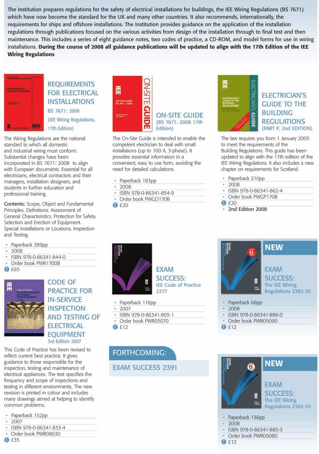
3 17th EDITION 1 17TH EDITION LAUNCHED Special Locations includes new requirements for bathrooms by Geoff Cronshaw BS 7671:2008 Requirements for Electrical Installations, IEE Wiring Regulations 17th Edition was published in January this year. Installations designed after the 30th June 2008 are to comply with BS 7671:2008. The 17th Edition includes a new Part 7 (Special Locations), which includes new requirements for bathrooms. All those involved in electrical installation work need to be familiar with these new requirements. Help is at hand, in the form of a new edition of IEE Guidance Note 7 (Special Locations), available soon. Section 701, Locations containing a bath or shower Scope The particular requirements of this section apply to the electrical installations in locations containing a fixed bath (bath tub) or shower and to the surrounding zones as described in the Wiring Regulations. The Regulations do not apply to emergency facilities, e.g. emergency showers used in industrial areas or laboratories. For locations containing a bath or shower for medical treatment, special requirements may be necessary. What s new? Changes to the zonal system, RCD protection on all bathroom circuits, 230v socket outlets permitted 3 m horizontally from the boundary of zone 1; supplementary equipotential bonding may be omitted subject to the Regulations being met. The zonal system The Regulations state: Horizontal or inclined ceilings, walls with or without windows, doors, floors and fixed partitions may be taken into account where these effectively limit the extent of locations containing a bath or shower as well as their zones. This is similar to current requirements in the 16th Edition except that the actual location containing the bath or shower is mentioned as well as the zones. The zones are similar to current requirements in the 16th Edition except for the omission of zone 3, also that zone 2 no longer extends above zone 1. Zone 1 has been extended from 0.6 m in the 16th Edition for showers without a basin for a fixed water outlet to a distance of 1.20 m from the centre point of the water outlet. Demountable shower heads are no longer mentioned. IEE Wiring Matters Spring 08
4 17th EDITION 2 Ceiling zone 2 Window recess zone 2 Outside zones zone 1 Window recess zone 2 zone m Outside zones zone 0 zone m Figure 1: Zone dimensions - elevation view showing a bath tub * 0.60 m Window recess zone 2 Zone 1 is now limited by the horizontal plane corresponding to the highest fixed shower head or water outlet or the horizontal plane lying 2.25 m above the finished floor level, whichever is higher. RCD Protection Regulation now requires that additional protection shall be provided for all circuits of the location by the use of one or more RCDs having the characteristics specified in Regulation This is a significant change. Previously ( ), only fixed current using equipment (other than electric showers) located in zone 1 required 30mA RCD protection and current using equipment (other than fixed current using equipment such as a washing machine, if suitable for use in a bathroom, connected through a fused connection unit) in zone 3 required 30mA RCD protection. Regulation means that all circuits, including lighting, electric showers, heated towel rails, etc., will require RCD protection, not exceeding 30 ma. 230 volt socket-outlets Another significant change is introduced by Regulation This now permits 230v socket-outlets Figure 2: Zone dimensions - plan view showing a bath tub zone 1 zone m Figure 3: Zone dimensions - plan view showing a shower without a basin Fixed water outlet Wiring Matters is produced by IET Services Limited, a subsidiary of The Institution of Engineering and Technology (IET), for the IET. Michael Faraday House, Six Hills Way, Stevenage, Herts, SG1 2AY, United Kingdom Tel: +44 (0) Fax: +44 (0) Advertising Sales D Smith +44 (0) daniellesmith@theiet.org Editor G D Cronshaw +44 (0) gcronshaw@theiet.org Contributing Editors M Coles, J Elliott, J Ware Design Sable Media Solutions IEE Wiring Matters is a quarterly publication from the Institution of Engineering and Technology (IET). The IET is not as a body responsible for the opinions expressed. 2008: The Institution of Engineering and Technology. All rights reserved. No part of this publication may be reproduced, stored in a retrieval system, or transmitted in any form or by any means without the permission in writing of the publisher. Copying of articles is not permitted except for personal and internal use. Multiple copying of the content of this publication without permission is always illegal. Web-offset printing by Wyndeham Heron, The Bentall Complex, Colchester Road, Heybridge, Maldon, Essex, UK Co-operating Organisations The Institution of Engineering & Technology acknowledges the contribution made by the following organisations in the preparation of this publication: British Electrotechnical & Allied Manufacturers Association Ltd R Lewington, P D Galbraith, M H Mullins Department for Communities and Local Government I Drummond Electrical Contractors Association D Locke, S Burchell City & Guilds of London Institute H R Lovegrove Energy Networks Association D J Start Electrical Contractors Association of Scotland SELECT D Millar, N McGuiness Health & Safety Executive K Morton Electrical Safety Council ERA Technology Limited M Coates British Cables Association C Reed Scottish Building Standards Agency DTI D Tee CORGI P Collins GAMBICA M. Hadley, A. Sedhev. ISSN X IEE Wiring Matters Spring 08 WRRFP81


5 The UK s First 17th Edition Multi- Function Tester 9083P The all new 9083P Multi-Function Tester has been designed to meet the requirement of the new 17th Edition, the current Part P requirements and is fully compliant with the performance requirements of BS EN It also incorporates many features that end users have requested. The unique high speed RCD-LOC feature allows loop testing without tripping and type of RCD. Continuity test - with auto null facility to zero out lead resistance RCD testing - trip time, trip current, ramp current Prospective short circuit current - direct readout of PSCC 100, 250, 500V - insulation measurement test voltages Loop Impedance - unique loop test principal will not trip any RCD RCD auto test - test RCD s in auto mode without going back to the tester Integrated socket polarity test Fully protected - against damage when accidently connected across phases Manufactured in the UK FREETM CombiVolt DL6790 worth When you buy a 9083P (Offer ends 30/04/08) 2 For a full range catalogue - Freefone: Freefone: Freefax: sales@dilog.co.uk Web:

6 17th EDITION 4 to be installed in a room containing a bath or shower providing they are installed 3 m horizontally from the boundary of zone 1. This change resolves the ambiguity that existed between locations containing a bath or shower and a bedroom containing a shower. Supplementary equipotential bonding Regulation introduces a further significant change regarding supplementary equipotential bonding. The Regulation states that where the location containing a bath or shower is in a building with a protective equipotential bonding system in accordance with Regulation , supplementary equipotential bonding may be omitted where all of the following conditions are met: (i) All final circuits of the location comply with the requirements for automatic disconnection according to , and (ii) All final circuits of the location have additional protection by means of an RCD in accordance , and (iii) All extraneous-conductive-parts of the location are effectively connected to the protective equipotential bonding according to This means the designer needs to make an assessment that all extraneous-conductive-parts of the location are effectively connected to the protective equipotential bonding according to NOTE: The effectiveness of the connection of extraneous-conductiveparts in the location to the main earthing terminal may be assessed, where necessary, by the application of Regulation Regulation states: Where doubt exists regarding the effectiveness of supplementary equipotential bonding, it shall be confirmed that the resistance R between simultaneously accessible exposed-conductive-parts and extraneous conductive-parts fulfils the following condition: R 50 V/Ia in a.c. systems R 120 V/Ia in d.c. systems where Ia is the operating current in amperes of the protective device for RCDs, IΔn, for overcurrent devices, the current causing automatic operation in 5 s. External influences The Regulations state: Electrical equipment exposed to water jets, e.g. for cleaning purposes, shall have a degree of protection of at least IPX5. The Regulations no longer limit the IPX5 requirement to communal baths or communal showers. There are no particular ingress protection requirements beyond zone 2. This means that BS 1363 accessories, such as switches and fused connection units, can be installed beyond zone 2, subject to the requirements of Regulation (external influences). Current-using equipment The 16th Edition made a clear division between equipment permitted to be installed in zone 1 and equipment permitted to be installed in zone 2. In the 17th Edition no requirements are stated for zone 2. This is because all circuits of the location now require RCD protection. The term current-using equipment other than fixed current-using equipment no longer appears in the 17th Edition. Current-using equipment, such as washing machines and tumble dryers for example, continue to be allowed to be installed beyond zone 2, subject to manufacturers approval similar to the 16th Edition. Such equipment must be supplied by means of a fused connection unit within 3 m horizontally from the boundary of zone 1. Beyond 3 m they may be supplied by means of a plug and socket-outlet. Shaver supply units The minimum degree of protection for equipment installed in zones 1 and 2 is IPX4 or IPX5 where water jets are likely to be used for cleaning purposes. An exception to this requirement is a shaver supply unit complying with BS EN Chapter 2, Section 1, which, although it does not meet the requirements of IP4X, is permitted in zone 2 but must be located where direct spray from showers is unlikely. This type of shaver supply unit, which incorporates a safety isolating transformer, is the only type which is permitted in a bathroom or shower room. More information. For more information please refer to the 17th Edition of the Wiring Regulations. Also, help is at hand, in the form of a new edition of IEE Guidance Note 7 (Special Locations) available soon. IEE Wiring Matters Spring 08


7 543.7 are also known to create currents in protective conductors. Faulty and interconnected equipment can also create protective conductor currents. In reality, considering that many modern "intelligent" electrical items such as washing machines, refrigerators, A/V equipment, etc., have embedded computer-processing, protective conductor currents are very common and not just a problem for industrial or commercial applications. Essentially, the requirements of are related to the levels of protective conductor current : by is a new group of regulations which replaces the now deleted Section 607 Earthing requirements for the installation of equipment having high protective conductor currents. Section 607 was previously a Special Location in Part 6 of BS 7671 but, as this type of installation is commonplace, the requirements are now included within the main body of the Regulations as it is no longer considered to be a special location or installation. Overview Some items of electrical equipment are designed to have a current flowing in the protective conductor when in use; these currents are often created by switch-mode power-supplies. Mark Coles This article looks at Earthing requirements for the installation of equipment having high protective conductor currents - a new group of regulations included in BS 7671:2008 Requirements for Electrical Installations, The IEE Wiring Regulations 17th Edition. Commonly, IT (Information Technology) or computer-processing equipment use switch-mode powersupplies in applications where a particular voltage is required for operation. Other items, such as electronic ballasts in high-frequency fluorescent luminaires or variable speed drives Courtesy of Reddilight Limited Individual items Individual items of electrical equipment having a protective conductor current exceeding 3.5 ma but not exceeding 10 ma shall be either permanently connected to the fixed wiring of the installation or connected by means of a plug and socket-outlet complying with BS EN , and Accumulative current in the circuit Where the accumulative protective conductor current in a final or distribution circuit is likely to exceed 10 ma, a high integrity connection shall be provided. Levels of protective conductor current The levels of expected protective conductor current will vary depending on the type of electrical equipment. BS EN Household and similar electrical appliances - Safety - Part 1: General requirements states the fundamental conditions to which items of electrical equipment are manufactured and, hence, should perform when used under normal operating conditions. Clause 13.2 of BS EN states that after the appliance has been operated for a duration corresponding to the most unfavourable conditions of normal use, the leakage current (protective conductor current) shall IET Wiring Matters Spring 08


8 not exceed the values shown in figure 1. For terminology purposes, the term "high" protective conductor current is used when values of current exceed 3.5 ma flowing in the protective conductor. The dangers Where a current flows in a protective conductor, a voltage will present along the length of the conductor and Ohm s law dictates the size of the potential difference. If the connection to the means of earthing is lost then the metallic chassis of the electrical equipment will rise in potential in respect to Earth. Should a person or livestock make contact with the metallic chassis then current is likely to flow resulting in an electric shock. All Class of equipment Portable, handheld, movable, etc. equipment Stationary equipment Protective conductor current (ma) II I 0.5 III 0.5 I 0.75 I motor-operated appliances I heating appliances Figure 1: Leakage currents as stated in Clause 13.2 of BS EN ,75 ma, or 0,75 ma per kw rated power input of the appliance with a maximum of 5 ma, whichever is higher The requirements of Regulation requires that individual items of electrical equipment having a protective conductor current above 3.5 ma but not exceeding 10 ma should be either permanently connected to the fixed wiring, see figure 2, of the installation or connected by means of a plug and socket-outlet, see figure 3, complying with BS EN An earth monitoring system to BS 4444 An earth monitoring system to BS 4444 (see figure 4) installed which, in the event of a continuity fault occurring in the protective conductor, automatically disconnects the supply to the equipment. Figure 2: Example of a method of permanent connection to fixed wiring - a fused connection unit Courtesy of MK Phase Figure 3: Example of connection using socket-outlet to BS EN Courtesy of MK Proving unit A Protected equipment The connection of equipment The table shown in figure 5 (overleaf), shows the level of protective conductor current with the requirements of BS 7671:2008 for equipment. Final and distribution circuits The table overleaf in figure 6 shows the requirements of BS 7671:2008 for every final circuit and distribution D Neutral CPC A = Alarm A = Alarm D = Relay contacts D = Relay contacts V = Low voltagev supply = Low voltage supply S = Sensing device S = Sensing device V Figure 4: Simplified circuit for an earth proving unit S Pilot conductor IET Wiring Matters Spring 08

9 The end of the pencil Winner of the 2007 Electrical Industry Award for the test and measurement product of the year NEW Megger MFT1553 multifunction tester with Bluetooth and PowerSuite On-site Does it spell the end of the pencil? Readings are sent from the MFT1553 to your smart phone, PDA or laptop at the press of a button Certificates held on the mobile devices are completed automatically, on-site as you go The full certificate can be completed on-site At the end of the day all that is needed is printing and invoicing Why waste your time filling out certificates when you get home? Find out more call now The words PowerSuite and Megger are registered trademarks The Bluetooth word mark and logo are owned by the Bluetooth SIG, Inc. and any use of such marks by Megger is under license Megger Limited Archcliffe Road Dover CT17 9EN UK T +44 (0) F +44 (0) E uksales@megger.com
10 Regulation number BS 7671:2008 Current (ma) The requirements of BS 7671:2008 Common rules Chapter 51 0 No further requirements Equipment shall be permanently connected to the installation or by means of a plug and socket-outlet to BS EN Equipment shall be permanently connected to the installation, the distribution and final circuits shall be a single CPC 10 mm² minimum or a single copper conductor, 4 mm² minimum with mechanical protection or two individual CPCs or Where CPCs are part of a multicore cable, the sum of all conductors shall not be less than 10 mm² monitored by an earth monitoring device to BS 4444 In the event of CPC continuity failure, the supply is automatically disconnected connected by a flexible cable with a plug and socket-outlet to BS EN the CPC of the flexible cable not less than: 2.5 mm² for 16 A plugs 4 mm² for plugs 32 A and above the CPC of the flexible cable not less than the line conductor a protective conductor In the event of CPC complying with Section 543 continuity failure, the generally and monitored by supply is automatically an earth monitoring device to disconnected BS 4444 (see figure 4) Figure 5: Table showing the requirements of BS 7671 in relation to protective conductor current of equipment circuit intended to supply one or more items of equipment, such that the total protective conductor current is likely to exceed 10 ma: Residual Current Devices Regulation requires that socket outlets, not exceeding 20 A, that are for use by ordinary persons intended for general use, are protected by an RCD rated at 30 ma or less, with an operating time not exceeding 40 ms at a residual current of 5 IΔn; an exception is permitted if the socketoutlets are under the supervision of skilled or instructed persons. When designing such circuits, the designer must be aware of the type of equipment likely to be supplied. Accumulative high protective conductor currents, in addition to starting surges when many items are energised simultaneously, can cause the RCD to operate. As there is no testing requirement between 0.5 IΔn and IΔn, it is fair to assume that a 30 ma RCD could operate at any level of residual current greater than 15 ma. Therefore, it would be pertinent to design high protective conductor currents for any circuit protected by an RCD rated at 30 ma at a level no greater than 15 ma. See Guidance Note 3 for more information on the testing of RCDs. Labelling at distribution boards Circuits at distribution boards with high protective conductor currents are to be labelled accordingly so that persons working on the distribution boards can maintain the protective precautions taken. The labelling information is to be in accordance with Regulation Where a circuit has or is likely to have a high protective conductor current, the protective conductor connection arrangements at the distribution board will be affected by, IET Wiring Matters Spring 08
 543.7.1.3 >10 The requirements of BS 7671:2008 a single CPC 10 mm²")


11 CALL CLICK VISIT TRADE COUNTER, open 7 days a week Are you in on the trade secret? Regulation number BS 7671:2008 Current (ma) >10 The requirements of BS 7671:2008 a single CPC 10 mm² minimum The wiring of every or final circuit and distribution circuit intended to supply one or more items of equipment, such that the total protective conductor current is likely to exceed a single copper 10 ma, shall have a high integrity conductor, 4 mm² minimum protective connection complying with one or with mechanical protection more of the following: or two individual CPCs Figure 6: Table showing the requirements of BS 7671 in relation to the protective conductor current of circuits for example, the sequence of connections. Regulation requires that where two protective conductors are utilised they are to be terminated independently of each other at all connection points, including accessories. This may pose a problem at the earth bar of the distribution board, i.e. there may not be an adequate number of spare ways to terminate conductors separately. Some large distribution boards may be provided with many spare terminals on the earth bar, whilst some manufacturers may supply an accessory kit to add extra ways. Where this is not an option, the following solution is one method of meeting the requirements: The example is that the electrical installation has a six-way distribution/consumer unit and consists of six circuits: or monitored by an earth monitoring device to BS 4444 (see figure 4) Where CPCs are part of a multicore cable, the sum of all conductors shall not be less than 10 mm² In the event of CPC continuity failure, the supply is automatically disconnected TOP BRANDS 24V SDS Plus Hammer Drill SAVE Function 2 x 2.0Ah Ni-Cd Batteries 1hr Charger Carry Case QUOTE: Piece VDE Slip-Stop Screwdriver Set Slip-Stop Blades Laser Grooved Tips Certified to EN Contents: Slotted 0.4 x 2.5 x 80mm, 0.6 x 3.5 x 100mm, 0.8 x 4 x 100mm, 1 x 5.5 x 125mm. Pozi #1 x 80mm, #2 x 100mm. 0.5 x 3.0 x 70mm mains tester and rack. QUOTE: SAVE TIME! Cable Rod Access Kit Super Deluxe Set 10 x 1m Adoxim 4 TM Rods 3 Grades of Flexibility Super Beam Includes 8 Attachments QUOTE: TEXT SCREWFIX TO FOR YOUR NEAREST TRADE COUNTER. Standard text rate applies. Max 1 per customer. Not available with any other offer or discount. All prices include VAT. Each Was V TESTED Each Ex-VAT Each Ex-VAT Quote WIRING TRADE COUNTERS - NOW OPEN CALL IN TODAY! IET Wiring Matters Spring 08

. Regulation 543.7.1.5 requires that information is provided at the distribution board indicating those circuits having a high protective conductor current (see figure 8).")
12 DB 1 1 Ring final circuit with high protective conductor current 2 Radial circuit with high protective conductor current 3 Ring final circuit 4 Radial circuit 5 Radial circuit 6 Radial circuit Regulation requires that where two protective conductors are used on circuits with high protective conductor currents, they are to be terminated into separate ways on the earth bar. By installing circuits 1 and 2 across two-ways of the earth bar, in addition to marking each conductor with the correct circuitidentification ferrule, there is no ambiguity as to the function of each conductor (see figure 7). Regulation requires that information is provided at the distribution board indicating those circuits having a high protective conductor current (see figure 8). Further information Guidance Note 1 Guidance Note 3 Guidance Note 5 Figure 7: Termination of circuits with high protective conductor currents at the earth bar DB1 The following circuits have high protective conductor current: 1 Ring final circuit with high protective conductor currents 2 Radial circuit with high protective conductor currents Thanks to MK (mk.technical@honeywell.com) and Reddilight Limited (info@reddilight.co.uk) for the images used. Figure 8: Information in accordance with Regulation indicating those circuits with high protective conductor current IET Wiring Matters Spring 08


13 Positive Solutions Smart Connect Light Air GET lifestyle solutions include smart wireless lighting control, CCTV, wiring accessories, circuit protection, lighting and air movement products. t: f: Great rates on van and tradesman liability insurance! Call FREE Quote Ref: WIRING/M Free breakdown assistance for vehicles up to 3.5 tons Public Liability from 1 milllion to 10 million Easy to set up over the phone No forms to fill in Monthly instalments available Call Monday to Friday 9am-7pm Also available: Home Insurance & Car Insurance Towergate Risk Solutions is a trading name of Towergate Underwriting Group Limited. Authorised and regulated by the Financial Services Authority. 2898/031/AD/02.08/7263
14 TESTING OF RCDS 12 17th EDITION REQUIREMENTS FOR THE TESTING OF RCDs by Jon Elliott The 17th Edition of the Wiring Regulations (BS 7671: 2008) will introduce a number of new requirements for the installation of RCDs, therefore it is timely to look at the requirements within the 17th Edition for verification of RCDs. The continuing effectiveness of these RCDs needs to be confirmed periodically. This article discusses the verification required where RCDs are used to provide automatic disconnection of supply in the event of a fault and additional protection. It should be stated at this point that the 17th Edition does not introduce any significant changes in the requirements for the testing of RCDs even where they are installed to provide automatic disconnection in the event of a fault. Use of RCDs to achieve automatic disconnection in case of a fault requires (in most cases) that a protective device shall interrupt the supply to a line conductor of a circuit or equipment in the event of a fault of negligible impedance between said line conductor and an exposedconductive-part or a protective conductor for the circuit or equipment within the appropriate required disconnection time. A disconnection time of 5 seconds for distribution equipment and final circuits of rating exceeding 32A is permitted by Similarly, a disconnection time of 1 second for distribution equipment and final circuits of rating exceeding 32 A is permitted by states that the maximum disconnection times of Table 41.1 shall be applied to final circuits not exceeding 32 A. Table 41.1 gives the maximum disconnection times for final circuits not exceeding 32 A of varying nominal voltages forming part of an installation having either TN or TT system earthing. These disconnection times may be met by the use of fuses, circuit breakers (formerly known as MCBs) or RCDs states that where an RCD is used to meet the requirements of , that is, to provide the required disconnection time, the maximum values of earth fault loop impedance in Table 41.5 may be applied. The maximum permissible earth fault loop impedances (Zs) to ensure RCD operation for non-time delayed RCDs protecting final circuits not exceeding 32 A are given in Table 41.5, a new table introduced in the 17th Edition, which is reproduced below. Where an RCD is employed to achieve the disconnection time required by Table 41.1, it is necessary to satisfy ourselves that the maximum earth fault loop impedance (Zs) stated for a particular sensitivity of RCD in Table 41.5 is not exceeded in the circuit to which they provide protection. This is in effect the same procedure that we applied in earlier editions where fuses or circuit breakers were used to achieve the necessary disconnection time and indeed continue to apply for fuses and circuit breakers in the 17th Edition. Regardless of which type of protective device is used to achieve the disconnection times required by Table 41.1, whether fuse, circuit breaker or RCD, there is no requirement to confirm that the required disconnection time can be achieved by testing the protective device. Rather, we confirm that the earth fault loop impedance of the protected circuit does not exceed the relevant tabulated maximum earth fault loop impedance for the type / sensitivity of the protective device intended to provide the required disconnection time. Rated residual operating current (ma) Maximum earth fault loop impedance Zs (ohms) 50 V < U V 120 V < U V 230V < U V U 0 > 400 V * 1667* 1533* 1667* * 500* 460* 500* Table 1: Maximum earth fault loop impedance (Zs) to ensure RCD operation in accordance with Regulation for non-delayed RCDs to BS EN and BS EN for final circuits not exceeding 32 A IET Wiring Matters Spring 08

15 17th Edition requirements for testing of RCDs The 17th Edition has the following requirements in terms of verification of installed RCDs: requires the effectiveness of automatic disconnection of supply by RCD to be verified using test equipment meeting the requirements of BS EN (Electrical safety in low voltage distribution systems up to 1000 V a.c. and 1500 V d.c. Equipment for testing, measuring or monitoring of protective measures. Residual current devices (RCD) in TT, TN and IT systems). This is to confirm that the relevant requirements of Chapter 41 (Protection against electric shock) are met. BS EN has requirements for the following tests to be applied to RCDs: - Non-tripping (50%) test - Tripping (100%) test - 5 IΔn (500%) test requires the effectiveness of the integral test facility of an RCD to be verified states that where an RCD having an IΔn of 30 ma or less is installed to provide additional protection, its operating time should not exceed 40 ms at a residual current of 5 IΔn. Recommended test procedures Although the following tests are not required by BS 7671: 2008 they are a method of establishing that the device meets the requirements of Chapter 41. Remember, in order for reliable results to be obtained when performing these tests, any loads should be disconnected from the circuits and/or outlets under test. Non-tripping test. The purpose of this test is to confirm that an RCD of any type or trip rating is not overly sensitive and is a measure intended to enable unsuitable RCDs to be identified and removed from service. The continued presence of overly sensitive RCDs tends to reduce user confidence in such devices and may encourage the adoption of potentially dangerous practices such as the bridging-out of RCDs in order to avoid unwanted tripping. The introduction of the 17th Edition of the Wiring Regulations on the 1 st January 2008 has major implications for all Electrical Contractors, Designers and Consultants. Hager has created the Consumer Unit Guide to the 17 th Editon to guide you through these changes. Order your copy online from Test procedure - With a leakage current equal to 50% of the rated residual operating current (IΔn ) applied, the RCD should not operate. Tripping current test The purpose of this test is to confirm that the residual IET Wiring Matters Spring 08

16 TESTING OF RCDS 14 operating current of the protective device is less than or equal to the rated residual operating current. This is a measure of the continued effectiveness of the device to work as required by BS 7671 and in accordance with its product specification when installed for the purpose of providing automatic disconnection in the event of a fault. It does not demonstrate its suitability in terms of providing additional protection. The test should be performed in both the positive and negative half-cycles. Test procedure - 100% of the rated time delay plus 200 ms. Test to confirm suitability for use to provide additional protection The purpose of this test is to confirm the continued suitability of an RCD having a rated residual operating current (IΔn) not exceeding 30 ma to provide additional protection under no-fault conditions (in the 16th Edition, this was known as supplementary protection against direct contact). The test should be performed in both the positive and negative half-cycles. General purpose RCD to BS EN and RCBO to BS EN With a leakage current flowing equivalent to 100% of the rated residual operating current (IΔn) of the RCD, operation should occur within 300 ms. S type RCD to BS EN (incorporating an intentional time delay) With a leakage current flowing equivalent to 100% of the rated residual operating current (IΔn) of the RCD, operation should occur within a time range from 130 ms to 500 ms. General purpose RCD to BS 4293 and RCD protected socket-outlets to BS 7288 With a leakage current flowing equivalent to 100% of the rated residual operating current (IΔn) of the RCD, operation should occur within 200 ms. General purpose RCD to BS 4293 incorporating an intentional time delay With a leakage current flowing equivalent to 100% of the rated residual operating current (IΔn) of the RCD, operation should occur within a time range from 50% of the rated time delay plus 200 ms to Test procedure - With a leakage current flowing equivalent to 500% of (i.e. 5 times) the rated residual operating current (IΔn) of the RCD, operation should occur within 40 ms. Confirmation of the effectiveness of the integral test facility RCDs have an integral test device to simulate the passing through the detecting device of a residual current. This makes possible periodic testing of the ability of the residual current device to operate. However, it should be remembered that operation of the integral test button merely confirms the continuing functioning of the electrical and mechanical components of the RCD. It does not confirm that the device is capable of operating in accordance with the specification of the relevant product standard or, indeed the requirements of BS Test procedure - With the supply to the RCD switched on and with the RCD in the on position, the button marked T or Test on the RCD is pressed. The RCD should switch off recommends that the integral test button of an RCD is pressed quarterly (every 3 months). Courtesy of MK Summary RCDs should be tested at 50%, 100% and, if providing additional protection 500% of their rated residual operating current (IΔn). In addition, the integral test device should be operated quarterly. Where an RCD is employed to achieve the disconnection time required by Table 41.1 it is necessary to confirm that the maximum earth fault loop impedances (Zs) stated for a particular sensitivity of RCD in Table 41.5 are not exceeded in the circuit to which they provide protection. More in depth descriptions of both RCD and earth fault loop impedance testing procedures are given in IEE Guidance Note 3 Inspection and testing. A revised version reflecting the changes brought about by the advent of the 17th Edition will be available in July IET Wiring Matters Spring 08


17 Project2:Layout 1 4/3/08 10:31 Page 1 Wednesday, 09 April 2008 The IET, Savoy Place, London, UK The Institution of Engineering and Technology L CHNICA FREE TE OGRAMME PR R A IN SEM NS REVISIO MES E EDITION - 17TH T PERSON SCH ING ST E TEN T E P IC M D O RIO -C STIC PE - DOME D REPORTING AN April NEC, Birmingham The Impact of the 17th Edition of the IEE Wiring Regulations Opening hours: Tuesday and Wednesday: Thursday: Primary partners In association with AVOID THE QUEUES BY REGISTERING IN ADVANCE AT This seminar is key to inform delegates of the vital changes from the 17th Edition of the IEE Wiring Regulations. ONE PLACE ONE WEEK THE WHOLE OF MANUFACTURING WILL BE THERE Co-located events: Sponsored by For more information and to register, please visit: DFA Media Ltd. Cape House. 60a Priory Road. Tonbridge TN9 2BL tel: fax: info@dfamedia.co.uk IEE Wiring Matters Spring 08
 because of a potential difference created by the passage of fault")
18 SHOCK PROTECTION 16 become live under fault conditions. The potential of the metal enclosure is higher than that of the main earthing terminal of the installation (and that of Earth) because of a potential difference created by the passage of fault current through the impedance of the circuit protective conductors and the means of earthing. PROTECTION AGAINST ELECTRIC SHOCK by John Ware THE FUNDAMENTAL rule of protection against electric shock is: live parts, such as energized conductors, must not be accessible, and conductive parts which are accessible, such as metal enclosures of equipment or metal pipes, must not be hazardous-live These two conditions must be achieved both in normal conditions (no faults on the electrical system) and under single fault conditions (such as a fault from a live conductor to a metal casing). Protection under normal conditions Protection under normal conditions is achieved by basic protection, formerly known as protection against direct contact. Protection under single fault conditions is achieved by fault protection and was previously referred to as protection against indirect contact. Basic protection is defined as: Protection against electric shock under fault-free conditions Basic protection is provided to protect persons or livestock coming into direct contact with live parts. A live part is defined as: A conductor or conductive part intended to be energized in normal use, including a neutral conductor but, by convention, not a PEN conductor Figure 1 illustrates a person coming into contact with live parts. Protection under fault conditions or fault protection is defined as: Protection against electric shock under single fault conditions Fault protection provides protection against persons or livestock coming into contact with exposed-conductiveparts which have become live under single fault conditions. An exposedconductive-part is defined as: Conductive part of equipment which can be touched and which is not normally live but which can become live when basic insulation fails Figure 2 illustrates how a person could receive an electric shock under single fault conditions. The person in Figure 2 is in contact with the metal enclosure of an item of Class I electrical equipment which has Protective measures A protective measure must consist of provision of basic protection and provision of fault protection, which normally are independent. For example, in the case of automatic disconnection of supply, basic protection is provided by insulation and barriers and enclosures while fault protection is provided by protective earthing, protective bonding and automatic disconnection of supply. Basic and fault protection are independent. Enhanced protective measure A permitted exception is where the protective measure is an enhanced protective measure which provides both basic and fault protection. An example of an enhanced protective measure is reinforced insulation. Basic protection and fault protection are both provided by the reinforced insulation (Refer to Regulation ). Recognized protective measures BS 7671: 2008 recognizes the protective measures listed in Table 1 ( see page 22). The protective measure of Automatic Disconnection of Supply The protective measure of automatic disconnection of supply consists of basic protection, fault protection and, for some circuits and locations, additional protection. Basic protection is provided by basic insulation of live parts and/or by barriers or enclosures. Fault protection is provided by (i) protective earthing, (ii) main protective equipotential bonding, and IET Wiring Matters Spring 08


19 SHOCK PROTECTION (iii) automatic disconnection of supply in the case of a fault. 17 Protective earthing Protective earthing requires all exposedconductive-parts to be connected to a protective conductor which in turn is connected to the main earthing terminal and hence, via the earthing conductor to the means of earthing. Main protective equipotential bonding In each installation main protective bonding conductors complying with Chapter 54 are required to connect to the main earthing terminal extraneous-conductive-parts, such as water and gas installation pipes, other installation pipework and ducting, central heating and air conditioning systems and exposed metallic structural parts of the building. Figure 1: Contact with live parts Figure 2: Single fault conditions Automatic disconnection in case of a fault When a fault occurs, the fault current has to be of sufficient magnitude to operate the circuit protective device to automatically disconnect the supply to the faulty circuit within a prescribed time. A protective device such as a fuse, circuit-breaker or RCD is to be provided and the circuit designed such that the device operates and disconnects the supply. In the event of a fault of negligible impedance between a line conductor and an exposed-conductive-part or a protective conductor, the protective device must disconnect the supply within the appropriate time stated in Table 41.1 of BS 7671 (See Table 2, page 22). Requirements of the protective measure of Automatic Disconnection of Supply include protective earthing, main protective equipotential bonding and automatic disconnection. TN systems In a TN system each exposedconductive-part of the installation is Figure 3: Automatic Automatic Disconnection of Supply required to be connected by a protective conductor to the main earthing terminal of the installation which must be connected to the earthed point of the power supply system, i.e. the supply transformer. The characteristics of the protective device and the circuit impedances are required to fulfil the following requirement (Regulation ): Zs x Ia Uo where: Zs is the impedance in ohms (Ω) the fault loop comprising: the source the line conductor up to the point of the fault, and the protective conductor between the point of the fault and the source. Ia is the current in amperes (A) causing the automatic operation of the disconnecting device within the time specified in Table 41.1 of BS Uo is the nominal a.c. rms or d.c. line voltage to Earth in volts (V) which is 230 V. TT system In a TT system, every exposedconductive-part is required to be connected, via the main earthing terminal to a common earth electrode (Regulation refers). The preferred protective device for fault protection is an RCD (Regulation ) but where an RCD is used, as it will be in most cases, overcurrent protection must nonetheless be provided by a fuse or a circuitbreaker, or, alternatively a combined RCD and overcurrent protective device IET Wiring Matters Spring 08
20 IET PUBLICATIONS
21
22


23 Your first choice for building maintenance Quality products from Leading Manufacturers In house calibration 48 hours turn around Guaranteed same or next day delivery Free Technical Support Flexible discounts for large orders WEEE Compliant rswww.com/buildings
24 SHOCK PROTECTION 22 Protective measure Use Basic protection provided by Fault protection provided by Fault protection provided by Automatic disconnection of supply General Insulation or barriers and enclosures Protective earthing Protective bonding Automatic disconnection Used in 95% of all installations. Section 411 in BS 7671: Includes FELV (411.7) and RLV (411.8) Double or reinforced insulation General Basic insulation Supplementary insulation Section 412 Reinforced insulation Electrical separation for the supply to one item of current-using equipment General Insulation or barriers and enclosures Simple separation of the circuit from other circuits and Earth Section 413 Extra-low voltage (SELV and PELV). General Voltage must not exceed 50 V a.c. Supply from a suitable source Separation Obstacles Controlled or supervised by skilled persons With SELV the circuit is separated, with PELV it is earthed Section 414. Obstacles With or without Fault protection Refer to Regulations and Placing out of reach Placing out of reach Refer to Regulation Non-conducting location Earth-free local equipotential bonding Electrical separation for the supply to more than one item of current-using equipment Installation is controlled or under the supervision of skilled or instructed persons so that unauthorized changes cannot be met Insulation or barriers and enclosures The conditions of supervision under which the fault protective provisions of Section 418 may be applied as part of the protective measure are given in Regulation Refer to Regulation Refer to Regulation Refer to Regulation Table 1: Recognized protective measures (an RCBO) may be employed. Where an RCD is used for fault protection, the following conditions are to be fulfilled: the disconnection time must be that required by Table 41.1, and R A x IΔn 50 V Where: R A is the sum of the resistances of the earth electrode and the protective conductor connecting it to the exposed-conductive-parts (in ohms). IΔn is the rated residual operating current of the RCD. Additional protection BS 7671 recognizes this measure as reducing the risk of electric shock in the event of failure of one or other of the two basic protective measures mentioned above (insulation and barriers or enclosures) and/or failure of the provision for fault protection or carelessness by users. The measure must not be used as the sole means of protection and does not obviate the need to apply one of the protective measures specified in Sections 411 Automatic disconnection Final circuit not Final circuit Distribution exceeding 32 A exceeding 32 A circuit TN system 0.4 s 5 s 5 s TT system 0.2 s 1 s 1 s TT system (1) 0.4 s 5 s 5 s (1) Where, in a TT system, disconnection is achieved by an overcurrent protective device and main bonding is connected to all the extraneous-conductive-parts within the installation in accordance with Regulation , the maximum disconnection times applicable to a TN system may be used. A maximum disconnection time of 5 s applies to all circuits in a reduced low voltage system Regulation refers). A maximum disconnection time of 5 s applies to all circuits supplying fixed equipment used in highway power supplies (Regulation refers). Table 2: Extract from Table 41.1 (and others) of BS 7671: 2008 Maximum disconnection times for a nominal a.c. rms. line voltage to Earth of 230 V of supply, 412 Double or reinforced insulation 413 Electrical separation and 414 Extra-low voltage provided by SELV or PELV; Regulation refers. Additional protection by means of a 30 ma RCD is specified as part of a protective measure for situations such as: socket-outlets for use by ordinary persons for general use ( ) mobile equipment outdoors ( ) concealed cables in walls and partitions where the installation is not intended to be under the supervision of a skilled or instructed person, ( ) circuits in circuits in certain special Locations ( ) The protective measure of Double or Reinforced Insulation Double or reinforced insulation is a protective measure in which: basic protection is provided by basic insulation, and fault protection is provided by supplementary insulation, or both basic and fault protection are provided by reinforced insulation between live parts and accessible parts (Regulation ). Double or reinforced insulation is intended to prevent the appearance of IET Wiring Matters Spring 08

25 SHOCK PROTECTION a dangerous voltage on the accessible parts of electrical equipment through a fault in the basic insulation. There is no provision for the connection of exposed metalwork of the equipment to a protective conductor, and no reliance upon the earthing arrangements in the fixed wiring of the installation. Wiring systems Wiring systems must have a rated voltage of the cable(s) is not less than the nominal voltage of the system and at least 300/500 V and adequate mechanical protection of the basic insulation must be provided by one or more of the following the non-metallic sheath of the cable, or non-metallic trunking or ducting or non-metallic conduit. The protective measure of Electrical Separation Electrical separation is a protective TRAINING measure in which basic protection is provided by basic insulation of live parts or by barriers or enclosures and fault protection is provided by simple separation of the separated circuit from other circuits and from Earth (Regulation ). The two main principles underlying protection by electrical separation is that neither the source of the supply nor any live parts of the separated circuit is connected to any other circuit or to Earth. Thus, in the event of a single fault to an exposedconductive-part of equipment in the separated circuit, fault protection is afforded because there is no path for fault current to return to the source. For an installation in a dwelling, the only likely application of the use of electrical separation is a shaver supply unit complying with BS EN Except under particular circumstances (Refer to Regulation Brought to you by the Institution of Engineering and Technology of BS 7671) this protective measure is limited to the supply of one item of current-using equipment supplied from one unearthed source with simple separation. The source of supply is an isolating transformer conforming to BS EN (which supersedes BS 3535), or one of the other sources specified in Regulation having an equivalent degree of separation from any other system. Protection by electrical separation requires the following conditions to be met: The separated circuit must be supplied through a source with at least simple separation The voltage of the separated circuit must not exceed 500 V Live parts of the separated circuit must not be connected at any point to another circuit or to Earth or to a protective conductor Power your way towards the 17th Edition 23 TRAIN TO THE 17TH EDITION These new regulations come into force July 2008: Understand the changes Upgrade courses fromthe 16th Edition to the 17th Edition 17th Edition qualifications New City & Guilds awards Meet industry standards To find out more about our short courses and workshops visit For advice on the best course to meet your needs, call +44 (0) or coursesreg@theiet.org IET Wiring Matters Spring 08
26 SHOCK PROTECTION 24 Figure 4: The principle of electrical separation Figure 5: Simple PELV system No exposed-conductive-part of the separated circuit must be connected either to the protective conductor or exposed-conductive-parts of other circuits, or to Earth. If the exposedconductive-parts of the separated circuit are liable to come into contact, either intentionally or fortuitously with the exposed-conductive-parts of other circuits, protection against electric shock no longer depends solely on protection by electrical separation but on the protective provisions to which the latter exposedconductive-parts are subject. Separated circuits The use of separate wiring systems is recommended. If separated circuits and other circuits are in the same wiring system, multi-conductor cables without metallic covering, or insulated conductors in insulating conduit, nonmetallic ducting or non-metallic trunking shall be used, provided that the rated voltage is not less than the highest nominal voltage, and each circuit is protected against overcurrent. The protective measure of Extra-Low Voltage provided by SELV or PELV Protection by extra-low voltage is a protective measure which consists of either of two different extra-low voltage systems, SELV (Separated Extra-Low Voltage), or PELV (Protective Extra-Low Voltage), Regulation refers. SELV is defined as: An extra-low voltage system which is electrically separated from Earth and from other systems in such a way that a single fault cannot give rise to the risk of electric shock PELV is defined as: An extra-low voltage system which is not electrically separated from Earth, but which otherwise satisfies all the requirements for SELV Protection by extra-low voltage provided by SELV or PELV requires all of the following: Limitation of voltage in the SELV or PELV system to the upper limit of voltage Band I which is 50 V a.c. or 120 V d.c. and Protective separation of the SELV or PELV system from all circuits other than SELV and PELV circuits, and Basic insulation between the SELV or PELV system and other SELV or PELV systems, and For SELV systems only, basic insulation between the SELV system and Earth. The extra-low voltage is generally considered insufficient to present a hazard of electric shock (as defined) in dry situations where the person protected has a body resistance within normal limits. In certain locations the requirements of Part 7 limit the value of the extra-low voltage to a value lower than 50 V a.c. or 120 V d.c. If the nominal voltage exceeds 25 V a.c. or 60 V d.c., or if the equipment is immersed, basic protection shall be provided for SELV and PELV circuits by insulation in accordance with Regulation Basic protection and fault protection is provided under the following conditions: The nominal voltage cannot exceed the upper limit of voltage Band I, and The supply is from a permitted source, and The requirements applicable to SELV or PELV circuits listed below are met. (Regulation refers). If the system is supplied from a higher voltage by equipment which provides at least simple separation between that system and the extra-low voltage system but which does not meet the requirements for a SELV and PELV source, the requirements for FELV may be applicable. For further information refer to Guidance Note 5: Protection against electric shock. IET Wiring Matters Spring 08

27 K GS5 J16U 19 3 GS1 A 11 B 10 C 9 NH 6 17th Edition U1A U1B 4066 U1D 4066 U1C IET Members Receive a 20% discount when ordering directly from the IET, remember to quote your membership number. R23 10M J16U 18 J16L 20 J16U 20 R19 J16L 17 J16U 17 74C J16L 19 U7A 74C U7F 74C UD3 100K 3 ACGND 2 4A 74C U7E QI 2N4393 GS5 13 GS GS3 7 GS2 5 GS1 3 EN2 EN1 EN GS5 GS4 GS3 GS2 GS OUT6 OUT5 OUT4 OUT3 OUT2 OUT EN4 EN3 EN EN2 EN1 Between January and September 2008, the IET will also be publishing new editions of the popular IEE Guidance Notes and On-Site Guide to accompany the 17th Edition. 1 TL062 GS5 GS4 GS3 GS2 GS1 EN2 DIS4 DIS2 GS5 GS4 GS3 GS2 U11 OUT6 OUT5 OUT4 OUT3 OUT2 OUT DIS4 DIS2 U OUT NOW TO BUY FROM THE IET Essential for all those involved in electrical installation work. To buy a copy of the new 17th Edition, buy online at or sales@theiet.org Alternatively, you can order by telephone +44 (0) To be notified when associated new Wiring Regulations books are published, please visit and submit your details OUT6 OUT5 OUT4 OUT3 OUT2 OUT DIS4 DIS2 U16 The IEE is a registered trademark of the Institution of Engineering and Technology Price 65 ISBN PWR1700B 4503 OUT6 OUT5 OUT4 OUT3 OUT2 UT IEE Electrical Courses Throughout 2008 the IET will be running a full programme of courses and associated City & Guilds exams to enable you to train to the new 17th Edition standard. To view a list of courses and book online visit U13 14 IN6 IN5 12 IN4 10 IN3 6 IN2 42 IN1 The Institution of Engineering and Technology is registered as a Charity in England & Wales (no ) and Scotland (no SCO38698) 6 5 U13


28 Only awarded for expertise Customers and employers hold NAPIT members in the highest regard. That s because only fully trained electrical engineers can join NAPIT. Their skills are their own not their supervisor s. NAPIT s Part P scheme is designed by electricians for electricians, and we offer practical help and advice on Building Regulations, Training, Self Certification and Works Notification. So if you are a highly skilled electrician, make sure you get the recognition you deserve. Join NAPIT now. Call NAPIT Administration Centre, 4th Floor, Mill 3, Pleasley Vale Business Park, Mansfield, NottinghamshireNG19 8RL Choose a Megger Multitester worth 75 or a Kewtech Clamp Meter worth 115 Or, if you are already registered with another Registration Scheme get 180 off * your initial application *Offer applies to new applicants to NAPIT who have been members of an existingregistration Scheme for 12 months. Not to be used in conjunction with any other offer. Offer expires 31 May Photos are for illustration purposes only. FREE WHEN YOU JOIN Electrical Ventilation Plumbing Heating
FIRE ALARMS. IN DWELLINGS By John Ware FIRE ALARMS
 WM_Winter 05_part1_EW.qxd 17/11/05 6:55 am Page 1 1 IN DWELLINGS By John Ware IN THE UK around 80% of all fire deaths and injuries occur in dwellings, a total of 450 to 500 deaths and 14,000 injuries per
INSPECTION AND TESTING OF ELECTRICAL INSTALLATIONS: RESIDUAL CURRENT DEVICES
 INSPECTION AND TESTING OF ELECTRICAL INSTALLATIONS: RESIDUAL CURRENT DEVICES [The basis of this article was first published in Wiring Matters in issue 15, Summer 2005 and reflected the requirements of
BS Outcomes 6
 BS7671 2015 Outcomes 6 Inspection and testing 6.1 Identify the general requirements for inspection and testing of installations 6.2 State the need for diagrams, charts or tables to be available e prior
Information Sheet LIA IS 07 Issue 1 08/2013 Page 1 of 5 For LIA members use only
 Page 1 of 5 IET Wiring Regulations Locations Containing a Bath or Shower The following briefly describes the installation rules for locations containing a bath or shower based on BS7671:2008 + Amd 1 (17th
Guide to: 17 th Edition Consumer Units
 Guide to: 17 th Edition Consumer Units Introduction For well over one hundred years the Wiring Regulations have provided the rules which must be followed to make sure that electrical installations are
Contents The IET Regulations, BS 7671, and this Guide 1.1 The need for this Electrician s Guide 1.2 The IET Regulations BS 7671
 Contents 1 The IET Regulations, BS 7671, and this Guide 1 1.1 The need for this Electrician s Guide 1 1.2 The IET Regulations BS 7671 2 1.2.1 International basis 2 1.2.2 The Seventeenth Edition 3 1.2.3
The extent of liability of the signatory/signatories is limited to the work described above as the subject of this certificate.
 This safety certificate is an important and valuable document which should be retained for future reference DETAILS OF THE CLIENT Client / DETAILS OF THE INSTALLATION Extent of the installation covered
(date) except for the departures, if any, detailed as follows: Name (CAPITALS) N/A. Name (CAPITALS) N/A
 except for the departures, if any, detailed as follows: Name (CAPITALS) N/A. Name (CAPITALS) N/A") Electrical Installation & Test Engineers DETAILS OF THE CLIENT Client / Freshco Food Stores, Kiln Park Business Estate, Milton Keynes, MK3 5FS ELECTRICAL INSTALLATION CERTIFICATE Issued in accordance with
Electrical Installation & Test Engineers DETAILS OF THE CLIENT Client / Freshco Food Stores, Kiln Park Business Estate, Milton Keynes, MK3 5FS ELECTRICAL INSTALLATION CERTIFICATE Issued in accordance with
Replacing a consumer unit in domestic premises where lighting circuits have no protective conductor
 Replacing a in domestic premises where lighting circuits have no protective conductor This is one of a series of Best Practice Guides produced by the Electrical Safety Council* in association with leading
An overview of the main proposals in BS th Edition. Electrical Contractors Association
 An overview of the main proposals in BS 7671 17 th Edition Electrical Contractors Association Why have Regulations Behold the electrician standing there. Soot, soil & verdigris defile his greasy hair.
Guide to sollysta Wiring Accessories
 Guide to sollysta Wiring Accessories Introduction This guide expands upon some of the requirements found in the 17 th Edition of the IEE Wiring Regulations and Building Regulations and how they affect
3 o/c2 The symbol used to show that a BS 88 device has a motor circuit application is a gg b gm c l z d I 2.
 Sample Questions - C&G 2382 17th Edition PaperB 1 o/c1 Electrical installation design shall take into account a electromagnetic disturbances b direct lightning strikes c current world copper prices d local
Amendment Number 3 of BS how it might affect you
 Amendment Number 3 of BS7671 2008 - how it might affect you Geoff Cronshaw provides us with a look ahead at the proposals of Amendment 3 to BS 7671:2008 IET Wiring Regulations and the resulting changes
Periodic inspection reporting - recommendation codes for domestic and similar electrical installations
 4 Periodic inspection reporting - recommendation codes for domestic and similar electrical installations This is one of a series of Best Practice Guides produced by the Electrical Safety Council* in association
Requirements for Electrical Installations
 BRITISH STANDARD BS 7671:2018 Corrigendum (December 2018) Requirements for Electrical Installations IET Wiring Regulations Eighteenth Edition The Institution of Engineering and Technology and BSI NO COPYING
3. RCCB (residual current operated circuit-breaker without integral overcurrent protection)
") RESIDUAL CURRENT DEVICE (RCD) - Contents 1. Introduction 2. General 3. RCCB (residual current operated circuit-breaker without integral overcurrent 4. RCBO (residual current operated circuit-breaker with
RESIDUAL CURRENT DEVICE (RCD) - Contents 1. Introduction 2. General 3. RCCB (residual current operated circuit-breaker without integral overcurrent 4. RCBO (residual current operated circuit-breaker with
Consumer unit replacement in domestic and similar premises
 Consumer unit replacement in domestic and similar premises 6 Issue 2 The Electrical Safety Council is indebted to the following organisations for their contribution and/or support to the development of
The Legal Obligations of Employers to Maintain all Electrical Installations in a Safe Condition
 The Legal Obligations of Employers to Maintain all Electrical Installations in a Safe Condition Issued in the interests of safety by The Legal Obligations of Employers to Maintain all Electrical Installations
WIRING MATTERS. Part P comes into force. Your questions answered. Radon Gas Swimming Pools Installing Recessed Luminaires.
 WIRING MATTERS Spring 2005 Part P comes into force Your questions answered Radon Gas Swimming Pools Installing Recessed Luminaires PART P 1 PART P COMES INTO FORCE By Geoff Cronshaw Overview Part P of
ER 52 Electrician Regulations Answer Schedule. Question 1 Marks Reference Marking notes. (1 mark) EA 147M(c)(i) (1 mark) EA 147M(c)(ii)
 EA 147M(c)(i) (1 mark) EA 147M(c)(ii)") ER 52 Electrician Regulations Answer Schedule Notes:1. means that the preceding statement/answer earns 1 mark. 2. This schedule sets out the expected answers to the examination questions. The marker can
ER 52 Electrician Regulations Answer Schedule Notes:1. means that the preceding statement/answer earns 1 mark. 2. This schedule sets out the expected answers to the examination questions. The marker can
DCP3/ DETAILS OF THE CLIENT ADDRESS OF THE INSTALLATION
 Issued in accordance with British Standard 7671 - Requirements for Electrical Installationsby a Domestic Installer enrolled with NICEIC, Warwick House, Houghton Hall Park, Houghton Regis, Dunstable LU5
Requirements for Electrical Installations
 BRITISH STANDARD BS 7671:2008 + Amendment 1:2011 (Corrigendum June 2013) Requirements for Electrical Installations IET Wiring Regulations Seventeenth Edition ISBN-13: 978-1-84919-730-4 BS 7671 Requirements
INTERNATIONAL STANDARD
 INTERNATIONAL STANDARD IEC 60364-4-41 Fifth edition 2005-12 GROUP SAFETY PUBLICATION Low-voltage electrical installations Part 4-41: Protection for safety This English-language version is derived from
Level 3 NVQ Diploma in Domestic Plumbing and Heating ( /025)
") City & Guilds Tutor Training Guidance Level 3 6189 NVQ Unit 305/025 Understand and carry out electrical work on domestic plumbing and heating systems and components April 2013 This document is for tutors
City & Guilds Tutor Training Guidance Level 3 6189 NVQ Unit 305/025 Understand and carry out electrical work on domestic plumbing and heating systems and components April 2013 This document is for tutors
Alan Wells Technical and Standards Director Certsure LLP trading as NICEIC
 Introduction Alan Wells Technical and Standards Director Certsure LLP trading as NICEIC Who are Certsure? Where do we come from? 1923 - A National Register created 1956 - NICEIC established as a Charity
Code of Practice // For the installation, inspection and testing of electrical installations tel/fax:
 Code of Practice // For the installation, inspection and testing of electrical installations tel/fax: 0870 241 7687 email: mpba@mpba.biz Introduction // This code of practice provides guidance for manufacturers,
SECTION AUTOMATIC TRANSFER SWITCHES
 PART 1 - GENERAL 1.1 DESCRIPTION SECTION 26 36 23 This section specifies the furnishing, complete installation, and connection of automatic transfer switches. 1.2 RELATED WORK A. Section 14 21 00, ELECTRIC
Requirements for Electrical Installations
 BRITISH STANDARD Draft for Public Comment BS 7671:2008 Amendment 3 Requirements for Electrical Installations Draft for Public Comment Amendment 3 IET Wiring Regulations Seventeenth Edition The Institution
INTERNATIONAL STANDARD
 INTERNATIONAL STANDARD IEC 60364-4-41 Fourth edition 2001-08 GROUP SAFETY PUBLICATION Electrical installations of buildings Part 4-41: Protection for safety Protection against electric shock This English-language
ELECTRICAL REQUIREMENTS FOR SWIMMING POOLS
 SPRING 12 ISSUE 42 WIRINGMATTERS The Institution of Engineering and Technology ELECTRICAL REQUIREMENTS FOR SWIMMING POOLS Special Locations Requirements for installations at Filling Stations 17th Edition
User Information Sheet 008 : 2010
 User Information Sheet 008 : 2010 Formerly UIS008, July 2009 ELECTRICAL INSTALLATIONS ASSOCIATED WITH BULK LPG INSTALLATIONS 1. Introduction This Information Sheet describes some of the principles and
Update all extract references to NFPA documents (including NFPA 72) in Chapter 3 and related annex material to the latest editions.
 in Chapter 3 and related annex material to the latest editions.") 11/16/12 TerraView First Revision No. 15-NFPA 720-2012 [ Global Input ] Update all extract references to NFPA documents (including NFPA 72) in Chapter 3 and related annex material to the latest editions.
11/16/12 TerraView First Revision No. 15-NFPA 720-2012 [ Global Input ] Update all extract references to NFPA documents (including NFPA 72) in Chapter 3 and related annex material to the latest editions.
SECTION AUTOMATIC TRANSFER SWITCHES
 PART 1 - GENERAL 1.1 DESCRIPTION SECTION 26 36 23 SPEC WRITER NOTE: Use this section only for NCA projects. Delete between //--// if not applicable to project. Also, delete any other item or paragraph
Special Types of Installation
 Chapter 7 Special Types of Installation Certain types of installation demand special consideration when designing and installing the electrical equipment. Part 7 of the 17th edition of the IEE Wiring Regulations
INTERNATIONAL STANDARD
 INTERNATIONAL STANDARD IEC 60364-6 First edition 2006-02 Low-voltage electrical installations Part 6: Verification This English-language version is derived from the original bilingual publication by leaving
Electrical Tech Note 107
 Electrical Tech Note 107 Biosystems & Agricultural Engineering Department Michigan State University Understanding the Construction Code Rules, Part 8 1 Based on the 2014 NEC and the 2015 MRC The State
INTERNATIONAL STANDARD
 INTERNATIONAL STANDARD IEC 60364-4-41 Fifth edition 2005-12 GROUP SAFETY PUBLICATION Low-voltage electrical installations Part 4-41: Protection for safety Protection against electric shock This English-language
ENERGY EFFICIENCY OF LUMINAIRES
 www.theiet.org/wiring AUTUMN 09 ISSUE 32 WIRINGMATTERS The Institution of Engineering and Technology ENERGY EFFICIENCY OF LUMINAIRES Future developments in the IEE Wiring Regulations Inspection and Testing
Systems of inspecting the existing building and the procedures of auditing engineering plans. M. Mostafa
 Systems of inspecting the existing building and the procedures of auditing engineering plans M. Mostafa 2 Agenda 1. Introduction 2. Why inspection? 3. Initial Verification 4. Periodic verification 5. Reference
Informational Bulletin on Mobile office Units Prepared by Mark Hilbert May 17, 2017
 Informational Bulletin on Mobile office Units Prepared by Mark Hilbert May 17, 2017 It has come to the attention of the electrical authorities having jurisdiction (AHJs) at the DOE sites there is inconsistency
Mains Power Filter 970MF10 970MF20. Installation Instructions
 Mains Power Filter Installation Instructions and Table of Contents 1.0 Warnings... 3 2.0 Introduction... 3 3.0 Quick Installation Overview... 3 4.0 Typical Installations... 3 5.0 Protection Concepts...
Guide to Condition Reports for Domestic Electrical Installations
 Guide to Condition Reports for Domestic Electrical Installations Guide to condition reports for domestic electrical installations Courtesy of Greater Manchester Fire and Rescue Service What is an electrical
AS/NZS 3190:2011 AS/NZS
 AS/NZS 3190:2016 Australian/New Zealand Standard Approval and test specification Residual current devices (currentoperated earth-leakage devices) Superseding AS/NZS 3190:2011 AS/NZS 3190:2016 AS/NZS 3190:2016
ELECTRONIC SECURITY THEORY/REGULATIONS EXAMINATION 19 November 2011
 Candidate Code No. ESAI 27 For Board Use Only Result Date Result Date Int ELECTRONIC SECURITY THEORY/REGULATIONS EXAMINATION 19 November 2011 QUESTION AND ANSWER BOOKLET Time Allowed: 3 Hours INSTRUCTIONS
INTERNATIONAL STANDARD
 INTERNATIONAL STANDARD IEC 60364-4-44 Edition 1.1 2003-12 Edition 1:2001 consolidated with amendment 1:2003 Electrical installations of buildings Part 4-44: Protection for safety Protection against voltage
BS : Amd Introduction
 BS7671 2008: Amd 3. 2015 Introduction Day 1 Course design: Who the course is for? Statutory relationships BS7671 at a glance, Major Changes New numbering system Scope and fundamental requirements Part
TESTSAFE. minipat APPLIANCE TESTER USER MANUAL
 TESTSAFE minipat APPLIANCE TESTER USER MANUAL TABLE OF CONTENTS SAFETY RULES 3 GENERAL DESCRIPTION 4-9 Overall Result 4 Earthing and Class I Appliances 5 Overall Result Class I Appliances and Cables 5
Contact Details. Please note that some of the contact details on this PDF document may not be current.
 Contact Details Please note that some of the contact details on this PDF document may not be current. Please use the following details if you need to contact us: Telephone: 0844 879 3588 Email: customer.services@gdcgroup.co.uk
Australian Standard. Degrees of protection provided by enclosures (IP Code) AS IEC Ed 2.1:2001 AS 60529
 AS IEC Ed 2.1:2001 AS 60529") AS 60529 2004 IEC 60529 Ed 2.1:2001 AS 60529 Australian Standard Degrees of protection provided by enclosures (IP Code) This Australian Standard was prepared by Committee EL-026, Protective Enclosures
AS 60529 2004 IEC 60529 Ed 2.1:2001 AS 60529 Australian Standard Degrees of protection provided by enclosures (IP Code) This Australian Standard was prepared by Committee EL-026, Protective Enclosures
Girona. Operating Instructions. Glass Panel Heaters. Models: GFP050 W/B GFP075 W/B GFP100 W/B GFP150 W/B GFP200 W/B. A world of expertise
 A world of expertise Operating Instructions These instructions should be read carefully and retained for future use. Note also the information presented on the appliance. Girona Glass Panel Heaters Models:
Bringing power to life. GUIDE TO ARC FAULT DETECTION DEVICES (AFDD)
") Bringing power to life. GUIDE TO ARC FAULT DETECTION DEVICES (AFDD) November 2017 COMPANIES INVOLVED IN THE PREPARATION OF THIS GUIDE Eaton Electric Limited 270 Bath Road, Slough, Berkshire SL1 4DX Tel:
Bringing power to life. GUIDE TO ARC FAULT DETECTION DEVICES (AFDD) November 2017 COMPANIES INVOLVED IN THE PREPARATION OF THIS GUIDE Eaton Electric Limited 270 Bath Road, Slough, Berkshire SL1 4DX Tel:
Guide to Membership Assessments
 Issue 10 July 2008 Guide to Membership Assessments 1. Introduction This guide is intended to assist companies in preparing for an assessment visit by SELECT. It supplements the SELECT Assessment Criteria
NATIONAL ELECTRICAL CODE (NEC) & NFPA 70E ARC FLASH ELECTRICAL SAFETY
 & NFPA 70E ARC FLASH ELECTRICAL SAFETY") A new twist on the National Electrical Code - a practical application workshop. If you sign up in this class, prepare to work! Day 1: Fundamentals of OSHA requirements for performing electrical work -
A new twist on the National Electrical Code - a practical application workshop. If you sign up in this class, prepare to work! Day 1: Fundamentals of OSHA requirements for performing electrical work -
Allianz Engineering Inspection Services Ltd. Electrical Services. Product Information
 Allianz Engineering Inspection Services Ltd Electrical Services Product Information Electrical Testing and Inspection Services The Electricity at Work Regulations (EaWR) states that all electrical systems
Bringing power to life. TECHNICAL BULLETIN RESIDUAL CURRENT DEVICE (RCD) SELECTION
 SELECTION") Bringing power to life. TECHNICAL BULLETIN RESIDUAL CURRENT DEVICE (RCD) SELECTION November 2017 COMPANIES INVOLVED IN THE PREPARATION OF THIS TECHNICAL BULLETIN Eaton Electric Limited 270 Bath Road, Slough,
Bringing power to life. TECHNICAL BULLETIN RESIDUAL CURRENT DEVICE (RCD) SELECTION November 2017 COMPANIES INVOLVED IN THE PREPARATION OF THIS TECHNICAL BULLETIN Eaton Electric Limited 270 Bath Road, Slough,
Consumer Units for Domestic Household (and other) Premises. Amendment No. 3 BS 7671
 Premises. Amendment No. 3 BS 7671") Consumer Units for Domestic Household (and other) Premises Amendment No. 3 BS 7671 ALL METAL CONSUMER UNITS FOR USE IN DOMESTIC HOUSEHOLD PREMISES 17th Edition Wiring Regulations Incorporating Amendment
Consumer Units for Domestic Household (and other) Premises Amendment No. 3 BS 7671 ALL METAL CONSUMER UNITS FOR USE IN DOMESTIC HOUSEHOLD PREMISES 17th Edition Wiring Regulations Incorporating Amendment
Welcome to Hager Presentation
 Welcome to Hager Presentation Topics Intro to Hager Group Circuit Protection Enclosures Q&A IIEE Manila 4 th August 17 13.03.2009 2 Company presentation Who we are Hager Group is a leading provider of
Electrical Management
 5 WHS PROCEDURE P23-01 Page 1 of 9 Issue: 2 1. Intent The Salvation Army Australia Eastern Territory (TSA-AUE) is committed to the provision of a safe, healthy and injury free environment within the mission
NZECP 12:1993 ISSN COVER PAGE
 NZECP 12:1993 ISSN 0114-0663 COVER PAGE NZECP 12:1993 NEW ZEALAND ELECTRICAL CODE OF PRACTICE for ELECTRICAL INSTALLATIONS THE SAFE USE OF ELECTRICITY IN MEDICAL LOCATIONS AND ASSOCIATED AREAS Issued by
RE-PR3-E-27 3-Phase Panel Mount 27kW
 Page 1 of 6 RE-PR3-E-27 3-Phase Panel Mount 27kW Features: Benefits: 0-10Vdc, 0-5Vdc, 4-20mA or manual via potentiometer control input Over temperature protection with auto reset Enclosed panel mounting
LINETRAXX RCMA420. Residual current monitor for monitoring AC, DC and pulsed DC currents in TN and TT systems
 LINETRAXX RCMA420 Residual current monitor for monitoring AC, DC and pulsed DC currents in TN and TT systems RCMA420_D00059_01_D_XXEN/06.2016 LINETRAXX RCMA420 Residual current monitor for monitoring AC,
Project Briefing Document. Section 3 Electrical Services design guide and specifications
 ESTATES SUPPORT SERVICE Project Briefing Document Section 3 Electrical Services design guide and specifications Issue 1.1 June 2014 Project Ref. Project Name Project Manager Date issued... Consultant/Contractor...
PNC 1000 SERIES 2, 4, 8 Zone Fire Alarm Control Panel
 PNC 1000 SERIES 2, 4, 8 Zone Fire Alarm Control Panel INSTALLATION, OPERATION AND MAINTENANCE MANUAL Version: CN-PM-1000.VER1.1-12/2012 EN54 INFORMATION In accordance with EN 54-2 clause 13.7, the maximum
FIRE ALARM CONTROL EQUIPMENT. Addendum October 2006 Instructions for new style EN54-4 Power supply unit module
 FIRE ALARM CONTROL EQUIPMENT Addendum October 2006 Instructions for new style EN54-4 Power supply unit module MXLK-05 Issue 2.0 June 2007 INSTALLATION Safety Suppliers of articles for use at work are required
ELECTRICAL APPLIANCE SERVICEPERSON EXAMINATION 19 November 2016 QUESTION AND ANSWER BOOKLET
 Candidate Code No. EAS 1081 For Board Use Only Result Date Int Result Date Int ELECTRICAL APPLIANCE SERVICEPERSON EXAMINATION 19 November 2016 QUESTION AND ANSWER BOOKLET INSTRUCTIONS READ CAREFULLY Time
PAC1500Xi PORTABLE APPLIANCE CHECKER
 PAC1500Xi PORTABLE APPLIANCE CHECKER OPERATING INSTRUCTIONS 211A912 CONTENTS 1) Safety... 1 2) Introduction & Description... 2 3) Applications... 2 4) Test Sequence... 3 5) Visual Inspection... 3 6) Earth
STORM PRO Model # - C-4014, C Storm Pro- Instruction Manual V.2. This instruction manual serves as a guide for the Storm Pro.
 Storm Pro- Instruction Manual V.2 STORM PRO Model # - C-4014, C-4015 This instruction manual serves as a guide for the Storm Pro. IMPORTANT! Please read through all provided instructions and any listed
Foil Heaters. Installation Manual: TECHNICAL HELPLINE
 Installation Manual: Foil Heaters TECHNICAL HELPLINE 0345-345-2288 Complete and submit the warranty form online at www.warmup.co.uk IMPORTANT Read this manual before attempting to install your foil heater.
Guide to condition reports for domestic electrical installations.
 Guide to condition reports for domestic electrical Courtesy of Greater Manchester Fire and Rescue Service What is an electrical installation? An electrical installation is a fixed wiring system made up
Schedule of Accreditation issued by United Kingdom Accreditation Service 2 Pine Trees, Chertsey Lane, Staines-upon-Thames, TW18 3HR, UK
 2 Pine Trees, Chertsey Lane, Staines-upon-Thames, TW18 3HR, UK Product Test Centre 15 Progress Road Eastwood Leigh-on-Sea Essex SS9 5JA Contact: Mr S Bailey Tel: +44 (0)1702 425738 E-Mail: stuart.bailey@honeywell.com
Understanding and implementing an electrical safety regime in your organisation. Dispelling the myths and promoting a risk-based approach
 Understanding and implementing an electrical safety regime in your organisation Dispelling the myths and promoting a risk-based approach Presented by: Richard Slade Who are we? Market leaders in the manufacture
PART 4 ELECTRICAL STANDARDS
 PART 4 ELECTRICAL STANDARDS 1.0 INTRODUCTION AND SCOPE: These standards reflect the general requirements and recommendations of elevator contractors, with respect to the power distribution system to achieve
GUARDIANTM QUALITY APPROVED CABLES. Cables Limited MADE IN IRELAND SINCE 1934 IDH CABLES LIMITED MECHANICALLY PROTECTED CABLES
 Cables Limited MADE IN IRELAND SINCE 1934 QUALITY APPROVED CABLES IDH CABLES LIMITED GUARDIANTM MECHANICALLY PROTECTED CABLES The original BS-8436, IS-273 multifunctional, easy to install, connect-and-protect
Code of Practice for In-service Inspection and Testing of Electrical Equipment. 4th Edition
 Code of Practice for In-service Inspection and Testing of Electrical Equipment 4th Edition Published by The Institution of Engineering and Technology, London, United Kingdom The Institution of Engineering
9/7/2010. Chapter , The McGraw-Hill Companies, Inc. AND BONDING. 2010, The McGraw-Hill Companies, Inc.
 Chapter 1 GROUNDING AND BONDING 1 Proper grounding practices protect people from the hazards of electric shock and ensure the correct operation of overcurrent protection devices. Grounding is the intentional
Saletto. Operating Instructions. Low Profile Panel Heaters Models: LPP050 LPP075 LPP100 LPP150. A world of expertise
 A world of expertise Operating Instructions These instructions should be read carefully and retained for future use. Note also the information presented on the appliance. Saletto Low Profile Panel Heaters
2-inch Network Speed Dome Installation Manual
 2-inch Network Speed Dome Installation Manual Version 1.0.2 Table of Contents 1 INSTALLATION PREPARATION... 1 1.1 Basic Requirements... 1 1.2 Installation Check... 1 1.3 Cable Preparation... 1 1.3.1 Cable
SECTION ISOLATED POWER SYSTEMS
 PART 1 - GENERAL 1.1 DESCRIPTION SECTION 26 20 11 ISOLATED POWER SYSTEMS SPEC WRITER NOTE: Delete between //---// if not applicable to project. Also, delete any other item or paragraph not applicable to
Tried. Tested. Trusted. Setting up and operating Electrical Test Installations
 Tried. Tested. Trusted. Setting up and operating Electrical Test Installations CONTENTS 04-08 Introduction 10 The EN50191 Standard 10 Objectives of this Guide 10-11 Scope and Applications of the Standard
PERIODIC ELECTRICAL TESTING POLICY
 PERIODIC ELECTRICAL TESTING POLICY Originator: Policy and Strategy Team Approval date: 19 July 2016 Review date: d July 2017 1 Introduction 1.1 1.2 Pine Court Housing Association (PCHA) treats the health
INTERNATIONAL STANDARD
 INTERNATIONAL STANDARD IEC 61892-2 Edition 2.0 2012-03 Mobile and fixed offshore units Electrical installations Part 2: System design INTERNATIONAL ELECTROTECHNICAL COMMISSION PRICE CODE XC ICS 47.020.60
ABOUT THIS DOCUMENT AND THE DOCUMENT STRUCTURE WE USE
 ABOUT THIS DOCUMENT AND THE DOCUMENT STRUCTURE WE USE isocket Smart Relay is a complex Smart House system which is installed in the fuse cabinet (electric cabinet) in the house. We therefore assume that
Australian Standard. Emergency escape lighting and exit signs for buildings. Part 1: System design, installation and operation AS 2293.
 AS 2293.1 2005 AS 2293.1 2005 Australian Standard Emergency escape lighting and exit signs for buildings Part 1: System design, installation and operation This Australian Standard was prepared by Committee
A guide to the changes between BS 8418:2010 and BS 8418:2015
 A guide to the changes between BS 8418:2010 and BS 8418:2015 March 2016 For other information please contact: British Security Industry Association t: 0845 389 3889 e: info@bsia.co.uk www.bsia.co.uk Form
Dipl.-Ing. W. Bender GmbH & Co. KG Londorfer Str Grünberg Tel.: Fax:
 Dipl.-Ing. W. Bender GmbH & Co. KG Londorfer Str. 5 505 Grünberg Tel.: 00 807-0 Fax: 00 807-259 Insulation monitoring device for unearthed AC/DC systems (IT systems for the supply of operating theatre
Space Saver. Installation and user manual SS3 SS5 SS7 SS9. Issue 001 September 2017 ENGLISH UK IRL SmithsEP.co.uk
 Space Saver Installation and user manual SS3 SS5 SS7 SS9 Issue 001 September 2017 ENGLISH UK IRL SmithsEP.co.uk Contents Introduction 2 Declaration of conformity 3 Symbols used in this guide 3 Important
ELECTRICAL INSTALLER THEORY EXAMINATION. 14 November 2015 QUESTION AND ANSWER BOOKLET
 Candidate Code No. EIN 11 For Board Use Only Result Date Int Result Date Int ELECTRICAL INSTALLER THEORY EXAMINATION 14 November 2015 QUESTION AND ANSWER BOOKLET Time Allowed: Three hours INSTRUCTIONS
ELECTRICAL SAFETY for GAS ENGINEERS ACV. Do a GOOD JOB Take care of YOURSELF STAND OUT from the competition 2018 ISSUE 1. sterling4gas.co.
 ELECTRICAL SAFETY for GAS ENGINEERS 238.7 ACV Do a GOOD JOB Take care of YOURSELF STAND OUT from the competition 2018 ISSUE 1 sterling4gas.co.uk 01536 400802 QUESTIONS GAS ENGINEERS SHOULD ASK... 1. How
SECTION AUTOMATIC TRANSFER SWITCHES PART 1 - GENERAL
 SECTION 16400 AUTOMATIC TRANSFER SWITCHES 1.01 RELATED DOCUMENTS PART 1 - GENERAL A. Drawings and general provisions of Contract, including General Conditions and Division 1 Specification sections, apply
INTERNATIONAL STANDARD
 INTERNATIONAL STANDARD IEC 60364-6 First edition 2006-02 Low-voltage electrical installations Part 6: Verification This English-language version is derived from the original bilingual publication by leaving
Fixed Electrical Instillation Inspection
 Fixed Electrical Installation Inspection Fixed Electrical Instillation Inspection Client: Contact: Company Name Name Report No.: 001-01-12 Survey Date: 26 TH of January 2012 Contact: Liam Taylor Donal
SECTION GENERATOR PARALLELING CONTROLS
 PART 1 - GENERAL 1.1 DESCRIPTION SECTION 26 23 13 GENERATOR PARALLELING CONTROLS SPEC WRITER NOTE: Delete between // -- // if not applicable to project. Also delete any other item or paragraph not applicable
Public Comment No. 2-NFPA [ Section No ] Statement of Problem and Substantiation for Public Comment. Submitter Information Verification
![Public Comment No. 2-NFPA [ Section No ] Statement of Problem and Substantiation for Public Comment. Submitter Information Verification](/thumbs/94/119830052.jpg "Public Comment No. 2-NFPA [ Section No ] Statement of Problem and Substantiation for Public Comment. Submitter Information Verification") Public Comment No. 2-NFPA 73-2014 [ Section No. 4.1.3 ] 4.1.3 Unused Openings. 4.1.3.1 Unused openings, other than those intended for the operation of equipment, those intended for mounting purposes, or
Public Comment No. 2-NFPA 73-2014 [ Section No. 4.1.3 ] 4.1.3 Unused Openings. 4.1.3.1 Unused openings, other than those intended for the operation of equipment, those intended for mounting purposes, or
Installation and user manual for the BiWire / Conventional Repeater Panel
 Panel EFBWCV-REPEATER Contents Introduction.... 3 Purpose... 3 The Panel.... 3 Indication Equipment (IE).... 3 Power Supply Equipment (PSE).... 4 System Wiring.... 5 Status Indications.... 5 Repeater I/O....
Ultra cold freezer storage. Risk management guide for research materials
 Ultra cold freezer storage Risk management guide for research materials An education establishment s research can underpin their financial strength and reputation Grants worth millions of pounds are often
GEM-C Wireless User & Installation Manual. Revision October Apollo Solar Electric Limited. Documentation
 Documentation GEM-C Wireless User & Installation Manual Revision October 2014 Apollo Solar Electric Limited Contents GEM-C Wireless User Manual 3 Important Safety Information 3 Introduction 4 The GEM-C
INTERNATIONAL STANDARD
 INTERNATIONAL STANDARD IEC 62040-1-2 First edition 2002-08 Uninterruptible power systems (UPS) Part 1-2: General and safety requirements for UPS used in restricted access locations Alimentations sans interruption
NFPA 70E Edition Update
 NFPA 70E- 2018 Edition Update Paul Colangelo- STSC, CHST, CET, CRIS National Director of Compliance Programs ClickSafety 1 ASSE Construction Practice Specialty Quarterly Meeting 11/17/2017 Agenda Overview
Installation, Operating and Maintenance Manual
 STATUS ZONES CONTROLS FIRE FAULT DISABLED FIRE 1 2 3 4 5 6 7 8 TEST FAULT DISABLED 1 5 BUZZER SILENCE RESET 1 2 TEST 2 6 LAMP TEST 3 SUPPLY 3 7 SYSTEM FAULT 4 8 SOUNDERS ACTIVATE/ SILENCE 4 FAULTS INSTRUCTIONS
INTERNATIONAL STANDARD
 INTERNATIONAL STANDARD IEC 60364-4-43 Second edition 2001-08 Electrical installations of buildings Part 4-43: Protection for safety This English-language version is derived from the original bilingual