Installation and user guide
|
|
|
- Vivian Hodge
- 6 years ago
- Views:
Transcription

1 Installation and user guide D A
2 Contents What s in the box? 3 The Connect+ 4 Front view 4 Back view 4 End view 4 Installation advice 5 Quick start guide 6/9 Intruder monitoring 14 Intruder functionality and inactivity monitoring 14 Telecare Sensors 15 What is Telecare? 15 Programming a telecare sensor to the Connect+ 15 Help and advice 16 Using the Connect+ 10 Making an alarm call 10 Cancelling an alarm call 10 Answering calls remotely via the pendant 10 Status warnings 11 Telephone line monitoring 11 Power failure monitoring 11 The lights on the Connect+ indicate 12 The LED on the pendant indicates 12 Taking care of your alarm 17 Notes 18/19 Technical Details 20 Environmental 20 Standards 20 Declaration of Conformity 20 Features explained 13 Pendants 13 Reminder messages 13 Personal responders 14 Inactivity monitoring 14 For more information on your Connect+, please contact your supplier. 2

3 What s in the box? Inside your Connect+ box you will find this user guide and the following products: Connect+ Pendants Gem+ or Amie+ Pendant wearing options Neck cord Neck cord Belt Clip Belt Clip Wrist Strap Wrist Strap Australia New Zealand Telephone Adaptor Telephone Adaptor Telephone Lead 3m Telephone Lead 3m If any of the above items are missing, please contact your supplier. 3
 Cancel Button (Green) Illuminated Alarm Button (Red) Back view Wall Mounting Points")

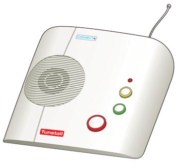
4 The Connect+ Front view Status Warning LED (Green/Yellow) Aerial Speaker Away/Feature Button (Yellow) Cancel Button (Green) Illuminated Alarm Button (Red) Back view Wall Mounting Points Hardwired Input/Output Volume Control and Ringer on/off Battery Compartment Cover Microphone Rubber Feet x 4 End view LINE Telephone Lead Socket AUX Accessory Socket Telephone Adaptor AC Mains Adaptor Socket 4

5 Installation advice IMPORTANT: If you have more than one phone, a modem, TV set top box or cordless telephone please read this section. Connect the Connect+ to the first telephone point in the house with all other extensions wired into the unit to ensure proper operation even when another telephone is in use or off hook (see below for more detailed instructions). All equipment requiring a link to the telephone line may be connected as follows: Extension phones/smart boxes/modems/tv set top boxes All telephones in the home may be plugged directly into the Connect+ using telephone adaptor b and the Connect+ socket labelled to enable the Connect+ to disconnect extension telephones when raising an alarm call. A multiple telephone adaptor may be required to connect more than one telephone (not supplied). Cordless phones Ensure that the main base/charger for the cordless phone which is used for all other handsets, is connected directly to the Connect+ as above. Broadband Please ensure a high quality filter is in use and the Connect+ is connected to the phone (analogue) socket on the filter. b 5


.")
. Switch the mains power to on.")
6 Quick start guide - New Zealand IMPORTANT: In order to function the Connect+ must be programmed correctly to a monitoring centre or personal responder. Please contact your local supplier if you are unsure whether your Connect+ has been programmed correctly. Step 1 - Connecting the leads and adaptors - Once the battery is inserted, please follow the steps below to plug the leads correctly into the Connect+. Step 1.1 Step Plug the telephone lead a into the Connect+ socket labelled LINE and the first/main telephone wall socket. a Step Plug the telephone adaptor b into the Connect+ socket labelled. Then plug all required telephones/equipment into the other end of the telephone adaptor using a multi socket extension if required (not supplied). See page 5 for more details. Step 1.2 b Step Plug the black mains adaptor c into the Connect+ socket labelled AC and then plug into the power point (mains power). Switch the mains power to on. Step Adjust speaker volume if required by pressing the volume control button d on the underside of Step 1.4 the Connect+ with a pen/pencil. After pressing in for a few seconds, the Connect+ will emit a tone, release the pen/pencil when the tone reaches the required volume. Step 1.3 d c 6
7 Step 2 - Testing Press the red alarm button on the Connect+ and ensure it successfully sends a call through to the monitoring centre or personal responder. Test the pendant by pressing its red button and ensuring it successfully sends a call. The pendant test should be done at various points around the property to ensure the radio range provides sufficient coverage for the user to raise an alarm call using their pendant. Step 3 - Adding pendants/telecare sensors For more information on adding pendants, please see page 14 of this guide. Contact your supplier if you require more information on how to programme telecare sensors to your Connect+. Step 4 - Ready to use Once successfully tested, the Connect+ is ready for use. Wall mounting Decide where you want to position the Connect+. Remember it should be within 2 metres of a mains power socket and the main telephone line socket. Then drill 2 holes 145mm apart, firmly attach screws (not supplied) leaving the screw heads protruding the surface and then locate the wall mounting points on the Connect+ with the screws. 7


8 Quick start guide - Australia IMPORTANT: In order to function the Connect+ must be programmed correctly to a monitoring centre or personal responder. Please contact your local supplier if you are unsure whether your Connect+ has been programmed correctly. Step 1 - Connecting the leads and adaptors Once the battery is inserted, please follow the steps below to plug the leads correctly into the Connect+. Step Plug the telephone lead a into the Connect+ socket labelled LINE and the first/main telephone wall socket directly or by using the adaptor supplied. Step 1.1 Option 1 Step 1.1 Option 2 b a a Step Plug the telephone directly into the Connect+ socket labelled. Alternatively plug the telephone into the telephone line adaptor b. Step 1.2 Step 1.2 b a 8 Step Plug the black mains adaptor c into the Connect+ socket labelled AC and then plug into the power point. Switch the mains power on. Step Adjust speaker volume if required by pressing the volume control button d on the underside of the Connect+ with a pen/pencil. After pressing for a few seconds, the Connect+ will emit a tone, release the pen/pencil when the tone reaches the required volume. Step 1.4 Step 1.3 c d
9 Step 2 - Testing Press the red alarm button on the Connect+ and ensure it successfully sends a call through to the monitoring centre or personal responder. Test the pendant by pressing its red button and ensure it successfully sends a call. The pendant test should be done at various points around the property to ensure the radio range provides sufficient coverage for the user to raise an alarm call using their pendant. Step 3 - Adding pendants/telecare sensors For more information on adding pendants, please see page 14 of this guide. Contact your supplier if you require more information on how to programme telecare sensors to your Connect+. Step 4 - Ready to use Once successfully tested, the Connect+ is ready for use. Wall mounting Decide where you want to position the Connect+. Remember it should be within 2 metres of a mains power socket and the main telephone line socket. Then drill 2 holes 145mm apart, firmly attach screws (not supplied) leaving the screw heads protruding the surface and then locate the wall mounting points on the Connect+ with the screws. 9
 and press the green cancel button.")


10 Using the Connect+ Making an alarm call Press the red button on the pendant or the red alarm button on the Connect+. Cancelling an alarm call If you need to cancel an alarm call wait 5 seconds (after the initial alarm button is pressed) and press the green cancel button. This in-built delay prevents false cancellation of an alarm call. Alarm calls made from a pendant can be cancelled immediately by pressing the green cancel button. Answering calls remotely via the pendant The pendant can be used to answer incoming telephone calls remotely by pressing the red button while the Connect+ or connected telephone is ringing. When pressed, the Connect+ will answer the call and you can speak to and hear the caller handsfree via the Connect+. To revert to handset mode, just pick up the handset of the connected telephone. Replacing the handset will end the call. To end a handsfree call, press the red button on the pendant again. Calls can also be answered at the Connect+ by pressing the green cancel button. 10


11 Status warnings Telephone line monitoring If the telephone line is faulty or becomes disconnected, the Connect+ will announce WARNING - the telephone line is disconnected after 1 minute and the green LED will flash. This warning will be repeated every 30 seconds until the telephone line becomes available again. To silence the warning, re-connect the telephone line. If the telephone line is connected and the warning continues, press the green cancel button. If the warning continues you should contact your telephone line supplier (e.g. Telstra) as the telephone line may be faulty. Power failure monitoring If a power failure occurs, the Connect+ will continue to work using its back-up battery, however, as a warning the red alarm button will flash once every 4 seconds (see section - the lights on the Connect+ indicate). The unit will also announce WARNING - there is no mains power. This warning is repeated every 5 minutes. To silence the warning reconnect the power lead. If the power failure lasts for more than 1 hour, during the next hour the unit will automatically call the monitoring centre. A call will be raised every 4 hours to the monitoring centre until the power is restored. The battery provides 40 hours of back up. 11
12 Status warnings The lights on the Connect+ indicate The lights on the Connect+ provide indications of its status based on the table below. Lights Red alarm button on Connect+ status Normal mode Red alarm button flashing Normal mode running on battery (1 every 4 seconds) (mains power off) Red alarm button flashing (1 every second) Alarm mode Green LED flashing (2 every second) Green LED on Green LED flashing (3 every second) Yellow LED on Yellow LED off Yellow LED flashing (1 every 4 seconds) Yellow LED flashing (2 every second) NO lights on Telephone line disconnected Telephone line in use Incoming ringing Feature button in away mode Feature button in home mode Low battery detected Intruder entry/exit time period Unit powered down (if power is on and connected then the unit may be faulty) The LED on the pendant indicates When pressed the red LED on the pendant will light up. This is to indicate that the button has been pressed. If the LED flashes when pressed this indicates that the pendant battery is low and should be replaced. You should contact your supplier as soon as possible in the event of low battery indication. Gem+ (Australia) LED Amie+ (New Zealand) 12
13 Features explained IMPORTANT: Inactivity monitoring and intruder monitoring require additional telecare sensors and may not be enabled on your Connect+. For information on these features or if you are unsure of how your away button has been programmed, please contact your supplier. Pendants The Amie+ and Gem+ pendants have the below features: AP Water resistant Up to 50m radio range (typical) Auto Low Battery* Greater than 100m line of sight Auto Presence** NOTE: *The pendant will automatically send a notification call via the Connect+ to the monitoring centre when its battery is low. **The pendant will automatically transmit a supervisory message to the Connect+ at 4 hourly intervals. The Connect+ will check that a transmission is received from each registered device and raise an alarm call to the Monitoring Centre if no transmissions are received within a pre-configured time period (generally 3 days). Reminder messages Up to six timed voice reminder messages can be remotely recorded on the Connect+ using a normal telephone. The messages can be set up to repeat at precise times either daily or once only, and can be modified or deleted at any time provided the person configuring the messages enters a security PIN (the default PIN is 1234). Configuring and recording reminder messages Step 1 - Use a telephone or mobile phone to call into the home phone. Step 2 - Answer the call by pressing the pendant or green cancel button. Step 3 - When answered using the pendant or green cancel button press 1 * on the telephone. Step 4 - You will then be prompted to key in your PIN (default 1234) Step 5 - The time currently held on the Connect+ s internal clock will then be confirmed. Step 6 - You will then be given 4 menu options. Firstly alter the time* if incorrect (menu option 3) and then follow the menu to configure and record each message. *NOTE: Times must be entered in 24 hour format e.g. 01 = 1am, 12 = midday, 13 = 1pm and 00 = midnight. Please contact your supplier for assistance. Listening to a reminder message When a reminder message is due, the Connect+ will announce Reminder and you must press the green cancel button to hear the message. 13
14 Features explained Personal responders The Connect+ can be used to make an alarm call to a personal responder (e.g. a relative or carer) before calling the monitoring centre. Please contact your monitoring centre if you wish to enable this feature. Inactivity monitoring The Connect+ can monitor movement around the home and send an alarm call to the monitoring centre if no movement is detected within a specific time period. To avoid false calls to the monitoring centre, inactivity monitoring should be de-activated when you leave your home. De-activate (away mode) - press the yellow away button (the yellow LED will turn on and the Connect+ announces Away ). Activate (home mode) - press the yellow away button (the yellow LED will turn off and the Connect+ announces Home ). Please contact your monitoring centre if you wish to enable this feature. Intruder monitoring The Connect+ has the ability to provide a simple to use intruder alarm facility, which will alert the personal responder on detection of an intruder. Arming (away mode) - when leaving your home you should turn on intruder monitoring by pressing the yellow away button once. The unit will announce Away, sound its exit tones and the yellow LED will turn on. You should leave your home and lock your door before the exit tones end (approximately 30 seconds). Disarming (home mode) - when entering your home the unit will sound its entry tones, you can easily switch off intruder monitoring during these entry tones by: Pressing the yellow away button once and then pressing your pendant straight away. Alternatively, an optional dedicated Arm/Disarm trigger is available When the intruder function has been disarmed, the unit will announce Home, the entry tones will stop and the yellow LED will turn off. Intruder functionality and inactivity monitoring If your Connect+ has been set up to monitor for inactivity as well as intruders, inactivity monitoring will automatically be suspended the moment intruder monitoring is armed. When intruder monitoring is disarmed, inactivity monitoring will automatically be restored. 14
15 Telecare Sensors What is Telecare? Telecare consists of various sensors placed around the home linked to the Connect+. The sensors provide greater reassurance and protection by monitoring for environmental risks such as flooding and fire as well as personal risks such as falling. Upon detection of a dangerous situation the sensors automatically generate an alarm to the Connect+ which then alerts a personal responder or the monitoring centre where a highly trained operator can quickly deal with the issue and take the most appropriate action. Programming a telecare sensor to the Connect+ Telecare sensors with plug and play functionality can be programmed to the Connect+ using the following steps: Step 1 - Step 2 - Step 3 - Step 4 - Step 5 - Press and hold down the green cancel button until it beeps (approx 5 seconds). The Connect+ announces Programming mode and the red alarm button flashes slowly. Press and hold down the green cancel button again until it beeps (approx 3 seconds). Release the cancel button, the red alarm button flashes rapidly. Activate the sensor/trigger, the Connect+ will beep to confirm acceptance. Press and release the green cancel button. The Connect+ will beep (programming mode exited). Test the sensor/trigger by activating it and ensuring it raises an alarm call. If you would like to know which telecare sensors are currently available, please contact your supplier. 15
16 Help and advice False alarms If you accidentally raise a false alarm, please do not worry as your monitoring centre is always happy to hear from you and the raising of the alarm acts as a useful test of your Connect+. Troubleshooting If your Connect+ does not work: Ensure the telephone lead is plugged into the main telephone socket - see page 6 (New Zealand) or page 8 (Australia) Ensure that the mains adaptor is plugged into the unit and a wall socket - see page 6 (New Zealand) or page 8 (Australia) Ensure that the power supply is switched on (the red alarm button should be illuminated). If the Connect+ LED is on or flashing, please see the status warning section on page 11. Cleaning Dust the Connect+ with a soft cloth which can be moistened with a gentle detergent if required. Ensure that no moisture goes through the speaker grill. Moisture Don t position your Connect+ where it may come into contact with water or moisture. Pendants are water resistent (to IP67 standard) up to 1m. They can be worn in the shower however wearing them in the bath should be avoided where possible. Battery information Connect+ The Connect+ contains a Nickel Metal Hydride back-up battery that is user changeable and recharges itself when plugged into the mains. It is recommended that this battery is replaced after 5 years. The battery provides 40 hours of standby operation with 5 alarm sequences at the end as per AS4607. Pendants Pendants contain a 3V Lithium battery that is not user changeable. The battery has an expected life of 5 years (20,000 operations). Please contact your supplier for replacement pendants. 16 All batteries should be disposed of in accordance with the latest legislation.
17 Taking care of your alarm Dos Keep the Connect+ connected to the mains power at all times. Connect the Connect+ to the first telephone point in the house with all other extensions wired into the unit to ensure proper operation even when another telephone is in use or off hook. Contact your supplier as soon as possible after the LED on your pendant indicates a low battery. Don ts Expose the Connect+ alarm unit to water or other liquids. Connect cables other than those supplied with the Connect+. Place the Connect+ next to something that makes lots of noise, such as next to a television, radio or washing machine. Place the Connect+ close to a heat source e.g. cooker or large metal objects e.g. microwave. Declaration Australia Clause Declaration required The CE will not cause harm or damage to a Telecommunications Network or Facility if any of the following events, or consequential event occurs: (a) failure of any mechanical or electrical component in the CE; or (b) failure of any power supplies resulting in total or partial loss of power to the CE (c) Discharge or partial discharge of any battery supply associated with the CE (d) incorrect manual operation of the CE New Zealand Clause Declaration required (3) " This equipment shall not be set up to make emergency calls to the Telecom "111" Emergency Service" 6.3 (3) " This equipment may not provide for the effective hand-over of a call to another device connected to the same line" (3) " Under power failure conditions, this telephone may not operate. Please ensure that a separate telephone, not dependent on local power, is available for emergency use" (b) " This equipment shall not be set up to make automatic calls to the Telecom '111' Emergency Service" 17
18 18 Notes
19 Notes 19
20 Technical Details Weight: 670 g Dimensions: Mains power: Stand-by battery: Back-up time: Radio frequency: 157 x 189 x 49mm (WxLxD) 240v AC 50Hz 2000mAhr capacity (continually internally charged) 40 hours of stand-by operation with 5 emergency call sequences during this period as per AS4607 (minimum expected at date of purchase and when fully charged) 312MHz External connections: Plug top transformer with 3m cable New Zealand - 3m telephone line cord with type BS6312 plug Australia - 3m telephone line cord with an RJ connector and series 610 adaptor Environmental Temperature: Operating temperature (to perform to full specification) = 0 C to 45 C, storage = -10 C to 50 C Humidity: Operating relative humidity (non condensing to perform to full specification) = 0 to 80%, storage relative humidity (non condensing) = 0 to 93% Standards EMC: AS/NZS CISPR 22:2006 Safety: AS/NZS :2003 Telecoms: PTC200 : Issue 2, including amendment 1, Nov 1997 (PTC212/05/001) ACIF S002:2005 ACIF S004:2006 Radio: AS/NZS 4268:2003 Personal Response Systems AS4607 Design, Manufacture, Installation and Service: ISO9001:2000 MEPS: AS/NZS Declaration of Conformity We, Tunstall declare that this social alarm equipment is in compliance with the essential requirements and other relevant provisions of the R&TTE Directive 1999/5/EC. Tunstall Healthcare Asia Pacific, 1/56 Lavarack Avenue, Eagle Farm, QLD 4009 Australia Mail: Locked Bag 1, 985 Kingsford Smith Drive, Eagle Farm, QLD 4009 Australia Toll Free: Tel: Fax: Tunstall NZ Healthcare Trust, 306 Cameron Road, Tauranga, 3110 New Zealand Mail: PO Box 13153, Tauranga, 3141 New Zealand Tel: Fax: Our policy of continual development means that product specification and appearance may change without notice. Tunstall does not accept responsibility for any errors and omissions contained within this document Tunstall Group Ltd. TUNSTALL is a registered trademark. A member of the Tunstall Healthcare Group Limited. Tunstall Healthcare (UK) Ltd, Whitley Lodge, Whitley Bridge, Yorkshire DN14 0HR Tel: Fax: enquiries@tunstall.co.uk 20
Tunstall Vi+ User Guide
 Tunstall Vi+ User Guide Your Tunstall Vi home unit The Tunstall Vi home unit is connected to the mains power supply and your telephone line. It enables you to generate a call for help when and if you need
Your Lifeline Vi+ home unit. Your MyAmie pendant
 User Guide Your Lifeline Vi+ home unit The Lifeline Vi+ home unit is connected to the mains power supply and your telephone line. It enables you to generate a call for help when you need it by immediately
Lifeline 400 user guide q6 18/2/04 10:56 am Page 2. Lifeline 400. installation and user guide. Part Number D B
 Lifeline 400 user guide q6 18/2/04 10:56 am Page 2 Lifeline 400 installation and user guide Part Number D3707103B Lifeline 400 user guide q6 18/2/04 10:56 am Page 3 Contents Your Lifeline 400 P3-4 What
D C. Caresse GSM Installation and Programming Guide
 D5107148C Caresse GSM Installation and Programming Guide Contents What s in the box?... 3 The home unit... 4 Front view... 4 Back view... 4 End view... 4 What is the Caresse GSM?... 5 How to install the
Smart Hub. User & Installation Guide
 Smart Hub User & Installation Guide Your Tunstall Smart Hub The Tunstall Smart Hub is connected to the mains power supply and has a builtin battery in case of mains power failure. The Smart Hub connects
Quick set-up guide. [Simple plug and play system]
![Quick set-up guide. [Simple plug and play system]](/thumbs/74/70692342.jpg "Quick set-up guide. [Simple plug and play system]") Quick set-up guide [Simple plug and play system] Life is a journey Welcome to your Lifeline at Home service, providing constant reassurance that help is at hand 24 hours a day. Once installed simply press
Quick set-up guide [Simple plug and play system] Life is a journey Welcome to your Lifeline at Home service, providing constant reassurance that help is at hand 24 hours a day. Once installed simply press
The following equipment is included in your Tunstall Home box t :
 Quick set-up guide Life is a journey Welcome to your Tunstall Home service, providing constant reassurance that help is at hand 24 hours a day. Once installed simply press the red button on the Lifeline
communicall connect solutions sheet What is Communicall Connect? Who is it for? What does it consist of?
 solutions sheet communicall connect What is Communicall Connect? Communicall Connect is Tunstall s most advanced grouped housing communication system. Its innovative design builds upon the success of Tunstall
USER & INSTALLATION GUIDE
 Reach Plus At Home Alarm Unit Touch Personal Pendant USER & INSTALLATION GUIDE www.tynetec.co.uk SECTION 1 USER INSTRUCTIONS Section Topic Page 1.1 Important Information 3 1.2 Unpacking the Reach Plus
MEDICAL ALERT SETUP GUIDE
 MEDICAL ALERT SETUP GUIDE GETTING STARTED STARTED You have made a great decision to protect yourself with Medical Alert! Be sure to wear your wrist button or neck button everyday to stay protected all
Lifeline Vi Clever, not complicated
 Solution Sheet Clever, not complicated The is Tunstall s sixth generation home unit and sets the benchmark in the development of telecare solutions. It s the most technically advanced, flexible and simple
ConnectMe. Tunstall Vi+ Installation and Programming Guide
 ConnectMe Tunstall Vi+ Installation and Programming Guide Contents Installation Guide... 4 What s in the box... 4 Your home unit... 6 For your safety - Installation advice... 7 Quick start guide... 8 Table
D B Version 9.9. Lifeline Vi/Vi+ Installation and Programming Guide
 D5307013B Version 9.9 Lifeline Vi/Vi+ Installation and Programming Guide Contents Installation Guide... 4 What s in the box... 4 Your home unit... 5 For your safety - Installation advice... 6 Quick start
TABLE OF CONTENTS. Your Northwood Intouch Unit (Diagram)...1. How to use your Emergency Response System... 2
...1. How to use your Emergency Response System... 2") TABLE OF CONTENTS Your Northwood Intouch Unit (Diagram)...1 How to use your Emergency Response System... 2 Important Information about your Personal Help Button... 3 Answering an Incoming Call Handsfree...4
TABLE OF CONTENTS Your Northwood Intouch Unit (Diagram)...1 How to use your Emergency Response System... 2 Important Information about your Personal Help Button... 3 Answering an Incoming Call Handsfree...4
Tunstall Vi+ Installation and Programming Guide
 Tunstall Vi+ Installation and Programming Guide 1 Contents Installation Guide... 4 What s in the box?... 4 The Home Console Unit... 5 Installation Advice... 6 Quick start guide... 7 How to install... 7
Programming the Vi+ using a Series Telephone. Tunstall Vi+
 Tunstall Vi+ Programming the Vi+ using a SeriesTelephone Your Vi+ Page 2 Ver 1 4/24/2015 Programming a telecare sensor to the Vi+ Telecare sensors with plug and play functionality can be programmed to
Life Changing, Life Saving. The Vibby. User and Installation Guide
 Life Changing, Life Saving The Vibby User and Installation Guide Contents Introduction Getting started Alarm modes Types of falls Simulating a fall Automatic alarm cancellation Manual alarm cancellation
WIRELESS ALARM SYSTEM WITH TELEPHONE AUTO DIALER
 BAT.LOW AC WIRELESS ALARM SYSTEM WITH TELEPHONE AUTO DIALER THE SYSTEM THAT CALLS YOU! Our WIRELESS ALARM SYSTEM WITH TELEPHONE AUTO DIALER is designed to allow you to create your own security system.
USER & INSTALLATION GUIDE
 Reach At Home Alarm Unit Touch Personal Pendant USER & INSTALLATION GUIDE www.tynetec.co.uk SECTION 1 USER INSTRUCTIONS Section Topic Page 1.1 Important Information 3 1.2 Unpacking the Reach At Home Alarm
MK9 series CarePhone. Installers Mauual
 MK9 series CarePhone Installers Mauual 1 Please ensure that the last thing you do before leaving a User with an alarm is to make a test call through to the Monitoring Centre and speak to the Operator.
NON-MONITORED EMERGENCY CALL SYSTEMS
 NON-MONITORED EMERGENCY CALL SYSTEMS A non-monitored emergency call system includes a pendant and a control box or phone which is connected to the telephone network (via landline or mobile network). When
Smart Hub. Connecting people, connected care. What is it? Who is it for? How does it work?
 Smart Hub Connecting people, connected care What is it? The Lifeline Smart Hub is a complete Connected Care monitoring and alarm system for the home. It uses future proof, smart technology to connect service
A1UL PERS. Personal Emergency Response System. For Technical Support Please Contact Your Service Provider Or Distributor
 A1UL PERS Personal Emergency Response System TABLE OF CONTENTS 1. READ THIS FIRST... 1 2. SYSTEM OVERVIEW.. 1 3. COMPONENTS 2 4. UNIT OPERATION! Standby Mode.. 3! Emergency Activation. 3! Answering Incoming
Voice Board. Installation and Programming Guide. Runner 4/8,PowerWave 4/8/16 &, Elite64. Add-on Board For Storing Recorded Voice Messages
 ELECTRONIC ENGINEERING LTD. Voice Board Runner 4/8,PowerWave 4/8/16 &, Elite64 Add-on Board For Storing Recorded Voice Messages And listen-in. Installation and Programming Guide. P/N 7101372 Rev. C V.K
Elite 64 Version 64 Zone Controller Arrowhead Alarm Products Ltd. Operating Guide. Proudly Designed and Manufactured in New Zealand
 2 Elite 64 Version 64 Zone Controller Arrowhead Alarm Products Ltd Operating Guide Proudly Designed and Manufactured in New Zealand 1 CONTENTS Page No. INTRODUCTION 3 About your Alarm 3 OPERATING YOUR
169MHz Telecare Devices Touch Personal Pendant
 169MHz Telecare Devices Touch Personal Pendant What is the Touch Pendant used for? Compatible with Reach at home alarms, Advent xt warden call, Altec Response and Touchsafe Pro Nursecall systems Fully
Elite 16D Version 16 Zone Controller Arrowhead Alarm Products Ltd. Operating Guide. Proudly Designed and Manufactured in New Zealand
 6 Elite 16D Version 16 Zone Controller Arrowhead Alarm Products Ltd Operating Guide 1 Proudly Designed and Manufactured in New Zealand CONTENTS Page No. INTRODUCTION 3 About your Alarm 3 OPERATING YOUR
Vibby. Installation Guide. t: f: e: w: uk.tunstall.com Version: V3.9
 Vibby Installation Guide t: 01977 661234 f: 01977 660562 e: enquiries@tunstall.com w: uk.tunstall.com Version: V3.9 Contents 1. Introduction... 3 Exiting from storage mode...4 2. Getting Started... 5 Entering
Thank you for choosing Ideal Security s Home Security System with Telephone Dialer.
 SK618 WIRELESS ALARM SYSTEM WITH AUTO DIALER OWNER'S MANUAL Thank you for choosing Ideal Security s Home Security System with Telephone Dialer. If at any time during your installation you have any questions
DESTINY 6100 SERIES SECURITY SYSTEM OWNER S MANUAL V1 12/01
 DESTINY 6100 SERIES SECURITY SYSTEM OWNER S MANUAL 800-6006V1 12/01 System Overview General Information Control Panel Detection Devices You have made a wise decision to protect your family and property
TYDOM 315. * _Rev.2* GSM domotics transmitter. 1. Presentation
 TYDOM 5 GSM domotics transmitter ) Présentation. Presentation Delta Dore hereby declares that the equipment complies with the essential requirements and other relevant provisions of the R&TTE Directive
DESTINY OWNER S MANUAL
 DESTINY OWNER S MANUAL DESTINY You have made a wise decision to protect your family and property with the DESTINY Security System. The DESTINY has been designed to provide you with a maximum level of security
Solution Ultima Series Operators Manual ISSUE 1.00
 Solution Ultima Series Operators Manual ISSUE 1.00 Solution Ultima Series Operators Manual Copyright 1998 by, SYDNEY, AUSTRALIA Document Part Number MA488O DOCUMENT ISSUE 1.00 Printed 16 February 1999
TYNETEC. Telecare for independent living THE GLOBAL SPECIALIST IN ELECTRICAL AND DIGITAL BUILDING INFRASTRUCTURES MOBILE NETWORK
 Telecare for independent living 3G MOBILE NETWORK THE GLOBAL SPECIALIST IN ELECTRICAL AND DIGITAL BUILDING INFRASTRUCTURES Enabling people to live independently for longer in their own home The Reach Plus
l 02-April-2010 For INSTANT CARE
 l 02-April-2010 For INSTANT CARE Table of Contents 1. Application Overview 1 1.1. Identifying The Parts 1 1.2. The Power Supply 3 1.3. Line Capture 3 1.4. Line Failure Detection 4 1.5. How to install the
Destiny Destiny Owners Manual
 Destiny 4100 Destiny 4100 Owners Manual TABLE OF CONTENTS INTRODUCTION Control Panel...3 Detection Devices...3 Telephone Keypads...3 GLOSSARY... 4-5 LOCAL PHONE ACCESS Using Your Telephones As Keypads...6
CC880/LP880, SC8016. Operators Guide Solution-16, Solution-16 Safecom
 CC880/LP880, SC8016 EN Operators Guide Solution-16, Solution-16 Safecom CC880/LP880, SC8016 Operators Guide EN 2 Copyright Notice Unless otherwise indicated, this publication is the copyright of Bosch
Contents. Glossary
 Contents Glossary ------------------------------------------------------------------------------------------------------ 6 1. Introduction to the IDS 1632 -------------------------------------------------------------
STEP-HEAR Activator (SH-220)
") E n g lish STEP-HEAR Activator (SH-220) User Guide NAVIGATION AND INFORMATION SYSTEM FOR VISUALLY IMPAIRED AND BLIND PEOPLE CONTENTS CONTENTS 2 INTRODUCTION 3 Unpacking the Activator 4 DESCRIPTION 5 Activator
E n g lish STEP-HEAR Activator (SH-220) User Guide NAVIGATION AND INFORMATION SYSTEM FOR VISUALLY IMPAIRED AND BLIND PEOPLE CONTENTS CONTENTS 2 INTRODUCTION 3 Unpacking the Activator 4 DESCRIPTION 5 Activator
Rev C May GE Interlogix. Part No: R. CareGard. User Guide
 g 466-1936 Rev C May 2003 GE Interlogix www.ge-interlogix.com Part No: 60-883-95R CareGard User Guide FCC Notices FCC Part 15 Information to the User Changes or modifications not expressly approved by
Universal Sensor. Installation Guide. t: f: e: w: uk.tunstall.com Version: V2.97 (421V0R1.
 Universal Sensor Installation Guide t: 01977 661234 f: 01977 660562 e: enquiries@tunstall.com w: uk.tunstall.com Version: V2.97 (421V0R1.18) Contents 1. Features and Introduction... 3 Your Universal Sensor...3
MOBILE CALL GSM Alarm System User s Manual
 MOBILE CALL GSM Alarm System User s Manual Profile For a better understanding of this product, please read this user manual thoroughly before using it. Contents Function Introduction (3) Alarm Host Diagram
SK642 THE TELEPHONE DIALER REQUIRES A LAND TELEPHONE LINE TO MAKE OUTGOING CALLS AND ELECTRICITY.
 SK642 WIRELESS WATER ALARM SYSTEM WITH AUTO DIALER OWNER'S MANUAL AND SET UP INSTRUCTIONS. Thank you for choosing Ideal Security s Wireless Water Alarm with Telephone Dialer. Please read through complete
USER GUIDE HARDWIRED CONTROL PANELS
 USER GUIDE HARDWIRED CONTROL PANELS Scantronic Contents 1. Introduction... 3 The Alarm System... 3 The Keypads... 3 The 725r Remote Setting Device... 6 About This Guide... 6 2. Everyday Operation... 7
Telecare User Guidance
 Summary Telecare User Guidance This guidance describes; what Telecare is and how it may assist you, how you can apply for Telecare, if you are eligible and how much it may cost, how it is installed, how
Thank you for choosing Ideal Security s Home Security System with Telephone Dialer.
 SK618 WIRELESS ALARM SYSTEM WITH AUTO DIALER OWNER'S MANUAL Thank you for choosing Ideal Security s Home Security System with Telephone Dialer. If at any time during your installation you have any questions
Preface. Thank you for purchasing our GSM Security Alarm System ( The System )! The System will keep your home and property safe around the clock.
! The System will keep your home and property safe around the clock.") Preface Thank you for purchasing our GSM Security Alarm System ( The System )! The System will keep your home and property safe around the clock. The GSM Security Alarm ( The Alarm ) adopts the most advanced
Preface Thank you for purchasing our GSM Security Alarm System ( The System )! The System will keep your home and property safe around the clock. The GSM Security Alarm ( The Alarm ) adopts the most advanced
PERS-3600 PERSONAL EMERGENCY REPORTING SYSTEM INSTALLATION & OPERATION INSTRUCTIONS
 PERS-600 PERSONAL EMERGENCY REPORTING SYSTEM BY BY INSTALLATION & OPERATION INSTRUCTIONS (760) 8-7000 USA & Canada (800) -587 & (800) 9-0 Toll Free FAX (800) 68-0 www.linearcorp.com CONTENTS CONTROL AREA
ICP-CC488 ICP-CC488 EN. Control Panel. User s Guide
 ICP-CC488 EN User s Guide ICP-CC488 Control Panel ICP-CC488 User's Guide Notices EN 2 Copyright Notice Unless otherwise indicated, this publication is the copyright of Bosch Security Systems, Inc. ( Bosch
CORPORATION PTY LTD MEDI-LINK
 division of NESS CORPORTION PTY LTD MEDI-LINK USER MNUL Medi-Link User Manual V1.08 division of NESS CORPORTION PTY LTD Copyright SmartLink International October 2011 Unit 4/56 Norcal Rd, Nunawading VIC
169MHz Telecare Devices Companion Epilepsy Monitor
 169MHz Telecare Devices Companion Epilepsy Monitor Compatible with Reach at home alarms, Advent xt warden call, Altec Response and Touchsafe Pro Nursecall systems Detects nocturnal tonic clonic seizures
Alarm System SECURE AS 302
 Alarm System SECURE AS 302 Operating Manual SECURE Light app now available! Table of Contents Before You Start.................................. 4 User Information....................................4
MEDI-LINK USER MANUAL
 MEDI-LINK USER MNUL Medi-Link User Manual Rev1.2 division of NESS CORPORTION PTY LTD November 2015 Unit 4/56 Norcal Rd, Nunawading VIC 3131 ustralia Tel: +61 3 9875 6400 Facsimile: +61 3 9875 6422 Email:
ICP-CC408 ICP-CC408 EN. Control Panel. User s Guide
 ICP-CC408 EN User s Guide ICP-CC408 Control Panel ICP-CC408 User's Guide Notices EN 2 Copyright Notice Unless otherwise indicated, this publication is the copyright of Bosch Security Systems, Inc, ( Bosch
Wireless Keypads LKP(E)S8M Series
S8M Series") Wireless Keypads LKP(E)S8M Series User manual Contents Congratulations on your purchase of this Honeywell wireless keypad. To make the best out of your equipment we advise you to read this manual carefully.
Wireless Keypads LKP(E)S8M Series User manual Contents Congratulations on your purchase of this Honeywell wireless keypad. To make the best out of your equipment we advise you to read this manual carefully.
To activate using remote control: press [ ] key once. To activate using keyboard: on panel keyboard [ ] keys once.
![To activate using remote control: press [ ] key once. To activate using keyboard: on panel keyboard [ ] keys once.](/thumbs/93/113878877.jpg "To activate using remote control: press [ ] key once. To activate using keyboard: on panel keyboard [ ] keys once.") Table of Content 1.1General Description----------------------------------------------------------------------2 2.2System Setup-----------------------------------------------------------------------------3
Table of Content 1.1General Description----------------------------------------------------------------------2 2.2System Setup-----------------------------------------------------------------------------3
MEDI-CALL UNIT INSTALLATION MANUAL. Medi-Call V2.0 - V2.7 Installation Manual
 MEDI-CALL UNIT INSTALLATION MANUAL Medi-Call V2.0 - V2.7 Installation Manual Copyright SmartLink International Pty Ltd February 2006 475 Nepean Highway, Brighton VIC 3186 Australia Telephone: +61 3 9596
User instructions EasyAlarm CONTROL
 LEITRONIC AG Swiss Security Systems TELEMONITORING / TELECONTROLLING SYSTEM User instructions EasyAlarm CONTROL Interface-Modul Potential free relay switch: 10..230V AC or DC AC-switch: max. 2A / 230V
1. Introduction. 2. Product overview
 1. Introduction The AG400011 GSM Alarm panel is a control panel that is compatible with other H-net security devices from Everspring, such as wireless sensors, remote keyfobs, tags, and keypad. With this
Profile. For a better understanding of this product, please read this user manual thoroughly before using it.
 Intelligent GSM Auto-Dial Alarm System User s Manual Profile For a better understanding of this product, please read this user manual thoroughly before using it. Contents Function Introduction (3) Alarm
SA 2650 Kit User Manual
 SA 2650 Kit User Manual Table of Contents 1. System Installation Planning 1 2. Device Introduction 3 3. Getting Started 6 4. System Default Setting 10 5. Connect2Home Application 11 6. System Information
2-ZONE EASYFIT INTRUDER ALARM
 EXTERNAL SIREN MM05 PIR SENSOR DOOR CONTACTS -ZONE EASYFIT INTRUDER ALARM INSTALLATION & OPERATING INSTRUCTIONS IMPORTANT: PLEASE READ THESE INSTRUCTIONS CAREFULLY BEFORE ATTEMPTING TO INSTALL THIS ALARM
Control Panel. Operators Manual TO SUIT AS216 KEYPAD. AS216-OM-6.2. Advanced Digital Controls
 Control Panel Operators Manual TO SUIT AS216 KEYPAD AS216-OM-6.2 Ultra-16 Control Panel AS216 OPERATORS MANUAL Copyright 2002 by NZ Ltd Auckland, New Zealand Document Part Number: This document is provided
IDS S E C U R I T Y IDS816. User Manual MANUAL NO B ISSUED DEC 2004 VERSION 2.00
 INHEP DIGITAL IDS S E C U R I T Y IDS816 User Manual MANUAL NO. 700-283-01 B ISSUED DEC 2004 VERSION 2.00 Contents 1. Introduction to the IDS816... 4 2. Understanding the Keypad Indicators... 4 3. Programmable
MEDI-MINDER USER MANUAL
 MEDI-MINDER USER MANUAL TABLE OF CONTENTS TABLE OF CONTENTS... 1 INTRODUCTION... 1 SMARTLINK FEATURES... 2 USING SMARTLINK... 3 SPECIAL FUNCTIONS... 5 DISPLAYS AND WARNINGS... 6 SPECIFICATIONS... 7 INTRODUCTION
V1.0. Smart Home Alarm System. User Manual. APP download via QR Code scanning. Please read the manual carefully before using.
 V1.0 Smart Home Alarm System User Manual APP download via QR Code scanning Please read the manual carefully before using. Content FUNCTION PROFILE 2 THE SCHEMATIC GRAPH OF HOST 3 PROCESS OF BOOTING 6 OPERATION
IDS S E C U R I T Y IDS816. User Manual. MANUAL NO A ISSUED November 2004 VERSION 1.00
 INHEP DIGITAL IDS S E C U R I T Y IDS816 User Manual MANUAL NO. 700-283-02A ISSUED November 2004 VERSION 1.00 Contents 1. Introduction to the IDS816... 4 2. Understanding the Keypad Indicators... 4 3.
The Windcrest Remote Alarm for Passenger and Goods Lifts with Optional BS EN81-28 & BS EN81-70
 The Windcrest Remote Alarm for Passenger and Goods Lifts with Optional BS EN81-28 & BS EN81-70 1. Identify the Equipment and carry out a Risk Assessment before installation AD1000EN- 1R Main Unit EN1 Speaker
ERS-3600B. PERS-3600B Personal Emergency Reporting System
 PERS-3600B Personal Emergency Reporting System ERS-3600B A Complete Emergency System For Comprehensive Care The Linear PERS-3600B includes a built-in speakerphone and reminder message capability, providing
Watchguard WGAP864 User Manual
 Watchguard WGAP864 User Manual v1.0 Issued September 2016 1 2 Table of Contents Glossary... 5 1. Introduction to your Watchguard WGAP864... 6 2. Before Operating your Alarm System... 6 3. Understanding
Operators Guide ENGENIUS EP800 CORDLESS TELEPHONE
 Advent xt Warden Call System Operators Guide ENGENIUS EP800 CORDLESS TELEPHONE Tynetec operates a policy of continual product improvement and reserves the right to modify the specification of its products.
Solution Ultima 862 Operators Manual ISSUE 1.10
 Solution Ultima 862 Operators Manual ISSUE 1.10 Solution Ultima 862 Operators Manual Copyright 2001 by, SYDNEY, AUSTRALIA Document Part Number MA486O DOCUMENT ISSUE 1.10 Printed 24 April 2001 This documentation
2-ZONE EASYFIT INTRUDER ALARM
 SIREN PIR SENSORS MM084 MM44 MAINS ADAPTOR DOOR CONTACTS Please note: Before you start to install this Micromark Alarm, we advise that you should take adequate safety precautions when using power tools
Solution 844 Operators Manual ISSUE 1.10
 Solution 844 Operators Manual ISSUE 1.10 Solution 844 Operators Manual Copyright 2001 by, SYDNEY, AUSTRALIA Document Part Number MA406O DOCUMENT ISSUE 1.10 Printed 24 April 2001 This documentation is provided
QUICKFIT INSTALL HOOK-UP SHEET FOR ESL KIT REV 1.17 OP
 QUICKFIT INSTALL HOOK-UP SHEET FOR ESL KIT REV 1.17 OP PROGRAMMING STARTS Entering Installer mode If you want to get into program mode press followed by your installer code, default set to 000000
169MHz Telecare Devices Sensor Controller
 169MHz Telecare Devices Sensor Controller Compatible with Reach at home alarms, Advent xt warden call, Altec Response and Touchsafe Pro Nursecall systems Can be used for bed or chair occupancy monitoring
Contents. Glossary Introduction to the IDS Notes Understanding the Keypad Indicators Operation of the Keypad...
 2 Contents Glossary...7 1. Introduction to the IDS805...8 1.1 Notes...8 2. Understanding the Keypad Indicators...8 3. Operation of the Keypad...9 4. System Information...10 4.1 Programmed Functions...10
Digiplex LED Keypads. User s Manual
 Digiplex LED Keypads User s Manual TABLE OF CONTENTS INTRODUCTION... 6 1.1 Legend...6 BASIC OPERATION... 7 2.1 Auditory Feedback (Beep Tones)...8 2.2 Keypad Indicator Lights...8 2.3 LED Keypads...8 2.4
Premium 8 Zone Wireless Alarm Kit
 Premium 8 Zone Wireless Alarm Kit INTRODUCTION The wireless alarm system is designed to protect your home. It is a simple to use, easy to install unit. No special tools or training are required, all fixings
Using Your. Security System With LED Keypad S5030, S5031, S5032
 Using Your Security System With LED Keypad S5030, S5031, S5032 Contents 1 Overview Your Security System... 1 How Your Security System Works... 2 Your System's Programming... 3 Getting Used to Your System...
CONTENTS. (User s Manual)
") CONTENTS (User s Manual) 1. Foreword & Main Features & Brief introduction of the Product 2. Understanding of Alarm Host 3. Specifications 4. Type and definition of Defense Line 5. Programming the alarm
CONTENTS (User s Manual) 1. Foreword & Main Features & Brief introduction of the Product 2. Understanding of Alarm Host 3. Specifications 4. Type and definition of Defense Line 5. Programming the alarm
GSM Alarm System. User s Manual. Profile. MOBILE CALL GSM Alarm System
 MOBILE CALL GSM Alarm System GSM Alarm System System disarmed 11/26/2013 User s Manual Profile For a better understanding of this product, please read this user manual thoroughly before using it. CONTENTS
MXD3G User Manual Revision 0 July 29, 2013
 MXD3G User Manual Revision 0 July 29, 2013 Manufactured by Mytrex, Inc. 10321 South Beckstead Lane South Jordan, UT 84095 (801) 571-4121, Fax (801) 571-4606 Toll Free (800) 688-9576, Fax (877) 571-4606
IDS816 User Manual H Issued January 2009
 1 Contents Glossary-------------------------------------------------------------------------------------------------------------------6 1. Introduction to the IDS 816---------------------------------------------------------------------------7
IDS S E C U R I T Y IDS816. User Manual MANUAL NO C ISSUED APRIL 2005 VERSION 2.00
 INHEP DIGITAL IDS S E C U R I T Y IDS816 User Manual MANUAL NO. 700-283-01C ISSUED APRIL 2005 VERSION 2.00 Contents 1. Introduction to the IDS816... 4 2. Understanding the Keypad Indicators... 4 3. Programmable
NESS 5000 SERIES DIALLER
 NESS 5000 SERIES DIALLER INSTALLATION MANUAL This manual is designed to provide the installation instructions on the NESS SECURITY PRODUCT'S 5000 SERIES Dialler. For complete details on the warranty or
Security System. User Guide for the LED Command Center
 Security System User Guide for the LED Command Center National Security Systems Inc (800)457-1999 MY SECURITY COMPANY IS: CALL BEFORE TEST: THIS SECURITY SYSTEM IS CONNECTED TO TELEPHONE NUMBER: THE SECURITY
169MHz Telecare Devices Deaf Smoke Alarm Kit
 169MHz Telecare Devices Deaf Smoke Alarm Kit Compatible with Reach at home alarms, Advent xt warden call, Altec Response and Touchsafe Pro Nursecall systems Optical smoke detector with integral sounder
HARDWIRED CONTROL PANELS
 USER GUIDE 9651 HARDWIRED CONTROL PANELS Contents 1. Introduction...3 The Alarm System...3 The Keypad...3 About This Guide...5 2. Everyday Operation...6 How Do I Know if the System is Working?...6 Setting
Version 1.03 January-2002 USER S MANUAL
 Version 1.03 January-2002 1 USER S MANUAL 2 Version 1.03 January-2002 System Details CUSTOMER:...... PHONE:... FAX:... INSTALLED BY:...... PHONE:... FAX:... MAINTENANCE & SERVICE:...... PHONE:... FAX:...
Quick Installation Manual LED Touch Keypad Autodial Wireless Alarm System
 Quick Installation Manual LED Touch Keypad Autodial Wireless Alarm System By shield4u http:// (Version 20110816) A. Alarm Understanding Away Disarm Home Emergency Function Signal Interpretation Buzzer
The most user friendly Security Alarm System L S Section 1 Overview of System Section 2 Planning your Installation
 The most user friendly Contents Section 1 Overview of System 1.1 Kit Contents 1.2 Tools Required 1.3 System Features Security Alarm System L S 4 0 0 Section 2 Planning your Installation 2.1 Location of
System. For a better understanding of this product, please read this user manual thoroughly before using it.
 GSM Alarm System User s Manual For a better understanding of this product, please read this user manual thoroughly before using it. Chapter 1. Features Chapter 2. Control Panel Introduction Chapter 3.
Independent Living without Leaving Home. Personal Emergency Reporting Systems from Linear
 Independent Living without Leaving Home Personal Emergency Reporting Systems from Linear Connected and Reliable You can live in your own home independently, safe, secure and free from worry. Assistance
ADE Gen4. Speech Dialler Engineering Information. Description. Features
 ADE Gen4 Speech Dialler Engineering Information Description The Informa is a Speech Dialler for use with intruder alarm systems. When the control panel recognises an alarm it triggers the Informa. The
Elite S Version 8-16 Zone Controller Arrowhead Alarm Products Ltd. Operating Guide. Proudly Designed and Manufactured in New Zealand
 9 Elite S Version 8-16 Zone Controller Arrowhead Alarm Products Ltd Operating Guide Proudly Designed and Manufactured in New Zealand 1 CONTENTS Page No. INTRODUCTION About your Alarm 3 3 OPERATING YOUR
Wolf Guard Touch Keypad GSM Wireless alarm system User s Manual
 Wolf Guard Touch Keypad GSM Wireless alarm system User s Manual Page 1 Warning Do not remove the front or back cover of the unit and keep it intact. There are no parts inside this unit that can be repaired
Quick Reference Guide
 WARNING This manual contains information on limitations regarding product use and function and information on the limitations as to liability of the manufacturer. The entire manual should be carefully
Auto Dialer. Manual E-921APQ E-921GPQ
 Troubleshooting: Auto dialer will not arm/disarm Auto dialer will not dial out Unit doesn t respond to a call-back Difficulty in activating room monitor by telephone remote control Make sure that you have
L900 series USER MANUAL
 INTRODUCTION The BLUGUARD Control Panel is designed for simple operation yet provides the maximum protection for you. Please read this manual carefully and follow the instructions contained in this book.