User Manual. DET-AC Plus
|
|
|
- Lydia Greer
- 6 years ago
- Views:
Transcription


1 Lampertz User Manual DET-AC Plus
2 General information The DET-AC Plus is a quality product in accordance with the latest state of the technical art. As the sole supplier in Europe for mobile and stationary fire protection solutions from a single source Minimax offers individual protection concepts for every risk. More than 100 years of experience, intensive contributions to national and international expert committees, and the close co-operation with insurers and test institutes form the basis of the high quality and safety of problem solutions for fire protection from Minimax. The successful implementation of the installation and the safe operation of this device requires knowledge found in these operating instructions. The information is presented concisely and clear. Device manufacturer: Minimax GmbH & Co. KG Industriestraße 10/ Bad Oldesloe Germany Tel.: +49 (0)4531/803-0 Fax: +49 (0)4531/ info@minimax.de Internet: Minimax GmbH & Co. KG reserves all rights for this technical documentation. The information contained therein may not be reproduced in full or in parts in any form (print, photocopy, microfilm, etc.) without the written permission of Minimax GmbH & Co. KG. The storing, processing, duplication, and distribution using electronic systems and the transmission to third parties is prohibited. DET-AC Plus - operating instructions - order no ÄI page 2/52
3 Contents Contents General Explanation of symbols and notices Intended use Safe operation Operator's obligation User's obligation Alterations and modifications Documentation of additional system components Spare parts Technical developments Function and design of the DET-AC Plus Short description Design Function Connections Door contact / blocking Manual release External power supply Relay outputs Installation, operation and control of the DET-AC Plus Conditions for use and installation Installation and commissioning of the device Installation notes Installation steps and functional test Installation notes for the sampling pipe Installation and commissioning of additional electric devices External alarm devices Push button for manual release s and faults and fault messages Display and control elements LED indications Keys LCD display LCD display - List of messages Behaviour during a fire Control, service, maintenance and repair after release Regular inspections by the operator Tests, maintenance and repairs Notes on transport Technical data Appendix Commissioning and test report Air flow calibration power supply fault, reset alarm, close door Opening the door Disabling the system by pulling the door contact plug Connecting the push button for manual release Triggering the automatic detectors Generating an air flow fault Reactivate the system Spare parts, accessories and consumables + tools Trouble-shooting Declaration of Conformity DET-AC Plus - operating instructions - order no ÄI page 3/52
4 1. General 1.1 Explanation of symbols and notices In this documentation safety notices and important explanations are indicated by the following symbols: Caution! Is placed before warnings which require particular observation to ensure the proper operation of the system, the compliance with directives, regulations, notices and correct procedures, and the prevention of personal injury, malfunctions, faults or damage to the device or the whole system. Note Indicates general notes and explanations. 1.2 Intended use This device is only to be used in accordance with the operating conditions detailed in the contract documentation and the operating manual. Any other or additional use is not as intended. The manufacturer is not liable for any damage resulting from such use, the risk in such cases is born exclusively by the operator or commissioner. The intended use also includes: observing all notices contained in the operating instructions complying with the operating, servicing and maintenance conditions prescribed by Minimax. The operator must carry out regular visual and functional inspections in accordance with the check list in the chapter maintenance / service and must document them in the report book, if necessary. The operator must coordinate modifications of the object to be protected with the installer or commissioner of the system if they affect the function of the DET-AC Plus Active Extinguishing System (e.g. additional holes in the cabinet to be protected). These operating instructions relate to the DET-AC Plus and are intended to serve as working documentation for the operators and users of this device. However, they cannot replace the training / instruction in the DET-AC Plus. DET-AC Plus - operating instructions - order no ÄI page 4/52
5 do not replace applicable laws, standards, regulations and technical guidelines in any way. The observance of such requirements is the responsibility of the installer or operator of the system. do not claim to be complete and are subject to continuous updates without prior notice. are aimed exclusively at specially trained experts familiar with the corresponding specialist knowledge relating to the installation, commissioning, maintenance and modification of technical devices of this kind. 1.3 Safe operation The device described here has been manufactured in accordance with the latest state of the technical art and accepted safety rules and features a high degree of operational safety. However, the device can pose hazards or impair the system or other property if used improperly or other than intended. The device must only be used in an undamaged and fully functional condition. The notices on the installation, operation and maintenance of this device contained in these operating instructions aim at the proper, safe and error-free operation. Since relevant regulations may differ across the world, the applicable national regulations and laws at the location of use must be observed even if they contradict the notices contained in these operating instructions. The following details must in particular be observed: National safety and accident prevention regulations National standards and laws, particularly with regard to hazard detection systems National assembly and installation regulations Generally accepted technical principles These operating instructions including the safety and warning notices contained therein The characteristics and technical specifications of this device Where it is suspected that a safe operation is no longer possible (e.g. damage) the device must be immediately decommissioned and protected against unintentional re-commissioning. 1.4 Operator's obligation The operator commits to only allows individuals to work at/with the DET-AC Plus Active Extinguishing System, who are familiar with the basic regulations on occupational safety and accident prevention, who have been instructed in the handling of this device and the overall system, and who have read and understood the operating instructions including the safety and warning notices contained therein. DET-AC Plus - operating instructions - order no ÄI page 5/52
6 1.5 User's obligation Installation, maintenance, inspections and repairs may only be carried out by individuals with adequate professional qualifications. These individuals are, for example, competent individuals in matters relating to hazard detection systems or qualified electricians for hazard detection systems. The applicable national regulations, in particular with regard to the required qualifications, in the country of use must be observed. Furthermore, all individuals working with the device commit to always observe the basic regulations on occupational safety and accident prevention, to familiarise themselves prior to starting work with the conditions of the object and its environment, the safety concept, the protection task and possibly the monitoring task of an overriding fire detection system, and to have read and understood the operating instructions including its safety and warning notices. Any questions with regard to the operating instructions must immediately be clarified with the respective supervisor or the manufacturer of the device. 1.6 Alterations and modifications Unauthorised alterations and modifications of the device are not permitted and invalidate any manufacturer liability. 1.7 Documentation of additional system components If the device is used in conjunction with other components from Minimax (or other manufacturers), it must be ensured prior to commissioning the system that the relevant manufacturer documentation has been read and understood. 1.8 Spare parts Spare parts must meet the technical requirements of the manufacturer. Only original parts meet this requirement. 1.9 Technical developments The manufacturer reserves the right to modifications in the interest of technical development whilst retaining the key features of the device type described without corrections to these operating instructions. DET-AC Plus - operating instructions - order no ÄI page 6/52
7 2. Function and design of the DET-AC Plus Active Extinguishing System 2.1 Short description The DET-AC Plus active system has been designed for installation in enclosed switch cabinets and is a separate compact unit capable of detecting and extinguishing fires. The extinguishing agent used is Novec 1230, a chemically acting liquid which evaporates at a nozzle and has extinguishing powers in gaseous form. Fire detection takes place via sensors to be adjusted for the anticipated fire characteristics (automatic fire detectors). s and faults can be transmitted via potential-free contacts or optionally via the CMC-TC with I/O unit to a superordinated location (monitoring or control device). The compact with a space requirement of only 1 unit is intended for installation in the upper third, preferably the top slot of a 19" switch cabinet system. The device is easy to install and cheap to maintain. Areas of application The DET-AC Plus is used to protect high quality technical installations whose high availability is a must. These include: IT, server and network technology which must provide important data for the enterprise process and ensure the data flow itself Production controls whose technology ensures the uninterrupted running of the manufacturing processes Telecommunications installations which ensure that the communication of the enterprise works without interruptions Power supply and control systems which ensure sufficient energy at the right time at the right place in the enterprise The earliest detection of a fire together with potential extinguishing action ensures that downtimes and subsequent damage caused by a technical fault are minimised. DET-AC Plus - operating instructions - order no ÄI page 7/52
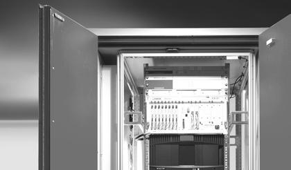
 Aspiration and exhaust air connections 7) Emergency power supply (accumulators) 8) Main board 9) Power supply unit 10) Front panel with display and control panel 11) Detector")
8 2.2 Design 1) Extinguishing agent container with level monitoring, overpressure protection and electric release device 2) Propelling gas cartridge 3) Extinguishing nozzle 4) Fire sensors 5) Aspiration fan 6) Aspiration and exhaust air connections 7) Emergency power supply (accumulators) 8) Main board 9) Power supply unit 10) Front panel with display and control panel 11) Detector interface 12) Filter for air flow monitoring Function Via a pipe system a fan (5) constantly sucks air samples from the monitoring area (6) and passes them via the fire sensors (4). The sensors are monitored permanently by the evaluation and control electronics (8) for functionality and potential soiling. 2 1 When the first fire alarm criterion is reached, the evaluation electronics controls the process 10 programmed for this event: It displays the alarm condition on a display (10), if necessary triggers the transmission to superordinated systems, controls optional acoustic and optical alarm devices. When the second alarm criterion is reached the release device (2) will be electrically triggered after a preset analysis time, opening the propelling gas cartridge (2) and causing the propelling gas to flow into the extinguishing agent container (1). The propelling gas presses the extinguishing agent through an extinguishing pipe towards the extinguishing nozzle (3). At this nozzle the extinguishing agent evaporates and builds up the necessary extinguishing concentration for extinguishing the fire. The extinguishing agent container is protected against overpressure. The filling level monitor integrated into the extinguishing agent container reports a loss of extinguishing agent to the evaluation electronics which indicates this fault (extinguishing agent loss) on the display and if necessary transmits it to superordinated systems. The power supply for the is secured from 2 sources. Once source is a power supply unit (9) which also charges the batteries for the emergency power supply (7). The other source is the emergency power supply which is switched in parallel. The emergency power supply is designed for the uninterrupted operation of the system for 4 hours. DET-AC Plus - operating instructions - order no ÄI page 8/52
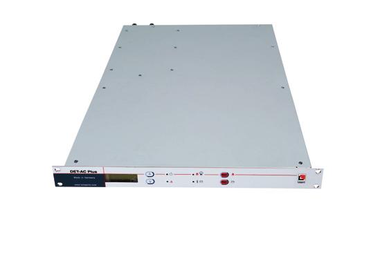
9 The control and display of the current state of the extinguishing system is achieved via the integrated control unit. This has both LED indicators and an LCD display to display the current status. The LEDs are used to display collective conditions, whereas the individual conditions are displayed in detail as clear text on the LCD. If there are several messages, the cursor keys can be used to switch between them. The existing messages are sorted in accordance with their priority and the order of arrival. If the cursor keys are not used for a duration of 30 seconds, the display switches the normal state. The display of collective conditions via the LEDs of the control unit is independent of the content of the LCD and therefore independent of the scrolling using the cursor keys. It always represents the current system state. Besides the cursor keys the control unit has another two keys for resetting stored messages. Front view Rear view DET-AC Plus - operating instructions - order no ÄI page 9/52
10 2.4 Connections ) Relay output first alarm, see ) Relay output main alarm, see ) Relay output extinguishing, see ) Relay output collective error, see ) Connector (RJ12) to connect to Rittal CMC I/O unit (door contact 1), see ) Connector (RJ12) to connect to Rittal CMC I/O unit (error) 7) Connector (RJ12) to connect to Rittal CMC I/O unit (main alarm) 8) Connector (RJ12) to connect to Rittal CMC I/O unit (first alarm) 9) Still without function - reserved for future applications 10) Two-pole plug for for manual release, see ) Two-pole plug for door contact 2, see ) Two-pole plug for external power supply (U S ), see Door contact / blocking Via the input "door switch" the release of the extinguishing system is blocked. This is necessary because the build-up of a sufficient concentration of extinguishing agent cannot be guaranteed with the door open. This blocking is displayed in the LCD and via the green flashing operating LED. Caution! All extinguishing requests registered during the condition "Extinguishing system blocked" (= blocking of the extinguishing system) place the device into the status "extinguishing system blocked" but do not cause the extinguishing action to be started. DET-AC Plus - operating instructions - order no ÄI page 10/52
.")
.")
11 a) Input "door switch" as RJ12 connector One input "door switch" (5) is designed for the model Rittal (see also figure on the left). As termination an RJ12 connector with a resistor 22 K is provided between the contacts 2 and 6 (see figure on the right). Via the connection X2 several door switches of this type can be switched in series. b) Input "door switch" as two-pole plug The additional input "door switch" (11) is a two-pole plug. The connection must be made in accordance with the adjacent drawing. The corresponding plugs are available as accessories (see list in the appendix). The connections are monitored for wire breaks and short circuits. Up to ten switches can be connected to the inputs. The resistors must be dimensioned as follows: R A : 22K Ohm, 1/10 Watt R K : 22K Ohm, 1/10 Watt Caution! In each case either the RJ12 connector or the two-pole plug may be used as input "door switch". Caution! If during a fire alarm in the status "Extinguishing system blocked" (= blocking of the extinguishing system) there is a transition from "blocking" to "blocking cancelled", e.g. by closing the door, the extinguishing action is triggered one second after the condition "blocking cancelled" has been reached Manual release By operating an optional connectable manual release the extinguishing action is triggered manually. The resistors must be dimensioned as follows: R A : 1K8 Ohm, 1/10 Watt R K : 470 Ohm, 1/10 Watt DET-AC Plus - operating instructions - order no ÄI page 11/52
12 To trigger the extinguishing action the push button "manual release" must be operated for at least 1 second. The release is always direct and independent of the condition of the automatic detectors. The programmed dual detector dependency will not be considered during manual release. The release via the input "manual release" is suppressed during an open door contact (see chapter 2.4.1) or if an external blocking is present. The alarm message of the manual release must be reset manually (see chapter 3.5.1) External power supply For external consumers there is a two-pole connection (U S ) with an output voltage of V DC. This output is protected by a 500 ma fuse and supplied with emergency current. If the power supply is exclusively from the battery (during mains failure) the voltage can drop to 21 V DC! Relay outputs The has 4 relay outputs with change-over contacts: (connection diagram see chapter 2.4.) Relay 1 Pre-alarm 1 (NO) Relay 2 Relay 3 Relay 4 Fire alarm (NO) Extinguishing (NO) Collective fault (NC) A detector has triggered. The relay remains energised until the alarm criterion is no longer present and the reset key button has been pressed. The second detector has triggered. The relay remains energised until the alarm criterion is no longer present and the reset key has been pressed. The relay is energised parallel to the release of the extinguishing function and remains energised until the reset key is pressed. The relay is energised permanently as long as there is a fault. All relays stay permanently energised when triggered. The maximum switching voltage is 30V with a maximum switching current of 0.5A and a pure resistive load. Inductive or capacitive loads require external protective circuits which must be provided by the operator. Caution! If the CMC-TC with I/O unit is connected, the relay outputs must not be used! DET-AC Plus - operating instructions - order no ÄI page 12/52


13 3. Installation, operation and control of the DET-AC Plus 3.1 Conditions for use and installation Permitted ambient temperature range: +10 C to +35 C Temperature difference between the air sucked in and the installation location of the device max. 5 C Relative humidity: up to 96 %, humidifying inside the device through temperature change is not permitted Ambient air low in dust and contamination The use in areas where gases or vapours corrosive to metal or plastic can be sucked in is not permitted The installation of the device in areas with vibrations caused e.g. by nearby punching machines is not permitted Operation only with closed cooling air circuit within the airtight closed cabinet or closed cabinet without ventilation (see drawings below), the air exchange rate of the switch cabinet system to be protected must not be greater than 10 % within 20 min. Max. permitted protection volume: 3 m 3 (condition: small opening surface) An empty unit in the upper third, preferably the top slot, of the cabinet Existing minimum installation depth of 850 mm 100/240 Volt mains connection Installation of the DET-AC Plus in a cabinet with open cooling air circuit is not possible! Installation of the DET-AC Plus in a closed cabinet with closed cooling air circuit is possible. Installation of the DET-AC Plus in a airtight closed cabinet without cooling air circuit is possible. Installation of the DET-AC Plus Active Fire Extinguishing System in differently equipped racks only after prior consultation. DET-AC Plus - operating instructions - order no ÄI page 13/52
14 3.2 Installation and commissioning of the device Note Always retain the transport packaging of the DET-AC Plus Active Extinguishing System. For maintenance or repair the device may only be sent in the special original transport packaging or a equivalent one. Scope of delivery Besides the actual device the scope of delivery of the DET-AC Plus Active Extinguishing System includes the following components: These operating instructions 4 screws each M5 and M6 to electively attach the device via the front panel to the 19" frame mains cable (protected IEC power plug) Recommended accessories: standard set of sampling pipes sliding rail of varying depth Note Ensure early on that the cabinet to be protected meets all space and installation option requirements to enable the proper installation of the DET-AC Plus Active Extinguishing System. During installation consider the switching off of electrical devices within the monitoring area during a fire in order to remove the supporting electric energy early on Installation notes Caution! All tasks developing smoke and dust (smoking, soldering, cleaning etc.) must be prevented during installation and commissioning of the device! It is possible for an alarm to be triggered during commissioning! It must be ensured that any controls downstream from the device (e.g. additional extinguishing systems or transmitted messages) have been switched off beforehand! DET-AC Plus - operating instructions - order no ÄI page 14/52
 and the bores of the sampling pipe are directed against the")
.")

15 The device must be positioned in the upper third, preferably the top slot, of the 19" cabinet to be protected in order to achieve a fast extinguishing action. Care must be taken that the sampling pipe at the intake side of the air conditioning unit is installed vertically (see adjacent drawing) and the bores of the sampling pipe are directed against the air flow the nozzle is positioned in such a way that within a radius of 200 mm around the nozzle spraying is not obstructed by anything other than the cabinet wall (e.g. cables or energy rails). This must also be observed without fail during any future changes within the cabinet! An adapter piece to move the nozzle position, e.g. for deeper cabinets, is available as an option (see accessories). Caution! After installation a trigger test must be carried out (see 7.1.6)! Before the trigger test the door must be opened to block the extinguishing action. This must be checked via the green flashing operating LED and the indication "extinguishing system blocked" in the display. After the trigger test at least 2 minutes must pass to allow the test gas concentration in the detector heads to dissipate and the alarm must be reset. No fire message (red LED) may be indicated before the blocking is cancelled by closing the doors, otherwise the extinguishing action will be initiated! Caution! Installation position: The DET-AC Plus must be installed in a horizontal position (aligned with spirit level) to ensure that the extinguishant can be discharged completely. DET-AC Plus - operating instructions - order no ÄI page 15/52
 Installation steps: Check the temperature indicator for proper condition (see figure 1) If the temperature indicator is dark, it is")
 to support the device Open the cover plate of the battery compartment Attach the plug of the batteries for emergency power supply to the free plug")

. Therefore great care is required during the following installation steps!")
16 3.2.2 Installation steps and functional test Caution! Please always carry out the installation steps in the order given below. Record the steps in the installation and test report (see appendix) Installation steps: Check the temperature indicator for proper condition (see figure 1) If the temperature indicator is dark, it is possible that the positive pressure safety device of the extinguishing tank was released. In this case with start-up the message "fire extinguishing agent decrease" is indicated in the display. Install the sliding rails (supplied by customer) to support the device Open the cover plate of the battery compartment Attach the plug of the batteries for emergency power supply to the free plug contact. Thus the batteries are attached in 24 V function! (see figure 2) Caution! The battery must only be connected if it is immediately followed by connecting the mains supply since otherwise the batteries will be discharged! Screw the cover plate of the battery compartment back Screw in the transport protection pin (see figure 3a) of the extinguishing unit up to the stop Caution! After this step the device is ready for operation and release (see figure 3b). Therefore great care is required during the following installation steps! Slide the device horizontally onto the sliding rails. Ensure that the device slides in easily without jamming up to the stop of the font panel at the frame Attach the device to the front panel using four of the screws and block plastic washers included through the holes of the front panel in the 19" frame (see figure 4) Install the sampling pipe (see chapter 3.2.3) Connect the device to the 100/240 V power supply Press the button "reset mains fault" For the subsequent functional tests of the device and of additional devices see commissioning and test report (see 7.1); connection of additional electrical devices see chapter 3.3 Temperature indicator bright: OK Figure 1 Temperature indicator 54 C Temperature indicator dark: Caution, temperature was exceeded! Figure 2 Connecting the batteries Figure 3a Transport protection pin (the device in the blocked condition) Figure 3b Transport protection pin (the device is not blocked any more!) Figure 4 Attachment in the cabinet DET-AC Plus - operating instructions - order no ÄI page 16/52
. See also the photo below.")
 using the clamps.")
17 3.2.3 Installation notes for the sampling pipe Caution! Air intake (sampling pipe connection): Ensure the correct connection of the sampling pipe (air intake) to the device! Never connect to the air flow return (air outlet). See also the photo below. Air outlet: An L-shaped plug-in connection (angle) with the opening facing downwards must be fitted to the air outlet to comply with IP 20. The vertical sampling pipe must be attached at a location aiding the flow (bores of the sampling pipe directed against the air flow) using the clamps. The diagrams on the following page indicate the fans. It is assumed that the fans on the side of the sampling pipe aspirate air from the cabinet. The 4 holes in the sampling pipe must be directed away from the fans towards the cabinet! 2 1 The sampling pipe is sealed with an angle and a plug at the bottom. A trigger test using test aerosol must always be carried out! (Caution, to do so block the extinguishing system, see 7.1.6) Caution! The following figures are recommendations. Other arrangements for fans and air conditioning devices might require a different position of the sampling pipe. The installation of the device must always be coordinated with the operator. During future changes of the cable configuration the bores of the sampling pipe have to remain free. The pipe system must not obstruct the future cable routing within the cabinet! DET-AC Plus - operating instructions - order no ÄI page 17/52

 The angle is sealed with a plug at the")

18 Sampling pipe installation options Installation of the sampling pipe with routing on the left cabinet side Installation of the sampling pipe with routing on the right cabinet side Air inlet of the A/C system with recirculating air operation Detail: sampling hole Sampling pipe with 4 holes (3 mm diameter each) The angle is sealed with a plug at the end In racks without air conditioning a varying installation of the sampling pipe can be needful. DET-AC Plus - operating instructions - order no ÄI page 18/52
 Mark the")
 (use guiding line at the pipe")
 2) Insert pipe loosely 3) Press")

 Press the fixing")
 5) Pull")
 pressed down DET-AC")

19 Installation of the sampling pipe a b b 4 5 c c Installation of the sampling pipe 1) Mark the insertion depth (a) of the pipe (b) (use guiding line at the pipe angle!) 2) Insert pipe loosely 3) Press in the pipe strongly until the stop can be heard and felt and up to the marking (b) Removal of the sampling pipe 4) Press the fixing element (c) down (only visible as a ring from the outside) 5) Pull out the pipe with the fixing element (c) pressed down DET-AC Plus - operating instructions - order no ÄI page 19/52
20 3.3 Installation and commissioning of additional electric devices After the proper installation and commissioning of the DET-AC Plus Active Extinguishing System additional electric devices can be connected. Caution! Connection of additional electric devices: For the connection of additional electric devices the following information must always be observed: It is possible for an alarm to be triggered during commissioning! It must be ensured that any controls downstream from the device (e.g. additional extinguishing systems or transmitted messages) have been switched off beforehand! Before the functional test the door must be opened to block the extinguishing action. This must be checked via the flashing green operating LED and the indication "extinguishing system blocked". No fire message (red LED) may be indicated before the blocking is cancelled by closing the doors, otherwise the extinguishing action will be initiated! The conditions must be checked in accordance with the commissioning and test report External alarm devices External alarm devices, e.g. flashing lights and/or alarm horns (see also chapter spare parts and accessories) can be connected to the relay outputs pre- and main alarm (see relay outputs) Push button for manual release To connect the push button for manual release the sequence in the commissioning and test report (see 7.1) must be observed. DET-AC Plus - operating instructions - order no ÄI page 20/52
21 3.4 s and faults The correct operating state of the DET-AC Plus is indicated by a permanently illuminated green operating LED (1). If a fire alarm or faults occur, they are indicated on the LCD display (2) and by fault LED (3) or alarm LED (4). The DET-AC Plus must therefore be installed in a clearly visible location and monitored by an overriding system, if necessary and fault messages messages The DET-AC Plus can implement two alarm levels with different indications and controls via two sensors responding at different sensitivities. The respective indications and their meanings are explained in the table "LCD display indications" below. Fault messages The DET-AC Plus monitors the most important functions itself. Faults are indicated and reported externally, if applicable. The respective indications and their meanings are explained in the table "LCD display indications" below. Caution! In case of a fault the proper functioning of the device is not guaranteed. If a fault message arrives it might not be possible to detect and extinguish a fire! Therefore, the cause of the fault message must be immediately removed! Caution! Before the functional test the door must be opened to block the extinguishing action. This must be checked via the flashing operating LED and the indication "extinguishing system blocked". No fire message (red LED) may be indicated before the blocking is cancelled by closing the doors, otherwise the extinguishing action will be initiated! DET-AC Plus - operating instructions - order no ÄI page 21/52
22 3.5 Display and control elements To display the current device state the extinguishing system has an LCD with background illumination and four LEDs to indicate collective conditions. Operation is via four keys on the front. LCD display Operation LED 'Up' key '' key '' LED Status OK * 'Down' key 'Collective fault' LED PS* fault LED ' PS' key Figure 1: Display and control elements *PS = Power Supply LED indications The collective indications are implemented via four LEDs on the front. These are activated in accordance with the indication types in Table 1. Type of indication off flashing blinking on Activation LED is permanently off LED is energised every 2 seconds for 200 ms LED is alternately on for 0.5 seconds and off for 0.5 seconds LED is permanently on Table 1: LED indication types DET-AC Plus - operating instructions - order no ÄI page 22/52
23 The four LEDs implement the following indications: LED Colour State Meaning Operation green off on blinking flashing System disconnected or not ready for operation System ready for operation System in operation, but extinguishing is blocked (e.g. door open) The system is being reset red off flashing blinking on System at rest A detector has triggered with dual detector dependency programmed, but the other is still inactive (pre-alarm) A fire alarm has been detected but no extinguishing action has been triggered (e.g. because of a blocking present) The extinguishing action has been triggered Collective fault yellow off blinking blinking on No faults (except possibly power supply unit faults) are present In conjunction with operating LED off: the central control station has failed or there is no communication between the central control station and the control panel In conjunction with operating LED on: faults are present which prevent an extinguishing action if requested Faults are present which do not prevent an extinguishing action Fault Power supply unit/charger (PS) yellow off blinking on Power supply unit / charger work properly Mains power supply failure There are faults in the power supply unit / charger Table 2: Meaning of the LED indications Caution! Faults of the power supply unit / charger are not included in the collective fault indications. This means that the collective fault LED will not be activated if only faults of the power supply unit / charger are present. If faults of the power supply unit / charger are present and the collective LED is also activated in any way, this means that other faults in addition to the power supply unit / charger faults are present. DET-AC Plus - operating instructions - order no ÄI page 23/52
24 3.5.2 Keys System operation is via four keys located on the front of the device. For the functions of the keys it is differentiated whether the system is in the state 'Message display' (normal state) or whether a control menu is active. Key Function In the message display In the menus Up if other older messages are present, previous menu entry they can be called using this key (scrolling) Down PS if other more recent messages are present, they can be called using this key (scrolling) currently stored messages are deleted battery faults are reset (if they are no longer active) Table 3: Function of the control keys next menu entry Cancels the selected functions or exits the current menu level (ESC). If a submenu is active this returns to the main menu. In the main menu the key returns to the message indication (exiting the control menu). Enables the selected function or accepts the settings (Enter). If this key is pressed in the main menu for an entry referring to a submenu, the submenu is activated. If no submenu exists, the allocated control function is activated. DET-AC Plus - operating instructions - order no ÄI page 24/52
25 3.5.3 LCD display The LCD display is used to display the individual current messages in text format. The LCD is also used to permit the menu-guided control of the system. Message display Normal state In the normal state of the message display the most recent current message is displayed in the LCD (Figure 2). Message number = number of messages currently present 4 Extinction successful Other older messages are present which can be called using the "Up" key Message text Figure 2: Normal state of the message display If no current message is present, the message in is shown in the LCD. Status OK * Figure 3: Display without messages To indicate operability the character '*' runs from left to right through the screen in the lowest line. As soon as at least one message is present, the display automatically changes to the normal state of the message display. Scrolling through messages If more than one current message are present, the individual messages can be viewed (scrolling) using the arrow keys ('Up' and 'Down'). The message display then shows a symbol indicating that other more recent events then the one currently being displayed are present (Figure 4). DET-AC Plus - operating instructions - order no ÄI page 25/52
26 Number of this message Other older messages are present which can be called using the "Up" key 3 Trigger extinguishing system Message text Other more recent messages are present which can be called using the "Down" key Figure 4: Scrolling through messages If no entry is being made in this state for 30 seconds the display automatically changes to the normal state of the message display (display of the most recent message). Control menus If the control panel is in the 'Message display' state, the control menu is activated by simultaneously pressing both arrow keys ('Up' and 'Down'). This operation activates the main menu and its first entry (event memory) will be shown. The control menu can be exited by pressing the '' key, if the main menu was active. An activated control menu is automatically exited if no entry is made for 30 seconds. The display then always changes to the normal state of the message display. DET-AC Plus - operating instructions - order no ÄI page 26/52
27 Main menu Control function "View event memory": previous menu item Event memory next menu item exit menu select function Submenu "Air flow calibration": Air flow calibration previous menu item exit menu next menu item activate submenu Control function "Lamp test": Lamp test previous menu item exit menu next menu item select function Submenu "Version query": Version information previous menu item exit menu next menu item activate submenu Control function "Battery change": Battery change previous menu item exit menu next menu item select function DET-AC Plus - operating instructions - order no ÄI page 27/52
28 Submenu Air flow calibration Control function "Display of the current air flow measurement": previous submenu item main menu Air flow indication next submenu item select function Control function "Automatic calibration of air flow monitoring": previous submenu item main menu Automatic air flow calibration next select function submenu item Control function "Manual calibration of air flow monitoring": previous submenu item main menu Manual air flow calibration next submenu item select function Control function "Adjusting the integration time for air flow monitoring": previous submenu item main menu Filtering time next submenu item select function DET-AC Plus - operating instructions - order no ÄI page 28/52
29 Submenu Version information Control function "Querying the firmware version": previous submenu item Firmware version next submenu item main menu select function Control function "Querying the version of the control panel software": previous submenu item main menu Control panel version next submenu item select function Control function "Querying the BIOS version": previous submenu item BIOS version next submenu item main menu select function DET-AC Plus - operating instructions - order no ÄI page 29/52
30 Description of the menu functions Querying the firmware version Firmware version OneU-CPU menu menu menu menu The following information is shown: device name, version number and date of version creation. Querying the version of the control panel software Control panel version menu OneU BT menu menu menu The following information is shown: device name, version number and date of version creation. Querying the BIOS version BIOS version menu menu (03) HW: menu menu The following information is shown: version number and hardware ID. DET-AC Plus - operating instructions - order no ÄI page 30/52
31 View event memory The display of messages from the event memory is identical to the message display of the system. To indicate that this is a display from memory the text 'EMEM' is shown at the top right. Unlike in the message display, messages are also entered in the event memory if a state causing a message has been removed. The display of the current message is either by way of a correspondingly different text message (Figure 5) or using the same message plus the symbol for current messages. 162 EMEM Door contact at rest 162 EMEM Trigger extinguishing system Figure 5: current message 1 Figure 6: current message 2 The number of the message is numbered from the start of the current event memory. I.e. the oldest event still present in the memory has the number 1. If the event memory is full, the next event overwrites the so far oldest event. During the next display of the event memory the event previously carrying the number 2 now carries the number 1 (the stored events move down to allow the new event to be inserted at the top). The numbering in the event memory has no relation to the number shown for the event in the message display when the event was still current. In the display of the event memory one can change from any entry to the chronologically oldest event by simultaneously pressing the two arrow keys 'UP' and 'down'. Likewise the key 'RESET EV' always leads to the chronologically recent event. If one keeps the respective arrow key longer pressed while scrolling, the display continues to run automatically into the selected direction, as long as the key remains pressed. Display if no entries are present in the event memory exit EMEM display exit display exit display exit display Display of the most recent event 162 EMEM Door contact at rest to previous message exit display no function no function By activating this control function "View event memory" the most recent message in time will always be displayed. Changing to older messages is possible using the arrow key "Up". The symbol at the top right of the display indicates that older messages are present. DET-AC Plus - operating instructions - order no ÄI page 31/52
32 Display of an event within the memory to previous 161 EMEM message Door contact blocked to next message exit display to recent message The symbol present. at the bottom right of the display indicates that more recent messages are Display of the oldest stored event 1 EMEM Trigger extinguishing system no function to next message exit display to recent message Display of the current air flow measurement (1) (2) (3) no function no function (4) exit display exit display (1) currently set lower limit value for monitoring (2) current measurement (3) currently set upper limit value for monitoring (4) display of the current measurement as a bar graph The current measurements and the currently set monitoring thresholds are shown. The measurement is updated cyclically to show changes. DET-AC Plus - operating instructions - order no ÄI page 32/52
33 Automatic calibration of air flow monitoring Determination of the current values The current values are determined! The displayed value counts up to 64 (progress indication). No operation is possible during this phase. Please wait for this phase to complete. (1) (2) (3) -20% 20% (4) enlarge monitoring window minimise monitoring window cancel function confirm current value (1) currently set lower limit value for monitoring (2) current measurement (3) currently set upper limit value for monitoring (4) display of the current measurement as a bar graph The current measurement is determined and the corresponding thresholds are calculated from it in accordance with the selected width of the monitoring window (±10 %, ±20 % or ±40 %). The determined values have to be confirmed to become effective (key PS). DET-AC Plus - operating instructions - order no ÄI page 33/52
34 Manual calibration of air flow monitoring Determination of the current values The current values are determined! The displayed value counts up to 64 (progress indication). No operation is possible during this phase. Please wait for this phase to complete. (1) (2) (3) -20% 20% (4) increase monitoring range decrease monitoring range cancel function confirm current value (1) currently set lower limit value for monitoring (2) current measurement (3) currently set upper limit value for monitoring (4) display of the current measurement as a bar graph The set monitoring range is moved as a whole (lower and upper threshold simultaneously). If the width of the currently set monitoring range (here ±20 %) is to be changed, an automatic calibration must first be carried out! The set values have to be confirmed to become effective (key PS). Adjusting the integration time for air flow monitoring increase filtering time 3s decrease filtering time cancel function confirm current value If an arrow key is held pressed for more than 3 seconds, the value automatically changes up or down. Due to the communication method between the main processor and the control panel there is a small delay between pressing the key and the system response. This results in the value still being increased or reduced by approx. 2 when a key is released which was previously held down. The automatic function is only disabled afterwards. Simultaneous pressing of the keys and sets the value to 0. The set value has to be confirmed to become effective (key PS). Lamp test All segments of the LCD are blanked in black and all LEDs are switched on permanently. exit test display exit test display exit test display exit test display The lamp test is exited when any key is pressed. If no key is pressed for more than 5 seconds, the lamp test is automatically exited. DET-AC Plus - operating instructions - order no ÄI page 34/52
35 Battery change The period of operation of the batteries is monitored by the system. If it exceeds the maximally permissible time, an appropriate message is displayed and the system goes into the failure mode. In order to reset this monitoring after a battery change, the function battery change must be called up. Since the system cannot recognise the exchange of the batteries automatically, the function must be called up also if the battery exchange takes place, before the failure message appears. Otherwise the operating hours meter for the batteries is not put back and the failure message would come before expiration of the permissible period of operation. After the start of the function the inquiry takes place: confirm yes change Batteries were changed? cancel no function cancel function cancel function If this question is answered with yes, the resetting of the operating hours meter must be confirmed in the following dialogue: Please confirm battery change with PS! cancel function cancel function cancel function carry out function If the function was carried out the following confirmation message appears: Battery change was saved. menu menu menu menu After this message the operating hours meter of the batteries is reset, so that the entire maximum period of operation is available again. A failure message with the request to change the batteries eventually displayed before is reset thereafter. If the function is discontinued in any position, a warning message appears: Battery change was not confirmed! menu menu menu menu If this message appears, the operating hours meter of the batteries was not reset, it keeps running from the temporally last condition. A failure message with the request to change the batteries eventually displayed before is not reset thereafter. DET-AC Plus - operating instructions - order no ÄI page 35/52
36 Operating hours meter Apart from the monitoring of the operation hours of the batteries the system evenly monitors the period of operation since the last maintenance. If this exceeds the maximum maintenance interval, a failure message is generated. For resetting this message a fabricator reset must be carried out. For this purpose the housing of the OneU must be opened. On the CPU board the key '' is to be pressed for longer than 3 seconds. Afterwards the failure message to the maintenance interval is deleted and the operation hours meter of the system reset. This resetting does not have any influence on the monitoring of the period of operation of the batteries LCD display - List of messages For the following conditions messages will be displayed on the LCD display: Display text Extinguishing action triggered Fire Manual release Manual release fault External blocking Fire alarm detector 1 Fire alarm detector 2 Blocking by door contact Door contact fault Mains failure Display text meaning Both sensors have triggered a fire alarm or on of them triggered a fire alarm and the other one reported a fault and activated the extinguishing release as a result. Both sensors have triggered a fire alarm or on of them triggered a fire alarm and the other one reported a fault without triggering the extinguishing action. An externally connected push button for manual release has been released. An externally connected push button for manual release is faulty or the line to it is faulty. The extinguishing release is blocked by a door contact switch or an external contact. The first sensor has detected a particle with typical fire characteristics in the intake air. The second sensor has detected a particle with typical fire characteristics in the intake air. A cabinet door is open and the door contact for suppressing the extinguishing action is enabled, the extinguishing system cannot be triggered. or A terminating resistor for the door switch is missing A connected door contact switch is faulty or the line to it is faulty. The mains voltage is missing or the power supply unit is faulty. DET-AC Plus - operating instructions - order no ÄI page 36/52
37 Display text Battery fault Charging fault Air flow fault, dynamic pressure too high Air flow fault, dynamic pressure too low Detector 1 fault Detector 2 fault Extinguishing output fault Extinguishing agent loss Extinguishing agent monitoring fault Maintenance interval expired Battery change required Triggering extinguishing system Extinguishing fault Extinguishing successful Battery failure Failure battery loading Reboot Cold start Quiescence Display text meaning One or both batteries are missing, not connected, fully discharged or are not being charged. The charging does not function correctly. Contamination or blocking of the sampling pipe or of individual holes. Fracture or torn connection of the sampling pipe or Change in ambient conditions (changed flow velocities of an air conditioning system, open or closed doors of the 19" cabinet, etc.). Sensor 1 is missing, does not make contact or is faulty. Sensor 2 is missing, does not make contact or is faulty The electric release device cannot be actuated. The extinguishing agent volume has reduced due to loss The monitoring device of the extinguishing agent is faulty After approx. 2 years the device needs to be serviced. Call service engineer. Battery life of 4 years has been exceeded. Call service engineer. Extinguishant tank was triggered Extinguishant tank was triggered but filling level indicator does not indicate loss of extinguishant Extinguishant tank was triggered and filling level indicator indicates loss of extinguishant Fall below the final discharging voltage Batteries cannot be loaded any longer Device accomplished a restart during the normal operation key of the processor board was pressed Device is in the normal operating condition DET-AC Plus - operating instructions - order no ÄI page 37/52
38 4. Behaviour during a fire Caution! This information does not replace the locally prescribed behaviour during a fire in any way but serves as additional information about the behaviour during alarms/fires or triggering of the extinguishing system in a cabinet protected by a DET-AC Plus active extinguishing system! Measures in case of an alarm in a cabinet protected by a DET-AC Plus Active Extinguishing System: Always keep the cabinet doors closed during the hold time (10 minutes). If the concentration required for extinguishing drops due to ventilation, any still existing source of ignition might flare up again. If no fire or smoke can be seen, the cabinet can be ventilated with extinguishing aids (e.g. carbon dioxide fire extinguisher) at the ready. Release of the DET-AC Plus The release of the DET-AC Plus takes place immediately after the fire alarm. A fire alarm is triggered by the actuation of both automatic fire detectors or operation of the push button for manual release. If the extinguishing system is triggered manually via the push button for manual release, the release takes place immediately without time delay. The presence in rooms flushed with the extinguishing agent Novec 1230 is harmless but should be avoided, because smoke development may endanger life due to toxic combustion products. DET-AC Plus - operating instructions - order no ÄI page 38/52
39 5. Control, service, maintenance and repair after release The operator carries out the regular visual inspections at the device himself. The maintenance and repair of the device is carried out by the Lampertz / Rittal Service or a specialist company authorised by Lampertz / Rittal. A specialist company authorised for maintenance and fault removal is a company whose employees have been trained by Lampertz / Rittal in the DET-AC Plus Active Extinguishing System. Normally this is a member of the installation company or a specially trained employee of the operator or a specialist company commissioned by him. In case of improper handling and faulty or missing regular inspections and maintenance Lampertz / Rittal does not accept any liability. 5.1 Regular inspections by the operator Daily inspections (operator) No fault may be present in the DET-AC Plus. (operating state without fault or alarm: green operation LED is on, no yellow fault LED is on or flashing). Any faults present must be recorded and removal must be initiated. Daily inspections may be omitted if it can be ensured that any faults are safely detected elsewhere. Monthly inspection (operator) Sampling pipe and extinguishing nozzle must be free of external damage and the nozzle must be free of contamination and obstacles in the spray Sampling pipe connections must not be disconnected Display air flow and compare with the value from the commissioning report to detect any contamination. The max. deviation must not exceed 10 %. Quarterly inspection (operator) This should additionally investigate any constructive modifications (especially with regard to the air tightness of the cabinet: the air exchange rate of the switch cabinet system to be protected must not be greater than 10 % within 20 min) or changes in use, and the device should be checked for the proper operation of the alarm, fault and control functions. DET-AC Plus - operating instructions - order no ÄI page 39/52
40 5.2 Tests, maintenance and repairs Caution! During maintenance work at the device an alarm may / should be triggered! It must be ensured that any controls downstream from the device (e.g. transmitted messages or shut-off device) have been switched off/bridged beforehand! Semi-annual maintenance (Lampertz / Rittal or specialist company) Visual inspection, complete service (e.g. test and, if necessary, clean sampling pipe and extinguishing nozzle, check cover seal, replace filter for air flow sensor, if necessary, check air flow calibration and adjust, if necessary) plus operational check. The history memory must be checked for errors (see View event memory ). Biennial maintenance (Lampertz / Rittal or specialist company) At least every two years the DET-AC Plus must be serviced by Lampertz / Rittal Service or a specialist company authorised by Lampertz / Rittal. During this maintenance the system is fully tested and, if necessary, returned to the target condition. Non-observance of these intervals may cause faults or false alarms. After 4 years, in the context of the second 2 biennial maintenance, the batteries for the emergency power supply must be renewed. DET-AC Plus - operating instructions - order no ÄI page 40/52
41 5.2 Notes on transport During the transport of the device with extinguishing agent container and propelling gas cartridge 25,3 g (85 ml) Argon the following special rules must be taken into account. Special notes on transport for overland transportation Hazardous substance: UN 1006, category 2, limited quantity LQ1* as per ADR 2007 Special notes on transport for sea transportation Hazardous substance: UN 1006, category 2.2 (argon, compressed), limited quantity* IMDG code Special notes on transport for air transportation UN 1006, category 2.2 (argon, compressed), IATA-DGR no limited quantity *for limited quantity: most permissible net quantity for each interior packing 120 ml argon, gross weight per package max. 30 kg The safety data sheet for Novec 1230 by 3M must be observed and is included with the device during delivery. Packaging Always retain the transport packaging of the DET-AC Plus. For maintenance or repair the device may only be sent in the special original transport packaging or a equivalent one. DET-AC Plus - operating instructions - order no ÄI page 41/52
42 6. Technical data Housing dimensions 19, 1HE, 850 mm deep (sheet metal) Weight approx. 25 kg incl. extinguishing agent and propelling gas cartridge Nominal voltage 100/240V AC, 50/60Hz Emergency power supply approx. 4 h Ambient temperature +10 C to +35 C (operation), -20 C to +65 C (storage) Humidity up to 96 %, non-condensing Protection category IP 20 Connections 1 potential-free change-over contact "pre-alarm" (RJ12 connector) 1 potential-free change-over contact "fire" (RJ12 connector) 1 potential-free change-over contact "extinguishing" (RJ12 connector) 1 potential-free change-over contact "collective fault" (RJ12 connector) 24 V -3/+5 V nominal voltage / 0.5A, resistive load Displays 1 LCD with clear text display of status messages 1 LED green "operation" 1 LED red "alarm" 1 LED yellow "collective fault" 1 LED yellow "power supply unit/charger fault" Sensors (2 different scattered light sensors for 2 alarm thresholds) Sampling pipe Sampling holes Air flow monitoring Protection volume optical smoke detector (sensitivity: approx. 3.5 %/m light obscuration) optical smoke detector HS (sensitivity: approx %/m light obscuration) glueless connector system, black (outer diameter: 22 mm, inner diameter: 18 mm) min. 4 sampling holes, diameter: 3 mm approx. +/-10 % volume flow max. 3.0 m 3 (for airtight cabinets: the air exchange rate of the switch cabinet system to be protected must not be greater than 10 % within 20 min.) External devices connection for push button for manual release connection for door contact bus connection for system networking Rittal CMC (RJ12 connector) connection for external signalling devices Approvals electric components meets UL requirements CE conformity of the extinguishing unit per EC directive 97/23/EC Extinguishing agent container material: aluminium / steel empty volume: approx. 2.2 l content: 2 litres (= 3.2 kg) Novec 1230 extinguishing agent dispersal by pressure build-up via propelling gas cartridge with integrated electric release device integrated extinguishing agent loss / filling level monitoring (indication of > 15 % loss) DET-AC Plus - operating instructions - order no ÄI page 42/52
43 7 Appendix 7.1 Commissioning and test report Date of commissioning / commissioner: Serial number of the device: Temperature indicator Mains connection Lamp test Air flow detection Mains fault detection External voltage output OK Notes Device connected with enclosed mains cable After connecting the batteries the message "Mains failure" must appear in the display. After approx. 1 min. "power supply unit failure" will be reported and the yellow mains fault LED blinks Please enter the measured voltage (25-29 V with mains supply connected) Air flow calibration The air flow calibration must be carried out with the cabinet closed and the ventilation switched on. Immediately after starting the calibration function the door must also be closed via the control menu (see also 3.5.3). Nominal value Lower limit Upper limit Filter time Initially 10 % should be set as permitted deviation because this setting permits the earliest possible detection of a contamination of the sampling holes. If the air flow reports frequent faults due to the flow conditions, the tolerance can be raised to 20 or 40 %, which however makes the recognition of contamination more insensitive. The following measures must be carried out in the sequence described for the functional test power supply fault, reset alarm, close door. The device is in quiescent condition. LCD LED Relay Detector 1 Open Closed Detector 2 push button for manual release Door System condition x x x x OK Status OK Green on condition DET-AC Plus - operating instructions - order no ÄI page 43/52
44 7.1.3 Opening the door LCD LED Relay Detector 1 Detector 2 push button for manual release Open Closed Closed Door System condition x x x x Blocked Extinguishin g system blocked Green blinks condition Caution! The message "Extinguishing system blocked" must appear in the display otherwise the extinguishing action will be activated during the subsequent steps Disabling the system by pulling the door contact plug This is done for additional safety. Should somebody unintentionally close the door during the subsequent steps, no release will result. LCD LED Relay Detector 1 Detector 2 push button for manual release Door System condition x x x x Blocked Extinguishin g system blocked; Door contact fault Open Closed Green blinks; Yellow illuminates Fault DET-AC Plus - operating instructions - order no ÄI page 44/52
45 7.1.5 Connecting the push button for manual release. The system state must not change in the process! LCD LED Relay Detector 1 Detector 2 Open Closed push button for manual release Door System condition x x x x Blocked Exting. syst. blocked; Door contact fault Green blinks; Yellow illuminates Fault Trigger push button for manual release LCD LED Relay Detector 1 Detector 2 Open Closed push button for manual release door System condition x x x x Blocked; Exting. syst. blocked; Door contact fault; Manual alarm release; Fire Green blinks; Yellow illuminates; Red blinks Fault; Pre-alarm; Main alarm push button for manual release and press fire reset key. The state before the release will be restored. LCD LED Relay Detector 1 Detector 2 push button for manual release Door System condition x x x x Blocked Exting. syst. blocked; Door contact fault Open Closed Green blinks; Yellow illuminates Fault DET-AC Plus - operating instructions - order no ÄI page 45/52
46 7.1.6 Triggering the automatic detectors Trigger with test gas at the last hole of the air sampling pipe LCD LED Relay Detector 1 Detector 2 push button for manual release Open Closed Door System condition x x x x Blocked; Extinguishin g system blocked; Door contact fault; Fire alarm detector 1; Pre-alarm; Fire alarm detector 2; Fire Green blinks; Yellow illuminates; Red blinks Fault; Pre-alarm; Main alarm the alarm after 2 min. using the fire reset key. The previous state must be restored. LCD LED Relay Detector 1 Detector 2 push button for manual release Qquiescent Door System condition x x x x Blocked Extinguishin g system blocked; Door contact fault Open Closed Green blinks; Yellow illuminates Fault DET-AC Plus - operating instructions - order no ÄI page 46/52
47 7.1.7 Generating an air flow fault Close 10 % of the sampling holes to generate an air flow fault LCD LED Relay Detector 1 Detector 2 push button for manual release Door System condition x x x x Blocked Extinguishin g system blocked; Door contact fault Open Closed Green blinks; Yellow illuminates Fault Note: for the air flow fault detection 2 holes must be closed with insulating tape. After the set filtering time the yellow fault LED must illuminate and the message air flow too low must appear in the display Reactivate the system Refit the door contact plug, press the reset key and close the door LCD LED Relay Open Closed Detector 1 Detector 2 push button for manual release Door System condition x x x x OK Status OK Green on condition DET-AC Plus - operating instructions - order no ÄI page 47/52
48 7.2 Spare parts, accessories and consumables + tools S M Item L Order number Spare parts 1 E DET-AC Plus complete device 2 E Extinguishing tank complete, incl propelling gas cartridge 3 E Set of batteries (2x 12V/ 2.2 Ah) E Fire detector head OMX1002C E Fire detector head OMX1002C HS E Air flow sensor filter 50µm X E Fuse 0,315 A / 250 Volt X E Fuse 0.5 A / 250 Volt X E Fuse 2.0 A / 250 Volt X E Fuse 4.0 A / 250 Volt X E Fuse 6,3 A / 250 Volt (power supply unit) X E Terminator resistor 22k, 1/10 watt with RJ12 connector (door contact connection) X E Terminator 1K8 Ohm, 1/10 watt (for door contact or push button for manual release) X E Resistor 470 Ohm, 1/10 watt (for door contact or push button for manual release) X E Power cable X E German operating instructions X E English operating instructions E Sliding rail of varying depth Rittal: DK Accessories 0 Z Test gas Z Sampling pipe complete with attachment clips 0 Z combination SONFL1 MX (flashing light + alarm horn) Z Push button for manual release, yellow Tools 0 W Pipe cutter W FESTO release fork for disconnecting sampling pipe connections 2 W Phillips screwdriver for battery cover screws 2 W Size 8 open-jawed spanner for attachment angle X W Size 22 open-jawed spanner for extinguishing nozzle 2 W Size 19 open-jawed spanner for extinguishing pipe x W Vacuum lifting pad S = Service level (0 = installation / commissioning, 1 = device replacement, 2 = extinguishing module replacement, 3 = wearing parts replacement (e.g. batteries), 4 = re-commissioning after release) M = characteristic (E = spare part, W = tool, Z = accessory) L = storage location / supplier DET-AC Plus - operating instructions - order no ÄI page 48/52
49 7.3 Trouble-shooting Fault, Fault Message Possible Cause Necessary Measure Power failure Mains voltage supply short-term failed Eliminate possible disturbances of the mains voltage supply Failure power supply Power supply unit does Connect mains voltage supply again unit not deliver voltage for longer time (e.g. if mains Failure batteries and yellow LED power supply faulty Failure air stream - Pressure too high Failure air stream - Pressure too low cables is not attached) Batteries deeply discharged or batteries not connected Sampling pipe came loose Fix sampling pipe Sampling pipe badly dirty, or Filter in the air flow monitoring is dirty Failure sensor 1 Sensor 1 faulty or Sensor 1 missing Failure sensor 2 Sensor 2 faulty or Sensor 2 missing Failure door contact Short-circuit or wire break at the door contact (e.g. cable not attached), or Termination plug is missing, if no door contact is planned, or RJ12 connector and twopole plug for door contact are attached at the same time. Failure push button Short-circuit or wire break at the push button for manual release (e.g. cable not attached), termination plugs is missing, if no hand alarm unit is planned Failure extinguishant monitoring Internal wire break or short-circuit to the level sensor of the tank Loss of extinguishant Loss of extinguishant in the tank Failure release magnet Magnet or internal wiring defective Examine whether a power failure was present. If so, load batteries 24 hours in the OneU. (The fault signal must be resetable then if not, the batteries have to be exchanged). Clean sampling pipe. If disturbance furthermore exists, exchange filter. Advise service Advise service Examination of the door contact plugs. Attach cables or put in termination plugs if necessary. Examination of plugs of the push button for manual release. Attach cables or put in termination plugs if necessary Advise service Advise service Advise service DET-AC Plus - operating instructions - order no ÄI page 49/52
50 Fault, Fault Message Possible Cause Necessary Measure Extinguishing action Extinguishing action was Advise service failed released during mechanical blocking The DET AC plus detected a fire and the extinguishing action was triggered but the extinguishant tank was No data in the event memory, although messages existed Failure sensor 1, failure sensor 2, failure air stream and no air discharge There no function of the front panel, but the aspirating fan runs and there is external 24V System failure EC=0010 P= Aspirating fan does not start Test release with test gas does not work Display does not indicate anything, but the LED work OneU does not run / start, although mains voltage lies close Message Breakdown battery charge however not emptied Backup battery on the processor board is missing or empty Interface processor board / detector board defective Interface processor board / front panel defective Advise service Advise service Advise service Interface processor board Press reset button on the processor / front panel defective board, advise service Interface processor board Advise service / aspirating fan defective Test gas was not sprayed Repeat test release directly into the bore of the sampling pipe or Test gas was not sprayed in long enough. Contrast of display is misadjusted potentiometer of the front Readjust the contrast at the back panel Power supply unit defective Batteries cannot be charged any longer Start of the OneU with the batteries. Disconnect the batteries by way of trial, in order to determine whether the power supply unit takes over voltage supply. If the system fails anyway then advise service Change batteries DET-AC Plus - operating instructions - order no ÄI page 50/52


51 7.4 Declaration of Conformity DET-AC Plus - operating instructions - order no ÄI page 51/52
Operator Manual. DET AC Plus
 Lampertz www.lampertz.com Operator Manual DET AC Plus General information The is a quality product in accordance with the latest state of the technical art. As the sole supplier in Europe for mobile and
EFD Plus Early fire detection
 Early fire detection 7338.220 Assembly and operating instructions EN V.2.0 General information The EFD Plus is a quality product in accordance with the latest state of the technical art. As the sole supplier
1 measurement signal input 4-20 ma for connection to an external gas sensor 5 freely programmable alarm switching points per measuring point
 Medium - Control - System Franke & Haqenest GmbH Borngasse 1a * 04600 Altenburg Tel: 03447-499 313-0 Fax: 03447-499 313-6 email: info@mcs-gaswarnanlagen.de MCS User Guide MCS GasController Microprocessor
6100 SINGLE LOOP DIGITAL ADDRESSABLE FIRE ALARM CONTROL PANEL
 6100 SINGLE LOOP DIGITAL ADDRESSABLE FIRE ALARM CONTROL PANEL USER MANUAL Protec Fire Detection plc, Protec House, Churchill Way, Nelson, Lancashire, BB9 6RT. Telephone: +44 (0) 1282 717171 Fax: +44 (0)
ZX1e ZX2e ZX5e. Document No Issue 01 user manual
 ZX1e ZX2e ZX5e Document No. 996-130 Issue 01 user manual MORLEY-IAS ZX2E/ZX5E Fire Alarm Control Panels Table of Contents 1 INTRODUCTION... 4 1.1 NOTICE... 4 1.2 WARNINGS AND CAUTIONS... 4 1.3 NATIONAL
Algo-Tec 6500/6600 INTERACTIVE ADDRESSABLE FIRE CONTROL SYSTEM
 Algo-Tec 6500/6600 INTERACTIVE ADDRESSABLE FIRE CONTROL SYSTEM (1-4 LOOPS) USER MANUAL Protec Fire Detection plc, Protec House, Churchill Way, Nelson, Lancashire, BB9 6RT, ENGLAND +44 (0) 1282 717171 www.protec.co.uk
Digital Marine Exhaust Temperature Alarm
 Digital Marine Exhaust Temperature Alarm Model: SM007D/S INTRODUCTION COMPONENTS Marine water cooled exhaust systems are designed to withstand temperatures of up to about 120 C. However the exhaust gases
Aktivlöschsystem DET-AC III Master DET-AC III Master Active Extinguishing System
 Faster better everywhere. Aktivlöschsystem DET-AC III Master DET-AC III Master Active Extinguishing System 7338.121 Bedienungsanleitung Operating instructions Rittal GmbH & Co. KG Postfach 1662 D-35726
Entwicklung + Fertigung + Service: Heerweg 15 D, Denkendorf Tel.: / Fax.: /
 Planungsbüro + Service: Esteraustr. 10, 56379 Holzappel Tel.: 0 64 39 / 90 19 90 Fax.: 0 64 39 / 90 19 91 E-Mail: u.ramakers@umsitec.de Entwicklung + Fertigung + Service: Heerweg 15 D, 73770 Denkendorf
Fire Command Keypad. XR5 User s Guide
 Fire Command Keypad XR5 User s Guide Silencing an Alarm While the fire alarm horns, strobes, or sirens are sounding use one of the following methods to silence the alarm depending on which type of keypad
FirePro control MANUAL
 control MANUAL Door control for FailSafe (FS) motors HW version 1.3 SW version 1.4 English Table of Contents 1 Description of the Control...2 2 Safety Instructions...3 3 Mounting...4 4 Connecting...5 5
User Manual. Dryer Controller M720
 User Manual Dryer Controller M720 Hardware version 1.00 Software version 1.00 Preliminary version Manual M720 Dryer controller Page 1 of 42 Document history Preliminary version: - Created in April, 2009
FIRERAY 5000 range USER GUIDE
 FIRERAY 5000 range USER GUIDE 0044-003-04 IMPORTANT PLEASE NOTE: The beam path MUST be kept clear of obstructions at all times! Failure to comply may result in the Detector initiating a Fire or Fault signal.
TS400. Operating Manual. Test Station for Microtector II Series (G450/G460)
") Operating Manual TS400 Test Station for Microtector II Series (G450/G460) GfG GESELLSCHAFT FÜR GERÄTEBAU MBH KLÖNNESTRASSE 99 44143 DORTMUND, Germany TEL. +49 / (0)2 31 / 5 64 00 0 FAX +49 / (0)2 31 /
Operating Manual TS400 Test Station for Microtector II Series (G450/G460) GfG GESELLSCHAFT FÜR GERÄTEBAU MBH KLÖNNESTRASSE 99 44143 DORTMUND, Germany TEL. +49 / (0)2 31 / 5 64 00 0 FAX +49 / (0)2 31 /
Fire Control Panel FS5100
 Fire Control Panel FS5100 INSTRUCTION MANUAL Revision 6/02.11 Contents 1. Introduction... 5 2. Terminology... 5 3. Function... 7 4. Technical data... 7 4.1. Modules... 7 4.1.1. Type of modules... 7 4.1.2.
ZSC100 Gas Detection and Alarm System Controller
 ZSC100 Gas Detection and Alarm System Controller User Guide 1- Introduction... 3 1.1- General description... 3 1.2- Cautions and warnings... 3 2- Control panel... 4 2.1 Control panel overview... 4 2.2
3500 CONVENTIONAL FIRE ALARM CONTROL PANEL
 3500 CONVENTIONAL FIRE ALARM CONTROL PANEL USER MANUAL Protec Fire Detection PLC, Protec House, Churchill Way, Nelson, Lancashire, BB9 6RT. Telephone: +44 (0) 1282 717171 Fax: +44 (0) 1282 717273 Web:
Dryer Controller M720
 User Manual Dryer Controller M720 Hardware version 2.00 Software version 2.00 Manual M720 Dryer controller Page 1 of 60 Document history Preliminary version: - Created in April, 2009 Hardware Version 2.00,
Operating instructions
 MA00929301 09/2015 Operating instructions ED10429002 ESYLUX GmbH An der Strusbek 40 22926 Ahrensburg Germany info@esylux.com www.esylux.com 1 Table of contents 1 Using the manual 8 2 Safety instructions
Operating instructions Page 12
 Operating instructions Page 12 Refrigerator with explosion-proof interior container Read the operating instructions before switching on for the first time 7082 271-00 LKEXv 910 Disposal notes The appliance
Operating instructions Page 14. Refrigerator Read the operating instructions before switching on for the first time
 Operating instructions Page 14 Refrigerator Read the operating instructions before switching on for the first time 7085 039-00 LKv 5710 Content Disposal notes... 14 Description of the appliance... 14 Safety
Alarm System SECURE AS 302
 Alarm System SECURE AS 302 Operating Manual SECURE Light app now available! Table of Contents Before You Start.................................. 4 User Information....................................4
Löschsystem DET-AC III Slave DET-AC III Slave Extinguishing System
 Faster better everywhere. Löschsystem DET-AC III Slave DET-AC III Slave Extinguishing System DK 7338.321 Montage-, Installations- und Bedienungsanleitung Mounting, installation and operating instructions
INTELLIGENT FIRE TECHNOLOGY. Twinflex and Multipoint V3. User Guide (TO BE RETAINED BY USER) Issue 3
 Issue 3") INTELLIGENT FIRE TECHNOLOGY Twinflex and Multipoint V3 User Guide (TO BE RETAINED BY USER) 26-0340 Issue 3 Rafiki Protection Limited Rafiki policy is one of continual improvement and the right to change
INTELLIGENT FIRE TECHNOLOGY Twinflex and Multipoint V3 User Guide (TO BE RETAINED BY USER) 26-0340 Issue 3 Rafiki Protection Limited Rafiki policy is one of continual improvement and the right to change
Control Panel User Guide
 Fire Detection & Alarm System Control Panel V4.14 Control Panel User Guide (TO BE RETAINED BY USER) 26-0397 Issue 6 Fike s policy is one of continual improvement and the right to change a specification
Operating instructions Page 14. Refrigerator Read the operating instructions before switching on for the first time
 Operating instructions Page 14 Refrigerator Read the operating instructions before switching on for the first time 7084 309-00 LKUv Disposal notes The appliance contains reusable materials and should be
E21.X.01.6C-05 Operating Manual EB2000 MC page 1. Operating manual EB2000 MC. for up to 9 sensor modules. Version 3.0
 E21.X.01.6C-05 Operating Manual EB2000 MC page 1 Operating manual EB2000 MC EASYBUS-display with MIN-/MAX-alarm for up to 9 sensor modules Version 3.0 Pursuant to EN 50 081-1 and EN 50 082-2 for unlimited
Interactive Fire Control Panel IFS7002 four signal loops Instruction Manual
 Interactive Fire Control Panel IFS7002 four signal loops Instruction Manual Revision 6/01.17 Contents 1. Introduction... 6 2. Terminology... 6 3. Function... 8 4. Technical data... 8 4.1. Physical configuration...
REPEATER FS5200R INSTRUCTION MANUAL
 REPEATER FS5200R INSTRUCTION MANUAL Instruction Manual Page1 CONTENTS 1. Introduction... 3 2. Function... 3 3. Technical data... 3 4. Contents of delivery... 4 5. General information... 5 6. Duty Mode...
CoMo-Control. Operating Manual. English (translation of original instructions) Documentation no.: a
 Documentation no.: a") Operating Manual English (translation of original instructions) Documentation no.: 3404207a Trademarks The trademarks of other companies are exclusively used for the products of those companies. Copyright
Operating Manual English (translation of original instructions) Documentation no.: 3404207a Trademarks The trademarks of other companies are exclusively used for the products of those companies. Copyright
Operation & Maintenance Manual
 Operation & Maintenance Manual for Model 2100 Fire+Smoke systems from Smoke Guard, Inc. 287 N. Maple Grove - Boise, ID 83704 Phone: (800) 574-0330 Fax: (208) 639-7851 E-Mail: info@smokeguard.com Website:
GAS EXTINGUISHING SYSTEMS COMPACT EXTINGUISHING SYSTEMS. OneU. Fire Protection Systems for 19" Racks
 GAS EXTINGUISHING SYSTEMS COMPACT EXTINGUISHING SYSTEMS OneU Fire Protection Systems for 19" Racks SMALL BUT IT systems once occupied an entire area of a computer center but now are typically combined
DYGIZONE GJD910 Lighting Controller & Enunciator
 DYGIZONE GJD910 Lighting Controller & Enunciator MASTER WIRING IDENTIFICATION Power up to the DygiZone and you will see: All the LED s (red,yellow,green and blue buttons) will flash All the LCD icons will
User Guide
 ABS control panel CP 112 212 ON ON ON ON ON ON User Guide www.absgroup.com ii ABS CONTROL PANEL CP 112 212, USER GUIDE Copyright 2008 ABS Group. All rights reserved. This manual, as well as the software
Connections, displays and operating elements C D E G H. Installing the control unit
 1 2 3 GB Control unit 0-10 V REG-K/3-gang with manual mode Operating instructions Art. no. MTN646991 ¼ DANGER Risk of fatal injury from electrical current. All work on the device should only be carried
Refrigerated air dryers
 Refrigerated air dryers OPERATING AND MAINTENANCE MANUAL Original instructions 38178800319 OPERATING AND MAINTENANCE MANUAL - Contents 1 CONTENTS CONTENTS... 1 Chapter 1 IDRY ELECTRONIC CONTROLLER...
Syncro AS. Analogue Addressable Fire Control Panel. User Manual
 Syncro AS Analogue Addressable Fire Control Panel User Manual Man-1100 Issue 02 Nov. 2008 Index Section Page 1. Introduction...3 2. Safety...3 3. Panel Controls...4 3.1 Access Level 1...4 3.2 Access Level
Watchguard WGAP864 User Manual
 Watchguard WGAP864 User Manual v1.0 Issued September 2016 1 2 Table of Contents Glossary... 5 1. Introduction to your Watchguard WGAP864... 6 2. Before Operating your Alarm System... 6 3. Understanding
IMR IX176 Portable Gas Detector User Manual
 IMR Portable Gas Detector User Manual Read this manual carefully before using this device. (727) 328-2818 / (800) RING-IMR Fax: (727) 328-2826 www.imrusa.com Ver. 1.0A4 CONTENTS SERVICE GUIDELINES... 3
U ser's Guide PC6010
 User's Guide PC6010 Quick Reference Guide This manual is for Basic and Advanced users. Each of these types of user can access a different set of functions. The and symbols next to the title of each procedure
Interactive Fire Control Panel IFS7002 one signal loop Instruction Manual
 Interactive Fire Control Panel IFS7002 one signal loop Instruction Manual Revision 4/01.17 Contents 1. Introduction... 6 2. Terminology... 6 3. Function... 8 4. Technical data... 8 4.1. Physical configuration...
CSP-204 CSP-208 CSP-104 CSP-108
 Fire Alarm Control Panel CSP-204 CSP-208 CSP-104 CSP-108 Operation manual Firmware version 1.1 csp-x_o_en 06/15 SATEL sp. z o.o. ul. Budowlanych 66 80-298 Gdańsk POLAND tel. 58 320 94 00 www.satel.eu CONTENTS
SCHMIDT LED Measured Value Display MD Instructions for Use
 SCHMIDT LED Measured Value Display MD 10.010 Instructions for Use Table of Contents 1 Important Information... 3 2 Application range... 4 3 Mounting instructions... 4 4 Electrical connection... 6 5 Signalizations...
Intruder alarm panel Terxon MX Operating instructions
 Intruder alarm panel Terxon MX Operating instructions Operating instructions Perfect Security for home and office These operating instructions are an important product accessory. They contain important
Operating instructions Page 14. Refrigerator Read the operating instructions before switching on for the first time
 Operating instructions Page 14 Refrigerator Read the operating instructions before switching on for the first time 7085 473-00 MKv Content Disposal notes... 14 Description of the appliance... 14 Safety
3200 NON-ADDRESSABLE FIRE ALARM CONTROL PANEL
 3200 NON-ADDRESSABLE FIRE ALARM CONTROL PANEL USER MANUAL Protec Fire Detection PLC, Protec House, Churchill Way, Nelson, Lancashire, BB9 6RT. Telephone: +44 (0) 1282 717171 Fax: +44 (0) 1282 717273 Web:
Fire Extinguishing Control Panel INSTRUCTION MANUAL. Revision 8/ Instruction Manual Page 1 Revision 8/01.17 of 63
 Fire Extinguishing Control Panel FS5200Е INSTRUCTION MANUAL Revision 8/01.17 Instruction Manual Page 1 1. 2. 3. 4. 4.1. 4.2. 4.2.1. 4.2.2. 4.2.3. 4.2.4. 4.2.5. 4.2.6. 4.2.7. 4.2.8. 4.2.9. 4.2.10. 4.2.11.
Version 1.03 January-2002 USER S MANUAL
 Version 1.03 January-2002 1 USER S MANUAL 2 Version 1.03 January-2002 System Details CUSTOMER:...... PHONE:... FAX:... INSTALLED BY:...... PHONE:... FAX:... MAINTENANCE & SERVICE:...... PHONE:... FAX:...
Operating instructions Page 14
 Operating instructions Page 14 Refrigerator with explosion-proof interior container Read the operating instructions before switching on for the first time 7085 479-00 LKexv Inhalt Disposal notes... 14
AirUnit. Operating manual. mfh systems modern floor heating. Decentralised domestic ventilation
 mfh systems modern floor heating AirUnit Decentralised domestic ventilation Operating manual List of contents, Operating manual Page 1. General information... 02 2. Device description... 03 3. Adjustment
Static Pressure Control
 The (model SPC-2) is a fully programmable controller that provides extensive flexibility for your curtain or awning control needs. The SPC-2 automatically controls the pressure in a room by operating a
Fridge-tag 2 OPERATION MANUAL ENGLISH PAGE 1-34 GEBRAUCHSANWEISUNG DEUTSCH SEITE with internal sensor
 with internal sensor OPERATION MANUAL ENGLISH PAGE -34 GEBRAUHSANWEISUNG DEUTSH SEITE 35-68 ontent ) Display explanations ) State of delivery / Sleep Mode 3) Gathering information prior to device activation
Version 1.6. Operating instructions HYDROMETTE BL COMPACT TF 2. Hydromette BL Compact TF 2
 Version 1.6 Operating instructions HYDROETTE BL COPACT TF 2 EN 1 Table of contents 0.1 Publication statement... 3 0.2 General notes... 4 0.3 WEEE directive 2002/96/EC law on electrical and electronic equipment...
Operation Manual. Control TJ-HRC
 Operation Manual Control TJ-HRC for NET Heat Exchangers TJ-HRC-0218 1 Subject to changes in design and scope of delivery as well as further technical developments. Original operation manual, Neue Energie-Technik
Technologies Gas extinguishing systems. MX 1230 Fire Extinguishing Systems Fighting Fire using 3M Novec 1230
 Technologies Gas extinguishing systems MX 1230 Fire Extinguishing Systems Fighting Fire using 3M Novec 1230 ire protection Efficient and compact MX 1230 fire extinguishing systems fight fires using Novec
NexSysLink. 2 CAN Display Operation Manual. CAN Instruments Product Family
 NexSysLink CAN Instruments Product Family 2 CAN Display Operation Manual Contact Beede Beede Electrical Instrument Company, Inc. 88 Village Street Penacook, NH 03303 (603) 753-6362 Toll-free 800-451-8255
A WORLD OF COMFORT. Quick start guide. following control units and mounting parts: Control units EasyStart Remote, 12 /24 V
 Vehicle Heaters Technical Documentation Installation Instructions Plus EasyStart / Altitude Kit, Special functions and diagnostics EN Operating instructions Quick start guide Installation instructions
CONTENTS Installation Precautions... 1 Chapter 1 Product Introduction... 2 Chapter 2 Technical Specifications... 3
 CONTENTS Installation Precautions... 1 Chapter 1 Product Introduction... 2 Chapter 2 Technical Specifications... 3 2.1 Electrical Specifications... 3 2.2 Communication Loop Parameters... 3 2.3 Dimensions...
Solution Ultima Series Operators Manual ISSUE 1.00
 Solution Ultima Series Operators Manual ISSUE 1.00 Solution Ultima Series Operators Manual Copyright 1998 by, SYDNEY, AUSTRALIA Document Part Number MA488O DOCUMENT ISSUE 1.00 Printed 16 February 1999
REPEATER FS5200R OPERATION MANUAL
 REPEATER FS5200R OPERATION MANUAL 1. Function Repeater FS5200R receives and transmits data for Fire condition and Fault condition from remote fire control panels (repeaters) and provides information about
Mounting and Operating Instructions EB 5610 EN. TROVIS 5600 Automation System TROVIS 5610 Heating and District Heating Controller
 TROVIS 5600 Automation System TROVIS 5610 Heating and District Heating Controller Mounting and Operating Instructions Electronics from SAMSON EB 5610 EN Firmware version 1.40 Edition December 2014 Controller
2000 SERIES DIAGNOSTIC ALARM CONTROL SYSTEM
 2000 SERIES DIAGNOSTIC ALARM CONTROL SYSTEM OPERATING INSTRUCTIONS MODELS: 2300 2500 2700 This information is relevant to systems fitted with Issue 4.1 (or later) Master Keypad Software, also to Networked
Operating instructions V-ZUG-Home
 Operating instructions Thank you for choosing an appliance with. meets high demands and is easy to use. Nevertheless, please take the time to read these operating instructions in order to familiarize yourself
OPERATION MANUAL RK-2006LPP AUGER FITTED SOLID FUEL BOILER TEMPERATURE CONTROLLER. Version DC19
 OPERATION MANUAL RK-2006LPP AUGER FITTED SOLID FUEL BOILER TEMPERATURE CONTROLLER Version DC19 1. Application. Controller RK-2006LPP is designed for temperature control of solid fuel fired water boilers
Memcom Emergency Telephone
 Memcom Emergency Telephone Installation Guide Ref No. 450 900 (GB) Version 2 + + Simple wiring for quick installation + + Integrated LCD display shows you what you have programmed + + All code based programming
JA-63 Profi User manual
 JA-63 Profi User manual Contents: 1 Limited warranty... 2 2 Indicators... 3 3 Controlling the system... 4 3.1 Arming... 5 3.2 Disarming... 6 3.3 Panic Alarm... 6 3.4 To stop ALARM... 6 3.5 Home arming...
Instruction Manual. Alarm Unit For Low Gas Level # Read manual before use! Observe all safety information! Keep manual for future use!
 Mess-, Regel- und Überwachungsgeräte für Haustechnik, Industrie und Umweltschutz Lindenstraße 20 74363 Güglingen Telefon +49 7135-102-0 Service +49 7135-102-211 Telefax +49 7135-102-147 info@afriso.de
data logger DL200H DL200D DL200L
 Operating manual data logger DL200H DL200D DL200L TRT-BA-DL200HDL-WM-01- Trotec GmbH & Co. KG Grebbener Str. 7 D-52525 Heinsberg Tel. +49 2452 962-400 Fax +49 2452 962-200 www.trotec.com E-Mail: info@trotec.com
GMA200-MT. Operation Manual. Gas detection controller for mounting rail assembly
 Operation Manual GMA200-MT Gas detection controller for mounting rail assembly GfG GESELLSCHAFT FÜR GERÄTEBAU MBH KLÖNNESTRASSE 99 44143 DORTMUND, Germany TEL. +49 / (0)231 / 564 00 0 FAX +49 / (0)231
SERVICE MANUAL New Electronic Cold Platform 2005.
 SERVICE MANUAL New Electronic Cold Platform 2005. All the parts included in this document are the property of Indesit Company S.p.A. All rights reserved. This document and the information it contains are
Optical Smoke Detector Heat Detector Manual Call Point Output Unit Isolator
 TECHNICAL GUIDE Optical Smoke Detector Heat Detector Manual Call Point Output Unit Isolator The XPlorer Range XPlorer is a new range of analogue addressable detectors and interfaces developed for all who
Siemens aspirating smoke detector (ASD) for the addressed FDnet/C-NET detector line or for standalone operation
 for the addressed FDnet/C-NET detector line or for standalone operation") Sinteso Cerberus PRO FDA241, FDA221 ASD Aspirating smoke detector Siemens aspirating smoke detector (ASD) for the addressed FDnet/C-NET detector line or for standalone operation Patented technology Early
Sinteso Cerberus PRO FDA241, FDA221 ASD Aspirating smoke detector Siemens aspirating smoke detector (ASD) for the addressed FDnet/C-NET detector line or for standalone operation Patented technology Early
Instructions manual. By-alarm. By-alarm Manager software
 Instructions manual By-alarm By-alarm Manager software Index 1. Procedure for the complete programming of the By-alarm system 5 Operations to be carried out prior to the programming with By-Alarm Manager
PRESENCE DETECTOR. PD-C360i/8 mini KNX PD-C360i/12 mini KNX / 13 7 REMOTE CONTROL PRESENCE DETECTOR
 In the Master function, the remote control entries will be acknowledged as follows: acknowledged 3 x with the red LED In the Slave function, each detection is acknowledged 2 x with the green LED. NOTE:
Ref. 1067/024 Ref. 1067/032A Ref. 1067/052A
 DS1067-062C Mod. 1067 LBT20063 REMOTE CONTROLLABLE ALARM CONTROL PANELS Ref. 1067/024 Ref. 1067/032A Ref. 1067/052A USER MANUAL TABLE OF CONTENTS INTRODUCTION... 6 1 CONTROL DEVICES... 7 1.1 1067/022 keypad
User Guide ems25plus. Page 1. Normal operation. Product interface
 Page 1 Product interface rmal operation During normal operation, EMS controllers display the information below. Assuming the product temperature is correct when the outlet is open, this means that the
SERVICE INSTRUCTIONS FOR. Fire Alarm System MINI-2000
 SERVICE INSTRUCTIONS FOR Fire Alarm System MINI-2000 Version 1.3 02.04.1998 Jari Ollila Tom Brunberg Oy Esmi Ab Copyright Oy ESMI Ab, 1991... 1998 The copyright to the documentation herein is the property
Installation and operating instructions. Temperature difference controller 6 inputs, 3 outputs, integrated data logger for SD card
 SOLARTHERMIE - SOLAR THERMAL - SOLAR TÉRMICO - SOLAIRE THERMIQUE - SOLARE TERMICO Installation and operating instructions Temperature difference controller 6 inputs, 3 outputs, integrated data logger for
Flostop TS D7E and A8E. Operation Manual
 Flostop TS D7E and A8E Operation Manual United Kingdom Spectron Gas Control Systems Ltd, Unit 4, ATU1, University of Warwick science Park, Coventry, +44 (0) 24 7641 6234 sales@spectron-gcs.com Germany
Digital Electronic Thermostat With RF
 Digital Electronic Thermostat With RF Instruction Manual Model No RT300RF PRODUCT COMPLIANCE This product complies with the essential requirements of the following EC Directives: Electro-Magnetic Compatibility
Fridge-tag 2 OPERATION MANUAL ENGLISH PAGE 1-36 GEBRAUCHSANWEISUNG DEUTSCH SEITE with internal sensor
 with internal sensor OPERATION MANUAL ENGLISH PAGE -36 GEBRAUHSANWEISUNG DEUTSH SEITE 37-7 ontent Page ) Display explanations 3 2) State of delivery / Sleep Mode 4 3) Gathering information prior to device
Intelligent Security & Fire Ltd
 Product Data Sheet Mx-4000 Series User Manual MX-4100, MX-4200, MX-4400, Mx-4400/LE & Mx-4800 Fire Alarm Control Panels The operation and functions described in the manual are available from Software Versions
Adsorption dryer PDAD. (en) Operating instructions g [ ]
![Adsorption dryer PDAD. (en) Operating instructions g [ ]](/thumbs/80/81991997.jpg "Adsorption dryer PDAD. (en) Operating instructions g [ ]") Adsorption dryer PDAD (en) Operating instructions 8068814 1701g [8068816] Original instructions Installation and commissioning are to be carried out only by qualified personnel in accordance with the operating
Adsorption dryer PDAD (en) Operating instructions 8068814 1701g [8068816] Original instructions Installation and commissioning are to be carried out only by qualified personnel in accordance with the operating
Copyright LIQUIDYN GmbH 08/2013 Version
 ENGLISH Prior to use of this product, please read the operating instructions carefully. If there are any further questions regarding the operation of the system, please contact LIQUIDYN under: address:
Operating Manual VMD420
 Operating Manual VMD420 Voltage and frequency monitor for monitoring of 3(N)AC systems up to 0...500 V for undervoltage and overvoltage and under and overfrequency Software version: D238 V2.2x Power in
Laser Distance Sensor Type M Analog-Output
 Laser Distance Sensor Type M Analog-Output Operating Manual Version 2.3, May 2009 ELAG Elektronik AG l Stegackerstrasse 14 l CH-8409 Winterthur Contents 1. Safety 1.1 Laser safety 1.2 Electrical safety
Operating Manual. Series FCU5xxx. Sauna Sauna & Humidity Sauna, Humidity & IR Steam Bath FCU5000 FCU5200 FCU5400 FCU5000-STEAM. VDE in preparation
 Series FCU5xxx Operating Manual Sauna Sauna & Humidity Sauna, Humidity & IR Steam Bath FCU5000 FCU5200 FCU5400 FCU5000-STEAM Doc-ID: B_FCU5xxx_EN Version: V 1.01 VDE in preparation reviewed Technical changes
FTEN1, FTEN2, & FTEN4 1, 2 & 4 ZONE FIRE DETECTION AND ALARM CONTROL PANELS
 QUICK USER GUIDE FOR, 2 & 4 ZONE PANELS INDICATORS COLOUR INDICATION MON FAULT Yellow On when a fault condition has occurred, or if no other fault Led is on, this indicates 24v auxiliary fuse failure.
compact office 24V compact office 24V Lux
 Presence detector compact office 24V compact office 24V Lux Art. Nr. 201 4 000 Art. Nr. 201 4 001 D F GB E I NL S N FIN DK Bedienungsanleitung 2 Notice d utilisation 21 Installation manual 40 Manual de
Übersetzung. Operating instructions Page 14. Refrigerator Read the operating instructions before switching on for the first time
 Übersetzung Operating instructions Page 14 Refrigerator Read the operating instructions before switching on for the first time EN 7085 483-01 LKUv Content Disposal notes... 14 Description of the appliance...
Control Panel User Guide (TO BE RETAINED BY THE USER)
") Fire Detection & Alarm System Control Panel V3 (Suitable for Quadnet control panels from V2.00) Control Panel User Guide (TO BE RETAINED BY THE USER) 26-0585 Issue 7 Fike s policy is one of continual improvement
Fire Detection & Alarm System Control Panel V3 (Suitable for Quadnet control panels from V2.00) Control Panel User Guide (TO BE RETAINED BY THE USER) 26-0585 Issue 7 Fike s policy is one of continual improvement
External Wireless Sounder
 External Wireless Sounder Model: WL RWS401 Installation and Programming Instructions Table of Contents Introduction... 3 Operational Functions... 3 Alarm / Tamper Indication... 3 Low Battery Indication...
QUICK USER GUIDE. Alarm Control Panel
 Alarm Control Panel Firmware version 2.10 QUICK USER GUIDE The full version of User Manual and other manuals are available on CD included in the control panel delivery set or on the website www.satel.eu
Halton SAFE / 7.14 user guide and installation instructions
 Halton SAFE / 7.14 user guide and installation instructions VERIFIED SOLUTIONS BY H A LTO N Enabling Wellbeing Table of contents 1 System description 3 2 User Accounts 4 3 Main menu 7 3.1 Main menu - Change
Digital Electronic Thermostat With RF
 RT300RF Manual:89 6/7/10 12:52 Page 1 Digital Electronic Thermostat With RF Instruction Manual Model No RT300RF 2 RT300RF Manual:89 6/7/10 12:52 Page 2 2 RT300RF INSTRUCTION MANUAL RT300RF Manual:89 6/7/10
Remote alarm indicator and test combination MK2430
 Dipl.-Ing. W. Bender GmbH & Co. KG Londorfer Str. 5 35305 Grünberg Tel.: 040 807-0 Fax: 040 807-259 Remote alarm indicator and test combination MK2430 Remote alarm indicator and test combination with LC
OPERATING MANUAL Enertronic Control System 2
 OPERATING MANUAL Enertronic Control System 2 The integrated control system for Lennox chillers in the Ecologic range Manufacturer: Lennox Benelux B.V. Postbus 1028, 3860 BA NIJKERK Watergoorweg 87, 3861
Fridge-tag 2 OPERATION MANUAL ENGLISH PAGE 1-35 GEBRAUCHSANWEISUNG DEUTSCH SEITE with external sensor
 with external sensor OPERATION MANUAL ENGLISH PAGE -35 GEBRAUHSANWEISUNG DEUTSH SEITE 36-70 ontent Page ) Display explanations 3 2) State of delivery / Sleep Mode 4 3) Gathering information prior to device
KNX module for smoke alarm devices Dual/VdS and Q-Label (Order no )
") Product definition KNX module for smoke alarm devices Dual/VdS and Q-Label (Order no 2343 00) Art. no 2343 00 Page 1 of 22 Product definition Table of contents 1 Product definition... 3 1.1 Product catalogue...
Product definition KNX module for smoke alarm devices Dual/VdS and Q-Label (Order no 2343 00) Art. no 2343 00 Page 1 of 22 Product definition Table of contents 1 Product definition... 3 1.1 Product catalogue...
PORTAL USER MANUAL. Mobeye WaterGuard-FS. Float sensor CM2300FS. SW version 5.n
 SW version 5.n PORTAL USER MANUAL Mobeye WaterGuard-FS Float sensor CM2300FS Attention! Very important This user manual contains important guidelines for the installation and usage of the Mobeye device