A QUALITY COMPANY ALWAYS DEMANDS THE BEST
|
|
|
- Trevor McKinney
- 5 years ago
- Views:
Transcription


1
 locations and hostile")

2 Introduction A QUALITY OMPANY ALWAYS DEMANDS THE BEST For those who demand quality, reliability and above all, safety, Hawke products are the obvious choice. Smarter Products Hawke is a member of the worldwide Hubbell Group of ompanies and is a well established leading manufacturer of electrical equipment for Hazardous (lassified) locations and hostile environments, with an innovative range of cable connection, termination and barrier products. Sustained safety and reliability under extreme conditions are Hawke's primary goals. The company also promise ease of installation and low lifetime cost of ownership due to superior design, long life materials and precision manufacturing. Introduction Worldwide Located in Manchester, UK, Hawke has subsidiary companies in Houston, USA and Singapore, along with direct representation in Brazil, the Middle East and anada. Hawke is supported worldwide by the Hubbell Group as well as by a network of agents and distributors. Product Development A commitment to the development of innovative features which improve the safety, versatility, reliability and ease of use of our products. First hoice Used on Offshore and Onshore oil and gas exploration and production facilities. Hawke's products are the 'First hoice' for the world's major oil and gas companies. A Quality ompany Hawke 's products are designed and manufactured under a quality system not only complying with ISO 900 but also with the latest international standards. Rigorous and regular inhouse testing ensures that every product manufactured meets the highest quality standards. AUS MARINE Hawke "Leading the way in the design of Smarter Products"
3 Hawke able Glands ontents Flameproof/Increased Safety and Industrial Page No. able Gland Selection hart 4 7 Hazardous Area able Glands 9 3 able Gland Features 0 50/4 50/43 50/453/Universal 3 50/453/RA 4 50/453/RA/L PSG 553/RA 6 IG 63 7 IG 653/Universal 8 IG 653/Universal/L 9 50/44 0 SB 474 SB 656 Oversize able Glands 3 Hawke able Glands ontents Increased Safety able Glands 4 Industrial able Glands 5 34 able Gland Features /RA /RA /RA 3 3/RA/L
4 Hawke able Glands ontents Flameproof/Increased Safety and Industrial Page No. North American Series able Glands/onnectors 35 4 able Gland/onnectors Features and /X Accessories Nylon, Red Fibre and Serrated Washers 44 Earth Tags and Locknuts 45 Shrouds and Insulated Adaptors 46 Stopping Plugs 47 Adaptors and Reducers 48 Hawke able Glands ontents Potentially Explosive Atmospheres 50.0 Area lassification (lassification of Locations) ENELE and IE ATEX 94/9/E Directive Wiring Systems and Extract from EN : 997/IE : 996 Installation in Hazardous Areas 6.0 Apparatus Marking IE and ENELE (Group II) E Marking ertification/listing ENELE and IE Degree of Protection, IP ode IEEx Scheme 64.0 North American Hazardous (lassified) Locations Wiring Systems Abbreviations, Acronyms and Definitions Smarter Products 80 3
5 4 50/4 50/43 50/453/Universal 50/453/RA able Gland Type 50/453/RA/L PSG 553/RA olour ode/ Page Application/able Type Indoor/outdoor Nonarmoured cable Indoor/outdoor Nonarmoured cable Indoor/outdoor Armoured/braided cable with inner and outer sheath Indoor/outdoor Armoured/braided cable with inner and outer sheath Indoor/outdoor Armoured/braided cable with inner lead sheath and outer sheath Indoor/outdoor Armoured/braided cable with inner (optional) and outer sheath Sealing/ Ingress Protection Outer cable sheath seal IP66/67/68 Deluge Two outer cable sheath seals IP66/67/68 Deluge Inner (diaphragm) and outer cable sheath seals IP66/67/68 Deluge Inner and outer cable sheath seals IP66/67/68 (Deluge option) Inner lead sheath seal/electrical bond and outer cable sheath seal IP66/67/68 (Deluge option) Individual conductor seal and outer cable sheath seal IP66/67/68 (Deluge option) Material Brass Stainless Steel Brass Brass Stainless Steel Brass Stainless Steel Brass Brass ertification E IE AUS E IE AUS E IE AUS E IE AUS E IE E IE ertificate Number ertificate No. BAS 0 ATEX 070X. For Os F. ertificate No. BAS 0 ATEX 94X. For G J. SA No For Os F. epel No. Ex 059/00X. For Os F. GOST No. PO GB. b 05. B0048. Os F. AUSExd II/Exe II. ertificate No. BAS 0 ATEX 07X. For Os F. ertificate No. BAS 0 ATEX 95X. For G J. SA No For Os F. epel No. Ex 060/00X. For Os F. AUSExd II/Exe II. ertificate No. BAS 0 ATEX 078X. For Os F. ertificate No. BAS 0 ATEX 96X. For G J. SA No For Os F. epel No. Ex 063/00X. For Os F. GOST No. PO GB. b 05. B0048. Os F. AUSExd II/Exe II. ertificate No. BAS 0 ATEX 07X. For Os F. ertificate No. BAS 0 ATEX 96X. For G J. SA No For Os F. epel No. Ex 06/00X. For Os F. GOST No. PO GB. b 05. B0048. Os F. AUSExd II/Exe II. ertificate No. BAS 0 ATEX 07X. For Os F. ertificate No. BAS 0 ATEX 96X. For G J. SA No For Os F. epel No. Ex 06/00X. For Os F. GOST No. PO GB. b 05. B0048. Os F. ertificate No. BAS 0 ATEX 074X. Protection oncept Flameproof and Increased Safety Flameproof and Increased Safety Flameproof and Increased Safety Flameproof and Increased Safety Flameproof and Increased Safety Flameproof and Increased Safety IG 63 IG 653/Universal 7 8 Indoor/outdoor Nonarmoured cable Indoor/outdoor Armoured/braided cable with inner (optional) and outer sheath Inner (compound) and outer cable sheath seals IP66/67/68 Deluge Inner (compound) and outer cable sheath seals IP66/67/68 Deluge Brass Brass Stainless Steel E IE AUS E IE AUS ertificate No. BAS 0 ATEX 079X. SA No epel No. Ex 064/00X. AUSExd II/Exe II. ertificate No. BAS 0 ATEX 080X. SA No epel No. Ex 065/00X. GOST No. PO GB. b05. B0048. AUSExd II/Exe II. Flameproof and Increased Safety Flameproof and Increased Safety able Gland Selection hart able Gland Selection hart
6 able Gland Type IG 653/UNIV/L olour ode/ Page 9 Application/able Type Indoor/outdoor Armoured/braided cable with inner lead sheath and outer sheath Sealing/ Ingress Protection Inner lead sheath seal/electrical bond and outer cable sheath seal IP66/67/68 Deluge Material Brass ertification E IE ertificate Number ertificate No. BAS 0 ATEX 080X. SA No epel No. Ex 065/00X. GOST No. PO GB. b05. B0048. Protection oncept Flameproof and Increased Safety 50/44 0 Indoor/outdoor Nonarmoured cable, conduit system Outer cable sheath seal IP66/67/68 Deluge Brass E IE ertificate No. BAS 0 ATEX 076X. SA No Flameproof and Increased Safety SB 474 Indoor/outdoor Individual conductors, conduit system Individual conductor seal IP66/67/68 Deluge Brass E IE ertificate No. BAS 0 ATEX 077X. Flameproof and Increased Safety SB 656 Indoor/outdoor Individual conductors, conduit system Individual conductor (compound) seal IP66/67/68 Deluge Brass E IE AUS ertificate No. BAS 0 ATEX 08X. SA No AUSExd II/Exe II. Flameproof and Increased Safety 5 3 PLEASE REFER TO INDIVIDUAL DATA SHEETS FOR DETAILS Oversize G, H & J 4 PLEASE REFER TO INDIVIDUAL DATA SHEETS FOR DETAILS Increased Safety able Glands Indoor/outdoor Nonarmoured cable Indoor/outdoor Nonarmoured cable Outer cable sheath seal IP66/67/68 Deluge Two outer cable sheath seals IP66/67/68 Deluge Brass Brass Industrial Industrial able Gland Selection hart able Gland Selection hart
7 0/RA able Gland Type olour ode/ Page 9 Application/able Type Dry Indoor/outdoor Armoured/braided cable with inner (optional) and outer sheath Sealing/ Ingress Protection Material Brass ertification ertificate Number Protection oncept Industrial 6 /RA 3/RA 3/RA/L Indoor/outdoor Armoured/braided cable with inner (optional) and outer sheath Indoor/outdoor Armoured/braided cable with inner and outer cable sheath Indoor/outdoor Armoured/braided cable with inner lead sheath and outer sheath Outer cable sheath seal IP66 (Deluge option) Inner (diaphragm) and outer cable sheath seal IP66/67 (Deluge option) Inner lead sheath seal/electrical bond and outer cable sheath seal IP66/67/68 (Deluge option) Brass Brass Brass Industrial Industrial Industrial and Indoor/outdoor Nonarmoured cable, conduit system Indoor/outdoor Nonarmoured cable Indoor/outdoor Type MHL and Teck cables Indoor/outdoor Armoured Marine Shipboard cable Outer cable sheath seal IP66/67/68 Deluge Inner (compound) and outer cable jacket seals IP66/67/68 NEMA 4X & Deluge Inner (compound) and outer cable jacket seals IP66/67/68 NEMA 4X & Deluge Inner (compound) and outer cable jacket seals IP66/67/68 NEMA 4X & Deluge Brass Brass with Nickel Plated Entry Brass with Nickel Plated Entry Brass with Nickel Plated Entry and Stainless Steel Industrial UL File No. E Explosion Proof UL File No. E Explosion Proof UL File No. E8494. Explosion Proof able Gland Selection hart able Gland Selection hart
8 755 3/X able Gland Type olour ode/ Page 40 4 Application/able Type Indoor/outdoor Steel Wire Armoured cable with inner (option) and outer jacket Indoor/outdoor Armoured marine shipboard jacketed or nonjacketed cable Sealing/ Ingress Protection Inner (compound) and outer cable jacket seals IP66/67/68 NEMA 4X & Deluge Inner and outer cable jacket seals IP66/67/68 NEMA 4X & (Deluge option) Material Brass with Nickel Plated Entry Brass with Nickel Plated Entry ertification UL File No. E UL File No. E833. ertificate Number Protection oncept Explosion Proof General Purpose 70 4 Indoor/outdoor Type M and Teck cables Outer cable jacket seal IP66/67/68 NEMA 4X & Deluge Brass with Nickel Plated Entry UL File No. E General Purpose 4447 PLEASE REFER TO INDIVIDUAL DATA SHEETS FOR DETAILS 7 Accessories 4447 PLEASE REFER TO INDIVIDUAL DATA SHEETS FOR DETAILS Accessories 4447 PLEASE REFER TO INDIVIDUAL DATA SHEETS FOR DETAILS Accessories Accessories Adaptors and Reducers Indoor/outdoor PLEASE REFER TO INDIVIDUAL DATA SHEETS FOR DETAILS Brass E IE AUS ertificate No. BAS 0 ATEX 49X. ertificate No. BAS 0 ATEX 4U. ertificate No. BAS 0 ATEX 4X. (EExe II only). epel No. Ex 035/00. GOST No. PO GB. b 05. B0047. AUSExd II/Exe II. (Female thread metric only) (omponent approval only) Flameproof and Increased Safety able Gland Selection hart able Gland Selection hart
9 Hawke able Glands Flameproof/Increased Safety and Industrial Hawke able Glands 8


10 Hazardous Area able Glands Hazardous Area able Glands 9
11 Hazardous Area able Glands Flameproof and Increased Safety Features Unique Rear Sealing System This arrangement offers IP66, IP67, IP68 (30 metres for 7 days), NEMA 4X and Deluge (DTS0) Ingress Protection. The seal is manufactured from a silicone material, has LSFZH properties, is ozone and oil resistant and is suitable for use at both high and low temperatures. The Rear Sealing System covers the entire range of cable diameters without the need for special seals and the cable acceptance range is stamped on the backnut for ease of inspection. The backnut can be hand tightened, with only one further spanner turn required to ensure IP66, IP67, IP68 and NEMA 4X. Unique Inspectable ompound hamber The revolutionary Hawke compound chamber has been designed with inspectability in mind. The prelubricated compound chamber can be removed once the compound has fully cured, allowing full inspection of the flameproof seal. If required minor surface voids can be repaired in situ. This unique patented compound chamber now forms the compound as well as providing a flameproof seal, resulting in reduced piece parts, as there is no longer a requirement to separate the seal from the compound chamber. Zero able Damage The unique Hawke diaphragm sealing system does not damage cable with 'old Flow' characteristics. The diaphragm type seal is the only elastomeric seal to comply fully with EN and IE and is therefore suitable on cables which would otherwise require barrier style cable glands. The Hawke diaphragm seal is also unique in that it is the only flameproof elastomeric seal that can be visually inspected in operation A real benefit to ATEX inspectors. The Original Reversible Armour lamp The original RA clamping system was invented by Hawke over 0 years ago and is a well established proven performer in all conditions. Simply by reversing the clamping ring, the cable gland can adjust to accomodate all types of cable armour or braid. Unlike many of our competitors the correct clamping orientation is marked clearly with a 'W', 'Z' or 'X' and backed up by the presence of a groove in the component. Hawke's RA clamping system is also fully inspectable when positioned on the cable. Inspectable Deluge Seal Hawke's inspectable deluge seal offers IP66 and IP67 sealing and is certified as 'deluge proof' by ITS in accordance with DTS0. Indeed Hawke's deluge seal is so good that it exceeds the expectations of the offshore industry by not only preventing ingress into the equipment, but also into the cable gland, which could potentially corrode the cable armour. Hazardous Area able Glands 0
12 Entry Thread Ø 'B' Entry Thread Ø 'B' 'H' Entry 'G' Approx~ ~(ompressed Length) able Gland Type 50/4 ATEX Flameproof and Increased Safety Ref. K Os O A B D E F G H J Entry Thread M6 ½" ½" ¾"/½" M5 "/¾" M3 ¼"/" M40 ½"/¼" M50 M63 M75 M80 M90 M Smaller value is applicable when selecting reduced NPT entry option. s Os and O are available with an M6 thread size. For O size with M6 thread, the maximum cable outer sheath diameter is 0.9mm. K F size metric entry threads are.5mm pitch as standard. For G size cable glands and above, a mm pitch is supplied as standard (.5mm pitch with mm length of thread can be supplied) please specifiy when ordering. All dimensions in millimetres (except* where dimensions are in inches). Assembly instruction data sheet No. A.I For sizes Os to J. Accessories including locknuts, sealing washers, serrated washers, earth tags, shrouds, adaptors and reducers available. See pages The 50/4cable gland is manufactured as standard in brass, stainless steel and aluminium. NPT entries, nickel plated as standard. Full nickel plating by electroplating or electroless plating is also available, as are other materials on request. able Gland Ordering Examples able Gland Type//Thread e.g. 50/4//M3 50/4//¼" NPT able Gland with Alternative Seal (S) e.g. 50/4//M3/S 50/4//¼" NPT/S ABLE GLAND SELETION TABLE NPT* Std./ Option "/½" ½"/" 3"/½" 3½" 3½" 4" Thread Length 'H' General Information Materials & Finishes Min able Acceptance Details Outer Sheath 'B' Standard Alternative Seal Seal (S) / / / Min 'G' Hexagon Dimensions Flats orners mm Application Outdoor or Indoor use. For use with nonarmoured elastomer and plastic insulated cables. See technical section of the catalogue for installation rules and regulations. Features 'G' Approx (ompressed Length) K able Gland Design Provides a cable retention seal onto the cables outer sheath. When used in increased safety applications, this cable gland may be used with braided cable where the braid and the cables outer sheath pass into the enclosure. The braid must be suitably terminated inside the enclosure. Flameproof EExd and Increased Safety EExe. II GD Baseefa ertificate No. BAS 0 ATEX 070X. For Os F. Baseefa ertificate No. BAS 0 ATEX 94X. For G J. Suitable for use in Zone, Zone, Zone and Zone. Suitable for use in Gas Groups IIA, IIB and II. onstruction and test standards EN 5004, EN 5008, EN 5009 and EN 508. IE , IE and IE IP66, IP67 and IP68 (30 metres for 7 days) ingress protection to IE 6059, EN 6059 and NEMA 4X. DTS0 deluge protection certified by ITS. Operating temperature range 60 to +00 as standard. Alternative ertification Options Available. Exd II/Exe II. BRExd II/Exe II. GOST RExd IIU/Exe IIU. AUSExd II/Exe II. 50/4 able Gland
13 Entry Thread Ø 'B' 'H' Entry 'G' Approx (ompressed Length) able Gland Type 50/43 ATEX Flameproof and Increased Safety Ref. Os O A B D E F G H J M50 M63 M75 M80 ABLE GLAND SELETION TABLE Entry Thread NPT* Std./ Option ½" ½" ¾"/½" M5 "/¾" M3 ¼"/" M40 ½"/¼" M90 M00 "/½" ½"/" 3"/½" 3½" 3½" 4" Thread Length 'H' Smaller value is applicable when selecting reduced NPT entry option. s Os and O are available with an M6 thread size. For O size with M6 thread, the maximum cable outer sheath diameter is 0.9mm. Os F size metric entry threads are.5mm pitch as standard. For G size cable glands and above, a mm pitch is supplied as standard (.5mm pitch with mm length of thread can be supplied) please specifiy when ordering. General Information All dimensions in millimetres (except* where dimensions are in inches). Assembly instruction data sheet No. A.I For sizes Os to J. Accessories including locknuts, sealing washers, serrated washers, earth tags, shrouds, adaptors and reducers available. See pages Materials & Finishes The 50/43 cable gland is manufactured as standard in brass, stainless steel and aluminium. NPT entries, nickel plated as standard. Full nickel plating by electroplating or electroless plating is also available, as are other materials on request. able Gland Ordering Examples able Gland Type//Thread e.g. 50/43//M3 50/43//¼" NPT able Gland with Alternative Seal (S) e.g. 50/43//M3/S 50/43//¼" NPT/S Min able Acceptance Details Outer Sheath 'B' Standard Alternative Seal Seal (S) / / / Min 'G' Hexagon Dimensions Flats orners Application Outdoor or Indoor use. For use with nonarmoured elastomer and plastic insulated cables. May be used on cables incorporating inner and outer cable sheaths. See technical section of catalogue for installation rules and regulations. Features Provides a cable retention seal onto the cables outer sheath at two independent sealing points. When used in increased safety applications, this cable gland may be used with braided cable where the braid and the cables outer sheath pass into the enclosure. The braid must be suitably terminated inside the enclosure. Flameproof EExd and Increased Safety EExe. II GD Baseefa ertificate No. BAS 0 ATEX 07X. For Os F. Baseefa ertificate No. BAS 0 ATEX 95X. For G J. Suitable for use in Zone, Zone, Zone and Zone. Suitable for use in Gas Groups IIA, IIB and II. onstruction and test standards EN 5004, EN 5008, EN 5009 and EN 508. IE , IE and IE IP66, IP67 and IP68 (30 metres for 7 days) ingress protection to IE 6059, EN 6059 and NEMA 4X. DTS0 deluge protection certified by ITS. Additional deluge protection seal also available. Operating temperature range 60 to +00 as standard. Alternative ertification Options Available. Exd II/Exe II. AUSExd II/Exe II. BRExd II/Exe II. 50/43 able Gland
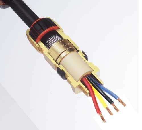
14 Entry Thread Ø 'A' Ø 'B' 'H' Entry Deluge Boot 'G' Approx (ompressed Length) Diaphragm Seal Armour/Braid '' able Gland Type 50/453/Universal ATEX Flameproof and Increased Safety Ref. Os O A B D E F Entry Thread ½" ½" ¾"/½" M5 "/¾" M3 ¼"/" M40 ½"/¼" M50 M63 M75 NPT* Std./ Option "/½" ½"/" 3"/½" Thread Length 'H' Larger cable glands available in 50/453 design. See page 3. G M80 3½" # H M90 3½" # J M00 4" # Smaller value is applicable when selecting reduced NPT entry option. s Os and O are available with an M6 thread size. For O size with M6 thread, the maximum cable inner sheath diameter is 0.9mm. Os F size metric entry threads are.5mm pitch as standard. For G size cable glands and above, a mm pitch is supplied as standard (.5mm pitch with mm length of thread can be supplied) please specifiy when ordering. General Information All dimensions in millimetres (except* where dimensions are in inches). # Dedicated armour clamping rings are fitted. Please specify armour type and size. Assembly instruction data sheet No. A.I For sizes Os to F. Assembly instruction data sheet No. A.I. 39. For sizes G to J. Alternative Reversible Armour lamping Rings (RA) O/Os A B D E F SELETION TABLE Steel Wire Armour/Braid/Tape Orientation Orientation Accessories including locknuts, sealing washers, serrated washers, earth tags, shrouds, adaptors and reducers available. See pages Materials & Finishes The 50/453/Universal cable gland is manufactured as standard in brass, stainless steel and aluminium. NPT entries, nickel plated as standard. Full nickel plating by electroplating or electroless plating is also available, as are other materials on request. able Gland Ordering Examples able Gland Type//Thread e.g. 50/453/UNIV//M3 50/453/UNIV//¼" NPT able Gland with Alternative lamping Ring (AR) ABLE GLAND SELETION TABLE Inner Sheath 'A' Min able Acceptance Details 44.4/ / /65.3 Outer Sheath 'B' Min Ref. '' Armour/Braid Orientation Orientation 0.9/.5 0/ /.5 0/ /.5 0/0.7.5/.6.6/.0.6/.0.8/.5.8/.5.8/.5 0/0.7 0/0.7 0/0.7 0/.0 0/.0 0/.0 # # # 'G' Flats Hexagon Dimensions orners Application Outdoor or Indoor use. For use with single wire armoured 'W', wire braided 'X' and steel tape armoured 'Z', elastomer and plastic insulated cables. For particular use with : ables that exhibit "old Flow" characteristics. See technical section of catalogue for installation rules and regulations. Features Provides armour clamping using one clamping arrangement for all armour/braid types. Provides a diaphragm seal on the cables inner sheath which will not damage cable that has "old Flow" characteristics. Provides an outer deluge seal to prevent moisture ingress to the cable armour/braid. Provides a cable retention and low smoke and fume, zero halogen seal onto the cables outer sheath. Flameproof EExd and Increased Safety EExe. II GD Baseefa ertificate No. BAS 0 ATEX 078X. For Os F. Baseefa ertificate No. BAS 0 ATEX 96X. For G J. Suitable for use in Zone, Zone, Zone and Zone. Suitable for use in Gas Groups IIA, IIB and II. onstruction and test standards EN 5004, EN 5008, EN 5009 and EN 508. IE , IE and IE IP66, IP67 and IP68 (30 metres for 7 days) ingress protection to IE 6059, EN 6059 and NEMA 4X. DTS0 deluge protection certified by ITS. Operating temperature range 60 to +80 as standard. Alternative ertification Options Available. Exd II/Exe II. BRExd II/Exe II. GOST RExd IIU/Exe IIU. AUSExd II/Exe II. 50/453/Universal able Gland e.g. 50/453/UNIV//M3/AR 50/453/UNIV//¼" NPT/AR 3
15 Entry Thread Ø 'A' Ø 'B' 'H' Entry 'G' Approx (ompressed Length) Armour/Braid '' able Gland Type 50/453/RA ATEX Flameproof and Increased Safety Ref. Entry Thread NPT* Std./ Option Os ½" O A B M5 M3 ½" ¾"/½" "/¾" ¼"/" M40 ½"/¼" D E F M50 M63 M75 "/½" ½"/" 3"/½" All dimensions in millimetres (except* where dimensions are in inches). # Dedicated armour clamping rings are fitted. Please specify armour type and size. Assembly instruction data sheet No. A.I. 30. For sizes Os to F. Assembly instruction data sheet No. A.I. 39. For sizes G to J. Alternative Seal (S) Min. Min. Alternative Reversible Armour lamping Rings (RA) O/Os A B D E F SELETION TABLE Steel Wire Armour/Braid/Tape Orientation Orientation Accessories including locknuts, sealing washers, serrated washers, earth tags, shrouds, adaptors and reducers available. See pages Materials & Finishes The 50/453/RA cable gland is manufactured as standard in brass, stainless steel and aluminium. NPT entries, nickel plated as standard. Full nickel plating by electroplating or electroless plating is also available, as are other materials on request. able Gland Ordering Examples able Gland Type//Thread e.g. 50/453/RA//M3 50/453/RA//¼" NPT able Gland with Alternative Seal (S) e.g. 50/453/RA//M3/S 50/453/RA//¼" NPT/S ABLE GLAND SELETION TABLE Thread Length 'H' Min. able Acceptance Details Inner Sheath 'A' Standard Seal Outer Sheath 'B' / / / Ref. '' Armour/Braid Orientation Orientation /.5 0/ /.5 0/ /.5 0/ /.6.6/.0.6/.0.8/.5.8/.5.8/.5 0/0.7 0/0.7 0/0.7 0/.0 0/.0 0/.0 'G' Flats Hexagon Dimensions able Gland with Alternative lamping Ring (AR) e.g. 50/453/RA//M3/AR 50/453/RA//¼" NPT/AR orners Larger cable glands available in 50/453 design. See page 3. G M80 3½" # # H M90 3½" # # J M00 4" # # Smaller value is applicable when selecting reduced NPT entry option. s Os and O are available with an M6 thread size. For O size with M6 thread, the maximum cable inner sheath diameter is 0.9mm. Os F size metric entry threads are.5mm pitch as standard. For G size cable glands and above, a mm pitch is supplied as standard (.5mm pitch with mm length of thread can be supplied) please specifiy when ordering General Information Application Outdoor or Indoor use. For use with single wire armoured 'W', wire braided 'X' and steel tape armoured 'Z', elastomer and plastic insulated cables. See technical section of catalogue for installation rules and regulations. Features Provides armour clamping using one clamping arrangement for all armour/ braid types. Provides a seal on the cables inner sheath. Deluge protection option available. Provides a cable retention and low smoke and fume, zero halogen seal onto the cables outer sheath. Flameproof EExd and Increased Safety EExe. II GD Baseefa ertificate No. BAS 0 ATEX 07X. For Os F. Baseefa ertificate No. BAS 0 ATEX 96X. For G J. Suitable for use in Zone, Zone, Zone and Zone. Suitable for use in Gas Groups IIA, IIB and II. onstruction and test standards EN 5004, EN 5008, EN 5009 and EN 508. IE , IE and IE IP66, IP67 and IP68 (30 metres for 7 days) ingress protection to IE 6059, EN 6059 and NEMA 4X. DTS0 deluge protection certified by ITS. Operating temperature range 60 to +80 as standard. Alternative ertification Options Available. Exd II/Exe II. BRExd II/Exe II. GOST RExd IIU/Exe IIU. AUSExd II/Exe II. 50/453/RA able Gland 4
16 Entry Thr ea d Ø 'A' Ø 'B' 'H' Entry Lead Sheath Bond 'G' Approx (ompressed Length) Armour/Braid '' able Gland Type 50/453/RA/L For Lead Sheath ables ATEX Flameproof and Increased Safety Entry Thread Ref. NPT* Std./ Option O A B D E F M5 M3 M40 M50 M63 M75 ½" ¾"/½" "/¾" ¼"/" ½"/¼" "/½" ½"/" 3"/½" Thread Length 'H' Larger cable glands available in 50/453/L design. See page 3. G M80 3½" H M90 3½" J M00 4" Smaller value is applicable when selecting reduced NPT entry option. O is available with an M6 thread size. For O size with M6 thread, the maximum cable inner sheath diameter is 0.9mm. O F size metric entry threads are.5mm pitch as standard. For G size cable glands and above, a mm pitch is supplied as standard (.5mm pitch with mm length of thread can be supplied) please specifiy when ordering. Alternative Reversible Armour lamping Rings (RA) All dimensions in millimetres (except* where dimensions are in inches). # Dedicated armour clamping rings are fitted. Please specify armour type and size. Assembly instruction data sheet No. A.I For sizes O to F. Assembly instruction data sheet No. A.I For sizes G to J. ABLE GLAND SELETION TABLE Min General Information able Acceptance Details Inner Lead Sheath 'A' Outer Alternative Sheath (K) Seal+Bond 'B' Min. Min. Standard (L) Seal+Bond / / /64.3 O/Os A B D E F SELETION TABLE SteelWire Armour/Braid/Tape Orientation Orientation Accessories including locknuts, sealing washers, serrated washers, earth tags, shrouds, adaptors and reducers available. See pages Materials & Finishes The 50/453/RA/L cable gland is manufactured as standard in brass, stainless steel and aluminium. NPT entries, nickel plated as standard. Full nickel plating available. able Gland Ordering Examples able Gland Type//Thread/ Standard Inner Seal + Bond e.g. 50/453/RA//M3/L 50/453/RA//¼" NPT/L able Gland with Alternative Inner Seal + Bond e.g. 50/453/RA//M3/K 50/453/RA//¼" NPT/K Ref. '' Armour/Braid Orientation 0.9/.5 0.9/.5.5/.6.6/.0.6/.0.8/.5.8/.5.8/.5 # # # Orientation 0/0.7 0/0.7 0/0.7 0/0.7 0/0.7 0/.0 0/.0 0/.0 # # # 'G' Flats Hexagon Dimensions able Gland with Alternative lamping Ring (AR) orners e.g. 50/453/RA//M3/L/AR 50/453/RA//¼" NPT/L/AR Application Outdoor or Indoor use. For use with single wire armoured 'W', wire braided 'X' and steel tape armoured 'Z', elastomer and plastic insulated cables with a lead inner sheath. See technical section of catalogue for installation rules and regulations. Features Provides armour clamping using one clamping arrangement for all armour/braid types. Provides a seal and an electrical bond on the cables lead inner sheath. Deluge protection option available. Provides a cable retention and low smoke and fume, zero halogen seal onto the cables outer sheath. Flameproof EExd and Increased Safety EExe. II GD Baseefa ertificate No. BAS 0 ATEX 07X. For O F. Baseefa ertificate No. BAS 0 ATEX 96X. For G J. Suitable for use in Zone, Zone, Zone and Zone. Suitable for use in Gas Groups IIA, IIB and II. onstruction and test standards EN 5004, EN 5008, EN 5009 and EN 508. IE , IE and IE IP66, IP67 and IP68 (30 metres for 7 days) ingress protection to IE 6059, EN 6059 and NEMA 4X. DTS0 deluge protection certified by ITS. Operating temperature range 60 to +80 as standard. Alternative ertification Options Available. Exd II/Exe II. BRExd II/Exe II. GOST RExd IIU/Exe IIU. 5 0/453/RA /L able Glan d
17 Entry Thread Ø 'B'.0mm Entry 'G' Approx (ompressed Length) Armour/Braid '' able Gland Type PSG 553/RA ATEX Flameproof and Increased Safety Ref. A B M5 M3 ABLE GLAND SELETION TABLE Entry Thread NPT* Std./ Option ¾"/½" "/¾" ¼"/" Min. All entry threads are.5mm pitch medium fit. All dimensions in millimetres (except* where dimensions are in inches). Assembly instruction data sheet No. A.I. 3. Accessories including locknuts, sealing washers, serrated washers, earth tags, shrouds, adaptors and reducers available. See pages Materials & Finishes The PSG 553/RA cable gland is manufactured as standard in brass, stainless steel and aluminium. NPT entries, nickel plated as standard. Full nickel plating by electroplating or electroless plating is also available, as are other materials on request. able Gland Ordering Examples able Gland Type//Thread e.g. PSG 553/RA//M3 PSG 553/RA//¼" NPT Punch Tool Ordering Example e.g. Punch Tool Number. able Acceptance Details Outer Sheath 'B' '' Armour/Braid Orientation Orientation 0.9/.5 0/0.7.5/.6 0/0.7.6/.0 0/0.7 'G' Hexagon Dimensions Flats orners ABLE GLAND SIZE FOR ORE SIZE & NUMBER Maximum No. of ores Punch Ref. ore.s.a. mm².5.5 A & B General Information ores ross Sectional Area mm² A & B B & No. No. No B PUNH TOOL SIZE DETAILS B Application Outdoor or Indoor use. For use with single wire armoured 'W', wire braided 'X' and steel tape armoured 'Z', elastomer and plastic insulated cables. For particular use with : a) ables that are not effectively filled, compact and/or circular, have tape bedding or have hygroscopic fillers. b) ables that exhibit "old Flow" characteristics. c) Enclosures for gas group II, under litres in volume and containing an ignition source. d) Enclosures for gas groups IIA or IIB, which are greater than litres in volume and contain an ignition source. See technical section of the catalogue for installation rules and regulations. Features Provides a barrier seal to the individual insulated cores within the cable and prevents entry of the products of an explosion into the cable. The required number of holes for the cores are punched in the seal by means of a special tool to suit the core size. Provides armour clamping using one clamping arrangement for all armour/ braid types. Deluge protection option available. Provides a cable retention and low smoke and fume, zero halogen seal onto the cables outer sheath. Flameproof EExd and Increased Safety EExe. II GD Baseefa ertificate No. BAS 0 ATEX 074X. Suitable for use in Zone, Zone, Zone and Zone. Suitable for use in Gas Groups IIA, IIB and II. onstruction and test standards EN 5004, EN 5008, EN 5009 and EN 508. IE , IE and IE IP66, IP67 and IP68 (30 metres for 7 days) ingress protection to IE 6059 and EN Operating temperature range 60 to +80 as standard. PSG 553/RA able Gland 6
18 Entry Thread Ø 'E' Ø 'D' Ø 'B'.0mm Entry 'G' Approx (ompressed Length) Inspectable ompound able Gland Type IG 63 ATEX Flameproof and Increased Safety Ref. Os O A B D E F Entry Thread ½" ½" ¾"/½" M5 "/¾" M3 ¼"/" M40 ½"/¼" M50 M63 M75 ABLE GLAND SELETION TABLE NPT* Std./ Option "/½" ½"/" 3"/½" able Acceptance Details Inner Sheath/ Outer Sheath 'B' ores Standard 'D' 'E' Seal Over ores Inner Sheath 66./65.3 No. Of ores All entry threads are.5mm pitch medium fit. All dimensions in millimetres (except* where dimensions are in inches). Two part sealing compound and assembly instructions are supplied with the cable gland. Assembly instruction data sheet No. A.I Accessories including locknuts, sealing washers, serrated washers, earth tags, shrouds, adaptors and reducers available. See pages Materials & Finishes The IG 63 cable gland is manufactured as standard in brass, stainless steel and aluminium. NPT entries, nickel plated as standard. Full nickel plating by electroplating or electroless plating is also available, as are other materials on request. Min Alternative Seal (S) Min Smaller value is applicable when selecting reduced NPT entry option. General Information able Gland Ordering Examples able Gland Type//Thread e.g. IG 63//M3 IG 63//¼" NPT able Gland with Alternative Seal (S) e.g. IG 63//M3/S IG 63//¼" NPT/S 'G' Hexagon Dimensions Flats orners Application Outdoor or Indoor use. For use with nonarmoured elastomer and plastic insulated cables. For particular use with : a) ables that are not effectively filled, compact and/or circular, have tape bedding or have hygroscopic fillers. b) ables that exhibit "old Flow" characteristics. c) Enclosures containing an ignition source in gas group II areas or containing an ignition source in a Zone area and exceeding litres in volume. See technical section of the catalogue for installation rules and regulations. Features Provides a barrier seal between the individual insulated cores within the cable and prevents entry of the products of an explosion into the cable. Assembly of the cable gland compresses and distributes the compound evenly to create a barrier seal at the point of entry into the enclosure. The compound chamber may be seperated from the cured compound to ensure that the chamber has been effectively filled. If required, external voids can be repaired. Provides a cable retention seal onto the cables outer sheath. Flameproof EExd and Increased Safety EExe. II GD Baseefa ertificate No. BAS 0 ATEX 079X. Suitable for use in Zone, Zone, Zone and Zone. Suitable for use in Gas Groups IIA, IIB and II. onstruction and test standards EN 5004, EN 5008, EN 5009 and EN 508. IE , IE and IE IP66, IP67 and IP68 (30 metres for 7 days) ingress protection to IE 6059, EN 6059 and NEMA 4X. DTS0 deluge protection certified by ITS. Operating temperature range 60 to +80 as standard. Alternative ertification Options Available. Exd II/Exe II. BRExd II/Exe II. AUSExd II/Exe II. IG 63 able Gland 7
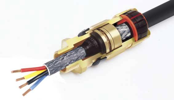
19 Entry Thread Ø 'E' Ø 'D' Ø 'B'.0mm Entry Inspectable ompound 'G' Approx (ompressed Length) Deluge Boot Armour/Braid '' able Gland Type IG 653/Universal ATEX Flameproof and Increased Safety Ref. Os O A B D E F Entry Thread ½" M5 M3 M40 M50 M63 M75 ABLE GLAND SELETION TABLE NPT* Std./ Option ½" ¾"/½" "/¾" ¼"/" ½"/¼" 6.3 Inner Sheath/ ores 'D' 'E' Over Inner ores Sheath Smaller value is applicable when selecting reduced NPT entry option. All entry threads are.5mm pitch medium fit. All dimensions in millimetres (except* where dimensions are in inches). Two part sealing compound and assembly instructions are supplied with the cable gland. Assembly instruction data sheet No. A.I. 30. able Acceptance Details No. Of ores Outer Sheath 'B' Min. Alternative Reversible Armour lamping Rings (RA) O/Os A B D E F SELETION TABLE Steel Wire Armour/Braid/Tape Orientation Orientation Accessories including locknuts, sealing washers, serrated washers, earth tags, shrouds, adaptors and reducers available. See pages Materials & Finishes The IG 653/Universal cable gland is manufactured as standard in brass, stainless steel and aluminium. NPT entries, nickel plated as standard. Full nickel plating by electroplating or electroless plating is also available, as are other materials on request "/½" ½"/" "/½" / General Information able Gland Ordering Examples able Gland Type//Thread e.g. IG 653/UNIV//M3 IG 653/UNIV//¼" NPT able Gland with Alternative lamping Ring (AR) e.g. IG 653/UNIV//M3/AR IG 653/UNIV//¼" NPT/AR Ref. '' Armour/Braid Orientation Orientation 0.9/.5 0/ / /.5.5/.6.6/.0.6/.0.8/.5.8/.5.8/.5 0/0.7 0/0.7 0/0.7 0/0.7 0/0.7 0/.0 0/.0 0/.0 'G' Hexagon Dimensions Flats orners Application Outdoor or Indoor use. For use with single wire armoured 'W', wire braided 'X' and steel tape armoured 'Z', elastomer and plastic insulated cables. For particular use with : a) ables that are not effectively filled, compact and/or circular, have tape bedding or have hygroscopic fillers. b) ables that exhibit "old Flow" characteristics. c) Enclosures containing an ignition source in gas group II areas or containing an ignition source in a Zone area. See technical section of the catalogue for installation rules and regulations. Features Provides a barrier seal between the individual insulated cores within the cable and prevents entry of the products of an explosion into the cable. Assembly of the cable gland compresses and distributes the compound evenly to create a barrier seal at the point of entry into the enclosure. The compound chamber may be seperated from the cured compound to ensure that the chamber has been effectively filled. If required, external voids can be repaired. Provides armour clamping, using one clamping arrangement for all armour/braid types. Provides an outer deluge seal to prevent moisture ingress to the cable armour/braid. Provides a cable retention and low smoke and fume, zero halogen seal onto the cables outer sheath. Flameproof EExd and Increased Safety EExe. II GD Baseefa ertificate No. BAS 0 ATEX 080X. Suitable for use in Zone, Zone, Zone and Zone. Suitable for use in Gas Groups IIA, IIB and II. onstruction and test standards EN 5004, EN 5008, EN 5009 and EN 508. IE , IE and IE IP66, IP67 and IP68 (30 metres for 7 days) ingress protection to IE 6059, EN 6059 and NEMA 4X. DTS0 deluge protection certified by ITS. Operating temperature range 60 to +80 as standard. Alternative ertification Options Available. Exd II/Exe II. BRExd II/Exe II. GOST RExd IIU/Exe IIU. AUSExd II/Exe II. IG 653/Universal able Gland 8
20 En t r y Thr ea d Ø 'E' Ø 'D' Ø 'B '.0mm Entry Inspectable ompound 'G' Approx (ompressed Length) Deluge Boot Lead Sheath Bond Armour/Braid '' able Gland Type IG 653/Universal/L ATEX For Lead Sheath ables Flameproof and Increased Safety Ref. Os O A B D E F Entry Thread ½" ½" ¾"/½" M5 "/¾" M3 ¼"/" M40 ½"/¼" M50 M63 M75 ABLE GLAND SELETION TABLE NPT* Std./ Option "/½" ½"/" 3"/½" All entry threads are.5mm pitch medium fit. All dimensions in millimetres (except* where dimensions are in inches). Two part sealing compound and assembly instructions are supplied with the cable gland. Assembly instruction data sheet No. A.I able Acceptance Details Inner Sheath/ Outer ores Sheath 'D' 'E' 'B' Over ores General Information Min. Inner Sheath Inner Sheath 0.0 No. Of ores Alternative Reversible Armour lamping Rings (RA) O/Os A B D E F SELETION TABLE SteelWire Armour/Braid/Tape Orientation Orientation Accessories including locknuts, sealing washers, serrated washers, earth tags, shrouds, adaptors and reducers available. See pages Materials & Finishes The IG 653/Universal/L cable gland is manufactured as standard in brass, stainless steel and aluminium. NPT entries, nickel plated as standard. Full nickel plating by electroplating or electroless plating is also available, as are other materials on request. able Gland Ordering Examples able Gland Type//Thread/Bond e.g. IG 653/UNIV//M3/L IG 653/UNIV//¼" NPT/L able Gland with Alternative lamping Ring (AR) e.g. IG 653/UNIV//M3/L/AR IG 653/UNIV//¼" NPT/L/AR 6 Min. Orientation Ref. '' Armour/Braid Orientation /.5 0/ /.5 0.9/.5.5/.6.6/.0.6/.0.8/.5.8/.5.8/.5 0/0.7 0/0.7 0/0.7 0/0.7 0/0.7 0/.0 0/.0 0/.0 'G' Hexagon Dimensions Flats orners Application Outdoor or Indoor use. For use with single wire armoured 'W', wire braided 'X' and steel tape armoured 'Z', elastomer and plastic insulated cables with a lead inner sheath. For particular use with : a) ables that are not effectively filled, compact and/or circular, have tape bedding or have hygroscopic fillers. b) ables that exhibit "old Flow" characteristics. c) Enclosures containing an ignition source in gas group II areas or containing an ignition source in a Zone area. See technical section of the catalogue for installation rules and regulations. Features Provides a barrier seal between the individual insulated cores within the cable and prevents entry of the products of an explosion into the cable. Assembly of the cable gland compresses and distributes the compound evenly to create a barrier seal at the point of entry into the enclosure. The compound chamber may be seperated from the cured compound to ensure that the chamber has been effectively filled. If required, external voids can be repaired. Provides armour clamping, using one clamping arrangement for all armour/braid types. Provides a seal and an electrical bond on the cables lead inner sheath. Provides an outer deluge seal to prevent moisture ingress to the cable armour/braid. Provides a cable retention and low smoke and fume, zero halogen seal onto the cables outer sheath. Flameproof EExd and Increased Safety EExe. II GD Baseefa ertificate No. BAS 0 ATEX 080X. Suitable for use in Zone, Zone, Zone and Zone. Suitable for use in Gas Groups IIA, IIB and II. onstruction and test standards EN 5004, EN 5008, EN 5009 and EN 508. IE , IE and IE IP66, IP67 and IP68 (30 metres for 7 days) ingress protection to IE 6059, EN 6059 and NEMA 4X. DTS0 deluge protection certified by ITS. Operating temperature range 60 to +80 as standard. Alternative ertification Options Available. Exd II/Exe II. BRExd II/Exe II. d Glan able sal/l r I 653/Univ e GOST RExd IIU/Exe IIU. 9
21 Male Entry Thread Ø 'B' Female Entry Thread.0mm Entry 'G' Approx (ompressed Length) able Gland Type 50/44 ATEX Flameproof and Increased Safety Ref. ABLE GLAND SELETION TABLE Male Entry Thread NPT* Std./ Option Female Entry Thread NPT # A B M5 ¾"/½" "/¾" M M3 ¼"/" M M40 ½"/¼" M D M50 "/½" M / E F M63 M75 ½"/" 3"/½" M63 M / / Smaller value is applicable when selecting reduced NPT entry option. General Information able Acceptance Details Outer Sheath 'B' Standard Alternative Seal Seal (S) Min. All entry threads are.5mm pitch medium fit. All dimensions in millimetres (except* where dimensions are in inches). Assembly instruction data sheet No. A.I. 30. # NPT female thread sizes equivalent to those shown in the table for the male thread size are available. Hexagon dimensions as shown may alter. Min. 'G' Hexagon Dimensions Flats orners Application Outdoor or Indoor use. For use with nonarmoured elastomer and plastic insulated cables installed in conduit. See technical section of the catalogue for installation rules and regulations. Features Provides a cable retention seal onto the cables outer sheath. When used in increased safety applications, this cable gland may be used with braided cable where the braid and the cables outer sheath pass into the enclosure. The braid must be suitably terminated into the enclosure. Provides female running coupler for cable gland or conduit entry. 50/44 able Gland Accessories including locknuts, sealing washers, serrated washers, earth tags, shrouds, adaptors and reducers available. See pages Materials & Finishes The 50/44 cable gland is manufactured as standard in brass, stainless steel and aluminium. NPT entries, nickel plated as standard. Full nickel plating by electroplating or electroless plating is also available, as are other materials on request. able Gland Ordering Examples able Gland Type//MaleThread/ Female Thread e.g. 50/44//M3/M3 50/44//¼" NPT/M3 able Gland with Alternative Seal (S) e.g. 50/44//M3/M3/S 50/44//¼" NPT/M3/S Flameproof EExd and Increased Safety EExe. II GD Baseefa ertificate No. BAS 0 ATEX 076X. Suitable for use in Zone, Zone, Zone and Zone. Suitable for use in Gas Groups IIA, IIB and II. onstruction and test standards EN 5004, EN 5008, EN 5009 and EN 508. IE , IE and IE IP66, IP67 and IP68 (30 metres for 7 days) ingress protection to IE 6059 and EN DTS0 deluge protection certified by ITS. Operating temperature range 60 to +00 as standard. Alternative ertification Option Available. Exd II/Exe II. 0
22 Male Entry Thread Female Entry Thread.0mm Entry 'G' Approx (ompressed Length) able Gland Type SB 474 ATEX Flameproof and Increased Safety Ref. A B ABLE GLAND SELETION TABLE Male Entry Thread M5 M3 NPT* Std./ Option ¾"/½" "/¾" ¼"/" General Information Female Entry Thread M5 M3 NPT # Hexagon Dimensions Flats orners ABLE GLAND SIZE FOR ORE SIZE & NUMBER Maximum No. of ores Punch Ref. ore.s.a. mm².5.5 A & B ores ross Sectional Area mm² All entry threads are.5mm pitch medium fit. All dimensions in millimetres (except* where dimensions are in inches). Assembly instruction data sheet No. A.I # NPT female thread sizes equivalent to those shown in the table for the male thread size are available. Hexagon dimensions as shown may alter. A & B B & No. No. No 'G' B PUNH TOOL SIZE DETAILS B Application Outdoor or Indoor use. For particular use with : a) ables that are not effectively filled, compact and/or circular, have tape bedding or have hygroscopic fillers. b) ables that exhibit "old Flow" characteristics. c) Enclosures for gas group II, under litres in volume and containing an ignition d) Enclosures for gas groups IIA or IIB, which are greater than litres in volume and contain an ignition source. See technical section of the catalogue for installation rules and regulations. Features Provides a barrier seal to the individual insulated cores within the cable and prevents entry of the products of an explosion into the cable. The required number of holes for the cores are punched in the seal by means of a special tool to suit the core size. DTS0 deluge protection certified by ITS. Provides female running coupler for cable gland or conduit entry. SB 474 able Gland Accessories including locknuts, sealing washers, serrated washers, earth tags, shrouds, adaptors and reducers available. See pages Materials & Finishes The SB 474 cable gland is manufactured as standard in brass, stainless steel and aluminium. NPT entries, nickel plated as standard. Full nickel plating by electroplating or electroless plating is also available, as are other materials on request. able Gland Ordering Examples able Gland Type//Male Thread/Female Thread e.g. SB 474//M3/M3 SB 474//¼" NPT/M3 Punch Tool Ordering Example e.g. Punch Tool Number. Technical Data Flameproof EExd and Increased Safety EExe. II GD Baseefa ertificate No. BAS 0 ATEX 077X. Suitable for use in Zone, Zone, Zone and Zone. Suitable for use in Gas Groups IIA, IIB and II. onstruction and test standards EN 5004, EN 5008, EN 5009 and EN 508. IE , IE and IE IP66, IP67 and IP68 (30 metres for 7 days) ingress protection to IE 6059 and EN Operating temperature range 60 to +80 as standard.
23 Male Entry Thread Ø 'E' Ø 'D' Female Entry Thread 'H' Entry 'G' Approx (ompressed Length) Inspectable ompound Allen Grub Screw mm A/F A.5mm A/F F able Gland Type SB 656 ATEX Flameproof and Increased Safety Ref. Male Entry Thread NPT* Std./ Option ABLE GLAND SELETION TABLE Female Entry Thread NPT # Thread Length 'H' Inner Sheath/ ores Over ores Inner Sheath A B M5 M3 ¾"/½" "/¾" ¼"/" M5 M M40 ½"/¼" M D E F M50 M63 M75 "/½" ½"/" 3"/½" M50 M63 M G M80 3½" M H M90 3½" M J M00 4" M General Information No. Of ores A F size metric entry threads are.5mm pitch as standard. For G size cable glands and above, a mm pitch is supplied as standard (.5mm pitch with mm length of thread can be supplied) please specifiy when ordering. All dimensions in millimetres (except* where dimensions are in inches). Two part sealing compound and assembly instructions are supplied with the cable gland. Assembly instruction data sheet No. A.I. 3. # NPT female thread sizes equivalent to those shown in the table for the male thread size are available. Hexagon dimensions as shown may alter. Accessories including locknuts, sealing washers, serrated washers, earth tags, shrouds, adaptors and reducers available. See pages Materials & Finishes The SB 656 cable gland is manufactured as standard in brass, stainless steel and aluminium. NPT entries, nickel plated as standard. Full nickel plating by electroplating or electroless plating is also available, as are other materials on request. able Gland Ordering Examples able Gland Type//Male Thread/Female Thread e.g. SB 656//M3/M3 SB 656//¼" NPT/M3 'D' 'E' 'G' Hexagon Dimensions Flats orners Application Outdoor or Indoor use. For use with conduit incorporating individual insulated conductors or For particular use with : a) ables that are not effectively filled, compact and/or circular, have tape bedding or have hygroscopic fillers. b) ables that exhibit "old Flow" characteristics. c) Enclosures containing an ignition source in gas group II areas or containing an ignition source in a Zone area and exceeding litres in volume. See technical section of the catalogue for installation rules and regulations. Features Provides a barrier seal between the individual insulated cores within the cable and prevents entry of the products of an explosion into the cable or conduit. Seals conductors at entry to enclosure via conduit or enables an existing cable gland to be converted to a barrier type cable gland. The device is fitted with a simple compound filled chamber which permits packing around individual insulated conductors. Assembly of the cable gland compresses and distributes the compound evenly to create a barrier seal at the point of entry into the enclosure. The compound chamber may be seperated from the cured compound to ensure that the chamber has been effectively filled. If required, external voids can be repaired. Provides female running coupler for cable gland or conduit entry. Flameproof EExd and Increased Safety EExe. II GD Baseefa ertificate No. BAS 0 ATEX 08X. Suitable for use in Zone, Zone, Zone and Zone. Suitable for use in Gas Groups IIA, IIB and II. onstruction and test standards EN 5004, EN 5008, EN 5009 and EN 508. IE , IE and IE IP66, IP67 and IP68 (30 metres for 7 days) ingress protection to IE 6059, EN 6059 and NEMA 4X. DTS0 deluge protection certified by ITS. Operating temperature range 60 to +80 as standard. Alternative ertification Options Available. Exd II/Exe II. SB 656 able Gland AUSExd II/Exe II.
24 Entry Thread Ø 'A' Ø 'B' Entry Thread Ø 'A' Ø 'B' Entry Thread Ø 'A' Ø 'B' Oversize, G, H & J able Glands ATEX Flameproof/Increased Safety and Industrial 50/453 Flameproof / Increased Safety.0mm Entry Industrial.0mm Entry 'G' Approx (ompressed Length) Armour/Braid '' 'G' Approx (ompressed Length) Armour/Braid '' 50/453 Assembly instruction data sheet No. A.I. 39. For application, features, technical data, general information, materials/finishes and cable gland ordering examples, please refer to : Page 3 (50/453/Universal). Page 4 (50/453/RA). Page (50/453/RA/L). Assembly instruction data sheet No. A.I For application, features, technical data, general information, materials/finishes and cable gland ordering examples, please refer to : Page 30 (I5/RA). Oversize G, H and J able Glands 3 Industrial.0mm Entry 'G' Approx (ompressed Length) Armour/Braid '' 3 Assembly instruction data sheet No. A.I. 39. For application, features, technical data, general information, materials/finishes and cable gland ordering examples, please refer to : Page 3 (I53/RA). Page 3 (3/RA/L). American Series able Glands 'H' (M90) cable glands are available with the exception of the 755. Please contact Hawke for details. 3
25 Entry Thread Ø 'A' Ø 'B' Entry Thread Ø 'A' Ø 'B' Entry Thread Ø 'B' Increased Safety able Glands ATEX Increased Safety Only 3 Increased Safety.0mm Entry 'G' Approx~ ~(ompressed Length) The 3cable gland is manufactured as standard in brass, stainless steel and aluminium. NPT entries, nickel plated as standard. Full nickel plating available. All of Hawke's Hazardous Area cable glands are dual certified (i.e. Flameproof and Increased Safety). The following cable glands are also available to Increased Safety certification only. 3 Assembly instruction data sheet No. A.I For sizes O s to J. Baseefa ertificate No. BAS 0 ATEX 66X. For application, features, technical data, general information, materials/finishes and cable gland ordering examples, please refer to : Page (50/4). Increased Safety able Glands 35/RA Increased Safety.0mm Entry 'G' Approx (ompressed Length) Armour/Braid '' The 35/RA cable gland is manufactured as standard in brass, stainless steel and aluminium. NPT entries, nickel plated as standard. Full nickel plating available. 35/RA Assembly instruction data sheet No. A.I For sizes Os to F. No. A.I For sizes G to J. Baseefa ertificate No. BAS 0 ATEX 68X. For application, features, technical data, general information, materials/finishes and cable gland ordering examples, please refer to : Page 4 (50/453/RA). Please note however there is no inner seal with the 35/RA. This can be seen in the diagram opposite. 353/RA Increased Safety.0mm Entry 'G' Approx (ompressed Length) Armour/Braid '' 353/RA Assembly instruction data sheet No. A.I. 30. For sizes Os to F. No. A.I. 39. For sizes G to J. Baseefa ertificate No. BAS 0 ATEX 67X. For application, features, technical data, general information, materials/finishes and cable gland ordering examples, please refer to : Page 4 (50/453/RA). The 353/RA cable gland is manufactured as standard in brass, stainless steel and aluminium. NPT entries, nickel plated as standard. Full nickel plating available. 4

26 Industrial able Glands Industrial able Glands 5
27 Industrial able Glands Industrial Industrial able Glands Features Unique Rear Sealing System This arrangement offers IP66, IP67, IP68 (30 metres for 7 days), NEMA 4X and Deluge (DTS0) Ingress Protection. The seal is manufactured from a silicone material, has LSFZH properties, is ozone and oil resistant and is suitable for use at both high and low temperatures. The Rear Sealing System covers the entire range of cable diameters without the need for special seals and the cable acceptance range is stamped on the backnut for ease of inspection. The backnut can be hand tightened, with only one further spanner turn required to ensure IP66, IP67, IP68 and NEMA 4X. The Original Reversible Armour lamp The original RA clamping system was invented by Hawke over 0 years ago and is a well established proven performer in all conditions. Simply by reversing the clamping ring, the cable gland can adjust to accomodate all types of cable armour or braid. Unlike many of our competitors the correct clamping orientation is marked clearly with a 'W', 'Z' or 'X' and backed up by the presence of a groove in the component. Hawke's RA clamping system is also fully inspectable when positioned on the cable. Inspectable Deluge Seal Hawke's inspectable deluge seal offers IP66 and IP67 sealing and is certified as 'deluge proof' by ITS in accordance with DTS0. Indeed Hawke's deluge seal is so good that it exceeds the expectations of the offshore industry by not only preventing ingress into the equipment, but also into the cable gland, which could potentially corrode the cable armour. 6
28 Entry Thread Ø 'B' Entry Thread Ø 'B' 'H' Entry 'G' Approx~ ~(ompressed Length) able Gland Type Industrial Ref. K Os O A B D E F G H J Entry Thread M6 ½" ½" ¾"/½" M5 "/¾" M3 ¼"/" M40 ½"/¼" M50 M63 M75 M80 M90 M00 ABLE GLAND SELETION TABLE NPT* Std./ Option "/½" ½"/" 3"/½" 3½" 3½" 4" Thread Length 'H' Min / / / Smaller value is applicable when selecting reduced NPT entry option. s Os and O are available with an M6 thread size. For O size with M6 thread, the maximum cable outer sheath diameter is 0.9mm. K F size metric entry threads are.5mm pitch as standard. For G size cable glands and above, a mm pitch is supplied as standard (.5mm pitch with mm length of thread can be supplied) please specifiy when ordering. General Information able Acceptance Details Outer Sheath 'B' Standard Alternative Seal Seal (S) Min All dimensions in millimetres (except* where dimensions are in inches). Assembly instruction data sheet No. A.I Accessories including locknuts, sealing washers, serrated washers, earth tags, shrouds, adaptors and reducers available. See pages 'G' Hexagon Dimensions Flats orners mm Application Outdoor or Indoor use. For use with nonarmoured elastomer and plastic insulated cables. See technical section of the catalogue for installation rules and regulations. Features 'G' Approx (ompressed Length) K able Gland Design Provides a cable retention seal onto the cables outer sheath. onstruction and test standards EN 506. BS 6 Part. Type A. IP66, IP67 and IP68 (30 metres for 7 days) ingress protection to IE 6059 and EN DTS0 deluge protection certified by ITS. Operating temperature range 60 to +00 as standard. able Gland Materials & Finishes The cable gland is manufactured as standard in brass, stainless steel and aluminium. NPT entries, nickel plated as standard. Full nickel plating by electroplating or electroless plating is also available, as are other materials on request. able Gland Ordering Examples able Gland Type//Thread e.g. //M3 //¼" NPT able Gland with Alternative Seal (S) e.g. //M3/S //¼" NPT/S 7
29 Entry Thread Ø 'B' 'H' Entry 'G' Approx (ompressed Length) able Gland Type 3 Industrial Ref. Os O A B D E F G H J Entry Thread M50 M63 M75 M80 M90 M00 NPT* Std./ Option ½"/" 3"/½" 3½" 3½" 4" ABLE GLAND SELETION TABLE Thread Length 'H' ½".0 M5 M3 M40 ½" ¾"/½" "/¾" ¼"/" ½"/¼" "/½" / / / Smaller value is applicable when selecting reduced NPT entry option. s Os and O are available with an M6 thread size. For O size with M6 thread, the maximum cable outer sheath diameter is 0.9mm. Os F size metric entry threads are.5mm pitch as standard. For G size cable glands and above, a mm pitch is supplied as standard (.5mm pitch with mm length of thread can be supplied) please specifiy when ordering. General Information Min able Acceptance Details Outer Sheath 'B' Standard Alternative Seal Seal (S) Min All dimensions in millimetres (except* where dimensions are in inches). Assembly instruction data sheet No. A.I Accessories including locknuts, sealing washers, serrated washers, earth tags, shrouds, adaptors and reducers available. See pages 'G' Hexagon Dimensions Flats orners Application Outdoor or Indoor use. For use with nonarmoured elastomer and plastic insulated cables. May be used on cables incorporating inner and outer cable sheaths. See technical section of catalogue for installation rules and regulations. Features Provides a cable retention seal onto the cables outer sheath at two independent sealing points. onstruction and test standards EN 506. BS 6 Part. Type A. IP66, IP67 and IP68 (30 metres for 7 days) ingress protection to IE 6059 and EN DTS0 deluge protection certified by ITS. Operating temperature range 60 to +00 as standard. 3 able Gland Materials & Finishes The 3 cable gland is manufactured as standard in brass, stainless steel and aluminium. NPT entries, nickel plated as standard. Full nickel plating by electroplating or electroless plating is also available, as are other materials on request. able Gland Ordering Examples able Gland Type//Thread e.g. 3//M3 3//¼" NPT able Gland with Alternative Seal (S) e.g. 3//M3/S 3//¼" NPT/S 8
30 Entry Thread Ø 'A' Ø 'B'.0mm Entry 'G' Approx (ompressed Length) Armour/Braid '' able Gland Type 0/RA Industrial Ref. O A B D E F Entry Thread M5 M3 M40 M50 M63 M75 ½" ¾"/½" "/¾" ¼"/" ½"/¼" NPT* Std./ Option "/½" ½"/" 3"/½" ABLE GLAND SELETION TABLE Inner Sheath 'A' Smaller value is applicable when selecting reduced NPT entry option. O is available with an M6 thread size. For O size with M6 thread, the maximum cable inner sheath diameter is 0.9mm. General Information All entry threads are.5mm pitch medium fit. All dimensions in millimetres (except* where dimensions are in inches). Assembly instruction data sheet No. A.I. 35. Accessories including locknuts, sealing washers, serrated washers, earth tags, shrouds, adaptors and reducers available. See pages / / /65.3 able Acceptance Details Outer Sheath 'B' Alternative Reversible Armour lamping Rings (RA) Ref. O/Os A B D E F '' Armour/Braid Orientation 0.9/.5 0.9/.5.5/.6.6/.0.6/.0.8/.5.8/.5.8/.5 Orientation 0/0.7 0/0.7 0/0.7 0/0.7 0/0.7 0/.0 0/.0 0/.0 'G' Flats SELETION TABLE Steel Wire Armour/Braid/Tape Orientation Orientation Hexagon Dimensions orners Application Outdoor or Indoor use. For use with single wire armoured 'W', wire braided 'X' and steel tape armoured 'Z', elastomer and plastic insulated cables. See technical section of catalogue for installation rules and regulations. Features Provides armour clamping using one clamping arrangement for all armour/braid types. onstruction and test standards BS 6 Part. Type BW, BX and BZ. 0/RA able Gland Materials & Finishes The 0/RA cable gland is manufactured as standard in brass, stainless steel and aluminium. NPT entries, nickel plated as standard. Full nickel plating by electroplating or electroless plating is also available, as are other materials on request. able Gland Ordering Examples able Gland Type//Thread e.g. 0/RA//M3 0/RA//¼" NPT able Gland with Alternative lamping Ring (AR) e.g. 0/RA//M3/AR 0/RA//¼" NPT/AR 9
31 Entry Thread Ø 'A' Ø 'B' 'H' Entry 'G' Approx (ompressed Length) Armour/Braid '' able Gland Type /RA Industrial Ref. Entry Thread NPT* Std./ Option Os ½" O A B M5 M3 ½" ¾"/½" "/¾" ¼"/" M40 ½"/¼" D E F M50 M63 M75 "/½" ½"/" 3"/½" Larger cable glands available in design. See page 3. G M80 3½" # H M90 3½" # J M00 4" # Smaller value is applicable when selecting reduced NPT entry option. s Os and O are available with an M6 thread size. For O size with M6 thread, the maximum cable inner sheath diameter is 0.9mm. Os F size metric entry threads are.5mm pitch as standard. For G size cable glands and above, a mm pitch is supplied as standard (.5mm pitch with mm length of thread can be supplied) please specifiy when ordering. General Information All dimensions in millimetres (except* where dimensions are in inches). # Dedicated armour clamping rings are fitted. Please specify armour type and size. Assembly instruction data sheet No. A.I For sizes Os to F. Assembly instruction data sheet No. A.I For sizes G to J. Alternative Reversible Armour lamping Rings (RA) O/Os A B D E F SELETION TABLE Steel Wire Armour/Braid/Tape Orientation Orientation Accessories including locknuts, sealing washers, serrated washers, earth tags, shrouds, adaptors and reducers available. See pages Materials & Finishes The /RA cable gland is manufactured as standard in brass, stainless steel and aluminium. NPT entries, nickel plated as standard. Full nickel plating by electroplating or electroless plating is also available, as are other materials on request. able Gland Ordering Examples able Gland Type//Thread e.g. /RA//M3 /RA//¼" NPT able Gland with Alternative lamping Ring (AR) e.g. /RA//M3/AR /RA//¼" NPT/AR ABLE GLAND SELETION TABLE Thread Length 'H' Inner Sheath 'A' / / /65.3 able Acceptance Details Outer Sheath 'B' Min Ref. '' Armour/Braid Orientation Orientation 0.9/.5 0/ /.5 0/ /.5 0/0.7.5/.6.6/.0.6/.0.8/.5.8/.5.8/.5 0/0.7 0/0.7 0/0.7 0/.0 0/.0 0/.0 # # # 'G' Flats Hexagon Dimensions orners Application Outdoor or Indoor use. For use with single wire armoured 'W', wire braided 'X' and steel tape armoured 'Z', elastomer and plastic insulated cables. See technical section of catalogue for installation rules and regulations. Features Provides armour clamping using one clamping arrangement for all armour/braid types. Deluge protection option available. Provides a cable retention and low smoke and fume, zero halogen seal onto the cables outer sheath. onstruction and test standards EN 506. BS 6 Part. Type W, X and Z. IP66 ingress protection to IE 6059 and EN Operating temperature range 60 to +80 as standard. /RA able Gland 30
32 Entry Thread Ø 'A' Ø 'B' 'H' Entry Diaphragm Seal 'G' Approx (ompressed Length) Armour/Braid '' able Gland Type 3/RA Industrial Ref. Entry Thread NPT* Std./ Option Os ½" O A B M5 M3 ½" ¾"/½" "/¾" ¼"/" M40 ½"/¼" D E F M50 M63 M75 "/½" ½"/" 3"/½" Thread Length 'H' Larger cable glands available in 3 design. See page 3. G M80 3½" # H M90 3½" # J M00 4" # Smaller value is applicable when selecting reduced NPT entry option. s Os and O are available with an M6 thread size. For O size with M6 thread, the maximum cable inner sheath diameter is 0.9mm. Os F size metric entry threads are.5mm pitch as standard. For G size cable glands and above, a mm pitch is supplied as standard (.5mm pitch with mm length of thread can be supplied) please specifiy when ordering. Alternative Reversible Armour lamping Rings (RA) General Information All dimensions in millimetres (except* where dimensions are in inches). # Dedicated armour clamping rings are fitted. Please specify armour type and size. Assembly instruction data sheet No. A.I. 3. For sizes Os to F. Assembly instruction data sheet No. A.I. 39. For sizes G to J. O/Os A B D E F SELETION TABLE Steel Wire Armour/Braid/Tape Orientation Orientation Accessories including locknuts, sealing washers, serrated washers, earth tags, shrouds, adaptors and reducers available. See pages Materials & Finishes The 3/RA cable gland is manufactured as standard in brass, stainless steel and aluminium. NPT entries, nickel plated as standard. Full nickel plating by electroplating or electroless plating is also available, as are other materials on request. able Gland Ordering Examples able Gland Type//Thread e.g. 3/RA//M3 3/RA//¼" NPT able Gland with Alternative lamping Ring (AR) e.g. 3/RA//M3/AR 3/RA//¼" NPT/AR ABLE GLAND SELETION TABLE Inner Sheath 'A' Min / /65.3 able Acceptance Details Outer Sheath 'B' Min Ref. '' Armour/Braid Orientation Orientation 0.9/.5 0/ /.5 0/ /.5 0/0.7.5/.6.6/.0.6/.0.8/.5.8/.5.8/.5 0/0.7 0/0.7 0/0.7 0/.0 0/.0 0/.0 # # # 'G' Flats Hexagon Dimensions orners Application Outdoor or Indoor use. For use with single wire armoured 'W', wire braided 'X' and steel tape armoured 'Z', elastomer and plastic insulated cables. Suitable for use with cables that exhibit "old Flow" characteristics. See technical section of catalogue for installation rules and regulations. Features Provides armour clamping using one clamping arrangement for all armour/braid types. Provides a diaphragm seal on the cables inner sheath. A diaphragm seal will not damage cable that that has "old Flow" characteristics. Deluge protection option available. Provides a cable retention and low smoke and fume, zero halogen seal onto the cables outer sheath. onstruction and test standards EN 506. BS 6 Part. Type EW, EX and EZ. IP66 and IP67 ingress protection to IE 6059, EN 6059 and NEMA 4X. Operating temperature range 60 to +80 as standard. 3/RA able Gland 3
33 Entry Thr ea d Ø 'A' Ø 'B' 'H' Entry Lead Sheath Bond 'G' Approx (ompressed Length) Armour/Braid '' able Gland Type 3/RA/L For Lead Sheath ables Industrial Ref. O A B D E F Entry Thread M5 M3 M40 M50 M63 M75 NPT* Std./ Option ½" ¾"/½" "/¾" ¼"/" ½"/¼" "/½" ½"/" 3"/½" ABLE GLAND SELETION TABLE Thread Length 'H' Min. able Acceptance Details Inner Lead Sheath 'A' Outer Alternative Sheath (K) Seal+Bond 'B' Min. Min. Standard (L) Seal+Bond Larger cable glands available in 3/L design. See page 3. G M80 3½" H M90 3½" J M00 4" Smaller value is applicable when selecting the option NPT entry thread. O is available with an M6 thread size. For O size with M6 thread, the maximum cable inner sheath diameter is 0.9mm. O F size metric entry threads are.5mm pitch as standard. For G size cable glands and above, a mm pitch is supplied as standard (.5mm pitch with mm length of thread can be supplied) please specifiy when ordering. General Information / / / All dimensions in millimetres (except* where dimensions are in inches). # Dedicated armour clamping rings are fitted. Please specify armour type and size. Assembly instruction data sheet No. A.I For sizes O to F. Assembly instruction data sheet No. A.I For sizes G to J. Alternative Reversible Armour lamping Rings (RA) O/Os A B D E F Accessories including locknuts, sealing washers, serrated washers, earth tags, shrouds, adaptors and reducers available. See pages SELETION TABLE SteelWire Armour/Braid/Tape Orientation Orientation Materials & Finishes The 3/RA/L cable gland is manufactured as standard in brass, stainless steel and aluminium. NPT entries, nickel plated as standard. Full nickel plating by electroplating or electroless plating is also available, as are other materials on request. able Gland Ordering Examples able Gland Type//Thread/ Standard Inner Seal + Bond Ref. '' Armour/Braid Orientation 0.9/.5 0.9/.5.5/.6.6/.0.6/.0.8/.5.8/.5.8/.5 # # # Orientation 0/0.7 0/0.7 0/0.7 0/0.7 0/0.7 0/.0 0/.0 0/.0 # # # 'G' Hexagon Dimensions Flats able Gland with Alternative lamping Ring (AR) orners Application Outdoor or Indoor use. For use with single wire armoured 'W', wire braided 'X' and steel tape armoured 'Z', elastomer and plastic insulated cables with a lead inner sheath. See technical section of catalogue for installation rules and regulations. Features Provides armour clamping using one clamping arrangement for all armour/braid types. Provides a seal and an electrical bond on the cables lead inner sheath. Deluge protection option available. Provides a cable retention and low smoke and fume, zero halogen seal onto the cables outer sheath. d Glan able 53/RA /L onstruction and test standards EN 506. BS 6 Part. Type EW, EX and EZ. IP66, IP67 and IP68 (30 metres for 7 days) ingress protection to IE 6059, EN 6059 and NEMA 4X. Operating temperature range 60 to +80 as standard. e.g. 3/RA//M3/L 3/RA//¼" NPT/L able Gland with Alternative Inner Seal + Bond e.g. 3/RA//M3/L/AR 3/RA//¼" NPT/L/AR e.g. 3/RA//M3/K 3/RA//¼" NPT/K 3
34 Male Entry Thread Ø 'B' Female Entry Thread.0mm Entry 'G' Approx (ompressed Length) able Gland Type 4 Industrial Ref. A B D E F M5 M3 M40 M50 M63 M75 ABLE GLAND SELETION TABLE Male Entry Thread NPT* Std./ Option ¾"/½" "/¾" ¼"/" ½"/¼" "/½" ½"/" 3"/½" Female Entry Thread NPT # M5 M3 M40 M50 M63 M75 Smaller value is applicable when selecting reduced NPT entry option. General Information able Acceptance Details Outer Sheath 'B' Standard Alternative Seal Seal (S) Min / / /65.3 All entry threads are.5mm pitch medium fit. All dimensions in millimetres (except* where dimensions are in inches). Assembly instruction data sheet No. A.I. 30. # NPT female thread sizes equivalent to those shown in the table for the male thread size are available. Hexagon dimensions as shown may alter. Min Accessories including locknuts, sealing washers, serrated washers, earth tags, shrouds, adaptors and reducers available. See pages 'G' Hexagon Dimensions Flats orners Application Outdoor or Indoor use. For use with nonarmoured elastomer and plastic insulated cables installed in conduit. See technical section of the catalogue for installation rules and regulations. Features Provides a cable retention seal onto the cables outer sheath. Provides female running coupler for cable gland or conduit entry. onstruction and test standards EN 506. IP66, IP67 and IP68 (30 metres for 7 days) ingress protection to IE 6059 and EN Operating temperature range 60 to +00 as standard. 4 able Gland Materials & Finishes The 4 cable gland is manufactured as standard in brass, stainless steel and aluminium. NPT entries, nickel plated as standard. Full nickel plating by electroplating or electroless plating is also available, as are other materials on request. able Gland Ordering Examples able Gland Type//MaleThread/Female Thread e.g. 4//M3/M3 4//¼" NPT/M3 able Gland with Alternative Seal (S) e.g. 4//M3/M3/S 4//¼" NPT/M3/S 33
35 Hawke able Glands Flameproof/Increased Safety and Industrial Hawke able Glands 34

36 North American Series able Glands/onnectors North American Series able Glands/onnectors 35
, NEMA 4X and Deluge (DTS0) Ingress Protection.")
37 North American Series able Glands/onnectors Explosion Proof and General Purpose North American Series able Glands/onnectors Features Unique Rear Sealing System This arrangement offers IP66, IP67, IP68 (30 metres for 7 days), NEMA 4X and Deluge (DTS0) Ingress Protection. The seal is manufactured from a silicone material, has LSFZH properties, is ozone and oil resistant and is suitable for use at both high and low temperatures. The Rear Sealing System covers the entire range of cable diameters without the need for special seals and the cable acceptance range is stamped on the backnut for ease of inspection. The backnut can be hand tightened, with only one further spanner turn required to ensure IP66, IP67, IP68 and NEMA 4X. Armour Grounding Device This device provides 360 armour grounding which is fully inspectable. The grounding device is unique in that it remains in contact with the metal cable jacket when the cable gland/connector is disassembled for inspection. Inspectable Deluge Seal Hawke's inspectable deluge seal offers IP66 and IP67 sealing and is certified as 'deluge proof' by ITS in accordance with DTS0. Indeed Hawke's deluge seal is so good that it exceeds the expectations of the offshore industry by not only preventing ingress into the equipment, but also into the cable gland/connector, which could potentially corrode the cable armour. The deluge seal is coloured red for hazardous location products and black for industrial general purpose products. 36
38 Entry Thread Ø 'E' Ø 'D' Ø 'B' ompound 'G' Approx (ompressed Length) able Gland/onnector Type 70 Explosion Proof ABLE GLAND/ONNETOR SELETION TABLE Ref. Os O A B D E H Entry Thread NPT Std./ Option ½" ½" ½"/¾" ¾"/" "/¼" ¼"/½" "/½" ½"/" 3"/½" 3½" * M5 M3 M40 M50 M63 M90 able Acceptance Details Inner Jacket/ores 'D' Over ores 0.35" 0.35" 0.43" 0.64" 0.86".04".46".88".3" 'E' Inner Jacket No. Of ores Outer Jacket 'B' s Os and O are available with an M6 thread size. For O size with M6 thread, the maximum cable inner sheath diameter is 0.43". General Information All dimensions in inches (except* where dimensions are in millimetres). Os F size metric entry threads are.5mm pitch as standard with mm length of thread. For G size cable glands and above, a mm pitch is supplied as standard with a 0mm length of thread (.5mm pitch with mm length of thread can be supplied) please specifiy when ordering. Two part sealing compound and assembly instructions are supplied with the cable gland/connector. Assembly instruction data sheet No. A.I. 36. For sizes Os to F. Assembly instruction data sheet No. A.I For size H. Accessories including locknuts, sealing washers, serrated washers, earth tags, shrouds, adaptors and reducers available. See pages Materials & Finishes 0.39" " 0.64" 0.93".3".59".96".55" F M75.98" 0 'H' size cable gland/connector available. ontact Hawke for further details. The 70 cable gland/connector is manufactured as standard in brass, stainless steel and aluminum. NPT entries, nickel plated as standard. Full nickel plating by electroplating or electroless plating is also available, as are other materials on request Min. 0.66" 0.87".0".4".8".4".0".30".6".07".57" 3.07" 'G' 0." 0.47".8" 0.37" 0.63".8" 0.49" 0.8".84".95" 3." 3.6" 3.36" 3.56" 3.76" Hexagon Dimensions Flats 0.94" 0.94".8".4".8".7".56" 3." 3.74" orners.09".09".36".64".09".50".96" 3.64" 4.3".79" 3." 3.07" 3.5" 3.54" 4.8" 4.84" Application Outdoor or Indoor use. For use with nonarmoured cable, as permitted by the NE. See technical section of the catalogue for installation rules and regulations. Features Provides a barrier seal between the individual insulated conductors within the cable and prevents entry of the products of an explosion into the cable. Assembly of the cable gland/connector compresses and distributes the compound evenly to effect a barrier seal at the point of entry into the enclosure. Provides an outer deluge seal to prevent moisture ingress to the cable armour and enclosure. Deluge seal is coloured red to indicate Hazardous Locations product. Provides a cable retention and low smoke and fume, zero halogen seal onto the cables outer jacket. UL Listed for use in lass, Division, Gas Groups A, B, and D. UL Listed for use in lass, Zone, Gas Groups IIA, IIB and II. UL listed AExd II and AExe II lass, Zone. onstruction and test standards UL Listed hazardous locations in USA and anada. E IP66, IP67 and IP68 (30 metres for 7 days) ingress protection to IE 6059, EN6059 and NEMA 4X. DTS0 deluge tested by ITS. Operating temperature range 50 to +60 as standard. 70 able Gland/onnector able Gland/onnector Ordering Examples able Gland/onnector Type//Thread e.g. 70//" NPT 37
39 Entry Thread Ø 'E' Ø 'D' Ø 'B' Nickel Plated Hub ompound 'G' Approx (ompressed Length) Deluge Boot Armour Grounding Device able Gland/onnector Type 7 lass Division Explosion Proof ABLE GLAND/ONNETOR SELETION TABLE Ref. A B D E F H Entry Thread NPT Std./ Option ½"/¾" ¾"/" "/¼" ¼"/½" "/½" ½"/" 3"/½" 3½" * M5 M3 M40 M50 M63 M75 All dimensions in inches (except* where dimensions are in millimetres). A F size metric entry threads are.5mm pitch as standard with mm length of thread. For G size cable glands and above, a mm pitch is supplied as standard with a 0mm length of thread (.5mm pitch with mm length of thread can be supplied) please specifiy when ordering. Two part sealing compound and assembly instructions are supplied with the cable gland/connector. Assembly instruction data sheet No. A.I. 37. For sizes A to F. Assembly instruction data sheet No. A.I For size H. Accessories including locknuts, sealing washers, serrated washers, earth tags, shrouds, adaptors and reducers available. See pages able Gland/onnector Ordering Examples able Gland/onnector Type//Thread e.g. 7//" NPT 'D' able Acceptance Details Inner Jacket/ores Over ores 0.43" 0.64" 0.86".04".46".88".3" General Information Materials & Finishes Armour Jacket 'E' Min. 0.4" 0.49" 0.85".7".37".76".9" 0.64" 0.93".3".59".96".55" No. Of ores " 0 'H' size cable gland/connector available. ontact Hawke for further details. Outer Jacket 'B' Min. 0.49" 0.66" 0.87".0".4".8".4" 0.8".0".30".6".07".57" 3.07" 'G'.74".95" 3.04" 3.09" 3.37" 3.65" 3.73" Hexagon Dimensions Flats.8".4".8".7".56" 3." 3.74" The 7 cable gland/connector is manufactured as standard in brass, stainless steel and aluminum. NPT entries, nickel plated as standard. Full nickel plating by electroplating or electroless plating is also available, as are other materials on request. orners.36".64".09".50".96" 3.64" 4.3" M90.79".93" 3.47" " 3.5" 4.33" 4.8" 4.84" Application Outdoor or Indoor use. For use with continuous corrugated aluminum, Metal lad (MHL) cable. See technical section of the catalogue for installation rules and regulations. Features Provides 360 armour grounding which is fully inspectable. Grounding Device remains in contact with cable when disassembled for inspection. Provides a barrier seal between the individual insulated cores within the cable and prevents entry of the products of an explosion into the cable. Assembly of the cable gland/connector compresses and distributes the compound evenly to create a barrier seal at the point of entry into the enclosure. Provides an outer deluge seal to prevent moisture ingress to the cable armour and enclosure. Deluge seal is coloured red to indicate Hazardous Location product. Provides a cable retention and low smoke and fume, zero halogen seal onto the cables outer jacket. UL Listed for use in lass, Division, Gas Groups A, B, and D. UL Listed for use in lass, Zone, Gas Groups IIA, IIB and II. UL Listed AExd II and AExe II lass, Zone. onstruction and test standards UL Listed hazardous locations in USA and anada. E84940 IP66, IP67 and IP68 (30 metres for 7 days) ingress protection to IE 6059, EN6059 and NEMA 4X. DTS0 deluge tested by ITS. Operating temperature range 50 to +60 as standard. 7 able Gland/onnector For lass, Division M cable applications, the 73 cable gland/connector is available. Details and sizes are the same as the 7. 38
40 Entry Thread Ø 'E' Ø 'D' Ø 'B' Nickel Plated Hub ompound 'G' Approx (ompressed Length) Braid '' able Gland/onnector Type 753 MARINE Explosion Proof ABLE GLAND/ONNETOR SELETION TABLE Ref. Os O A B D E F H Entry Thread NPT Std./ Option ½" ½" ½"/¾" ¾"/" "/¼" ¼"/½" "/½" ½"/" 3"/½" 3½" * M5 M3 M40 M50 M63 M75 M90 'D' Over ores 0.35" 0.35" 0.43" 0.64" 0.86".04".46".88" able Acceptance Details Inner Jacket/ Outer ores Jacket 'E' 'B' Inner Jacket No. Of ores Smaller value is applicable when selecting reduced NPT entry option. s Os and O are available with an M6 thread size. For O size with M6 thread, the maximum cable inner sheath diameter is 0.43". General Information Min. All dimensions in inches (except* where dimensions are in millimetres). Os F size metric entry threads are.5mm pitch as standard with mm length of thread. For G size cable glands and above, a mm pitch is supplied as standard with a 0mm length of thread (.5mm pitch with mm length of thread can be supplied) please specifiy when ordering. Two part sealing compound and assembly instructions are supplied with the cable gland/connector. Assembly instruction data sheet No. A.I. 38. For sizes Os to F. Assembly instruction data sheet No. A.I For size H. Accessories including locknuts, sealing washers, serrated washers, earth tags, shrouds, adaptors and reducers available. See pages Materials & Finishes 0.7" 0.97".6".64"." able Gland/onnector Ordering Examples able Gland/onnector Type//Thread 00.8".57".3".6"/.57" 0.4" 3.07" 'H' size cable gland/connector available. ontact Hawke for further details. 'G' Hexagon Dimensions Flats orners.79" 3.05" 3.07" 3.5" 0.008"/0.03" 3.54" 4.8" 4.84" '' Braid 0.46" 6 0." 0.47" 0.008"/0.03".80" 0.94".09" 0.46" 0.49" " 0.63" 0.49" 0.8" 0.008"/0.03".80" 0.008"/0.03".83" 0.94".8".09".36" 0.66".0" 0.008"/0.03".94".4" ".30".0".6".4".07" 0.008"/0.03" 3.0" 0.008"/0.03" 3.6" 0.008"/0.03" 3.35".8".7".56" 0.008"/0.03" 3.56" 3." 0.008"/0.03" 3.76" 3.74" The 753 cable gland/connector is manufactured as standard in brass, stainless steel and aluminum. NPT entries, nickel plated as standard. Full nickel plating by electroplating or electroless plating is also available, as are other materials on request..64".09".50".96" 3.64" 4.3" Application Outdoor or Indoor use. For use with braid armoured marine shipboard jacketed or nonjacketed cable. See technical section of the catalogue for installation rules and regulations. Features Provides a barrier seal between the individual insulated conductors within the cable and prevents entry of the products of an explosion into the cable. Assembly of the cable gland/connector compresses and distributes the compound evenly to effect a barrier seal at the point of entry into the enclosure. Provides an outer deluge seal to prevent moisture ingress to the cable armour and enclosure. Deluge seal is coloured red to indicate Hazardous Location product. Provides a cable retention and low smoke and fume, zero halogen seal onto the cables outer jacket. UL Listed for use in lass, Division, Gas Groups A, B, and D. UL Listed for use in lass, Zone and Zone, Gas Groups IIA, IIB and II. UL Listed AExd II and AExe II lass, Zone. onstruction and test standards MARINE UL Listed hazardous locations in USA and anada. E8494. IP66, IP67 and IP68 (30 metres for 7 days) ingress protection to IE 6059, EN6059 and NEMA 4X. DTS0 deluge tested by ITS. Operating temperature range 50 to +60 as standard. 753 able Gland/onnector e.g. 753//" NPT 39
41 Entry Thread Ø 'E' Ø 'D' Ø 'B' Nickel Plated Hub ompound 'G' Approx (ompressed Length) Armour '' able Gland/onnector Type 755 Explosion Proof Ref. Os O A B D E F Entry Thread NPT Std./ Option ½" ½" ½"/¾" ¾"/" "/¼" ¼"/½" "/½" ½"/" 3"/½" * M5 M3 M40 M50 M63 M75 Smaller value is applicable when selecting reduced NPT entry option. s Os and O are available with an M6 thread size. For O size with M6 thread, the maximum cable inner sheath diameter is 0.43". All dimensions in inches (except* where dimensions are in millimetres). All entry threads are.5mm pitch medium fit. Two part sealing compound and assembly instructions are supplied with the cable gland/connector. Assembly instruction data sheet No. A.I. 39. Accessories including locknuts, sealing washers, serrated washers, earth tags, shrouds, adaptors and reducers available. See pages able Gland/onnector Ordering Examples able Gland/onnector Type//Thread e.g. 755//" NPT ABLE GLAND/ONNETOR SELETION TABLE 'D' Over ores 0.35" 0.35" 0.43" 0.64" 0.86".04".46".88" General Information Materials & Finishes Inner Jacket/ ores 'E' Inner Jacket 0.7" 0.97".6".64".".3".6"/.57" No. Of ores Outer Jacket 'B' Min. 0.66" 0.87".0".4".8".4" able Acceptance Details 0.46" 6 0." 0.47" 0.46" " 0.63" 0.49" " 0.8".0".30".6".07".57" 3.07" Steel Wire Armour 0.036"/0.049" 0.036"/0.049" 0.036"/0.049" 0.049"/0.06" 0.06"/0.078" 0.06"/0.078" 0.078"/0.098" 0.098" 0.098" The 755 cable gland/connector is manufactured as standard in brass, stainless steel and aluminum. NPT entries, nickel plated as standard. Full nickel plating by electroplating or electroless plating is also available, as are other materials on request '' Braid 0.008"/0.03" 0.008"/0.03" 0.008"/0.03" 0.008"/0.03" 0.008"/0.03" 0.008"/0.03" 0.008"/0.03" 0.008"/0.03" 0.008"/0.03" Tape 0.008"/0.03" 0.008"/0.03" 0.008"/0.03" 0.008"/0.039" 0.008"/0.055" 0.008"/0.070" 0.008"/0.070" 0.008"/0.070" 0.008"/0.070" 'G'.80".80".83".94" 3.0" 3.6" 3.35" 3.56" 3.76" Hexagon Dimensions Flats 0.94" 0.94".8".4".8".7".56" 3." 3.74" orners.09".09".36".64".09".50".96" 3.64" 4.3" 755 able Gland/onnector Application Outdoor or Indoor use. For use with armoured jacketed cable, as permitted by the NE. See technical section of the catalogue for installation rules and regulations. Features Provides a barrier seal between the individual insulated conductors within the cable and prevents entry of the products of an explosion into the cable. Assembly of the cable gland/connector compresses and distributes the compound evenly to effect a barrier seal at the point of entry into the enclosure. Provides an outer deluge seal to prevent moisture ingress to the cable armour and enclosure. Deluge seal is coloured red to indicate Hazardous Location product. Provides a cable retention and low smoke and fume, zero halogen seal onto the cables outer jacket. UL Listed for use in lass, Division, Gas Groups A, B, and D. UL Listed for use in lass, Zone, Gas Groups IIA, IIB and II. UL Listed AExd II and AExe II lass, Zone. onstruction and test standards UL Listed hazardous locations in USA and anada. E IP66, IP67 and IP68 (30 metres for 7 days) ingress protection to IE 6059, EN6059 and NEMA 4X. DTS0 deluge tested by ITS. Operating temperature range 50 to +60 as standard. 40
42 Entry Thread Ø 'A' Ø 'B' 'G' Approx (ompressed Length) Braid '' able Gland/onnector Type 3/X General Purpose Ref. Os Entry Thread NPT Std./ Option ½" O ½" A ½"/¾" B ¾"/" M5 "/¼" M3 ¼"/½" M40 D "/½" M50 E ½"/" M63 F 3"/½" M75 ABLE GLAND/ONNETOR SELETION TABLE * Min. 0." 0.30" 0.44" 0.5" 0.75" 0.99".4".68"." Standard Seal 'H' size cable gland/connector available. ontact Hawke for further details. H 3½" M90 able Acceptance Details Inner Jacket'A' Alternative Seal (S) 0.3" 0.46" 0.56" 0.79".04".7".74"/.67"."/.4".68"/.57" Smaller value is applicable when selecting reduced NPT entry option. s Os and O are available with an M6 thread size. For O size with M6 thread, the maximum cable inner sheath diameter is 0.43". Os F size metric entry threads are.5mm pitch as standard with mm length of thread. For G size cable glands and above, a mm pitch is supplied as standard with a 0mm length of thread (.5mm pitch with mm length of thread can be supplied) please specifiy when ordering. General Information Min. 0.34" 0.38" 0.6" 0.87".09".54".9" 0.5" 0.60" 0.83".0".37".83".9" Outer Jacket 'B' Min. 0." 0.47" 0.37" 0.63" 0.49" 0.66" 0.87".0".4".8".4" 0.8".0".30".6".07".57" 3.07" All dimensions in inches (except* where dimensions are in millimetres). Assembly instruction data sheet No. A.I. 34. Accessories including locknuts, sealing washers, serrated washers, earth tags, shrouds, adaptors and reducers available. See pages Materials & Finishes 'G' Hexagon Dimensions Flats orners.64" 3.06".96" 3.5" 0.008"/0.03" 4.8" 4.53" 5.3" The 3/X cable gland/connector is manufactured as standard in brass, stainless steel and aluminum. NPT entries, nickel plated as standard. Full nickel plating by electroplating or electroless plating is also available, as are other materials on request. '' Braid 0.008"/0.03" 0.008"/0.03" 0.008"/0.03" 0.008"/0.03" 0.008"/0.03" 0.008"/0.03" 0.008"/0.03" 0.008"/0.03" 0.008"/0.03".56".56".60".8".96" 3.04" 3.54" 3.8" 3.78".8".4".8".7".56" 3." 3.74" Application Outdoor or Indoor use. For use with armoured marine shipboard jacketed or nonjacketed cable. See technical section of the catalogue for installation rules and regulations. Features 0.94".09" 0.94".09".36".64".09".50".96" 3.64" 4.3" Provides armour clamping for marine shipboard cable. Provide a seal on the cables inner jacket. Provides an outer deluge seal to prevent moisture ingress to the cable armour and enclosure. Provides a cable retention and low smoke and fume, zero halogen seal onto the cables outer jacket. 3/X able Gland/onnector able Gland/onnector Ordering Examples able Gland/onnector Type//Thread e.g. 3/X/M3 3/X/" NPT able Gland/onnector with Alternative Seal (S) e.g. 3/X/M3/S 3/X/" NPT/S onstruction and test standards UL Listed wet locations. E833. IP66, IP67 and IP68 (30 metres for 7 days) ingress protection to IE 6059, EN6059 and NEMA 4X. DTS0 deluge tested by ITS. Operating temperature range 50 to +60 as standard. 4
43 Entry Thread Ø 'E' Ø 'B' Nickel Plated Hub Armour Stop Deluge Boot 'G' Approx (ompressed Length) Armour Grounding Device able Gland/onnector Type 70 General Purpose ABLE GLAND/ONNETOR SELETION TABLE Entry Thread able Acceptance Details Hexagon Dimensions Ref. A B D E F NPT Std./ Option ½"/¾" ¾"/" "/¼" ¼"/½" "/½" ½"/" 3"/½" * M5 M3 M40 M50 M63 M75 Armour Jacket 'E' Min. 0.4" 0.49" 0.85".7".37".76".9" General Information Outer Jacket 'B' Min. All dimensions in inches (except* where dimensions are in millimetres). A F size metric entry threads are.5mm pitch as standard with mm length of thread. For G size cable glands and above, a mm pitch is supplied as standard with a 0mm length of thread (.5mm pitch with mm length of thread can be supplied) please specifiy when ordering. Assembly instruction data sheet No. A.I. 3. For sizes A to F. Assembly instruction data sheet No. A.I. 34. For size H. Accessories including locknuts, sealing washers, serrated washers, earth tags, shrouds, adaptors and reducers available. See pages Materials & Finishes 0.64" 0.93".3".59".96".55".98" 0.49" 0.66" 0.87".0".4".8".4" 'H' size cable gland/connector available. ontact Hawke for further details. H 0.8".0".30".6".07".57" 3.07" 'G'.74".95" 3.04" 3.09" 3.37" 3.65" 3.73" Flats.8".4".8".7".56" 3." 3.74" orners.36".64".09".50".96" 3.64" 4.3" 3½" M90.93" 3.47" 3.07" 3.5" 4.33" 4.8" 4.84" The 70 cable gland/connector is manufactured as standard in brass, stainless steel and aluminum. NPT entries, nickel plated as standard. Full nickel plating by electroplating or electroless plating is also available, as are other materials on request. Application Outdoor or Indoor use. For use with continuous corrugated aluminum and interlocked steel Metal lad, MHL and Teck type cables. See technical section of the catalogue for installation rules and regulations. Features Provides 360 armour grounding which is fully inspectable. Grounding Device remains in contact with cable when disassembled for inspection. Provides an outer deluge seal to prevent moisture ingress to the cable armour and enclosure. Provides a cable retention and low smoke and fume, zero halogen seal onto the cables outer jacket. onstruction and test standards UL Listed wet locations. E IP66 and IP67 ingress protection to IE 6059, EN6059 and NEMA 4X. DTS0 deluge tested by ITS. Operating temperature range 50 to +60 as standard. 70 able Gland/onnector able Gland/onnector Ordering Examples able Gland/onnector Type//Thread e.g. 70//" NPT 4

44 Accessories Accessories 43
45 able Gland Accessories Nylon Sealing Washer Retaining 'Pips' 'V' Red Fibre Washer 'V' 'U' 'U' able Gland 'V' M5 M3 M40 M50 M63 M75 M80 M90 M00 SEALING WASHER SELETION TABLE NPT * able Gland 'V' ½" ¾" " ¼" ½" " ½" 3" 3½" 3½" 4" 'U' Application For use on cable gland entry threads. Features To maintain ingress protection rating at the enclosure. Retaining 'Pips' make washer captive on metric cable gland entry thread. Ordering Examples Sealing Washer Type// Thread e.g. Nylon Washer/M5 Fibre Washer/M5 able Gland Accessories General Information All dimensions in millimetres (except* where dimensions are in inches). Hawke does not recommend the use of tapered entry threads in enclosures with plain clearance holes. Parallel threaded entries are recommended for this purpose. Washers for M80, M90 and M00 sizes are only available in Red Fibre. Serrated Washer 'V' General Information 'U' able Gland 'V' M5 M3 M40 M50 M63 M75 SERRATED WASHER SELETION TABLE NPT * able Gland 'V' All dimensions in millimetres (except* where dimensions are in inches). Hawke does not recommend the use of tapered entry threads in enclosures with plain clearance holes. Parallel threaded entries are recommended for this purpose. ½" ¾" " ¼" ½" " ½" 3" 'U' Application For use on cable gland entry threads. Features To dampen vibrations of the cable gland/ equipment assembly which may loosen the cable gland or locknut. Materials & Finishes Hawke serrated washers are manufactured as standard in stainless steel. Ordering Examples Serrated Washer//Thread e.g. Serrated Washer/M5 Serrated Washer/" NPT 44
46 able Gland Accessories Earth Tags 'W' 'X' Ø'U' Ø'Y' 'Z' EARTH TAG SELETION TABLE able Gland 'U' M5 M3 M40 M50 M63 M75 M80 M90 M00 'Y' 'W' 'X' 'Z' Features Provides an earth bond attachment for a cable gland. Materials & Finishes Hawke earth tags are manufactured as standard in brass. Stainless Steel locknuts are available, but dimensions may differ slightly to those stated in the selection table. Please contact Hawke for details. Ordering Example Earth Tag //Thread e.g. Earth Tag/M5 able Gland Accessories General Information All dimensions in millimetres. Hawke does not recommend the use of tapered entry threads in enclosures with plain clearance holes. Parallel threaded entries are recommended for this purpose. Alternative Shape may be supplied dependant upon size. Heavy Duty Locknuts 'X' Ø'Y' General Information 'Z' able Gland M6 M5 M3 M40 M50 M63 M75 M80 M90 M00 LOKNUT SELETION TABLE x.5mm Pitch NPT Flats NPT * Flats orners 'Z' able orners 'X' 'Y' Gland 'X' 'Y' 'Z' ½" ¾" " ¼" ½" " ½" " ½" ½" " All dimensions in millimetres (except* where dimensions are in inches). Hawke does not recommend the use of tapered entry threads in enclosures with plain clearance holes. Parallel threaded entries are recommended for this purpose. Features Secures a cable gland in position at the equipment. Materials & Finishes Hawke heavy duty locknuts are manufactured as standard in brass. Stainless Steel locknuts are available, but dimensions may differ slightly to those stated in the selection table. Please contact Hawke for details. Ordering Example Locknut //Thread e.g. Locknut/M5 45
47 Male Entry Thread Female Thread Flats able Gland Accessories Flameproof, Increased Safety and Industrial PV Shrouds PP Shrouds SHROUD SELETION TABLE Ref. # O/Os A B D E F G H J Application Outdoor or Indoor use. For fitting over cable glands when additional environmental and corrosion protection is required. Materials & Finishes Hawke shrouds are supplied in black as standard. Ordering Examples Shroud Type/ e.g. PV Shroud/ PP Shroud/ able Gland Accessories Insulated Adaptor Types 478, 378 and 78 'Z'.0mm Entry 50mm INSULATED ADAPTOR SELETION TABLE Male Thread Female Thread Type Thread # Ref. NPT * Std./Option ¾"/½" "/¾" ¼"/" ½"/¼" "/½" ½"/" 3"/½" General Information All dimensions in millimetres (except* where dimensions are in inches). # Female NPT threads available. Please contact Hawke for details. A B D E F M5 M3 M40 M50 M63 M75 M5 M3 M40 M50 M63 M75 Materials & Finishes Insulated portion manufactured from glass filled nylon. Female insert and entry component are manufactured as standard in brass. 'Z' Bore Hexagon Dimensions Flats orners Application Outdoor or Indoor use. Provides electrical insulation between a cable gland or a conduit fitting and an electrical enclosure. e.g. to provide a means of isolating armour/braid on signal/instrument cable. 478 ertification and Approval Baseefa ertificate No. BAS 5U. Exd II. Suitable for use in Zone and Zone. Suitable for use in Gas Groups IIA, IIB and II. 378 ertification and Approval Baseefa ertificate No. Ex 8367U. EExe II. Suitable for use in Zone and Zone. 78 Industrial Ordering Example Insulated Adaptor//Male Thread/Female Thread e.g. 478//M3/M3 46
48 able Gland Accessories ATEX Type 475 and 477 Flameproof 'V' 475 (As shown) (477 Dimensions as 475) 477 AND 475 STOPPING PLUGS Thread x.5p NPT * M5 M3 M40 M50 M63 ¾"/½" "/¾" ¼"/" ½"/¼" "/½" ½"/" General Information M75 3"/½" All dimensions in millimetres (except* where dimensions are in inches). The 475 Flameproof EExd (removable from outside the enclosure). The 477 Flameproof EExd (removable from inside the enclosure). Materials & Finishes 475 and 477 Stopping plugs are manufactured as standard in brass. Hex. Key Flats 'V' Features To close unused cable gland entries and maintain the flameproof integrity of the equipment. Flameproof EExd II II GD IP66. Baseefa ertificate No. BAS 0 ATEX 44X. Alternative ertification Options Available. e.g. 477/M3 GOST RExd IIU/Exe IIU. AUSExd II/Exe II. Stopping Plugs Ordering Example Stopping Plug Type//Thread able Gland Accessories Type 387 Increased Safety 'V' General Information 387 STOPPING PLUGS Thread Hex. Key Flats x.5p 'V' M M5 0.0 M3 0.0 M M M M Ingress Protection To meet with IP66 and IP67, the stopping plugs must be fitted perpendicular to the equipment face in a suitably sized threaded or plain hole and the equipment face must be smooth. Plain holes must be no larger than 0.7mm above the major diameter of the stopping plug thread and the plug must be held in place with a locknut. An serrated washer may also be fitted. Type 375 Increased Safety 'V' General Information 375 STOPPING PLUGS Thread x.5p Hex. Key Flats 'V' 0. M5 0. Ingress Protection To meet with IP66 and IP67, the stopping plugs must be fitted perpendicular to the equipment face in a suitably sized threaded or plain hole and the equipment face must be smooth. Plain holes must be no larger than 0.7mm above the major diameter of the stopping plug thread and the plug must be held in place with a locknut. An optional serrated washer may also be fitted. Features To close unused cable gland entries and maintain the increased safety integrity of the equipment Increased Safety EExe II II GD IP66. Baseefa ertificate No. BAS 0 ATEX U. Alternative ertification Options Available. Materials & Finishes 387 Stopping plugs are manufactured as standard in brass. Stopping Plugs Ordering Example Stopping Plug Type//Thread e.g. 387/M3 Features To close unused cable gland entries and maintain the increased safety integrity of the equipment Increased Safety EExe II II GD IP66. Baseefa ertificate No. BAS 0 ATEX 04U. Alternative ertification Options Available. AUSExd II/Exe II. Materials & Finishes 375 Stopping plugs are manufactured as standard in Black Nylon. Stopping Plugs Ordering Example Stopping Plug Type//Thread e.g. 375/ AUSExd II/Exe II. 47
49 Adaptor Reducer Adaptors and Reducers Type 476 and 376 ATEX Flameproof and Increased Safety Female Thread Adaptor Reducer M6 M5 M3 M40 M50 M63 M75 ½" ¾" " ADAPTOR AND REDUER SELETION TABLE Male Thread NPT M6 M5 M3 M40 M50 M63 M75 ½" ¾" " ¼" ½" " ½" 3" Adaptors and Reducers NPT ¼" ½" " ½" 3" Application/Features Provides a means of connection between the equipment and cable glands with dissimilar thread sizes or types. Only metric female thread types are permitted by the ATEX Directive for flameproof EExd applications. Flameproof adaptors/reducers are permitted with female thread types other than metric, providing the equipment has been certified for use with the adaptor/reducer. EExe adaptors/reducers have no ATEX thread type restriction Flameproof EExd and Increased Safety EExe. II GD IP66. Baseefa ertificate No. BAS 0 ATEX 49X. Baseefa ertificate No. BAS 0 ATEX 4U (see*). (omponent approval only). Baseefa ertificate No. BAS 0 ATEX 4X (EExe II only). Suitable for use in Zone, Zone, Zone and Zone. Suitable for use in Gas Groups IIA, IIB and II. onstruction and test standards EN 5004, EN 5008, EN 5009 and EN 508. IE , IE and IE Alternative ertification Options Available. BRExd II/Exe II. GOST RExd IIU/Exe IIU. AUSExd II/Exe II. General Information All entry threads are.5mm pitch medium fit. Materials & Finishes Hawke adaptors/reducers are manufactured as standard in brass. Adaptor/Reducer Ordering Examples 476/Adaptor or Reducer/Male Thread /Female Thread. e.g. 476/R/M5/ 476/A/M5/¾" NPT. 48
50 49
51 Hawke able Glands and Enclosures The intent of this section of the catalogue is to identify important features that may be useful in the selection and installation of explosion protected electrical equipment. There are numerous different regulations, codes, guidelines and standards for the design, installation and maintenance of electrical and nonelectrical systems for use in potentially explosive atmospheres. The type of operational facility, geographic location, operator practice, local and national legislation, authority having jurisdiction etc. will determine many of the design and installation rules permitted. A fixed or floating petroleum facility located offshore, for example, would not be designed or classified in the same manner as an onshore petrochemical facility..0 Potentially Explosive Atmospheres An explosive atmosphere is defined as a mixture: Of flammable substances in the form of gases, vapours, mists, dusts or fibres With air Under atmospheric conditions In which, after ignition has occurred, combustion spreads to the entire unburned mixture.0 Area lassification (lassification of Locations) The purpose of area classification is to provide a basis for the correct selection, installation and location of electrical and nonelectrical equipment in those areas. Areas must be classified depending on the properties of the flammable vapours, liquids, gases, mists, combustible dusts or fibres that may be present and the likelihood that a flammable or combustible concentration or quantity is present. The aim of area classification is to avoid ignition of flammable releases that may occur in the operation of facilities. The intent is to reduce to an acceptable minimum level the probability of a flammable atmosphere and an ignition source occurring at the same time. 3.0 ENELE and IE 3. Area lassification Area classification is the division of a facility into threedimensional hazardous areas and nonhazardous areas and the subdivision of the hazardous area into 'Zones'. Hazardous areas may be subdivided into three Zones as follows: Flammable gases and vapours Zone 0 An area in which an explosive atmosphere is constantly present, or present for long periods. Zone Zone An area in which an explosive atmosphere is likely to occur in normal operation. (Rough Guide: 0 hours or more / year but less than,000 hours / year) An area in which an explosive atmosphere is not likely to occur in normal operation and if it occurs, it will exist only for a short time. (Rough Guide: Less than 0 hours / year) 50
52 Hawke able Glands and Enclosures ombustible Dusts Zone 0 An area in which combustible dust, as a cloud, is present continuously or frequently, during normal operation, in sufficient quantity to be capable of producing an explosive concentration of combustible dust in a mixture with air Zone Zone For further information on the classification of hazardous areas, see: IE An area, in which combustible dust, as a cloud, is occasionally present during normal operation, in a sufficient quantity to be capable of producing an explosive concentration of combustible dust in a mixture with air. An area, in which combustible dust, as a cloud, may occur infrequently and persist for only a short period, or in which accumulations of layers of combustible dust may give rise to an explosive concentration of combustible dust in mixture with air. Electrical Apparatus for Explosive Gas Atmospheres, lassification of Hazardous Areas IE 643 (Proposed hange to IE 640) IE PR EN 5083 Electrical apparatus for use in the presence of combustible dust Part 3: lassification of areas where combustible dusts are, or may be, present Electrical Apparatus for Explosive Gas Atmospheres, lassification lassification of areas where dusts are, or may be, present Institute of Petroleum Model ode of Safe Practice in the Petroleum Industry, Part : Area lassification ode for Petroleum Installations, IP 3. lassification Society A lassification Society may also enforce requirements for the design and installation of facilities. These requirements, which are in addition to statutory requirements, may influence the design and installation of the electrical systems. lassification Societies include ABS, DNV and Lloyds Register. 3.3 Design and Installation of Electrical Systems for Hazardous (lassified) Areas There are numerous regulation codes, guidelines and standards for the design, selection and installation of electrical installation in potentially explosive atmospheres. These requirements are in addition to the requirements for installations in nonhazardous areas. There are several types of protection, i.e. construction techniques, available for electrical apparatus in hazardous areas. The type of protection permitted will depend upon the applicable installation codes and rules to be adopted. The selection of electrical apparatus should be in accordance with the following: lassification of the hazardous area Temperature class or ignition temperature of the gas, liquid, vapours, mist, dust or fibre Where applicable, the gas, vapour or dust classification in relation to the group or subgroup of the electrical apparatus External influences and ambient temperature 5
53 Hawke able Glands and Enclosures 3.4 Apparatus selection according to Zones Apparatus for use in Zone 0 Intrinsic safety 'ia' Apparatus for use in Zone Electrical apparatus permitted for use in Zone 0. Flameproof enclosure 'd' Pressurised apparatus 'p' Powder filling 'q' Oil immersion 'o' Increased safety 'e' Intrinsic safety 'ib' Encapsulation 'm' Apparatus for use in Zone Electrical apparatus permitted for use in Zone 0 or Zone or Electrical apparatus designed specifically for Zone (for example type of protection 'n' or Electrical apparatus complying with the requirements of a recognised standard for industrial electrical apparatus, which does not, in normal operation, have ignition capable hot surface and does not in normal operation produce arcs or sparks. This equipment must be in an enclosure with a degree of protection and mechanical strength suitable for the environment and be assessed by a person who is familiar with the requirements of any relevant standards and codes of practice. Apparatus for use in Zones 0, and Refer to EN 508 Electrical apparatus protected by enclosures Selection, installation and maintenance. 3.5 Apparatus selection according to the ignition temperature of the gas or vapour The equipment must be selected so that its maximum surface temperature will not reach the ignition temperature of any gas or vapour that may be present. Temperature class of electrical apparatus T T T3 T4 T5 T6 Maximun surface temperature of electrical apparatus Ignition temperature of gas or vapour >450 >300 >00 >35 >00 >85 If the marking of the electrical apparatus does not include an ambient temperature range, the apparatus is only for use within an ambient temperature range from 0 to +40. For further information regarding data for flammable gases and vapours, see PD IE
54 Hawke able Glands and Enclosures 3.6 Apparatus selection according to apparatus grouping The grouping of gases and vapours are classified into Group I and Group II categories. Group I is relevant to atmospheres containing firedamp (a mixture of gases, composed mostly of methane, found underground in mines). Group II is intended for use in all other places with potentially explosive atmospheres. Group II electrical apparatus with types of protection 'd' and 'i' are further subdivided into apparatus group IIA, IIB or II. Electrical apparatus with type of protection 'n' may also be subdivided if it contains certain devices or components. Gas / Vapour Subdivision IIA (typical gas propane) IIB (typical gas ethylene) II (typical gases acetylene and hydrogen) 3.7 Apparatus onstruction Standards Apparatus subgroup permitted IIA, IIB or II IIB or II II ENELE EN 5004 EN 500 EN 5006 EN 5007 EN 5008 EN 5009 General Requirements Oil Immersion 'o' Pressurisation 'p' Powder Filling 'q' Flameproof Enclosure 'd' Increased Safety 'e' IE IE General Requirements IE Oil Immersion 'o' IE Pressurisation 'p' IE Powder Filling 'q' IE Flameproof Enclosure 'd' IE Increased Safety 'e' EN 5000 Intrinsic Safety 'i' IE Intrinsic Safety 'i' EN 500 Electrical Apparatus type 'n' IE Electrical Apparatus type 'n' EN 5008 Encapsulation 'm' IE Encapsulation 'm' 3.8 Installation Standards and odes There are numerous different regulations, codes, guidelines and standards for the design, installation and maintenance of electrical and nonelectrical systems for use in potentially explosive atmospheres. The type of operational facility, geographic location, operator practice, local and national legislation, authority having jurisdiction etc. will determine many of the design and installation rules permitted For further information on the design, selection and installation of equipment for use in hazardous areas see: IE IE 6897 IE 64 (Proposed hange to IE 644) EN EN 508 Electrical installations in hazardous areas (other than mines) Mobile and fixed offshore units Electrical installation, Part 7: Hazardous areas Electrical apparatus in the presence of combustible dust. Part : Electrical apparatus protected by enclosures and surface temperature Electrical installations in hazardous areas (other than mines) Electrical apparatus for use in the presence of combustible dust Part. Electrical apparatus protected by enclosures selection, installation and maintenance. 53
55 Hawke able Glands and Enclosures 3.9 Inspection Standards and odes For information regarding the installation and maintenance of equipment for use in hazardous see: IE Inspection and maintenance of electrical installations in hazardous areas (other than mines) IE 647 Electrical apparatus for use in the presence of combustible dust atmosphere Part 7: Inspection and maintenance 4.0 ATEX 94/9/E Directive ATEX is the term used when referring to the European Unions (EU) Directive 94/9/E The ATEX Directive main objectives are to guarantee the free circulation of goods within the European Union by aligning the technical and legal requirements of the Member States. "ATEX" is derived from the French "Atmosphères Explosibles". The Directive is named: "Approximation of the laws of the Member States concerning equipment and protective systems intended for use in potentially explosive atmospheres". The Directive covers electrical and nonelectrical equipment and protective systems intended for use in potentially explosive atmospheres in mining and surface industries. The Directive covers: equipment and products that have potential ignition sources protective systems products that control the effects of incipient explosions safety devices products that may be outside a potentially explosive atmosphere but that have an explosion safety function. components products that are intended to form parts of equipment or protective systems To ensure compliance with the Directive, equipment must meet with the essential requirements specified in the Directive and be marked with the E marking. The process of ensuring that equipment complies with the Directive, conformity assessment procedure(s) must be complied with. These procedures may involve a Notified Body. A Notified body is a body that is independent of the product manufacturer and assesses conformity of the products and the manufacturer with the Directive. The Notified Body has to be approved and appointed by its government. onformity assessment procedures include, but are not limited by: E Type examination including testing and inspection of a product design, where appropriate Production Quality Assurance including the assessment, periodic auditing, testing and inspection of production samples, where appropriate, and of the manufacturers quality system. Product Verification the inspection and/or testing of each production item for conformity with the type that was subjected to E Type Examination Internal ontrol of Production the verification by the manufacturer that the product design and each production item conform to either harmonised European Standards or the essential requirements or a combination of the two The ATEX Directive came into force on a voluntary basis on st March 996 and will become mandatory from the st July 003 and all products within its scope will have to comply before being placed on the market or put into service. 54
56 Hawke Glands and Enclosures The Directive classifies equipment into eight categories depending on the equipment's area of use: ategory M equipment intended for mining use and is required to remain functional in the presence of an explosive atmosphere. ategory M ategory G ategory G ategory 3G ategory D ategory D equipment intended for mining use but is intended to be deenergised in the event of an explosive atmosphere. nonmining equipment for use in Zone 0. nonmining equipment for use in Zone. nonmining equipment for use in Zone. nonmining equipment for use in Zone 0. nonmining equipment for use in Zone. ategory D nonmining equipment for use in Zone. 4. ATEX 37 Directive 99/9/E The Directive covers the use of equipment in potentially explosive atmospheres and its aim is to establish minimum requirements for improving the safety and health of workers. Article 37 of Directive 89/39/E was published in the official journal of the E on 8th January 000 as Directive 99/9/E, it is the th individual Directive of the framework Directive 89/39/EE. The article defines the: Obligations of the employees re. the prevention and protection against explosions Assessment obligations re. the assessment of explosion risks. General obligations re. the safety and health of worker Requirements for explosion protection documents In places where potentially explosive atmospheres may occur in such quantities as to endanger the health and safety of workers, the point of entry must be marked with the sign shown below in accordance with Section II, Article 7 of the Directive. Ex 55


57 Hawke able Glands and Enclosures 5.0 Wiring Systems able systems and accessories should be installed in positions that prevent them from being subject to mechanical damage, corrosion, chemical attack, heat and other detrimental environmental conditions. Selection of the wiring system and cable type must consider these influences and where exposure to such conditions are unavoidable, protective measures such as minimising the risk of mechanical damage by the use of appropriate armoured cable types should be considered. The connection of cables and conduits to the electrical apparatus must be in accordance with the requirements of the relevant type of protection and installation rules. 5. ENELE and IE Wiring Methods With the introduction of cables incorporating new construction materials and especially cables with fire retardant or fire resistant properties such as cables complying with IE 6033 and IE 6033, cables may exhibit "cold flow" characteristics. "old flow" is a term used for thermoplastic materials that flow when subjected to pressure at ambient temperature. These "cold flow" characteristics could have adverse effects on the protection of the apparatus. A suitable cable gland should be used that does not incorporate displacement / compression seals that act upon the part(s) of the cable having cold flow characteristics. To overcome this problem, Hawke has developed cable glands that incorporate diaphragm seals that act upon the "cold flow" cable sheath without compressing or damaging the cable. A typical cable gland incorporating displacement/compression seals and a Hawke 50/453/Universal cable gland incorporating a diaphragm seal are shown below. No cable damage due to Hawke 50/453 Universal diaphragm seal cable gland design. able damage as found with cable gland designs incorporating compression / displacement seals. The IE and ENELE installation standards, IE and EN address "cold flow" in lause
58 Hawke able Glands and Enclosures 5. Extract from EN : 997 / IE : 996 Installations in hazardous areas 9..3 onnections The connection of cables and conduits to the electrical apparatus shall be made in acordance with the requirements of the relevant type of protection. Notes: ertain types of cable employ materials which can exhibit significant "cold flow" characteristics which could have adverse effects on the protection of the apparatus. Where such cable is to be used, a suitable cable entry device should be employed, for example cable entry devices not employing compression seals which act upon the part(s) of the cable having "cold flow" characteristics. "old flow" can be more fully described as "thermoplastic materials which flow when subjected to pressure of ambient temperature". Figure Selection chart for cable entry devices into flameproof enclosures for cables complying with item b) of 0.3. It is important to read notes and 0.3. before selecting appropriate cable gland for flameproof applications from Figure below Start YES Does this enclosure contain an internal source of ignition? (see note) NO Apply 0.3. d) or e) YES YES Does the hazardous gas require II apparatus? Is the volume of the enclosure greater than dm 3? YES NO Is the area of installation Zone? NO NO Use a suitable flameproof cable entry device with a sealing ring NOTE Internal sources of ignition include sparks or equipment temperatures occurring in normal operation which can cause ignition. An enclosure containing terminals only or an indirect entry enclosure (see 0.3.) is considered not to constitute an internal source of ignition. 57
59 Hawke able Glands and Enclosures Hazardous Area Information 0.3 able Entry Systems 0.3. General It is essential that cable entry systems comply with all the requirements referred to in the appropriate apparatus standard, that the cable entry device is appropriate to the type of cable employed, maintains the respective method of protection and is in accordance with clause 9. Where cables enter into flameproof apparatus via flameproof bushings through the wall of the enclosure which are part of the apparatus (indirect entry), the parts of the bushings outside the flameproof enclosure will be protected in accordance with one of the types of protection listed in IE 790. Normally the exposed part of the bushings will be within a terminal compartment which will either be another flameproof enclosure or will be protected by protection type 'e'. Where the terminal compartment is Ex'd', then the cable system shall comply with Where the terminal compartment is Ex'e', then the cable system shall comply with.3. Where cables enter into flameproof apparatus directly, the cable system shall comply with Selection The cable entry system shall comply with one of the following: a) cable entry device in compliance with IE 79 and the particular type of cable intended for use with that device; b) thermoplastic, thermosetting or elastomeric cable which is substantially compact and circular, has extruded bedding and the fillers, if any, are nonhygroscopic, may utilize flameproof cable entry devices, incorporating a sealing ring selected in accordance with figure; c) mineral insulated cable with or without plastic outer covering with appropriate flameproof cable entry device; d) flameproof sealing device (for example a stopper box or sealing chamber) specified in the apparatus documentation or having component approval and employing cable entry devices appropriate to the cables used. The sealing devices such as stopper boxes or sealing chambers shall incorporate compound or other appropriate seals which permit stopping around indivudual cores. Sealing devices shall be fitted at the point of entry of cables to the apparatus; e) flameproof cable entry devices incorporating compound filled seals around the individual cores or other equivalent sealing arrangements; f) other means which maintain the integrity of the flameproof enclosure. NOTE Where a factorymade termination of the encapsulated type is used, no attempt should be made to interfere with the connection to the apparatus or to replace the cable. 58
60 Hawke able Glands and Enclosures Hazardous Area Information.3 Wiring Systems.3. General ables and conduits shall be installed in accordance with clause 9 and the following additional requirements concerning cable entries and conductor terminations..3. able Entry Devices The connection of cables to increased safety apparatus shall be effected by means of cable entry devices appropriate to the type of cable used. They shall maintain protection type 'e' and shall incorporate a suitable sealing component to achieve IP54 degree of protection of the terminal enclosure. NOTES To meet IP 54 it may be necessary to seal between the cable and the enclosure (for example by means of a sealing washer or thread sealant. Threaded cable entry devices into threaded cable entry plates or enclosures of 6mm or greater thickness need no additional sealing between the cable entry device and the entry plate or enclosure providing the axis of the cable entry device is perpendicular to the external surface of the cable entry plate or enclosure. AKNOWLEDGEMENT Extracts from BS EN : 997 reproduced with the permission of BSI under licence no. PD/ and 90. omplete editions of the standards can be obtained by post from BSI ustomer Services, 389 jhiswick high Road, London. W4 4AL 5.3 Wiring Methods for Type of Protection 'e' Increased Safety: The cable entry device, e.g. cable gland, must comply with all the requirements referred to in the appropriate Standard, be appropriate to the cable type. and maintain the type 'e' integrity of the equipment. A minimum ingress protection rating of IP54 is required for increased safety equipment. To meet with this requirement it may be necessary to provide a seal between the cable gland and the equipment, for example, by the use of a sealing washer or thread sealant. Where cable glands are fitted into nonmetallic enclosures, metallic enclosures with a painted type finish or enclosures with nonthreaded clearance holes, additional ingress and earthing / bonding considerations may be necessary. Please refer to the sealing washer, earthtag, serrated washer and locknut accessories shown in the catalogue. 59
61 Hawke able Glands and Enclosures 6.0 Apparatus Marking IE and ENELE (Group II) 6. ATEX Marking (Glands) Manufacturer's name or registered trademark Equipment certificate issued by an EE approved body The symbol for each type of protection technique used The temperature class or maximum surface temperature in or both. (able glands need not be marked with the temperature class) HAWKE 50/453/UNIV/B/M5 Manufacturer's type identification, e.g. catalogue number The symbol to indicate that the electrical apparatus corresponds with one or more explosion protection tecuniques E Ex d II T6 Tamb The group of electrical apparatus The group subdivision, if applicable When the equipment is designed for use in an ambient temperature range other than 0 to +40, the symbol Ta or Tamb together with the special range of ambient temperatures must be marked. Year of certification Marking to indicate special conditions for safe use BAS X Name or mark of certificate testing station ertificate Number U Marking to indicate an Ex component which requires additional certification before being used in a hazardous area 6. ATEX Marking (Enclosures) The name and address of the manufacturer Type, serial number and the year in which the equipment was constructed The specific marking of explosion protection group and the category. followed by the symbol of the equipment 'EN50 04 EN50 09 EN50 8' (optional), 'EExeII' Temperature lassification, 0600, Gas and Dust Groups, Maximum Surface Temperature of the enclosure (T), IP rating, ertification Name and Number, 'DO NOT OPEN WHEN ENERGIZED'. Maximum Dissipated Power (Watts), Volts and Amps. Note: If the temperature range is outside the normal range of 0 to +40, it must be marked on the label. 60
62 Hawke able Glands and Enclosures For equipment Group II : the letter "G" where explosive atmospheres caused by gases, vapour or mists are concerned and / or the letter "D" where explosive atmospheres caused by dusts are concerned Example: Product Name / Type Temperature Range Wattage ompany Name & Address E onformity Marking Explosive Protection Temperature lass Gas and Dust Groups HAWKE INTERNATIONAL, ASHTONULYNE. OL7 0NA. UK Type PL6 T amb 60 to +40 IP66/67 DO NOT OPEN WHEN ENERGIZED Dissipated Wattage 4. Hawke Serial No W 345/0 EExeII T6 IIGD T80 BAS0ATEX07X 550 V A Licence No. Serial No. Maximum Surface Temperature (Dust Temperature) ertification Name & Number Ingress (IP) Rating Ampage Voltage Serial Number inc. Year of onstruction Marking Location for Approved Modifiers 6. Additional E Marking The E conformity marking must consist of the initials and be followed by the identification number of the notified body responsible for production control. Example:
63 Hawke able Glands and Enclosures 7.0 E Marking The E Marking is intended to facilitate the free movement of products within the European Union. By affixing E marking to products, the manufacturer is making a legal declaration that the product meets with the appropriate requirements of all relevant European Directives. E marking only applies to products within the scope of the Directives. It should not be applied to products if they are outside the 7. EM, Electromagnetic ompatibility Directive Most electrical and electronic products made or sold in the EU must: Be constructed so they do not cause excessive electromagnetic interference and are not unduly affected by electromagnetic interference; In the case of certain radiotransmitting equipment, be subject to E type examination by a notified body; and arry E marking able glands are not considered to come within the scope of the Directive, however we have carried out independent thirdparty testing on the EM shielding effectiveness of our armoured type cable glands fitted onto single wire armoured and braidedtype cables. The electromagnetic ingress between the cable sample (perfect connection) and that of the cable sample fitted with the cable gland was of such a small magnitude that it could be regarded as within acceptable uncertainty of measurement. As such, it can be concluded that the shielding effectiveness of single wire armoured or braided cable is maintained when fitted with an appropriate Hawke armoured type cable gland. 7. Low Voltage Directive The Low voltage Directive 73/3/EE embodies a number of principles: Only electrical equipment that does not jeopardise the safety of people, domestic animals and property, is permitted on the market. Only electrical equipment, that satisfies the E marking requirements of the LVD, is in compliance. Electrical equipment is not required to be tested or marked for approval by an independent third party Enforcement is the responsibility of each member state within its national jurisdiction. The regulations apply to all electrical equipment, except where extensions apply, that is designed for use between 50 and 000 volts ac or 75 and 00 volts dc. Only components, which are in themselves "electrical equipment", need satisfy the Low Voltage Directive. able glands are not in themselves "electrical equipment" and therefore do not fall within the scope of the LVD. 8.0 ertification / Listing / Approvals Electrical equipment for use in potentially explosive atmospheres is usually certified, listed or approved by a recognised ertification Body or Test House. In Europe, there are numerous ertification Bodies such as BASEEFA 00 Limited and SIRA in the UK. In North America, there are many recognised ertification Bodies and testing laboratories such as UL, FM and the SA. The definition of "Approved" by the NE is "Acceptable to the authority having jurisdiction". The definition "Listed" by the NE is "Equipment, materials or services included in a list published by an organisation that is acceptable to the authority having jurisdiction". Further information is given in the NE. 6
64 Hawke able Glands and Enclosures 9.0 ENELE and IE Degree of Protection, IP ode The standards EN 6059 and IE 6059 describe a system for classifying the degrees of protection provided by the enclosures of electrial equipment as follows : First Number Nonprotected Protection of persons against 0 access to hazardous parts inside the enclosure and against solid foreign objects Protected against objects of 50mm diameter and greater 50.5 Protected against solid foreign objects of.5mm diameter and greater An object probe, sphere of 50mm diameter, shall not fully penetrate An object probe, sphere of.5mm diameter, shall not fully penetrate Second Number Nonprotected Protection of the equipment 0 inside the enclosure against harmful effects due to the ingress of water Protected against vertically falling water drops Protected against vertically falling water drops when enclosure tilted up to Vertically falling drops shall have no harmful effects Vertically falling drops shall have no harmful effects when the enclosure is tilted at any angle up to on either side of the vertical 3 Protected against solid foreign objects of.5mm diameter and greater An object probe, sphere of.5mm diameter, shall not penetrate at all 3 Protected against spraying water Water sprayed at an angle up to 60 on either side of the vertical shall have no harmful effects 4 Protected against solid foreign objects of.0mm diameter and greater An object probe, sphere of.0mm diameter, shall not penetrate at all 4 Protected against splashing water Water splashed against the enclosure from any direction shall have no harmful effects 5 Dustprotected Ingress of dust is not totally prevented, but dust shall not penetrate in a quantity to interfere with satisfactory operation of apparatus or to impair safety 5 Protected against water jets Water projected in jets against the enclosure from any direction shall have no harmful effects 6 Dusttight No ingress of dust 6 Protected against powered water jets Water projected in powerful jets against the enclosure from any direction shall have no harmful effects Typical Designation : IP66 7 M 8 cm min. Protected against the effects of temporary immersion in water for 30 mins Protected against the effects of continuous immersion in water Ingress of water in quantities causing harmful effects shall not be possible when the enclosure is temporarily immersed in water under standardised conditions of pressure and time Ingress of water in quantities causing harmful effects shall not be possible when the enclosure is continuously immersed in water under conditions which shall be agreed between manufacturer and user but which are more severe than for numeral 7 63
65 Hawke able Glands and Enclosures The protection of the enclosure and the equipment inside against external influences or conditions, such as: mechanical impacts, corrosion, corrosive solvents, solar radiation, icing moisture (e.g. produced by condensation), and explosive atmospheres, are matters that should be dealt with by the relevant product Standard. There are additional and supplementary optional letters to the above coding; these designators are A, B, & D and H, M, S & W, and further information can be found in the relevant Standard(s). 9. Deluge Ingress Protection On offshore facilities, equipment may be located in areas subject to emergency deluge systems. Equipment that has been evaluated as certified for use in hazardous areas may not be suitable for use in these locations. A testing method for electrical equipment to be installed in areas subject to deluge systems, DTS0, has been prepared by the Explosion and Fire Hazards Group of ERA Technology (now known as ITS) in collaboration with Shell UK Exploration and Production Ltd. 0.0 IEEx Scheme Testing includes: Energising the equipment (where appropriate) for 60 minutes prior to the deluge test, then interrupting the electrical power at the start of the deluge test and resuming after 60 minutes until the completion of the deluge test. arrying out insulation resistance testing before and after preconditioning and after the deluge test, where applicable. arrying out preconditioning by exposure to vibration and thermal ageing at 90% relative humidity and at a temperature 0k above the equipments maximum service temperature and/or at least 80 of any appropriate seals. arrying out deluge test using a deluge chamber fitted with deluge nozzles that apply a salt water solution deluge pressure within the range of 3.5 bar to 4.5 bar at a water temperature in the range of 5 to 0 for 3hours. The objective of the IEEx Scheme is to facilitate international trade in electrical equipment intended for use in potentially explosive atmospheres by eliminating the need for multiple national certification. The IEEx Scheme provides a means for manufacturers to obtain ertificates of onformity that will be accepted at national level in all participating countries. A ertificate of onformity may be obtained from any certification body accepted into the scheme. The objective of the IEEx Scheme is worldwide acceptance of one standard, one certificate, and one mark. For the IE scheme to achieve its objective, every applicable national standard will need to be identical to the corresponding IE standard. A transition period will be necessary to allow time for participating IEEx Scheme countries to align their national standards with the IE standards and work towards national acceptance of IEEx ertificates of onformity and the IEEx mark..0 North American Hazardous (lassified) Locations. Area lassification Area classification is the division of a facility into a two or threedimensional hazardous location, a nonhazardous location and the subdivision of the hazardous location into 'Divisions' or 'Zones'. Hazardous (classified) locations may be subdivided as follows: 64
66 Hawke able Glands and Enclosures In the United States of America, hazardous (classified) locations are subdivided into three Zones or two Divisions, as follows: lass, Flammable Gases, Vapors or Liquids Division : Where ignitable concentrations of flammable gases, vapors or liquids can exist all of the time or some time under normal operating conditions. lass, Flammable Gases, Vapors or Liquids Zone 0: Where ignitable concentrations of flammable gases, vapors or liquids can exist all of the time or for long periods at time under normal operation conditions. Zone : Where ignitable concentrations of flammable gases, vapors or liquids can exist some of the time under normal operating conditions. Division : Where ignitable concentrations of flammable gases, vapors or liquids are not likely to exist under normal operating conditions Zone : Where ignitable concentrations of flammable gases, vapors or liquids are not likely to exist under normal operating conditions. lass, ombustible Dusts Division : Where ignitable concentrations of flammable gases, vapors or liquids can exist all of the time or some time under normal operating Division : Where ignitable concentrations of combustible dusts are not likely to exist under normal operating conditions There is no Zone classification for dusts, fibres or flyings at present in the NE lass, Ignitable Fibres and Flyings Division : Where ignitable concentrations of ignitable fibres and flyings can exist all of the time or some of the time under normal operating conditions Division : Where ignitable concentrations of ignitable fibres and flyings are not likely to exist under normal operating conditions 65
67 Hawke able Glands and Enclosures For further information on the classification of hazardous (classified) locations see: NE, NFPA 70 National Electric ode, NFPA 70 NFPA 30 Flammable and ombustible Liquids ode NFPA 497 Recommended Practice for the lassification of Flammable Liquids, Gases or Vapours and of Hazardous (lassified) Locations for Electrical Installations in hemical Process Areas NFPA 499 Recommended Practice for the lassification of ombustible Dusts and of Hazardous (lassified) Locations for Electrical Installations in hemical Process Areas ANSI/API RP500 Recommended Practice for lassification of Locations for Electrical Installations at Petroleum Facilities lassified as lass I, Division and Division ANSI/API RP 505 lassification of Locations for Electrical Installations at Petroleum Facilities lassified as lass I, Zone 0, Zone or Zone. Apparatus selection according to lass Apparatus for use in lass, Division Explosionproof Intrinsically safe Purged / pressurised (type X or Y) Apparatus for use in lass, Division Any lass, Division method Nonincendive Nonsparking device Purged / pressurised (type Z) Hermetically sealed Oil immersion Apparatus for use in lass, Zone 0 Intrinsic safety AEx ia lass I, Division intrinsically safe Apparatus for use in lass, Zone Any lass I, Zone 0 method Any lass I, Division method Flameproof, AEx d Increased safety, AEx e Intrinsic safety, AEx ib Purged pressurised, AEx p Powder filling, AEx q Oil immersion, AEx o Encapsulation, AEx m Apparatus for use in lass, Zone Any lass I, Zone 0 or method Any lass I, Division or method Type of protection AEx n Intrinsically safe equipment listed for use in lass I, Division, locations for the same gas or a permitted by Section 5057(d) of the NE, and with suitable temperature rating is permitted in lass I, Zone 0 locations. Equipment approved for use in lass I, Division or listed for use in lass I, Zone 0 locations for the same gas, or as permitted by Section 5057(d) of the NE, and with a suitable temperature rating is permitted in lass I, Zone locations. Equipment approved for use in lass I, Division or Division locations for the same gas, or as permitted by Section 5057(d) of the NE, and with a suitable temperature rating is permitted in lass I, Zone locations. Equipment listed as classified for use in lass I locations is not necessarily acceptable for lass II locations as it may not be dusttight or operate at a safe temperature with a dust covering. 66
68 Hawke able Glands and Enclosures.3 Apparatus selection according to the ignition temperature of the gas or vap The equipment must be selected so that its maximum surface temperature will not reach the ignition temperature of any gas or vapor that may be present. Temperature class of electrical apparatus Maximun surface temperature of electrical apparatus Ignition temperature of gas or vapour T T TA TB T >450 >300 >80 >60 >30 TD > T3 T3A T3B 65 T3 60 T4 35 T4A 0 T5 00 T6 85 >00 >80 >65 >60 >35 >0 >00 >85 Low ambient conditions require special consideration. Explosion proof of dust ignition proof equipment may not be suitable for use at temperatures lower than 5 (3 F) unless they are identified for low temperature service. Unless the equipment is marked otherwise, it is for use only in an ambient temperature range of 5 (3 F) to +40 (+04 F). Equipment that is approved for lass I and lass II should be marked with the maximum safe operating temperature. For information regarding data for flammable gases and vapors, see NFPA 497 and NFPA Apparatus selection according to the ignition temperature of the dust The equipment must be selected so that its maximum surface temperature will be less than the ignition temperature of the specific dust. For information regarding data for dusts, see NFPA Apparatus selection according to apparatus grouping Equipment that is approved for lass I and lass II should be marked with the maximum safe operating temperature. 67
69 Hawke able Glands and Enclosures The grouping of lass I gases and vapors are classified into categories A, B, and D. Gas / Vapor Group The grouping of lass II dusts are classified into categories E, F, and G. Dust Group A (typical gas acetylene) B (typical gas hydrogen) (typical gas ethylene) D (typical gas propane) E (typical atmospheres containing combustible metal dusts) F (typical atmospheres containing coal dusts) G (typical atmospheres containing grain dusts).6 Apparatus onstruction Standards ANSI / UL 03 Explosionproof and Dustignition Proof Electrical Equipment for use in Hazardous (lassified) Locations ANSI / ISA S. Nonincendive Electrical Equipment for use in lass I and II, Division and lass III, Divisions and Hazardous (lassified) Locations. ANSI / NFPA 496 Standard for Purged and Pressurised Enclosures for Electrical Equipment. ANSI / UL 93 Intrinsically Safe Apparatus and Associated Apparatus for use in lass I, II and III, Division, Hazardous Locations. ANSI / UL 698 Industrial ontrol Equipment for use in Hazardous (lassified) Locations. ANSI / UL 5 Metallad ables and ablesealing Fittings for use in Hazardous (lassified) Locations. UL 604 Electrical Equipment for use in lass I and II, Division and lass III Hazardous (lassified) Locations. ANSI / UL 79 Electrical Equipment for use in lass I, Zone 0, and Hazardous (lassified) Locations. ISA S.0.0 Electrical Apparatus for use in lass I, Zone 0, Hazardous (lassified) Locations, General Requirements. ISA S..0 Electrical Apparatus for use in lass I, Zone and Hazardous (lassified) Locations, Type of Protection Flameproof 'd' ISA S.6.0 Electrical Apparatus for use in lass I, Zone and Hazardous (lassified) Locations, Type of Protection Increased Safety 'e'. 68
70 Hawke able Glands and Enclosures.7 Installation Standards and odes NE, NFPA 70 USG 45 FR Parts 0 3 National Electrical ode (NE) Shipping, Subhapter J, Electrical Engineering ANSI / API RP 4F API RP 4FZ.0 Wiring Systems Recommended Practice for Design and Installatin of Electrical Systems for Fixed and Floating Offshore Petroleum Facilities for Unclassified and lass, Division and Division Locations. Rcommended Practice for Design and Installation of Electrical systems for fixed and floating offshore petroleum facilities for Unclassified and lass, Zone 0, Zone and Zone Locations. able systems and accessories should be installed in positions that prevent them from being subject to mechanical damage, corrosion, chemical attack, heat and other detrimental environmental conditions. Selection of the wiring system and cable type must consider these influences and where exposure to such conditions are avoidable, protective measures such as minimising the risk of mechanical damage by the use of appropriate armoured cable types should be considered. The connection of cables and conduits to the electrical apparatus must be in accordance with the requirements of the relevant type of protection and installation rules.. National Electrical ode (NE) Wiring Methods In lass I, Division locations, the NE permits the following wiring methods: Hawke Type 7 ablegland/ onnector Type M cable, listed for use, with a gas / vapor tight continuous corrugated aluminum sheath, an overall jacket of suitable polymeric material, separate grounding conductors, in accordance with Sections 50 and 504 of the NE, and provided with termination fittings listed for he application, e.g. Hawke type 7 cable gland/connector. Type IT cable, listed for use with a gas / vapor tight continuous aluminum sheath, an overall jacket of suitable polymeric material in accordance with Section 504 of the NE and provided with termination fittings listed for the application, e.g. Hawke type 7 cable gland/connector. Threaded rigid metal conduit, threaded steel intermediate metal conduit, or type MI cable with termination fittings approved for the location and in accordance with Section 504 of All boxes, fittings and joints must be explosionproof. 69
71 Hawke able Glands and Enclosures In lass I, Division locations, the NE permits the following wiring methods: Type M, MV, IT, PLT, T or MI cable with approved termination fittings in accordance with Section 504 of the NE. Threaded rigid metal conduit, threaded steel intermediate metal conduit. Hawke Type 7 able Gland/ onnector Nonincendive field wiring using any of the methods suitable for wiring in ordinary locations in accordance with Section 504 of the NE. Boxes, fittings and joints need not be explosionproof except as required by the NE code.. able Seals, lass, Division ables must be sealed at the termination. The sealing fitting, e.g. a barrier type cable gland, must provide a seal against the passage of gas or vapours through the fitting. Type M cables with multiconductors, a gas / vapour tight continuous corrugated aluminum sheath and an overall jacket with a suitable polymeric material must be sealed with an appropriate fitting, e.g. Hawke type 7, after removing the cables jacket and all other coverings so that the sealing compound surrounds each individual insulated conductor. ables with twisted pairs and shielded cables require the removal of the shielded material or separation of the twisted pairs unless the fitting, e.g. cable gland, is an approved means which minimises the entrance of gases or vapours and prevents propagation of flame into the cable core. If the fitting complies with this requirement, there will be information provided in the fittings installation instructions detailing the means to achieve the seal. Additional testing may be required on the fitting and the style and type of cable to show compliance with the sealing requirements..3 able Seals, lass, Division ables must be sealed at the point of entrance into enclosures that require to be approved for lass I locations. A sealing fitting must comply with the above criteria given in "able Seals, lass I, Division ". Hawke Type 753 able Gland/ onnector A NRTL approved cable sealing fitting e.g. barrier type cable gland, must be fitted onto cables that enter explosionproof enclosures. Further guidance is given in Section 50(d) of the NE. A NRTL approved cable sealing fitting e.g. barrier type cable gland, must be fitted onto cables where they enter explosionproof enclosures..4 United State oast Guard Wiring Methods Electrical installations in hazardous (classified) locations must comply with the general requirements of Section 43 of the IEEE standard 45 and either the NE Articles or IE series publications. In hazardous (classified) locations, the USG 46 FR Subhapter J, permits the following wiring methods: Marine shipboard cables that are permitted for use, must meet all the requirements of either IEEE standard 45, IE and the applicable flammability requirements. ables constructed to IE must meet with the flammability requirements of IE 60333, ategory A. Metalclad (type M) cables that are permitted for use, must have a continuous corrugated gas tight, vaportight, and watertight sheath of aluminum or other suitable metal that is close fitting around the conductors and with fillers. The M cable must have an overall jacket of an impervious PV or thermoset material and be certified or listed to UL
72 Hawke able Glands and Enclosures For information on other wiring methods permitted and further information, refer to Subpart 60 of the USG 46 FR. Each cable entry into explosionprotected equipment must be made with an appropriate fitting or cable gland that maintains the integrity of the equipment..4. ables with multiconductors that enter explosionproof enclosures, must be sealed with an appropriate fitting, e.g. barrier type cable gland, after removing the cables jacket and all other coverings so that the sealing compound surrounds each individual insulated conductor. ables with twisted pairs and shielded cables require the removal of the shielded material or separation of the twisted pairs unless the fitting, e.g. barrier type cable gland, is an approved means which minimises the entrance of gases or vapours and prevents propagation of flame into the cable core. If the fitting complies with this requirement, there will be information provided in the fittings installation instructions detailing the means to achieve the seal. Additional testing may be required on the fitting, and the style and type of cable to show compliance with the sealing requirements. The equipment grounding path should be carefully considered when using Shipboard ables or type T cables, as these may not inherently provide a grounding means. The armor of Shipboard ables should be grounded but can not be used as the grounding conductor. An appropriate sized grounding conductor should be included in each cable..5 American Petroleum Institute Wiring Methods lass, Division The API RP 4F Recommended Practice for the design and installation of electrical systems for fixed and floating offshore petroleum facilities recommends the following wiring methods for hazardous (classified) locations. Type MHL metal clad cables as defined in UL 5. Armored marine shipboard cable with an overall impervious sheath over the armor, constructed in accordance with UL 309, and listed as "Shipboard able Marine" by a National Recognised Testing Laboratory (NRTL). This wiring method is a departure from the NE. Type IT cable that is NRTL listed for use in lass I, Division locations with a gas / vapor tight continuous corrugated aluminum sheath and with an overall PV or other suitable polymeric jacket. Threaded rigid copperfree aluminum conduit. Threaded rigid steel, hot dipped galvanized conduit, coated with PV, or other suitable material, and with the interior protected by an additional means. An NRTL approved cable sealing fitting, e.g. barrier type cable gland complying with UL 5, must be fitted onto cables where they enter explosionproof enclosures. For further information and other wiring methods acceptable for Division, refer to lause of the API RP4F. For fitting requirements of cables with multiconductors, twisted pairs or shielded conductors into explosion proof equipment. See clause.4.. 7
73 Hawke able Glands and Enclosures HawkeType 70 able Gland/ onnector lass, Division Wiring methods as recommended for use in Division. Type M cable with a gas / vapour tight continuous corrugated aluminum sheath, an overall PV or other suitable polymeric jacket, and grounding conductors in accordance with NE 50. Nonarmored marine shipboard cable, with an overall impervious jacket in accordance with UL 309 and listed as "Shipboard able Marine" by a NRTL. This wiring method is a departure from the NE. Additional wiring methods acceptable for Division include type PLT, IT, T and MV cables. It is recommended that an overall PV or other suitable polymeric material jacket is included for these cable types. For additional information, refer to lause of API RP4F. In Division I locations, all electrical equipment (except intrinsically safe systems and equipment inside purged enclosures) should be explosionproof. In Division locations, the equipment does not need to be explosionproof, except where necessary to maintain the integrity of the installation. Further information on the use of equipment is given in lause of API RP4F. An NRTL approved cable sealing fitting, e.g. barrier type cable gland complying with UL 5, must be fitted onto cables where they enter explosionproof enclosures. For fitting requirements of cables with multiconductors, twisted pairs or shielded conductors into explosion proof equipment. See clause.4.. lass, Zones 0, and The API RP 4 FZ, Recommended Practice for the design and installation of electrical systems for fixed and floating offshore petroleum facilities for unclassified and lass I, Zone 0, Zone and Zone locations, recommends the following wiring methods for hazardous (classified) locations. lass, Zone Type MHL metal clad cables as defined in UL 5. Armored marine shipboard cable with an overall impervious sheath over the armor, constructed in accordance with UL 309, and listed as "Shipboard able Marine" by a National Recognised Testing Laboratory (NRTL). This wiring method is a departure from the NE. Type IT cable that is NRTL listed for use in lass, Division locations with a gas / vapor tight continuous corrugated aluminum sheath and with an overall PV or other suitable polymeric jacket. Threaded rigid copperfree aluminum conduit. Threaded rigid steel, hot dipped galvanized conduit, coated with PV, or other suitable material, and with the interior protected by an additional means. Nonarmored marine shipboard cable, with an overall impervious jacket in accordance with UL 309 and listed as "Shipboard able Marine" by a NRTL. This wiring method is a departure from the NE. For further information and other wiring methods acceptable for Zone, refer to lause of the API RP4FZ. For fitting requirements of cables with multiconductors, twisted pairs or shielded conductors into explosion proof equipment. See clause.4.. 7
74 Hawke able Glands and Enclosures lass, Zone Wiring methods as recommended for use in Zone. Type M cable with a gas / vapor tight continuous corrugated aluminum sheath, an overall PV or other suitable polymeric jacket, and grounding conductors in accordance with NE 50. Nonarmored marine shipboard cable, with an overall impervious jacket in accordance with UL 309 and listed as "Shipboard able Marine" by a NRTL. This wiring method is a departure from the NE. Additional wiring methods acceptable for Zone include type PLT, IT, T and MV cables. It is recommended that an overall PV or other suitable polymeric material jacket is included for these cable types. For additional information, refer to lause of API RP4FZ. Further information on the use of equipment is given in lause of API RP4FZ. An NRTL approved cable sealing fitting, e.g. barrier type cable gland complying with UL 5, must be fitted onto cables where they enter explosionproof enclosures. For fitting requirements of cables with multiconductors, twisted pairs or shielded conductors into explosion proof equipment. See clause.4.. Where cables enter equipment which is permitted for use in Zone or unclassified areas and that is not explosionproof, a suitable cable fitting e.g. cable gland design, need not be explosionproof, except when necessary to maintain the integrity of the enclosure and as required by the Recommended Practice. In unclassified and Zone locations, when the metallic sheath is approved as a grounding conductor, the continuous metal sheath of the M cable or the combined metallic sheath and grounding conductors may be used as the grounding conductor when used with termination fittings that are NRTL listed to UL 54B..6 National Electrical ode (NE) Zone Equipment Marking Equipment that is listed for use in lass I, Zones as permitted by the NE, should be marked as follows: lass I, Zone 0 or lass I, Zone or lass I, Zone. Applicable gas classification group(s) Temperature classification Symbol for equipment built Example: to American Standards Area lassification Temperature lassification lass, Zone AEx T6 Types of Protection able Glands/onnectors and Enclosures can be shown as 'd' or 'e'??.7 National Electrical ode (NE) Division Equipment Marking lass I or lass II or lass III or a combination of where appropriate. Gas lassification Groups able Glands/onnectors will be shown as 'IIB' Enclosures will be shown as 'II' Equipment that is approved for use in lass I, lass II or lass III, Division or as permitted by the NE, may be marked as follows: Division or Division equipment not marked to indicate a Division or marked Division is suitable for both Division and locations as defined in the NE. Group classification. Operating temperature or temperature range or as permitted by the NE. 73
75 Hawke able Glands and Enclosures.8 North American Ingress Protection NonHazardous Locations NEMA Enclosure Type Number 3 3R 3S 4 4X 5 6 6P K 3 Application For indoor use to provide a degree of protection (personnel against incidental contact with the enclosed equipment) against falling dirt. For indoor use to provide a degree of protection (personnel against incidental contact with the enclosed equipment) against falling dirt, and to provide a degree of protection against dripping and light splashing of liquids. For either indoor or outdoor use to provide a degree of protection (personnel against incidental contact with the enclosed equipment) against falling dirt, rain, sleet, snow, and windblown dust; and that will be undamaged by the external formation of ice on the enclosure. For either indoor or outdoor use to provide a degree of protection (personnel against incidental contact with the enclosed equipment) against falling dirt, rain, sleet, and snow; and that will be undamaged by the external formation of ice on the enclosure. For either indoor or outdoor use to provide a degree of protection (personnel against incidental contact with the enclosed equipment) against falling dirt, rain, sleet, snow, and windblown dust; and in which the external mechanism(s) remain operable when ice laden. For either indoor or outdoor use to provide a degree of protection (personnel against incidental contact with the enclosed equipment) against falling dirt, rain, sleet, snow, windblown dust, splashing water, and hosedirected water; and that will be undamaged by the external formation of ice on the enclosure. For either indoor or outdoor use to provide a degree of protection (personnel against incidental contact with the enclosed equipment) against falling dirt, rain, sleet, snow, windblown dust, splashing water, hosedirected water, and corrosion; and that will be undamaged by the external formation of ice on the enclosure. For either indoor or outdoor use to provide a degree of protection (personnel against incidental contact with the enclosed equipment) against falling dirt; against settling airborne dust, lint, fibres, and flyings; and to provide a degree of protection against dripping and light splashing of liquids. For either indoor or outdoor use to provide a degree of protection (personnel against incidental contact with the enclosed equipment) against falling dirt; against hosedirected water and the entry of water during occasional temporary submersion at a limited depth; and that will be undamaged by the external formation of ice on the enclosure. For either indoor or outdoor use to provide a degree of protection (personnel against incidental contact with the enclosed equipment) against falling dirt; against hosedirected water and the entry of water during prolonged submersion at a limited depth; and that will be undamaged by the external formation of ice on the enclosure. Enclosures constructed (without knockouts) for indoor use to provide a degree of protection (personnel against incidental contact with the enclosed equipment) against falling dirt; against circulating dust, lint, fibres, and flyings; and against dripping and light Enclosures constructed (without knockouts) for indoor use to provide a degree of protection (personnel against incidental contact with the enclosed equipment) against falling dirt; against circulating dust, lint, fibres, and flyings; and against dripping and light splashing of liquids. For either indoor or outdoor use to provide a degree of protection (personnel against incidental contact with the enclosed equipment) against falling dirt; against circulating dust, lint fibres, and flyings; and against the spraying, splashing, and seepage of water, oil, and noncorrosive coolants. 74
76 Hawke able Glands and Enclosures Hazardous Locations Enclosure Type Number Application For indoor use in hazardous locations classified as lass I, Division, Groups A, B,, or D as defined in NFPA 70. For indoor use in hazardous locations classified as lass II, Division, Groups E, F, or G as defined in NFPA 70. For indoor use in hazardous locations classified as lass II, Division, Groups E, F, or G as defined in NFPA 70. Further information can be found in NEMA Standard Publication 50 and UL 50 Standard Publication. The enclosures are designed to protect and to provide additional protection as stated below: NEMA Enclosure Type Number IE and ENELE R 3S 4 and 4X 5 6 and 6P IP0 IP IP54 IP4 IP54 IP56 IP5 IP67 The IE and ENELE 6059 Standards and NEMA degrees of protection can not be fully compared as equivalent ratings. The NEMA Standard includes tests for environmental conditions such as mechanical damage, corrosion, rusting, ice formation, etc. 3.0 Abbreviations, Acronyms and Definitions ABS AEx ANSI API ATEX American Bureau of Shipping. ABS is a ship classification society involved with establishing and administering of standards and rules for marine vessels and structures. A marking prefix for apparatus complying with one or more types of explosion protection techniques for installation in accordance with Article 505 American National Standards Institute American Petroleum Institute EU Directive 94/9/E Equipment and protective systems intended for use in potentially explosive atmospheres 75
77 Hawke able Glands and Enclosures Abbreviations, Acronyms and Definitions (cont'd) BASEEFA BASEEFA (00) Ltd E EN ENELE EPEL FR British Approvals Service for Electrical Equipment in Flammable Atmospheres. They provide a range of testing and certification services primarily related to equipment and systems intended for use in potentially explosive atmospheres. BASEEFA is a constituent of EES a branch of the Health & Safety Executive, They provide a range of testing and certification services primarily related to equipment and systems intended for use in potentially explosive atmospheres. anadian Electric ode. The E, Part, SA Standard., is a safety standard for the installation and maintenance of electrical equipment. European ommittee for Standardisation European ommittee for Electrotechnical Standardization. ENELE is a European Standards Organisation that publishes harmonised standards for the European market. ENELE comprises the National ommittees of the following countries: Austria, Belgium, Denmark, Finland, France, Germany, Greece, Iceland, Ireland, Italy, Luxembourg, Netherlands, Norway, Portugal, Spain, Sweden, Switzerland and the United Kingdom. entro de Pesquisas de Energia Electrica (Brazil). In Brazil, all electrical or electronic equipment for use in potentially explosive atmospheres should be certified by a Brazilian certification body recognised by INMETRO. EPEL is an accredited body that is able to issue relevant certification. ode of Federal Regulations old Flow SA DNV EES EEx ertain types of cable employ materials that can exhibit "cold flow" characteristics that could have adverse effects on the protection of the apparatus. Where such cable is used, a suitable cable entry device should be employed, for example cable entry devices not employing compression seals that act upon the part(s) of the cable having "cold flow" characteristics. "old flow" can be more fully described as thermoplastic materials that flow when subjected to pressure at ambient temperature. anadian Standards Association. A service they offer includes testing and certification services to US and anadian Standards, as well as international certification through agreements with other approval authorities. Det Norske Veritas Electrical Equipment ertification Service (UK). They provide a range of testing and certification services primarily related to equipment and systems intended for use in potentially explosive atmospheres. EES has two divisions, the Mining Equipment ertification Services (MES), and BASEEFA. The EES is a branch of the Health & Safety Executive, UK. A marking prefix for apparatus complying with one or more types of explosion protection techniques in accordance with ENELE standards. 76
78 Hawke able Glands and Enclosures Abbreviations, Acronyms and Definitions (cont'd) Explosionproof Flameproof FM Hazardous Areas IAD IE IEEx Increased Safety INMETRO Intrinsically Safe System Impervious Sheathed able IP ISA ISO ITS A term used to describe equipment that is capable of withstanding an explosion of a specified gas or vapour that may occur within it and preventing the ignition of a specified gas or vapour surrounding it. A type of protection of electrical apparatus in which the enclosure will withstand an internal explosion of a flammable mixture which has penetrated into the interior, without suffering damage and without causing ignition, through any joints or structural openings in the enclosure, of an external explosive atmosphere consisting of one or more of gases or vapours for which it is designed. Factory Mutual Research orporation (USA). Services they offer include the testing and approval of electrical equipment in accordance with US and international Standards. Locations where fire or explosion hazards may exist due to the presence of flammable gases, vapours, mists, ignitable fibres or dusts Association of Drilling ontractors Electrotechnical ommission. Founded in 906, the IE is the world organisation that prepares international standards for all electrical, electronic and related technologies. The membership consists of more than 50 participating countries. The aim of the IEEx Scheme is to facilitate international trade in electrical equipment intended for use in potentially explosive atmospheres by eliminating the need for multiple national certificates. A type of protection applied to electrical apparatus that does not produce arcs or sparks in normal service and under specified abnormal conditions, in which additional measures are applied so as to give increased security against the possibility of excessive temperatures and of the occurrence of arcs and sparks Instituto Nacional de Metrologia, Normalizacão Qualidade Industrial (Brazil) An assembly of interconnected items of apparatus which may comprise intrinsically safe apparatus, associated apparatus and other apparatus, and interconnecting cables in which the circuits within those parts of the system that may be exposed to explosive gas atmospheres are intrinsically safe circuits able constructed with an impervious metallic or nonmetallic overall covering that prevents the entrance of gases, moisture or vapours into the insulated conductor or cable A system of rating standard levels of Ingress Protection provided by the apparatus. The Society for Measurement and ontrol (formerly Instrument Society of America) Organisations for Standardisation. A worldwide federation of national standard bodies from 30 countries. ISO's mission is to promote the development of standardisation to facilitate international exchange of goods service. Intertek Testing Services 77
79 Hawke able Glands and Enclosures Abbreviations, Acronyms and Definitions (cont'd) Marine Shipboard able Maximum Surface Temperature M able MHL able NE NEMA NFPA OSHA PLT Potentially Explosive Atmosphere SS T UL USG Impervious sheathed armoured or nonarmoured cable constructed in accordance with UL 309/SA. No. 45, except that an overall impervious sheath is required over the armoured construction, and listed as "Shipboard able, Marine" by a Nationally Recognised Testing Laboratory (NRTL) The highest temperature of a surface accessible to a flammable mixture under conditions of operation and within the ratings of the equipment Metalclad cable as defined by NE Article 334 Metalclad cable for hazardous locations as defined in UL 5 National Electric ode (ANSI/NFPA 70) National Electrical Manufacturers Association National Fire Protection Association Occupational Safety and Health Administration, U.S. Department of Labor National Recognised Test Laboratories (NRTL's) recognised by OSHA include SA, FMR and UL. The NRTL determines that the specific products meet the relevant standards of safety as required by OSHA and that the products are safe for use in the U.S. workplace. For further information, refer to OSHA's web site at Powerlimited tray cable as defined by NE article 75 A mixture with air, under atmospheric conditions, of flammable substances in the form of a gas, vapour, mist or dust in which, after ignition, combustion spreads through the unconsumed mixture. SIRA ertification Service (UK). They provide a range of testing and certification services and have agreements with other international approval authorities. Power and control cable as defined by NE Article 340 Underwriters Laboratories Inc (USA) United States oast Guard 78
80 Hawke able Glands Flameproof/Increased Safety and Industrial Hawke able Glands 79


81 Smarter Products for Worldwide Applications Hawke has a global reputation for the ingenious design of products for Hazardous Areas Worldwide Smarter Products Located in Manchester, UK, Hawke has subsidiary companies in Houston, USA and Singapore, along with direct representation in Brazil, the Middle East and anada. Hawke is supported worldwide by the Hubbell Group as well as by a network of agents and distributors. Other Products Available from Hawke 80
WELCOME TO HAWKE INTERNATIONAL INTERACTIVE CATALOGUE
 WELCOME TO HAWKE INTERNATIONAL INTERACTIVE CATALOGUE This interactive catalogue has been designed with ease of use in mind.the pages are interactive and contain links or 'hotspots' that can be clicked
For Heavy Duty Commercial and Industrial Environments
 T O U G H M AT E F I R E M AT E For Heavy Duty Commercial and Industrial Environments www.ehawke.com Connecting you through innovation Experienced With over 60 years experience protecting people and assets
North American Cable Glands
 North American Cable Glands INTRODUCTION Linking the future As the worldwide leader in the cable industry, Prysmian Group believes in the effective, efficient and sustainable supply of energy and information
Cable Glands. Description Introduction to Cable Glands 399. EEXe Series EEXe Series. A2F, E1FX/E2FX, E1FW/E2FW and T3 Series
 Description Page Introduction to Cable Glands 399 EEXe Series 400-401 Polyamide Cable Glands for Unarmored Cable Increased Safety EEXe Series Ex e Certified Ex I Application Entry Thread Seal A2F, E1FX/E2FX,
IECEx Certificate of Conformity
 IECEx Certificate of Conformity INTERNATIONAL ELECTROTECHNICAL COMMISSION IEC Certification Scheme for Explosive Atmospheres for rules and details of the IECEx Scheme visit www.iecex.com Certificate No.:
Intrinsically Safe Pressure Transmitters for installation in hazardous locations Models IS-20-S, IS-21-S, IS-20-F, IS-21-F WIKA Datasheet IS-20
 Electronic Pressure Measurement Intrinsically Safe Pressure Transmitters for installation in hazardous locations Models IS-20-S, IS-21-S, IS-20-F, IS-21-F WIKA Datasheet IS-20 Applications Chemical, Petrochemical
NELSON HEAT TRACING SYSTEMS
 DESCRIPTION The Z1-PLT-BC Power Connection Kit is designed for terminating on heater cable to customer supplied power wiring. This kit is designed for use with all wattages of Nelson Heat Tracing Systems
NELSON HEAT TRACING SYSTEMS
 DESCRIPTION The Z1-PLT-LPM Power Connection Kit is designed for terminating one heater cable to customer supplied power wiring. This kit is designed for use with all wattages of Nelson Heat Tracing Systems
Product manual reducers, adapters, plugs etc. INDEX ELEKTRO BV Harregatplein VP Zuidland Netherlands
 Product manual reducers, adapters, plugs etc. INDEX ELEKTRO BV Harregatplein 15 3214 VP Zuidland Netherlands T. +31(0)181 452120 http/www.indexelektro.nl email info@indexelektro.nl Purpose of these instructions
DB4 Range - SPEAKERS - Up to 25 Watts
 DB Range - SPEAKERS - Up to 5 Watts Hazardous Location, Weatherproof Features UL listed for USA and Canada Class I, Div, Groups A, B, C & D. Class I, Zone, AExd IIC T. CSFM approved. ATEX approved. NEMA
IECEx Certificate. INTERNATIONAL ELECTROTECHNICAL COMMISSION IEC Certification Scheme for Explosive Atmospheres
 INTERNATIONAL ELECTROTECHNICAL COMMISSION IEC Certification Scheme for Explosive Atmospheres for rules and details of the IECEx Scheme visit www.iecex.com Certificate No.: Certificate history: Status:
Desiccant. Breather Range
 Desiccant 127 Breather Range 128 HBP & HB Types Transformer Breather Units & Accessories Desiccant Breather Range Why Choose Hawke? When specifying products used in critical electrical supply applications
PILOT VALVE ENCLOSURES FOR HAZARDOUS LOCATIONS PENTAIR CLEAN AIR SYSTEMS
 PENTAIR CLEAN AIR SYSTEMS 3-VFD COMBINATION FLAME AND DUST IGNITION PROOF ENCLOSURES Goyen pilot valve enclosures for hazardous locations are available in a combination of flame proof and dust ignition
DB1 Range - HORNS - Up to 103 db(a)
") DB1 Range - HORNS - Up to 103 db(a) Explosion-proof, Weatherproof Features UL listed Class I, Div. 1, Groups C & D. Class 1, Zone 1. ATEX approved. NEMA 4x, IP66. Certified temperature: 13 F to +158 F.
DB1 Range - HORNS - Up to 103 db(a) Explosion-proof, Weatherproof Features UL listed Class I, Div. 1, Groups C & D. Class 1, Zone 1. ATEX approved. NEMA 4x, IP66. Certified temperature: 13 F to +158 F.
Cable Glands DB Series: Drain, Breather Valves and Unions
 DB Series: Drain, Breather Valves and Unions 093498 Bleed Valve 093486 Combination Drain and Breather Compliance Data: ATEX Zone 1 & 2 21 & 22 ATEX II 2 GD Ex e II IP 66 CEC NEC Class 1 Zone 1 NEMA 4X
Flameproof Manual Call Points Series MCP
 > Light weight glass reinforced polyester (GRP) Ex d enclosure > Weather resistant high performance red paint finish as standard > Break glass version supplied with test key > Push button version supplied
A guide to the use of electrical equipment in potentially explosive atmospheres To view this document in PDF format click here.
 A guide to the use of electrical equipment in potentially explosive atmospheres To view this document in PDF format click here Introduction Potentially Explosive Atmospheres exist where there is a risk
Survey of electrical equipment installed in hazardous areas on tankers
 (June 2015) Survey of electrical equipment installed in hazardous areas on tankers 1. Application The recommendations in this document apply for survey of electrical installation in hazardous areas on
EFP Series ( enhanced ) Flameproof Electrical Connectors for Hazardous Environments IP 68. Certified to: IIC
 Flameproof Electrical Connectors for Hazardous Environments IP 68. Certified to: IIC") EFP Series ( enhanced ) Flameproof Electrical Connectors for Hazardous Environments IP 68 Certified to: IIC EFP Series Flameproof Electrical Connectors EFP Series Connectors detailing a variety of pin
EFP Series ( enhanced ) Flameproof Electrical Connectors for Hazardous Environments IP 68 Certified to: IIC EFP Series Flameproof Electrical Connectors EFP Series Connectors detailing a variety of pin
Hazardous Area Portable Fan Heater The Bulldog
 Hazardous Area Portable Fan Heater The Bulldog www.exheat-industrial.com MFH The Bulldog Portable Fan Heater EXHEAT Industrial s MFH The Bulldog Portable Fan Heater is the world s first truly portable
INSTRUCTION MANUAL (ATEX / IECEx)
") INSTRUCTION MANUAL (ATEX / IECEx) BExS110D and BExS110D-R Sounder For use in Flammable Gas and Dust Atmospheres BExS110D BExS110D-R 1) Warnings DO NOT OPEN WHEN AN EXPLOSIVE ATMOSPHERE IS PRESENT DO NOT
INSTRUCTION MANUAL (ATEX / IECEx) BExS110D and BExS110D-R Sounder For use in Flammable Gas and Dust Atmospheres BExS110D BExS110D-R 1) Warnings DO NOT OPEN WHEN AN EXPLOSIVE ATMOSPHERE IS PRESENT DO NOT
Explosion-proof Immersion Heater Type D-8660
 Explosion-proof Immersion Heater Type D-8660 Sinus Jevi has developed explosionproof Ex de heating equipment, for hazardous area. The flame-proof (d) enclosures have been designed for non save areas to
Industrial & Hazardous Area Electrical Equipment
 Industrial & azardous Area Electrical Equipment 2017 Abtech has been supplying electrical connection products to hazardous and industrial markets since the 1970 s. Our range includes hazardous area lighting,
Fire Alarm or Emergency Call Points
 Class I, Div. 2, Zone 2 Touch-safe coated glass for finger activation. Class I, Div. 2, Zone 2 Push to activate. Class I, Div. 1 Push to activate. Key switch to reset. These manual fire alarm call points
Dräger Polytron 5200 CAT Detection of flammable gases and vapours
 Dräger Polytron 5200 CAT Detection of flammable gases and vapours The Dräger Polytron 5200 CAT is a cost-effective explosion-proof transmitter for the detection of flammable gases in the lower explosion
INSTRUCTION MANUAL (ATEX / IECEx)
") INSTRUCTION MANUAL (ATEX / IECEx) BExBG15E and BExBG10E Flameproof / Increased Safety Xenon Beacons For use in Flammable Gas and Dust Atmospheres 1) Introduction The BExBG15E and BExBG10E beacons are flameproof
INSTRUCTION MANUAL (ATEX / IECEx) BExBG15E and BExBG10E Flameproof / Increased Safety Xenon Beacons For use in Flammable Gas and Dust Atmospheres 1) Introduction The BExBG15E and BExBG10E beacons are flameproof
Flameproof Manual Call Points Series MCP
 > Light weight glass reinforced polyester (GRP) Ex d enclosure > Weather resistant high performance red paint finish as standard > Break glass version supplied with test key > Push button version supplied
Technical Specification VFD
 Technical Specification - 3-6 VFD Pilot valve enclosures suitable for use in hazardous certified environments. These enclosures are designed and tested to contain both flame and the ignition of dust and
Hazardous Area Portable Fan Heater The Bulldog
 Hazardous Area Portable Fan Heater The Bulldog www.exheat-industrial.com MFH The Bulldog Portable Fan Heater EXHEAT Industrial s MFH The Bulldog Portable Fan Heater is the world s first truly portable
SOLUZIONI PER ATMOSFERA ESPLOSIVA
 catalogo ATEX 2015 SOLUZIONI PER ATMOSFERA ESPLOSIVA ATEX catalogue book 2016 SOLUTIONS FOR EXPLOSIVE ATMOSPHERES Since 1904 In 1904 PALAZZOLI began its activity in Brescia when electrical energy was first
3-6VFD Series Combination Flame and Explosion Proof Pilot Valve Enclosure
 3-6VFD Series Combination Flame and Explosion Proof Pilot Valve Enclosure Diecast aluminium enclosure with explosion proof (Ex-e) and flame proof (Ex-d) protection suitable for use in hazardous areas,
INSTRUCTION & SERVICE MANUAL
 INSTRUCTION & SERVICE MANUAL D2xC1 ALARM HORN AND STROBE For Use In Hazardous Locations 3) Ratings and Markings 3.1 ATEX / IECEx certification The D2xC1 Alarm Horn and Strobe complies with the following
DB5 Intrinsically Safe Sounder Type DB-5
 Operating Instructions RTK Instruments Limited DB5 Intrinsically Safe Sounder Type DB-5 Description The DB5 Sounder is a strong, lightweight warning sounder, CENELEC certified to Ex II 1G EExia IIC T4
NexLED. Ex e LED BULKHEAD. Features. Standard Specification. International Approvals. NexLED with Exit Sign kit
 NexLED Ex e LED BULKHEAD 62 NexLED with Exit Sign kit The NexLED bulkhead utilises the latest LED technology to provide instant illumination. The NexLED requires no re-lamping making it virtually maintenance
NELSON HEAT TRACING SYSTEMS
 DESCRIPTION The D1CMD Class I Div. 1 Continuity Monitor Device provides the cable termination and explosion proof seal parts needed to make the power end electrical connections associated with Nelson Heat
Cartridge Heaters. Metric FIREROD Cartridge. Applications and Technical Data
 W A T L O W The Watlow FIREROD not only set the industry standard for cartridge heaters, it continues making improvements in construction and design. Among those improvements is the metric FIREROD, a variation
OPTIWAVE X500 Supplementary Instructions
 OPTIWAVE X500 Supplementary Instructions OPTIWAVE 3500 C OPTIWAVE 6500 C OPTIWAVE 7500 C Supplementary Instructions for ATEX applications KROHNE CONTENTS OPTIWAVE X500 1 General safety information 4 1.1
LTFX Electric Tank Immersion Heaters Installation Instructions
 LTFX Electric Tank Immersion Heaters Installation Instructions 1 PN403-5 161-049178-101 March 2017 LTFX Electric Tank Immersion Heater Installation Instructions General The Chromalox Electric Tank Immersion
PILOT VALVE ENCLOSURES FOR HAZARDOUS LOCATIONS
 3-VFD COMBINATION FLAME AND DUST IGNITION PROOF ENCLOSURES Goyen pilot valve enclosures for hazardous locations are available in a combination of flame proof and dust ignition proof assemblies, where,
C Electrical Connection Kit
 1548-4010C Electrical Connection Kit For Use With Dekoron 2700 and 2300 Family of Heating Cables Installation Instructions Kit Description The Dekoron 1548-4010C electrical connection and end seal kit
PRODUCT ATEX IECEx UL ULC CSA Inmetro CUTR CQST ABS SIL IP Rating Page DB7 66 / DB12 66 / DB15 66 / DB1 DB3 DB3V DB3B
 Horns and Sounders The MEDC range of horns and sounders are suitable for a wide variety of applications and feature a variety of tone settings and traditional bells. Sounders and Horns are used to warn
Duct heaters for ATEX/IECEx hazardous areas or in non-atex version
 for ATEX/IECEx hazardous areas or in non-atex version * Non contractual picture Warning It is imperative to read these instructions carefully before installing or maintaining the equipment. MI200EN 09/2017
PYROS. Código: FT-PY01-I Revisión: TECHNICAL DATA. Polycarbonate tube of 4 mm. thickness LIGHT FITTING. Laquered steel painted white
 . TECHNICAL DATA LIGHT FITTING REFLECTOR Polycarbonate tube of 4 mm. thickness Laquered steel painted white END CAPS Aluminium 2030 (polyester paint RAL 7047) POWER SOURCE LAMP TYPE 220-240V, 50/60Hz T8
Suppliers of Equipment to the Hazardous Area Industry
 Your Hazardous Area Solutions Company Suppliers of Equipment to the Hazardous Area Industry T: 01925 852745 E: sales@cablesystems.co.uk www.cablesystems.co.uk Your Hazardous Area Solutions Company About
Phoenix Explosion-proof. Pan & Tilt heads and Camera Housings for potentially exposed environments. Answers for infrastructure.
 Phoenix Explosion-proof Pan & Tilt heads and Camera Housings for potentially exposed environments Answers for infrastructure. Video monitoring under extreme conditions Security Products from Siemens is
OPTIBAR DP 7060 Supplementary Instructions
 OPTIBAR DP 7060 Supplementary Instructions Differential pressure transmitter Category ATEX II 1/2G, 2G Ex db ia IIC T6...T1 Ga/Gb, Gb IECEx Ex db ia IIC T6...T1 Ga/Gb, Gb Housing Aluminium: Single chamber,
ATEX catalogue book SOLUTIONS FOR EXPLOSIVE ATMOSPHERES
 ATEX catalogue book 20172018 SOLUTIONS FOR EXPLOSIVE ATMOSPHERES Since 1904 In 1904 PALAZZOLI began its activity in Brescia when electrical energy was first used in the industry. The Company is specialized
CIR CRUSH & IMPACT RESISTANT OIL & GAS CABLES
 CIR CRUSH & IMPACT RESISTANT OIL & GAS CABLES Gexol CIR Crush and Impact Resistant Without External Armoring Passes the same stringent crush and impact testing required by UL 2225 for Type MC-HL Index
Global Series. Installation and Maintenance Instructions. Model G-STR Strobe Beacon. For Use in Hazardous Locations
 Global Series Model G-STR Strobe Beacon For Use in Hazardous Locations Ex d Surface Mount Ex de Surface Mount Installation and Maintenance Instructions 25500185 Rev. B4 1217 Printed in U.S.A. Limited Warranty
ARRAN LED LED FLOODLIGHT. Standard Specification. Features
 ARRAN LED LED FLOODLIGHT The Arran LED floodlight range is low energy with an instant on output and up to 130,000 maintenance free hours. Specifically designed for applications where moisture, dirt or
Total Fire Solutions. Includes BS 8519 and the updated BS :
 Total Fire Solutions Includes BS 8519 and the updated BS 5266-1:2011 www.aeicables.co.uk Introduction: Total Fire Solutions Power and control cable systems for life safety and fire-fighting applications
Dräger Polytron 5200 CAT Detection of flammable gases and vapours
 Dräger Polytron 5200 CAT Detection of flammable gases and vapours The Dräger Polytron 5200 CAT is a cost-effective explosion-proof transmitter for the detection of flammable gases in the lower explosion
Technical Manual for the Alarm Pull Station PH1
 Technical Manual for the Alarm Pull Station PH1 Please note that every care has been taken to ensure the accuracy of our technical manual. We do not, however, accept responsibility for damage, loss or
High Performance LSZH Fire Resistant Cable
 High Performance LSZH Fire Resistant Cable www.cavicel.com 104/2 FIRECEL SR 114H is the long and well established CAVICEL fire resistant cable in the market, since many years. These cables are third party
EXFG Oxygen Analyzer System. Installation Guide. EXFG Probe. ABB Process Analytics
 EXFG Oxygen Analyzer System Installation Guide EXFG Probe ABB Process Analytics ABB PROCESS ANALYTICS The Company ABB Process Analytics specializes in the engineering, manufacture, sale and support of
IECEx International Conference 2017 Shanghai, China. Electrical Installations Design, Selection, Erection and Inspection
 IECEx International Conference 2017 Shanghai, China Electrical Installations Design, Selection, Erection and Inspection IECEx International Conference 2017 Peter Thurnherr Shanghai thuba Electric Co. Ltd.,
CIR CRUSH & IMPACT RESISTANT ARCTIC GRADE OIL & GAS CABLES
 CIR CRUSH & IMPACT RESISTANT ARCTIC GRADE OIL & GAS CABLES Gexol CIR ARCTIC GRADE (AG) Crush and Impact Resistant Without External Armoring Passes the same stringent crush and impact testing required by
Explosion Proof Manual Call Points Series MCP
 > Light weight glass reinforced polyester (GRP) Ex d enclosure > Weather resistant high performance red paint finish as standard > Break glass version supplied with test key > Push button version supplied
Flammable gases Detectors. Model DAX 03F DAX 03F- C DAX 03F- H. Note for installation, use and maintenance. Version 1.2
 Flammable gases Detectors Model DAX 03F DAX 03F- C DAX 03F- H Note for installation, use and maintenance Version 1.2 Introduction This handbook must be read carefully by any person who has or will have
IECEx TEST REPORT IEC Explosive atmospheres Part 0: Equipment General requirements
 ExTR Reference Number...: ExTR Free Reference Number...: 223531 Compiled by + signature (ExTL)...: Reviewed by + signature (ExTL)...: NO/NEM/ExTR12.0018/00 Stig André Norheim Arne Hortman Date of issue...:
Technology. Drum H eaters ZIEGLER ENGINEERING. Metal drum heater design
 Technology Metal drum heater design Drum H eaters Isopad offers a range of drum and base heaters that provide a reliable way to reduce viscosity, protect stored product from frost and enable product removal.
Schedule of Accreditation issued by United Kingdom Accreditation Service 2 Pine Trees, Chertsey Lane, Staines-upon-Thames, TW18 3HR, UK
 2 Pine Trees, hertsey Lane, Staines-upon-Thames, TW18 3HR, UK SA Group Testing UK Ltd ISO/IE 17025:2005 Unit 6 Hawarden Industrial Park Hawarden Deeside H5 3US ontact: Mr S P ork Tel: +44 (0)1244 670900
Level Measurement. Point level measurement Capacitance switches. Pointek CLS100. Overview. Configuration
 Level Measurement Siemens AG 2012 Overview Configuration Installation Standpipes 0 (2) 20 (0.79) max. is a compact 2-wire inverse frequency shift capacitance switch for level detection in constricted spaces,
Level instruments. Point level measurement - Capacitance switches. Pointek CLS100 5/9. Overview. Configuration
 Level instruments Overview Configuration is a compact 2-wire inverse frequency shift capacitance switch for level detection in constricted spaces, interfaces, solids, liquids, slurries and foam. Benefits
Latch key safety limit switches Technical data
 Latch key safety Safety General Data Standards IE 6047-1, IE 6047-5-1, EN 6047-1, EN 6047-5-1, UL 508, and SA 22-2 No. 14 ertifications - Approvals UL and SA Air temperature near the device during operation
UL Electrical Equipment for Measurement, Control, and Laboratory Use; Part 1: General Requirements, Second Edition
 File E315190 Project 07CA39477 March 5, 2008 REPORT on PROCESS CONTROL EQUIPMENT FOR USE IN HAZARDOUS LOCATIONS Litre Meter Ltd. Buckinghamshire, England Copyright 2008 Underwriters Laboratories Inc. Underwriters
Hazardous Area Portable Fan Heater The Bulldog
 Hazardous Area Portable Fan Heater The Bulldog www.exheat-industrial.com MFH The Bulldog Portable Fan Heater EXHEAT Industrial s MFH The Bulldog Portable Fan Heater is the world s first truly portable
Annubar Flowmeter Series
 Reference Manual Appendix B Approvals Annubar Flowmeter Series Hazardous Locations Installations.................. page B-1 Rosemount 3051SFA Product Certifications.......... page B-1 Rosemount 3095MFA
LINEAR HEAT DETECTION SENSOR CABLE ACCESSORIES
 Tel: +44 (0) 8452 602 702 Fax: +44 (0) 8452 602 902 Email: proline@linedetect.com Web: www.lineardetection.com UK OFFICE: 1 Wheatsheaf Close, Ottershaw, Surrey. KT16 0JA. United Kingdom LINEAR HEAT DETECTION
Level Measurement. Point level measurement - Capacitance switches. Pointek CLS100. 5/10 Siemens FI Overview.
 Siemens AG 00 Overview Configuration Installation Standpipes 0 () 0 (0.79) max. Wall Restriction is a compact -wire inverse frequency shift capacitance switch for level detection in constricted spaces,
Hazardous Area Zirconia Oxygen Systems
 Operating Instructions IM/EXGP-INT_7 Hazardous Area Zirconia Oxygen Systems Interface Electronics Unit ABB The Company We are an established world force in the design and manufacture of instrumentation
Officine Meccaniche M.A.M. series for command, control, signaling and/or automation. DOCUMENT IS-EJB-A-14 rev. 0
 Officine Meccaniche M.A.M. Apparecchiature Antideflagranti DOCUMENT IS-EJB-A-14 rev. 0 Instructions Flameproof enclosures EJB../W series for command, control, signaling and/or automation Emission date:
IECEx Certificate of Conformity
 INTERNATIONAL ELECTROTECHNICAL COMMISSION IEC Certification Scheme for Explosive Atmospheres for rules and details of the IECEx Scheme visit www.iecex.com issue No.:0 Certificate history: Status: Current
Immersion heaters for ATEX/IECEx hazardous areas or in non-atex version
 for ATEX/IECEx hazardous areas or in non-atex version * Non contractual picture Warning It is imperative to read these instructions carefully before installing or maintaining the equipment. MI100EN 09/2017
Integrated Solutions Low Voltage Systems
 Integrated Solutions Low Voltage Systems 612 Contents Energy Distribution Overview Module Technology 8146 614 Overview Flameproof Enclosures 8220 614 Overview Flameproof Enclosures 8261 614 Overview CUBEx
CIR AG Power Cables. CIR AG Control Cable. CIR Type VFD Cable. CIR AG Ratings & Approvals. n UL Listed as Type TC-ER n UL Listed as TC-ER-HL (E123629)
") Gexol CIR ARCTIC GRADE (AG) Crush and Impact Resistant Without External Armoring Passes the same stringent crush and impact testing required by UL 2225 for Type MC-HL n Shortest Lead Times Standard 8-10
Gexol CIR ARCTIC GRADE (AG) Crush and Impact Resistant Without External Armoring Passes the same stringent crush and impact testing required by UL 2225 for Type MC-HL n Shortest Lead Times Standard 8-10
THE TRUE FIRE SURVIVAL CABLE
 25 YEAR THE TRUE FIRE SURVIVAL CABLE WARRANTY In 1989 we developed a unique process of manufacturing continuous mineral insulated copper cables. THE TRUE FIRE SURVIVAL CABLE We are the only UK manufacturer
Guide to the Specification and Installation of Pyro Mi Wiring Cables
 Guide to the Specification and Installation of Pyro Mi Wiring Cables The ultimate fire survival cable system Preface This guide has been prepared in response to many requests for a comprehensive aide memoire
SOUNDERS Up to 113 db(a) EExd, Weatherproof DB1 Range
 EExd, Weatherproof DB1 Range") SOUNDERS Up to 113 db(a) EExd, Weatherproof DB1 Range ATEX GOST Now UL & GOST Listed Introduction This range of light weight, flameproof Sounders has been designed with a high weatherproof rating to cope
SOUNDERS Up to 113 db(a) EExd, Weatherproof DB1 Range ATEX GOST Now UL & GOST Listed Introduction This range of light weight, flameproof Sounders has been designed with a high weatherproof rating to cope
Electrical Installations Design, Selection, Erection and Inspection
 IECEx International Conference 2018 Jakarta, Indonesia Electrical Installations Design, Selection, Erection and Inspection IECEx International Conference 2018 Jakarta, Indonesia Peter Thurnherr thuba Ltd.,
PRODUCT OVERVIEW. Light fittings, boxes & custom built control panels for explosive atmospheres
 PRODUCT OVERVIEW Light fittings, boxes & custom built control panels for explosive atmospheres LIGHT FITTINGS, BOXES & CUSTOM BUILT CONTROL PANELS FOR EXPLOSIVE ATMOSPHERES Light fittings for all zones
Dräger Polytron 5700 IR Detection of flammable gases and vapours
 Dräger Polytron 5700 IR Detection of flammable gases and vapours The Dräger Polytron 5700 IR is a cost effective explosion-proof transmitter for the detection of flammable gases in the lower explosive
Data Sheet. Self regulating process heating tapes RS stock numbers ,
 Data Pack K Issued March 1997 232-3333 Data Sheet Self regulating process heating tapes RS stock numbers 379-889, 379-974 The information contained within this sheet regarding applications and installation
BSF4-AH80. Flameproof Type Light Curtain Type 4. Globally-compliant flameproof structure. Ample protective height 1,595 mm 62.
 637 PHOTO PHOTO Flameproof Type Curtain Type 4 General terms and conditions... F-7 Related Information Glossary of terms... P.1455~ Sensor selection guide... P.497~ General precautions... P.1458~ Conforming
Rosemount 2088 Absolute and Gage Pressure Transmitter
 Product Data Sheet Rosemount 2088 Rosemount 2088 Absolute and Gage Pressure Transmitter Performance of 0.075% with High Accuracy option Lightweight, compact design for cost effective installation Protocols
INSTRUCTION MANUAL. D2xB1XH1 & D2xB1XH2 Xenon Beacons For use in Hazardous Locations
 INSTRUCTION MANUAL D2xB1XH1 & D2xB1XH2 Xenon Beacons For use in Hazardous Locations synchronization requirements of UL1971 & UL1638 / CAN/ULCS526. 2.2 NEC & CEC Class / Division Ratings for US / Canada
standards: standards:
 INSTRUCTION MANUAL D2xB1LD2 LED Beacons For use in Hazardous Locations 1) Warnings DO NOT OPEN WHEN AN EXPLOSIVE ATMOSPHERE IS PRESENT DO NOT OPEN WHEN ENERGISED POTENTIAL ELECTROSTATIC CHARGING HAZARD
INTERNATIONAL STANDARD
 INTERNATIONAL STANDARD IEC 60092-350 Second edition 2001-06 Electrical installations in ships Part 350: Shipboard power cables General construction and test requirements Installations électriques à bord
Section 5: Medium Voltage Joints - up to 42kV
 Section 5: Medium Joints - up to 42kV COLD APPLIED CSJR/CSJH Single Core Inline Joint for Polymeric Cables up to 36kV 76 CSJA All in One - Single Core Inline Joint for Polymeric Cables - up to 42kV 78
STAINLESS STEEL FLAMMABLE GAS DETECTOR DAX 3F-I INSTALLATION, OPERATING AND MAINTENANCE INSTRUCTIONS. DAX3FI_MAN01_EN Ver. V1R2
 STAINLESS STEEL FLAMMABLE GAS DETECTOR INSTALLATION, OPERATING AND MAINTENANCE INSTRUCTIONS DAX3FI_MAN01_EN Ver. V1R2 1 Introduction These instructions must be read carefully by any person who has or will
INSTRUCTION MANUAL (ATEX/IECEx/SIL2) BExBG05D-SIL Flameproof Xenon SIL 2 Beacons For use in Flammable Gas and Dust Atmospheres
 BExBG05D-SIL Flameproof Xenon SIL 2 Beacons For use in Flammable Gas and Dust Atmospheres") INSTRUCTION MANUAL (ATEX/IECEx/SIL2) BExBG05D-SIL Flameproof Xenon SIL 2 Beacons For use in Flammable Gas and Dust Atmospheres 1) Introduction The BExBG05D-SIL is a flameproof beacon which is certified
INSTRUCTION MANUAL (ATEX/IECEx/SIL2) BExBG05D-SIL Flameproof Xenon SIL 2 Beacons For use in Flammable Gas and Dust Atmospheres 1) Introduction The BExBG05D-SIL is a flameproof beacon which is certified
High bay LED lighting fixture
 Supporting bracket EWL - Zone 1, 2, 21, 22 - Replacing traditional discharge lamps of up to 750W - Savings in energy, maintenance and installation costs - Instant, brilliant illumination - Suitable for
DNVGL-CP-0401 Edition February 2016
 CLASS PROGRAMME Type approval DNVGL-CP-0401 Edition February 2016 The electronic pdf version of this document, available free of charge from http://www.dnvgl.com, is the officially binding version. FOREWORD
REGULATIONS EUROPEAN ATEX DIRECTIVE. INTERNATIONAL SCHEME: IECEx AREAS CLASSIFICATION DEFINED BY DIRECTIVE 1999/92/EC
 EUROPEAN ATEX DIRECTIVE > European Directive 2014/34/EU ATEX Directive 2014/34/EU is a "new approach" directive that applies to protective systems against explosions as well as all equipment used in or
Sinus Jevi (Explosion-Proof) Condens Heaters
 Condens Heaters") Sinus Jevi (Explosion-Proof) Condens Heaters Heating elements for dehumidification of sealed switchboards and control cabinets. Due to temperature limitations on e.g. print and plastic cabinets it is important
Sinus Jevi (Explosion-Proof) Condens Heaters Heating elements for dehumidification of sealed switchboards and control cabinets. Due to temperature limitations on e.g. print and plastic cabinets it is important
805QS Pressure Switch-Transmitter
 805QS Pressure Switch-Transmitter These instructions provide information for installation, process connection, n, electrical connection, operation and maintenance of the 805QS pressure switch-transmitter.
Additional Operating Instructions SITRANS F. Vortex flowmeters. SITRANS FX330 Ex-d.
 Additional Operating Instructions SITRANS F Vortex flowmeters Ex-d Edition 09/208 CONTENTS Safety instructions 3. General notes... 3.2 EU conformity... 3.3 Approval according to the IECEx scheme... 3.4
Only for operating with ATEX certificated sensors DMT 99 ATEX E056/N5 Maximum optical input power Maximum radiation intensity Detection pattern
 ISO 9001:2000 / ATEX 0158 II 1 GD IIB T135 C (T4) Broad beam optical fibre QW-..-1GD ATEX certificated for Ex zones 0, 1, 2, 20, 21, 22 Applicable for width deviation measurement, detection of small objects
Additional Operating Instructions SITRANS F. Vortex flowmeters. SITRANS FX330 Ex-i.
 Additional Operating Instructions SITRANS F Vortex flowmeters Ex-i Edition 09/2018 CONTENTS 1 Safety instructions 3 1.1 General notes... 3 1.2 EU conformity... 3 1.3 Approval according to the IECEx scheme...
DETECT-A-FIRE Heat Detectors
 DETECT-A-FIRE Heat Detectors DETECT-A-FIRE thermal detectors are detection and release devices used for fire detection systems to activate alarms and actuate extinguishing systems. This rate compensated