FPX103C. Dual Loop Auto/Manual Fire Control Panel. Technical Manual
|
|
|
- Cameron Curtis
- 5 years ago
- Views:
Transcription
1 FPX103C Dual Loop Auto/Manual Fire Control Panel Technical Manual

2 FPX103C Auto DUAL LOOP AUTO/MANUAL FIRE CONTROL PANEL Iss 1.0 SUMMARY: Dual detection loops with full fault monitoring. Automatic extinguisher operation after shutdown. Double knock automatic activation logic. Automatic Engine/fuel/fan shutoff capability. Spindown delay ensures extinguishant is not vented. Extinguisher activation button with anti-tamper tag. Universal 12 or 24Vdc electrical power. Low power consumption in PARKED mode. Full fault monitoring on all detector and firex circuits. Supports up to 6 aerosol fire extinguisher/generators. Very low false activation potential, tamper seal on ManOp The unit is reverse polarity, transient and EMC protected. Custom behavior logic available on request. Shutdown and delayed firex activation improves effectiveness and saves cost of extra extinguishant. Most existing extinguishing systems release the agent into a high airflow environment which makes it almost completely ineffective. Given that a 7 Liter 4 stroke engine at 3000RPM (that s 50revs/sec) aspirates 175 Liters or 0.175m 3 of air per second, add to this ventilation fan flow and the necessity for a shutdown with engine/fan spindown delay before activation is obvious. The FPX103C has effectively eliminated spurious activation warranty costs which are regularly caused by the inherent characteristics of microprocessors, semiconductor power switches and inquisitive fingers. Our tamper evident tag technology and our strict electronic design rules has proven highly effective. To eliminate the inherent hazards of microprocessor control the FPX103C uses a fully parallel path programmable logic device, which is coded using a language called VHDL, commissioned by US DOD and used for high reliability and safety critical applications. FEATURES: 2-wire Smoke, thermal or Linear Heat Sensors up to 50M are continuously monitored for alarms, open circuit and chassis faults. LED flash codes indicate the location of an alarm or fault condition. An internal alarm sounder and relay to drive a loud external audible alarm unit up to 2Amps. Uncommitted relay change-over contacts are available for fuel shutoff, engine/fan shutdown. The delay option provides a selectable spin-down time so that the extinguishant is not wasted. PARKED MODE is entered when unit senses that ignition is turned off and provides automatic extinguisher operation should both loops alarm - switching off engine during a double alarm will also enter timed auto activation mode (aka driver legging it protection). There is an electrical input for an override keyswitch to circumvent shutdown circuits for restarting. FUNCTIONAL NOTES: Any loop alarm condition will operate audible and visual alarm indications as follows: Single loop alarm condition produces internal pulsed alarm (1 per sec) and fan shutdown. Dual loop alarm condition produces internal pulsed alarm (2 per sec) and automatic extinguisher and fuel solenoid operation after spindown delay (user set on dip switches), audible alarm goes continuous. Alarm LED flash code indicates which loop is in alarm (1=1blink, 2=2blinks, 1&2=3blinks). The spindown delay allows time for fan and engine to stop before extinguisher is activated. This is to save extinguishing agent that would otherwise be wasted through venting. The timer tracks the
3 spindown of engine/fan(s) as a result of ignition switch-off or shutdown by FPX103C as a result of an alarm (from either detectors or manual operate switch). With the ignition off the unit enters low power mode and the ON LED will flash to conserve power. Single flash shows the spindown timer is still counting (fans still turning), then adopts a double flash heartbeat indicating that parked mode is active and extinguisher operation will be immediate on double alarm or manual operate.in parked mode (ignition off for longer than spindown delay) then the fuel solenoid will operate on first alarm and extinguisher immediately on second alarm. Switching on the ignition even for a short time will restart the spindown timer and it is also active on initial power-on. Spindown timer is selectable: NoAUTO, IMMEDIATE, 5 to 30 seconds, 5 sec granularity. A fault in one detector loop will cause the auto mode to fail (because of the double knock logic) however a manufacturing option can allow PARKED mode to auto operate the extinguisher after single loop alarm if the other loop is faulty. Manual operate command must also wait for the engine/fan spindown before extinguisher activation. After 125ms filter time the unit will confirm activation request by flashing 2ALARM=AUTO LED and internal beeper, fan and fuel solenoid shutdown relays are activated immediately. After spindown timeout the extinguisher will operate and beeper will go continuous. PANEL LED INDICATIONS: The panel layout has two distinct areas for extinguisher and detector status with separate LED flash pattern indications for each detection loop (1 and 2). Power On (Green LED) Detector Alarm (Red LED) - inverse flash pattern indicating affected loop Detector Loop Fault (Red AMBER) - inverse flash pattern indicating affected loop 2 Alarms=Auto Active (Red LED) Extinguisher Fault (Red AMBER) Internal sounder will operate on anything that requires user attention (alarm or fault). CONTROLS: Extinguisher manual operate button (behind tamper evidence tag) Auto mode time delay selector DIP switch on panel rear (delay = binary_value * 5 seconds). SW1-3 off-off-off = immediate, on-on-on = AutoDisabled, on-off-off=5sec, off-on-off=10sec, etc. SW4 on = vfc operates on single alarm, off = vfc operates on double alarm CONNECTIONS: BLOCK 1 (6 way) GND External Alarm Output (Power via 2A N.O. relay contact) GND Ignition input (sets auto PARKED mode when off) Power (11-32vdc via 4A fuse) GND BLOCK 2 (6 way) Detector Loop1A Detector Loop1B Detector Loop2A Detector Loop2B GND Aux input BLOCK 3 (6 way) FirexA FirexB GND VFC (2Amps Max) NO VFC (2Amps Max) COM VFC (2Amps Max) NC
4 ELECTRICAL SPECIFICATION (at 24VDC supply unless otherwise stated): Power Supply Operating Voltage 11 to 32V DC Quescent Current Ign Off 8.5mA Typ (excluding external load currents) Ign On 16mA Typ (excluding external load currents) Maximum Alarm Current 100mA (excluding external load currents) Draw Max current draw 3A (including extinguisher operate current) Parked current draw 8.5mA Typ Suppressor Activation Discharge Current 1A to 4A depending on voltage and number of suppressors (StatX = 1.8 Ohms nominal each unit) Up to 2 units on 12V, 4 units max on 24V Connect in series with bi-directional catch diodes across each element (see manual). Current/Time Limit Output is Vin via switch with 6 Ohms in series. Constant I2T limit = 9 Amp2*Seconds Monitoring current <4mA, Fault if loop R>300, 12Vmax o/c voltage AuxIn (Override key) Monitoring current 1.2mA Nominal Sense Logic Norm S/C, >1K active typ. Sensor Loop Inputs 1+2 Max Output voltage 12VDC regulated, filtered and transient protected Output current limit 25mA per loop Alarm condition threshold <700 Ohms Nominal Fault condition threshold Approximately 20K Ohms End Of Line Resistor 10K Ohms Fault monitoring Open circuit or ground fault = fault indication Alarm Output Relay Contacts VinDC (Vin thru NO relay circuit) VFC Output Relay Contacts (volt free) 24VDC (relay changeover circuit) Mechanical Dimensions H=82mm * W=83mm * D=25mm Mounting 75mm diameter round hole, retained by four #6*25 self tapping screws Connections Via 3 * 6 way terminal block accepting <1mm 2 wires with ferrules DIP SWITCH SETTINGS (Black = switch tab) DIP switches set a delay time between shutdown (VFC) and subsequent extinguisher automatic activation. Delay can be set 0 to 30 seconds in 5 second steps. Manual only mode can be set with ON.ON.ON.OPT DIP switch 4 defines critical alarm OPTion. The default setting is OFF which requires 2 loops to be in alarm (OPT= double knock ) before shutdown and time delayed extinguisher activation. Moving to ON position requires only one loop to be in alarm (OPT= single knock ) before shutdown and time delayed extinguisher activation. Note that the unit dispenses activation delay following depowering of ignition input. The instant mode is indicated by flashing green PWR LED which gives double flash whilst moving through the delay and single flash on reaching zero delay instant mode.
5 Fan/Engine Spindown delay time before automatic release. Note: Spindown delay only when ignition is ON OFF.OFF.OFF.OPT ON.OFF.OFF.OPT OFF.ON.OFF.OPT ON.ON.OFF.OPT OFF.OFF.ON.OPT ON.OFF.ON.OPT OFF.ON.ON.OPT ON.ON.ON.OPT 0 Sec = Immediate 5 Sec 10 Sec 15 Sec 20 Sec 25 Sec 30 Sec No Automatic Operation Installation Notes: Ensure that Linear Heat Detectors are suitably mounted for the vehicle vibration levels. Front of panel is splash proof but it must be located to prevent excessive moisture or water getting to the unit, especially the rear connections. Locate to avoid excessive direct solar exposure. WARNING! (And some common sense..) Refer to the installation manual. System installation must be verified by a competent technician familiar with regulations governing such installations. Do not install in Engine, bilge, fuel or gas storage compartments (see RCD and ISO9094). In the event of an alarm shutdown the engines and ventilation immediately. The cause of the activation must be found and corrected before restarting. DO NOT PROCEED TO OVERRIDE UNLESS IT HAS BEEN DETERMINED SAFE TO DO SO.

6 Outline & Mounting drawing:
7

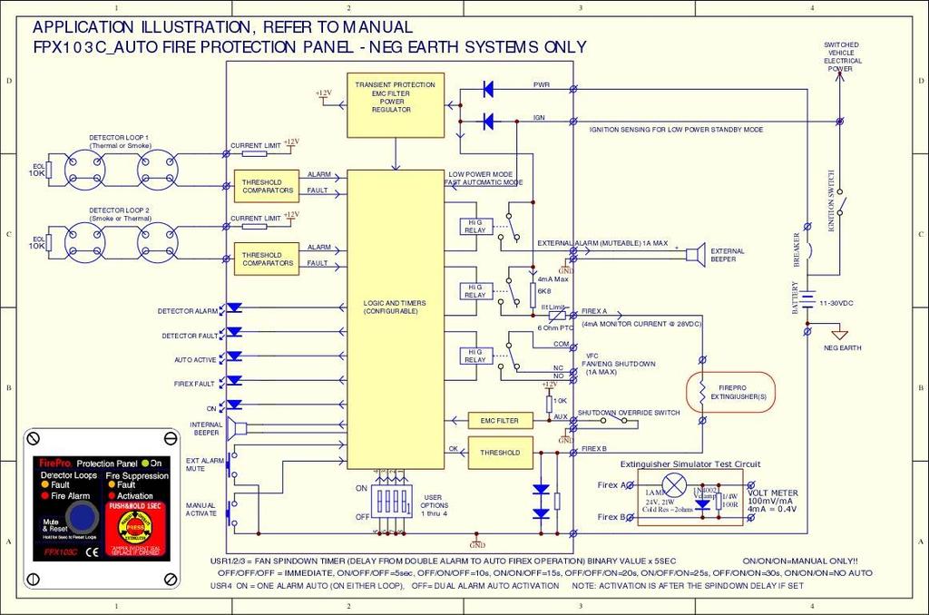
8 Typical Application wiring (Linear Heat Detector sensors)
9 Manufacturer: Logician Ltd 25 The Paddock Maidenhead Berks, SL6 6SD United Kingdom Tel: +44 (0) PRODUCT DISCLAIMERS FirePro Systems makes no representations or warranties of any kind, either express or implied, statutory or otherwise, including but not limited to warranties of merchantability, fitness for a particular purpose, of title, or of non-infringement of third party rights, including the intellectual property rights of others. For Materials or Equipment manufactured by Third Parties and not by FirePro Systems, the Buyer shall only be entitled to the benefit of any such warranty or guarantee as is given by the Third Party manufacturer to FirePro Systems. LIMITATION OF LIABILITY In no event, regardless of cause, shall FirePro Systems be liable for any indirect, special, incidental, punitive or consequential damages of any kind, whether arising under breach of contract, tort (including negligence), strict liability or otherwise, even if advised of the possibility of such damages.
10 FirePro Systems 6 Koumandarias Street, PO Box 54080, CY-3720 Limassol, Cyprus - EU Tel.: Fax: mail@firepro.com
FPX103C Auto DUAL LOOP AUTO/MANUAL FIRE CONTROL PANEL Iss 1.0
 FPX103C Auto DUAL LOOP AUTO/MANUAL FIRE CONTROL PANEL Iss 1.0 SUMMARY: Dual detection loops with full fault monitoring. Automatic extinguisher operation after shutdown. Double knock automatic activation
BTA. (Bulb Thermal Actuator) Data Sheet
 Data Sheet") BTA (Bulb Thermal Actuator) Data Sheet BTA Technical Data Sheet Bulb Thermal Actuators, Series FP-BTA TECHNICAL INFORMATION Bulb according to BSEN12259, UL199, LPCB 291A/02 Thermal Actuator consists of
BTA (Bulb Thermal Actuator) Data Sheet BTA Technical Data Sheet Bulb Thermal Actuators, Series FP-BTA TECHNICAL INFORMATION Bulb according to BSEN12259, UL199, LPCB 291A/02 Thermal Actuator consists of
Application, Installation, Operation & Maintenance Manual
 APPROVED BY:JBJ PRESCIENT III FIRE ALARM & GAS EXTINGUISHING CONTROL PANEL Application, Installation, Operation & Maintenance Manual PAGE 1 of 43 CONTENTS 1. INTRODUCTION... 3 2. GENERAL DESCRIPTION...
Installation, Operating and Maintenance Manual
 STATUS ZONES CONTROLS FIRE FAULT DISABLED FIRE 1 2 3 4 5 6 7 8 TEST FAULT DISABLED 1 5 BUZZER SILENCE RESET 1 2 TEST 2 6 LAMP TEST 3 SUPPLY 3 7 SYSTEM FAULT 4 8 SOUNDERS ACTIVATE/ SILENCE 4 FAULTS INSTRUCTIONS
0$; Installation Instructions. Computerized Control Panel '(6&5,37,21 63(&,),&$7,216 DE5011 1
,&$7,216 DE5011 1") 0$; Computerized Control Panel Installation Instructions '(6&5,37,21 The MAX-5 is a highly reliable, cost effective control panel for residential and commercial applications. Besides being simple to install
0$; Computerized Control Panel Installation Instructions '(6&5,37,21 The MAX-5 is a highly reliable, cost effective control panel for residential and commercial applications. Besides being simple to install
PNC 1000 SERIES 2, 4, 8 Zone Fire Alarm Control Panel
 PNC 1000 SERIES 2, 4, 8 Zone Fire Alarm Control Panel INSTALLATION, OPERATION AND MAINTENANCE MANUAL Version: CN-PM-1000.VER1.1-12/2012 EN54 INFORMATION In accordance with EN 54-2 clause 13.7, the maximum
Control Panel Engineering and Commissioning Instructions
 Twinflex - V3 Fire Detection & Alarm System Control Panel Engineering and Commissioning Instructions (TO BE RETAINED BY THE COMMISSIONING ENGINEER) 26-0338 Issue 9 Fike s policy is one of continual improvement
OPERATION AND INSTALLATION MANUAL
 EX+Plus 2 ZONE, 1AREA EXTINGUISHANT CONTROL PANEL OPERATION AND INSTALLATION MANUAL INTRODUCTION The Premier EX Plus is a 2 zone, single area panel for controlling the release of extinguishing gases in
Intelligent Security & Fire Ltd
 OPERATIONAL NOTES FOR CONCEPT FIRE PANEL. NOTE ON NEW FIRE PANELS, POSITION 1 ON THE SIX WAY INTERNAL OPTION SWITCH IS TURNED ON, DISABLING THE ZONAL SOUNDERS. TO ENABLE ZONAL SOUNDERS TURN OFF. Operation
Installation Instructions
 0$;0$; Computerized Multi-Function Alarm Control Panels Installation Instructions '(6&5,37,21$1'&$3$%,/,7,(6 The MAX-8 and MAX-16 are reliable, cost-effective control panels for residential and commercial
M2500 Engine Controller Installation Manual
 M2500 Engine Controller Installation Manual Revision: 23-04-2012 Page 1 Contents 1 Preface... 4 2 Installation... 5 3 Terminal Connections... 6 4 Inputs... 7 4.1 Power Supply... 7 4.2 Mode/ Control Inputs...
OWNERS MANUAL MODEL 451 (-101 & -201)
") OWNERS MANUAL MODEL 451 (-101 & -201) Guardian Avionics CO Guardian, LLC. 1951 E Airport Drive Tucson, AZ 85756 Phone: 520-889-1177 8:00 am - 5:00 pm MST support@guardianavionics.com 2 Table of Contents
OWNERS MANUAL MODEL 451 (-101 & -201) Guardian Avionics CO Guardian, LLC. 1951 E Airport Drive Tucson, AZ 85756 Phone: 520-889-1177 8:00 am - 5:00 pm MST support@guardianavionics.com 2 Table of Contents
HOKKIM INTEGRATED AMF CONTROL BOARD MANUAL FOR MODELS: HAMF-8 AND HAMF-4
 HOKKIM INTEGRATED AMF CONTROL BOARD MANUAL FOR MODELS: HAMF-8 AND HAMF-4 INTRODUCTION Thank you for purchasing the Hokkim Integrated Automatic Mains Failure Control Board model HAMF- 8 or HAMF-4. We shall
GAS SUPRESSION CONTROL PANEL:
 GAS SUPRESSION CONTROL PANEL: MODEL NAME: COMPANY: DELTA 437/2, Main Road, Mandwali Fazalpur, Delhi-110092 Page 1 ABOUT THE PRODUCT ASES is very proud of to introduce DELTA the completely digital microprocessor
DOLKPL1KB DOLKPS1KB DOLKSF1KB
 DOLKPL1KB DOLKPS1KB DOLKSF1KB USER MANUAL INSTRUCTIONAL VIDEO 1] Connection Terminals 2] Basic Wiring Example 3] Quick Start Guide 4] Programming Guide 5] Specifications 1 Connection Terminals The DOLKPS1KB/DOLKPS1KB/DOLKSF1KB
1200-HCM DIN RAIL MOUNTING FIRE SYSTEM MODULE Fire Detection & Extinguishant Control A R T PATOL LIMITED SUPPLY FAULT SOUNDER
 Application The unit is primarily intended for use where there is a requirement to integrate a limited fire protection function into a larger control equipment scheme, or in specialist applications where
Premier Hazard STC Instructions
 PREMIER HAZARD Ltd Bessingby Industrial Estate Bridlington YO16 4SJ Tel: +44 (0) 113 239 1111 Fax: +44 (0) 113 239 1131 www.premierhazard.co.uk info@premierhazard.co.uk Premier Hazard STC Instructions
EVD-1 Installation, Operation, and Instruction Manual
 EVD-1 Installation, Operation, and Instruction Manual Electronic Vibration Detector System (All specifications subject to revision.) EVD-1 Controller RTA (optional) POTTER ELECTRIC SIGNAL COMPANY, LLC
Sigma. K1000 Series 1, 2, 4 & 6 Zone Fire Control Panels. Operation and Maintenance Manual. Man-1048 Issue 05 October 2009
 Sigma K1000 Series 1, 2, 4 & 6 Zone Fire Control Panels Operation and Maintenance Manual Man-1048 Issue 05 October 2009 CONTENTS Contents... Page Safety & Installation...2 Installation - continued...3
DUAL MONITORED INPUT/OUTPUT UNIT BN-305
 DUAL MONITORED INPUT/OUTPUT UNIT BN-30 Interactive fire detection systems Product Datasheet Features Interactive For interfacing and controlling external units to Autronica s interactive fire detection
OPERATION & INSTALLATION MANUAL FOR ALARM PANEL M2AP01
 OPERATION & INSTALLATION MANUAL FOR ALARM PANEL M2AP01 Table of Contents Safety Instructions 4 Owner/Operator Responsibility 4 Specifications 5 Introduction 6 Installation Instructions 7 Setup 7 Wiring
BEP Marine Gas Detector 600-GDRV
 BEP Marine Gas Detector 600-GDRV Description BEP gas detectors use microprocessor control to ensure correct sensor sensitivity. The 600-GDRV Gas Detector uses the same sensor as the 600-GD and GDL, but
FEC400 Series. Installation Manual
 FEC400 Series Conventional microprocessor controlled fire detection and alarm panels with extinguishing control Installation Manual Version 2.3 / August 2004 Aritech is a GE Interlogix brand. http://www.geindustrial.com/ge-interlogix/emea
Document No
 CO Guardian LLC 1951 E. Airport Dr. Tucson, AZ 85706 CARBON MONOXIDE DETECTOR MODEL 452 INSTALLATION AND OPERATIONAL MANUAL Document No. 01-2510-02 MODEL 452 INSTALLATION AND OPERATIONAL MANUAL Page 1
OWNERS MANUAL. CARBON MONOXIDE DETECTOR MODELS Panel Mount & Remote Detectors (R) Guardian Avionics 1951 E. AIRPORT DRIVE TUCSON, AZ.
 Guardian Avionics 1951 E. AIRPORT DRIVE TUCSON, AZ.") OWNERS MANUAL CARBON MONOXIDE DETECTOR MODELS Panel Mount & Remote Detectors (R) (353-101 and 353-201) 353 FAMILY MODEL OWNERS/INSTALLATION MANUAL Page 1 of 22 LOG OF REVISIONS REV NO. PAGE NO. DATE DESCRIPTION
OWNERS MANUAL CARBON MONOXIDE DETECTOR MODELS Panel Mount & Remote Detectors (R) (353-101 and 353-201) 353 FAMILY MODEL OWNERS/INSTALLATION MANUAL Page 1 of 22 LOG OF REVISIONS REV NO. PAGE NO. DATE DESCRIPTION
HA-263K HA-263D. OWNER'S MANUAL Installation And Operation 8-ZONE ALARM CONTROL PANEL FOR HOME AND OFFICE PROTECTIONS OPEN THE CABINET FOR SERVICE
 D (OPERATION) INITIATE A DYNAMIC BATTERY TEST The system tests the back-up battery once every 24 hours. The owner can initiate a dynamic battery test at any time with the following codes while the system
NEVER ACTIVATE THE STROBE WITH THE PCB OUT OF ITS PROTECTIVE CASE. EXTREME CARE IS ADVISED TO REMOVE THE RISK OF ELECTRIC SHOCK.
 VI64 Version:1.1 Issued 06/12/2007 INTRODUCTION Ventcroft s external sounder/strobes offer an unsurpassed range of models which provide for virtually any installation need. Most models feature a robust
CO Guardian LLC Document: E. AIRPORT DRIVE Date: 11/15/05 OWNERS MANUAL
 OWNERS MANUAL CARBON MONOXIDE DETECTOR MODELS Panel mount and Remote Detectors (R) (353 and 353R) 353 FAMILY MODEL OWNERS/INSTALLATION MANUAL Page 1 of 22 LOG OF REVISIONS REV NO. PAGE NO. DATE DESCRIPTION
SYSTEM MANUAL FT1-SB. Single Zone Fire Alarm System
 SYSTEM MANUAL FT1-SB Single Zone Fire Alarm System DOCUMENT HISTORY Issue Date Description Written By Checked By Draft 0 2/9/2008 Original Document. A. Shenouda C. Orr Issue 1 4/11/2011 Update drawing
BEP Marine Gas Detector FD-2
 BEP Marine Gas Detector FD-2 Description BEP gas detectors use microprocessor control to ensure correct sensor sensitivity. The FD-2 Gas Detector is an economical gas detector with one remote mounted sensor..
Macurco HD-11 Hydrogen Gas Detector User Instructions. Important: Keep these User Instructions for reference
 Macurco HD-11 Hydrogen Gas Detector User Instructions Important: Keep these User Instructions for reference 2 TABLE OF CONTENTS GENERAL SAFETY INFORMATION 4 INTENDED USE 4 LIST OF WARNINGS AND CAUTIONS
DH400. Accessories. NOTE: Set up for this sensor should be performed by an AAADM-certified installer.
 NOTE: Set up for this sensor should be performed by an AAADM-certified installer. Section 1 General Description The is a high mount microprocessor controlled active infrared presence detector for all types
4 & 8-POINT ANNUNCIATORS Instruction Manual
 4 & 8-POINT ANNUNCIATORS Instruction Manual 8 Field Selectable Sequences All Common ISA Sequences 4 or 8-Point (Channel) Monitoring Free Replaceable Message Labels Type 4X, NEMA 4X, IP65 Front Universal
AquiTron. AT-LDM Liquid Detection Module INSTALLATION INSTRUCTIONS
 AquiTron Liquid Detection Module INSTALLATION INSTRUCTIONS Please read these instructions carefully and keep them in a safe place (preferably close to the module) for future reference. These instructions
FR-4000 & FR-8000 Fire Alarm Monitor Installation Manual
 FR-4000 & FR-8000 Fire Alarm Monitor Installation Manual Table of Contents Introduction 1 System Components 2 Wiring Block Diagram 3 Connection Diagram for One Sensor 4 Connection Diagram for Multiple
ACL TC 200 TEMPERATURE CONTROLLER
 TC 200 TEMPERATURE CONTROLLER TC 200 TEMPERATURE CONTROLLER WARNING This manual must be read in its entirety before installation of this controller. Installation must be performed by a qualified technician
Installation Guide for AL800UL-ADA. NAC Power Extender. Rev
 Installation Guide for AL800UL-ADA NAC Power Extender Rev. 090500 Overview: The Altronix AL800UL-ADA is an extremely cost effective 8 amps voltage regulated remote power supply /battery charger. The AL800UL-ADA
USER MANUAL COMBINED FIRE & EXTINGUISHING CONTROL PANEL COMPLIES WITH BS EN PART 1 & EN54 PARTS 2 & 4
 PREMIER EX8 EXTINGUISHING PANEL USER MANUAL COMBINED FIRE & EXTINGUISHING CONTROL PANEL COMPLIES WITH BS EN 12094 PART 1 & EN54 PARTS 2 & 4 USER MANUAL Approved Document No: GLT.MAN-132 INDEX Extinguishing
User s Manual For Model Aero-551 (Rev. Orig.)
") User s Manual For Model Aero-551 (Rev. Orig.) Document: 551-100 REV A LOG OF REVISIONS REV NO. PAGE NO. DATE DESCRIPTION APPROVED Orig. 1 thru 5 12/4/06 Initial Release ASH VIJ A 2 and 3 10/22/06 Deleted
User s Manual For Model Aero-551 (Rev. Orig.) Document: 551-100 REV A LOG OF REVISIONS REV NO. PAGE NO. DATE DESCRIPTION APPROVED Orig. 1 thru 5 12/4/06 Initial Release ASH VIJ A 2 and 3 10/22/06 Deleted
EXTINGUISHING AGENT RELEASE MODULE
 EXTINGUISHING AGENT RELEASE MODULE Operation, Installation & Programming Manual Revision 3.00 Distributors For: 18-20 Brookhollow Ave telephone 02 8850 2888 www.firesense.com.au Baulkham Hills NSW 2153
INSTALLATION MANUAL PC56O. Version 1.OA
 INSTALLATION MANUAL PC56O Version 1.OA TABLE OF CONTENTS INTRODUCTION 3 Features... 3 Specifications... 3 INSTALLATION 4 Mounting the Control Panel... 4 Mounting the Keypad... 4 Wiring... 5 Burglary Zone
PSN-1000 & PSN 1000(E) Installation Manual
 Installation Manual") PSN-1000 & PSN 1000(E) Installation Manual Potter Electric Signal Company, LLC St. Louis, MO Customer Service: (866) 240-1870 Technical Support: (866) 956-1211 Fax: (314) 595-6999 www.pottersignal.com
PSN-1000 & PSN 1000(E) Installation Manual Potter Electric Signal Company, LLC St. Louis, MO Customer Service: (866) 240-1870 Technical Support: (866) 956-1211 Fax: (314) 595-6999 www.pottersignal.com
Control/Communicator Installation Manual
 DAS NETWORX NX-12 Control/Communicator Installation Manual General Description...2 Ordering Information...2 Option Definitions...3 Programming the LED Code Pads...5 Programming the NX-12...9 Types of Programming
highline SVCS-1 INSTALLATION & USER MANUAL SMOKE VENT CONTROL SYSTEM * enclosure design may vary software version: SVCS1r6 SVCS1r7 SVCS1r10
 highline WINDOW CONTROLS INSTALLATION & USER MANUAL SMOKE VENT CONTROL SYSTEM SVCS-1 * enclosure design may vary software version: SVCS1r6 SVCS1r7 SVCS1r10 CERTIFICATE OF COMPLIANCE SVCS-1 We the undersigned
Macurco HD-11 Hydrogen Gas Detector
 Macurco HD-11 Hydrogen Gas Detector User Instructions Important: Keep these User Instructions for reference TABLE OF CONTENTS GENERAL SAFETY INFORMATION 3 Intended Use 3 List of Warnings and Cautions 3
CDMAEZ. CDMA Universal Alarm Communicator INSTALLATION & USER S GUIDE
 INSTALLATION & USER S GUIDE 2015 Uplink Security LLC. All rights reserved. No part of this publication may be reproduced or used in any form without permission in writing from Uplink. This includes electronic
This wiring diagram describes circuit connections for all models of the Series Quaestor-SZU Releasing Fire Control
 File: S8485 Wiring Diagram This wiring diagram describes circuit connections for all models of the Series Quaestor-SZU Releasing Fire Control Panel. The operation of this product is intended for indoor
Installation and user manual for the CF5000, MF5000 and FXP5000 range of fire panels
 CF5000, MF5000 and FXP5000 Installation and user manual for the CF5000, MF5000 and FXP5000 range of fire panels 16 zone panels Contents PANEL INSTALLATION...3 Installation...3 PANEL WIRING... 3 Mains power
Conventional Fire Alarm System 2014 V1.2
 Conventional Fire Alarm System 2014 V1.2 Product Overview Control Panel 2 Conventional Fire Panel GST102A 2 zone Fire panel GST104A 4 zone Fire panel GST108A 8 zone Fire panel GST116A 16 zone Fire Panel
FW-RA-LED Remote Multiplex Annunciator Panels
 FW-RA-LED Remote Multiplex Annunciator Panels WIRING and INSTALLATION INSTRUCTION LNOTICE All information, documentation, and specifications contained in this manual are subject to change without prior
FEC403EN Installation Manual
 FEC403EN Installation Manual P/N 10-4101-501-2FC1-01 ISS 22JAN15 Copyright Trademarks and patents Manufacturer 2015 UTC Fire & Security. All rights reserved. The FEC403EN name and logo are trademarks of
DUAL MONITORED INPUT/OUTPUT UNIT BN-305-2
 DUAL MONITORED INPUT/OUTPUT UNIT BN-305-2 Interactive fire detection systems Product Datasheet Features Interactive For interfacing and controlling external units to Autronica s interactive fire detection
ZIOU/230 - MAINS IO INSTRUCTION MANUAL
 Description ZIOU/230 - MAINS IO INSTRUCTION MANUAL The Mains IO Modules are fully monitored loop powered devices which permit the interfacing of third party equipment with the Fire Alarm Control panel
EC Series Wall Unit Humidifier
 Read and Save These Instructions EC Series Wall Unit Humidifier Controller Operation Manual SEASONAL DRAIN SAFETY CIRCUIT OPEN POWER FILL VALVE OPEN WATER LEVEL FULL COOL DOWN CYCLE DRAIN VALVE OPEN HEATER
636 and 646 Keypads. User s Manual
 636 and 646 Keypads 636 646 User s Manual Table Of Contents Basic Operation... 2 Access Codes... 4 Arming & Disarming... 5 Panic Zones... 11 Key Access Programming... 12 Additional Features... 13 Trouble
EX8. Instruction Manual: COMBINED FIRE & EXTINGUISHING CONTROL PANEL COMPLIES WITH BS EN PART 1 AND EN54 PARTS 2 & 4
 EX8 COMBINED FIRE & EXTINGUISHING CONTROL PANEL COMPLIES WITH BS EN 12094 PART 1 AND EN54 PARTS 2 & 4 Instruction Manual: Approved Document No: GLT.MAN-124 PAGE 2 INDEX INDEX... 3 Introduction... 4 Indications
Installation Manual RINS1211-4
 Installation Manual 2x 2x RINS1211- Contents Page System Overview Technical Specification 5 Overview 6 The Control Panel 6 The Printed Circuit Board The Tamper Spring and Connections 8 Connections 9 Transformer
Model 17A00 Expansion Enclosure
 HOME AUTOMATION, INC. Model 17A00 Expansion Enclosure Installation Manual Document Number 17I00-1 Rev A March, 2002 Home Automation, Inc. Model 17A00 Expansion Enclosure Installation Manual Document Number
MODEL 5100 VOTING LOGIC MODULE
 DESCRIPTION DESCRIPTION The SST Model 5100 Multi-Input Voting Logic Module is used to monitor the status of up to 14 different points in a hazard zone, and report when a selectable number of these points
ESP TECHNOLOGIES LIMITED
 Alarm Technology ESPAN-01 Series Annunciator System Combination type User Manual (Rev. 1) ESP TECHNOLOGIES LIMITED www.esptechno.com Content Page Introduction 2 General Description 2 Overview - Annunciator
PRODUCT INSTRUCTIONS. Fire Door Control Panel (FDCP) Stock Code Description Doc No: PI-115. Ellard Fire Door Control Panel Ellard Slave Repeater Unit
 Stock Code Description Doc No: PI-115. Ellard Fire Door Control Panel Ellard Slave Repeater Unit") PRODUCT INSTRUCTIONS Fire Door Control Panel (FDCP) Floats Rd, Wythenshawe, Manchester. M23 9WB T: 44 (0)161 945 4561 F: 44 (0)161 945 4566 Stock Code Description Doc No: PI115 00133 00134 Ellard Fire
PRODUCT INSTRUCTIONS Fire Door Control Panel (FDCP) Floats Rd, Wythenshawe, Manchester. M23 9WB T: 44 (0)161 945 4561 F: 44 (0)161 945 4566 Stock Code Description Doc No: PI115 00133 00134 Ellard Fire
AL800ULADA. NAC Power Extender. Installation Guide
 AL800ULADA NAC Power Extender Installation Guide Rev. 122000 AL800ULADA - NAC Power Extender Overview: The Altronix AL800ULADA is an extremely cost effective 8 amp voltage regulated remote power supply/battery
Hydrosense. Vimpex Limited. Star Lane. Great Wakering. Essex SS3 0PJ. Tel: +44 (0) Fax +44 (0)
 Fax +44 (0)") Overview of the Water Detection System 2 Components of a System 4 Design & Planning 5 System Installation Notes 7 Control Panel Installation - HSCPI-K3000 8 Control Panel Commissioning HSCPC-K3000 11 Front
Overview of the Water Detection System 2 Components of a System 4 Design & Planning 5 System Installation Notes 7 Control Panel Installation - HSCPI-K3000 8 Control Panel Commissioning HSCPC-K3000 11 Front
Remote NAC Power Supply D7038
 Operation and Installation Guide Remote NAC Power Supply D7038 D7038 REMOTE NAC POWER SUPPLY Page 2 2005 Bosch Security Systems Contents Contents 1.0 Overview...5 1.1 Module Control...5 1.1.1 Option Bus
User s Manual and Warranty Information for Counterweighted Chain Drive ThyssenKrupp Access
 II User s Manual and Warranty Information for Counterweighted Chain Drive ThyssenKrupp Access Part #2139703 Rev. G II Table of Contents Introduction...3 Elevator Overview...4 Description of Features...5-7
30.45 Electric Release PDRP-2001
 The PDRP-2001 Fire Alarm Control Panel (FACP) is a six-zone control panel for single and dual hazard deluge and preaction applications. The FACP is compatible with conventional input devices (2-wire or
FTEN1, FTEN2, & FTEN4 1, 2 & 4 ZONE FIRE DETECTION AND ALARM CONTROL PANELS
 QUICK USER GUIDE FOR, 2 & 4 ZONE PANELS INDICATORS COLOUR INDICATION MON FAULT Yellow On when a fault condition has occurred, or if no other fault Led is on, this indicates 24v auxiliary fuse failure.
CPS-1 USER S MANUAL AIR INLET / CURTAIN CONTROL
 CPS-1 USER S MANUAL AIR INLET / CURTAIN CONTROL temperature / static pressure DIFF Opn Clo ALARM HI F2 DELAY ALARM LO OPEN DELAY CLOSE ADJUST Varifan + CPS-1 CPS-1 Although the manufacturer has made every
MODEL KP-200 VANDAL RESISTANT & WEATHERPROOF FLUSH MOUNT DIGITAL KEYPAD DESIGNED FOR ACCESS CONTROL APPLICATIONS
 MODEL KP-200 VANDAL RESISTANT & WEATHERPROOF FLUSH MOUNT DIGITAL KEYPAD DESIGNED FOR ACCESS CONTROL APPLICATIONS OPERATES ON 12 OR 24 VOLTS AC/DC, AUTO VOLTAGE SENSING FULLY PROGRAMMABLE FROM THE KEYPAD
Use this product according to this instruction manual. Please keep this instruction manual for future reference.
 273 Branchport Avenue Long Branch, NJ 07740 (732) 222-6880 Thank you for using our products. INSTALLATION INSTRUCTIONS REMOTE MICROPHONE (SINGLE CIRCUIT) Use this product according to this instruction
SECURIT 700L PLUS ENGINEERING MANUAL
 SECURIT 700L PLUS ENGINEERING MANUAL C & K Systems Ltd 13/03/97 C031-096-02 NEW ENHANCED FEATURE SET Securit 700L PLUS Engineering instructions INTRODUCTION The Securit 700L is a microprocessor intruder
Heat Pump Defrost Board Replacement Kit
 Bard Manufacturing Company, Inc. Bryan, Ohio 43506 8620-223 Heat Pump Defrost Board Replacement Kit KIT FEATURES This kit is made up of the current defrost control board 8201-129 and a new defrost sensor.
RANGER 8600 DOWNLOADABLE CONTROL COMMUNICATOR INSTALLATION MANUAL
 RANGER 8600 DOWNLOADABLE CONTROL COMMUNICATOR INSTALLATION MANUAL TABLE OF CONTENTS GENERAL DESCRIPTION... 2 STANDARD AND OPTIONAL PARTS LIST... 2 PARTS DIAGRAM... 3 TERMINAL DRAWING AND SPECIAL NOTES...
M2000 Engine Controller
 M2000 Engine Controller Integrated control and protection of diesel and gas engines for all purposes Especially suited for auxiliary generator sets 1 IN OPERATION 1 2 STARTFAIL 2 3 OVERSPEED RPM FAIL 3
USER MANUAL CEF AP28 CONTROL PANEL
 USER MANUAL CEF AP28 CONTROL PANEL AP28 WARNINGS This product has mains voltage present within the housing. Please take the necessary precautions in not allowing any liquid to spill on or into the housing.
KFP-CF Series Operation Manual
 KFP-CF Series Operation Manual P/N 501-415103-2-31 REV 03.10 ISS 13NOV13 Copyright Trademarks and patents Manufacturer Version Certification European Union directives Contact information 2013 UTC Fire
LED Driver Module. These instructions contain procedures to follow in order to avoid personal injury and damage to equipment.
 LED Driver Module Installation Guide 1.0 Notice These instructions are for installing Radionics LED Driver Module in a fire alarm system controlled by Radionics D8024 or D10024 Fire Alarm Control Panels
TABLE OF CONTENTS TABLE OF CONTENTS 1
 TABLE OF CONTENTS TABLE OF CONTENTS 1 FEATURES 2 Keypad Programmable... 2 EEPROM Memory... 2 Static/Lightning Protection... 2 Supervision... 2 Operation... 2 SPECIFICATIONS 2 PC1550 Control Panel... 2
GENERATOR SELF-TEST VERIFIER (GSV300) INSTALLATION INSTRUCTIONS
 INSTALLATION INSTRUCTIONS") GENERATOR SELF-TEST VERIFIER (GSV300) INSTALLATION INSTRUCTIONS Page 1 GSV300 Installation Manual Rev XC INTRODUCTION The GSV300 is an easy to use, multifunction generator monitor that is packed with useful
GENERATOR SELF-TEST VERIFIER (GSV300) INSTALLATION INSTRUCTIONS Page 1 GSV300 Installation Manual Rev XC INTRODUCTION The GSV300 is an easy to use, multifunction generator monitor that is packed with useful
INSTALLATION INSTRUCTIONS
 INSTALLATION INSTRUCTIONS N99V /99 PRM Polarity Reversing Module What is the PRM? The PRM Polarity Reversing Module is used to reverse the polarity of the positive and negative voltages powering smoke
Intelligent Security & Fire Ltd
 full installation, commissioning and operating manuals can be downloaded from www.haes-systems.co.uk combined addressable / conventional fire alarm control panel User Guide Approved Document No. MFBU-04
Flopurge TS. Operation Manual
 Flopurge TS Operation Manual Part Number 079-0204 Spectron Gas Control Systems United Kingdom Unit 4, Herald Court, University of Warwick Science Park, Coventry, CV4 7EZ +44 (0)24 7641 6234 sales@spectron-gcs.com
MODEL 8143 SIGNAL SELECTOR INSTALLATION AND OPERATION MANUAL
 MODEL 8143 SIGNAL SELECTOR INSTALLATION AND OPERATION MANUAL 95 Methodist Hill Drive Rochester, NY 14623 Phone: US +1.585.321.5800 Fax: US +1.585.321.5219 www.spectracomcorp.com Part Number 8143-5000-0050
MODEL EUR -5A AUTOMATIC SNOW/ICE MELTING SYSTEM CONTROL PANEL
 MODEL EUR -5A AUTOMATIC SNOW/ICE MELTING SYSTEM CONTROL PANEL TABLE OF CONTENTS Product Overview... 2 Operation... 3 Installation... 5 Troubleshooting... 9 Ordering Information, Warranty and Service...10
PD154 & PD158 VIGILANTE II ANNUNCIATORS Instruction Manual
 PD154 & PD158 VIGILANTE II ANNUNCIATORS 8 Field Selectable Sequences All Common ISA Sequences 4 or 8-Point (Channel) Monitoring Free Replaceable Message Labels Type 4X, NEMA 4X, IP65 Front Universal Power
THERMOMAX COLTREC RCX 100 MICROPROCESSOR REFRIGERATION CONTROL SYSTEM ENGLISH.
 THERMOMAX COLTREC RCX 100 MICROPROCESSOR REFRIGERATION CONTROL SYSTEM ENGLISH www.thermomax-group.com CONTENTS SECTION 1 - INTRODUCTION... 2 SECTION 2 - INSTALLATION... 3 2.1 - RCX 100 UNIT... 4 2.2 -
Reflective Optical Beam Smoke Detector User Guide
 Reflective Optical Beam Smoke Detector User Guide 1. Installation IMPORTANT NOTE: The infrared beam path MUST be kept clear of obstructions at all times! Failure to comply may result in the system initiating
Public Safety DAS Annunciator Panel
 Public Safety DAS Annunciator Panel 120 VAC Models: 1221-A, 1221-B, 1221-C Revision D 91117 48 VDC Models: 1221-A-48, 1221-B-48, 1221-C-48 24 VDC Models: 1221A-24, 1221-B-24, 1221-C-24 CAUTION: (Read This
1040 Gas Monitor INSTALLATION AND OPERATING INSTRUCTIONS AMC-1040 WITH INTEGRAL ELECTROCHEMICAL SENSOR
 1040 Gas Monitor INSTALLATION AND OPERATING INSTRUCTIONS AMC-1040 WITH INTEGRAL ELECTROCHEMICAL SENSOR IMPORTANT: Please read these installation and operating instructions completely and carefully before
PT9420 (Extended Range)
") (Extended Range) Cable Actuated Sensor Absolute Linear Position to 1700 inches (4300 cm) Stroke Range Options: 0-600 to 0-1700 inches VLS Option to Prevent Free-Release Damage IP68 NEMA 6 Protection Hazardous
(Extended Range) Cable Actuated Sensor Absolute Linear Position to 1700 inches (4300 cm) Stroke Range Options: 0-600 to 0-1700 inches VLS Option to Prevent Free-Release Damage IP68 NEMA 6 Protection Hazardous
VESDAnet Interface Card Product Guide. Document Number: 10672_05 Part Number: 30071
 VESDAnet Interface Card Product Guide Document Number: 10672_05 Part Number: 30071 Xtralis VESDA VESDAnet Interface Card Product Guide Intellectual Property and Copyright This document includes registered
TECHNICAL DATA OBSOLETE
 Deluge Devices 270a 1. PRODUCT NAME VIKING PAR-3 Available since 1991 2. MANUFACTURED FOR: THE VIKING CORPORATION 210 N. Industrial Park Road Hastings, Michigan 49058 U.S.A. Telephone: (269) 945-9501 (877)
Fire Extinguishing Control Panel INSTRUCTION MANUAL. Revision 8/ Instruction Manual Page 1 Revision 8/01.17 of 63
 Fire Extinguishing Control Panel FS5200Е INSTRUCTION MANUAL Revision 8/01.17 Instruction Manual Page 1 1. 2. 3. 4. 4.1. 4.2. 4.2.1. 4.2.2. 4.2.3. 4.2.4. 4.2.5. 4.2.6. 4.2.7. 4.2.8. 4.2.9. 4.2.10. 4.2.11.
AquiTron. AT-WM Water Monitor DATA SHEET
 AquiTron AT-WM Water Monitor DATA SHEET AT-WM Water Monitor The Aquitron AT-WM is a leak monitoring system that has been specifically designed to comply with the requirements of BREEAM (BRE Environmental
CO Guardian LLC Document No E. AIRPORT DRIVE Date: TUCSON, AZ CO Guardian LLC 1951 E. Airport Dr.
 1951 E. AIRPORT DRIVE Date: 8-20-2004 CO Guardian LLC 1951 E. Airport Dr. Tucson, AZ 85706 OWNERS MANUAL CARBON MONOXIDE DETECTOR MODEL 452-201 REMOTE UNIT MODEL 452-201 OWNERS MANUAL Page 1 of 22 INTENTIONALLY
MR-2602 Two Zone Fire Alarm Control Panel
 MR-2602 Two Zone Fire Alarm Control Panel Installation Manual Secutron LT-2015 Rev.3 July 2010 Table of Contents 1 Introduction 1.1 The MR-2602 Fire Alarm Control Unit... 11 1.1.1 General features...
GG-H2S HYDROGEN SULFIDE GAS SENSOR. Installation and Operation Manual
 GG-H2S HYDROGEN SULFIDE GAS SENSOR Installation and Operation Manual 2 GG-H2S Warning Use this product only in the manner described in this manual. If the equipment is used in a manner not specified by
Danfoss gas detection units
 Data sheet Danfoss gas detection units Types GD Premium, Premium+, Premium Duplex, Premium Remote, Premium Flex and Premium Uptime The Premium line gas detection units are used for monitoring and warning
DEIF A/S. Technical Manual. Type EC-2 Engine Control Unit D. Technical Manual
 Technical Manual Type EC-2 Engine Control Unit 4189340232D DEIF A/S Technical Manual DEIF A/S Tel.: (+45) 9614 9614 Frisenborgvej 33, DK-7800 Skive Fax: (+45) 9614 9615 Denmark E-mail: deif@deif.com Contents
OPEARATING GUIDELINES FOR AERO-252 (Pages 1 to 3 contain general information on CO Guardian. Pages 4 to 6 contain information specific to Aero 252)
") OPEARATING GUIDELINES FOR AERO-252 (Pages 1 to 3 contain general information on CO Guardian. Pages 4 to 6 contain information specific to Aero 252) What is Carbon Monoxide? Carbon Monoxide (CO) is a colorless,
OPEARATING GUIDELINES FOR AERO-252 (Pages 1 to 3 contain general information on CO Guardian. Pages 4 to 6 contain information specific to Aero 252) What is Carbon Monoxide? Carbon Monoxide (CO) is a colorless,