Prescriptive and Performance Analysis of Cold Machine Shop FPE 596 Culminating Project
|
|
|
- Loreen McKinney
- 5 years ago
- Views:
Transcription

1 Prescriptive and Performance Analysis of Cold Machine Shop FPE 596 Culminating Project John Kline 8/8/2018
2 Statement of Disclaimer This project report is a result of a class assignment; it has been graded and accepted as fulfillment of the course requirements. Acceptance of this report in fulfillment of the course requirements does not imply technical accuracy or reliability. Any use of the information in this report is done at the risk of the user. These risks may include, but may not be limited to, catastrophic failure of the device or infringement of patent or copyright laws. California Polytechnic State University at San Luis Obispo and its staff cannot be held liable for any misuse of the project. Keywords: Life Safety Code, Performance-Based Design, Fire Dynamics Simulator (FDS), Fire Modeling 1
3 Executive Summary: The purpose of this report is to analyze the fire and life safety aspects of the Cold Machine Shop located on the central coast of California. This report includes both a prescriptive and performance based analysis. The prescriptive analysis will evaluate the building as follows, to ensure compliance with standard codes: Egress analysis and design using NFPA 101, "Life Safety Code" Fire detection, alarms, and communication systems using NFPA 72, "National Fire Alarm and Signaling Code" Water-based fire suppression systems using NFPA 13, " Standard for Installation of Sprinkler Systems" and NFPA 14, " Standard for the Installation of Standpipe and Hose Systems" Structural fire protection using the International Building Code Based on the results of the prescriptive based analysis of this building, only one issue was found with the building. The building met all requirements for egress, water based suppression and structural fire protection. However, one inadequacy was found in the volume of the alarm / notification system in the shop area. While it is believed that the alarms would provide sufficient volume for the actual noise conditions in this area, the inadequacy could easily be remedied by installing an additional 2-3 alarm/notification devices. No other changes or improvements would be recommended at this time. The performance based analysis will evaluate the building using an egress modeling program, a fire sprinkler modeling program, and against separate design fires using FDS modeling. During the performance based analysis, it was determined that a fire in the second floor conference room would not inhibit occupants from having the required time exit while tenability conditions are met for two of the four exits from this floor. The analysis of the shop area pallet fire did show that visibility and temperature would become unacceptable at one exit before everyone exited the building, however the remaining six exits were tenable throughout the simulation. Wood pallets could be disallowed in the building, as they have been in other areas on site, to reduce any risk further. They could be replaced with metal pallets and avoid this hazard altogether. Overall the building was found to be in satisfactory condition and designed appropriately. This report fulfills the completion requirement for the Fire Protection Engineering program at Cal Poly for a Master's of Science. 2
4 Table of Contents Statement of Disclaimer... 1 Executive Summary:... 2 Table of Figures Introduction: Building Overview Egress Analysis: Occupancy Classification Exit Capacities Exit Pathways Fire Resistance and Finishes Signage: Occupant Characteristics Summary: Alarm / Detection Analysis: Detection System Overview: Fire Alarm Control Panels Detection Devices: Detection Device Components: Detection Device Layout: Detection Device Activation: Office Area Shop Area Fan Area Fire Alarm System: Alarm Notification Devices: Alarm Location, Spacing and Placement Mass Notification System (Site PA System): Fire Alarm System Secondary Power Supply: Inspection, Testing and Maintenance Requirements: Field Devices Tested: Signaling Devices: Supervisory Functions: Panel Operations: Panel Operations:
5 4.9. Summary: Water Based Suppression Systems: Water Supply: Riser: Riser Components: Sprinklers: Sprinkler Components: Hose Reels Stations: Hydraulic Calculations: Manual Calculations: AutoSPRINK Calculations: Overall Results: Inspection, Testing and Maintenance Requirements: Inspections: Testing: Maintenance: Summary: Structural Fire Protection: Building Attributes: Use and Occupancy Classifications: Building Stories: Building Area: Building Height: Materials: Fire Resistance Requirements: Required Separation of Occupancies: Fire-Resistance Rating Requirements for Exterior Walls: Prescriptive Analysis Overview: Performance Based Analysis: Overview: Egress - Pathfinder: Results: ASET / RSET - Pyrosim and FDS Design Fires: RSET:
6 Tenability Limits: Results: Conclusion and Recommendations: References: Appendix A: Panel Information Appendix B: Sprinkler / Detector Information Appendix C: Alarm Locations Appendix D: Alarm Information Appendix E: Sprinkler Layouts Appendix F: Overview Layout Appendix G: Hydrant Tests Appendix H: Piping Isometrics Appendix I: Manual Hydraulic Calculations Appendix J: AutoSPRINK Calculations Appendix K: Structural Drawing Markups Appendix L: Pathfinder Simulation Appendix M: Pallet Fire Simulation Appendix N: Office Fire Simulation
7 Table of Figures Figure 1: Geographic Location Figure 2: North Side View Figure 3: First Floor Layout Figure 4: First Floor Maintenance Shop Figure 5: First Floor Electrical Shop Figure 6: First Floor Office Figure 7: Second and Third Floor Layout Figure 8: Second Floor Office Area Figure 9: Second Floor Office Area Figure 10: Second Floor Conference Room Figure 11: Third Floor HVAC Room Figure 12: Third Floor HVAC Room Figure 13: Third Floor HVAC Room Figure 14: First Floor Occupancy Classifications Figure 15: Second and Third Floor Occupancy Classifications Figure 16: First Floor Signage, Common Path, and Exit Separation Figure 17: Second and Third Floor Signage, Common Path, and Exit Separation Figure 18: Annunciator Panel Figure 19: Fire Alarm Control Panels Figure 20: Firewater Riser Figure 21: Firewater Riser Figure 22: Lower Sprinkler System Layout Figure 23: Upper Sprinkler System Layout Figure 24: Office Area DETACT Model Figure 25: Shop Area DETACT Model Figure 26: HVAC Area DETACT Model Figure 27: Alarm Horn and Code Call Bell (Vibratone Type) Figure 28: Code Call Bell (Chime Type) Figure 29: Alarm Horn and Code Call Bell (Vibratone Type) Figure 30: Site PA System Figure 31: Site PA Alarm Figure 32: System Header Isometric Layout Figure 33: Firewater Supply Pump Figure 34: Fire Pump Performance Curve Figure 35: Sprinkler Examples Figure 36: Second Floor Hose Reel Station Figure 37: 1st Floor Hose Reel Layout Figure 38: Water Supply and Demand Figure 39: ASET vs. RSET Figure 40: First Floor Pathfinder Model Figure 41: Second Floor Pathfinder Model Figure 42: Third Floor Pathfinder Model Figure 43: Building Occupant Load vs. Time Figure 44: Pallet Fire HRR vs. Time Figure 45: Pallet Fire Model Figure 46: Pallet Fire Model Perspective View
8 Figure 47: Office Fire HRR vs. Time Figure 48: Office Fire Model Layout Figure 49: Office Fire Model Perspective View Figure 50: Exit Temperatures vs. Time Figure 51: Pallet Fire Visibility vs. Time Figure 52: Pallet Fire Exit Tenability Figure 53: Office Fire Exit Temperatures vs. Time Figure 54: Office Fire Exit Visibility vs. Time Figure 55: Office Fire CO Concentration vs. Time Figure 56: Office Fire Exit Tenability Figure 57: AutoSPRINK Lower System Layout Figure 58: AutoSPRINK Lower System ISO Figure 59: AutoSPRINK Lower System Calculation Results Figure 60: AutoSPRINK Upper System Layout Figure 61: AutoSPRINK Upper System ISO Figure 62: AutoSPRINK Upper System Calculation Results Figure 63: Simulation 0s from NW Corner Figure 64: Simulation 10s from NW Corner Figure 65: Simulation 20s from NW Corner Figure 66: Simulation 30s from NW Corner Figure 67: Simulation 40s from NW Corner Figure 68: Simulation 50s from NW Corner Figure 69: Simulation 60s from NW Corner Figure 70: Simulation 0s from SE Corner Figure 71: Simulation 10s from SE Corner Figure 72: Simulation 20s from SE Corner Figure 73: Simulation 30s from SE Corner Figure 74: Simulation 40s from SE Corner Figure 75: Simulation 50s from SE Corner Figure 76: Simulation 60s from SE Corner Figure 77: Pallet Fire CO Concentration vs. Time Plot Figure 78: Pallet Fire 0s - Top View Figure 79: Pallet Fire 100s - Top View Figure 80: Pallet Fire 126s - Top View Figure 81: Pallet Fire 0s - Side View Figure 82: Pallet Fire 100s - Side View Figure 83: Pallet Fire - Side View Figure 84: Pallet Fire Temperature 0s - Top View Figure 85: Pallet Fire Temperature 100s - Top View Figure 86: Pallet Fire Temperature 126s - Top View Figure 87: Pallet Fire Temperature 0s - View from West Figure 88: Pallet Fire Temperature 100s - View from West Figure 89: Pallet Fire Temperature 126s - View from West Figure 90: Office Fire Stairwell CO ppm vs. Time Figure 91: Office Fire 0s - Top View Figure 92: Office Fire 54s - Top View Figure 93: Office Fire 108s - Top View Figure 94: Office Fire 180s - Top View
9 Figure 95: Office Fire 0s - View from West Figure 96: Office Fire 54s - View from West Figure 97: Office Fire 108s - View from West Figure 98: Office Fire 126s - View from West Figure 99: Office Fire Temperature 0s - Top View Figure 100: Office Fire Temperature 54s - Top View Figure 101: Office Fire Temperature 108s - Top View Figure 102: Office Fire Temperature 126s - Top View Figure 103: Office Fire Temperature 0s - View from West Figure 104: Office Fire Temperature 54s - View from West Figure 105: Office Fire Temperature 108s - View from West Figure 106: Office Fire Temperature 126s - View from West
10 1. Introduction: The purpose of this report is to analyze the fire and life safety aspects of the Cold Machine Shop located on the central coast of California on an industrial site. This report includes both a prescriptive and performance based analysis. The prescriptive analysis will evaluate the building as follows, to ensure compliance with standard codes: Egress analysis and design using NFPA 101, "Life Safety Code" Fire detection, alarms, and communication systems using NFPA 72, "National Fire Alarm and Signaling Code" Water-based fire suppression systems using NFPA 13, " Standard for Installation of Sprinkler Systems" and NFPA 14, " Standard for the Installation of Standpipe and Hose Systems" Structural fire protection using the International Building Code The results of the prescriptive based analysis of this building and any recommendations will then be presented. The performance based analysis will evaluate the building using an egress modeling program, a fire sprinkler modeling program, and against separate design fires using FDS modeling. The results of the performance based analysis of this building and any recommendations will then be presented. This report fulfills the completion requirement for the Fire Protection Engineering program at Cal Poly for a Master's of Science. 9

11 2. Building Overview The Cold Machine Shop is located on the central coast of California on an industrial site. The building is approximately 133 x 203 giving a covered area of 27,000 ft 2. Figure 1 below shows an overview of the building from above. Figure 2 shows the view of the building looking south, showing the equipment rolling and sliding doors. Figure 1: Geographic Location 10

12 Figure 2: North Side View The building is comprised of shop work areas, storage areas and office areas. Shop areas are used for site employees to test, modify, and repair site materials and equipment to maintain the site. Office areas are the shop workers primary location when they are not in the shop or field working. These areas provide them somewhere to perform paperwork, computer based training, etc. Storage areas are used for staging tooling and materials to support work in the shop areas. The skeleton of the building is constructed of mostly steel beams, concrete walls, and sheet metal siding/roofing. The interior office areas are comprised of steel studs and drywall with minimal carpet. See Figures 3 and 7 below for floor layouts. See Figures 4, 5, 6, 8, 9, 10, 11, 12 and 13 for pictures. Picture locations are denoted by blue arrows and labeled on the layouts. 11

13 Figure 3: First Floor Layout Figure 4: First Floor Maintenance Shop 12


14 Figure 5: First Floor Electrical Shop Figure 6: First Floor Office 13

15 Figure 7: Second and Third Floor Layout Figure 8: Second Floor Office Area 14


16 Figure 9: Second Floor Office Area Figure 10: Second Floor Conference Room 15


17 Figure 11: Third Floor HVAC Room Figure 12: Third Floor HVAC Room 16

18 Figure 13: Third Floor HVAC Room With the basic layout and configuration laid out, the first aspect of the prescriptive based performance that will be analyzed egress requirements. This will take a look at occupant classification and loading, exit capacities, exit configurations and more. 17

19 3. Egress Analysis: 3.1. Occupancy Classification Occupancy classification were analyzed and determined as shown in Figures 14 and 15 below (LSC Chapter 6 and Table ). The first floor is primarily Industrial space with areas of Storage and Business as well. The second floor is almost entirely Business, with two small areas of storage. The third floor is strictly a Mechanical / HVAC room. Figure 14: First Floor Occupancy Classifications 18
.")
20 Figure 15: Second and Third Floor Occupancy Classifications 3.2. Occupancy Loads Table 1 shows the determination of areas, occupancy classification, occupancy load factor, and calculated occupant load (LSC Chapter 6, Table and Sections /2). The total building Occupant Load is 281 people (Floor 1 = 196 people + Floor 2 = 85 people + Floor 3 = 0 people). 19
21 Table 1: Occupant Loads by Room Floor Room # Area Category Occupant Load Factor Occupant Load Weld Shop Industrial Use: General and high hazard industrial Weld Shop Expansion Industrial Use: General and high hazard industrial Receiving Area Storage Use: In other than storage and mercantile occupancies Rigging Loft Storage Use: In other than storage and mercantile occupancies Stairway #4 N/A Restroom N/A Janitors Closet Storage Use: In other than storage and mercantile occupancies Restroom N/A Storage Use: Mechanical Tool Room In other than storage and mercantile occupancies Tool Test Room Industrial Use: General and high hazard industrial Stairway #1 N/A Restroom N/A Restroom N/A Foreman's Office Business Use Foreman's Office Business Use Lapping Room Industrial Use: General and high hazard industrial Foreman's Office Business Use Clean Room Industrial Use: General and high hazard industrial Foreman's Office Business Use Clerk's Office Business Use Foreman's Office Business Use Stairway #2 N/A Clerk's Office Business Use Foreman's Office Business Use Clerk's Office Business Use Foreman's Office Business Use Electrical Shop Industrial Use: General and high hazard industrial Electrical Tool Room Storage Use: In other than storage and mercantile occupancies A 175 Hallway N/A B 252 Issue Room Business Use Motor Overhaul Shop Industrial Use: General and high hazard industrial Machine Shop Industrial Use: General and high hazard industrial Communication Closet N/A Office Business Use Office Business Use Valve Clean Room Industrial Use: General and high hazard industrial Valve Clean Room - Back Room Industrial Use: General and high hazard industrial Floor Total Receiving Area Storage Use: In other than storage and mercantile occupancies Office Area Business Use A 56 Electrical Closet N/A B 7 Communication Closet N/A Stairway #6 N/A Engineers Office Area Business Use Conference Room #2 Business Use Electrical Shop Storage Business Use Storage Area (Offices) Business Use Floor Total 450 Rigging Loft Storage Use: In other than storage and mercantile occupancies Mechanical Room N/A Floor Total Building Total
22 3.3. Exit Capacities The calculated exit capacities for each floor is shown in Table 2 below. For stairways with no doors, the stairway capacity was used for the door capacity of the stairwells. All three floors have adequate exit capacity. See below for calculations (LSC Section and ). Based on the Occupant Loads and requirements of the LSC each floor has the acceptable number of exits. Floors 1 and 2 have over the requirement. Based on the LSC, Floor 3 is not required to have two exits as it is a story used exclusively for mechanical equipment (LSC Section ). Floors 1 and 2 do have the proper separation of exits as shown in Figures 16 and 17. Floor 1 has multiple examples of separation over 80ft. Floor 2 has 3 instances of exit separation greater than 58ft. These values are based on the building being sprinklered and abiding by the 1/3 rule (LSC Section ). Table 2 below shows the measured values. This building does not employ any horizontal exits to move people to safe areas. Table 2: Exit Capacities Occupant Exit Capacity Required Available Diagonal 1/3 Diagonal Load Stairways Doors Exits Exits Distance Distance Floor Floor Floor Total 281 Floor 2 Stairway Capacity = 40 inches.3 inches person + 38 inches.3 inches person Floor 3 Stairway Capacity = 42 inches.3 inches person = 705 people 36 inches.3 inches person + ( ( = 120 people 48 inches 44inches.218 )) + 42 inches.3 inches person + Floor 1 Door Capacity = 36 inches 36 inches 36 inches =. 2 inches + person. 2 inches + person. 2 inches person 36 inches 36 inches 36 inches +. 2 inches + person. 2 inches + person. 2 inches person 36 inches 36 inches 36 inches +. 2 inches + person. 2 inches + person. 2 inches = 1620 people person 21

23 Floor 2 Door Capacity = 36 inches 48 inches 44inches 42 inches =. 2 inches + ( ( )) + person inches person 40 inches 38 inches +. 3 inches + person. 3 inches = 745 people person 36 inches Floor 3 Door Capacity = = 180 people. 2 inches person Figure 16: First Floor Signage, Common Path, and Exit Separation 22

24 Figure 17: Second and Third Floor Signage, Common Path, and Exit Separation 3.4. Exit Pathways Given the fact that the building is sprinklered, the travel distance is 300ft for Business classification, 250ft for Industrial - General Classification, and 400ft for Storage - Ordinary Hazard Classification (LSC Table A.7.6). Given the diagonal distances for each floor are less than those values, there is no issue with travel distance. As measured, none of the travel distances to an exit on any floor even exceed 150ft, and are not even close to 250ft (The most restrictive of the three classifications), thus meeting the LSC requirements. The Common Path Limits for Business, Industrial, and Storage Classifications are all 100ft (LSC Table A.7.6). The required Common Path does not seem to be an issue other than on the Floor 1. The longest Common Path measured was 48ft which is shown on Figure 16. Floor 2 has a maximum common Path of 40ft. With only one exit on Floor 3, the common path is 80ft for this floor. Floor 2 and 3 examples are shown on Figure 17. The Dead End Limits for Business, Industrial, and Storage Classifications are 50ft, 50ft, and 100ft, respectively (LSC Table A.7.6).During evaluation of the building, no Dead Ends were identified Fire Resistance and Finishes The required fire resistance rating for the stairway enclosures would be 2hr fire rating for the walls/partitions and 1-1/2hr for the doors (LSC Table ). The required fire resistance rating for the exit corridors would be 1hr fire rating for the walls/partitions and 1/3hr for the doors (LSC Table ). 23
25 The Interior Finish Classification Limitations for the building could be A or B. To save costs and effort Class B would be the prudent class to use. (LSC Table A ) Based on the assumption that Class B is the prescribed or used class, the requirements for interior wall and ceiling finish materials, except as shown in table A.10.2, would be tested per ASTM E 84 or ANSI/UL 723, accepted per Class B, in accordance with (2), applied as required by section (LSC Table A.10.2) 3.6. Signage: Exit signage placement should be placed in accordance with the LSC (LSC Section 7.10). Specific considerations include placing signage every 100ft minimum (LSC Section ), marking dead ends or non-exit routes that could be misconstrued for exit routes (LSC ), directing people when the direction to the next exit may be unclear (LSC ) and marking exits/stairwells. (LSC ) See Figures 16 and 17 mark-ups for specific locations Occupant Characteristics A number of factors of the occupancy of this building make it conducive to short evacuation times. Most people in this building will be familiar with the layout and configuration of the building. Employees work in the building daily and will be quite familiar with the layout. Additionally, the building will generally not be populated at night and will not have people sleeping there so all people present at the start of a fire will be awake and alert. Employees would have a good sensibility, reactivity, mobility, and susceptibility. (LSC Section ) This can be derived from their age and professionalism. They would also be alert, focused, capable, and familiar with the building leading to short times. However, some employees may be unresponsive due to lack of concern for the alarm, uncommitted due to lack of concern for the alarm, and not have a designated role and poor affiliation due to age and desire not to stand out. Table 3 below shows a simple calculation of egress time using the SFPE formula. Using that formula, the egress time for the building was found to be 48 seconds. Later in this report a simulation program will be used that uses the actual building configuration to calculate egress time. SFPE: Maximum specific flow = 1.3 P/s/m (doorway) t(min) = Occupant Load 1.3 w e Table 3: Egress Times Occupant Total Effective Door Total Effective Door Widths (w e ) Load Widths (w e ) (ft) (m) t(s) t(min) Floor Floor Floor Total 281 Total
26 Assumptions related to these calculations would be as follows: All people start evacuation at same instant; All people able bodied and have no interruptions in evacuation; All floors are exactly the same; both stairwells are available; no issues or limiting factors on the first floor; assumed ALL floor space in calculation of occupant load with no subtractions. Some limitations to the above calculations for exit time would include the assumptions above tending to optimize egress times and therefore will tend to underestimate actual egress times, and the Occupant Loads will vary widely and often will be less than prescribed as many employees spend their day in the field performing work, thus their office/work space will sit open during certain times of the day. Additionally, this method fails to account for any restrictions or issues within each floor. It assumes that the doors/stairwells are the limiting factor in every case Summary: After analyzing the building based upon NFPA 101: Life Safety Code, the Cold Machine Shop meets all aspects of the code. It was found to have proper separation of exits, exit capacity, exit pathway characteristics and signage. No issues were found during the egress analysis. The next section of the analysis will look at system that notifies the occupants that they should exit a building during a fire, the alarm and detection system. This analysis will look at the devices and their controllers, system layout, system operation, system testing/maintenance and a warning additional system that is installed in the building. 25

27 4. Alarm / Detection Analysis: 4.1. Detection System Overview: The building is completely sprinklered with an upper and lower system sprinkler system. Upright and pendent sprinklers of varying size are utilized throughout. The building is also covered by standpipe/hose system. These are used as the detection devices for actuation of the fire alarm. The building fire annunciator panel and fire alarm control panels are located in the southwest corner of the building on the opposite side of the wall from each other. These panels communicate with the panels / alarm systems of the other buildings on site and would actuate an alarm in those buildings as well if the fire system were to actuate in the Cold Machine Shop. Likewise the alarms would actuate in the Cold Machine Shop if a system were actuated in another building on site Fire Alarm Control Panels The annunciator panel (DC-0-18-I-PNL-DGP05) is a Johnson Controls model IFC Intelligent Addressable Fire Alarm System. Figure 18 below shows the location of the panel in the southwest corner of the building. See Appendix A for detailed panel information. Figure 18: Annunciator Panel 26

28 The Fire Alarm Control Panels (DC-0-97-E-PNL-EACC6/6A) are a Federal Signal Corp. model 300SSC Supervised SelecTone Command - Series B Figure 19 below shows the location of the panel in the southwest corner of the building. See Appendix A for detailed panel information. Figure 19: Fire Alarm Control Panels 27

29 4.2. Detection Devices: The primary detection device used in this building is the sprinklers. As stated before the building is completely sprinklered. The hose reels are also used as a detection device. If actuated they trip a flow switch that would actuate an alarm. Figures 20 and 21 show the firewater main coming into the building and show the main splitting into the three system risers. The blue arrows point to the flow switches that act as the actuation element for the panels when the sprinklers or hose reel system actuates. There are no smoke detectors installed throughout the building. However, there are ones installed in the third floor mechanical room where the supply and exhaust fans are housed. Controls for the fans are at this location and at the Motor Control Center of the second-floor electric shop. Photoelectric smoke detectors are used to shut down the Supply and Return Air Systems. Detectors are resettable at the temperature control panels that are on the exterior of the main duct. See Appendix B for sprinkler / detector information Detection Device Components: 1/2" Reliable Upright rated at 175 F / 155 F - Standard Response 1/2" Reliable Pendent rated at 175 F / 155 F - Standard Response 17/32" Reliable Upright rated at 175 F / 155 F - Standard Response Smoke detectors - Could not locate any information on the smoke detectors used in the HVAC ducting in the Mechanical room Riser Components: 6" Clow Gate Valve 4" Reliable Check/ Alarm Valve (2) 4" Kennedy Gate Valve 2.5'' Kennedy Gate Valve V52-D Potter Electric Flow Switches OSYS-4 Potter Electric Tamper Switches HLPS Potter Electric Alarm Pressure Switch Schedule 40 steel pipe Figure 20: Firewater Riser 28

30 Figure 21: Firewater Riser 4.3. Detection Device Layout: As the sprinklers are used as the main detection devices, Section of NFPA 72 (2016) defines the spacing requirements. Section states that detectors shall not exceed their listed spacing and shall be within half that distance from walls and no point shall be more than 0.7 times that spacing from a detector. This is similar to smoke detectors without the 30' nominal spacing requirement. Figure 22 shows the installed layout of the lower sprinkler system and Figure 23 shows the layout of the upper sprinkler system. The yellow represents the lower sprinkler system and the orange represents the upper sprinkler system. Blue and green represent portions of the hose reel systems, while purple represents the Fire Department Connection. The cold machine shop sprinklers were designed to an Ordinary Hazard, Group II with a density of 0.19gpm/ft 2 and an application area of 1500ft 2. Figure 22 shows the layout of the lower sprinkler system and Figure 23 shows the layout of the upper system. Based on FIGURE Density/Area Curves of NFPA 13 (2013) these are not the current appropriate values for design for this building, however they were acceptable at time of design. Looking at the sprinkler layout and based on analysis performed in FPE 523 it would appear the sprinklers meet any and all spacing requirements of NFPA 72 and NFPA


31 Figure 22: Lower Sprinkler System Layout Figure 23: Upper Sprinkler System Layout 30
32 4.4. Detection Device Activation: The activation times and characteristics were calculated for three areas using the DETACT model. The three areas chosen to look at were the office areas, the shop area, and the third floor mechanical room. These three areas were shown for their distinct characteristics. The shop area has a 30ft ceiling, while the office area and mechanical room have 8.5ft ceilings Office Area In the office area a medium growth rate was chosen as it falls in line with industry experiments (Design Fires for Means of Egress in Office Buildings based on Full-scale Fire Experiments). No cap was set on HRR. Sprinkler Assumptions: Nominal Spacing = 13ft x 10ft = 3.96m x 3.05m Radial distance = 8.2ft / 2.5m (0.7 x Nominal Spacing) Ceiling Height = 8.5ft / 2.6m Actuation Temperature = 155 F / 68 C (Appendix C) RTI = 80 m-s1/2 - Ordinary Response (NFPA Section 3.6.1) INPUT PARAMETERS Table 4: Office Area DETACT Model Inputs CALC. PARAMETERS Ceiling height (H) 2.6 m R/H Radial distance (R) 2.5 m dt(cj)/dt(pl) Ambient temperature (To) 20 C u(cj)/u(pl) Actuation temperature (Td) 68 C Rep. t2 coeff. k Response time index (RTI) 80 (m-s)1/2 Slow Fire growth power (n) 2 - Medium Fire growth coefficient (k) kw/s^n Fast Time step (dt) 2 s Ultrafast
33 TEMP (C) HRR (kw) Cold Machine Shop FPE TIME (s) Gas temp Det temp Det Temp Label HRR HRR Label Figure 24: Office Area DETACT Model Table 5: Office Area DETACT Activation Time Calculation time (s) HRR Gas temp Gas velocity Det temp dt/dt Shop Area The shop area does not have a lot of fuel to speak of. Most of the area is made of concrete and masonry block. Most materials within the area are metal or metal machining equipment, however it could have pallets inside, so a medium fire growth rate was chosen. A peak HRR was of around 9000kW was used based on a pallet fire. Sprinkler Assumptions: Nominal Spacing = 13ft x 10ft = 3.96m x 3.05m Radial distance = 8.2ft / 2.5m (0.7 x Nominal Spacing) Ceiling Height = 34ft / 10.36m Actuation Temperature = 175 F / 79 C (Appendix C) RTI = 80+ m-s1/2 - Ordinary Response (NFPA Section 3.6.1) 32
34 TEMP (C) HRR (kw) Cold Machine Shop FPE 596 Table 6: Shop Area DETACT Model Inputs INPUT PARAMETERS CALC. PARAMETERS Ceiling height (H) m R/H Radial distance (R) 2.5 m dt(cj)/dt(pl) Ambient temperature (To) 20 C u(cj)/u(pl) Actuation temperature (Td) 79 C Rep. t2 coeff. k Response time index (RTI) 80 (m-s)1/2 Slow Fire growth power (n) 2 - Medium Fire growth coefficient (k) kw/s^n Fast Time step (dt) 2 s Ultrafast TIME (s) Gas temp Det temp Det Label HRR HRR Label Figure 25: Shop Area DETACT Model Table 7: Shop Area DETACT Model at Activation Time Calculation time (s) HRR Gas temp Gas velocity Det temp dt/dt Fan Area The fan area does not have any fuel to speak of in the area. A slow fire growth coefficient was chosen because of this. It is assumed that the fire keeps growing with no cap on HRR. 33
35 TEMP (C) HRR (kw) Cold Machine Shop FPE 596 Sprinkler Assumptions: Nominal Spacing = 13ft x 10ft = 3.96m x 3.05m Radial distance = 8.2ft / 2.5m (0.7 x Nominal Spacing) Ceiling Height = 8.5ft / 2.6m (Fan Area) Actuation Temperature = 68 F + 13 F = 71 F / 20 C C = 27.2 C (NFPA Table B ) RTI = 2 m-s1/2 (Detector inaccurate based on heat so low RTI) Table 8: HVAC Area DETACT Model Inputs INPUT PARAMETERS CALC. PARAMETERS Ceiling height (H) 3.6 m R/H Radial distance (R) 3.2 m dt(cj)/dt(pl) Ambient temperature (To) 20 C u(cj)/u(pl) Actuation temperature (Td) 27.2 C Rep. t2 coeff. k Response time index (RTI) 2 (m-s)1/2 Slow Fire growth power (n) 2 - Medium Fire growth coefficient (k) kw/s^n Fast Time step (dt) 2 s Ultrafast TIME (s) Gas temp Det temp Det Label HRR HRR Label Figure 26: HVAC Area DETACT Model Table 9: HVAC Area DETACT Activation Time Calculation time (s) HRR Gas temp Gas velocity Det temp dt/dt
36 4.5. Fire Alarm System: The system installed in the Cold Machine Shop is at its core a Protected Premises System. The main purpose is to active the audible alarms to notify the occupants that they must evacuate. The system includes alarm, supervisory and trouble signals. The alarm signal encompasses the audible alarms activated by the activation of the flow switches for the sprinklers / hose reels as well as the duct smoke detectors. The supervisory signals are the actions signals to the onsite Fire Department to take action based on a fire event in the Cold Machine Shop. These come from the tamper switches on the riser manifold. The trouble signal could include a signal from the tamper switches or loss of primary or secondary power. The Cold Machine Shop's system also includes a Proprietary System component. All buildings onsite are part of an interconnected system that is monitored by the main control room for the site. The system also includes the automated actions of shutting down the supply fans if the smoke detectors on the ducts detect smoke. The requirements for the system setup and signals are located in NFPA 72, Ch. 23 Protected Premises Fire Alarm Systems, Ch. 26 Supervising Station Alarm Systems and Annex C System Performance and Design Guide Alarm Notification Devices: Selectone Site Emergency/Fire Alarm Horn (Appendix D for additional Data) Federal Selectone Audible Signaling Device Model 50GC, with 300CKS connector kit for indoor use, ceiling flush mounting, 24VDC, color beige with FG grill and FBL box. For use with 300SSC Selectone Command Module Decibel Output = 88 at 10 Feet / 98 at 1 Meter Code Call Bell - Chime type Federal single-stroke chime, model 101, rated 120VAC, 60Hz Decibel Output = 98 at 10 Feet / 108 at 1 Meter Code Call Bell - Vibratone Type (Appendix D for additional Data) Federal Vibratone bell, single stroke mechanism model 700, 120VAC, 60Hz. Four inch gong assembly model A4 and knockout box model NB, for indoor use, color grey. Decibel Output = 98 at 10 Feet / 108 at 1 Meter See Figure 27, 28, and 29 for examples of each notification device installed in the building. See Appendix C for location. 35


37 Figure 27: Alarm Horn and Code Call Bell (Vibratone Type) Figure 28: Code Call Bell (Chime Type) 36

38 Figure 29: Alarm Horn and Code Call Bell (Vibratone Type) Alarm Location, Spacing and Placement NFPA 72, Section 18 prescribes the requirements for audible alarms. The maximum dba of the ambient and alarm shall be no greater than 110 dba. Per the alarm shall be at least 15 db above ambient or 5dB above maximum. Per , if ceiling heights allow, and unless otherwise permitted by through , wall-mounted appliances shall have their tops above the finished floors at heights of not less than 90 in. (2.29 m) and below the finished ceilings at distances of not less than 6 in. (150 mm) Ceiling-mounted or recessed. Per , mounting heights other than required by and shall be permitted, provided that the sound pressure level requirements of for public mode are met. Based on an alarm db of 88dB at 10ft, the alarm would produce 82dB at 20ft, 76dB at 40ft, 70dB at 80ft, and 64dB at 160ft. The Cold Machine Shop is generally used as office / class room setting (Similar to an Education occupancy = 45dBA (NFPA 72, Table A )) with some louder industrial type work in the shop area (Similar to an industrial occupancy = 80dBA (NFPA 72, Table A )), however the majority of the time the building is fairly quiet. No place in the building is more than 160ft from an alarm, thus no point would receive anything less than 64dB from the alarm. This would meet the office / classroom requirement of 60dB (45dBA + 15dB). The industrial areas of the shop are no more than 60ft from an alarm. Assuming the industrial ambient to be a maximum in the shop, the requirement would be 80dBA + 5dBA = 85dB. It does not appear that the requirement would be met as the alarm db at a 37

39 conservative distance of 80ft would be 70dB. While this does not meet the requirement laid out in NFPA 72, I believe that the 80dBA to be a gross overestimation based on my experience in the shop. I have never been in the shop where I have had to raise my voice in the slightest to communicate with someone standing next to me. Overall the alarms are installed properly throughout the office areas, except in the shop area, where it appears the area is one or two alarms short of complying with the code. Area Table 10: Alarm Performance: Required vs. Provided Ambient dba Required db Distance from Alarm (ft) Alarm Volume (db) Office Industrial See Appendix C for alarm locations Mass Notification System (Site PA System): The site is equipped with a PA system to make announcements. While not directly controlled or connected to the fire alarm / notification system, this would be used to communicate information to employees' onsite in the event of a fire or any other emergency. The PA system is located in every area of every building onsite and designed to be heard by everyone no matter the location or noise level of that location. Announcements are made from the main control room of the site which in almost any circumstance would be isolated from any fire onsite and would definitely be isolated from a fire in the Cold Machine Shop. See Figures 30 and 31 below for pictures of this additional system. Figure 30: Site PA System 38
 the secondary power for the fire alarm system would be required to provide stand by power for 24 hours and alarming power for 15 minutes.")
40 Figure 31: Site PA Alarm 4.7. Fire Alarm System Secondary Power Supply: Based on Section "Secondary Power Supply" of NFPA 72 (2016) the secondary power for the fire alarm system would be required to provide stand by power for 24 hours and alarming power for 15 minutes. Based on a calculation of the load requirements for this system (See Appendix F), to provide the requirements of NFPA 72, the annunciator panel would need a battery of 19.1 Ah. The annunciator panel is equipped with a 26 Ah capacity so it easily meets the requirements. The FACP would require a battery of 6.9Ah and contains an 8Ah battery. This would also meet the requirements of NFPA 72. The calculations for these values are shown in Table 11 for the Annunciator Panel and Table 12 for the FACP. 39
41 Table 11: Annunciator Panel Battery Load Calculation Johnson Controls - IFC-3030 Intelligent Addressable Fire Alarm System Total Current Current (Amps) (Amps) Device Quantity Standby Alarm Standby Alarm CPU-3030D - IFC-3030 Primary Display NCM-W - Network Communications Module, Wire LCM Loop Control Module LEM Loop Expander Module RPT-W - Repeater Board, Wire Connection XP10-M - Ten-input monitor module XP6-R - Six-Supervised Control Module AMPS-24 - Power Supply Total (Amps) Duration (hr) Required Amp-hr (Ah) Margin of 20% (Ah) Total Batter Demand (Ah) Batter Capacity (Ah) 26 Table 12: FACP Battery Load Calculation SelecTone Supervised Command Unit - Model 300SSC Current (Amps) Total Current (Amps) Device Quantity Standby Alarm Standby Alarm SelecTone Audible Signaling Device - Model 50GC Vibratone Bells k End of Line Resistor Inspection, Testing and Maintenance Requirements: 40 Total (Amps) Duration (hr) Required Amp-hr (Ah) Margin of 20% (Ah) Total Batter Demand (Ah) Batter Capacity (Ah) 8Ah NFPA 72, Chapter 14 prescribes the inspection, testing and maintenance requirements for a fire alarm system. Table specifically calls out "Visual Inspections" and calls out "Testing". Regarding the Cold Machine Shop, some inspections are performed by the Fire Department Staff onsite. However the majority of inspection and testing is contracted out to
42 vendor Cosco. Maintenance is performed on the system by both the onsite maintenance personnel and Vendor Cosco. The following is a list of inspections/testing performed by Cosco as part of an annual inspection: Field Devices Tested: Duct Detectors - Photoelectric (4): Found functional and satisfactory Water Flow Switches - Paddle (2): Found functional and satisfactory Tamper Switches (3) Signaling Devices: 1 Bell: Found functional Supervisory Functions: Main Power: Found satisfactory Backup Power: Found satisfactory Trouble Silence Switch: Found satisfactory Trouble Audible: Found satisfactory Trouble Visual: Found satisfactory Ground Fault: Found satisfactory Disconnect Switches: Found satisfactory Panel Operations: Initiating Circuits: Found satisfactory Signal Circuits: Found satisfactory Alarm Silence Switch: Found satisfactory Alarm Reset Switch: Found satisfactory Lamp Test Switch: Found satisfactory All Lamps/LED's: Found satisfactory Panel Operations: Central Station: Found satisfactory 4.9. Summary: Upon analysis of the building based on NFPA 72, 72A, 72D and 13, the Cold Machine Shop was found to meet most aspects of the code, with the exception of the required notification volume in the shop area. The detection system, devices, layout and testing are all appropriate for the building. The notification system devices themselves are appropriate, however, the layout and number of devices could be improved to ensure the volume requirements meet the code. The next section of the analysis will look at the system that is used for detection, the water based suppression system. This analysis will look at the water supply, riser, sprinklers, hose reel systems, system capabilities and demand, as well as, system testing and maintenance. 41
43 5. Water Based Suppression Systems: The building is completely sprinklered with an upper and lower system sprinkler system. Upright and pendent sprinklers of varying size are utilized throughout. The building is also covered by standpipe/hose system. An isometric view of the system headers/primary piping is shown below in Figure 32. The yellow represents the lower sprinkler system and the orange represents the upper sprinkler system. Blue and green represent portions of the hose reel systems, while purple represents the Fire Department Connection. See Appendix E for detailed sprinkler layouts. Figure 32: System Header Isometric Layout 5.1. Water Supply: Water is supplied to the building from two firewater pumps and a 470,000 gallon tank. Fire water pumps are single stage, horizontal, split case, centrifugal pumps. Figure 33 shows an example of one of the pumps. The pumps provide the following tested pressures and flow: Static Pressure = 165 psi Flowing Pressure = 132 psi (See Appendix G for test data) Flow = 3002 gpm (See Appendix G for test data) 42

44 Figure 33: Firewater Supply Pump Figure 34 below shows the design and minimum performance curves for the fire pumps. See Appendix F for overview layout of supply system. Figure 34: Fire Pump Performance Curve 43
45 Water is fed to the building via a 12 PVC main. This reduces to an 8 line that enters the building. This feed one riser that feeds both sprinkler systems and the standpipe system. There is one Fire Department Connection at the southeast corner of the building Riser: One riser manifold feeds the fire systems for the building. The riser consists of three risers; one for each portion of the system. The riser is located just inside the building one the west side just south of the midpoint. See Appendix H for piping isometrics Riser Components: 6 Clow Gate Valve 4 Reliable Check/Alarm Valve (2) 4 Kennedy Gate Valve 2.5 Kennedy Gate Valve V52-D Potter Electric Flow Switches OSYS-4 Potter Electric Tamper Switches HLPS Potter Electric Alarm Pressure Switch Schedule 40 steel pipe 5.3. Sprinklers: The cold machine shop sprinklers were designed to an Ordinary Hazard, Group II with a density of 0.19gpm/ft 2 and an application area of 1500ft 2. Figure 22 shows the layout of the lower sprinkler system and Figure 23 shows the layout of the upper system. Based on FIGURE Density/Area Curves of NFPA 13 (2013) these are not the current appropriate values for design for this building, however they were acceptable at time of design. Looking at the sprinkler layout and based on analysis performed in FPE 523 it would appear the sprinklers meet any and all spacing requirements of NFPA 13. See Appendix B for further sprinkler information Sprinkler Components: o o o ½ Reliable Upright rated at 175 F / 155 F - Standard Response ½ Reliable Pendent rated at 175 F / 155 F - Standard Response 17/32 Reliable Upright rated at 175 F / 155 F - Standard Response 44


46 Figure 35: Sprinkler Examples 5.4. Hose Reels Stations: A hose real system is installed on both floors of the building with stations installed throughout. These stations would be operated by the onsite Fire Department in a fire event. Employees are not trained on how to use stations and are not expected to during a fire. They would just be expected to exit the building as quickly as would be safe. The required hose stream is 250 gpm for minutes (NFPA 13, Table ). The system is designed and installed per NFPA 14. All piping is 4" and provides 100psi to most remote station. Figure 36 below shows an example of one of the show reel stations on the second floor of the building. Figure 37 shows the hose reel system piping layout on the 1st floor. See Appendix H for system isometrics. Figure 36: Second Floor Hose Reel Station 45

47 Figure 37: 1st Floor Hose Reel Layout 5.5. Hydraulic Calculations: All piping is schedule 40 steel. Occupation Class: Ordinary Hazard, Group II Density: 0.19 gpm/ft 2 Area of Application: 1500ft 2 Hose Streams: 250 gpm Differences exist in number of sprinklers per service area due to irregularities in building configuration Manual Calculations: Lower Systems Demand: The most demanding or remote area of the lower sprinkler system contains 17 sprinklers in its application area. These sprinklers are in the northeast corner of the non-shop areas of the first floor (Shown on Figure 22). It contains more sprinklers than the upper systems most remote area due to some irregularities around the small rooms, bathrooms and stairwell in this area. 46
48 Area per Sprinkler = A = 1500 ft2 17 sprinklers = 88.24ft2 Flow per Sprinkler = Q = AD = 88.24ft 2 (0.19 gpm ft 2) = gpm Pressure per Sprinkler = P = ( Q k ) 2 = ( ) 2 = 8.96psi The lower system application area sprinklers require gpm. Hose reels require 250 gpm per NFPA 13. The total required flow is gpm. Pressure required is psi. The water supply would easily support these values. See Appendix I for calculations Upper Systems Demand: The most demanding or remote area of the upper sprinkler system contains 12 sprinklers in its application area. These sprinklers are in the north center area of the shop area (Shown on Figure 23). It contains less sprinklers than the lower systems most remote area due to its standard layout and no irregularities due to walls or bathrooms. Area per Sprinkler = A = 1500 ft2 12 sprinklers = 125ft2 Flow per Sprinkler = Q = AD = 125ft 2 (0.19 gpm ft 2) = 23.75gpm Pressure per Sprinkler = P = ( Q k ) 2 = ( ) 2 = 8.81psi The upper system application area sprinklers require gpm. The hose reels require 250 gpm per NFPA 13. The total required flow is gpm. Pressure required is psi. The water supply would easily support these values. See Appendix I for calculations Standpipe Systems: The lower hose reel would require 114.7psi to support the 250gpm required in NFPA 13. The upper hose reel would require 128.3psi to support the 250gpm. These are both easily provided by the water supply Results: Based on the calculations, the water supply would provide sufficient volume and pressure, as shown in Figure 38 below. The demand is right at and just below the minimum performance curve for the water supply, however it is well below the tested performance curve. 47
49 Figure 38: Water Supply and Demand AutoSPRINK Calculations: Slight layout modifications were required to ensure fittings matched up. The existing building was built in 1985 based on the 1969 version of NFPA 13 (which is the code of record onsite for NFPA 13) and many parts/fitting were fabricated onsite Lower Systems Demand: Number of sprinklers in application area: 17 The lower system application area sprinklers require gpm. Hose reels require 250 gpm. The total required flow is gpm. Pressure required is psi. The water supply would easily support these values. See Appendix J for calculations Upper Systems Demand: Number of Sprinklers in application area: 12 The upper system application area sprinklers require gpm. Hose reels require 250 gpm. The total required flow is gpm. Pressure required is psi. The water supply would easily support these values. See Appendix J for calculations. 48
50 Results: Based on the calculations, the water supply would provide sufficient volume and pressure shown in Figure 33. The demand is well below the minimum performance curve for the water supply, and even further below the tested performance curve Overall Results: The chart below shows a comparison of the manual and computer generated calculations for the water based suppression systems. There is a large difference in the required pressures, which could indicate an error in the manual method with regards to pressure. However if either of the values were used, it would be achievable given the high pressure supplied to the building. Differences are also seen between the manual and computer calculations with regards to flow. However in lower system, the computer is the conservative value and in the upper system the manual calculation is the conservative value. All numbers are found to be acceptable based on the water supply for the building. Table 13: Water Based Suppression System Calculation Results 5.6. Inspection, Testing and Maintenance Requirements: Some inspection of the area is performed by the Fire Department Staff onsite. However the majority of inspection and testing is contracted out to vendor Costco. Maintenance is performed by the onsite maintenance personnel. The following is a list of inspections/testing performed by Cosco: Inspections: Manual Calculations Flow Demand (gpm) Pressure Demand (psi) Flow Demand (gpm) Pressure Demand (psi) Standpipe System Lower Sprinkler System Lower System Total Upper Sprinkler System Upper System Total Quarterly: Control Valves ( ) Alarm Devices (5.2.6) Guages ( ) Pipe and Fittings (5.2.2) Sprinklers (5.2.1) Spare Sprinklers ( ) Fire Department Connections (12.7.1) Annually: Hangers (5.2.3) Seismic Braces (5.2.3) 49 Computer Calculations
51 Testing: Annually: Alarm Devices (90sec) (5.3.3 & ) Main Drain Test (12.2.6, , ) Control Valve Position / Operation ( ) Maintenance: Annually: Control Valves (12.3.4) Years: N/A 5.7. Summary: Based on NFPA 13 and 14, the Cold Machine Shop was found to meet all aspects of the code after analysis. The water supply on site (tanks and pumps) meets the demand required by the sprinklers and hose reel stations. The sprinkler system, stand pipe system, devices, layout and testing are all appropriate for the building. The structural fire protection is the next portion of the prescriptive analysis that will be discussed. The structural portion of the building which supports all other portions of the fire protection systems. This analysis will look at building attributes versus code requirements and general fire resistance requirements. 50
52 6. Structural Fire Protection: 6.1. Building Attributes: The building was designed as Type IIB with sprinklers. The most common use of Type IIB construction is in big box retail stores, warehouses, and industrial buildings so this is appropriate. Reference Appendix K for structural drawings and markups Use and Occupancy Classifications: Based upon the International Building Code (IBC) the building contains three different occupancy classifications. The office area would be considered Business - Group B (IBC 304.1). The shop area would be considered Moderate-hazard Factory Industrial, Group F-1 (IBC 306.2). The areas of storage would be Low Hazard Storage, Group S-2 (IBC 311.3) Building Stories: The Cold Machine Shop has three stories. This is allowable based on the IBC. The maximum building stories for B and S-2 occupancies for a Type IIB sprinklered building is four. The maximum for F-1 classification is 3. Table 14 below shows IBC Table Table 14: IBC Table
53 Building Area: The total area for the Cold Machine Shop was calculated to be 35,710ft 2. The first floor is 27,000ft 2, the second floor is 7,310ft 2 and the third floor is 1,400ft 2. The building area meets the IBC for each of the building classifications including the most restrictive, F-1, which is 54,250ft 2. Sections through below show acceptable areas, the area increase factor, and the new calculated acceptable areas for each classification within the building Max Building Area per Classification (IBC Table 506.2): B - 69,000 ft 2 allowable area factor for SM, IIB F-1-46,500 ft 2 allowable area factor for SM, IIB S-2-78,000 ft 2 allowable area factor for SM, IIB Max Building Area - Mixed Use (IBC Section ): B - Aa = [At + (NS x If)] = [69,000 + (23,000 x.5)] = 80,500 ft 2 F1 - Aa = [At + (NS x If)] = [46,500 + (15,500 x.5)] = 54,250 ft 2 S1 - Aa = [At + (NS x If)] = [78,000 + (26,000 x.5)] = 91,000 ft Frontage Increase (IBC Section ): W = 30 ft If = [F/P ]W/30 = [ ]30/30 = Building Height: The Cold Machine Shop is 52ft tall at its highest point. This is acceptable based on the maximum height of 75ft for all three classifications (IBC Table 504.3). Table 15 below shows Table from the IBC. 52

54 Table 15: IBC Table Materials: The building is made up of mostly fire resistant materials. Columns and beams area made up painted structural steel I-beams, T-beams and tube steel. The elements as large as W24x146 and as small as W8x18. The floors are all concrete which was either poured on the ground or over a corrugated sheetmetal for the upper floors. The floor is covered with ceramic tile, hardener sealer, vinyl, or carpet finish. Roof areas are made up of metal siding (insulated and uninsulated) and metal decking with rigid insulation and built up roofing. Exterior walls are either poured concrete, precast concrete or glass block walls with metal frames. Consequently the interior walls are mostly masonry block walls, with some made of gypsum board, plywood and insulated metal siding. All doors and door openings are metal fire-rated assemblies. All building joints and penetrations are sealed, grouted and/or flashed and. See Section IBC for allowable combustible materials Fire Resistance Requirements: For a Type IIB building, the primary structural frame, bearing walls (exterior and interior), floor/roof construction and associated secondary members, and nonbearing walls and partitions are required to have a zero hour fire rating (IBC Table 601). No structural fire protection is required on any portion or element of the building. Table 16 below shows Table 601 from the IBC. 53


55 Table 16: IBC Table Required Separation of Occupancies: Based on the IBC, the Business type occupancies and Factory occupancies do not require any type of separation (IBC Table 508.4). However the Storage areas are required to have a one hour separation from both the Business and Factory areas. The occupancy areas are separated by masonry block walls with fire doors in all cases, as well as concrete floors, thus meeting the requirements for separation. Table 17 below depicts Table from the IBC Table 17: IBC Table
.")
56 Fire-Resistance Rating Requirements for Exterior Walls: The Cold Machine Shop is not within 30ft of any other building on site. Based on the separation from another building, the exterior walls require no fire protection regardless of occupancy classification and building type (IBC Table 602). Table 18 below shows Table 602 from the IBC. Table 18: IBC Table Summary: Based upon the IBC, the Cold Machine Shop does not require any structural fire protection and none is present. All occupancies are separated by pre-formed concrete or masonry block walls, fulfilling the requirements of one hour fire separation. All building requirements based on the physical configuration of the building fall within the code; including area, height, stories and separation from other buildings. With all aspects of the prescriptive analysis complete, the next section will provide a summary of all four aspects of fire safety that were analyzed. 55
57 7. Prescriptive Analysis Overview: Based on the results of the prescriptive based analysis of this building, only one issue was found with the building. The building met all requirements for egress, water based suppression and structural fire protection. However, an inadequacy was found in the volume of the alarm / notification system in the shop area. While it is believed that the alarms would provide sufficient volume for the actual noise conditions in this area, the inadequacy could easily be remedied by installing an additional 2-3 alarm/notification devices. No other changes or improvements would be recommended at this time. With all the prescriptive analysis of the Cold Machine Shop done, the performance based analysis will comprise the next section of the report. 56
58 8. Performance Based Analysis: 8.1. Overview: The Life Safety Code aims to set "minimum requirements for the design, operation, and maintenance of building and structures for safety to life in fire" (NFPA 101 Section 1.2). NFPA 101, Section 4.2 states that a structure shall be designed to protect occupants, or provide a tenable environment, long enough for them to evacuate. Tenability criteria is the maximum exposure to a hazard an occupant can receive without being incapacitated. The Required Safe Exit Time (RSET) is the required time from ignition to completion of evacuation of all occupants that the building must stay tenable. Essentially, the time for all occupants get out of the building after a fire is ignited. The Available Safe Exit Time (ASET) is the actual or available time that the building provides a tenable environment during a fire. Both ASET and RSET include detection, recognition, response and travel times. Figure 39 below shows what all factors into RSET and ASET. This section will perform simulations and modeling to confirm that design of the Cold Machine Shop will indeed provide (ASET) adequate safety to occupants throughout a fire (RSET). Figure 39: ASET vs. RSET 57

59 8.2. Egress - Pathfinder: An egress modeling program, Pathfinder, was used to determine the time it would take occupants to exit the Cold Machine Shop. This value would be the travel time during a fire and will factor into determining the RSET. A model of the building was built in Pathfinder using exact dimensions from architectural drawings. It does not include furniture or tools that are installed in the building. The building was populated using the occupant loads calculated in Section 3. This assumes the maximum amount of people that could be expected to be in the building. As discussed previously, this value is believed to be a gross over estimation as the people who work in the shop area are the same employees who occupy the office areas. I believe the actual maximum occupants for this building to be about half of this value. The model was initially run with all exits available. The large shop door was omitted. While it is usually open, if it were not for some reason, it would not be a feasible egress point. All occupants in the model start moving at the same time. Figures 40, 41 and 42 show the design and layout of each floor of the model. Figure 40: First Floor Pathfinder Model 58


60 Figure 41: Second Floor Pathfinder Model Figure 42: Third Floor Pathfinder Model 59
61 Results: The Pathfinder simulation was run and produced a total egress time of 60 seconds. This is 14 seconds longer than the 46 second egress time found in Section 2 using the SFPE formula. I find this value to be a more reasonable number, however both show a quick egress for a building of this size. See figures below for graph of occupant load over time and images of simulation showing occupant locations The following rooms used for design fires were found to have the following egress times: nd floor weld room cleared in 20s nd floor electrical offices cleared in 42s st floor shop area cleared in 34s The following areas were found to be the bottleneck areas: Second Floor: South two stairwells and west stairwell First Floor: Northwest doors and east middle door See below figures for representation of exit times and characteristics. Appendix L shows occupant movement during the simulation. Figure 43: Building Occupant Load vs. Time 60
62 8.3. ASET / RSET - Pyrosim and FDS Design Fires: Pallet Fire: Given that the majority of the building is used as a machine shop, it is feasible for there to be pallets for receiving and sending materials. It would be reasonable for the pallets to be stacked in a location next to one of the columns. Smoke is removed / allowed to flow out of the area from open louvers / vents located on the roof. These louvers / vents are fixed and stay open at all times. The fire design characteristics below are based on the maximum heat release rates for warehouse materials as provided in NFPA 72. This data assumes that the pallets are stacked 10ft high. One stack of pallets piled 10ft would not be out of the question for a machine shop of this size. The heat release rate per unit floor area is for fully involved combustibles, assuming 100 percent combustion efficiency. No HRR curve was provided with this data. Figure 44 below shows the HRR for this fire based on the parameters laid out below and calculated by Pyrosim. Figures 45 and 46 show the model as built in Pyrosim. Fire Parameters (NFPA 72, Table B (a)): Growth Time = s Heat Release Density = 6810 kw/m 2 Classification = Fast Area = 1.1m x 1.2m = 1.32 m 2 Peak HRR = 8989 kw Fuel Load Density = 1671 MJ/m 2 (Average of maximums for storage) (Determining Design Fires for Design-level and Extreme Events Richard W. Bukowski, P.E., FSFPE NIST Building and Fire Research Laboratory Gaithersburg, Maryland, USA) 61

63 Figure 44: Pallet Fire HRR vs. Time Figure 45: Pallet Fire Model 62

64 Figure 46: Pallet Fire Model Perspective View Office Fire: The second design fire evaluated was an office fire in the conference room in the southwest corner of the second floor of the building. There are no means of smoke removal from the second floor areas as there is with the shop area. The model assumes that the fire burns throughout the simulation with no extinguishment. Figure 47 below shows the HRR for this fire based on the criteria laid out below and calculated by Pyrosim. Figures 48 and 49 show the layout of the Pyrosim model. Fire Parameters: Fire Load Density = 420 MJ/m 2 (SFPE Handbook 5th Edition, Table 35.3) Area = Conference Room on second floor Peak HRR = kw/m 2 (OFFICE WORK STATION HEAT RELEASE RATE STUDY: FULL SCALE vs. BENCH SCALE by Daniel Madrzykowski Building and Fire Research Laboratory National Institute of Standards and Technology Gaithersburg, MD 20899) Burn Time = 420 / 70 x 1000 = 6000 s 63

65 Figure 47: Office Fire HRR vs. Time Figure 48: Office Fire Model Layout 64

66 Figure 49: Office Fire Model Perspective View RSET: The factors to be taken into account for RSET are detection time, pre-movement time, travel time and a safety factor. Detection time was based on the sprinkler actuation time from Pyrosim/FDS simulations. Sprinklers actuated at 84s for the shop area and 208s for the office area. Based on research a pre-movement time of 66 seconds was considered as a mid -rise office building is similar to the Cold Machine Shop (Table of the 20th edition of the NFPA Fire Protection Handbook Mid-rise office building, mean premovement time). A travel time of 60 seconds was used, which came from the previously performed Pathfinder simulation. All values used factoring into the RSET are conservative, thus it seems reasonable to use a safety factor of Accounting for all the values above, the RSETs for each area is calculated below: Shop Area Pallet Fire RSET: 263 seconds Office Area Fire RSET: 418 seconds Tenability Limits: To analyze the fire, criteria must be set for tenability. Limits must be set to ensure proper safety of the occupants of the building. All limits are evaluated at 6ft off the ground at egress points. Temperature limits are set to ensure occupants do not suffer hyperthermia (heat stroke), skin burns and/or respiratory tract damage. A value of 60 C/140 F was chosen as the most conservative as it would allow 30 minutes of safety. Mode of heat transfer for this value is convection. Visibility limits are set because smoke can impair an occupant's ability to find a safe exit. Based on the assumption that the Cold Machine Shop areas would be considered large enclosures, at value of 10m of visibility was chosen. 65
67 While occupants are familiar with the building (4m required visibility) and perhaps the areas could be considered small enclosures (5m of required visibility), the conservative number was chosen due the large enclosure criteria. Toxicity of the gas in a fire is the final tenability item. As fires burn they produce effluents that can incapacitate a person. If a person becomes incapacitated then they no longer will be able to exit the building and may suffer a causality. For the simulations, a limit of 800ppm was chosen as an acceptable value for less than 15 minutes of exposure. An occupant receiving this amount of CO, or less, would not become incapacitated during the fires, thus allowing them to egress the building. This assumes an exposure of less than 15 minutes. Temperature Limit: 60 C/140 F at 6ft (SFPE Handbook, 5th Edition, Table 63.20) Visibility Limit: 10m at 6ft (SFPE Handbook, 5th edition, Table 63.5) Toxicity: 800ppm CO (NFPA Committee Input No. 77-NFPA ) Results: Pallet Fire: After running the simulation, five of the six exits from the shop area provided ASET > RSET. The exit closest to the fire reach unacceptable temperatures and visibility. With the assumption this exit is unavailable, Pathfinder was rerun. It showed an exit time for the area of 42 seconds verse the 34 seconds calculated with all exits available. The total building exit time did not change. While the temperature was not above acceptable limits at the times below, it was above 60 C at other times throughout the simulation. See the Table 19 below for tenability results at 245s / 263s (Detection time + Pre-Action time + Shop Area egress time / Total RSET). Figure 50 shows each exit temperature versus time during the simulation. It shows how most exits stay below 40 C throughout, while the northeast exit is above 60 C throughout. Figure 51 shows the visibility versus time throughout the fire. Figure 52 below depicts exits passing and failing tenability criteria. It would seem that the high ceilings and open louvers / vents on the roof allow the conditions to stay tenable at the six exits. See Appendix M for visual smoke and temperature profile simulation results. Table 19: Pallet Fire Simulation Tenability Results Door Temperature ( C) Visibility (m) CO Concentration (ppm) 245s 263s 245s 263s 245s 263s North (West) North (East) East (North) East (Middle) East (South) South (West) South (East) Sprinklers actuate at 84s (Detection time) 66
68 Visibility (m) Temperature ( C) Cold Machine Shop FPE Time (s) North Exit (West) North Exit (East) East Exit (North) East Exit (Middle) East Exit (South) South Exit (West) South Exit (East) Figure 50: Exit Temperatures vs. Time Time (s) North Exit (West) North Exit (East) East Exit (North) East Exit (Middle) East Exit (South) South Exit (West) South Exit (East) Figure 51: Pallet Fire Visibility vs. Time 67
69 Office Fire: Figure 52: Pallet Fire Exit Tenability After running the simulation, two of the four exits from the second floor provided ASET > RSET. These were the two exits farther away from the fire. The two exits in the room just outside the conference room have unacceptable visibility at the RSET for either the floor or building. The required visibility is 10m and both exits had a visibility just over 1m. Even if you relaxed the criteria to 5m based on small enclosures and travel distances, these exits would not have acceptable numbers. All four exits had acceptable temperatures (below 60 C) and CO concentrations (below 800ppm) throughout the simulation. With the two unacceptable exits omitted due to the conditions, the Pathfinder simulation was rerun. During this simulation, the floor cleared in 85 seconds and the building was cleared in 95 seconds. They both had unacceptable visibility at time 376s (Pre-Action time + Second Floor exit time) and 418s (Total RSET). See Table 20 for tenability results at the time of the second floor clearing and total building egress. Figures 53, 54 and 55 show tenability data versus time for each exit. See Figure 56 below for visualization of exits passing and failing tenability criteria. Appendix N contains simulation visual results. 68
70 Temperature ( C) Cold Machine Shop FPE 596 Table 20: Office Fire Simulation Tenability Results Stairwell Temperature ( C) Visibility (m) CO ppm 376s 418s 376s 418s 376s 418s West South (West) South (East) East Sprinklers actuate at 208s (Detection time) Time (s) West Stairwell SW Stairwell SE Stairwell East Stairwell Figure 53: Office Fire Exit Temperatures vs. Time 69
71 CO (ppm) Visibility (m) Cold Machine Shop FPE Time (s) West Stairwell SW Stairwell SE Stairwell East Stairwell Figure 54: Office Fire Exit Visibility vs. Time Time (s) West Stairwell Southwest Stairwell Southeast Stairwell East Stairwell Figure 55: Office Fire CO Concentration vs. Time 70
72 Figure 56: Office Fire Exit Tenability 71
73 9. Conclusion and Recommendations: Based on the results of both the prescriptive and performance based analysis of this building, very few issues were found with the building. The building met all prescriptive requirements analyzed other than an inadequacy in the volume of the alarm system in the shop area. While it is believed that the alarms would provide sufficient volume for the actual noise conditions in this area, the inadequacy could easily be remedied by installing an additional 2-3 alarm/notification devices. During the performance based analysis, it was determined that a fire in the second floor conference room would not inhibit occupants from having the required time exit while tenability conditions are met for two of the four exits from this floor. The southern two exits did not have the required visibility to allow safe egress. These two exits are the two exits in the room just outside of the conference room and the first to receive smoke, thus these results are expected. Visibility was as low as 1.2m during the fire, well below the required 10m of visibility. Temperature and CO concentrations were acceptable at all four exits throughout the fire. The analysis of the shop area pallet fire showed that visibility fell below 10m and temperature went above 60 C at the northeast exit from the area. This is expected as it is the closet exit to the fire. These values do not meet the tenability criteria previously laid out in this report. However the remaining six exits were tenable throughout the simulation. Wood pallets could be disallowed in the building, as they have been in other areas on site, to reduce any risk further. They could be replaced with metal pallets and avoid this hazard altogether. Overall the building was found to be in satisfactory condition and designed appropriately. 72
74 10. References: PG&E Spec 7910, Section 15C NFPA 13: Standard for Installation of Sprinkler Systems (1969 / 2013) NFPA 14: Standard for the Installation of Standpipe and Hose Systems (1970 / 2013) NFPA 25: Standard for the Inspection, Testing, and Maintenance of Water-Based Fire Protection Systems (2014) NFPA 72: National Fire Alarm and Signaling Code (2016) NFPA 72A: Local Protective Signaling Systems (1967) NFPA 72D: Proprietary Protective Signaling Systems (1967) NFPA 101: Life Safety Code (2015) International Building Code (IBC)
75 Appendix A: Panel Information 74

, the IFC- 3030 supports up to 3,180 intelligent addressable devices.")

 Style 4, 6 or 7.")
 or display-less (a node on a network).")

76 June 24, 2004 JCI-6880 IFC-3030 Intelligent Addressable Fire Alarm System General The IFC-3030 is an intelligent Fire Alarm Control Panel designed for medium- to large-scale facilities. Fire emergency detection and evacuation are extremely critical to life safety, and the IFC-3030 is ideally suited for these applications. The IFC-3030 is ideal for virtually any application because it features a modular design that is configured per project requirements. With one to ten Signaling Line Circuits (SLCs), the IFC supports up to 3,180 intelligent addressable devices. Information is critical to fire evacuation personnel, and the IFC-3030 s large 640-character Liquid Crystal Display (LCD) presents vital information to operators concerning a fire situation, fire progression, and evacuation details. A host of other options are available, including single- or multichannel voice; firefighters telephone; LED, LCD, or PCbased graphic annunciators; fire or integration networking; advanced detection products for challenging environments, and many additional options. Features One to ten isolated intelligent Signaling Line Circuits (SLC) Style 4, 6 or 7. Up to 159 detectors (any mix of ion, photo, laser photo, thermal, or multi-sensor) and 159 modules (N.O. manual stations, two-wire smoke, notification, or relay) per SLC. 318 devices per loop/3180 per FACP or network node. Large 640-character LCD backlit display (16 lines x 40 characters) or display-less (a node on a network). Network option supports IFC-640, IFC-3030, JNCA network annunciator, or IFW network control station. UniNet compatible. Built-in Alarm, Trouble, Security, and Supervisory relays. Up to 96 input or output panel circuits per FACP or network node; circuits configurable online. VeriFire Tools online/offline program option. Application code is saved in Flash memory, eliminating the need to change EPROMs. Built-in Degraded Mode option. In the event of a CPU failure, the system is capable of general alarm if a fire condition is present. Weekly Occupancy Schedules allow changing sensitivity by time of day and day of week. Optional universal 2040-point DACT. EIA-485 annunciators, including custom graphics. Printer interface (80-column and 40-column printers). History file with 4000-event capacity in nonvolatile memory, plus separate 1000-event alarm-only file. Advanced history filters allow sorting by event, time, date, or address. Alarm Verification selection per point, with tally. Autoprogramming and Walk Test reports. Positive Alarm Sequence (PAS) Presignal. S1570 CS118 Vol. 25/ S635 Vol. 46 MEA E Vol. II j6880ph1.jpg California State Fire Marshal : :150 IFC-3030 shown in CAB-C4 backbox with 640-character display Silence inhibit and Auto Silence timer options. March time and temporal signals supported on panel circuits. Field-programmable on panel or on PC, with VeriFire Tools program, also check, compare. Non-alarm points for lower priority functions. Remote ACK/Signal Silence/System Reset/Drill via monitor modules. Powerful Boolean logic equations 1000! Supports SCS Series smoke control system in both HVAC or FSCS modes. AWACS, HARSH, NOTI FIRE NET, VeriFire are trademarks, and FlashScan, ONYX, UniNet, and VIEW are registered trademarks of NOTIFIER. Acclimate is a trademark of System Sensor. Microsoft and Windows are registered trademarks of the Microsoft Corporation. LEXAN is a registered trademark of GE Plastics, a subsidiary of General Electric Company. This document is not intended to be used for installation purposes. We try to keep our product information up-to-date and accurate. We cannot cover all specific applications or anticipate all requirements. All specifications are subject to change without notice. For more information, contact your Johnson Controls Field Support Center. 507 East Michigan Street, Milwaukee, WI Made in the U.S.A. JCI /24/04 Page 1 of 8
77 EIA-232 printer port. EIA-485 annunciator port. 640-character display features: Backlit, 640-character display. Program keypad: full QWERTY keypad. Up to nine users, each with a password and selectable access levels. 10 LED indicators: Power; Fire Alarm; Pre-Alarm; Security; Supervisory; System Trouble; Other Event; Signals Silenced; Point Disabled; CPU Failure. Membrane Switch Controls: Acknowledge; Signal Silence; Drill; System Reset; Lamp Test. LCD Display: 640 characters (16 x 40) with long-life LED backlight. FlashScan intelligent features: Poll 318 devices on each loop in less than two seconds. Activate up to 159 outputs in less than five seconds. Multicolor LEDs blink device address during Walk Test. Fully digital, high-precision protocol (U.S. Patent 5,539,389). Manual sensitivity adjustment nine levels. Pre-alarm AWACS nine levels. Sensitivity windows: Ion 0.5 to 2.5%/foot obscuration. Photo 0.5 to 2.35%/foot obscuration. Laser (VIEW ) 0.02 to 2.0%/foot obscuration. Acclimate 0.5 to 4.0%/foot obscuration. HARSH 0.5 to 2.35%/foot obscuration. Drift compensation (U.S. Patent 5,764,142). Multi-detector algorithm involves nearby detectors in alarm decision (U.S. Patent 5,627,515). Automatic detector sensitivity testing. Maintenance alert (two levels). Self-optimizing pre-alarm. Programmable activation of sounder/relay bases during alarm or pre-alarm. Read Status displays the level of detector cleanliness. VIEW Very Intelligent Early Warning smoke detection technology: Revolutionary spot laser design. Advanced AWACS algorithms differentiate between smoke and non-smoke signals (U.S. Patent 5,831,524). Addressable operation pinpoints the fire location. No moving parts to fail or filters to change. Early warning performance comparable to the best aspiration systems at a fraction of the lifetime cost. Acclimate low-profile intelligent multi-sensor: Detector automatically adjusts sensitivity levels without operator intervention or programming. Sensitivity increases with heat. Microprocessor-based technology; combination photo and thermal technology. Low-temperature signal at 40 F ± 5 F (4.44 C ± 2.77 C). RFX Wireless Interface System: Allows protection in areas where the use of wire is uneconomical or unpractical. Allows communication with wireless smoke detectors and wireless monitor modules; each RFX unit and detector is assigned an address. Requires 24 VDC from SLC or system auxiliary power. HARSH Hostile-Area Smoke Head: Provides early warning of smoke detection in environment where traditional smoke detectors are not practical. The detector's filters remove particulates down to 30 microns in size. Intake fan draws air into photo chamber, while airborne particles and water mist are removed. Requires auxiliary 24 VDC from system or remote power supply. Sample System Options Page 2 of 8 JCI /24/04 j6880blk.wmf
78 Releasing features: Ten independent hazards. Sophisticated cross-zone (three options). Delay timer and Discharge timers (adjustable). Abort (four options). Voice and telephone features: Solid state message generation. Hard-wired voice control module options. Firefighter telephone option. 30- to 120-watt high-efficiency amplifiers (AA Series). Backup tone generator and amplifier option. Multichannel voice transponder (XPIQ). FlashScan Exclusive New World-Leading Detector Protocol At the heart of the IFC-3030 is a set of detection devices and device protocol FlashScan (U.S. Patent 5,539,389). FlashScan is an all-digital protocol that gives superior precision and high noise immunity. As well as giving quick identification of an active input device, this new protocol can also activate many output devices in a fraction of the time required by competitive protocols. This high speed also allows the IFC-3030 to have the largest device per loop capacity in the industry 318 points yet every input and output device is sampled in less than two seconds. The microprocessor-based FlashScan detectors have bicolor LEDs that can be coded to provide diagnostic information, such as device address during Walk Test. AWACS Advanced Warning Addressable Combustion Sensing AWACS is a set of software algorithms that provide the IFC-3030 with industry-leading smoke detection capability. These complex algorithms require many calculations on each reading of each detector, and are made possible by the very high-speed microcomputer used by the IFC Drift Compensation and Smoothing. Drift compensation allows the detector to retain its original ability to detect actual smoke, and resist false alarms, even as dirt accumulates. It reduces maintenance requirements by allowing the system to automatically perform the periodic sensitivity measurements required by NFPA Code 72. Smoothing filters are also provided by software to remove transient noise signals, usually caused by electrical interference. Maintenance Warnings. When the drift compensation performed for a detector reaches a certain level, the performance of the detector may be compromised, and special warnings are given. There are three warning levels: (1) Low Chamber value, usually indicative of a hardware problem in the detector; (2) Maintenance Alert, indicative of dust accumulation that is near but below the allowed limit; (3) Maintenance Urgent, indicative of dust accumulation above the allowed limit. Sensitivity Adjust. Nine sensitivity levels are provided for alarm detection. These levels can be set manually, or can change automatically between day and night. Nine levels of pre-alarm sensitivity can also be selected, based on predetermined levels of alarm. Pre-alarm operation can be latching or self-restoring, and can be used to activate special control functions. Self-Optimizing Pre-Alarm. Each detector may be set for Self-Optimizing pre-alarm. In this special mode, the detector learns its normal environment, measuring the peak analog readings over a long period of time, and setting the pre-alarm level just above these normal peaks. Cooperating Multi-Detector Sensing. A patented feature of AWACS is the ability of a smoke sensor to consider readings from nearby sensors in making alarm or prealarm decisions. Without statistical sacrifice in the ability to resist false alarms, it allows a sensor to increase its sensitivity to actual smoke by a factor of almost two to one. Field Programming Options Autoprogram is a timesaving feature of the IFC It is a special software routine that allows the IFC-3030 to learn what devices are physically connected and automatically load them in the program with default values for all parameters. Requiring less than one minute to run, this routine allows the user to have almost immediate fire protection in a new installation, even if only a portion of the detectors are installed. Keypad Program Edit. The IFC-3030 has the exclusive feature of program creation and editing capability from the front panel keypad, while continuing to provide fire protection. The architecture of the IFC-3030 software is such that each point entry carries its own program, including control-by-event links to other points. This allows the program to be entered with independent per-point segments, while the IFC-3030 simultaneously monitors other (already installed) points for alarm conditions. VeriFire Tools is an offline programming and test utility that can greatly reduce installation programming time, and increase confidence in the site-specific software. It is Windows based and provides technologically advanced capabilities to aid the installer. The installer may create the entire program for the IFC-3030 in the comfort of the office, test it, store a backup file, then bring it to the site and download from a laptop into the panel. Autoprogram Confirmation screen (SLCs) 6880prog.wmf JCI /24/04 Page 3 of 8
79 6880bord.wmf JCPU-3030, shown without keyboard/display The control panel electronics are contained on one printed circuit board (PCB) that holds the central processing unit (JCPU-3030). The JCPU-3030 can be purchased with or without keypad and display; connections are identical on both versions. Diagram shows location of connections, switches, jumpers, and LEDs on the circuit board. Network Diagram j6880cnf.wmf Page 4 of 8 JCI /24/04
80 Placement of Equipment in Chassis and Cabinet The following guidelines outline the IFC-3030 s flexible system design. Rows: The first row of equipment in the cabinet mounts in chassis CHS-M3. Mount the second, third, or fourth rows of equipment in chassis CHS-4MB (see IFC-3030 Installation Manual regarding panel output modules) or CHS-4L (for voice components, see Voice Alarm System Manual). Wiring: When designing the cabinet layout, consider separation of power-limited and non-power-limited wiring as discussed in the IFC-3030 Installation Manual. Positions: A chassis offers four basic side-by-side positions for components; the number of modules that can be mounted in each position depends on the chassis model and the size of the individual module. There are a variety of standoffs and hardware items available for different combinations and configurations of components. It is critical that all mounting holes of the IFC-3030 are secured with a screw or standoff to ensure continuity of Earth Ground. Layers: The JCPU-3030 mounts in chassis CHS-M3 in the top row of the cabinet. The JCPU-3030 and its optional display occupy the left half of the chassis (positions 1 and 2). If JNCA is used, it may be door-mounted in front of a displayless JCPU-3030ND. The right half (positions 3 and 4) of CHS-M3 can hold up to four layers of equipment including annunciators, panel output modules, and option boards. The BMP-1 Blank Module Plate covers unused positions and also provides a location to door-mount some option boards. Second, third, and fourth tiers of equipment use any chassis compatible with CAB-4 Series backboxes, such as the CHS-4MB. Some equipment, such as the JNCA and annunciators, can be door-mounted; refer to equipment documentation for details. Expansion: Loop Control Module LCM-320 adds SLC loops to the IFC-3030; the Loop Expander Module LEM-320 expands an LCM-320; adding another loop. The IFC-3030 supports up to five LCMs and up to five LEMs. Other option boards include the NCM-W, NCM-F, and the TM-4. Panel modules include CRM- 4RK, DCM-4RK, ICM-4RK, IZE-A, IZM-8RK, VCM-4RK, and their respective expanders. j6880chs.wmf Agency Listings and Approvals See the first page of this data sheet for listing agencies and file numbers. These listings and approvals apply to the basic IFC-3030 control panel. In some cases, certain modules may not be listed by certain approval agencies, or listing may be in process. Consult factory for latest listing status. The IFC-3030 complies with UL Standards 864 (Fire) and 1076 (Burglary). It is designed to meet NFPA 72 Local, Auxiliary, Remote Station, Proprietary, and Emergency Voice/Alarm Fire System Requirements. Specifications Primary input power, AMPS-24: 120 VAC, 50/60 Hz, 3.0 amps. AMPS-24E: 220/240 VAC, 50/60 Hz, 1.5 Amps. Total output 24 V power: 4.5 A in alarm.* General purpose power: 1.0 A. Battery charger range: 25 AH 200 AH. Use separate cabinet for batteries over 25 AH. Float Rate: 27.6 V. Temperature and humidity ranges: This system meets NFPA requirements for operation at 0 C to 49 C (32 F to 120 F); and at a relative humidity (noncondensing) of 85% at 30 C (86 F) per NFPA, and 93% ± 2% at 32 C ± 2 C (89.6 F ± 1.1 F) per ULC. However, the useful life of the system s standby batteries and the electronic components may be adversely affected by extreme temperature ranges and humidity. Therefore, it is recommended that this system and all peripherals be installed in an environment with a nominal room temperature of 15 C to 27 C (60 F to 80 F). *Note: The power supply has a total of 4.5 Amps of available power. System Capacity Intelligent Signaling Line Circuits... 1 expandable to 10 Intelligent detectors per loop Addressable monitor/control modules per loop Programmable input and output panel circuits Programmable software zones... over 2000 ACS annunciators per JCPU address x 64 or 96* points *Note: The JCPU-3030 can support up to 96 annunciator address points per ACM-24AT/-48A. JCI /24/04 Page 5 of 8
81 PRODUCT LINE INFORMATION Configuration Guidelines Network Options Power Supplies System Modules Audio Options Compatible Devices, EIA-232 Ports Compatible Devices, EIA-485 Ports Compatible Intelligent Devices Other Options Configuration Guidelines Stand-alone and network systems require a main display. On single-cpu systems (one IFC-3030), the display option is the JCPU-3030D. On network systems (two or more IFC-3030s and/or IFC-640s), at least one JNCA or IFW annunciation device is required. Options listed as follows: JCPU-3030D: IFC-3030 Primary Display. JCPU-3030D ships with keypad/display installed; includes 640-character backlit LCD display, QWERTY programming and control keypad. JCPU-3030 is a central processing unit and requires an AMPS-24(E) power supply. JCPU-3030ND: JCPU-3030 without display. JVeriFire-TCD: VeriFire Tools CD-ROM. Contains programming software for the IFC-3030, IFC-640, JNCA, and XPIQ. Includes local panel connection cable. Programming PC requires a serial port connection. See VeriFire Tools technical bulletin. LCM-320: Loop Control Module. Adds SLCs to 3030; 3030 supports up to 5 LCM-320s and 5 LEM-320s. See LCM/LEM- 320 technical bulletin. LEM-320: Loop Expander Module. Expands each LCM used on the See LCM/LEM-320 technical bulletin. CHS-M3: Mounting chassis for JCPU One required for each JCPU-3030D/3030ND. DP-DISP: Dress panel for top row in cabinet with JCPU- 3030D installed. BMP-1: Blank module for unused module positions. Sample system: Four-loop IFC-3030 with display: JCPU-3030D, DP-DISP, two BMP-1s, CHS-M3, two LCM-320s, two LEM-320s, AMPS-24, SBB-A4, JDR-A4, BP-4, BB-100, and batteries. Network Options JNCA: Network Control Annunciator, 640 characters. An alternate primary display for JCPU-3030 can be provided by the JNCA or the IFW. Using JNCA as primary display enables non- English languages. When used on single JCPU-3030 systems, the JNCA is the Primary Display for the panel and connects directly to the JCPU On network systems (two or more JCPU-3030s), one network display (either JNCA or IFW) is required for every system. On network systems, the JNCA connects (and requires) an NCM network communications module. Mounts in a row of FACP node or in two annunciator positions. Mounting options include the DP-DISP, ADP-4B, or in an annunciator box, such as the JABS-2D. In CAB-4 top-row applications, a DP-DISP and two BMP-1 blank modules are required for mounting. See JNCA technical bulletin. NCM-W: Network Communications Module, Wire. Order one NCM per network node (JCPU-3030 or JNCA). See NCM technical bulletin. NCM-F: Network Communications Module, Fiber. Order one NCM per network node (JCPU-3030 or JNCA). See NCM technical bulletin. RPT-W: repeater board; wire connection. RPT-F: repeater board; fiber connection. RPT-WF: repeater board; allows a change in media type between wire and fiber. Page 6 of 8 JCI /24/04 IFW-W: Intelligent Fire Workstation (network control station), Wire. UL-Listed graphics PC with mouse, 17" color flat-screen LCD monitor. Order as necessary for network systems. Each IFW consumes one of 103 network addresses. See IFW technical bulletin. IFW-F: Intelligent Fire Workstation (network control station), Fiber. UL-Listed graphics PC with mouse, 17" color flat-screen LCD monitor. Order as necessary for network systems. Each IFW consumes one of 103 network addresses. See IFW technical bulletin. Power Supplies AMPS-24(E): One required for each IFC Addressable power supply and battery charger with two 24 VDC outputs. Addressable by any FlashScan or CLIP mode FACP. Charges 25 to 200 AH batteries. Occupies up to four addresses on an SLC, depending on configuration. Primary input power for panel; AMPS-24: VAC, 50/60 Hz, 4.5 A maximum. AMPS-24E: 220/240 VAC, 50/60 Hz, 2.25 A maximum. See AMPS-24 technical bulletin. BB-100: Battery and power supply backbox. The BB-100 mounts the AMPS-24(E) power supply (when the main power supply does not mount in the main cabinet). It also mounts up to two PS/BAT AH batteries. 30" (76.20 cm) wide x 25" (63.50 cm) high x 7.5" (19.05 cm) deep; depth includes door. BB-200: Battery and power supply backbox. The BB-200 mounts the AMPS-24(E) power supply (when the main power supply does not mount in the main cabinet). It also mounts up to four PS/BAT AH batteries. 30" (76.20 cm) wide x 36" (91.44 cm) high x 7.5" (19.05 cm) deep; depth includes door. NFS-LBB: Battery Box (required for batteries over 25 AH). Dimensions: Box: 24" (610 mm) wide x 14" (356 mm) high x 7.75" (197 mm) deep. Door: " (613 mm) wide x 14.25" (362 mm) high; door adds " (approx. 1.6 mm) to depth. APS-6R: Auxiliary Power Supply (expander). Provides up to 6.0 amperes of regulated power for compatible Notification appliance circuits. Includes battery input and transfer relay, and overcurrent protection. Mounts on one of four positions on a CHS-4L or CHS-4 chassis. ACPS-2406: six-amp addressable charger power supply. See ACPS-2406 technical bulletin. FCPS-24: The FCPS-24 is a remote six-amp (four-amp continuous) repeater/power supply. FCPS-24S6/-24S8: Remote six-amp and eight-amp power supplies with battery charger. See FCPS-24S6/-24S8 technical bulletin. BAT Series: IFC-3030 utilizes two 12 volt, 12 to 55 AH batteries. PS Series: IFC-3030 utilizes two 12 volt, 25 to 200 AH batteries. System Modules The IFC-3030 includes the ability to communicate with up to twelve conventional modules each with up to eight circuits. Any mix of initiating, notification, relay, speaker, or telephone may be used. Choose any combination of up to eight input (IZM/ IZE) or output modules: ICM/ICE, CRM/CRE, DCM or VCM/ VCE. Panel modules mount on either: the two far-right positions of the CHS-M3 (next to the primary display); or on any of the four positions on the CHS-4N chassis (CHS-4MN kit required). NOTES: 1) These modules/expanders are NOT to be used for releasing applications. 2) For additional information on these panel circuit modules and expanders, see Panel Circuit Modules technical bulletin. CHS-4MB: Expansion Chassis. Mounts up to four modules. Includes CHS-4N, MP-1B (Module Dress Panel), and Expander Ribbon Cable. IZM-8RK and IZE-A: The IZM-8RK includes eight Class B (Style B) Initiating Zones (Initiating Device Circuits) that can be selected for Class A/B with the addition of an IZE-A expander module. Each IZM/IZE zone can be programmed for a
82 variety of initiating devices functions including: dry contact input, two-wire smoke detection, flow, tamper, non-fire, and many others. The IZM-8RK (with optional IZE-A) mounts in one of four possible positions on the CHS-4N mounting chassis. IZE-A Initiating Zone Expander; when used with IZM-8RK, provides eight Style D (Class A) alarm initiating circuits. ICM-4RK: Notification Appliance Circuit Module, provides four Style Y (Class B) or Style Z (Class A) alarm Notification Appliance Circuits. Maximum signaling current is 3.0 amps per circuit or 6.0 amps per module, subject to power supply limitations (includes auxiliary power harness, ELRs and slide-in labels). Includes ON/OFF controls and ON/OFF LEDs. ICE-4: Notification Appliance Circuit Expander, expands ICM-4 to provide a total of eight Style Y or Style Z alarm Notification Appliance Circuits. Circuit ratings are same as ICM-4. Note: maximum of one per ICM-4RK. May also be used to add four Notification Appliance Circuits to VCM-4. CRM-4RK: Control Relay Module, four Form-C relay contacts, rated at 5.0 A, 120 VAC or 28 VDC (resistive) per circuit. Includes manual ON/OFF controls and LEDs. CRE-4: Control Relay Expander, expands CRM-4 to provide a total of eight Form-C relay contacts. Note: maximum of one per CRM-4RK. May also be connected to add four relays to ICM-4 or VCM-4. VCM-4RK: Voice Control Module provides four Style Y (25 and 70 VRMS) and Style Z (25 VRMS only) speaker circuits, eight manual select switches and indicators, slide-in labels, and plug-in terminal blocks. Move jumper to convert to telephone circuits with remote ring signal and local call-in flash. May be expanded to eight circuits with VCE-4, ICE-4, or CRE-4. VCE-4: Voice Control Expander adds four circuits to VCM-4. Note: VCM-4/ VCE-4 combination must be eight speaker or eight phone circuits. DCM-4RK: Dual Channel Module provides four Class B (Style Y, 25 and 70 VRMS) or Class A (Style Z, 25 VRMS only) speaker circuits plus four channel A/B select relays. Not expandable. ARM-4: Auxiliary Relay Module, four Form-C relays controlled by a relay module (CRM-4 or CRE-4). N.O. contacts rated 20 amps; N.C. contacts rated 10 amps at 125 VAC and 30 VDC. Note: maximum of one for each CRM-4 or CRE-4. Audio Options JVCC-1B: Voice Control Center. Provides a variety of userselectable tones on a single channel. Up to two different tones or messages may be selected on a single channel. Also provides optional digital voice message capability and on-site programmable voice messages. Includes Audio Message Generator (AMG-1) microphone, cables, dress panels, and instructions. JVTCC-1B: Voice/Telephone Control Center. Provides all that the JVCC-1(B) provides plus two-way Fire Fighters Telephone (FFT-7) capability. JTCC-1B: Telephone Control Center. Provides a stand-alone two-way Fire Fighters telephone (FFT-7S). Includes cables, dress panel and instructions. AMG-E: Audio Message Generator (without microphone). Order in addition to JVCC-1(B) or JVTCC-1(B) if two-channel system is required. FFT-7/FFT-7S: Fire Fighters Telephone control with master handset. FTM-1: Firephone Control Module connects a remote firefighter telephone to a centralized telephone console. Reports status to panel. Wiring to jacks and handsets is supervised. RM-1/RM-1SA: Remote microphone assemblies, mount on ADP-4 (RM-1) dress panel or CAB-RM/-RMR (RM-1SA) standalone cabinets. AA-30: Audio Amplifier, 30 watts. Switch-mode power. Includes amplifier and audio input supervision, backup input, and automatic switchover, power supply, cables. AA-120/AA-100: Audio Amplifier provides up to 120 watts of 25 VRMS audio power. The amplifier contains an integral chassis for mounting to a CAB-B4, -C4, or -D4 backbox (consumes one row). Switch-mode power. Includes audio input and amplified output supervision, backup input, and automatic switchover to backup tone. Order the AA-100 for 70.7 VRMS systems and 100 watts of power. VROM-(n): Factory-programmed message for installation in AMG-1. Provides up to 24 seconds of evacuation message on nonvolatile memory chip. Choose one of many standard messages available. Up to two of these messages may be installed in one AMG. Includes VROM, instructions for installation and operation, and written text of message. VRAM-1: Field-programmed memory to be installed in AMG-1. Provides up to 24 seconds of field-programmable evacuation message on nonvolatile memory chip. Message is programmed from microphone or cassette tape. Up to two of these nonvolatile memory chips may be installed in one AMG. Includes VRAM and instructions for installation and operation. XP Series: The XP Series Transponder provides conventional monitor and control points (CLIP mode only). XPIQ: The XPIQ quad intelligent voice transponder for distributed multichannel voice evacuation systems, an integrated audio amplification and distribution subsystem controlled by FACP. Capable of playing up to four simultaneous messages. Accepts up to four 25-watt amplifiers. Compatible Devices, EIA-232 Ports JPRN-5: 80-column printer. See JPRN-5 technical bulletin. JPRN-6: 80-column printer. See JPRN-6 technical bulletin. VS4095/S2: Printer, 40-column, 24 V. Order from Keltron, Inc. Compatible Devices, EIA-485 Ports ACS Series: Annunciator Control Modules ACM-16AT, AEM-16AT, ACM-32A, and AEM-32A. ACM-24AT: ACS Series annunciator for IFC-640 and IFC up to 96 points of annunciation with Alarm or Active LED, Trouble LED, and switch per circuit. Active/Alarm LEDs can be programmed (by powered-up switch selection) by point to be red, green, or yellow; the Trouble LED is always yellow. See ACS Series Annunciator technical bulletin. AEM-24AT: Same LED and switch capabilities as ACM- 24AT, expands the ACM-24AT to 48, 72, or 96 points. See ACS Series Annunciator technical bulletin. ACM-48A: ACS Series annunciator for IFC-640 and IFC up to 96 points of annunciation with Alarm or Active LED per circuit. Active/Alarm LEDs can be programmed (by powered-up switch selection) in groups of 24 to be red, green, or yellow. Expandable to 96 points with one AEM-48A. See ACS Series Annunciator technical bulletin. AEM-48A: Same LED capabilities as ACM-48A, expands the ACM-48A to 96 points. See ACS Series Annunciator technical bulletin. ACM-8R: Remote Relay Module with eight Form-C contacts. Can be located up to 6,000 ft. ( m) from panel on four wires. LCD-80: Liquid Crystal Display annunciator, 80-characters backlit. Use in ACS mode only. See LCD-80 technical bulletin. LCD-160: Liquid Crystal Display annunciator, 160-character backlit. Can store character sets for multiple languages. Supports Canadian requirements. LDM Series: Lamp Driver Modules LDM-32, LDM-E32, and LDM-R32. RFX: Wireless interface system. See RFX technical bulletin. RPT-485 Series: Repeats EIA-485 over twisted pair or converts to fiber-optic medium; repeater, isolator and/or fiberoptic modem. SCS Series: Smoke control station; eight (expandable to 16) circuits. JCI /24/04 Page 7 of 8
83 TM-4: Transmitter Module. Includes three reverse-polarity circuits and one municipal box circuit. Mounts in panel module position (as in single-address mode applications) or in CHS- M3 position. See TM-4 technical bulletin. UDACT: Universal Digital Alarm Communicator Transmitter, 636 channel. UZC-256: Programmable Universal Zone Coder provides positive non-interfering successive zone coding. Microprocessor-controlled, field-programmable from IBM -compatible PCs (requires optional programming kit). Compatible Intelligent Devices 1951J: Low-profile FlashScan ionization detector, will replace 1351J. 1351J: Low-profile FlashScan ionization detector. 2951J: Low-profile FlashScan photoelectric detector, will replace 2351J. 2351J: Low-profile FlashScan photoelectric detector. 2951TJ: Low-profile FlashScan photoelectric detector with 135 F (57 C) thermal, will replace 2351TJ. 2351TJ: Low-profile FlashScan photoelectric detector with 135 F (57 C) thermal. 5951J: FlashScan thermal detector 135 F (57 C), will replace 5351J. 5351J: FlashScan thermal detector 135 F (57 C). 5951RJ: FlashScan thermal detector 135 F (57 C) with rate-of-rise, will replace 5351RJ. 5351RJ: FlashScan thermal detector 135 F (57 C) with rate-of-rise. 5951HJ: FlashScan 190 F (88 C) high-temperature thermal detector. DH300P: FlashScan photo duct detector with housing. DH300PL: Low-flow FlashScan photo duct detector with housing, will replace DH300P. DH300RP: FlashScan photo duct detector with relay and housing. DH300RPL: Low-flow FlashScan photo duct detector with relay and housing, will replace DH300RP. 2951TMJ: FlashScan Acclimate low-profile multisensor detector, will replace 2351TMJ. 2351TMJ: Acclimate low-profile multisensor detector. FTX-P2J: FlashScan HARSH Hostile Area Smoke Head. FTX-P1J: HARSH Hostile Area Smoke Head, CLIP only. 7351LJ: FlashScan VIEW laser photo detector. 7251J: Low-profile VIEW laser photo detector, CLIP only. B224RB: Low-profile relay base. B224BI: Isolator base for low-profile detectors. B210LPJ: Low-profile base. Standard U.S. style. B501J: European-style, 4" (10.16 cm) base. B710HD: Base for FTX-P2J HARSH detector above. M300MJ: FlashScan monitor module. M300DJ: FlashScan dual monitor module. M302MJ: FlashScan two-wire detector monitor module. M301MJ: FlashScan miniature monitor module. M300CJ: FlashScan NAC control module. M300RJ: FlashScan relay module. M300SMJ: FlashScan pull station monitor module. JBG-12LX: Manual fire alarm station, addressable. M500XJ: Isolator module. XP Series: Transponders, provide conventional monitor and control points (CLIP mode only). XP5-M: FlashScan transponder, five monitor points. XP5-C: FlashScan transponder, five control points or Form-C relays. XP6-C: Six-supervised control module; monitors wiring to devices that require external power supply to operate. XP6-MA: Six-zone module for interface between intelligent alarm system and a two-wire conventional detection zone. XP6-R: Six (Form-C)-relay control module. XP10-M: Ten-input monitor module; interface between a control panel and normally-open contact devices. XPIQ: Intelligent quad transponder. Other Options DPI-232: Direct Panel Interface, specialized modem for extending serial data links to remotely located FACPs and/or peripherals. CHS-4N: Chassis for mounting up to four APS-6Rs. CHS-4L: Low-profile four-position Chassis. Mounts two AA-30 amplifiers or one AMG-E and one AA-30. DP-1B: Blank Dress panel. Provides dead-front panel for unused tiers or to cover AA-30, AA-120, or AMG-E. CAB-4 Series: The CAB-4 Series cabinets are fabricated from 16-gauge steel with unique full-front LEXAN, reversesilk-screened for durability. The cabinet assembly consists of two basic parts: a Backbox (SBB-_4), and a Locking Door (JDR- _4) that may hinge right or left. Cabinets are available in four sizes, A through D, with one to four tiers. A trim ring option is available for semi-flush mounting. Other options as listed in previous sections. Technical bulletins are available for many of these products. Page 8 of 8 JCI /24/04


84 FEDERAL SIGNAL CORPORATION SelecTone Supervised Command Unit Model 300SSC DESIGNED FOR INDUSTRIAL EMERGENCY EVACUATION Ideal for general multiple tone signaling Flexible, expandable system provides local and remote voice communication Available in 120VAC with 24VDC backup capability Wall mount UL Listed, CSA Approved Meets NFPA and OSHA requirements NEMA Type 1, IP40 enclosure Federal Signal s Model 300SSC Supervised SelecTone Command Unit is the heart of a fully supervised plant and employee protection signaling system for industry. A rugged steel enclosure and locking door with a plexi-glass window protects the hand-held microphone and local control switches from unauthorized access. This unit includes both a visual and audible annunciator system that alerts the user to any alarm or trouble conditions. All initiating and signal lines, control circuitry, and switches are supervised. Up to four distinct audible warning signals including voice can be broadcast the speaker/amplifier units in a SelecTone system. Messages are prioritized with the highest priority assigned to the local microphone, followed by tones 1-4, and lastly the auxiliary PA. If a given tone is sounding while a higher priority tone is locally or remotely activated, the higher priority tone automatically takes precedence. Two built-in auxiliary relay circuits are programmable to meet specific user needs for controlling door locks, fire doors, fan circuits or other process control functions. Circuitry is provided to activate the local municipal box. The fully annunciated control panel provides easy control and analysis of system condition. Tone signals can be tested on a monitor speaker without sounding false alarms or activating peripheral equipment. The Federal Signal Supervised SelecTone Command Unit is designed for employee evacuation and provides automatic indication of system trouble. Operating Sys. Standby Model Voltage Current Current 300SSC 24VDC* 1.24 amps 0.13 amps 300SSC 120VAC 50/60Hz 0.48 amps 0.13 amps * With emergency power input.
85 AUDIBLE SELECTONE SUPERVISED COMMAND UNIT (300SSC) Top View 21.25"/539.8 mm 16.0"/406.4 mm 4.44"/ mm 26.34"/ 669 mm Front View "/ mm Back View Side View SPECIFICATIONS Net Weight: 43.0 lbs. 20 kg Shipping Weight: 48.2 lbs. 22 kg Height: 26.34" 669 mm Width: mm Depth: mm RATINGS UL Listed and CSA Approved Meets NFPA requirements Meets OSHA requirements NEMA Type 1 Constructed to IP40 REPLACEMENT PARTS Description PC Board Assembly, Main PC Board Assembly, Terminal Transformer, Audio Transformer, Power Resistor, EOLR 2.7K Resistor, EOLR 3.9K Indicator Lamp Remote Reset Part Number K200E904B K200D903C K200A803B K200A804B K200A770A K200A771A K149A112A K B HOW TO ORDER Specify model number Tone Module purchased separately (UTM) Connector Kit for speaker/amplifiers (300CKS) Speaker/amplifiers purchased separately (300GC, 50GC, etc.) Optional remote reset (part #K B 2645 Federal Signal Dr., University Park, IL Tel: Fax:
86 REDACTED
87 REDACTED
88 REDACTED
89 Appendix B: Sprinkler / Detector Information 88

 2. Factory Mutual Approvals (FM) 3. Loss Prevention Council (LPCB, UK) 4. VdS Schadenverhütung GmbH 5.")
 Product Description The F156, F142, F1XLH & F128 Series Glass Bulb Sprinkler combines the durability")


90 Bulletin 013 Rev. M Models F1 Series Standard Response Sprinklers Bulletin 013 Rev. M Model F156 Sprinkler Types Standard Upright Standard Pendent Conventional Vertical Sidewall Horizontal Sidewall Model F156 Recessed Sprinkler Types Pendent/F1/F2/FP Horizontal Sidewall Model F142, F1XLH & F128 Sprinkler Types Standard Upright Standard Pendent Model F142, F1XLH & F128 Recessed Sprinkler Types Pendent/F1/F2/FP Approval Organizations 1. Underwriters Laboratories Inc. and certified for Canada (culus) 2. Factory Mutual Approvals (FM) 3. Loss Prevention Council (LPCB, UK) 4. VdS Schadenverhütung GmbH 5. EC Certificate: 0786-CPD (RA1314) 0786-CPD (RA1325) 0786-CPD (RA1375) Upright Pendent Conventional Vertical Sidewall Horizontal Sidewall Recessed Pendent/F1/F2 Recessed Horizontal Sidewall Recessed Pendent/FP XLH Upright UL Listing Category Sprinklers, Automatic & Open (VNIV) Product Description The F156, F142, F1XLH & F128 Series Glass Bulb Sprinkler combines the durability of a standard sprinkler with the attractive low profile of a decorative sprinkler. Whether installed on exposed piping or in an office ceiling, it is functional and attractive. Beautifully versatile is the description for the Reliable Models F156, F142, F1XLH & F128 Series Recessed glass bulb sprinkler. Recessing the F156, F142, F1XLH & F128 Series enhances its already low profile decorative appearance, and facilitates a rapid and perfect installation. The recessed escutcheon of the Models F156, F142, F1XLH & F128 are highly adjustable. The two piece construction makes field installation a very easy and rapid task. This also allows ceiling panels to later be removed without shutting down the fire protection system, thus facilitating maintenance of above ceiling services. XLH Pendent XLH Recessed Pendent F1/F2 XLH Recessed Pendent FP The F156, F142, F1XLH & F128 Series Automatic Sprinkler utilizes a 5.0 mm frangible glass bulb. The glass bulb consists of an accurately controlled amount of special fluid hermetically sealed inside a precisely manufactured glass capsule. This glass bulb is specially constructed to provide fast thermal response. At normal temperatures, the glass bulb contains the fluid in both the liquid phase and in the vapor phase. The vapor phase can be seen as a small bubble. As heat is applied, the liquid expands forcing the bubble smaller and smaller as the liquid pressure increases. Continued heating forces the liquid to push out against the bulb, causing the glass to shatter, opening the waterway and allowing the deflector to distribute the discharging water. The F156, F142, F1XLH & F128 Series Sprinkler temperature rating is identified by the color of the glass bulb capsule as well as frame color where applicable. Reliable Automatic Sprinkler Co., Inc., 103 Fairview Park Drive, Elmsford, New York 10523
91 Model F142, F1XLH Upright Technical data: Models Nominal K-Factor Response Thread Size Max. Working Pressure Min. Working Pressure Temperature Rating Finish F156 F142 F1XLH F (80 Metric) 4.2 (60 Metric) 2.8 (40 Metric) Standard ½ NPT (R½) 175 PSI (1) 7 PSI See Temperature Ratings Table See Finish Table Material Data: Frame Deflector Load Screw Pintle Cup Washer Bulb DZR Brass QM Brass CDA Alloy 260, CDA Alloy 220 or CDA Alloy 510 CDA Alloy 360 or CDA Alloy 544 CDA Alloy 360 or CDA Alloy 544 CDA Alloy 651 or CDA Alloy 693 Nickel Alloy 440 or Alloy 360 coated with PTFE Adhesive Tape (1) Model F156 upright, pendent, and recessed pendent sprinklers (SIN RA1325 and RA1314) are culus Listed for 250 psi (17 bar). 2. Glass
 Orifice Size Height Organization US Metric Upright Pendent Standard-Upright (SSU) and pendent Deflectors Marked to Indicate Position ½")
 1 RA1321 (2)(6) RA1311 (6) Conventional-Install in Upright or Pendent Position 15mm (1) ½ NPT (R½) 5.")
92 Model F156, Upright, Pendent & Conventional Sprinklers Model F142, F1XLH & F128 Upright & Pendent Sprinklers Installation Wrench: Model D Sprinkler Wrench Installation Data: Sprinkler Identification Number Nominal Thread Nominal K-Factor Sprinkler Approval (SIN) Orifice Size Height Organization US Metric Upright Pendent Standard-Upright (SSU) and pendent Deflectors Marked to Indicate Position ½ (15mm) (1) ½ NPT (R½) (57mm) 1, 2, 3, 4, 5 RA1325 (2)(3)(5)(6) RA1314 (2)(3)(5)(6) 7 / 16 (10mm) ½ NPT (R½) (57mm) 1 RA1323 (2)(6) RA1313 (6) 3 / 8 (10mm) ½ NPT (R½) (57mm) 1 RA1321 (2)(6) RA1311 (6) Conventional-Install in Upright or Pendent Position 15mm (1) ½ NPT (R½) mm 3, 4, 5 RA1375 (5) (1) Refer to Bulletin 024 for Special Response Sprinklers (F1S5-56) (2) culus Listed corrosion resistant (Polyester coated) sprinkler. (3) Polyester coated FM Approved sprinkler. (4) (5) Polyester coated LPCB & VdS approved sprinkler RA1325, RA1314 & RA1375. (6) Electroless Nickel PTFE Plated - UL listed Corrosion Resistant Upright Pendent Conventional Model F156, F142, F1XLH & F128 Recessed Pendent Sprinklers (1) Installation Wrench: Model GFR2 Sprinkler Wrench Installation Data: Nominal Orifice Thread Nominal K-Factor Sprinkler Size US Metric Height ½ (15mm) ½ NPT (R½) (57mm) RA1314 (2) 7 / 16 (10mm) ½ NPT (R½) (57mm) RA1313 (2) 3 / 8 (10mm) ½ NPT (R½) (57mm) RA1311 (2) (1) Refer to escutcheon data table for approvals & dimensions (2) Electroless Nickel PTFE Plated - culus listed Corrosion Resistant Sprinkler Identification Number (SIN) Model F156, F142, F1XLH & F128 F1 or F2 Model F156, F142, F1XLH & F128 FP 3.

 ½ (15mm) ½ NPT (R½) 5.6 80 2.25 (57mm) 1, 2, 3 RA1385 (1)(2)(3)(4) (1) LPC Approval is pendent only, 57 C through 141 C ratings.")
93 Model F156 Vertical Sidewall Sprinkler Installation Wrench: Model D Sprinkler Wrench Installation Position: Upright or Pendent Approval Type: Light Hazard Occupancy U.S. Patent No. 6,374,920 Sprinkler Type Upright Pendent Deflector to Ceiling Distance (Min. - Max.) 4 (102mm) - 12 (305mm) 4 (102mm) - 12 (305mm) Installation Data: Vertical Sidewall Nominal Orifice Thread Size Nominal K Factor US Metric Sprinkler Height Approval (1) Organizations Sprinkler Identification Numbers (SIN) ½ (15mm) ½ NPT (R½) (57mm) 1, 2, 3 RA1385 (1)(2)(3)(4) (1) LPC Approval is pendent only, 57 C through 141 C ratings. (2) culus Listed corrosion resistant (Polyester coated) sprinkler. (3) culus Listed & FM Approved corrosion resistant for lead, wax and wax over lead. (4) Electroless Nickel PTFE Plated - culus listed Corrosion Resistant Model F156 Horizontal Sidewall Sprinkler Deflector: HSW Installation Wrench: Model D Sprinkler Wrench Installation Data:Horizontal Sidewall Nominal Orifice Horizontal Sidewall Thread Size Nominal K Factor Sprinkler Height US Metric Light Hazard Approval Organizations Ordinary Hazard Sprinkler Identification Numbers (SIN) ½ (15mm) ½ NPT (R1/2) (67mm) 1, 2 1 RA1335 (1)(2)(3)(4) (1) culus Listed corrosion resistant (Polyester coated) sprinkler. (2) culus Listed & FM Approved corrosion resistant for lead, wax and wax over lead. (3) Polyester coated FM approved sprinkler. (4) Electroless Nickel PTFE Plated - culus listed Corrosion Resistant Note: For Recessed HSW Sprinklers use installation wrench GFR2. FM and culus permits use with F1 or F2 escutcheons for Light Hazard only. 4.
94 Application Model F156, F142, F1XLH, F128 & Model F156, F142, F1XLH & F128 Recessed sprinklers are used in fixed fire protection systems: Wet, Dry, Deluge or Preaction. Care must exercised that the orifice size, temperature rating, deflector style and sprinkler type are in accordance with the latest published standards of the National Fire Protection Association or the approving Authority Having Jurisdiction Installation. Installation Model F156, F142, F1XLH & F128 Series sprinklers are standard response sprinklers intended for installation as specified in NFPA 13. They must also be installed with the Model D Sprinkler Wrench specifically designed by Reliable for use with these sprinklers. The Model F156, F142, F1XLH & F128 Recessed Sprinklers are to be installed with a maximum recess of ¾ inch (19mm). The Model F1, F2, and FP Escutcheon illustrated are the only recessed escutcheon to be used with the Model F156, F142, F1XLH & F128 Recessed Sprinklers. The use of any other recessed escutcheon will void all approvals and negate all warranties. When installing Model F156, F142, F1XLH & F128 Recessed Sprinklers use the Model GFR2 Sprinkler Wrench. Any other type of wrench may damage these sprinklers. Note: A leak tight ½ NPT (R½) sprinkler joint can be obtained with a torque of 8-18 ft-lbs (11-24 N-m). Do not tighten sprinklers over maximum recommended torque. It may cause leakage or impairment of the sprinklers. Glass bulb sprinklers have orange covers to protect the bulb during the installation process. REMOVE THIS PROTECTION ONLY AFTER THE SYSTEM HAS BEEN HYDROSTATICALLY TESTED AND, WHEN APPLICABLE, THE ESCUTCHEONS HAVE BEEN INSTALLED. RASCO wrenches are designed to install sprinklers when covers are in place. Ordering Information Specify: 1. Sprinkler Model 2. Sprinkler Type 3. Nominal K-Factor 4. Temperature Rating 5. Sprinkler Finish 6. Thread Type: [½ NPT] [ISO 7-1R½] 7. Escutcheon Finish (where applicable) Note: When Models F156, F142, F1XLH & F128 Recessed Sprinklers are ordered, the sprinklers and escutcheons are packaged separately. Escutcheon Data (1) (1) SIN: RA culus and FM permits use with F1 or F2 escutcheons for light hazard only. Maintenance The Model F156, F142, F1XLH & Model F156, F142, F1X- LH & F128 Recessed Sprinklers should be inspected and the sprinkler system maintained in accordance with NFPA 25. Do not clean sprinklers with soap and water, ammonia or any other cleaning fluid. Replace any sprinkler which has been painted (other than factory applied) or damaged in any way. A stock of spare sprinklers should be maintained to allow quick replacement of damaged or operated sprinklers. Prior to installation, sprinklers should be maintained in the original cartons and packaging until used to minimize the potential for damage to sprinklers that would cause improper operation or non-operation. Temperature Ratings Sprinkler Classification Temperature C F Ordinary Ordinary Intermediate Intermediate High (1) Extra High (1) (1) (2) Ultra High (1) Not available for recessed Sprinklers. (2) culus listed for SIN RA1325 and RA1314 only. Max. Ambient Temp. 100 F (38 C) 100 F (38 C) 150 F (66 C) 150 F (66 C) 225 F (107 C) 300 F (149 C) 475 F (246 C) Bulb Color Orange Red Yellow Green Blue Mauve Black Maximum Working Pressure 175 psi (12 bar) SIN RA1325 & RA1314 culus listed for 250 psi (17 bar) 100% Factory tested hydrostatically to 500 psi (34.5 bar) Finish (1) Standard Finishes Sprinkler Bronze Chrome Polyester Coated (6)(7)(9) Brass Chrome White Painted Escutcheon Special Application Finishes Sprinkler Escutcheon Electroless Nickel PTFE (3)(10) Bright Brass (2) Black Plated Black Paint (3)(9) Off White (3)(9) Chrome Dull Lead Plated (3)(4)(8) Wax Coated (3)(4)(5)(8) Wax Over Lead (3)(4)(5)(8) Electroless Nickel PTFE Bright Brass Black Plated Black Paint Off White Chrome Dull (1) Other colors and finishes are available on special order. Consult factory for details. Custom color painted sprinklers may not retain their UL Corrosion resistance listing. (2) 200 F (93 C) maximum. (3) UL and ULC listed only. (4) 155 F to 200 F (68 C to 93 C) ratings only. (5) 286 F (141 C) sprinklers may be coated for ambient conditions not exceeding 150 F (66 C). (6) culus listed corrosion resistant applies to SIN Number RA1325 (Upright) RA1323 (upright), RA1321(Upright), RA1335 (HSW), RA1385(VSW) and RA1314 (Pendent) in standard black or white. Corrosion resistance in other polyester colors is available upon request. (7) FM Approved finish as Polyester Coated applies to SIN number RA1314, RA1335 & RA1325 in standard black or white. (8) FM Approved finish applies only to SIN number RA1335 & RA1385. (9) LPCB and VdS Approved finish applies only to RA1325, RA1314 and RA1375. (10) culus listed Corrosion Resistant applies to SIN RA1325,RA1314,RA1323, RA1313,RA1321, RA1311, RA1385 and RA

95 Reliable...For Complete Protection Reliable offers a wide selection of sprinkler components. Following are some of the many precision-made Reliable products that guard life and property from fire around the clock. Automatic sprinklers Flush automatic sprinklers Recessed automatic sprinklers Concealed automatic sprinklers Adjustable automatic sprinklers Dry automatic sprinklers Intermediate level sprinklers Open sprinklers Spray nozzles Alarm valves Retarding chambers Dry pipe valves Accelerators for dry pipe valves Mechanical sprinkler alarms Electrical sprinkler alarm switches Water flow detectors Deluge valves Detector check valves Check valves Electrical system Sprinkler emergency cabinets Sprinkler wrenches Sprinkler escutcheons and guards Inspectors test connections Sight drains Ball drips and drum drips Control valve seals Air maintenance devices Air compressors Pressure gauges Identification signs Fire department connection The equipment presented in this bulletin is to be installed in accordance with the latest published Standards of the National Fire Protection Association, Factory Mutual Research Corporation, or other similar organizations and also with the provisions of governmental codes or ordinances whenever applicable. Products manufactured and distributed by Reliable have been protecting life and property for over 90 years, and are installed and serviced by the most highly qualified and reputable sprinkler contractors located throughout the United States, Canada and foreign countries. Manufactured by Reliable Automatic Sprinkler Co., Inc. (800) Sales Offices (800) Sales Fax (914) Corporate Offices Internet Address Recycled Paper Revision lines indicate updated or new data. EG. Printed in U.S.A. 12/15 P/N
96 Appendix C: Alarm Locations 95

97
98
99 REDACTED
100 Appendix D: Alarm Information 99
 Flush or surface mount Type 3R enclosure UL and cul Listed, and CSFM Approved Federal Signal s Model 50GC SelecTone Speaker Amplifier is")
101 FEDERAL SIGNAL CORPORATION SelecTone Audible Signaling Device Model 50GC DESIGNED FOR INDOOR AND OUTDOOR USE Available in 24VAC/24VDC, and 120VAC Solid-state circuitry Built-in gain control, adjustable between 64dBA to 10' (74dBA to 1m) Flush or surface mount Type 3R enclosure UL and cul Listed, and CSFM Approved Federal Signal s Model 50GC SelecTone Speaker Amplifier is designed to produce crisp, clear tones, digital voice messages and live public address. In the Model 50GC a short, folded re-entrant horn is interposed between the diaphragm and surrounding air space. This design provides optimal dba output and very good frequency response. The 50GC is UL Listed. It has been designed, tested and approved for use in Type 3R applications. When installed with the Model WB Weatherproof Backbox, the 50GC is suitable for use outdoors. Internal gain control allows output adjustment from 64dBA to a maximum of 88dBA at 10 feet. SelecTone Speaker Amplifiers are used individually or as part of a plant-wide emergency notification system. The Model UTM Universal Tone Module, with 32 tones, or the TM33 Custom Tone Module is plugged into a single SelecTone Speaker Amplifier for stand-alone use or into a SelecTone Command Unit for plant-wide signaling. For plant-wide signaling, a Connector Kit is installed into each SelecTone Speaker Amplifier and wired to a central controller. SelecTone Command Units and CommCenter Digital Message Centers broadcast tones, voice messages, melodies and live public address to an unlimited number of SelecTone Speaker Amplifiers. The compact size and attractive appearance of the Model 50GC make it ideal for use in offices, hallways, reception, and plant areas where ambient noise levels are not exceedingly high, and even sound dispersal is desired. Emergency signaling and paging are common applications. 5 yr W A R R A N T Y Operating Standby Model Voltage Current Current 10' 1m 50GC-024BG 24VDC 0.09 amps amps GC-024BG 24VAC 50/60Hz 0.29 amps amps GC-120BG 120VAC 50/60Hz 0.04 amps amps 88 98
102 SELECTONE AUDIBLE SIGNALING DEVICE (50GC) 5.5" / mm 4.45" / 113. mm 3.18" / 80.8 mm 2.51" / mm 5.5" / mm FBL 50GC with Trim Plate (included) and Knock-Out Box 50GC with Trim Plate (included) and WB Back Box FG 50GC with FG Grille and FBL Box SPECIFICATIONS Operating Temperature: -31 F to 161 F -35 C to 72 C Net Weight: 1.7 lbs. 0.8 kg Shipping Weight: 2.2 lbs. 1.0 kg Height: 5.5" mm Width: 5.5" mm Depth: 3.18" 80.8 mm REPLACEMENT PARTS Description Kit, Trim Ring and Gasket Part Number K A HOW TO ORDER Specify model and voltage Specify Tone Module for stand alone operation (sold separately) Universal Tone Module (UTM) Custom Tone Module (TM33) Specify Connector Kit (sold separately) for use in systems (Call factory for system design assistance) 25 Vrms Connector Kit (AM25CK) 70 Vrms Connector Kit (AM70CK) Specify Accessories: Weatherproof Back Box (WB) Grille (FG) Flush Mount Back Box (FBL) Please refer to Model Number Index 50GC beginning on page Federal Signal Dr., University Park, IL Tel: Fax: Rev
 Optional weatherproof backbox provides Type 3R enclosure Federal Signal s Vibratone heavy duty bell product line utilizes a modular approach to combine")
103 FEDERAL SIGNAL CORPORATION Vibratone Bells Models A4, A6 and A10 Models 500 and 600 Designed for general alarm or paging Vibrating mechanism Three gong sizes four, six, or ten-inch A range of output available 10' 1m) Optional weatherproof backbox provides Type 3R enclosure Federal Signal s Vibratone heavy duty bell product line utilizes a modular approach to combine gongs and mechanisms allowing for greater flexibility and selection. Three gong sizes are available: the Model A4 is four inches in diameter, the Model A6 is six inches in diameter, and the Model A10 is ten inches in diameter. Each larger gong produces a different tone and a higher dba output. Vibrating bells produce a continuous ringing sound when voltage is applied. The Models 500 and 600 vibrating mechanisms are designed for AC and DC operation, respectively. The Models 500 and 600 are UL and cul Listed, CSA Certified and FM Approved. Federal Signal s Vibratone bells can be used in any industrial application, whether to signal danger or for start and dismissal. A variety of mounting accessories will accommodate almost any environment. UL and cul Listed, CSA Certified and FM Approved 5 yr W A R R A N T Y Operating Model Voltage Current 10' 1m BELLS A A A VIBRATING MECHANISMS VAC 0.4 amps VAC 0.08 amps VAC 0.04 amps VDC 0.8 amps VDC 0.4 amps VDC 0.08 amps
104 VIBRATONE BELLS (A4/A6/A10/500/600) 6"/ mm Model A6 (6" Gong) with Mechanism 4'/ mm 2.13"/ 54.1 mm 4"/ mm Back View Mechanisms Side View Mechanisms SPECIFICATIONS Net Shipping Model Weight Weight Height Width Depth lb. 1.1 lb. 4.0" 4.0" 2.125" 0.45 kg 0.4 kg mm mm 54.0 mm lb. 1.1 lb. 4.0" 4.0" 2.125" 0.45 kg 0.4 kg mm mm 54.0 mm HOW TO ORDER Specify mechanism model and voltage, and gong model* Specify accessories from list * Each gong sold separately A4 0.5 lb. 0.7 lb. 4.0" 4.0" 1.25" 0.23 kg 0.32 kg mm mm 31.8 mm A6 1.0 lb. 1.2 lb. 6.0" 6.0" 1.75" 0.45 kg 0.54 kg mm mm 44.5 mm A lbs. 4.0 lbs. 10.0" 10.0" 2.25" 1.59 kg 1.8 kg mm mm 57.2 mm ACCESSORIES FB Deep back box for flush mounting A4 gong with any mechanism FBL Extra deep back box for flush mounting A4 gong with any mechanism FG Grille for flush mounting A4 gong and any mechanism in FB back box SF Surface mounting plate for plastered-in 4" boxes WB Weatherproof back box 2645 Federal Signal Dr., University Park, IL Tel: Fax: Rev102012
105 Appendix E: Sprinkler Layouts 104
106 REDACTED
107

108
109

110
111
112
113
114 Appendix F: Overview Layout 113
115 REDACTED
116 Appendix G: Hydrant Tests 115
117 REDACTED
118 Appendix H: Piping Isometrics 117
119
120
121
122
123 Appendix I: Manual Hydraulic Calculations 122
124
125
126
127
128
129 Appendix J: AutoSPRINK Calculations Figure 57: AutoSPRINK Lower System Layout 128

130 Figure 58: AutoSPRINK Lower System ISO Figure 59: AutoSPRINK Lower System Calculation Results 129
131 Figure 60: AutoSPRINK Upper System Layout Figure 61: AutoSPRINK Upper System ISO 130

132 Figure 62: AutoSPRINK Upper System Calculation Results 131
133 Appendix K: Structural Drawing Markups 132

134
135
136
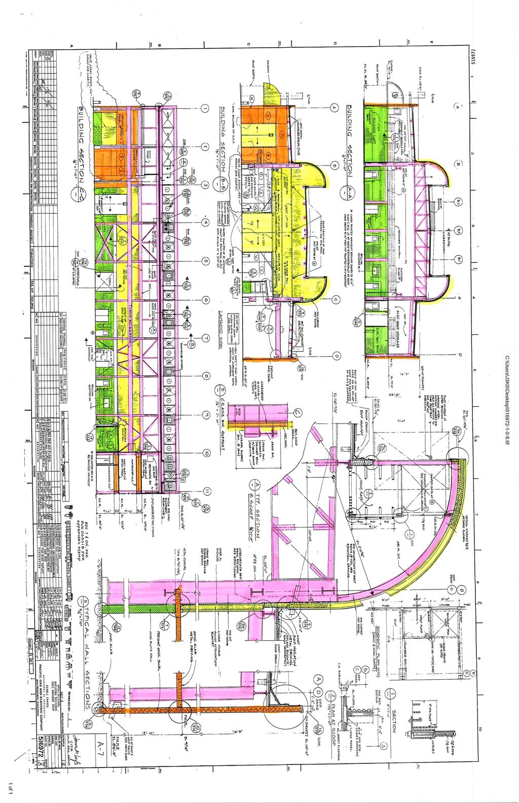
137

138
139 Appendix L: Pathfinder Simulation Figure 63: Simulation 0s from NW Corner Figure 64: Simulation 10s from NW Corner 138

140 Figure 65: Simulation 20s from NW Corner Figure 66: Simulation 30s from NW Corner 139
141 Figure 67: Simulation 40s from NW Corner Figure 68: Simulation 50s from NW Corner 140

142 Figure 69: Simulation 60s from NW Corner Figure 70: Simulation 0s from SE Corner 141
143 Figure 71: Simulation 10s from SE Corner Figure 72: Simulation 20s from SE Corner 142
144 Figure 73: Simulation 30s from SE Corner Figure 74: Simulation 40s from SE Corner 143
145 Figure 75: Simulation 50s from SE Corner Figure 76: Simulation 60s from SE Corner 144
146 Concentration (ppm) Cold Machine Shop FPE 596 Appendix M: Pallet Fire Simulation Time (s) North Exit (West) North Exit (East) East Exit (North) East Exit (Middle) East Exit (South) South Exit (East) South Exit (West) Figure 77: Pallet Fire CO Concentration vs. Time Plot 145


147 Figure 78: Pallet Fire 0s - Top View Figure 79: Pallet Fire 100s - Top View 146
148 Figure 80: Pallet Fire 126s - Top View Figure 81: Pallet Fire 0s - Side View 147
149 Figure 82: Pallet Fire 100s - Side View Figure 83: Pallet Fire - Side View 148


150 Figure 84: Pallet Fire Temperature 0s - Top View Figure 85: Pallet Fire Temperature 100s - Top View 149

151 Figure 86: Pallet Fire Temperature 126s - Top View Figure 87: Pallet Fire Temperature 0s - View from West 150

152 Figure 88: Pallet Fire Temperature 100s - View from West Figure 89: Pallet Fire Temperature 126s - View from West 151
 West Stairwell Southwest Stairwell Southeast Stairwell East Stairwell Figure 90: Office Fire Stairwell CO ppm vs.")
153 CO (ppm) Cold Machine Shop FPE 596 Appendix N: Office Fire Simulation Time (s) West Stairwell Southwest Stairwell Southeast Stairwell East Stairwell Figure 90: Office Fire Stairwell CO ppm vs. Time Figure 91: Office Fire 0s - Top View 152


154 Figure 92: Office Fire 54s - Top View Figure 93: Office Fire 108s - Top View 153
155 Figure 94: Office Fire 180s - Top View Figure 95: Office Fire 0s - View from West 154

156 Figure 96: Office Fire 54s - View from West Figure 97: Office Fire 108s - View from West Figure 98: Office Fire 126s - View from West 155

157 Figure 99: Office Fire Temperature 0s - Top View Figure 100: Office Fire Temperature 54s - Top View 156
158 Figure 101: Office Fire Temperature 108s - Top View Figure 102: Office Fire Temperature 126s - Top View 157

159 Figure 103: Office Fire Temperature 0s - View from West Figure 104: Office Fire Temperature 54s - View from West Figure 105: Office Fire Temperature 108s - View from West 158
By: Russell Bainbridge March 18th, 2016 FPE 596
 By: Russell Bainbridge March 18th, 2016 FPE 596 Egress Analysis and Design California Polytechnic State University's Engineering IV building Fire Detection, Alarm and Communication Systems A warehouse
Construction Warehouse. FPE 596 Culminating Experience In Fire Protection Engineering Final Project (Spring 2014) By Ben Johnson
 By Ben Johnson") Construction Warehouse FPE 596 Culminating Experience In Fire Protection Engineering Final Project (Spring 2014) By Ben Johnson 1 Statement of Disclaimer This project report is a result of a class assignment;
Construction Warehouse FPE 596 Culminating Experience In Fire Protection Engineering Final Project (Spring 2014) By Ben Johnson 1 Statement of Disclaimer This project report is a result of a class assignment;
COSTCO, SAN FRANCISCO A PRESCRIPTIVE AND PERFORMANCE BASED ANALYSIS OF FIRE PROTECTION SYSTEMS AND DESIGN
 COSTCO, SAN FRANCISCO A PRESCRIPTIVE AND PERFORMANCE BASED ANALYSIS OF FIRE PROTECTION SYSTEMS AND DESIGN Presented by Ian Levine June, 2016 Photo courtesy of Google Maps PRESENTATION OVERVIEW BUILDING
Fire Protection System and Life Safety Evaluation of Building X. Anthony W. Sublett
 Fire Protection System and Life Safety Evaluation of Building X Presented by Anthony W. Sublett Culminating Project Master of Science in Fire Protection Engineering California Polytechnic State University
MINOOKA FIRE PROTECTION DISTRICT Fire Prevention Bureau Fire Inspector Rodney Bradberry
 MINOOKA FIRE PROTECTION DISTRICT Fire Prevention Bureau Fire Inspector Rodney Bradberry Fire Alarm Systems Plan Review Checklist Date: Permit Number: Business Name: Address: Fire Alarm System Submittal
Will Clay Spring 2014
 Will Clay Spring 2014 1. Project Overview 2. Prescriptive Requirements 3. Existing Requirements 4. Performance Evaluation 5. Conclusions RJA-Houston since 2010 Hired as FP/LS consultants by architect in
ROBERT E. KENNEDY LIBRARY CAL POLY, SAN LUIS OBISPO FIRE PROTECTION ANALYSIS FPE CULMINATING PROJECT. Prepared For:
 ROBERT E. KENNEDY LIBRARY Page i ROBERT E. KENNEDY LIBRARY CAL POLY, SAN LUIS OBISPO Prepared For: Dr. Frederick W. Mowrer & Dr. Christopher Pascual California Polytechnic State University College of Engineering
Culminating Project. Fire Protection and Life Safety Engineering Analysis. Cal Poly. Center for Science and Mathematics. Fire Protection Engineering
 Culminating Project Fire Protection and Life Safety Engineering Analysis Fire Protection Engineering California Polytechnic State University Center for Science and Mathematics Cal Poly San Luis Obispo,
Construction Innovation Center Building 186
 Construction Innovation Center Building 186 FPE 596 Professors Presented Culminating Experience in Fire Protection Engineering Christopher Pascual & Frederick W. Mowrer Christopher Torres Objective / Overview
Fire Protection Coffee Break Training May 2016
 Fire Protection Coffee Break Training May 2016 Introduction High-Rise Requirements Questions and Answers Agenda Overview Site Fire Access Aerial Access Power/Back-up Power Elevators and Access Sprinklers
Fire Alarm System Fundamentals
 Fire Alarm System Fundamentals Mircom is the largest and oldest privately owned fire alarm and life safety manufacturer in North America and 5th largest overall with 50 years of industry experience. Mircom
Fire Hazard Analysis of Technical Area 53 Building 1
 Fire Hazard Analysis of Technical Area 53 Building 1 June 11, 2015 LA-UR-15-23589 Slide 1 Introduction Brett Noakes Los Alamos National Laboratory Los Alamos, New Mexico Slide 2 Outline Background of the
Fire and Life Safety Analysis
 Fire and Life Safety Analysis Grant M. Brown Engineering Building #41 California Polytechnic State University, San Luis Obispo Daniel Gregory Blanchat June 12 th, 2014 1 B l a n c h a t 1 Statement of
CULMINATING EXPERIENCE IN FIRE PROTECTION ENGINEERING ANALYSIS OF COSTCO, SAN FRANCISCO
 CALIFORNIA POLYTECHNIC STATE UNIVERSITY, SAN LUIS OBISPO CULMINATING EXPERIENCE IN FIRE PROTECTION ENGINEERING ANALYSIS OF COSTCO, SAN FRANCISCO PREPARED BY: IAN LEVINE 380 4 TH AVE SAN FRANCISCO, CA 94118
Fire Protection Analysis DCI Data Center Building
 Fire Protection Analysis DCI Data Center Building California Polytechnic State University FPE 596 Culminating Experience in Fire Protection Engineering Bryan Hathaway M.S. Fire Protection Engineering -
2. The Group F occupancy has have an a combined occupant load of 500 or more above or below the lowest level of exit discharge.
 2. The Group F occupancy has have an a combined occupant load of 500 or more above or below the lowest level of exit discharge. Exception: Manual fire alarm boxes are not required where the building is
FIRE PROTECTION AND SAFETY ANALYSIS FOR AN OFFICE HIGH RISE BUILDING. Fabio Mazza June 2016
 FIRE PROTECTION AND SAFETY ANALYSIS FOR AN OFFICE HIGH RISE BUILDING Fabio Mazza June 2016 Introduction Codes & Standards Building description Performance based design Prescriptive based design Structural
El Reno Fire Department Fire Alarm Plan Review Worksheet
 El Reno Fire Department Fire Alarm Plan Review Worksheet This Fire Alarm Plan Review Checklist is provided as a guide to assist with your Fire Alarm Plan Review Submittal requirements. Please contact us
Type of Fire Alarm Control Panel: System is: Existing OR New If new, provide Electrical Permit Number:
 DATE OF SUBMISSION TO: Department of Licenses and Inspections Commercial and Industrial Fire Inspection Unit 990 Spring Garden Street, 3 rd Floor, Philadelphia, PA 19123 AP# CITY OF PHILADELPHIA FIRE ALARM
SANTA ROSA FIRE DEPARTMENT FIRE PREVENTION BUREAU PLAN REVIEW CHECKLIST FIRE ALARM SYSTEM INSTALLATION
 July 1, 2010 SANTA ROSA FIRE DEPARTMENT FIRE PREVENTION BUREAU PLAN REVIEW CHECKLIST FIRE ALARM SYSTEM INSTALLATION Address: Permit #: Inspector: Date: Status: Inspector: Date: Status: A-Approved; AC-Approved
CALIFORNIA POLYTECHNIC SLO
 CALIFORNIA POLYTECHNIC SLO FIRE PROTECTION ENGINEERING PROGRAM CULMINATING PROJECT SUMMER 2014 ROCK TOLER Statement of Disclaimer This project report is a result of a class assignment; it has been graded
NFPA 72 Code Changes vs 2013
 NFPA 72 Code Changes - 2010 vs 2013 AFAA-NE Westborough, MA February 7, 2018 Richard Roux NFPA 72 National Fire Alarm and Signaling Code Overview and 2013 Changes NFPA 72 1993 Edition Aug 20, 1993 1996
Life Safety Report. XYZ Office Building. Denver Colorado. Prepared by: Keith Dix Monday, June 3, 2013
 Life Safety Report XYZ Office Building Denver Colorado Figure 1 - XYZ Building West Side Prepared by: Keith Dix Monday, June 3, 2013 Culminating Project FPE 596 California Polytechnic University, San Luis
MECKLENBURG COUNTY FIRE MARSHAL S OFFICE
 Effective Date: 11/01/02 Purpose: MECKLENBURG COUNTY To establish a set of guidelines for performance testing of all newly installed or upgraded fire alarm systems in order to ensure that all devices and
PROPOSED CODE CHANGES FOR REVIEW BY THE FIRE CODE ACTION COMMITTEE
 PROPOSED CODE CHANGES FOR REVIEW BY THE FIRE CODE ACTION COMMITTEE Developed by the Midwestern Regional Work Group CONTENTS Item 15 Limited area sprinkler systems Item 20 Scope of IFC Ch 7 Item 21 Fire-resistance-rated
WORKSHEET 2-1 THE MANITOBA RESIDENTIAL OCCUPANCY FIRE RISK INDEX FIRE SAFETY PARAMETER VALUES
 1 WORKSHEET 2-1 THE MANITOBA RESIDENTIAL OCCUPANCY FIRE RISK INDEX FIRE SAFETY PARAMETER VALUES TABLE 2.1 CONSTRUCTION OF STRUCTURAL MEMBERS AND FLOOR AND ROOF (1) ASSEMBLIES (Applies to each fire zone)
New Construction Fire Inspection Process
 New Construction Fire Inspection Process This document is intended to provide the Owner, Designer, and/or Contractor of new construction with an outline of required fire inspections and with the specific
2018 NICET Code Transition Changes
 2018 NICET Code Transition Changes NICET will be transitioning to newer codes accepted in their exams in mid-october 2018, specifically: NFPA 72 2016 NFPA 70 2014 IBC 2015 NFPA 101 2015 Here are some changes
FIRE INSPECTION CHECKLIST
 Applicable Base Codes FIRE INSPECTION CHECKLIST Florida Fire Prevention Code, 5th Edition NFPA 1, Uniform Fire Code, Florida 2012 Edition NFPA 101, Life Safety Code, Florida 2012 Edition NFPA 13, 2010
MOBILE FIRE - RESCUE DEPARTMENT FIRE CODE ADMINISTRATION
 MOBILE FIRE - RESCUE DEPARTMENT FIRE CODE ADMINISTRATION Fire Alarm System Plan Review 2009 International Fire Code and 2010 NFPA 72 Date of Review // BLD201 - Project Address: Project Name: _ Professional
Moreno Valley Fire Department Fire Prevention Bureau. New and Existing Fire Alarm & Signaling Systems Guideline
 Moreno Valley Fire Department Guideline Approved and Authorized By: Adria Reinertson, Fire Marshal Issued: May 8, 2017 Alarm & Signaling Systems PURPOSE Fire alarm and signaling systems are designed to
Human Factors - Egress Analysis for High Hazard Occupancies. Presented by: Michael J. Klemenz, PE, SFPE
 Human Factors - Egress Analysis for High Hazard Occupancies Presented by: Michael J. Klemenz, PE, SFPE Group H Other SFPE presenters today discussed issues relevant to Group H This presentation addresses
Vibratone Horns. Models 350 and 450
 FEDERAL SIGNAL CORPORATION Vibratone Horns Models 350 and 450 DESIGNED FOR ROUTINE SIGNALING Range of up to 200 feet Coded or sustained tones Model 350 12, 24, 120 and 240VAC; Model 450 12, 24, 125 and
Bold items are particular to the City of Euless
 EULESS FIRE DEPARTMENT FIRE MARSHAL S OFFICE INFORMATION LINE: Revised 8/2004 Fire Chief Lee Koontz Fire Marshal Paul Smith EFD-FMO 3-1 2003 International Fire & Building Code as Amended NFPA Standards
TABLE OF CONTENTS GENERAL... 2 A. DEFINITIONS DIGITAL, ADDRESSABLE FIRE ALARM SYSTEM... 2
 Division 28 ELECTRONIC SAFETY AND SECURITY TABLE OF CONTENTS 28 0000 GENERAL... 2 A. DEFINITIONS...2 28 3111 DIGITAL, ADDRESSABLE FIRE ALARM SYSTEM... 2 A. DESIGN REQUIREMENTS...2 B. CONSTRUCTION REQUIREMENTS...2
Fire Alarm and Life Safety System Inspection Certificate
 Fire Alarm and Life Safety System Inspection Certificate For 2018 Sample Inspection Report 123 Main Street Building Phone - (615) 337-9710 Anywhere, State 90009 Tested to NFPA 72 Standards This Inspection
SECTION 907 FIRE ALARM AND DETECTION SYSTEMS
 SECTION 907 FIRE ALARM AND DETECTION SYSTEMS 907.1 General. This section covers the application, installation, performance and maintenance of fire alarm systems and their components in new and existing
DERRY FIRE DEPARTMENT LISTED AGENT CERTIFICATION PROGRAM
 DERRY FIRE DEPARTMENT LISTED AGENT CERTIFICATION PROGRAM THIS COURSE IS FOR AGENTS WISHING TO DISABLE TRANSMITTING SIGNALS IN ORDER TO PERFORM MAINTENANCE TESTING AND DRILLS. OBJECTIVE The objective of
Functional Performance Test
 Fire Alarm Control Panel & Fire Alarm Annunciator Panel Notify all building occupants that testing will be conducted. Fire alarm contractor shall have personnel with 2-way radios at the fire alarm control
Inspector: PROPERTY INFORMATION Photo Smoke Detector Notification Control Panel Stand Alone Smoke Detector Dialer SUMMARY ONLY
 FIRE ALARM INSPECTION AND TESTING SUMMARY PAGE PER 2013 NFPA 72 Inspector: Jim Smith Test Date: 5/22/2014 PROPERTY INFORMATION Name of Property: Windsor Tower Owner of Property: Jim Gibbs Properties Address:
Fire Protection Engineering Culminating Project. Analysis of the Seattle Customer Delivery Center. Prepared by Cynthia Wernet
 Fire Protection Engineering Culminating Project Analysis of the Seattle Customer Delivery Center Prepared by Cynthia Wernet California Polytechnic State University at San Luis Obispo June 9, 2016 Cynthia
Unified Fire Authority - Fire Prevention Bureau
 Unified Fire Authority - Fire Prevention Bureau FIRE ALARM AND EMERGENCY COMMUNICATION SYSTEM RECORD OF COMPLETION To be completed by the system installation contractor at the time of system acceptance
SECTION FIRE ALARM STANDARDS REVISED CONSTRUCTION STANDARD
 PART 1 - GENERAL PURPOSE This Standard is intended to assure that fire detection/alarm systems at The University of Texas at Austin provide the highest level of fire safety possible. SCOPE This standard
EQUIVALENT INITIAL FIRE SAFETY ASSESSMENT
 EQUIVALENT INITIAL FIRE SAFETY ASSESSMENT Factory Plot # 33-36 Sector # 07, Chittagong Chittagong Chittagong 08 Jun 2014 The Alliance for Worker Safety Page 1/18 08 Jun 2014 Introduction to the Report
THE BASICS OF FIRE ALARM PLAN REVIEW
 THE BASICS OF FIRE ALARM PLAN REVIEW Art Shaw A Shaw & Associates, LLC. ashaw@arthurshaw.com 231.838.3269 Fire Protection System Plan Reviewer FP000006 NFPA Certified Plans Examiner 02-0005 NFPA Certified
Fire Safety Evaluation of Existing Manufactured Educational Building Covered by Section 423 of the Florida Building Code
 Walker Engineering, Inc. 833 Rockingham Road Birmingham Alabama 35235-2625 205-854-0160 205-854-0160 (Fax) Fire Safety Evaluation of Existing Manufactured Educational Building Covered by Section 423 of
22A Belvedere Avenue, Parry Sound Sprinkler System Consulting Review
 Parry Sound District Social Services Administration Board Housing and Community Services October 10, 2018 c/o Andrew Ball, Properties and Capital Projects Coordinator Email:aball@psdssab.org 22A Belvedere
University Design Standard Fire Alarm Systems
 1.0 Overview University Design Standard Fire Alarm Systems This document provides Virginia Tech s standards for the design and installation of fire alarm systems and equipment in new construction, retrofit
Project No Belleville Fire Hall/Headquarters and Emergency Operations Centre Section Belleville, Ontario Page 1 of 10
 Belleville, Ontario Page 1 of 10 1 GENERAL 1.1 GENERAL REQUIREMENTS.1 The General Conditions of CCDC2-2008, and the General requirements of Division 1, form part of this Section and must read in conjunction
SECTION DIGITAL, ADDRESSABLE FIRE-ALARM SYSTEM
 SECTION 283111 - DIGITAL, ADDRESSABLE FIRE-ALARM SYSTEM PART 1 - GENERAL 1.1 RELATED DOCUMENTS A. Drawings and general provisions of the Contract, including General and Supplementary Conditions and Division
intelligent solutions
 Alco is one of the leading intelligent solution providers of Fire Detection System. Security System and Public Addressing System in the United States of America. Based in California since 1992, we have
Fire Alarm and Life Safety System Inspection Certificate
 www.fleenorsecurity.com 3 Morgan Court Johnson City, TN 37604 (423) 282-3755 Fire Alarm and Life Safety System Inspection Certificate For Sample Inspection Report 123 Main Street Johnson City, TN 37604
Case Study 1 Underground Car Park
 Case Study 1 Underground Car Park Dorota Brzezińska 1, Janusz Paliszek 2, Piotr Smardz 2, Renata Ollesz 1, Karol Kaczor 2 1 Lodz University of Technology, GRID - Lodz, 2 INBEPO Wroclaw, Poland Building
SANTA ROSA FIRE DEPARTMENT FIRE PREVENTION BUREAU INSPECTION CHECKLIST
 July 1, 2010 SANTA ROSA FIRE DEPARTMENT FIRE PREVENTION BUREAU INSPECTION CHECKLIST FIRE AND LIFE SAFETY SYSTEMS FOR STRUCTURES FIVE OR MORE STORIES IN HEIGHT AND LESS THAN 75 FEET IN HEIGHT FROM THE POINT
Residential Care Facilities Requirements
 Development Services Department Building Division 311 Vernon Street Roseville, California 95678-2649 Residential Care Facilities Requirements SUBMITTAL REQUIREMENTS: Note: These requirements are in addition
A. Hydraulic calculations shall be prepared in accordance with Chapter 23 of NFPA 13 with the following exceptions:
 SECTION 21 13 13 WET-PIPE FIRE SPRINKLER SYSTEM PART 1 - GENERAL 1.1 RELATED DOCUMENTS: A. The Conditions of the Contract and applicable requirements of Division 1, "General Requirements", and Section
System Test Report CLEAN AGENT
 City of Black Hawk Fire Department 196 Clear Creek Street PO Box 68 Black Hawk, CO 80422-068 Office 303-582-0426 Fax 303-582-2229 www.cityofblackhawk.org System Test Report CLEAN AGENT Occupancy Information
CHAPTER 7 ALTERATIONS LEVEL
 CHAPTER 7 ALTERATIONS LEVEL 2 SECTION 701 GENERAL 701.1 Scope. Level 2 alterations as described in Section 404 shall comply with the requirements of this chapter. Exception: Buildings in which the reconfiguration
CubeSmart Gulf Breeze Storage AUTOMATIC FIRE SPRINKLER SYSTEM
 SECTION 21 0000 AUTOMATIC FIRE SPRINKLER SYSTEM PART 1 GENERAL 1.1 QUALITY ASSURANCE A. Codes and Standards: 1. FBC (Florida Building Code 2015) 2. FBC (Florida Fire Code 2015) 3. NFPA #13R (Standard for
Fire Sprinkler Plan Submittal Form
 Contents Fire Sprinkler Plan Submittal Form... 2 Standpipe Plan Review Submittals... 4 Fire Pump Plan Submittal Requirements... 6 Fire Alarm Plan Submittal Form... 8 Kitchen Hood Wet Chemical Submittal...10
Chapter 4: Fire Protection Systems
 Chapter 4: Fire Protection Systems Automatic Extinguishing Systems (Fire Sprinklers) One of the most important aspects of a storage warehouse inspection is ensuring that the automatic extinguishing system
MS-4012/4024 and CMS-4012/4024. Instruction Manual for the. Fire Alarm Control Panels
 R 12 Clintonville Road, Northford, CT 06472 Phone: (203) 484-7161 FAX: (203) 484-7118 Instruction Manual for the MS-4012/4024 and CMS-4012/4024 Fire Alarm Control Panels Document 15586 5/11/93 Revision:
Fire Alarm and Life Safety System Inspection Certificate
 Fire Alarm and Life Safety System Inspection Certificate For Sample Inspection Report 123 Main Street Anywhere, USA 30303 Tested to NFPA 72 Standards This Inspection was performed in accordance with applicable
APPENDIX H (DESIGN SUBMISSION CRITERIA)
") APPENDIX H (DESIGN SUBMISSION CRITERIA) FIRE ALARM SYSTEM As per ACCORD standard Part 5, section 5.7 Fire Alarm System Design to be verified by ACCORD Chief Safety Inspector. Testing of the installation
APPENDIX H (DESIGN SUBMISSION CRITERIA) FIRE ALARM SYSTEM As per ACCORD standard Part 5, section 5.7 Fire Alarm System Design to be verified by ACCORD Chief Safety Inspector. Testing of the installation
Changes in NFPA
 Changes in NFPA 72-2002 2002 Oregon Fire Code Committee November 25, 2003 Michael B. Baker, SET Automatic Fire Alarm Association MikeBaker@afaa.org 2003 Michael B. Baker 1 Table of Contents 1. Administration
Riverside County Fire Department Office of the Fire Marshal Market St., Ste. 150, Riverside, CA Ph. (951) Fax (951)
 Fax (951)") Riverside County Fire Department Office of the Fire Marshal 2300 Market St., Ste. 150, Riverside, CA 92501 Ph. (951) 955-4777 Fax (951) 955-4886 Guideline Title: Residentially Based Care Facilities Group
Riverside County Fire Department Office of the Fire Marshal 2300 Market St., Ste. 150, Riverside, CA 92501 Ph. (951) 955-4777 Fax (951) 955-4886 Guideline Title: Residentially Based Care Facilities Group
Statue of Liberty: A Risk Analysis
 Statue of Liberty: A Risk Analysis Bruce Campbell, FSFPE VP DOE Services National Park Service Agenda Overview of Project Scope Evaluation Steps Task 1 Code Analysis Task 2 Fire Modeling Task 3 Egress
INITIAL FIRE SAFETY ASSESSMENT
 INITIAL FIRE SAFETY ASSESSMENT Dhanpur, Chapapur, Kotwali, Comilla COMILLA Chittagong The Alliance for Worker Safety Page 1/16 Introduction to the Report The following report contains a site profile and
NFPA Changes
 Chapter 21, Emergency Control Functions and Interfaces Summary. Chapter 21 is new. These requirements were formerly found in Chapter 6, Protected Premises Fire Alarm Systems. The term fire safety function
INITIAL FIRE SAFETY ASSESSMENT - EXPANSION
 INITIAL FIRE SAFETY ASSESSMENT - EXPANSION Hatimara Road, Barenda, Kashimpur, Gazipur, Gazipur Dhaka The Alliance for Worker Safety Page 1/11 30 Oct 2016 Introduction to the Report The following report
INITIAL FIRE SAFETY ASSESSMENT
 INITIAL FIRE SAFETY ASSESSMENT Factory Address: Plot 1175 & 1179, Bashan Sarak, Vogra, PO. National University, Gazipur Sadar, Gazipur Gazipur Dhaka Bangladesh 15 Jun 2016 The Alliance for Bangladesh Worker
PLAN REVIEW CHECKLIST
 PLAN REVIEW CHECKLIST Date Documents Submitted: Log No.: File No.: Property Information Building Name: Building Address: Owner s Name: Owner s Address: Owner s Phone: Fax: E-mail: System Designer/Contractor
RAPID RESPONSE Model RCP-1 Residential Control Panel 1 or 1-1/2 Inch (DN25 or DN40), 175 psi (12,1 bar) General Description
, 175 psi (12,1 bar) General Description") Worldwide Contacts www.tyco-fire.com RAPID RESPONSE Model RCP-1 Residential Control Panel 1 or 1-1/2 Inch (DN25 or DN40), 175 psi (12,1 bar) SECTIONS General Description.... 1 Warnings.... 2 Technical
Worldwide Contacts www.tyco-fire.com RAPID RESPONSE Model RCP-1 Residential Control Panel 1 or 1-1/2 Inch (DN25 or DN40), 175 psi (12,1 bar) SECTIONS General Description.... 1 Warnings.... 2 Technical
as required for residential sprinklers intended for use in dry pipe systems.
 Worldwide Contacts www.tyco-fire.com RAPID RESPONSE Residential Dry Pipe System General Description The TYCO RAPID RESPONSE Residential Dry Pipe System provides a normally dry system for areas subject
12/14/2013. Fire alarm and emergency power SPRINKLER HEAD
 Fire alarm and emergency power SPRINKLER HEAD 1 Alert signal Alarm signal Fire detector Heat detector Smoke detector Smoke alarm 1. Detector locations 1. Fire detector locations (3.2.4.11) 2. Smoke detector
Fire Protection Engineering
 Fire Protection Engineering FPE-596-FINAL REPORT NAME: MICHAEL STEWART DATE: JUNE 6, 2014 Contents Statement of Disclaimer... 5 Acknowledgement... 6 Building Overview & Description... 6 Building Construction
Specification/ Data Sheet
 Specification/ Data Sheet TRITON RP Agent Release Control Panel FEATURES Agent Release Control Panel designed specifically for suppression release operation with: Four initiating device circuits (IDCs)
Florida Building Code Chapter 9 Fire Protection Systems Advanced Course
 Florida Building Code 2010 Chapter 9 Fire Protection Systems Advanced Course 1 Introduction This course will cover specific sections of Chapter 9 that relate to fire alarm systems. While many contractors
Full Service Central Station Fire Alarm Listing Evaluation
 Full Service Central Station Fire Alarm Listing Evaluation Listing Evaluation A UL Listing project includes: 1. Evaluating the central station facility for compliance with UL 827, Central-Station Alarm
RAPID RESPONSE Model RCP-1 Residential Control Panel 1 or 1-1/2 Inch (DN25 or DN40), 175 psi (12,1 bar) General Description.
, 175 psi (12,1 bar) General Description.") Worldwide Contacts www.tyco-fire.com RAPID RESPONSE Model RCP-1 Residential Control Panel 1 or 1-1/2 Inch (DN25 or DN40), 175 psi (12,1 bar) General Description The TYCO RAPID RESPONSE Model RCP-1 Residential
Worldwide Contacts www.tyco-fire.com RAPID RESPONSE Model RCP-1 Residential Control Panel 1 or 1-1/2 Inch (DN25 or DN40), 175 psi (12,1 bar) General Description The TYCO RAPID RESPONSE Model RCP-1 Residential
Balloting Version First Draft NFPA 101 Life Safety Code Proposed 2015 Edition
 Copyright National Fire Protection Association 2013. All rights reserved. This copy is solely for your personal, noncommercial use in connection with participation in the NFPA Standards Development Process.
FIRE AND LIFE SAFETY ANALYSIS PRESCRIPTIVE AND PERFORMANCE BASED APPROACH
 FIRE AND LIFE SAFETY ANALYSIS PRESCRIPTIVE AND PERFORMANCE BASED APPROACH CAL POLY RECREATION CENTER BUILDING # 43 SAN LUIS OBISPO, CALIFORNIA CULMINATING PROJECT REPORT CAL POLY FIRE PROTECTION ENGINEERING
Rancho Cucamonga Fire Protection District Prevention Bureau Standard
 Rancho Cucamonga Fire Protection District Prevention Bureau Standard Title: Fire Alarm and Monitoring Systems Standard # 9-3 Effective: May 2002 Number of Pages: 7 Updated: December 2016 for consistency
Standard for the Installation of Carbon Monoxide (CO) Detection and Warning Equipment
 Detection and Warning Equipment") NFPA 720 2015 Summary Standard for the Installation of Carbon Monoxide (CO) Detection and Warning Equipment TM, 7Oct14 CODE: Title, Standard, not Code Consistent with recent trend at NFPA, this document
NFPA 720 2015 Summary Standard for the Installation of Carbon Monoxide (CO) Detection and Warning Equipment TM, 7Oct14 CODE: Title, Standard, not Code Consistent with recent trend at NFPA, this document
HIGH-RISE RETROFIT ORDINANCES - NO and NO
 INFORMATION BULLETIN / PUBLIC - BUILDING CODE REFERENCE NO.: LAMC 91.8604 Effective: 9-06-90 DOCUMENT NO. P/BC 2002-054 Revised: 4-15-03 Previously Issued As: MGD 88 HIGH-RISE RETROFIT ORDINANCES - NO.
Oxnard Fire Department 360 W. Second Street Oxnard, CA (805) Fax (805)
 Fax (805)") Oxnard Fire Department 360 W. Second Street Oxnard, CA 93030 (805) 385-7722 Fax (805) 385-8009 FIVE YEAR CERTIFICATION REPORT Service and maintenance report for automatic fire extinguishing systems, including
Oxnard Fire Department 360 W. Second Street Oxnard, CA 93030 (805) 385-7722 Fax (805) 385-8009 FIVE YEAR CERTIFICATION REPORT Service and maintenance report for automatic fire extinguishing systems, including
GROUP SR SPECIAL RESIDENCE (ASSISTED SELF-PRESERVATION) OCCUPANCIES
 OCCUPANCIES") [B] APPENDIX SR GROUP SR SPECIAL RESIDENCE (ASSISTED SELF-PRESERVATION) OCCUPANCIES The provisions contained in this appendix are adopted by the Building Codes Division of the State of Oregon SECTION SR101
[B] APPENDIX SR GROUP SR SPECIAL RESIDENCE (ASSISTED SELF-PRESERVATION) OCCUPANCIES The provisions contained in this appendix are adopted by the Building Codes Division of the State of Oregon SECTION SR101
For additional information regarding R-3.1 residential care facilities please contact (951)
") Riverside County Fire Department Fire/Life Safety Inspection Division Riverside Office: 2300 Market St., Ste. 150, Riverside, CA 92501 Ph. (951) 955-4823 Fax (951) 955-4886 Palm Desert Office: 77-933 Las
Riverside County Fire Department Fire/Life Safety Inspection Division Riverside Office: 2300 Market St., Ste. 150, Riverside, CA 92501 Ph. (951) 955-4823 Fax (951) 955-4886 Palm Desert Office: 77-933 Las
CITY OF MADISON FIRE DEPARTMENT (MFD) FIRE PROTECTION SYSTEM PLANS
 FIRE PROTECTION SYSTEM PLANS") CITY OF MADISON FIRE DEPARTMENT (MFD) FIRE PROTECTION SYSTEM PLANS Fire Protection Systems includes the following: Alternate Fire Suppression Systems Atrium Fire Protection Systems Automatic Fire Sprinkler
CITY OF MADISON FIRE DEPARTMENT (MFD) FIRE PROTECTION SYSTEM PLANS Fire Protection Systems includes the following: Alternate Fire Suppression Systems Atrium Fire Protection Systems Automatic Fire Sprinkler
SANTA CLARA COUNTY Winchester Blvd., Los Gatos, CA (408) (408) (fax)
 (408) (fax)") FIRE DEPARTMENT SANTA CLARA COUNTY 14700 Winchester Blvd., Los Gatos, CA. 95032-1818 (408) 378-4010 (408) 378-9342 (fax) www.sccfd.org STANDARD DETAILS & SPECIFICATIONS Spec No C-4 Rev. Date 03/10/10 SUBJECT:
FIRE DEPARTMENT SANTA CLARA COUNTY 14700 Winchester Blvd., Los Gatos, CA. 95032-1818 (408) 378-4010 (408) 378-9342 (fax) www.sccfd.org STANDARD DETAILS & SPECIFICATIONS Spec No C-4 Rev. Date 03/10/10 SUBJECT:
INITIAL FIRE SAFETY ASSESSMENT - EXPANSION
 INITIAL FIRE SAFETY ASSESSMENT - EXPANSION Factory Plot 47-52 & 68-73, KEPZ North Patenga Chittagong Chittagong 06 Mar 2017 The Alliance for Bangladesh Worker Safety Page 1/23 06 Mar 2017 Introduction
INSPECTION AND TESTING FORM
 INSPECTION AND TESTING FORM Date: Time: SERVICE ORGANIZATION Name: Address: Representative: License No.: MONITORING ENTITY Contact: Monitoring Account Ref. No.: TYPE TRANSMISSION McCulloh Multiplex Digital
2015 Recommended Building Code with Amendments. The Executive Committee of the Central Iowa Code Consortium does ordain as follows:
 2015 Recommended with Amendments A resolution of the Central Iowa Code Consortium recommending adoption of the 2015 edition of the International, regulating and governing the conditions and maintenance
LifeAlarm Fire Alarm Controls
 UL, ULC Approved* LifeAlarm Fire Alarm Controls 4009 IDNet NAC Extender for Control with IDNet Communications or Conventional NACs Features Provides additional notification appliance circuit (NAC) capacity
Florida Building Code 2010
 Introduction Florida Building Code 2010 Chapter 9 Fire Protection Systems This course will cover specific sections of Chapter 9 that relate to fire alarm systems. While many contractors are familiar with
University of Houston Master Construction Specifications Insert Project Name SECTION DRY-PIPE FIRE SPRINKLER SYSTEM PART 1 - GENERAL
 SECTION 21 13 16 DRY-PIPE FIRE SPRINKLER SYSTEM PART 1 - GENERAL 1.1 RELATED DOCUMENTS: A. The Conditions of the Contract and applicable requirements of Division 1, "General Requirements", and Section
Protecting Your Property: Well Do You Know Your Fire Fire Systems Systems. Joe Szewczyk, Risk Control Consultant
 Protecting Your Property: Protecting How Well Your Do Property: You Know How Your Well Do You Know Your Fire Fire Systems Systems Joe Szewczyk, Risk Control Consultant Joe Szewczyk, Risk Control Consultant
Fire Alarm Testing and Inspection Report
 Fire Alarm Testing and Inspection Report Property Name: Property Address: Property Manager: Contact: Phone Number: Central Station: Phone Number: PELICAN ISLE II 35 DOCKSIDE RD. NAPLES, FLORIDA 3110 BILL
SANTA ROSA FIRE DEPARTMENT FIRE PREVENTION BUREAU PLAN REVIEW CHECKLIST
 July 1, 2010 SANTA ROSA FIRE DEPARTMENT FIRE PREVENTION BUREAU PLAN REVIEW CHECKLIST TENANT IMPROVEMENTS Address: Permit #: Inspector: Date: Status: Inspector: Date: Status: A-Approved; AC-Approved w/comments;
Agency for Health Care Administration
 Page 1 of 92 FED - K0000 - INITIAL COMMENTS Title INITIAL COMMENTS Type Memo Tag FED - K9999 - FINAL OBSERVATIONS Title FINAL OBSERVATIONS Type Memo Tag FED - KA100 - General Requirements - Other Title