SEPARIX. Technical Documentation. SEPARIX-C/-T and SEPARIX-Control CT. Edition: Version: 5 Art. no.:
|
|
|
- Georgia Pope
- 5 years ago
- Views:
Transcription

1 Technical Documentation SEPARIX SEPARIX-C/-T and SEPARIX-Control CT Edition: Version: 5 Art. no.: FAFNIR GmbH Schnackenburgallee 149 c Hamburg Tel.: +49 / 40 / Fax: +49 / 40 /
2 Table of contents 1 Properties of the SEPARIX system Safety instructions SEPARIX-C interface sensors and SEPARIX-T high-level sensors Design and function of SEPARIX-C L Plus and SEPARIX-C H interface sensors of the SEPARIX-T L Plus and SEPARIX-T H high-level sensors Installation of the SEPARIX-C L Plus and SEPARIX-C H interface sensors of the SEPARIX-T L Plus and SEPARIX-T H high-level sensors Maintenance and cleaning of the SEPARIX-C L Plus and SEPARIX-C H interface sensors of the SEPARIX-T L Plus and SEPARIX-T H high-level sensors Technical Data SEPARIX-Control CT measuring transducer Design and function LEDs Buzzer Membrane buttons Configuration Activation of SEPARIX-C Activation of SEPARIX-T Relay energised Relay acknowledgeable Alarm delay Acknowledge button Test button Alarm buzzer Commissioning Faults and alarms I Contents
3 4.4.1 Overview of fault and alarm causes Acknowledgement of faults or alarms Technical data Function test List of figures List of tables Annex SEPARIX-C EC Declaration of Conformity EC-Type Examination Certificate Instructions SEPARIX-C interface sensor SEPARIX-T EC Declaration of Conformity EC-Type Examination Certificate Instructions SEPARIX-T high-level sensor SEPARIX-Control CT EC-Type Examination Certificate Instructions SEPARIX-Control CT measuring transducer Copyright: Reproduction and translation are permitted only with the written consent of the FAFNIR GmbH. The FAFNIR GmbH reserves the right to make product alterations without prior notice. Contents II
4 1 Properties of the SEPARIX system The SEPARIX system is a warning system that, depending on the version, is able to monitor both the thickness of the oil or light liquid layer in an Oil/Water Separator as well as the level of this fluid. The System consists of the following components: SEPARIX-C L Plus or SEPARIX-C H interface sensor SEPARIX-T L Plus or SEPARIX-T H high-level sensor SEPARIX-Control CT measuring transducer The measuring transducer serves as power supply and signal processing of the sensors. The sensors transmit a signal to the connected measuring transducer whenever the oil / light liquid layer exceeds a defined thickness (interface sensor) or whenever the liquid level in the separator rises above an impermissible threshold (high-level sensor). The measuring transducer then generates alarms so that appropriate measures can be taken to stop contaminants from being discharged into the sewage system. Faults and alarms are signalled visually by LEDs and audibly by a buzzer. The measuring transducer also supports the connection of external alarm transmitters. Two versions of both the interface sensor and the high-level sensor are available. The L version is intended for use exclusively in non-aggressive media, such as water and oil, whereas the H version is suitable for use in aggressive media to which the L version connection cable is not resistant. 2 Safety instructions SEPARIX serves as monitoring the light liquid layer and/or the liquid level in Oil/Water Separators. The system must be used exclusively for this purpose. The manufacturer accepts no liability for any form of damage resulting from improper use. The interface sensors, high-level sensors and measuring transducers have been developed, manufactured and tested in accordance with the latest good engineering practices and generally accepted safety standards. Nevertheless, hazards may arise from their use. For this reason, the following safety instructions must be observed: Do not change or modify the system or add any equipment without the prior consent of the manufacturer. The installation and maintenance of the measuring transducer and the sensors must be carried out only by expert personnel. Specialised knowledge must be acquired by regular training. All installation and maintenance work, with the exception of functional testing, must be carried out with the power disconnected. Page 1/37 SEPARIX-C/-T and SEPARIX-Control CT
5 Installers and service technicians must comply with all applicable safety regulations. This also applies to any local safety and accident prevention regulations which are not stated in this user guide. The sensors are suitable for installation in Ex Zone 0. Observe all applicable rules and regulations for potentially explosive atmospheres. The measuring transducer must be installed outside the Ex Zone. The warning system must be tested at the intervals specified by local regulations. To avoid the risk of electrostatic charge, the SEPARIX-C interface sensors are not permitted to be used in heavy-flowing, non-conducting fluids (e.g. in pipework or stirred tanks). Also for cleaning the SEPARIX-C interface sensors the risk of electrostatic charge must be prevented by the using damp cloths. The SEPARIX-C L Plus interface sensor and the SEPARIX-T L Plus high-level sensor are not permitted to be used in aggressive media. The SEPARIX-C H interface sensor and the SEPARIX-T H high-level sensor are suitable for use in aggressive media, with the exception of concentrated, aromatic hydrocarbons and concentrated, strong oxidising acids and trichloroethylene. The safety instructions in this user guide are marked as follows: If these safety instructions are not observed, it may result in the risk of accident or damage to the SEPARIX system. Useful tips and information in this user guide you should observe, appear in italics and are identified by this symbol. SEPARIX-C/-T and SEPARIX-Control CT Page 2/37
6 3 SEPARIX-C interface sensors and SEPARIX-T high-level sensors 3.1 Design and function of SEPARIX-C L Plus and SEPARIX-C H interface sensors The SEPARIX-C L Plus / SEPARIX-C H interface sensors, in conjunction with the SEPARIX- Control CT measuring transducer, form an automatic warning device for Oil/Water Separators. The warning system responds to a change in the thickness of the oil / light liquid layer. It generates an alarm signal before the automatic closure device shuts off the outlet of the separator due to a high oil / light liquid level. Two versions of the interface sensor are available: The SEPARIX-C L Plus is not permitted to be used in aggressive media. The SEPARIX-C H, however, with the 0.5 m cable protection in the form of a stainless-steel corrugated hose, makes it compatible with aggressive media. Both sensors operate on the capacitive measuring principle: To detect the interface, they use the difference between the relative dielectric constant of water and of light liquids, e.g. oil. Unlike measuring systems that use a punctiform method, measurements with SEPARIX-C are taken over the entire surface of the 6 cm long measuring range. This helps to achieve significant insensitivity to contaminations that could otherwise trigger false alarms. The typical switch point is approximately 40 mm above the sensor tip. Depending on the degree of contamination, it may shift mm upwards (within the safe zone). In the event of heavy contamination, which, due to the nature of operation, cannot always be avoided even with regular maintenance, no false alarm is triggered (without the presence of a light liquid layer). Instead, the alarm is triggered at a slightly reduced layer thickness. The SEPARIX-Control CT measuring transducer powers the sensors and evaluates the sensor signals. Page 3/37 SEPARIX-C/-T and SEPARIX-Control CT
7 167 Corrugated hose Switch point Figure 1: SEPARIX-C H, dimensions Figure 2: SEPARIX-C L Plus, dimensions SEPARIX-C/-T and SEPARIX-Control CT Page 4/37
8 3.1.2 of the SEPARIX-T L Plus and SEPARIX-T H high-level sensors The SEPARIX-T L Plus / SEPARIX-T H high-level sensors, in conjunction with the SEPARIX- Control CT measuring transducer, form an automatic warning device for Oil/Water Separators. The warning system responds to the level of liquid in the separator (whether oil, light liquid or water). It generates an alarm signal whenever the liquid level in the separator rises above an impermissible threshold, e.g. due to reverse flow in the separator outlet, or because the automatic closure device has shut off the outlet of the separator due to a high oil / light liquid layer. Two versions of the high-level sensor are available: The SEPARIX-T L Plus is not permitted to be used in aggressive media. The SEPARIX-T H can be used to monitor aggressive media. Both sensors work without moving parts according to the thermal measuring principle, based on the different thermal conductivity of gases and liquids: A PTC resistor in the sensor tip is heated up by the measuring transducer, which increases the resistance of the PTC resistor if surrounded by gas (e.g. air). As soon as the sensor tip comes into contact with liquid, the resistance of the PTC resistor drops because liquids have a significantly higher thermal conductivity than gases and therefore cool the sensor down. The measuring transducer detects this change in resistance whether it is caused by light liquid or water and triggers an alarm. To avoid damage and disturbances caused by splash water, the sensor tip is protected by the sensor housing, which is slotted and open at the bottom end. The switch point is 35 mm above the lower edge of the sensor housing and is marked by a circular groove on the sensor housing. The SEPARIX-Control CT measuring transducer powers the sensors and evaluates the sensor signals. After turning on the SEPARIX-Control CT, the high-level sensor must heat up first before it is ready for operation. Depending on the ambient temperature this heating phase can last up to 2 minutes. Page 5/37 SEPARIX-C/-T and SEPARIX-Control CT
9 150 appr. 180 Response point 35 Response point 24 Figure 3: SEPARIX-T H, dimensions Figure 4: SEPARIX-T L Plus, dimensions SEPARIX-C/-T and SEPARIX-Control CT Page 6/37
10 3.2 Installation For sensor installation observe the following safety instructions: The installation must be carried out only by expert personnel and in accordance with all applicable safety regulations. This also applies to any local safety and accident prevention regulations which are not stated in this user guide. The sensors are suitable for installation in Ex Zone 0. Observe all applicable rules and regulations for potentially explosive atmospheres (VDE in Germany respectively national installation rules and regulations). For installing, the sensors must be disconnected from power supply of the SEPARIX-C L Plus and SEPARIX-C H interface sensors To avoid the risk of electrostatic charge, the sensors are not permitted to be used in heavy-flowing, non-conducting fluids (e.g. in pipework or stirred tanks). The SEPARIX-C L Plus is not permitted to be used in aggressive media; the SEPARIX-C H is not permitted to be used in concentrated, aromatic hydrocarbons and concentrated, strong oxidising acids and trichloroethylene. The interface sensor (4) is suspended on its cable (7) in the Oil/Water Separator (3), immersed into the fluid to be monitored and in a distance of minimum 100 mm to the separator wall and all separator internal installations (see Figure 5). It should be observed not to install the sensor directly near the separator s inlet because of an increased risk of contamination or disturbance by splashing fluids. The correct fastening method and materials depend on local installation rules and regulations and the material used for the separator (concrete, plastic, metal, etc.). The interface sensor must be installed in such a way that the switch point (5) is undercut at the maximum permissible layer thickness (6). For example, if a light liquid layer of 300 mm or more is to be detected, the switch point of the sensor must be 300 mm below the surface of the fluid. As an adjustment aid, the connection cable can be marked at the appropriate height, e.g. with a cable tie: (1) From the sensor tip, measure 40 mm (switch point) plus the layer thickness and fasten the cable tie to the connection cable as a marking (for example above: 40 mm mm = 340 mm above the sensor tip). (2) Install the interface sensor so that the marking is at the level of the liquid surface. Page 7/37 SEPARIX-C/-T and SEPARIX-Control CT
 (3 x 0.")
11 In separators with an automatic closure device, the SEPARIX-C must be installed at a height above the closure device appropriate to the dimensions and operating conditions of the separator so that the system operator still has enough time to take the necessary measures in the event of an alarm. The interface sensor is equipped with a non-detachable blue cable (7) (3 x 0.5 mm²) (SEPARIX-C L Plus: 5 m long, SEPARIX-C H: 4.5 m long). This cable can be shortened or extended up to 250 m with the use of a junction box (1) suitable for the environmental conditions concerned and an extension cable (2). If used in a potentially explosive atmosphere, the extension cable must not exceed the maximum permissible capacitance and inductance of the measuring transducer (see section 4.5). To avoid disturbances or damage to the sensor or measuring transducer, the selected junction box must offer sufficient protection against the ingress of moisture or fluid in the environmental and operating conditions in which it is used. For connecting the sensor to the measuring transducer, please observe the installation instructions for SEPARIX-Control CT in this or another user guide for compatible FAFNIR measuring transducers. The correct operation of the sensors is guaranteed only in conjunction with a compatible and approved measuring transducer. 1 Junction box 2 Extension cable 3 Oil/Water Separator 4 Interface sensor 5 Switch point 6 Layer thickness 7 Sensor cable Figure 5: SEPARIX-C, installation SEPARIX-C/-T and SEPARIX-Control CT Page 8/37
12 3.2.2 of the SEPARIX-T L Plus and SEPARIX-T H high-level sensors The SEPARIX-T L Plus is not permitted to be used in aggressive media. The high-level sensor is suspended on its cable (6) in the Oil/Water Separator (3) in distance to the inlet because there is an increased risk of contamination or disturbance by splashing fluids (see Figure 6: SEPARIX-T, installation). The correct fastening method and materials depend on local installation rules and regulations and the material used for the separator (concrete, plastic, metal, etc.). The measuring transducer detects when the sensor tip of the connected high-level sensor (5) is immersed into fluid (whether light liquid or water). This response point (4) is marked on the outside of the sensor by a circular groove. The high-level sensor must be installed in such a way that the response point (4) is at the height above which an alarm is to be triggered by a rising liquid level. The high-level sensor is equipped with an undetachable blue cable (6) (2 x 0.5 mm²) with a length of 5 m. This cable can be shortened or extended up to 250 m with the use of a junction box (1) suitable for the environmental conditions concerned and an extension cable (2). 1 Junction box 2 Extension cable 3 Oil/Water Separator 4 Threshold point 5 High-level sensor 6 Sensor cable Figure 6: SEPARIX-T, installation Page 9/37 SEPARIX-C/-T and SEPARIX-Control CT
13 If used in a potentially explosive atmosphere, the extension cable must not exceed the maximum permissible capacitance and inductance of the measuring transducer (see section 4.5). To avoid disturbances or damage to the sensor or measuring transducer, the selected junction box must offer sufficient protection against the ingress of moisture or fluid in the environmental and operating conditions in which it is used. For connecting the sensor to the measuring transducer, please observe the installation instructions for SEPARIX-Control CT in this or another user guide for compatible FAFNIR measuring transducers. The correct operation of the sensors is guaranteed only in conjunction with a compatible and approved measuring transducer. SEPARIX-C/-T and SEPARIX-Control CT Page 10/37
14 3.3 Maintenance and cleaning... For sensor maintenance observe the following safety information: The maintenance must be carried out only by expert personnel and in compliance with all applicable safety regulations. This also applies to any local safety and accident prevention regulations which are not stated in this user guide. The sensors are suitable for installation in Ex Zone 0. Observe all applicable rules and regulations for potentially explosive atmospheres (VDE in Germany respectively national installation rules and regulations). For servicing, the sensors must be disconnected from power supply. To avoid the risk of electrostatic charge, always use a damp cloth to clean the SEPARIX-C L Plus / SEPARIX-C H interface sensors. As the sensor has no moving parts, no special maintenance is required. The sensor needs only to be cleaned routinely as part of regular maintenance, cleaning and clearance work on the separator of the SEPARIX-C L Plus and SEPARIX-C H interface sensors Clean the sensor with a damp cloth to minimise the effects of contaminants that could trigger a false alarm (see section 3.1). Grease-dissolving cleaning agents can be used for heavy contamination. It is recommended to test the sensor whenever it has been cleaned (see section 5) of the SEPARIX-T L Plus and SEPARIX-T H high-level sensors Check the sensor routinely for contamination as part of maintenance work on the separator and after an alarm, and, if necessary, clean it to prevent faulty operation. After an alarm, the sensor tip in particular should be inspected for contamination. If the sensor tip is encrusted with dirt, this can be cleaned away using a soft brush and a greasedissolving cleaning agent. Do not use sharp-edged objects to clean the sensor tip under any circumstances. It is recommended to test the sensor whenever it has been cleaned (see section 5). Page 11/37 SEPARIX-C/-T and SEPARIX-Control CT
15 3.4 Technical Data Interface sensors Explosion protection Certificate Protection class SEPARIX-C L Plus and SEPARIX-C H II 1 G EEx ia IIB T5 TÜV 03 ATEX 2368 X IP68 Dimensions SEPARIX-C H: 28 mm x 728 mm SEPARIX-C L Plus: 28 mm x 195 mm Cable length SEPARIX-C H: 4.5 m SEPARIX-C L Plus: 5.0 m Ambient temperature -20 C +70 C -20 C +60 C (explosion-risk area) Medium temperature 0 C +70 C 0 C +60 C (explosion-risk area) Connection data Voltage: Current: Power: Capacitance (externally effective): Inductance (externally effective): Ui 15 V Ii 30 ma Pi 100 mw Ci 1 nf Li negligibly small High-level sensors Explosion protection SEPARIX-T L Plus and SEPARIX-T H II 1 G EEx ia IIB T3 Certificate TÜV 05 ATEX 2820 Protection class IP68 Dimensions SEPARIX-T H: 24 mm x 180 mm SEPARIX-T L Plus: 16 mm x 278 mm Cable length 5 m Ambient temperature -25 C +60 C Medium temperature -25 C +50 C Connection data Voltage: Current: Power: Capacitance (externally effective): Inductance (externally effective): Ui 30 V Ii 200 ma Pi 1.5 W Ci negligibly small Li negligibly small SEPARIX-C/-T and SEPARIX-Control CT Page 12/37
16 4 SEPARIX-Control CT measuring transducer 4.1 Design and function The SEPARIX-Control CT measuring transducer serves as power supply and signal processing of the connected SEPARIX-C L Plus / SEPARIX-C H interface sensor and/or the SEPARIX-T L Plus / SEPARIX-T H high-level sensor and forms together with the sensors a warning system for Oil/Water Separator. With the interface sensor, the warning system reacts to the thickness of the oil / light liquid layer. It generates an alarm signal before the automatic closure device shuts off the outlet of the separator due to a high oil / light liquid level. With the high-level sensor, the warning system reacts to the fluid height (whether oil, light fluid or water) in the separator. It generates an alarm signal whenever the liquid level in the separator rises above an impermissible threshold, e.g. due to reverse flow of the separator outlet, or because the automatic closure device has shut off the outlet of the separator due to a high oil / light liquid layer. The two connectable sensors can individually be activated or deactivated in the SEPARIX- Control CT. 1: Power LED (green) 2: Fault LED (yellow) 3: Alarm LED (red) 4: Acknowledge button (red) 5: Test button (yellow) Figure 7: SEPARIX-Control CT, top view Faults and alarms are signalled visually by LEDs (1-3) and audibly by a buzzer. Two potentialfree changeover contacts permit the connection of external alarm transmitters and are switched in the event of an alarm. Two membrane buttons (4/5) are used to acknowledge faults and alarms as well as to test the alarm signalling behaviour of the device and, where applicable, connected alarm transmitters. The alarm signalling of the device can be configured individually using the "Options" DIP switch (see section 4.2). Page 13/37 SEPARIX-C/-T and SEPARIX-Control CT
17 4.1.1 LEDs The SEPARIX-Control CT measuring transducer is equipped with three LEDs (see Figure 7). The measuring transducer lamps show different operating states and/or faults: Power LED (green) Fault LED (yellow) Alarm LED (red) blinks repeatedly 1x short if only the interface sensor is activated. blinks repeatedly 2x short if only the high-level sensor is activated. blinks repeatedly 3x short if both sensors are activated. OFF, whenever both sensors are deactivated or the device is out of operation. blinks repeatedly 1x short if there is a fault with the interface sensor. blinks repeatedly 2x short if there is a fault with the highlevel sensor. blinks repeatedly 3x short if there is fault with the interface sensor and the highlevel sensor. blinks repeatedly 1x short if the interface sensor signals an alarm (max. layer thickness reached/exceeded). blinks repeatedly 2x short if the high-level sensor signals an alarm (liquid level too high). blinks repeatedly 3x short if both sensors signal an alarm. OFF, when the cause of the alarm has been rectified. Possible causes: cable break, short circuit, sensor signal outside the permissible range, sensor not working, defect in the sensor evaluation of the measuring transducer, high-level sensor tip encrusted with dirt Buzzer The measuring transducer is equipped with a buzzer that produces an audible signal in the event of a fault or alarm. The acoustic signal will be turned off after pressing the acknowledge button. If desired, the measuring transducer configuration settings allow to deactivate the buzzer so that it no longer sounds (see section 4.2) Membrane buttons The measuring transducer has two membrane buttons: The red acknowledge button (4) confirms faults and alarms signalled by the LEDs and the buzzer (also in test mode). Pressing the button switches OFF the buzzer and the relay output returns to the normal operating state. The LEDs continue to signal the fault or alarm condition. Pressing the yellow test button (5) triggers a simulated alarm to proceed a system test (function of the internal alarm system, the relay outputs and, where applicable, the connected external alarm transmitters). SEPARIX-C/-T and SEPARIX-Control CT Page 14/37
18 A system test is only be possible if the SEPARIX-T high-level sensor has been heated up. If only the test button is pressed, an unacknowledged alarm will be simulated. If both the test and acknowledge buttons are pressed, an acknowledged alarm will be simulated. The test button does not replace the function test of the warning system (see section 5). The measuring transducer configuration settings allow both buttons to be locked, e.g. in cases where the measuring transducer is part of a central control system and the system operator shall not acknowledge any faults or carry out any tests (see section 4.2). 4.2 Configuration The measuring transducer is factory preconfigured and ready for operation. With the help of the "Options" DIP switch you are able to configure SEPARIX-Control CT (see following table): Option DIP switch OFF DIP switch ON 1 SEPARIX-C OFF ON * 2 SEPARIX-T OFF ON * 3 Relay energised Alarm * No alarm 4 Relay acknowledgeable Yes * No 5 Alarm delay 60 sec. * No 6 Acknowledge button Locked Unlocked * 7 Test button Locked Unlocked * 8 Alarm buzzer Locked Unlocked * * : Default factory setting Table 1: SEPARIX-Control CT, configuration Page 15/37 SEPARIX-C/-T and SEPARIX-Control CT
19 Figure 8: SEPARIX-Control CT, terminals and "Options" DIP switch Activation of SEPARIX-C With switch 1, the SEPARIX-C interface sensor is activated. The Power LED indicates whether the sensor is activated or deactivated (see section 4.1.1). The sensor is activated by default. Whenever both sensors will be deactivated, the device is no longer operational and the Power LED (see Figure 7) is OFF Activation of SEPARIX-T With switch 2, the SEPARIX-T high-level sensor is activated. The Power LED indicates whether the sensor is activated or deactivated (see section 4.1.1). The sensor is activated by default. Whenever both sensors will be deactivated, the device is no longer operational and the Power LED (see Figure 7) is OFF Relay energised With switch 3, it is configured whether the relay is energised in case of a fault/alarm or if it is energised in normal operation. By factory default the relay is set energised in case of a fault/alarm Relay acknowledgeable With switch 4 the relay is configured whether it can be acknowledged and reset in case of a fault/alarm with the red acknowledge button. Otherwise, the relay is reset only, if the cause of the fault/alarm is corrected. By factory default the relay is set acknowledgeable. SEPARIX-C/-T and SEPARIX-Control CT Page 16/37
20 4.2.5 Alarm delay With switch 5, the alarm delay is configured. By factory default the alarm delay is activated (60 seconds). A fault or alarm is triggered only if the cause of the fault/alarm is present for at least 60 seconds. The same applies to the switching off of fault or an alarm: they switch off 60 seconds after the cause of the fault or alarm has been corrected. The alarm delay is intended to prevent false alarms, which e.g. could occur by waves or splash water in the separator. The alarm delay can be deactivated, e.g. for demonstration purposes. For normal operation, however, it is strongly recommended to have the alarm delay activated in order to prevent false alarms Acknowledge button With switch 6, the red acknowledge button is configured. By factory default the acknowledge button is set enabled, so that the fault or alarm can be acknowledged by the system operator. The button can be locked if an acknowledgement by the system operator is not required. In this case, the unacknowledged state will persist until the cause of the fault or alarm has been corrected Test button With switch 7, the test button is configured. By factory default the yellow test button is set enabled so that an alarm can be simulated and any connected external alarm transmitters can be tested. If this test mode capability is not required for the system operator, it is possible to lock the button Alarm buzzer With switch 8, the alarm buzzer is configured. By factory default the internal alarm buzzer is set enabled so that an audible signal is given for faults and alarms. If an audible signal is not required, it is possible to disable the buzzer. 4.3 Commissioning Observe the following safety information for commissioning of the measuring transducer: The installation must be carried out only by expert personnel and in accordance with all applicable safety regulations. This also applies to any local safety and accident prevention regulations which are not stated in this user guide. The measuring transducer must not be installed within the potentially explosive atmosphere. The wiring must be carried out with the power disconnected. Page 17/37 SEPARIX-C/-T and SEPARIX-Control CT
21 Install the measuring transducer in accordance with the connection diagram on the inside of the device cover. Observe the maximum operating parameter values specified in the connection diagram (see Figure 8). (1) Check the configuration of the measuring transducer and correct if necessary (see section 4.2). (2) Whichever applicable, connect the SEPARIX-C H or SEPARIX-C L Plus interface sensor to the measuring transducer according to the connection diagram. (3) Whichever applicable, connect the SEPARIX-T H or SEPARIX-T L Plus high-level sensor to the measuring transducer according to the connection diagram. If a shielded cable is used, this must be earthed in accordance with national or local installation rules and regulations. (4) Whichever applicable, connect external alarm devices to the terminals 6 to 8 (interface relay output) and 9 to 11 (high level relay output) of the SEPARIX-Control CT measuring transducer. (5) Connect the measuring transducer to an auxiliary power unit of 230 V AC, 50/60 Hz, using the terminals marked PE/N/L. The green "Power" LED of the SEPARIX-Control CT blinks. The warning system is operational. The SEPARIX-Control CT measuring transducer with a connected SEPARIX-T high-level sensor is operational after the sensor has heated up. According to the ambient temperature this heating phase can last up to 2 minutes. (6) Inform owner and/or system operator about the purpose of the warning system and, where applicable, of any additional alarm transmitters that have been connected. Point out all aspects specific to the present arrangement, particularly if the measuring transducer's default factory settings have been changed (e.g. acknowledge button disabled). Also instruct them how to act in the event of a fault or an alarm (e.g. acknowledge alarms and faults, customer service phone no. in the event of an alarm, etc.). SEPARIX-C/-T and SEPARIX-Control CT Page 18/37
22 4.4 Faults and alarms In case of a fault or an alarm the factory-set SEPARIX-Control CT triggers with the buzzer an audible alarm signal. In case of a fault, additionally the yellow fault LED blinks, and with an alarm, additionally the red alarm LED blinks Overview of fault and alarm causes 1: Power LED (green) 2: Fault LED (yellow) Power Error Alarm Oil layer sensor Overfill sensor.... Oil layer + overfill 3: Alarm LED (red) 4: Acknowledge button (red) 5: Test button (yellow) Figure 9: SEPARIX-Control CT, fault and alarm display Blink code Power LED (green) Fault LED (yellow) Alarm LED (red) 1x short Interface sensor Interface sensor Oil layer 2x short High-level sensor High-level sensor High level 3x short Interface sensor and high-level sensor Interface sensor and high-level sensor Oil layer and high level Acknowledgement of faults or alarms Press red acknowledge button. The fault or alarm is acknowledged and the buzzer stops. The yellow or red LED continues to blink because the cause of the fault or alarm has not yet been corrected. Faults and alarms are repeated every 24 hours after they have been acknowledged (red acknowledge button pressed) so that they are brought to the system operator's attention again. Page 19/37 SEPARIX-C/-T and SEPARIX-Control CT
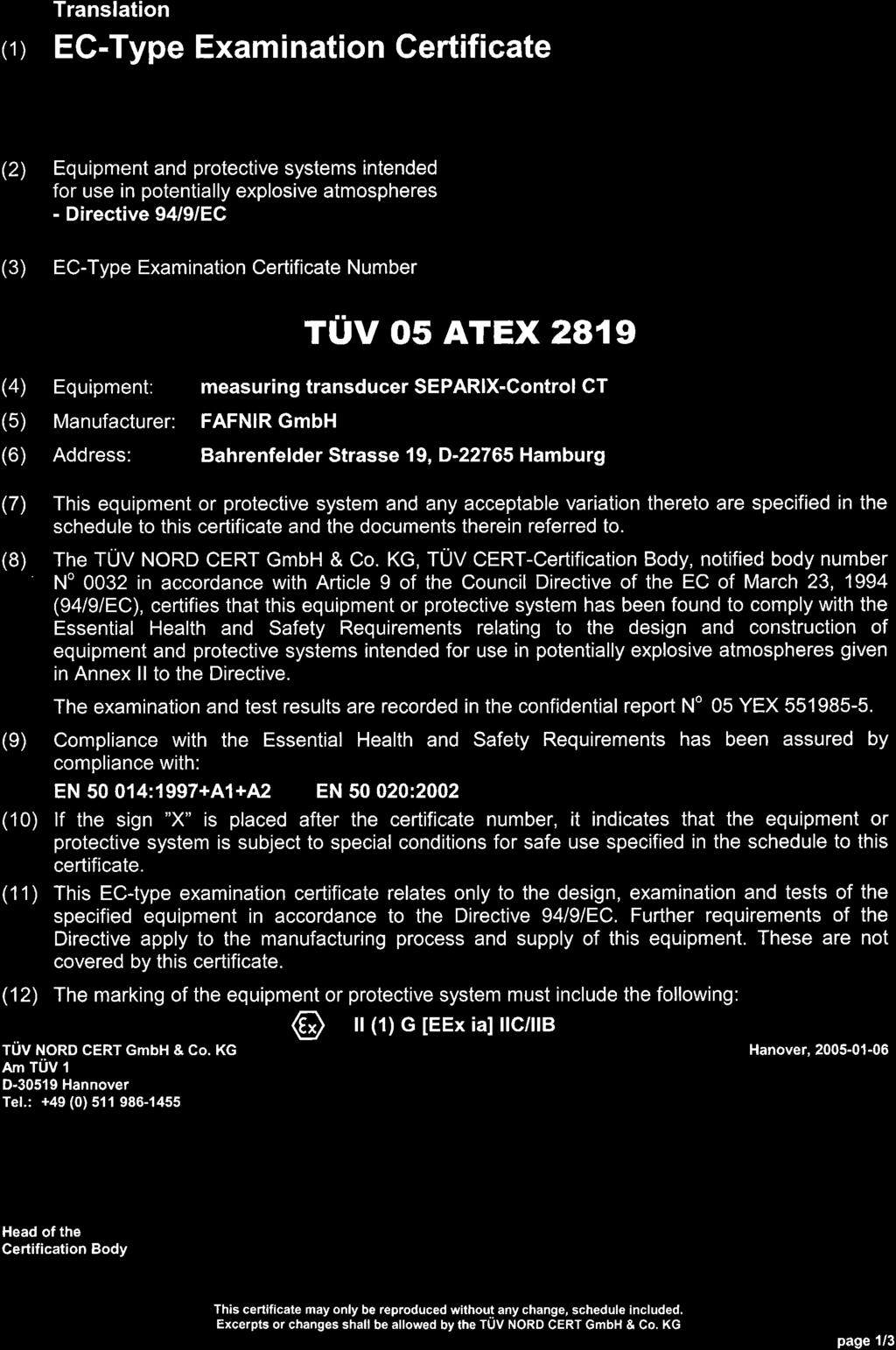
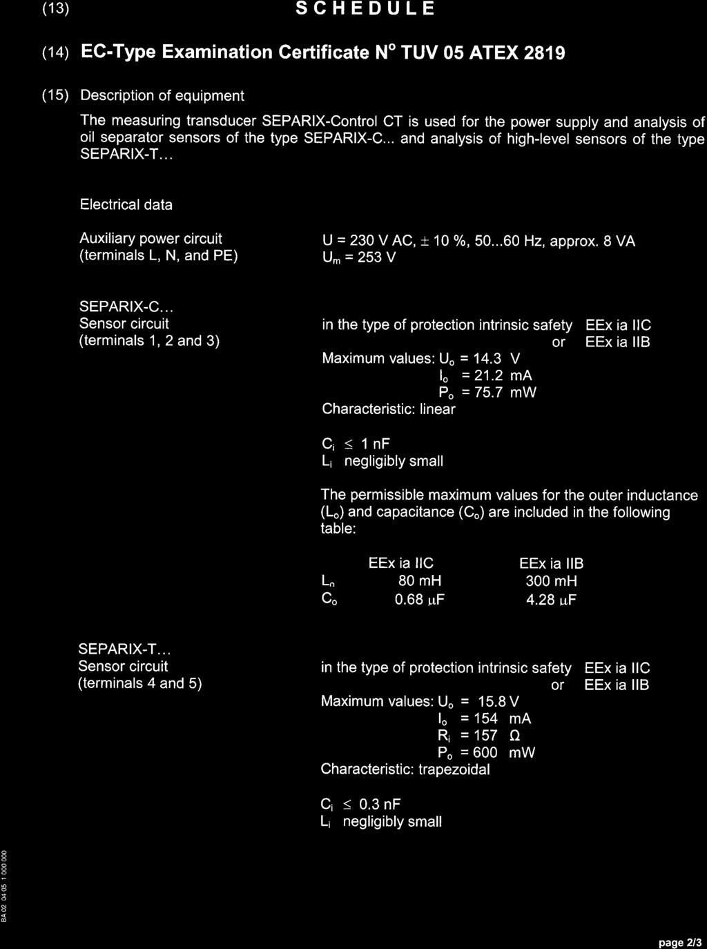
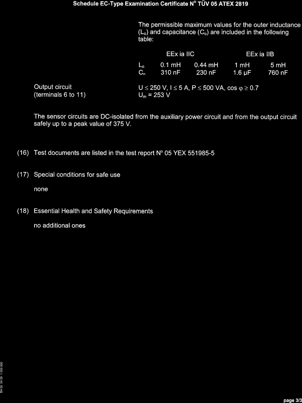
23 Inform the technical service responsible for the oil / light liquid separator. The yellow or red LED will stop blinking as soon as the cause of the fault or alarm has been corrected by the technical service. As the configuration of the warning system may have been customised for the specific application (e.g. disable acknowledge button) or additional external alarm transmitters may have been connected, you should ask the technical service to explain how to acknowledge the faults and alarms in your particular system arrangement. 4.5 Technical data Measuring transducer Explosion protection SEPARIX-Control CT II (1) G [EEx ia] IIC/IIB Certificate TÜV 05 ATEX 2819 Dimensions (H x W x D) Protection class 155 mm x 180 mm x 60 mm IP65 Ambient temperature 0 C +40 C Auxiliary power Connection data Relay circuit Connection data SEPARIX-C sensor circuit: Voltage: Current: Power: Internal resistance: Capacitance (externally effective): Inductance (externally effective): External capacitance: External inductance: Connection data SEPARIX-T sensor circuit: Voltage: Current: Power: Internal resistance: Capacitance (externally effective): Inductance (externally effective): External capacitance: External inductance: 230 V AC ± 10%, 50/60 Hz, 8 VA AC: U 250 V, I 5 A, P 500 VA, cos ϕ 0.7 DC: U 250 V, I 250 ma, P 50 W U V I ma P mw Ri 673 Ω Ci 1 nf Li negligibly small IIC IIB C0 680 nf 4.28 μf L0 80 mh 300 mh U V I0 154 ma P0 600 mw Ri 157 Ω Ci 0.3 nf Li negligibly smaall IIC IIB C0 230 nf 310 nf 760 nf 1.6 μf L0 440 μh 100 μh 5 mh 1 mh SEPARIX-C/-T and SEPARIX-Control CT Page 20/37
24 5 Function test For the function test of the SEPARIX-C L Plus and SEPARIX-C H interface sensors: (1) First remove the interface sensor from the separator fluid. (2) Clean the sensor (see section 3.3) Water or watery dirt are removed 1. (3) Place the sensor on a dry and non-metallic surface. As the sensor behaves in the same way in air as in light liquid, the measuring transducer must trigger the appropriate alarm signal 3 after the adjusted alarm delay time 2 set on the transducer (default setting 1 minute). (4) As a counter check, immerse the interface sensor in water. After expiration of the alarm delay time 2 (default setting 1 minute), the alarm signal at the measuring transducer must revert to its original state 3. For the function test of the SEPARIX-T L Plus and SEPARIX-T H high-level sensors: (1) First remove the high-level sensor from the separator. (2) Check the sensor for dirt and clean it if necessary (see section 3.3). (3) To test the sensor, immerse it in water. After the alarm delay time set on the measuring transducer 2 (default setting 1 minute), the appropriate alarm signal 3 must be triggered by the measuring transducer. (4) As a counter check, remove the high-level sensor from the water. After the sensor has heated up again, the alarm signal at the measuring transducer must revert to its original state 3. In addition to the alarm delay time set on the measuring transducer 2, it can take up to 2 minutes for the sensor to reheat, depending on ambient temperature. 1 Whenever the sensor is removed from the separator, the sensor has been contaminated with watery dirt in the course of time. It is necessary to clean the sensor so that it responds quickly during the test. Otherwise, depending on the degree of contamination, it could take several hours before an alarm is triggered, i.e. until the water evaporates and the dirt has dried. The same applies if the dirty sensor is immersed in light liquid. In this case, the light fluid has to displace the water from the dirt first, which can also take several hours. 2 The measuring transducer delays the triggering and clearance of the alarm in order to prevent false alarms caused by occasional wave movements or splash of fluids. The measuring transducer configuration settings allow the alarm delay to be deactivated for test or demonstration purposes. For normal operation, the alarm delay of the measuring transducer should always remain activated in order to prevent false alarms. Page 21/37 SEPARIX-C/-T and SEPARIX-Control CT
25 3 Normally, the measuring transducer triggers an alarm whenever the interface sensor is in air/light fluid, or whenever the level sensor is in fluid. For custom applications, measuring transducer configuration settings make it possible to invert the alarm triggering so that an alarm is triggered whenever the interface sensor is in water or the high-level sensor is in air. In cases of doubt, check whether the measuring transducer has been configured correctly for the application concerned. 6 List of figures Figure 1: SEPARIX-C H, dimensions... 4 Figure 2: SEPARIX-C L Plus, dimensions... 4 Figure 3: SEPARIX-T H, dimensions... 6 Figure 4: SEPARIX-T L Plus, dimensions... 6 Figure 5: SEPARIX-C, installation... 8 Figure 6: SEPARIX-T, installation... 9 Figure 7: SEPARIX-Control CT, top view Figure 8: SEPARIX-Control CT, terminals and "Options" DIP switch Figure 9: SEPARIX-Control CT, fault and alarm display List of tables Table 1: SEPARIX-Control CT, configuration SEPARIX-C/-T and SEPARIX-Control CT Page 22/37


26 FAFNIR EG - Konformitätserklärung EC - Declaration of Conformity In Übereinstimmung mit EN ; In accordance with EN ; 1998 FAFNIR GmbH Bahrenfelder Str. 19 D Hamburg erklärt in eigener Verantwortlichkeit, daß das Produkt declare under sole responsibility that the product Trennschichtsensor mit Messumformer Oil Layer Sensor with Measuring Transducer SEPARIX-C... I SEPARIX-Control C in Übereinstimmung mit nachfolgenden Richtlinien: in accordance with the following directives: EMV-Richtlinie; EMC Directive 89/336/EWG/EEC Ex-Richtlinie; Ex Directive 94/9/EG/EC nach folgenden Vorschriften (Normen) entwickelt und gefertigt wurden: has been designed and manufactured to the following specifications: EN ; 1997+A1+A2 EN ,2001 EN ; 2002 EN ; 2001 EN ; 1999 EN ; 2001 EN ; 2001 EN ; 2001 EN ; 2001 EN , Klasse B Das Produkt entspricht der EG-Baumusterprüfbescheinigung The above mentioned product is in conformity with EC-Type Examination Certivicate TÜV 03 ATEX 2368 X I TÜV 03 ATEX 2369 Die Prüfung erfolgte durch die benannte Stelle Nr.: 0032 The inspection was carried out by the notified body No 0032 TÜV Hannover/Sachsen-Anhalt e.v. TÜV Cert-Zertifizierungsstelle Am TÜV 1 D Hannover Hamburg, Ort, Datum I Place, Date Geschäftsführer I Managing Director: S. Kunter
27
28

29 Instructions in accordance with Directive 2014/34/EU TÜV 03 ATEX 2368 X Interface sensor Type SEPARIX-C Edition: I Range of application The interface sensor is used as part of a monitoring system for oil/water separators and serves for the detection of an interface between water and light liquids. When the layer thickness of the light liquid reaches the switching point of the sensor, an alarm signal is produced via the associated measuring transducer. II Standards The equipment is designed in accordance with the following European standards EN : A11:2013 EN :2012 Equipment - General Requirements Equipment protection by intrinsic safety "i" III Instructions for safe III.a use The interface sensor sensor is designed as intrinsically safe apparatus and is approved for use in potentially explosive areas. The sensor may be used for gas groups IIA and IIB. The approval applies to the device versions SEPARIX-C H Enclosure and cable protection for aggressive media SEPARIX-C L Plus Enclosure for non-aggressive media III.b assembling and dismantling Dismantling of the interface sensor is not provided. Dismantling would also damage the interface sensor and invalidate the approval. III.c installation All wiring operations must be carried out with the power disconnected. Special rules and regulations, including EN and local installation regulations, must be observed. The interface sensor is suspended from its cable immersed in the liquid to be monitored. The sensor must be installed so that the switching point is (below the liquid surface) at the level at which the alarm is to be signalled as soon as any light liquid occurs there. The interface sensor version 1 is equipped with a permanently connected blue cable (3 0.5 mm²). This cable is allowed to be shortened or lengthened. For cable extensions, a suitable junction box for the respective ambient conditions must be used. Version 2 is equipped with an M12 connector. When wiring the interface sensor to the measuring transducer (preferably blue coloured cable), the permissible inductance and capacitance must not be exceeded. The connection to the measuring transducer has to be proceeded in accordance to the measuring transducer instructions. Version 1 Version 2 Colour Wire Pin Wire M12-Cable (Female) White Power supply + 1 Power supply + Green Frequency signal 2 A / frequency signal Brown Power supply - 3 Power supply - Table III.c: Terminal assignment of the sensor 4 B The integration of the interface sensor into the equipotential bonding is not required. Page 1/2 FAFNIR GmbH Schnackenburgallee 149 c Hamburg Tel: +49 / (0)40 / info@fafnir.de
30 III.d adjustment For operating the interface sensor no Ex-relevant adjustments are required. III.e putting into service Before putting into service, all devices must be checked of right installation and connection. The electrical supply, as well of connected devices, must be checked. III.f maintenance (servicing and emergency repair) As part of regular maintenance of the Oil/Water Separator, the interface sensor must thoroughly be cleaned using a moist cloth. Grease-dissolving cleansing agents can be used to remove any firmly clinging grease or oil residues. Sharp-edged objects are unsuitable for the purpose of cleaning since they could damage the sensor. In case of a defect, the interface sensor must be sent back to FAFNIR or one of its representatives. There is compliance with the requirements for the dielectric strength between the intrinsically safe circuit and the chassis of the interface sensor with 500 V AC in accordance with EN , section IV Equipment marking 1 Manufacturer: FAFNIR GmbH, Hamburg 2 Type designation: SEPARIX-C 3 Certificate number: TÜV 03 ATEX 2368 X 4 Ex marking: II 1 G Ex ia IIB T4 Ga 5 CE marking: Technical Data U i 15 V L i < 100 µh I i 30 ma C i < 10 nf P i 100 mw T a +60 C V Page 2/2 Technical data The safety-related values are defined with: Input voltage U i 15 V Input current I i 30 ma Input power P i 100 mw The externally effective capacitance and inductance are: Internal capacity Internal inductance C i 10 nf L i 100 μh The interface sensor may be used in the following temperature ranges: Ambient temperature -20 C T a +60 C Medium temperature 0 C T F +60 C General information (see also EN , section 1): Zone 0 exists only under atmospheric conditions: Temperature range -20 C +60 C Pressure range 0,8 bar 1,1 bar Oxidants Air (oxygen content approx. 21 %) The interface sensor achieves a degree of protection provided by enclosure: VI None. Degree of protection IP68 Specific conditions for use FAFNIR GmbH Schnackenburgallee 149 c Hamburg Tel: +49 / (0)40 / info@fafnir.de

31

32
33
34 Instruction manual high-level sensor type SEPARIX-T L / -T H As of: Description The high-level sensor, type SEPARIX-T L / -T H, consists of a probe, which is provided with a permanently connected cable and is permanently installed or suspended above the run-off level in a light liquid separator and also carries a detector (steel-encapsulated PTC resistor) protected at its bottom end. The high-level sensor type SEPARIX-T L is made of brass. The high-level sensor type SEPARIX-T H is made of stainless steel and is also suitable for use in aggressive media. 2 Mode of operation The high-level sensor is used in light liquid separators and serves the purpose of detecting a build-up of liquid inside the separator. A PTC resistor, which is heated up by the respective measuring transducer, is used as a detector element. The resistance of the PTC resistor changes as a result of the heating-up process. If the sensor is in liquid (light liquid as well as water), it can no longer be heated up to a specific temperature because of the increased dissipation of heat, and the measuring transducer signals an alarm. 3 Installation The high-level sensor is permanently installed or suspended inside the separator at the desired threshold height (liquid level at which the alarm is to be triggered). The precise threshold point is marked on the outside of the sensor. Wiring work may only be performed with the equipment in de-energized condition. The special VDE regulations and the local installation regulations must be observed. The high-level sensor is equipped with a permanently connected blue cable (2 x 0.5 mm²). This cable is not allowed to be shortened or lengthened. For cable extensions, a suitable distribution box for the respective ambient conditions must be used. The connection to the measuring transducer must be made according to the instruction manual of the measuring transducer. 4 Operating instructions The oil separator sensor, including in particular the detector tip, must be properly cleaned within the framework of regular maintenance and after every alarm. Grease-dissolving cleansing agents can be used to remove any firmly clinging grease or oil residues. Sharp-edged objects are unsuitable for the purpose of cleaning since they could damage the sensor. Before being put into service, all devices must be checked with respect to correct connection and proper operation. The electrical power supply, including the supply of the downstream devices, must be checked. The general operating instructions for the devices being used must be observed. Page 1/2 FAFNIR GmbH Bahrenfelder Str. 19 D Hamburg Phone: +49 / (0) 40 / Fax: +49 / (0) 40 /
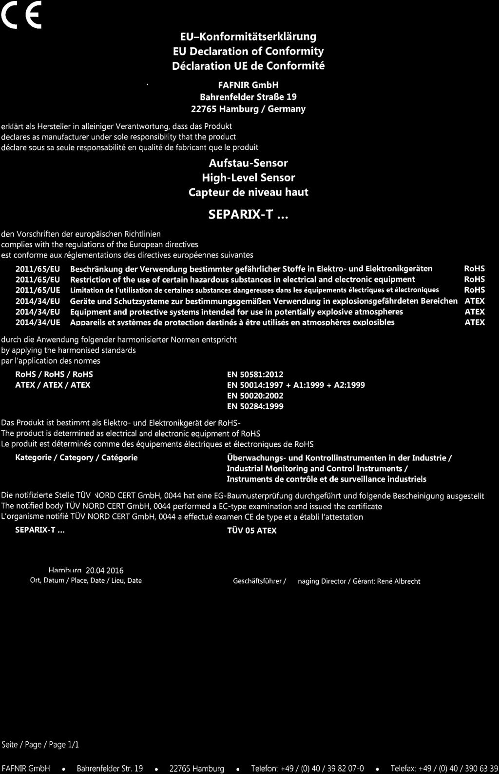
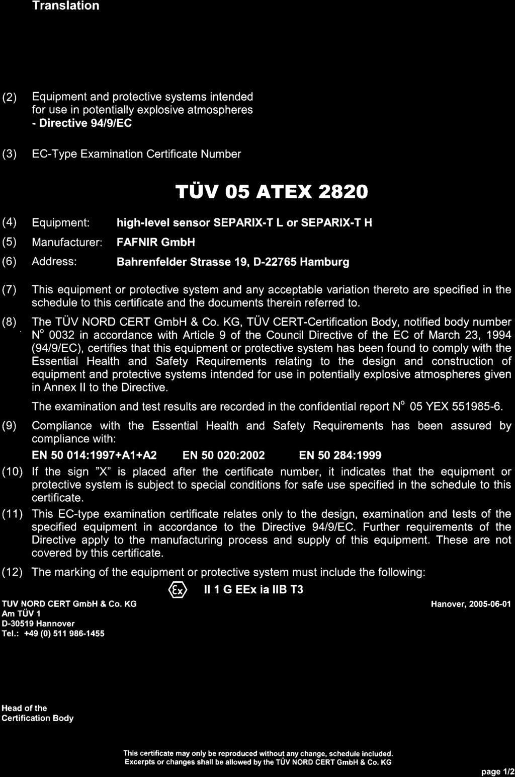
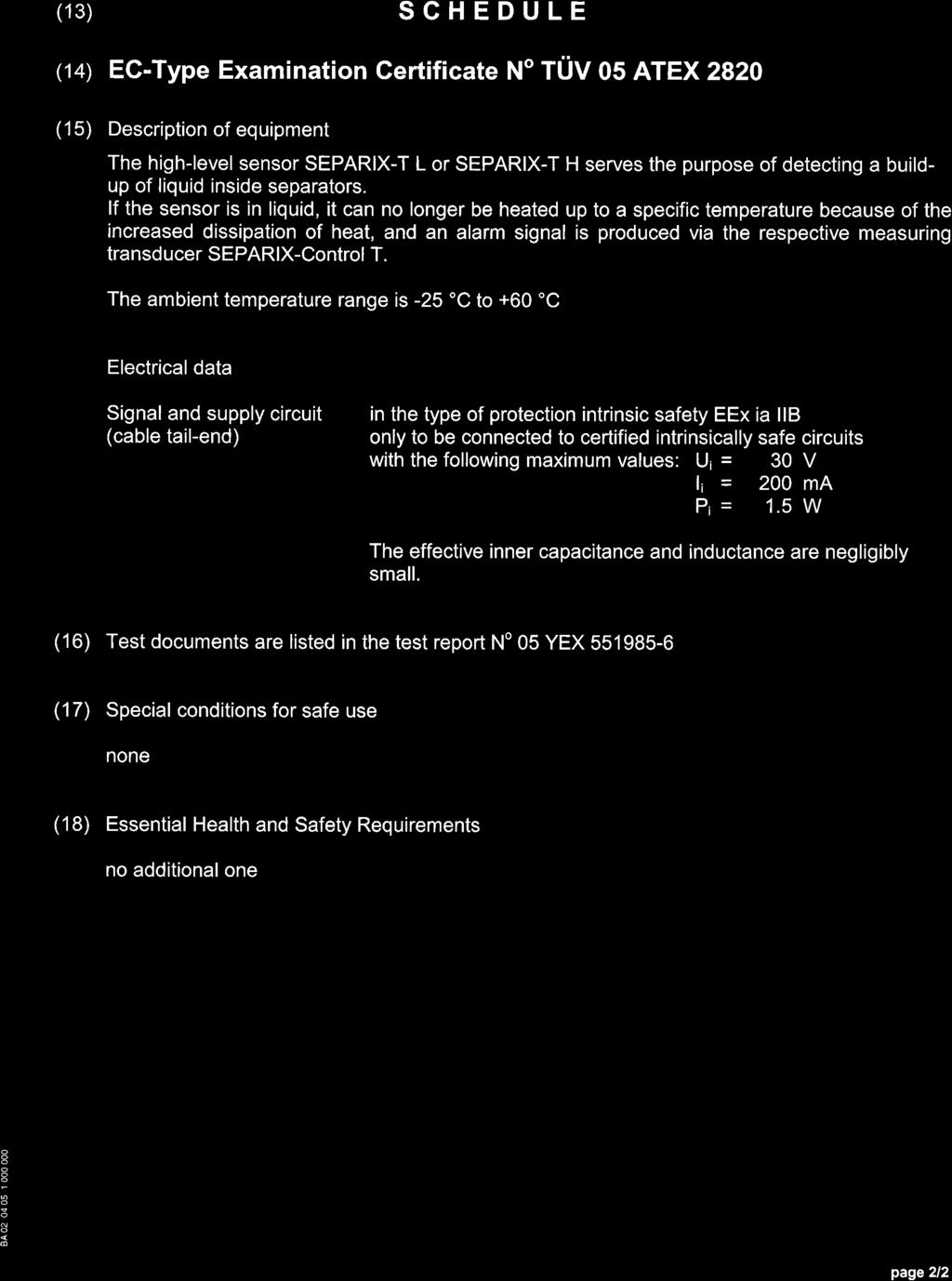
35 5 Technical data Temperature range: Ambient temperature C Media temperature C Inductance (outward acting) L i : Capacitance (outward acting) C i : Connection data: negligibly small negligibly small Labelling: EC type test certificate no. TÜV 05 ATEX 2820 The high-level sensor is only allowed to be connected to a circuit and with the following maximum values: No-load voltage U i : 30 V Short-circuit current I i : 200 ma Power P i : 1.5 W (in the entire range) In compliance with EC Directive 94/9: 0032 II 1 G EEx ia IIB T3 Page 2/2 FAFNIR GmbH Bahrenfelder Str. 19 D Hamburg Phone: +49 / (0) 40 / Fax: +49 / (0) 40 /
36
37
38
39 Instruction manual As of: Measuring transducer SEPARIX-Control CT Mode of operation The measuring transducer SEPARIX-Control CT is used for the power supply and analysis of the oil separator sensor SEPARIX-C.. and the high-level sensor SEPARIX-T... Alarms and malfunctions are signalled optically and acoustically by means of light-emitting diodes and a built-in buzzer. External alarm transmitters can be connected via potential-free changeover contacts, which are switched in the case of an alarm. The acoustic alarm can be acknowledged using the Alarm button. The optical alarm remains on until the cause of the alarm has been eliminated. An internal switch can be used for an optional setting to determine whether or not external alarm transmitters can be reset at the potential-free changeover contacts. Additional internal setting options are the automatic alarm repeating function after 24 hours, changeover contact switched in the alarm or normal state, and whether the alarm is to be activated for the detection of liquid or air. The function test for the internal and external alarm functions can be carried out using the Test button. Installation Connecting the auxiliary power, the oil separator sensor, the high-level sensor and an optional, external alarm transmitter must be carried out according to the connection diagram. The maximum values for the operating parameters mentioned on the wiring diagram must be observed. Wiring work may only be performed with the equipment in de-energized condition. The special VDE regulations and the local installation regulations must be observed. Operating instructions Before being put into service, all devices must be checked with respect to correct connection and proper operation. The electrical power supply, including the supply of the downstream devices, must be checked. The general operating instructions for the devices being used must be observed. The measuring transducer is maintenance-free. Page 1/2 FAFNIR GmbH Bahrenfelder Str. 19 D Hamburg Phone: +49 / (40) 40 / Fax: +49 / (40) 40 /
40 Technical data Auxiliary power Sensor circuits c SEPARIX-C.. Voltage Current Power Internal resistance Inductance (outward acting) Capacitance (outward acting) 230 V; Hz; ± 10 %; 8 VA U V I ma P mw R i 673 Ω L i negligible C i 1 nf IIC IIB Outer inductance L O 80 mh 300 mh Outer capacitance C O 0.68 µf 4.28 µf SEPARIX-T.. Voltage Current Power Internal resistance Inductance (outward acting) Capacitance (outward acting) U V I A P W R i Ω L i negligible C i 0.3 nf IIC IIB Maximum outer inductance L O 440 µh 100 µh 5 mh 1 mh Maximum outer capacitance C O 230 nf 310 nf 760 nf 1.6 µf Output circuits potential-free changeover contact Alternating voltage: U eff 250 V; I eff 5 A; P eff 500 VA; cos ϕ 0.7 Direct voltage U 250 V; I 0.25 A; P 50 W Ambient temperature 0 40 C Labelling: EC type test certificate no.: TÜV 05 ATEX 2819 In compliance with EC Directive 94/9: 0032 II (1) G [EEx ia] IIC / IIB Page 2/2 FAFNIR GmbH Bahrenfelder Str. 19 D Hamburg Phone: +49 / (40) 40 / Fax: +49 / (40) 40 /
41 Blank Page
42 Blank Page
43
44 FAFNIR GmbH Schnackenburgallee 149 c Hamburg, Germany Tel.: +49 / 40 / Fax: +49 / 40 / info@fafnir.com Web:
Manual Isolating Barrier D461R1 (Revision 01)
") D461R1 Manual Isolating Barrier D461R1 (Revision 01) Product Manual Original Instructions valid for models D461R1.11 with 1x signal input into 1x isolated signal output D461R1.12 with 1x signal input into
D461R1 Manual Isolating Barrier D461R1 (Revision 01) Product Manual Original Instructions valid for models D461R1.11 with 1x signal input into 1x isolated signal output D461R1.12 with 1x signal input into
OilSET Installation and Operating Instructions. Oil Separator Alarm Device with SET/DM3AL sensor
 Labkotec UK Ltd Adminicle House 1 Lumb Lane Audenshaw Manchester M34 5WH GREAT BRITAIN Tel: 0844 3350 477 Fax: 0161 4281 179 E-mail: info@labkotec.co.uk 10.8.2012 Internet: www.labkotec.co.uk 1/13 OilSET-1000
MANUAL Oil Level Sensor
 PROCESS AUTOMATION MANUAL Oil Level Sensor KVF-104-PF ISO9001 0102 With regard to the supply of products, the current issue of the following document is applicable: The General Terms of Delivery for Products
OilSET-1000 (12 VDC)
") Labkotec Oy Myllyhaantie 6 FI-33960 PIRKKALA FINLAND Tel: +358 29 006 260 Fax: +358 29 006 1260 Internet: www.labkotec.fi 20.03.2009 1/11 OilSET-1000 (12 VDC) Oil Separator Alarm Device Copyright 2009
Labkotec Oy Myllyhaantie 6 FI-33960 PIRKKALA FINLAND Tel: +358 29 006 260 Fax: +358 29 006 1260 Internet: www.labkotec.fi 20.03.2009 1/11 OilSET-1000 (12 VDC) Oil Separator Alarm Device Copyright 2009
SET-2000 Hi Level/Oil
 Labkotec Oy Labkotie 1 FI-36240 KANGASALA FINLAND Tel: + 358 29 006 260 Fax: + 358 29 006 1260 13.03.2008 Internet: www.labkotec.fi Alarm Device for Oil Separators Copyright 2008 Labkotec Oy We reserve
SET Installation and Operating Instructions. Level switch for one sensor
 Labkotec Oy Myllyhaantie 6 FI-33960 PIRKKALA FINLAND Tel.: +358 29 006 260 Fax: +358 29 006 1260 7.11.2013 Internet: www.labkotec.fi 1/14 SET-1000 Level switch for one sensor Copyright 2013 Labkotec Oy
SET-2000 Oil/Sludge. Alarm Device for Oil Separators. Installation and Operating Instructions
 SET-000 Oil/Sludge Alarm Device for Oil Separators Copyright 007 Labkotec Oy We reserve the right for changes without notice TABLE OF CONTENTS GENERAL... INSTALLATION... 4. SET-000 Oil/Sludge Control Unit...
OilSET Installation and Operating Instructions. Oil Separator Alarm Device
 Labkotec Oy Myllyhaantie 6 FI-33960 PIRKKALA FINLAND Tel: +358 29 006 260 Fax: +358 29 006 1260 18.11.2010 Internet: www.labkotec.fi 1/10 OilSET-1000 Oil Separator Alarm Device Copyright 2010 Labkotec
SET-2000 Oil/Sludge 12 VDC
 Labkotec Oy Myllyhaantie 6 FI-33960 PIRKKALA FINLAND Tel: + 358 29 006 260 Fax: + 358 29 006 1260 12.2.2015 Internet: www.labkotec.fi 1/14 SET-2000 Oil/Sludge 12 VDC Alarm Device for Oil Separators with
Manual Isolating Barrier D461 (Revision 05)
") D461 Manual Isolating Barrier D461 (Revision 05) Product Manual Original Instructions valid for models D461.11 with 1x signal input into 1x isolated signal output D461.12 with 1x signal input into 2x isolated
D461 Manual Isolating Barrier D461 (Revision 05) Product Manual Original Instructions valid for models D461.11 with 1x signal input into 1x isolated signal output D461.12 with 1x signal input into 2x isolated
MANUAL Overflow sensor NVF-104/34-PF
 PROCESS AUTOMATION MANUAL Overflow sensor NVF-104/34-PF ISO9001 0102 Overflow sensor NVF-104/34-PF With regard to the supply of products, the current issue of the following document is applicable: The
OPTIBAR P 1010/2010 C Supplementary instructions
 OPTIBAR P 1010/2010 C Supplementary instructions Pressure transmitter Equipment category II 1G / Ga, II 1D / Da in protection type intrinsic safety Exi KROHNE CONTENTS OPTIBAR P 1010/2010 C 1 Safety instructions
Inductive slot sensor
 0102 Model Number Features 2 mm slot width Technical Data specifications Switching function Normally closed (NC) Output type NAMUR Slot width 2 mm Depth of immersion (lateral) 5... 7 mm, typ. 6 mm Output
SITRANS T. SITRANS T Explosion protected temperature sensor. General information. Marking of the degree of protection. Range of uses.
 General information 1 Marking of the degree of protection 2 SITRANS T SITRANS T Explosion protected temperature sensor Operating Instructions Range of uses 3 Installation 4 Assembly and disassembly 5 Commissioning
INSTRUCTION MANUAL IS-mB1 Minialite Intrinsically Safe Round LED Beacon
 INSTRUCTION MANUAL Minialite Intrinsically Safe Round LED This instruction sheet describes installations which conform to EN60079:Part14:2008 Electrical Installation in Hazardous Areas. When designing
4) Intrinsic Safety Certification
 Intrinsic Safety Certification") INSTRUCTION MANUAL Minialert Intrinsically Safe Round Combined Unit Section Volume Control Tone Generator S2 S3 Tone Selection Switches Fig 1 Simplified block diagram The combined unit is CE marked for
INSTRUCTION MANUAL Minialert Intrinsically Safe Round Combined Unit Section Volume Control Tone Generator S2 S3 Tone Selection Switches Fig 1 Simplified block diagram The combined unit is CE marked for
OSA 3. Level alarm for oil separator. Afriso Ema AB. Kilvägen 2 SE Arlöv Sweden T +46-(0) F +46-(0)
 F +46-(0)") Level alarm for oil separator CONTENTS: Functional description... 2 Component parts... 3 Spare parts... 5 Safety regulations... 6 Checklist... 7 Installation... 8 Commissioning... 11 Operation... 14 Maintenance...
Level alarm for oil separator CONTENTS: Functional description... 2 Component parts... 3 Spare parts... 5 Safety regulations... 6 Checklist... 7 Installation... 8 Commissioning... 11 Operation... 14 Maintenance...
AND INSTALLATION MANUAL
 Labkotec Oy Myllyhaantie 6 FI-33960 PIRKKALA FINLAND Tel. +358 29 006 260 Fax +358 29 006 1260 Internet: www.labkotec.fi 10.10.2013 SET/DM3AL Level sensor OPERATION AND INSTALLATION MANUAL 1(5) SYMBOLS
Battery Powered Separator Alarm Type Standalone Unit. Installation, Operation & Maintenance
 Battery Powered Separator Alarm Type 17200 Standalone Unit Installation, Operation & Maintenance Battery Powered Separator Alarm Type 17200 Contents Declaration of Conformity 3 IMPORTANT 3 General Description
Sensor module. Operating instructions. Sensor module, Type 17-51P2-... Document No P2-7D0001 Version: 17 May 2011/Rev. 0
 Sensor module Operating instructions Sensor module, Document No. 11-51P2-7D0001 Version: 17 May 2011/Rev. 0 Operating Instructions Sensor-Module Type: 17-51P2-. Document no.: 11-51P2-7D0001 Version: 17.
Alarm system For oil-water separator
 INSTRUCTIONS MANUAL Alarm system For oil-water separator Safety precautions Fitting, wiring, initial start-up and maintenance operations must be done by trained technicians. All European and local rules
Technical Data. General specifications Switching element function DC Dual NC Rated operating distance s n 3 mm
 0102 Model Number Features Direct mounting on standard actuators EC-Type Examination Certificate TÜV99 ATEX 1479X Accessories BT32 BT32XS BT32XAS BT33 BT34 V1-G-N4-5M-PUR Female cordset, M12, 4-pin, NAMUR,
Operating Manual MS220DA
 ZIEHL industrie elektronik GmbH + Co KG Daimlerstraße 13, D 74523 Schwäbisch Hall + 49 791 504-0, info@ziehl.de, www.ziehl.de Temperature Relays and MINIKA Mains Monitoring Digital Panel Meters MINIPAN
Operating Manual MS220KA and MSR220KA
 Temperature Relays and MINIKA, Mains Monitoring, Digital Panel meters MINIPAN, Switching Relays and Controls Operating Manual MS220KA and MSR220KA ZIEHL industrie elektronik GmbH + Co KG Daimlerstraße
INSTRUCTION MANUAL (ATEX)
") INSTRUCTION MANUAL (ATEX) ISmA1M Minialarm Intrinsically Safe Round ISmA1M Volume Control Tone Generator S3 Tone Selection Switches Fig 1 Simplified block diagram The ISmA1M sounder is CE marked for compliance
INSTRUCTION MANUAL (ATEX) ISmA1M Minialarm Intrinsically Safe Round ISmA1M Volume Control Tone Generator S3 Tone Selection Switches Fig 1 Simplified block diagram The ISmA1M sounder is CE marked for compliance
Operating Manual MS220Vi and MSR220Vi
 ZIEHL industrie elektronik GmbH + Co KG Daimlerstraße 13, D 74523 Schwäbisch Hall + 49 791 504-0, info@ziehl.de, www.ziehl.de Temperature Relays and MINIKA Mains Monitoring Digital Panelmeters MINIPAN
Technical Data. General specifications. Rated operating distance s n 5 mm
 0102 Model Number Features 5 mm non-flush Usable up to SIL 2 acc. to IEC 61508 Technical Data specifications Switching function Normally closed (NC) Output type NAMUR Rated operating distance s n 5 mm
Installation and Operating Instruction
 Installation and Operating Instruction Automatic Fire Detectors Series 900 Ex (i) 9893 0.00 GB Technical changes reserved! 0 Installation and Operating Instruction Automatic Fire Detectors Series 900 Ex
VISY-X. Technical Documentation. VISY-SoftView V 1.7 User Guide for VISY-Command GUI and VISY-View Touch. Edition: Version: 6 Art.
 Technical Documentation VISY-X VISY-SoftView V 1.7 User Guide for VISY-Command GUI and VISY-View Touch Edition: 2015-04 Version: 6 Art. No: 350026 FAFNIR GmbH Bahrenfelder Str. 19 22765 Hamburg, Germany
Technical Data. Dimensions
 0102 Model Number Features 8 mm non-flush Stainless steel housing Usable up to SIL2 acc. to IEC 61508 Technical Data specifications Switching element function NAMUR, NC Rated operating distance s n 8 mm
LS 300 LS 500. Technical Documentation. Level detector. Measuring transducer. Edition: Version: 7 Art. No.:
 Technical Documentation LS 300 Level detector LS 500 Measuring transducer Edition: 2018-10 Version: 7 Art. No.: 207057 FAFNIR GmbH Schnackenburgallee 149 c 22525 Hamburg Tel: +49 /40 / 39 82 07-0 Fax:
Instruction Manual. Alarm Unit For Low Gas Level # Read manual before use! Observe all safety information! Keep manual for future use!
 Mess-, Regel- und Überwachungsgeräte für Haustechnik, Industrie und Umweltschutz Lindenstraße 20 74363 Güglingen Telefon +49 7135-102-0 Service +49 7135-102-211 Telefax +49 7135-102-147 info@afriso.de
Technical Data. Dimensions
 0102 Model Number Features 5 mm flush Usable up to SIL2 acc. to IEC 61508 Accessories EXG-18 Quick mounting bracket with dead stop BF 18 Mounting flange, 18 mm Technical Data specifications Switching element
Additional Operating Instructions SITRANS F. Vortex flowmeters. SITRANS FX330 Ex-d.
 Additional Operating Instructions SITRANS F Vortex flowmeters Ex-d Edition 09/208 CONTENTS Safety instructions 3. General notes... 3.2 EU conformity... 3.3 Approval according to the IECEx scheme... 3.4
OilMatic Pro / 230 V AC
 Instructions manual OilMatic Pro / 230 V AC Alarm system for oil-water separators OilMatic Pro 22-01-2017 Manufacturer: Bamo 1 Description...3 2 Mounting and start-up...4 3 Wiring...5 4 Startup - tests...7
OPTIWAVE X500 Supplementary Instructions
 OPTIWAVE X500 Supplementary Instructions OPTIWAVE 3500 C OPTIWAVE 6500 C OPTIWAVE 7500 C Supplementary Instructions for ATEX applications KROHNE CONTENTS OPTIWAVE X500 1 General safety information 4 1.1
Technical Data. General specifications Switching element function Rated operating distance s n 5 mm
 0102 Model Number Features 5 mm non-flush Usable up to SIL2 acc. to IEC 61508 Technical Data specifications Switching element function NAMUR, NC Rated operating distance s n 5 mm Installation non-flush
EU DECLARATION OF CONFORMITY
 The Low Voltage Directive (LVD) 2014/35/EU and Electromagnetic Compatibility (EMC) Directive 2014/30/EU. Capacitive level sensor DLS 27N(T) Capacitive level sensor type DLS 27N(T) is designed to bistable
PEPPERL+FUCHS GmbH
 Comfort series 1.5 mm embeddable M8x1 4 25 16 13 LED Switching element function NAMUR NC Rated operating distance s n 1,5 mm Installation embeddable Assured operating distance s a 0... 1,215 mm Reduction
Connection. e. g. Pt100. reference limit. yellow Output I. Composition
 Trip amplifiers for Pt1, Ni1 KFD2GREx1 Connection e. g. Pt1 Input EEx ia IIC 1+ 2 3 Hazardous area 1channel Input EEx ia IIC 2 switching points operate on 2 output relays High/low alarm can be selected
Technical Data. General specifications Switching element function Rated operating distance s n 5 mm
 0102 Model Number Features 5 mm flush Usable up to SIL 3 acc. to IEC 61508 Application Danger! In safety-related applications the sensor must be operated with a qualified fail safe interface from Pepperl+Fuchs,
RADAR LEVEL GAUGE SPECIAL SAFETY INSTRUCTION
 Special Safety Instruction en RADAR LEVEL GAUGE SPECIAL SAFETY INSTRUCTION Contents TankRadar Pro European ATEX Directive Information............................... 2 ATEX marking and Ex Certification
OPTIBAR DP 7060 Supplementary Instructions
 OPTIBAR DP 7060 Supplementary Instructions Differential pressure transmitter Category ATEX II 1/2G, 2G Ex db ia IIC T6...T1 Ga/Gb, Gb IECEx Ex db ia IIC T6...T1 Ga/Gb, Gb Housing Aluminium: Single chamber,
INSTRUCTION MANUAL (ATEX / IECEx)
") INSTRUCTION MANUAL (ATEX / IECEx) BExS110D and BExS110D-R Sounder For use in Flammable Gas and Dust Atmospheres BExS110D BExS110D-R 1) Warnings DO NOT OPEN WHEN AN EXPLOSIVE ATMOSPHERE IS PRESENT DO NOT
INSTRUCTION MANUAL (ATEX / IECEx) BExS110D and BExS110D-R Sounder For use in Flammable Gas and Dust Atmospheres BExS110D BExS110D-R 1) Warnings DO NOT OPEN WHEN AN EXPLOSIVE ATMOSPHERE IS PRESENT DO NOT
Additional Operating Instructions SITRANS F. Vortex flowmeters. SITRANS FX330 Ex-i.
 Additional Operating Instructions SITRANS F Vortex flowmeters Ex-i Edition 09/2018 CONTENTS 1 Safety instructions 3 1.1 General notes... 3 1.2 EU conformity... 3 1.3 Approval according to the IECEx scheme...
Supplementary Installation and Operating Instructions. Category II2G
 Supplementary Installation and Operating Instructions Flap-type Flow Meter Category II2G 2 Contents 1. General safety directions...3 2. Main safety-relevant characteristics...4 2.1. Category / Zone...4
Technical Data. General specifications Switching element function Rated operating distance s n 4 mm
 0102 Model Number Features 4 mm non-flush Accessories BF 12 Mounting flange, 12 mm Technical Data specifications Switching element function NAMUR, NO Rated operating distance s n 4 mm Installation non-flush
Alarm Switchgear AS1-M
 Installation, Operating and Maintenance Instructions 1/7 Installation, Operating, and Maintenance Manual for Alarm Switchgear AS1-M These installation, operating and maintenance manual must be handed to
Physikalisch-Technische Bundesanstalt
 (1) EC-TYPE-EXAMINATION CERTIFICATE (Translation) (2) Equipment and Protective Systems intended for Use in Potentially Explosive Atmospheres Directive 94/9/EG (3) EC-type-examination Certificate Number:
MAINS KLARGESTER SEPARATOR ALARM INSTALLATION & OPERATIONS MANUAL
 MAINS KLARGESTER SEPARATOR ALARM INSTALLATION & OPERATIONS MANUAL Contents IMPORTANT... 3 General Description... 4 General Operation... 4 Changing Factory Settings... 4 Alarm Type... 4 Check Interval...
Capacitive leakage detectors of the Leckmaster range for installation in normally dry rooms
 Capacitive leakage detectors of the Leckmaster range for installation in normally dry rooms Jola Spezialschalter GmbH & Co. KG Klostergartenstr. 11 67466 Lambrecht (Germany) Tel. +49 6325 188-01 Fax +49
DB5 Intrinsically Safe Sounder Type DB-5
 Operating Instructions RTK Instruments Limited DB5 Intrinsically Safe Sounder Type DB-5 Description The DB5 Sounder is a strong, lightweight warning sounder, CENELEC certified to Ex II 1G EExia IIC T4
DUR 40Ex Intrinsically Safe SMOKE DETECTOR
 DUR 40Ex Intrinsically Safe SMOKE DETECTOR Installation and Maintenance Manual IK E317 001GB IB Issue 2 IK E317 001GB The Universal Optical Smoke Detector DUR 40Ex covered by the present manual, complies
14300 MAINS SEPARATOR ALARM MANUAL
 Conder Environmental Solutions 14300 MAINS SEPARATOR ALARM MANUAL Separator and Alarm provided by: Alarm Installation, Commissioning & Servicing Support Please contact: www.envirotank.com.au www.envirotank.co.nz
Operating Manual MS220VA and MSR220VA
 ZIEHL industrie elektronik GmbH + Co KG Daimlerstr.13, 74523 Schwäbisch Hall, Germany + 49 791 504-0, info@ziehl.de, www.ziehl.de Temperature Relays and MINIKA Mains Monitoring Digital Panelmeters MINIPAN
Instruction Manual. Electronic gas and smoke detector GRM
 Mess-, Regel- und Überwachungsgeräte für Haustechnik, Industrie und Umweltschutz Lindenstraße 20 DE-74363 Güglingen Telefon +49(0)7135-102-0 Service +49(0)7135-102-211 Telefax +49(0)7135-102-147 E-Mail
VERSAFLOW VORTEX Supplementary instructions
 VERSAFLOW VORTEX Supplementary instructions Vortex flowmeter Equipment category II 2G CONTENTS VERSAFLOW VORTEX 1 Safety instructions 3 1.1 General notes... 3 1.2 EC conformity... 3 1.3 Approval according
Operating instructions
 MA00929301 09/2015 Operating instructions ED10429002 ESYLUX GmbH An der Strusbek 40 22926 Ahrensburg Germany info@esylux.com www.esylux.com 1 Table of contents 1 Using the manual 8 2 Safety instructions
PROZESSAUTOMATION. Manual SEGMENT PROTECTOR R-SP-!12. Zone 1 Zone 2 / Div 2 FNICO
 PROZESSAUTOMATION Manual SEGMENT PROTECTOR R-SP-!12 FieldConnex TM Segment Protectors with overloaod protection and short-circuit current limitation for the connection of 12 field devices Zone 1 Zone 2
Rosemount 3490 Series 4 20 ma + HART Compatible Controller
 00825-0200-4841, Rev AB Rosemount 3490 Series 4 20 ma + HART Compatible Controller Failure to follow safe installation guidelines could result in death or serious injury The Rosemount 3490 Series Control
Additional Operating Instructions SITRANS F. Vortex flowmeters. SITRANS FX330 Ex-nA.
 Additional Operating Instructions SITRANS F Vortex flowmeters Ex-nA Edition 08/207 CONTENTS Safety instructions 3. General notes... 3.2 EU conformity... 3.3 Approval according to the IECEx scheme... 3.4
SolarSET GSM SolarSET GSM with a Beacon
 Labkotec Oy Myllyhaantie 6 FI-33960 Pirkkala FINLAND Tel. +358 29 006 260 Fax +358 29 006 1260 13.08.2009 Internet: www.labkotec.fi SolarSET GSM SolarSET GSM with a Beacon Solar Powered Oil Separator Alarm
2CKA001473B System Manual Busch-Infoline. Handicapped toilet signal set 1510 UC
 2CKA001473B9007 19.05.2017 System Manual Busch-Infoline Handicapped toilet signal set 1510 UC-... -101 Table of contents Table of contents 1 Notes on the instruction manual... 3 2 Safety... 4 2.1 Information
INSTRUCTION MANUAL (ATEX/IECEx/SIL2) BExBG05D-SIL Flameproof Xenon SIL 2 Beacons For use in Flammable Gas and Dust Atmospheres
 BExBG05D-SIL Flameproof Xenon SIL 2 Beacons For use in Flammable Gas and Dust Atmospheres") INSTRUCTION MANUAL (ATEX/IECEx/SIL2) BExBG05D-SIL Flameproof Xenon SIL 2 Beacons For use in Flammable Gas and Dust Atmospheres 1) Introduction The BExBG05D-SIL is a flameproof beacon which is certified
INSTRUCTION MANUAL (ATEX/IECEx/SIL2) BExBG05D-SIL Flameproof Xenon SIL 2 Beacons For use in Flammable Gas and Dust Atmospheres 1) Introduction The BExBG05D-SIL is a flameproof beacon which is certified
ATEX Installation Instructions for Micro Motion F-Series Sensors with Certificate DMT 01 ATEX E 158 X
 Installation Instructions P/N MMI-20010174, Rev. A June 2007 ATEX Installation Instructions for Micro Motion F-Series Sensors with Certificate DMT 01 ATEX E 158 X For ATEX-approved sensor installations
Intrinsically Safe Solutions
 Intrinsically Safe Solutions INSTALLATION MANUAL 04/12/14 Rev D DOC-01-029 Documentation Feedback Your feedback helps us keep our documentation up to date and accurate. If you have any comments or suggestions
Annubar Flowmeter Series
 Reference Manual Appendix B Approvals Annubar Flowmeter Series Hazardous Locations Installations.................. page B-1 Rosemount 3051SFA Product Certifications.......... page B-1 Rosemount 3095MFA
Multipoint temperature sensor
 Multipoint temperature sensor ATEX e / t for use in areas with an explosion hazard Persons concerned: Experienced professional electricians as per EU Directive 1999/92/EC and trained personnel B 903530.0.0
Operating Instructions Edition 02/2007
 Operating Instructions Edition 02/2007 Temperature Transmitter 7NG3214 with PROFIBUS PA 7NG3215 with FOUNDATION Fieldbus sitrans Introduction 1 General safety notes 2 SITRANS T Temperature transmitter
INSTRUCTION & SERVICE MANUAL
 INSTRUCTION & SERVICE MANUAL D2xC1 ALARM HORN AND STROBE For Use In Hazardous Locations 3) Ratings and Markings 3.1 ATEX / IECEx certification The D2xC1 Alarm Horn and Strobe complies with the following
Instruction manual. Digital Radar Motion Detector with Infrared Remote Control MWD BF. FEIG ELECTRONIC GmbH Lange Straße Weilburg/Lahn
 Instruction manual Digital Radar Motion Detector with Infrared Remote Control MWD BF FEIG ELECTRIC GmbH Lange Straße 4 35781 Weilburg/Lahn 22.08.02 MWD BF Instruction manual General Copyright 2002 by FEIG
IECEx Certificate of Conformity
 Page 1 of 10 IECEx Certificate of Conformity INTERNATIONAL ELECTROTECHNICAL COMMISSION IEC Certification Scheme for Explosive Atmospheres for rules and details of the IECEx Scheme visit www.iecex.com Certificate
Safety instructions VEGADIF DF65.GX*****H/Z/P/F***** IECEx BVS
 Safety instructions VEGADIF DF65.GX*****H/Z/P/F***** IECEx BVS 10.0008 Ex td A20, A20/21, A20/22, A21 IP66 T 0044 37675 Contents 1 Area of applicability 3 2 General information 3 2.1 Zone 20 instruments
Translation of the assembly instructions with operating instructions and technical appendix
 BA Ex-SBU Switch box type SBU-x(1,2,3)x Translation of the assembly instructions with operating instructions and technical appendix In accordance with EU ATEX Directive 2014/32/EU In accordance with EU
ATEX GUIDE. A short introduction to ATEX Terminology. Equipment for use in flammable atmospheres. Directive 94/9/EC
 Quick Introduction to TÛV Denmark TÜV Denmark - is a part of the TÜV NORD Group a global Organisation f Certification and Inspection of: Quality Management Systems, Products, Processes and Qualification
E2S Datasheet v10a. The IS-mA1 is suitable for all intrinsically safe signalling applications including fire, security and process control.
 E2S Datasheet 1.2.1 v10a ISmA1 ISminialarm The ISmA1 is a compact, 100dB(A) alarm sounder. Approvals include ATEX, IECEx and GOSTR for Zone 0 applications and FM approval for Class I Division 1 and Class
L+T GASETECHNIK. Klöpper-Waldmann GmbH & Co. K G. Alarm unit LSG4
 Areas of application The LSG4 alarm unit is used for monitoring industrial systems, e.g. in the following areas: Alarm and hazard stati in production e.g. for monitoring temperature and pressure in reactors
FSW300 Series Flow Switch
 . FSW300 Series Flow Switch - 2 - Series FSW300 Series FSW300 Table of contents page 0 About this operating manual... 4 1 Device description... 5 1.1 Intended use... 5 1.1.1 Reed contact - Switching of
Dual certification! Air handling units for potentially explosive atmospheres
 Dual certification! Air handling units for potentially explosive atmospheres X-CUBE Ex A certified safety product The air handling unit with dual ATEX certification ATEX directive 2014/34/EU applies to
Operating Instructions Edition 11/2005. Process monitoring Ex-barrier for Diagnostics Unit SITRANS DA400 7MJ2010-1AA. sitrans
 Operating Instructions Edition 11/2005 Process monitoring Ex-barrier for Diagnostics Unit SITRANS DA400 7MJ2010-1AA sitrans Introduction 1 General safety instructions 2 SITRANS Process monitoring Ex-barrier
M LLET. Silo pressure detector. Füllstandtechnik. Operating instructions. 1. Description. 1.5 Dimensions. 1.1 Intended use. 1.
 Operating instructions 1. Description 1.1 Intended use The pressure detector controls as limit switch the overpressure in silos and vessels. 1.5 Dimensions 1.2 Function If the pressure reaches the switching
PESO. Temperature sensors with cables Thermocouples and RTD temperature probes ATEX I, e, t For use in areas with an explosion hazard
 Temperature sensors with cables Thermocouples and RTD temperature probes ATEX I, e, t For use in areas with an explosion hazard Persons concerned: Experienced professional electricians as per EU Directive
Circulation heaters for ATEX/IECEx hazardous areas or in non-atex version
 for ATEX/IECEx hazardous areas or in non-atex version * Non contractual picture Warning It is imperative to read these instructions carefully before installing or maintaining the equipment. MI500EN 09/2017
Operating Instructions for Limit switch Model: NBK-R NBK-RM NBK-RT NBK-RA
 Operating Instructions for Limit switch Model: NBK-R NBK-RM NBK-RT NBK-RA 1. Contents 1. Contents... 2 2. Note... 3 3. Instrument Inspection... 3 4. Regulation Use... 3 4.1 Electrical limit switch... 4
Technical Data. General specifications Switching element function Rated operating distance s n 8 mm
 0102 Model Number Features 8 mm non-flush Usable up to SIL 3 acc. to IEC 61508 Application Danger! In safety-related applications the sensor must be operated with a qualified fail safe interface from Pepperl+Fuchs,
A6 Safety Monitoring Device
 A6 Safety Monitoring Device PL 0 10 2.2 Manual Publisher NEW LIFT Steuerungsbau GmbH Lochhamer Schlag 8 D- 82166 Gräfelfing Germany Tel.: +49 (0) 89 / 8 98 66-0 Fax: +49 (0) 89 / 8 98 66-3 00 Doc. No.
DICTATOR Hold-Open Systems for Hazardous Areas
 DICTATOR for Hazardous Areas Products to be used in hazardous areas obviously have to meet special demands. The European ATEX directives (first the EN 94/9/EG and then the directive 2014/34/ EU) brought
Air Sensor. SAC Ex FCS Ex. Manual ATEX. AQ M-Tech AB
 Air Sensor SAC Ex FCS Ex Manual AQ M-Tech AB ATEX Air Sensor SAC Ex FCS Ex ATEX Certified AQ M-Tech AB Manual version 2.2 February 2017 2 Air Sensor Manual for SAC Ex and FCS Ex Table of contents 1. Manufacturer
Snifter ATEX22 VERSION. User Manual. Distributor
 Snifter ATEX22 VERSION User Manual Distributor Version 1.4 09/09/2009 Table of Contents 1. INTRODUCTION... 3 1.1. Safety... 3 1.2. Product overview... 4 1.3. How does it work?... 4 2. INSTALLATION... 5
Operating Instructions
 Mess-, Regel- und Überwachungsgeräte für Haustechnik, Industrie und Umweltschutz Lindenstraße 20 DE-74363 Güglingen Telefon: +49(0)7135-102-0 Service: +49(0)7135-102-211 Telefax: +49(0)7135-102-147 E-Mail:
Installationsmanual GWSL1100/2100, GWML3100
 GRAIN-WATCH SYSTEM Installationsmanual Grain Watch Sensor Cables GWSL1100/2100, GWML3100 Table of contents 1 1 1 3. Safety certification and features 3.1. Certification label information 3.2. Safety approvals
Pressure sensors. Ex ia I / IIC T6 acc. to ATEX. Features. Description. Measuring ranges. Applications
 Force Pressure Temperature Switch Pressure sensors Ex ia I / IIC T6 acc. to ATEX with internal diaphragm with front flush diaphragm Accuracy: 0,25% and 0,5 % Standard output: 4...20 ma; 2-wire system Description
Solar Separator Alarm Type Installation, Operation & Maintenance
 Solar Separator Alarm Type 14007 Installation, Operation & Maintenance Solar Separator Alarm Type 14007 Contents Declaration of Conformity 3 Important 3 General Description 3 General Operation 3 Changing
KHA6-GT*-Ex1. Thermocouple trip amplifiers. Composition. Hazardous area. Safe area. Function. 230 V AC 1-channel. Input EEx ia IIC
 Thermocouple trip amplifiers KHA6GT*Ex1 23 V AC 1channel Input EEx ia IIC Cold junction compensation 2 switching points operate on 2 output relays High/low alarm can be selected for each switching point
User s Manual YTA610 and YTA710 NEPSI Certification
 User s Manual YTA60 and YTA70 NEPSI Certification [Option code: /NS, /NS5 and /NF] st Edition . INTRODUCTION Thank you for purchasing the YTA60 and YTA70 Temperature transmitters. This manual contains
OMC Ex interface unit. Manual. Version 1.2 August Author: Observator Instruments
 OMC-158-2 Ex interface unit Manual Version 1.2 August 2017 Author: Observator Instruments Revisions: 0.1 (October 2016) First issue 0.2 (December 2016) Prototype 0.3 (January 2017) Test release 1.0 (March
IECEx Certificate of Conformity
 INTERNATIONAL ELECTROTECHNICAL COMMISSION IEC Certification Scheme for Explosive Atmospheres for rules and details of the IECEx Scheme visit www.iecex.com Certificate No. : Status: Date of Issue: Applicant:
OPTISENS TUR 2000 Technical Datasheet
 OPTISENS TUR 2000 Technical Datasheet Sensor for turbidity measurement in water and wastewater Rugged design for harsh applications Integrated transmitter with direct 4...20 ma output Near infrared light
SITRANS Pressure transmitter SITRANS LH300 (7MF1575..) Transmitter for hydrostatic level Compact Operating Instructions
 Transmitter for hydrostatic level Compact Operating Instructions") SITRANS Pressure transmitter Compact Operating Instructions Legal information Warning notice system This manual contains notices you have to observe in order to ensure your personal safety, as well as
SITRANS Pressure transmitter Compact Operating Instructions Legal information Warning notice system This manual contains notices you have to observe in order to ensure your personal safety, as well as
BA334D Intrinsically safe Externally powered pulse input field mounting rate totaliser Issue 13
 TR Automatyka Sp. z o. o. Tel. (+48 022) 886 10 16 www.trautomatyka.pl ul. Lechicka 14 ; 02-156 Warszawa Fax. (+48 022) 846 50 37 biuro@trautomatyka.pl BA334D Intrinsically safe Externally powered pulse