INSTALLATION, OPERATING AND MAINTENANCE
|
|
|
- Eugenia Reynolds
- 5 years ago
- Views:
Transcription


1 INSTALLATION, OPERATING AND MAINTENANCE VERTICAL PACKAGED AIR CONDITIONER COMPACTAIR 8-85 kw COMPACTAIR ADV IOM- MIL157E /2018
2 Read this manual before installation, reparation o maintenance works. POINTS TO BEAR IN MIND 2 DATA PAGE FOR COMMISSIONING UNIT 3 1. GENERAL CHARACTERISTICS Product range General description Physical data Electrical data Operating limits Fan performances Refrigeration drawings Sound levels Dimensions - split units Dimensions - packaged units Air supply confi guration Options INSTALLATION Preliminary preparations Unit acceptance Unit location Ducts and sensor installation Installation clearances Drains Cooling connections Electrical connections Terminal connection COMMISSIONING AND OPERATION Preliminary checks Preliminary checks at startup CLIMATIC Configuration MAINTENANCE PREVENTIVE MAINTENANCE MAINTENANCE PLAN CORRECTIVE MAINTENANCE FAILURE DIAGNOSIS END OF LIFE CYCLE OF THE UNIT 43 Lennox have been providing environmental solutions since 1895, our COMPACTAIR ADVANCED range continues to meet the standards that have made LENNOX a household name. Flexible design solutions to meet your needs and uncompromising attention to detail. Engineered to last, simple to maintain and Quality that comes as standard. For information on local contacts at The manufacturing of these units is made under the requirements of the ISO 9001 and ISO All the information contained in this manual, including any drawing and technical descriptions provided by us, remain the property of Lennox and must not be used (except in the operation of this product), reproduced, issued to or made available to third parties without the prior written agreement of Lennox. LENNOX, in its commitment to preserve the environment, has an Environmental Management System based on ISO 14001, through which all environmental aspects generated during its activity are managed and continuously improved, taking into account the life cycle of the products we manufacture and market. For this reason, you: customer, user and / or maintainer of the equipment, are invited to join our commitment to conserve our environment, and follow the indications that we expose throughout this manual. 1
3 POINTS TO BEAR IN MIND DANGER AND WARNING SIGNS Abrasive surfaces Low temperatures High temperatures Risk of injury by moving objects Electrical voltage Risk of injury by rotating objects ELECTRICAL CONNECTIONS Make sure to switch off the power before installing, repairing or carrying out maintenance on the unit, in order to prevent serious electrical injury. Keep local and national legislation in mind when installing the unit. WARNING - REMEMEBER Switch off the general power switch of the air conditioning unit on the electrical panel of the location. The cleaning of filters does not require specialized personnel, for other types of interventions like electrical or mechanical advise the specialized technician. FILTER CLEANING Ensure to open the electrical disconnect switch to the network before accessing the unit for its installation, repair or maintenance to avoid possible deaths or injuries from electric shock. If the filter is too dirty, wash it in a container with water and neutral soap, drying it in the shade before inserting it back into the unit. Standard Guidelines to Lennox equipment: All technical data contained in these operating instructions, including the diagrams and technical description remains the property of Lennox and may not be used (except for the purpose of familiarizing the user with the equipment), reproduced, photocopied, transferred or transmitted to third parties without prior written authorization from Lennox. The data published in the operating instructions is based on the latest information available. We reserve the right to make modifi cations without notice. We reserve the right to modify our products without notice without obligation to modify previously supplied goods. These operating instructions contain useful and important information for the smooth operation and maintenance of your equipment. The instructions also include guidelines on how to avoid accidents and serious damage before commissioning the equipment and during its operation and how to ensure smooth and fault-free operation. Read the operating instructions carefully before starting the equipment, familiarize yourself with the equipment and handling of the installation and carefully follow the instructions. It is very important to be properly trained in handling the equipment. These operating instructions must be kept in a safe place near the equipment. Like most equipment, the unit requires regular maintenance. This section concerns maintenance and management personnel. If you have any queries or would like to receive further information on any aspect relating to your equipment, do not hesitate to contact us. 2
4 D ATA PAGE FOR UNIT COMMISSIONING UNIT: SERIAL Nr: CONTROL PANEL IDENTIFICATION CODE: INSTALLATION ADDRESS: INSTALLER: INSTALLER TEL: INSTALLER ADDRESS: DATE OF COMMISSIONING: CHECKS: SUPPLY VOLTAGE: RATED VOLTAGE OF THE UNIT: YES NO UNIT ON SHOCK ABSORBERS DRAINAGE WITH TRAP MAIN POWER SUPPLY CONNECTION CONTROL PANEL CONNECTION COMPRESSOR OIL LEVEL INDICATOR DATA INPUT: COOLING CYCLE HEATING CYCLE Air intake temperature to the outdoor coil: 1 ºC 2 ºC Air intake temperature to the outdoor coil: 1 ºC 2 ºC Air output temperature to the outdoor coil: 1 ºC 2 ºC Air output temperature to the outdoor coil: 1 ºC 2 ºC High pressure: circuit 1 circuit 2 High pressure: circuit 1 circuit 2 Low pressure: circuit 1 circuit 2 Low pressure: circuit 1 circuit 2 ELECTRIC POWER CONSUMPTION (Amps) Compressor 1 Compressor 2 Compressor 1 Compressor 2 Compressor 3 Compressor 3 Outdoor fan section 1 Outdoor fan section 1 Outdoor fan section 2 Outdoor fan section 2 Options installed: Comments: 3
5 1.- GENERAL CHARACTERISTICS PRODUCT RANGE. CA M H 025 S M 1 M Unit COMPACTAIR ADVANCED M: Package unit S: Outdoor unit I: Indoor unit H: Heat pump Approximate cooling capacity in kw S: One Circuit D: Two Circuits Type of refrigerant M: R-410A Number of revision T: 230V/1/50 M: 400V/3/50 UNIT HEAT PUMP. UNITS Cooling capacity (kw) Heating capacity (kw) V/Ph/50 Hz min nom max min nom max PACKAGE CAMH025SM1M 400 V 3 Ph 8,5 17,9 22,4 5,8 15,2 19,6 CAMH035SM1M 400 V 3 Ph 13,0 26,4 32,4 9,5 22,4 29,5 CAMH045SM1M 400 V 3 Ph 13,8 39,0 45,0 13,9 29,2 42,2 CAMH060DM1M 400 V 3 Ph 41,7 53,9 59,8 35,4 45,8 56,2 CAMH075DM1M 400 V 3 Ph 40,2 64,8 71,0 45,3 56,0 67,7 CAMH085DM1M 400 V 3 Ph 55,3 79,5 85,3 50,9 65,8 80,8 OUTDOOR UNIT INDOOR UNIT CASH025SM1M CAIH025SM1M 400 V 3 Ph 8,5 17,9 22,4 5,8 15,2 19,6 CASH035SM1M CAIH035SM1M 400 V 3 Ph 13,0 26,4 32,4 9,5 22,4 29,5 CASH045SM1M CAIH035SM1M 400 V 3 Ph 13,8 39,0 45,0 13,9 29,2 42,2 CASH060DM1M CAIH060SD1M 400 V 3 Ph 41,7 53,9 71,0 45,3 56,0 67,7 CASH075DM1M CAIH075DM1M 400 V 3 Ph 40,2 64,8 71,0 45,3 56,0 67,7 CASH085DM1M CAIH085DM1M 400 V 3 Ph 55,3 79,5 85,3 50,9 65,8 80,8 UNITS EER cold (Kw/Kw) COP heat (Kw/Kw) V/Ph/50 Hz min nom max min nom max PACKAGE CAMH025SM1M 400 V 3 Ph 3,92 3,06 2,81 4,32 3,42 2,42 CAMH035SM1M 400 V 3 Ph 4,41 2,86 2,46 4,35 3,03 2,28 CAMH045SM1M 400 V 3 Ph 2,49 2,75 2,25 4,24 2,96 2,24 CAMH060DM1M 400 V 3 Ph 6,61 2,78 2,51 3,06 2,99 2,56 CAMH075DM1M 400 V 3 Ph 3,23 2,66 2,51 2,69 2,77 2,48 CAMH085DM1M 400 V 3 Ph 4,97 2,69 2,41 3,00 2,79 2,48 OUTDOOR UNIT INDOOR UNIT CASH025SM1M CAIH025SM1M 400 V 3 Ph 3,92 3,06 2,81 4,32 3,42 2,42 CASH035SM1M CAIH035SM1M 400 V 3 Ph 4,41 2,86 2,46 4,35 3,03 2,28 CASH045SM1M CAIH035SM1M 400 V 3 Ph 2,49 2,75 2,25 4,24 2,96 2,24 CASH060DM1M CAIH060SD1M 400 V 3 Ph 6,61 2,78 2,51 3,06 2,99 2,56 CASH075DM1M CAIH075DM1M 400 V 3 Ph 3,23 2,66 2,51 2,69 2,77 2,48 CASH085DM1M CAIH085DM1M 400 V 3 Ph 4,97 2,69 2,41 3,00 2,79 2,48 Cooling: Indoor Tª: 27ºC DB / 19ºC WB. Outdoor Tª: 35ºC DB. Heating: Indoor Tª: 20ºC DB / 12ºC WB. Outdoor Tª: 7ºC DB / 6ºC WB. 4
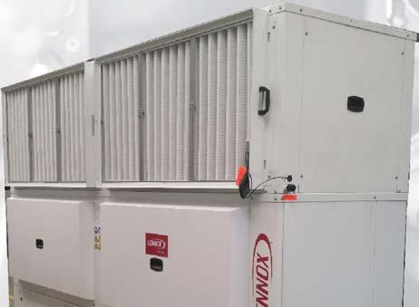
6 1.- GENERAL CHARACTERISTICS GENERAL DESCRIPTION. The vertical self-contained conditioners, Compactair Advanced range, in the heat pump version are air condensed units that have been designed for small commercial and residential installations. The units consist of two sections, an indoor section and an outdoor section, are units that by their design can be supplied in package and split version. They are designed for operation coupled to a network of air distribution ducts in indoor and outdoor sections. With the option of incorporating a wide range of accessories and options. The manufacturing of these units is made under the strict quality requirements of the standard ISO CASING. Galvanized and painted sheetmetal casing. The units incorporate metal supports attached to the base, for its correcthoisting. These supports allow to install the unit on the fl oor, providing great rigidity to the installation of the unit. The panels are easily interchangeable allowing several alternatives of impulsion and return air. The outdoor and indoor sections are insulated thermally and acoustically. In the indoor units, an insulation with aluminum mesh protection with M1 and F1 classifi cation is used, certifying that this material is self-extinguishing in case of fi re, avoiding the formation of fumes that could enter the premises to be conditioned. In the outdoor units, insulation with M1 classifi cation is used. GENERAL SWITCH. Located in the access panel to the electrical board and equipped with a mechanism which only allows the opening of the panel of the electrical board when the switch is OFF position. FANS. The fans of the indoor and outdoor sections are of EC Plug Fan type. The fans are regulated automatically to obtain a variable air volume in indoor and outdoor unit. COOLING CIRCUIT. Made with dehydrated copper tubes welded with pressure sockets with a shutter valve on the suction and unloading lines, in outdoor and indoor section. The unit incorporates a high-pressure minipresostat and high-pressure and lowpressure transducers. It incorporates dehydrator filter, expansion system with electronic valves, one in the package units and two in the split units. The units in heat pump incorporate suction accumulator to avoid the migration of liquid to the compressor, reversible valve for inversion cycle and unidirectional valves. The split units also include an oil separator. INDOOR- OUTDOOR UNIT INTERCONNECT CABLE. The connection between indoor and outdoor units, must be carried out using a shielded hose of 3x0.5mm 2. COMPRESSORS. All the models incorporate a Inverter compressor type Scroll with brushless motor (BLDC), which by means of an electronic system regulates the engine revolutions and through the frequency variation adapts to the needs of the installation and modulates the gasfl ow of the refrigerant in all moment. Two circuit units incorporate also tandem compressor, scroll type. The compressors are mounted on silentblocks. AIR FILTER. EXCHANGERS. Manufactured with copper tubes and corrugated or lourvered aluminum fins, designed to get high heat transfer. Their dimensions and design of the circuits have been specially studied to obtain the maximum performance of the exchangers, increasing the capacity of the unit and reducing the consumption. ELECTRICAL CIRCUIT. Designed according to standard EN With thermal protection magnets for compressors and fans. All compressor and fan motors incorporate internal thermal protectors. An electronic control governs the operation of the unit, manages the driver of the compressor, the fans EC Plug Fan and the electronic expansion valves. Washable air filter, self-extinguishing material in case of fi re with M1 classification, high fi ltering effi ciency, with G4 classification. With the possibility of extracting it from the lateral side. Option: High Efficiency Filter M5+F7. 5
7 1.- GENERAL CHARACTERISTICS GENERAL DESCRIPTION. OPTIONS. Fresh air: - Kit Freecooling. - Return fan module. Filtration: - High efficiency fi lter: M5+F7. Auxiliary Heat : - Electrical resistance mounted inside the standard, medium or high capacity unit. Security and electricity : - Air quality sensor (CO 2 ). - Smoke detector. - Analog dirty filter sensor. - Energy counting. - Three phases relay for unit electrical protection. Coils Treatment: - Anticorrosion protection condensor & evaporator coils. Refrigerant circuit: - Sevice valves. - Refrigerant precharged. Control and comunication: - Remote display DC for user. - Service display DS. - Multi Unit Display DM. - Remote probe in environment. - Modbus RS485 comunication interface. - LonWorks FTT10 comunication interface. - BACnet MSTP comunication interface. - Modbus/BACnet/Ethernet TCP/IP comunication interface. - Expansion board Others: - A1 Insulation air treatment unit. - Low noise: compressor acoustic insulation. DC DM Service Display DS 6
8 1.- GENERAL CHARACTERISTICS PHYSICAL DATA. SET Cooling capacity (*) Kw Heating capacity (**) Kw Nominal absorbed power (Cold) (*) Kw Nominal absorbed power (Heating) (**) Kw DIMENSIONS Height mm Width mm Depth mm NET WEIGHT Kg OUTDOOR UNIT COMPRESSOR Nº / type FAN Nominal airfl ow m 3 /h Available preassure Pa DIMENSIONS Height mm Width mm Depth mm NET WEIGHT Kg PIPING CONNECTIONS LIquid inches Gas inches INDOOR UNIT FAN Nº / type Airfl ow (Min / Max) m 3 /h Available preassure (***) Pa DIMENSIONS Height mm Width mm Depth mm NET WEIGHT Kg PIPING CONNECTIONS Liquid inches Gas inches NET WEIGHT OF OPTIONALS Free-cooling Kg Electrical Heater Kg Filter M5+F7 Kg Return fan Kg CAMH025SM1M CAMH035SM1M CAMH045SM1M 22,4 32, ,6 29,5 42,2 8 13,2 20 8,1 12,9 18, CASH025SM1M CASH035SM1M CASH045SM1M 1 / Scroll BLDC 1 / Scroll BLDC 1 / Scroll BLDC 1 / EC Plug Fan 1 / EC Plug Fan 1 / EC Plug Fan /2" 5/8" 5/8" 7/8" 1 1/8" 1 13/8" CAIH025SM1M CAIH035SM1M CAIH045SM1M 1 / EC Plug Fan 1 / EC Plug Fan 1 / EC Plug Fan 1800 / / / / / / /2" 5/8" 5/8" 7/8" 1 1/8" 1 3/8" (*) At 120 rps, air intake temperature in indoor exchanger: 27ºC BS / 19ºC BH. (*) At 120 rps, air intake temperature in outdoor exchanger: 35ºC BS. (**) At 120 rps, air intake temperature in indoor exchanger: 20ºC BS / 12ºC BH. (**) At 120 rps, air intake temperature in outdoor exchanger: 7ºC BS / 6ºC BH. (***) Adjustable by DS terminal. BS - Dry bulb temperature. BH - Wet bulb temperature. 7
9 1.- GENERAL CHARACTERISTICS PHYSICAL DATA. SET Cooling capacity (*) Kw Heating capacity (**) Kw Nominal absorbed power (Cold) (*) Kw Nominal absorbed power (Heating) (**) Kw DIMENSIONS Height mm Width mm Depth mm NET WEIGHT Kg OUTDOOR UNIT COMPRESSOR Nº / type FAN Nominal airfl ow m 3 /h Available preassure Pa DIMENSIONS Height mm Width mm Depth mm NET WEIGHT Kg PIPING CONNECTIONS Liquid inches Gas inches INDOOR UNIT FAN Nº / type Airfl ow (Min / Max) m 3 /h Available preassure (***) Pa DIMENSIONS Height mm Width mm Depth mm NET WEIGHT Kg PIPING CONNECTIONS Liquid inches Gas inches NET WEIGHT OF OPTIONALS Free-cooling Kg Electrical Heater Kg Filter M5+F7 Kg Return fan Kg CAMH060DM1M CAMH075DM1M CAMH085DM1M 59, ,3 56,2 67,7 80,8 23,8 28,3 35, ,3 32, CASH060DM1M CASH075DM1M CASH085DM1M 1 / Scroll BLDC + 2 / Scroll Tamdem 1 / Scroll BLDC + 2 / Scroll Tamdem 1 / Scroll BLDC + 2 / Scroll Tamdem 2 / EC Plug Fan 2 / EC Plug Fan 2 / EC Plug Fan /8" + 5/8" 5/8" + 5/8" 5/8" + 5/8" 1 1/8" + 1 1/8" 1 1/8" + 1 3/8" 1 3/8" + 1 3/8" CAIH060DM1M CAIH075DM1M CAIH085DM1M 2 / EC Plug Fan 2 / EC Plug Fan 2 / EC Plug Fan 6200 / / / / / / /8" + 5/8" 5/8" + 5/8" 5/8" + 5/8" 1 1/8" + 1 1/8" 1 1/8" + 1 3/8" 1 3/8" + 1 3/8" (*) At 120 rps, air intake temperature in indoor exchanger: 27ºC BS / 19ºC BH. (*) At 120 rps, air intake temperature in outdoor exchanger: 35ºC BS. (**) At 120 rps, air intake temperature in indoor exchanger: 20ºC BS / 12ºC BH. (**) At 120 rps, air intake temperature in outdoor exchanger: 7ºC BS / 6ºC BH. (***) Adjustable by DS terminal. BS - Dry bulb temperature. BH - Wet bulb temperature. 8
10 1.- GENERAL CHARACTERISTICS ELECTRICAL DATA. ELECTRICAL CONSUMPTIONS. SET Voltage Total maximum power Total maximum current OUTDOOR UNIT Voltage MAXIMUM POWER CONSUMED Maximum compressor power Outdoor fan power Total maximum power MAXIMUM CURRENT Maximum compressor current Outdoor fan current Total maximum current INDOOR UNIT Voltage Total maximum power Total maximum current OPTIONAL ELECTRICAL COIL POWER Standard Medium High CURRENT Standard Medium High V/f (50 Hz) kw A V/f (50 Hz) kw kw kw A A A V/f (50 Hz) kw A kw kw kw A A A CAMH025SM1M CAMH035SM1M CAMH035SM1M 400V/ 3Ph 400V/ 3Ph 400V/ 3Ph 13,9 18,6 24,5 24,6 33,4 43,6 CASH025SM1M CASH035SM1M CASH035SM1M 400V/ 3Ph 400V/ 3Ph 400V/ 3Ph 8, ,8 2,7 2,86 2,86 11,2 15,86 21,66 16,2 24,9 35,03 4,2 4,3 4,3 20,4 29,2 39,3 CAIH025SM1M CAIH035SM1M CAIH035SM1M 400V/ 3Ph 400V/ 3Ph 400V/ 3Ph 2,7 2,7 2,9 4,2 4,2 4,3 CAMH025SM1M CAMH035SM1M CAMH035SM1M ,3 14,3 14,3 21,5 21,5 21,5 28,6 28,6 28,6 9
11 1.- GENERAL CHARACTERISTICS ELECTRICAL DATA. ELECTRICAL CONSUMPTIONS. SET Voltage Total maximum power Total maximum current OUTDOOR UNIT Voltage MAXIMUM POWER CONSUMED Maximum compressor power Outdoor fan power Total maximum power MAXIMUM CURRENT Maximum compressor current Outdoor fan current Total maximum current INDOOR UNIT Voltage Total maximum power Total maximum current OPTIONAL ELECTRICAL COIL POWER Standard Medium High CURRENT Standard Medium High V/f (50 Hz) kw A V/f (50 Hz) kw kw kw A A A V/f (50 Hz) kw A kw kw kw A A A CAMH060DM1M CAMH075DM1M CAMH085DM1M 400V/ 3Ph 400V/ 3Ph 400V/ 3Ph 35,3 40,8 46,8 62, ,2 CASH060DM1M CASH075DM1M CASH085DM1M 400V/ 3Ph 400V/ 3Ph 400V/ 3Ph 24,2 29,5 35,3 5,7 5,7 5,7 29,92 35,24 41,04 45,5 54,9 65,03 8,6 8,6 8,6 54,1 63,5 73,6 CAIH060DM1M CAIH075DM1M CAIH085DM1M 400V/ 3Ph 400V/ 3Ph 400V/ 3Ph 5,4 5,7 5,72 8,4 8,6 8,6 CAMH060DM1M CAMH075DM1M CAMH085DM1M ,5 21,5 21,5 28,6 28,6 28,6 57,8 57,8 57,8 10
12 1.- GENERAL CHARACTERISTICS OPERATING LIMITS. Operating Limits Maximum temperatures Minimum temperatures Cooling Cycle Operation Indoor temperature Outdoor temperature 32ºC BS / 23ºC BH 21ºC BS / 15ºC BH 48ºC -10ºC Heating Cycle Operation Indoor temperature Outdoor Temperature 24ºC BS 15ºC BS 25ºC -12ºC BS: Dry Bulb Temperature. BH: Wet bulb temperature. COLD MODE Outdoor temperature 48ºC B.H: Wet bulb temperature. B.S: Dry bulb temperature. -10ºC 21ºC / 15ºC 32ºC / 23ºC Entrance air temperature to indoor section B.S / B.H HEAT MODE Outdoor temperature B.H: Wet bulb temperature. B.S: Dry bulb temperature. 25ºC -12ºC 15ºC 24ºC Entrance air temperature to indoor section B.S / B.H 11
13 1.- GENERAL CHARACTERISTICS FAN PERFORMANCES. INDOOR FANS (Nominal speed). CAMH025SM1M CAIH025SM1M CAMH035SM1M CAIH035SM1M Pressure (Pa) CAMH045SM1M CAIH045SM1M Pressure (Pa) (Pa) Air Flow Air (mflow 3 /h) (m 3/h) Min Air Airfl Flow ow Max Air Airfl Flow ow Nominal Reg Reg % % Reg 80% 80% Reg 60% 60% Min Airfl Flow ow Max Air Airfl Flow ow Reg Nominal Reg 100% 100 % Reg 80% 80% Reg 60% 60% Pressure (Pa) (Pa) Pressure (Pa) CAMH060DM1M CAIH060DM1M Air Flow (m 3 3/h) Min Airflow Flow Max Air Airflow Flow Nominal Reg Reg % % Reg 80% 80% Reg 60% 60% Min Air Airflow Flow Max Max Air Airflow Flow Nominal Reg Reg % % Reg 80% 80% Reg 60% 60% Air Flow Air (mflow 3 /h) (m 3/h) Air Air Flow (m 3/h) 3 CAMH075DM1M CAIH07520DM1M CAMH085DM1M CAIH085DM1M Pressure (Pa) Min Airfl Flow Max Airfl Flow Nom Reg Nominal Reg 100% 100 % Reg 80% 80% Reg 60% 60% Pressure (Pa) (Pa) Min Airflow Flow Max Air Airflow Flow Nom Reg Nominal Reg 100% 100 % Reg 80% 80% Reg 60% 60% Air Flow Air (mflow 3 /h) (m 3/h) Air Flow (m 3 3/h) 12
14 1.- GENERAL CHARACTERISTICS FAN PERFORMANCES. OUTDOOR FANS. CAMH025SM1M CASH025SM1M CAMH035SM1M CASH035SM1M Min Airfl Flow ow Max Air Airfl Flow ow Min Air Airfl Flow ow Max Airflow Max Air Flow Pressure (Pa) Nominal Reg 100 Reg 100% % 80% Reg 80% 60% Reg 60% Pressure (Pa) Nominal Reg Reg % % Reg 80% 80% 60% Reg 60% Air Air Flow Flow (m 3 /h) (m 3/h) Air Flow Air Flow (m 3 /h) (m 3/h) CAMH045SM1M CASH045SM1M Pressure (Pa) CAMH075DM1M CASH075DM1M Pressure (Pa) (Pa) Air Air Flow Flow (m 3 /h) (m 3/h) Min Air Flow Max Air Flow Nom Reg Reg 100% Reg 80% Reg 60% Min Airfl Flow ow Max Air Airfl Flow ow Nominal Reg 100 Reg 100% % 80% Reg 80% 60% Reg 60% CAMH060DM1M CASH060DM1M Pressure (Pa) (Pa) Pressure (Pa) CAMH085DM1M CASH085DM1M Air Flow Air Flow (m 3 /h) (m 3/h) Min Air Airflow Flow Max Airflow Max Air Flow Nominal Reg Reg % % Reg 80% 80% 60% Reg 60% Min Air Airflow Flow Max Max Air Airflow Flow Nominal Reg Reg % % Reg 80% 80% 60% Reg 60% Air Flow Air Flow (m 3 /h) (m 3/h) Air Air Flow Flow (m 3 /h) (m 3/h) 13
15 1.- GENERAL CHARACTERISTICS HEAT PUMP PIPING DRAWINGS. CAMH025 & CAMH035 & CAMH045 PACKAGE UNITS PIPING DRAWINGS BS13 B13 Compresor Scroll BLDC BS14 B11 B12 Ventilador PLUG FAN BS2 BS4 CH Válvula 4 vías Ventilador PLUG FAN Acumulador Aspiración BS1 Válvula expansión electrónica Filtro secador CASH/CAIH025 & CASH/CAIH035 & CASH/CAIH045 SPLIT UNITS PIPING DRAWINGS Válvula retención BS2 BS4 BS13_1 B13_1 BS13 B13 CH Compresor Scroll BLDC BS14 B11 B12 Válvula 4 vías Ventilador PLUG FAN Ventilador PLUG FAN Acumulador Aspiración Separador de aceite Válvula expansión electrónica BS1 Filtro secador UNIDAD INTERIOR UNIDAD EXTERIOR Filtro secador Válvula expansión electrónica Válvula retención Pressure gauge. (5/16" to be fitted by the installer). BS1 Outdoor temperature sensor. B11 High pressure switch. BS14 Unloading sensor. B12 High pressure transducer. BS13 BS13_1 Suction sensor. B13 B13_1 Low pressure transducer. BS4 Air return sensor. CH Crank case heater. BS2 Impulsion air sensor. 14
16 1.- GENERAL CHARACTERISTICS HEAT PUMP PIPING DRAWINGS. CAMH025 & CAMH035 & CAMH045 PACKAGE UNITS PIPING DRAWINGS BS13 B13 Compresor Scroll BLDC BS14 B11 B12 Ventilador PLUG FAN CH Válvula 4 vías Acumulador Aspiración BS1 BS4 BS2 Válvula expansión electrónica Filtro secador Ventilador PLUG FAN BS2 Batería Válvula retención Ventilador PLUG FAN BS4 B23 B21 B22 BS23 CH BS24 Ventilador PLUG FAN CH Válvula 4 vías Acumulador Aspiración BS1 Válvula expansión electrónica Filtro secador Válvula retención Pressure gauge. (5/16" to be fitted by the installer). BS1 Outdoor temperature sensor. B11 B21 High pressure switch. BS14 BS24 Unloading sensor. B12 B22 B13 B23 B13_1 B23_1 CH High pressure transducer. Low pressure transducer. Crank case heater. BS13 BS23 BS13_1 BS23_1 BS4 BS2 Suction sensor. Air return sensor. Impulsion air sensor. 15
17 1.- GENERAL CHARACTERISTICS HEAT PUMP PIPING DRAWINGS. CASH/CAIH025 & CASH/CAIH035 & CASH/CAIH045 SPLIT UNITS PIPING DRAWINGS BS13_1 B13_1 BS13 B13 Compresor Scroll BLDC BS14 B11 B12 Ventilador PLUG FAN CH Válvula 4 vías Separador de aceite Acumulador Aspiración Válvula expansión electrónica BS1 BS4 Filtro secador UNIDAD INTERIOR UNIDAD EXTERIOR Filtro secador Válvula expansión electrónica BS2 Ventilador PLUG FAN Batería Válvula retención BS2 Ventilador PLUG FAN BS4 BS12_1 B23_1 BS23 B23 CH BS24 B21 B22 Ventilador PLUG FAN CH Válvula 4 vías Separador de aceite Acumulador Aspiración Válvula expansión electrónica BS1 Filtro secador UNIDAD INTERIOR UNIDAD EXTERIOR Filtro secador Válvula expansión electrónica Válvula retención Pressure gauge. (5/16" to be fitted by the installer). BS1 Outdoor temperature sensor. B11 B21 High pressure switch. BS14 BS24 Unloading sensor. B12 B22 B13 B23 B13_1 B23_1 CH High pressure transducer. Low pressure transducer. Crank case heater. BS13 BS23 BS13_1 BS23_1 BS4 BS2 Suction sensor. Air return sensor. Impulsion air sensor. 16
18 1.- GENERAL CHARACTERISTICS SOUND LEVELES. Standard unit Low noise option Standard unit Low noise option Standard unit Low noise option Standard unit Low noise option Standard unit Low noise option Standard unit Low noise option Indoor side in duct Outdoor side in duct Outdoor side radiated Indoor side in duct Outdoor side in duct Outdoor side radiated Indoor side in duct Outdoor side in duct Outdoor side radiated Indoor side in duct Outdoor side in duct Outdoor side radiated Indoor side in duct Outdoor side in duct Outdoor side radiated Indoor side in duct Outdoor side in duct Outdoor side radiated Indoor side in duct Outdoor side in duct Outdoor side radiated Indoor side in duct Outdoor side in duct Outdoor side radiated Indoor side in duct Outdoor side in duct Outdoor side radiated Indoor side in duct Outdoor side in duct Outdoor side radiated Indoor side in duct Outdoor side in duct Outdoor side radiated Indoor side in duct Outdoor side in duct Outdoor side radiated 025 Hz Lwa db(a) 49,9 54,5 63,7 66,3 63,9 61,2 61,9 60, ,3 66,2 74,1 76,8 76,4 77,0 74,8 74, ,4 59,1 64,2 67,5 70,2 72,5 68,8 69, ,9 54,5 63,7 66,3 63,9 61,2 61,9 60, ,3 65,2 74,1 76,7 75,0 73,4 72,8 71, ,3 56,3 64,1 66,9 66,9 66,7 64,3 63, Hz Lwa db(a) 57,9 62,5 71,7 74,3 71,9 69,2 69,9 68, ,8 71,6 75,1 75,1 75,7 78,9 75,0 77, ,5 65,5 65,8 66,1 69,1 72,3 69,4 71, ,9 62,5 71,7 74,3 71,9 69,2 69,9 68, ,6 69,9 74,9 74,9 74,5 77,6 72,7 75, ,8 61,8 65,1 65,2 66,1 68,8 64,5 66, Hz Lwa db(a) 63,8 68,4 74,1 74,0 73,1 76,4 71,2 74, ,6 76,7 81,9 81,8 81,3 85,4 80,8 82, ,8 68,4 72,2 72,1 72,8 78,1 74,3 73, ,8 68,4 74,1 74,0 73,1 76,4 71,2 74, ,5 76,3 81,8 81,8 80,9 84,4 79,3 81, ,5 66,8 71,9 71,8 71,5 75,3 70,5 71, Hz Lwa db(a) 63,5 68,1 77,3 79,9 77,5 74,8 75,5 74, ,8 73,6 78,1 78,2 78,3 81,5 77,6 79, ,1 66,5 68,5 69,0 71,2 74,1 71,5 73, ,5 68,1 77,3 79,9 77,5 74,8 75,5 74, ,7 72,7 78,0 78,0 77,5 80,7 76,0 78, ,8 63,8 68,1 68,3 68,9 71,7 68,1 69, Hz Lwa db(a) 65,2 69,8 75,5 75,5 74,5 77,9 72,7 75, ,3 76,5 81,6 81,6 81,1 84,5 80, 82, ,5 68,2 71,8 71,9 72,5 76,0 72,8 74, ,2 69,8 75,5 75,5 74,5 77,9 72,7 75, ,3 76,1 81,6 81,6 80,8 84,1 79,2 81, ,3 66,6 71,7 71,7 71,3 74,6 70,4 72, Hz Lwa db(a) 67,1 71,7 77,4 77,4 76,4 79,8 74,6 77, ,6 79,5 84,9 84,9 84,2 87,9 83,3 85, ,7 70,5 75,1 75,0 75,0 79,8 76,0 76, ,1 71,71 77,4 77,4 76,4 79,8 74,6 77, ,6 79,3 84,9 84,8 84,0 87,4 82,3 84, ,6 69,5 74,9 74,9 74,3 77,9 73,3 75,2 83 Values for the nominal conditions 17
19 1.- GENERAL CHARACTERISTICS SPLIT UNITS DIMENSIONS. CAIH TUBO DE DRENAJE M 3/4 G CABLE INTERCONEXIÓN UNIDAD EXTERIOR TUBO DE DRENAJE M 3/4 G ALIMENTACIÓN ELÉCTRICA CASH TUBO DE DRENAJE M 3/4 G 85 CABLE INTERCONEXIÓN UNIDAD INTERIOR ALIMENTACIÓN ELÉCTRICA
20 1.- GENERAL CHARACTERISTICS SPLIT UNITS DIMENSIONS. CAIH TUBO DE DRENAJE M 3/4 G CABLE INTERCONEXIÓN UNIDAD EXTERIOR TUBO DE DRENAJE M 3/4 G ALIMENTACIÓN ELÉCTRICA 2813 CASH TUBO DE DRENAJE M 3/4 G TUBO DE DRENAJE M 3/4 G CABLE INTERCONEXIÓN UNIDAD INTERIOR ALIMENTACIÓN ELÉCTRICA
21 1.- GENERAL CHARACTERISTICS PACKAGE UNITS DIMENSIONS. 43 CAMH TUBO DE DRENAJE M 3/4 G TUBO DE DRENAJE M 3/4 G ALIMENTACIÓN ELÉCTRICA TUBO DE DRENAJE M 3/4 G ALIMENTACIÓN ELÉCTRICA CAMH TUBO DE DRENAJE M 3/4 G TUBO DE DRENAJE M 3/4 G ALIMENTACIÓN ELÉCTRICA TUBO DE DRENAJE M 3/4 G TUBO DE DRENAJE M 3/4 G ALIMENTACIÓN ELÉCTRICA All dimensions in millimete 20
")

 then the control acts on the servomotor, which opens the outside damper")


22 1.- GENERAL CHARACTERISTICS AIR SUPPLY CONFIGURATIONS OPTIONS. FRESH AIR OPTIONS STANDARD EXECUTION OPTIONAL EXECUTION (TO BE CARRIED OUT BY THE INSTALLER) Free-cooling 1.- OPERATION. The control compares the values of temperature between outside air and room air by means of the probes; if there is a negative difference and the safety elements allow (discharge temperature probes) then the control acts on the servomotor, which opens the outside damper and closes the return damper, allowing cool outside air to enter the room. The damper is proportionally regulated. If there is not a great demand for air indoors, it may be enough just to have free cooling to condition the room. If there is a greater demand for air, the free cooling and the unit may need to be working in different cooling mode stages. 2.- SUPPLY AND INSTALLATION. The free cooling option will be supplied loose. The return probe must be installed in the return air intake duct. 24 N E D C B A M L INDOOR UNIT 1 CIRCUIT INDOOR UNIT 2 CIRCUITS A B C D E L M N 1 CIRCUITO 2 CIRCUITOS , , ,


23 OPTIONS. FRESH AIR OPTIONS 1.- GENERAL CHARACTERISTICS Return fan Fan return cabinet is supplied loose FILTRATION OPTIONS. INDOOR UNIT 1 CIRCUIT High Efficiency Filter: M5+F7. The fi lter is supplied loose and must be placed in the fan exit HIGH EFFICIENCY FILTER: M5+F7 667 INDOOR UNIT 1 CIRCUIT HIGH EFFICIENCY FILTER: M5+F7 667 INDOOR UNIT 2 CIRCUITS
. o Airfl ow manual adjustment (3 speeds). o Environment temperature selection. o Airfl ow settings (Mini/Nominal/Max/Auto). o Time setting.")
 and it must be adjust by a Lennox technician. DS - Service terminal.")
24 1.- GENERAL CHARACTERISTICS OPTIONS. CONTROL OPTIONS. DC - User terminal. Remote controller very easy to use, with the following features: o Switched on/switvhed off. o Operation selection mode: (Cold/Heat/Auto). o Airfl ow manual adjustment (3 speeds). o Environment temperature selection. o Airfl ow settings (Mini/Nominal/Max/Auto). o Time setting. o Environment temperature display. o Alarm codes display. o Conected units supervision (until 10). A control DS is requered to activate this function (Expert mode) and it must be adjust by a Lennox technician. DS - Service terminal. Terminal which allows the access to the control menu and adjustment all parameters. 24V customer display situated to a maximum distance of 30 meters to the unit. Remote reading and modifi cation of the customer parameters. DC Service Display DS DM - Terminal to view time and zone settings. It is possible to confi gure until 7 time zones each day with 4 operating modes per zone. It can be confi gured with the DM or during installation by a Lennox technician. DM Communications: MODBUS / BACNET / LONWORKS. The control board is equipped with a RS485 serial communications port which allows remote management through a communications bus. Depending on the desired communication protocol, the board can be equipped with the ModBUS, LonWorks or BacNET communications interface. Expansion Band. In the package units, the expansion board is located in its electrical board and in the split units, the expansion board is situated in the electrical board of the outdoor unit. AUXILIARY HEATING OPTIONS. Electric resistance. It is supplied mounted on the unit. The electrical heater must be supplied from the unit s electrical box.. Units ELHS2 (Kw) ELHM2 (Kw) ELHH2 (kw) DIRTY FILTER ANALOGICAL INDICATION. A differential pressure controller measures the charge loss through the evaporator coil and the fi lters. The set point between dirty and clean can be checked by the installer. 23
25 1.- GENERAL CHARACTERISTICS OPTIONS. ELECTRIC AND SECURING OPTIONS. Indoor air quality sensor. The indoor air quality is controlled with the CLIMATIC main controller through a COV (volatile organic compound) sensor which detects the amount of CO2 in the air between 0 and 2000 ppm. (This value varies depending on the occupancy levels of the space). The sensor sends a signal (0-20 ma) to the controller to modulate the outside air. Environment remote sensor. It can be used when you want to regulate through the temperature where the sensor is situated and not through the return temperature, which is how the standard unit comes out. Freecooling. It is a energy saving system through a regulation of dampers, through which outside air is introduced to the local when the outside temperature is lower than the local. This option is composed of regulating gate or gates and a servomotor. Available in two versions with an external air damper, or adding a second damper for the return of the local. Smoke detector. Three phases relay for unit electrical protection. COILS TREATMENT. Anticorrosion protection condensor & evaporator coils. REFRIGERANT CIRCUIT. Service valves. Refrigerant precharged. OTHER OPTIONS. Compressor acoustic insulation. Attenuates the sound level produced by the unit through an insulation that covers the compressor. Insulation air treatment unit. This insulation, which covers the indoor unit, provides a fi re propagation rating A1. 24
26 2.- INSTALLATION PRELIMINARY PREPARATIONS. All INSTALLATION, SERVICE and MAINTENANCE work must be carried out by QUALIFIED PERSONNEL. When unpacking the machine, have a correct segregation of non-hazardous waste coming from packaging: Plastic fi lm or other plastic elements, metal strips, wood and pallets, through authorized dealers, or segregate them in the containers destined for this purpose Follow the installation instructions established in this manual to avoid disturbing noise caused by movement or shocks due to defi - cient installation of the unit. The unit must be transported in a VERTICAL POSITION on its metal mounting frame. Any other position may cause serious damage to the machine. When the unit is received, it should be checked to assure that it has received no shocks or other damage, following the instructions on the packaging. If there is damage, the unit may be rejected by notifying the LENNOX Distribution Department and stating why the machine is unacceptable on the transport agent s delivery note. Any later complaint or claim made to the LENNOX Distribution Department for this type of damage cannot be considered under the Guarantee. The modifi cations that the customer makes in the units will be under his responsibility and in this case, the declaration of conformity certifi cate of Lennox manufacturer will not be valid. Suffi cient space must be allowed to facilitate installation of the unit. When positioning the unit, be sure that the Rating Plate is always visible since this data will be necessary to ensure correct maintenance. The units are designed to be installed with ducts designed by qualifi ed technical staff. The joints to be used between ducts and openings in the unit should be Elastic Joints. Avoid the use of BYPASS joints between the extraction air and input air. The structure where the unit is placed must be able to support the weight of the unit during operation UNIT ACCEPTANCE. Defrosting: To avoid ice accumulation in the driptray, it may be necessary to install an electrical heater and inside the drainage connection, to drain correctly the water. The drainage must be always accessible through the indoor part, in order to remove easily the dirty than may be accumulated. Outdoor and packaged units are placed on wood pallet for transportation. The indoor units have with metal legs which must be removed when positioning the unit How to hoist the unit Use forklift for unloading and placement the unit. The unit is not suitable for lifting with crane. 25


27 2.- INSTALLATION UNIT LOCATION. - The bedplate is made up of two metal channels, capable of with standing the weight of the units whether hung from the ceiling or mounted on the fl oor. - If the unit is fl oor mounted, then the profiles should be isolated with shock absorbing material such as anti-vibration or pads. Place the anti-vibration to avoid any buckling. - The unit is able to work in normal radioelectronic conditions for commercial and residential installations. For any other conditions please consult. - If the outside temperature in the area where the heat pump unit is to be installed is low or the cycle functioning are too long, it may necessary to install an electrical heater, below the likely coils on the drip tray, which avoids the causing of ice in the coil during defrost cycle DUCTS AND SENSOR INSTALLATION Place sheet metal duct connections in the indoor air supply and fi ix sensors. DUCTS * To avoid by-pass INDOOR SECTION OUTDOOR SECTION Supply Install 1 or 2 ducts Mandatory 2 ducts* Return Install 1 duct Install 1 duct Supply Return Outdoor SENSORS POSITION Placed in the fan cabinet in the indoor sec on. Install in the retun duct Place in the installa on to assure outdoor temperature measurement. 26


28 2.- INSTALLATION INSTALLATION CLEARANCES. Clearance around the unit for service and maintenance. SERVICE SPACE Space should be left free for access or servicing, to ease the installation of ducts, drainage connections, electric installation and cleaning fi lters, as well as easy access to the unit. 1 m. 1 m. 1 m. 1 m. LOCATION Install air entry and exit ducts should be fitted. The unit should be assembled on bases previously made and stood on absorbent and antivibrating material to avoid the vibrations being transmitted to the structure of the building. Place the anti-vibration to avoid any buckling DRAINS. All the outdoor and indoor sections of these units have a 3/4 steel threaded drain pipe welded to the condensation tray. The units which have a double circuit (060/075/085) have two drain pipes, one on each side and both have to be connected. Drainage pipes will be fi tted for each tray through a siphon with a height difference of 80 mm. to avoid drainage problems from the depression formed by the fans. The pipes should have an inclination of 2% to ease drainage of condensation. Also slightly tip the unit toward the drainage side. Check that the condensation trays are clean and free from dirt and other debris from the works and that water drains correctly. Mín. 80 mm. 2% 2% The drains must be independents, no connect the condenser drain with the evaporator drain Inspection and cleaning stopper To assure proper water evacuation in the base of the unit to avoid overflow or ice accumulation 27
29 2.- INSTALLATION REFRIGERANT CONNECTIONS Split units are supplied with gas and liquid lines sealed with copper covers, and located 60mm from casing. Gas Cupper cover Liquid Brazing Split units are supplied with nitrogen gas, which must be removed before carrying other operation and then proceed as follow. 1. Remove the nitrogen gas through the high and low 5/16 service ports located inside and provide a low vacuum for safety. 2. Remove the caps from the connecting lines. 3. Braze the piping connection lines. Select piping diameter from table (When brazing refrigerant pipes, nitrogen gas must be supplied into the pipes through the service ports to remove the air). 4. Leak test: Add nitrogen gas, check that a pressure of 5 kg/cm 2 has been reached and that there are no leaks in the circuit or brazing by applying soapy water to the pipes which will cause the bubbles to form where there are leaks. To detect small leaks, proceed as follows: Add nitrogen gas and check that a pressure of 25 kg/cm2 has been reached, there are no leaks if the pressure remains the same for at least 24 hours and the fi nal pressure is not less than 10% below the initial pressure. 5. Ensure that the gas line is insulated. 6. Evacuation: Remove the nitrogen gas, connect the gauge manifold and vacuum pump to both the liquid and gas lines, fully open the gauge manifold valve and switch on the vacuum pump. Check to make sure the gauge shows a pressure of -750mm Hg. Once a level of -750mm Hg is reached, keep the vacuum pump running for at least one hour. 7. Refrigerant charge: - Check TABLE for the amount of refrigerant charge, depending on the length and size of the pipe connections. - Disconnect the vacuum pump and connect to the refrigerant-charging bottle. Open the charging pump and purge the air from the hose at the pressure gauge manifold. - Set up the amount of additional refrigerant on the weighing scale, open the high pressure and charged in the liquid state. If the total amount of refrigerant charge has not been reached because the pressure is balanced, turn off the high side of the gauge manifold, turn on the unit, and add the remaining amount of the refrigerant charge required slowly through the low side of the pressure gauge. (With R-410A refrigerant, the charging bottle must be in a vertical position and charged in the liquid state). Close the pressure gauge, disconnect it from the from the service port of the unit and fi t caps on the service ports. The unit is then ready to operate. During installation operations, keep gas and liquid pipes covered, in order to prevent humidity and dirt, get into them. Take special concern about refrigerant pipes are isolated. Avoid collapse on line installation. Legislation does not allow refrigerant gas emissions to the atmosphere, so the refrigerants have to be recycled to avoid being released to the atmosphere. Those recycled refrigerants shall be processed afterwards by an authorized waste manager. Those components derived from the recycling of the unit have to be managed by authorized waste manager or be left in local waste facilities according the local normative in each country. 28

30 2.- INSTALLATION 2.7- REFRIGERANT CONNECTIONS To locate the outdoor and the indoor units, refer to the following information: OUTDOOR UNIT 2% A 2 1 L POSITION A : A syphon suction must be installed at the base of the vertical of the gas line, and syphons must be installed every 8 meters upward. The minimum speed suction must not be below 6m/s. Maximum vertical length 16m. INDOOR UNIT 2% INDOOR UNIT OUTDOOR UNIT B POSITION B : Tip the lines toward the outdoor unit. Make special attention to line length longer than 10m and avoid collapse on pipe lines installation. 2% 1 2 L 2% POSITION C : Install a siphon at the base of the vertical of the gas line; no more siphons are necessary. Maximum vertical length 16m. OUTDOOR UNIT INDOOR UNIT 2 1 L C A,B,C : Unit positions L : Total length 1 = Gas line 2 = Liquid line 2% NOTE: The refrigerant connections are brazing connections. Service valves can be supplied as option if required. - THE GAS LINE MUST BE ALWAYS INSULATED. - THE HORIZONTAL LINES MUST BE TIPPED AT LEAST 2% TOWARD THE OUTDOOR UNIT. - THE MAXIMUM SPEED INSIDE LINES SHOULD NOT BE MORE THAN 15 m/seg. 29
31 2.- INSTALLATION 2.7- REFRIGERANT CONNECTIONS In the double circuit units, check before connecting C1 and C2 circuits, that they are the same circuit for the indoor and the outdoor section TABLE 1: REFRIGERANT LINES SELECTION REFRIGERANT LINES UNIT - MODEL UNIT -MODEL Position A Vertical line Total line length (refrigerant line length between indoor and ourtoor units) 0 to 30 m. (Standard conection unit) 30 to 45 m. 025S 035S 045S 060D 075D 085D 025S 035S 045S 060D 075D 085D Ø Lquid C1 1/2 5/8 5/8 5/8 5/8 5/8 1/2 5/8 5/8 5/8 5/8 5/8 C2 n/a n/a n/a 5/8 5/8 5/8 n/a n/a n/a 5/8 5/8 5/8 Ø Gas C1 7/8 1 1/8 1 3/8 1 1/8 1 1/8 1 3/8 5/8 7/8 1 1/8 7/8 7/8 1 1/8 C2 n/a n/a n/a 1 1/8 1 3/8 1 3/8 n/a n/a n/a 7/8 7/8 1 1/8 Max. n er of bends Ø Liquid C1 5/8 5/8 3/4 5/8 5/8 3/4 5/8 5/8 3/4 5/8 5/8 3/4 C2 n/a n/a n/a 5/8 5/8 3/4 n/a n/a n/a 5/8 5/8 3/4 Ø Gas C1 1 1/8 1 3/8 1 5/8 1 3/8 1 3/8 1 5/8 5/8 7/8 1 1/8 7/8 7/8 1 1/8 C2 n/a n/a n/a 1 3/8 1 5/8 1 5/8 n/a n/a n/a 7/8 7/8 1 1/8 Max. n er of bends n/a: not available The unit is precharged from factory with nytrogene. The installer should remove this gas and charge the units with the charge of refrigerant R410A, shown in the following tables plus the charge by additional meter shown in the TABLE 2 The unit is supplied with brazing connections. As an option, the unit can be supplied with gas precharge from the factory ; in that case only the TABLE 2 has to be taken into account. ( this option includes the service valves). TABLE 2 : EXTRA REFRIGERANT CHARGE R410A BY METER OF COPPER PIPE Liquid Gas gr/m 1/2 7/ /8 1-1/ /8 1-3/ /4 1-3/ /4 1-5/ /8 1-5/8 374 Legislation does not allow refrigerant gas emissions to the atmosphere, so the refrigerants have to be recycled to avoid being released to the atmosphere. Those recycled refrigerants shall be processed afterwards by an authorized waste manager. Those components derived from the recycling of the unit have to be managed by authorized waste manager or be left in local waste facilities according the local normative in each country. 30
32 2.- INSTALLATION ELECTRICAL CONNECTIONS. - Before making the electrical connections, ensure that all circuit breakers are open. - To make the elctrical connections, follow the electrical diagram supplied with the unit. - Take into account the current standard for the installation of the unit, whether local, regional or national standards. - USE SUPERINMUNIZED DIFFERENTIAL SWITCHES ELECTRICAL CONNECTION FOR PACKAGE UNITS. BS2 MS BH10 BS0 BS1 MC CFM B51 Connection 1 Unit Base unit Base unit + ELHS Base unit + ELHM Base unit + ELHHM 025 4G x 6mm² 4G x 10mm² 035 4G x 6mm² 4G x 16mm² 045 4G x 10mm² 4G x 16mm² 060 4G x 16mm² x 25mm² 1 x 16mm² 3 x 50mm² 1 x 25mm² 3 x 50mm² 1 x 25mm² x 25mm² 1 x 16mm² 3 x 70mm² 1 x 55mm² 31
33 2.- INSTALLATION ELECTRICAL CONNECTIONS. - Before making the electrical connections, ensure that all circuit breakers are open. - To make the elctrical connections, follow the electrical diagram supplied with the unit. - Take into account the current standard for the installation of the unit, whether local, regional or national standards. - USE SUPERINMUNIZED DIFFERENTIAL SWITCHES ELECTRICAL CONNECTION FOR SPLIT UNITS. FM MS CFM MC BS2 BH10 BS0 BS1 FAIH FASH Connection 1 Connection 31 Connection 32 Unit Base unit Base unit ELHS ELHM ELHHM Interconnection 025 4G x 4mm² 4G x 2.5mm² 4G x 6mm² 3 x 0.5mm² shielded 035 4G x 6mm² 4G x 2.5mm² 4G x 6mm² 3 x 0.5mm² shielded 045 4G x 6mm² 4G x 2.5mm² 4G x 6mm² 3 x 0.5mm² shielded 060 4G x 10mm² 4G x 2.5mm² 4G x 16mm² 3 x 0.5mm² shielded 075 4G x 16mm² 4G x 2.5mm² 4G x 16mm² 3 x 0.5mm² shielded 085 4G x 16mm² 4G x 2.5mm² 4G x 16mm² 3 x 0.5mm² shielded 32
34 2.- INSTALLATION TERMINAL CONNECTION TERMINAL CONNECTION WITH PACKAGE UNIT. IMPORTANT! THE SHIELDED CONNECTING CABLE BETWEEN THE CONTROL PANEL AND THE UNIT MUST BE SEPARATED FROM ANY OTHER TYPE OF ELECTRICAL WIRING. CONNECT IT TO THE ELECTRIC PANEL LOCATED IN THE OUTDOOR UNIT. NOTES: - For securing and connecting the Control Panel, consult the control panel Manual supplied with the unit. - Connection between the DC and the unit must be made using shielded twisted pair cables and shielded (where the screens is connected to ground by the side of the electrical panel) and with a hose of two cables. - The Tx+ and Tx- polarity must strictly comply with the electrical diagram supplied with the unit. - Wiring the hose separated from the power cables a minimum of 500mm. - Wiring the hose separated from the halogen lamps a minimum of 500mm. - Wiring the hose separated from switchboard, antennas, transmitters... a minimum of 500mm. - NEVER ROLL UP THE EXCESSING HOSE, CUT THE HOSE FROM THE SIDE OF THE TERMINAL. 33
35 2.- INSTALLATION TERMINAL CONNECTION TERMINAL CONNECTION WITH SPLIT UNIT. IMPORTANT! THE SHIELDED CONNECTING CABLE BETWEEN THE CONTROL PANEL AND THE UNIT MUST BE SEPARA- TED FROM ANY OTHER TYPE OF ELECTRICAL WIRING. CONNECT IT TO THE ELECTRIC PANEL LOCATED IN THE OUTDOOR UNIT. NOTES: - For securing and connecting the Control Panel, consult the control panel Manual supplied with the unit. - Connection between the DC and the unit must be made using shielded twisted pair cables and shielded (where the screens is connected to ground by the side of the electrical panel) and with a hose of two cables. - The Tx+ and Tx- polarity must strictly comply with the electrical diagram supplied with the unit. - Wiring the hose separated from the power cables a minimum of 500mm. - Wiring the hose separated from the halogen lamps a minimum of 500mm. - Wiring the hose separated from switchboard, antennas, transmitters... a minimum of 500mm. - NEVER ROLL UP THE EXCESSING HOSE, CUT THE HOSE FROM THE SIDE OF THE TERMINAL. 34
. 3.")
36 3.- COMMISSIONING AND OPERATION PRELIMINARY CHECKS BEFORE START UP. 1. Check that drain pipe connections, their fixtures and that the level of the unit is tipped toward the drain. 2. Inspect the state of the ducts and grilles (clean and open grilles, no breaks in the duct, etc.). 3. Check that the power supply is the same as stated on the Rating Plate which is in agreement with the electrical diagram for the unit and that cable sizes are correct. Check that tightness of the electrical connections to their terminals and to ground. 4. Inspect the air filter, which should be in its housing and properly positioned (the metal grille should be toward the inside). FIGURE FOR THE STANDARD UNIT CONFIGURATION FOR PACKAGE MODELS 060D-075D-085D Legislation does not allow refrigerant gas emissions to the atmosphere, so the refrigerants have to be recycled to avoid being released to the atmosphere. Those recycled refrigerants shall be processed afterwards by an authorized waste manager. Those components derived from the recycling of the unit have to be managed by authorized waste manager or be left in local waste facilities according the local normative in each country. 35
APPLICATION GUIDE FLATAIR FMC - H FIC - H FSC - H. Horizontal packaged air conditioners kw FLATAIR AGU-MSL E. lennoxemeia.
 APPLICATION GUIDE FLATAIR FMC - H FIC - H FSC - H Horizontal packaged air conditioners 10 28 kw FLATAIR AGU-MSL60-1505-E lennoxemeia.com INDEX FLATAIR TM APPLICATION GUIDE Ref : FLATAIR AGU-MSL60-1505-E
INSTALLATION AND OPERATING MANUAL
 INSTALLATION AND OPERATING MANUAL COMPACTAIR KVCK KVHA / KVHK TABLE OF CONTENTS POINTS TO KEEP IN MIND PAGE 2 DATA PAGE FOR UNIT COMMISSIONING PAGE 3 1.- GENERAL CHARACTERISTICS PAGE 1.1.- PHYSICAL DATA
FLATAIR. E r P APPLICATION GUIDE kw HORIZONTAL PACKAGED AIR CONDITIONER. Cooling capacity : 6-34 kw. Heating capacity : 6-29 kw
 APPLICATION GUIDE HORIZONTAL PACKAGED AIR CONDITIONER FLATAIR 8-34 kw E r P Cooling capacity : 6-34 kw Heating capacity : 6-29 kw DIRECTIVE 2009/125/EC ECODESIGN FLATAIR ADV-AGU-1801-E www.lennoxemea.com
Application guide FLATAIR - FLCK/FLHK. Providing indoor climate comfort
 Application guide FLATAIR - FLCK/FLHK Providing indoor climate comfort MSL60E-0701 12-2006 Congratulations you have made a wise choice and we feel sure that it will meet your expectation INDEX CONTENTS
INSTALLATION AND OPERATING MANUAL
 INSTALLATION AND OPERATING MANUAL COMPACTAIR LECK / LEHK LEHA TABLE OF CONTENTS POINTS TO KEEP IN MIND PAGE DATA PAGE FOR UNIT COMMISSIONING PAGE 3 PAGE 1.1.- PHYSICAL DATA 1..- ELECTRICAL DATA 1.3.- FAN
SPECIFICATION GUIDE FLEXAIR. Possibility to add auxiliary heaters: Gas, Electrical Heater, Hot Water Coil Possibility to add Heat Recovery Module
 SPECIFICATION GUIDE FLEXAIR Air-cooled packaged Rooftop unit Cooling only or Heat Pump Nominal cooling capacity: 85 to 234 kw Nominal heating capacity: 83 to 226 kw Possibility to add auxiliary heaters:
Application guide Installation, operating and maintenance manual AIRCUBE - KSCM/KSHM. Providing indoor climate comfort
 Application guide Installation, operating and maintenance manual AIRCUBE - Providing indoor climate comfort MIL84E-0607 07-2007 Congratulations you have made a wise choice and we feel sure that it will
Application guide Installation, operating and maintenance manual AIRCUBE - KSCM/KSHM. Providing indoor climate comfort
 Application guide Installation, operating and maintenance manual AIRCUBE - KSCM/KSHM Providing indoor climate comfort MIL84E-0607 09-2007 Congratulations you have made a wise choice and we feel sure that
Installation, operating and maintenance ECOLEAN - EAC/EAR
 Installation, operating and maintenance ECOLEAN - / Providing indoor climate comfort Revision 3 MIL103E-0909 12-2009 TABLE OF CONTENTS Page PREFACE 2 DATA PAGE FOR UNIT COMMISSIONING 3 1. 2. 3. 4. General
CMA TECHNICAL MANUAL CONDENSING UNITS FOR OUTDOOR INSTALLATION O L S A F RA N
 E S A RE F R E IG RA N T G TECHNICAL MANUAL -FRIEND Y CONDENSING UNITS FOR OUTDOOR INSTALLATION O L CMA C 2 The manufacturer declines all the responsabilities regarding inaccuracies contained in this manual,
CMA CONDENSING UNITS FOR OUTDOOR INSTALLATION INSTALLATION AND OPERATION MANUAL
 CMA CONDENSING UNITS FOR OUTDOOR INSTALLATION ECO-FRIENDLY REFRIGERANT GAS INSTALLATION AND OPERATION MANUAL Dear Customer, Thank you for having purchased a FERROLI product. It is the result of many years
Split-system cooling units and heat pumps SERIES. Outdoor unit. Indoor unit OPERATING LIMITS. Inlet air conditions Cooling Heating.
 capacity: Heating capacity: 20,8 to 135,1 kw 22,6 to 144,7 kw Scroll compressors R-410A refrigerant Confi guration fl exibility Silent operation DESCRIPTION The AirDuo cooling units and are units which
Epsilon Echos kw. General information Air-Water unit with scroll compressors driven by DC inverter. Unique selling points
 Epsilon Echos+ 5 38 kw General information Air-Water unit with scroll compressors driven by DC inverter Configuration /LN: Low noise unit /HP: Reversible heat pump /LE /HP: Reversible condensing unit Unique
AIR COOLED CHILLERS WITH SCROLL COMPRESSORS AND CENTRIFUGAL FANS
 RAE 201 C K RAE 482 C K AIR R-407C Series RAE... C K from 19 to 83 kw - 1 and 2 circuits The air cooled chillers of RAE... C K series, with centrifugal fans, are designed for indoor installation and are
CHGV AIR COOLED WATER CHILLER WITH HYDRAULIC EQUIPMENT AIR / WATER 47 to 78 kw
 TECHNICAL INSTRUCTIONS CHGV AIR COOLED WATER CHILLER WITH HYDRAULIC EQUIPMENT AIR / WATER 47 to 78 kw CHGV 50 CHGV 64 CHGV 72 CHGV 80 PHRV heat pump model also available November 2007 10 12 167 - GB -
CHGV AIR COOLED WATER CHILLER WITH HYDRAULIC EQUIPMENT AIR / WATER 21 to 39 kw
 TECHNICAL INSTRUCTIONS CHGV AIR COOLED WATER CHILLER WITH HYDRAULIC EQUIPMENT AIR / WATER 21 to 39 kw CHGV 22 CHGV 2 CHGV 32 CHGV 40 PHRV heat pump model also available September 2007 10 12 11 - GB - 02
CHGV AIR COOLED WATER CHILLER WITH HYDRAULIC EQUIPMENT AIR / WATER 47 to 78 kw
 TECHNICAL INSTRUCTIONS CHGV AIR COOLED WATER CHILLER WITH HYDRAULIC EQUIPMENT AIR / WATER 47 to 78 kw CHGV CHGV 64 CHGV 72 CHGV 80 PHRV heat pump model also available May 2006 10 12 167 - GB - 00 MARKING
SPECIFICATION GUIDE NEOSYS. Air-cooled Liquid Chiller for outdoor installation (NAC) Nominal cooling capacity: 200 to 460 kw
 Nominal cooling capacity: 200 to 460 kw") SPECIFICATION GUIDE NEOSYS Air-cooled Liquid Chiller for outdoor installation (NAC) Nominal cooling capacity: 200 to 460 kw Air-to-water Heat Pump for outdoor installation (NAH) Nominal cooling capacity:
SPECIFICATION GUIDE NEOSYS Air-cooled Liquid Chiller for outdoor installation (NAC) Nominal cooling capacity: 200 to 460 kw Air-to-water Heat Pump for outdoor installation (NAH) Nominal cooling capacity:
AQUALEAN APPLICATION GUIDE INSTALLATION, OPERATING AND MAINTENANCE MANUAL. Horizontal water cooled packaged air conditioner.
 APPLICATION GUIDE INSTALLATION, OPERATING AND MAINTENANCE MANUAL AQUALEAN AWC - AWH Horizontal water cooled packaged air conditioner 2 20 kw MIL118E-1407 10-2013 Translation of original manual lennoxemeia.com
APPLICATION GUIDE DUCTABLE FANCOIL ARIA 2. 1,3-6,6 kw ARIA2-AGU-1610-E.
 APPLICATION GUIDE DUCTABLE FANCOIL ARIA 2 1,3-6,6 kw ARIA2-AGU-1610-E www.lennoxemea.com INDEX ARIA 2 APPLICATION GUIDE Ref : ARIA2-AGU-1610-E General rules for installation Performance Guidelines Confi
BRAN Residential chillers and heat pumps. Reversible unit, air source for outdoor installation 4,81-27,2 kw <<< BACK INDEX.

SMART. 4,9 49,5 kw. Air cooled liquid chillers and heat pumps equipped with scroll compressor and axial fans T_SMT_0609_GB
 T_SMT_0609_GB 4,9 49,5 kw Air cooled liquid chillers and heat pumps equipped with scroll compressor and axial fans INDEX SERIES IDENTIFICATION... 3 MODEL IDENTIFICATION... 3 CE CONFORMITY... 3 WORKING
UNITES TERMINALES ET MINI CTA FIDJI
 1 UNITES TERMINALES ET MINI CTA FIDJI 2 Air Handling Unit Fidji Presentation High Effi ciency superposed Heat Recovery Unit, with control factory mounted, for indoor or outdoor installation. Solution adapted
HIGH performance exchanger
 Page 1/9 2014/07 Information and data can not be considered as contractual. Design and data changes may occur without notice during F2A s continuous product development. Dedicated to housing market, the
Blue Box Epsilon Echos +
 Blue Box Epsilon Echos + 5 38 kw General information Air-Water unit with scroll compressors driven by DC inverter Packaged version in 5 sizes Nominal cooling capacity (A35;W7): 6 26 kw Nominal heating
GPE Kc UNITS FOR 4-PIPE SYSTEMS WITH SCROLL COMPRESSORS. COOLING CAPACITY FROM 77 TO 426 kw - 2 COOLING CIRCUITS. GPE 802 Kc + CF + GP + MV + P1
 UNITS FOR 4-PIPE SYSTEMS WITH SCROLL COMPRESSORS COOLING CAPACITY FROM 77 TO 426 kw - 2 COOLING CIRCUITS GPE 802 Kc + CF + GP + MV + P1 130 Above picture is only indicative and is not binding. AIR R-410A
air systems Large Rooftop DIC-BIH-DIG 360 to 480 G
 Large Rooftop DIC-BIH-DIG 360 to 480 G Large Rooftop DIC-BIH-DIG A complete range from 119.1 kw up to 155.6 kw R407C Features Adjustable roof curb types YKlon 33 board Duct work configuration side or down
> HGA AIR - WATER HEAT PUMPS FOR OUTDOOR INSTALLATION. Available range. Unit description. Options. Accessories
 > HGA AIR - WATER HEAT PUMPS FOR OUTDOOR INSTALLATION Available range Unit type IP Reversible heat pump (reversible on the refrigerant side) ECO-FRIENDLY REFRIGERANT GAS Versions (heat recovery) VB Base
DLCLRA. INSTALLATION INSTRUCTIONS Outdoor Unit Single Zone Ductless System Sizes 36 to 58 TABLE OF CONTENTS
 DLCLRA INSTALLATION INSTRUCTIONS Outdoor Unit Single Zone Ductless System Sizes 36 to 58 Fig. 1 - Size 36 TABLE OF CONTENTS PAGE SAFETY CONSIDERATIONS... 2 PARTS LIST... 3 SYSTEM REQUIREMENTS... 4 WIRING...
TOTAL HEAT RECOVERY MULTI-PURPOSE HEAT PUMPS
 TOTAL HEAT RECOVERY MULTI-PURPOSE HEAT PUMPS Energy saving thanks to a total recovery p Cooling Heating/DHW h Galletti multi-purpose heat pumps are total recovery units used for a simultaneous hot and
INSTALLATION MANUAL. Split-type Air Conditioner (Cooling and Heating) Outdoor Unit UQB09JJWC UQB12JJWC. Indoor Unit AQB09JJWC AQB12JJWC
 Outdoor Unit UQB09JJWC UQB12JJWC. Indoor Unit AQB09JJWC AQB12JJWC") AQB09JJ6WC_IM_E_2585 2006.4.17 4:26 PM Page 17 INSTALLATION MANUAL Indoor Unit AQB09JJWC AQB12JJWC Outdoor Unit UQB09JJWC UQB12JJWC ENGLISH FRANÇAIS ESPAÑOL Split-type Air Conditioner (Cooling and Heating)
AQB09JJ6WC_IM_E_2585 2006.4.17 4:26 PM Page 17 INSTALLATION MANUAL Indoor Unit AQB09JJWC AQB12JJWC Outdoor Unit UQB09JJWC UQB12JJWC ENGLISH FRANÇAIS ESPAÑOL Split-type Air Conditioner (Cooling and Heating)
LER kw. Indoor motor-driven evaporating units. Motor-driven evaporating units LER PLUS
 Indoor motor-driven evaporating units LER 0-0 kw Compact and silent machines with remote dissipation into the air Scroll compressor PLUS R-0A R-0A refrigerant Cooling only Split version Electronic expansion
AIR COOLED CHILLERS WITH SCROLL COMPRESSORS AND CENTRIFUGAL FANS
 RAE 1402 C O K AIR R-407C Series RAE... C K Cooling capacity from 81 to 250 kw - 2 circuits The air cooled chillers of RAE C K series, with centrifugal fans, are designed for indoor installation and are
MULTIPLO PF Multifunction chillers for indoor installation. Cooling Capacity: kw Heating Capacity: kw
 Multifunction chillers for indoor installation. Cooling Capacity: 22 222 Heating Capacity: 25 236 Scroll compressors EC Plug Fans Plate type heat exchangers EER up to 3,12 COP up to 3,84 ESEER up to 4,01
EMI ENGINEERING SUBMITTAL
 (MC2) MULTI-ZONE STRAIGHT COOL AIR CONDITIONING SYSTEMS Rev. 1.4 [4/05] JOB NAME: LOCATION: PURCHASER: ENGINEER: SUBMITTED TO: FOR: REFERENCE [ ] APPROVAL [ ] CONSTRUCTION [ ] SUBMITTED BY: DATE: UNIT
AIR COOLED CHILLERS FOR OUTDOOR INSTALLATION WITH INTEGRATED FREE COOLING MULTISCROLL SERIES
 AIR COOLED CHILLERS FOR OUTDOOR INSTALLATION WITH INTEGRATED FREE COOLING MULTISCROLL SERIES COOLING CAPACITY FROM 76 TO 612 Kw 1 AND 2 COOLING CIRCUITS RAE 1702 F Kc + P2 28 Above picture is only indicative
EMI ENGINEERING SUBMITTAL
 (MH4) MULTI-ZONE HEAT PUMP AIR CONDITIONING SYSTEM Rev. 1.4 [3/05] JOB NAME: LOCATION: PURCHASER: ENGINEER: SUBMITTED TO: FOR: REFERENCE [ ] APPROVAL [ ] CONSTRUCTION [ ] SUBMITTED BY: DATE: UNIT DESIGNATION:
INSTALLATION MANUAL. Split-type Air Conditioner (Cooling and Heating) Indoor Unit AQB18J6WC AQB24J2WC. Outdoor Unit UQB18J6WC UQB24J2WC
 Indoor Unit AQB18J6WC AQB24J2WC. Outdoor Unit UQB18J6WC UQB24J2WC") AQB8J6WC_IM_E_25864 2006.4.4 3:29 PM Page 7 INSTALLATION MANUAL Indoor Unit AQB8J6WC AQB24J2WC Outdoor Unit UQB8J6WC UQB24J2WC ENGLISH FRANÇAIS ESPAÑOL Split-type Air Conditioner (Cooling and Heating)
AQB8J6WC_IM_E_25864 2006.4.4 3:29 PM Page 7 INSTALLATION MANUAL Indoor Unit AQB8J6WC AQB24J2WC Outdoor Unit UQB8J6WC UQB24J2WC ENGLISH FRANÇAIS ESPAÑOL Split-type Air Conditioner (Cooling and Heating)
Roof top SPACE RPC 450Z R407C M011
 Roof top SPACE RPC 450Z R407C M011 Page : 1 / 5 Independant roof mounted unit, cooling only, ready to be installed, designed for air conditioning of large volumes for industrial or commercial use. As per
QZHW Fan Coil Unit. Key features. Specifications
 Key features High wall installation Cooling ( pipes) Low noise level Electrical heating coil ECM version for low energy consumption QZHW is a high wall fan coil unit available in sizes and many different
HIWARM kw. Air-water system with external and internal BLDC unit. Total heat recovery multi-purpose units HIWARM PLUS
 Total heat recovery multi-purpose units HIWARM Air-water system with external and internal BLDC unit HIWARM - kw The perfect combination between multi-purpose, inverter technology and style Multi-purpose
AOYG18LFC OUTDOOR UNIT INSTALLATION MANUAL INSTALLATION MANUAL. For authorized service personnel only. PART NO
 AOYG8LFC OUTDOOR UNIT INSTALLATION MANUAL INSTALLATION MANUAL For authorized service personnel only. English PART NO. 93778639 93778639_IM.indb /20/20 6:07:25 PM AIR CONDITIONER OUTDOOR UNIT INSTALLATION
Guide Specifications PART 1 GENERAL 1.01 SUMMARY
 Guide Specifications PART 1 GENERAL 1.01 SUMMARY A The environmental control system shall be designed specifically for precision temperature control applications. It will automatically monitor and control
Next P kw COOLING 5 93 kw HEATING. technicalcatalogue. Heat pump air conditioners with upflow air delivery T_NXTP_0411_GB
 Next P 6 112 kw COOLING 5 93 kw HEATING Heat pump air conditioners with upflow air delivery technicalcatalogue T_NXTP_0411_GB INDEX GENERAL CHARACTERISTICS... 3 SERIES IDENTIFICATION... 4 MODEL IDENTIFICATION...
TECAM S.A. harmony. 5PZA Direct Expansion. Air Conditioning Equipment Manufacturer. R-410A PRECISION UNIT 2 Ton 6 Ton / 60 Hz. Tecnología Ambiental
 TECAM S.A. Tecnología Ambiental R-410A PRECISION UNIT 2 Ton 6 Ton / 60 Hz harmony 5PZA Direct Expansion Registration No.: SC 4696-1 Registration No.: CO-SC 4696-1 Air Conditioning Equipment Manufacturer
Installation Instructions
 38MHR Outdoor Unit Single Zone Ductless System Sizes 09 to 24 Installation Instructions NOTE: Read the entire instruction manual before starting the installation. NOTE: Images are for illustration purposes
RAH Ka AIR COOLED WATER CHILLERS WITH SCREW COMPRESSORS AND AXIAL FANS. COOLING CAPACITY FROM 387 TO 1207 kw 1 AND 2 COOLING CIRCUITS
 AIR COOLED WATER CHILLERS WITH SCREW COMPRESSORS AND AXIAL FANS COOLING CAPACITY FROM 387 TO 1207 kw 1 AND 2 COOLING CIRCUITS RAH 602 Ka + CF + GP 62 Above picture is only indicative and is not binding.
INSTALLATION, COMMISSIONING AND OPERATING MANUAL
 INSTALLATION, COMMISSIONING AND OPERATING MANUAL 1 YTBV-D-CE42_0109 CONTENT Available models and capacities Supplier information Warranty Safety Emergency stops/ shutdowns About this manual Models Physical
EASY_R R407C. Air cooled liquid chillers and heat pumps equipped with scroll compressor and axial fans. 5,2 41,5 kw T_ESY_R_0508_GB
 R407C EASY_R Air cooled liquid chillers and heat pumps equipped with scroll compressor and axial fans 5,2 41,5 kw T_ESY_R_0508_GB EASY_R R407C INDEX WORKING LIMITS... 3 SERIES IDENTIFICATION... 4 MODEL
LCP kw. Outdoor monobloc air-water unit. Total heat recovery multi-purpose units LCP PLUS
 Total heat recovery multi-purpose units LCP Outdoor monobloc air-water unit LCP - kw Heating, cooling, domestic hot water one single system to meet all kinds of needs. Total heat recovery multi-purpose
E U R O V E N T CERTIFIED PERFORMANCE
 Compact Horizontal Air-Air Heat Pump Model RTH 07L to 30L Ref.: Y-R70171 0707 Technical information E U R O V E N T CERTIFIED PERFORMANCE I S O 9 0 0 1 ER-0028/1991 Johnson Controls Manufacturing España,
SERVICE MANUAL. No. OBH747 REVISED EDITION-A. Models HFC
 Revision A: MUZ-HM09/12NA- U8, MUZ-HM09/12NA2- U8, MUZ-HM15/18NA- U1, MUZ-HM15/18NA2- U1 and MUZ-HM24NA2- U1 have been added. Please void OBH747. OUTDOOR INDOOR UNIT UNIT SERVICE MANUAL HFC utilized R410A.
4,5 22,5 kw. technicalcatalogue. Air-conditioned server-racks for direct installation into the room T_CLSEVO_0113_GB
 4,5 22,5 kw Air-conditioned server-racks for direct installation into the room technicalcatalogue T_CLSEVO_0113_GB INDEX HIGHLIGHTS... 3 PLANT TYPE... 3 GENERAL CHARACTERISTICS... 5 SERIES IDENTIFICATION...
CoolTeg Plus XC40. AC-TXC Direct expansion Air-conditioning unit with integrated compressor
 CoolTeg Plus XC40 AC-TXC Direct expansion Air-conditioning unit with integrated compressor Application CoolTeg Plus XC40 is a revolutionary air-conditioning unit specifically designed for installation
VariCool VAV Engineering Guide
 Engineering Guide Effective September 2017 Water-Cooled and Chilled Water, Variable Air Volume Contents Product Features... 3 UNIT FEATURES... 3 Product Features... 4 Marvel Plus Microprocessor Control
JCC2 Cellar and Product Coolers
 TECHNICAL MANUAL JCC2 Cellar and Product Coolers Contents Nomenclature 3 Standard Product Configuration 3 Specifications Capacity data 4 System data 4 Unit dimensions & weights 5 Electrical data & requirements
HCompact2 HA. HCompact2 RHA series Air to air cooling units. HCompact2 IHA series Reversible air to air heat pumps
 Compact air-air stand-alone units of horizontal construction TECHNCAL BOCHUE NA 15.676 C 05-2015 series Air to air cooling units series eversible air to air heat pumps Contents Description...3 Series...3
DYNACIAT LGN. Description. Split system Water chillers. High energy efficiency Compact and quiet Scroll compressors Brazed-plate heat exchangers
 High energy efficiency Compact and quiet Scroll compressors Brazed-plate heat exchangers Self-adjusting electronic control Cooling capacity: 35 to 700 kw 410A Cooling Operation DYNACIAT - DYNACIAT POWER
CHAPTER 6 CONDENSING UNITS
 CHAPTER CONDENSING UNITS Unit Page MHA/K - MHA/K 8 0 - MRA/K 8-9 MRA/K 8 0 0 - FROM, KW TO KW. MHA/K AIRCOOLED CONDENSING UNITS AND REVERSIBLE CONDENSING UNITS WITH AXIAL FANS AND ROTARY/SCROLL COMPRESSOR.
Compact Horizontal Air-Air Heat Pump Model RTH 07L to 30L. Technical information. Ref.: N
 Compact Horizontal Air-Air Heat Pump Model RTH 07L to 30L Ref.: N-27661 0608 Technical information Johnson Controls Manufacturing España, S.L. is participating in the EUROVENT Certification Program. Products
Компрессорно-конденсаторные агрегаты. Chiller. AQH DCI 20 to 30. Air Cooled Water Inverter Heat Pump Engineering Data Manual. 20 to 30 kw.
 1 Компрессорно-конденсаторные агрегаты Chiller AQH DCI 20 to 30 Air Cooled Water Inverter Heat ump Engineering Data Manual 20 to 30 kw 20 to 30 kw Specifications 3 AQH DCI Finned coil optimized in ing
AIR COOLED FREE-COOLING CHILLERS WITH SCROLL COMPRESSORS AND AXIAL FANS
 RAE 1352 F.K + MV AIR R-407C FC Series RAE... F.K Cooling capacity from 77 to 289 kw - 2 circuits The air cooled chillers of RAE... F.K series, are designed for outdoor installation and are particularly
TECHNICAL CATALOGUE SELF-CONTAINED VERTICAL UNITS AIR / AIR DC INVERTER
 TECHNICAL CATALOGUE SELF-CONTAINED VERTICAL UNITS AIR / AIR DC INVERTER Models : 601, 741, 901 ACVIA - Cooling only (Compact) CCVIA / ECVIA - Cooling only (Split) ACVIBA - Heat Pump (Compact) CCVIBA /
COOLROW Close control air conditioners for In-Row installation Cooling Capacity: kw
 COOLROW Close control air conditioners for In-Row installation Cooling Capacity: 14 61 Available in versions equipped with: - BLDC inverter scroll compressor on board of the unit - Chilled water feeding
E U R O V E N T CERTIFIED PERFORMANCE
 Compact Horizontal Air-Air Heat Pump Model RTH-7K to 3K Ref.: Y-R719 7 Technical information E U R O V E N T CERTIFIED PERFORMANCE I S O 9 1 ER-8/1991 Clima Roca York S.L. is participating in the EUROVENT
air systems Roomtop RTC-RTH 15 to 30 - L
 air systems Roomtop RTC-RTH 15 to 30 - L york air-conditioning products Roomtop RTC-RTH - L A complete range from 14.6 kw up to 27.0 kw YKN2open Features New YKN2open board Possibility to be installed
USER S MANUAL AND INSTALLATION INSTRUCTIONS IMPORTANT
 USER S MANUAL AND INSTALLATION INSTRUCTIONS P3BD Series 13 SEER Single Package Air Conditioner IMPORTANT Read this owner information to become familiar with the capabilities and use of your appliance.
Split inverter air-to-water heat pump CERTIFIED BY CERTITA. option 30/35-40/45
 Plug & Heat heat pump Quick and easy to install For new homes or boiler backup operation 50 HFC R410A CERTIFIED BY CERTITA Heating capacity: 5.5 to 22 kw option CERTIFIED BY CERTITA 30/35-40/45 USE The
Service Step by Step Trouble-Shooting Check-List
 WARNING: Only Data Aire trained technician or experience technicians should be working on Data Aire Equipment. Protect yourself at all times and work safe. Date: Dates at the job site: From: to Job#: Serial#:
ENGINEERING SPECIFICATIONS
 ENGINEERING SPECIFICATIONS RH-24-HAC-P-1L-C-SDE*F Horizontal Single Stage R410a Model Size 24 Reversing (Heating AND Cooling) 208/230-1-60VAC Liquid to Air Geothermal Heat Pumps Maritime Geothermal Ltd.
SERVICE MANUAL MUY-GL24NA - U1. No. OBH733. Models HFC. Revision B: REVISED EDITION-B R410A
 Revision B: MUZ-GL09NA- U8 and MUZ-GL09NAH- U8 have been added. Please void OBH733 REVISED EDITION-A. OUTDOOR INDOOR UNIT UNIT SERVICE MANUAL HFC utilized R410A. OBH733 REVISED EDITION-B Models MUZ-GL09NA
Technical Data Ducted Three Phase Split System Air Conditioner
 ENERGY EFFICIENT ISD / OSA 2 Technical Data Ducted Three Phase Split System Air Conditioner EXTRA LONG LIFE EPOXY COATED OUTDOOR COIL Nominal Cooling Capacity 26.5 kw (Total) JUNE 4 ISD / OSA 2 DUCTED
ENGINEERING SPECIFICATIONS
 ENGINEERING SPECIFICATIONS RH-12-HAC-P-1L-C-SDE*F Horizontal Single Stage R410a Model Size 12 Reversing (Heating AND Cooling) 208/230-1-60VAC Liquid to Air Geothermal Heat Pumps Maritime Geothermal Ltd.
REVERSE CYCLE DUCTED SPLIT SYSTEMS (ISDL/OSA c/w UC8/IUC) Installation & Maintenance
 Installation & Maintenance") REVERSE CYCLE DUCTED SPLIT SYSTEMS (ISDL/OSA c/w UC8/IUC) Installation & Maintenance 1.GENERAL Temperzone ISDL Indoor units are designed to be coupled to the matching OSA outdoor unit. Follow these instructions
REVERSE CYCLE DUCTED SPLIT SYSTEMS (ISDL/OSA c/w UC8/IUC) Installation & Maintenance 1.GENERAL Temperzone ISDL Indoor units are designed to be coupled to the matching OSA outdoor unit. Follow these instructions
Application guide Installation, operating and maintenance manual AQUALEAN AWC/AWH
 Application guide Installation, operating and maintenance manual AQUALEAN AWC/AWH Providing indoor climate comfort MIL118E-0413 04-2013 Original manual translation WARNING: Read this manual before installation,
Roof top SPACE RPC 315Z R407C MA00
 Client : TIHE SERV Contact : Romeo Staicu Your reference : Your contact : Phone : E-mail : Page : 1 / 6 Roof top SPACE RPC 315Z R407C MA00 Independant roof mounted unit, cooling only, ready to be installed,
EBAC MODEL CD425 ( ) INDUSTRIAL DEHUMIDIFIER OWNER S MANUAL
 INDUSTRIAL DEHUMIDIFIER OWNER S MANUAL") EBAC MODEL CD425 (1018110) INDUSTRIAL DEHUMIDIFIER OWNER S MANUAL Ebac Industrial Products 704 Middle Ground Boulevard Newport News, VA 23606 Tel: 757 873 6800 Fax: 757 873 3632 Website: www.ebacusa.com
EBAC MODEL CD425 (1018110) INDUSTRIAL DEHUMIDIFIER OWNER S MANUAL Ebac Industrial Products 704 Middle Ground Boulevard Newport News, VA 23606 Tel: 757 873 6800 Fax: 757 873 3632 Website: www.ebacusa.com
Packaged air conditioning unit condensed by air model RTC 07L to 30L. Technical information. Ref.: N
 Packaged air conditioning unit condensed by air model RTC 07L to 30L Ref.: N-27656 0608 Technical information Johnson Controls Manufacturing España, S.L. is participating in the EUROVENT Certification
Installation Instructions
 38MPRA Outdoor Unit Single Zone Ductless System Sizes 09 to 12 Installation Instructions NOTES: Read the entire instruction manual before starting the installation. Images are for illustration purposes
WATER COOLED HEAT PUMP VERTICAL UNIT CONSOLE TYPE OR RECESSED
 EQV R-407C WATER COOLED HEAT PUMP VERTICAL UNIT CONSOLE TYPE OR RECESSED Size Cooling Heating [kw] [kw] 5 1,9 2,2 7 2,4 2,5 9 2,6 2,5 15 3,3 3,2 17 3,7 3,7 REPLACE: BT02E008GB-01 The Versatemp EQV units
CIATCOOLER LJA. Chilled water production units USE. Attractive design, Compact and quiet
 Attractive design, Compact and quiet Many customisable configurations possible For indoor installation New reliable technologies Version with Plug and Cool hydraulic module Cooling capacity: 23 to 140
Packaged air conditioning unit condensed by air model RTC 07L to 30L. Technical information. Ref.: Y-R
 Packaged air conditioning unit condensed by air model RTC 07L to 30L Ref.: Y-R70167 0707 Technical information I S O 9 0 0 1 ER-0028/1991 Johnson Controls Manufacturing España, S.L. is participating in
SECTION REFRIGERATION EQUIPMENT. A. Section Includes: Refrigeration equipment for insulated cold storage rooms including necessary accessories.
 SECTION 15650 REFRIGERATION EQUIPMENT PART 1 GENERAL 1.01 SUMMARY A. Section Includes: Refrigeration equipment for insulated cold storage rooms including necessary accessories. B. Related Section: 1. 11400
SERVICE MANUAL MUZ-DM25VA - E1, ER1, ET1 MUZ-DM35VA - E1, ER1, ET1 OUTDOOR UNIT. No. OBH751. Models HFC R410A
 OUTDOOR UNIT SERVICE MANUAL HFC utilized R410A. Models MUZ-DM25VA - E1, ER1, ET1 MUZ-DM35VA - E1, ER1, ET1 Indoor unit service manual MSZ-DM VA Series (OBH750) CONTENTS 1. TECHNICAL CHANGES 2 2. PART NAMES
LDK LDK. Air to water chillers and heat pumps VERSIONS ACCESSORIES
 Air to water chillers and heat pumps The water chillers range is an efficient and low-noise product designed for medium to big applications. The water chillers are suitable for water outlet temperatures
Installation, Start-Up and Service Instructions
 38AH044-134 Air-Cooled Condensing Units 50/60 Hz Installation, Start-Up and Service Instructions CONTENTS Page SAFETY CONSIDERATIONS...................... 1 INSTALLATION................................
HYDROCIAT LW R407C. Water cooled chillers USE RANGE
 Screw compressors CIAT dry direct expansion shell and tubes evaporator HPS equipment (High Power System) cooling or heating Heat recovery ENVIRONMENTALLY HFC R407C PROTECTION DE FRIENDLY L'ENVIRONNEMENT
SERVICE MANUAL MUZ-SF25VE MUZ-SF25VEH MUZ-SF35VE MUZ-SF35VEH MUZ-SF42VE MUZ-SF42VEH MUZ-SF50VE MUZ-SF50VEH OUTDOOR UNIT. No. OBH629 REVISED EDITION-E
 Revision E: The descriptions of the expansion valve coil have been corrected. (11-4.) Please void OBH629 REVISED EDITION-D. OUTDOOR UNIT SERVICE MANUAL HFC utilized R410A. OBH629 REVISED EDITION-E Models
HYDRONIC RESIDENTIAL
 HYDRONIC RESIDENTIAL Chillers, reversible heat pumps and modular units for small and medium applications. Climaveneta. brand of Mitsubishi Electric Hydronics & IT Cooling Systems, presents the mini chiller
Zeta Rev LN HP Prochill Bluebox Print Date: 07/17/2017
 Zeta Rev LN HP 10.2 Configured unit accessories 1PS - One user-side pump with tank LN - Low noise RG - Condensation control with fan speed regulator CSP - Set point compensation depending on external air
Ocean Breeze Split System. General Installation Manual. Ocean Breeze 2951 SE Dominica Terrace Stuart, Florida Tel:
 Ocean Breeze Split System General Installation Manual Ocean Breeze 2951 SE Dominica Terrace Stuart, Florida 34997 Tel: 772 220 0038 Warning: The Air Conditioning Unit is a pressurized system; potential
Tranquility Digital Quick Start Guide
 Tranquility Digital Quick Start Guide 97B0107N01 Residential Packaged and Split DIGITAL Geothermal Heat Pumps With igate and vflow Technology B Step Title Page 1 Thermostat Confi guration 3 Staging 3 Auxiliary
SERVICE MANUAL MUZ-EF25VE MUZ-EF25VEH MUZ-EF35VE MUZ-EF35VEH MUZ-EF42VE MUZ-EF50VE. No. OBH590 REVISED EDITION-F. Models HFC
 Revision F: The descriptions of the expansion valve coil have been corrected. (11-4.) Please void OBH590 REVISED EDITION-E. OUTDOOR INDOOR UNIT UNIT SERVICE MANUAL HFC utilized R410A. OBH590 REVISED EDITION-F
condenciat cl Condensing units Outdoor condensing unit Variable speed propeller fan Use Description for direct expansion applications
 Outdoor condensing unit for direct expansion applications Variable speed propeller fan Cooling ENVIRONMENTALLY HFC R40A PROTECTION DE FRIENDLY L'ENVIRONNEMENT Cooling capacity: 5. to 8.6 kw Use The CL
Installation Instructions
 Installation Instructions Indoor Air Handlers for Systems These instructions are primarily intended to assist qualifi ed individuals experienced in the proper installation of heating and/or air conditioning
Process glycol chillers
 Process glycol chillers The most advanced solutions in refrigeration technology. According to normative EN378 y F-Gas Compact chillers for outdoor installation Natural refrigerant Integrated hydraulic
30RBY/RQY Ductable Air-Cooled Liquid Chillers/ Ductable Air-to-Water Heat Pumps PRO-DIALOG +
 Ductable Air-Cooled Liquid Chillers/ Ductable Air-to-Water Heat Pumps PRO-DIALOG + Quality Management Systems 30RBY/RQY 017-033 Nominal cooling capacity 15-33 kw Nominal heating capacity 17-31 kw The new
Galletti Water chillers and heat pumps catalogue
 Galletti www.galletti.it Water chillers and heat pumps catalogue Table of Contents/SMALL SYSTEMS MPI DC Water chillers and heat pumps with inverter compressor 6 models page 6 MCE MPE Air condensed water
i-chiller 181 to 210 kw ic770 to ic780 ABOUT THE i-chiller RANGE RELIABILITY: ENERGY & PROCESS EFFICIENCY: EASE OF OPERATION & MAINTENANCE:
 ABOUT THE i-chiller RANGE The fully packaged, EcoDesign compliant, air-cooled i-chiller range is designed specifically for reliable and efficient process cooling. The unique evaporator is immersed within
Application guide NEOSYS kw. Air cooled liquid chiller Heat pump NEOSYS-AGU-0610-E
 Application guide NEOSYS 200-1000 kw NAC NAH Air cooled liquid chiller Heat pump NEOSYS-AGU-0610-E TABLE OF CONTENTS APPLICATION GUIDE Ref : NEOSYS-AGU-0610-E 1. GENERAL Model number description Key customer