OPERATING AND INSTALLATION INSTRUCTIONS Trimline 85 R
|
|
|
- Sibyl Walsh
- 5 years ago
- Views:
Transcription
1 OPERATING AND INSTALLATION INSTRUCTIONS Page Trimline 85 R UNITED KINGDOM-UK IRELAND-IE
2 TABLE OF CONTENTS 1. General Page Contents of the package 2. Safety of the unit Page Safety 3. Operating instructions 8-Symbol remote control Page Setting Celsius or Fahrenheit 3.2 Setting the time 3.3 Modes of operations 3.4 Manual mode 3.5 To turn ON Fire 3.6 Standby mode 3.7 To turn OFF fire 3.8 Flame height adjustment 3.9 Designated LOW fire and HIGH fire 3.11 Countdown timer 3.12 Program mode 3.13 Temperature setting 3.14 Auxiliary feature 3.15 Child proof 3.16 Eco mode Page 2 4. Manual control Page Igniting the fire 4.2 Extinguishing the fire 4.3 Switching the unit off 5. Initial start-up Page Daily maintenance 5.2 Important tips 6. Installation instructions Page General instructions 7. Concentric flue system Page Components of the concentric flue system 7.2 Construction of concentric flue system 7.3 Installation instructions regarding existing flues. 7.4 Parts 7.5 Installation 7.6 Cleaning and maintenance 8. Instructions for the Mertik Maxitrol GV60 and the Remote Control Page Mertik Maxitrol Troubleshooting Flow Chart Page Maintenance check-up list Page Maintenance activities Page Placing the unit Page Connection to the gas pipes 11.2 Preparation and installation of the unit 11.3 Installing gas control GV Installation and assembly of the CC flue system with accessories Fitting the ceramic log inset 11.6 Fitting the optional pebble set 11.7 Fitting the optional Carrara / Basalt stones 12. Technical details GV60 Page Gas-technical specifications Page Table of concentric pathways Page 30 Problems and possible Solutions Page 31 Illustrations Page ALL RIGHTS RESERVED. (6/ )
3 Page 3 We hope you really enjoy the warmth of your new gas fire Read these instructions carefully before installing and using the gas fire. Keep these instructions in a safe place. Always provide the following information if the gas fire breaks down: model and serial number, which can be found on the unit. Your purchase invoice is your proof of warranty. 1. General Check the unit immediately after delivery to confirm that it has not been damaged during transport. If it is damaged in any way, please inform your supplier immediately and provide as many details as possible. Attention The unit must be installed, connected and checked by a qualified fitter based on national, regional, and local standards and regulations. The fitter must inspect the unit for tightness in relation to gas and combustion products and correct operation of the different components and functions. The flue tube system and the outlets in the outer wall or roof face must also meet the requirements of the applicable regulations. The unit falls in the closed unit category, in a set-up location without a fan and with a chimney loss that is greater than 17 % (non-condensing). Warning Gas fires become hot when in use. After installation of the Gas fire, the glass surface must be considered as active zone. The glass surface may be very hot.! Therefore care should be taken, for example, by keeping children and those requiring help away from the immediate vicinity of burning fires. Gas fires must not be placed on or against flammable materials (curtains, etc.). Contents of the packaging 1 x Fully assembled unit: Trimline 85R 1 x Remote control 3 x Restriction plate 2 x 1.5 V AAA battery 4 x 1.5 V AA battery 1 x Operating and installation instructions 1 x Wood imitation set 2 x Suction cap Additional Pebble set Carrara / Basalt stones
4 Page 4 2. SAFETY OF THE UNIT The unit is fully safeguarded by means of thermo-electric pilot light protection to prevent unforeseen discharge of gas from the main burner. 2.1 Safety Do not place ceramic burner decoration material or logs against the pilot burner. Ensure the pilot light is able to burn freely over the main burner at all times. Good ignition of the main burner is only guaranteed if this is the case. Not adhering to these instructions can lead to dangerous situations. The unit, complete concentric flue system and flue terminal need to be cleaned and checked annually by a recognised gas technician/fitter, so the unit continues to operate safely. For additional instructions, see Chapter 10: Maintenance. If, for whatever reason, the pilot light extinguishes, you must wait 5 minutes before igniting the pilot light again. The unit may not be operated without the glass panel being in place. It is not permitted to place flammable materials on the ceramic wood inset. The layout of the main burner with ceramic burner decoration material and wood inset may under no circumstances be changed or added to. Light flammable materials, such as nylon clothing or flammable liquids, may not be placed near the unit. Ensure children and other persons unaware of the operation of a gas unit, are supervised at all times when near the unit. Use a fireguard to protect against burns and protection of the children and persons named above.


5 OPERATING INSTRUCTIONS 8-SYMBOL REMOTE CONTROL Page 5 Child Proof Time Signal indicator Thermostatic Mode Battery Countdown F or C Program Eco Mode Temperature Auxiliary Feature 8-SYMBOL DISPLAY SETTING CELSIUS OR FAHRENHEIT To change between C and F, press and buttons simultaneously. NOTE: Choosing F results in a 12 hour clock. Choosing C results in a 24 hour clock. SETTING THE TIME 1. Press and buttons simultaneously. Hour flashes. 2. To select hour press or button. 3. Press and buttons simultaneously. Minutes flash. 4. To select minutes press or button. 5. To confirm press and buttons simultaneously or wait. MODES OF OPERATIONS Enter Mode Press the appropriate mode button Exit Mode 1. Press the same mode button again to change to Manual Mode. 2. Press or button to change to Manual Mode. 3. Press a different mode button to change to that mode.
6 Thermostatic Mode The room temperature is measured and compared to the set temperature. The flame height is then automatically adjusted to achieve the set temperature Page 6 Program Mode Programs 1 and 2, each can be programmed to go ON and OFF at specific times at a set temperature. Eco Mode Flame height modulates between high and low depending on room temperature in relation to set temperature. lf the room temperature is lower than set temperature, the flame height stays on high longer. lf the room temperature is higher than set temperature, the flame height stays on low longer. Once cycle takes approx. 40 min. MANUAL MODE (HANDSET) NOTICE BEFORE OPERATING 1. Make sure MANUAL knob on the GV60 Valve is in the ON, full counter clockwise position. 2. Place the ON/OFF switch (if equipped) in the "I" (ON position). TO TURN ON FIRE WARNING When pilot ignition is confirmed, motor turns automatically to maximum flame height. Handset One-Button Operation (Default Setting) * Press button until two short beeps and a blinking series of lines confirms the start sequence has begun; release button. * Main gas flows once pilot ignition is confirmed. * Handset automatically goes into Manual Mode after main burner ignition (CSA version, CE version). NOTICE Change from one-button to two-button ignition operation by pressing and holding immediately after installing batteries. ON is displayed and 1 is flashing. When change is complete 1 changes to 2. button for 16 sec.
.")
7 Handset Two-Button Operation * Press and button simultaneously until two short beeps and a blinking series of lines confirms the start sequence has begun; release buttons. * Main gas flows once pilot ignition is confirmed. * Handset automatically goes into Manual Mode after main burner ignition (CSAversion, CE version). Page 7 NOTICE Change from two-button to one-button ignition operation by pressing and holding immediately after installing batteries. ON is displayed and 2 is flashing. When change is complete 2 changes to 1. button for 16 sec. WARNING If the pilot does not stay lit after several tries, turn the main knob to OFF and follow the instructions TURN OFF GAS APPLIANCE. STANDBY MODE (PILOT FLAME) Handset * Press and hold button to set appliance to pilot flame. TO TURN OFF FIRE Handset * Press button to turn OFF. NOTE: There is a 5 sec delay before the next ignition is possible FLAME HEIGHT ADJUSTMENT Handset * To increase flame height pres hold button. * To decrease flame height or to set appliance to pilot flame, press and hold button. DESIGNATED LOW FIRE AND HIGH FIRE * To go to low fire, double-click button. "LO" is displayed. NOTE: Flame goes to high fire first before going to low fire. * To go to high fire, double-click button. "HI" is displayed. WARNING lf the appliance will not operate, follow the instructions TURN OFF GAS TO APPLIANCE
8 THERMOSTATIC MODE ON: Press button. Thermostat icon displayed, preset temperature displayed briefly, and then room temperature displayed. Page 8 OFF: 1. Press button. 2. Press or button to enter Manual Mode. 3. Press button to enter Countdown Timer Mode. 4. Press button to enter Eco Mode. SETTING: 1. Press button and hold until Thermostat icon displayed, temperature flashes. 2. To adjust SET temperature press or button. 3. To confirm press button or wait. COUNTDOWN TIMER ON/SETTING: 1. Press and hold button until hourglass icon displayed and hour flashes. 2. To select hour press or button. 3. To confirm press button. Minutes flash. 4. To select minutes press or button. 5. To confirm press button or wait. OFF: Press button, hourglass and countdown time disappear. NOTE: At end of countdown time period, the fire turns OFF. The Countdown Timer only works in Manual, Thermostatic, and Eco Modes. Maximum countdown time is 9 hours. PROGRAM MODE NOTE: The set temperature for Thermostatic Mode is the temperature for the ON time in Program Mode. Changing the Thermostatic Mode set temperature also changes the ON time temperature in Program Mode. Default settings: TEMPERATURE OFF: (pilot flame only) ON: Press button., 1 or 2, ON or OFF displayed. OFF: 1. Press or or button to enter Manual Mode. 2. Press button to enter Thermostatic Mode.
 and OFF set temperatures are the same for each day.")

9 TEMPERATURE SETTING: 1. Press button and hold until flashes, ON, Set temperature (thermostatic) displayed. 2. To continue press button., OFF displayed, temperature flashes. 3. Select OFF temperature by pressing the or button. 4. Confirm by pressing button., 1, ON displayed, hour flashes. Page 9 NOTE: The ON (thermostatic) and OFF set temperatures are the same for each day. DAYSETTING: 5. ALL flashes. pres or button to choose between ALL, SA-SU, 1, 2, 3, 4, 5, 6, 7 6. To confirm press button. ON TIME SETTING: 5. To select hour press or button. 6. To confirm press button. 1, ON displayed, minutes flash. 7. To select minutes press or button. OFF TIME SETTING: 8. To confirm press button., 1, OFF displayed, hour flashes. 9. To select hour, press or button. 10. To confirm press button., 1, OFF displayed, minutes flash. 11. To select minutes press or button. NOTE: lf you stop programming at this point, program 2 remains deactivated. NOTE: Programs 1 and 2 use the same ON and OFF temperatures. Once an ON and/or OFF temperature has been set, that temperature becomes the new default setting. NOTE: PROGRAM 1 and 2 use the same on (Thermostatic) and off temperatures for R LL, 5F15U and Daily Timer (, 2,3, H, 5,, ). Once a new on (Thermostatic) and/or off temperature has been set, that temperature becomes the new default setting. NOTE: lf RLL, SA-SU or Daily Timer are programmed for PROGRAM 1 and PROGRAM 2 on and off times, these become the new default times. The batteries must be removed to clear the PROGRAM 1 and PROGRAM 2 on and off times and temperatures. SA-SU or Daily Timer (1, 2, 3, 4, 5, 6, 7) selected Set on time and off time using same procedure as ALL selected (above). SA-SU: Set on time and off time for both Saturday and Sunday. Daily Timer: Unique on and off times may be set for a single day of the week, for multiple days of the week, or for every day of the week. Wait to finish setting.
10 AUXILIARY FEATURE Upon ignition burner 1 is ON and burner 2 is in the last setting OFF: To switch the burner OFF, press the button. Auxiliary icon disappears. ON: To switch a burner ON, press the button. Auxiliary icon displayed. Page 10 NOTE: The latching solenoid valve cannot operate manually the receiver battery runs down it will remain in the operating position. CHILD PROOF ON: To activate press and button simultaneously. Children icon disappears and the handset is rendered inoperable, except for the OFF function. OFF: To deactivate press and simultaneously. Children icon disappears. ECO MODE ON: Press OFF: Press button to enter Eco Mode. Auxiliary icon disappears. button. Auxiliary icon displayed.
cable of the receiver must first be removed and carefully slid into the piezo connector on the gas control block.")
11 Page MANUAL OPERATION (in case of emergency, only if remote control is not working) The unit may be operated by hand if there is a defect in the remote control. To do so, the ignite (piezo)cable of the receiver must first be removed and carefully slid into the piezo connector on the gas control block. Piezo connector (With manual operation) Small metal circle for manual operation of the ignition Control button Motor button (in the maximum setting) Piezo Button O I switch 8-pole receiver cable connection Microswitch (Control button in Manual position) 4.1 Igniting the fire * Open the gas shut-off cock that has been installed in the gas pipe to the unit. * Press the O I switch, on the gas control block, in the I position. * Turn the motor button, on the gas control block, completely to the right. The button will make a "click sound. * Turn the operating button on the gas control block, into the MAN position. A metal circle in the operating button will become visible. * Push the metal circle inwards. For example, with a pen. Gas will now flow to the pilot flame. * While keeping the metal circle pressed down, press the (square) piezo button (along the O I switch) several times to ignite the pilot flame. You will be able to see whether the pilot flame is burning through the glass window. * If the pilot flame is alight, keep the metal circle pressed down for another 10 seconds and then let go. Important: If the pilot light extinguishes, one should wait at least 5 minutes before repeating the aforementioned steps. * Turn the operating button to the ON position. The burner may or may not ignite, depending on the position of the motor button. * By turning the motor button to the required setting to the left, the burner will ignite and the flame size can be adjusted. 4.2 Extinguishing the fire Turn the motor button, on the gas control block, completely to the right. The button will make a "click sound. The burner will turn off. The pilot flame continues to burn. 4.3 Switching the unit off Press the "O I switch, on the gas control block, in the O position. The pilot flame will extinguish. If the fireplace is not used for an extended period of time, we recommend closing the gas shut-off cock in the supply line. Important: If, for whatever reason, the pilot light extinguishes, you must wait 5 minutes before igniting the pilot light again.
12 Page INITIAL START-UP The unit has a layer of heat-resistant varnish that resists very high temperatures. An unpleasant smell may develop in the first hours after starting the unit due to burning in of the varnish; however, this is not dangerous. To accelerate this process, allow the unit to burn at the highest setting for several hours and ventilate the area well. After the first time the unit is turned on, a light deposit may form on the inside of the window. This is due to the varnish hardening. After the fireplace has cooled down, this deposit can be removed using a fireplace glass cleaner or ceramic hotplate cleaner. 5.1 Daily maintenance * Avoid having a lot of dust and cigarette smoke, candle and oil lamp particles in the air of your home. Heating of these particles through the convection system of the unit, can lead to discolouring of walls and ceilings. It is therefore advisable to ensure the area containing the unit is always sufficiently ventilated. Regularly remove any dust that has settled behind the operating lid with a vacuum cleaner. If the glass is broken or cracked, it should be replaced immediately by a recognised fitter before the unit is used again. * The unit must be switched off immediately if something is spilt on it. It should only be cleaned once the unit has cooled down. Never use abrasive, aggressive cleaning products or fireplace cleaner; only use a dry cloth that does not give off fluff. * Your local specialised dealer will be able to provide you with spray cans containing heat-resistant varnish, so that small stains or damages may be touched-up during annual maintenance. 5.2 Important tips for gas heating or wood fuelled units and fireplaces. Prevent discolouration of walls and ceilings! There are always particles in the air in each living area even if the area is vacuum cleaned regularly! These particles are easily visible when the sun streams in. This issue will not arise if the amount of particles in the air is limited. If these particles are present in greater quantities and particularly if the air is contaminated by soot and tar particles, for example, through the burning of candles or oil lamps and cigarette or cigar smoke, then we can speak of a poor inner climate! Cooled air slowly flows over the floor to the heater in a heated living area. This air is heated in the convection system of the fireplace or heater, resulting in a quickly rising column of air that subsequently spreads through the room again. This means there is always dust and other polluting particles depositing on cold and often damp surfaces. This issue occurs especially in a new building (building damp) that is not yet dry. An undesirable consequence of this phenomenon could be discolouration of walls and or ceiling! How can this problem be avoided? * With a newly built fireplace or following renovation, wait at least 6 weeks before firing up. * The building damp must have disappeared completely from the walls, floor and ceiling. * The room where the unit is located must be well ventilated. * The required air ventilation must be in line with local building regulations. * Limit the use of candles and oil lamps and keep the taper as short as possible. * These two creators of atmosphere ensure considerable quantities of polluting and unhealthy soot particles in your flat. * Among other things, cigarettes and cigars contain tar that will precipitate on cold and damp walls during heating. * This may occur above radiators and light fittings and with ventilation grilles (if there is a poor internal climate), although to a lesser degree.
13 Page INSTALLATION INSTRUCTIONS Important The installation may only be performed by an authorised person 6.1 General instructions * The gas fireplace must be installed, connected and inspected as a closed unit by a qualified fitter, according to national, regional, and local standards and regulations. * The flue tube system and the outlets in the outer wall or roof face must also meet the requirements outlined in the applicable standards and regulations. * The temperature of the walls and shelves near the side and back of the unit may not be more than 80 C higher than the temperature of the environment. * The unit has been approved in combination with the THC CC system Ø100 mm - Ø150 mm and Ø130 mm - Ø200 mm, in accordance with European CE standards for gas units, and may therefore only be applied with this system. * The unit needs to be inspected by the fitter for local gas distribution (gas type and gas pressure) as indicated on the identification plate. * The instructions are only applicable if the relevant country code is stated on the unit. If this is not the case, the gas technical information for the relevant country needs to be consulted and modifications discussed with the manufacturer. * There will be air in the gas pipes when the unit is first used. The gas pipes therefore need to be vented first. * Ignite the heater according to operating instructions and check whether the burner flame is uniform. After the unit has been used for the first time, you should remove any deposits resulting from convection-curing of the unit, from the glass window using a glass cleaner for heaters. Warning: Never install the unit against or within a flammable wall! Distance to flammable materials: * With respect to the front, side and top of the unit, a distance of 1000 mm needs to be kept between the unit and: curtains, floor covering, upholstery and fabrics, and/or other flammable material unless stated other wise in these instructions. Distance to non-flammable materials: * The unit needs to be placed a minimum distance of 50 mm from the wall unless stated otherwise in these instructions. Important * Construction material for fireplaces and mantles etc., or for an assembly must be made of non flammable material. This also applies to floors and ceilings. Never use flammable materials near the unit in compliance with the abovementioned instructions. Note: Please contact your supplier if you are unsure.
14 7. CONCENTRIC FLUE SYSTEM CC Page 14 The concentric flue system consists of a 100mm or 130mm Ø inner flue concentric with a Ø150 mm or Ø200 mm outer flue. These flues have been set up concentrically; the combustion gases are exhausted through the internal flue while the fresh combustion air is supplied between the internal and external flues. 7.1 Components of the concentric flue system. (See page 31,32 and 33) Different connections are possible using the concentric flue system. These are: Through the roof face and through the exterior wall. There are various options for mounting the pathway for this system, however, there are a few important requirements/conditions: * The maximum allowable vertical flue length is 12 metres (the sum of the flue length and the calculation lengths for the bends). * 90 bends have a 2-metre horizontal calculation length. * 45 bends have a 1-metre horizontal calculation length. * The outlet can be installed at any point on the roof face or exterior wall (supply and discharge in an identical pressure area), but must meet applicable regulations. * Duct pathways may not be insulated Important * Ensure the restriction plate is mounted in the correct manner, as indicated in these instructions. * The correct restriction plate will provide the unit with the most optimal efficiency, flame image and combustion. * Mounting an incorrectly placed restriction plate may cause malfunction of the unit. 7.2 Construction of concentric flue system CC Indirect wall connection. * The outlet may also be installed above the exhaust in the wall, taking any hindrance to the surrounding area into consideration, according to national, regional, local standards and regulations. Ensure wind pressure on the flue terminal is not too extreme, such as a balcony, flat roof, corners and in small alleys etc., as this may negatively influence the unit efficiency. * Provide a recess in the exterior wall of around 155 mm for concentric Ø , and 205 mm for concentric Ø (in a flammable wall ensure there is 50 mm of extra space around the outer pipe and use fireproof casing) and fix the exterior wall duct with the wall plate to the outer side of the wall. The wall plate of the exterior wall duct must be sealed sufficiently against the wall on the outside, to avoid moisture and/or flue gas leaks into the living space. * The flue should be cased if necessary. Sufficient fireproof measures must also be taken when the flue is being mounted along flammable materials. * Determine the position of the unit and outlet and begin construction of the flue with the connection on the unit, paying attention to the direction of installation and connecting the elements by means of clamp strips. * The fitted pipe can be used between the bends or when connecting to the unit. If necessary, use wall brackets to support the flue Mounting using the roof pass-through option * The flue terminal can be located at any random place on the roof face (supply and exhaust in identical pressure areas) and must meet the applicable rules and regulations. * A roofing sheet for a flat roof or a roofing sheet lead for sloping tiled roofs can be used for a watertight duct. Use various bends for the slope, if required. The recess in the roof decking should be 5 cm larger all around, to ensure sufficient fire resistance. * One needs to take into account the regulation regarding fire resistance between rooms (See national, regional, local standards and regulations). A casing made of fireproof material (e.g. 12 mm Promatect fire resistant plate) must be used at 25mm from the outside duct. * Determine the position of the unit and outlet and begin construction of the flue with the connection on the unit (always 1 metre vertical first), paying attention to the direction of installation! The inner flue must be installed for draining purposes. Connect the elements by using clamping strips. Ensure the gas tightness of all connections is correct. * A fitted pipe can be used between the bends or when making the connection to the unit and/or the roof pass-through. Use 2 wall brackets to support the flue on each floor.

15 Page 15 Roof-pass trough Storm collar Lead roofing sheet Roof bracket Fire protection plate Bend CC Pipe Wall bracket Bend Floor support Fire protection plate CC Pipe Wall bracket CC Pipe Floor support Fire protection plate CC Pipe Wall bracket Clamping strips CC fitted pipe
16 7.3 Installation instructions regarding existing flues. Page 16 Instructions The flue gas exhaust system falls within category C91 and must be built in accordance with national rules and regulations and the instructions of the manufacturer, as specified in the documentation and installation instructions. This means, among other things, that the chimney pass-through must not be smaller than 150 mm round / square, but no larger than 200 mm, and not ventilated by grilles etc. In the case of larger chimney pass-throughs, a flexible hose of around 150 mm may possibly be used in combination with a flexible hose of around 100 mm, as described below. For other situations, you should consult your supplier / manufacturer. 7.4 Parts (See page 17) Check all parts for damage before commencing the installation. You will require the following parts for converting a brickwork duct to a concentric duct connecting to a CC duct system : 1. Clamping strips 7. Chimney mounting plate (renovation kit) 2. CC Fitted pipe 8. Clamping strips 3. Clamping strips 9. Roof pass-through 4. Inner mounting plate 5. Slider (renovation kit) 6. Flexible hose 316 L round 100 /107 Note: The renovation/sanitation set consists of parts 4, 5 and Installation (See page 14) * Guide the flexible hose (6) through the existing duct (8). * Attach the adapter (5) to the bottom of the flexible hose and secure this in place using 2 parkers. * The mounting plate (7) is adjustable, slide / fix it on to the outer pipe and then mount it against the ceiling (airtight). * Shorten the flexible hose to approximately 100 mm above the chimney coping plate. * Attach the mounting plate / connecting piece (7) to the flexible hose on the roof. clamp it with a hose bracket and secure it in place using a parker. * Attach the mounting plate / connecting piece (7) to the chimney coping watertight on the roof using silicone sealant and stainless steel screws. * Install the roof pass-through (9) and secure it in place using the supplied clamping strips (8). * Position the unit in accordance with the instructions of the unit manufacturer. * Always install a minimum of 1 metre of concentric duct type CC/US (2), or mm with reduction to mm Cleaning and maintenance. The unit must be cleaned and checked every year by your dealer. The Concentric flue system must be cleaned every 2 years. Control of: 1 Density of the gas products of combustion and combustion air feed circuit. 2 The correct operation of the gas control block and the ignition of the burner. Carry out the checks in accordance with the inspection list on page 22.
 4. Inner mounting plate (Renovation kit) 3. Clamping strips 2. CC Fitted pipe 1.")
17 Page Roof pass-through 8. Clamping strips 7. Chimney mounting plate (Renovation kit) 6. Flexible hose 316L 5. Slider (renovation kit) 4. Inner mounting plate (Renovation kit) 3. Clamping strips 2. CC Fitted pipe 1. Clamping strips
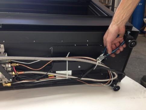
18 8. Instructions for the Mertik Maxitrol GV60 and the Remote Control: Page 18 Ensure that the fuel supplied to the unit is clean and free from particles and moisture. Before a gas supply pipe (new or existing) is connected to the main gas pipe at the gas meter and to the gas control block of the unit, clean and dry compressed air should been blown through it. Cut copper pipes as well as aluminium pilot pipes must be deburred and blown clean before they are connected. The dust filter at the connection to the gas control block will only filter out the coarsest dirt from the system. Fine particles are still able to reach the inside and may damage and/or adversely affect regulation in the gas control block. Heat, moisture and dust are a threat to all electronic components Protect the electronic gas control until all construction, plastering and paintwork has been completed. If such work cannot be avoided, then protect the control against dirt and moisture penetration by using, for example, plastic film. Warning Electronic components will become permanently faulty when exposed to temperatures higher than 60 C. Standard AA batteries will crack open at temperatures >54 C and the battery contents will damage the electronic switches located underneath. Batteries last longest at <25 C. At >50 C the life span is around 23 weeks, this makes the use of the gas fire unnecessarily expensive. Only install the gas control block and receiver as pre-installed at the factory Remember that components may have to be replaced or that repairs may have to be performed at a later date. This may be more difficult if the control is installed using a method that is different from the instructions provided here. Please note! Only place the batteries after wiring to the receiver, gas control block and pilot set is connected. Premature connection to the energy source may damage the control s CPU (central processor). Ensure that the ignition cable is not near the antenna wire and that they do not cross each other. The high voltage released at ignition may damage the sensitive receiver circuit. This may mean that the unit becomes less responsive or not responsive at all to handset commands. (See photograph 1 on page 16) If the manual transmitter range is too limited, loosen the antenna wire from the terminals on the receiver box. Direct the antenna wire away from the ignition cable and in the direction of the control box door. Ensure there is no contact with metal components. Ensure there is no damage to the connection to electronic components or to the wire itself. (See photograph 1 on page 19) Connect the wires correctly to the contact breaker behind the gas control block. The shortest wire runs immediately back to the 1/0 switch and can be found nearest to the back of the gas control block. The longest wire runs to one of the two connections on the receiver box and only fits on one of the screws. Do not tighten the contact breaker and the thermocouple connection too tightly on the gas control block or to each other. It is sufficient to tighten by hand and add a half a turn with an open-end spanner. Tightening too much will break the connection to the magnetic coil below and/or the insulation around the aluminium contact pin in the contact breaker. This may lead to the magnetic coil not opening the gas supply to the pilot and the unit not working.


19 Page 19 Do not extend the thermocouple supplied to the pilot set Extending the thermocouple beyond its limit will lead to a reduction in voltage. This may, in turn, lead to the magnetic coil not being activated. Do not extend the thermocouple supplied to the pilot set Extending the thermocouple beyond its limit will lead to a reduction in voltage. This may, in turn, lead to the magnetic coil not being activated. The receiver and the control units on the gas control block should be switched on to ensure automatic start-up through the manual transmitter. The oval disk on the gas control block should be turned to the ON position. The 1/0 switch should be set to 1. See photograph 2. The ignition cable should be connected to the SPARK connection point on the receiver box. See photograph 1. The manual transmitter has to communicate with the receiver. This has to be learnt. Press the RESET button using a blunt object. (See photograph 3.) Continue to press this button until you hear a short beeping sound, followed immediately by a long beeping signal. Release the button. Direct the manual transmitter towards the receiver and press the arrow down until you hear a long beeping sound. The gas control button will now move for a short period. The manual transmitter has now learned the setting with regard to the receiver and the unit can now be ignited using the remote control. If the manual transmitter is still not communicating with the receiver, repeat the procedure again. The system s thermostat sensor is in the manual transmitter. The manual transmitter operates best at a distance of 2 or 3 metres from the unit. Although communication occurs via short wave radio signals, it is recommended to place the hand transmitter in view of the gas apparatus in a place where the user wishes to experience a pleasant temperature. Do not place the manual transmitter in direct sunlight or other warm location. The thermostat measures the temperature and regulates the flame size of the gas unit accordingly. Remove the batteries only with the red ribbon underneath the batteries, not with a metal tool Removing batteries with a metal object may damage the electronic control permanently. Photo 1 Photo 2 40 mm Photo 3
20 8.1 Mertik GV60 Troubleshooting Flow Chart Page 20 No ACTION Possible problem/cause Solution 1. Option: wall switch START: press ON button > wall switch works. NO Bent pin on switch, or cable not operating properly. Straighten pin, replace wall switch or cable. 1. Manual transmitter START: press both buttons to start ignition sequence. Beep will occur each second NO Manual transmitter battery low. Replace battery, 1.5V AAA quality alkaline! Receiver batteries low. Optional mains adapter not operating properly. Check coding of transmitter and receiver. Replace batteries, 1.5V AA quality alkaline! Check mains adapter. Learn in new code, see instructions and label on receiver. OK Transmitter/receiver range limited. Optional wall switch / cabling not operating properly. Receiver fuse blown (in older versions only). 1. Move antenna cable, see instructions. 2. Replace receiver. Replace wall switch / cabling. Replace receiver. 2. Magnet unit in gas valve is energised (audible click) NO No beep Impulse magnet not operating properly. Replace gas valve. NO 3 short beeps Receiver batteries low. Replace batteries, 1.5V AA quality alkaline! NO 1 long beep ON/OFF switch on gas valve in OFF position 8-wire cable between receiver and gas valve defective / poor contact. Set switch to ON. Check cable, especially in case of plug connection. OK Switch cable disconnected. Check switch cable, see fig. 1 on page 18 Motor not operating properly. Replace gas valve. Micro switch on gas valve not operating properly. Replace gas valve.
. Spark will occur each second. NO IGN sequence stops, no pilot flame. No reaction to transmitter command (receiver does not react).")
21 Page 21 No ACTION Possible problem/cause Solution 3. NO Ignition components not operating properly. Check connection between cable & IGN electrode. Check IGN electrode spark gap. Check IGN electrode for discharge to ground (break in ceramic). Spark will occur each second. NO IGN sequence stops, no pilot flame. No reaction to transmitter command (receiver does not react). Check IGN cable for damage Increase distance between IGN cable and all metal parts. Check that spark does not discharge to ground at location of spark plug connection. Shorten cable if possible. If applicable, provide extra insulation with silicon hose etc. Press RESET button, see instructions. Add ground wire between pilot burner and gas valve. Do not coil the IGN cable. Shorten IGN cable if possible. OK NO IGN sequence stops, no pilot flame. Transmitter command is possible. IGN sequence stops, no pilot flame. Transmitter command is possible. 4. Pilot lit. NO TC and SW cable reversed. Check connection of cable to receiver and interrupter, see fig. 1. Impulse magnet not operating properly. Short between interrupter and SW cable. Replace gas valve. Check connection to interrupter. OK No gas (magnet unit drops after 30 second audible count). Check gas supply to gas valve. Interrupter Receiver 5. Sparking stops after pilot is lit NO Short between interrupter and TC cable. Check connection to interrupter, see fig. 1 OK Electronic measuring amplifier defective. Replace receiver.
22 Page 22 No ACTION Possible problem/cause Solution 6. NO Resistance in thermo current circuit too high. Motor turns to main gas and pilot stays lit. Magnet unit drops (audible click) Not enough heat on thermocouple. Low voltage from thermocouple. Short because thermocouple end is damaged. Check cables and connections in thermo current circuit. Check position of pilot to thermocouple and intensity of pilot flame. Check connections and, if necessary, replace thermocouple. Do not overtighten the connections! Replace thermocouple, do not overtighten the connections! NO IGN sequence stops. No reaction to transmitter command (receiver does not react). Press RESET button, see instructions. OK Add ground wire between pilot burner and gas valve. Do not coil the IGN cable. Shorten IGN cable if possible. 7. Main burner is lit. NO Gas valve manual knob in MAN position. Turn knob to ON position. OK 8. Main burner stays lit. NO Too much / too little air flow / draft at pilot, blows out or is smothered. OK Check whether restriction plate has been correctly applied in unit, see instructions. Poor flue location, check correctness of layout and connections. 9. Magnet unit drops while motor turns. 3 beeps NO Receiver batteries low. Replace batteries, 1.5V AA quality alkaline! System can be switched OFF via remote control. NO System can be switched OFF via ON/OFF switch. NO Short between TC and SW cable. Check connection to interrupter block. YES YES OK OK Replace gas valve.
23 Page 23
24 9.0 MAINTENANCE CHECK LIST Page 24 Fitter details: Name Address Unit serial number Date of purchase Installation date Comments Service and maintenance log book: Service date Performed by Work activities performed
25 10. Maintenance activities.. Please note: turn off the gas supply and power supply as much as possible during maintenance activities. Maintenance activities should be performed by a qualified fitter. Close the gas tap while maintenance activities are being performed. Page 25 Inspect Work activities OK 1 General inspection a The main burner should ignite smoothly (within several seconds) and not give a bang sound due to delayed ignition. Go to number 7 if there appears to be delayed ignition. b Check the flame image. No flames against the glass. The flame image should be stable. The flame should be yellow after approximately 15 minutes; go to number 7 if the flame image is blue. c Check for excessive formation of soot on the inside of the glass/combustion chamber and on decorative parts. Go to number 7 if there is excessive formation of soot. 2 Door/front a check for obstructions in the convection air openings 3 Glass window, seal. a check the glass window for cracks etc. Replace if damaged, cracked, or broken. b check the seal of the glass window; this needs to join the unit and glass window. Replace if required. c check any hinges, seals, quadrants etc. d clean the glass. Check there is an even (not too large) load on the glass window. Prevent point load. 4 Gas control compartment and convection part of the unit a clean these areas with a vacuum cleaner. Do so carefully. Remove parts that do not belong here. b check if the convection airflow is free. 5 Decorative parts (logs/ a remove decorative parts and clean the burner (be careful with ceramic burners!) with a vacuum pebbles etc.) and cleaner. (pilot) burner b inspect decorative parts for damage/cracks/discolouration and clean with a soft brush if required. c check if the burner cover is intact and free of corrosion. Replace the burner if required. d after completing the inspection: replace decorative parts, exactly as stipulated by the manufacturer. Ensure the pilot burner is kept free! e check if the pilot flame protection is intact (if applicable). f check the piezo for sufficient spark power, and ensure the ignition cable is free from metal parts/ electrical parts. 6 Combustion chamber a check the condition of the finishing, such as varnish and enamel. Check for corrosion. Repair if required. b replace the unit if there are holes. Close the unit for further use. c check overpressure hatches or overpressure construction for sealing and sufficient movement/deposits. 7 Ignition and operation of the main burner a remove the burner from the unit and check whether the main injector is dirt-free. b check if the primary ventilation opening in the main burner is dirt-free. c mount the burner and check if the burner is in a good position in relation to the pilot burner. d check if the burner is fixed and cannot move. e check if the pilot burner burns well, with a blue flame (blue only). f check if the burner ignites uniformly across the entire surface and without significant delay. g check if the flame image is uniform and stable. h check the initial and burner pressure. Do not forget to close the pressure measuring points. i check if gas control parts are intact, and that plastic parts have not melted, for example. j check electrical wiring for damage and ensure they are away from hot parts of the unit. 8 Installation a check if convection grates are dust-free and dirt-free. b check if there is sufficient distance between the unit and flammable furniture. 9 Flue tube/air supply a where possible, inspect the general state of the exhaust/supply system and check for blockages / leaks / corrosion. b check the outlet, which should be free from dirt and blockages. c check the outlet, which should be free from dirt and blockages. 10 Remote control a check for correct functioning of the remote control. 11 Ventilators (if present) a clean the convection ventilators and check for correct functioning.
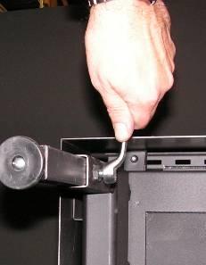
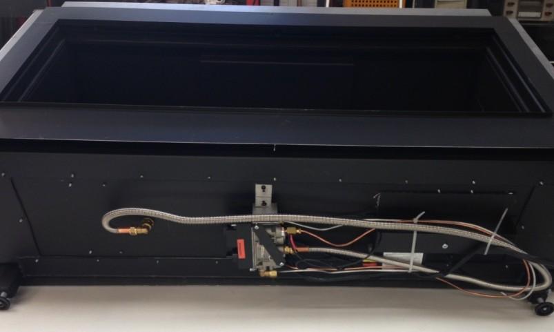
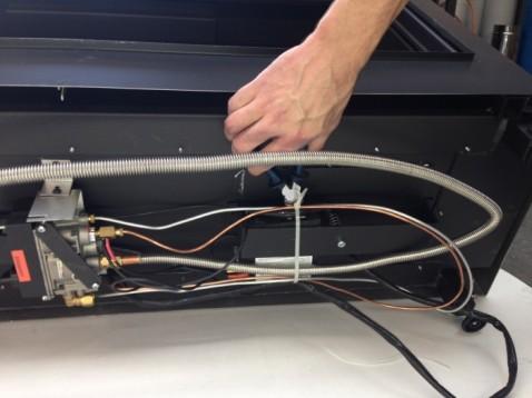
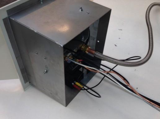
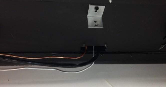
26 11. PLACING THE UNIT (first read General instructions ) Please note: Before placing the unit, we recommend you first read Chapter 7 Concentric flue system on page Connection to the gas pipes (see page 28 for details) Page 26 You can determine where the gas pipes will be placed, dependent on the layout. Ensure control equipment is not twisted during installation and there is no excessive tension. Accessibility of various connection points in relation to components need to be maintained. After installation, check the connections for tightness in relation to gas. Use a 1/2 gas tap with connection. Ensure the gas pipes are dirt-free and sand-free, and gas and combustion products from various parts and functioning is correct. The gas connection should only be undertaken when the electricity supply is disconnected. This prevents any damage occurring to the gas control equipment Preparation and installation of the unit Remove the packaging and check the unit for possible damage. Please note: place the unit on a stable surface. Do not place the unit on its back or on its side! Place the unit at the installation location One side window should now be removed in order to take the additional parts out of the unit. Remove the decorative frames on the bottom, and rear respectively of the relevant window and loosen the set screw on the front and 1side. Remove the glass strip gently from his seat possibly with a screwdriver. See example on Page.37 Figure I and J With the supplied suction cup you can remove the windows easily. Take hold of the front window by its sides and move it CAREFULLY upwards, then CAREFULLY and slowly pull the bottom of the window towards you. Next, lower the window and leave it in a safe place where it cannot be broken or damaged. Please note: the window is very fragile. You should therefore be very careful when (re)installing the window. See example on Page.37 Figure K Next, take the packaged components out of the unit and check to make sure they are not damaged or broken. Situate the unit (see page 36 figures F, G and H as an example of an installation location) in your chosen installation location. The device must be attached directly to the rear wall (mounting material not included). Install the supplied convection grilles at least 50 cm below the ceiling on the appropriate wall. A lowered ceiling inside the whole structure could be a possible solution in the event of a situation with a visual obstruction. The legs (page 37, figure L) of the unit can be adjusted, and if necessary shortened, see also dimensional drawing on page 35. The adjustable feet allow fine adjustments (levelling) to be made. You must keep aware with the installation and the height of the gas cartridge frame Installing gas control GV60 (see page 37 and 38 figures M to T) Gas pipe, thermocouple and ignition cables have been placed in coils under the unit. The gas valve including the burner control must be fitted by the installer in the gas cartridge. The following step by step procedure: 1. After the windows are taken away and parts inside the gas fire are taken out; place the complete gas fire carefully on the backside. You can use the wooden pallet to support the gas fire. 2. Cut the binders and CAREFULLY unroll the various lines and cables to the position where the gas control cassette is to be placed. (see page 37 figure I ) 3. Remove the screw holding gas valve bracket ( see page 38 figure O ) and carefully take away the gas valve and move it to the side of the gas fire where you want to install the gas cassette. 4. Guide all tubes carefully so that sharp bending is prevented. 5. Position the gas valve on the correct position on the backside of the gas cassette. (see page 38 figure P and Q ) 6. Mount the gas valve including bracket inside the gas cassette, fix it with the 2 winged nuts inside. Slide the burner control in the bracket. (see page 38 figure S ) 7. Position the complete gas cassette in the surrounding construction of the gas fire. Be aware of the maximum distance between gas fire and gas cassette limited by the length of thermocouple etc. 8. Make sure that the tubes, ignition cable and thermocouple are mounted without tensile stress and sharpness 9. After connecting the main gas supply, flue liner and before starting the build-up of the construction around the gas fire: check all gas connections on leakage and make a test run to determine the proper functioning of the gas fire installation.

 Attention! Before placing ceramic log inset, you have to change the the 2 aeration brackets under the double burner.")
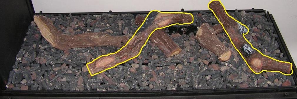
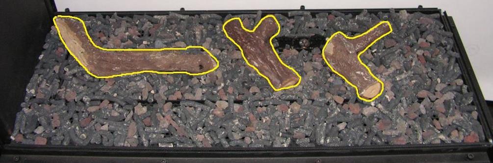
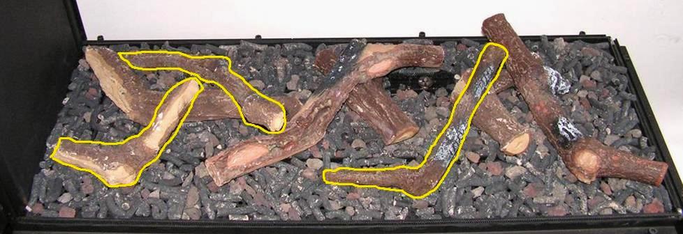
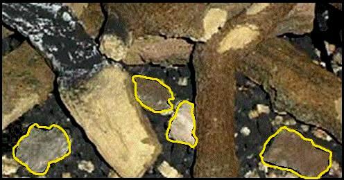
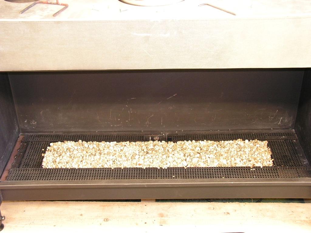
27 11.4 Installation and assembly of the CC flue system with accessories. See Chapter 7 Concentric flue system on Page 14 and the "Concentric paths Table" on page 31. * It is also possible to install the fire using fireproof plate 50 mm Superisol. (See installation example on p.36 Fig. A, B and C) * After installing the fireplace and the various connections have been made and also checked for leaks and proper operation of equipment required, the logs should be placed next Fitting the ceramic log inset (see page 39 to 41) Attention! Before placing ceramic log inset, you have to change the the 2 aeration brackets under the double burner. This all for an optimal view of the fire at gas category G mbar.(I2E, I2E + I2H,) Method: * Remove decorative plate and burner out of the burning chamber. * Unscrew the Aeration bracket with two holes Ø 9 mm from the burner. * Place the Aeration bracket for G25 with two holes Ø 5 mm * Place screws back in place. * Place burner and decorations back in place. * The burner pressure, and the injector do not need to be altered. Page 27 Please note: when installing the log set and the various glowing materials and accessories, the following must be taken into account: A: Keep the opening between the burner and the burner plate free of glowing material B: Ceramic materials should not come into contact with the cord of the window fixture. Remove this if necessary. The window may otherwise be damaged. Mix the glowing material (lava granules) and the fusilli (spiral-shaped ceramic material) and spread them evenly over the burner and the burner plate so that they are just covered. Glowing embers can be placed here and there as decoration. * There should be no glowing material in or on the pilot burner. NOTE: the remaining material can be discarded. The use of too much glowing material can adversely affect the combustion process. * Place the ceramic wood blocks in the correct order as shown on Page 39 and 40. * Place the logs carefully. Other location can seriously affect the flames or malfunction of the burn process (explode) * Before replacing the windows make sure if there must be a restriction plate to be placed or not. See page 14 and "Table of concentric path" on page 31 * If there is a restriction is required for your situation, remove the baffle plate by unscrewing it from the front of the plate after the plate backwards and then out to be taken. Now install the restrictor plate with two screws and replace the baffle plate. * Now place the two windows in reverse order as described on page 26. Incorrectly installed ceramic wood blocks and glowing material may have a significant influence on the fire image and the burning effect Fitting the optional pebble set (see page 41) * Scatter vermiculite evenly over the burner tray. Make sure the pilot light remains unobstructed. * Place a row of medium-sized and large pebbles at the front of the burner plate * Fill the burner tray with small and medium-sized pebbles from the front to the rear. Place the pebbles as closely as possible to each other on the burner tray. * Fill the rear of the burner plate with medium-sized and large pebbles. MAKE SURE THE PILOT LIGHT REMAINS UNOBSTRUCTED! * Before replacing the window make sure if there must be a restriction plate to be placed or not. See page 14 and "Table of concentric path" on page 31 * If there is a restriction is required for your situation, remove the baffle plate by unscrewing it from the front of the plate after the plate backwards and then out to be taken. Now install the restrictor plate with two screws and replace the baffle plate. * Now place the two windows in reverse order as described on page 26.

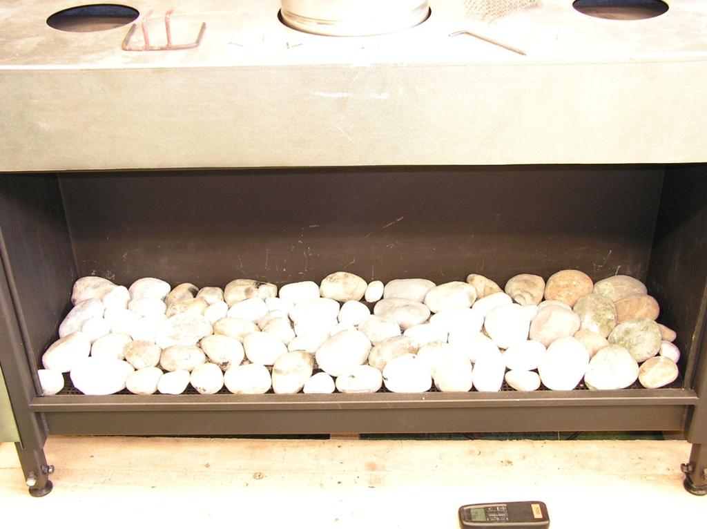
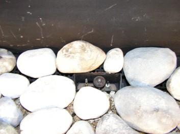
28 11.7 Fitting the optional Carrara / Basalt stones (see page 41) * Scatter vermiculite evenly over the burner tray. Make sure the pilot light remains unobstructed. * Fill the burner tray and burner plate neatly and evenly with the Carrara stones. MAKE SURE THE PILOT LIGHT REMAINS UNOBSTRUCTED! Page 28 * Reinstall the window, following the instructions for removing it in reverse order. * Before replacing the window make sure if there must be a restriction plate to be placed or not. See page 14 and "Table of concentric path" on page 31 * If there is a restriction is required for your situation, remove the baffle plate by unscrewing it from the front of the plate after the plate backwards and then out to be taken. Now install the restrictor plate with two screws and replace the baffle plate. * Now place the two windows in reverse order as described on page TECHNICAL DETAILS GV60 Model : 1050 Gas block type : Mertik GV60 Ignition : Distance operation and Piezo ignition Gas connection : 3/8" (Internal) A=Gas intake B=Gas exhaust C=Thermocouple connection D=Pilot burner connection Unit category : C11-C31-C91 Pilot flame : SIT 3 flames Combustion gas discharge and Combustion air supply : Concentric: Ø130 / 200 mm A B C A= D= Pilot burner connection D =B C= Thermocouple connection
29 12.1 Gas-technical specifications 1050 GAS TYPE CATEGORY G20 I2H/I2E/I2E+ G25 I2l/I2ELL G30/31 I3+ G30 I3B/P Page 29 PRIMARY AIR PRE-PRESSURE BURNER PRESSURE HIGH BURNER PRESSURE LOW INJECTOR BORE PILOT INJECTOR LOW CLASS BORE LOAD Hs LOAD Hi CONSUMPTION NOM.POWER MBAR MBAR MBAR Ø MM CODE MM KW KW M³/h kw 2x Ø9 2x Ø5 3x Ø16 3x Ø / / / / / / / / / / / / / / Appliance has NoX class 5 AT I2H, I3B/P BE I2E+, I3+ DK I2H, I3B/P DE I2ELL, I3B/P FI I2H, I3B/P FR I2E+, I3+ GR I2H, I3B/P GB I2H, I3+ IS I3B/P IE I2H, I3+ IT I2H, I3+ LU I2E, I3B/P NL I2L, I3B/P NO I3B/P PT I2H, I3+ ES I2H, I3+ SE I2H, I3B/P CY I3B/P,I3+ EE I3B/P,I2H LT I3B/P,I2H LV I3B/P,I2H MT I3B/P, HU I3B/P,I2H PL I3B/P SI I3B/P,I2H SK I2H
30 14. PROBLEMS AND POSSIBLE SOLUTIONS Please first check if all guidelines were followed before attempting to solve any problems with the unit. Warning: Page 30 Solving problems with your unit, whether gas related or electrical, must always be performed by a qualified technician. SYMPTOM The pilot flame will not light after repeated ignition. The pilot flame will not remain alight after ignition. The main burner goes out when the unit is warm. Soot deposits on the glass. Sharp blue flames that are released by the burner or a pilot that burns too wildly. ACTION TO BE TAKEN 1. There is air in the pipes if you switch the unit on for the first time or after a service. It will take a little while until all the air has flowed out of the pipes and gas flows through that can be ignited. Take it away and try to switch the pilot flame on several times in order to allow the air to escape. 2. See whether the gas pipe to the unit is open and if there is sufficient gas pressure to the unit. 3. Check whether there are sparks between the spark electrode and the pilot. If there are no sparks: a) Check whether the connection between the electrode and the ignition is broken or faulty. b) Check whether the spark short circuits at another point or jumps. c) Check whether the electrode is broken. 1. Check whether the pilot flame is large enough to burn around the thermocouple. If the flame is too small, you need to check the gas feed pressure. If the size of the pilot flame cannot be adjusted, there may be an obstruction in the pilot. 2. Check whether the thermocouple interrupter is connected to the gas valve properly. 3. Check that the gas valve is not faulty. 4. Check whether the restriction plate has been placed according to instructions (see page 31). 1. This can be a normal effect of the thermostat. Check whether the pilot flame is able to heat the thermocouple adequately. If the pilot flame is too small then the gas pipe or the pilot flame adjustment need to be checked. 2. Check whether the restriction plate has been placed according to instructions (see page 31). 1. Check whether the lavasplit is lying on the burner in the correct manner. 2. Check if the pilot burner is free from burner filling. 3. Check whether there is any blockage in the burner openings. 4. Check if the flue tube is functioning correctly and if the flue tube is not hindered or blocked. 5. Check the pipe pressure. 1. Check whether the restriction plate has been used. Weak (stifling) pilot flame. 1. Check the pilot burner pressure or duct pathway. Main burner will not burn after the pilot burner is functioning. 1. Check if the motor button turns and whether the batteries are empty. 2. Possible defect in the gas block. 3. Check whether the pilot flame ignites the burner well. 4. Check that the burner opening is not blocked.
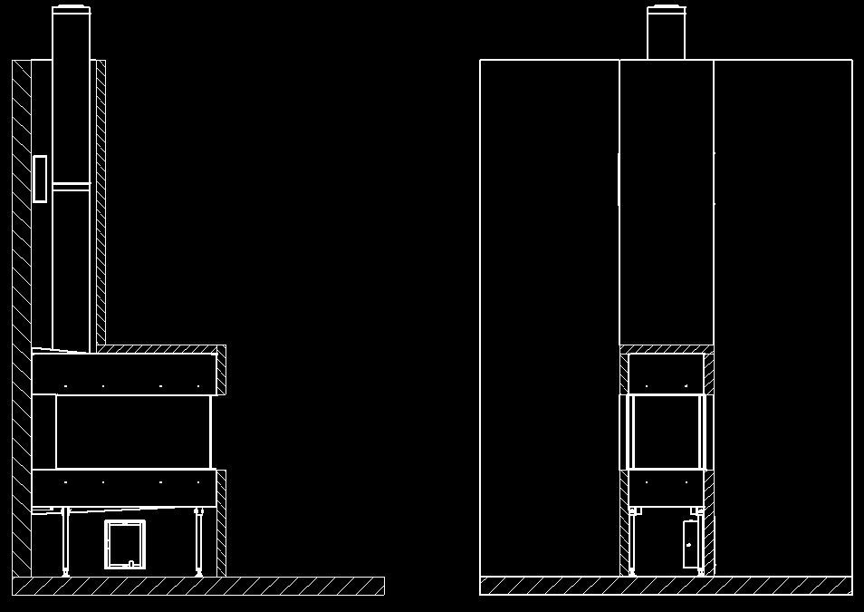
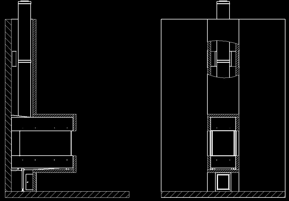
31 Table of concentric pathways Pathway Illustration X totaal in Y totaal in Restriction metres metres min* max* min* max* 85R Pag.31 Indirect exterior wall outlet A-B Roof pass-through without slope C 2 12 from 2 meter Roof pass-through with 45º slope** D from 3 meter Roof pass-through with 90º slope*** E from 3 meter 45 bend: calculation length 1 metre 90 bend: calculation length 2 metres * length excluding roof or exterior wall outlets. Always adhere to a starting length of 1 metre! for NG appliances ** length excluding roof or exterior wall outlets. Always adhere to a starting length of 1 metre! for LPG appliances *** Vertical: horizontal ratio X + X1 + X2 : Y 2 : 1 **** Vertical: horizontal ratio X + X1 : Y 2 : 1 Determination of restriction: Wall pass-through - 1 metre vertical, 90 bend, max. 5 metres horizontal, Wall pass-through no restriction. Roof pass-through - 2 to 4 metres vertical + roof pass-through, fit 30 mm restriction plate. Roof pass-through - 4 to 7 metres vertical + roof pass-through, fit 55 mm restriction plate. Roof pass-through - 7 to 12 metres vertical + roof pass-through, fit 70 mm restriction plate. Y Y A X X B X1 X C X D Y E


32 Pag.32 THC-CC Pipe Diameter A B L1 LW /500/ /448/ /500/ /448/946 THC-CC Adjustable pipe Diameter A B THC-CC Bend Diameter A B L1 L2 C /30/ /30/45 THC-CC Bend 90 Diameter A B L1 L2 L3 L4 L THC-CC Reducer diam THC-CC Clamping strips Diameter A THC-CC Wall bracket adjustable Diameter A B C


33 Pag.33 THC-CC Ceiling support Diameter A B THC-CC Roof support Diameter A B THC-CC Bracket Diameter A THC-CC Centering plate Diameter A B THC-CC Centering plate adjustable Diameter A B C THC-CC Roofing sheet sloping 0-10 Diameter A B THC-CC Roofing sheet sloping 5-25 Diameter A B
 Diameter A 100-150 160")


34 THC-CC Roofing sheet sloping (LEAD) Diameter A Pag.34 THC-CC Roofing sheet sloping (LEAD) Diameter A THC-CC Storm collar Diameter A B THC-CC Roof pass-through Diameter THC-CC Wall pas-through Diameter THC-CC Renovation Packet Diameter
35 Pag.35


36 A Pag.33 B C


37 Pag.37 I J K L M GAS CONTROL BLOCK N RECEIVER GAS CONTROL BLOCK


38 Pag.38 O P GAS CONTROL BOX Q R S T POSITION PILOT BURNER

39 Pag.39

40 Pag.40


41 Pag.41 Pebles Basalt / Carara
OPERATING AND INSTALLATION INSTRUCTIONS Trimline 2050 OH
 UNITED KINGDOM-UK OPERATING AND INSTALLATION INSTRUCTIONS Page 1 1080 Trimline 2050 OH TABLE OF CONTENTS 1. General Page 3 1.1 Contents of the package 2. Safety of the unit Page 4 2.1 Safety 3. Remote
OPERATING AND INSTALLATION INSTRUCTIONS
 OPERATING AND INSTALLATION INSTRUCTIONS Page.1 1036 / 1037 / 1038 / 1039 Trimline 100 (1036) Trimline 120 (1037) Trimline Tunnel 120 (1038) Trimline 140 (1039) GREAT BRITTAN-GB IRELAND-IE OPERATING AND
CONVENTIONAL FLUE INSTALLATION INSTRUCTIONS DARWIN CONVENTIONAL FLUE GAS STOVE
 CONVENTIONAL FLUE INSTALLATION INSTRUCTIONS DARWIN CONVENTIONAL FLUE GAS STOVE DBF - REV A - 09/18 CONTENTS 1.0 USER INSTRUCTIONS - REMOTE CONTROL Page 3 1.1 General 1.2 Manual transmitter 1.3 Screen setup
OPERATING AND INSTALLATION INSTRUCTIONS / 1034 Trimline 73 (1033) Trimline 73H (1034)
 Trimline 73H (1034)") Page.1 OPERATING AND INSTALLATION INSTRUCTIONS 1033 / 1034 Trimline 73 (1033) Trimline 73H (1034) GREAT BRITTAN-GB IRELAND-IE OPERATING AND INSTALLATION INSTRUCTIONS Page.2 TABLE OF CONTENTS 1. General
Page.1 OPERATING AND INSTALLATION INSTRUCTIONS 1033 / 1034 Trimline 73 (1033) Trimline 73H (1034) GREAT BRITTAN-GB IRELAND-IE OPERATING AND INSTALLATION INSTRUCTIONS Page.2 TABLE OF CONTENTS 1. General
OPERATING AND INSTALLATION INSTRUCTIONS. Gas-fired hearth: TRANSPARENTE
 Page.1 OPERATING AND INSTALLATION INSTRUCTIONS Gas-fired hearth: TRANSPARENTE 73-100-120-140-160 GREAT BRITTAN-GB IRELAND-IE 1. GENERAL Page 3 Note Warning Maintenance Package contents Page.2 2. APPLIANCE
Clear Installation guide
 Clear 40010631-0938 ENG Installation guide ENG 1.1 1.2 1.3 A 1.4 1.5 1 < < < < A B 2.1 2.2 2.3 C 2.4 2.5 2 < < < < 3.1 3.2 3-3 3 < < < < Inhoudsopgave 1 Introduction... 6 2 Safety instructions... 6 3 Installation
OPERATING AND INSTALLATION INSTRUCTIONS. Gas-fired hearth: TRANSPARENTE
 Page.1 OPERATING AND INSTALLATION INSTRUCTIONS Gas-fired hearth: TRANSPARENTE 73-100-120-140-160 GREAT BRITTAN-GB IRELAND-IE 1. GENERAL Page 3 Note Warning Maintenance Package contents Page.2 2. APPLIANCE
Fyn Installation guide
 Fyn 450 400100929-1114 ENG Installation guide ENG 1.1 1.2 A B 1.3 1.4 1 < < < < 2.1 2.2 2.3 3.1 3.2 2 < < < < 4.1 4.2 4.3 4.4 3 < < < < Table of contents 1 Introduction... 6 2 Safety instructions... 6
Solution Installation guide
 Solution 40011444-1327 ENG Installation guide ENG 1-1 1-2 1-3 1.4 1 < < < < 2.1 2-3 2-4 2 < < < < 3-1 3.2 3-3 3.5 3.6 3 < < < < 4-1 A 4-2 4-3 4 < < < < Dimensions Terminal position Distance (For good working
Fyn Installation guide
 Fyn 600 4001131-1123 ENG Installation guide ENG 1.1 1.2 A B 1.3 1.4 1 < < < < 2.1 2.2 2.3 2.4 3.1 3.2 2 < < < < 4.1 4.2 4.3 4.4 3 < < < < 1 Introduction The appliance can only be installed by a competent
Installation & Troubleshooting Requirements
 Installation & Troubleshooting Requirements Wiring Diagram Operation Sequence Presumptions: Main valve knob should always remain in the ON position Gas is bled to the valve Electrical is properly connected
Duet XL /0929. Installation guide
 Duet XL 40010749/0929 ENG Installation guide ENG 1.1 1.2 1.3 1.4 1.5 A 1.6 1.7 1 < < < < B A 2.1 2.2 2.3 2.4 2 < < < < 2.5 2.6 2.7 2.8 3 < < < < 3.1 F F 3.2 3.3 4 < < < < Table of contents 1 Introduction...
User manual (GB / IE) for appliances provided with an electronic ignition on the remote control. English. Read this document and store it carefully
 for appliances provided with an electronic ignition on the remote control. English. Read this document and store it carefully") User manual (GB / IE) for appliances provided with an electronic ignition on the remote control Read this document and store it carefully 958.007.07.uk 1 UK Contents page Preface 2 1. Introduction 3 2.
User manual (GB / IE) for appliances provided with an electronic ignition on the remote control Read this document and store it carefully 958.007.07.uk 1 UK Contents page Preface 2 1. Introduction 3 2.
VASKA C11. gas-fireplace user manual. Saturnus 8 NL-8448 CC Heerenveen Postbus 219 NL-8440 AE Heerenveen T. +31(0) F.
 F.") VASKA C11 gas-fireplace user manual Saturnus 8 NL-8448 CC Heerenveen Postbus 219 NL-8440 AE Heerenveen T. +31(0)513 656500 F. +31(0)513 656501 40 010 458 01.51 DESCRIPTION OF THE FIREPLACE CONTENTS 1 2
VASKA C11 gas-fireplace user manual Saturnus 8 NL-8448 CC Heerenveen Postbus 219 NL-8440 AE Heerenveen T. +31(0)513 656500 F. +31(0)513 656501 40 010 458 01.51 DESCRIPTION OF THE FIREPLACE CONTENTS 1 2
Installation Instructions Horizon Natural Draft Electronic Ignition Gas Fireplaces
 Installation Instructions Horizon Natural Draft Electronic Ignition Gas Fireplaces Installation Instructions Horizon Natural Draft Electronic Ignition 3 Sided Gas Fireplaces Natural Draft Electronic Ignition
Respect OC Installation manual
 Respect OC 40011335-1235 ENG Installation manual ENG 1.1 1.2 A 1.3 1.4 A A 2.1 2.2 2.3 1 < < < < 2.4 2.5 B C A B A 2.6 2 < < < < 3.1 3.2 3.3 3.4 3.5 3.6 3 < < < < A B 3.7 4 < < < < L A A 4.1 A A 4.2 A
Relaxed Premium M Relaxed Premium M ENG
 Relaxed Premium M 40010959 1440 Relaxed Premium M ENG 3 alternative finishes. 1.1a 1.1b 1.1c 1 < < < < 1.2 1.3 7 1.4 2 < < < < 1.5 1.6 B 1.9 3 < < < < 2.1 2.2 2.3 3.1 3.2 3.3 3.4 4 < < < < 3.5 4.1 4.2
Kalahari DECORATIVE FUEL EFFECT GAS FIRE
 Kalahari DECORATIVE FUEL EFFECT GAS FIRE User Instructions These instructions should be read by the user before operating the appliance and retained for future reference Model No. KRDC00MN & KRDC00SN are
Vaska Logburner. voorbeeld Installation guide
 Vaska ogburner voorbeeld 40010627-2103 ENG Installation guide ENG 1.1 1.2 1.3 1.4 1.5 1 < < < < 1 Introduction The appliance can only be installed by a competent person in accordance with the Gas Safety.
PROBLEM CAUSE SOLUTION
 ------------------------------------------------------------------------------------------------------------------------------------------------- Troubleshooting Installer Only PROBLEM CAUSE SOLUTION Delayed
INSTRUCTIONS FOR USE & MANUAL DAILY MAINTENANCE UNICA Gas fi re with open combustion system
 INSTRUCTIS FOR USE & MANUAL DAILY MAINTENANCE UNICA-2 75 Gas fi re with open combustion system Bellfi res wishes you many cosy evenings with your new Bellfi res gas fi re This document is an essential
VASKA B11. gas -fireplace installation guide
 VASKA B11 gas -fireplace installation guide Saturnus 8 NL-8448 CC Heerenveen Postbus 219 NL-8440 AE Heerenveen T. +31(0)513 656500 F. +31(0)513 656501 40 010 446 01 51 DESCRIPTION OF THE FIREPLACE CONTENTS
BOAFOCUS INSTALLATION, SERVICING AND USER INSTRUCTIONS
 BOAFOCUS INSTALLATION, SERVICING AND USER INSTRUCTIONS Content General Notes General Notes User instructions EMERGENCY GAS ISOLATION FIRST TIME OF OPERATION OPERATING INSTRUCTIONS A. GENERAL NOTES B. SETTING
CRYSTAL FIRES. Inset Conventional Flue Fire. (BOSTON/MIAMI) Cf1 and MANHATTAN USER INSTALLATION AND SERVICING INSTRUCTIONS
 Cf1 and MANHATTAN USER INSTALLATION AND SERVICING INSTRUCTIONS") CRYSTAL FIRES (BOSTON/MIAMI) Cf1 and MANHATTAN Inset Conventional Flue Fire USER INSTALLATION AND SERVICING INSTRUCTIONS FOR USE WITH NATURAL GAS G20 @ 20 mbar For use in GB and IE CE THESE INSTRUCTIONS
CRYSTAL FIRES (BOSTON/MIAMI) Cf1 and MANHATTAN Inset Conventional Flue Fire USER INSTALLATION AND SERVICING INSTRUCTIONS FOR USE WITH NATURAL GAS G20 @ 20 mbar For use in GB and IE CE THESE INSTRUCTIONS
Wall-mounted Gas Fires. 39 Portrait INSTALLATION,USER & SERVICING INSTRUCTIONS (TO BE LEFT WITH THE CUSTOMER) UK & IRELAND
 UK & IRELAND") Wall-mounted Gas Fires 39 Portrait INSTALLATION,USER & SERVICING INSTRUCTIONS (TO BE LEFT WITH THE CUSTOMER) UK & IRELAND UK IE INSTALLATION INSTRUCTIONS CONTENTS Important Notes Page 2 Commissioning the
Wall-mounted Gas Fires 39 Portrait INSTALLATION,USER & SERVICING INSTRUCTIONS (TO BE LEFT WITH THE CUSTOMER) UK & IRELAND UK IE INSTALLATION INSTRUCTIONS CONTENTS Important Notes Page 2 Commissioning the
Internet Version for Reference Only INDUCED DRAFT COMMERCIAL WATER HEATERS SUPPLEMENT INSTRUCTIONS TO PART #
 INDUCED DRAFT COMMERCIAL WATER HEATERS SUPPLEMENT INSTRUCTIONS TO PART #238-39387-00 THIS INSTRUCTION SUPPLEMENT IS ONLY INTENDED TO GIVE INSTALLATION INSTRUCTIONS AND INFORMATION RELATED TO THE INDUCED
Kalahari RC & Camber RC
 Kalahari RC & Camber RC DECORATIVE FUEL EFFECT GAS FIRE User Instructions These instructions should be read by the user before operating the appliance and retained for future reference Model No s KRDC**RN
GV60 REMOTE CONTROL user guide
 GV60 REMOTE CONTROL user guide 919-713 09.20.16 General Notes... 4 Coding instructions:... 5 To Turn ON Appliance:... 5 To Turn OFF Appliance:... 5 Flame height adjustment... 6 To open and close solenoid
Torch framed Installation Guide
 Torch framed 40010567-0602 Installation Guide 1 2 3 4 1 < < < < 5 6 7 > > > > 2 Content 1 Introduction... 1 2 Safety Instructions... 2 3 Installation requirements... 3 3.1 Rear surface construction...
Installation Manual EF5000 NZ
 Installation Manual EF5000 NZ Important: The appliance shall be installed in accordance with; Local gas fitting regulations Municipal building codes AS/NZS 5601.1.1:2010 Gas Installation Any other relevant
SPECIFICATIONS PART NAME
 SPECIFICATIONS MODEL High HEAT RATING Low FUEL TANK CAPACITY BURNING TIME DIMENSIONS(W x D x H) WEIGHT VOLTAGE / FREQUENCY ELECTRICAL CONSUMPTION LC-S27 9,900 BTU / 2.9 kw 2,900 BTU / 0.8 kw 4.0 lit. 14.2~
Installation Manual EF5000 AUS & NZ
 Installation Manual EF5000 AUS & NZ This manual is ONLY for fires with a serial No. from 80600 to 80999. Important: The appliance shall be installed in accordance with; Local gas fitting regulations Municipal
Duet Premium M Duet Premium M ENG
 Duet Premium M 40011422-1441 Duet Premium M ENG 1.1 1.2 1.3 1.4 1.5 1.6 1.7 1.8 1 < < < < 2.1 a 2.1 b 2.1 c A C 2.2 2 < < < < F F 2.3 X H X C 2.4 2.5 S T 3.1 3.2 R Q 3.3 3 < < < < 4.1 4.2 4.3 4.4 4 <
PowerVent. Installation manual (GB) English. Store this document in a safe place UK
 English. Store this document in a safe place UK") PowerVent Installation manual (GB) Store this document in a safe place 959.034.03.UK GB Contents Blz Foreword 3 1. Introduction 3 2. CE declaration 4 3. SAFETY 4 3.1 General 4 3.2 Regulations 4 3.3 Precautions
PowerVent Installation manual (GB) Store this document in a safe place 959.034.03.UK GB Contents Blz Foreword 3 1. Introduction 3 2. CE declaration 4 3. SAFETY 4 3.1 General 4 3.2 Regulations 4 3.3 Precautions
CATALINA FIRE TABLE ASSEMBLY INSTRUCTIONS
 CATALINA FIRE TABLE ASSEMBLY INSTRUCTIONS CSA Model 98300 DRF01000 Installer: Leave these instructions with consumer. Consumer: Keep these instructions for future reference. DANGER If you smell gas: 1.
VASKA C11. gas -fireplace installation guide
 VASKA C11 gas -fireplace installation guide Saturnus 8 NL-8448 CC Heerenveen Postbus 219 NL-8440 AE Heerenveen T. +31(0)513 656500 F. +31(0)513 656501 40 010 459 01 51 DESCRIPTION OF THE FIREPLACE CONTENTS
USE & MAINTENANCE INSTRUCTIONS FOR NU-FLAME FIREBOXX SYSTEM (NATURAL GAS & LPG) FITTED WITH EVOLUTION PLUS BURNER. FOR DECORATIVE PURPOSES ONLY
 FITTED WITH EVOLUTION PLUS BURNER. FOR DECORATIVE PURPOSES ONLY") Unit 4, Kimpton Trade & Business Centre Minden Road, Sutton, Surrey, SM3 9PF Tel: 020 8254 6802 IMPORTANT NOTE Simulated crushed rock, simulated pebbles, simulated logs, or simulated driftwood, manufactured
Unit 4, Kimpton Trade & Business Centre Minden Road, Sutton, Surrey, SM3 9PF Tel: 020 8254 6802 IMPORTANT NOTE Simulated crushed rock, simulated pebbles, simulated logs, or simulated driftwood, manufactured
INSTALLATION & USERS INSTRUCTIONS. FOR USE WITH NATURAL GAS 20 mbar For use in GB and IE
 1 valentine s buildings Bechers drive Aintree racecourse Business Park L9 5ay CF1 L GAS APPLIANCE INSET CONVENTIONAL FLUED GAS FIRE INSTALLATION & USERS INSTRUCTIONS FOR USE WITH NATURAL GAS G20 @ 20 mbar
JUNEAU JUN. 08/51193/0 Issue 0
 JUNEAU JUN 08/51193/0 Issue 0 The product complies with the European Safety Standards EN60335-2-30 and the European Standard Electromagnetic Compatibility (EMC) EN55014, EN60555-2 and EN60555-3 These cover
USER S, MAINTENANCE and SERVICE INFORMATION MANUAL
 CONTENTS SAFETY INFORMATION................ 2 FOR YOUR SAFETY....................... 2 SYSTEM OPERATION.................. 2 THERMOSTATS.......................... 2 INTERMITTENT IGNITION DEVICE...........
Model 1174 Electric Heater User instructions for LED effect 2kw Inset Heater
 200688_6 Page 1 Model 1174 Electric Heater User instructions for LED effect 2kw Inset Heater These instructions should be read carefully and retained for future reference Important Notes This heater must
User s Manual RA-3030SS RA-3036SS. NOTE: This unit was designed for indoor residential use and DUCTED operation only.
 www.windsterhood.com User s Manual UNDER CABINET SERIES RA-3030SS RA-3036SS NOTE: This unit was designed for indoor residential use and DUCTED operation only. DO NOT USE OVER A WOOD GRILL OR MOUNT OUTDOOR
Emberglow COAL EFFECT BALANCED FLUE GAS FIRE
 Emberglow COAL EFFECT BALANCED FLUE GAS FIRE User Instructions These instructions should be read by the user before operating the appliance and retained for future reference Model No. FEBC00MN is only
Duet Premium L Duet Premium L ENG
 Duet Premium L 40011297-1441 Duet Premium L ENG 1.1 1.2 1.3 1.4 1.5 1.6 1.7 1.8 1 < < < < 2.1 a 2.1 b 2.1 c A C 2.2 2 < < < < F F 2.3 X H X C 2.4 2.5 S T 3.1 3.2 R Q 3.3 3 < < < < 4.1 4.2 4.3 4.4 4 <
C D INSTALLATION 16 INSTALLER GENERAL INFORMATION
 INSTALLATION GENERAL INFORMATION This appliance is sealed from the surrounding environment in which it is installed and consequently combustion air is only aspired from outside! - When installing, NEVER
Dovre 250 Cast Iron Gas Stove
 Dovre 50 Cast Iron Gas Stove NATURAL GAS AND LPG INSTALLATION, SERVICING AND USER INSTRUCTIONS THIS PRODUCT IS FOR USE ONLY IN GREAT BRITAIN AND IRELAND These instructions are to be left with the customer,
MILLA ELECTRIC FIREPLACE
 MILLA ELECTRIC FIREPLACE MODEL NO. 064-3177-0 ASSEMBLY INSTRUCTIONS Toll-free: 1-888-670-6684 IMPORTANT: Please read this manual carefully before beginning assembly of this product. Keep this manual for
Decorative Fuel Effect Appliances
 Decorative Fuel Effect Appliances Technical Manual User and Installation Instructions for CUBB22US Available in Natural Gas. 1 Contents Section Pages 1 Unpacking 3 2 Installation Parameters 4 3 Installation
Fully-automatic Gas tankless Water Heater USER'S MANUAL FOR MODEL EZ-101 ISO9001 certified
 Fully-automatic Gas tankless Water Heater USER'S MANUAL FOR MODEL EZ-101 ISO9001 certified Thank you for purchasing our fully-automatic gas-fired tankless water heater. Please completely read this Manual
Outdoor Tabletop Heater TTH20 Series
 Outdoor Tabletop Heater TTH20 Series FEATURES: The ideal solution for extending the outdoor entertaining season Creates a stylish and attractive ambience Casts an approximate 1 to 1.5 metre circle of radiant
USER S, MAINTENANCE and SERVICE INFORMATION MANUAL
 CONTENTS SAFETY INFORMATION................ 2 FOR YOUR SAFETY...................... 2 SYSTEM OPERATION.................. 2 THERMOSTATS.......................... 2 INTERMITTENT IGNITION DEVICE..........
GUH90 90 cm Canopy Hood
 User Manual for your GUH90 90 cm Canopy Hood NOTE: This User Instruction Manual contains important information, including safety & installation points, which will enable you to get the most out of your
Wok Cookers Instruction Manual
 Wok Cookers Instruction Manual Part No. DC100-09 Single Burner Wok Cooker Part No. DC200-09 Double Burner Wok Cooker IMPORTANT It is IMPORTANT that you read these instructions carefully and understand
OWNER S MANUAL DLFCAB / DLFCHB / DLFDAB / DLFDHB High Wall Ductless System Sizes 09 36
 OWNER S MANUAL DLFCAB / DLFCHB / DLFDAB / DLFDHB High Wall Ductless System Sizes 09 36 TABLE OF CONTENTS PAGE SAFETY PRECAUTIONS... 2 GENERAL... 2 INDOOR UNIT PART NAMES... 3 REMOTE CONTROL PART NAMES...
OWNER S MANUAL. High-Wall Fan Coil Unit CONTENTS
 OWNER S MANUAL High-Wall Fan Coil Unit Page GENERAL 2,3 OPERATING MODES 2 REMOTE CONTROL 2 OPERATION 3-9 REMOTE CONTROL OPERATION 3 INDOOR UNIT DISPLAY 5 EMERGENCY OPERATION 5 PRESSING THE ON/OFF BUTTON
INSTALLATION AND MANINTENANCE INSTRUCTIONS
 INSTALLATION AND MANINTENANCE INSTRUCTIONS Appr. Nr. A 9503 T - 0085 AQ 0765 PEGASUS F2 T HIGH EFFICIENCY GAS-FIRED CAST-IRON BOILERS Models 51-68 - 85-102 2 Contents 1. General technical data 2. Dimensional
BACE cm ceramic electric cooktop GECE cm ceramic electric cooktop
 BACE9004 90cm ceramic electric cooktop GECE9004 90cm ceramic electric cooktop 1 BHI609 60cm Front touch control induction zone hob 2 User Manual for your BACE9004 GECE9004 90 cm Front touch control 4 radiant
SAVE THESE INSTRUCTIONS
 Fireplace User Guide MODEL#: EF16-60 SAVE THESE INSTRUCTIONS THIS PRODUCT WAS MANUFACTURED BY PAITE FOR ASHLEY FURNITURE INDUSTRIES, INC. All Rights Reserved. Page 1 of 15 Table Of Contents Table of Contents...2
User s Manual WS-4830SS WS-4836SS NOTE: PLEASE INSPECT HOOD IMMEDIATELY UPON RECEIVING. CLAIM OF DAMAGE AFTER 7 DAYS OF DELIVERY WILL BE DENIED.
 www.windsterhood.com User s Manual UNDER CABINET SERIES WS-4830SS WS-4836SS NOTE: PLEASE INSPECT HOOD IMMEDIATELY UPON RECEIVING. CLAIM OF DAMAGE AFTER 7 DAYS OF DELIVERY WILL BE DENIED. This unit is designed
Exmoor. Conventional Flue Log Effect Stove. With Upgradeable Control Valve. Instructions for Use, Installation and Servicing
 Exmoor Conventional Flue Log Effect Stove With Upgradeable Control Valve Instructions for Use, Installation and Servicing For use in GB, IE (Great Britain and Republic of Ireland) IMPORTANT THE OUTER CASING,
Operating and installation instructions for Fire Lotus H586
 Operating and installation instructions for Fire Lotus H586 Version 1, 24 May 2016 Introduction Congratulations on your new Lotus Fire. We hope and believe that it will give you many hours of warmth.
Installation & Service Instructions
 Part No. 966/9350/1 02 Potterton Housewarmer Illusion ASD - G.C. NO. 37 590 16 966 Inset DGF with ILLUSION FACIA Potterton Housewarmer Stratton ASD - G.C. NO. 37 590 17 966 Inset DGF with STRATTON FACIA
Dovre 280. Conventional Flue Log Effect Stove. With Upgradeable Control Valve. Instructions for Use, Installation and Servicing
 Dovre 280 Conventional Flue Log Effect Stove With Upgradeable Control Valve Instructions for Use, Installation and Servicing For use in GB, IE (Great Britain and Republic of Ireland) IMPORTANT THE OUTER
USER MANUAL. 60cm, 3 burners, Hob AKC 630
 USER MANUAL 60cm, 3 burners, Hob AKC 630 For your safety These instructions have been drawn up for your safety and that of others. You are therefore requested to read them carefully before installing
CORELLI Micro Fireplace Assembly Instructions Model: MCFP15CRO
 CORELLI Micro Fireplace Assembly Instructions Model: MCFP15CRO IMPORTANT: THESE INSTRUCTIONS SHOULD BE READ CAREFULLY AND RETAINED FOR FUTURE REFERENCE 1 2 A D B C Exploded View showing the parts of the
Servicing manual. 600 Series - 11S / 19S / 24S / 24C. Wall-mounted condensing gas boiler. For trade use
 GB122 Servicing manual Wall-mounted condensing gas boiler 600 Series - 11S / 19S / 24S / 24C For trade use Please read thoroughly before attemting to diagnose fault 7217 4900 (03/2010) GB/IE List of contents
ASSEMBLY INSTRUCTIONS
 ASSEMBLY INSTRUCTIONS Installer: Leave these instructions with consumer. Consumer: Keep these instructions for future reference. CSA Model99000 BRH01000 DANGER If you smell gas: 1. Shut off gas to the
Servicing manual. Wall-mounted condensing gas boiler 600 Series - 11S / 19S / 24S / 24C /2002 GB(EN) For trade use
 For trade use") GB122 7210 1300-12/2002 GB(EN) For trade use Servicing manual Wall-mounted condensing gas boiler 600 Series - 11S / 19S / 24S / 24C Please read thoroughly before attempting to diagnose fault List of contents
GB122 7210 1300-12/2002 GB(EN) For trade use Servicing manual Wall-mounted condensing gas boiler 600 Series - 11S / 19S / 24S / 24C Please read thoroughly before attempting to diagnose fault List of contents
Dovre 280. Balanced Flue Log Effect Stove. With Upgradeable Control Valve. Instructions for Use, Installation and Servicing
 Dovre 280 Balanced Flue Log Effect Stove With Upgradeable Control Valve Instructions for Use, Installation and Servicing For use in GB, IE (Great Britain and Republic of Ireland) IMPORTANT THE OUTER CASING,
ULTIMATE INSET LIVE FUEL EFFECT GAS FIRE MODEL 417 OWNER GUIDE
 ULTIMATE INSET LIVE FUEL EFFECT GAS FIRE MODEL 417 OWNER GUIDE THE NATURAL GAS MODEL IS FOR G20 AT A SUPPLY PRESSURE OF 20mbar THE PROPANE GAS MODEL IS FOR G31 AT A SUPPLY PRESSURE OF 37mbar THESE APPLIANCES
IFT-RC150 IntelliFire Touch Remote Control Installation Instructions
 IFT-RC150 IntelliFire Touch Remote Control Installation Instructions Leave this manual with party responsible for use and operation. 1. Introduction The IFT-RC150 is a wall mounted device that is designed
ASTRO PORTABLE LPG CABINET HEATER Model No. KCH
 ASTRO PORTABLE LPG CABINET HEATER Model No. KCH205-002 PLEASE READ CAREFULLY BEFORE USE These instructions should be read in conjunction with the Assembly and Safety Instructions on pages 3-7. After initial
INSTRUCTION MANUAL. UBES60SS2 60cm 4 Solid plate electric hob
 INSTRUCTION MANUAL UBES60SS2 60cm 4 Solid plate electric hob NOTE: This User Instruction Manual contains important information, including safety & installation points, which will enable you to get the
Instructions for Use, Installation and Servicing
 Conventional Flue Log Effect Stove Range with Thermostatic Remote Control Instructions for Use, Installation and Servicing For use in GB, IE (Great Britain and Republic of Ireland) IMPORTANT THE OUTER
HG 675 CX 60 HG 675 CN 60 HG 675 CW 60
 HG 675 X 60 HG 675 CX 60 HG 675 CN 60 HG 675 CW 60 1 2 1. : 93/68: 90/396: 2006/95/CE: 2004/108/CE: - 1935/2004:. 2002/95/CE: RoHS 2.,.,,,,...,. (,..)..,,.,. ( ),,, ;,,.,.....,.,,,,,,...,. (..),,.,..,.,,,,
(manual control) (ezi-slide control) INSET COAL EFFECT GAS CONVECTOR FIRE V1/100/B INSTALLATION & USER INSTRUCTIONS
 (ezi-slide control) INSET COAL EFFECT GAS CONVECTOR FIRE V1/100/B INSTALLATION & USER INSTRUCTIONS") Model Number: V1/100/A V1/100/B (manual control) (ezi-slide control) INSET COAL EFFECT GAS CONVECTOR FIRE INSTALLATION & USER INSTRUCTIONS GB IE SUITABLE FOR USE ON NATURAL GAS (G20) AT 20mbar SUPPLY PRESSURE
Model Number: V1/100/A V1/100/B (manual control) (ezi-slide control) INSET COAL EFFECT GAS CONVECTOR FIRE INSTALLATION & USER INSTRUCTIONS GB IE SUITABLE FOR USE ON NATURAL GAS (G20) AT 20mbar SUPPLY PRESSURE
USE & MAINTENANCE INSTRUCTIONS FOR NU-FLAME BLAZE NATURAL GAS FIRE
 Unit 4, Kimpton Trade & Business Centre Minden Road, Sutton, Surrey, SM3 9PF Tel: 020 8254 6802 IMPORTANT NOTE Simulated logs manufactured from refractory fibre, are supplied with this appliance. Do not
Installation Manual. For Australian refrigerator models: N304M.3 (93 liter 3-way operation with LP gas, 240 volts AC, or 12 volts DC )
") Installation Manual For Australian refrigerator models: N304M.3 (93 liter 3-way operation with LP gas, 240 volts AC, or 12 volts DC ) N404M.3 (128 liter 3-way operation with LP gas, 240 volts AC, or 12
Installation Manual For Australian refrigerator models: N304M.3 (93 liter 3-way operation with LP gas, 240 volts AC, or 12 volts DC ) N404M.3 (128 liter 3-way operation with LP gas, 240 volts AC, or 12
NO VENTING REQUIRED 120V AC;
 ELECTRIC FIREPLACE Model Number: Alice (EF172B-EF176B) OWNER S MANUAL WARNING Read and understand this entire owner s manual, including all safety information, before plugging in or using this product.
Proline GAS HOB Model TCG40IX Instruction Book
 Proline GAS HOB Model TCG40IX Instruction Book GB Operating and Installation Instructions Index Technical data and specifications...... 3 Installation...................... 3-6 Ventilation........................
GUH52SD 52 cm GUH75 75 cm Canopy Hood
 User Manual for your GUH52SD 52 cm GUH75 75 cm Canopy Hood NOTE: This User Instruction Manual contains important information, including safety & installation points, which will enable you to get the most
SG Burner Only
 SG 700-780-900-1100 Burner Only SG Gas Burner into a Warmington SI Wood Open Fire Installation Guide Only Warmington SI Open Wood Firebox. Warmington SG Gas Burner. Traditional Grate & Burner Pure Grate
ASSEMBLY INSTRUCTIONS
 ASSEMBLY INSTRUCTIONS CSA Model 99000 ARL00100 Installer: Leave these instructions with consumer. Consumer: Keep these instructions for future reference. DANGER If you smell gas: 1. Shut off gas to the
FLAME GRILL GAS-FIRED (NAT & LPG) The Clay Oven Company Ltd. Leading manufacturers of clay ovens since 1974
 The Clay Oven Company Ltd. Leading manufacturers of clay ovens since 1974") FLAME GRILL GAS-FIRED (NAT & LPG) The Clay Oven Company Ltd. Leading manufacturers of clay ovens since 1974 163 Dukes Road London UK W3 0SL www.clayovens.com Tel: +44 208 896 2696 Fax: +44 208 8962686
FLAME GRILL GAS-FIRED (NAT & LPG) The Clay Oven Company Ltd. Leading manufacturers of clay ovens since 1974 163 Dukes Road London UK W3 0SL www.clayovens.com Tel: +44 208 896 2696 Fax: +44 208 8962686
Operating Instructions
 Operating Instructions BA-003 Read and understand this manual before use. Keep this manual for future reference. CONFORMS TO UL STD.No.1017 Certified to CSA STD C22.2 No.243-10 For questions or concerns
INSET LIVE FUEL EFFECT GAS FIRE
 600B741/02 OWNER S GUIDE MODEL BR650 VA (GC No. 32-032-39) INSET LIVE FUEL EFFECT GAS FIRE THIS APPLIANCE IS FOR USE WITH NATURAL GAS (G20) WHEN CONVERTED USING CONVERSION KIT NO.591149 THIS APPLIANCE
IDE 20 / IDE 30 / IDE 50 IDE 60 / IDE 80
 IDE 20 / IDE 30 / IDE 50 IDE 60 / IDE 80 EN OPERATING MANUAL OIL HEATER TRT-BA-IDE20-30-50-60-80-TC-001-EN Table of contents Information on the use of this manual... 1 Scope of delivery... 1 General safety...
REMOTE CONTROL UNIT. Ignition Open the gas supply tap. Press the switch (5) of the gas valve in I position.
 of the gas valve in I position.") Switch-off Switch off the appliance: turn the control knob clockwise and return to PILOT position. To switch the appliance off definitively (prolonged period without use): turn the control knob clockwise
Switch-off Switch off the appliance: turn the control knob clockwise and return to PILOT position. To switch the appliance off definitively (prolonged period without use): turn the control knob clockwise
Repeat procedures for other side.
 Repeat procedures for other side. ASSEMBLY INSTRUCTIONS Installer: Leave these instructions with consumer. Consumer: Keep these instructions for future reference. CSA Model 98900 Printed in China DANGER
USER MANUAL. 80 cm 2 burners, glass hob AKC 820C/BLM
 USER MANUAL 80 cm 2 burners, glass hob AKC 820C/BLM For your safety These instructions have been drawn up for your safety and that of others. You are therefore requested to read them carefully before installing
User s Manual WS-69TB30 / WS-69TB36 (22 ) WS-69TB42 / WS-69TB48 (22 ) WS-69TS30 / WS-69TS36 (18 ) WS-69TS42 / WS-69TS48 (18 )
 WS-69TB42 / WS-69TB48 (22 ) WS-69TS30 / WS-69TS36 (18 ) WS-69TS42 / WS-69TS48 (18 )") www.windsterhood.com User s Manual LINER SERIES WS-69TB30 / WS-69TB36 (22 ) WS-69TB42 / WS-69TB48 (22 ) WS-69TS30 / WS-69TS36 (18 ) WS-69TS42 / WS-69TS48 (18 ) NOTE: PLEASE INSPECT HOOD IMMEDIATELY UPON
www.windsterhood.com User s Manual LINER SERIES WS-69TB30 / WS-69TB36 (22 ) WS-69TB42 / WS-69TB48 (22 ) WS-69TS30 / WS-69TS36 (18 ) WS-69TS42 / WS-69TS48 (18 ) NOTE: PLEASE INSPECT HOOD IMMEDIATELY UPON
26 FIREBOX EN RU UA FR
 26 FIREBOX EN RU UA FR The product complies with the European Safety Standards EN60335-2-30 and the European Standard Electromagnetic Compatibility (EMC) EN55014, EN60555-2 and EN60555-3. These cover the
Gas Fire Patio Heater Q9
 Gas Fire Patio Heater Q9 Instruction Manual Please read the manual BEFORE you unpack or install the fire TABLE OF CONTENTS Warning 3 Getting Started 4 What s Included 5 Assembly Procedures 6 Product Drawing
STUDIO Conventional Flue
 STUDIO Conventional Flue Instructions for Use, Installation and Servicing For use in GB, IE (Great Britain and Eire) This appliance has been certified for use in countries other than those stated. To install
Riva2 530/670. Inset Convector Fire - Conventional Flue. with Thermostatic Remote Control. Instructions for Use, Installation & Servicing
 Riva2 530/670 Inset Convector Fire - Conventional Flue with Thermostatic Remote Control IMPORTANT: For easy to follow, step by step video instructions on how to operate and maintain your Gazco remote system
GAS GRIDDLE INSTRUCTIONS MODEL: PGF GRIDDLES PGF 300, 600, 800, 1200
 Page 1 of 17 GAS GRIDDLE INSTRUCTIONS MODEL: PGF GRIDDLES PGF 300, 600, 800, 1200 VALIDATE WARRANTY SAFETY INSTRUCTIONS INSTALLATION INSTRUCTIONS OPERATION INSTRUCTIONS MAINTENANCE INSTRUCTIONS CONVERSION
Instruction manual. Please keep safe for future reference
 16in / 40cm Eco Pedestal Fan with 30W DC motor, Digital Display & Remote Control Model: SFDC-40101RC WARNING: Keep Batteries Out of Reach of Children 1. Swallowing may lead to serious injury in as little
TECHNICAL INSTRUCTIONS USE AND MAINTENANCE
 TECHNICAL INSTRUCTIONS USE AND MAINTENANCE Cm Pelet-set For boilers CentroPlus 25/35 and CentroPlus-B 25/35 (solid fuel and wood pellets fuel firing) TUPSCP-K-11-2016-ENG CONTENTS 1.Introduction 2. Status
SAFIRE 1600D, 1800D and 2100D Diesel / fuel oil heaters USAGE, INSTALLATION AND MAINTENANCE
 SAFIRE 1600D, 1800D and 2100D Diesel / fuel oil heaters 1 Heater kit contains : Heater, mounting bracket Fuel hose (3 meters), pump, a fuel tank connection to standard tanks (15, 22, 30 litres) Power supply
534I, 650, 739I, 1200, 1300, 1500, MF28I
 GV60 PLUS OPERATING INSTRUCTIONS The GV60 PLUS Electronic Ignition Remote Control system is used on the Valor heaters models 530I, 534I, 650, 739I, 1200, 1300, 1500, MF28I and RF24ID Remote Control Initial