Duet Premium L Duet Premium L ENG
|
|
|
- Thomasina Townsend
- 5 years ago
- Views:
Transcription

1 Duet Premium L Duet Premium L ENG


2 < < < <


3 2.1 a 2.1 b 2.1 c A C < < < <


4 F F 2.3 X H X C S T R Q < < < <

5 < < < <

6 < < < <
7 1 Dear user Congratulations on purchasing your Faber product! A quality product, which provide you with the warmth and atmosphere for many years. Please read the user manual before using the fire. Should, despite the careful final checks, a malfunction occur, please contact your Faber dealer. Please note: The data of your fire is available in the user manual. 1.1 Introduction Only have the appliance installed by a qualified installer according to the gas safety regulations. Read this installation manual properly. 1.2 Please check including the glass, can be very hot (over 100 C); exceptions to this are the bottom of the fire and the control elements. Do not place any combustible materials within 0.5 m of the radiation area of the fire. Light the fire for the first time and run for several hours on the highest setting, so that the paint can cure. Provide adequate ventilation, so that any fumes can disperse ; we recommend vacating the room during this process Please note Through the natural air circulation of the fire moisture and uncured volatile components from paint, building materials and carpeted floors, etc. are attracted. These parts can settle as soot on cold surfaces. Therefore do not light the fire shortly after installation. Check the fire for transport damage and report any damage immediately to your dealer. 1.3 CE Declaration Glen Dimplex Benelux certifies that this Faber fire complies with the essential requirements of the gas appliances directive. Product: gas room heater Model: Duet Premium L Applicable EC directives: 90/396/EEC Harmonised standards applied: NEN-EN-613 NEN-EN-613/A1 This Declaration is invalid, if without the written permission of Glen Dimplex Benelux: Changes are made to the appliance. The fire is connected to other exhaust materials than specified. 2 Safety instructions The unit must be installed and checked every year according to these instructions and the applicable national and local regulations. Ensure that the data on the type label matches the local gas type and pressure. The settings and the construction of the fire must not be changed! Do not place extra imitation wood or other smouldering material on the burner or in the combustion chamber. The unit is for atmosphere and heating purposes. This means that all surfaces, 3 Installation requirements 3.1 Fire This device can be built into an existing or new chimney. For devices with flexible gas pipes the gas regulator block is mounted on the right side of the fire for transport reason. The gas regulator block with the receiver and the I.T.C. must be placed directly behind a service door. (Fig. 1.5) 3.2 False chimney breast or other structure The False chimney should be of noncombustible material. The space above the fire should always be ventilated using the supplied grids or a similar alternative with minimal free passage of 200cm² per grid. 3.3 Fluepipe and terminal requirements For the supply of the combustion air and the discharge of the combustion gases you should always use the Flue materials specified by Faber. Please note: Only when using these materials can Faber guarantee the safe and proper operation of the appliance. The outside of the concentric flue material can heat up to +/-150 C. Ensure, when penetrating a flammable wall or ceiling, 6 < < < <
8 construction with proper insulation and protection. And ensure respective distance. Ensure for great discharge lengths that the concentric discharge material is supported every meter, so that the weight of the material is not supported by the fire. It is not permitted to start directly on the device with concentric cut down pipe material. The air supply could then possibly be closed. 3.4 Terminals The combined supply and discharge can be done both via wall or through the roof or through an existing chimney. Please note: Verify if the position of the terminal meets the local regulations regarding ventilation openings. For proper functioning, the air supply and combustion gas discharge are not to be obstructed. The minimum distances are specified in Chapter C 11, Wall terminal. For a facade or wall outlet use a wall terminal. (Fig. 5.0 C 11 ) Depending on the calculation this can be a diameter of 130/200mm or 100/150mm C 31, Roof terminal. For a flat or pits roof outlet use a long roof outlet with a diameter of 100/150mm (Fig. 5 0 C 31 ) C 91, Existing chimney. For an existing chimney use the short chimney outlet with a diameter of 100/150mm (Fig.5.0 C 91 ). In this case the existing chimney acts as air inlet an inserted flexible stainless steel pipe discharges the flue gas. The top and the bottom should be airtight. Depending on the calculated outlet diameter, use a flexible stainless steel tube of Ø 100mm or Ø 130mm with CE marking for 600 C. Please note: The minimum chimney diameter for a 130mm flexible stainless steel pipe must 200 x 200mm. And for a 100mm flexible stainless steel pipe 150x150mm. 4 Preparation and installation instructions 4.1 Gas connection The gas connection must comply with the applicable local standards. We advise using a Ø 15mm gas connection directly from the gas meter to the appliance, with a shutoff valve in the proximity of the appliance, which must always be freely accessible. Position the gas connection so that it is easily accessible at all times for service, and that the burner unit can be disassembled. 4.2 Electrical connection The power supply must comply with the applicable local standards. A 6 Volt adapter is used. For this, a wall socket 230VAC/50Hz must be installed near the fire. 4.3 Preparing the fire Remove the fire from its packaging. Ensure that the gas supply pipes under the appliance are not damaged. Remove frame and glass and take the packaged parts from the fire. Store frame and glass in a safe place. Prepare the gas connection on the regulator 4.4 Positioning the fire Take the installation requirements into account (see Chapter 3) Standing on the floor Place the unit in the right position and set the height with the leg levellers. Height adjustment and levelling of the fire (Fig. 1.4). Rough height adjustment: with the extendable leg, or with the long legs supplied. Fine adjustment: with the adjustable feet Suspended from the wall The appliance can be mounted suspended from the wall with the use of the suspension bracket and the Rawlplugs supplied (Fig.1.3). 7 < < < <
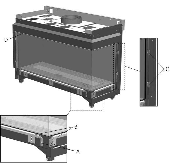
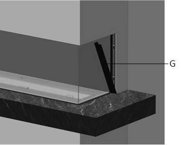
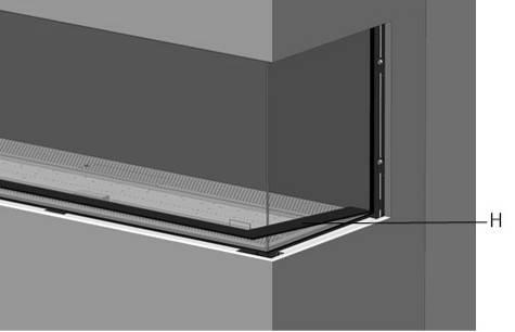
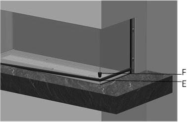
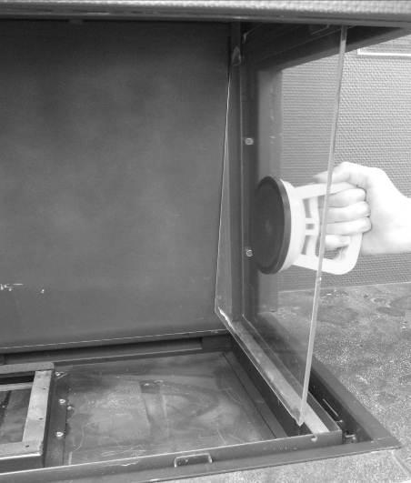
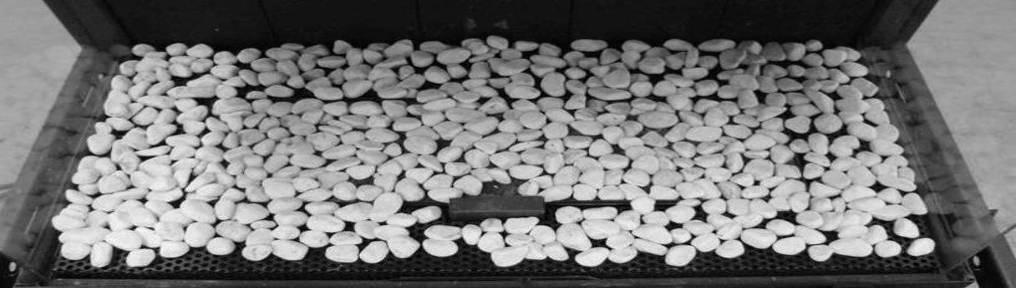
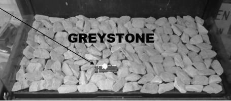
9 These mounting materials are exclusively intended for use on walls constructed of brick or concrete. For walls built of other materials, such as hollow bricks, consult a professional expert. 4.5 Installing the Flue materials When penetrating a wall or ceiling the opening must be at least 5mm larger than the diameter of the discharge material. Horizontal sections should be installed with a slope towards the fire (3 degrees). Build the system from the fire. If this is not possible you can make use of an extendable adapter section. For truing up the exhaust system use the ½ meter pipe, which can be shortened and ensure that the inner pipe is always 2cm longer than the outer pipe. Parts, which are shortened, must be secured with a self-tapping screw Wall and roof terminals can also be cut. Do not insulate but ventilate built-in flue material. (approx. 100cm2). 4.6 Constructing the false chimney If possible, carry out a performance test on the fire before finally finishing the installation Minimum false chimney size and distance to combustible materials Construct the false chimney of non-combustible material in combination with metal profiles or of masonry/concrete blocks. Always use a lintel or reinforcing bars while bricking the outlet. They should not be placed directly on the fire Ventilation The ventilation must comply with the applicable local standards. Correct ventilation prevents a too high temperature of the gas regulator block and its electronics and also limits the temperature of the convection air. Therefore plan for outlet of grills and a ventilating control hatch with a minimum free passage of 200cm 2 per grid or a similar alternative. Place above the grates a screen plate made of noncombustible material. ( Fig. 1.2A) Installation and finishing For installation and finishing the following points are of interest: A = Fixing points (Fig. 2.2). B = Mouldings (Fig. 2.2). C = Spacer (Fig. 2.5) D, F and H (Fig. 2.2, 2.3 and 2.5). Please note: Ensure that the fire is not load-bearing with regard to the false chimney breast. (See the dimensional drawing Chapter 16.1). Pay special attention to the following points: 1. Check during work if the glass can be inserted and removed. 2. Check during work if the strips T (Fig. 3.2) or Q (Fig. 3.3) match Method 1 (Fig. 2.1a) Build the false chimney breast against the fixing points A, the mouldings B and the build-in frame D (Fig. 2.2). The installation must always allow for installing and removing the glass! Take into account the thickness of the finish! Mouldings B has to be in line (F Fig. 2.3) with the top of the glass slot H.(Fig. 2.5) Do not use moulding B as a supporting structure (fig. 2.5) Remove the fixing points (A) on the side wall before the outlet wall is finally finished! (Fig. 2.4) Method 2 (Fig. 2.1b) Process see Chapter Method 3 (Fig. 2.1c) Remove the moulding B (Fig. 2.2). To ensure the air-tightness of the unit the screws must be replaced. The base X (Fig. 2.5) must be 2mm clear of the spacer C (Fig. 2.5) and 4mm above the glass slot H of the unit (Fig. 2.5). This will allow the Strip Q (Fig. 3.3) to be on the same level as the base Mounting the Solid cover strips (Fig. 3.1, 3.2 and 3.3) First, place the bottom strip (T or Q) Then place the left and right strips (S) (these are fixed by the adjustable magnetic snappers) 8 < < < <
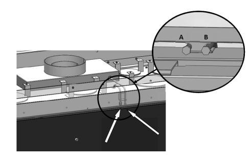
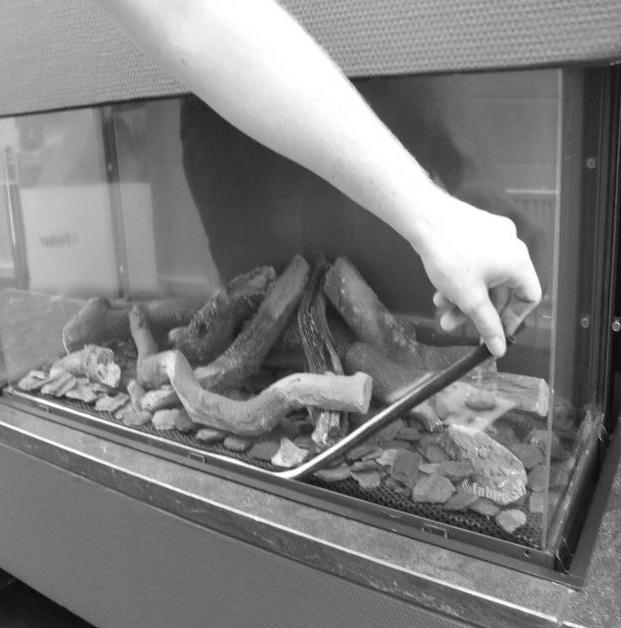
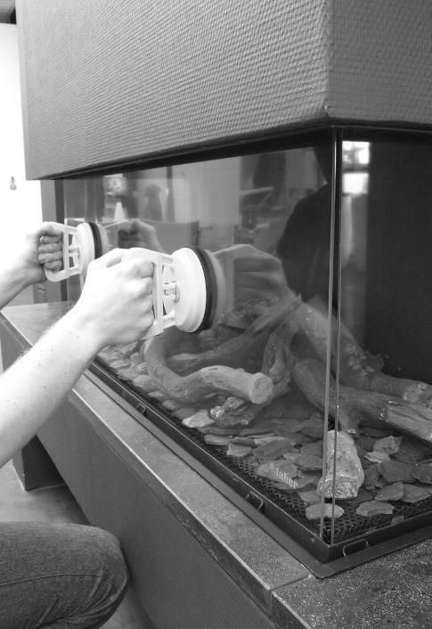
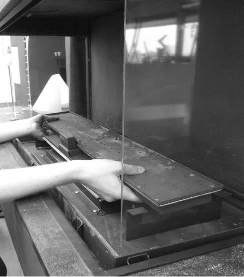
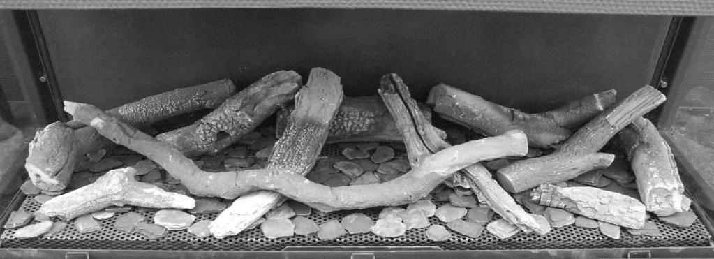
10 Remove the bottom strip (Q) using the supplied magnetic knob (R, Fig. 3.3). 5 Removing the glass 5.1 removing the front glass Remove the solid covers trips see Chapter Place the suction cups on the glass. Draw the sealing cord from the slot. (Fig.4.1). Slide the glass to the top so that the bottom is released from the slot. Now pull the glass out and gradually down. (Fig. 4.2). 5.2 removing the glass from the side It is not necessary to take out the glass on the side for placing the log set or for maintenance. First remove the front glass. Remove the log set, bottom plate and burner. (Fig. 4.3) Place the suction cups on the glass Remove the sealing cord from the slot. Remove the top of the glass gradually forward and up from the fire (Fig.4.4) Please note Replace the glass in reverse order. Clean all fingerprints from the glass, otherwise they will burn in once the fire is used. 6 Placing the decoration material It is not permitted to use other or to add more material in the combustion chamber. Keep the pilot light always free of decoration material! Do not place all decoration material at one time on the burner; the fabric parts can block it. 6.1 Log set Place some of the chips on the burner and on the bottom. Place the logs as specified. (Fig.5.1 or the included log set card) Divide the rest of the chips on the burner and on the bottom. Prevent a thick layer on the burner; this adversely affects the flame pattern. 6.2 Glow wire The glow wire gives a decorative glow effect. Pull the wool well apart and place tufts in different places on the burner. Please note: Do not use the glow wire near the pilot flame! This can cause a short circuit in the ignition system! 6.3 Pebbles or Grey stone Place the pebbles or grey stones on the burner and on the bottom. (Fig. 5.2 and 5.3 or the included log set card). Prevent a double layer; this adversely affects the flame pattern. Replace the glass and check the flame pattern. Start the fire as described in the user manual. Check if the flame distribution is good. Move the chips if necessary, until a good flame distribution is achieved. 7 Checking the installation 7.1 Checking the main burner ignition, pilot flame Ignite the fire as described in the user manual. Check that the pilot flame is well above the main burner and not covered by chips. Check the ignition of the main burner on full and small setting. (ignition must be smooth and quiet). 7.2 Checking for gas leaks Check with a gas leak finder or spray all connections and pipes for gas leakage. 7.3 Checking the burner pressure and primary pressure Check that the burner pressure and primary pressure match the information listed in the manual, Chapter 14 Technical specifications. Measuring the primary pressure: Close the shutoff valve. Turn measuring nipple B (Fig. 1.6) some turns open and connect a measuring hose to the gas regulator. 9 < < < <
11 Take this measurement at highest setting of the fire and when the fire is set to pilot light. Do not connect the unit if the pressure is too high. Measuring the burner pressure: Check the burner pressure only with proper primary pressure. Turn measuring nipple A (Fig. 1.6) some turns open and connect a measuring hose to the gas regulator. The pressure must correspond to the value indicated in the technical specifications of this manual. In case of deviation contact the manufacturer. Please note: Close all pressure measuring nipples and check for gas leakage. 7.4 Checking the flame image Let the fire burn for at least 20 minutes at highest setting and check the flame for: 1. Flame distribution 2. Colour of the flames If one or both points are not acceptable then check: The log set layout and/or the amount of chips on the burner. The pipe connections for leaks (in case of blue flames). Whether the correct Restrictor is fitted. The outlet. o Wall terminal right side up o Roof terminal on the right position o If the maximum horizontal flue lengths is not exceeded. 7.5 Flue gas analyzer If you are in possession of a CO/CO2 flue gas analyzer, then it is possible to check the supply air and the combustion gases. There are two measuring pipes at the front of the fire between the mounting frame and the glass (Fig. 1.7 A and B). The ratio CO2 and CO must not be greater than 1:100 Example: CO2 is 4% and CO is 400ppm, measured at the highest point If the ratio is greater than 1:100 or exhaust gases are measured in the supply air, then also check above points. 8 Instructions for client Recommend that the unit should be checked annually by a qualified specialist to ensure the safe use and to guarantee a long service life. Give advice and instructions on care and cleaning of the glass. Highlight the danger of burnt-in fingerprints. Instruct the customer on the operation of the unit and the remote control, including replacing the batteries and setting the receiver. Handover to customer: o Installation instructions o User manual o ITC operating instructions o Log set instruction card o Suction Cups o Magnetic snapper 9 Annual maintenance 9.1 Checking and cleaning: Check and clean if necessary after verification: o The pilot light o The burner; for LPG flat burner the ceramic burner top. o The combustion chamber o The glass o The ceramic logs for breakages. o The flue system. Replace, if necessary: o Chips/Embers/ Glow wire 9.2 Cleaning the glass Most deposits can be removed with a dry cloth. Clean the glass with a ceramic hob cleaner. Please note: Avoid fingerprints on the glass. These are no longer removable after they are burnt in! Now carry out the checks described in Chapter 7 Checking after installation. 10 < < < <
12 10 Conversion to other gas type The conversion to a different gas type may only be performed by a qualified installer/dealer Conversion from natural gas to propane (or vice versa) This can only be done by replacing the burner. To do so, please contact your dealer. Specify with your order always the type and serial number of the device. Total Vertical Height (TVH) TVH is the difference in height measured from the top of the fire to the outlet; it can be measured or determined from the building plan. For clarification see the TVH indication in the drawings. (Fig. 12.1, 12.2 and 12.3: TVH) Total Horizontal Length (THL) THL is the Total Horizontal Length and consists of elbows and pipes which are entirely in the horizontal plane. Elbows I, K and Q and the elements H, J, L, M, P and R (Fig and 12.3). Horizontal length The horizontal length consists of the elements H, J, L, M, P and R (Fig end 12.3). Elbows 90 in the horizontal plane Horizontal bends are bends which are entirely in the horizontal plane (Fig. 12.1, 12.2 and 12.3 I, K and Q). 11 Flue calculation A simple way to calculate whether the exhaust configuration is possible in combination with your fire, use the free Faber Flue App and download from: INTERNET: BlackBerry, Android, PC (with Google Chrome browser) APP store: iphone, ipad and Mac. Google Play: Android smartphones and Android tablets. Alternatively use the exhaust calculation table. (see chapter 13). The alternatives of outlet lengths and any restrictors are set out in the restrictor table. In the table we work with Start Length (STL) Total Vertical Height (TVH) and Total Horizontal Length (THL). Start Length (STL) This is the first part that is placed on the fire and represents a certain value (Fig. 12.1, 12.2 and 12.3 A, N, F). This value is in the top row of the table (see table). Bends 45 or 30 in the horizontal plane Horizontal bends are bends which are entirely in the horizontal plane Bends Elbows 90 vertical to horizontal plane These are 90 elbows, which proceed from horizontal to vertical (Fig and 12.3 G, O and S) Bends 45 or 30 vertical to horizontal plane These are 30 or 45 bends with a vertical offset of less than 45 (Fig.12.1 B and D). Pipes under a tilt angle: These are pipes which are vertically ascending at an angle of 30 or 45. (Fig C). Fill in only in combination with at least 2 x 30 or 45 bends in the vertical part. Table: See the table at the right vertical (TVH) and horizontal length (THL). For x and if the values are outside the table, then the combination is not allowed. Only then adjust the TVH or THL. If a value is indicated, check that the calculated STL value is not lower than indicated in the table. In this case STL must be adjusted. The found value indicates the width of the restrictor ( 0 means no restrictor). Standard is a restrictor of 30mm installed. (Fig.1.8). 11 < < < <
13 STL 0, Table for pipe diameter 150/100mm Startlength (STL) Vertical (TVH) and Horizontal (THL) THL 12 < < < <
14 TVH TVH THL 0 x x x x x x x x x x x 0,5 x x x x x x x x x x x x x x x x x x x x 1,5 0,2 0,2 x x x x x x x x x 2 0,2 30,2 0,2 x x x x x x x x 3 30,2 40,2 0,2 x x x x x x x x 4 40,2 40,2 30,2 0,2 x x x x x x x 5 45,2 40,2 40,2 30,2 x x x x x x x 6 45,2 45,2 40,2 40,2 x x x x x x x 7 50,2 45,2 45,2 40,2 x x x x x x x 8 50,2 50,2 45,2 45,2 x x x x x x x 9 50,2 50,2 50,2 45,2 x x x x x x x 10 60,2 50,2 50,2 50,2 x x x x x x x 11 60,2 60,2 50,2 50,2 x x x x x x x 12 70,2 70,2 60,2 50,2 x x x x x x x 13 70,2 70,2 70,2 60,2 x x x x x x x 14 80,2 70,2 70,2 70,2 x x x x x x x 15 80,2 80,2 80,2 70,2 x x x x x x x 16 80,2 80,2 80,2 80,2 x x x x x x x 17 80,2 80,2 80,2 80,2 x x x x x x x 18 80,2 80,2 80,2 80,2 x x x x x x x 19 80,2 80,2 80,2 80,2 x x x x x x x 20 80,2 80,2 80,2 80,2 x x x x x x x 21 80,2 80,2 80,2 80,2 x x x x x x x 22 80,2 80,2 80,2 80,2 x x x x x x x 23 80,2 80,2 80,2 80,2 x x x x x x x 24 80,2 80,2 80,2 80,2 x x x x x x x 25 80,2 80,2 80,2 80,2 x x x x x x x 26 80,2 80,2 80,2 80,2 x x x x x x x 27 80,2 80,2 80,2 80,2 x x x x x x x 28 80,2 80,2 80,2 x x x x x x x x 29 80,2 80,2 x x x x x x x x x x x x x x x x x x x 13 < < < <
15 11.2 Tabel voor pijp diameter 130/200mm STL TVH Startlengte (STL) Verticaal (TVH) en Horizontaal (THL) STL 0,1 0,2 0,5 0, TVH THL 0 x x x x x x x x x x x 0,5 x 30 x x x x x x x x x x x 1,5 40,4 50,4 40,4 30,4 0,4 0,4 0,4 0,4 0,4 x x 2 50,4 60,4 50,4 40,4 30,4 0,4 0,4 0,4 0,4 x x 3 60,4 65,4 60,4 50,4 40,4 30,4 0,4 0,4 0,4 x x 4 65,4 70,4 65,4 60,4 50,4 40,4 30,4 0,4 0,4 x x 5 70,4 70,4 70,4 65,4 60,4 50,4 40,4 30,4 0,4 x x 6 70,4 70,4 70,4 70,4 65,4 60,4 50,4 40,4 30,4 x x 7 70,4 80,4 70,4 70,4 70,4 65,4 60,4 50,4 40,4 x x 8 80,4 80,4 80,4 70,4 70,4 70,4 65,4 60,4 50,4 x x 9 80,4 80,4 80,4 80,4 70,4 70,4 70,4 65,4 60,4 x x 10 80,4 80,4 80,4 80,4 80,4 70,4 70,4 70,4 65,4 x x 11 80,4 80,4 80,4 80,4 80,4 80,4 70,4 70,4 70,4 x x 12 80,4 80,4 80,4 80,4 80,4 80,4 80,4 70,4 70,4 x x 13 85,4 80,4 80,4 80,4 80,4 80,4 80,4 80,4 70,4 x x 14 85,4 85,4 80,4 80,4 80,4 80,4 80,4 80,4 80,4 x x 15 85,4 85,4 85,4 80,4 80,4 80,4 80,4 80,4 80,4 x x 16 85,4 85,4 85,4 85,4 80,4 80,4 80,4 80,4 80,4 x x 17 85,4 85,4 85,4 85,4 85,4 80,4 80,4 80,4 80,4 x x 18 85,4 85,4 85,4 85,4 85,4 80,4 80,4 80,4 80,4 x x 19 85,4 85,4 85,4 85,4 85,4 85,4 80,4 80,4 80,4 x x 20 85,4 85,4 85,4 85,4 85,4 85,4 85,4 80,4 80,4 x x 21 85,4 85,4 85,4 85,4 85,4 85,4 85,4 85,4 80,4 x x 22 85,4 85,4 85,4 85,4 85,4 85,4 85,4 85,4 85,4 x x 23 85,4 85,4 85,4 85,4 85,4 85,4 85,4 85,4 x x x 24 85,4 85,4 85,4 85,4 85,4 85,4 85,4 x x x x 25 85,4 85,4 85,4 85,4 85,4 85,4 x x x x x 26 85,4 85,4 85,4 85,4 85,4 x x x x x x 27 85,4 85,4 85,4 85,4 x x x x x x x 28 85,4 85,4 85,4 x x x x x x x x 29 85,4 85,4 x x x x x x x x x 30 85,4 x x x x x x x x x x THL 14 < < < <

16 12 Example fig fig.12.2 fig < < < <

17 13 Calculation sheet 16 < < < <

18 17 < < < <
19 14 Technical data Gascat. II2H3+ II2H3+ II2H3+ Type appliance C11 C31 C11 C31 C11 C31 Reference gas G20 G30 G31 Input Nett kw ,5 Efficiency class NOx class inlet-pressure mbar Gas rate at 15ºC and 1013 mbar l/h Gas rate at 15ºC and 1013 mbar gr/h Burner pressure at full mark mbar Injector main burner mm 2x St510 (7x0,83) 2x St180 (7x0,5) 2x St180 (7x0,5) Reduced input restraint mm 2,10 1,60 1,60 Pilot assembly SIT145 SIT145 SIT145 Code Nr.36 Nr.23 Nr.23 Diameter inlet / outlet mm 200/ / /130 Gas control valve GV60 GV60 GV60 Gas connection 3/8 3/8 3/8 Electrical connection V Batteries receiver V 4x AA (1,5V) 4x AA (1,5V) 4x AA (1,5V) Batteries sender V < < < <
20 15 Terminal position Please note: These rules apply only for the proper functioning of the unit, for ventilation and environmental protection you need to comply with the applicable rules as defined in the building regulations. Short roof terminal Only for existing Chimney connection Extension pipe over roof Location Distance mm D Under a gutter 500 E Under a roof edge 500 F Under a carport or balcony 500 G Vertical downpipe 300 H Inside and outside corners 500 J From wall surface to a wall outlet 1000 K Two gable outlets against over each other 1000 L Distance between two roof outlets 450 M Two roof outlets above each other on a pitched roof 1000 N Two gable outlets next to each other < < < <
21 16 Dimensional drawings 16.1 Duet Premium M left 20 < < < <
22 16.2 Duet Premium M right 21 < < < <
23 Ventilation grid and control door 22 < < < <


24
Duet Premium M Duet Premium M ENG
 Duet Premium M 40011422-1441 Duet Premium M ENG 1.1 1.2 1.3 1.4 1.5 1.6 1.7 1.8 1 < < < < 2.1 a 2.1 b 2.1 c A C 2.2 2 < < < < F F 2.3 X H X C 2.4 2.5 S T 3.1 3.2 R Q 3.3 3 < < < < 4.1 4.2 4.3 4.4 4 <
Relaxed Premium M Relaxed Premium M ENG
 Relaxed Premium M 40010959 1440 Relaxed Premium M ENG 3 alternative finishes. 1.1a 1.1b 1.1c 1 < < < < 1.2 1.3 7 1.4 2 < < < < 1.5 1.6 B 1.9 3 < < < < 2.1 2.2 2.3 3.1 3.2 3.3 3.4 4 < < < < 3.5 4.1 4.2
Solution Installation guide
 Solution 40011444-1327 ENG Installation guide ENG 1-1 1-2 1-3 1.4 1 < < < < 2.1 2-3 2-4 2 < < < < 3-1 3.2 3-3 3.5 3.6 3 < < < < 4-1 A 4-2 4-3 4 < < < < Dimensions Terminal position Distance (For good working
Duet XL /0929. Installation guide
 Duet XL 40010749/0929 ENG Installation guide ENG 1.1 1.2 1.3 1.4 1.5 A 1.6 1.7 1 < < < < B A 2.1 2.2 2.3 2.4 2 < < < < 2.5 2.6 2.7 2.8 3 < < < < 3.1 F F 3.2 3.3 4 < < < < Table of contents 1 Introduction...
Respect OC Installation manual
 Respect OC 40011335-1235 ENG Installation manual ENG 1.1 1.2 A 1.3 1.4 A A 2.1 2.2 2.3 1 < < < < 2.4 2.5 B C A B A 2.6 2 < < < < 3.1 3.2 3.3 3.4 3.5 3.6 3 < < < < A B 3.7 4 < < < < L A A 4.1 A A 4.2 A
Clear Installation guide
 Clear 40010631-0938 ENG Installation guide ENG 1.1 1.2 1.3 A 1.4 1.5 1 < < < < A B 2.1 2.2 2.3 C 2.4 2.5 2 < < < < 3.1 3.2 3-3 3 < < < < Inhoudsopgave 1 Introduction... 6 2 Safety instructions... 6 3 Installation
Fyn Installation guide
 Fyn 450 400100929-1114 ENG Installation guide ENG 1.1 1.2 A B 1.3 1.4 1 < < < < 2.1 2.2 2.3 3.1 3.2 2 < < < < 4.1 4.2 4.3 4.4 3 < < < < Table of contents 1 Introduction... 6 2 Safety instructions... 6
Fyn Installation guide
 Fyn 600 4001131-1123 ENG Installation guide ENG 1.1 1.2 A B 1.3 1.4 1 < < < < 2.1 2.2 2.3 2.4 3.1 3.2 2 < < < < 4.1 4.2 4.3 4.4 3 < < < < 1 Introduction The appliance can only be installed by a competent
Vaska Logburner. voorbeeld Installation guide
 Vaska ogburner voorbeeld 40010627-2103 ENG Installation guide ENG 1.1 1.2 1.3 1.4 1.5 1 < < < < 1 Introduction The appliance can only be installed by a competent person in accordance with the Gas Safety.
Hestia Installation Guide
 Hestia 40010610-0746 UK Installation Guide Content 1.1 1.2 1.3 1.4 A B C D 1.5 1.6 1 < < < < Hestia with Wirdum Surround 2.1 2.2 2.3 2.4 2.5 2.6 > > > > 2 Hestia with Jellum Surround 3.1 3.2 3.3 3.4 3.5
Installation manual (EN/UK) Modore 185
 Modore 185") (EN/UK) Modore 185 Warning: The combustion chamber of this stove should only be opened and serviced by a registered gas installer. Leave these instructions as manual with the device Table of content Installation
(EN/UK) Modore 185 Warning: The combustion chamber of this stove should only be opened and serviced by a registered gas installer. Leave these instructions as manual with the device Table of content Installation
PowerVent. Installation manual (GB) English. Store this document in a safe place UK
 English. Store this document in a safe place UK") PowerVent Installation manual (GB) Store this document in a safe place 959.034.03.UK GB Contents Blz Foreword 3 1. Introduction 3 2. CE declaration 4 3. SAFETY 4 3.1 General 4 3.2 Regulations 4 3.3 Precautions
PowerVent Installation manual (GB) Store this document in a safe place 959.034.03.UK GB Contents Blz Foreword 3 1. Introduction 3 2. CE declaration 4 3. SAFETY 4 3.1 General 4 3.2 Regulations 4 3.3 Precautions
VASKA C11. gas -fireplace installation guide
 VASKA C11 gas -fireplace installation guide Saturnus 8 NL-8448 CC Heerenveen Postbus 219 NL-8440 AE Heerenveen T. +31(0)513 656500 F. +31(0)513 656501 40 010 459 01 51 DESCRIPTION OF THE FIREPLACE CONTENTS
Installation manual (EN/UK) Lucius 140 MKП
 Lucius 140 MKП") (EN/UK) Lucius 140 MKП Warning: The combustion chamber of this stove should only be opened and serviced by a registered gas installer. Leave these instructions as manual with the device Table of content
(EN/UK) Lucius 140 MKП Warning: The combustion chamber of this stove should only be opened and serviced by a registered gas installer. Leave these instructions as manual with the device Table of content
Torch framed Installation Guide
 Torch framed 40010567-0602 Installation Guide 1 2 3 4 1 < < < < 5 6 7 > > > > 2 Content 1 Introduction... 1 2 Safety Instructions... 2 3 Installation requirements... 3 3.1 Rear surface construction...
VASKA B11. gas -fireplace installation guide
 VASKA B11 gas -fireplace installation guide Saturnus 8 NL-8448 CC Heerenveen Postbus 219 NL-8440 AE Heerenveen T. +31(0)513 656500 F. +31(0)513 656501 40 010 446 01 51 DESCRIPTION OF THE FIREPLACE CONTENTS
PowerVent. Installation manual (GB) English. Store this document in a safe place UK
 English. Store this document in a safe place UK") PowerVent Installation manual (GB) Store this document in a safe place 959.078.00.UK GB Contents page Foreword 3 1. Introduction 3 2. CE declaration 4 3. SAFETY 4 3.1 General 4 3.2 Regulations 4 3.3 Precautions
PowerVent Installation manual (GB) Store this document in a safe place 959.078.00.UK GB Contents page Foreword 3 1. Introduction 3 2. CE declaration 4 3. SAFETY 4 3.1 General 4 3.2 Regulations 4 3.3 Precautions
Decorative Fuel Effect Appliances
 Decorative Fuel Effect Appliances Technical Manual User and Installation Instructions for CUBB22US Available in Natural Gas. 1 Contents Section Pages 1 Unpacking 3 2 Installation Parameters 4 3 Installation
UK/IRL. Saturnus 8 NL CC Heerenveen. P.O. Box 219 NL AE Heerenveen T. +31(0) F. +31(0) < < < <
 F. +31(0) < < < <") Saturnus 8 NL - 8448 CC Heerenveen P.O. Box 219 NL - 8440 AE Heerenveen T. +31(0)513 656500 F. +31(0)513 656501 56 < < < < PURE (BF80S) SILENCE FEELING SENSE WHISPER SPECTRA NOVA CADRA NOVA MISTY Room-sealed
Saturnus 8 NL - 8448 CC Heerenveen P.O. Box 219 NL - 8440 AE Heerenveen T. +31(0)513 656500 F. +31(0)513 656501 56 < < < < PURE (BF80S) SILENCE FEELING SENSE WHISPER SPECTRA NOVA CADRA NOVA MISTY Room-sealed
Evolve 951 & Product specification pages
 951 & 1250 Product specification pages SUPPORTING ASTHMA CARE Evolve Specification Evolve 951 Evolve 1250 Inbuilt power flued convection fan heater with electronic temperature control, timers, and remote.
LUNA 850 V GOLD GAS INSTRUCTION FOR INSTALLATION AND USE. Passion for fire
 LUNA 850 V GOLD GAS INSTRUCTION FOR INSTALLATION AND USE Passion for fire SUMMARY 1. GENERAL REMARKS...3 2. CONNECTION...3 3. SPECIFICATION SHEET...4 4. ASSEMBLY OF THE CHIMNEY...5-7 5. ELECTRICAL CONNECTION...8
VIEW BELL SMALL 3 CF/LF
 INSTALLATION INSTRUCTIONS & MANUAL FOR MAINTENANCE VIEW BELL SMALL 3 CF/LF Gas fi res with closed combustion system Bellfi res wishes you many cosy evenings with your new Bellfi res gas fi re This document
INSTALLATION INSTRUCTIONS & MANUAL FOR MAINTENANCE DERBY LARGE 3 CF/LF. Gas fi re with closed combustion system
 INSTALLATION INSTRUCTIONS & MANUAL FOR MAINTENANCE DERBY LARGE 3 CF/LF Gas fi re with closed combustion system Bellfi res wishes you many cosy evenings with your new Bellfi res gas fi re This document
Installation Manual EF5000 AUS & NZ
 Installation Manual EF5000 AUS & NZ This manual is ONLY for fires with a serial No. from 80600 to 80999. Important: The appliance shall be installed in accordance with; Local gas fitting regulations Municipal
LUNA H GOLD GAS INSTRUCTION FOR INSTALLATION AND USE
 LUNA 700-1000-1150-1300-1600-1900 H GOLD GAS INSTRUCTION FOR INSTALLATION AND USE UK 11-2012 1 V E R Y I M P O R T A N T I N S T A L L A T I O N I N S T R U C T I O N S F O R T H E M - D E S I G N G A
PowerVent Installation manual. English. Store this document in a safe place EN
 PowerVent - 02 Installation manual Store this document in a safe place 959.114.01.EN en Contents Page Foreword 3 1. Introduction 3 2. CE declaration 4 3. SAFETY 4 3.1 General 4 3.2 Regulations 4 3.3 Precautions
Installation instruction
 Installation instruction Ci50 www.contura.eu 82 CERTIFICATE Declaration of performance according to Regulation (EU) 305/2011 No. Ci50-CPR-150821-SE-2 PRODUCT Product type Type designation Manufacturing
Operating instructions for the DA 8-2 Extractor
 Operating instructions for the DA 8-2 Extractor ]ö M.-Nr. 03 997 810 Description of the appliance Description of the appliance 1 2 6 5 4 3 2 Description of the appliance Description of the appliance The
ROOM DIVIDER LARGE 3 CF/LF ROOM DIVIDER LARGE 3 L/R CF/LF
 INSTALLATION INSTRUCTIONS & MANUAL FOR MAINTENANCE ROOM DIVIDER LARGE 3 CF/LF ROOM DIVIDER LARGE 3 L/R CF/LF Gas fi res with closed combustion system Bellfi res wishes you many cosy evenings with your
VASKA C11. gas-fireplace user manual. Saturnus 8 NL-8448 CC Heerenveen Postbus 219 NL-8440 AE Heerenveen T. +31(0) F.
 F.") VASKA C11 gas-fireplace user manual Saturnus 8 NL-8448 CC Heerenveen Postbus 219 NL-8440 AE Heerenveen T. +31(0)513 656500 F. +31(0)513 656501 40 010 458 01.51 DESCRIPTION OF THE FIREPLACE CONTENTS 1 2
VASKA C11 gas-fireplace user manual Saturnus 8 NL-8448 CC Heerenveen Postbus 219 NL-8440 AE Heerenveen T. +31(0)513 656500 F. +31(0)513 656501 40 010 458 01.51 DESCRIPTION OF THE FIREPLACE CONTENTS 1 2
C D INSTALLATION 16 INSTALLER GENERAL INFORMATION
 INSTALLATION GENERAL INFORMATION This appliance is sealed from the surrounding environment in which it is installed and consequently combustion air is only aspired from outside! - When installing, NEVER
Dovre 250 Cast Iron Gas Stove
 Dovre 50 Cast Iron Gas Stove NATURAL GAS AND LPG INSTALLATION, SERVICING AND USER INSTRUCTIONS THIS PRODUCT IS FOR USE ONLY IN GREAT BRITAIN AND IRELAND These instructions are to be left with the customer,
CRYSTAL FIRES. Inset Conventional Flue Fire. (BOSTON/MIAMI) Cf1 and MANHATTAN USER INSTALLATION AND SERVICING INSTRUCTIONS
 Cf1 and MANHATTAN USER INSTALLATION AND SERVICING INSTRUCTIONS") CRYSTAL FIRES (BOSTON/MIAMI) Cf1 and MANHATTAN Inset Conventional Flue Fire USER INSTALLATION AND SERVICING INSTRUCTIONS FOR USE WITH NATURAL GAS G20 @ 20 mbar For use in GB and IE CE THESE INSTRUCTIONS
CRYSTAL FIRES (BOSTON/MIAMI) Cf1 and MANHATTAN Inset Conventional Flue Fire USER INSTALLATION AND SERVICING INSTRUCTIONS FOR USE WITH NATURAL GAS G20 @ 20 mbar For use in GB and IE CE THESE INSTRUCTIONS
IDE 20 / IDE 30 / IDE 50 IDE 60 / IDE 80
 IDE 20 / IDE 30 / IDE 50 IDE 60 / IDE 80 EN OPERATING MANUAL OIL HEATER TRT-BA-IDE20-30-50-60-80-TC-001-EN Table of contents Information on the use of this manual... 1 Scope of delivery... 1 General safety...
MODELS LFP4218/LFP6018 TOP VENT GAS FIREPLACE
 MODELS LFP4218/LFP6018 TOP VENT GAS FIREPLACE PFS APPROVED FOR NATURAL GAS OR PROPANE GAS Z21.50-2014 If your plans do not allow for the venting system as outlined previously in the installing chimney/vent
USE & MAINTENANCE INSTRUCTIONS FOR NU-FLAME EVOLUTION PLUS GAS EFFECT FIRES (NATURAL GAS & LPG) FOR DECORATIVE PURPOSES ONLY
 FOR DECORATIVE PURPOSES ONLY") Unit 4, Kimpton Trade & Business Centre Minden Road, Sutton, Surrey SM3 9PF Tel: 020 8254 6802 IMPORTANT NOTE Simulated coals, simulated pebbles, simulated logs, simulated driftwood or crushed rock manufactured
Unit 4, Kimpton Trade & Business Centre Minden Road, Sutton, Surrey SM3 9PF Tel: 020 8254 6802 IMPORTANT NOTE Simulated coals, simulated pebbles, simulated logs, simulated driftwood or crushed rock manufactured
Installation Manual EF5000 NZ
 Installation Manual EF5000 NZ Important: The appliance shall be installed in accordance with; Local gas fitting regulations Municipal building codes AS/NZS 5601.1.1:2010 Gas Installation Any other relevant
USE & MAINTENANCE INSTRUCTIONS FOR NU-FLAME FIREBOXX SYSTEM (NATURAL GAS & LPG) FITTED WITH EVOLUTION PLUS BURNER. FOR DECORATIVE PURPOSES ONLY
 FITTED WITH EVOLUTION PLUS BURNER. FOR DECORATIVE PURPOSES ONLY") Unit 4, Kimpton Trade & Business Centre Minden Road, Sutton, Surrey, SM3 9PF Tel: 020 8254 6802 IMPORTANT NOTE Simulated crushed rock, simulated pebbles, simulated logs, or simulated driftwood, manufactured
Unit 4, Kimpton Trade & Business Centre Minden Road, Sutton, Surrey, SM3 9PF Tel: 020 8254 6802 IMPORTANT NOTE Simulated crushed rock, simulated pebbles, simulated logs, or simulated driftwood, manufactured
Installation and service must be provided by a qualified installer, service agency or the gas supplier.
 INSTALLATION AND OPERATION GUIDE FOR OLDE WORLD BASKET Vented Decorative Appliance For all models tested through PFS Corporation, to ANSI Z21.60-2003/CGA 2.26-2003, Decorative Appliance for Installation
Installation and user manual CLOSED WOOD FIRES DON T COMPROMISE.
 Installation and user manual EN CLOSED WOOD FIRES DON T COMPROMISE. Product Product group Application Models Kalfire W Wood burning fireplaces with lifting door Open and closed Kalfire W45/48F Kalfire
TC MODULE (FFD) (with Gas Hob)
 (with Gas Hob)") TC MODULE (FFD) (with Gas Hob) Installation Instructions REMEMBER: when replacing a part on this appliance, use only spare parts that you can be assured conform to the safety and performance specification
TC MODULE (FFD) (with Gas Hob) Installation Instructions REMEMBER: when replacing a part on this appliance, use only spare parts that you can be assured conform to the safety and performance specification
INSTRUCTIONS MANUAL FOR USE AND MAINTENANCE
 INSTRUCTIONS MANUAL FOR USE AND MAINTENANCE Carbel models: C-60 Plus C-70 Plus C-80 Plus C-100 Plus C-70 Plus Double-sided C-80 Plus Double-sided C-100 Plus Double-sided CARBEL C/ Ciudad de Cartagena,
GB IE. VALOR BOLERO (MODEL BR626) Inset Decorative Fuel Effect Gas Fires. For
 Inset Decorative Fuel Effect Gas Fires. For") O W N E R G U I D E For VALOR BOLERO (MODEL BR626) Inset Decorative Fuel Effect Gas Fires GB IE This Owner Guide is intended to help you care for your Valor gas fire. Please read carefully before using
O W N E R G U I D E For VALOR BOLERO (MODEL BR626) Inset Decorative Fuel Effect Gas Fires GB IE This Owner Guide is intended to help you care for your Valor gas fire. Please read carefully before using
Installation instruction
 Installation instruction C i40 www.contura.eu 82 CERTIFICATE Declaration of performance according to Regulation (EU) 305/2011 No. Ci40-CPR-130912-SE-2 PRODUCT Product type Type designation Manufacturing
SIERRA RADIANT HEAT MAJESTIC OAK VENTED GAS LOG KIT INSTALLATION AND OPERATING INSTRUCTIONS
 SIERRA RADIANT HEAT MAJESTIC OAK VENTED GAS LOG KIT INSTALLATION AND OPERATING INSTRUCTIONS WARNING: If the information in this manual is not followed exactly, a fire or explosion may result causing property
INSTALLATION & USERS INSTRUCTIONS. FOR USE WITH NATURAL GAS 20 mbar For use in GB and IE
 1 valentine s buildings Bechers drive Aintree racecourse Business Park L9 5ay CF1 L GAS APPLIANCE INSET CONVENTIONAL FLUED GAS FIRE INSTALLATION & USERS INSTRUCTIONS FOR USE WITH NATURAL GAS G20 @ 20 mbar
MODEL 466 Radiant / Convector Gas Fire Black Beauty
 O W N E R G U I D E MODEL 466 Radiant / Convector Gas Fire Black Beauty This Owner Guide is intended to help you care for your Valor gas fire. Please read carefully before using your gas fire and keep
LUNA 850 V / 550 V GOLD GAS LUNA 850 DV / 550 DV GOLD GAS
 LUNA 850 V / 550 V GOLD GAS LUNA 850 DV / 550 DV GOLD GAS INSTRUCTION FOR INSTALLATION AND USE English 09-2011 Passion for fire V E R Y I M P O R T A N T I N S T A L L A T I O N I N S T R U C T I O N S
COAL EFFECT BALANCED FLUE GAS FIRE
 Raglan COAL EFFECT BALANCED FLUE GAS FIRE Installation and Maintenance Instructions Hand these instructions to the user Model No. KBFC**MN for use on Natural Gas (G20) at a supply pressure of 20 mbar in
USER S INFORMATION MANUAL
 USER S INFORMATION MANUAL HOT WATER HEATING BOILERS DOMESTIC WATER HEATERS 150,000-300,000 Btu/hr MODELS EB-EWU-02 IMPORTANT INSTALLER - AFFIX INSTALLATION MANUAL ADJACENT TO THE BOILER CONSUMER - RETAIN
Installation & User Instructions: Model: e600s e600gf e700s e1000s e1000gf e1030gf/2/3 e1500gf/2/3
 Installation & User Instructions: Model: e600s e600gf e700s e1000s e1000gf e1030gf/2/3 e1500gf/2/3 Once installed, the installer should take the appropriate steps To ensure that the user understands how
USE & MAINTENANCE INSTRUCTIONS FOR CHESNEYS ALCHEMY EVOLUTION PLUS GAS FIRES (NATURAL GAS ONLY) FOR DECORATIVE PURPOSES ONLY
 FOR DECORATIVE PURPOSES ONLY") CHESNEYS ALCHEMY EVOLUTION PLUS GAS FIRE by IMPORTANT NOTE Simulated coals, or simulated logs, together with simulated black bark, are supplied with this appliance. These are all manufactured from refractory
CHESNEYS ALCHEMY EVOLUTION PLUS GAS FIRE by IMPORTANT NOTE Simulated coals, or simulated logs, together with simulated black bark, are supplied with this appliance. These are all manufactured from refractory
ULTIMATE INSET LIVE FUEL EFFECT GAS FIRE MODEL 417 OWNER GUIDE
 ULTIMATE INSET LIVE FUEL EFFECT GAS FIRE MODEL 417 OWNER GUIDE THE NATURAL GAS MODEL IS FOR G20 AT A SUPPLY PRESSURE OF 20mbar THE PROPANE GAS MODEL IS FOR G31 AT A SUPPLY PRESSURE OF 37mbar THESE APPLIANCES
USE & MAINTENANCE INSTRUCTIONS FOR NU-FLAME EVOLUTION PLUS GAS EFFECT FIRES (NATURAL GAS & LPG) FOR DECORATIVE PURPOSES ONLY
 FOR DECORATIVE PURPOSES ONLY") Unit 4, Kimpton Trade & Business Centre Minden Road, Sutton, Surrey SM3 9PF Tel: 020 8254 6802 IMPORTANT NOTE Simulated coals, simulated pebbles, simulated logs, simulated driftwood or crushed rock manufactured
Unit 4, Kimpton Trade & Business Centre Minden Road, Sutton, Surrey SM3 9PF Tel: 020 8254 6802 IMPORTANT NOTE Simulated coals, simulated pebbles, simulated logs, simulated driftwood or crushed rock manufactured
Napoli BF COAL EFFECT BALANCED FLUE GAS FIRE
 Napoli BF COAL EFFECT BALANCED FLUE GAS FIRE Installation, Maintenance & User Instructions Hand these instructions to the user Model No. ABFC**MN2 & ABFC**EN3 are for use on Natural Gas (G20) at a supply
CORNER BELL SMALL 3 CF/LF
 INSTALLATION INSTRUCTIONS & MANUAL FOR MAINTENANCE CORNER BELL SMALL 3 CF/LF Gas fi res with closed combustion system Bellfi res wishes you many cosy evenings with your new Bellfi res gas fi re This document
Installation / User Manual
 Installation / User Manual Product Heat Pure Product group Wood burning fireplaces with lifting door Application Open and closed Models 65R, 65L, 66 3S, 90R, 90L, 90 3S, 80T, 105T Version March 2016 Language
Propane Heater REMKO PGM 30 REMKO PGM 60
 Propane Heater REMKO PGM 30 REMKO PGM 60 Operation Technology Spare Parts Edition GB L07 REMKO strong as a bear. Operating instructions Make sure to read these instructions carefully before starting/using
SAUNA HEATER INSTALLATION AND OPERATING MANUAL
 SAUNA HEATER INSTALLATION AND OPERATING MANUAL Type Stoveman 13 Models 13R; 13R-M; 13; 13-M; 13R-LS; 13R-M-LS; 13-M-LS; 13-LS Heating output in the sauna room 15.4 kw Sauna room cubage 6-13 m³ Fuel Wood
CARE & INSTRUCTION MANUAL
 CARE & INSTRUCTION MANUAL BLACK CRYSTAL WALL MOUNTED HOOD 5FCB 36 BL Note: To avoid accident and damage, please read these instructions carefully before operating the appliance. Thank You for Choosing
Orchestra COAL EFFECT BALANCED FLUE GAS FIRE
 Orchestra COAL EFFECT BALANCED FLUE GAS FIRE Installation and Maintenance Instructions Hand these instructions to the user Model No s FBFN76G & FBFN98G are for use on Natural Gas (G20) at a supply pressure
IT-KN 7-7 kw. Dimensions. Heat load / Output (kw) 7.0. Angle of installation 15 / 30 / 45 / 60. Gas consumption. natural gas (m 3 /h) 0.
 7.0. Angle of installation 15 / 30 / 45 / 60. Gas consumption. natural gas (m 3 /h) 0.") IT-KN 7-7 kw Heat load / Output (kw) 7.0 Angle of installation 15 / 30 / 45 / 60 Gas consumption. natural gas (m 3 /h) 0.74 Gas consumption. liquid gas (kg/h) 0.58 Weight (kg) 9 a - Length (mm) 796 b -
IT-KN 7-7 kw Heat load / Output (kw) 7.0 Angle of installation 15 / 30 / 45 / 60 Gas consumption. natural gas (m 3 /h) 0.74 Gas consumption. liquid gas (kg/h) 0.58 Weight (kg) 9 a - Length (mm) 796 b -
USER S MANUAL, MAINTENANCE MANUAL INSTALLATION INSTRUCTIONS
 D F:\Home\RD\ME\FUNNY\FUNNYGB.WP IN-FIRE Jubilee USER S MANUAL, MAINTENANCE MANUAL INSTALLATION INSTRUCTIONS 07DHIFFUA 03/99-1 - Dear Customer! Congratulations on the purchase of your new Bodart & Gonay
Clarendon and Ashdon Log Effect Stove Range
 Clarendon and Ashdon Log Effect Stove Range Conventional Flue With upgradeable control valve Instructions for Use, Installation and Servicing For use in GB, IE (Great Britain and Eire) This appliance has
Kalahari DECORATIVE FUEL EFFECT GAS FIRE
 Kalahari DECORATIVE FUEL EFFECT GAS FIRE User Instructions These instructions should be read by the user before operating the appliance and retained for future reference Model No. KRDC00MN & KRDC00SN are
USER S INFORMATION MANUAL
 USER S INFORMATION MANUAL UPFLOW & DOWNFLOW/HORIZONTAL CONDENSING GAS FURNACES SAFETY Recognize this symbol as an indication of Important Safety Information If not installed, operated and maintained in
CHIMNEYS AND VENTS CHAPTER 8
 CHAPTER 8 CHIMNEYS AND VENTS SECTION 801 GENERAL 801.1 Scope. This chapter shall govern the installation, maintenance, repair and approval of factory-built chimneys, chimney liners, vents and connectors.
Classic II NG. Decorative fuel effect appliances for use with Natural Gas. Installation, Servicing & User Instructions
 Classic II NG Decorative fuel effect appliances for use with Natural Gas Installation, Servicing & User Instructions THESE INSTRUCTIONS TO BE LEFT WITH THE USER Canterbury Road, St. Nicholas-at-Wade, Nr.
Proline GAS HOB Model TCG40IX Instruction Book
 Proline GAS HOB Model TCG40IX Instruction Book GB Operating and Installation Instructions Index Technical data and specifications...... 3 Installation...................... 3-6 Ventilation........................
VIEW BELL VERTICAL 3 CF/LF
 INSTALLATION INSTRUCTIONS & MANUAL FOR MAINTENANCE VIEW BELL VERTICAL 3 CF/LF Gas fi res with closed combustion system Bellfi res wishes you many cosy evenings with your new Bellfi res gas fi re This document
Eden HE MK2 HIGH EFFICIENCY BALANCED FLUE INSET ROOM HEATER
 Eden HE MK2 HIGH EFFICIENCY BALANCED FLUE INSET ROOM HEATER Installation, Maintenance & User Instructions Hand these instructions to the user Model No s BBFG**RN2 is for use on Natural Gas (G20) at a supply
HG 675 CX 60 HG 675 CN 60 HG 675 CW 60
 HG 675 X 60 HG 675 CX 60 HG 675 CN 60 HG 675 CW 60 1 2 1. : 93/68: 90/396: 2006/95/CE: 2004/108/CE: - 1935/2004:. 2002/95/CE: RoHS 2.,.,,,,...,. (,..)..,,.,. ( ),,, ;,,.,.....,.,,,,,,...,. (..),,.,..,.,,,,
Fully-automatic Gas tankless Water Heater USER'S MANUAL FOR MODEL EZ-101 ISO9001 certified
 Fully-automatic Gas tankless Water Heater USER'S MANUAL FOR MODEL EZ-101 ISO9001 certified Thank you for purchasing our fully-automatic gas-fired tankless water heater. Please completely read this Manual
AirUnit. Installation instructions. mfh systems modern floor heating. Decentralised domestic ventilation
 mfh systems modern floor heating AirUnit Decentralised domestic ventilation Installation instructions List of contents, Installation instructions Page 1. General information... 03 2. Function / planning
5traxo INSTALLATION AND SERVICING INSTRUCTIONS MANDATORY REQUIREMENTS INSTALLATION
 5traxo Division of Legge Fabheat Ltd Longfield Road, Sydenham, Leamington Spa CV31 1XB Tel. (0926) 882233 Fax (0926) 450846 Registered in England No. 500091 Universal INSTALLATION AND SERVICING INSTRUCTIONS
430 GSR2 Gas Fireplace Insert
 430 GSR2 Gas Fireplace Insert Model 430 GSR2 Gas Insert The 430 GSR2 is a smaller version of the 616 GSR and is designed to fit into smaller fireplaces. This gas insert showcases a very large viewing area
JUMBO INDIRECT FIRED DIESEL HEATER OPERATING INSTRUCTIONS
 JUMBO INDIRECT FIRED DIESEL HEATER OPERATING INSTRUCTIONS Before using the heater, read and understand all instructions and follow them carefully. The manufacturer is not responsible for damages to goods
BUILT-IN GLASS HOB MODEL: EGH-G8592G(BK) EGH-G8593G(BK) Owner s Manual Please read this manual carefully before operating your set.
 EGH-G8593G(BK) Owner s Manual Please read this manual carefully before operating your set.") BUILT-IN GLASS HOB MODEL: EGH-G8592G(BK) EGH-G8593G(BK) Owner s Manual Please read this manual carefully before operating your set. Retain it for future reference. Record model number and serial number
BUILT-IN GLASS HOB MODEL: EGH-G8592G(BK) EGH-G8593G(BK) Owner s Manual Please read this manual carefully before operating your set. Retain it for future reference. Record model number and serial number
PC 640 GB. Built-in cooking tables 60 Instructions for installation and use
 PC 640 GB Built-in cooking tables 60 Instructions for installation and use Congratualtions on choosing an Ariston appliance, which you will find is dependable and easy to use. We recommend that you read
CANOPY RANGEHOOD OFFBOARD INSTALLATION INSTRUCTIONS
 Congratulations on your purchase! Thank you for choosing a Sirius product. CANOPY RANGEHOOD OFFBOARD INSTALLATION INSTRUCTIONS SLTC EM 107 G900 EAN# 9351116001766 SLEM 107 S900 EAN# 9351116001759 SLEM
ELECTRIC FIREPLACE HEATER ASSEMBLY AND OPERATION MANUAL
 ELECTRIC FIREPLACE HEATER ASSEMBLY AND OPERATION MANUAL IMPORTANT SAFETY INSTRUCTIONS CAUTION / ATTENTION -- DO NOT PLUG THE HEATER INTO ANY POWER OUTLET OR OPERATE BEFORE READING ALL INSTRUCTIONS! SAVE
Instructions for Operation and Maintenance of Containers
 Instructions for Operation and Maintenance of Containers Container Handling 1. Containers are designed for transport on a flat loading area that is 2.5 m wide, which enables support of the load-bearing
Instructions for use. Gas hobs for installation in worktops GKS GWS GKS GKS
 Instructions for use Gas hobs for installation in worktops GKS 3920.0 GWS 3911.0 GKS 6940.0 GKS 9951.0 For use in: Hong Kong Issue: 2014-01-14 Version: 1.3_EN Identity no.: 073587_HK Welcome 2 Welcome
This appliance must be installed and serviced by a competent person as stipulated by the Gas Safety (Installation & Use) Regulations.
 Regulations.") G3512 and G3532 DOMINATORPLUS Grills INSTALLATION and SERVICING INSTRUCTIONS This appliance must be installed and serviced by a competent person as stipulated by the Gas Safety (Installation & Use) Regulations.
G3512 and G3532 DOMINATORPLUS Grills INSTALLATION and SERVICING INSTRUCTIONS This appliance must be installed and serviced by a competent person as stipulated by the Gas Safety (Installation & Use) Regulations.
Installation and Operating Instructions
 Installation and Operating Instructions Models: Verso 4G Hob As part of Parmco Appliances commitment to improving and updating product ranges, we reserve the right to alter, change and update technical
CLASSIC II QUATTRO DECORATIVE FUEL EFFECT APPLIANCES FOR USE WITH NATURAL GAS IIN INSTALLATION, SERVICING & USER INSTRUCTIONS
 CLASSIC II QUATTRO DECORATIVE FUEL EFFECT APPLIANCES FOR USE WITH NATURAL GAS IIN INSTALLATION, SERVICING & USER INSTRUCTIONS THESE INSTRUCTIONS MUST BE LEFT WITH THE USER MANUFACTURED BY: MULTIGLOW FIRES
Sonnet Plus Anthem Genesis Soraya
 5108617/01 OWNER GUIDE Sonnet Plus Anthem Genesis Soraya Model 746 (GC No. 32-032-57) INSET LIVE FUEL EFFECT GAS FIRE THIS APPLIANCE IS FOR USE WITH NATURAL GAS (G20) WHEN CONVERTED USING CONVERSION KIT
Room sealed circuit appliance sold without the terminal or the combustion air supply and exhausted gas ducts. TYPE C 63 TYPE B TYPE B 23
 Room sealed circuit appliance sold without the terminal or the combustion air supply and exhausted gas ducts. TYPE C 63 TYPE B Type B 23 on the wall Ø 80 duct, available in the following lengths: 1000,
Model 741FS. Dream, Heritage or Opulent OWNER GUIDE. INSTALLER: Please leave this guide with the owner Baxi Heating U.K. Limited 2007.
 5112500/02 Model 741FS Inset live fuel effect gas fire Incorporating the BAXI FIRES DIVISION CONTROL Fitted with one of the following fascia. Dream, Heritage or Opulent (GC No. 32-032-56) We trust that
INSTALLATION & USER INSTRUCTIONS
 INSTALLATION & USER INSTRUCTIONS LED ELECTRIC FIRE Focal Point Fires plc. Christchurch, Dorset BH23 2BT Tel: 01202 499330 Fax: 01202 499326 www.focalpointfires.co.uk e : sales@focalpointfires.co.uk MODELS
Table Top Patio Heater
 Table Top Patio Heater INSTRUCTION MANUAL MODEL: HPS-B Certified by international recognized standards. The infra-red with heat wave outdoor heater. Variable control gas valve with electric push igniter.
THE INSTRUCTIONS IN THIS MANUAL APPLY TO KENT GAS FIRES. CONTENTS:-
 THE INSTRUCTIONS IN THIS MANUAL APPLY TO KENT GAS FIRES. THE MODELS COVERED ARE:- For use with Natural Gas:- KENT ESTATE NG, KENT ULTIMA NG For use with Liquid Propane Gas (LPG):- KENT ESTATE LP, KENT
24V dc Terminals X4. 230Vac Terminals X V dc Electrical connections Volt free Room thermostat on/off
 5.3.1 24V dc Electrical connections 24V dc Terminals X4 Description Connector X4 Remarks Room stat 6-7 6 = + 24Vdc Frost stat 6-7 Parallel through room stat Power 24Vdc 6 = + 24Vdc, 9 = -. (3VA) Notes
User manual (GB / IE) for appliances provided with an electronic ignition on the remote control. English. Read this document and store it carefully
 for appliances provided with an electronic ignition on the remote control. English. Read this document and store it carefully") User manual (GB / IE) for appliances provided with an electronic ignition on the remote control Read this document and store it carefully 958.007.07.uk 1 UK Contents page Preface 2 1. Introduction 3 2.
User manual (GB / IE) for appliances provided with an electronic ignition on the remote control Read this document and store it carefully 958.007.07.uk 1 UK Contents page Preface 2 1. Introduction 3 2.
Single Wall Flue system. Installation manual WARNING. Installation Manual CoxDENS PPs MC-CG-105 EN_892054
 MC-CG-105 EN_892054 WARNING Installation Manual CoxDENS PPs Incorrect installation of Flue System and Components, or failure to follow installation instructions, can result in property damage or serious
HVG620 & HVG720 Gas Hob Manual for Installation, Use and Maintenance
 HVG620 & HVG720 Gas Hob Manual for Installation, Use and Maintenance Customer Care Department The Group Ltd. Harby Road Langar Nottinghamshire NG13 9HY T : 01949 862 012 F : 01949 862 003 E : customer
BALANCED FLUE LOG EFFECT GAS FIRE
 Celena BALANCED FLUE LOG EFFECT GAS FIRE Installation, Maintenance & User Instructions Hand these instructions to the user Model No s BCBL**RN is only for use on Natural Gas (G20) at a supply pressure
OWNER GUIDE. Model 739 OPEN DECORATIVE GAS FIRE. (GC No )
") 5113426/01 OWNER GUIDE Model 739 OPEN DECORATIVE GAS FIRE (GC No. 32-032-54) THIS APPLIANCE IS FOR USE WITH NATURAL GAS (G20). WHEN CONVERTED USING CONVERSION KIT NO. 0595211 THIS APPLIANCE IS FOR USE
5113426/01 OWNER GUIDE Model 739 OPEN DECORATIVE GAS FIRE (GC No. 32-032-54) THIS APPLIANCE IS FOR USE WITH NATURAL GAS (G20). WHEN CONVERTED USING CONVERSION KIT NO. 0595211 THIS APPLIANCE IS FOR USE
CANOPY RANGEHOOD ONBOARD INSTALLATION INSTRUCTIONS
 Congratulations on your purchase! Thank you for choosing a Sirius product. CANOPY RANGEHOOD ONBOARD INSTALLATION INSTRUCTIONS SLTC 97 900 EAN# 9351116001612 SL22 900 EAN# 9351116000660 SL7 1200 EAN# 9351116000813
INSTALLATION OPERATION AND SERVICE MANUAL
 INSTALLATION OPERATION AND SERVICE MANUAL VENTED DECORATIVE GAS APPLIANCE/ DECORATIVE COAL/LOG SET B30/B31/B32/B33/B34 PLEASE READ THIS MANUAL CAREFULLY BEFORE INSTALLING AND OPERATING THE APPLIANCE. ALWAYS