Installation manual (EN/UK) Modore 185
|
|
|
- Mervin Morgan
- 5 years ago
- Views:
Transcription

1 (EN/UK) Modore 185 Warning: The combustion chamber of this stove should only be opened and serviced by a registered gas installer. Leave these instructions as manual with the device
2
3 Table of content Installation manual 1 CE declaration Ceramic parts Renovation/construction Important safety information Using the fireplace the first time Remote control with full electronic ignition Adjusting the communication code Igniting the pilot light Igniting the main burner Switching off the fireplace Installation requirements Distance between combustible materials Important points - fireplace Important points gas connection Important points casing Requirements for exhaust and outlets Preparation and installation instructions Gas connection Fireplace Assembly and placement of discharge material False chimney breast Fireproof setup Mounting and finishing Electric connection Automation Element4 ProControl App Glass removal Installing the decorative material Check installation and first use Important points installation Installing flue Adapting the length of the chimney Calculate chimney Power-Fan Main chimney rules Determining the chimney diameter Determining the maximum vertical length Determining the maximum horizontal length Calculating Total Vertical Part (TVP) Calculating Total Horizontal Part (THP) Flue gas restrictor Calculation table horizontal outlet pipe diameter 200/ Calculation table vertical outlet pipe diameter 200/ Outlet location Location at roof outlet Technical data Instructions for use Handover to customer Maintenance instructions for installer Anti-reflective glass Replacement of parts Emergency repairs Packaging materials Dimensional drawings Control hatch, BDLE Modore Parts Ontop flue material Warranty conditions...28
4 1 CE declaration We hereby declare that the design and construction of the gas decorative heating appliance by Element4 complies with the requirements of the Gas appliances directive. Product: gas decorative heating appliance Models: Modore 185 E4-20 Applicable EC-directives: 90/396/EEC Applied harmonised standards: NEN-EN-613 NEN-EN-613/A1 1.1 Ceramic parts This device is equipped with a ceramic fire bed with heatresistant ceramic fibres, being artificial vitreous silicate fibres. Excessive exposure to this material can irritate the eyes, skin and airways. Therefore, when dealing with these materials, we recommend that dust emissions be minimised as much as possible. 1.2 Renovation/construction Discoloration of walls is a annoying problem and is difficult to solve. As a fireplace is a heat source, air circulation is created. Due to natural air circulation, moisture, cigarette smoke and not yet cured volatile components from paint, building materials and carpeted floors and such are sucked in. These things can settle on cold surfaces as soot. With a newly plastered fireplace or after renovation, it is recommended to wait at least 6 weeks before firing. The building moisture must be totally evaporated from walls, floor and ceiling. 2 Important safety information The fireplace may only be installed by a qualified installer/dealer. Follow the installation manual. We urgently advise you to read the installation directions properly. Check the fireplace for transport damage, report any damage immediately to your supplier. Do not place additional imitation wood or glowing material on the burner or in the combustion chamber. This unit is designed for use with natural gas or LPG. However, each unit is only suitable for the type of gas that is specified at the time of the purchase. Please note: once a kind of gas is specified, the fireplace cannot burn on another gas. The type of gas your fireplace requires, is indicated on the name plate. This unit has been developed as a heating device and all its parts, including the glass are therefore very hot during use. (exceeding 100 degrees) never touch the fireplace during use. The heat coming from this unit, can affect materials in the immediate vicinity. Curtains should hang at least 50 centimetre away. Floors, walls and covers (ceilings) should be noncombustible in the area where a fire hazard is present due to heat radiation of the appliance and/or chimney. 2.1 Using the fireplace the first time Stoke the fire the first time for a few hours on the highest setting, so the paint gets a chance to harden. Provide adequate ventilation, so any fumes being released can be discharged. We recommend being as little as possible present in the space during this process. For information: Combustible materials such as wood can catch fire from a temperature of 85 C. This can be within a few minutes (at high temperatures > 200 C) to within a few weeks (at low temperatures > 85 C). An atmospheric unit can have a temperature on the outside that can be up to 150 C. If you use insulation material in the construction, use white unbounded insulation wool, which is heat-resistant up to 1000 degrees C. Never use glass or mineral wool. These can release unpleasant odours with heat. Check if the details on the name plate correspond with the local gas type and pressure. The name plate is fixed to the fireplace. Make sure this is reachable at all times. The fireplace must never be used without a window or with a broken window, flue gases can then freely enter the installation area. The settings and the construction of the fireplace may not be changed! Parts, if required, should only be replaced with original parts from the manufacturer. 4
 in the control box.")


5 3 Remote control with full electronic.ignition The unit is operated using a remote control (fig. 1). The ignition, regulating the flame height and switching off is done using the remote control, operating a receiver (fig. 2) in the control box. The receiver and the remote control is powered by batteries. 4 pen lite (type AA) batteries are required for the receiver; 2 penlight batteries (type AAA) for the remote control. The life of the batteries is about a year with normal use Switching off the fireplace You switch off the fireplace by pressing the on/off button, this also turns off the pilot light! For a detailed description of the E-save remote control, please refer to the E-save manual which is included with the fireplace. 3.1 Adjusting the communication code Before taking the appliance in use, a communication code must be set between the remote control and the receiver. The code is chosen at random from the available codes. Therefore the chances are small that other remotes in your area use the same code. You must work as follows: Press the reset button on the receiver until you hear two beeps in succession. After the second, longer signal, let go of the reset button. Fig. 2 Within 20 seconds, press on the down arrow on the remote control until you hear a sound signal. This is confirmation of the proper communication Igniting the pilot light Check that the control knob (A) is in the ON position. Fig 3. Press the button on/off button of your remote control and continue to hold down (3 to 5 sec.) until you hear two short peep tones. Flashing lines appear at the top of the screen (fig. 1) now release the button. The start procedure is started. 2 NB: If the pilot light doesn't remain lit after 3 attempts you must turn off the gas tap and warn your installer Igniting the main burner. After starting the pilot light, button B automatically switches counter clockwise and the main burner will start burning. Fig 3 A B Always wait 5 minutes after killing the pilot light before you start the pilot flame again. NB: The pilot light must ignite the main burner, evenly and without a thud, if it does thud, close the gas tap and warn your installer. 3 5

6 4 Installation requirements This device was developed, tested and approved in accordance with the applicable standards for use, the performance and safety of the product. The installation of your device must comply with current building codes. We therefore recommend you appoint an accredited gas installer for the installation. He can give you all the information about the safety limitations of the installation. The installation must be carried out in accordance with the following regulations: The Building Regulations issued by the department of the environment, the Building Standards (Scotland), regulations issued by the Scottish Development Department. BS 5440 part 1, BS 5871 part 2 and BS 6891 This warranty is void if the apparatus is installed (fully or partly) with other materials than with the described above. 5 Preparation and installation instructions 5.1 Gas connection Calculate the diameter of the gas pipe in such a way that there is no pressure loss in the pipe. Place a shut-off valve in the proximity of the unit, position the gas connection so that it is easily accessible for service purposes. Place the control block and the receiver in the appropriate openings of the control hatch. Make sure the regulator and the receiver is properly accessible for service purposes. Fig Fireplace In the Republic of Ireland the installation must also conform to the relevant standards, particularly in regard to flue sizing and ventilation. Refer to documents IS813, ICP3, IS327 and any other rules in force. 4.1 Distance between combustible materials It is important to work carefully according to the installation requirements. If the installation instructions do not, or insufficiently provide in the aspects of fire safety, than the instructions according to NPR :2010 shall apply. 4.2 Important points - fireplace This unit can be placed in a new or existing situation. This unit can be installed in a fully enclosed or mechanically ventilated room without extra ventilation. 4.3 Important points gas connection The gas connection must comply with the applicable local standards. 4.4 Important points casing The casing should be of non-combustible material. The casing ventilation shall comply with the applicable local Standards. The casing structure should not rest on the mounting frame of the fireplace 4.5 Requirements for exhaust and outlets The European CE mark for this unit applies exclusively to the flue system specified by the supplier. The unit must therefore be installed with the stainless steel flue system US of Metaloterm/On Top. The use of other concentric stainless steel systems is only permitted if it has the same technical specifications as the aforementioned system US. Only when using these materials can Element4 guarantee a safe and proper working. 6 Place the fireplace on a sufficiently strong floor, for example concrete, so that no flammable materials are present around the device or flue. There must always be at least 50 mm space between the appliance and the casing for convection. see fig. 6 for the minimum distances A = 50 mm D = 500 mm A A 4 5 D A
 For the proper functioning, the mouth must be at least 0.")
7 5.3 Assembly and placement of discharge material The combined supply and discharge can go both through the sides (C11) and the roof (C31). Verify that the desired outlet position complies with local regulations regarding pollution and ventilation openings. (see page 12 and 13) For the proper functioning, the mouth must be at least 0.5 m away from: Corners of the building. Roof overhangs and balconies. Roof edges. (except the roof ridge) A screen may be required if the mouth is within two metres above the ground. 5.4 False chimney breast Before the breast is fitted, we advise you to carry out a functional test with the gas fireplace. Good ventilation prevents too high a temperature of the gas regulator and its electronics and also limit the temperature of the convection air. That's why grills must be fitted and have a ventilating control hatch. Ventilation should be so that the outflowing air remains under the 80grd. To do this, use for instance the ventilation grills CVRE4 and the control hatch (BDLE4) of Element4, see dimensional drawing page 21. Place the ventilation grills 300 mm below the ceiling. Place a screen plate made of non-combustible material in the casing directly above the grates. 6 Electric connection The standard fireplace is battery-controlled. As an option, a special mains power adapter can be supplied. Type G60-ZMA 6.1 Automation The receiver offers the possibility to be connected on a home automation system. A special connection cable can be supplied for this purpose. Type: G60- ZCE 6.2 Element4 ProControl App. It is possible to operate your appliance via Smartphone or Tablet. Fit the fireplace with a dedicated receiver and control box. 6 Your dealer will provide you with all the information the App and the electric connections Fireproof setup Construct the casing of non-combustible material and use metal profiles. When you use masonry bricks/concrete bricks always use a lintel or grid iron. The structure may not be positioned on the fireplace. 5.5 Mounting and finishing Never attach the fireplace to the installation frame because it will expand during heating up. This allows cracks to form in the casing material. NB: make sure that the window and the mouldings can be removed after installation in the casing. Make sure the recess is sufficiently large. Take care with the choice of materials and the radiant heat in zone D fig. 6 7


8 7 Glass removal Before you start: Prepare a safe place to store the glass plate and use the suction cup to remove the glass. Take the following steps to remove the glass: Remove the edge strips 1, 2 and 3. fig. 7.1, Position the suction cup on the glass sheet. fig. 7.2, Remove the glass cords from the grooves fig 7.3, Move the glass up to the bottom of the groove. Then remove the glass in one smooth movement from below forward. Fig Replacing the glass and the mouldings are in reverse order. NB: Thoroughly clean the glass before you replace it! Fingerprints will burn into the glass and can't be removed again. See chapter 15 for maintenance


9 8 Installing the decorative material Make sure that the grid is placed firmly at the bottom of the burner chamber and that the long groove in the middle of the grid lies in one line parallel with the burner pipe. The pilot light must be visible through the grid and the cut-out in the flame protection. Replace the decorative material according to drawing 8.1 or use the instruction card included. Take note of the following: Make sure gaps remain open in different places of the grid. That the pilot light and thermocouple is away from decorative material. Fig. 8.2 Sprinkle the included ash on the wood blocks and black chips. Check that the pilot flame is free and the ignition works before the window is replaced. 9 Check installation and first use Remove the glass sheet from the appliance if necessary and use the pre-pressure measuring nipple on the gas regulator to bleed the gas pipe! fig 9.1 and 9.2. A= Burner pressure B= Pre-pressure Make sure the ignition cables hang loosely below the device, this is necessary for proper ignition. Remove the cable ties. Make sure the pilot light and thermo couple (fig. 8.2 ) are free of decorative material. Start the pilot light and check the proper ignition of the main burner. Check seals of all gas connections on the device. Too many chips or decorative material not inserted properly will negatively affect the fire effect and the fireplace can ignite with a "thud"!
10 10 Important points installation To guarantee fire safety around flue material, a casing is necessary. Use heat resistant sheet materials. Do not insulate a vent shaft, it must be ventilated! so that hot air can be removed. Make the transit of the flue gas system by a partitioning, wall, ceiling, floor or roof sheathing, so thermal insulation and fire resistance is guaranteed according to the building Act Installing flue Drill a hole of 160 mm for the wall or roof transit with a 150 mm diameter flue connection, and 210 mm with a flue with a diameter of 200 m. Keep a distance of at least 50 mm between the outside of the concentric pipes and the wall or ceiling. - Provide a (fire) safe transit construction in wall, floor or roof sheeting Build the system from the fireplace. Assemble pipes in the correct direction! The inner pipe goes into and the outer pipe goes over the fireplace connection. Make sure the tubes are sufficiently braced, so the weight of the tubes are not supported on the hearth. The concentric pipes could come loose due to expansion and cooling down. It is recommended that a chuck parker be used in places that are inaccessible after installation. The horizontal drain portion must be fitted sloping to the hearth Adapting the length of the chimney Not all parts can be adjusted! To fit the drainage system correctly, you are to use an adjustable fitting. You can use an adjustable concentric pipe, wall or roof fitting. To get a sealed flue gas connection, the inner pipe must always be 2 cm longer than the outer pipe. Always attach adjustable parts with a chuck Main chimney rules Determining the chimney diameter The main rule is that the chimney must always be 200/130 in diameter. Exception is: If your chimney only moves upward, then you may change the fireplace to a diameter 150/ Determining the maximum vertical length If you have changed your chimney according to the above exception scheme to a diameter of 150/100, the total maximum vertical length of your chimney is 11 meters. If you use a diameter of 200/130, your maximum total vertical length is 22 meters Determining the maximum horizontal length To see if your intended chimney will work properly, check the calculation models in the annex. Every annex has two Tables 1. A table for 200/130mm horizontal outlet. 2. A table for 200/130mm vertical outlet. You use the table that applies to you. You calculate your total vertical part. (TVP) and your total horizontal part (THP). In the table you can read the advice where TVP lies on the vertical axis, and THP on the horizontal axis Calculating Total Vertical Part (TVP) You calculate the Total Vertical Part by adding all vertical rises in the chimney pipe Calculating Total Horizontal Part (THP) You calculate the Total Horizontal Part by adding all horizontal rises in the chimney pipe. 11 Calculate chimney For proper operation of the fireplace it is important that the flue pipe meets the requirements. Do determine this, we prepared a calculation chart. (See page. 13) 11.1 Power-Fan For chimney configurations that are not functioning on a natural draught, the Power Fan can be used, a maximum chimney length of 36 metres horizontally and vertically combined is then possible. For detailed installation instructions and operation of the Power Fan we refer to the Power Fan manual. 10

11 Take care with curves! Curves give extra resistance in the system and should therefore be included in the TVP and THP. We have two kinds of curves, being: Curves 45 o and 90 o from vertical to horizontal and vice versa. (Type N) Curves 45 o and 90 o from horizontal to horizontal (Type Q) The curves type N (from vertical to horizontal) do not need to be calculated. The maximum number of curves are Flue gas restrictor A limiter of 35 mm is mounted as standard in the combustion chamber. This is mounted in addition to the flue gas opening. The calculation table shows you when you need to fit a flue gas limiter NB: By unscrewing the screws, the limiter can be twisted over the flue gas opening and fixed. (fig. 10.1) The following applies for a curve type Q ( horizontal to horizontal): 90 o curve in the horizontal part equals 2 horizontal meters in THP. 45 o curve in the horizontal part equals 1 horizontal meter in THP. Chimney parts in a 45 o rising pipe: 45 o rising parts calculated both vertical and horizontal. Statement results table: 10.1 Result Action 35 Fitting the limiter 0 No limiter x No proper function guaranteed * 10 *The Power-Fan may just be the solution. 11
12 Calculation table horizontal outlet pipe diameter 200/ x x x x x x x x x x x x x x x x x x x x x x x x 3, x x x x x x 2, x x x x x x x x x 1, x x x x x x x x x x x x x 0,5 0 0 x x x x x x x x TVG 0 0,5 1 1,5 2 2,5 3 3,5 4 THG 12
13 Calculation table vertical outlet pipe diameter 200/ x x x x x x x x x x 22 0 x x x x x x x x x x x x x x x x x x x x x x x x x x x x x x x x x x x x x x x x x x x x x x x x x x x x x x x x x x x x x x x x x x x x x 3, x x x x x x 2, x x x x x x x x x 1, x x x x x x x x x x x x x 0,5 0 x x x x x x x x x TVG 0 0,5 1 1,5 2 2,5 3 3,5 4 THG 13

14 12 Outlet location Dimensions Position at end Distance (mm) A* Directly beneath an opening, ventilation brick, open window etc. 600 B Above an opening, ventilation brick, open window etc. 300 C Next to an opening, ventilation brick, open window etc. 400 D Under gutters or drainage pipes 300 E Under roof edges 300 F Under balconies or roofs of open garages 600 G From a vertical drainage pipe 300 H From an inner or outer curve 600 I Above ground roof or balcony level 300 J From a surface opposite to the outlet 600 K From an outlet opposite to the outlet 600 L From an opening in the open garage (i.e. door, window in the home) 1200 M Vertical from an outlet in the same wall 1500 N Horizontal from an outlet in the same wall 300 P From a vertical structure on the roof 600 Q Above the intersection with the roof
15 12.1 Location at roof outlet Installation manual Distance = minimum distance required to position the outlet to prevent negative effects involving: A. A ventilation opening of a used room, toilet or bathroom B. Hot air supply, like the supply flowing through a room in use. C. A window that can be opened and located in the vicinity of a room, toilet or bathroom. (*) If the required distance is not achievable, the rules pertaining to the outlet position comes first. (**) If the outlet is positioned at least a meter higher than the inlet opening, or a window can be opened. (***) If the required distance is not achievable, the outlet must be placed at least a meter above the highest wall/the highest roof. Distance: outlet To prevent negative effects A,B or C At the same roof level >6 m (*) At another roof level >3 m (*) (**) On a wall located lower >2 m (**) At a higher sloped surface >6 m (***) 12.2 Minimum vertical calculation length. model Roof outlets may be installed from a minimum height of 1.0 metres. (See calculation model) 15
16 13 Technical data The model tag indicates for which gas type, gas pressure and for which country this unit is intended. The model tag is attached to a chain. It must stay attached to the chain NB: Check to ensure the device is suitable for the local gas type and gas pressure. Natural gas: GB United Kingdom : 12HG20@20 mbar IE Ireland : 12HG20@20mbar LPG: GB United Kingdom : 13B/P G30/G31@30mbar, 13+G30/G31@28-30/37mbar IE Ireland : 13+ G30/G32@28-30/37mbar Modore 185 E4-20 Gas Category Supply Pressure (mbar) Nominal Input (Gross kw) PIN: 0359CN1268 Natural Gas LPG I2H I3B/P I /37 20,0 16,5 16,5 Efficiency Class Pilot Burner Gas Rate (max.m3/hr) Burner Pressure (mbar-hot) G30-ZP2-312 G30-ZP2-271 G30-ZP ,84 0,46 0, ,2 28,2 Injector Marking 650 (centre) 560 (x2 Rear) 220 (Centre) 180 (x2 rear) 220 (Centre) 180 (x2 rear) NOX Class
17 14 Instructions for use We advise you to have it checked annually by a qualified specialist in order to guarantee safe use and a long service life, garanderen, 14.1 Handover to customer User Manual Installation manual Instruction chart decorative material Suction cups Remote Control 14.2 Maintenance instructions for installer The following is an overview of the minimum maintenance that should take place annually Remove the glass sheet and remove all ceramic parts. Remove possible dirt on top of the burner using a vacuum cleaner and brush. Inspect the burner. Do an ignition check. Make sure the pilot light ignites the main burner freely and unhampered by the ceramic material. Do a flame-failure check Maintenance to the burner should not be required. If this is necessary, check the pressure adjustment at the inlet of the burner. The correct pressure is listed at the back of this manual. Wood assembly Brush off the imitation wooden logs and replace any broken or damaged parts (see earlier in this manual). Pebbles or /grey stone: Never put more than one layer over the burner More layers will negatively affect the fire effect 14.3 Anti-reflective glass Anti-reflective glass is polished ceramic glass to which 10 layers of metal oxide coating was applied. The thickness of the coating is checked to the nanometre to master the reflection factor perfectly. Thanks to the new antiglare coating technology, antireflective glass, when you view this right from the front, is almost invisible. By burning in the layers of lacquer and through condensation, a grey haze may develop on the inside of the glass sheet. We therefore recommend the cleaning of the glass panel according to the following instructions. Cleaning anti-reflective glass: TAKE NOTE: Anti-reflective glass requires extra careful handling! Never use abrasive cleaning products. Use a Microfiber Cleaning cloth. Most deposits can be removed with a dry cloth, should this not be sufficient use a neutral cleaning product like for instance Instaned. Check to ensure no fingerprints remain on the glass sheet, this will burn-in and will no longer be removable. Once you have replaced the glass, the outside must also be cleaned Replacement of parts If parts need to be replaced, use only original parts from the manufacturer. When using non-standard parts, the warranty will expire. They may also be hazardous. Check The ceramic cord on the glass sheet and replace the glass sheet. Check the installation for gas leaks. Check if the wall / roof outlets are free of obstacles. 17
18 15 Emergency repairs You will find an overview of the possible cause and solutions below. Problem Possible Cause Solution A. No transmission 1. The (new) communication 1. Hold the reset button of the receiver (motor not running) code between receiver and pushed in until you hear 2 beeps. remote control still need After the second, longer sound signal, to be confirmed. let go of the reset button and press within 20 sec. on the button (small flame) on the remote control, until you hear a sound signal, confirming the setting of the new code. 2. Empty batteries. 2. Replace the batteries. 3. Damaged receiver. 3. Replace the receiver and confirm the code 4 Damaged remote control. 4. Replace the remote control and confirm the code 5. Motor cable at the valve / receiver 5. Replace motor cable. broken. 6. Bent pins of the 8-wire 6. Ensure the pins of the 8-wire connector connector. are straight 7. If the receiver is surrounded 7. Change the position of the antenna. by metal, it can reduce the sender range. B. No ignition (spark) 1. Button A in MAN position. 1. Set button A on gas regulator to ON (fig. 3, page 5) 2. Ignition cable lies about and/ 2 Do not lay the ignition cable over and/or along or along metal parts. metal parts. This weakens the spark. Replace the ignition cable if necessary. 3. Ignition pin corroded. 3. Replace the ignition pin. 4. Waiting period of 60 seconds for 4. Consider the required waiting period. complete restart not passed B ignition stops after first spark 1 bad mass connection 1... remove mass screw of the valve and clean and replace again. C. No sound signal 1. Damaged receiver. 1. Replace the receiver and confirm the code 2. Waiting period of 60 seconds for 2. Consider the required waiting period. complete restart not passed. D. A single continuous sound 1. Loose wiring between receiver 1. Connect the wiring properly. signal of 5 sec. (Maybe and gas regulator. 7 short beeps before 5 sec. 2. Damaged receiver. 2. Replace the receiver and confirm the code sound signal) 3. Bent pins of the 3. Ensure the pins of the 8-wire connector are 8-wire connector. straight. 4. Damaged magnet valve 4. Replace the gas regulator. E. No pilot light 1. Air in the pilot light pipe. 1. Vent the pipe or start the ignition process a number of times. 2. Change thermo couple wires of 2. Check the polarity of the thermo couple wiring. thermo couple. Connect the thermocouple wires properly. 3. No spark with the pilot light burner. 3.1 Check of the ignition cable is (away from metal parts; Reposition if necessary. 3.2 Replace the ignition cable if necessary. 3.3 Replace the ignition pin if necessary. 4. Blocked nozzle. 4.1 Clean the nozzle. 4.2 Replace nozzle if necessary. 18

19 Problem Possible Cause Solution F. Electronics continue to spark 1. Damaged receiver. 1. Replace the receiver and confirm the code while pilot light is burning G. Pilot light is burning but 1. Thermocouple is not working. 1.1 Measure the voltage, using a digital multi-meter solenoid valve closes after app. 10 set to mv range, by connecting the cables to seconds or when the appliance the cable sheave. The cable sheave heats up is located on the outside, directly next to the magnetic nut on the back of the gas regulator; The voltage within 20 seconds must be at least 5mV. This must not be less when the appliance is heated. If the voltage is low: -the thermocouple must be positioned properly in the flame or - the thermocouple must be replaced. 1.2 Check the size of the pilot light. Check too small a pilot light. 1.3 Check the wiring of the thermocouple to the receiver. Replace the wiring if necessary. 2. Batteries (almost) empty. 2. Replace the batteries in the receiver. H There are short sound- 1. Batteries (almost) empty. 1. Replace the batteries in the receiver. signals but no spark and there is no sound / ticking audible of the magnet opening the valve I. The pilot light is burning but there is 1. Button A in MAN position. 1. Turn button A on gas regulator to ON (fig.3, page 5) no gas flow to the (flame) main burner 2. Appliance on pilot light position. 2. Increase the flame size by pressing the button (big one of the remote control. UT2} 3. Gas pre-pressure too low. 3. Check pre-pressure. If necessary, connect the energy supply. 4. Damaged magnet valve. 4. Damaged magnet valve. J. Main burner ignites, 1. Loose wiring thermocouple. 2* 1. Connect the wiring properly. but dies after app. 22 seconds 2. Thermocouple wiring 2*incorrectly 2. Connect the wiring properly. wired. 3. Short-circuit in wiring of thermo- 3. Replace the wiring. coupling 2*. 4. Broken wire in wiring to thermo- 4. Replace the wiring. coupling 2* 5. 2nd Thermocouple is dirty.* 5. Clean thermocouple. 6. 2nd Thermocouple is not placed properly in 6. Place thermocouple properly in flame. flame * 7. 2nd Thermocouple is defective.* 7. Check voltage of thermocouple just before the main burner dies. If the voltage is less than 1,8 mv, replace the thermocouple. 8. Receiver defective. 8. Check voltage of thermocouple just before the main burner dies. If the voltage is more than 1,8 mv, replace the receiver. 19
20 16 Packaging materials The packaging of the appliance is recyclable. The following can be used: Cardboard CFC-free foam (soft) Wood Plastic Paper These materials must be disposed of in a responsible manner and in accordance with the official regulations Batteries should be disposed of as chemical waste. Batteries must be disposed of in a responsible manner and in accordance with the official regulations. First remove the batteries before you dispose of the remote control. The government can also inform you about the responsible disposal of end-of-life devices. 17 Dimensional drawings 17.1 Control hatch, BDLE4 20

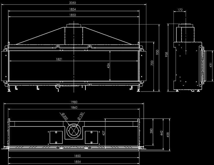
21 17.2 Modore
22 18 Parts Ontop flue material Installation manual On the following pages you will find a description of the components that can be used with the installation with the closed combustion system of this unit. The part number in the table refers to the number of the part on the following pages. This number is also the number that is used to designate components in the proposed installation schedules. Description pipe diameter. Ø150/100 Ø200/130 A Device B Connecting the device C Chimney Adapter D Chimney, gas-proof Ø150 minimum E Chimney, gas-proof Ø160 minimum F Stainless steel flexible chimney lining Ø100 G Stainless steel flexible chimney lining Ø150 1 Pipe concentric chimney pipe length 250mm US US Pipe concentric chimney pipe length 500mm US US Pipe concentric chimney pipe length 1000mm US US Clamp USKB 100 USKB Cover band USAB 100 USAB Adjustable pipe fitting mm USPP 100 USPP Roof transit USDVC Wall transit Ø100 USDHCE Assembly bracket USEB 100 USEB Adjustable wall bracket USMB 100 USMB Concentric curve 90 USB USB Concentric curve 45 USB USB Concentric curve 15 USB USB Storm collar USSR 100 USSR Roof sheeting flat roof (aluminium) USDPAL 100 USDPAL Roof sheeting flat roof (aluminium) USDP 100 USDP Roof sheeting sloping 5-30 USDH 100 USDH Roof sheeting sloping lead slab pane USLS 100 USLS Adjustable roof sheeting (supplied per pair) USCP 100 USCP Wall sheeting USMPG 100 USMPG Reducer Ø130 - Ø100 USVK Wall transit Ø130 USDHC
23 23
24 24
25 25
26 26
27 27
28 19 Warranty conditions If there are malfunctions that you cannot solve using the fault finder on pag 20, please contact your installer or your dealer. The Element4 products that are covered by this warranty card are carefully manufactured from high quality materials. If errors or defects still occur, then the following warranty coverage apply: 1) The installer will, before continuing with the installation, first check the proper quality and the smooth operation of the chimney system. The gas appliances should always be built in by a competent installer in accordance with the national and any regional standards and according to the installation instructions supplied with the unit. The warranty is not applicable in the following cases: 1) If the above points have not been met or where only partially met. 2) If unknown to E4 to, any changes were made to the appliance. 3) If the device was not built in according to the installation instructions, or not used according to the operating manual. 4) If there are any material other than the prescribed artificial wooden logs, ceramic material or stones on the burner bed. 2) The warranty period on the E4 gas appliances is 2 years counting from the date of purchase that must be mentioned clearly on the purchase invoice. 3) Not covered under warranty are the ceramic glass as well as external physical and chemical action during transport, storage or assembly. 4) If a malfunction should occur within the warranty period resulting from a manufacturing defect or material defect, Element4 will send the installer a free spare part to replace the defective part, without compensation for the mounting and dismounting 5) If the installer cannot resolve the fault itself, he may request Element4 BV to do so, if this is within the limits of the Benelux. 6) Only after prior consultation can the entire device or parts of it be sent in for inspection or repair. These goods must be accompanied by this completed warranty document along with the dated proof of purchase. 7) In case of a service at home by Element4 BV (only within Benelux) during the warranty period, the warranty documents (this page together with the dated proof of purchase) must be submitted. 8) With service at home out of the warranty period, the following fee will be charged: material costs, work hours and travel costs. 28
29
30
31
32 December 2015 Element4 B.V. Paxtonstraat RP Zwolle The Netherlands
Installation manual (EN/UK) Lucius 140 MKП
 Lucius 140 MKП") (EN/UK) Lucius 140 MKП Warning: The combustion chamber of this stove should only be opened and serviced by a registered gas installer. Leave these instructions as manual with the device Table of content
(EN/UK) Lucius 140 MKП Warning: The combustion chamber of this stove should only be opened and serviced by a registered gas installer. Leave these instructions as manual with the device Table of content
Relaxed Premium M Relaxed Premium M ENG
 Relaxed Premium M 40010959 1440 Relaxed Premium M ENG 3 alternative finishes. 1.1a 1.1b 1.1c 1 < < < < 1.2 1.3 7 1.4 2 < < < < 1.5 1.6 B 1.9 3 < < < < 2.1 2.2 2.3 3.1 3.2 3.3 3.4 4 < < < < 3.5 4.1 4.2
Duet Premium M Duet Premium M ENG
 Duet Premium M 40011422-1441 Duet Premium M ENG 1.1 1.2 1.3 1.4 1.5 1.6 1.7 1.8 1 < < < < 2.1 a 2.1 b 2.1 c A C 2.2 2 < < < < F F 2.3 X H X C 2.4 2.5 S T 3.1 3.2 R Q 3.3 3 < < < < 4.1 4.2 4.3 4.4 4 <
Clear Installation guide
 Clear 40010631-0938 ENG Installation guide ENG 1.1 1.2 1.3 A 1.4 1.5 1 < < < < A B 2.1 2.2 2.3 C 2.4 2.5 2 < < < < 3.1 3.2 3-3 3 < < < < Inhoudsopgave 1 Introduction... 6 2 Safety instructions... 6 3 Installation
Fyn Installation guide
 Fyn 600 4001131-1123 ENG Installation guide ENG 1.1 1.2 A B 1.3 1.4 1 < < < < 2.1 2.2 2.3 2.4 3.1 3.2 2 < < < < 4.1 4.2 4.3 4.4 3 < < < < 1 Introduction The appliance can only be installed by a competent
Fyn Installation guide
 Fyn 450 400100929-1114 ENG Installation guide ENG 1.1 1.2 A B 1.3 1.4 1 < < < < 2.1 2.2 2.3 3.1 3.2 2 < < < < 4.1 4.2 4.3 4.4 3 < < < < Table of contents 1 Introduction... 6 2 Safety instructions... 6
Duet Premium L Duet Premium L ENG
 Duet Premium L 40011297-1441 Duet Premium L ENG 1.1 1.2 1.3 1.4 1.5 1.6 1.7 1.8 1 < < < < 2.1 a 2.1 b 2.1 c A C 2.2 2 < < < < F F 2.3 X H X C 2.4 2.5 S T 3.1 3.2 R Q 3.3 3 < < < < 4.1 4.2 4.3 4.4 4 <
Duet XL /0929. Installation guide
 Duet XL 40010749/0929 ENG Installation guide ENG 1.1 1.2 1.3 1.4 1.5 A 1.6 1.7 1 < < < < B A 2.1 2.2 2.3 2.4 2 < < < < 2.5 2.6 2.7 2.8 3 < < < < 3.1 F F 3.2 3.3 4 < < < < Table of contents 1 Introduction...
Solution Installation guide
 Solution 40011444-1327 ENG Installation guide ENG 1-1 1-2 1-3 1.4 1 < < < < 2.1 2-3 2-4 2 < < < < 3-1 3.2 3-3 3.5 3.6 3 < < < < 4-1 A 4-2 4-3 4 < < < < Dimensions Terminal position Distance (For good working
User- and installation manual. Sky, Sky-T
 User- and installation manual Sky, Sky-T WARNING - THE COMBUSTION CHAMBER OF THIS STOVE SHOULD ONLY BE OPENED AND SERVICED BY A REGISTERED GAS INSTALLER (i.e. GAS SAFE REGISTERED ENGINEER[GB]) These instructions
Respect OC Installation manual
 Respect OC 40011335-1235 ENG Installation manual ENG 1.1 1.2 A 1.3 1.4 A A 2.1 2.2 2.3 1 < < < < 2.4 2.5 B C A B A 2.6 2 < < < < 3.1 3.2 3.3 3.4 3.5 3.6 3 < < < < A B 3.7 4 < < < < L A A 4.1 A A 4.2 A
Vaska Logburner. voorbeeld Installation guide
 Vaska ogburner voorbeeld 40010627-2103 ENG Installation guide ENG 1.1 1.2 1.3 1.4 1.5 1 < < < < 1 Introduction The appliance can only be installed by a competent person in accordance with the Gas Safety.
User manual (GB / IE) for appliances provided with an electronic ignition on the remote control. English. Read this document and store it carefully
 for appliances provided with an electronic ignition on the remote control. English. Read this document and store it carefully") User manual (GB / IE) for appliances provided with an electronic ignition on the remote control Read this document and store it carefully 958.007.07.uk 1 UK Contents page Preface 2 1. Introduction 3 2.
User manual (GB / IE) for appliances provided with an electronic ignition on the remote control Read this document and store it carefully 958.007.07.uk 1 UK Contents page Preface 2 1. Introduction 3 2.
VASKA B11. gas -fireplace installation guide
 VASKA B11 gas -fireplace installation guide Saturnus 8 NL-8448 CC Heerenveen Postbus 219 NL-8440 AE Heerenveen T. +31(0)513 656500 F. +31(0)513 656501 40 010 446 01 51 DESCRIPTION OF THE FIREPLACE CONTENTS
VASKA C11. gas -fireplace installation guide
 VASKA C11 gas -fireplace installation guide Saturnus 8 NL-8448 CC Heerenveen Postbus 219 NL-8440 AE Heerenveen T. +31(0)513 656500 F. +31(0)513 656501 40 010 459 01 51 DESCRIPTION OF THE FIREPLACE CONTENTS
VASKA C11. gas-fireplace user manual. Saturnus 8 NL-8448 CC Heerenveen Postbus 219 NL-8440 AE Heerenveen T. +31(0) F.
 F.") VASKA C11 gas-fireplace user manual Saturnus 8 NL-8448 CC Heerenveen Postbus 219 NL-8440 AE Heerenveen T. +31(0)513 656500 F. +31(0)513 656501 40 010 458 01.51 DESCRIPTION OF THE FIREPLACE CONTENTS 1 2
VASKA C11 gas-fireplace user manual Saturnus 8 NL-8448 CC Heerenveen Postbus 219 NL-8440 AE Heerenveen T. +31(0)513 656500 F. +31(0)513 656501 40 010 458 01.51 DESCRIPTION OF THE FIREPLACE CONTENTS 1 2
Dovre 250 Cast Iron Gas Stove
 Dovre 50 Cast Iron Gas Stove NATURAL GAS AND LPG INSTALLATION, SERVICING AND USER INSTRUCTIONS THIS PRODUCT IS FOR USE ONLY IN GREAT BRITAIN AND IRELAND These instructions are to be left with the customer,
PowerVent. Installation manual (GB) English. Store this document in a safe place UK
 English. Store this document in a safe place UK") PowerVent Installation manual (GB) Store this document in a safe place 959.034.03.UK GB Contents Blz Foreword 3 1. Introduction 3 2. CE declaration 4 3. SAFETY 4 3.1 General 4 3.2 Regulations 4 3.3 Precautions
PowerVent Installation manual (GB) Store this document in a safe place 959.034.03.UK GB Contents Blz Foreword 3 1. Introduction 3 2. CE declaration 4 3. SAFETY 4 3.1 General 4 3.2 Regulations 4 3.3 Precautions
LUNA 850 V GOLD GAS INSTRUCTION FOR INSTALLATION AND USE. Passion for fire
 LUNA 850 V GOLD GAS INSTRUCTION FOR INSTALLATION AND USE Passion for fire SUMMARY 1. GENERAL REMARKS...3 2. CONNECTION...3 3. SPECIFICATION SHEET...4 4. ASSEMBLY OF THE CHIMNEY...5-7 5. ELECTRICAL CONNECTION...8
Imperial Electric Fires
 Imperial Electric Fires GB IE MODELS: Flamescape II Curvascape II manual & remote. Installation and User Instructions PLEASE READ THESE INSTRUCTIONS CAREFULLY AND RETAIN FOR FUTURE REFERENCE This electric
User- and installation manual Trisore 140, Bidore 140, Modore 140, Trisore 95, Bidore 95, Modore 95, Trisore 70, Bidore 70, Modore 70.
 User- and installation manual Trisore 140, Bidore 140, Modore 140, Trisore 95, Bidore 95, Modore 95, Trisore 70, Bidore 70, Modore 70. WARNING - THE COMBUSTION CHAMBER OF THIS STOVE SHOULD ONLY BE OPENED
CORNER BELL SMALL 3 CF/LF
 INSTALLATION INSTRUCTIONS & MANUAL FOR MAINTENANCE CORNER BELL SMALL 3 CF/LF Gas fi res with closed combustion system Bellfi res wishes you many cosy evenings with your new Bellfi res gas fi re This document
ULTIMATE INSET LIVE FUEL EFFECT GAS FIRE MODEL 417 OWNER GUIDE
 ULTIMATE INSET LIVE FUEL EFFECT GAS FIRE MODEL 417 OWNER GUIDE THE NATURAL GAS MODEL IS FOR G20 AT A SUPPLY PRESSURE OF 20mbar THE PROPANE GAS MODEL IS FOR G31 AT A SUPPLY PRESSURE OF 37mbar THESE APPLIANCES
GB IE. VALOR BOLERO (MODEL BR626) Inset Decorative Fuel Effect Gas Fires. For
 Inset Decorative Fuel Effect Gas Fires. For") O W N E R G U I D E For VALOR BOLERO (MODEL BR626) Inset Decorative Fuel Effect Gas Fires GB IE This Owner Guide is intended to help you care for your Valor gas fire. Please read carefully before using
O W N E R G U I D E For VALOR BOLERO (MODEL BR626) Inset Decorative Fuel Effect Gas Fires GB IE This Owner Guide is intended to help you care for your Valor gas fire. Please read carefully before using
VIEW BELL VERTICAL 3 CF/LF
 INSTALLATION INSTRUCTIONS & MANUAL FOR MAINTENANCE VIEW BELL VERTICAL 3 CF/LF Gas fi res with closed combustion system Bellfi res wishes you many cosy evenings with your new Bellfi res gas fi re This document
CRYSTAL FIRES. Inset Conventional Flue Fire. (BOSTON/MIAMI) Cf1 and MANHATTAN USER INSTALLATION AND SERVICING INSTRUCTIONS
 Cf1 and MANHATTAN USER INSTALLATION AND SERVICING INSTRUCTIONS") CRYSTAL FIRES (BOSTON/MIAMI) Cf1 and MANHATTAN Inset Conventional Flue Fire USER INSTALLATION AND SERVICING INSTRUCTIONS FOR USE WITH NATURAL GAS G20 @ 20 mbar For use in GB and IE CE THESE INSTRUCTIONS
CRYSTAL FIRES (BOSTON/MIAMI) Cf1 and MANHATTAN Inset Conventional Flue Fire USER INSTALLATION AND SERVICING INSTRUCTIONS FOR USE WITH NATURAL GAS G20 @ 20 mbar For use in GB and IE CE THESE INSTRUCTIONS
(manual control) (ezi-slide control) INSET COAL EFFECT GAS CONVECTOR FIRE V1/100/B INSTALLATION & USER INSTRUCTIONS
 (ezi-slide control) INSET COAL EFFECT GAS CONVECTOR FIRE V1/100/B INSTALLATION & USER INSTRUCTIONS") Model Number: V1/100/A V1/100/B (manual control) (ezi-slide control) INSET COAL EFFECT GAS CONVECTOR FIRE INSTALLATION & USER INSTRUCTIONS GB IE SUITABLE FOR USE ON NATURAL GAS (G20) AT 20mbar SUPPLY PRESSURE
Model Number: V1/100/A V1/100/B (manual control) (ezi-slide control) INSET COAL EFFECT GAS CONVECTOR FIRE INSTALLATION & USER INSTRUCTIONS GB IE SUITABLE FOR USE ON NATURAL GAS (G20) AT 20mbar SUPPLY PRESSURE
INSTALLATION INSTRUCTIONS COMPACT GAS STOVE MODEL NUMBER 550
 INSTALLATION INSTRUCTIONS COMPACT GAS STOVE MODEL NUMBER 550 Before installation ensure that the local distribution conditions (identification of the type of gas and pressure) and the adjustment of the
INSTALLATION & USERS INSTRUCTIONS. FOR USE WITH NATURAL GAS 20 mbar For use in GB and IE
 1 valentine s buildings Bechers drive Aintree racecourse Business Park L9 5ay CF1 L GAS APPLIANCE INSET CONVENTIONAL FLUED GAS FIRE INSTALLATION & USERS INSTRUCTIONS FOR USE WITH NATURAL GAS G20 @ 20 mbar
MODEL 466 Radiant / Convector Gas Fire Black Beauty
 O W N E R G U I D E MODEL 466 Radiant / Convector Gas Fire Black Beauty This Owner Guide is intended to help you care for your Valor gas fire. Please read carefully before using your gas fire and keep
Torch framed Installation Guide
 Torch framed 40010567-0602 Installation Guide 1 2 3 4 1 < < < < 5 6 7 > > > > 2 Content 1 Introduction... 1 2 Safety Instructions... 2 3 Installation requirements... 3 3.1 Rear surface construction...
HUNTER HAWK 4 MKII GAS STOVE
 HUNTER HAWK 4 MKII GAS STOVE User Instructions Please leave this instruction booklet with the user after the installation is complete. Leave the system ready for operation and instruct the user in the
INSTALLATION, USERS AND SERVICING INSTRUCTIONS
 INSTALLATION, USERS AND SERVICING INSTRUCTIONS SLIMLINE (FAN FLUE) HOTBOX Inset Decorative coal or pebble effect Gas Fire For use with Natural Gas (G20) @ 20mbar or Butane (G30) @ 28mbar or Propane (G31)
SAUNA HEATER INSTALLATION AND OPERATING MANUAL
 SAUNA HEATER INSTALLATION AND OPERATING MANUAL Type Stoveman 13 Models 13R; 13R-M; 13; 13-M; 13R-LS; 13R-M-LS; 13-M-LS; 13-LS Heating output in the sauna room 15.4 kw Sauna room cubage 6-13 m³ Fuel Wood
Kalahari DECORATIVE FUEL EFFECT GAS FIRE
 Kalahari DECORATIVE FUEL EFFECT GAS FIRE User Instructions These instructions should be read by the user before operating the appliance and retained for future reference Model No. KRDC00MN & KRDC00SN are
Orchestra COAL EFFECT BALANCED FLUE GAS FIRE
 Orchestra COAL EFFECT BALANCED FLUE GAS FIRE Installation and Maintenance Instructions Hand these instructions to the user Model No s FBFN76G & FBFN98G are for use on Natural Gas (G20) at a supply pressure
GB IE INSTALLATION & USER INSTRUCTIONS. Model Number: V1/300/B (ez-slide control) HIGH EFFICIENCY INSET COAL EFFECT GAS CONVECTOR FIRE
 HIGH EFFICIENCY INSET COAL EFFECT GAS CONVECTOR FIRE") Model Number: V1/300/B (ez-slide control) HIGH EFFICIENCY INSET COAL EFFECT GAS CONVECTOR FIRE INSTALLATION & USER INSTRUCTIONS GB IE SUITABLE FOR USE ON NATURAL GAS (G20) AT 20mbar SUPPLY PRESSURE These
Model Number: V1/300/B (ez-slide control) HIGH EFFICIENCY INSET COAL EFFECT GAS CONVECTOR FIRE INSTALLATION & USER INSTRUCTIONS GB IE SUITABLE FOR USE ON NATURAL GAS (G20) AT 20mbar SUPPLY PRESSURE These
GrateGlow THE ALL NEW CAPITAL COLLECTION. G20 at 20mbar convertible to G31 at 37mbar. For use in GB and le. Users Instructions
 GrateGlow A CARVER GROUP COMPANY --..--... THE GAS CONSUMERS' COUNCIL (GCC) IS AN INDEPENDENT ORGANISATION WHICH PROTECTS THE INTEREST OF GAS USERS. IF YOU NEED ADVICE, YOU WILL FIND THE TELEPHONE NUMBER
INSTALLATION AND MANINTENANCE INSTRUCTIONS
 INSTALLATION AND MANINTENANCE INSTRUCTIONS Appr. Nr. A 9503 T - 0085 AQ 0765 PEGASUS F2 T HIGH EFFICIENCY GAS-FIRED CAST-IRON BOILERS Models 51-68 - 85-102 2 Contents 1. General technical data 2. Dimensional
COAL EFFECT BALANCED FLUE GAS FIRE
 Raglan COAL EFFECT BALANCED FLUE GAS FIRE Installation and Maintenance Instructions Hand these instructions to the user Model No. KBFC**MN for use on Natural Gas (G20) at a supply pressure of 20 mbar in
Installation Instructions Horizon Natural Draft Electronic Ignition Gas Fireplaces
 Installation Instructions Horizon Natural Draft Electronic Ignition Gas Fireplaces Installation Instructions Horizon Natural Draft Electronic Ignition 3 Sided Gas Fireplaces Natural Draft Electronic Ignition
VENTO CLASSIC MEDIUM
 INSTRUCTIONS FOR USE & MANUAL DAILY MAINTENANCE VENTO CLASSIC MEDIUM Gas fi re with closed combustion system Bellfi res wishes you many cosy evenings with your new Bellfi res gas fi re This document is
OWNER GUIDE. Model 739 OPEN DECORATIVE GAS FIRE. (GC No )
") 5113426/01 OWNER GUIDE Model 739 OPEN DECORATIVE GAS FIRE (GC No. 32-032-54) THIS APPLIANCE IS FOR USE WITH NATURAL GAS (G20). WHEN CONVERTED USING CONVERSION KIT NO. 0595211 THIS APPLIANCE IS FOR USE
5113426/01 OWNER GUIDE Model 739 OPEN DECORATIVE GAS FIRE (GC No. 32-032-54) THIS APPLIANCE IS FOR USE WITH NATURAL GAS (G20). WHEN CONVERTED USING CONVERSION KIT NO. 0595211 THIS APPLIANCE IS FOR USE
Decorative Fuel Effect Appliances
 Decorative Fuel Effect Appliances Technical Manual User and Installation Instructions for CUBB22US Available in Natural Gas. 1 Contents Section Pages 1 Unpacking 3 2 Installation Parameters 4 3 Installation
Sonnet Plus Anthem Genesis Soraya
 5108617/01 OWNER GUIDE Sonnet Plus Anthem Genesis Soraya Model 746 (GC No. 32-032-57) INSET LIVE FUEL EFFECT GAS FIRE THIS APPLIANCE IS FOR USE WITH NATURAL GAS (G20) WHEN CONVERTED USING CONVERSION KIT
OWNER S GUIDE MODEL BR417 VA
 600B702/06 OWNER S GUIDE MODEL BR417 VA (G.C.32-032-07) Inset Live Fuel Effect Gas Fire with Ultimate Front AS SUPPLIED, THIS APPLIANCE IS FOR USE WITH NATURAL GAS (G20) WHEN CONVERTED USING VALOR CONVERSION
PowerVent. Installation manual (GB) English. Store this document in a safe place UK
 English. Store this document in a safe place UK") PowerVent Installation manual (GB) Store this document in a safe place 959.078.00.UK GB Contents page Foreword 3 1. Introduction 3 2. CE declaration 4 3. SAFETY 4 3.1 General 4 3.2 Regulations 4 3.3 Precautions
PowerVent Installation manual (GB) Store this document in a safe place 959.078.00.UK GB Contents page Foreword 3 1. Introduction 3 2. CE declaration 4 3. SAFETY 4 3.1 General 4 3.2 Regulations 4 3.3 Precautions
Metro 70 - Metro 70 Tunnel
 Metro 70 - Metro 70 Tunnel G31 propane Instructions for installation (GB / IE) Please retain this document carefully UK Contents page Foreword 2 1. Introduction 3 2. EC Declaration of Conformity 3 3. SAFETY
MOCCA CUBIC AUS/NZ. 08/53066/0 Issue 2
 MOCCA CUBIC AUS/NZ 08/53066/0 Issue 2 The product complies with the European Safety Standards EN60335-2-30 and the European Standard Electromagnetic Compatibility (EMC) EN55014, EN60555-2 and EN60555-3
Curvation & Siesta Models
 Curvation & Siesta Models Installation, Servicing & User Instructions For use in GB & IE (United Kingdom and Ireland) This appliance has been tested and certified for other counties (see technical data).
Limours. Balanced Flue Room Heater MODEL NUMBER : KBFP00RN INSTALLATION, USER AND SERVICING INSTRUCTIONS THESE INSTRUCTIONS MUST REMAIN WITH THE USER
 Limours Balanced Flue Room Heater MODEL NUMBER : KBFP00RN INSTALLATION, USER AND SERVICING INSTRUCTIONS THESE INSTRUCTIONS MUST REMAIN WITH THE USER This appliance is suitable for use on Natural Gas (G20)
Installation instruction
 Installation instruction Ci50 www.contura.eu 82 CERTIFICATE Declaration of performance according to Regulation (EU) 305/2011 No. Ci50-CPR-150821-SE-2 PRODUCT Product type Type designation Manufacturing
OWNER S GUIDE ETERNITY. MODEL 540C (GC No ) INSET BALANCED FLUE GAS FIRE
 INSET BALANCED FLUE GAS FIRE") 600B637/02 ETERNITY MODEL 540C (GC No. 32-032-19) INSET BALANCED FLUE GAS FIRE THIS APPLIANCE IS FOR USE WITH NATURAL GAS (G20) THIS APPLIANCE IS FOR USE IN THE UNITED KINGDOM (GB) AND THE REPUBLIC OF
600B637/02 ETERNITY MODEL 540C (GC No. 32-032-19) INSET BALANCED FLUE GAS FIRE THIS APPLIANCE IS FOR USE WITH NATURAL GAS (G20) THIS APPLIANCE IS FOR USE IN THE UNITED KINGDOM (GB) AND THE REPUBLIC OF
Sonnet Plus Anthem Genesis Soraya
 5110524/01 OWNER GUIDE Sonnet Plus Anthem Genesis Soraya Model 747 (GC No. 32-032-51) INSET LIVE FUEL EFFECT GAS FIRE THIS APPLIANCE IS FOR USE WITH NATURAL GAS (G20) WHEN CONVERTED USING CONVERSION KIT
Installation instruction
 Installation instruction C i40 www.contura.eu 82 CERTIFICATE Declaration of performance according to Regulation (EU) 305/2011 No. Ci40-CPR-130912-SE-2 PRODUCT Product type Type designation Manufacturing
Emberglow COAL EFFECT BALANCED FLUE GAS FIRE
 Emberglow COAL EFFECT BALANCED FLUE GAS FIRE User Instructions These instructions should be read by the user before operating the appliance and retained for future reference Model No. FEBC00MN is only
Installation Manual EF5000 AUS & NZ
 Installation Manual EF5000 AUS & NZ This manual is ONLY for fires with a serial No. from 80600 to 80999. Important: The appliance shall be installed in accordance with; Local gas fitting regulations Municipal
Gas Instantaneous Water Heater
 6 720 607 823 GB (06.06) SM Installation and Operating Instructions Gas Instantaneous Water Heater WR10..B... WR11..B... With electronic ignition and triple safety system consisting of ionisation detector,
OWNER GUIDE. Model 750. INSET LIVE FUEL EFFECT GAS FIRE Fitted with Harmony, Avignon or Style fascia. (GC No )
") 5112499/01 OWNER GUIDE Model 750 INSET LIVE FUEL EFFECT GAS FIRE Fitted with Harmony, Avignon or Style fascia (GC No. 32-032-58) THIS APPLIANCE IS FOR USE WITH NATURAL GAS (G20) WHEN CONVERTED USING CONVERSION
5112499/01 OWNER GUIDE Model 750 INSET LIVE FUEL EFFECT GAS FIRE Fitted with Harmony, Avignon or Style fascia (GC No. 32-032-58) THIS APPLIANCE IS FOR USE WITH NATURAL GAS (G20) WHEN CONVERTED USING CONVERSION
INSTALLER S GUIDE. MODEL 639 Open Decorative Gas Fire
 3002369/03 INSTALLER S GUIDE MODEL 639 Open Decorative Gas Fire (G.C No. 32-032-47) THIS APPLIANCE IS FOR USE WITH NATURAL GAS (G20) WHEN CONVERTED USING CONVERSION KIT NO. 0591301 THIS APPLIANCE IS FOR
Installation & Manual. Model T-25
 Installation & Manual TR Central Heating Stove With Solid Fuel Model T-25 Tested according to DIN EN 13240 For product efficiency and emission values, see the declaration of conformity! TABLE OF CONTENTS
User Guide Compact-7 series
 User Guide Compact-7 series Boiler-CH Calorifier Combi Introductory remarks Congratulations on the purchase of your Kabola Compact 7. Kabola has been a manufacturer of oil-fired heating systems since 1947.
JUNEAU JUN. 08/51193/0 Issue 0
 JUNEAU JUN 08/51193/0 Issue 0 The product complies with the European Safety Standards EN60335-2-30 and the European Standard Electromagnetic Compatibility (EMC) EN55014, EN60555-2 and EN60555-3 These cover
Table Top Patio Heater
 Table Top Patio Heater INSTRUCTION MANUAL MODEL: HPS-B Certified by international recognized standards. The infra-red with heat wave outdoor heater. Variable control gas valve with electric push igniter.
ANTIBACTERIAL HAND VAC WITH UV LIGHT
 User manual ANTIBACTERIAL HAND VAC WITH UV LIGHT CVH5743M 02/12 HOME APPLIANCES 1) Press the lever down. 2) Insert the vacuum cleaner while holding the lever down. 3) Once the vacuum cleaner is inserted
FLAME HEATER PYRAMID CLFH-10SS OPERATION INSTRUCTIONS
 FLAME HEATER PYRAMID CLFH-10SS OPERATION INSTRUCTIONS www.colorato.net For outdoors use only Uses propane, butane or LPG only Reflector: 47x47 mm Total Height: 2250 mm Regulator s external pressure: 28-30
Squirrel - Gas Stoves
 Squirrel - Gas Stoves Model No. 551 - With Open Flue INSTALLATION INSTRUCTIONS This appliance is for use with natural gas (G20) When converted using conversion kit no. 555111 this appliance is for use
Installation Manual EF5000 NZ
 Installation Manual EF5000 NZ Important: The appliance shall be installed in accordance with; Local gas fitting regulations Municipal building codes AS/NZS 5601.1.1:2010 Gas Installation Any other relevant
Model BR660VA Heat Engine
 5112253/01 Model BR660VA Heat Engine POWER FLUE INSET GAS FIRE (GC No. 32-032-44) THIS APPLIANCE IS FOR USE WITH NATURAL GAS (G20). WHEN CONVERTED USING CONVERSION KIT NO. 0591149 THIS APPLIANCE IS FOR
EMBERGLOW CLASSIC RADIANT CONVECTOR GAS FIRE. Installation and Maintenance Instructions
 , EMBERGLOW CLASSIC RADIANT CONVECTOR GAS FIRE Installation and Maintenance Instructions Hand these instructions to the user Model No. FEMC00MN is for use on Natural Gas (G20) at a supply pressure of 20
VIEW BELL SMALL 3 CF/LF
 INSTALLATION INSTRUCTIONS & MANUAL FOR MAINTENANCE VIEW BELL SMALL 3 CF/LF Gas fi res with closed combustion system Bellfi res wishes you many cosy evenings with your new Bellfi res gas fi re This document
Riva2 530/670. Inset Convector Fire - Balanced Flue. With Thermostatic Remote Control. Instructions for Use, Installation & Servicing
 Riva2 530/670 Inset Convector Fire - Balanced Flue With Thermostatic Remote Control IMPORTANT: For easy to follow, step by step video instructions on how to operate and maintain your Gazco remote system
STRATA BATTERY IGNITION RADIANT CONVECTOR GAS FIRE
 STRATA BATTERY IGNITION RADIANT CONVECTOR GAS FIRE Installation, Maintenance & User Instructions Hand these instructions to the user Model No s FORS**EN are for use on Natural Gas (G20) at a supply pressure
C D INSTALLATION 16 INSTALLER GENERAL INFORMATION
 INSTALLATION GENERAL INFORMATION This appliance is sealed from the surrounding environment in which it is installed and consequently combustion air is only aspired from outside! - When installing, NEVER
OWNER GUIDE. Anthem, Bolero, Camden, Minima, Victorian or Westminster fascia
 5114465/01 OWNER GUIDE Model 741 INSET LIVE FUEL EFFECT GAS FIRE Fitted with Anthem, Bolero, Camden, Minima, Victorian or Westminster fascia (GC No. 32-032-56) THIS APPLIANCE IS FOR USE WITH NATURAL GAS
Imperial Electric Fires
 Imperial Electric Fires GB IE MODELS: Flamescape III & Curvascape III manual / remote Installation and User Instructions PLEASE READ THESE INSTRUCTIONS CAREFULLY AND RETAIN FOR FUTURE REFERENCE This electric
INSTALLATION, OPERATION AND MAINTENANCE. Ariterm Vedo
 INSTALLATION, OPERATION AND MAINTENANCE Ariterm Vedo CONTENTS General...3 Installation...4-5 Laddomat 21 Connection diagram...6 Temperature control valve...7 About burning wood...8 Operation...9-11 Service
Propane Heater REMKO PGM 30 REMKO PGM 60
 Propane Heater REMKO PGM 30 REMKO PGM 60 Operation Technology Spare Parts Edition GB L07 REMKO strong as a bear. Operating instructions Make sure to read these instructions carefully before starting/using
USHO COOKER INSTALLATION INSTRUCTIONS SAFETY INSTRUCTIONS USER INSTRUCTIONS MODEL: USHO. INSTRUCTION REF: IN152 ISSUE No. 4 DATE
 Page 1 of 11 INSTALLATION INSTRUCTIONS SAFETY INSTRUCTIONS USER INSTRUCTIONS USHO COOKER MODEL: USHO Page 2 of 11 WARNING To avoid scratching the highly polished exterior surface of this equipment whilst
INSET LIVE FUEL EFFECT GAS FIRE
 600B741/02 OWNER S GUIDE MODEL BR650 VA (GC No. 32-032-39) INSET LIVE FUEL EFFECT GAS FIRE THIS APPLIANCE IS FOR USE WITH NATURAL GAS (G20) WHEN CONVERTED USING CONVERSION KIT NO.591149 THIS APPLIANCE
Installation & User Instructions: Model: e600s e600gf e700s e1000s e1000gf e1030gf/2/3 e1500gf/2/3
 Installation & User Instructions: Model: e600s e600gf e700s e1000s e1000gf e1030gf/2/3 e1500gf/2/3 Once installed, the installer should take the appropriate steps To ensure that the user understands how
Hestia Installation Guide
 Hestia 40010610-0746 UK Installation Guide Content 1.1 1.2 1.3 1.4 A B C D 1.5 1.6 1 < < < < Hestia with Wirdum Surround 2.1 2.2 2.3 2.4 2.5 2.6 > > > > 2 Hestia with Jellum Surround 3.1 3.2 3.3 3.4 3.5
INSTALLATION INSTRUCTIONS & MANUAL FOR MAINTENANCE DERBY LARGE 3 CF/LF. Gas fi re with closed combustion system
 INSTALLATION INSTRUCTIONS & MANUAL FOR MAINTENANCE DERBY LARGE 3 CF/LF Gas fi re with closed combustion system Bellfi res wishes you many cosy evenings with your new Bellfi res gas fi re This document
Installation and user manual CLOSED WOOD FIRES DON T COMPROMISE.
 Installation and user manual EN CLOSED WOOD FIRES DON T COMPROMISE. Product Product group Application Models Kalfire W Wood burning fireplaces with lifting door Open and closed Kalfire W45/48F Kalfire
Kalahari RC & Camber RC
 Kalahari RC & Camber RC DECORATIVE FUEL EFFECT GAS FIRE User Instructions These instructions should be read by the user before operating the appliance and retained for future reference Model No s KRDC**RN
LUNA H GOLD GAS INSTRUCTION FOR INSTALLATION AND USE
 LUNA 700-1000-1150-1300-1600-1900 H GOLD GAS INSTRUCTION FOR INSTALLATION AND USE UK 11-2012 1 V E R Y I M P O R T A N T I N S T A L L A T I O N I N S T R U C T I O N S F O R T H E M - D E S I G N G A
5. Wok setting (wok burner) 6. Roasting setting (wok burner)
 6. Roasting setting (wok burner)") OPERATION Description 6 5 7 8 9 0 Ignition and adjustment. zone indication. 0 position. High setting. Low setting 5. Wok setting (wok burner) 6. Roasting setting (wok burner). rapid burner. standard burner.
OPERATION Description 6 5 7 8 9 0 Ignition and adjustment. zone indication. 0 position. High setting. Low setting 5. Wok setting (wok burner) 6. Roasting setting (wok burner). rapid burner. standard burner.
INSTRUCTIONS MANUAL FOR USE AND MAINTENANCE
 INSTRUCTIONS MANUAL FOR USE AND MAINTENANCE Carbel models: C-60 Plus C-70 Plus C-80 Plus C-100 Plus C-70 Plus Double-sided C-80 Plus Double-sided C-100 Plus Double-sided CARBEL C/ Ciudad de Cartagena,
Baxi Brazilia F5, F5S & F8S
 Baxi Brazilia F5, F5S & F8S Balanced Flue Gas Wall Heaters Comp No. 243469 - Iss 1-6/99 Installation and Servicing Instructions Natural Gas Baxi Brazilia F 5 G.C.No. 35 075 0lA Baxi Brazilia F 5S Grey
Model 341 Black Beauty Slimline
 600B690/13 OWNER GUIDE Model 341 Black Beauty Slimline LIVE FUEL EFFECT GAS FIRE (GC No. 32-032-30) We trust that this guide gives sufficient details to enable this appliance to be operated and maintained
INSTALLATION INSTRUCTIONS SAFETY INSTRUCTIONS USER INSTRUCTIONS PARAGON GAS SALAMANDER
 Page 1 of 9 INSTALLATION INSTRUCTIONS SAFETY INSTRUCTIONS USER INSTRUCTIONS PARAGON GAS SALAMANDER MODEL : 7072 & 7073 Page 2 of 9 WARNING To avoid scratching the highly polished exterior surface of this
morsø PANTHER GAS STOVE
 morsø PANTHER GAS STOVE MODEL No. 553 OWNER S GUIDE This appliance meets the requirements of the European Gas Directive This guide is intended to help you care for your morsø gas stove. It gives sufficient
IDE 20 / IDE 30 / IDE 50 IDE 60 / IDE 80
 IDE 20 / IDE 30 / IDE 50 IDE 60 / IDE 80 EN OPERATING MANUAL OIL HEATER TRT-BA-IDE20-30-50-60-80-TC-001-EN Table of contents Information on the use of this manual... 1 Scope of delivery... 1 General safety...
USER S MANUAL, MAINTENANCE MANUAL INSTALLATION INSTRUCTIONS
 D F:\Home\RD\ME\FUNNY\FUNNYGB.WP IN-FIRE Jubilee USER S MANUAL, MAINTENANCE MANUAL INSTALLATION INSTRUCTIONS 07DHIFFUA 03/99-1 - Dear Customer! Congratulations on the purchase of your new Bodart & Gonay
Charlotte CRT20AB, Charlotte CRT20BR & Brookline BKL20
 Charlotte CRT20AB, Charlotte CRT20BR & Brookline BKL20 08/51007/0 Issue 1 The product complies with the European Safety Standards EN60335-2-30 and the European Standard Electromagnetic Compatibility (EMC)
Model 741FS. Dream, Heritage or Opulent OWNER GUIDE. INSTALLER: Please leave this guide with the owner Baxi Heating U.K. Limited 2007.
 5112500/02 Model 741FS Inset live fuel effect gas fire Incorporating the BAXI FIRES DIVISION CONTROL Fitted with one of the following fascia. Dream, Heritage or Opulent (GC No. 32-032-56) We trust that
Dovre 700CBW Cast Iron Wood Stove INSTALLATION INSTRUCTIONS 700G/1095
 Dovre 700CBW Cast Iron Wood Stove INSTALLATION INSTRUCTIONS 700G/1095 Before commencing with the installation it is important that these instructions are read and fully understood. The DOVRE 700CBW is
Riva2 F670. including optional Apex Stand and Bench. Conventional Flue with Thermostatic Remote Control
 Riva2 F670 including optional Apex Stand and Bench Conventional Flue with Thermostatic Remote Control IMPORTANT: For easy to follow, step by step video instructions on how to operate and maintain your
Firefox 5. Model 910 CAST-IRON GAS STOVE. Fitted with a Ceramic Coal fuel effect. INSTALLER: Please leave this guide with the owner
 DATA LIBRARY Catalog» Valor» Stove» Firefox» Firefox 5 (GC No. 3226424)» Installation Instructions» Firefox 5 Model 910 iss 01 INSTALLER GUIDE Firefox 5 Model 910 CAST-IRON GAS STOVE Fitted with a Ceramic
This appliance must be installed and serviced by a competent person as stipulated by the Gas Safety (Installation & Use) Regulations.
 Regulations.") G3512 and G3532 DOMINATORPLUS Grills INSTALLATION and SERVICING INSTRUCTIONS This appliance must be installed and serviced by a competent person as stipulated by the Gas Safety (Installation & Use) Regulations.
G3512 and G3532 DOMINATORPLUS Grills INSTALLATION and SERVICING INSTRUCTIONS This appliance must be installed and serviced by a competent person as stipulated by the Gas Safety (Installation & Use) Regulations.