Metro 70 - Metro 70 Tunnel
|
|
|
- Andrea Flynn
- 5 years ago
- Views:
Transcription
 Please retain this document")
1 Metro 70 - Metro 70 Tunnel G31 propane Instructions for installation (GB / IE) Please retain this document carefully UK
2 Contents page Foreword 2 1. Introduction 3 2. EC Declaration of Conformity 3 3. SAFETY General Regulations Precautionary measures / safety instructions regarding installation 3 4. Instructions 4 5. Unpacking 4 6. Installation Regulations Gas type Gas connection Positioning the appliance Flue / combustion air supply system Building the chimney breast Installing the control box Adjusting the appliance Arranging the logs / pebbles Glass window Wireless remote control Receiver Final inspection Gastightness Gas pressure/pre-pressure Igniting the pilot and main burner Flame effect Maintenance Completion Troubleshooting 20 Annex 1 Components supplied 23 Annex 2 Technical data 23 Annex 3 Spare parts 23 Foreword!Tip As manufacturer of gas heating appliances, DRU develops and produces products to meet the highest possible quality, performance and safety requirements. As a result of which the user is able to enjoy using your appliance for years to come. This appliance is CE marked; it complies with the essential requirements of the European Appliance Directive. The appliance is supplied with two manuals: the installation manual and the user manual. You the installer should be professionally skilled in the fi eld of decorative gas heating. The installation manual gives you all the information you will need to be able to install the appliance in such a way that it works correctly and safely. This manual deals with the installation of the appliance and the appropriate regulations. It also includes the technical data for the appliance and information on maintenance and troubleshooting. Please read and use this installation manual carefully. In the manuals the following symbols are used to denote important information: What to do Suggestions and recommendations These instructions are important to avoid possible problems during installation and/or use. These instructions are important to avoid fire, personal injury or other serious damage. Once you have completed the installation you are to hand both the user manual and this installation manual to the user. UK 2
3 1. Introduction The appliance is supplied in two versions, the Metro 70 and the Metro 70 tunnel. This version of the Metro 70 and the Metro 70 tunnel is suitable for propane gas. The safe operation of the appliance is guaranteed by the use of a second thermocouple fi tted to the main burner. The Metro 70 is a standard appliance. It is always mounted against a wall. The Metro 70 tunnel is a look-through appliance ; it has a pane at the font and back. The Metro 70 and Metro 70 tunnel are room-sealed atmospheric gas-fi red heating appliances. A room-sealed appliance does not extract the combustion air from the living environment, but from outside. This is done by means of a combined flue gas discharge system / combustion air supply system. In this concentric system, the outer pipe functions as the air supply and the inner pipe functions as the flue gas discharge. This system can be installed through the wall or through the roof. These appliances are built within a chimney breast. In order to reach a proper heat discharge, the chimney breast must be ventilated. DRU is able to supply various ventilation elements. The appliances are supplied with a wireless remote control that works on batteries. 2. EC Declaration of Conformity We hereby declare that the design and construction of the decorative gas heating appliance marketed by DRU conforms with the essential requirements of the Gas Appliance Directive. This declaration will be rendered invalid should the appliance be altered in any way without the written consent of DRU. Product: Decorative gas heating appliance Type: Metro 70 Metro 70 Tunnel Applicable EC Directives: 90/396/EEC Applicable harmonised standards: NEN-EN-613 NEN-EN-613/A1 In-house measures guarantee that serially produced appliances always conform with the essential requirements of the current EC Directives and the applicable standards. R. Gelten DRU VERWARMING B.V. Postbus 1021, 6920 BA Duiven Ratio 8, 6921 RW Duiven 3. SAFETY 3.1 General - Please read this chapter on safety carefully before commencing installation or maintenance - Always observe universal regulations and the precautionary measures / safety instructions in this manual. 3.2 Regulations The appliance should be installed in compliance with current national, local and constructional (installation) regulations. 3.3 Precautionary measures / safety instructions regarding installation Observe the following precautions / safety regulations precisely: You may only install and/or service this appliance if your are a qualified installer skilled in installing decorative gas fires; do not adjust the appliance in any way; use incombustiblei and heat-resistant materials for building a chimney breast, including the back wall, the inside and the top of the chimney breast; the minimum internal dimensions required for the chimney breast must be taken into account; the chimney breast should be ventilated by vents with total free vent area of 200 cm 2 ; only use the flue /combustion air supply systems supplied by DRU; use the wall brackets supplied to mount the appliance; do not install the appliance flat against the back wall; leave the space between the feet free; do not cover and/or pack the appliance with an insulating blanket or any other material; Make sure combustible objects and / or materials have a minimum distance from the appliance of 500 mm; only use the log/pebble set supplied; 3 UK
4 arrange the logs/pebbles exactly as described; make sure the pilot burner and the space around it is kept free; make sure thermocouple 2 and the space around it are kept free; avoid any dirt in the gas pipes and connections; test the gastightness of all connections before use; use heat-resistant electrical connection materials; install the electrical connections away from the appliance; avoid blocking the explosion hatch/hatches; ensure the explosion hatch/hatches on top of the heater are right on their seats, before you close the chimney breast; do not ignite the appliance until installation has been completed. 4. Instructions To ensure the appliance works correctly and safely, always take the following points into consideration during installation: place the control box supplied as low as possible; ensure the ignition wire does not lie across the receiver; ensure the ignition wire does not touch or cross the aerial; to avoid weakening the spark ensure the ignition wire does not touch anything metal; if the appliance is to be built in flush with the wall, finish the edges neatly; do not plaster over the flanges; avoid damaging the glass when removing/fitting the window pane; to prevent dirt burning into the glass, make sure it is clean before use; make sure that the wires of thermocouple 2 cannot come into contact with hot parts. 5. Unpacking Please take the following points into consideration when unpacking the appliance: Check the appliance for transit damage; Contact DRU Service if necessary; Once the packaging material has been removed, you should have the following components: - Socket spanner: You will fi nd this in the space between the assembly frame and the combustion chamber. - Trimmings: These are in the same space. Once you have removed the glass pane you can remove the box of components from the combustion chamber. Be careful not to damage the glass when removing/fitting the window pane. Remove the window as described in paragraph Take the box of components out of the combustion chamber. Annex 1 / Table 4 specifi es the components you should have once everything has been unpacked. Contact DRU Service if after unpacking the appliance you do not have all the components. Dispose of the packaging in an appropriate manner. 6. Installation Please read the manual carefully to ensure that once installed the appliance will work correctly and safely. Install the appliance in the order described in this chapter. 6.1 Regulations - Observe the current applicable (installation) regulations. - Observe the regulations/instructions laid down in this manual. 6.2 Gas type The type plate specifi es the type of gas, gas pressure, and the country this appliance is intended for. The type plate is on a chain and that is where it should stay. Check that the appliance is suitable for the local gas type and pressure. 6.3 Gas connection The gas connection should have a gas tap located near the appliance. Prevent any dirt getting into the gas pipes or connections. The following requirements apply for the gas connection: the size of the gas pipe should be such that no pressure loss can occur; the gas tap must be CE marked; UK 4
5 METRO 70 - I N S T R U C T I O N F O R I N S TA L L AT I O N the gas tap should be accessible at all times. Do not twist the gas tap when connecting the gas pipe. 6.4 Positioning the appliance Position the fire as follows: - Make sure combustible objects and / or materials have a minimum distance from the appliance of 500 mm; - Do not adjust the appliance in any way. Determine the position of the appliance. Create a gas connection in the appropriate position; see section 0 for details. Create a duct for the flue / combustion air supply system, with the diameter shown below; see section 6.5 for details. Ø160 mm for a wall duct of incombustible material; Ø 250 mm for a wall duct of combustible material Ø160 mm for a roof duct of incombustible material; Ø 250 mm for a roof duct of combustible material - Allow for the depth of the appliance (see Fig. 2) (Metro 70: minimum of 400 mm; Metro 70 Tunnel: minimum of 446 mm). - Allow for the build-in height; this will depend on the height of the adjustable feet (see Fig. 1) Move the appliance into its intended position. The gas control is mounted under the appliance, at the burner plate. It should be disconnected and placed in the control box at a later stage. For placing the gas control in the control box, see section 6.7. Follow the procedure described below:!n.b Disconnect the pipes from the gas control (flexible gas pipe, aluminium pilot-flame pipe and thermocouple 1). The red wire of thermocouple 2 must remain connected to the gas control. Disconnect the gas control from the burner plate by unscrewing the self-tapping screw. Carefully unwind the red and black wires of thermocouple 2. Lay the gas control together with the wires of thermocouple 2 in the direction of the control box. NJO NBY D 'SPOU WJFX D 'SPOU WJFX 4JEF WJFX Fig. 1 NJO NBY NJO NBY NJO NBY 5PQ WJFX 5PQ WJFX.FUSP 4JEF WJFX.FUSP UVOOFM NBY NN NJO NN JOTJEF NJO NN JOTJEF " " NJO NN NFUSP JOTJEF NJO NN NFUSP UVOOFM JOTJEF C " " D 5PUBM WFOUJMBUJPO DN Y D Fig. 2 "QQMJBODF.BYJNBM QMBTUFS MJOF.BYJNBM QMBTUFS MJOF 5 UK
6 M ETRO 70 - INSTRUCTION FOR INSTALLATION - Avoid dirt in the hoses. - Avoid kinks in the hoses. Unroll the hoses towards the control box. Unroll the ignition wire towards the control box. The type plate should be connected to the chain. Lay the chain with the type plate facing the control box. Adjust the height of the appliance Using a spirit level to ensure it is absolutely level. - Do not install the appliance flat against the back wall. - Leave the space between the feet free. - Do not cover and/or pack the appliance with an insulating blanket or any other material. Secure the appliance against the wall using the wall brackets and rawplugs supplied (see Fig. 3.) Fig Flue / combustion air supply system General The appliance is type C11/C31. The appliance is connected to a combined flue/combustion air supply system, from here on referred to as the concentric system. It is also possible to use an existing duct. : Only use the concentric system (Ø 100/150mm) and related accessories supplied by DRU. The system has been approved along with the equipment. Where non-dru systems are used, DRU cannot guarantee or accept any responsibility for the proper and safe working of the same. The concentric system is constructed from the appliance up. If, for structural reasons, the concentric system is fi tted fi rst, the appliance can be connected later using a piece of telescopic pipe. An equipment can be fi tted with a wall duct (please refer to 6.5.2) or a roof duct (please refer to 6.5.3) Installation with a wall duct Constructing the concentric system The settings of the equipment are made in the factory with a 1 to 4 meter vertical pipe + 90 pipe bend + wall duct. In such case, the system does not require any further adjustments. If your situation is not as described above, you should remove the air inlet guide as mentioned in Always start with a vertical pipe on the equipment. You may begin with a vertical pipe of at least 0.5 meter and a maximum of 4 meters. UK 6
7 : Please note that if you install a 0.5 meters vertical pipe on the equipment, the length should not exceed 2 meters. The air inlet guide should be removed (see 6.8.2). (See the example in Fig. 4a). : Please note that if you install a 1 to max. 4 meters vertical pipe on the equipment, the maximum horizontal length should not exceed 3 meters. The air inlet guide should be removed (see 6.8.2) (see the example in Fig. 4b) Installing the concentric system Fig. 4a To install the concentric system commence as follows: Construct the system from the (connection stub of the) appliance up - Maintain a distance of at least 50 mm between the outside of the concentric system and the walls and /or ceiling. If the system will be built in (for instance) a cove, it should be fully made of incombustible material; - Use heat-resistant insulating material for ducts made of combustible material. Connect the concentric pipe sections and the bend(s); Fit a clamping strip and silicone sealing ring to every connection; Fig. 4b Secure the clamping strip with a self-tapping screw in places which will be inaccessible after installation; Use enough brackets to ensure that the weight of the pipes does not rest on the appliance; Determine the remaining length of the wall duct; Cut the wall duct to size; Fit the wall duct with the bead//double edge at the top. Be sure to maintain the correct insertion length. Mount the wall duct onto a heat-resistant plate for use with a wall duct made of combustible material. Fix the wall duct with four screws in the appropriate holes. Fit the horizontal concentric pipe sections sloping towards the wall duct to stop rain getting in Use with a roof duct Constructing the concentric system A concentric pipe of at least one meter should fi rst be connected vertically to the equipment. The baffle and/or air inlet guides will be adjusted according to the structure of the concentric system. You may proceed as follows: 1. Determine the number of pipe bends required (no distinction is made between 45 and 90 pipe bends). 2. Determine the horizontal pipe lengths in meters. 3. Determine the vertical/ sloping pipe lengths (without roof ducts) in meters. With this data, you can check using the Table 1, whether the drain system is permissible and the adjustments specifi c to the same. The table functions as follows: in the fi rst 2 left columns, search for the number of the pipe bends and the horizontal length and in the 3 column, search for the vertical/ sloping length, after which you will arrive at the letter A, B or C. Thereafter, click in Table 2 to fi nd out the instructions relating to the air inlet guide and baffle (for installation / removal, see 6.8). 7 UK
8 The following are 2 examples: Example 1 Example pipe bends 1. 3 pipe bends 2. 3 meters horizontal pipe 2. 4 meters horizontal pipe 3. 5 meters vertical /sloping pipe 3. 9 meters vertical /sloping pipe Apply Situation A The situation is not permissible. Table 1: Conditions for adjusting the equipment with roof ducts G31 total number of total number of meters of vertical and/or sloping pipe lengths meters of horizontal pipe lengths no bends 0 B C C D D E E F F F F F 2 bends 0 A A B C C D D E E F F F 1 A A B C C D D E E F 2 A A B C C D D E 3 A A B C C D 4 A A B C 5 3 bends 0 A A B C C D D E E F F 1 A A A B C C D D E E 2 A A A B C C C D 3 A A A B C C 4 A A A B bends 0 A A A B C C D D E F F 1 A A A A B C C D D E 2 A A A A B C C D 3 A A A A B C 4 A A A A 5 5 bends - = The situation is not permissible. Table 2: Situation Inlet guide Damper Distance damper A NO NO OPEN B YES YES 53 mm C YES YES 48 mm D YES YES 43 mm E YES YES 38 mm F YES YES 33 mm Installing the concentric system The roof duct can be used for either a sloping roof or a flat roof. Depending on the intended use, the roof duct will be supplied with either adhesive flashing for a flat roof or a universally adjustable tile for a sloping roof. Install the concentric system as follows: UK 8

9 Construct the system from the (connection stub of the) appliance up - Allow a minimum distance of 50 mm between the outside of the concentric system and the walls and/or ceiling. - Use heat-resistant insulating material for ducts made of combustible material. Connect the concentric pipe sections and any necessary bends. Fit a clamping strip and silicone sealing ring to every connection. Secure the clamping strip with a self-tapping screw in places which will be inaccessible after installation. Use enough brackets to ensure that the weight of the pipes does not rest on the appliance. Determine the remaining length of the roof duct. Cut the roof duct to size. Be sure to maintain the correct insertion length. Connect the roof duct to the concentric pipes. - Make sure the universal roof tile fits well against the surrounding tiles. - Make sure the adhesive flashing sticks to the flat roof properly Connection to an existing flue The appliance can also be connected to an existing flue. A flexible pipe is then inserted into the chimney to discharge the flue gasses. The surrounding space is used to supply the combustion air. The following requirements apply for connection to an existing flue: - allowed only if the special DRU chimney connection set is used. - Installation instructions supplied. - minimum dimensions 150 x 150 mm; - maximum vertical length 12 metres; - maximum horizontal length 3 metres; - the existing flue must be clean; - the existing flue must not have any cracks or leaks; 6.6 Building the chimney breast The appliance is designed to be installed snugly into a newly built chimney breast. There must be suffi cient space around the appliance to ensure a good heat distribution. The chimney breast should be ventilated by vents. - Use incombustible and heat-resistant material to construct the chimney breast, including rear wall of the chimney breast; - The total free vent area of the vents, installed as high as possible, should be at least 200 cm 2. When building the chimney breast, the following points should be taken into account (see Fig. 2): - position of the control box: this should be placed within 850 mm to the left or right of the appliance, as low as possible; - size of the control box; see section 8.2 Installing the control box; - position of the vents; - the size of the glass window so that it can be fitted/removed once the chimney breast has been built; - protecting the gas control block and hoses from cement and plaster.!tip The vents should preferably be created in both sides of the chimney breast: you could use DRU ventilation elements Fig. 5 3 Fig. 6 Fig. 7 9 UK


10 Check that the concentric system has been installed correctly. Check that the clamping strips have been secured with self-tapping screws in places which will be inaccessible later. Allow sufficient clearance round the appliance in the chimney breast to enable the heat to disperse: - minimum internal height: 1350 mm; - minimum internal width: 1010 mm Do not plaster over the flanges because: - the heat from the appliance could cause cracks; - it will then be impossible to remove/fit the glass window. If the chimney breast is made of stone-like materials or has been finished in stucco, it should be left to dry for at least 6 weeks prior to taking it into operation, in order to prevent cracks. 6.7 Installing the control box The control box is to be installed as low as possible. The control box contains various components such as the type plate, the gas control block, and the receiver for the remote control. (See Fig. 5 for details.) Make a 285 x 194 mm (h x w) opening in the chimney breast. Fit the inner frame (1); to do this unscrew the bolts (5).!Tip - If the chimney breast is brick, the inner frame can be cemented in during building. - For a chimney breast of any other material, glue/cement the inner frame in place or fit it with four countersunk screws Mount the gas control block on the brackets (2) on the inner frame. Reconnect the hoses to the gas control block. - Avoid kinks in the hoses. - Tighten the flexible hose and aluminium pipe making sure they are gastight. - Screw the thermocouple on by hand first and then - tighten a quarter turn. Connect the wires of thermocouple 1 to the gas control; see Photo 1. Blow through the gas pipe if necessary. Connect the gas pipe to the gas tap. Bleed off the air in the gas pipe. Fit the receiver (3); see section 7.1 for connections. Fit the type plate (6); Fit the outer frame with door (4) to the inner frame using 2 socket cap screws.!tip You can position the outer frame in such a way that the door opens to either the left or right. 6.8 Adjusting the appliance The appliance should be appropriately adjusted to ensure it works correctly in combination with the flue system. This may entail fitting a damper and/or removing the inlet guides; see the requirements in Table 1: Adjustment criteria for appliance with wall duct and Table 2: Adjustment criteria for appliance with roof duct. Fig. 8 Photo 1 UK 10


11 Photo 2 Photo 3 Photo 4 Photo 5 Photo 6 Photo 7 Photo 8 11 UK
: Foto 10b Unscrew the 6 self-tapping screws in the centre plate. Remove this plate. Fit the damper. Adjust the distance of the damper using the template provided (see Fig.")
 The air inlet guides (L) rest left and right on the sides of the burner tray, see Fig. 8. Remove the air inlet guides if necessary. 6.9 Arranging the logs / pebbles The appliance is supplied with a set of logs or pebbles.")
; - make")
, chippings (see Photo 3) and a few branches. Fill the burner tray with the vermiculite, spreading it out evenly.")
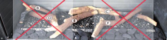
12 M ETRO 70 - INSTRUCTION FOR INSTALLATION Photo 9a Photo 9b Foto 10a Damper (R) The damper (R) is packed separately. This is fi tted as follows (see Fig. 6): Foto 10b Unscrew the 6 self-tapping screws in the centre plate. Remove this plate. Fit the damper. Adjust the distance of the damper using the template provided (see Fig. 7): a distance of 33 mm means that the damper is closed as far as possible; use the template to adjust to 38, 43, 48 and 53 mm. Secure the damper in place with the socket-head screw. Replace the centre plate Air inlet guides (L) The air inlet guides (L) rest left and right on the sides of the burner tray, see Fig. 8. Remove the air inlet guides if necessary. 6.9 Arranging the logs / pebbles The appliance is supplied with a set of logs or pebbles. Observe the instructions below precisely to avoid unsafe situations. - only use the log/pebble set supplied; - arrange the logs/pebbles exactly as described; - make sure the pilot burner and the space around it are kept free from objects (see Photos 9a and 9b); - make sure that thermocouple 2 and the space around it are kept free from objects (see Photos 10a and 10b); - make sure that the slot between the burner tray and the tray surrounding the burner is kept free from objects Logs The log set consists of vermiculite (see Photo 2), chippings (see Photo 3) and a few branches. Fill the burner tray with the vermiculite, spreading it out evenly. - You can alter the flame effect by moving the vermiculite but - the burner cap must remain covered by vermiculite to help preserve the useful life of the burner. Fill the tray surrounding the burner with chippings; spreading them out evenly. Identify the braches A-F using Photo 4 for reference.!tip The burn marks on the branches will help you identify them. Arrange branches A-C around the (main) burner (see Photos 5 and 6): - First lay branch A symmetrically with respect to the pilot burner; - Continue with branches B and C. UK 12
 because: - the main burner will then not ignite properly, which could lead to unsafe situations; - soot will accumulate")
.")
13 Photo 11 Photo 12 Photo 13 Now lay branches D, E and F (see Photo 7). The branches must not cover the burner cap entirely (see Photos 5 and 8) because: - the main burner will then not ignite properly, which could lead to unsafe situations; - soot will accumulate faster; - the flame effect will be distorted Pebbles The set of pebbles consists of natural coloured vermiculite (see Photo 2) and white carrara stones. Fill the burner tray with the vermiculite, spreading it out evenly (see Photo 11). - You can alter the flame effect by moving the vermiculite but - the burner cap must remain covered by vermiculite to help preserve the useful life of the burner. Fill the burner tray and the tray surrounding the burner with the carrara stones. Spread them evenly in a single layer; see Photos 12 and 13. If pebbles on top of each other or otherwise wrongly arranged this could result in: - the main burner not igniting properly, which could lead to unsafe situations; - the flame effect will be distorted. 13 UK


14 Foto 14a Foto 17a Foto 17b Foto 14b Foto 17c Foto 17d Foto 15 Foto 16 Foto 17e Foto 17f UK 14


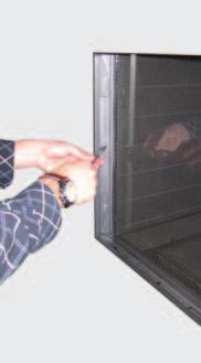
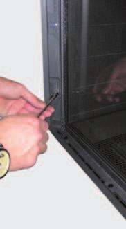
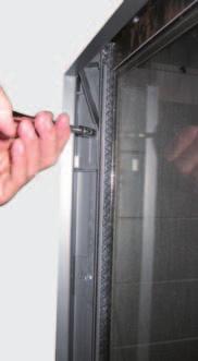
15 Foto 18 Foto Glass window Once the logs have been arranged the glass window can be fi tted as described below Removing the glass window Remove the glass frame in accordance with the following instructions (see Photos 14 to 19): Remove the vertical decorative strips on the left and right of the glass frame by pushing the lip at the top of each strip up, tilting the top of the strip parallel with the glass frame, and then removing the strip. Remove the horizontal decorative strip by gripping it with 2 hands in the slot and lifting it out. Unscrew the 4 self-tapping screws in the bottom strip using the socket spanner supplied with the appliance. Loosen the 3 self-tapping screws in the fastening strips on both sides 2 turns. Do not remove the self-tapping screws: leave them in place in the fastening strips. Push the 2 top wedges (left and right) down as far as possible. Push the 2 bottom wedges upwards as far as possible. Press the two fastening strips outwards with your hands as far as possible to avoid damage to the sealing cord. Take hold of the top and bottom handgrips and lift the glass frame. Pull on the bottom handgrip to tilt the glass frame in its mounting towards you and, at the same time, pull the top of the glass frame towards you as far as possible. - Make sure you hold the upper handgrip firmly. If you let go of the handgrip then the glass frame could fall inwards and cause severe damage to both the glass and the appliance; - Make sure that you lift the glass frame out of its mounting as straight as possible to avoid damage to the paintwork and the sealing cord. Gently allow the glass frame to drop at an angle until it can be removed entirely from the mounting. 15 UK
16 Fitting the glass window The glass frame is fi tted by using the above procedure, in reverse order. - Avoid/remove fingerprints on the glass, since otherwise they will burn into the surface; - The self-tapping screws must not be over-tightened, since otherwise they could break or strip the thread: tight=tight; - Replace the fastening strip if the sealing cord has come loose.!tip Pay attention to the following when fi tting the glass frame: Begin by checking that the two fastening strips are pressed outwards as far as possible to avoid damage to the sealing cord. Fit the glass frame. Check that the hook at the top of the glass frame is in position in the seating / U-shaped strip. Pull on the upper handgrip to move the glass frame towards you: if it does not move, then it has been fitted correctly. Fix the glass frame s bottom strip in place with the 4 self-tapping screws. Push both bottom wedges downwards. Push the top wedges upwards until the sealing cord of both fastening strips press against the glass. Tighten each wedge s self-tapping screw. Press on the wedge with your hand to hold it in place while you tighten the screws. Tighten the middle self-tapping screw in each fastening strip. Fit the horizontal decorative strips. Fit the vertical decorative strips. 7. Wireless remote control See Chapter 4 of the User Manual, Remote Control, for details of how to operate the system. The remote system consists of a remote control system and a receiver. The procedure for connecting the receiver has been described below; the working of the remote control system has been explained in detail in Chapter 4, 4.2 of the User Manual 4, Receiver The receiver should be connected to the appliance, before the batteries are installed. Follow the procedure below (see Photo 21): Fit the connection cable s brown plug to the receiver (see Photo 21, arrow F). Connect the white plug to the gas control.!tip The plugs have different sizes that correspond with the connectors. Connect the cables of thermocouple 1 to the receiver; (see Photo 21, arrows B).!Tip - The size of the eye corresponds with the size of the screw; - The colours of eye and screw also correspond. Connect the black wire with the white plug of thermocouple 2 to the receiver (see Photo 21, arrow E). Make sure that the wires of thermocouple 2 cannot come into contact with hot parts Connect the ignition wire to the receiver (see Photo 21, arrow A) Connect the power supply: a) For batteries see section below; b) For an adapter: - connect the adapter to the receiver (see Photo 21, arrow C) - plug the adapter into the wall socket. Place the receiver in the control box: - Position the receiver as shown in Photo 22 Bend the aerial out of the clips, see Photo 21, arrow D. Put the aerial straight up. UK 16

 batteries. - Avoid short circuits between the batteries and metal objects/components.")
17 Photo 21 Photo 22 - Do not put the aerial too close to the ignition wire and/or metal parts (see Photo 22 for the correct position) - Do not lay the ignition wire across and/or beside metal parts: this will weaken the spark. - Do not lay the ignition wire across the receiver: this could damage the receiver. - Avoid dust accumulating on or in the receiver: cover it during servicing or maintenance Fitting/replacing the batteries To fi t the batteries: Open the flap on the control box. Take the receiver. Slide the lid off. Fit or remove the 4 penlight (AA size) batteries. - Avoid short circuits between the batteries and metal objects/components. - Note the + and - positions of the batteries in the holder. - Use alkaline batteries. Slide the lid back on. Replace the receiver. Do not throw batteries in the dustbin, they are considered domestic chemical waste and should be disposed of accordingly. 8. Final inspection To ensure the appliance is working correctly and safely, check the following before use: 8.1 Gastightness All connections must be gastight. The maximum pressure to which the gas control block may be exposed is 50 mbar. Test the connections for gastightness. 8.2 Gas pressure/pre-pressure The burner pressure is factory adjusted; see type plate. It is not necessary to check the burner pressure. The pre-pressure in house installations should be checked, as they can vary. Check the pre-pressure; see Appendix 2 /Table 5 and Photo 24 for the measuring nipple on the gas control. Contact the gas company if the pre-pressure is not correct. 17 UK


18 Photo 23 Photo 24 Photo Igniting the pilot and main burner Pilot Test that the pilot ignites properly, see Operating Instructions, section 4.2 Remote control: - the pilot burner should ignite at the first attempt. If the pilot does not light, then Check whether or not the ignition sparks: a) If not, the ignition wire is probably touching something metal; b) If it does, there is probably air in the pipes. Bleed off any air in the pipes and/or Move the ignition wire so that it does not touch anything metal.!tip Main burner The burner should ignite evenly and should not pop as a result of delayed ignition. Test the working of the main burner from stand-by (pilot) mode; see Operating Instructions, section 4.2 Remote control. once the gas valve has opened the main burner should ignite within a few seconds. When the gas valve opens the motor will start to run; this is audible. 1) If the main burner does not ignite, then: Check that button A on the gas control block is set to ON; Check that the space round the pilot is free; Check that the logs/pebbles have been arranged correctly. Resolve any of the above as necessary. Test the main burner 5 times to ensure it is working properly. 2) If the main burner ignites, but goes out again after approx. 22 seconds, please: Check the wiring of thermocouple 2 for: - Loose wiring; - Wrongly connected wiring; - Short-circuit; - Broken wire. Check if thermocouple 2 is dirty. Check if thermocouple 2 is positioned correctly in the flame; see Photo 26. Check if thermocouple 2 is defective; see chapter 11, table 4 under J7. Check if the receiver is defective; see chapter 11, table 4 under J8. If necessary, correct the above mentioned faults. Test the main burner 5x for a good operation. 8.4 Flame effect The flame effect cannot really be assessed until the fi re has been on for several hours. Volatile elements in paint, materials, etc., which evaporate during the fi rst hours of use, will initially influence the flame effect. If the chimney breast is made of stone-like materials or has been finished in stucco, it should be left to dry for at least 6 weeks prior to taking it into operation, in order to prevent cracks. Check that the flame effect is symmetrical. An asymmetrical flame effect could be caused by: - volatile substances evaporating; - incorrectly arranged logs/pebbles. Rearrange the logs/pebbles as necessary. UK 18

19 9. Maintenance The appliance should be inspected, cleaned and if necessary repaired by a qualifi ed installer with professional experience of decorative gas fi res at least once a year. The appliance should at least be tested to check it works correctly and safely. - Close the gas tap when performing maintenance work; - Check the gastightness after repair; - After replacing thermocouple 1 you should first tighten the swivel by hand and then give it another quarter turn with a suitable spanner. Clean the following components if necessary: - the pilot burner; - the space surrounding the pilot burner; - the thermocouple 2 - the glass - Remove the glass as described in section Remove the deposit on the inside of the glass with a damp cloth or a non-abrasive cleaning product such as copper polish; - Avoid/remove fingerprints on the window as they will burn into the glass; - Replace broken and/or cracked glass. - Replace the logs/pebbles correctly; see section 6.9. Inspect the flue / combustion air supply system. Test the system as described in chapter Completion Familiarise the user with the appliance. You should instruct him/her on such things as how to use the appliance and how it works, how to use the remote control, and about the need for annual maintenance. - Tell the user to switch off the gas immediately and to contact the installer in the event of a failure / malfunction, to avoid unsafe situations; - Show him/her where the gas tap is. Explain how to use the appliance and the remote control. Point out that when the appliance is used for the first time: - If the chimney breast is made of stone-like materials or has been finished in stucco, it should be left to dry for at least 6 weeks prior to taking it into operation, in order to prevent cracks - volatile elements in paint, materials etc. will evaporate the first time the fire is used; - the fire should preferably be used at the highest setting so that these elements will evaporate more quickly; - the room should be well ventilated. Hand the user the user manual and the installation manual (the installation manual should be kept near the appliance). Photo UK
20 11. Troubleshooting A number of faults which could occur, their possible causes and solutions are shown in the table below: Table 3: Troubleshooting Problem Possible cause Remedy A. No transmission (motor will not run) 1. The (new) communication code between receiver and remote control must still be confi rmed. 2. Empty batteries. 3. Receiver is damaged. 4. Remote control is damaged. 5. Motor cable at valve/receiver is broken. 6. Bent pins of the 8-wire connector. 7. If the receiver is surrounded by metal, this could decrease the transmission range. B. No ignition (spark) 1. Button A in position MAN. 2. Ignition cable runs over and/ or alongside metal parts. 3. Ignition pen corroded second delay before the full restart is not yet fi nished. C. No sound signal 1. Receiver is damaged. D. One continuous sound signal of 5 sec. (Possible 7 short beeps prior to the 5 sec. sound signal) second delay before the full restart is not yet fi nished. 1. Loose wiring between receiver and gas control. 2. Receiver is damaged. 3. Bent pins of the 8-wire connector. 4. Damaged magnetic valve. 5. Thermocouple 2 still too hot. 1. Hold down the reset button of the receiver, until you hear 2 sound signals; see Photo 23. Let go of the reset button after the second, longer sound signal and press button (small flame) or button (large flame) on the remote control within 20 sec., until you hear an extra long sound signal confi rming that the new code has been set. 2. Replace batteries.!caution Avoid short circuit between the batteries and metal parts of the appliance. 3. Replace the receiver and confi rm the code (remedy 1). 4. Replace the remote control and confi rm the code (remedy 1). 5. Replace the motor cable. 6. Make sure that the pins of the 8-wire connector are straight. 7. Change the position of the antenna. 1. Switch button A on the gas control to ON, see Photo Do not place the ignition cable (S) over and/or along metal parts. This will weaken the spark; see Photo 22. If necessary, replace the ignition cable. 3. Replace the ignition pen. 4. Wait until the delay time has passed. 1. Replace the receiver and confi rm the code (remedy 1 at A) 2. Wait until the delay time has passed. 1. Connect the wiring properly. 2. Replace the receiver and confi rm the code (remedy 1 at A) 3. Make sure that the pins of the 8-wire connector are straight. 4. Replace the gas control. 5. Wait until the thermocouple has cooled down suffi ciently UK 20
21 Table 3: Troubleshooting Problem Possible cause Remedy E. No pilot burner flame 1. Air in the pilot burner pipe. F. Electronics keep sparking while the pilot burner is ignited G. Pilot burner is burning, but magnetic valve closes after ca. 10 seconds or when the appliance gets hot H. There are short sound signals, but no sparks and no sound / clicks can be heard of the magnet opening the valve I. Pilot burner is burning, but there is no gas flow to the main burner 2. Wires of thermocouple 1 have been cross-connected. 3. No spark at the pilot burner. 4. Injector is blocked up. 1. Flush the pipe or start the ignition process several times. 2. Check the polarity of the thermocouple wiring. Connect the thermocouple wiring properly, if necessary. 3.1 Check if the ignition cable (S) is lying free from metal parts; see Photo 22. If necessary, move it away from the metal parts. 3.2 If necessary, replace the ignition cable. 3.3 If necessary, replace the ignition pen. 4.1 Clean the injector. 4.2 If necessary, replace the injector. 1. Receiver is damaged. 1. Replace the receiver and confi rm the code (remedy 1 at A) 1. Thermocouple 1 does not function. 2. Batteries (almost) empty. 1.1 Measure the voltage, using a digital multimeter, set to mv range, by connecting the cables to the cable shoe. The cable shoe is located on the outside, directly next to the magnet nut at the rear of the gas control; see Photo 25. The voltage should be at least 5mV within 20 seconds. It may not be lower when the appliance is warm. If the voltage is too low: - the thermocouple should be placed better in the flame or - the thermocouple should be replaced. 1.2 Check the size of the pilot burner flame. Correct a flame that is too small. 1.3 Check the wiring of the thermocouple to the receiver. If necessary, replace the wiring. 2. Replace the receiver s batteries.!caution Avoid short circuit between the batteries and metal parts of the appliance. 1. Batteries (almost) empty. 1. Replace the receiver s batteries.!caution Avoid short circuit between the batteries and metal parts of the appliance. 1. Button A in position MAN. 2. Appliance in the pilot flame position. 3. Pre-pressure of the gas is too low. 4. Damaged magnetic valve. 1. Turn button A on the gas control to ON; see Photo Increase the flame height by pressing button (large flame) on the remote control. 3. Check pre-pressure. If necessary, contact gas company. 4. Replace the gas control. 21 UK
22 Table 3: Troubleshooting Problem Possible cause Remedy J. Main burner ignites, but goes out again after approx. 22 seconds 1. Wiring of thermocouple 2 is loose. 2. Wires of thermocouple 2 have been cross-connected. 3. Short-circuit in the wiring of thermocouple Broken wire in the wiring of thermocouple Thermocouple 2 is dirty. 6. Thermocouple 2 is not positioned correctly in the flame (see Photo 26.) 7. Thermocouple 2 is defective. 8. Receiver is defective. 1. Connect the wiring properly. 2. Connect the wiring properly. 3. Replace wiring. 4. Replace wiring. 5. Clean the thermocouple. 6. Position the thermocouple correctly in the flame. 7. Check the voltage across thermocouple 2 just before the main burner goes out. If the voltage is lower than 1.8 mv, replace thermocouple Check the voltage across thermocouple 2 just before the main burner goes out. If the voltage is higher than 1.8 mv, replace the receiver. UK 22
23 Annex 1 Components supplied The table below specifi es the components supplied with the appliance. Table 4: Components supplied Component Quantity Order number Set of Logs/Pebbles 1x / Control box 1x Control box manual 1x Installation manual 1x User manual 1x Trim left/right Metro 70 2x Metro 70 Tunnel 4x Trim bottom Metro 70 1x Metro 70 Tunnel 2x Damper template 1x Damper 1x Rawplugs M8x140x50 2x Hexagonal nut M8 4x Washer 8.4 mm 4x Spare self-tapping screws for the glass window Socket spanner 8 mm 1x Remote control with receiver 1x V square battery 1x Penlight battery (AA type) 4x Pressure coupling 15 mm x G3/8 1x Annex 2 Technical data The technical data for the Metro 70/ Metro 70 Tunnel are given in the table below. Table 5: Technical data Type C11/C31 Pre-pressure (mbar) Gas type G31 G31 Burner pressure mbar 28.5 NL 30 Nominal Load (Hs) kw 6.6 BE 37 Nominal Load (Hi) kw 6.0 FR 37 Nominal Capacity kw 4.3 DE 50 Consumption L/h 245 AT 50 Burner jet mm 2x Ø 0.95 CH 37 Consumption on stand-by L/h 163 GB 37 Fine adjustment jet mm Ø 1.20 IE 37 Pilot jet Code 30 NO 30 Effi ciency category 2 PT 37 Annex 3 Spare parts Spare parts are available from 23 UK
24 M ETRO 70 - INSTRUCTION FOR INSTALLATION UK DRU Verwarming BV The Netherlands Postbus 1021, NL-6920 BA Duiven Ratio 8, NL-6921 RW Duiven UK
PowerVent. Installation manual (GB) English. Store this document in a safe place UK
 English. Store this document in a safe place UK") PowerVent Installation manual (GB) Store this document in a safe place 959.034.03.UK GB Contents Blz Foreword 3 1. Introduction 3 2. CE declaration 4 3. SAFETY 4 3.1 General 4 3.2 Regulations 4 3.3 Precautions
PowerVent Installation manual (GB) Store this document in a safe place 959.034.03.UK GB Contents Blz Foreword 3 1. Introduction 3 2. CE declaration 4 3. SAFETY 4 3.1 General 4 3.2 Regulations 4 3.3 Precautions
PowerVent. Installation manual (GB) English. Store this document in a safe place UK
 English. Store this document in a safe place UK") PowerVent Installation manual (GB) Store this document in a safe place 959.078.00.UK GB Contents page Foreword 3 1. Introduction 3 2. CE declaration 4 3. SAFETY 4 3.1 General 4 3.2 Regulations 4 3.3 Precautions
PowerVent Installation manual (GB) Store this document in a safe place 959.078.00.UK GB Contents page Foreword 3 1. Introduction 3 2. CE declaration 4 3. SAFETY 4 3.1 General 4 3.2 Regulations 4 3.3 Precautions
User manual (GB / IE) for appliances provided with an electronic ignition on the remote control. English. Read this document and store it carefully
 for appliances provided with an electronic ignition on the remote control. English. Read this document and store it carefully") User manual (GB / IE) for appliances provided with an electronic ignition on the remote control Read this document and store it carefully 958.007.07.uk 1 UK Contents page Preface 2 1. Introduction 3 2.
User manual (GB / IE) for appliances provided with an electronic ignition on the remote control Read this document and store it carefully 958.007.07.uk 1 UK Contents page Preface 2 1. Introduction 3 2.
Clear Installation guide
 Clear 40010631-0938 ENG Installation guide ENG 1.1 1.2 1.3 A 1.4 1.5 1 < < < < A B 2.1 2.2 2.3 C 2.4 2.5 2 < < < < 3.1 3.2 3-3 3 < < < < Inhoudsopgave 1 Introduction... 6 2 Safety instructions... 6 3 Installation
PowerVent Installation manual. English. Store this document in a safe place EN
 PowerVent - 02 Installation manual Store this document in a safe place 959.114.01.EN en Contents Page Foreword 3 1. Introduction 3 2. CE declaration 4 3. SAFETY 4 3.1 General 4 3.2 Regulations 4 3.3 Precautions
Fyn Installation guide
 Fyn 600 4001131-1123 ENG Installation guide ENG 1.1 1.2 A B 1.3 1.4 1 < < < < 2.1 2.2 2.3 2.4 3.1 3.2 2 < < < < 4.1 4.2 4.3 4.4 3 < < < < 1 Introduction The appliance can only be installed by a competent
Trio RCE. G20/G25/G25.3 (natural gas) Instructions for installation. English. Please retain this document carefully EN
 Instructions for installation. English. Please retain this document carefully EN") Trio RCE G20/G25/G25.3 (natural gas) Instructions for installation Please retain this document carefully 959.064.04.EN EN Contents page Preface 2 1. Introduction 3 2. CE Declaration 3 3. SAFETY 3 3.1 General
Trio RCE G20/G25/G25.3 (natural gas) Instructions for installation Please retain this document carefully 959.064.04.EN EN Contents page Preface 2 1. Introduction 3 2. CE Declaration 3 3. SAFETY 3 3.1 General
Duet XL /0929. Installation guide
 Duet XL 40010749/0929 ENG Installation guide ENG 1.1 1.2 1.3 1.4 1.5 A 1.6 1.7 1 < < < < B A 2.1 2.2 2.3 2.4 2 < < < < 2.5 2.6 2.7 2.8 3 < < < < 3.1 F F 3.2 3.3 4 < < < < Table of contents 1 Introduction...
Fyn Installation guide
 Fyn 450 400100929-1114 ENG Installation guide ENG 1.1 1.2 A B 1.3 1.4 1 < < < < 2.1 2.2 2.3 3.1 3.2 2 < < < < 4.1 4.2 4.3 4.4 3 < < < < Table of contents 1 Introduction... 6 2 Safety instructions... 6
Solution Installation guide
 Solution 40011444-1327 ENG Installation guide ENG 1-1 1-2 1-3 1.4 1 < < < < 2.1 2-3 2-4 2 < < < < 3-1 3.2 3-3 3.5 3.6 3 < < < < 4-1 A 4-2 4-3 4 < < < < Dimensions Terminal position Distance (For good working
FLAME HEATER PYRAMID CLFH-10SS OPERATION INSTRUCTIONS
 FLAME HEATER PYRAMID CLFH-10SS OPERATION INSTRUCTIONS www.colorato.net For outdoors use only Uses propane, butane or LPG only Reflector: 47x47 mm Total Height: 2250 mm Regulator s external pressure: 28-30
Circo RCE G20/G25/G25.3/G31. Installation manual. English. Store this document in a safe place DRU EN-US
 irco RE G20/G25/G25.3/G31 Installation manual Store this document in a safe place 959.044.02.UK DRU-175417-EN-US-1017-4 EN INSTLLTION MNUL ontents 1. Introduction 2. E declaration 3. SFETY 3.1 General
Respect OC Installation manual
 Respect OC 40011335-1235 ENG Installation manual ENG 1.1 1.2 A 1.3 1.4 A A 2.1 2.2 2.3 1 < < < < 2.4 2.5 B C A B A 2.6 2 < < < < 3.1 3.2 3.3 3.4 3.5 3.6 3 < < < < A B 3.7 4 < < < < L A A 4.1 A A 4.2 A
VASKA C11. gas -fireplace installation guide
 VASKA C11 gas -fireplace installation guide Saturnus 8 NL-8448 CC Heerenveen Postbus 219 NL-8440 AE Heerenveen T. +31(0)513 656500 F. +31(0)513 656501 40 010 459 01 51 DESCRIPTION OF THE FIREPLACE CONTENTS
Metro 130XT 41 RCH Metro 130XT Tunnel 41 RCH
 Metro 130XT 41 RH Metro 130XT Tunnel 41 RH G20/G25/G25.3 (Natural gas) G31 (Propane) Installation manual Store this document in a safe place 959.073.02.EN DRU-667777-EN-US-1017-3 EN ontents 1. Introduction
Metro 130 XT Metro 130 XT Tunnel
 Metro 130 XT Metro 130 XT Tunnel G20/G25/G31 Installation manual (G/IE) Store this document in a safe place 959.041.00. DRU15798-112731-EN--0113-2 INSTLLTION MNUL ontents 1. Introduction 2. E declaration
Duet Premium M Duet Premium M ENG
 Duet Premium M 40011422-1441 Duet Premium M ENG 1.1 1.2 1.3 1.4 1.5 1.6 1.7 1.8 1 < < < < 2.1 a 2.1 b 2.1 c A C 2.2 2 < < < < F F 2.3 X H X C 2.4 2.5 S T 3.1 3.2 R Q 3.3 3 < < < < 4.1 4.2 4.3 4.4 4 <
Vaska Logburner. voorbeeld Installation guide
 Vaska ogburner voorbeeld 40010627-2103 ENG Installation guide ENG 1.1 1.2 1.3 1.4 1.5 1 < < < < 1 Introduction The appliance can only be installed by a competent person in accordance with the Gas Safety.
Relaxed Premium M Relaxed Premium M ENG
 Relaxed Premium M 40010959 1440 Relaxed Premium M ENG 3 alternative finishes. 1.1a 1.1b 1.1c 1 < < < < 1.2 1.3 7 1.4 2 < < < < 1.5 1.6 B 1.9 3 < < < < 2.1 2.2 2.3 3.1 3.2 3.3 3.4 4 < < < < 3.5 4.1 4.2
User Guide Compact-7 series
 User Guide Compact-7 series Boiler-CH Calorifier Combi Introductory remarks Congratulations on the purchase of your Kabola Compact 7. Kabola has been a manufacturer of oil-fired heating systems since 1947.
Circo G20/G25/G31. Installation manual (GB/IE) English. Store this document in a safe place DRU EN
 English. Store this document in a safe place DRU EN") irco G20/G25/G31 Installation manual (G/IE) Store this document in a safe place 959.044.01. DRU15798-175417-EN--0213-2 INSTLLTION MNUL ontents 1. Introduction 2. E declaration 3. SFETY 3.1 General 3.2
irco G20/G25/G31 Installation manual (G/IE) Store this document in a safe place 959.044.01. DRU15798-175417-EN--0213-2 INSTLLTION MNUL ontents 1. Introduction 2. E declaration 3. SFETY 3.1 General 3.2
Imperial Electric Fires
 Imperial Electric Fires GB IE MODELS: Flamescape II Curvascape II manual & remote. Installation and User Instructions PLEASE READ THESE INSTRUCTIONS CAREFULLY AND RETAIN FOR FUTURE REFERENCE This electric
Propane Heater REMKO PGM 30 REMKO PGM 60
 Propane Heater REMKO PGM 30 REMKO PGM 60 Operation Technology Spare Parts Edition GB L07 REMKO strong as a bear. Operating instructions Make sure to read these instructions carefully before starting/using
Duet Premium L Duet Premium L ENG
 Duet Premium L 40011297-1441 Duet Premium L ENG 1.1 1.2 1.3 1.4 1.5 1.6 1.7 1.8 1 < < < < 2.1 a 2.1 b 2.1 c A C 2.2 2 < < < < F F 2.3 X H X C 2.4 2.5 S T 3.1 3.2 R Q 3.3 3 < < < < 4.1 4.2 4.3 4.4 4 <
Paco RCH. G20/G25/G25.3 Natural gas. Installation manual (UK/IE) English. Store this document in a safe place DRU EN-US
 English. Store this document in a safe place DRU EN-US") Paco RH G20/G25/G25.3 Natural gas Installation manual (/IE) Store this document in a safe place 959.098.01. DRU-680093-EN-US-0916-2 ontents 1. Introduction 2. E declaration 3. SFETY 3.1 General 3.2 Regulations
Paco RH G20/G25/G25.3 Natural gas Installation manual (/IE) Store this document in a safe place 959.098.01. DRU-680093-EN-US-0916-2 ontents 1. Introduction 2. E declaration 3. SFETY 3.1 General 3.2 Regulations
Servicing manual. Wall-mounted condensing gas boiler 600 Series - 11S / 19S / 24S / 24C /2002 GB(EN) For trade use
 For trade use") GB122 7210 1300-12/2002 GB(EN) For trade use Servicing manual Wall-mounted condensing gas boiler 600 Series - 11S / 19S / 24S / 24C Please read thoroughly before attempting to diagnose fault List of contents
GB122 7210 1300-12/2002 GB(EN) For trade use Servicing manual Wall-mounted condensing gas boiler 600 Series - 11S / 19S / 24S / 24C Please read thoroughly before attempting to diagnose fault List of contents
Servicing manual. 600 Series - 11S / 19S / 24S / 24C. Wall-mounted condensing gas boiler. For trade use
 GB122 Servicing manual Wall-mounted condensing gas boiler 600 Series - 11S / 19S / 24S / 24C For trade use Please read thoroughly before attemting to diagnose fault 7217 4900 (03/2010) GB/IE List of contents
HG 675 CX 60 HG 675 CN 60 HG 675 CW 60
 HG 675 X 60 HG 675 CX 60 HG 675 CN 60 HG 675 CW 60 1 2 1. : 93/68: 90/396: 2006/95/CE: 2004/108/CE: - 1935/2004:. 2002/95/CE: RoHS 2.,.,,,,...,. (,..)..,,.,. ( ),,, ;,,.,.....,.,,,,,,...,. (..),,.,..,.,,,,
VASKA B11. gas -fireplace installation guide
 VASKA B11 gas -fireplace installation guide Saturnus 8 NL-8448 CC Heerenveen Postbus 219 NL-8440 AE Heerenveen T. +31(0)513 656500 F. +31(0)513 656501 40 010 446 01 51 DESCRIPTION OF THE FIREPLACE CONTENTS
Installation Manual EF5000 AUS & NZ
 Installation Manual EF5000 AUS & NZ This manual is ONLY for fires with a serial No. from 80600 to 80999. Important: The appliance shall be installed in accordance with; Local gas fitting regulations Municipal
JUNEAU JUN. 08/51193/0 Issue 0
 JUNEAU JUN 08/51193/0 Issue 0 The product complies with the European Safety Standards EN60335-2-30 and the European Standard Electromagnetic Compatibility (EMC) EN55014, EN60555-2 and EN60555-3 These cover
Installation and maintenance instructions
 6304 4995 0/004 GB For installer Installation and maintenance instructions Flue gas heat exchanger WT50/60 Please read thoroughly prior to installation and maintenance. Summary About this manual This equipment
IDE 20 / IDE 30 / IDE 50 IDE 60 / IDE 80
 IDE 20 / IDE 30 / IDE 50 IDE 60 / IDE 80 EN OPERATING MANUAL OIL HEATER TRT-BA-IDE20-30-50-60-80-TC-001-EN Table of contents Information on the use of this manual... 1 Scope of delivery... 1 General safety...
F900 SERIES GAS CHARGRILL G9440, G9460, G9490, G User, installation and servicing instructions T Read these instructions before use
 F900 SERIES User, installation and servicing instructions GAS CHARGRILL G9440, G9460, G9490, G94120 Read these instructions before use DATE PURCHASED: MODEL NUMBER: SERIAL NUMBER: DEALER: SERVICE PROVIDER:
LUNA 850 V GOLD GAS INSTRUCTION FOR INSTALLATION AND USE. Passion for fire
 LUNA 850 V GOLD GAS INSTRUCTION FOR INSTALLATION AND USE Passion for fire SUMMARY 1. GENERAL REMARKS...3 2. CONNECTION...3 3. SPECIFICATION SHEET...4 4. ASSEMBLY OF THE CHIMNEY...5-7 5. ELECTRICAL CONNECTION...8
INSTALLATION AND OPERATION INSTRUCTIONS FOR
 INSTALLATION AND OPERATION INSTRUCTIONS FOR BI-40-DEEP-XT BI-50-DEEP-XT BI-60-DEEP-XT BI-72-DEEP-XT BI-88-DEEP-XT SAFETY INFORMATION WARNING If the information in these instructions are not followed exactly,
Gas Instantaneous Water Heater
 6 720 607 823 GB (06.06) SM Installation and Operating Instructions Gas Instantaneous Water Heater WR10..B... WR11..B... With electronic ignition and triple safety system consisting of ionisation detector,
Torch framed Installation Guide
 Torch framed 40010567-0602 Installation Guide 1 2 3 4 1 < < < < 5 6 7 > > > > 2 Content 1 Introduction... 1 2 Safety Instructions... 2 3 Installation requirements... 3 3.1 Rear surface construction...
INSTALLATION AND OPERATION INSTRUCTIONS FOR ZERO CLEARANCE AND INSERT UNITS
 INSTALLATION AND OPERATION INSTRUCTIONS FOR ZERO CLEARANCE AND INSERT UNITS ZECL-26-2923-BG ZECL-30-3226-BG ZECL-33-3624-BG ZECL-39-4134-BG ZECL-2939-BG INSERT-26-3825-BG INSERT-30-4026-BG INSERT-33-4230-BG
VIEW BELL SMALL 3 CF/LF
 INSTALLATION INSTRUCTIONS & MANUAL FOR MAINTENANCE VIEW BELL SMALL 3 CF/LF Gas fi res with closed combustion system Bellfi res wishes you many cosy evenings with your new Bellfi res gas fi re This document
INSTALLATION INSTRUCTIONS & MANUAL FOR MAINTENANCE DERBY LARGE 3 CF/LF. Gas fi re with closed combustion system
 INSTALLATION INSTRUCTIONS & MANUAL FOR MAINTENANCE DERBY LARGE 3 CF/LF Gas fi re with closed combustion system Bellfi res wishes you many cosy evenings with your new Bellfi res gas fi re This document
900 Quadrant Steam Shower Cabin with 6 Body Jets
 Product Specification Working Pressure 1.5 to 4 bar Pressure MUST be balanced Dimensions 2250 H x 900 D x 900 W Door Opening 480mm Steam Generator 2.8Kw Fuse size: 13 amp fuse spur 900 Quadrant Steam Shower
Gas Fire Patio Heater Q9
 Gas Fire Patio Heater Q9 Instruction Manual Please read the manual BEFORE you unpack or install the fire TABLE OF CONTENTS Warning 3 Getting Started 4 What s Included 5 Assembly Procedures 6 Product Drawing
Proline GAS HOB Model TCG40IX Instruction Book
 Proline GAS HOB Model TCG40IX Instruction Book GB Operating and Installation Instructions Index Technical data and specifications...... 3 Installation...................... 3-6 Ventilation........................
CRYSTAL FIRES. Inset Conventional Flue Fire. (BOSTON/MIAMI) Cf1 and MANHATTAN USER INSTALLATION AND SERVICING INSTRUCTIONS
 Cf1 and MANHATTAN USER INSTALLATION AND SERVICING INSTRUCTIONS") CRYSTAL FIRES (BOSTON/MIAMI) Cf1 and MANHATTAN Inset Conventional Flue Fire USER INSTALLATION AND SERVICING INSTRUCTIONS FOR USE WITH NATURAL GAS G20 @ 20 mbar For use in GB and IE CE THESE INSTRUCTIONS
CRYSTAL FIRES (BOSTON/MIAMI) Cf1 and MANHATTAN Inset Conventional Flue Fire USER INSTALLATION AND SERVICING INSTRUCTIONS FOR USE WITH NATURAL GAS G20 @ 20 mbar For use in GB and IE CE THESE INSTRUCTIONS
USHO COOKER INSTALLATION INSTRUCTIONS SAFETY INSTRUCTIONS USER INSTRUCTIONS MODEL: USHO. INSTRUCTION REF: IN152 ISSUE No. 4 DATE
 Page 1 of 11 INSTALLATION INSTRUCTIONS SAFETY INSTRUCTIONS USER INSTRUCTIONS USHO COOKER MODEL: USHO Page 2 of 11 WARNING To avoid scratching the highly polished exterior surface of this equipment whilst
Maestro 80-2 RCH Maestro 80-3 RCH
 Maestro 80-2 RH Maestro 80-3 RH G20/G25/G25.3 (Natural gas) G31 (Propane) Installation manual (/IE) Store this document in a safe place 959.094.04. DRU-677279-EN-US-1016-5 INSTLLTION MNUL ontents 1. Introduction
Installation and maintenance instructions
 6304 4994 03/2006 GB For installer Installation and maintenance instructions Flue gas heat exchanger WT30/40 Please read thoroughly prior to installation and maintenance. Contents Contents Contents 2 1
Remeha. Fuel oil/gas boilers P 520. Installation and Service Manual A
 Remeha Fuel oil/gas boilers EN Installation and Service Manual 300016859-001-A 63115 Declaration of conformity The appliance complies with the standard model described in declaration of compliance. It
Charlotte CRT20AB, Charlotte CRT20BR & Brookline BKL20
 Charlotte CRT20AB, Charlotte CRT20BR & Brookline BKL20 08/51007/0 Issue 1 The product complies with the European Safety Standards EN60335-2-30 and the European Standard Electromagnetic Compatibility (EMC)
COMMERCIAL GAS AND ELECTRIC STACKED WASHER/ DRYER INSTALLATION INSTRUCTIONS
 COMMERCIAL GAS AND ELECTRIC STACKED WASHER/ DRYER INSTALLATION INSTRUCTIONS MODELS MLG19PD, MLE19PD The installation, including a proper exhaust system, is the responsibility of the owner. LEAVE THESE
U S E R M A N U A L. Kabola Compact. Kabola Heating Systems BV Placotiweg 1E 4131 NL Vianen The Netherlands
 U S E R M A N U A L Kabola Compact Kabola Heating Systems BV Placotiweg 1E 4131 NL Vianen The Netherlands www.kabola.nl Preface Congratulations on the purchase of your new Kabola Compact boiler. It s the
Built-in Gas Hob CZ55554 CZ55571
 Built-in Gas Hob CZ55554 CZ55571 INSTALLATION AND OPERATING INSTRUCTIONS The product may differ from the one illustrated but the installation and operation procedure remains the same The product may differ
52 CEILING FAN READ AND SAVE THESE INSTRUCTIONS FAN RATING AC 120V.
 Irene 52 CEILING FAN READ AND SAVE THESE INSTRUCTIONS FAN RATING AC 120V. 60Hz TABLE OF CONTENTS Tools and Materials Required... 1 Package Contents... 1 Safety Rules... 2 Mounting Options... 3 Hanging
INSTALLATION AND OPERATION INSTRUCTIONS FOR BI-DEEP UNITS
 INSTALLATION AND OPERATION INSTRUCTIONS FOR BI-DEEP UNITS BI-40-DEEP BI-50-DEEP BI-60-DEEP BI-72-DEEP BI-88-DEEP SAFETY INFORMATION WARNING If the information in these instructions are not followed exactly,
U tube models PTU 09, 12, 15, 25, 30, 35, 40, 45. single linear tube models PTS 09, 12, 15, 25, 30, 35, 40, 45
 U tube models PTU 09, 2, 5, 25, 30, 35, 40, 45 & single linear tube models PTS 09, 2, 5, 25, 30, 35, 40, 45 installation, servicing & operating instructions INSTALLATION, SERVICING AND OPERATING INSTRUCTIONS
Instructions for use
 Instructions for use These instructions are also available on the website: www.kitchenaid.eu Important instructions for safety 4 Installation 6 Safeguarding the environment 6 Troubleshooting guide 7 After-sales
Gas Fire Patio Heater Lhotse-817
 Gas Fire Patio Heater Lhotse-817 Instruction Manual Please read the manual BEFORE you unpack or install the fire TABLE OF CONTENTS Warning 3 Getting Started 4 What s Included 5 Assembly Procedures 6 Product
Installation and Operating Instructions DÜRR Regeneration Unit for X-ray developers XR 24, XR24 II, XR 24 Nova, XR 24 Pro
 Installation and Operating Instructions DÜRR Regeneration Unit for X-ray developers XR 24, XR24 II, XR 24 Nova, XR 24 Pro 2006/01 Content Important Information 1. Notes... 3 1.1 CE - Labeling... 3 1.2
User manual. Kabola HRE serie. Kabola Heating Systems BV Placotiweg 1E 4131 NL Vianen (Utr.) Nederland
 Nederland") User manual Kabola HRE serie Kabola Heating Systems BV Placotiweg 1E 4131 NL Vianen (Utr.) Nederland Preface This user-manual is written to enable the safe operation of the HRE-series central heating boilers.
User manual Kabola HRE serie Kabola Heating Systems BV Placotiweg 1E 4131 NL Vianen (Utr.) Nederland Preface This user-manual is written to enable the safe operation of the HRE-series central heating boilers.
Internet Version for Reference Only INDUCED DRAFT COMMERCIAL WATER HEATERS SUPPLEMENT INSTRUCTIONS TO PART #
 INDUCED DRAFT COMMERCIAL WATER HEATERS SUPPLEMENT INSTRUCTIONS TO PART #238-39387-00 THIS INSTRUCTION SUPPLEMENT IS ONLY INTENDED TO GIVE INSTALLATION INSTRUCTIONS AND INFORMATION RELATED TO THE INDUCED
51AKB / 51 AKC OWNER S MANUAL
 51AKB / 51 AKC OWNER S MANUAL This manual applies to the following models 51AKB 009 51AKB 012 51AKC 009 51AKC 012 Read this instruction manual thoroughly before using the air conditioner. Control panel
MULTIPOINT BF Gas Fired Balanced Flue Water Heater
 Please leave these instructions with the user MULTIPOINT BF Gas Fired Balanced Flue Water Heater User Operating, Installation and Servicing Instructions 6 720 607 090 (03.12) JS Natural Gas Main Multipoint
Installation Instructions & Operating Manual IMPORTANT
 Installation Instructions & Operating Manual IMPORTANT These instructions should be read carefully and retained for future reference TABLE OF CONTENTS SECTION 1: WARNINGS & ELECTRIC SPECIFICATIONS 1.1
INSTALLATION AND OPERATION INSTRUCTIONS FOR WALL-MOUNT AND BUILT-IN UNITS
 INSTALLATION AND OPERATION INSTRUCTIONS FOR WALL-MOUNT AND BUILT-IN UNITS WM-FM-50-BG SAFETY INFORMATION WARNING If the information in these instructions are not followed exactly, a fire or explosion may
ROOM DIVIDER LARGE 3 CF/LF ROOM DIVIDER LARGE 3 L/R CF/LF
 INSTALLATION INSTRUCTIONS & MANUAL FOR MAINTENANCE ROOM DIVIDER LARGE 3 CF/LF ROOM DIVIDER LARGE 3 L/R CF/LF Gas fi res with closed combustion system Bellfi res wishes you many cosy evenings with your
Operating Instructions Wine storage refrigerator 12/
 Operating Instructions Wine storage refrigerator 12/98 7080641 1 The wine storage refrigerator you have purchased differs from normal refrigerators in that it is suitable for long-term storage of wine.
FLAME GRILL GAS-FIRED (NAT & LPG) The Clay Oven Company Ltd. Leading manufacturers of clay ovens since 1974
 The Clay Oven Company Ltd. Leading manufacturers of clay ovens since 1974") FLAME GRILL GAS-FIRED (NAT & LPG) The Clay Oven Company Ltd. Leading manufacturers of clay ovens since 1974 163 Dukes Road London UK W3 0SL www.clayovens.com Tel: +44 208 896 2696 Fax: +44 208 8962686
FLAME GRILL GAS-FIRED (NAT & LPG) The Clay Oven Company Ltd. Leading manufacturers of clay ovens since 1974 163 Dukes Road London UK W3 0SL www.clayovens.com Tel: +44 208 896 2696 Fax: +44 208 8962686
GAS GRIDDLE INSTRUCTIONS MODEL: PGG6 MODEL: PGG7
 Page 1 of 17 GAS GRIDDLE INSTRUCTIONS MODEL: PGG6 MODEL: PGG7 SAFETY INSTRUCTIONS INSTALLATION INSTRUCTIONS OPERATION INSTRUCTIONS MAINTENANCE INSTRUCTIONS CONVERSION INSTRUCTIONS TECHNICAL DATA PARTS
User manual. Kabola Compact. Kabola Heating Systems BV Placotiweg 1E 4131 NL Vianen (Utr.) Nederland
 Nederland") User manual Kabola Compact Kabola Heating Systems BV Placotiweg 1E 4131 NL Vianen (Utr.) Nederland Preface This user-manual is written to enable the safe operation of the Compact-series central heating
User manual Kabola Compact Kabola Heating Systems BV Placotiweg 1E 4131 NL Vianen (Utr.) Nederland Preface This user-manual is written to enable the safe operation of the Compact-series central heating
AOYG18LFC OUTDOOR UNIT INSTALLATION MANUAL INSTALLATION MANUAL. For authorized service personnel only. PART NO
 AOYG8LFC OUTDOOR UNIT INSTALLATION MANUAL INSTALLATION MANUAL For authorized service personnel only. English PART NO. 93778639 93778639_IM.indb /20/20 6:07:25 PM AIR CONDITIONER OUTDOOR UNIT INSTALLATION
Stainless Steel and Glass Angled Extractor
 Stainless Steel and Glass Angled Extractor HJA2600 User & Installation Guide CONTENTS Environmental Note 3 Product information 4 4 Parts List 4 Method of Extraction 5 Installation 6 Hanging Your Extractor
User, Installation, Servicing and Conversion Instructions. Opus 700 Gas Oven Ranges OG7001 & OG7002 IS431 ECN3592
 User, Installation, Servicing and Conversion Instructions Opus 700 Gas Oven Ranges OG7001 & OG7002 IS431 ECN3592 Dear Customer, Thank you for purchasing this Lincat product. This is just one of over 450
Gas Fire Patio Heater Kongur-500
 Gas Fire Patio Heater Kongur-500 Instruction Manual Please read the manual BEFORE you unpack or install the fire TABLE OF CONTENTS Warning 3 Getting Started 4 What s Included 5 Assembly Procedures 6 Product
Contents. 1. Instructions for safety and use 20
 Contents 1. Instructions for safety and use 20 2. Positioning in the counter top 21 2.1 Fixing to the supporting structure 21 2.2 Positioning the adhesive sponge 22 2.3 Positioning the fastening clips
SAFIRE 2000A FUEL OIL HEATER INSTALLATION, OPERATION AND MAINTENANCE
 SAFIRE 2000A FUEL OIL HEATER INSTALLATION, OPERATION AND MAINTENANCE You have selected the new generation SAFIRE oil heater as your heating solution. Although our goal is to take into account all problems
Userguide HR/HRE series Eng HRE-CH HR-CH HR Calorifier HR-Combi
 Userguide HR/HRE series Eng HRE-CH HR-CH HR Calorifier HR-Combi ~ 1 ~ Introductory remarks Congratulations on the purchase of your Kabola HR or HRE Boiler. Kabola has been a manufacturer of oil-fired heating
Stainless Steel Chimney Extractor
 Stainless Steel Chimney Extractor User & Installation Guide LAM2404 LAMONA Appliances Dear Customer, Congratulations on your choice of a LAMONA domestic appliance which has been designed to give you excellent
Installation Manual EF5000 NZ
 Installation Manual EF5000 NZ Important: The appliance shall be installed in accordance with; Local gas fitting regulations Municipal building codes AS/NZS 5601.1.1:2010 Gas Installation Any other relevant
Belling. Gas Hob GHU573 - GHU573T GHU70GE - GHU70TGE - GHU70GC GHU70TGC - GHU60GC INSTALLATION AND USER INSTRUCTIONS
 Belling Gas Hob GHU573 - GHU573T GHU70GE - GHU70TGE - GHU70GC GHU70TGC - GHU60GC INSTALLATION AND USER INSTRUCTIONS Note: This appliance is supplied for use with Natural Gas and can be converted to LPG
IMPORTANT SAFETY INSTRUCTIONS DANGER: WARNING:
 IMPORTANT SAFETY INSTRUCTIONS YOUR SAFETY AND THAT OF OTHERS IS PARAMOUNT This manual and the appliance itself provide important safety warnings, to be read and observed at all times. This is the attention
WARNING FOR YOUR SAFETY FOR YOUR SAFETY. Outback Patio Heaters. Patio Heaters
 Patio Heaters Outback Patio Heaters A regulator of an approved type is required to operate this unit. A regulator of 28-30mbar must be used for butane and 37mbar for propane. For more details on compatible
Glass and Dishwashers AMX / AUX Series
 Glass and Dishwashers AMX / AUX Series INSTALLATION OPERATION REV. 8.xx 04.07.2005 Installation and Operation Instructions for Models of AMX / AUX Series Content Page 1 Installation... 3 2 Connections...
HOW TO USE YOUR 4500 RANGE L.P.G. COOKER OR HOB UNIT
 HOW TO USE YOUR 4500 RANGE L.P.G. COOKER OR HOB UNIT If the appliance does not operate correctly contact your supplier Or Leisure Products (Bolton) Ltd Holly Street, Bolton, BL1 8QR. England. ~~~~ For
Fully-automatic Gas tankless Water Heater USER'S MANUAL FOR MODEL EZ-101 ISO9001 certified
 Fully-automatic Gas tankless Water Heater USER'S MANUAL FOR MODEL EZ-101 ISO9001 certified Thank you for purchasing our fully-automatic gas-fired tankless water heater. Please completely read this Manual
Service Instructions
 BASIC EXCELLENT PERFECT U Universal ovens I Incubators S Sterilisers Service Instructions Mo Tu We Th Fr Sa Su t3 on off h t2 t1 t4 loop 4 3 2 1 STERI DEFRO C MIN MAX C IN 1 IN 2 OUT IN 1 IN 2 OUT % rh
SIME FORMAT WALL HUNG BOILERS MODEL 34i AND MODEL 34e. cod A
 cod. 6272262A GENERAL DATA Heating Data Heat Output Input (Adjustable) (Adjustable) Format 34i 11.2 34KW 45 145MJ/hr Format 34e 11.2 34KW 45 145MJ/hr General Specifications FORMAT 34i 34e Main burner injectors
Eccotemp L5 and L10 Comprehensive Troubleshooting Guide
 http://waterheatertimer.org/tent-city-usa-water-heater.html Eccotemp L5 and L10 Comprehensive Listed below are some common questions and troubleshooting guidelines for our various models. Always remember
Imperial Electric Fires
 Imperial Electric Fires GB IE MODELS: Flamescape III & Curvascape III manual / remote Installation and User Instructions PLEASE READ THESE INSTRUCTIONS CAREFULLY AND RETAIN FOR FUTURE REFERENCE This electric
CELT STAR C GAS-FIRED WATER HEATER. Category: I 2E+ Installation and Use Instructions. Contents : Description:
 GAS-FIRED WATER HEATER Category: I 2E+ Installation and Use Instructions CELT STAR C These installation and User instructions are intended for appliances installed in Great Britain. This appliance, intended
JLBIHD624 60cm Cooker Hood
 JLBIHD624 60cm Cooker Hood User guide 2 Cooker hood user guide Contents Contents 3 Introduction 4 Safety is important 4 In the box 4 Safety information 5 Important safety information 5 Warnings 5 Cautions
Dovre 250 Cast Iron Gas Stove
 Dovre 50 Cast Iron Gas Stove NATURAL GAS AND LPG INSTALLATION, SERVICING AND USER INSTRUCTIONS THIS PRODUCT IS FOR USE ONLY IN GREAT BRITAIN AND IRELAND These instructions are to be left with the customer,
AUTOMATIC ICE-CUBE MAKER
 AUTOMATIC ICE-CUBE MAKER INSTRUCTIONS AND WARNINGS 24478 ed. 11-2007 It is strictly forbidden to reproduce this instruction manual or any part thereof. Dear Customer, Congratulations on having chosen
FIREPLACE INSTALLATION
 CHECK GAS TYPE Use proper gas type for the fireplace unit you are installing. If you have conflicting gas types, do not install fireplace. See retailer where you purchased the fireplace for proper fireplace
HORIZONTAL COOKING SERIES: 700 / 900 S.A.V MAINTENANCE & AFTER SALES WORK PPS-3WE711911CH
 SERIES: 700 / 900 S.A.V MAINTENANCE & AFTER SALES WORK PPS-3WE711911CH GENERAL Tools Every time you se this symbol it is vital that you have the tool indicated to ensure correct and compliant work is undertaken
Installation & Service Instructions
 Part No. 966/9350/1 02 Potterton Housewarmer Illusion ASD - G.C. NO. 37 590 16 966 Inset DGF with ILLUSION FACIA Potterton Housewarmer Stratton ASD - G.C. NO. 37 590 17 966 Inset DGF with STRATTON FACIA
ASSEMBLY and INSTALLATION INSTRUCTIONS. Pipe wrench Ratchet 3/8 socket 9/16 socket 11/16 socket 3/16 Allen key 3/32 Allen key 9/64 Allen key
 ASSEMBLY and INSTALLATION INSTRUCTIONS Gas Conversion Kit Tube Heaters View these instructions online at www.lbwhite.com Kit Contents: DESCRIPTION QTY. Instructions 1 Burner orifi ce 1 Manifold pipe 1
HAWK GAS STOVE. Installation and Servicing Instructions
 HAWK GAS STOVE Installation and Servicing Instructions Please leave this instruction booklet with the user after the installation is complete. Leave the system ready for operation and instruct the user
NO VENTING REQUIRED 120V AC;
 ELECTRIC FIREPLACE Model Number: Alice (EF172B-EF176B) OWNER S MANUAL WARNING Read and understand this entire owner s manual, including all safety information, before plugging in or using this product.
Glass and Dishwashers AMX / AUX Series
 Glass and Dishwashers AMX / AUX Series INSTALLATION OPERATION VERSION 24.02.04 Important Notes Use in Accordance with Regulations This machine is exclusively to be used to wash ware such as plates, cups,