Metro 130 XT Metro 130 XT Tunnel
|
|
|
- Harry Simon
- 6 years ago
- Views:
Transcription

1 Metro 130 XT Metro 130 XT Tunnel G20/G25/G31 Installation manual (G/IE) Store this document in a safe place DRU EN
2 INSTLLTION MNUL ontents 1. Introduction 2. E declaration 3. SFETY 3.1 General 3.2 Regulations 3.3 Precautions/safety instructions during installation 3.4 Second thermocouple safety 3.5 Oxypilot safety 4. Removing the packaging 5. Installation 5.1 Type of gas 5.2 Gas connection 5.3 Placing the appliance 5.4 Placing a built-in appliance 5.5 Placing the chimney breast 5.6 Placing the control hatch 5.7 Flue gas discharge system in appliances with open combustion General onnection flue gas discharge system 5.8 Flue gas discharge / combustion air supply system in appliances with closed combustion General onstruction of the concentric system Placing the concentric system onnection existing chimney 5.9 dditional instructions 5.10 Glass panes Removing glass pane Placing glass pane 5.11 djustment of the appliance ir inlet guide Restrictor slide 5.12 Placing the wood/pebble set Wood set Pebble set 6. Wireless remote control 6.1 onnecting the receiver onnecting the receiver Placing / replacing the receiver's batteries 6.2 Setting the communication code 7. Final inspection 7.1 Gastightness 7.2 Gas pressure/line-pressure 7.3 Ignition pilot and main burner First ignition of the appliance after installation or adjustments Main burner 7.4 Flame picture 8. Maintenance 8.1 Parts 9. Delivery 10. Malfunctions ppendix 1 Diagnosis of malfunctions ppendix 2 Various tables ppendix 3 Figures
3 INSTLLTION MNUL 1. Introduction DRU, a manufacturer of gas-fired heating appliances, develops and produces products that comply with the highest quality, performance and safety requirements. This appliance has a E label, which means that it complies with the essential requirements of the European gas appliance directive. The appliance is supplied with an installation manual and a user manual. s an installer, you must be certified and competent in the field of gas-fired heating. The installation manual will give you the information you need to install the appliance in such a way that it will operate properly and safely. This manual discusses the installation of the appliance and the regulations that apply to the installation. In addition, you will find the appliance s technical data as well as information on maintenance, possible malfunctions that might occur and what may cause them. The figures can be found at the back of this booklet, in the appendix. Please, read and use this installation manual carefully and completely, prior to installing this appliance. If you use the DRU Powervent system, the DRU Smartvent system or the DRU Maxvent system, you must carefully and fully read and use the accompanying installation manual as well, prior to its installation. The following symbols are used in the manual to indicate important information: Work to be performed!tip Suggestions and recommendations!aution You will need these instructions to prevent problems that might occur during installation and/or use.!aution You need these instructions to prevent fire, personal injury or other serious damages. fter delivery, you should give the manuals to the user. 2. E declaration We hereby declare, that the design and construction method of the gas-fired heating appliance issued by Dru complies with the essential requirements of the gas appliance directive. Product: Type: EE directives: Standards: gas-fired heating appliance Metro 130 XT + Tunnel 2009/142/E NEN-EN-613 NEN-EN613/1 Internal precautions at the company will guarantee that appliances produced in series comply with the essential requirements of the E directives in force and the standards derived from them. This declaration will lose its validity if adjustments are made to the appliance, without prior written permission by DRU. M.J.M. Gelten General manager Postbus 1021, 6920 Duiven Ratio 8, 6921 RW Duiven
4 INSTLLTION MNUL 3. SFETY 3.1 General!aution - Please observe the generally applicable regulations and precautions/safety instruction in this manual. - First check the exact technical version of the appliance to be installed in ppendix 2, Table Regulations Please install the appliance in accordance with the applicable national, local and constructional (installation) regulations. 3.3 Precautions / safety instructions during installation arefully observe the following precautions/safety regulations: You should only install and maintain the appliance if you are a certified and competent installer in the field of gas-fired heating; Do not make any changes to the appliance; If you are installing an appliance that must be built in; - use non combustible and heat-resistant material for the chimney breast, including the top of the chimney breast, the material inside the chimney breast and the back wall against which the appliance will be placed. For this you can use both sheet material and stone-like materials; - take sufficient measures to prevent high temperatures of the wall behind the chimney breast, including the materials and/or objects that are behind the wall; - comply with the minimum required internal measurements of the chimney breast; - vent the chimney breast by means of ventilation holes with a combined passage as stated further down in the text; - use heat-resistant electric connections and make sure that they do not make contact with the appliance; If you are installing an appliance with an open combustion: use a suitable flue gas discharge system that is provided with the E label; if you are installing an appliance with a closed combustion: only use the concentric systems supplied by DRU; if you are installing a free-standing appliance: place the appliance away from the back wall by the minimum distance stated further down in the text; do not cover the appliance and/or do not wrap it in an insulation blanket or any other material; make sure that combustible objects and/or materials have a distance from the appliance of at least 500 mm only use the accompanying wood/pebble set and place it exactly as described; the space surrounding the pilot burner, 2nd thermocouple or ionisation pins must remain free; make sure there is no dirt in gas pipes and connections; place a gas tap in accordance with applicable regulations; prior to putting into operation, check the complete installation for gastightness; if your appliance is provided with explosion hatches on its top, you must make sure that they cannot be blocked and check whether they fit well onto the sealing surface, prior to building in the appliance; do not ignite the appliance before the gas and discharge connections have been fully installed, first observe the procedure described in chapter 7.3. replace broken or torn glass panes.!aution In case of broken or torn glass panes, the application may not be used. 3.4 Second thermocouple safety (if applicable, see ppendix 2, Table 2) It is possible, that the appliance to be installed has 2 thermocouples. Thermocouple 1 is always next to the pilot burner, thermocouple 2 is always elsewhere above the main burner. If the appliance is provided with a second thermocouple safety on the main burner, you need to know that it will intervene if no proper transfer has taken place from the pilot burner to the main burner or from the main burner itself. The gas supply will be interrupted after 22 seconds. In order to solve a poor or non-existent transfer from the pilot burner to the main burner, please use the malfunction search diagram in ppendix Oxypilot safety (if applicable, see ppendix 2, Table 2) If the appliance is provided with an oxypilot safety, you need to know that it will intervene (the pilot flame and the gas supply to the main burner will be switched off) if insufficient combustion air (oxygen) is supplied. Once the supply of combustion air is sufficient again, the appliance can be restarted. The supply of fresh air can be controlled by installing/opening ventilation holes.
5 INSTLLTION MNUL 4. Removing the packaging Note the following items when removing the packaging: heck the appliance and accessories for damages (during transport). If necessary, contact your supplier. Never install an appliance that is damaged! Remove any screws that are used to fix the appliance to a platform or pallet.!aution Heat-resistant glass is a ceramic material. Very small irregularities in the glass pane(s) cannot be avoided, but are within the required quality standards.!aution Keep plastic bags away from children. In ppendix 2, Table 1 you can see which parts you should have after removing the packaging. ontact your supplier if you do not have all the parts after you finished removing the packaging. Dispose of packaging in accordance with local regulations.
6 INSTLLTION MNUL 5. Installation Read this manual carefully to ensure the proper and safe installation of the appliance.!aution Install the appliance in the order described in this chapter. Please install the appliance in accordance with the applicable national, local and constructional (installation) regulations. Observe the regulations/instructions in this manual. 5.1 Type of gas The data plate indicates for which type of gas, gas pressure and for which country this appliance is intended. The data plate can be found on the appliance or can be attached to a chain to which it should remain attached.!aution heck whether the appliance is suitable for the type of gas and the gas pressure used at the location. 5.2 Gas connection Place a gas tap in the gas pipe in accordance with the applicable regulations.!aution Make sure there is no dirt in gas pipes and connections; The following requirements apply to the gas connection: - use a gas pipe with the correct dimensions, so that no pressure loss can occur; - the gas tap must be approved (in the EU this will be the E mark); - you should always be able to reach the gas tap. 5.3 Placing the appliance!aution - lways place the appliance with a minimum distance of 500 mm from combustible objects or materials; - Place the discharge pipes in such a way that situations with risk of fire can never occur; - lways place the appliance in front of a wall of non combustible and heat-resistant material; - lways maintain a minimum distance between appliance and back wall, if indicated in the dimensional drawing (ppendix 3, fig. 2); - Take sufficient measures to prevent high temperatures of a possible wall behind the chimney breast, including the materials and/or objects that are behind the wall; - Do not cover the appliance and/or do not wrap it in an insulation blanket or any other material; - Make sure that the appliance to be installed has a stable position. If applicable, this could also be done by fixing the extension legs with self-tapping screws.!aution When installing an appliance that has to be built in, take the following into account: - The minimum construction dimensions according to ppendix 3, fig. 1 and 2; - The construction height of the appliance, which you can determine yourself. Provide a gas connection at the location. For details, see section 5.2. Make a passage for the flue gas discharge system or the concentric system with the following diameters; for details, see section 5.7 or 5.8: - the pipe diameter +10 mm for a passage through non combustible material; - the pipe diameter +100 mm for a passage through combustible material.!aution Starting at section 5.9, you will find additional instructions that are specifically needed for the installation of your appliance.
7 INSTLLTION MNUL 5.4 Placing a built in appliance (if applicable) Not all built in appliances by DRU are supplied with a control hatch. If it is not included, this control hatch is available separately. We recommend using the Dru control hatch at all times. In this chapter, it is assumed that the appliance is used with a control hatch.!aution If you do not use a recommended Dru control hatch, please strictly observe the safeguards and necessary instructions stated in chapters 5.4 to 5.6. If you are not using the control hatch, please take the following into account as well: - the accessibility of components that are normally placed in the control hatch; - the maximum temperature of these components (maximum 60 ). The gas control is mounted under the appliance, at the burner mounting plate. It must be taken out and placed in the control hatch at a later time. For placing the gas control in the control hatch, see section 5.6. Follow the procedure described below: Disconnect the pipes from the gas control (flexible gas pipe, aluminium pilot burner pipe and thermocouple 1);!aution The red wire of thermocouple 2, if applicable, must remain connected to the gas control. Disconnect the gas control from the burner mounting plate by unscrewing the self-tapping screw. arefully unwind the red and black wire of thermocouple 2, if applicable. arefully lay the gas control together with the wires of thermocouple 2, the ignition cable, the flexible gas hose, the aluminium pilot burner pipe and the type plate plus chain in the direction of the control hatch.!aution - Make sure there is no dirt in gas pipes and connections; - void kinks in the pipes.!aution - Make sure the ignition cable cannot come into contact with other wires; - The data plate should remain attached to the chain. Set the height of the appliance using the adjustable feet and Make the appliance level at the same time.!tip The construction frame for most 2 or 3 sided appliances can be adjusted. This will allow you to connect the construction frame to the chimney breast correctly. For 2 or 3 sided appliances that cannot be adjusted, we would like to refer you to chapter 5.9 'dditional instructions'.!aution do not ignite the appliance before the gas and discharge connections have been fully installed, first observe the procedure described in chapter Placing the chimney breast (if applicable) In order to provide proper heat discharge, there should be sufficient space around the appliance. The chimney breast should be ventilated sufficiently by means of ventilation holes (incoming and outgoing).!aution - Use non combustible and heat-resistant material for the chimney breast, including the top of the chimney breast, the material inside the chimney breast and the back wall of the chimney breast; - Make sure that the appliance is not carrying the weight of the chimney breast when using stone-like materials; - The passage of the ventilation holes (outgoing), which are placed as high as possible, is stated in ppendix 2, Table 2.
8 INSTLLTION MNUL!aution When placing the chimney breast, you should take the following into account (see ppendix 3, fig. 2): - the location of the control hatch: this must be placed as low as possible; - the dimensions of the control hatch; see Placing the control hatch section 5.6; - the Dru control hatch is not supplied with all appliances. Nevertheless, we recommend only using a Dru control hatch, which can be supplied separately, if necessary. If you decide not to take this option, you will have to make a 100 cm 2 ventilation hole that is placed as low as possible, for the benefit of the incoming ventilation. - the location of the ventilation holes (V) (outgoing); - maintain a minimum 30 cm distance between the top of the ventilation hole (outgoing) and the ceiling of the house. - the measurements of the glass pane, so that it can be placed/removed after placing the chimney breast; - the protection of the gas control and the pipes against cement and plaster.!tip You should preferably apply the ventilation holes (outgoing) on both sides of the chimney breast. You can use DRU ventilation elements. - Prior to completely closing the chimney breast, check whether the discharge / concentric system is placed correctly. - whether the channels, fixing brackets and possible clip bindings, which cannot be reached after installation, are fastened by means of self-tapping screws. If applicable, do not plaster on or over the edges of the construction frame, because: - the heat of the appliance could cause cracks; - it will no longer be possible to remove/place the glass pane. When using stone-like materials and/or a plaster finishing, allow the chimney breast to dry for at least six weeks prior to using the appliance in order to prevent cracks. 5.6 Placing the control hatch (if applicable) The control hatch (also see paragraphs 5.4 and 5.5) is placed as low as possible in the chimney breast.!aution - The bottom of the control hatch may not be placed higher in the appliance than the burner surface. number of components are placed in the control hatch, such as data plate, gas control, receiver belonging to the remote control and, if applicable, the control panel of the DRU Maxvent system or the components belonging to the DRU Powervent system. Place the control hatch as follows; see ppendix 3, fig. 3 for details: Make an opening in the chimney breast of 285 x 194 mm (h x w). Place the inner frame (1); unscrew bolts (5) for this.!tip - When the chimney breast is made of bricks, the inner frame can be built with bricks at the same time - When using a different material, you can glue the inner frame or fix it with four flush screws. Mount the gas control to the brackets of the inner frame (2). Reconnect the pipes to the gas control.!aution - void kinks in the pipes; - Tighten the flexible gas pipe and the pilot burner pipe until they are gastight. - First tighten the thermocouple by hand and; - Then tighten it a quarter turn using a suitable spanner; - The pilot burner pipe must be protected against possible corrosive influences as a result of, for example, humidity, cement that has fallen down, dirt that has fallen down from the chimney, etc. The pilot burner pipe should remain permanently free from the ground and the walls of the room in which the appliance is built in. Make sure there is no dirt in gas pipes and connections. onnect the gas pipe to the gas tap. leed the gas pipe. Place the receiver in the holder (3); for connecting, see section 6.1. Place the data plate in its intended clamp (6). Fix the outer frame with door (4) to the inner frame using 2 socket cap screws (5).
9 INSTLLTION MNUL!Tip You can place the outer frame in such a way, that the door turns to the left or to the right. 5.7 Flue gas discharge system in appliances with open combustion For connection to an existing chimney without a discharge pipe or flexible SS discharge only allowed in Great ritain the instructions provided in the separately supplied booklet 'Fitting into a conventional class 1 chimney' apply. In addition to the installation instructions, this booklet also contains supplementary tests General The appliance's type of discharge system is stated in ppendix 2, Table 2. The appliance must be connected to an existing or newly built chimney, in accordance with the applicable national, local and constructional (installation) regulations onnection of flue gas discharge system (if a class 1 chimney is not applicable) t least a 3 metre discharge pipe or a flexible SS discharge should be connected to the appliance. ends in the flue gas discharge system are not allowed.!aution - Maintain a distance of at least 50 mm between the outside of the concentric system and the walls and/or ceiling. If the system is built in (for instance) a cove, it should be made with non combustible material all around it; - Use heat-resistant insulation material when passing through combustible material. - Use a flue gas discharge system with the correct diameter, and which is provided with the E mark.!aution Some heat-resistant insulation materials contain volatile components that will spread an unpleasant smell during a longer period; these are not suitable. Place the flue gas discharge system as follows: onnect the pipe pieces or flexible SS discharge. You should only install the appliance in a well ventilated room which complies with the applicable national, local and constructional (installation) regulations, in order to guarantee sufficient air supply.!tip When the appliance is installed in a house with a mechanical air extraction system and/or an open kitchen with cooker hood, you will need a permanent ventilation hole near the appliance; for this application, please observe the gas installation regulations and the local instructions. 5.8 Flue gas discharge / combustion air supply system in appliances with closed combustion General The appliance's type of discharge system is stated in ppendix 2, Table 2. The appliance will be connected to a combined flue gas discharge / combustion air supply system, hereafter to be referred to as the concentric system. The passage to the outside can be made with both a wall terminal and roof terminal. If necessary, you can also use an existing chimney (see section 5.8.4).!aution - Only use the concentric system supplied by DRU This system has been tested in combination with the appliance. DRU cannot guarantee a proper and safe operation of other systems and does not accept any responsibility or liability for this; - For connecting to an existing chimney you should only use the chimney kit supplied by DRU. The concentric system is constructed from (the flue spigot of) the appliance. If, due to constructional circumstances, the concentric system is placed first, it is possible to connect the appliance by means of a telescopic pipe piece.
10 INSTLLTION MNUL onstruction of the concentric system Depending on the construction of the concentric system, the appliance will have to be further adjusted with possibly a restrictor slide or air inlet guide. See Tables 4 and 6 for determining the correct adjustment and section 5.9, djustment of the appliance, for the method of working. The concentric system with wall or roof terminal has to comply with the following conditions: - First, a concentric pipe of minimum length should be connected vertically to the appliance, according to ppendix 2, Table 4 or 5. - Determine the permissibility of the required discharge. When using a wall terminal, the following applies: - The total vertical pipe length, when using a wall terminal, may have a maximum length that you can find in ppendix 2, Table 4. In that case, a 90 bend will be connected after the vertical part; - The total horizontal pipe length, when using a wall terminal, may have a maximum length that you can find in ppendix 2, Table 4 (without wall terminal; see ppendix 3, fig. 4). When using a roof terminal, the following applies: - The construction of the chosen system, when using a roof terminal, must be permissible according to ppendix 2, Table 5. (See the method of working described below) The working method below indicates how the permissibility is determined of a concentric system when using a roof terminal. 1) ount the number of 45 and 90 bends required 2) ount the total number of whole metres of horizontal pipe length; 3) ount the total number of metres of vertical and/or sloping pipe length (roof terminal excluded). 4) In the first 2 columns of Table 5, look for the number of bends required and the total horizontal pipe length. 5) In the top row of Table 5, look for the required total vertical and/or sloping pipe length. 6) If you end up in a box with a letter, the concentric system chosen by you is permissible. 7) Use Table 6 to determine how the appliance should be adjusted Placing the concentric system!aution - Maintain a distance of at least 50 mm between the outside of the concentric system and the walls and /or ceiling. If the system is built in (for instance) a cove, it should be made with non combustible material all around it; - Use heat-resistant insulation material when passing through combustible material; - The rosette of the wall terminal is too small to seal the opening when passing through combustible material. That is why you should first apply a sufficiently large heat-resistant intermediate sheet to the wall. Then, the rosette is mounted on the intermediate sheet. The roof terminal can end in a sloping and a flat roof. The roof terminal can be supplied with a glue plate for a flat roof or with a universally adaptable tile for a sloping roof.!aution Some heat-resistant insulation materials contain volatile components that will spread an unpleasant smell during a longer period; these are not suitable. Place the concentric system as follows: uild the system up from (the flue spigot of) the appliance. onnect the concentric pipe pieces and, if necessary, the bend(s). On each connection, apply a clip binding with silicon sealing ring. Use a self-tapping screw to fix the clip binding to the pipe on locations that cannot be reached after installation. pply sufficient wall brackets, so that the weight of the pipes does not rest on the appliance. ttach the wall terminal from the outside by means of four screws. Determine the remaining length for the wall or roof terminal and cut it to size, make sure the correct insertion length is maintained. Place the wall terminal with the (groove/folded) seam at the top;
11 INSTLLTION MNUL!aution - When using the wall terminal, place the terminal with a downward slope of 1 cm / metre towards the outside, in order to prevent rain water from raining in onnection to an existing chimney It is possible to connect the appliance to an existing chimney. flexible SS pipe is placed in the chimney with a fitting diameter at the flue gas discharge pipe, for the discharge of flue gas. The surrounding space is used to supply combustion air. The following requirements apply when connecting to an existing chimney: - only allowed when used in combination with the special DRU chimney kit. The installation regulation is also supplied; - the internal dimensions should be at least 150 x 150 mm; - the vertical length has a maximum of 12 metres; - the total horizontal pipe length may have a maximum length that you can find in ppendix 2, Table 4; - the existing chimney has to be clean; - the existing chimney has to be tight. For adjusting the appliance, the same conditions/instructions apply as for the concentric system described above.
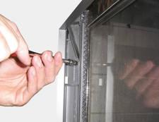
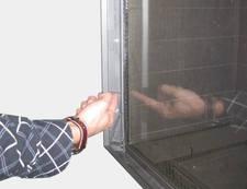
12 INSTLLTION MNUL 5.9 dditional instructions Secure the appliance against the wall using the wall brackets () and rawplugs supplied (see ppendix 3, fig. 1).!aution Glass panes void damaging the glass panes during removal/placing; - void/remove fingerprints on the glass panes, as they will burn into the glass Removing glass pane When removing the front glass pane, you should follow the next steps (see ppendix 3, Fig. 5-16). Remove the vertical decorative strips on the left and right of the glass frame by pushing the lip at the top of each strip up, tilting the top of the strip parallel with the glass frame, and then removing the strip. Remove the horizontal decorative strip by lifting it on one side and taking it out. Unscrew the 4 self-tapping screws in the bottom strip using the socket spanner supplied with the appliance. Loosen the 3 self-tapping screws in the fastening strips on both sides 2 turns.!aution Do not remove the self-tapping screws: leave them in place in the fastening strips. Push the 2 top wedges (left and right) down as far as possible. Push the 2 bottom wedges upwards as far as possible. Press the two fastening strips outwards with your hands as far as possible to avoid damage to the sealing cord. Take hold of the top and bottom handgrips and lift the glass frame. Pull on the bottom handgrip to tilt the glass frame in its mounting towards you and, at the same time, pull the top of the glass frame towards you as far as possible.!aution Make sure you hold the upper handgrip firmly. If you let go of the handgrip then the glass frame could fall inwards and cause severe damage to both the glass and the appliance; Make sure that you lift the glass frame out of its mounting as straight as possible to avoid damage to the paintwork and the sealing cord. Gently allow the glass frame to drop at an angle until it can be removed entirely from the mounting Placing glass pane The glass frame is fitted by using the above procedure, in reverse order.!aution void/remove fingerprints on the glass, since otherwise they will burn into the surface; The self-tapping screws must not be over-tightened, since otherwise they could break or strip the thread: tight=tight; Replace the fastening strip if the sealing cord has come loose. Pay attention to the following when fitting the glass frame: egin by checking that the two fastening strips are pressed outwards as far as possible to avoid damage to the sealing cord. Fit the glass frame. heck that the hook at the top of the glass frame is in position in the seating / U-shaped strip.!tip Pull on the upper handgrip to move the glass frame towards you: if it does not move, then it has been fitted correctly.!aution Fix the glass frame s bottom strip in place with the 4 self-tapping screws. Push both bottom wedges downwards. Push the top wedges upwards until the sealing cord of both fastening strips press against the glass. Tighten each wedge s self-tapping screw.!aution Press on the wedge with your hand to hold it in place while you tighten the screws. Tighten the middle self-tapping screw in each fastening strip. Fit the horizontal decorative strips. Fit the vertical decorative strips.
13 INSTLLTION MNUL 5.11 djustment of the appliance The appliance has to be set in such a way that it works correctly in combination with the discharge system applied. For that purpose, a restrictor slide is placed and/or the air inlet guide is removed. The conditions for application with wall terminal and roof terminal are stated in ppendix 2, Tables 4, 5 and 6. This appliance is suitable for PowerVent. For more information see the PowerVent Installation Manual ir inlet guide The air inlet guides (L) are located at the bottom (side) of the tray around the burner. Remove them as follows (see ppendix 3, Fig. 17). Unscrew the 4 parkers (K) from the tray surrounding the burner (M). Remove the tray surrounding the burner; Unscrew and remove the self-tapping screws; Remove the air inlet guides; Replace the tray round the burner. Screw the 4 parkers (K) in the tray surrounding the burner (M) Restrictor slide The restrictor slide (R) is supplied separately (see ppendix 3, fig. 18). It is mounted as follows: Unscrew the self-tapping screws (S) from the middle plate (T) and remove them. Place the restrictor slide. djust the distance of the restrictor. - in case of a 40 mm setting, the restrictor slide is closed to a maximum level; - in case of a 55 mm setting, the distance must be set by means of a gauge (see ppendix 3, fig. 19). Fix the restrictor slide by using the allen screw (U). Remount the middle plate by using the self-tapping screws.
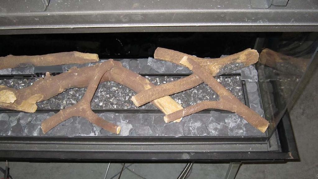
14 INSTLLTION MNUL 5.12 Placing the wood/pebble set The appliance is supplied with a wood set or a pebble set. The vermiculite that is used to fill the burner is black when using the wood set and has a natural colour when using the pebble set.!aution The figures do not always show the correct colours.!aution Strictly observe the following instructions to prevent unsafe situations: only ever use the supplied wood/pebble set; place the wood/pebble set exactly as described; make sure the pilot burner and the surrounding space remain free (see ppendix 3, fig. 20); make sure thermocouple 2 and the surrounding space remain free (see ppendix 3, fig. 21); make sure that the slot between the burner and the vermiculite tray is kept free from objects; make sure there is no vermiculite dust on the burner Wood set The wood set consists of vermiculite (see ppendix 3, fig. 22), chips (see ppendix 3, fig. 23), glow material (see ppendix 3, Fig. 24) and a number of branches (see ppendix 3, fig. 25).!aution The figures do not always show the correct colours. Fill the burner with vermiculite; spread the vermiculite evenly (see ppendix 3, fig. 26). The vermiculite may not come higher than the edge of the burner.!aution - You can influence the flame picture by moving the vermiculite, yet - the burner deck has to remain covered with vermiculite in order to prevent that the life span of the burner is reduced. Fill the vermiculite tray with chips; spread the chips evenly (see ppendix 3, fig. 26). Identify branches up to H (see ppendix 3, fig. 25).!Tip Use the burn stains on the branches for identification. Place branch across the burner, place the ridge of the branch on the positioning bracket (see ppendix 3, fig. 27a): Proceed with branches,, D and E (see ppendix 3, fig. 27b). Then place branches F up to H (see ppendix 3, fig 27c).!aution The branches may not completely cover the burner pattern (see ppendix 3, fig. 28), because: - the main burner will not ignite properly; which could result in unsafe situations; - the appliance will become filthy more quickly, as a result of soot; - the flame picture will be affected Pebble set The pebble set consists of vermiculite (see ppendix 3, fig. 22) and pebbles.!aution The figures do not always show the correct colours. Remove the positioning bracket for the vermiculite tray (see ppendix 3, fig. 29). Fill the burner with vermiculite; spread the vermiculite evenly (see ppendix 3, fig. 26).!aution - You can influence the flame picture by moving the vermiculite, yet - the burner deck has to remain covered with vermiculite in order to prevent that the life span of the burner is reduced. Fill the burner and the vermiculite tray with pebbles. Spread the pebbles evenly over one layer (see ppendix 3, fig. 30).!aution Incorrect placement of the pebbles, e.g. on top of each other, could have the following consequences: - the main burner will not ignite properly, which could result in unsafe situations; - the flame picture will be affected.
15 INSTLLTION MNUL 6. Wireless remote control The appliance is supplied with a wireless remote control. ontrolling the flame height, igniting and switching off take place through a remote control controlling a receiver. hapter 4, Wireless remote control, in the User Manual describes the operation of the appliance and how you should use the remote control.!aution Do not ignite the appliance before the gas and discharge connections have been fully installed, first observe the procedure described in chapter 7.3; elow, we will describe how the receiver is connected. 6.1 onnecting the receiver Your appliance is equipped with an electronic ignition through the remote control. The receiver should be connected to the appliance, before the batteries are installed. onnect the receiver according to ppendix 3, fig. 38. end the antenna (N) out of the clips and place it erect (ppendix 3, fig. 39).!Tip - The plugs have different sizes that correspond with the connectors. - The size of the eye corresponds with the size of the screw; - The colours of eye and screw correspond as well. - Place the batteries as described below in section !aution - Do not place the ignition cable over and/or along metal, stone or concrete parts: this will weaken the spark. Make sure the cable is hanging freely. - Make sure that the wires of thermocouple 2 cannot come into contact with hot parts - Keep the ignition cable at least 10 cm away from the antenna, in order to avoid damaging the receiver. - void formation of dust on or in the receiver: cover it when performing work. - Place the receiver in its intended holder under the appliance or in the control hatch according to ppendix 3, fig If you want to use an adapter, only an adapter supplied by DRU will guarantee a proper operation of the receiver Placing / replacing the receiver's batteries Follow the procedure below when placing the batteries: Pick up the receiver and slide off the cover. Place or remove the 4 penlite ( type) batteries.!aution - Observe the "+" and "-" poles of the batteries and the receiver; - Use alkaline batteries; rechargable batteries are not allowed. - atteries are regarded as "small chemical waste" and may therefore not be disposed with the household rubbish. Slide back the cover. Place back the receiver. 6.2 Setting the communication code Prior to putting the application into operation, a communication code must be set between the remote control and the receiver. If the receiver or the remote control are replaced, a new code will have to be set. Follow the procedure described below: If necessary, place the batteries in the receiver's battery holder; see section If necessary, place the 9V block battery in the remote controle; see User Manual, section 1.1. Hold down the reset button on the receiver, until you hear two consecutive sound signals (see ppendix 3, fig. 40). fter the second, longer signal, let go of the reset button. Press the 'small flame' button on the remote control for 20 seconds, until you hear two short sound signals: this is the confirmation of a good communication. small flame large flame
16 INSTLLTION MNUL 7. Final inspection In order to check whether the appliance is working properly and safely, you must perform the following inspections before the appliance is used. 7.1 Gastightness!aution ll connections must be gastight. heck the connections for gastightness. The gas control can be subjected to a maximum pressure of 50 mbar. 7.2 Gas pressure/line-pressure The burner pressure is set at the factory; see data plate.!aution The line-pressure in house installations must be checked, because it can be wrong. heck the line-pressure; see ppendix 3, fig. 41 for the measuring nipple on the gas control. ontact the gas company if the line-pressure is not correct. 7.3 Ignition pilot and main burner For igniting the pilot and main burner, see the User Manual, chapter 4, section 4.2, Remote control First ignition of the appliance after installation or adjustments!aution fter installation, or after work has been performed, you should ignite the appliance for the first time without the glass window. If necessary, bleed the gas pipe. Follow the procedure described below: If required, remove the glass window; Start the ignition procedure according to chapter 4 in the User Manual; If the pilot flame does not ignite: - repeat the ignition procedure until the pilot burner ignites; - consult the malfunction search diagram (ppendix 1) if this does not happen after a few attempts; fter igniting the pilot flame, the main burner will ignite during the ignition procedure; heck whether the main burner continues to burn; If the main burner does not continue to burn: - repeat the ignition procedure until the main burner continues to burn - consult the malfunction search diagram (ppendix 1) if this does not happen after a few attempts; Switch off the appliance; Then mount the glass window as described in chapter 5.9; Repeat the ignition procedure a few times and perform the checks described in chapter 7.3.2; From now on, the pilot flame should ignite smoothly.!tip When checking whether the main burner continues to burn, it is possible that it still switches off after 22 seconds. This happens because the appliance is equipped with a second thermocouple and the glass window has not been placed. In this case you may presume that the main burner will continue to burn.!aution - During the ignition process, you are not allowed to operate control button on the gas control manually. - lways wait 5 minutes after the pilot flame has gone out, before you re-ignite the appliance. - You are not allowed to turn the pilot flame lower by using the settings on the gas control.
17 INSTLLTION MNUL Main burner!aution - The pilot burner should ignite the main burner within a couple of seconds, and without popping. - The main burner(s) must cross the full burner smoothly and without popping and continue to burn. heck operation of the main burner from a cold condition (pilot flame off): fter opening the gas valve, the main burner should burn within a few seconds.!tip - When the gas valve is opened, the motor will start to run; this is audible. - The flame picture and a good flame transfer can only be properly judged if the glass window is installed. Use the malfunction search diagram (ppendix 1) if the ignition of the main burner does not comply with the abovementioned requirements. 7.4 Flame picture The flame picture can only really be assessed when the appliance has been burning for several hours. Volatile components from paint, materials, etc., which evaporate in the first hours, will affect the flame picture.!aution If the chimney breast has been made of stone-like materials or has a plaster finish, the appliance may only be put into operation 6 weeks after the chimney breast has been placed, in order to prevent shrinkage cracks. heck whether the flame picture is acceptable. onsult the malfunction search diagram (ppendix 1) if the flame picture is not acceptable.
18 INSTLLTION MNUL 8. Maintenance The appliance must be inspected once per year by a skilled installer in the field of gas-fired heating, and repaired if necessary. heck at least whether the appliance is working properly and safely.!aution - lways close the gas tap during maintenance work; - heck the gastightness after repair; - fter replacing thermocouple 1 you should first tighten the gland nut by hand and then give it another quarter turn with a suitable spanner; - You are not allowed to turn the pilot flame lower by using the settings on the gas control. If required, clean the following components: - the pilot burner (malfunction search diagram, ppendix 1); - the space surrounding the pilot burner; - the glass pane(s).!aution - Remove/place the glass pane(s) as described in section 5.10; - Remove the deposit on the inside of the glass pane(s) with a damp cloth or a non-abrasive detergent such as copper polish or a ceramic hot plate cleaner; - void/remove fingerprints on the glass pane(s), since otherwise they will burn into the surface; - Replace a broken and/or cracked glass pane(s) as described in section 5.10.!aution If necessary, replace the wood or pebble set correctly; for this, see section Inspect the flue gas discharge system.!aution You must always perform a final inspection. Perform the inspection as described in chapter Parts Parts requiring replacement can be obtained from your supplier.
19 INSTLLTION MNUL 9. Delivery You must explain to the user how to operate the appliance. You must give him/her instructions on putting it in operation, the safety measures, the operation of the remote control and annual maintenance (see the User Manual).!aution - Tell the user to close the gas tap immediately and contact the installer in case of malfunctions/poor operation. This to prevent unsafe situations; - Indicate the location of the gas tap; - Point out the precautions in the user manual against unintended ignition by other wireless remote controls such as car keys and garage door openers. Instruct the user about the appliance and the remote control. When the appliance is started for the first time, point out that - In order to avoid cracks in a chimney breast made of stone-like materials or finished with plaster, it should dry for at least 6 weeks prior to putting the appliance into operation. - When the appliance is stoked up for the first time, volatile components evaporate from paint, materials, etc. (First read chapter 3 of the User Manual as well!); - When evaporating, the appliance should preferably be set to the highest level; - The room should be well ventilated. Give the manuals to the user (all manuals should be stored near the appliance). 10. Malfunctions In ppendix 1 you will find an overview of malfunctions that might occur, the possible causes and the remedies.
20 INSTLLTION MNUL Start ppendix 1 diagnosis of malfunctions Fires with electronic ignition, fault finding: Ignition and burning 2.01 an pilot be lit? no yes 2.06 Pilot can be lit. Does it stay alight? yes 2.08 Does main burner ignite immediately? yes 2.10 Do(es) main burner(s) ignite smoothly and across its/their full length after after first ignition by pilot burner? yes 2.02 Sparking? yes 2.03 Only one spark? no 2.04 heck: Receiver - Replace missing, weak or rechargeable batteries (not enough power to open thermoelectric valve) Presence of gas on pilot burner heck pilot on presence of gas at normal ignition cycle or in Manual Mode (turn oval knob on gas control to MN and keep safety shut off valve opened with a screwdriver) and ignite pilot with a lighter. - Pilot flame not on: Step 1 - Pilot flame on: Step 2 Step 1: Pilot has no gas - Gas tap open? - Gas at gas control (line pressure at measuring point on gas control). - heck presence of gas at pilot burner, by igniting in Manual mode: Turn oval knob on gas control on MN, open safety shut off valve with a screwdriver and try to ignite pilot with a lighter. Not alight, then check the following: - locking of pilot tube (kink or dirt) - Gas flowing out of gas control? (by loosening pilot tube at gas control) - If not: check adjustment screw pilot flame (under black cover): sealing not to be broken. Sealing broken: screw should be fully open. - If this does not help: replace gas control Step 2: Pilot has gas, but no ignition - Electrode with 90 bended tip: bend tip 1mm higher - Spark too weak (thin and reddish). ct as if 'no spark' in box 2.05 and perform actions described for ignition cable and ignition electrode. - Pilot flame too weak (dirty). Remove injector (remove gland nut and the pilot tube). See that it does not fall away. lean with compressed air. Rectify. Retry. no 2.03a - Loosen and retighten earthing screw on gas control. - If this does not work: replace receiver heck: Ignition cable - Present and connected - eing free from metal parts or concrete - Too long: cut away all excessive length at receiver end, and reconnect - Shorting out to earth; replace ignition cable. - Spark in wrong position - slide rubber sleeve on ignition cable over ceramic of electrode. - Replace electrode if neccessary. Ignition electrode - Straight electrode: - oxidation (roughen electrode with file or sand paper) - position 4 mm from pilot burner - racks in ceramic (not always visible), replace electrode. Thermocouple circuit interrupted - heck connection between: - thermocouple and interruptor - interruptor and gas control Is it tight? (handtight + half a turn) - lack wires (yellow/red end) not (well) connected in thermocouple interruptor, in right position on receiver (in right position) - Thermocouple broken inside thermocouple interruptor: Replace. - Thermocouple interruptor defective. heck by screwing thermocouple directly in gas control and ignition in Manual mode (see 2.04)) Starting procedure fter switching off/going out the remote is locked for 120 sec. (older versions 60 sec). Wait 2 minutes before reigniting. no 2.07 heck thermocouple system Step 1: heck pilot flame and thermocouple - Pilot flame too small - pilot dirty. Rectify (see 2.04) - check for pilot gas tube tightness - pilot tube kinks or dirt inside - line pressure too low - tip not in (correct!) pilot flame. end into flame. Step 2: heck circuit for interruptions or short circuiting - thermocouple tight in interruptor - interruptor tight in gas control - black wires (yellow/red end) - connected to interruptor + receiver - short circuitiong at interruptor Step 3: heck receiver Dismount black-red and -yellow control cables from receiver and link together. Ignite fire in Manual Mode (see 2.04, light pliot with a matchlight): - Pilot stays on: the receiver is defective (replace), and the rest of the thermocouple system is OK. - Pilot goes out: Step 4. Step 4: heck thermocouple and gas control Screw thermocouple directly in gas control and light in Manual Mode (see 2.04, light pliot with a matchlight): - Pilot stays on: Thermocouple interruptor defective. - Pilot goes out: - thermocouple defective - thermo-electric device defective Go to step 5. Step 5: heck thermocouple heck thermocouple by replacing or by measuring output voltage (>5mV, with thermocouple connected). See ppendix 3, fig. 42. Step 6 If thermocouple is not the cause the themo-electric device is defective. Replace gas control. 8-Wire black control cable - 8-wire cable between receiver and gas control not connected. - Poor contact of connector. heck for pins on receiver not being bended. - One of eight wires loose in connector. heck by pulling wire by wire at both ends of cable) no 2.09 Ignition procedure - Oval knob on gas control is on "MN". Set to "ON" and restart. Retarded ignition of main burner Gas to main burner opens ca. 3-5 seconds after servo motor operating the gas valve starts running (sound of motor!). fter this the main burner is to ignite (at least partially) within 10 seconds and not with a firm noise WHOOF. If not: no or delayed cross lighting of main burner. Hazardous situation. Stop ignition procedure straight away and first check for: - Position of logs or pebbles - urner holes (locally) blocked. Remove vermiculite dust. - Vermiculite missing - hips on burner - Vermiculite not distributed evenly across burner(s) PowerVent (if present) onsult PowerVent installation manual how to carry out the checks below. heck: - 230V to fan controller unit and fan - Silicon pressure measurement hoses swapped leaking or barred - Pressure difference set too high - Resistance of flue system too high adjustment of appliance damper and air inlet guides) flue length or number of bends too large dirty (e.g. cobwebs) - Operation of the fan - Operation of solenoid gas valve - Operation of fan controller unit - Operation of pressure measurement gauge no 2.11 No proper cross lighting of main burner(s) Go to box 2.09 and take actions act as described for 'retarded ignition of main burner'. G
21 INSTLLTION MNUL 2.12 Does appliance switch off exactly 22 sec after servomotor starts running? no no yes yes 2.14 Does main burner go out 2.16 Is flame picture OK? 2.18 an fire be switched off? after 'some time'? 2.20 Perfect! You have a well functioning fire yes 2.13 heck cross lighting main burner and 2nd thermocouple system. Wiring - the black and red extension wire of the 2nd thermocouple is connected to: - the 2nd thermocouple (both wires) - the receiver (black wire, can be forgotten during installation) - earth (red wire) Flame transfer main burner - Is flame transfer main burner OK? Flame must heat 2nd couple within approx. 18 sec. (after servomotor starts to run). If not, check: - 2nd couple free from vermiculite, chips or pebbles - Placement of wood blocks or pebbles - urner holes (locally) blocked. Remove (vermiculite) dust - Vermiculite is missing - hips on burner - Lack of combustion air. See Vermiculite not spread evenly over burner(s). Voltage 2nd thermocouple - Measure the voltage of the 2nd thermocouple just before the appliance turns off. - Measure between black extension wire and earth. Voltage <1,8mV Glass window mounted! - Flame transfer main burner too low. See above. orrect this fault, before taking further action!! - Flame suffocates, see orrect, before taking further action!! - urner pressure (too high or too low) - 2nd thermocouple defective (output: 0 mv) - 2nd thermocouple not correct position. end into correct position (see ppendix 3, fig. 43). - 2nd thermocouple in correct position. end deeper into flame (on the condition that flame transfer and flame picture are in order!! See 2.17) 2.15 heck yes Gas supply - Supply pressure does not drop away as main burner (or other appliance) lights, causing pilot flame to shorten - urner pressure (too high or too low) Flames suffocating, lack of air. Dancing flames on burner. - Lack of combustion air. heck: - flue system permissible - proper flue terminal used Make should be 'DRU' - terminal correctly sited on roof or wall relative to obstructions. - integrity of flueing system (no interruptions, not barred, cobwebs) - air inlet guides - flue restrictor/damper - throttle rings PowerVent heck if pressure difference set too high See manual for specific requirements. Pilot burner - Pilot burner dirty. Weak pilot flame being drawn away by flames main burner. lean with compressed air. See heck no Flames: too low - Supply pressure does not drop away as main burner or other appliances in the building light, causing flames to shorten. - urner pressure (too low) - False air: heck soundness glass window gasket/soundness of the connection of the glass panes of two/three sided appliances (no slots allowed) Flames: too high - Line pressure - urner pressure Flames: no even distribution/out on part of burner(s) - Position of logs or pebbles. - urner holes (locally) blocked. Remove vermiculite dust. - Vermiculite not distributed evenly across burner(s) - djustment of throttle ring(s) Remove (vermiculite) dust. - Vermiculite not distributed evenly across burner(s) - djustment of throttle ring(s) Flames: too blue/too yellow or sooting - ir inlet guides - Flue restrictor/damper - Throttle rings Flames: suffocating: lack of air You see dancing flames on burner, seeking for air. See 2.15 Flame picture 'restless' Indication of too much draught. heck: - adjustment of appliance damper and air inlet guides) - vertical flue length allowed (<12m) - window glass not mounted gas tight PowerVent? heck: - Pressure difference set too high - Silicon pressure measurement hoses leaking onsult PowerVent installation manual for more info no 2.19 Replace gas control (thermo-electric valve does not shut down quick enough because of some permanent magnetism) Voltage >1,8mV - Receiver defective. Replace.
22 INSTLLTION MNUL Malfunction search diagram atmospheric gas-fired heating appliance with electronic ignition: Starting up cycle Start 1.01 Does receiver beep? no yes 1.03 One long 5 second beep, (possibly preceded by 7 short beeps) no 1.05 Short beeps, 1sec after another, followed by clicking noise of gas valve opening, possibly followed by ticking sounds of ignition attempts. yes yes no 1.02 Receiver - atteries missing or empty. Replace by 4x. When replacing batteries short beep: no beep: receiver defective. Replace by new one. - Replace rechargeables by alkaline batteries. - ommunication code between remote and receiver has to be (re)set: Press reset button on receiver until brief beep followed by long beep. Release reset button and press 'flame low' button on remote within 20 seconds - Then 2 short beeps and brief noise of servomotor to confirm that communication code was set succesfully. Remote set - attery 9V empty (see indication on display) Several - fter switching off/going out the remote set is locked for 120 sec. (older versions 60 sec). Wait 2 minutes before reigniting heck ll appliances - 8 wire cable between receiver and gas control not connected, poor contact, or one wire loose in connector. (check by pulling wire by wire). - Wiring of thermocouple circuit interrupted, or poor contact. heck thermocouple, thermocouple interrupter and wiring. Sie box Microswitch on gascontrol defective. ppliances with 2nd thermocouple only - 2nd thermocouple not cooled down sufficiently. Wait till cooled down (voltage < 1.2mV, measure between black extension wire and earth). - Wiring of 2nd couple interrupted. heck wiring, see box Else: receiver damaged, replace swift short beeps (within 1 sec time) yes 1.07 Replace batteries 1.08 Remote control system is OK ontinue with "Fires with electronic ignition, fault finding ignition and burning"
23 INSTLLTION MNUL ppendix 2 Part Table 1: Parts included with the delivery Number Wood set / pebble set 1x ontrol hatch ontrol hatch manual Installation manual 1x 1x 1x User manual Decorative strip left Decorative strip right Decorative strip below Gauge for restrictor slide Restrictor slide Key bolts M8x 140x50 Hexagonal nut M8 Washer 8.4 mm Spare self-tapping screws for mounting the glass panes Socket spanner 8 mm Remote control with receiver 9V block battery Penlite battery ( type) ompression fitting 15 mm x G3/8" 1x 1x 1x 1x 1x 1x 2x 2x 2x 4x 1x 1x 1x 4x 1x
24 INSTLLTION MNUL Table 2: Technical data Product name Type of appliance ombustion Supply and discharge system Flame protection version 2nd thermocouple safety tmosphere safety Explosion hatch Ventilation hole chimney breast Type Type of gas urner pressure Nominal heat input (Hs) Nominal heat input (Hi) Nominal output onsumption urner injector onsumption on low output Low setting injector Pilot burner injector Efficiency class mbar kw kw kw L/h mm L/h mm ode: Metro 130 XT + Tunnel uilt-in losed combustion oncentric 200/130 Pilot flame with thermocouple yes no yes 200 cm 2 11/31 G20 G x Ø x Ø Ø 2.00 Ø G x Ø Ø
25 INSTLLTION MNUL Table 3: Line-pressure when using G31 ountry NL / DK / FI / NO / SE / HU / / GR mbar 30 FR / E / IT / PT / ES / G / IE D Permissibility and conditions concentric system with wall terminal Table 4: onditions for setting the appliance G20/G25/G31 Total number of meters vertical pipe length Total number of meters horizontal pipe length (excluding wall terminal) See Figure ir inlet guide Restrictor slide Distance of restriction in mm 0,8 1) ) 4 YES NO OPEN 0,8 1) NO NO OPEN 1) minimum length 2) factory setting!aution In case of a wall terminal, you should always use a diameter of 130/200.
26 INSTLLTION MNUL Permissibility and conditions concentric system with roof terminal Table 5: Determining permissibility concentric system G20/G25/G31 Total number of meters horiz. pipe length Total no. of meters vertical and/or sloping pipe length no bends 2 bends D D D D D D 3 bends D 4 bends 5 bends = Situation is not permissible minimum length G20/G25/G31 Table 6: onditions for the adjustment of the appliance with a roof terminal Situation ir inlet guide Restrictor slide Distance restrictor. in mm NO NO OPEN YES NO OPEN YES YES 55 D YES YES 40!aution If a roof terminal without bends is used, you must first connect a 0.8 metre concentric pipe with a 130/200 mm diameter vertically to the appliance. fter the first metre, reduce the diameter to 100/150mm!aution If a roof terminal with bends is used, you must first connect a 0.8 metre concentric pipe with a 130/200 mm diameter vertically to the appliance. Make the system with a 130/200 mm diameter, and reduce the diameter to 100/150 mm after the last bend.
27 INSTLLTION MNUL ppendix 3 Figures min 857 max min 857 max 907 min. 15 max. 100 V Tot.min 200cm² min min. 350 min. 390 Metro 130XT min. 435 Metro 130XT Tunnel min 220 max /0 Metro 130 XT 394 min 220 max /0 min. 220 Metro 130 XT Tunnel c-1690/0 2 2


28 INSTLLTION MNUL c p-0321 /0


29 INSTLLTION MNUL


30 INSTLLTION MNUL K M R U N L 38c-1691 S T /0 20a 20b 38P-0164/1 38P-0165/1 21a 21b 38P P-0166


31 INSTLLTION MNUL p p P P-0169 D E F G H


32 INSTLLTION MNUL 26 38P a 38P b 38P-0171 E D


33 INSTLLTION MNUL 27c 38P-0172 G F H 28a 38P b 38P-0174


34 INSTLLTION MNUL 29 38c-1657 /0 30a 38P b 38P-0176


35 INSTLLTION MNUL N 38p-0180 V S p p p /0 5mV
Circo G20/G25/G31. Installation manual (GB/IE) English. Store this document in a safe place DRU EN
 English. Store this document in a safe place DRU EN") irco G20/G25/G31 Installation manual (G/IE) Store this document in a safe place 959.044.01. DRU15798-175417-EN--0213-2 INSTLLTION MNUL ontents 1. Introduction 2. E declaration 3. SFETY 3.1 General 3.2
irco G20/G25/G31 Installation manual (G/IE) Store this document in a safe place 959.044.01. DRU15798-175417-EN--0213-2 INSTLLTION MNUL ontents 1. Introduction 2. E declaration 3. SFETY 3.1 General 3.2
Circo RCE G20/G25/G25.3/G31. Installation manual. English. Store this document in a safe place DRU EN-US
 irco RE G20/G25/G25.3/G31 Installation manual Store this document in a safe place 959.044.02.UK DRU-175417-EN-US-1017-4 EN INSTLLTION MNUL ontents 1. Introduction 2. E declaration 3. SFETY 3.1 General
Metro 130XT 41 RCH Metro 130XT Tunnel 41 RCH
 Metro 130XT 41 RH Metro 130XT Tunnel 41 RH G20/G25/G25.3 (Natural gas) G31 (Propane) Installation manual Store this document in a safe place 959.073.02.EN DRU-667777-EN-US-1017-3 EN ontents 1. Introduction
PowerVent. Installation manual (GB) English. Store this document in a safe place UK
 English. Store this document in a safe place UK") PowerVent Installation manual (GB) Store this document in a safe place 959.034.03.UK GB Contents Blz Foreword 3 1. Introduction 3 2. CE declaration 4 3. SAFETY 4 3.1 General 4 3.2 Regulations 4 3.3 Precautions
PowerVent Installation manual (GB) Store this document in a safe place 959.034.03.UK GB Contents Blz Foreword 3 1. Introduction 3 2. CE declaration 4 3. SAFETY 4 3.1 General 4 3.2 Regulations 4 3.3 Precautions
Maestro 80-2 RCH Maestro 80-3 RCH
 Maestro 80-2 RH Maestro 80-3 RH G20/G25/G25.3 (Natural gas) G31 (Propane) Installation manual (/IE) Store this document in a safe place 959.094.04. DRU-677279-EN-US-1016-5 INSTLLTION MNUL ontents 1. Introduction
Paco RCH. G20/G25/G25.3 Natural gas. Installation manual (UK/IE) English. Store this document in a safe place DRU EN-US
 English. Store this document in a safe place DRU EN-US") Paco RH G20/G25/G25.3 Natural gas Installation manual (/IE) Store this document in a safe place 959.098.01. DRU-680093-EN-US-0916-2 ontents 1. Introduction 2. E declaration 3. SFETY 3.1 General 3.2 Regulations
Paco RH G20/G25/G25.3 Natural gas Installation manual (/IE) Store this document in a safe place 959.098.01. DRU-680093-EN-US-0916-2 ontents 1. Introduction 2. E declaration 3. SFETY 3.1 General 3.2 Regulations
Trio RCE. G20/G25/G25.3 (natural gas) Instructions for installation. English. Please retain this document carefully EN
 Instructions for installation. English. Please retain this document carefully EN") Trio RCE G20/G25/G25.3 (natural gas) Instructions for installation Please retain this document carefully 959.064.04.EN EN Contents page Preface 2 1. Introduction 3 2. CE Declaration 3 3. SAFETY 3 3.1 General
Trio RCE G20/G25/G25.3 (natural gas) Instructions for installation Please retain this document carefully 959.064.04.EN EN Contents page Preface 2 1. Introduction 3 2. CE Declaration 3 3. SAFETY 3 3.1 General
PowerVent. Installation manual (GB) English. Store this document in a safe place UK
 English. Store this document in a safe place UK") PowerVent Installation manual (GB) Store this document in a safe place 959.078.00.UK GB Contents page Foreword 3 1. Introduction 3 2. CE declaration 4 3. SAFETY 4 3.1 General 4 3.2 Regulations 4 3.3 Precautions
PowerVent Installation manual (GB) Store this document in a safe place 959.078.00.UK GB Contents page Foreword 3 1. Introduction 3 2. CE declaration 4 3. SAFETY 4 3.1 General 4 3.2 Regulations 4 3.3 Precautions
User manual (GB / IE) for appliances provided with an electronic ignition on the remote control. English. Read this document and store it carefully
 for appliances provided with an electronic ignition on the remote control. English. Read this document and store it carefully") User manual (GB / IE) for appliances provided with an electronic ignition on the remote control Read this document and store it carefully 958.007.07.uk 1 UK Contents page Preface 2 1. Introduction 3 2.
User manual (GB / IE) for appliances provided with an electronic ignition on the remote control Read this document and store it carefully 958.007.07.uk 1 UK Contents page Preface 2 1. Introduction 3 2.
PowerVent Installation manual. English. Store this document in a safe place EN
 PowerVent - 02 Installation manual Store this document in a safe place 959.114.01.EN en Contents Page Foreword 3 1. Introduction 3 2. CE declaration 4 3. SAFETY 4 3.1 General 4 3.2 Regulations 4 3.3 Precautions
Metro 70 - Metro 70 Tunnel
 Metro 70 - Metro 70 Tunnel G31 propane Instructions for installation (GB / IE) Please retain this document carefully UK Contents page Foreword 2 1. Introduction 3 2. EC Declaration of Conformity 3 3. SAFETY
Clear Installation guide
 Clear 40010631-0938 ENG Installation guide ENG 1.1 1.2 1.3 A 1.4 1.5 1 < < < < A B 2.1 2.2 2.3 C 2.4 2.5 2 < < < < 3.1 3.2 3-3 3 < < < < Inhoudsopgave 1 Introduction... 6 2 Safety instructions... 6 3 Installation
Duet XL /0929. Installation guide
 Duet XL 40010749/0929 ENG Installation guide ENG 1.1 1.2 1.3 1.4 1.5 A 1.6 1.7 1 < < < < B A 2.1 2.2 2.3 2.4 2 < < < < 2.5 2.6 2.7 2.8 3 < < < < 3.1 F F 3.2 3.3 4 < < < < Table of contents 1 Introduction...
Fyn Installation guide
 Fyn 600 4001131-1123 ENG Installation guide ENG 1.1 1.2 A B 1.3 1.4 1 < < < < 2.1 2.2 2.3 2.4 3.1 3.2 2 < < < < 4.1 4.2 4.3 4.4 3 < < < < 1 Introduction The appliance can only be installed by a competent
Solution Installation guide
 Solution 40011444-1327 ENG Installation guide ENG 1-1 1-2 1-3 1.4 1 < < < < 2.1 2-3 2-4 2 < < < < 3-1 3.2 3-3 3.5 3.6 3 < < < < 4-1 A 4-2 4-3 4 < < < < Dimensions Terminal position Distance (For good working
Fyn Installation guide
 Fyn 450 400100929-1114 ENG Installation guide ENG 1.1 1.2 A B 1.3 1.4 1 < < < < 2.1 2.2 2.3 3.1 3.2 2 < < < < 4.1 4.2 4.3 4.4 3 < < < < Table of contents 1 Introduction... 6 2 Safety instructions... 6
Respect OC Installation manual
 Respect OC 40011335-1235 ENG Installation manual ENG 1.1 1.2 A 1.3 1.4 A A 2.1 2.2 2.3 1 < < < < 2.4 2.5 B C A B A 2.6 2 < < < < 3.1 3.2 3.3 3.4 3.5 3.6 3 < < < < A B 3.7 4 < < < < L A A 4.1 A A 4.2 A
Servicing manual. Wall-mounted condensing gas boiler 600 Series - 11S / 19S / 24S / 24C /2002 GB(EN) For trade use
 For trade use") GB122 7210 1300-12/2002 GB(EN) For trade use Servicing manual Wall-mounted condensing gas boiler 600 Series - 11S / 19S / 24S / 24C Please read thoroughly before attempting to diagnose fault List of contents
GB122 7210 1300-12/2002 GB(EN) For trade use Servicing manual Wall-mounted condensing gas boiler 600 Series - 11S / 19S / 24S / 24C Please read thoroughly before attempting to diagnose fault List of contents
Servicing manual. 600 Series - 11S / 19S / 24S / 24C. Wall-mounted condensing gas boiler. For trade use
 GB122 Servicing manual Wall-mounted condensing gas boiler 600 Series - 11S / 19S / 24S / 24C For trade use Please read thoroughly before attemting to diagnose fault 7217 4900 (03/2010) GB/IE List of contents
CRYSTAL FIRES. Inset Conventional Flue Fire. (BOSTON/MIAMI) Cf1 and MANHATTAN USER INSTALLATION AND SERVICING INSTRUCTIONS
 Cf1 and MANHATTAN USER INSTALLATION AND SERVICING INSTRUCTIONS") CRYSTAL FIRES (BOSTON/MIAMI) Cf1 and MANHATTAN Inset Conventional Flue Fire USER INSTALLATION AND SERVICING INSTRUCTIONS FOR USE WITH NATURAL GAS G20 @ 20 mbar For use in GB and IE CE THESE INSTRUCTIONS
CRYSTAL FIRES (BOSTON/MIAMI) Cf1 and MANHATTAN Inset Conventional Flue Fire USER INSTALLATION AND SERVICING INSTRUCTIONS FOR USE WITH NATURAL GAS G20 @ 20 mbar For use in GB and IE CE THESE INSTRUCTIONS
INSTALLATION AND MANINTENANCE INSTRUCTIONS
 INSTALLATION AND MANINTENANCE INSTRUCTIONS Appr. Nr. A 9503 T - 0085 AQ 0765 PEGASUS F2 T HIGH EFFICIENCY GAS-FIRED CAST-IRON BOILERS Models 51-68 - 85-102 2 Contents 1. General technical data 2. Dimensional
Installation Manual EF5000 AUS & NZ
 Installation Manual EF5000 AUS & NZ This manual is ONLY for fires with a serial No. from 80600 to 80999. Important: The appliance shall be installed in accordance with; Local gas fitting regulations Municipal
Vaska Logburner. voorbeeld Installation guide
 Vaska ogburner voorbeeld 40010627-2103 ENG Installation guide ENG 1.1 1.2 1.3 1.4 1.5 1 < < < < 1 Introduction The appliance can only be installed by a competent person in accordance with the Gas Safety.
Kalahari DECORATIVE FUEL EFFECT GAS FIRE
 Kalahari DECORATIVE FUEL EFFECT GAS FIRE User Instructions These instructions should be read by the user before operating the appliance and retained for future reference Model No. KRDC00MN & KRDC00SN are
VASKA C11. gas-fireplace user manual. Saturnus 8 NL-8448 CC Heerenveen Postbus 219 NL-8440 AE Heerenveen T. +31(0) F.
 F.") VASKA C11 gas-fireplace user manual Saturnus 8 NL-8448 CC Heerenveen Postbus 219 NL-8440 AE Heerenveen T. +31(0)513 656500 F. +31(0)513 656501 40 010 458 01.51 DESCRIPTION OF THE FIREPLACE CONTENTS 1 2
VASKA C11 gas-fireplace user manual Saturnus 8 NL-8448 CC Heerenveen Postbus 219 NL-8440 AE Heerenveen T. +31(0)513 656500 F. +31(0)513 656501 40 010 458 01.51 DESCRIPTION OF THE FIREPLACE CONTENTS 1 2
Relaxed Premium M Relaxed Premium M ENG
 Relaxed Premium M 40010959 1440 Relaxed Premium M ENG 3 alternative finishes. 1.1a 1.1b 1.1c 1 < < < < 1.2 1.3 7 1.4 2 < < < < 1.5 1.6 B 1.9 3 < < < < 2.1 2.2 2.3 3.1 3.2 3.3 3.4 4 < < < < 3.5 4.1 4.2
VASKA C11. gas -fireplace installation guide
 VASKA C11 gas -fireplace installation guide Saturnus 8 NL-8448 CC Heerenveen Postbus 219 NL-8440 AE Heerenveen T. +31(0)513 656500 F. +31(0)513 656501 40 010 459 01 51 DESCRIPTION OF THE FIREPLACE CONTENTS
HG 675 CX 60 HG 675 CN 60 HG 675 CW 60
 HG 675 X 60 HG 675 CX 60 HG 675 CN 60 HG 675 CW 60 1 2 1. : 93/68: 90/396: 2006/95/CE: 2004/108/CE: - 1935/2004:. 2002/95/CE: RoHS 2.,.,,,,...,. (,..)..,,.,. ( ),,, ;,,.,.....,.,,,,,,...,. (..),,.,..,.,,,,
VASKA B11. gas -fireplace installation guide
 VASKA B11 gas -fireplace installation guide Saturnus 8 NL-8448 CC Heerenveen Postbus 219 NL-8440 AE Heerenveen T. +31(0)513 656500 F. +31(0)513 656501 40 010 446 01 51 DESCRIPTION OF THE FIREPLACE CONTENTS
Duet Premium M Duet Premium M ENG
 Duet Premium M 40011422-1441 Duet Premium M ENG 1.1 1.2 1.3 1.4 1.5 1.6 1.7 1.8 1 < < < < 2.1 a 2.1 b 2.1 c A C 2.2 2 < < < < F F 2.3 X H X C 2.4 2.5 S T 3.1 3.2 R Q 3.3 3 < < < < 4.1 4.2 4.3 4.4 4 <
USHO COOKER INSTALLATION INSTRUCTIONS SAFETY INSTRUCTIONS USER INSTRUCTIONS MODEL: USHO. INSTRUCTION REF: IN152 ISSUE No. 4 DATE
 Page 1 of 11 INSTALLATION INSTRUCTIONS SAFETY INSTRUCTIONS USER INSTRUCTIONS USHO COOKER MODEL: USHO Page 2 of 11 WARNING To avoid scratching the highly polished exterior surface of this equipment whilst
Outdoor Tabletop Heater TTH20 Series
 Outdoor Tabletop Heater TTH20 Series FEATURES: The ideal solution for extending the outdoor entertaining season Creates a stylish and attractive ambience Casts an approximate 1 to 1.5 metre circle of radiant
FLAME HEATER PYRAMID CLFH-10SS OPERATION INSTRUCTIONS
 FLAME HEATER PYRAMID CLFH-10SS OPERATION INSTRUCTIONS www.colorato.net For outdoors use only Uses propane, butane or LPG only Reflector: 47x47 mm Total Height: 2250 mm Regulator s external pressure: 28-30
INSTALLATION & USERS INSTRUCTIONS. FOR USE WITH NATURAL GAS 20 mbar For use in GB and IE
 1 valentine s buildings Bechers drive Aintree racecourse Business Park L9 5ay CF1 L GAS APPLIANCE INSET CONVENTIONAL FLUED GAS FIRE INSTALLATION & USERS INSTRUCTIONS FOR USE WITH NATURAL GAS G20 @ 20 mbar
FIREPLACE INSTALLATION
 CHECK GAS TYPE Use proper gas type for the fireplace unit you are installing. If you have conflicting gas types, do not install fireplace. See retailer where you purchased the fireplace for proper fireplace
IMPORTANT SAFETY INSTRUCTIONS DANGER: WARNING:
 IMPORTANT SAFETY INSTRUCTIONS YOUR SAFETY AND THAT OF OTHERS IS PARAMOUNT This manual and the appliance itself provide important safety warnings, to be read and observed at all times. This is the attention
JUNEAU JUN. 08/51193/0 Issue 0
 JUNEAU JUN 08/51193/0 Issue 0 The product complies with the European Safety Standards EN60335-2-30 and the European Standard Electromagnetic Compatibility (EMC) EN55014, EN60555-2 and EN60555-3 These cover
Installation Manual EF5000 NZ
 Installation Manual EF5000 NZ Important: The appliance shall be installed in accordance with; Local gas fitting regulations Municipal building codes AS/NZS 5601.1.1:2010 Gas Installation Any other relevant
HORIZONTAL COOKING SERIES: 700 / 900 S.A.V MAINTENANCE & AFTER SALES WORK PPS-3WE711911CH
 SERIES: 700 / 900 S.A.V MAINTENANCE & AFTER SALES WORK PPS-3WE711911CH GENERAL Tools Every time you se this symbol it is vital that you have the tool indicated to ensure correct and compliant work is undertaken
Gas Instantaneous Water Heater
 6 720 607 823 GB (06.06) SM Installation and Operating Instructions Gas Instantaneous Water Heater WR10..B... WR11..B... With electronic ignition and triple safety system consisting of ionisation detector,
GLOBAL 40 CF FITTING INTO A CONVENTIONAL CLASS 1 CHIMNEY
 INSTALLATION INSTRUCTIONS GB/IE GLOBAL 40 CF FITTING INTO A CONVENTIONAL CLASS 1 CHIMNEY DRU VERWARMING B.V. HOLLAND 957.669.00 CONTENTS Site: 3 Important 3 Foreword 4 Instructions for installation 4 Ventilation
Installation and Operation Manual For Hunter Ceiling Fans
 Installation and Operation Manual For Hunter Ceiling Fans 1 2 CONGRATULATIONS! Your new Hunter ceiling fan is an addition to your home or office that will provide comfort and performance for many years.
THE INSTRUCTIONS IN THIS MANUAL APPLY TO KENT GAS FIRES. CONTENTS:-
 THE INSTRUCTIONS IN THIS MANUAL APPLY TO KENT GAS FIRES. THE MODELS COVERED ARE:- For use with Natural Gas:- KENT ESTATE NG, KENT ULTIMA NG For use with Liquid Propane Gas (LPG):- KENT ESTATE LP, KENT
Duet Premium L Duet Premium L ENG
 Duet Premium L 40011297-1441 Duet Premium L ENG 1.1 1.2 1.3 1.4 1.5 1.6 1.7 1.8 1 < < < < 2.1 a 2.1 b 2.1 c A C 2.2 2 < < < < F F 2.3 X H X C 2.4 2.5 S T 3.1 3.2 R Q 3.3 3 < < < < 4.1 4.2 4.3 4.4 4 <
INSTALLATION AND USER S MANUAL COOKER HOOD RS-600/A-S
 INSTALLATION AND USER S MANUAL COOKER HOOD RS-600/A-S RS-600 (CHS60SS)-GB-05.indd 1 6/8/2010 9:30:59 AM TABLE OF CONTENTS 1. Introduction 2 2. Safety precaution 2 3. Intended use 3 4. Parts supplied 3
WAILEA OWNER S MANUAL
 WAILEA OWNER S MANUAL The blades in each pack are matched for equal weight to assure smooth fan operation. If more than one fan is being installed, be careful not to mix blades from different cartons.
21 20 LITER GAS FRYER FFA3200 INSTALLATION AND SERVICING.
 21 20 LITER GAS FRYER FFA3200 INSTALLATION AND SERVICING www.anvilworld.com 20 ALL ANVIL EQUIPMENT COMES WITH A ONE YEAR WARRANTY ON COMPONENTS AND DEFECTIVE WORKMANSHIP. www.anvilworld.com 19 20 LITER
Operating Instructions Wine storage refrigerator 12/
 Operating Instructions Wine storage refrigerator 12/98 7080641 1 The wine storage refrigerator you have purchased differs from normal refrigerators in that it is suitable for long-term storage of wine.
16 Ultiflame Inset Electric Fire
 16 Ultiflame Inset Electric Fire B-1001645 Packing Checklist Electric Fire Remote Control Handset 2 x AAA Batteries Log Set Ember Ice Set Instruction Manual Fascia IMPORTANT PLEASE READ THESE INSTRUCTIONS
Imperial Electric Fires
 Imperial Electric Fires GB IE MODELS: Flamescape II Curvascape II manual & remote. Installation and User Instructions PLEASE READ THESE INSTRUCTIONS CAREFULLY AND RETAIN FOR FUTURE REFERENCE This electric
USER MANUAL. 60cm, 3 burners, Hob AKC 630
 USER MANUAL 60cm, 3 burners, Hob AKC 630 For your safety These instructions have been drawn up for your safety and that of others. You are therefore requested to read them carefully before installing
LIMITED LIFETIME WARRANTY
 LIMITED LIFETIME WARRANTY Model No.: F0003 aireryder ORIGINAL CEILING FAN LIMITED LIFETIME WARRANTY The limited lifetime warranty covers this ceiling fan, for residential use by the original purchaser,
Instructions for use. Gas hobs for installation in worktops GKS GWS GKS GKS
 Instructions for use Gas hobs for installation in worktops GKS 3920.0 GWS 3911.0 GKS 6940.0 GKS 9951.0 For use in: Hong Kong Issue: 2014-01-14 Version: 1.3_EN Identity no.: 073587_HK Welcome 2 Welcome
chaffoteaux ltd. CORVECELT TS CONFORMS WITH EUROPEAN (BS5386Ptl) EN26 installation servicing requirements
 EN26 installation servicing requirements") chaffoteaux ltd. CORVECELT TS CONFORMS WITH EUROPEAN (BS5386Ptl) STANDARD EN26 installation servicing requirements contents Page 3 : TECHNICAL DATA Pages 4 and 5 : INSTALLATION Pages 6 and 7 : SERVICING
chaffoteaux ltd. CORVECELT TS CONFORMS WITH EUROPEAN (BS5386Ptl) STANDARD EN26 installation servicing requirements contents Page 3 : TECHNICAL DATA Pages 4 and 5 : INSTALLATION Pages 6 and 7 : SERVICING
LIMITED LIFETIME WARRANTY
 LIMITED LIFETIME WARRANTY Model No.: F0023 / F0024 aireryder ORIGINAL CEILING FAN LIMITED LIFETIME WARRANTY The limited lifetime warranty covers this ceiling fan, for residential use by the original purchaser,
ELECTRIC FLAT PANEL FIREPLACE HEATER
 ELECTRIC FLAT PANEL FIREPLACE HEATER Model Numbers: 80-2000A-42 OWNER S MANUAL AC 120V 60Hz 1500W WARNING Read and understand this entire owner s manual, including all safety information, before plugging
USER MANUAL. 80 cm 2 burners, glass hob AKC 820C/BLM
 USER MANUAL 80 cm 2 burners, glass hob AKC 820C/BLM For your safety These instructions have been drawn up for your safety and that of others. You are therefore requested to read them carefully before installing
50 FLAT PANEL BUILD IN ELECTRIC FIREPLACE
 50 FLAT PANEL BUILD IN ELETRI FIREPLAE Model Numbers: 1703 OWNER S MANUAL WARNING Read and understand this entire owner s manual, including all safety information, before plugging in or using this product.
Built-in Gas Hob CZ55554 CZ55571
 Built-in Gas Hob CZ55554 CZ55571 INSTALLATION AND OPERATING INSTRUCTIONS The product may differ from the one illustrated but the installation and operation procedure remains the same The product may differ
Installation Instructions & Operating Manual IMPORTANT
 Installation Instructions & Operating Manual IMPORTANT These instructions should be read carefully and retained for future reference TABLE OF CONTENTS SECTION 1: WARNINGS & ELECTRIC SPECIFICATIONS 1.1
Fully-automatic Gas tankless Water Heater USER'S MANUAL FOR MODEL EZ-101 ISO9001 certified
 Fully-automatic Gas tankless Water Heater USER'S MANUAL FOR MODEL EZ-101 ISO9001 certified Thank you for purchasing our fully-automatic gas-fired tankless water heater. Please completely read this Manual
Instructions for use
 Instructions for use These instructions are also available on the website: www.kitchenaid.eu Important instructions for safety 4 Installation 6 Safeguarding the environment 6 Troubleshooting guide 7 After-sales
LIMITED LIFETIME WARRANTY
 LIMITED LIFETIME WARRANTY Model No.: F0030 aireryder ORIGINAL CEILING FAN LIMITED LIFETIME WARRANTY The limited lifetime warranty covers this ceiling fan, for residential use by the original purchaser,
SAFIRE 2000A FUEL OIL HEATER INSTALLATION, OPERATION AND MAINTENANCE
 SAFIRE 2000A FUEL OIL HEATER INSTALLATION, OPERATION AND MAINTENANCE You have selected the new generation SAFIRE oil heater as your heating solution. Although our goal is to take into account all problems
Heat Exchanger Block Replacement Instructions
 Series 1-4 Gas-fired water boiler Heat Exchanger Block Replacement Instructions Ultra-80 S1-4 Heat Exchanger Block Replacement Kit, Part No. 383-500-773 Ultra-105 S1-4 Heat Exchanger Block Replacement
ASTRO PORTABLE LPG CABINET HEATER Model No. KCH
 ASTRO PORTABLE LPG CABINET HEATER Model No. KCH205-002 PLEASE READ CAREFULLY BEFORE USE These instructions should be read in conjunction with the Assembly and Safety Instructions on pages 3-7. After initial
MHG201 Gas Hob Manual for Installation, Use and Maintenance
 MHG201 Gas Hob Manual for Installation, Use and Maintenance 1 Customer Care Department The Group Ltd. Harby Road Langar Nottinghamshire NG13 9HY T : 01949 862 012 F : 01949 862 003 E : customer.care@cda.eu
LIMITED LIFETIME WARRANTY
 LIMITED LIFETIME WARRANTY To obtain Service, please contact or call Turn of the Century Service Department: 1-800-887-6326, 9 a.m.- 5 p.m. central time. Model No.: # 355-6782 The limited lifetime warranty
HVG620 & HVG720 Gas Hob Manual for Installation, Use and Maintenance
 HVG620 & HVG720 Gas Hob Manual for Installation, Use and Maintenance Customer Care Department The Group Ltd. Harby Road Langar Nottinghamshire NG13 9HY T : 01949 862 012 F : 01949 862 003 E : customer
51AKB / 51 AKC OWNER S MANUAL
 51AKB / 51 AKC OWNER S MANUAL This manual applies to the following models 51AKB 009 51AKB 012 51AKC 009 51AKC 012 Read this instruction manual thoroughly before using the air conditioner. Control panel
Glass and Dishwashers AMX / AUX Series
 Glass and Dishwashers AMX / AUX Series INSTALLATION OPERATION VERSION 24.02.04 Important Notes Use in Accordance with Regulations This machine is exclusively to be used to wash ware such as plates, cups,
Installation Instructions
 Installation Instructions KFN 9855 ide en - CA Installation, repair and maintenance work should be performed by a Miele authorized service technician in accordance with national and local safety regulations
72 ONYX XL FLAT PANEL ELECTRIC FIREPLACE
 72 ONYX XL FLAT PANEL ELECTRIC FIREPLACE Model Numbers: 80005 OWNER S MANUAL WARNING Read and understand this entire owner s manual, including all safety information, before plugging in or using this product.
Stainless Steel and Glass Angled Extractor
 Stainless Steel and Glass Angled Extractor HJA2600 User & Installation Guide CONTENTS Environmental Note 3 Product information 4 4 Parts List 4 Method of Extraction 5 Installation 6 Hanging Your Extractor
CONTENTS QUICK REFERENCE GUIDE INSTRUCTIONS FOR USE PROGRAMME CHART BOOKLET
 ONTENTS QUIK REFERENE GUIDE PROGRAMME HART PREPARING THE LAUNDRY SELETING A PROGRAMME AND OPTIONS STARTING AND OMPLETING A PROGRAMME HANGING A PROGRAMME INTERRUPTING A PROGRAMME DAILY MAINTENANE AND LEANING
Patio Heater Model No. GM and GM
 Patio Heater Model No. GM124-003 and GM124-004 FEATURES: The ideal solution for extending the season for outdoor entertaining Maximum output 39.6 MJ/hr Direct ignition Adjustable heat output Safety tip-over
CLASSIC II QUATTRO DECORATIVE FUEL EFFECT APPLIANCES FOR USE WITH NATURAL GAS IIN INSTALLATION, SERVICING & USER INSTRUCTIONS
 CLASSIC II QUATTRO DECORATIVE FUEL EFFECT APPLIANCES FOR USE WITH NATURAL GAS IIN INSTALLATION, SERVICING & USER INSTRUCTIONS THESE INSTRUCTIONS MUST BE LEFT WITH THE USER MANUFACTURED BY: MULTIGLOW FIRES
Installation instructions Refrigerators and freezers for integrated use, door-on-door
 Installation instructions Refrigerators and freezers for integrated use, door-on-door 010612 7084276-04 IK/ IKB/ IKP/ IG/ IGN... 1/ 3/ 6 General safety information Contents 1 General safety information...
Installation Instructions Horizon Natural Draft Electronic Ignition Gas Fireplaces
 Installation Instructions Horizon Natural Draft Electronic Ignition Gas Fireplaces Installation Instructions Horizon Natural Draft Electronic Ignition 3 Sided Gas Fireplaces Natural Draft Electronic Ignition
Propane Heater REMKO PGM 30 REMKO PGM 60
 Propane Heater REMKO PGM 30 REMKO PGM 60 Operation Technology Spare Parts Edition GB L07 REMKO strong as a bear. Operating instructions Make sure to read these instructions carefully before starting/using
JLBIHD624 60cm Cooker Hood
 JLBIHD624 60cm Cooker Hood User guide 2 Cooker hood user guide Contents Contents 3 Introduction 4 Safety is important 4 In the box 4 Safety information 5 Important safety information 5 Warnings 5 Cautions
DISHWASHER. Models DW2432 and DW2432SS. Installation Manual. Write Serial Number (on inner door of unit) here:
 here:") DISHWASHER Models DW2432 and DW2432SS Installation Manual Write Serial Number (on inner door of unit) here: Felix Storch, Inc. Summit Appliance Division 770 Garrison Avenue Bronx, New York 10474 www.summitappliance.com
DISHWASHER Models DW2432 and DW2432SS Installation Manual Write Serial Number (on inner door of unit) here: Felix Storch, Inc. Summit Appliance Division 770 Garrison Avenue Bronx, New York 10474 www.summitappliance.com
(manual control) (ezi-slide control) INSET COAL EFFECT GAS CONVECTOR FIRE V1/100/B INSTALLATION & USER INSTRUCTIONS
 (ezi-slide control) INSET COAL EFFECT GAS CONVECTOR FIRE V1/100/B INSTALLATION & USER INSTRUCTIONS") Model Number: V1/100/A V1/100/B (manual control) (ezi-slide control) INSET COAL EFFECT GAS CONVECTOR FIRE INSTALLATION & USER INSTRUCTIONS GB IE SUITABLE FOR USE ON NATURAL GAS (G20) AT 20mbar SUPPLY PRESSURE
Model Number: V1/100/A V1/100/B (manual control) (ezi-slide control) INSET COAL EFFECT GAS CONVECTOR FIRE INSTALLATION & USER INSTRUCTIONS GB IE SUITABLE FOR USE ON NATURAL GAS (G20) AT 20mbar SUPPLY PRESSURE
Installation & Service Instructions
 Part No. 966/9350/1 02 Potterton Housewarmer Illusion ASD - G.C. NO. 37 590 16 966 Inset DGF with ILLUSION FACIA Potterton Housewarmer Stratton ASD - G.C. NO. 37 590 17 966 Inset DGF with STRATTON FACIA
Stainless Steel Chimney Extractor
 Stainless Steel Chimney Extractor HJA2450-2 User & Installation Guide LAMONA Appliances Dear Customer, Congratulations on your choice of a LAMONA domestic appliance which has been designed to give you
LUNA 850 V GOLD GAS INSTRUCTION FOR INSTALLATION AND USE. Passion for fire
 LUNA 850 V GOLD GAS INSTRUCTION FOR INSTALLATION AND USE Passion for fire SUMMARY 1. GENERAL REMARKS...3 2. CONNECTION...3 3. SPECIFICATION SHEET...4 4. ASSEMBLY OF THE CHIMNEY...5-7 5. ELECTRICAL CONNECTION...8
HAWK GAS STOVE. Installation and Servicing Instructions
 HAWK GAS STOVE Installation and Servicing Instructions Please leave this instruction booklet with the user after the installation is complete. Leave the system ready for operation and instruct the user
Installation and maintenance instructions
 6304 4994 03/2006 GB For installer Installation and maintenance instructions Flue gas heat exchanger WT30/40 Please read thoroughly prior to installation and maintenance. Contents Contents Contents 2 1
G-7s. Instruction Manual. G-Series Cooler COUNTERTOP COOLER. Part No.11IPA
 G-Series Cooler COUNTERTOP COOLER Part No.11IPA-061000 Instruction Manual FOR YOUR FUTURE REFERENCE This easy-to-use manual will guide you in getting the best use of your cooler. Remember to record the
OWNERS INSTRUCTION MANUAL
 OWNERS INSTRUCTION MANUAL 132CM/52 Classic INSTALLATION OPERATION MAINTENANCE CAUTION READ INSTRUCTIONS CAREFULLY FOR SAFE INSTALLATION AND FAN OPERATION. IF UNSURE CONSULT A QUALIFIED ELECTRICIAN SUITABLE
GAS HEATERS MODEL NOS: DEVIL 700, 900/910SS,1600/ 1610SS & 2100 PART NOS: , , , , , &
 GAS HEATERS MODEL NOS: DEVIL 700, 900/910SS,1600/ 1610SS & 2100 PART NOS: 6920182, 6920186, 6920188, 6920190, 6920192, &6920194 USER INSTRUCTIONS ORIGINAL INSTRUCTIONS GC0318 iss2 INTRODUCTION Thank you
GrateGlow THE ALL NEW CAPITAL COLLECTION. G20 at 20mbar convertible to G31 at 37mbar. For use in GB and le. Users Instructions
 GrateGlow A CARVER GROUP COMPANY --..--... THE GAS CONSUMERS' COUNCIL (GCC) IS AN INDEPENDENT ORGANISATION WHICH PROTECTS THE INTEREST OF GAS USERS. IF YOU NEED ADVICE, YOU WILL FIND THE TELEPHONE NUMBER
Stainless Steel Chimney Extractor
 Stainless Steel Chimney Extractor User & Installation Guide LAM2404 LAMONA Appliances Dear Customer, Congratulations on your choice of a LAMONA domestic appliance which has been designed to give you excellent
Kalahari RC & Camber RC
 Kalahari RC & Camber RC DECORATIVE FUEL EFFECT GAS FIRE User Instructions These instructions should be read by the user before operating the appliance and retained for future reference Model No s KRDC**RN
COOKER HOOD USER MANUAL
 COOKER HOOD USER MANUAL TROUBLE SHOOTINGS CAUTION: Disconnect the power supply before servicing. STATUS The power supply is damaged CAUSE AND METHOD OF REPAIRING If the power supply is damaged,please call
SAFIRE 1600D, 1800D and 2100D Diesel / fuel oil heaters USAGE, INSTALLATION AND MAINTENANCE
 SAFIRE 1600D, 1800D and 2100D Diesel / fuel oil heaters 1 Heater kit contains : Heater, mounting bracket Fuel hose (3 meters), pump, a fuel tank connection to standard tanks (15, 22, 30 litres) Power supply
OWNER S MANUAL MOBILE GAS BARBECUE WITH SIDE BURNER
 OWNER S MNUL MOBILE GS BRBECUE WITH SIDE BURNER Picture of ppliance Read this instruction carefully and ensure that your grill is properly installed, assembled, maintained and serviced in accordance to
Service Manual Model 3163
 Service Manual Model 3163 Contents Important Safety Information.......... 1 Specifications.................. 2 General Information.............. 2 Direct Vent Requirements........... 2 Propane System................
Gas Fire Patio Heater Q9
 Gas Fire Patio Heater Q9 Instruction Manual Please read the manual BEFORE you unpack or install the fire TABLE OF CONTENTS Warning 3 Getting Started 4 What s Included 5 Assembly Procedures 6 Product Drawing
SPECIFICATIONS PART NAME
 SPECIFICATIONS MODEL High HEAT RATING Low FUEL TANK CAPACITY BURNING TIME DIMENSIONS(W x D x H) WEIGHT VOLTAGE / FREQUENCY ELECTRICAL CONSUMPTION LC-S27 9,900 BTU / 2.9 kw 2,900 BTU / 0.8 kw 4.0 lit. 14.2~