PowerVent Installation manual. English. Store this document in a safe place EN
|
|
|
- Clinton Newton
- 5 years ago
- Views:
Transcription

1 PowerVent - 02 Installation manual Store this document in a safe place EN en
2 Contents Page Foreword 3 1. Introduction 3 2. CE declaration 4 3. SAFETY General Regulations Precautions / safety instructions during installation 4 4. Instructions 5 5. Principle of the ignition cycle 5 6. Removing the packaging 6 7. Installation Regulations Electric connection Placing the PowerVent system Flue gas / combustion air system Pressure gauge pipes Control system Adjusting the appliance Points of departure Explanation of the table Type of appliance Differential pressure Minimum length Maximum length Length of condense trap Maintenance Parts Malfunctions 22 Appendix 1 Parts included with the delivery 23 Appendix 2 Technical specifications 24 en 2
3 Foreword As a manufacturer of gas-fired heating appliances, DRU is developing and producing products in accordance with the highest possible quality, performance and safety requirements. This guarantees that the user will be able to enjoy using his product for many years to come. This PowerVent system has a CE marking, which means that it complies with the essential requirements of the European gas appliance directive. Installation and maintenance of the appliance should be performed by a professional certified expert with a proven knowledge and demonstrable competence in this field. A professional expert takes all technical aspects such as heat output, gas connection and electricity into account, as well as the flue gas discharge requirements. The installation manual will provide you with the information you need to install the PowerVent system in such a way that the appliance to be placed will operate properly and safely in combination with this system. This installation manual will replace the section flue gas discharge / combustion air supply system in the installation manual for the appliance. If the installation instruction is not clear, national/local regulations must be observed. This manual will discuss the installation of the PowerVent system and the accompanying regulations. In addition, you will find information on maintenance, as well as possible malfunctions and their possible causes. Appendix 2 contains the technical specifications that are needed for connecting the PowerVent system. Carefully read this installation manual and use it in combination with the installation manual of the appliance to be placed.!tip! The following symbols are used in the manual to indicate important information: Work to be performed Suggestions and recommendations You will need these instructions to prevent problems that might occur during installation and/or use. You need these instructions to prevent fire, personal injury or other serious damages. After delivery, you should give this installation manual to the user. 1. Introduction The PowerVent system is a combined, concentric flue gas discharge / combustion air supply system with a forced discharge of the flue gases. It is an additional, independent system that can be connected to various DRU atmospheric gas-fired heating appliances. The forced discharge of flue gases is realized by means of a fan connected to the outlet of the flue gas discharge. By using a ventilator, the flue gases can be discharged over a longer distance than was previously possible for DRU appliances. In order to prevent the fan from malfunctioning, a minimum length is required for the PowerVent system. The maximum length depends on the number of bends in the system. In Appendix 2 Technical specifications you will find the requirements for minimum and maximum length. The passage to the outside can be made by means of a wall terminal or a roof terminal. The roof terminal can end in a sloping or a flat roof. In case of a roof terminal, the fan unit can be placed on the inside or outside of the roof. The advantage of a fan unit on the inside of the roof, is that it will be easier to reach. If it is placed on the outside of the roof, you will need an addition to the fan unit, the rooftop unit. DRU has a number of rooftop units in its range. You will select whether the fan unit is placed on the inside or outside of the roof, when you purchase the PowerVent system. The diameter of the concentric PowerVent system is 60/100 mm. This system is connected by means of an adapter to the flue spigot of the appliance. DRU has a number of concentric adapters in its range. When installing the concentric system in rooms prone to moisture, you must use a coated air supply pipe. It can be supplied through your dealer 3 en
4 2. CE declaration Internal precautions at the company will guarantee that appliances produced by DRU comply with the essential requirements and directives of the regulation concerning gas combustion appliances and the standards applied for that purpose. This declaration will lose its validity if adjustments are made to the appliance, without prior written permission by DRU. A copy of the CE test certificate can be downloaded via Product: flue gas discharge / combustion air supply system Type: PowerVent Conformity assessment agency: Kiwa 0063 EC regulations: 2016/426/EU EC-directives: 2014/35/EU 2014/30/EU Applied harmonized standards: NEN-EN-613 NEN-EN-613/A1 NEN-EN-613/A2 NEN-EN NEN-EN R.P. Zantinge Managing director Postbus 1021, 6920 BA Duiven Ratio 8, 6921 RW Duiven 3. SAFETY 3.1 General - Carefully read this chapter on safety, before you start performing installation or maintenance work; - Please observe the general regulations and the precautions/safety instructions in this manual. 3.2 Regulations Please install the PowerVent system, including the electrical installation, in accordance with the applicable national, local and constructional (installation) regulations. In the Netherlands, the Buildings Decree (Bouwbesluit) applies. 3.3 Precautions / safety instructions during installation Carefully observe the following precautions/safety regulations: You should only install and maintain the PowerVent system if you are a competent installer in the field of gas-fired heating and electricity. The control hatch is obligatory when installing PowerVent and is available via the manufacturer. Take into account a larger chimney breast due to the control hatch with PowerVent control. Maintain a distance of 50mm between the bracket with the electronic components and cables to the appliance. Do not make any changes to the system. Take the minimum length of the PowerVent system into account. Place the adapter directly on the appliance s flue spigot. Place the measuring unit (venturi) preferably vertical, within 1 metre of the flue spigot. Connect the pressure gauge pipes leak-tight, before the chimney breast is placed. Make sure the pressure gauge pipes are free from parts that will become hot. Avoid dirt, including metal particles in pipes and connections. Avoid kinks in the pipes. Place electric wiring in such a way that it is free from the appliance. For connecting the ventilator, you must use an earthed 230V supply cable that complies with the applicable standard. When performing work at the installation, you must disconnect it from the power supply by removing the 230V plug from the socket. Both the Honeywell control unit with Powervent and the ventilator Replace damaged mains sockets in order to avoid dangerous situations. Use a coated air supply pipe when installing in rooms prone to moisture. en 4

.")
5 4. Instructions This PowerVent system is only suitable for the DRU control system with Honeywell (RCH) Take into account a larger chimney breast due to the control hatch with PowerVent control. Maintain a distance of 50mm between the bracket with the electronic components and cables to the appliance. Place a 230V connection with earth near the appliance, as close as possible to the control hatch. Test the complete system for a correct operation, before closing the chimney breast. 5. Principle of the ignition cycle Below you will find a brief description of how an appliance, that is connected to the PowerVent system, is ignited; see fig. 1). The following corresponding letters can be found in the figure: A.Remote control E. Fan B. Receiver F. Measuring unit (Venturi) C. Gas control G. Reduction to ø100/60 D. PowerVent control unit H. Pressure sensor The appliance is switched on by means of a remote control (A). Via the remote control, the receiver (B) will get the signal to start the ignition process. At the same time, the control unit (D) of the PowerVent system will get a start signal from the receiver. The fan switches on and after the set pressure difference has been achieved, the ignition will start directly on the burner. It is established whether there is sufficient flow in the discharge system. For this, the pressure sensor (H) is used to measure the differential pressure over the measuring unit (venturi, (F)). If the differential pressure is greater than the set value on the control unit (D), the valve in the Honeywell gas control (C) is opened and the gas to the main burner of the appliance is released. If the differential pressure is below the set value, the main burner of the appliance will not ignite. In the malfunction table in Chapter 10 you will find possible causes and solutions. PWM 10V 230 V E F G 38C-2560 /0 H Honeywell A PWM 10V D 230 V B C 1 5 en
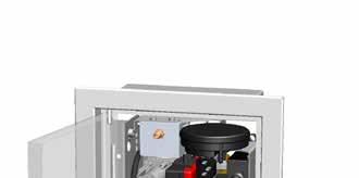
6 6. Removing the packaging Note the following items when removing the packaging of the PowerVent system: Check the system for damages during transport. If necessary, contact DRU Service. Check whether all parts have been supplied. In Appendix 1 / Table 2 you can see which parts you should have after removing the packaging. Contact DRU Service if you do not have all the parts after you finished removing the packaging. Dispose of packaging in accordance with local regulations. 7. Installation! Read this manual carefully to ensure a proper and safe operation of the appliance connected to the PowerVent system. Install the PowerVent system in the order described in this chapter. 7.1 Regulations - Observe the applicable national, local and constructional (installation) regulations for the PowerVent system as well as the electric installation. - Observe the regulations/instructions stated in this manual. 7.2 Electric connection The ventilator of this Powervent system has a PWM controlled ventilator. This PWM signal (maximum 10V) is transported across a 2-core cable with cores of maximum 0.75mm 2. The cores are intended for the PWM signal and GND (see fig. 3d and fig.4b and 7b(s)). The 2-core cable is hereafter referred to as: control cable. Furthermore, two 230V earth connections must be made: - The connection for the appliance should be as close to the control hatch as possible - and the 230V connection for the ventilator must be installed close to both the appliance and the ventilator. - Make sure that it is easy to disconnect the appliance and ventilator from the power supply after installation; - by disconnecting the 230V plug; - or by means of a 2-core switch installed by a recognised installer in accordance with current regulations. - Replace damaged mains sockets in order to avoid dangerous situations. 7.3 Placing the PowerVent system The PowerVent system allows many different configurations; see fig. 2a to 2c. The system will be installed after the appliance has been built on its final location. The bracket with the PowerVent control components (control unit and pressure sensor) must be connected to the controller of the appliance (such as the gas control) ex factory, so that the whole unit can be placed in the control hatch as described in this manual. The pressure gauge pipes are out of reach after placing the chimney breast. A leak will affect the gauge signal to the pressure sensor and therefore the combustion process. That is why these pipes must be connected free from leaks before fully finishing the chimney breast.!tip - Make sure the PowerVent control system is properly connected to the control system of the appliance and fits in the control hatch; - Connect the pressure gauge pipes to the measuring unit, before the chimney breast is completed; - Check whether the pressure gauge pipes are connected leak-tight before finishing the chimney breast. - The aluminium pipes must be protected against possible corrosive effects, e.g. as a result of moisture, fallen down mortar, dirt fallen down from the chimney, etc. The pilot flame pipe must be kept permanently free from the ground and the walls of the area in which the appliance is built. When installing in an existing fireplace, or if it is not possible to keep the pipes free, the pipe should be protected against corrosion by means of a jacket. - Take into account a larger chimney breast due to the of the control hatch with PowerVent control. Maintain a distance of 50mm between the bracket with the electronic components and cables to the appliance. When connecting the assembled PowerVent control components and Honeywell control components, we recommend making a gas connection with an approved, flexible SS gas pipe. This will significantly simplify adjustments and troubleshooting, as the whole assembly can be removed from the hatch. en 6
7 For the benefit of the installation, the PowerVent system has been subdivided in a number of parts: - flue gas / combustion air system; see section pressure gauge pipes; see section control system; see section Flue gas / combustion air system The passage to the outside can be made with a wall terminal, as displayed schematically in fig. 2d (see section ), as well as a roof terminal (see section ). The roof terminal can be placed in a sloping or a flat roof. When a roof terminal is chosen, the fan unit can optionally be placed on the inside of the roof (see schematic display in fig. 2e and fig. 2f) or on the outside (see schematic display in fig. 2g and fig. 2h. For placement of the fan unit on the outside of the roof, you will need an additional rooftop unit. The solution on the inside of the roof can be made with a wall terminal (see fig 2i). Chapter 8 states a few conditions. The appliance must be adjusted in such a way that it will function properly in combination with the PowerVent system; see chapter 8 of this manual, Adjusting the appliance. The diameter of the concentric PowerVent system is 60 / 100 mm. This system is connected by means of an adapter to the flue spigot of the appliance.! - For the PowerVent system you should only use the concentric flue gas discharge material supplied by DRU. This system has been tested together with the appliance. DRU cannot guarantee a proper and safe operation of other systems and does not accept any liability for this; - Take the minimum length of the PowerVent system into account; see section and appendix 2 with the technical specifications; - Take the maximum length of the PowerVent system into account; see sections and and appendix 2 with technical specifications; - Place the adapter directly on the appliance s flue spigot; see fig. 1, G; - Place the measuring unit (venturi) preferably vertical, within 1 metre of the flue spigot; see fig. 1, F; - Place the fan unit correctly; - Use 2 individual cables for the control signal and for the earthed 230V power supply to the ventilator. - Place the ventilator s control cable in a cable protection sleeve. - Place the ventilator s earthed 230V power supply cable in a cable protection sleeve. - For connecting the ventilator, use an earthed 230V power supply cable that complies with the applicable standard. - Make sure that it is easy to disconnect the ventilator unit free from the power supply after installation. - Make sure the pressure gauge pipes are free from parts that will become hot; - Maintain a distance of at least 50 mm between the outside of the PowerVent system and the walls and/or the ceiling. If the system is built in (for instance) a cove, it should be made with non combustible and heat-resistant material all around it; - Use a coated air supply pipe when installing in rooms prone to moisture; - Use non combustible and heat-resistant insulation material when passing through combustible material; - The first 5 metres of the air supply / flue gas discharge pipe must be safely separated from combustible material by means of a non combustible plate, if the distance between the pipe and the combustible material is less than 100 mm. If the pipe is surrounded by combustible material, it should be sleeved with non combustible material and the sleeve must be ventilated. - Heat bridges, e.g. by means of mounting brackets, should be avoided. - For larger distances than 5 metres, a 50 mm safety distance from combustible materials should be observed. - The manufacturer is unable to accept liability for discharge pipes poured in concrete or buried discharge pipes, as the pipes will be out of reach. If you want this after all, we recommend the following: If the discharge pipe is poured in concrete, it should be surrounded by a heat resistant 200 C pipe sleeve. If the discharge pipe runs through the ground, it will have to be surrounded by a durable 200 C and water-tight pipe sleeve. It should be placed with a slope (1cm/m) towards the inside and a condensation discharge should be placed, even if this is not prescribed according to table 3. There should be no locations where possible condensation water cannot be discharged. If necessary, take measures to prevent rainwater or sprinkler water from entering the system. - Make sure the ventilator unit can be reached for maintenance; - Make sure the control cable and earthed 230V power supply cable is sufficiently long; - Some heat-resistant insulation materials contain volatile components that will spread an unpleasant smell for a prolonged time; these are not suitable. 7 en
8 POWERVENT - INSTALLATION MANUAL 2a 38c c c b 2c 2d 38C e 38C-1542 en 8
9 38c C f 2g 38C C h 2i 9 en
10 Application with wall terminal The temperature of (the outside of) the concentric system can reach 200 ºC at the wall. Placing the PowerVent system is done as follows: Check whether the concentric system to be applied complies with the minimum and maximum allowed length; see section and and appendix 2 with the technical specifications. Build the system up from the flue spigot of the appliance. Place the adapter directly on the appliance s flue spigot. Place the measuring unit (venturi) preferably on the adapter. Connect the concentric pipe pieces and the bends. Make sure that the clip binding with silicone sealing ring is mounted correctly, in order to prevent leakage at the connections.! On each connection, apply a clip binding with silicone sealing ring. Fasten the clip binding to the pipe using a self-tapping screw. Apply sufficient clamps, so that the weight of the pipes does not rest on the appliance. Remove the cover of the fan unit. Make a hole in the wall for the concentric system (see fig. 3a for the dimensions and fig. 3b). Make a hole in the façade for the protection sleeve of the 230V power supply cable and for the protection sleeve of the control cable to the ventilator (see fig. 3a for the dimensions and fig. 3b). Fix the fan unit to the wall (see fig. 3a for the dimensions and fig. 3c). Cut the pipe piece that is used for connecting to the fan unit to size. Make sure that the right insertion length is maintained. Connect the pipe piece to the fan unit. - Make sure the inlet of the fan unit properly connects to the concentric system; - Make sure that the control cable and the 230V power supply cable are connected exactly as shown in fig. 3d in order to avoid contact between the cables and the hot ventilator. Connect the control cable and earthed 230V power supply cable to the connector (see fig. 3d). Lay the control cable - provided with cable protection sleeve - towards the appliance. Lay the earthed 230V power supply cable - provided with cable protection sleeve - towards the earthed 230V connection. Seal the back plate of the ventilator unit at the top and bottom with a suitable sealant (see fig. 3e). Place the cover back on the fan unit (see fig. 3f). Place the flue gas discharge pipe (see fig. 3h). Fix the cover with the self-tapping screws supplied (see fig. 3g) Application with roof terminal The roof terminal can end in a sloping or a flat roof. In case of a passage through the roof, the fan unit can be placed on the inside or outside of the roof. If it is placed on the outside of the roof, you will need an addition to the fan unit, the rooftop unit (see the schematic display in fig. 2g and 2h). en 10

")


11 (2x) 160 3a 38C-2563 /0 38C b 38P c 38P d 38P e 38P f 38P g 38P h 38P en

 preferably on the adapter. Connect the concentric pipe pieces and the bends.")

12 Placing the fan unit on the inside of the roof Placing the PowerVent system is done as follows: Check whether the concentric system to be applied complies with the minimum and maximum allowed length (see section and and appendix 2 with the technical specifications). Build the system up from the flue spigot of the appliance. Place the adapter directly on the appliance s flue spigot. Place the measuring unit (venturi) preferably on the adapter. Connect the concentric pipe pieces and the bends. Make sure that the clip binding with silicone sealing ring is mounted correctly, in order to prevent leakage at the connections. On each connection, apply a clip binding with silicone sealing ring. Use a self-tapping screw to fix the clip binding to the pipe on locations that cannot be reached after installation. Apply wall brackets at each pipe connection, so that the weight of the pipes does not rest on the appliance. Place the strip that is used for connecting the fan unit s clamps (see fig. 4a, 1). Attach the fan unit s clamps to the strip (see fig. 4a, 2). Remove the cover of the fan unit. Place the fan unit on the clamps.!tip! The fan unit can be turned and can therefore be placed on the clamps in four ways. Choose the way that is most practical for you. Secure the fan unit with the self-tapping screws supplied. Connect the control cable and earthed 230V power supply cable to the connector (see fig. 4b). Make sure the control cable and earthed 230V power supply cable are sufficiently long, because of maintenance work. - Make sure that the control cable and the 230V power supply cable are connected exactly as shown in fig. 4b in order to avoid contact between the cables and the hot ventilator; - Make sure the cover is placed correctly on the fan unit, so that the outlet of the fan connects to the outlet of the cover. Lay the control cable - provided with cable protection sleeve - towards the appliance. Lay the earthed 230V power supply cable - provided with cable protection sleeve - towards the earthed 230V connection. Place the cover back on the fan unit (see fig. 4c. Secure the cover with the self-tapping screws supplied. Connect the concentric system to the fan unit.!! Use a telescopic pipe piece for connecting the concentric system. As a result, it will be easier to perform maintenance work. Place the roof terminal on the fan unit. - Make sure that the universal tile fits well with the surrounding tiles; - Make sure that the adhesive plate fits well onto the flat roof a 38P b 38P-0781 en 12


13 c 38P a 38P Placing the fan unit on the outside of the roof Placing the PowerVent system is done as follows: Check whether the concentric system to be applied complies with the minimum and maximum allowed length (see section and and appendix 2 with the technical specifications). Build the system up from the flue spigot of the appliance. Place the adapter directly on the appliance s flue spigot. Place the measuring unit (venturi) preferably on the adapter. Connect the concentric pipe pieces and the bends.!! Make sure that the clip binding with silicone sealing ring is mounted correctly, in order to prevent leakage at the connections. On each connection, apply a clip binding with silicone sealing ring. Use a self-tapping screw to fix the clip binding to the pipe on locations that cannot be reached after installation. Apply sufficient clamps, so that the weight of the pipes does not rest on the appliance. Make a hole in the roof for the concentric system. Make a hole in the roof for the protection sleeve of the 230V power supply cable and for the protection sleeve of the control cable to the ventilator. Place the rooftop unit on the roof (see fig. 5a for application with a flat roof). Remove the cover of the fan unit. Place the fan unit on the rooftop unit. ut the pipe piece that is used for connection to the rooftop unit to size. Make sure that the right insertion length is maintained. Connect the pipe piece to the rooftop unit. - Make sure the inlet of the fan unit properly connects to the concentric system; - Make sure that the control cable and the 230V power supply cable are connected exactly as shown in fig. 4b in order to avoid contact between the cables and the hot ventilator; - Make sure the cover is placed correctly on the fan unit, so that the outlet of the fan connects to the outlet of the cover; - When placing the upper part and the cover, make sure the outlets connect onto each other. Attach the rooftop unit and the fan unit to each other, using the self-tapping screws supplied. Connect the control cable and earthed 230V power supply cable to the connector (see fig. 4b). Lay the control cable - provided with cable protection sleeve - towards the appliance. Lay the earthed 230V power supply cable - provided with cable protection sleeve - towards the earthed 230V connection. Place the cover back on the fan unit (see fig. 4c). Place the upper part and the cover of the version that is placed on the outside of the roof (see fig. 5b). Attach the upper part and the cover to the fan unit, using the self-tapping screws supplied. - Make sure that the universal tile of the rooftop unit fits well with the surrounding tiles; - Make sure that the adhesive plate fits well onto the flat roof. 13 en
 in order to measure the differential pressure over the measuring unit. The first part of the pressure gauge pipes is made of aluminium.")

14 P1 P2 5b 38C p P Pressure gauge pipes The pressure gauge pipes are attached between the measuring unit (fig. 1, F) and the pressure sensor (fig. 1, H) in order to measure the differential pressure over the measuring unit. The first part of the pressure gauge pipes is made of aluminium. The aluminium pipes must be mounted in such a way that they do not touch the parts that become hot. Moreover, the gauge pipes must be attached without strain. The aluminium gauge pipes run until below the appliance. After that they will change into silicone hoses. Finally, the silicone hoses are connected to the pressure sensor. The pipes must be cut to size on site. Follow the next steps: Connect the brass elbow joints (2 items) to the measuring unit; see fig Tighten the joints until they are leak-tight; after installation you will no longer be able to reach them; - Make sure the pressure gauge pipes are free from parts that will become hot; - Remove any burrs after shortening the pipes; - Avoid dirt, including metal particles in pipes and connections; - Avoid kinks in the pipes; - Make sure that the transition from aluminium pipe to silicone hose can always be reached. Roll out the aluminium pipes towards the appliance. Connect the aluminium pipes to the brass joints; see fig. 6. Attach the aluminium pipes in such a way that there is no strain. Determine the length of the aluminium pipes. Saw the pipes to size. Connect the silicone hoses to the aluminium pipes.! The silicone hoses can only be connected to the pressure sensor, after the bracket with the control system has been placed. The pressure sensor is on the bracket with the control system Control system The control system consists of the elements that are needed to allow the appliance to work safely in combination with the PowerVent system. These components (control unit and pressure sensor) are mounted on a bracket that can be connected to the bracket with the Honeywell control components, in order to then mount them in the obligatory control hatch. This control hatch is available via the manufacturer. Ex factory, the bracket with the PowerVent control components is already mounted on the bracket with the Honeywell control components and the appliance has already been fully adjusted for Powervent. If this is the case, step 1 can be skipped. If the appliance and the bracket with the PowerVent control components is supplied separately, all points from point 1 must be observed. en 14


15 P A G(in) I1 M J 38C-2561 /0 7a 15 en
16 - The PowerVent system is only permitted in combination with an accompanying, lockable control hatch that comes with the appliance, in order to be able to meet the safety requirements. This control hatch is available via the manufacturer; - Take the safety requirements into account when placing the control hatch, as described in the installation manual for the appliance concerned; - Connect the correct silicone hose to the correct connection point on the pressure sensor; see fig 6, P1 and P2. If applicable. - proceed as follows when placing the control system. Or else, go to step 2: 1. The bracket with the PowerVent control components will fit on the bracket with the Honeywell control components in only one way (see fig. 7a): - Place the bracket with the PowerVent control components on the bracket with the Honeywell control components, in such a way that the display (I1) at the front can be operated and read. Make sure that connector A of the Power- Vent control components is connected to connector A of the Honeywell control components. - Replace bridge plug (M) with the supplied bridge plug without blue cable in the Honeywell unit. For this, unscrew the cover (J) from the Honeywell control unit, replace the bridge plug and place the cover back on the control unit; - Attach the 2 brackets with the 3 self-tapping screws (P). 2. Pull the pressure gauge pipes and the ventilator s control cable to the outside through the control hatch. Make sure the control cable (S) is fastened with a cable tie and allow it to protrude approx. 250mm (see fig. 7b). If necessary, remove the Honeywell receiver from the control hatch at the front. 3. Remove the Powervent control unit from the bracket at the front and connect the ventilator s control cable (S) to the green PCB terminal block (V1) of the control unit (see fig. 7b). 4. Connect the pressure gauge pipes to the pressure sensor, so that (see fig. 6 and fig. 7b): - the pipe comes as close as possible to the appliance s flue spigot at P1; - the other pipe ends at P2. 5. Make sure the appliance is prepared for first ignition as described in the installation manual of the appliance concerned. 6. Finally, make sure the earthed 230V power supply cable of the ventilator is connected to an earthed 230V connection.; The PowerVent system is now ready for testing.!tip Testing should be performed prior to finishing the chimney breast and before mounting the assembly of PowerVent control components and Honeywell control components in the control hatch. Check all connections for gastightness, before igniting the appliance. Test the PowerVent system for proper operation. Check the setting of the differential pressure on the adjusting unit and set correctly, if necessary. If the appliance does not ignite, the differential pressure must be set within 50 seconds. - The differential pressure that has to be set depends on the appliance; The differential pressure is adjusted as follows (for the values, see appendix 2 with the technical specifications): Briefly press button (B) 1x, and the percentage of the ventilator s capacity is visible (F.00 to F.99 is possible) (see fig. 8). Turn the button clockwise 1x and the current pressure difference is visible in Pascal (005 to 350 is possible) Now press down the button for 10 seconds and the pressure difference set-point appears. The currently set pressure difference now flashes. Check that this is the correct value. If not, increase or lower the button per 5, until the correct pressure difference value is achieved. Now press down the button for 2 seconds to confirm. Then, the current pressure difference is shown. After 60 seconds the display will switch off automatically. en 16


17 S + ~250mm P1 P2 S V1 I1 38C-2562 /1 7b B 8 38c-2559 /0 17 en
18 POWERVENT - INSTALLATION MANUAL!!Tip If the system operates to your satisfaction, proceed as described above: Isolate the system from its supply voltage. Place the complete assembly of appliance controller and PowerVent controller in the control hatch (see fig. 7a). Make sure that hereafter the control hatch is locked in accordance with the regulations. Reconnect the voltage supply to the system. It is sensible to measure whether the required pressure difference is achieved and only then close the chimney breast or cove around the discharge system. en 18
19 8. Adjusting the appliance This chapter provides the technical specifications that are required for the PowerVent system to operate properly in combination with the appliance. Appendix 2, table 3 contains the conditions; the conditions depend on the type of appliance. The appliance must be installed without air inlet guide(s) and without the restrictor slide that is supplied with the appliance. The appliance is supplied with the Powervent system installed and the above-mentioned components have therefore already been removed. If the appliance is not supplied with the Powervent installed, these components will have to be removed after all.! Consult the most recent installation manual of the appliance for possible additional settings. The most recent installation manual can be found on Points of departure Application of the PowerVent system is allowed up to a certain maximum length. Each bend is calculated as 2 metres. No distinction is made between 45 and 90 bends. Example: According to table 3 in appendix 2, the maximum allowed length in case of the Lugo 70 is 43 metres. If three bends are used, a maximum of 37 metres of concentric pipe may be connected. 8.2 Explanation of the table Below, the layout of table 3 in appendix 2 is explained Type of appliance This column lists the appliances that are suitable for connection to PowerVent Differential pressure This column shows the differential pressure, in Pascal, which has to be set on the adjusting unit Minimum length This column indicates the minimum length of the PowerVent system, in metres, that is necessary in order to prevent the fan from becoming defective. The minimum length is the real length in metres of concentric pipe. Here, the bends may NOT be included in the calculation (2 metres are 1 bend). In case of a solution below the roof with wall or roof terminal, a concentric pipe of maximum 1 metre may be placed between the fan unit and the wall or roof terminal. Do NOT include this metre in the calculation when determining the minimum length of the concentric pipe Maximum length This column states the maximum length of the PowerVent system. The maximum length is the real length is metres of pipe. In case of a solution below the roof with wall or roof terminal, a concentric pipe of maximum 1 metre may be placed between the fan unit and the wall or roof terminal. DO include this metre in the calculation when determining the maximum length of the concentric pipe. The bend at the wall terminal (counts for 2 metres) is also included in the calculation. The wall terminal, on the other hand, is NOT included Length of condense trap If flue gases have to be transported over a long distance, they may cool down to below dew point, and condensation may occur. The condensation generated must be discharged via a condense trap. From a certain length, a condense trap will have to be placed. It concerns the real length in metres of pipe. Use a condensation receptacle with stench-trap. If an odour trap is used, it should be filled with water at all times. It may not become dry. A consequence of a dry odour trap could be that the appliance no longer switches on or that the discharge gases flow into the water discharge system. This means that a condense discharge should always be connected to a siphon filled with water. There are other possibilities as well. For instance, it is possible to use a liquid free odour trap. An example of this is the Hepworth HepvO, Hygienic self sealing waste valve. This module is available at DRU. 19 en
20 ! - The condensation receptacle may not become dry. - A temperature of the exhaust gases that is too high could damage the condensation receptacle. That is why the condensation receptacle should be placed after a minimum length of the concentric system. Consult table 3. Add 4 metres to the stated minimum length of the concentric system. The result is also the most ideal distance for placing the condensate receptacle. Place the condensate receptacle in a horizontal section of the concentric pipe. Ensure a minimum slope of 1 cm per metre for the concentric pipe to the condensation trap.! - In some situations more than one condensate receptacles (see fig.9, C) should be placed. This is the case if the concentric pipe shows a downwards and then upwards slope AFTER the indicated minimum length (see fig. 9, B) and this pattern is repeated. - The slope must be made in such a way that the condensed water flows against the direction of the exhaust gas. In this way, the condensed water enters at the correct side of the condensate drain section and is discharged in the correct manner (see fig. 9). The condensate receptacle is available at your dealer and can be supplied by DRU. C B C 38c-1557 /01 9 en 20
21 9. Maintenance Once a year the system should be checked, cleaned and, if necessary, repaired by a competent installer in the field of atmospheric gas-fired heating and electricity. During the performance of work, disconnect both the appliance and ventilator from the power supply as follows: - remove the 230V plug from the connection of the appliance and/or ventilator; - or switch off the 2-core switch of the appliance and/or ventilator placed by a recognised installer in accordance with current regulations. 9.1 Parts Parts that must be replaced, can be obtained from your supplier. 21 en
22 10. Malfunctions In the following table you will find an overview of malfunctions that might occur, the possible causes and the remedies Table 1: diagnosis of malfunctions Problem Possible cause Remedy A. fan is activated, but appliance does not ignite. code between receiver and 1. The (new) communication remote control must still be confirmed. 2. The odour traps of the condense trap are dry. 3. Control cable not connected correctly. 4. Ventilator s power cable not connected correctly. B. Does spark, but does not ignite. (Honeywell) 1. Fan not connected or blocked. 2. Silicone hoses are not connected leak-tight. 3. Maximum length / max. number of bends of the Power- Vent exceeded. 4. Flue gas discharge is not connected leak-tight. 5. Pressure gauge hoses have been connected the wrong way around. 1. Confirm the code, as described in the Installation Manual of the appliance, chapter Malfunctions, in the table under solution A1. 2. Make sure there is sufficient water in the odour traps or use liquid free odour traps. (see chapter 8.2.5) 3. Check that the control cable is properly connected to the green terminal block. 4. Check that the 230V power cable is correctly connected to the ventilator. 1. Check whether the fan rotates after the appliance has been ignited. - If necessary, connect the ventilator; - If necessary, repair blockage 2. Check the connections. If necessary, connect the silicone hoses leaktight. 3. Check length and number of bends. If necessary, correct to max. length / max. number of bends. 4. Check connections and silicone rings for leaktightness. If necessary, connect them leak-tight. 5. Properly connect the hoses. en 22
23 Appendix 1 Parts included with the delivery In the following table you can find the parts that are supplied with the appliance. Table 2: Parts included with the delivery Part Number Installation manual 1x Bracket with control system (Honeywell (RCH)): Mounted - Control unit - Pressure sensor Aluminium pressure gauge pipe 2x Silicone pressure gauge pipe (hose) 2x Joints nx Screws nx Ventilator unit + Measuring unit (Venturi) Separately available 23 en
24 Appendix 2 Technical specifications Type of appliance Differential pressure Table 3A: Technical specifications Minimum length Maximum length Length condense trap Control unit with lower limit (Pa) (metre) (metre) (metre) (Pa) Cosmo RCH (tunnel) n.v.t. 100 Excellence 50XT > Lugo > Lugo > Maestro 75 RCH > Maestro 75 RCH tunnel > Maestro 75 XTU RCH 175 4,5 53 > Maestro 80-2 RCH > Maestro 80-3 RCH > Maestro 100 RCH 175 6,5 34 > Maestro RCH > Maestro RCH > Metro 80 XT RCH (tunnel) > Metro 100 XT 41 RCH (tunnel) > Metro 100 XT2 41 RCH > Metro 100 XT3 41 RCH > Metro 100 XTL 41 RCH > Metro 100 XTU 41 RCH > Metro 130 XT 2 RCH > Metro 130 XT 3 RCH > Metro 130 XTL RCH > Metro 130 XT 41 RCH (tunnel) > Metro 150 XT 41 RCH (tunnel) > Metro > Paco RCH > Bends (45º or 90º) are calculated as 2 metres, when determining the maximum length. - The resistance of one condensation trap is included in the specified maximum length. If an extra condensate trap is installed, 4 metres must be deducted from the maximum length, in respect of each condensate trap. en 24
25 Type of appliance Table 3B: Technical specifications (discontinued appliances) Differential pressure Minimum length Maximum length Length condense trap (Pa) (metre) (metre) (metre) Centro > 12 Excellence > 17 Excellence > 17 Metro 100 XT RCH (tunnel) > 18 Metro 100 XT2 RCH > 17 Metro 100 XT3 RCH > 17 Metro 100 XTL RCH > 18 Metro 130 XT RCH (tunnel) > 20 Metro 150 XT RCH (tunnel) > 14 Prestige RCH (tunnel) > 18 Bends (45º or 90º) are calculated as 2 metres, when determining the maximum length. 25 en
26 POWERVENT - INSTALLATION MANUAL Table 4: Technical specifications PowerVent PowerVent Fan Wall/Roof terminal V (AC) Hz W db max PowerVent control en 26
27 POWERVENT - INSTALLATIEHANDLEIDING Notes 27
28 POWERVENT - INSTALLATION MANUAL DRU Verwarming B.V. The Netherlands Postbus 1021, NL-6920 BA Duiven Ratio 8, NL-6921 RW Duiven en
PowerVent. Installation manual (GB) English. Store this document in a safe place UK
 English. Store this document in a safe place UK") PowerVent Installation manual (GB) Store this document in a safe place 959.034.03.UK GB Contents Blz Foreword 3 1. Introduction 3 2. CE declaration 4 3. SAFETY 4 3.1 General 4 3.2 Regulations 4 3.3 Precautions
PowerVent Installation manual (GB) Store this document in a safe place 959.034.03.UK GB Contents Blz Foreword 3 1. Introduction 3 2. CE declaration 4 3. SAFETY 4 3.1 General 4 3.2 Regulations 4 3.3 Precautions
PowerVent. Installation manual (GB) English. Store this document in a safe place UK
 English. Store this document in a safe place UK") PowerVent Installation manual (GB) Store this document in a safe place 959.078.00.UK GB Contents page Foreword 3 1. Introduction 3 2. CE declaration 4 3. SAFETY 4 3.1 General 4 3.2 Regulations 4 3.3 Precautions
PowerVent Installation manual (GB) Store this document in a safe place 959.078.00.UK GB Contents page Foreword 3 1. Introduction 3 2. CE declaration 4 3. SAFETY 4 3.1 General 4 3.2 Regulations 4 3.3 Precautions
User manual (GB / IE) for appliances provided with an electronic ignition on the remote control. English. Read this document and store it carefully
 for appliances provided with an electronic ignition on the remote control. English. Read this document and store it carefully") User manual (GB / IE) for appliances provided with an electronic ignition on the remote control Read this document and store it carefully 958.007.07.uk 1 UK Contents page Preface 2 1. Introduction 3 2.
User manual (GB / IE) for appliances provided with an electronic ignition on the remote control Read this document and store it carefully 958.007.07.uk 1 UK Contents page Preface 2 1. Introduction 3 2.
Circo RCE G20/G25/G25.3/G31. Installation manual. English. Store this document in a safe place DRU EN-US
 irco RE G20/G25/G25.3/G31 Installation manual Store this document in a safe place 959.044.02.UK DRU-175417-EN-US-1017-4 EN INSTLLTION MNUL ontents 1. Introduction 2. E declaration 3. SFETY 3.1 General
Clear Installation guide
 Clear 40010631-0938 ENG Installation guide ENG 1.1 1.2 1.3 A 1.4 1.5 1 < < < < A B 2.1 2.2 2.3 C 2.4 2.5 2 < < < < 3.1 3.2 3-3 3 < < < < Inhoudsopgave 1 Introduction... 6 2 Safety instructions... 6 3 Installation
Metro 130XT 41 RCH Metro 130XT Tunnel 41 RCH
 Metro 130XT 41 RH Metro 130XT Tunnel 41 RH G20/G25/G25.3 (Natural gas) G31 (Propane) Installation manual Store this document in a safe place 959.073.02.EN DRU-667777-EN-US-1017-3 EN ontents 1. Introduction
Fyn Installation guide
 Fyn 450 400100929-1114 ENG Installation guide ENG 1.1 1.2 A B 1.3 1.4 1 < < < < 2.1 2.2 2.3 3.1 3.2 2 < < < < 4.1 4.2 4.3 4.4 3 < < < < Table of contents 1 Introduction... 6 2 Safety instructions... 6
Fyn Installation guide
 Fyn 600 4001131-1123 ENG Installation guide ENG 1.1 1.2 A B 1.3 1.4 1 < < < < 2.1 2.2 2.3 2.4 3.1 3.2 2 < < < < 4.1 4.2 4.3 4.4 3 < < < < 1 Introduction The appliance can only be installed by a competent
Trio RCE. G20/G25/G25.3 (natural gas) Instructions for installation. English. Please retain this document carefully EN
 Instructions for installation. English. Please retain this document carefully EN") Trio RCE G20/G25/G25.3 (natural gas) Instructions for installation Please retain this document carefully 959.064.04.EN EN Contents page Preface 2 1. Introduction 3 2. CE Declaration 3 3. SAFETY 3 3.1 General
Trio RCE G20/G25/G25.3 (natural gas) Instructions for installation Please retain this document carefully 959.064.04.EN EN Contents page Preface 2 1. Introduction 3 2. CE Declaration 3 3. SAFETY 3 3.1 General
Duet XL /0929. Installation guide
 Duet XL 40010749/0929 ENG Installation guide ENG 1.1 1.2 1.3 1.4 1.5 A 1.6 1.7 1 < < < < B A 2.1 2.2 2.3 2.4 2 < < < < 2.5 2.6 2.7 2.8 3 < < < < 3.1 F F 3.2 3.3 4 < < < < Table of contents 1 Introduction...
Metro 70 - Metro 70 Tunnel
 Metro 70 - Metro 70 Tunnel G31 propane Instructions for installation (GB / IE) Please retain this document carefully UK Contents page Foreword 2 1. Introduction 3 2. EC Declaration of Conformity 3 3. SAFETY
Solution Installation guide
 Solution 40011444-1327 ENG Installation guide ENG 1-1 1-2 1-3 1.4 1 < < < < 2.1 2-3 2-4 2 < < < < 3-1 3.2 3-3 3.5 3.6 3 < < < < 4-1 A 4-2 4-3 4 < < < < Dimensions Terminal position Distance (For good working
Circo G20/G25/G31. Installation manual (GB/IE) English. Store this document in a safe place DRU EN
 English. Store this document in a safe place DRU EN") irco G20/G25/G31 Installation manual (G/IE) Store this document in a safe place 959.044.01. DRU15798-175417-EN--0213-2 INSTLLTION MNUL ontents 1. Introduction 2. E declaration 3. SFETY 3.1 General 3.2
irco G20/G25/G31 Installation manual (G/IE) Store this document in a safe place 959.044.01. DRU15798-175417-EN--0213-2 INSTLLTION MNUL ontents 1. Introduction 2. E declaration 3. SFETY 3.1 General 3.2
Vaska Logburner. voorbeeld Installation guide
 Vaska ogburner voorbeeld 40010627-2103 ENG Installation guide ENG 1.1 1.2 1.3 1.4 1.5 1 < < < < 1 Introduction The appliance can only be installed by a competent person in accordance with the Gas Safety.
Paco RCH. G20/G25/G25.3 Natural gas. Installation manual (UK/IE) English. Store this document in a safe place DRU EN-US
 English. Store this document in a safe place DRU EN-US") Paco RH G20/G25/G25.3 Natural gas Installation manual (/IE) Store this document in a safe place 959.098.01. DRU-680093-EN-US-0916-2 ontents 1. Introduction 2. E declaration 3. SFETY 3.1 General 3.2 Regulations
Paco RH G20/G25/G25.3 Natural gas Installation manual (/IE) Store this document in a safe place 959.098.01. DRU-680093-EN-US-0916-2 ontents 1. Introduction 2. E declaration 3. SFETY 3.1 General 3.2 Regulations
Metro 130 XT Metro 130 XT Tunnel
 Metro 130 XT Metro 130 XT Tunnel G20/G25/G31 Installation manual (G/IE) Store this document in a safe place 959.041.00. DRU15798-112731-EN--0113-2 INSTLLTION MNUL ontents 1. Introduction 2. E declaration
Servicing manual. Wall-mounted condensing gas boiler 600 Series - 11S / 19S / 24S / 24C /2002 GB(EN) For trade use
 For trade use") GB122 7210 1300-12/2002 GB(EN) For trade use Servicing manual Wall-mounted condensing gas boiler 600 Series - 11S / 19S / 24S / 24C Please read thoroughly before attempting to diagnose fault List of contents
GB122 7210 1300-12/2002 GB(EN) For trade use Servicing manual Wall-mounted condensing gas boiler 600 Series - 11S / 19S / 24S / 24C Please read thoroughly before attempting to diagnose fault List of contents
Servicing manual. 600 Series - 11S / 19S / 24S / 24C. Wall-mounted condensing gas boiler. For trade use
 GB122 Servicing manual Wall-mounted condensing gas boiler 600 Series - 11S / 19S / 24S / 24C For trade use Please read thoroughly before attemting to diagnose fault 7217 4900 (03/2010) GB/IE List of contents
Maestro 80-2 RCH Maestro 80-3 RCH
 Maestro 80-2 RH Maestro 80-3 RH G20/G25/G25.3 (Natural gas) G31 (Propane) Installation manual (/IE) Store this document in a safe place 959.094.04. DRU-677279-EN-US-1016-5 INSTLLTION MNUL ontents 1. Introduction
User Guide Compact-7 series
 User Guide Compact-7 series Boiler-CH Calorifier Combi Introductory remarks Congratulations on the purchase of your Kabola Compact 7. Kabola has been a manufacturer of oil-fired heating systems since 1947.
Respect OC Installation manual
 Respect OC 40011335-1235 ENG Installation manual ENG 1.1 1.2 A 1.3 1.4 A A 2.1 2.2 2.3 1 < < < < 2.4 2.5 B C A B A 2.6 2 < < < < 3.1 3.2 3.3 3.4 3.5 3.6 3 < < < < A B 3.7 4 < < < < L A A 4.1 A A 4.2 A
Relaxed Premium M Relaxed Premium M ENG
 Relaxed Premium M 40010959 1440 Relaxed Premium M ENG 3 alternative finishes. 1.1a 1.1b 1.1c 1 < < < < 1.2 1.3 7 1.4 2 < < < < 1.5 1.6 B 1.9 3 < < < < 2.1 2.2 2.3 3.1 3.2 3.3 3.4 4 < < < < 3.5 4.1 4.2
Single Wall Flue system. Installation manual WARNING. Installation Manual CoxDENS PPs MC-CG-105 EN_892054
 MC-CG-105 EN_892054 WARNING Installation Manual CoxDENS PPs Incorrect installation of Flue System and Components, or failure to follow installation instructions, can result in property damage or serious
Stainless Steel Chimney Extractor
 Stainless Steel Chimney Extractor User & Installation Guide LAM2404 LAMONA Appliances Dear Customer, Congratulations on your choice of a LAMONA domestic appliance which has been designed to give you excellent
VASKA C11. gas -fireplace installation guide
 VASKA C11 gas -fireplace installation guide Saturnus 8 NL-8448 CC Heerenveen Postbus 219 NL-8440 AE Heerenveen T. +31(0)513 656500 F. +31(0)513 656501 40 010 459 01 51 DESCRIPTION OF THE FIREPLACE CONTENTS
Duet Premium M Duet Premium M ENG
 Duet Premium M 40011422-1441 Duet Premium M ENG 1.1 1.2 1.3 1.4 1.5 1.6 1.7 1.8 1 < < < < 2.1 a 2.1 b 2.1 c A C 2.2 2 < < < < F F 2.3 X H X C 2.4 2.5 S T 3.1 3.2 R Q 3.3 3 < < < < 4.1 4.2 4.3 4.4 4 <
Installation, Operation and Owner s Manual. Power Vent System
 Installation, Operation and Owner s Manual Power Vent System Febuary 2019 4006611 Introduction Thank you for purchasing your new Power Vent System. This product has been designed using the latest technology
VENTING CLEARANCES. BBT NORTH AMERICA Bosch Group. Bosch Water Heating 340 Mad River Park, Waitsfield, VT TWH-V-26 page 1 of 6 rev 01/06
 page 1 of 6 VENTING CLEARANCES The vents should not be obstructed and all joints properly fitted. Floors, ceilings and walls must be cut or framed to provide necessary clearance to vents. Metal strippings
INSTALLATION OF VENTING SYSTEM COMPONENTS WARNING
 INSTALLATION OF VENTING SYSTEM COMPONENTS WARNING When installing the EVERHOT IGI model series direct vent water heaters, use only EVERHOT vent/air intake system kits and components. Installation and service
Gas Instantaneous Water Heater
 6 720 607 823 GB (06.06) SM Installation and Operating Instructions Gas Instantaneous Water Heater WR10..B... WR11..B... With electronic ignition and triple safety system consisting of ionisation detector,
Installer manual AG-AA10. Air/air heat pump IHB GB AG-AA10-30 AG-AA10-40/50
 -30 Installer manual Air/air heat pump -40/50 IHB GB 1516-1 331554 Table of Contents 1 Important information 2 5 Installation 7 Safety information 2 Model combinations 7 Read before starting the installation
60cm Integrated Turbo Extractor
 60cm Integrated Turbo Extractor LAM2201 User & Installation Guide Dear Customer, Congratulations on your choice of domestic appliance which has been designed to give you excellent service. The user manual
Installation and Operating Instructions. Models: T4-12LOW-9IS
 Installation and Operating Instructions Models: T4-12LOW-9IS Dear Valued Customer, Thank you and congratulations on purchasing your new Parmco appliance. All Parmco products are made to the highest quality
Stainless Steel Chimney Extractor
 Stainless Steel Chimney Extractor HJA2450-2 User & Installation Guide LAMONA Appliances Dear Customer, Congratulations on your choice of a LAMONA domestic appliance which has been designed to give you
Evap WTW INSTALLATION INSTRUCTIONS D
 Evap WTW INSTALLATION INSTRUCTIONS (English) WWW.BRINKAIRFORLIFE.NL 614796-D English (EN) Installation instructions Humidifier for central ventilation with heat recovery KEEP WITH THE PRODUCT This product
Internet Version for Reference Only INDUCED DRAFT COMMERCIAL WATER HEATERS SUPPLEMENT INSTRUCTIONS TO PART #
 INDUCED DRAFT COMMERCIAL WATER HEATERS SUPPLEMENT INSTRUCTIONS TO PART #238-39387-00 THIS INSTRUCTION SUPPLEMENT IS ONLY INTENDED TO GIVE INSTALLATION INSTRUCTIONS AND INFORMATION RELATED TO THE INDUCED
FLUEBOOST. flueboost 350 gas fire model
 350 FLUEBOOST flueboost 350 gas fire model The flueboost is a box shaped unit with in line spigots for the flue connection, a pressure switch to ensure safe operation and plug-in electrical fittings for
BENSON LINEAR RADIANT TUBE
 BENSON LINEAR RADIANT TUBE Natural or Propane (Gas fired) I N S T A L L A T I O N C O M M I S S I O N I N G S E R V I C I N G U S E R I N S T R U C T I O N S September 2001 CONTENTS Page Compliance Notices
60cm Canopy Extractor
 60cm Canopy Extractor LAM2300 User & Installation Guide Dear Customer, Congratulations on your choice of domestic appliance which has been designed to give you excellent service. The user manual will help
System s30. User Guide FAN POWERED HIGH EFFICIENCY MODULATING DOMESTIC CONDENSING GAS SYSTEM BOILER
 System s30 User Guide FAN POWERED HIGH EFFICIENCY MODULATING DOMESTIC CONDENSING GAS SYSTEM BOILER When replacing any part on this appliance, use only spare parts that you can be assured conform to the
Compact HE. High efficiency combi boiler. Installation & Servicing Instructions THESE INSTRUCTIONS TO BE RETAINED BY USER
 Compact HE High efficiency combi boiler Installation & Servicing Instructions THESE INSTRUCTIONS TO BE RETAINED BY USER Vokèra is a licensed member of the Benchmark scheme which aims to improve the standards
User manual. Logano GC 124 II. Gas boiler
 User manual Gas boiler WARNING! If the information in this manual is not followed exactly, a fire or explosion may result causing property damage, personal injury or loss of life. B Do not store or use
VASKA B11. gas -fireplace installation guide
 VASKA B11 gas -fireplace installation guide Saturnus 8 NL-8448 CC Heerenveen Postbus 219 NL-8440 AE Heerenveen T. +31(0)513 656500 F. +31(0)513 656501 40 010 446 01 51 DESCRIPTION OF THE FIREPLACE CONTENTS
DC Heat Recovery Unit MVHR Wholehouse heat recovery unit
 DC Heat Recovery Unit MVHR Wholehouse heat recovery unit Stock Ref. N DC Heat Recovery Unit MVHR 443423 Installation, Maintenance & Users Instructions PLEASE READ INSTRUCTIONS IN CONJUNCTION WITH ILLUSTRATIONS.
Duet Premium L Duet Premium L ENG
 Duet Premium L 40011297-1441 Duet Premium L ENG 1.1 1.2 1.3 1.4 1.5 1.6 1.7 1.8 1 < < < < 2.1 a 2.1 b 2.1 c A C 2.2 2 < < < < F F 2.3 X H X C 2.4 2.5 S T 3.1 3.2 R Q 3.3 3 < < < < 4.1 4.2 4.3 4.4 4 <
Installation and maintenance instructions
 6304 4995 0/004 GB For installer Installation and maintenance instructions Flue gas heat exchanger WT50/60 Please read thoroughly prior to installation and maintenance. Summary About this manual This equipment
Compact. Installation & Servicing Instructions THESE INSTRUCTIONS TO BE RETAINED BY USER
 Compact Installation & Servicing Instructions THESE INSTRUCTIONS TO BE RETAINED BY USER Contents Design principles and operating sequence Page 1.1 Principle components 2 1.2 Central heating mode 2 1.3
Chimney Renovation Kit
 Chimney Renovation Kit For use with the Riva2 800 & 1050 IMPORTANT Balanced flues for stoves or fires are different to Conventional flues because the appliance is a sealed unit, drawing air for combustion
INSTALLATION, OPERATING AND SERVICING INSTRUCTIONS BG 2000-S (V13) RU PL DE IT ES NL EN 1 662Y0600 A
 RU PL DE IT ES NL EN 1 662Y0600 A") INSTALLATION, OPERATING AND SERVICING INSTRUCTIONS G 2000-S 25-35 - 45-55 60-70 - 100 (V13) 1 Index WARNINGS GAS FLOW RATE DIMSIONS SETTINGS PARAMETERS SERVICING THE URNER 3 8 13 OPERATING DESCRIPTION
INSTALLATION, OPERATING AND SERVICING INSTRUCTIONS G 2000-S 25-35 - 45-55 60-70 - 100 (V13) 1 Index WARNINGS GAS FLOW RATE DIMSIONS SETTINGS PARAMETERS SERVICING THE URNER 3 8 13 OPERATING DESCRIPTION
VH60SS 60CM VISOR HOOD STAINLESS STEEL
 VH60SS 60CM VISOR HOOD STAINLESS STEEL INSTRUCTION MANUAL Thank you for purchasing our product. We hope you enjoy using the many features and benefits it provides. Before using this product please study
F900 SERIES GAS CHARGRILL G9440, G9460, G9490, G User, installation and servicing instructions T Read these instructions before use
 F900 SERIES User, installation and servicing instructions GAS CHARGRILL G9440, G9460, G9490, G94120 Read these instructions before use DATE PURCHASED: MODEL NUMBER: SERIAL NUMBER: DEALER: SERVICE PROVIDER:
INSTALLATION INSTRUCTIONS GB/IE
 INSTALLATION INSTRUCTIONS GB/IE Global 55 CF Global 55XT CF Fitting into a Conventional Class 1 Chimney DRU VERWARMING B.V. HOLLAND 957.771.00 CONTENTS Site: 3 Important 3 Foreword 4 Instructions for installation
Installation Instructions
 Issue 1.2 August 2015 Balanced Flue Kit for NVx and VPC Industrial & Commercial Heating Systems. Installation Instructions H E A T I N G / / V E N T I L A T I O N / / A I R C O N D I T I O N I N G Page
Instructions for installation and use English. More documents on: H B /09
 TM Instructions for installation and use English EN More documents on: www.zodiac-poolcare.com H0538700.B - 2015/09 Read this manual carefully before installing, maintaining or repairing this appliance!
60cm Chimney Extractor
 60cm Chimney Extractor LAM2401 HJA2480 User & Installation Guide Contents Page Environmental note 3 IMPORTANT SAFETY INFORMATION 4 6 Specifications of your extractor 7 8 Dimensions 7 Specifications 7-8
IMPORTANT SAFETY INSTRUCTIONS DANGER: WARNING:
 IMPORTANT SAFETY INSTRUCTIONS YOUR SAFETY AND THAT OF OTHERS IS PARAMOUNT This manual and the appliance itself provide important safety warnings, to be read and observed at all times. This is the attention
Dovre 250 Cast Iron Gas Stove
 Dovre 50 Cast Iron Gas Stove NATURAL GAS AND LPG INSTALLATION, SERVICING AND USER INSTRUCTIONS THIS PRODUCT IS FOR USE ONLY IN GREAT BRITAIN AND IRELAND These instructions are to be left with the customer,
HX Field Replacement Kit
 Quantity Kit Part Number Description PE 110 Natural Gas Stainless Steel Condensate Pan PT 110 Natural Gas Polypropylene Condensate Pan Model PE 110 LP Stainless Steel Condensate Pan PT 110 LP Polypropylene
Installation Manual EF5000 AUS & NZ
 Installation Manual EF5000 AUS & NZ This manual is ONLY for fires with a serial No. from 80600 to 80999. Important: The appliance shall be installed in accordance with; Local gas fitting regulations Municipal
FLANGED CORR/GUARD CORR/GUARD INSTALLATION INSTRUCTIONS
 CORR/GUARD INSTALLATION INSTRUCTIONS This symbol on the nameplate means this product is listed by Underwriters Laboratories Inc. Tested to UL1738 / CAN / ULCS636-08 Listing No. MH26687 Testing No. 11EN
BT16.4SS-HK BT19.4SS-HK Cooker Hood
 BT16.4SS-HK BT19.4SS-HK Cooker Hood User Manual for your Baumatic User Manual for your Baumatic BT16.4SS-HK 60 cm Chimney Hood BT19.4SS-HK 90 cm Chimney Hood NOTE: This User Instruction Manual contains
LGB Gas fired boiler
 LGB Gas fired boiler Control Supplement LGB-5 Series 2 Propane gas CSD-1 Control System Part Number 550-110-682/0304 Please read this page first Hazard definitions To the installer... The following terms
Installation Manual EF5000 NZ
 Installation Manual EF5000 NZ Important: The appliance shall be installed in accordance with; Local gas fitting regulations Municipal building codes AS/NZS 5601.1.1:2010 Gas Installation Any other relevant
Installation instructions. Pump Group. For wall hung gas-fired condensing boiler GB162-50/65/80/ TD UK/IE (2014/09)
") Installation instructions Pump Group For wall hung gas-fired condensing boiler GB6-50/65/80/00 6 70 648 7-000.TD UK/IE 6708374 (04/09) Contents Contents Key to symbols and safety instructions....................
Installation instructions Pump Group For wall hung gas-fired condensing boiler GB6-50/65/80/00 6 70 648 7-000.TD UK/IE 6708374 (04/09) Contents Contents Key to symbols and safety instructions....................
IDE 20 / IDE 30 / IDE 50 IDE 60 / IDE 80
 IDE 20 / IDE 30 / IDE 50 IDE 60 / IDE 80 EN OPERATING MANUAL OIL HEATER TRT-BA-IDE20-30-50-60-80-TC-001-EN Table of contents Information on the use of this manual... 1 Scope of delivery... 1 General safety...
FW422. Integrated In Column Larder Fridge. Installation, use and maintenance.
 FW422 Integrated In Column Larder Fridge Installation, use and maintenance www.cda.eu Contents: 3 Important information 5 Important safety warnings 6 Before first use 7 Setting the temperature 7 Guidance
Hestia Installation Guide
 Hestia 40010610-0746 UK Installation Guide Content 1.1 1.2 1.3 1.4 A B C D 1.5 1.6 1 < < < < Hestia with Wirdum Surround 2.1 2.2 2.3 2.4 2.5 2.6 > > > > 2 Hestia with Jellum Surround 3.1 3.2 3.3 3.4 3.5
Instructions for use
 Instructions for use These instructions are also available on the website: www.kitchenaid.eu Important instructions for safety 4 Installation 6 Safeguarding the environment 6 Troubleshooting guide 7 After-sales
AirUnit. Installation instructions. mfh systems modern floor heating. Decentralised domestic ventilation
 mfh systems modern floor heating AirUnit Decentralised domestic ventilation Installation instructions List of contents, Installation instructions Page 1. General information... 03 2. Function / planning
EDD61 & EDD91 Extractors
 EDD61 & EDD91 Extractors Installation, Use and Maintenance Customer Care Department The Group Ltd. Harby Road Langar Nottinghamshire NG13 9HY T : 01949 862 012 F : 01949 862 003 E : customer.care@cda.eu
COMMERCIAL INFORMATION FOR THE CONSUMER INSTALLATION, USE AND MAINTENANCE INSTRUCTION V TECHNICAL INFORMATION
 COMMERCIAL INFORMATION FOR THE CONSUMER GB INSTALLATION, USE AND MAINTENANCE INSTRUCTION V. 1100 TECHNICAL INFORMATION 2 GB The symbol on the product or on its packaging indicates that this product may
TTV 4500 / TTV 4500 HP / TTV 7000
 TTV 4500 / TTV 4500 HP / TTV 7000 EN OPERATING MANUAL AXIAL FAN TRT-BA-TTV4500-4500HP-7000-TC-003-EN Table of contents The current version of the operating manual can be found at: Notes regarding the operating
nr. 4 Ø64 RECEIPT OF PRODUCT The convector is supplied in two cardboard packages: - Convector - Fume exhaust and combustion air inlet pipes.
 RECEIPT OF PRODUCT The convector is supplied in two cardboard packages: - Convector - Fume exhaust and combustion air inlet pipes. Contents of convector package: Convector Digital chronothermostat Tie-rods
TH100 Three in One Instant Hot Water Tap
 TH100 Three in One Instant Hot Water Tap Installation, Use and Maintenance Customer Care Department The Group Ltd. Harby Road Langar Nottinghamshire NG13 9HY T : 01949 862 012 F : 01949 862 003 E : customer.care@cda.eu
Ca 6s and BCa 6s kw INSTALLATION AND OPERATING INSTRUCTIONS. Page 1 31/07/00
 Ca 6s and BCa 6s 33-64 kw INSTALLATION AND OPERATING INSTRUCTIONS Page 1 CONTENTS: General specification Dimensions for Ca6s and BCa6s boilers. Boiler room clearance requirements Boiler block assembly
O. Gas boiler. Gaz 6000 W WBN H-E-N/L-S2400. Operating instructions for the end customer (2017/09) en
 en") 8 716 473 216-00.3O Gas boiler WBN 6000-30-H-E-N/L-S2400 Operating instructions for the end customer en 2 Contents Contents 1 Key to symbols and safety instructions................... 2 1.1 Key to symbols..................................
8 716 473 216-00.3O Gas boiler WBN 6000-30-H-E-N/L-S2400 Operating instructions for the end customer en 2 Contents Contents 1 Key to symbols and safety instructions................... 2 1.1 Key to symbols..................................
BFM. Balanced Flue Commerial Water Heater BFM - 30/50/80/100/120. Installation, User and Service Manual. Innovation has a name.
 BFM Balanced Flue Commerial Water Heater BFM - 30/50/80/100/120 0311818 2418-ChangesReserved. Installation, User and Service Manual Innovation has a name. your installer A.O. Smith UK, Unit B8 Amstrong
User s Information Manual
 Gas-fired Water boiler Series 2 NOTICE: Series 1/Series 2 identification Read the boiler rating plate to determine the series number. The rating plate is located on the right side of the boiler. User s
Stainless Steel T-Box Extractor
 Stainless Steel T-Box Extractor LAM2800 User & Installation Guide LAMONA Appliances Dear Customer, Congratulations on your choice of a LAMONA domestic appliance which has been designed to give you excellent
GLOBAL 40 CF FITTING INTO A CONVENTIONAL CLASS 1 CHIMNEY
 INSTALLATION INSTRUCTIONS GB/IE GLOBAL 40 CF FITTING INTO A CONVENTIONAL CLASS 1 CHIMNEY DRU VERWARMING B.V. HOLLAND 957.669.00 CONTENTS Site: 3 Important 3 Foreword 4 Instructions for installation 4 Ventilation
24V dc Terminals X4. 230Vac Terminals X V dc Electrical connections Volt free Room thermostat on/off
 5.3.1 24V dc Electrical connections 24V dc Terminals X4 Description Connector X4 Remarks Room stat 6-7 6 = + 24Vdc Frost stat 6-7 Parallel through room stat Power 24Vdc 6 = + 24Vdc, 9 = -. (3VA) Notes
Operating instructions
 Operating instructions Gas-fired condensing boiler Logano plus GB312 For the user Please read carefully before use 7 747 009 296-01/2007 EN Contents 1 For your safety..............................................
EVP61/91/101/121. Extractor. Installation, use and maintenance.
 EVP61/91/101/121 Extractor Installation, use and maintenance www.cda.eu Important The manufacturer cannot be held responsible for injuries or losses caused by incorrect use or installation of this product.
Instructions for use
 Instructions for use These instruction shall be available on website docs.kitchenaid.eu Important instructions for safety 4 Installation 6 Safeguarding the environment 6 Troubleshooting guide 7 After-Sales
User and maintenance manual
 GB User and maintenance manual IMPORTANT SAFETY INSTRUCTIONS These instructions shall also be available on website: docs.whirlpool.eu. YOUR SAFETY AND THAT OF OTHERS IS HIGHLY IMPORTANT. This manual and
INSTALLATION OF CENTROTHERM INNOFLUE SINGLE WALL POLYPROPYLENE VENTING SYSTEMS
 SUPPLEMENT VENTING INSTRUCTIONS FOR INSTALLATION AND OPERATING INSTRUCTION MANUALS 238 48384 00, 238 44727 00, 238 44445 00, 238 48144 00, 238 47936 00, 238 45917 00, 238 45637 00, 238 47448 00, 238 48071
Installation and Operating Instructions DÜRR Regeneration Unit for X-ray developers XR 24, XR24 II, XR 24 Nova, XR 24 Pro
 Installation and Operating Instructions DÜRR Regeneration Unit for X-ray developers XR 24, XR24 II, XR 24 Nova, XR 24 Pro 2006/01 Content Important Information 1. Notes... 3 1.1 CE - Labeling... 3 1.2
User manual. Kabola Compact. Kabola Heating Systems BV Placotiweg 1E 4131 NL Vianen (Utr.) Nederland
 Nederland") User manual Kabola Compact Kabola Heating Systems BV Placotiweg 1E 4131 NL Vianen (Utr.) Nederland Preface This user-manual is written to enable the safe operation of the Compact-series central heating
User manual Kabola Compact Kabola Heating Systems BV Placotiweg 1E 4131 NL Vianen (Utr.) Nederland Preface This user-manual is written to enable the safe operation of the Compact-series central heating
Stainless Steel and Glass Angled Extractor
 Stainless Steel and Glass Angled Extractor HJA2600 User & Installation Guide CONTENTS Environmental Note 3 Product information 4 4 Parts List 4 Method of Extraction 5 Installation 6 Hanging Your Extractor
installation and operating instructions K224 rangehood
 installation and operating instructions K224 rangehood Fig. 1 Fig. 2 Fig. 3 Fig. 4 Fig. 5 Fig. 6 Fig. 7 Fig. 8 Fig. 9 GENERAL Carefully read the following important information regarding installation safety
U S E R M A N U A L. Kabola Compact. Kabola Heating Systems BV Placotiweg 1E 4131 NL Vianen The Netherlands
 U S E R M A N U A L Kabola Compact Kabola Heating Systems BV Placotiweg 1E 4131 NL Vianen The Netherlands www.kabola.nl Preface Congratulations on the purchase of your new Kabola Compact boiler. It s the
CELEBRATING WARMTH. New products brochure 2015
 CELEBRATING WARMTH New products brochure 2015 INNOVATIVE FLAMES CONTENT Celebrating Warmth DRU celebrates warmth. You can feel this. Our fires are proof of this - they re more convenient, feature smarter
24 VAC SYSTEM CONTROL KIT
 24 VAC SYSTEM CONTROL KIT Model: CK-91F and CK-91FG Designed for use with the SWG Series Power Venter for controlling Natural Gas or L.P. Gas draft induced appliances with a 24 VAC Gas Valve and a 30-millivolt
FIREPLACE SIZES FOR YOUR SAFETY DO NOT STORE OR USE GASOLINE OR OTHER FLAMMABLE VAPORS AND LIQUIDS IN THE VACINITY OF THIS OR ANY OTHER APPLIANCE.
 RGA 2-72 INSTALLATION AND OPERATION GUIDE FOR HARGROVE GAS LOGS PROPANE GAS ADEQUATE FIREPLACE VENTILATION IS REQUIRED FOR SAFETY. GAS LOGS MUST BE INSTALLED BY PERSONNEL QUALIFIED FOR INSTALLING GAS APPLIANCES.
PLEASE READ INSTRUCTIONS IN CONJUNCTION WITH ILLUSTRATIONS. PLEASE SAVE THESE INSTRUCTIONS.
 Eclipse Installation and Wiring Instructions Models Eclipse 100X Eclipse 100XP Eclipse 100XT Eclipse 150X Eclipse 150XP Ref No. 42 73 10A 42 72 81A 42 72 82A 42 72 83A 42 73 13A 220-240V~50Hz PLEASE READ
Combi C30 & C35. User Guide FAN POWERED HIGH EFFICIENCY MODULATING DOMESTIC CONDENSING GAS COMBINATION BOILER
 Combi C30 & C35 User Guide FAN POWERED HIGH EFFICIENCY MODULATING DOMESTIC CONDENSING GAS COMBINATION BOILER When replacing any part on this appliance, use only spare parts that you can be assured confirm
90cm Chimney Extractor
 90cm Chimney Extractor LAM2412 Stainless Steel LAM2413 Black Instructions and Installation www.howdens.com/appliance-registration See back page for product serial number LAMONA Appliances Dear Customer,
ISCG90SS _03 ISCG90SS
 ISCG90SS 60900355_03 ISCG90SS GB IE [01] x 1 [02] x 1 [03] x 1 [04] x 8 [05] x 1 [06] x 4 [07] x 1 [08] x 1 [09] x 1 [10] x 4 [11] x 4 [12] x 1 [13] x 4 (6x70mm) [14] x 8 (6.3x17x2mm) 1 : 1 [15] x 4 (3.9x18mm)
Island Hood KCH110ST/KCH900IS. User and Installation Instruction
 Island Hood KCH110ST/KCH900IS User and Installation Instruction Fig.1 Fig.2 2 Fig.3 Fig.4 3 Fig.5 Fig.6 4 Fig.7 Fig.8 5 Fig.9 Fig.10 6 Fig.11 Fig.12 7 Fig.13 Fig. 14 Fig. 15 8 Fig.16 Fig. 17 9 Fig. 18
EUTECTIC EC-10DV Series
 EUTECTIC EC-10DV Series DIRECT VENT OIL-FIRED WATER BOILER/NO. 2 OIL VENTING INSTALLATION INSTRUCTIONS CONTENTS..........................................PAGE Basic Guidelines..........................................1