Trio RCE. G20/G25/G25.3 (natural gas) Instructions for installation. English. Please retain this document carefully EN
|
|
|
- Caroline Murphy
- 5 years ago
- Views:
Transcription
 Instructions")

1 Trio RCE G20/G25/G25.3 (natural gas) Instructions for installation Please retain this document carefully EN EN
2 Contents page Preface 2 1. Introduction 3 2. CE Declaration 3 3. SAFETY General Regulations Precautions / safety instructions during installation 3 4. Instructions 4 5. Removing the packaging 4 6. Installation Regulations Type of gas Gas connection Placement of the appliance Flue gas discharge / combustion air supply system Connecting gas Setting the appliance Placing the wood set Panes Wireless remote control Receiver Setting the communication code Alternative operation Final check Gastightness Gas pressure / pre-pressure Ignition pilot and main burner Flame picture Maintenance Delivery Storingen 15 Appendix 1 Parts included with the delivery 18 Appendix 2 Technical data 19 Appendix 3 Parts 20 Appendix 4 Figures 21 Preface!Tip DRU, a manufacturer of gas heating appliances, develops and produces products that comply with the highest quality, performance and safety requirements. This guarantees that the user will be able to enjoy using his product for many years to come. This appliance has a CE marking, which means that it complies with the essential requirements of the European gas appliance directive. As an installer, you must be competent in the field of atmospheric gas heating. Two manuals are supplied with the appliance: the installation manual and the user manual. Installation and maintenance of the appliance should be performed by a professional certified expert with proven knowledge and demonstrable competence in this field. A professional expert takes all technical aspects such as heat output, gas connection and electricity into account, as well as the flue gas discharge requirements. The installation manual will give you the information you need to install the appliance in such a way that it will operate properly and safely. If the installation instruction is not clear, national/local regulations must be observed. This manual discusses the installation of the appliance and the regulations that apply to the installation. In addition, you will find technical data for the appliance and information on maintenance, any malfunctions that might occur and their possible causes. Please carefully read and use this installation manual. The following symbols are used in the manual to indicate important information: Work to be performed Suggestions and recommendations 2
3 !Caution You will need these instructions to prevent problems that might occur during installation and/or use. Caution You need these instructions to prevent fire, personal injury or other serious damages. After delivery, you should give the user manual and this installation manual to the user. 1. Introduction The Trio is a freestanding atmospheric gas heating appliance. This version of the Trio is suitable for natural gas. It is not possible to make the appliance suitable for a different type of gas by using a so-called conversion set. The Trio is a closed appliance. A closed appliance does not extract the combustion air from the living environment, but from outside. This is done through a combined flue gas discharge system / combustion air supply system. In this concentric system the outer pipe serves as air supply and the inner pipe as flue gas discharge. This system can be installed through the wall, or through the roof. The concentric system can be supplied in the colour of the appliance. The appliance is supplied with a wireless remote control that works on batteries. 2. CE Declaration Internal precautions at the company will guarantee that appliances produced by DRU comply with the essential requirements of the regulation concerning gas combustion appliances and the standards applied for that purpose. This declaration will lose its validity if adjustments are made to the appliance, without prior written permission by DRU. A copy of the CE test certificate can be downloaded via Product: gas-fired heating appliance Type: Trio RCE Conformity assessment agency: Kiwa 0063 Applicable EC regulation: 2016/426/EU Applied harmonized standards: NEN-EN-613; NEN-EN-613/A1 R.P. Zantinge Managing director Postbus 1021, 6920 BA Duiven Ratio 8, 6921 RW Duiven 3. SAFETY 3.1 General Caution - Carefully read this chapter on safety, before you start performing installation or maintenance work; - Please observe the general regulations and the precautions/safety instructions in this manual. 3.2 Regulations Please install the appliance in accordance with the applicable national, local and constructional (installation) regulations. 3.3 Precautions / safety instructions during installation Carefully follow the following precautions/safety regulations: you should only install and maintain the appliance if you are a competent installer in the field of atmospheric gas heating; do not make any changes to the appliance; only use the flue gas discharge / combustion air supply system supplied by DRU; place the appliance at a distance of at least 40 mm from the back wall; do not cover the appliance and the discharge material and/or do not wrap it in an insulation blanket or any other material; always place the appliance and/or the discharge pipes at a minimum distance of 500 mm from combustible objects or materials; only ever use the supplied wood set; place the wood set exactly as described; make sure the pilot burner and the space around it is kept free; avoid dirt in gas pipes and connections; check the connections for gastightness before using the appliance; avoid blocking of the pressure equalization hatch on top of the appliance; check whether the pressure equalization hatch fits well onto the sealing surface; 3
4 do not ignite the appliance until it is fully installed; replace torn or broken panes. The appliance was designed for atmospheric and heating purposes. This means that all visible surfaces, including the glass pane, can become hotter than 100C. It is recommended to always place a protective grating in front of the appliance when there are children, elderly people or handicapped persons in the same room as the appliance. If it is possible that vulnerable people are regularly present in the room with no supervision, a fixed guard should be mounted around the appliance. Caution - In case of broken or torn glass panes, the application may not be used. - Protect the appliance against dust and moisture created during the building process! 4. Instructions Observe the following items during installation in order to guarantee a proper and safe operation of the appliance: avoid that the ignition cable runs over and/or alongside metal parts, in order to prevent weakening of the spark; avoid damaging the panes during removal/placing; clean the panes before you use the appliance, in order to prevent dirt from burning in the glass. 5. Removing the packaging Note the following items when removing the packaging: remove all packaging materials Check the appliance for damages during transport; If necessary, contact DRU Service; Take the parts box and the wood set from the space behind the door at the bottom of the appliance. In appendix 1 / table 5 you can see which parts you should have after removing the packaging. Remove both woodscrews from the bottom plate connecting the appliance to the platform. Caution The glass pane(s) is/are made of a ceramic material. Very small irregularities in the glass pane(s) cannot be avoided, but are within the required quality standards. Caution Keep plastic bags away from children. Contact DRU Service if you do not have all the parts after you finished removing the packaging; Dispose packaging in accordance with local regulations. 6. Installation Read this manual carefully to ensure a proper and safe operation of the appliance.!caution Install the appliance in the order described in this chapter. 6.1 Regulations - Please install the appliance in accordance with the applicable national, local and constructional (installation) regulations; - Observe the regulations/instructions in this manual. Caution 6.2 Type of gas The type plate indicates for which type of gas, gas pressure and for which country this appliance is intended. The type plate can be found behind the door on the back wall of the space at the bottom of the appliance. - Check whether the appliance is suitable for the type of gas and the gas pressure used at the location. - Do not make any changes to the appliance Reconstruction to different type of gas If you want to convert this appliance into a different type of gas, please contact DRU s service department and ask what is possible. Reconstructions should only be performed by authorized gas installers. Caution 6.3 Gas connection Place a gas tap in the gas connection, close to the appliance. - Make sure there is no dirt in the gas pipes and connections. - No soldering may take place at the flexible gas hose(s), as this could cause leaks. 4
5 The following requirements apply to the gas connection: - use a gas pipe with the correct dimensions, so that no pressure loss can occur: - the gas tap must be approved (in the EU this will be the CE mark); - you should always be able to reach the gas tap. 6.4 Placement of the appliance Place the appliance as follows: Caution - Always place the appliance and/or the discharge pipes at a minimum distance of 500 mm from combustible objects or materials; Determine the location of the appliance; the dimensions can be found in Fig. 1, see Appendix 4; Provide a gas connection at the location. For details, see section 6.3; Make a duct for the flue gas discharge/combustion air supply system with the following diameters. For details, see section Ø160 mm for a wall duct through incombustible material; - Ø 250 mm for a wall duct through combustible material; - Ø160 mm for a roof duct through incombustible material; - Ø 250 mm for a roof duct through combustible material. Caution Place the appliance on its destined location. - Place the appliance at a distance of at least 40 mm from the back wall; - Do not cover the appliance and the discharge material and/or do not wrap it in an insulation blanket or any other material. Caution!Tip 6.5 Flue gas discharge / combustion air supply system General The appliance is of the C11/C31/C91 type. The appliance is connected to a combined flue gas discharge/combustion air supply system, hereafter referred to as the concentric system. The passage to the outside can be made with a wall duct (see section 6.5.2) or with a roof duct (see section 6.5.3). If necessary, you can also use an existing discharge channel (see section 6.5.4). - Only use the concentric system supplied by DRU (Ø100 / Ø150 mm). This system was tested in combination with the appliance; DRU cannot guarantee a proper and safe operation of other systems and cannot accept liability for these systems; - For connecting to an existing chimney flue you should only use the installation set supplied by DRU. The concentric system is constructed from (the discharge stump of) the appliance. If structural circumstances require that the concentric system is placed first, the appliance can later be connected with a telescopic pipe piece. DRU does not recommend placing the telescopic piece, because this visible pipe piece cannot be supplied in colour and does not really combine well with the appliance Application with wall duct Construction of concentric system with wall duct The concentric system with wall duct has to comply with the following conditions (see Appendix 4, Fig. 2): - First, a concentric pipe of at least 1 meter should be connected vertically to the appliance; - The total vertical pipe length can have a maximum of 4 meters; - On the vertical part a bend of 90 is connected; - The total horizontal pipe length can have a maximum of 3 meters (wall duct excluded). Under these conditions you should not install the restrictor slide; the air inlet guide will not be placed Placing concentric system with wall duct Place the concentric system as follows: Build the system up from (the connection stump of) the appliance. Caution - Maintain a distance of at least 50 mm between the outside of the concentric system and the walls and/or the ceiling; - Use heat-resistant isolation material when passing through combustible material; - The rosette (mounting inner plate) of the wall duct is too small to seal the Ø 250 mm opening when passing through combustible material. That is why you should first apply a sufficiently large heat-resistant intermediate plate to the wall. Then, the rosette is mounted on the intermediate plate.!caution Some heat-resistant isolation materials contain volatile components that will spread an unpleasant smell for a prolonged time; these are not suitable. 5
6 Remove the top plate from the appliance; this plate is loose; Remove the cover plate by unscrewing the 2 parkers (see Appendix 4, Fig. 2); Place a lacquered pipe piece on the appliance; Refit the cover plate with the 2 parkers; If necessary, connect the vertical (lacquered) concentric pipe pieces; Connect the lacquered bend; If necessary, connect the horizontal (lacquered) concentric pipe pieces; Apply a lacquered clip binding with silicon sealing ring onto the connection between appliance and pipe piece; Place the top plate carefully onto the appliance, so that the lacquered pipe piece will not be damaged; On each connection, apply a (lacquered) clip binding with silicon sealing ring; Use a parker to fix the clip binding to the pipe on locations that are unreachable after installation; Attach the concentric system with sufficient fastening brackets, so that the weight is not resting on the appliance. Observe the following; - Place the first fastening bracket 0.5 metre from the appliance, at the most. - Place a fastening bracket maximum 0.1 metre from each bend, if the bends are more than 0.25 metre away from each other. If two bends are closer to one another than 0.25 metre, 1 fastening bracket between these bends will be sufficient. - At least every 1 metre, place a fastening bracket at slanted and horizontal sections. - At least every 2 metres, place a fastening bracket at vertical sections. Determine the remaining length of the wall duct; Make sure the wall duct has the right dimensions.!caution - Make sure that the right insertion length is maintained; - Place the wall duct with the groove/folded seam at the top; - Make sure the horizontal concentric pipe pieces are sloping towards the wall duct, in order to prevent rain water from entering. Mount the rosette (mounting inner plate); if necessary, on a heat resistant intermediate plate when passing through combustible material; Attach the wall duct from the outside with four screws in their respective holes Application with roof duct Construction of concentric system with roof duct The concentric system with roof duct has to comply with the following conditions: - The construction of the chosen system has to be allowed. (See the procedure described below); - First, a concentric pipe of at least 1 meter should be connected vertically to the appliance. Depending on the construction, the appliance is set by means of the baffle and/or the air inlet guide. In the following procedure you can see how the allowability of a concentric system can be determined and which settings are needed. Determine the following data: 1) The number of bends required (no distinction is made between 45 and 90 bends); 2) The total number of meters of horizontal pipe length; 3) The total number of meters of vertical and/or sloping pipe length. These data will help you determine whether the concentric system is allowed by using Table 1 for G25/G25.3 and Table 3 for G20. In Table 2 you can read for G25/G25.3 and G20 which setting is required for the appliance. Follow the procedure described below: In the first 2 columns of Table 1/Table 3, search the number of bends required and the total horizontal pipe length: In the 3rd column of Table 1/Table 3, search the total vertical and/or sloping pipe length. If you end up in a box with the letter A, B, C, D or E, the concentric system chosen by you is allowed. Use Table 2 to determine which conditions apply for the baffle and/or the air inlet guide (for placing/setting see section 6.7). Examples G25/G25.3 To clarify, we will give 2 examples for gas G25/G25.3, to determine the allowability of a concentric system and the conditions for setting the appliance. In Table 1 the route to be followed is indicated by arrows. The result is indicated by an underlined letter (= allowed) or a dash - (= not allowed). 6
7 Example 1 1) 2 bends 2) 3 meters horizontal 3) 8 meters vertical/sloping Construction of this concentric system is allowed. Situation D applies for setting the appliance Example 2 1) 3 bends 2) 4 meters horizontal 3) 9 meters vertical/sloping Construction of this concentric system is not allowed. Table 1: Relation construction concentric system / setting appliance G25/G25.3 total number of total number of meters vertical and/or sloping pipe length meters horizontal pipe length no bends 0 B C D D D E E E E E E E 2 bends 0 A A B C D D D E E E E E 1 A A B C D D D E E E 2 A A B C D D D E 3 A A B C D D 4 A A B C 5 3 bends 0 A A B C D D D E E E E 1 A A A B C D D D D D 2 A A A B C D D D 3 A A A B C D 4 A A A B 5 4 bends 0 A A A B C D D D E E E 1 A A A A B C D D D E 2 A A A A B C D D 3 A A A A B B 4 A A A A 5 5 bends - n = construction is not allowed Table 2: Conditions for setting the appliance Situation Air inlet guide Baffle Distance restriction A NO YES 65 mm B NO YES 50 mm C NO YES 40 mm D NO YES 33 mm E YES YES 33 mm 7
8 Examples G20 To clarify, we will give 2 examples for Gas 20, to determine the allowability of a concentric system and the conditions for setting the appliance. In Table 3 the route to be followed is indicated by arrows. The result is indicated by an underlined letter (= allowed) or a dash - (= not allowed). Example 1 1) 2 bends 2) 3 meters horizontal 3) 8 meters vertical/sloping Construction of this concentric system is allowed. Situation C applies for setting the appliance Example 2 1) 3 bends 2) 4 meters horizontal 3) 9 meters vertical/sloping Construction of this concentric system is not allowed. Table 3: Relation construction concentric system / setting appliance G20 total number of total number of meters vertical and/or sloping pipe length meters horizontal pipe length no bends 0 B C C C C E E E E E E E 2 bends 0 A A B C C C C E E E E E 1 A A B C C C C E E E 2 A A B C C C C E 3 A A B C C C 4 A A B C 5 3 bends 0 A A B C C C C E E E E 1 A A A B C C C C E E 2 A A A B C C C C 3 A A A B C C 4 A A A B 5 4 bends 0 A A A B C C C C E E E 1 A A A A B C C C C E 2 A A A A B C C C 3 A A A A B C 4 A A A A 5 5 bends - n = construction is not allowed Caution Placing concentric system with roof duct The roof duct can end in a sloping and a flat roof. The roof duct can be supplied with an adhesive plate for a flat roof or with a universally adjustable tile for a sloping roof. Place the concentric system as follows: Build the system up from (the connection stump of) the appliance. - Maintain a distance of at least 50 mm between the outside of the concentric system and the walls and/or the ceiling; - Use heat-resistant isolation material when passing through combustible material. 8
9 !Caution Some heat-resistant isolation materials contain volatile components that will spread an unpleasant smell for a prolonged time; these are not suitable. Remove the top plate from the appliance; this plate is loose; Remove the cover plate by unscrewing the 2 parkers (see Appendix 4, Fig. 3); Place a lacquered pipe piece on the appliance; Apply a lacquered clip binding with silicon sealing ring onto the connection between appliance and pipe piece; Refit the cover plate with the 2 parkers; Place the top plate carefully onto the appliance, so that the lacquered pipe piece will not be damaged; Connect the horizontal (lacquered) concentric pipe pieces and, if necessary, the bends; On each connection, apply a (lacquered) clip binding with silicon sealing ring; Use a parker to fix the clip binding to the pipe on locations that are unreachable after installation; Attach the concentric system with sufficient fastening brackets, so that the weight is not resting on the appliance. Observe the following; - Place the first fastening bracket 0.5 metre from the appliance, at the most. - Place a fastening bracket maximum 0.1 metre from each bend, if the bends are more than 0.25 metre away from each other. If two bends are closer to one another than 0.25 metre, 1 fastening bracket between these bends will be sufficient. - At least every 1 metre, place a fastening bracket at slanted and horizontal sections. - At least every 2 metres, place a fastening bracket at vertical sections. Fasten a roof terminal with anchor cables, if it protrudes more than 1,5 metres above the terminal. Determine the remaining length of the roof duct; Make sure the roof duct has the right dimensions.!caution Make sure that the right insertion length is maintained. Connect the roof duct to the concentric pipes.!caution - Make sure that the universal tile fits well with the surrounding tiles; - Make sure that the adhesive plate fits well onto the flat roof Connection of existing chimney flue It is possible to connect the appliance to an existing channel. A flexible SS pipe is placed in the chimney for discharging flue gases. The surrounding space is used to supply combustion air. The following requirements apply when connecting to an existing chimney flue: - only allowed when used in combination with the special DRU chimney installation set. The installation regulation is also supplied; - the dimensions should be at least 150 x 150 mm; - the vertical length has a maximum of 12 meters; - the horizontal length has a maximum of 3 meters; - the existing chimney flue has to be clean; - the existing chimney flue has to be closed. For adjusting the appliance, the same conditions/instructions apply as for the concentric system described above. 6.6 Connecting gas Use the following procedure when connecting the gas, see section 6.3 Gas connection: If necessary, blow through the gas pipe; Connect the gas pipe with gas tap to the gas control block.!caution - You can find the gas control block behind the door in the space at the bottom of the appliance; - Do not turn the gas tap when connecting the gas pipe. Bleed the gas pipe. 6.7 Setting the appliance The appliance has to be set in such a way that is works correctly in combination with the discharge system. For that purpose it is possible to install a baffle and/or an air inlet guide. For the conditions, see section , for application with wall duct and section , Table 2, for application with roof duct Baffle (R)!Caution The restrictor slide should be placed in the correct manner. Therefore, accurately observe the instructions The baffle (R) is supplied separately. Follow the procedure below when placing the baffle: Remove the front pane as indicated in section 6.9.1; 9
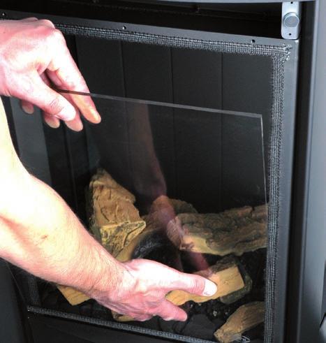
10 Place the baffle (see Appendix 4, Fig. 4); Use the template supplied to set the distance of the restriction (see Appendix 4, Fig. 5) as follows: - A distance of 33 mm means that the baffle is closed to a maximum level; - A distance of 40, 50 and 65 mm is set by using a template. Fix the baffle by using the socket cap screw (S) Air inlet guide (L) The air inlet guide (L) is supplied separately. Follow the procedure below for installing the air inlet guide (see Appendix 4, Fig. 6): Remove the front pane as indicated in section 6.9.1; Remove the tray surrounding the burner (M) from the appliance; Place the air inlet guide; Place the tray surrounding the burner (M) back in the appliance.!caution Do not throw away the air inlet guides, you may need them in the future. Caution 6.8 Placing the wood set The appliance is supplied with a wood set. Strictly observe the following instructions to prevent unsafe situations: - only ever use the supplied wood set; - place the wood set exactly as described; - make sure the pilot burner and the space around it are kept free from objects (see Appendix 4, Fig. 7); - make sure that the slot between the burner tray and the tray surrounding the burner is kept free from objects. - make sure that the vermiculite s fine dust does not get on the burners Wood set The wood set consists of vermiculite (see Appendix 4, Fig. 8), chips (see Appendix 4, Fig. 9) and a number of blocks. Fill the burner tray with vermiculite; equally spread the vermiculite (see Appendix 4, Fig. 14).!Caution - You can influence the flame image by moving the vermiculite, yet - the burner deck has to remain covered with vermiculite in order to prevent that the life expectancy of the burner is reduced Fill the tray around the burner with chips; equally spread the chips. Caution Do NOT place chips over the slot, around the burner. Identify blocks A up to F by using Fig. 10, see Appendix 4.!Tip Use the burn stains on the blocks for identification. First place blocks A and B (see Appendix 4, Fig. 11). Caution - Place block A in such a way that the pilot flame and flame opening are not covered. Fig. 11, see Appendix 4, shows how it should be done, and Fig. 12, see Appendix 4, shows how it should not be done Then place blocks C up to F (see Appendix 4, Fig. 13). Caution The logs should not completely cover the burner pattern, because: - the main burners will not ignite properly; which could result in unsafe situations; - the appliance will become filthy more quickly, as a result of soot; - the flame picture will be affected. 6.9 Panes Front pane After placing the wood set you can place the front pane as described below.!caution - Avoid/remove fingerprints on the pane, as they will burn into the glass. - Avoid damages when removing/placing the glass pane. - Make sure the sealing tape at the edges of the glass pane is not damaged during removal Removing the front pane When removing the front pane, you should observe the instructions below; (see Appendix 4, Fig. 15 to 18) Open the door; Unscrew the 6 parkers of the glass strip at the sides by using the socket spanner supplied; Remove the glass strips; Unscrew the 3 parkers of the upper glass strip; Hold the pane and remove the upper glass strip; Remove the pane from the slot at the underside Placing the front pane Placing the front pane will take place in reverse order of the removal procedure described above.!caution Do not screw the parkers on too tight, to prevent breaking and/or slipping: tight=tight. 10
11 6.9.2 Side panes The side panes should be removed in case of torn or broken panes Removing the side pane Follow the steps below for removing: Carefully remove the top plate from the appliance, so that the lacquered pipe piece will not be damaged. The top plate is loose; Slide the housing upwards at the side (see Appendix 4, Fig. 19); Remove this part of the housing; Unscrew the 3 parkers at the top by using the socket spanner; Hold the pane and remove the glass strip; Remove the pane from the slot at the underside Placing the side pane Placing the side pane will take place in reverse order of the removal procedure described above.!caution Do not screw the parkers on too tight, to prevent breaking and/or slipping: tight=tight. 7. Wireless remote control The appliance is supplied with a wireless remote control. Ignition, controlling the flame height and switching off are performed by a remote control that operates a receiver in the control box. User Manual, chapter 4, Command/control, describes the operation of the appliance including the way the remote control works.!caution Do not ignite the appliance before the gas and discharge connections have been fully installed, first observe the procedure described in chapter 8.3.!Tip!Tip Below, we will describe how the receiver is connected. 7.1 Receiver The receiver should be connected to the appliance, before the batteries are installed. Follow the procedure below (see Appendix 4, Fig. 21): Slide the brown plug of the connecting cable onto the back of the receiver s printed circuit board. Connect the white plug to the gas control block. The plugs have different sizes that correspond with the connectors. Connect the cables of thermocouple 1 to the receiver; (see Appendix 4, Fig. 21, arrow B). - The size of the eye corresponds with the size of the screw; - The colours of eye and screw also correspond. Connect the ignition cable to the receiver; (see Appendix 4, Fig. 21, arrow A). Connect power: a) When using batteries, see section below; b) When using an adapter: - connect it to the receiver; (see Appendix 4, Fig. 21, arrow C); - insert the plug into the wall socket. Place the receiver in the control box, as indicated on Fig. 22 (o), see Appendix 4. Bend the antenna out of the clips; see Appendix 4, Fig. 21, arrow D and Fig. 22. Set the antenna straight.!caution - Do not place the antenna too close to the ignition cable and/or metal parts (for the correct position, see Appendix 4, Fig. 22); - Do not place the ignition cable over and/or along metal parts: this will weaken the spark; - Do not lay the ignition cable over the receiver. this could damage the receiver; - Avoid dust on or in the receiver: cover it when performing work. 11
12 7.1.1 Placing / replacing the batteries Follow the procedure below when placing the batteries: Open the door of the stove. Pick up the receiver. Slide the cover off. Place or remove the 4 penlite (AA type) batteries.!caution - Avoid a short circuit between the batteries and metal objects/parts; - Observe the + and - poles of the batteries and the holder; - Use alkaline batteries. Slide back the cover. Place back the receiver.!caution Batteries are regarded as small chemical waste and may therefore not be disposed with the household rubbish. 7.2 Setting the communication code Prior to putting the application into operation, a communication code must be set between the remote control and the receiver. If the receiver or the remote control are replaced, a new code will have to be set. Follow the procedure described below: If necessary, place the batteries in the receiver s battery holder; see section If necessary, place the 9V block battery in the remote controle; see User Manual. Small Flame Hold down the reset button on the receiver, until you hear two consecutive sound signals (see Appendix 4, Fig. 24). Large Flame After the second, longer signal, let go of the reset button. Press the small flame button on the remote control for 20 seconds, until you hear two short sound signals: this is the confirmation of a good communication. 7.3 Alternative operation Appliances made with an electronic ignition and radio remote control can be connected to an alternative external control system (e.g. Domotics). For this purpose, there are 4 connection points at the side of the receiver (see Appendix 4, Fig. 20). For connecting an external control unit, you will need a Domotics connection cable for GV60. Consult DRU s service website. The following contacts are possible: - Ignition: connect both contacts 1 + 3, for one second (if there is a 2nd thermocouple, the appliance should burn at full power for at least 20 sec. before the required position can be chosen). - Flame high(er): briefly close contact 1 once per step, or 12 seconds for the highest position. - Flame low(er) until switch-off (pilot flame remains on): briefly close contact 3 once per step, or 12 seconds for the lowest position. - Completely switching off the appliance (pilot flame included): close all three contacts , for one second. The appliance will always continue to respond to the radio remote control supplied with it. The external control system is able to use one of the two modes of this remote control. 1. Manual mode This mode of the remote control is passive and will not take any action unless it is operated. The external control system is able to control the functions for high/low position, ignition and switching off.!tip If the external control system has an intelligent clock function and/or thermostat function, the remote control supplied with the appliance should have the manual mode in order to prevent interruption of these functions. 2. Clock/thermostat mode This mode of the remote control is active and will be responsible for the clock function and thermostat function. The external control system is able to control the functions for high/low position, ignition and switching off.!tip - If the appliance is switched off (the pilot flame included) manually or by one of the safeguards, ignition of the appliance will be blocked for a period of 3 minutes for reasons of safety. - If it is no longer possible to operate the appliance with the external control system, you must switch it off and then switch it on again with the supplied remote control. 12
13 8. Final check In order to check whether the appliance is working properly and safely, you must perform the following checks before the appliance is used. 8.1 Gastightness Caution All connections must be gastight.!caution The gas control block can be subjected to a maximum pressure of 50 mbar. Check the connections for gastightness. 8.2 Gas pressure / pre-pressure The burner pressure is set at the factory; see type plate. It is not necessary to check the burner pressure. The pre-pressure in house installations, however, should be checked, as they can vary. Check the pre-pressure; see Appendix 4, Fig. 23 for the measuring nipple on the gas control block; Contact the gas company if the pre-pressure is not correct. Caution 8.3 Ignition pilot and main burner For igniting the pilot and main burner, see the User Manual, chapter 4, Operation. Always wait 5 minutes after the pilot flame has gone out, before you re-ignite the appliance First ignition of the appliance after installation or adjustments!caution After installation, or after work has been performed, you should ignite the appliance for the first time without the glass window. If necessary, bleed the gas pipe. Follow the procedure described below: If required, remove the glass window; Start the ignition procedure according to chapter 4 in the User Manual; If the pilot flame does not ignite: - repeat the ignition procedure until the pilot burner ignites; - consult the malfunction search diagram (Chapter 11) if this does not happen after a few attempts; After igniting the pilot flame, the main burner will ignite during the ignition procedure; Check whether the main burner continues to burn; If the main burner does not continue to burn: - repeat the ignition procedure until the main burner continues to burn - consult the malfunction search diagram (Chapter 11) if this does not happen after a few attempts; Switch off the appliance; Clean the glass pane before using it for the first time, as described in the user manual. Then mount the glass pane as described in section 6.9. Repeat the ignition procedure a few times and perform the checks described in chapter 8.3.2; From now on, the pilot flame should ignite smoothly. Clean the glass pane after burning for the first time, as described in the user manual.!caution - During the ignition process, you are not allowed to operate control button B on the gas control manually. - Always wait 5 minutes after the pilot flame has gone out, before you re-ignite the appliance. - You are not allowed to turn the pilot flame lower by using the settings on the gas control Main burner!caution - The pilot burner should ignite the main burner within a couple of seconds, and without popping. - The main burner(s) must cross the full burner smoothly and without popping and continue to burn.!tip Check operation of the main burner from a cold condition (pilot flame off): After opening the gas valve, the main burner should burn within a few seconds. When the gas valve is opened, the motor will start to run; this is audible. The flame picture and a good flame transfer can only be properly judged if the glass window is installed. Use the malfunction search diagram (Chapter 11) if the ignition of the main burner does not comply with the abovementioned requirements. 13
14 8.4 Flame picture The flame picture can only really be assessed when the appliance has been burning for several hours. Volatile components from paint, materials, etc., which evaporate in the first hours, will affect the flame picture. Check whether the flame picture is acceptable. Consult the malfunction search diagram (Chapter 11) if the flame picture is not acceptable. 9. Maintenance Once a year the appliance should be checked, cleaned and, if necessary, repaired by a competent installer in the field of atmospheric gas heating. Check at least whether the appliance is working properly and safely. Caution - Close the gas tap when performing maintenance work; - Check the gastightness after repair; - After replacing the thermocouple you should first tighten the swivel of the gas control block by hand and then give it another quarter turn with a suitable spanner. - SS-absolutely do not clean the concentric system (internally) with a steel brush or metal sponge, for example. This will damage the oxide skin and could lead to leaks in the system as a result of pitting corrosion. If required, clean the following components: - the pilot flame burner; - the combustion room; - the panes.!caution Only clean a glass pane once it has reached room temperature.!caution - Avoid damage to the glass pane(s). - Avoid/remove fingerprints on the glass pane(s), as they will burn into the glass. - Clean the glass pane(s) as described in the user manual. - Regularly remove accumulated dirt, as it can burn into the glass. - Do not use the appliance when a glass pane is broken and/or cracked, until it has been replaced as described from section 6.9 Caution - If necessary, place back the wood set correctly; see section 6.8. Inspect the flue gas discharge / combustion air supply system;!caution You must always perform a final inspection. Perform a check as described in chapter 8. Parts requiring replacement can be obtained from your supplier. 10 Delivery You must explain to the user how he should operate the appliance. You should instruct her/him for instance on using the appliance for the first time, the operation of the remote control, annual maintenance. Caution - Tell the user to close the gas tap immediately in case of malfunctions/bad performance and contact the installer in order to prevent dangerous situations; - Indicate the location of the gas tap; - Point out the precautions in the user manual against unintended ignition by other wireless remote controls such as car keys and garage door openers. Instruct the user about the appliance and the remote control. When the appliance is started for the first time, point out that - when the appliance is stoked up for the first time, volatile components evaporate from paint, materials, etc.; - when evaporating the appliance should preferably be set at the highest level; - the room should be well ventilated. Give the user manual and installation manual to the user (the installation manual should be kept near the appliance). 14
15 11. Storingen Malfunction search diagram atmospheric gas-fired heating appliance with electronic ignition: Starting up cycle. Start 1.01 Does receiver beep? no yes 1.03 One long 5 second beep, (possibly preceded by 7 short beeps). no 1.05 Short sound signals, 1 sec after each other, followed by the clicking noise of the gasvalve opening. yes yes no 1.02 Receiver - Batteries missing or empty. Replace by 4x AA. After replacing batteries: short beep. No beep: receiver defective. Replace by new one. - Replace rechargeables by alkaline batteries. - Communication code between remote and receiver has to be (re)set: - Press reset button on receiver until brief beep, followed by long beep. - Release reset button and press flame low button on remote within 20 seconds. Then 2 short beeps and brief noise of servomotor to confirm that communication code was set succesfully Controleer: All appliances - 8 wire cable between receiver and gas control not connected, poor contact or one wire loose in connector (check by pulling wire by wire). - Wiring of thermocouple circuit interrupted, or poor contact. Check thermocouple, thermocouple interrupter and wiring. Sie box Microswitch on gascontrol defective swift beeps 1 sec after each other when motor turns or 3 brief short beeps within 1 sec at end of ignition cycle. yes 1.07 Replace batteries Measure battery voltage: <5.5V: replace preventative. <4.8V: appliance works no longer. Replace batteries. Turn two pages backwards and continue with box Remote control - Battery 9V empty (see indication on display). Several - After switching off/going out the remote set is locked for 120 sec. (older versions 60 sec). Wait 2 minutes before reigniting. 15
16 Fires with electronic ignition, fault finding: Ignition and burning Start 2.01 Can pilot be lit? no yes 2.06 Pilot can be lit. Does it stay alight? yes 2.08 Does main burner ignite immediately? yes 2.10 Do(es) main burner(s) ignite smoothly and across its/their full length after first ignition by pilot burner? yes 2.02 Sparking? yes 2.03 Only one spark? no 2.04 Check: Receiver - Replace missing, weak or rechargeable batteries (not enough power to open thermoelectric valve). Presence of gas on pilot burner Check pilot on presence of gas at normal ignition cycle or in Manual Mode (turn oval knob on gas control to MAN and keep safety shut off valve opened with a screwdriver) and ignite pilot with a lighter. - Pilot flame not on: Step 1. - Pilot flame on: Step 2. Step 1: Pilot has no gas Check: - Gas tap open? - Gas at gas control (line pressure at measuring point on gas control). - Gas flowing out of gas control? (by loosening pilot tube at gas control). If not: check adjustment screw pilot flame (under black cover): sealing not to be broken. Sealing broken: screw should be fully open. - Blocking of pilot tube (kink or dirt). - If this does not help: replace gas control. Step 2: Pilot has gas, but no ignition - Electrode with 90 bended tip: bend tip 1 mm higher. - Spark too weak (thin and reddish). Act as if no spark in box 2.05 and perform actions described for ignition cable and ignition electrode. - Pilot flame too weak (dirty). Remove injector (remove gland nut and the pilot tube). See that it does not fall away. Clean with compressed air. Rectify. Retry. no yes 2.03a - Loosen and retighten earthing screw on gas control. - If this does not work: replace receiver Check: Ignition cable - Present and connected. - Being free from metal parts or concrete. - Too long: cut away all excessive length at receiver end, and reconnect. - Shorting out to earth: replace ignition cable. - Spark in wrong position: - slide rubber sleeve on ignition cable over ceramic of electrode. - Replace electrode if neccessary. Ignition electrode - Straight electrode: - oxidation (roughen electrode with file or sand paper); - position (4 mm from pilot burner). - Cracks in ceramic (not always visible): replace electrode. Starting procedure After switching off/going out the remote is locked for 120 sec. (older versions 60 sec). Wait 2 minutes before reigniting.. no 2.07 Pilot out when servomotor starts to run? Check the thermocouple system. - Measure thermocouple voltage in mv just after servomotor starts to run and the voltage goes down. - Measure between red dot on receiver and earth point on gas control (see Appendix 4, Fig. 25). - 0 mv mv mv - 6 mv and higher - Requirement: after rectification actions thermocouple voltage should be 6 mv at least, just after motor starts running! Voltage 0 mv - Thermocouple defective. Check by replacing or measuring voltage at end whilst heating (tip: with a lighter). - Short circuiting or interruptions in circuit: Check: - thermocouple tight in interruptor; - interruptor tight in gas control; - black wires (yellow/red end) connected to interruptor + receiver; - interruptor (mount thermocouple directly in gas control and ignite in Manual Mode (see 2.04). If pilot stays on: interruptor defective. Voltage 2-3 mv - Check pilot flame. Too small: - pilot dirty. Clean up (see 2.04). - check for pilot gas tube tightness; - pilot tube kinks or dirt inside; - line pressure too low. - Tip: thermo couple not in (correct!) pilot flame. Bend into flame. Voltage 3-5 mv - Appliance may work, but is too critical. Perform actions as described for 2-3 mv. no 2.09 Ignition procedure - Oval knob on gas control is on MAN. Set to ON and restart. Retarded ignition of main burner(s) Gas to main burner opens ca. 3-5 seconds after servo motor, operating the gas valve, starts running (sound of motor!). After this the main burner is to ignite (at least partially) within 10 seconds and not with a firm noise WHOOF. If not: no or delayed cross lighting of main burner. Hazardous situation. Stop ignition procedure straight away and first check for: - Position of logs or pebbles. - Burner holes (locally) blocked. Remove vermiculite dust. - Vermiculite missing. - Chips on burner. - Vermiculite not distributed evenly across burner(s). no 2.11 No proper cross lighting of main burner(s). - Go to box 2.09 and take actions act as described for retarded ignition of main burner. Voltage 6 mv and higher Voltage OK, so different cause. - Receiver defective. Check by dismounting black-red and yellow control cables from receiver and link together. Ignite fire in Manual Mode (see 2.04). Pilot stays on: receiver defective. - Gas control defective if receiver is not defective. Replace gas control. 16
17 yes no yes yes 2.12 Does main burner go out 2.14 Is flame picture OK? 2.16 Can fire be switched off? after some time? 2.18 Perfect! You have a well functioning fire yes no no 2.13 Check Gas supply - Supply pressure does not drop away as main burner (or other appliance) lights, causing pilot flame to shorten. - Burner pressure (too high or too low). Flames instable (suffocating, lack of air). Dancing flames on burner. Lack of combustion air. Check: - flue system permissible; - proper flue terminal used, make should be DRU ; - terminal correctly sited on roof or wall relative to obstructions; - integrity of flueing system (no interruptions, not barred, cobwebs); - air inlet guides; - flue restrictor/damper; - throttle rings. See manual for specific requirements Check Flames: too low - Supply pressure does not drop away as main burner or other appliances in the building light, causing flames to shorten. - Burner pressure (too low). - False air: Check soundness glass window gasket/ soundness of the connection of the glass panes of two/three sided appliances (no slots allowed). Flames: too high - Line pressure. - Burner pressure. Flames: no even distribution or out on part of the burner(s) - Position of logs or pebbles. - Burner holes (locally) blocked. Remove vermiculite dust. - Vermiculite not distributed evenly across burner(s). - Adjustment of throttle ring(s) Replace gas control (thermo-electric valve does not shut down quick enough because of some permanent magnetism). Pilot burner - Pilot burner dirty. Weak pilot flame being drawn away by flames main burner. Clean with compressed air. See Flames: too blue/too yellow or sooting - Air inlet guides. - Flue restrictor/damper. - Adjustment of throttle ring(s). Flames: suffocating: lack of air - You see dancing flames on burner, seeking for air. See Flame picture restless Indication of too much draught. Check: - adjustment of appliance damper and air inlet guides); - vertical flue length allowed (<12 m); - window glass not mounted gas tight. 17
18 Appendix 1 Parts included with the delivery In the following table you can find the parts that are supplied with the appliance. Table 5: Parts included with the delivery Part Quantity Wood set 1x Installation manual 1x User manual 1x Setting template for baffle 1x Baffle 1x Air inlet guide 1x Spare parkers for mounting the front pane Socket spanner 1x Remote control with receiver 1x 9V block battery 1x Penlite battery (AA type) 4x Squeeze coupling 15 mm x G3/8 1x 18
19 Appendix 2 Technical data In the following table you can find the technical data. Table 6: Technical data Model identifier(s): Trio RCE Type of appliance Free-standing Combustion Closed combustion Type C11, C31, C91 Category I 2EK, I 2ELL, I 2H, I 2E+, I 2E Concentric appliance connection 150/100 Applicable concentric systems Flame protection version 2nd thermocouple safety Atmosphere safety Explosion hatch DRU LAS ES-E 200/150/100 DRU LAS ES-I 150/100, DRU LAS AG-I 150/100 Pilot flame with thermocouple Yes No Yes Gastype Symbol G25/G25.3* G20 Unit Indirect heating functionality No No Direct heat output 4,2 4,5 kw Indirect heat output - - kw Space heating emissions NO X 99,0 90,2 mg/kwh input (GCV) Heat output Nominal heat output P nom 4,2 4,5 kw Minimum heat output (indicative) P min 1,8 2,0 kw Technical data Nominal heat input (Hs) 6,0 6,6 kw Nominal heat input (Hi) 5,4 5,9 kw Consumption max 658,0 620,0 L/h Consumption min 380,0 355,0 L/h Burner pressure max 24,5 19,5 mbar Burner pressure min 8,1 6,7 mbar Main burner injector 1x Ø1,20 1x Ø1,40 1x Ø1,20 1x Ø1,40 Low setting injector 1,6 1,6 mm Efficiency class (EN613) 1,0 1,0 Useful efficiency (NCV) Useful efficiency at nominal heat output η th,nom 87,4 85,4 % Useful efficiency at minimum heat output (indicative) η th,min 81,7 83,0 % Auxiliary electricity consumption At nominal heat output el max - - kw At nominal heat output el min - - kw In standby mode el SB - - kw Permanent pilot flame power requirement mm Pilot flame power requirement (if applicable) P pilot - - kw Energy efficiency Energy efficiency index EEI Energy efficiency class B B Type of heat output / room temperature control Single stage heat output, no room temperature control Two or more manual stages, no room temperature control With mechanic thermostat room temperature control With electronic room temperature control With electronic room temperature control plus day timer With electronic room temperature control plus week timer Other control options Room temperature control, with presence detection Room temperature control, with open window detection With distance controle option No No No Yes Yes Yes*** Yes*** Yes*** Yes*** * This appliance is suitable for G25.3 with the composition according NTA ** System efficiency *** Is applicable using domotics. 19
20 Appendix 3 Parts Parts can be ordered through 20
21 Appendix 4 Figures c-1218/ Fig. 1 21


22 1x90 Fig m 38c-744f Fig. 2 max. 3m Fig. 4 Fig. 5 Fig. 6 22


23 Fig. 7 Fig. 8 Fig. 9 Fig


24 TRIO 24 Fig. 11 Fig. 12 Fig. 13 Fig I N S T R U C T I O N F O R I N S TA L L AT I O N


25 Fig. 15 Fig. 16 Fig. 17 Fig. 18 Fig

26 Fig. 20 Fig


27 B A 38p-0181 O 38C-2031/1 Fig. 22 Fig p-0182 Fig p-0179 Fig. 25 5mV 27
User manual (GB / IE) for appliances provided with an electronic ignition on the remote control. English. Read this document and store it carefully
 for appliances provided with an electronic ignition on the remote control. English. Read this document and store it carefully") User manual (GB / IE) for appliances provided with an electronic ignition on the remote control Read this document and store it carefully 958.007.07.uk 1 UK Contents page Preface 2 1. Introduction 3 2.
User manual (GB / IE) for appliances provided with an electronic ignition on the remote control Read this document and store it carefully 958.007.07.uk 1 UK Contents page Preface 2 1. Introduction 3 2.
PowerVent. Installation manual (GB) English. Store this document in a safe place UK
 English. Store this document in a safe place UK") PowerVent Installation manual (GB) Store this document in a safe place 959.034.03.UK GB Contents Blz Foreword 3 1. Introduction 3 2. CE declaration 4 3. SAFETY 4 3.1 General 4 3.2 Regulations 4 3.3 Precautions
PowerVent Installation manual (GB) Store this document in a safe place 959.034.03.UK GB Contents Blz Foreword 3 1. Introduction 3 2. CE declaration 4 3. SAFETY 4 3.1 General 4 3.2 Regulations 4 3.3 Precautions
Metro 130 XT Metro 130 XT Tunnel
 Metro 130 XT Metro 130 XT Tunnel G20/G25/G31 Installation manual (G/IE) Store this document in a safe place 959.041.00. DRU15798-112731-EN--0113-2 INSTLLTION MNUL ontents 1. Introduction 2. E declaration
PowerVent. Installation manual (GB) English. Store this document in a safe place UK
 English. Store this document in a safe place UK") PowerVent Installation manual (GB) Store this document in a safe place 959.078.00.UK GB Contents page Foreword 3 1. Introduction 3 2. CE declaration 4 3. SAFETY 4 3.1 General 4 3.2 Regulations 4 3.3 Precautions
PowerVent Installation manual (GB) Store this document in a safe place 959.078.00.UK GB Contents page Foreword 3 1. Introduction 3 2. CE declaration 4 3. SAFETY 4 3.1 General 4 3.2 Regulations 4 3.3 Precautions
PowerVent Installation manual. English. Store this document in a safe place EN
 PowerVent - 02 Installation manual Store this document in a safe place 959.114.01.EN en Contents Page Foreword 3 1. Introduction 3 2. CE declaration 4 3. SAFETY 4 3.1 General 4 3.2 Regulations 4 3.3 Precautions
Circo G20/G25/G31. Installation manual (GB/IE) English. Store this document in a safe place DRU EN
 English. Store this document in a safe place DRU EN") irco G20/G25/G31 Installation manual (G/IE) Store this document in a safe place 959.044.01. DRU15798-175417-EN--0213-2 INSTLLTION MNUL ontents 1. Introduction 2. E declaration 3. SFETY 3.1 General 3.2
irco G20/G25/G31 Installation manual (G/IE) Store this document in a safe place 959.044.01. DRU15798-175417-EN--0213-2 INSTLLTION MNUL ontents 1. Introduction 2. E declaration 3. SFETY 3.1 General 3.2
Circo RCE G20/G25/G25.3/G31. Installation manual. English. Store this document in a safe place DRU EN-US
 irco RE G20/G25/G25.3/G31 Installation manual Store this document in a safe place 959.044.02.UK DRU-175417-EN-US-1017-4 EN INSTLLTION MNUL ontents 1. Introduction 2. E declaration 3. SFETY 3.1 General
Metro 70 - Metro 70 Tunnel
 Metro 70 - Metro 70 Tunnel G31 propane Instructions for installation (GB / IE) Please retain this document carefully UK Contents page Foreword 2 1. Introduction 3 2. EC Declaration of Conformity 3 3. SAFETY
Metro 130XT 41 RCH Metro 130XT Tunnel 41 RCH
 Metro 130XT 41 RH Metro 130XT Tunnel 41 RH G20/G25/G25.3 (Natural gas) G31 (Propane) Installation manual Store this document in a safe place 959.073.02.EN DRU-667777-EN-US-1017-3 EN ontents 1. Introduction
Fyn Installation guide
 Fyn 450 400100929-1114 ENG Installation guide ENG 1.1 1.2 A B 1.3 1.4 1 < < < < 2.1 2.2 2.3 3.1 3.2 2 < < < < 4.1 4.2 4.3 4.4 3 < < < < Table of contents 1 Introduction... 6 2 Safety instructions... 6
Clear Installation guide
 Clear 40010631-0938 ENG Installation guide ENG 1.1 1.2 1.3 A 1.4 1.5 1 < < < < A B 2.1 2.2 2.3 C 2.4 2.5 2 < < < < 3.1 3.2 3-3 3 < < < < Inhoudsopgave 1 Introduction... 6 2 Safety instructions... 6 3 Installation
Duet XL /0929. Installation guide
 Duet XL 40010749/0929 ENG Installation guide ENG 1.1 1.2 1.3 1.4 1.5 A 1.6 1.7 1 < < < < B A 2.1 2.2 2.3 2.4 2 < < < < 2.5 2.6 2.7 2.8 3 < < < < 3.1 F F 3.2 3.3 4 < < < < Table of contents 1 Introduction...
Paco RCH. G20/G25/G25.3 Natural gas. Installation manual (UK/IE) English. Store this document in a safe place DRU EN-US
 English. Store this document in a safe place DRU EN-US") Paco RH G20/G25/G25.3 Natural gas Installation manual (/IE) Store this document in a safe place 959.098.01. DRU-680093-EN-US-0916-2 ontents 1. Introduction 2. E declaration 3. SFETY 3.1 General 3.2 Regulations
Paco RH G20/G25/G25.3 Natural gas Installation manual (/IE) Store this document in a safe place 959.098.01. DRU-680093-EN-US-0916-2 ontents 1. Introduction 2. E declaration 3. SFETY 3.1 General 3.2 Regulations
Fyn Installation guide
 Fyn 600 4001131-1123 ENG Installation guide ENG 1.1 1.2 A B 1.3 1.4 1 < < < < 2.1 2.2 2.3 2.4 3.1 3.2 2 < < < < 4.1 4.2 4.3 4.4 3 < < < < 1 Introduction The appliance can only be installed by a competent
INSTALLATION AND MANINTENANCE INSTRUCTIONS
 INSTALLATION AND MANINTENANCE INSTRUCTIONS Appr. Nr. A 9503 T - 0085 AQ 0765 PEGASUS F2 T HIGH EFFICIENCY GAS-FIRED CAST-IRON BOILERS Models 51-68 - 85-102 2 Contents 1. General technical data 2. Dimensional
Solution Installation guide
 Solution 40011444-1327 ENG Installation guide ENG 1-1 1-2 1-3 1.4 1 < < < < 2.1 2-3 2-4 2 < < < < 3-1 3.2 3-3 3.5 3.6 3 < < < < 4-1 A 4-2 4-3 4 < < < < Dimensions Terminal position Distance (For good working
Vaska Logburner. voorbeeld Installation guide
 Vaska ogburner voorbeeld 40010627-2103 ENG Installation guide ENG 1.1 1.2 1.3 1.4 1.5 1 < < < < 1 Introduction The appliance can only be installed by a competent person in accordance with the Gas Safety.
CRYSTAL FIRES. Inset Conventional Flue Fire. (BOSTON/MIAMI) Cf1 and MANHATTAN USER INSTALLATION AND SERVICING INSTRUCTIONS
 Cf1 and MANHATTAN USER INSTALLATION AND SERVICING INSTRUCTIONS") CRYSTAL FIRES (BOSTON/MIAMI) Cf1 and MANHATTAN Inset Conventional Flue Fire USER INSTALLATION AND SERVICING INSTRUCTIONS FOR USE WITH NATURAL GAS G20 @ 20 mbar For use in GB and IE CE THESE INSTRUCTIONS
CRYSTAL FIRES (BOSTON/MIAMI) Cf1 and MANHATTAN Inset Conventional Flue Fire USER INSTALLATION AND SERVICING INSTRUCTIONS FOR USE WITH NATURAL GAS G20 @ 20 mbar For use in GB and IE CE THESE INSTRUCTIONS
HG 675 CX 60 HG 675 CN 60 HG 675 CW 60
 HG 675 X 60 HG 675 CX 60 HG 675 CN 60 HG 675 CW 60 1 2 1. : 93/68: 90/396: 2006/95/CE: 2004/108/CE: - 1935/2004:. 2002/95/CE: RoHS 2.,.,,,,...,. (,..)..,,.,. ( ),,, ;,,.,.....,.,,,,,,...,. (..),,.,..,.,,,,
Servicing manual. Wall-mounted condensing gas boiler 600 Series - 11S / 19S / 24S / 24C /2002 GB(EN) For trade use
 For trade use") GB122 7210 1300-12/2002 GB(EN) For trade use Servicing manual Wall-mounted condensing gas boiler 600 Series - 11S / 19S / 24S / 24C Please read thoroughly before attempting to diagnose fault List of contents
GB122 7210 1300-12/2002 GB(EN) For trade use Servicing manual Wall-mounted condensing gas boiler 600 Series - 11S / 19S / 24S / 24C Please read thoroughly before attempting to diagnose fault List of contents
Servicing manual. 600 Series - 11S / 19S / 24S / 24C. Wall-mounted condensing gas boiler. For trade use
 GB122 Servicing manual Wall-mounted condensing gas boiler 600 Series - 11S / 19S / 24S / 24C For trade use Please read thoroughly before attemting to diagnose fault 7217 4900 (03/2010) GB/IE List of contents
INSTALLATION & USERS INSTRUCTIONS. FOR USE WITH NATURAL GAS 20 mbar For use in GB and IE
 1 valentine s buildings Bechers drive Aintree racecourse Business Park L9 5ay CF1 L GAS APPLIANCE INSET CONVENTIONAL FLUED GAS FIRE INSTALLATION & USERS INSTRUCTIONS FOR USE WITH NATURAL GAS G20 @ 20 mbar
F900 SERIES GAS CHARGRILL G9440, G9460, G9490, G User, installation and servicing instructions T Read these instructions before use
 F900 SERIES User, installation and servicing instructions GAS CHARGRILL G9440, G9460, G9490, G94120 Read these instructions before use DATE PURCHASED: MODEL NUMBER: SERIAL NUMBER: DEALER: SERVICE PROVIDER:
Respect OC Installation manual
 Respect OC 40011335-1235 ENG Installation manual ENG 1.1 1.2 A 1.3 1.4 A A 2.1 2.2 2.3 1 < < < < 2.4 2.5 B C A B A 2.6 2 < < < < 3.1 3.2 3.3 3.4 3.5 3.6 3 < < < < A B 3.7 4 < < < < L A A 4.1 A A 4.2 A
Gas Instantaneous Water Heater
 6 720 607 823 GB (06.06) SM Installation and Operating Instructions Gas Instantaneous Water Heater WR10..B... WR11..B... With electronic ignition and triple safety system consisting of ionisation detector,
FLAME HEATER PYRAMID CLFH-10SS OPERATION INSTRUCTIONS
 FLAME HEATER PYRAMID CLFH-10SS OPERATION INSTRUCTIONS www.colorato.net For outdoors use only Uses propane, butane or LPG only Reflector: 47x47 mm Total Height: 2250 mm Regulator s external pressure: 28-30
Maestro 80-2 RCH Maestro 80-3 RCH
 Maestro 80-2 RH Maestro 80-3 RH G20/G25/G25.3 (Natural gas) G31 (Propane) Installation manual (/IE) Store this document in a safe place 959.094.04. DRU-677279-EN-US-1016-5 INSTLLTION MNUL ontents 1. Introduction
IDE 20 / IDE 30 / IDE 50 IDE 60 / IDE 80
 IDE 20 / IDE 30 / IDE 50 IDE 60 / IDE 80 EN OPERATING MANUAL OIL HEATER TRT-BA-IDE20-30-50-60-80-TC-001-EN Table of contents Information on the use of this manual... 1 Scope of delivery... 1 General safety...
Dovre 250 Cast Iron Gas Stove
 Dovre 50 Cast Iron Gas Stove NATURAL GAS AND LPG INSTALLATION, SERVICING AND USER INSTRUCTIONS THIS PRODUCT IS FOR USE ONLY IN GREAT BRITAIN AND IRELAND These instructions are to be left with the customer,
Gas Fire Patio Heater Q9
 Gas Fire Patio Heater Q9 Instruction Manual Please read the manual BEFORE you unpack or install the fire TABLE OF CONTENTS Warning 3 Getting Started 4 What s Included 5 Assembly Procedures 6 Product Drawing
JUNEAU JUN. 08/51193/0 Issue 0
 JUNEAU JUN 08/51193/0 Issue 0 The product complies with the European Safety Standards EN60335-2-30 and the European Standard Electromagnetic Compatibility (EMC) EN55014, EN60555-2 and EN60555-3 These cover
Proline GAS HOB Model TCG40IX Instruction Book
 Proline GAS HOB Model TCG40IX Instruction Book GB Operating and Installation Instructions Index Technical data and specifications...... 3 Installation...................... 3-6 Ventilation........................
CLASSIC II QUATTRO DECORATIVE FUEL EFFECT APPLIANCES FOR USE WITH NATURAL GAS IIN INSTALLATION, SERVICING & USER INSTRUCTIONS
 CLASSIC II QUATTRO DECORATIVE FUEL EFFECT APPLIANCES FOR USE WITH NATURAL GAS IIN INSTALLATION, SERVICING & USER INSTRUCTIONS THESE INSTRUCTIONS MUST BE LEFT WITH THE USER MANUFACTURED BY: MULTIGLOW FIRES
16 Ultiflame Inset Electric Fire
 16 Ultiflame Inset Electric Fire B-1001645 Packing Checklist Electric Fire Remote Control Handset 2 x AAA Batteries Log Set Ember Ice Set Instruction Manual Fascia IMPORTANT PLEASE READ THESE INSTRUCTIONS
Relaxed Premium M Relaxed Premium M ENG
 Relaxed Premium M 40010959 1440 Relaxed Premium M ENG 3 alternative finishes. 1.1a 1.1b 1.1c 1 < < < < 1.2 1.3 7 1.4 2 < < < < 1.5 1.6 B 1.9 3 < < < < 2.1 2.2 2.3 3.1 3.2 3.3 3.4 4 < < < < 3.5 4.1 4.2
Decorative Fuel Effect Appliances
 Decorative Fuel Effect Appliances Technical Manual User and Installation Instructions for CUBB22US Available in Natural Gas. 1 Contents Section Pages 1 Unpacking 3 2 Installation Parameters 4 3 Installation
Gas Fire Patio Heater Lhotse-817
 Gas Fire Patio Heater Lhotse-817 Instruction Manual Please read the manual BEFORE you unpack or install the fire TABLE OF CONTENTS Warning 3 Getting Started 4 What s Included 5 Assembly Procedures 6 Product
IMPORTANT SAFETY INSTRUCTIONS DANGER: WARNING:
 IMPORTANT SAFETY INSTRUCTIONS YOUR SAFETY AND THAT OF OTHERS IS PARAMOUNT This manual and the appliance itself provide important safety warnings, to be read and observed at all times. This is the attention
USHO COOKER INSTALLATION INSTRUCTIONS SAFETY INSTRUCTIONS USER INSTRUCTIONS MODEL: USHO. INSTRUCTION REF: IN152 ISSUE No. 4 DATE
 Page 1 of 11 INSTALLATION INSTRUCTIONS SAFETY INSTRUCTIONS USER INSTRUCTIONS USHO COOKER MODEL: USHO Page 2 of 11 WARNING To avoid scratching the highly polished exterior surface of this equipment whilst
VASKA B11. gas -fireplace installation guide
 VASKA B11 gas -fireplace installation guide Saturnus 8 NL-8448 CC Heerenveen Postbus 219 NL-8440 AE Heerenveen T. +31(0)513 656500 F. +31(0)513 656501 40 010 446 01 51 DESCRIPTION OF THE FIREPLACE CONTENTS
HVG620 & HVG720 Gas Hob Manual for Installation, Use and Maintenance
 HVG620 & HVG720 Gas Hob Manual for Installation, Use and Maintenance Customer Care Department The Group Ltd. Harby Road Langar Nottinghamshire NG13 9HY T : 01949 862 012 F : 01949 862 003 E : customer
Installation Manual EF5000 NZ
 Installation Manual EF5000 NZ Important: The appliance shall be installed in accordance with; Local gas fitting regulations Municipal building codes AS/NZS 5601.1.1:2010 Gas Installation Any other relevant
Installation Manual EF5000 AUS & NZ
 Installation Manual EF5000 AUS & NZ This manual is ONLY for fires with a serial No. from 80600 to 80999. Important: The appliance shall be installed in accordance with; Local gas fitting regulations Municipal
SAFIRE 2000A FUEL OIL HEATER INSTALLATION, OPERATION AND MAINTENANCE
 SAFIRE 2000A FUEL OIL HEATER INSTALLATION, OPERATION AND MAINTENANCE You have selected the new generation SAFIRE oil heater as your heating solution. Although our goal is to take into account all problems
MHG201 Gas Hob Manual for Installation, Use and Maintenance
 MHG201 Gas Hob Manual for Installation, Use and Maintenance 1 Customer Care Department The Group Ltd. Harby Road Langar Nottinghamshire NG13 9HY T : 01949 862 012 F : 01949 862 003 E : customer.care@cda.eu
Duet Premium M Duet Premium M ENG
 Duet Premium M 40011422-1441 Duet Premium M ENG 1.1 1.2 1.3 1.4 1.5 1.6 1.7 1.8 1 < < < < 2.1 a 2.1 b 2.1 c A C 2.2 2 < < < < F F 2.3 X H X C 2.4 2.5 S T 3.1 3.2 R Q 3.3 3 < < < < 4.1 4.2 4.3 4.4 4 <
Imperial Electric Fires
 Imperial Electric Fires GB IE MODELS: Flamescape II Curvascape II manual & remote. Installation and User Instructions PLEASE READ THESE INSTRUCTIONS CAREFULLY AND RETAIN FOR FUTURE REFERENCE This electric
MOCCA CUBIC AUS/NZ. 08/53066/0 Issue 2
 MOCCA CUBIC AUS/NZ 08/53066/0 Issue 2 The product complies with the European Safety Standards EN60335-2-30 and the European Standard Electromagnetic Compatibility (EMC) EN55014, EN60555-2 and EN60555-3
Dovre 280. Conventional Flue Log Effect Stove. With Upgradeable Control Valve. Instructions for Use, Installation and Servicing
 Dovre 280 Conventional Flue Log Effect Stove With Upgradeable Control Valve Instructions for Use, Installation and Servicing For use in GB, IE (Great Britain and Republic of Ireland) IMPORTANT THE OUTER
 80-140 80-180 95-260 70-360 65-400 Installation User and Service Manual TM your installer TM Warning Read this manual carefully before first using the water heater. Failure to read this manual and to follow
16 XD Mk2 Inset Electric Fire
 16 XD Mk2 Inset Electric Fire B-1005344 Packing Checklist Electric Fire Remote Control Handset 2 x AAA Batteries Log Set Ember Ice Crystal Set Instruction Manual Fascia IMPORTANT PLEASE READ THESE INSTRUCTIONS
VASKA C11. gas -fireplace installation guide
 VASKA C11 gas -fireplace installation guide Saturnus 8 NL-8448 CC Heerenveen Postbus 219 NL-8440 AE Heerenveen T. +31(0)513 656500 F. +31(0)513 656501 40 010 459 01 51 DESCRIPTION OF THE FIREPLACE CONTENTS
Clarendon and Ashdon Log Effect Stove Range
 Clarendon and Ashdon Log Effect Stove Range Conventional Flue With upgradeable control valve Instructions for Use, Installation and Servicing For use in GB, IE (Great Britain and Eire) This appliance has
User Guide Compact-7 series
 User Guide Compact-7 series Boiler-CH Calorifier Combi Introductory remarks Congratulations on the purchase of your Kabola Compact 7. Kabola has been a manufacturer of oil-fired heating systems since 1947.
26 FIREBOX EN RU UA FR
 26 FIREBOX EN RU UA FR The product complies with the European Safety Standards EN60335-2-30 and the European Standard Electromagnetic Compatibility (EMC) EN55014, EN60555-2 and EN60555-3. These cover the
HAWK GAS STOVE. Installation and Servicing Instructions
 HAWK GAS STOVE Installation and Servicing Instructions Please leave this instruction booklet with the user after the installation is complete. Leave the system ready for operation and instruct the user
STUDIO Conventional Flue
 STUDIO Conventional Flue Instructions for Use, Installation and Servicing For use in GB, IE (Great Britain and Eire) This appliance has been certified for use in countries other than those stated. To install
Outdoor Tabletop Heater TTH20 Series
 Outdoor Tabletop Heater TTH20 Series FEATURES: The ideal solution for extending the outdoor entertaining season Creates a stylish and attractive ambience Casts an approximate 1 to 1.5 metre circle of radiant
PROBLEM CAUSE SOLUTION
 ------------------------------------------------------------------------------------------------------------------------------------------------- Troubleshooting Installer Only PROBLEM CAUSE SOLUTION Delayed
Instructions for use. Gas hobs for installation in worktops GKS GWS GKS GKS
 Instructions for use Gas hobs for installation in worktops GKS 3920.0 GWS 3911.0 GKS 6940.0 GKS 9951.0 For use in: Hong Kong Issue: 2014-01-14 Version: 1.3_EN Identity no.: 073587_HK Welcome 2 Welcome
Installation and maintenance instructions
 6304 4995 0/004 GB For installer Installation and maintenance instructions Flue gas heat exchanger WT50/60 Please read thoroughly prior to installation and maintenance. Summary About this manual This equipment
CELT STAR C GAS-FIRED WATER HEATER. Category: I 2E+ Installation and Use Instructions. Contents : Description:
 GAS-FIRED WATER HEATER Category: I 2E+ Installation and Use Instructions CELT STAR C These installation and User instructions are intended for appliances installed in Great Britain. This appliance, intended
These Appliances must be installed and serviced by a competent person as stipulated by the Gas Safety (Installation & Use) Regulations.
 Regulations.") G350/11 and 12 FREESTANDING FRYERS INSTALLATION and SERVICING INSTRUCTIONS These Appliances must be installed and serviced by a competent person as stipulated by the Gas Safety (Installation & Use) Regulations.
G350/11 and 12 FREESTANDING FRYERS INSTALLATION and SERVICING INSTRUCTIONS These Appliances must be installed and serviced by a competent person as stipulated by the Gas Safety (Installation & Use) Regulations.
Fully-automatic Gas tankless Water Heater USER'S MANUAL FOR MODEL EZ-101 ISO9001 certified
 Fully-automatic Gas tankless Water Heater USER'S MANUAL FOR MODEL EZ-101 ISO9001 certified Thank you for purchasing our fully-automatic gas-fired tankless water heater. Please completely read this Manual
SAFIRE 1600D, 1800D and 2100D Diesel / fuel oil heaters USAGE, INSTALLATION AND MAINTENANCE
 SAFIRE 1600D, 1800D and 2100D Diesel / fuel oil heaters 1 Heater kit contains : Heater, mounting bracket Fuel hose (3 meters), pump, a fuel tank connection to standard tanks (15, 22, 30 litres) Power supply
VASKA C11. gas-fireplace user manual. Saturnus 8 NL-8448 CC Heerenveen Postbus 219 NL-8440 AE Heerenveen T. +31(0) F.
 F.") VASKA C11 gas-fireplace user manual Saturnus 8 NL-8448 CC Heerenveen Postbus 219 NL-8440 AE Heerenveen T. +31(0)513 656500 F. +31(0)513 656501 40 010 458 01.51 DESCRIPTION OF THE FIREPLACE CONTENTS 1 2
VASKA C11 gas-fireplace user manual Saturnus 8 NL-8448 CC Heerenveen Postbus 219 NL-8440 AE Heerenveen T. +31(0)513 656500 F. +31(0)513 656501 40 010 458 01.51 DESCRIPTION OF THE FIREPLACE CONTENTS 1 2
User, Installation, Servicing and Conversion Instructions. Opus 700 Gas Oven Ranges OG7001 & OG7002 IS431 ECN3592
 User, Installation, Servicing and Conversion Instructions Opus 700 Gas Oven Ranges OG7001 & OG7002 IS431 ECN3592 Dear Customer, Thank you for purchasing this Lincat product. This is just one of over 450
Installation, Operating and Servicing Instructions
 Installation, Operating and Servicing Instructions Opus 800 Gas Boiling Tops OG8003, OG8004 & OG8009 Please make a note of your product details for future use: Date Purchased: Model Number: Serial Number:
HORIZONTAL COOKING SERIES: 700 / 900 S.A.V MAINTENANCE & AFTER SALES WORK PPS-3WE711911CH
 SERIES: 700 / 900 S.A.V MAINTENANCE & AFTER SALES WORK PPS-3WE711911CH GENERAL Tools Every time you se this symbol it is vital that you have the tool indicated to ensure correct and compliant work is undertaken
Duet Premium L Duet Premium L ENG
 Duet Premium L 40011297-1441 Duet Premium L ENG 1.1 1.2 1.3 1.4 1.5 1.6 1.7 1.8 1 < < < < 2.1 a 2.1 b 2.1 c A C 2.2 2 < < < < F F 2.3 X H X C 2.4 2.5 S T 3.1 3.2 R Q 3.3 3 < < < < 4.1 4.2 4.3 4.4 4 <
Torch framed Installation Guide
 Torch framed 40010567-0602 Installation Guide 1 2 3 4 1 < < < < 5 6 7 > > > > 2 Content 1 Introduction... 1 2 Safety Instructions... 2 3 Installation requirements... 3 3.1 Rear surface construction...
User Instructions for Remote Controlled 2kW Rotisserie Effect Fan Heater Model 1276
 200662_2 Page 1 User Instructions for Remote Controlled 2kW Rotisserie Effect Fan Heater Model 1276 These instructions should be read carefully and retained for future reference. Important Notes These
Riva2 530/670. Inset Convector Fire - Conventional Flue. with Thermostatic Remote Control. Instructions for Use, Installation & Servicing
 Riva2 530/670 Inset Convector Fire - Conventional Flue with Thermostatic Remote Control IMPORTANT: For easy to follow, step by step video instructions on how to operate and maintain your Gazco remote system
Exmoor. Balanced Flue Log Effect Stove. With Upgradeable Control Valve. Instructions for Use, Installation and Servicing
 Exmoor Balanced Flue Log Effect Stove With Upgradeable Control Valve Instructions for Use, Installation and Servicing For use in GB, IE (Great Britain and Republic of Ireland) IMPORTANT THE OUTER CASING,
CARVER CASCADE 2 & CASCADE 2 GE CARAVAN WATER HEATER INSTALLATION INSTRUCTIONS LEAVE THESE INSTRUCTIONS WITH THE USER
 CARVER - CASCADE 2 & CASCADE 2 GE CARAVAN WATER HEATER INSTALLATION INSTRUCTIONS LEAVE THESE INSTRUCTIONS WITH THE USER 1:0 SPECIFICATIONS Water capacity Water connections Water supply 9 litres (2 gallons)
Installation & Service Instructions
 Part No. 966/9350/1 02 Potterton Housewarmer Illusion ASD - G.C. NO. 37 590 16 966 Inset DGF with ILLUSION FACIA Potterton Housewarmer Stratton ASD - G.C. NO. 37 590 17 966 Inset DGF with STRATTON FACIA
TC MODULE (FFD) (with Gas Hob)
 (with Gas Hob)") TC MODULE (FFD) (with Gas Hob) Installation Instructions REMEMBER: when replacing a part on this appliance, use only spare parts that you can be assured conform to the safety and performance specification
TC MODULE (FFD) (with Gas Hob) Installation Instructions REMEMBER: when replacing a part on this appliance, use only spare parts that you can be assured conform to the safety and performance specification
Propane Heater REMKO PGM 30 REMKO PGM 60
 Propane Heater REMKO PGM 30 REMKO PGM 60 Operation Technology Spare Parts Edition GB L07 REMKO strong as a bear. Operating instructions Make sure to read these instructions carefully before starting/using
Exmoor. Conventional Flue Log Effect Stove. With Upgradeable Control Valve. Instructions for Use, Installation and Servicing
 Exmoor Conventional Flue Log Effect Stove With Upgradeable Control Valve Instructions for Use, Installation and Servicing For use in GB, IE (Great Britain and Republic of Ireland) IMPORTANT THE OUTER CASING,
Contents. 1. Instructions for safety and use 20
 Contents 1. Instructions for safety and use 20 2. Positioning in the counter top 21 2.1 Fixing to the supporting structure 21 2.2 Positioning the adhesive sponge 22 2.3 Positioning the fastening clips
Conversion Instructions Logano G234X. Gas boiler. Please read carefully before installing and servicing. Gas boiler
 Gas boiler UPON COMPLETION OF THE INSTALLATION THE INSTALLER MUST INSTRUCT THE OWNER AND OPERATOR ON THE FUNCTIONALITY AND THE PROPER OPERATION OF THE BOILER AND THE HEATING SYSTEM. INSTALLER MUST REVIEW
Instructions for use
 Instructions for use These instructions are also available on the website: www.kitchenaid.eu Important instructions for safety 4 Installation 6 Safeguarding the environment 6 Troubleshooting guide 7 After-sales
USE & MAINTENANCE INSTRUCTIONS FOR NU-FLAME BLAZE NATURAL GAS FIRE
 Unit 4, Kimpton Trade & Business Centre Minden Road, Sutton, Surrey, SM3 9PF Tel: 020 8254 6802 IMPORTANT NOTE Simulated logs manufactured from refractory fibre, are supplied with this appliance. Do not
Dartmoor. Conventional Flue Log Effect Stove. With Upgradeable Control Valve. Instructions for Use, Installation and Servicing
 Dartmoor Conventional Flue Log Effect Stove With Upgradeable Control Valve Instructions for Use, Installation and Servicing For use in GB, IE (Great Britain and Republic of Ireland) IMPORTANT THE OUTER
Dovre 280. Balanced Flue Log Effect Stove. With Upgradeable Control Valve. Instructions for Use, Installation and Servicing
 Dovre 280 Balanced Flue Log Effect Stove With Upgradeable Control Valve Instructions for Use, Installation and Servicing For use in GB, IE (Great Britain and Republic of Ireland) IMPORTANT THE OUTER CASING,
Instructions for Use, Installation and Servicing
 Conventional Flue Log Effect Stove Range with Thermostatic Remote Control Instructions for Use, Installation and Servicing For use in GB, IE (Great Britain and Republic of Ireland) IMPORTANT THE OUTER
Installation Instructions & Operating Manual IMPORTANT
 Installation Instructions & Operating Manual IMPORTANT These instructions should be read carefully and retained for future reference TABLE OF CONTENTS SECTION 1: WARNINGS & ELECTRIC SPECIFICATIONS 1.1
VH60SS 60CM VISOR HOOD STAINLESS STEEL
 VH60SS 60CM VISOR HOOD STAINLESS STEEL INSTRUCTION MANUAL Thank you for purchasing our product. We hope you enjoy using the many features and benefits it provides. Before using this product please study
INSTALLATION AND USER S MANUAL COOKER HOOD RS-600/A-S
 INSTALLATION AND USER S MANUAL COOKER HOOD RS-600/A-S RS-600 (CHS60SS)-GB-05.indd 1 6/8/2010 9:30:59 AM TABLE OF CONTENTS 1. Introduction 2 2. Safety precaution 2 3. Intended use 3 4. Parts supplied 3
Synergy Grill User & Engineer Installation & Conversion Guide
 Synergy Grill 1300 User & Engineer Installation & Conversion Guide 1 Index: Description Page Number/Section Important Information 3 Installation 4-6 / Section 1 Commissioning 6 / Section 2 Converting Gas
Patio Heater Model No. GM and GM
 Patio Heater Model No. GM124-003 and GM124-004 FEATURES: The ideal solution for extending the season for outdoor entertaining Maximum output 39.6 MJ/hr Direct ignition Adjustable heat output Safety tip-over
INSTALLATION, OPERATION AND MAINTENANCE. Ariterm Hybrid 20
 INSTALLATION, OPERATION AND MAINTENANCE Ariterm Hybrid 20 TABLE OF CONTENTS General...3 Installation... 4-5 Dimensions - with flue gas exhauster...6 Dimensions - without flue gas exhauster...7 Pipe installations...8
THE INSTRUCTIONS IN THIS MANUAL APPLY TO KENT GAS FIRES. CONTENTS:-
 THE INSTRUCTIONS IN THIS MANUAL APPLY TO KENT GAS FIRES. THE MODELS COVERED ARE:- For use with Natural Gas:- KENT ESTATE NG, KENT ULTIMA NG For use with Liquid Propane Gas (LPG):- KENT ESTATE LP, KENT
INSTALLATION INSTRUCTIONS SAFETY INSTRUCTIONS USER INSTRUCTIONS PARAGON GAS SALAMANDER
 Page 1 of 9 INSTALLATION INSTRUCTIONS SAFETY INSTRUCTIONS USER INSTRUCTIONS PARAGON GAS SALAMANDER MODEL : 7072 & 7073 Page 2 of 9 WARNING To avoid scratching the highly polished exterior surface of this
USE & MAINTENANCE INSTRUCTIONS FOR NU-FLAME FIREBOXX SYSTEM (NATURAL GAS & LPG) FITTED WITH EVOLUTION PLUS BURNER. FOR DECORATIVE PURPOSES ONLY
 FITTED WITH EVOLUTION PLUS BURNER. FOR DECORATIVE PURPOSES ONLY") Unit 4, Kimpton Trade & Business Centre Minden Road, Sutton, Surrey, SM3 9PF Tel: 020 8254 6802 IMPORTANT NOTE Simulated crushed rock, simulated pebbles, simulated logs, or simulated driftwood, manufactured
Unit 4, Kimpton Trade & Business Centre Minden Road, Sutton, Surrey, SM3 9PF Tel: 020 8254 6802 IMPORTANT NOTE Simulated crushed rock, simulated pebbles, simulated logs, or simulated driftwood, manufactured
Conventional Flue Gas Stoves Phoenix 5 Serial No:
 Conventional Flue Gas Stoves Phoenix 5 Serial No: INSTALLATION, SERVICING AND USER INSTRUCTIONS For use in (United Kingdom and Ireland) This appliance has been tested and certified for other counties (see
Thermo 230 / 231 / 300 / 301 / Troubleshooting
 Thermo 230 / 231 / 300 / 301 / 350 5 Troubleshooting 5 Troubleshooting 5.1 General This section describes troubleshooting procedures for the heaters Thermo 230, 231, 300, 301 and 350. CAUTION Troubleshooting
Remeha. Fuel oil/gas boilers P 520. Installation and Service Manual A
 Remeha Fuel oil/gas boilers EN Installation and Service Manual 300016859-001-A 63115 Declaration of conformity The appliance complies with the standard model described in declaration of compliance. It
Dovre 280. Conventional Flue Coal Effect Stove. With Upgradeable Control Valve. Instructions for Use, Installation and Servicing
 Dovre 280 Conventional Flue Coal Effect Stove With Upgradeable Control Valve Instructions for Use, Installation and Servicing For use in GB, IE (Great Britain and Republic of Ireland) IMPORTANT THE OUTER
GAS GRIDDLE INSTRUCTIONS MODEL: PGG6 MODEL: PGG7
 Page 1 of 17 GAS GRIDDLE INSTRUCTIONS MODEL: PGG6 MODEL: PGG7 SAFETY INSTRUCTIONS INSTALLATION INSTRUCTIONS OPERATION INSTRUCTIONS MAINTENANCE INSTRUCTIONS CONVERSION INSTRUCTIONS TECHNICAL DATA PARTS