Circo RCE G20/G25/G25.3/G31. Installation manual. English. Store this document in a safe place DRU EN-US
|
|
|
- Marvin Wells
- 6 years ago
- Views:
Transcription

1 irco RE G20/G25/G25.3/G31 Installation manual Store this document in a safe place UK DRU EN-US EN
2 INSTLLTION MNUL ontents 1. Introduction 2. E declaration 3. SFETY 3.1 General 3.2 Regulations 3.3 Precautions/safety instructions during installation 3.4 Second thermocouple safety 3.5 Oxypilot safety 4. Removing the packaging 5. Installation 5.1 Type of gas 5.2 Gas connection 5.3 Placing the appliance 5.4 Placing a built-in appliance 5.5 Placing the chimney breast 5.6 Placing the control hatch 5.7 Flue gas discharge system in appliances with open combustion General onnection flue gas discharge system 5.8 Flue gas discharge / combustion air supply system in appliances with closed combustion General onstruction of the concentric system Placing the concentric system onnection existing chimney 5.9 dditional instructions Placing the appliance Gas connection Placing the receiver Placing the decoration ring 5.10 Glass pane Removing glass pane Placing glass pane 5.11 Setting the appliance ir inlet guide Restrictor slide 5.12 Placing the wood set Wood set 6. Wireless remote control 6.1 onnecting the receiver onnecting the receiver Placing / replacing the receiver's batteries 6.2 Setting the communication code 7. Final inspection 7.1 Gastightness 7.2 Gas pressure/line-pressure 7.3 Ignition pilot and main burner First ignition of the appliance after installation or adjustments Main burner 7.4 Flame picture 8. Maintenance 8.1 Parts 9. Delivery 10. Malfunctions ppendix 1 Diagnosis of malfunctions ppendix 2 Various tables ppendix 3 Figures 2
3 INSTLLTION MNUL 1. Introduction DRU, a manufacturer of gas-fired heating appliances, develops and produces products that comply with the highest quality, performance and safety requirements. This appliance has a E label, which means that it complies with the essential requirements of the European gas appliance directive. The appliance is supplied with an installation manual and a user manual. s an installer, you must be certified and competent in the field of gas-fired heating. The installation manual will give you the information you need to install the appliance in such a way that it will operate properly and safely. This manual discusses the installation of the appliance and the regulations that apply to the installation. In addition, you will find the appliance s technical data as well as information on maintenance, possible malfunctions that might occur and what may cause them. The figures can be found at the back of this booklet, in the appendix. Please, read and use this installation manual carefully and completely, prior to installing this appliance. If you use the DRU Powervent system or the DRU Smartvent system, you must carefully and fully read and use the accompanying installation manual as well, prior to its installation. The following symbols are used in the manual to indicate important information: Work to be performed!tip Suggestions and recommendations!aution You will need these instructions to prevent problems that might occur during installation and/or use.!aution You need these instructions to prevent fire, personal injury or other serious damages. fter delivery, you should give the manuals to the user. 2. E declaration We hereby declare, that the design and construction method of the gas-fired heating appliance issued by Dru complies with the essential requirements of the gas appliance directive. Product: Type: EE directives: Standards: gas-fired heating appliance irco RE 2009/142/E NEN-EN-613 NEN-EN613/1 Internal precautions at the company will guarantee that appliances produced in series comply with the essential requirements of the E directives in force and the standards derived from them. This declaration will lose its validity if adjustments are made to the appliance, without prior written permission by DRU. You will be able to download a copy of the test certificate via M.J.M. Gelten General manager Postbus 1021, 6920 Duiven Ratio 8, 6921 RW Duiven 3
4 INSTLLTION MNUL 3. SFETY 3.1 General!aution Please observe the generally applicable regulations and precautions/safety instruction in this manual. First check the exact technical version of the appliance to be installed in ppendix 2, Table Regulations Please install the appliance in accordance with the applicable national, local and constructional (installation) regulations. 3.3 Precautions / safety instructions during installation arefully observe the following precautions/safety regulations: You should only install and maintain the appliance if you are a certified and competent installer in the field of gas-fired heating; Do not make any changes to the appliance; If you are installing an appliance that must be built in; use non combustible and heat-resistant material for the chimney breast, including the top of the chimney breast, the material inside the chimney breast and the back wall against which the appliance will be placed. For this you can use both sheet material and stone-like materials; take sufficient measures to prevent high temperatures of the wall behind the chimney breast, including the materials and/or objects that are behind the wall; comply with the minimum required internal measurements of the chimney breast; vent the chimney breast by means of ventilation holes with a combined passage as stated further down in the text. When placing an appliance with open combustion (type 11 S/S ), no chimney breast ventilation is required, as there is an existing chimney with a brickwork fireplace that is sufficiently able to absorb the heat; use heat-resistant electric connections and make sure that they do not make contact with the appliance; If you are installing an appliance with open combustion: please use a suitable flue gas discharge system provided with the E label, and make sure there is sufficient ventilation of the room where the appliance is installed, according to legislation. if you are installing an appliance with a closed combustion: only use the concentric systems supplied by DRU; if you are installing a free-standing appliance: place the appliance away from the back wall by the minimum distance stated further down in the text; make sure you observe the minimum distance in relation to the side wall(s) and the space above the appliance (see ppendix 3, fig. 2). do not cover the appliance and/or do not wrap it in an insulation blanket or any other material; unless stated otherwise: make sure that combustible objects and/or materials have a distance from the appliance of at least 500 mm; only use the accompanying wood/pebble set and place it exactly as described; the space surrounding the pilot burner, 2nd thermocouple or ionisation pins must remain free; make sure there is no dirt in gas pipes and connections; place a gas tap in accordance with applicable regulations; prior to putting into operation, check the complete installation for gastightness; if your appliance is provided with explosion hatches on its top, you must make sure that they cannot be blocked and check whether they fit well onto the sealing surface, prior to building in the appliance; do not ignite the appliance before the gas and discharge connections have been fully installed, first observe the procedure described in chapter 7.3. replace broken or torn glass panes.!aution In case of broken or torn glass panes, the application may not be used. 3.4 Second thermocouple safety (if applicable, see ppendix 2, Table 2) It is possible, that the appliance to be installed has 2 thermocouples. Thermocouple 1 is always next to the pilot burner, thermocouple 2 is always elsewhere above the main burner. If the appliance is provided with a second thermocouple safety on the main burner, you need to know that it will intervene if no proper transfer has taken place from the pilot burner to the main burner or from the main burner itself. The gas supply will be interrupted after 22 seconds. In order to solve a poor or non-existent transfer from the pilot burner to the main burner, please use the malfunction search diagram in ppendix 1. 4
5 INSTLLTION MNUL 3.5 Oxypilot safety (if applicable, see ppendix 2, Table 2) If the appliance is provided with an oxypilot safety, you need to know that it will intervene (the pilot flame and the gas supply to the main burner will be switched off) if insufficient combustion air (oxygen) is supplied and/or if the discharge system has insufficient thermal draught. Once the supply of combustion air is sufficient again, the appliance can be restarted. The supply of fresh air can be controlled by installing/opening ventilation holes in the room where the appliance is installed. 4. Removing the packaging Note the following items when removing the packaging: Remove all packaging materials. Remove all supplied components in, on and/or at the appliance. heck the appliance and accessories for damages (during transport). If necessary, contact your supplier. Never install an appliance that is damaged! Remove any screws that are used to fix the appliance to a platform or pallet.!aution Heat-resistant glass is a ceramic material. Very small irregularities in the glass pane(s) cannot be avoided, but are within the required quality standards.!aution Keep plastic bags away from children. In ppendix 2, Table 1 you can see which parts you should have after removing the packaging. ontact your supplier if you do not have all the parts after you finished removing the packaging. Dispose of packaging in accordance with local regulations. 5. Installation Read this manual carefully to ensure the proper and safe installation of the appliance.!aution Install the appliance in the order described in this chapter. Please install the appliance in accordance with the applicable national, local and constructional (installation) regulations. Observe the regulations/instructions in this manual. 5.1 Type of gas The data plate indicates for which type of gas, gas pressure and for which country this appliance is intended. The data plate can be found on the appliance or can be attached to a chain to which it should remain attached.!aution heck whether the appliance is suitable for the type of gas and the gas pressure used at the location Reconstruction to different type of gas If you want to convert this appliance into a different type of gas, please contact DRU's service department and ask what is possible. Reconstructions should only be performed by authorized gas installers. 5.2 onnection Gas connection Place a gas tap in the gas pipe in accordance with the applicable regulations.!aution Make sure there is no dirt in gas pipes and connections; The following requirements apply to the gas connection: use a gas pipe with the correct dimensions, so that no pressure loss can occur; the gas tap must be approved (in the EU this will be the E mark); you should always be able to reach the gas tap. 5
6 INSTLLTION MNUL Electric connection In case of a 230 Volt electrical connection, provide proper grounding, if applicable. Place this electrical connection away from the appliance, as low as possible in the chmney breast. This has to do with the temperature development in the chimney breast. If possible, place the receiver after any building work has been completed. If this is not possible:!aution Protect the receiver against dust and moisture created during the building process! 5.3 Placing the appliance!aution Unless stated otherwise: always place the appliance with a minimum distance of 500 mm from combustible objects or materials; Place the discharge pipes in such a way that situations with risk of fire can never occur; lways place the appliance in front of a wall of non combustible and heat-resistant material; lways maintain a minimum distance between appliance and back wall, if indicated in the dimensional drawing (ppendix 3, fig. 2); Take sufficient measures to prevent high temperatures of a possible wall behind the chimney breast, including the materials and/or objects that are behind the wall; Do not cover the appliance and/or do not wrap it in an insulation blanket or any other material; Make sure that the appliance to be installed has a stable position. ttach the appliance, if applicable, to the wall using the wall brackets and/or fasten the extending legs with self-tapping screws.!aution When installing an appliance that has to be built in, take the following into account: The minimum construction dimensions according to ppendix 3, fig. 1 and 2. Provide a gas connection at the location. For details (see section 5.2). Make a passage for the flue gas discharge system or the concentric system with the following diameters; for details, see section 5.7 or 5.8: the pipe diameter +10 mm for a passage through non combustible material; the pipe diameter +100 mm for a passage through combustible material.!aution Starting at section 5.9, you will find additional instructions that are specifically needed for the installation of your appliance. 5.4 Placing a built in appliance (if applicable) Not all DRU built in appliances are supplied with a control hatch. If not included in the delivery, this control hatch is available separately. In case of appliances with closed combustion (type 11/31) we always recommend using the Dru control hatch. In case of appliances with open combustion (type 11 S/S ), a control hatch is not required. In this section we assume an application with control hatch.!aution If you do not use a recommended Dru control hatch, please strictly observe the safeguards and necessary instructions stated in chapters 5.4 to 5.6. If you are not using the control hatch, please take the following into account as well: the accessibility of components that are normally placed in the control hatch; the maximum temperature of these components (maximum 55 ). The gas control is mounted under the appliance, at the burner mounting plate. It must be taken out and placed in the control hatch at a later time. For placing the gas control in the control hatch, see section 5.6. Follow the procedure described below: Disconnect the pipes from the gas control (flexible gas pipe, aluminium pilot burner pipe and thermocouple 1);!aution The red wire of thermocouple 2, if applicable, must remain connected to the gas control. Disconnect the gas control from the burner mounting plate by unscrewing the self-tapping screw. arefully unwind the red and black wire of thermocouple 2, if applicable. arefully lay the gas control together with the wires of thermocouple 2, the ignition cable, the flexible gas hose, the aluminium pilot burner pipe and the type plate plus chain in the direction of the control hatch.!aution Prevent dirt in gas pipes and connections; void kinks in the pipes. 6
7 INSTLLTION MNUL!aution Make sure the ignition cable cannot come into contact with other wires; The data plate should remain attached to the chain. Set the height of the appliance using the adjustable feet (if applicable). Make the appliance level at the same time.!tip The construction frame for most 2 or 3 sided appliances can be adjusted. This will allow you to connect the construction frame to the chimney breast correctly. For 2 or 3 sided appliances that cannot be adjusted, we would like to refer you to chapter 5.9 'dditional instructions'.!aution do not ignite the appliance before the gas and discharge connections have been fully installed, first observe the procedure described in chapter Placing the chimney breast (if applicable) In order to provide proper heat discharge, there should be sufficient space around the appliance. The chimney breast should be ventilated sufficiently by means of ventilation holes (incoming and outgoing).!aution Use non combustible and heat-resistant material for the chimney breast, including the top of the chimney breast, the material inside the chimney breast and the back wall of the chimney breast; Make sure that the appliance is not carrying the weight of the chimney breast when using stone-like materials; The passage of the ventilation holes (outgoing), which are placed as high as possible, is stated in ppendix 2, Table 2.!aution When placing the chimney breast, you should take the following into account (see ppendix 3, fig. 2): the location of the control hatch: this must be placed as low as possible; the dimensions of the control hatch; see Placing the control hatch section 5.6; the Dru control hatch is not supplied with all appliances. Nevertheless, we recommend only using a Dru control hatch, if available, exept in the case of 11 S/S appliances. If you decide not to take this option, you will have to make a 100 cm 2 ventilation hole that is placed as low as possible, for the benefit of the incoming ventilation. the location of the ventilation holes (V) (outgoing); maintain a minimum 30 cm distance between the top of the ventilation hole (outgoing) and the ceiling of the house. the measurements of the glass pane, so that it can be placed/removed after placing the chimney breast; the protection of the gas control and the pipes against cement and plaster. If possible, you should place decorative strips, frames, etc., after any required structural work has been completed. void the use of painter's tape. If this is not possible: please use good quality painter's tape and remove it immediately after plastering or painting work has been completed.!tip You should preferably apply the ventilation holes (outgoing) on both sides of the chimney breast. You can use DRU ventilation elements. Prior to completely closing the chimney breast, check whether the discharge / concentric system is placed correctly. whether the channels, fixing brackets and possible clip bindings, which cannot be reached after installation, are fastened by means of self-tapping screws. If applicable, do not plaster on or over the edges of the construction frame, because: the heat of the appliance could cause cracks; it will no longer be possible to remove/place the glass pane. When using stone-like materials and/or a plaster finishing, allow the chimney breast to dry for at least six weeks prior to using the appliance in order to prevent cracks. 7
8 INSTLLTION MNUL 5.6 Placing the control hatch (if applicable) The control hatch (also see paragraphs 5.4 and 5.5) is placed as low as possible in the chimney breast.!aution The bottom of the control hatch may not be placed higher in the appliance than the burner surface. Place control hatch and bracket with gas control and accessories indoors in a dry place only! number of components are placed in the control hatch, such as data plate, gas control, receiver belonging to the remote control and, if applicable, the components belonging to the DRU Powervent system. Place the control hatch as follows; see ppendix 3, fig. 3 for details: Make an opening in the chimney breast, as described in the manual for the control hatch. Place the inner frame (1); unscrew bolts (5) for this.!tip When the chimney breast is made of bricks, the inner frame can be built with bricks at the same time When using a different material, you can glue the inner frame or fix it with four flush screws. Mount the gas control to the brackets of the inner frame (2). heck whether pipes and connections are free from dirt; Reconnect the pipes to the gas control.!aution void kinks in the pipes; Tighten the flexible gas pipe and the pilot burner pipe until they are gastight. First tighten the thermocouple by hand and; Then tighten it a quarter turn using a suitable spanner; The pilot burner pipe must be protected against possible corrosive influences as a result of, for example, humidity, cement that has fallen down, dirt that has fallen down from the chimney, etc. The pilot burner pipe should remain permanently free from the ground and the walls of the room in which the appliance is built in. When installing in an existing fireplace, or if it is not possible to keep the pipes free, the pipe should be protected against corrosion by means of a jacket. Prevent dirt in gas pipes and connections. onnect the gas pipe to the gas tap. leed the gas pipe. Place the receiver in the holder (3); for connecting, see section 6.1. Place the data plate in its intended clamp (6). Fix the outer frame with door (4) to the inner frame using 2 socket cap screws (5).!Tip You can place the outer frame in such a way, that the door turns to the left or to the right. 5.7 Flue gas discharge system in appliances with open combustion For connection to an existing chimney without a discharge pipe or flexible SS discharge - only allowed in Great ritain - the instructions provided in the separately supplied booklet 'Fitting into a conventional class 1 chimney' apply. In addition to the installation instructions, this booklet also contains supplementary tests. In this situation we recommend using a stainless steel flexible discharge pipe over the complete length, with a draught increasing hood General The connection dimensions and the minimum length of the discharge system are indicated in nnex 2, table 2. The appliance should be connected in accordance with the applicable national, local and constructional (installation) regulations. You should only install the appliance in a well ventilated room which complies with the applicable national, local and constructional (installation) regulations, in order to guarantee sufficient air supply.!aution When the appliance is installed in a house with a mechanical air extraction system and/or an open kitchen with cooker hood, you will need a permanent ventilation hole in the room where the appliance is installed; please observe the gas installation regulations and the local regulations for dimensions and other required provisions. No ventilation of the chimney breast is required in case of an existing chimney with a masonry fireplace that is sufficiently able to absorb the heat. Therefore the ventilation hole in the chimney breast does not apply to the class 1 chimney in the UK. 8
9 INSTLLTION MNUL onnection of flue gas discharge system (if a class 1 chimney is not applicable) For connection to an existing chimney, a flexible stainless steel discharge pipe is required over the complete length for the discharge of the flue gases, unless indicated otherwise. draught increasing hood is recommended here.!aution Prevent dirt from an existing chimney from entering the flue gas discharge. Prevent false draught by carefully closing the space between the existing chimney and the discharge material. ends of more than 45 degrees are not allowed in the flue gas discharge system, unless indicated otherwise. Maintain a distance of at least 50 mm between the outside of the concentric system and the walls and/or ceiling. If the system is built in (for instance) a cove, it should be made with non combustible material all around it; Use heat-resistant insulation material when passing through combustible material. Use a flue gas discharge system with the correct diameter, and which is provided with the E mark.!aution Some heat-resistant insulation materials contain volatile components that will spread an unpleasant smell during a longer period; these are not suitable. Place the flue gas discharge system as follows: onnect the pipe pieces or flexible SS discharge.!aution Make sure that the right insertion length is maintained. Secure the connections on locations that are impossible to reach after installation by means of self-tapping screws. 5.8 Flue gas discharge / combustion air supply system in appliances with closed combustion General The appliance's type of discharge system is stated in ppendix 2, Table 2. The appliance will be connected to a combined flue gas discharge / combustion air supply system, hereafter to be referred to as the concentric system. The passage to the outside can be made with both a wall terminal and roof terminal. If necessary, you can also use an existing chimney (see section 5.8.4).!aution Only use the concentric system supplied by DRU This system has been tested in combination with the appliance. DRU cannot guarantee a proper and safe operation of other systems and does not accept any responsibility or liability for this; For connecting to an existing chimney you should only use the chimney kit supplied by DRU. The concentric system is constructed from (the flue spigot of) the appliance. If, due to constructional circumstances, the concentric system is placed first, it is possible to connect the appliance by means of a telescopic pipe piece onstruction of the concentric system Depending on the construction of the concentric system, the appliance will have to be further adjusted with possibly a restrictor slide or air inlet guide. See Tables 4 and 6 for determining the correct adjustment and section 'djustment of the appliance' for the method of working. The concentric system with wall or roof terminal has to comply with the following conditions: In appendix 2, table 4 or 5 you can find whether a concentric pipe should be connected and what the minimum vertical length would have to be. Determine the permissibility of the required discharge. When using a wall terminal, the following applies: The total vertical pipe length, when using a wall terminal, may have a maximum length that you can find in ppendix 2, Table 4. The minimum vertical pipe length, when using a wall terminal, can be found in appendix 2, table 4. The total horizontal pipe length, when using a wall terminal, may have a maximum length that you can find in ppendix 2, Table 4 (without wall terminal; see ppendix 3, fig. 4). 9
10 INSTLLTION MNUL When using a roof terminal, the following applies: The construction of the chosen system, when using a roof terminal, must be permissible according to ppendix 2, Table 5. (See the method of working described below) The working method below indicates how the permissibility is determined of a concentric system when using a roof terminal. 1) ount the number of 45 and 90 bends required 2) ount the total number of whole metres of horizontal pipe length; 3) ount the total number of metres of vertical and/or sloping pipe length (roof terminal excluded). 4) In the first 2 columns of Table 5, look for the number of bends required and the total horizontal pipe length. 5) In the top row of Table 5, look for the required total vertical and/or sloping pipe length. 6) If you end up in a box with a letter, the concentric system chosen by you is permissible. 7) Use Table 6 to determine how the appliance should be adjusted Placing the concentric system!aution Maintain a distance of at least 50 mm between the outside of the concentric system and the walls and /or ceiling. If the system is built in (for instance) a cove, it should be made with non combustible material all around it; Use heat-resistant insulation material when passing through combustible material; The rosette of the wall terminal is too small to seal the opening when passing through combustible material. That is why you should first apply a sufficiently large heat-resistant intermediate sheet to the wall. Then, the rosette is mounted on the intermediate sheet. The roof terminal can end in a sloping and a flat roof. The roof terminal can be supplied with a glue plate for a flat roof or with a universally adaptable tile for a sloping roof.!aution Some heat-resistant insulation materials contain volatile components that will spread an unpleasant smell during a longer period; these are not suitable. Place the concentric system as follows: uild the system up from (the flue spigot of) the appliance. onnect the concentric pipe pieces and, if necessary, the bend(s). On each connection, apply a clip binding with silicon sealing ring. Use a self-tapping screw to fix the clip binding to the pipe on locations that cannot be reached after installation. pply sufficient wall brackets, so that the weight of the pipes does not rest on the appliance. ttach the wall terminal from the outside by means of four screws. Determine the remaining length for the wall or roof terminal and cut it to size, make sure the correct insertion length is maintained. Place the wall terminal with the (groove/folded) seam at the top;!aution When using the wall terminal, place the terminal with a downward slope of 1 cm / metre towards the outside, in order to prevent rain water from raining in. 10
11 INSTLLTION MNUL onnection to an existing chimney It is possible to connect the appliance to an existing chimney. flexible SS pipe is placed in the chimney with a fitting diameter at the flue gas discharge pipe, for the discharge of flue gas. The surrounding space is used to supply combustion air. The following requirements apply when connecting to an existing chimney: only allowed when used in combination with the special DRU chimney kit. The installation regulation is also supplied; the internal dimensions should be at least 150 x 150 mm; the vertical length has a maximum of 12 metres; the total horizontal pipe length may have a maximum length that you can find in ppendix 2, Table 4; the existing chimney has to be clean; the existing chimney has to be tight. For adjusting the appliance, the same conditions/instructions apply as for the concentric system described above. 11
12 INSTLLTION MNUL!Tip 5.9 dditional instructions It will be easier to reach the gas control, if you remove the front panel Placing the appliance When placing the appliance, please take the following aspects into account: Make sure the appliance is stable and level it using the adjustable feet (see ppendix 3, Fig. 5 (K)).!aution Maintain a minimum distance of 40 mm between the appliance and the back wall (see ppendix 3, Fig. 2) Gas connection t the back of the appliance you will find a round plate that can be removed by pressing on it, for the benefit of the gas connection (from the wall). However, it is also possible to make the gas connection (from the floor) via the bottom side of the appliance.!tip When installing an appliance where the air inlet guide has to be removed, you should remove the air inlet guide before connecting the gas pipe. In reverse order, it will be difficult to remove the back plate. This problem only occurs in case of a gas connection via the round recess at the back of the appliance and not in case of a connection via the bottom side. Make sure there is no dirt in gas pipes and connections; onnect the gas pipe to the gas tap; leed the gas pipe; Place the receiver for the remote control (see section 5.9.3) Placing the receiver The appliance is equipped with an electronic ignition through the remote control. The receiver should be placed in the appliance. Follow the procedure described below: Stand on the left side of the appliance, in front of the left side panel (see ppendix 3, Fig. 5 ()).!aution The side panels ( and D) have their hinges at the back of the appliance. Open the left side panel () by grabbing it at the bottom and as far as possible to the right (glass pane side) and pulling it towards you;!aution The side panels open and close by means of a snap-on system (S). When opening and closing the panels you could experience some resistance. That is normal. Put the receiver at the right location (see ppendix 3, Fig. 6); onnect the receiver to the appliance according to the instructions in section 6.1; lose the left side panel () by carefully pressing the panel in the snap connections Placing the decoration ring The decoration ring (see ppendix 3, Fig. 8 ()) lies on the ground and provides the connection of the appliance to the floor. Place the decoration ring as follows: Open the left side panel (see ppendix 3, Fig. 5 )); Open the right side panel (D) by grabbing it at the bottom and as far as possible to the left (glass pane side) and pulling it towards you. Loosen the bolt (see appendix 3, fig. 7 (T)) by a few turns. Unscrew the 2 bolts and 2 nuts (see ppendix 3, Fig. 7 (Q)) from the front panel (), which is located below the glass pane. Remove the front panel (). Place the round decoration ring (see ppendix 3, Fig. 8 ()) by hitching it to the back panel (H).!aution Do not bend the round decoration ring open towards the outside by means of both hands. Else the ring could lose its round shape. arefully guide the decoration ring around the appliance's adjustable feet. Foot by foot, towards the left OR towards the right. Place back the front panel (), by: tightening the bolt and nut at the left side; pulling the front panel around the glass pane, using the tensioning bolt (T); tightening the bolt and nut at the right side.!tip Only place back the front panel once the log set has been placed. lose the left and right side panels, by carefully pressing them in the snap connections until they are closed. 12
13 INSTLLTION MNUL 5.10 Glass pane!aution void damaging the pane during removal/placing; void/remove fingerprints on the glass pane, as they will burn into the glass Removing the glass pane When removing the front glass pane, you should follow the next steps: Open the left (see ppendix 3, Fig. 5 ()) and right side panel (D); Loosen the 2 bolts (see ppendix 3, Fig. 8 (P)) of the top panel (G) by a few strokes;!aution Do not completely remove the bolts. Slide the top panel (G) upwards a little bit, so some play is created in relation to the glass pane. Loosen the bolt (see appendix 3, fig. 7 (T)) by a few turns. Fully unscrew the 2 bolts and nuts (see ppendix 3, Fig. 7 (Q)) of the front panel (); Remove the front panel (); Fully unscrew the 3 nuts (see ppendix 3, Fig. 9 (R)) in the left glass strip and the 3 nuts (R) in the right glass strip; Remove the left and right glass strip (E and F);!aution Hold the glass pane in the middle, so it cannot fall out. Slightly move the bottom side of the glass pane towards you and remove the glass pane (see ppendix 3, Fig. 10) Placing the glass pane Placing the glass pane will take place in reverse order of removing the glass pane, as described above.!aution void/remove fingerprints on the glass pane, as they will burn into the glass. Do not overtighten the bolts and nuts, since otherwise they could break or strip the thread: tight=tight;!aution heck whether the insulating rope is neatly around the slot of the combustion chamber. When placing back the glass pane, observe the following instructions: Slowly slide the glass pane upwards back to its location and allow the glass pane to rest on the lower strip; Make sure the glass pane is placed exactly in the middle of the appliance (see ppendix 3, Fig. 11).!aution Keep holding the glass pane in the middle, so it does not fall back.!tip First fasten the left side of the front panel () when placing it back, pull the front panel around the glass pane using the tensioning bolt (T) and then fasten the right side Setting the appliance The appliance has to be set in such a way that it works correctly in combination with the discharge system used. For that purpose, a restrictor slide is placed and/or an air inlet guide is removed. The conditions for application with wall terminal and roof terminal are stated in appendix 2, tables 4, 5 and ir inlet guide The air inlet guide (L) is located at the back at the bottom of the appliance's combustion chamber (see ppendix 3, Fig. 12 and 13). If you want to remove it, proceed as follows: Remove the glass pane as described in section Fully unscrew the 2 bolts of the top panel (G), (see ppendix 3, Fig. 8 (P)); Remove the top panel (G); Slide the back panel (see ppendix 3, Fig. 12 (H)), which is fixed with 4 hooks in 4 slots, upwards and remove it;!aution The decoration ring is hitched to the back panel. Make sure the decoration ring remains at its location when removing the back panel (H). ompletely unscrew the 2 self-tapping screws of the lower cover plate (I); Remove the lower cover plate from the appliance; Unscrew the 2 self-tapping screw at the back of the appliance and remove them (see ppendix 3, Fig. 13); Now remove the air inlet guide (L) from the inside;!aution lose the two holes created by removing the 2 self-tapping screws, using the supplied sealing caps (see ppendix 3, Fig. 13); Place back the back panel, by allowing the 4 hooks to drop into the 4 slots;!tip The lower two hooks are longer. llow them to drop into the slots first, followed by the two upper hooks. Hitch the decoration ring to the back panel again; Place back the lower cover plate; Then place back the top panel; Place back the glass pane.!tip When installing an appliance, whereby a restrictor slide has to be placed, you should not place back the top panel and glass pane just yet. 13
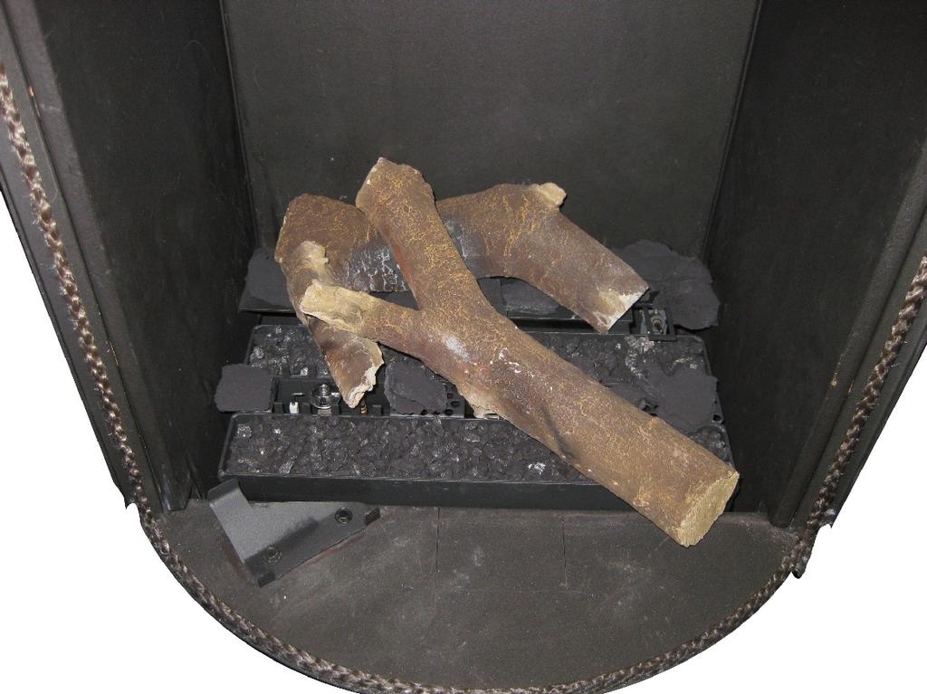
14 INSTLLTION MNUL Restrictor slide The restrictor slide (R) is supplied separately (see ppendix 3, Fig. 14). It is mounted as follows: Remove the glass pane as described in section ; Fully unscrew the 2 bolts of the top panel (see ppendix 3, Fig. 8 (P)); Remove the top panel (G); Unscrew the 2 self-tapping screws of the upper cover plate (see ppendix 3, Fig. 14 (J)); Remove the upper cover plate (J); Unscrew the 2 self-tapping screws from the combustion chamber; they are on the inside at the top of the appliance; Place the restrictor slide (R);!aution The restrictor slide may only be placed in one way. Therefore, observe the instructions in ppendix 3, Fig. 14. Tighten the 2 self-tapping screws by a few strokes, but not yet fully tight; Set the position of the restrictor in accordance with table 6; In the restrictor slide, the 3 possible positions are indicated by 3 cut out triangles. The letters at these triangles correspond with the letters in table 6. Make sure that the point of the triangle that belongs to the position required by you and the centre of the self-tapping screw are exactly aligned. Now tighten the 2 self-tapping screws; Place back the upper cover plate; Place back the top panel; Place back the glass pane as described in section Wood set The appliance is supplied with a wood set.!aution Strictly observe the following instructions to prevent unsafe situations: only ever use the supplied wood set place the wood set exactly as described make sure the pilot burner and the surrounding space remain free (see ppendix 3, fig. 15); make sure thermocouple 2 and the surrounding space remain free (see ppendix 3, fig. 16); make sure the slot between and around the burners remains free; make sure that the vermiculite s fine dust does not get on the burners Wood set The wood set consists of vermiculite (see ppendix 3, fig. 17), chips (see ppendix 3, fig. 18) and a number of logs. Glow material (see appendix 3, fig. 19) is not part of the appliance's standard equipment and is available at your dealer. Fill the burners with vermiculite; spread the vermiculite evenly (see ppendix 3, fig. 20). The vermiculite may not reach higher than the edge of the burners.!aution You can influence the flame picture by moving the vermiculite, yet the burner decks have to remain covered with vermiculite in order to prevent that the life span of the burners is reduced. Identify the logs to D (see ppendix 3, fig. 21).!Tip Use the burn stains on the logs for identification. Place log and part of the supplied chips at the back of the combustion chamber (see ppendix 3, fig. 22). Place log over the burner and on log (see ppendix 3, fig. 23). Place log in the position bracket and on log. Spread out the remaining chips (see ppendix 3, fig. 24).!aution Do NOT place chips over the slot around and between the burners. Then place log D in front of the burner on log and the chips (see ppendix 3, fig. 25).!aution The logs should not completely cover the burner pattern, because: the main burner will not ignite properly; which could result in unsafe situations; the appliance will become filthy more quickly, as a result of soot; the flame picture will be affected. 14
15 INSTLLTION MNUL 6. ontrol The appliance is supplied with a wireless remote control. ontrolling the flame height, igniting and switching off take place through a remote control controlling a receiver. hapter 4, Wireless remote control, in the User Manual describes the operation of the appliance and how you should use the remote control.!aution Do not ignite the appliance before the gas and discharge connections have been fully installed, first observe the procedure described in chapter 7.3; elow, we will describe how the receiver is connected. 6.1 onnecting the receiver Your appliance is equipped with an electronic ignition through the remote control. The receiver should be connected to the appliance, before the batteries are installed. onnect the receiver according to ppendix 3, fig. 38. end the antenna (N) out of the clips and place it erect (ppendix 3, fig. 39).!Tip The plugs have different sizes that correspond with the connectors. The size of the eye corresponds with the size of the screw; The colours of eye and screw correspond as well. Place the batteries as described below in section !aution Do not place the ignition cable over and/or along metal, stone or concrete parts: this will weaken the spark. Make sure the cable is hanging freely. Make sure that the wires of thermocouple 2 cannot come into contact with hot parts Keep the ignition cable at least 10 cm away from the antenna, in order to avoid damaging the receiver. void formation of dust on or in the receiver: cover it when performing work. Place the receiver in its intended holder under the appliance or in the control hatch according to ppendix 3, fig. 39. If you want to use an adapter, only an adapter supplied by DRU will guarantee a proper operation of the receiver Placing / replacing the receiver's batteries Follow the procedure below when placing the batteries: Pick up the receiver and slide off the cover. Place or remove the 4 penlite ( type) batteries.!aution Observe the "+" and "-" poles of the batteries and the receiver; Use alkaline batteries; rechargable batteries are not allowed. atteries are regarded as "small chemical waste" and may therefore not be disposed with the household rubbish. Slide back the cover. Place back the receiver. 6.2 Setting the communication code Prior to putting the application into operation, a communication code must be set between the remote control and the receiver. If the receiver or the remote control are replaced, a new code will have to be set. Follow the procedure described below: If necessary, place the batteries in the receiver's battery holder; see section If necessary, place the 9V block battery in the remote controle; see User Manual. Hold down the reset button on the receiver, until you hear two consecutive sound signals (see ppendix 3, fig. 40). fter the second, longer signal, let go of the reset button. Press the 'small flame' button on the remote control for 20 seconds, until you hear two short sound signals: this is the confirmation of a good communication. small flame large flame 15
16 INSTLLTION MNUL 6.3 lternative operation ppliances made with an electronic ignition and radio remote control can be connected to an alternative external control system (e.g. Domotics). For this purpose, there are 4 connection points at the side of the receiver (see ppendix 3, fig. 44). For connecting an external control unit, you will need a Domotics connection cable for GV60. onsult DRU's service website. The following contacts are possible: Ignition: connect both contacts 1 + 3, for one second (if there is a 2nd thermocouple, the appliance should burn at full power for at least 20 sec. before the required position can be chosen). Flame high(er): briefly close contact 1 once per step, or 12 seconds for the highest position. Flame low(er) until switch-off (pilot flame remains on): briefly close contact 3 once per step, or 12 seconds for the lowest position. ompletely switching off the appliance (pilot flame included): close all three contacts , for one second. The appliance will always continue to respond to the radio remote control supplied with it. The external control system is able to use one of the two modes of this remote control. 1. Manual mode This mode of the remote control is passive and will not take any action unless it is operated. The external control system is able to control the functions for high/low position, ignition and switching off.!tip If the external control system has an intelligent clock function and/or thermostat function, the remote control supplied with the appliance should have the manual mode in order to prevent interruption of these functions. 2. lock/thermostat mode This mode of the remote control is active and will be responsible for the clock function and thermostat function. The external control system is able to control the functions for high/low position, ignition and switching off.!tip If the appliance is switched off (the pilot flame included) manually or by one of the safeguards, ignition of the appliance will be blocked for a period of 3 minutes for reasons of safety. If it is no longer possible to operate the appliance with the external control system, you must switch it off and then switch it on again with the supplied remote control. 7. Final inspection In order to check whether the appliance is working properly and safely, you must perform the following inspections before the appliance is used. 7.1 Gastightness!aution ll connections must be gastight. heck the connections for gastightness. The gas control can be subjected to a maximum pressure of 50 mbar. 7.2 Gas pressure/line-pressure The burner pressure is set at the factory; see data plate.!aution The line-pressure in house installations must be checked, because it can be wrong. heck the line-pressure; see ppendix 3, fig. 41 for the measuring nipple on the gas control. ontact the gas company if the line-pressure is not correct. 16
17 INSTLLTION MNUL 7.3 Ignition pilot and main burner For igniting the pilot and main burner, see the User Manual, chapter 4, section 4.2, Remote control First ignition of the appliance after installation or adjustments!aution fter installation, or after work has been performed, you should ignite the appliance for the first time without the glass window. If necessary, bleed the gas pipe. Follow the procedure described below: If required, remove the glass window; Start the ignition procedure according to chapter 4 in the User Manual; If the pilot flame does not ignite: repeat the ignition procedure until the pilot burner ignites; consult the malfunction search diagram (ppendix 1) if this does not happen after a few attempts; fter igniting the pilot flame, the main burner will ignite during the ignition procedure; heck whether the main burner continues to burn; If the main burner does not continue to burn: repeat the ignition procedure until the main burner continues to burn consult the malfunction search diagram (ppendix 1) if this does not happen after a few attempts; Switch off the appliance; Then mount the glass window as described in chapter 5.10; Repeat the ignition procedure a few times and perform the checks described in chapter 7.3.2; From now on, the pilot flame should ignite smoothly.!tip When checking whether the main burner continues to burn, it is possible that it still switches off after 22 seconds. This happens because the appliance is equipped with a second thermocouple and the glass window has not been placed. In this case you may presume that the main burner will continue to burn.!aution During the ignition process, you are not allowed to operate control button on the gas control manually. lways wait 5 minutes after the pilot flame has gone out, before you re-ignite the appliance. You are not allowed to turn the pilot flame lower by using the settings on the gas control Main burner!aution The pilot burner should ignite the main burner within a couple of seconds, and without popping. The main burner(s) must cross the full burner smoothly and without popping and continue to burn. heck operation of the main burner from a cold condition (pilot flame off): fter opening the gas valve, the main burner should burn within a few seconds.!tip When the gas valve is opened, the motor will start to run; this is audible. The flame picture and a good flame transfer can only be properly judged if the glass window is installed. Use the malfunction search diagram (ppendix 1) if the ignition of the main burner does not comply with the abovementioned requirements. 7.4 Flame picture The flame picture can only really be assessed when the appliance has been burning for several hours. Volatile components from paint, materials, etc., which evaporate in the first hours, will affect the flame picture.!aution If the chimney breast has been made of stone-like materials or has a plaster finish, the appliance may only be put into operation 6 weeks after the chimney breast has been placed, in order to prevent shrinkage cracks. heck whether the flame picture is acceptable. onsult the malfunction search diagram (ppendix 1) if the flame picture is not acceptable. 17
18 INSTLLTION MNUL 8. Maintenance The appliance must be inspected once per year by a skilled installer in the field of gas-fired heating, and repaired if necessary. heck at least whether the appliance is working properly and safely.!aution lways close the gas tap during maintenance work; heck the gastightness after repair; fter replacing thermocouple 1 you should first tighten the gland nut by hand and then give it another quarter turn with a suitable spanner; You are not allowed to turn the pilot flame lower by using the settings on the gas control. If required, clean the following components: the pilot burner (malfunction search diagram, ppendix 1); the space surrounding the pilot burner; the glass pane(s).!aution Remove/place the glass pane(s) as described in section 5.10; Remove the deposit on the inside of the glass pane(s) with a damp cloth or a non-abrasive detergent such as copper polish or a ceramic hot plate cleaner; void/remove fingerprints on the glass pane(s), since otherwise they will burn into the surface; Replace a broken and/or cracked glass pane(s) as described in section 5.10.!aution If necessary, replace the wood or pebble set correctly; for this, see section Inspect the flue gas discharge system.!aution You must always perform a final inspection. Perform the inspection as described in chapter Parts Parts requiring replacement can be obtained from your supplier. 18
19 INSTLLTION MNUL 9. Delivery You must explain to the user how to operate the appliance. You must give him/her instructions on putting it in operation, the safety measures, the operation of the remote control and annual maintenance (see the User Manual).!aution Tell the user to close the gas tap immediately and contact the installer in case of malfunctions/poor operation. This to prevent unsafe situations; Indicate the location of the gas tap; Point out the precautions in the user manual against unintended ignition by other wireless remote controls such as car keys and garage door openers. Instruct the user about the appliance and the remote control. When the appliance is started for the first time, point out that In order to avoid cracks in a chimney breast made of stone-like materials or finished with plaster, it should dry for at least 6 weeks prior to putting the appliance into operation. When the appliance is stoked up for the first time, volatile components evaporate from paint, materials, etc. (First read chapter 3 of the User Manual as well!); When evaporating, the appliance should preferably be set to the highest level; The room should be well ventilated. Give the manuals to the user (all manuals should be stored near the appliance). 10. Malfunctions In ppendix 1 you will find an overview of malfunctions that might occur, the possible causes and the remedies. 19
20 INSTLLTION MNUL Start ppendix 1 diagnosis of malfunctions Fires with electronic ignition, fault finding: Ignition and burning 2.01 an pilot be lit? no yes 2.06 Pilot can be lit. Does it stay alight? yes 2.08 Does main burner ignite immediately? yes 2.10 Do(es) main burner(s) ignite smoothly and across its/their full length after first ignition by pilot burner? yes 2.02 Sparking? yes 2.03 Only one spark? no 2.04 heck: Receiver - Replace missing, weak or rechargeable batteries (not enough power to open thermoelectric valve). Presence of gas on pilot burner heck pilot on presence of gas at normal ignition cycle or in Manual Mode (turn oval knob on gas control to MN and keep safety shut off valve opened with a screwdriver) and ignite pilot with a lighter. - Pilot flame not on: Step 1. - Pilot flame on: Step 2. Step 1: Pilot has no gas heck: - Gas tap open? - Gas at gas control (line pressure at measuring point on gas control). - Gas flowing out of gas control? (by loosening pilot tube at gas control). If not: check adjustment screw pilot flame (under black cover): sealing not to be broken. Sealing broken: screw should be fully open. - locking of pilot tube (kink or dirt). - If this does not help: replace gas control. Step 2: Pilot has gas, but no ignition - Electrode with 90 bended tip: bend tip 1 mm higher. - Spark too weak (thin and reddish). ct as if 'no spark' in box 2.05 and perform actions described for ignition cable and ignition electrode. - Pilot flame too weak (dirty). Remove injector (remove gland nut and the pilot tube). See that it does not fall away. lean with compressed air. Rectify. Retry. no 2.03a - Loosen and retighten earthing screw on gas control. - If this does not work: replace receiver heck: Ignition cable - Present and connected. - eing free from metal parts or concrete. - Too long: cut away all excessive length at receiver end, and reconnect. - Shorting out to earth: replace ignition cable. - Spark in wrong position: - slide rubber sleeve on ignition cable over ceramic of electrode. - Replace electrode if neccessary. Ignition electrode - Straight electrode: - oxidation (roughen electrode with file or sand paper); - position (4 mm from pilot burner). - racks in ceramic (not always visible): replace electrode. Starting procedure fter switching off/going out the remote is locked for 120 sec. (older versions 60 sec). Wait 2 minutes before reigniting. no 2.07 Pilot out when servomotor starts to run? heck the thermocouple system. - Measure thermocouple voltage in mv just after servomotor starts to run and the voltage goes down. - Measure between red dot on receiver and earth point on gas control (fig. 42). - 0 mv mv mv - 6 mv and higher - Requirement: after rectification actions thermocouple voltage should be 6 mv at least, just after motor starts running! Voltage 0 mv - Thermocouple defective. heck by replacing or measuring voltage at end whilst heating (tip: with a lighter). - Short circuiting or interruptions in circuit: heck: - thermocouple tight in interruptor; - interruptor tight in gas control; - black wires (yellow/red end) connected to interruptor + receiver; - interruptor (mount thermocouple directly in gas control and ignite in Manual Mode (see 2.04). If pilot stays on: interruptor defective. Voltage 2-3 mv - heck pilot flame. Too small: - pilot dirty. lean up (see 2.04). - check for pilot gas tube tightness; - pilot tube kinks or dirt inside; - line pressure too low. - Tip: thermo couple not in (correct!) pilot flame. end into flame. Voltage 3-5 mv - ppliance may work, but is too critical. Perform actions as described for 2-3 mv. no 2.09 Ignition procedure - Oval knob on gas control is on "MN". Set to "ON" and restart. Retarded ignition of main burner(s) Gas to main burner opens ca. 3-5 seconds after servo motor, operating the gas valve, starts running (sound of motor!). fter this the main burner is to ignite (at least partially) within 10 seconds and not with a firm noise WHOOF. If not: no or delayed cross lighting of main burner. Hazardous situation. Stop ignition procedure straight away and first check for: - Position of logs or pebbles. - urner holes (locally) blocked. Remove vermiculite dust. - Vermiculite missing. - hips on burner. - Vermiculite not distributed evenly across burner(s). PowerVent (if present) urner does not light. onsult PowerVent installation manual how to carry out the checks below. heck: V to fan controller unit and fan. - Silicon pressure measurement hoses: - swapped; - leaking or barred. - Pressure difference set too high. - Resistance of flue system too high: - adjustment (of appliance damper and air inlet guides); - flue length or number of bends too large; - dirty (e.g. cobwebs). - Operation of the fan. - Operation of solenoid gas valve. - Operation of fan controller unit. - Operation of pressure measurement gauge. no 2.11 No proper cross lighting of main burner(s). Go to box 2.09 and take actions act as described for 'retarded ignition of main burner'. Voltage 6 mv and higher Voltage OK, so different cause. - Receiver defective. heck by dismounting black-red and yellow control cables from receiver and link together. Ignite fire in Manual Mode (see 2.04). Pilot stays on: receiver defective. - Gas control defective if receiver is not defective. Replace gas control. G 20
21 INSTLLTION MNUL 2.12 Does appliance switch off exactly 22 sec after servomotor starts running? no no yes yes 2.14 Does main burner go out 2.16 Is flame picture OK? 2.18 an fire be switched off? after 'some time'? 2.20 Perfect! You have a well functioning fire yes 2.13 heck cross lighting main burner and 2nd thermocouple system. Measure voltage of 2nd thermocouple - heck voltage in mv, 22 sec after servomotor starts to run, c.q. just before fire goes out. Glass window to be mounted! - Measure between black wire + earth point on gas control. - Requirement: voltage >5 mv after rectification actions. Voltage 0 mv - 2nd couple defective. - ross ligting main burner very slow. Take actions "ross lighting too slow" (see below), before taking any further action!! Voltage <1,8 mv - ross ligting main burner too slow. Take actions "ross lighting too slow" (see below), before taking any further action! - 2nd couple barred. heck: - 2nd couple free of vermiculite, chips or pebbles; - position of logs or pebbles; - burner holes under 2nd couple open. - 2nd couple defective (cross lighting OK, but voltage creeps up too slow). - Flames instable, see Rectify, before any other action is taken!! - urner pressure (too high or too low). - 2nd couple not positioned correctly in flame. end into correct position (see fig. 43). - 2nd thermocouple positioned correctly (see manual). end into flame (only if cross lighting and flame picture are OK!! See 2.17). Voltage > 1,8 mv - Receiver defective. Replace. ross lighting of main burner too slow Measure the time in sec from start running of servomotor till the flame reaches the 2nd couple. Requirement: the flame must be in position at the 2nd couple <10 sec. If not, check: - 2nd couple free from vermiculite, chips or pebbles; - position of logs or pebbles; - burner holes (locally) blocked. Remove vermiculite dust. - vermiculite missing or not evenly distributed across burner(s); - chips on burner; - lack of combustion air. See cross lighting in low setting (possible when thermostat function is used). yes 2.15 heck Gas supply - Supply pressure does not drop away as main burner (or other appliance) lights, causing pilot flame to shorten. - urner pressure (too high or too low). Flames instable (suffocating, lack of air). Dancing flames on burner. Lack of combustion air. heck: - flue system permissible; - proper flue terminal used, make should be 'DRU'; - terminal correctly sited on roof or wall relative to obstructions; - integrity of flueing system (no interruptions, not barred, cobwebs); - air inlet guides; - flue restrictor/damper; - throttle rings. See manual for specific requirements. PowerVent Possibly not enough draught. heck if pressure difference set too high. onsult PowerVent installation manual. Pilot burner - Pilot burner dirty. Weak pilot flame being drawn away by flames main burner. lean with compressed air. See no 2.17 heck Flames: too low - Supply pressure does not drop away as main burner or other appliances in the building light, causing flames to shorten. - urner pressure (too low). - False air: heck soundness glass window gasket/ soundness of the connection of the glass panes of two/three sided appliances (no slots allowed). Flames: too high - Line pressure. - urner pressure. Flames: no even distribution or out on part of the burner(s) - Position of logs or pebbles. - urner holes (locally) blocked. Remove vermiculite dust. - Vermiculite not distributed evenly across burner(s). - djustment of throttle ring(s). Flames: too blue/too yellow or sooting - ir inlet guides. - Flue restrictor/damper. - djustment of throttle ring(s). Flames: suffocating: lack of air You see dancing flames on burner, seeking for air. See Flame picture 'restless' Indication of too much draught. heck: - adjustment of appliance damper and air inlet guides); - vertical flue length allowed (<12 m); - window glass not mounted gas tight. PowerVent? heck: Possibly too much draught. heck: - Pressure difference set too high. - Silicon pressure measurement hoses leaking. onsult PowerVent installation manual for more info. no 2.19 Replace gas control (thermo-electric valve does not shut down quick enough because of some permanent magnetism). 21
22 INSTLLTION MNUL Malfunction search diagram atmospheric gas-fired heating appliance with electronic ignition: Starting up cycle. Start 1.01 Does receiver beep? no yes 1.03 One long 5 second beep, (possibly preceded by 7 short beeps). no 1.05 Short sound signals, 1 sec after each other, followed by the clicking noise of the gasvalve opening. yes yes no 1.02 Receiver - atteries missing or empty. Replace by 4x. fter replacing batteries: short beep. No beep: receiver defective. Replace by new one. - Replace rechargeables by alkaline batteries. - ommunication code between remote and receiver has to be (re)set: - Press reset button on receiver until brief beep, followed by long beep. - Release reset button and press 'flame low' button on remote within 20 seconds. Then 2 short beeps and brief noise of servomotor to confirm that communication code was set succesfully heck ll appliances - If there is an on/off switch, make sure it is set to 'on'. - 8 wire cable between receiver and gas control not connected, poor contact or one wire loose in connector (check by pulling wire by wire). - Wiring of thermocouple circuit interrupted, or poor contact. heck thermocouple, thermocouple interrupter and wiring. Sie box Microswitch on gascontrol defective. - The on/off switch is defective. heck by bridging the connection points swift beeps 1 sec after each other when motor turns or 3 brief short beeps within 1 sec at end of ignition cycle. yes 1.07 Replace batteries Measure battery voltage: <5.5V: replace preventative. <4.8V: appliance works no longer. Replace batteries. Turn two pages backwards and continue with box Remote control - attery 9V empty (see indication on display). Several - fter switching off/going out the remote set is locked for 120 sec. (older versions 60 sec). Wait 2 minutes before reigniting. ppliances with 2nd thermocouple only - 2nd thermocouple not cooled down sufficiently. Wait till cooled down (voltage < 0.8 mv), measure between black extension wire and earth). - Wiring of 2nd couple interrupted. heck black and red extension wire of 2nd couple to be connected to: - 2nd thermocouple (both wires); - receiver (black wire, can be forgotten at installing); - earth (red wire). - Else: receiver defective. Replace. 22
23 INSTLLTION MNUL ppendix 2 Tables Part Table 1: Parts included with the delivery Number Wood set 1x Installation manual User manual Decoration ring 1x 1x 1x Restrictor slide Hexagonal nut M5 Washer 8.4 mm Sealing cap Socket spanner 8 mm Remote control with receiver 9V block battery Penlite battery ( type) ompression fitting 15 mm x G3/8" 1x 2x 2x 2x 1x 1x 1x 4x 1x 23
24 INSTLLTION MNUL Product name Type of appliance ombustion Supply and discharge system Flame protection version 2nd thermocouple safety tmosphere safety Explosion hatch Type Gastype: Indirect heating functionality Direct heat output Indirect heat output Space heating emissions NO x Heat output Nominal heat output Minimum heat output (indicative) Technical data Nominal heat input (Hs) Nominal heat input (Hi) onsumption max onsumption min urner pressure max urner pressure min Main burner injector Low setting injector Efficiency class (EN613) Useful efficiency (NV)** Useful efficiency at nominal heat output Useful efficiency at minimum heat output (indicative) uxiliary electricity consumption t nominal heat output t nominal heat output In standby mode Permanent pilot flame power requirement Pilot flame power requirement (if applicable) Energy efficiency Energy efficiency index Energy efficiency class Table 2: Technical data Symbol P nom P min η th,nom η th,min el max el min el S P pilot G25/G25.3* No 6,0-91,4 6,0 2,7 8,2 7, ,2 5,0 1x Ø 1,55 1x Ø 1,70 Ø 1, ,3 89,0 EEI 92 Type of heat output / room temperature control Single stage heat output, no room temperature control Two or more manual stages, no room temperature control With mechanic thermostat room temperature control With electronic room temperature control With electronic room temperature control plus day timer With electronic room temperature control plus week timer Other control options Room temperature control, with presence detection Room temperature control, with open window detection With distance controle option * This appliance is suitable for G25.3 with the composition according NT ** System efficiency. *** To be used by means of home automation irco RE Free-standing losed combustion oncentric 150/100 Pilot flame with thermocouple yes no yes 11/31 G20 No 7,0-86,4 7,0 2,9 9,1 8, ,5 3,6 1x Ø x Ø 1.70 Ø ,5 87, G31 No 6,2-58,2 6,2 2,8 8,5 7, ,5 11,7 2x Ø 1.15 Ø ,9 89, Unit kw kw mg/kwh input (GV) kw kw kw kw L/h L/h mbar mbar mm mm % % kw kw kw kw No No No Yes Yes Yes*** Yes*** Yes*** Yes*** 24
25 INSTLLTION MNUL Table 3: Line-pressure when using G31 ountry NL / DK / FI / NO / SE / HU / / GR mbar 30 FR / E / IT / PT / ES / G / IE D Permissibility and conditions concentric system with wall terminal Table 4: onditions for setting the appliance G20/G25/G25.3/G31 Total number of meters vertical pipe length Total number of meters horizontal pipe length (excluding wall terminal) See Figure ir inlet guide Restrictor slide Distance of restriction in mm 1 1) ) 4 YES NO OPEN 1 1) NO NO OPEN 1) minimum length 2) factory setting 25
26 INSTLLTION MNUL Permissibility and conditions concentric system with roof terminal Table 5: Determining permissibility concentric system G20/G25/ G25.3/G31 Total number of meters horiz. pipe length Total no. of meters vertical and/or sloping pipe length no bends 2 bends D D D D D D 3 bends D 4 bends 5 bends = Situation is not permissible minimum length G20/G25/G25.3/G31 Table 6: onditions for the adjustment of the appliance with a roof terminal Situation ir inlet guide Restrictor slide Distance restrictor in mm NO NO OPEN YES YES 41 YES YES 34 D YES YES 25 26
27 INSTLLTION MNUL ppendix 3 Figures , ,5 372,5 1041, a 4a 38c-1777 /1 Min 40 mm 1x90 0 m Min 500 mm 1-4m q 2b 4b 45 1x90 0-3m Min 40 Min 222 Min 40 Min m / F 27
28 INSTLLTION MNUL 5 6 S 38c c-1779 D K 4x 7 38c-1780/1 Q T 28
29 INSTLLTION MNUL 8 G P 38c-1781/1 H 9 10 R 6x E 38c-1782 F 38c
30 INSTLLTION MNUL 11 = - = 38c G H L I 38c
31 INSTLLTION MNUL 13 L 38c c-1787 R J 31


32 IN ST L L T IO N M N U L P P p p P P


33 INSTLLTION MNUL 21 D 38P-0267/ P P


34 INSTLLTION MNUL 24 38P P-0271 D 34


35 IN S T LL T ION M N U L c p p ,7 15 SETION - SLE 1 : 20 38p /0 5mV 35
Circo G20/G25/G31. Installation manual (GB/IE) English. Store this document in a safe place DRU EN
 English. Store this document in a safe place DRU EN") irco G20/G25/G31 Installation manual (G/IE) Store this document in a safe place 959.044.01. DRU15798-175417-EN--0213-2 INSTLLTION MNUL ontents 1. Introduction 2. E declaration 3. SFETY 3.1 General 3.2
irco G20/G25/G31 Installation manual (G/IE) Store this document in a safe place 959.044.01. DRU15798-175417-EN--0213-2 INSTLLTION MNUL ontents 1. Introduction 2. E declaration 3. SFETY 3.1 General 3.2
Metro 130 XT Metro 130 XT Tunnel
 Metro 130 XT Metro 130 XT Tunnel G20/G25/G31 Installation manual (G/IE) Store this document in a safe place 959.041.00. DRU15798-112731-EN--0113-2 INSTLLTION MNUL ontents 1. Introduction 2. E declaration
Metro 130XT 41 RCH Metro 130XT Tunnel 41 RCH
 Metro 130XT 41 RH Metro 130XT Tunnel 41 RH G20/G25/G25.3 (Natural gas) G31 (Propane) Installation manual Store this document in a safe place 959.073.02.EN DRU-667777-EN-US-1017-3 EN ontents 1. Introduction
Maestro 80-2 RCH Maestro 80-3 RCH
 Maestro 80-2 RH Maestro 80-3 RH G20/G25/G25.3 (Natural gas) G31 (Propane) Installation manual (/IE) Store this document in a safe place 959.094.04. DRU-677279-EN-US-1016-5 INSTLLTION MNUL ontents 1. Introduction
Paco RCH. G20/G25/G25.3 Natural gas. Installation manual (UK/IE) English. Store this document in a safe place DRU EN-US
 English. Store this document in a safe place DRU EN-US") Paco RH G20/G25/G25.3 Natural gas Installation manual (/IE) Store this document in a safe place 959.098.01. DRU-680093-EN-US-0916-2 ontents 1. Introduction 2. E declaration 3. SFETY 3.1 General 3.2 Regulations
Paco RH G20/G25/G25.3 Natural gas Installation manual (/IE) Store this document in a safe place 959.098.01. DRU-680093-EN-US-0916-2 ontents 1. Introduction 2. E declaration 3. SFETY 3.1 General 3.2 Regulations
PowerVent. Installation manual (GB) English. Store this document in a safe place UK
 English. Store this document in a safe place UK") PowerVent Installation manual (GB) Store this document in a safe place 959.034.03.UK GB Contents Blz Foreword 3 1. Introduction 3 2. CE declaration 4 3. SAFETY 4 3.1 General 4 3.2 Regulations 4 3.3 Precautions
PowerVent Installation manual (GB) Store this document in a safe place 959.034.03.UK GB Contents Blz Foreword 3 1. Introduction 3 2. CE declaration 4 3. SAFETY 4 3.1 General 4 3.2 Regulations 4 3.3 Precautions
User manual (GB / IE) for appliances provided with an electronic ignition on the remote control. English. Read this document and store it carefully
 for appliances provided with an electronic ignition on the remote control. English. Read this document and store it carefully") User manual (GB / IE) for appliances provided with an electronic ignition on the remote control Read this document and store it carefully 958.007.07.uk 1 UK Contents page Preface 2 1. Introduction 3 2.
User manual (GB / IE) for appliances provided with an electronic ignition on the remote control Read this document and store it carefully 958.007.07.uk 1 UK Contents page Preface 2 1. Introduction 3 2.
PowerVent. Installation manual (GB) English. Store this document in a safe place UK
 English. Store this document in a safe place UK") PowerVent Installation manual (GB) Store this document in a safe place 959.078.00.UK GB Contents page Foreword 3 1. Introduction 3 2. CE declaration 4 3. SAFETY 4 3.1 General 4 3.2 Regulations 4 3.3 Precautions
PowerVent Installation manual (GB) Store this document in a safe place 959.078.00.UK GB Contents page Foreword 3 1. Introduction 3 2. CE declaration 4 3. SAFETY 4 3.1 General 4 3.2 Regulations 4 3.3 Precautions
PowerVent Installation manual. English. Store this document in a safe place EN
 PowerVent - 02 Installation manual Store this document in a safe place 959.114.01.EN en Contents Page Foreword 3 1. Introduction 3 2. CE declaration 4 3. SAFETY 4 3.1 General 4 3.2 Regulations 4 3.3 Precautions
Trio RCE. G20/G25/G25.3 (natural gas) Instructions for installation. English. Please retain this document carefully EN
 Instructions for installation. English. Please retain this document carefully EN") Trio RCE G20/G25/G25.3 (natural gas) Instructions for installation Please retain this document carefully 959.064.04.EN EN Contents page Preface 2 1. Introduction 3 2. CE Declaration 3 3. SAFETY 3 3.1 General
Trio RCE G20/G25/G25.3 (natural gas) Instructions for installation Please retain this document carefully 959.064.04.EN EN Contents page Preface 2 1. Introduction 3 2. CE Declaration 3 3. SAFETY 3 3.1 General
Duet XL /0929. Installation guide
 Duet XL 40010749/0929 ENG Installation guide ENG 1.1 1.2 1.3 1.4 1.5 A 1.6 1.7 1 < < < < B A 2.1 2.2 2.3 2.4 2 < < < < 2.5 2.6 2.7 2.8 3 < < < < 3.1 F F 3.2 3.3 4 < < < < Table of contents 1 Introduction...
Fyn Installation guide
 Fyn 450 400100929-1114 ENG Installation guide ENG 1.1 1.2 A B 1.3 1.4 1 < < < < 2.1 2.2 2.3 3.1 3.2 2 < < < < 4.1 4.2 4.3 4.4 3 < < < < Table of contents 1 Introduction... 6 2 Safety instructions... 6
Clear Installation guide
 Clear 40010631-0938 ENG Installation guide ENG 1.1 1.2 1.3 A 1.4 1.5 1 < < < < A B 2.1 2.2 2.3 C 2.4 2.5 2 < < < < 3.1 3.2 3-3 3 < < < < Inhoudsopgave 1 Introduction... 6 2 Safety instructions... 6 3 Installation
Solution Installation guide
 Solution 40011444-1327 ENG Installation guide ENG 1-1 1-2 1-3 1.4 1 < < < < 2.1 2-3 2-4 2 < < < < 3-1 3.2 3-3 3.5 3.6 3 < < < < 4-1 A 4-2 4-3 4 < < < < Dimensions Terminal position Distance (For good working
Fyn Installation guide
 Fyn 600 4001131-1123 ENG Installation guide ENG 1.1 1.2 A B 1.3 1.4 1 < < < < 2.1 2.2 2.3 2.4 3.1 3.2 2 < < < < 4.1 4.2 4.3 4.4 3 < < < < 1 Introduction The appliance can only be installed by a competent
Respect OC Installation manual
 Respect OC 40011335-1235 ENG Installation manual ENG 1.1 1.2 A 1.3 1.4 A A 2.1 2.2 2.3 1 < < < < 2.4 2.5 B C A B A 2.6 2 < < < < 3.1 3.2 3.3 3.4 3.5 3.6 3 < < < < A B 3.7 4 < < < < L A A 4.1 A A 4.2 A
Metro 70 - Metro 70 Tunnel
 Metro 70 - Metro 70 Tunnel G31 propane Instructions for installation (GB / IE) Please retain this document carefully UK Contents page Foreword 2 1. Introduction 3 2. EC Declaration of Conformity 3 3. SAFETY
VASKA B11. gas -fireplace installation guide
 VASKA B11 gas -fireplace installation guide Saturnus 8 NL-8448 CC Heerenveen Postbus 219 NL-8440 AE Heerenveen T. +31(0)513 656500 F. +31(0)513 656501 40 010 446 01 51 DESCRIPTION OF THE FIREPLACE CONTENTS
VASKA C11. gas-fireplace user manual. Saturnus 8 NL-8448 CC Heerenveen Postbus 219 NL-8440 AE Heerenveen T. +31(0) F.
 F.") VASKA C11 gas-fireplace user manual Saturnus 8 NL-8448 CC Heerenveen Postbus 219 NL-8440 AE Heerenveen T. +31(0)513 656500 F. +31(0)513 656501 40 010 458 01.51 DESCRIPTION OF THE FIREPLACE CONTENTS 1 2
VASKA C11 gas-fireplace user manual Saturnus 8 NL-8448 CC Heerenveen Postbus 219 NL-8440 AE Heerenveen T. +31(0)513 656500 F. +31(0)513 656501 40 010 458 01.51 DESCRIPTION OF THE FIREPLACE CONTENTS 1 2
Relaxed Premium M Relaxed Premium M ENG
 Relaxed Premium M 40010959 1440 Relaxed Premium M ENG 3 alternative finishes. 1.1a 1.1b 1.1c 1 < < < < 1.2 1.3 7 1.4 2 < < < < 1.5 1.6 B 1.9 3 < < < < 2.1 2.2 2.3 3.1 3.2 3.3 3.4 4 < < < < 3.5 4.1 4.2
VASKA C11. gas -fireplace installation guide
 VASKA C11 gas -fireplace installation guide Saturnus 8 NL-8448 CC Heerenveen Postbus 219 NL-8440 AE Heerenveen T. +31(0)513 656500 F. +31(0)513 656501 40 010 459 01 51 DESCRIPTION OF THE FIREPLACE CONTENTS
Duet Premium M Duet Premium M ENG
 Duet Premium M 40011422-1441 Duet Premium M ENG 1.1 1.2 1.3 1.4 1.5 1.6 1.7 1.8 1 < < < < 2.1 a 2.1 b 2.1 c A C 2.2 2 < < < < F F 2.3 X H X C 2.4 2.5 S T 3.1 3.2 R Q 3.3 3 < < < < 4.1 4.2 4.3 4.4 4 <
Vaska Logburner. voorbeeld Installation guide
 Vaska ogburner voorbeeld 40010627-2103 ENG Installation guide ENG 1.1 1.2 1.3 1.4 1.5 1 < < < < 1 Introduction The appliance can only be installed by a competent person in accordance with the Gas Safety.
Installation Manual EF5000 AUS & NZ
 Installation Manual EF5000 AUS & NZ This manual is ONLY for fires with a serial No. from 80600 to 80999. Important: The appliance shall be installed in accordance with; Local gas fitting regulations Municipal
Operating Instructions Wine storage refrigerator 12/
 Operating Instructions Wine storage refrigerator 12/98 7080641 1 The wine storage refrigerator you have purchased differs from normal refrigerators in that it is suitable for long-term storage of wine.
Duet Premium L Duet Premium L ENG
 Duet Premium L 40011297-1441 Duet Premium L ENG 1.1 1.2 1.3 1.4 1.5 1.6 1.7 1.8 1 < < < < 2.1 a 2.1 b 2.1 c A C 2.2 2 < < < < F F 2.3 X H X C 2.4 2.5 S T 3.1 3.2 R Q 3.3 3 < < < < 4.1 4.2 4.3 4.4 4 <
Kalahari DECORATIVE FUEL EFFECT GAS FIRE
 Kalahari DECORATIVE FUEL EFFECT GAS FIRE User Instructions These instructions should be read by the user before operating the appliance and retained for future reference Model No. KRDC00MN & KRDC00SN are
CRYSTAL FIRES. Inset Conventional Flue Fire. (BOSTON/MIAMI) Cf1 and MANHATTAN USER INSTALLATION AND SERVICING INSTRUCTIONS
 Cf1 and MANHATTAN USER INSTALLATION AND SERVICING INSTRUCTIONS") CRYSTAL FIRES (BOSTON/MIAMI) Cf1 and MANHATTAN Inset Conventional Flue Fire USER INSTALLATION AND SERVICING INSTRUCTIONS FOR USE WITH NATURAL GAS G20 @ 20 mbar For use in GB and IE CE THESE INSTRUCTIONS
CRYSTAL FIRES (BOSTON/MIAMI) Cf1 and MANHATTAN Inset Conventional Flue Fire USER INSTALLATION AND SERVICING INSTRUCTIONS FOR USE WITH NATURAL GAS G20 @ 20 mbar For use in GB and IE CE THESE INSTRUCTIONS
Installation Manual EF5000 NZ
 Installation Manual EF5000 NZ Important: The appliance shall be installed in accordance with; Local gas fitting regulations Municipal building codes AS/NZS 5601.1.1:2010 Gas Installation Any other relevant
ELECTRIC FLAT PANEL FIREPLACE HEATER
 ELECTRIC FLAT PANEL FIREPLACE HEATER Model Numbers: 80-2000A-42 OWNER S MANUAL AC 120V 60Hz 1500W WARNING Read and understand this entire owner s manual, including all safety information, before plugging
72 ONYX XL FLAT PANEL ELECTRIC FIREPLACE
 72 ONYX XL FLAT PANEL ELECTRIC FIREPLACE Model Numbers: 80005 OWNER S MANUAL WARNING Read and understand this entire owner s manual, including all safety information, before plugging in or using this product.
GLOBAL 40 CF FITTING INTO A CONVENTIONAL CLASS 1 CHIMNEY
 INSTALLATION INSTRUCTIONS GB/IE GLOBAL 40 CF FITTING INTO A CONVENTIONAL CLASS 1 CHIMNEY DRU VERWARMING B.V. HOLLAND 957.669.00 CONTENTS Site: 3 Important 3 Foreword 4 Instructions for installation 4 Ventilation
FIREPLACE INSTALLATION
 CHECK GAS TYPE Use proper gas type for the fireplace unit you are installing. If you have conflicting gas types, do not install fireplace. See retailer where you purchased the fireplace for proper fireplace
Installation and Operation Manual For Hunter Ceiling Fans
 Installation and Operation Manual For Hunter Ceiling Fans 1 2 CONGRATULATIONS! Your new Hunter ceiling fan is an addition to your home or office that will provide comfort and performance for many years.
50 FLAT PANEL BUILD IN ELECTRIC FIREPLACE
 50 FLAT PANEL BUILD IN ELETRI FIREPLAE Model Numbers: 1703 OWNER S MANUAL WARNING Read and understand this entire owner s manual, including all safety information, before plugging in or using this product.
Hestia Installation Guide
 Hestia 40010610-0746 UK Installation Guide Content 1.1 1.2 1.3 1.4 A B C D 1.5 1.6 1 < < < < Hestia with Wirdum Surround 2.1 2.2 2.3 2.4 2.5 2.6 > > > > 2 Hestia with Jellum Surround 3.1 3.2 3.3 3.4 3.5
900 Quadrant Steam Shower Cabin with 6 Body Jets
 Product Specification Working Pressure 1.5 to 4 bar Pressure MUST be balanced Dimensions 2250 H x 900 D x 900 W Door Opening 480mm Steam Generator 2.8Kw Fuse size: 13 amp fuse spur 900 Quadrant Steam Shower
60cm Chimney Extractor
 60cm Chimney Extractor LAM2401 HJA2480 User & Installation Guide Contents Page Environmental note 3 IMPORTANT SAFETY INFORMATION 4 6 Specifications of your extractor 7 8 Dimensions 7 Specifications 7-8
Stainless Steel and Glass Angled Extractor
 Stainless Steel and Glass Angled Extractor HJA2600 User & Installation Guide CONTENTS Environmental Note 3 Product information 4 4 Parts List 4 Method of Extraction 5 Installation 6 Hanging Your Extractor
Instructions for use. Gas hobs for installation in worktops GKS GWS GKS GKS
 Instructions for use Gas hobs for installation in worktops GKS 3920.0 GWS 3911.0 GKS 6940.0 GKS 9951.0 For use in: Hong Kong Issue: 2014-01-14 Version: 1.3_EN Identity no.: 073587_HK Welcome 2 Welcome
Installation and maintenance instructions
 6304 4994 03/2006 GB For installer Installation and maintenance instructions Flue gas heat exchanger WT30/40 Please read thoroughly prior to installation and maintenance. Contents Contents Contents 2 1
Installation and maintenance instructions
 6304 4995 0/004 GB For installer Installation and maintenance instructions Flue gas heat exchanger WT50/60 Please read thoroughly prior to installation and maintenance. Summary About this manual This equipment
HOW TO USE YOUR 2500 RANGE L.P.G. COOKER OR HOB UNIT
 HOW TO USE YOUR 2500 RANGE L.P.G. COOKER OR HOB UNIT CAUTION These instructions must be read and understood before proceeding with the installation and to avoid any possibility of accident it is essential
Wall Mount Electric Fireplace
 Wall Mount Electric Fireplace User Guide Thank you for purchasing the Ivation Wall Mount Electric Fireplace. This User Guide is intended to provide you with guidelines to ensure that operation of this
BT16.4SS-HK BT19.4SS-HK Cooker Hood
 BT16.4SS-HK BT19.4SS-HK Cooker Hood User Manual for your Baumatic User Manual for your Baumatic BT16.4SS-HK 60 cm Chimney Hood BT19.4SS-HK 90 cm Chimney Hood NOTE: This User Instruction Manual contains
WAILEA OWNER S MANUAL
 WAILEA OWNER S MANUAL The blades in each pack are matched for equal weight to assure smooth fan operation. If more than one fan is being installed, be careful not to mix blades from different cartons.
NO VENTING REQUIRED 120V AC;
 ELECTRIC FIREPLACE Model Number: Alice (EF172B-EF176B) OWNER S MANUAL WARNING Read and understand this entire owner s manual, including all safety information, before plugging in or using this product.
CANOPY RANGEHOOD ONBOARD INSTALLATION INSTRUCTIONS
 Congratulations on your purchase! Thank you for choosing a Sirius product. CANOPY RANGEHOOD ONBOARD INSTALLATION INSTRUCTIONS SLTC 97 900 EAN# 9351116001612 SL22 900 EAN# 9351116000660 SL7 1200 EAN# 9351116000813
BWTC6510GL Cooker Hood 60 cm Glass cooker hood in stainless steel. BWTC9510GL Cooker Hood 90 cm Glass cooker hood in stainless steel
 User Manual for your BWTC6510GL Cooker Hood 60 cm Glass cooker hood in stainless steel BWTC9510GL Cooker Hood 90 cm Glass cooker hood in stainless steel NOTE: This User Instruction Manual contains important
Servicing manual. Wall-mounted condensing gas boiler 600 Series - 11S / 19S / 24S / 24C /2002 GB(EN) For trade use
 For trade use") GB122 7210 1300-12/2002 GB(EN) For trade use Servicing manual Wall-mounted condensing gas boiler 600 Series - 11S / 19S / 24S / 24C Please read thoroughly before attempting to diagnose fault List of contents
GB122 7210 1300-12/2002 GB(EN) For trade use Servicing manual Wall-mounted condensing gas boiler 600 Series - 11S / 19S / 24S / 24C Please read thoroughly before attempting to diagnose fault List of contents
SAFIRE 1600D, 1800D and 2100D Diesel / fuel oil heaters USAGE, INSTALLATION AND MAINTENANCE
 SAFIRE 1600D, 1800D and 2100D Diesel / fuel oil heaters 1 Heater kit contains : Heater, mounting bracket Fuel hose (3 meters), pump, a fuel tank connection to standard tanks (15, 22, 30 litres) Power supply
Servicing manual. 600 Series - 11S / 19S / 24S / 24C. Wall-mounted condensing gas boiler. For trade use
 GB122 Servicing manual Wall-mounted condensing gas boiler 600 Series - 11S / 19S / 24S / 24C For trade use Please read thoroughly before attemting to diagnose fault 7217 4900 (03/2010) GB/IE List of contents
24 VAC SYSTEM CONTROL KIT
 24 VAC SYSTEM CONTROL KIT Model: CK-91F and CK-91FG Designed for use with the SWG Series Power Venter for controlling Natural Gas or L.P. Gas draft induced appliances with a 24 VAC Gas Valve and a 30-millivolt
Kalahari RC & Camber RC
 Kalahari RC & Camber RC DECORATIVE FUEL EFFECT GAS FIRE User Instructions These instructions should be read by the user before operating the appliance and retained for future reference Model No s KRDC**RN
Proline GAS HOB Model TCG40IX Instruction Book
 Proline GAS HOB Model TCG40IX Instruction Book GB Operating and Installation Instructions Index Technical data and specifications...... 3 Installation...................... 3-6 Ventilation........................
Fully-automatic Gas tankless Water Heater USER'S MANUAL FOR MODEL EZ-101 ISO9001 certified
 Fully-automatic Gas tankless Water Heater USER'S MANUAL FOR MODEL EZ-101 ISO9001 certified Thank you for purchasing our fully-automatic gas-fired tankless water heater. Please completely read this Manual
Eccotemp L5 and L10 Comprehensive Troubleshooting Guide
 http://waterheatertimer.org/tent-city-usa-water-heater.html Eccotemp L5 and L10 Comprehensive Listed below are some common questions and troubleshooting guidelines for our various models. Always remember
Gas Instantaneous Water Heater
 6 720 607 823 GB (06.06) SM Installation and Operating Instructions Gas Instantaneous Water Heater WR10..B... WR11..B... With electronic ignition and triple safety system consisting of ionisation detector,
CEILING FAN OWNER S MANUAL
 Style that revolves around you. CEILING FAN OWNER S MANUAL Total fan weight *53 lbs. WEXFORD 11/05 WARNING: Read and follow these instructions carefully and be mindful of all warnings shown throughout.
ValkyrieTM. Instruction Manual. Includes our new CoolTouch TM 6 Speed DC Control System Looks permanent, but goes wherever you go! U.S.
 ValkyrieTM A Kichler Décor ceiling fan Designed to coordinate with a popular Kichler Lighting collection. Includes our new CoolTouch TM 6 Speed DC Control System Looks permanent, but goes wherever you
Torch framed Installation Guide
 Torch framed 40010567-0602 Installation Guide 1 2 3 4 1 < < < < 5 6 7 > > > > 2 Content 1 Introduction... 1 2 Safety Instructions... 2 3 Installation requirements... 3 3.1 Rear surface construction...
(manual control) (ezi-slide control) INSET COAL EFFECT GAS CONVECTOR FIRE V1/100/B INSTALLATION & USER INSTRUCTIONS
 (ezi-slide control) INSET COAL EFFECT GAS CONVECTOR FIRE V1/100/B INSTALLATION & USER INSTRUCTIONS") Model Number: V1/100/A V1/100/B (manual control) (ezi-slide control) INSET COAL EFFECT GAS CONVECTOR FIRE INSTALLATION & USER INSTRUCTIONS GB IE SUITABLE FOR USE ON NATURAL GAS (G20) AT 20mbar SUPPLY PRESSURE
Model Number: V1/100/A V1/100/B (manual control) (ezi-slide control) INSET COAL EFFECT GAS CONVECTOR FIRE INSTALLATION & USER INSTRUCTIONS GB IE SUITABLE FOR USE ON NATURAL GAS (G20) AT 20mbar SUPPLY PRESSURE
OWNER S MANUAL. FLAT PANEL FIREPLACE HEATER Model Number: Serena (EF202A) WARNING CAUTION
 WARNING CAUTION") FLAT PANEL FIREPLACE HEATER Model Number: Serena (EF202A) OWNER S MANUAL WARNING Read and understand this entire owner s manual, including all safety information, before plugging in or using this product.
FLAT PANEL FIREPLACE HEATER Model Number: Serena (EF202A) OWNER S MANUAL WARNING Read and understand this entire owner s manual, including all safety information, before plugging in or using this product.
Stainless Steel Chimney Extractor
 Stainless Steel Chimney Extractor User & Installation Guide LAM2404 LAMONA Appliances Dear Customer, Congratulations on your choice of a LAMONA domestic appliance which has been designed to give you excellent
16 Ultiflame Inset Electric Fire
 16 Ultiflame Inset Electric Fire B-1001645 Packing Checklist Electric Fire Remote Control Handset 2 x AAA Batteries Log Set Ember Ice Set Instruction Manual Fascia IMPORTANT PLEASE READ THESE INSTRUCTIONS
INSTALLATION INSTRUCTIONS GB/IE
 INSTALLATION INSTRUCTIONS GB/IE Global 55 CF Global 55XT CF Fitting into a Conventional Class 1 Chimney DRU VERWARMING B.V. HOLLAND 957.771.00 CONTENTS Site: 3 Important 3 Foreword 4 Instructions for installation
Cooker Hood Instruction Manual
 Cooker Hood Instruction Manual Model number(s): RHSCH601SS/B & RHSCH901SS/B IMPORTANT: RETAIN FOR FUTURE REFERENCE Contents Safety Instructions. 3-6 Product Overview. 7 Positioning. 8 Operational modes.
Installation Instructions & Operating Manual IMPORTANT
 Installation Instructions & Operating Manual IMPORTANT These instructions should be read carefully and retained for future reference TABLE OF CONTENTS SECTION 1: WARNINGS & ELECTRIC SPECIFICATIONS 1.1
INSTALLATION MANUAL. Split-type Air Conditioner (Cooling and Heating) Outdoor Unit UQB09JJWC UQB12JJWC. Indoor Unit AQB09JJWC AQB12JJWC
 Outdoor Unit UQB09JJWC UQB12JJWC. Indoor Unit AQB09JJWC AQB12JJWC") AQB09JJ6WC_IM_E_2585 2006.4.17 4:26 PM Page 17 INSTALLATION MANUAL Indoor Unit AQB09JJWC AQB12JJWC Outdoor Unit UQB09JJWC UQB12JJWC ENGLISH FRANÇAIS ESPAÑOL Split-type Air Conditioner (Cooling and Heating)
AQB09JJ6WC_IM_E_2585 2006.4.17 4:26 PM Page 17 INSTALLATION MANUAL Indoor Unit AQB09JJWC AQB12JJWC Outdoor Unit UQB09JJWC UQB12JJWC ENGLISH FRANÇAIS ESPAÑOL Split-type Air Conditioner (Cooling and Heating)
USER MANUAL. 80 cm 2 burners, glass hob AKC 820C/BLM
 USER MANUAL 80 cm 2 burners, glass hob AKC 820C/BLM For your safety These instructions have been drawn up for your safety and that of others. You are therefore requested to read them carefully before installing
gas Understanding Gas Appliance Conversions READ ALL INSTRUCTIONS
 SUNSTONE DOUBLE SIDE BURNER LIQUID PROPANE TO NATURAL GAS CONVERSION INSTRUCTION PAGE 1 OF 8 Understanding Gas Appliance Conversions Making changes to an appliance so that it can utilize a different fuel
INSTALLATION AND USER S MANUAL COOKER HOOD RS-600/A-S
 INSTALLATION AND USER S MANUAL COOKER HOOD RS-600/A-S RS-600 (CHS60SS)-GB-05.indd 1 6/8/2010 9:30:59 AM TABLE OF CONTENTS 1. Introduction 2 2. Safety precaution 2 3. Intended use 3 4. Parts supplied 3
IMPORTANT SAFETY INSTRUCTIONS DANGER: WARNING:
 IMPORTANT SAFETY INSTRUCTIONS YOUR SAFETY AND THAT OF OTHERS IS PARAMOUNT This manual and the appliance itself provide important safety warnings, to be read and observed at all times. This is the attention
FLAME HEATER PYRAMID CLFH-10SS OPERATION INSTRUCTIONS
 FLAME HEATER PYRAMID CLFH-10SS OPERATION INSTRUCTIONS www.colorato.net For outdoors use only Uses propane, butane or LPG only Reflector: 47x47 mm Total Height: 2250 mm Regulator s external pressure: 28-30
Installation and service must be provided by a qualified installer, service agency or the gas supplier.
 INSTALLATION AND OPERATION GUIDE FOR OLDE WORLD BASKET Vented Decorative Appliance For all models tested through PFS Corporation, to ANSI Z21.60-2003/CGA 2.26-2003, Decorative Appliance for Installation
Built-in Gas Hob CZ55554 CZ55571
 Built-in Gas Hob CZ55554 CZ55571 INSTALLATION AND OPERATING INSTRUCTIONS The product may differ from the one illustrated but the installation and operation procedure remains the same The product may differ
INSTALLATION & USERS INSTRUCTIONS. FOR USE WITH NATURAL GAS 20 mbar For use in GB and IE
 1 valentine s buildings Bechers drive Aintree racecourse Business Park L9 5ay CF1 L GAS APPLIANCE INSET CONVENTIONAL FLUED GAS FIRE INSTALLATION & USERS INSTRUCTIONS FOR USE WITH NATURAL GAS G20 @ 20 mbar
Heat Exchanger Block Replacement Instructions
 Series 1-4 Gas-fired water boiler Heat Exchanger Block Replacement Instructions Ultra-80 S1-4 Heat Exchanger Block Replacement Kit, Part No. 383-500-773 Ultra-105 S1-4 Heat Exchanger Block Replacement
Stainless Steel Chimney Extractor
 Stainless Steel Chimney Extractor HJA2450-2 User & Installation Guide LAMONA Appliances Dear Customer, Congratulations on your choice of a LAMONA domestic appliance which has been designed to give you
HG 675 CX 60 HG 675 CN 60 HG 675 CW 60
 HG 675 X 60 HG 675 CX 60 HG 675 CN 60 HG 675 CW 60 1 2 1. : 93/68: 90/396: 2006/95/CE: 2004/108/CE: - 1935/2004:. 2002/95/CE: RoHS 2.,.,,,,...,. (,..)..,,.,. ( ),,, ;,,.,.....,.,,,,,,...,. (..),,.,..,.,,,,
This document was created with FrameMaker 4.0.4
 This document was created with FrameMaker.0. WELCOME TO TODAY S GENERATION OF COMFORT Congratulations! Your new, higher efficiency gas furnace is a sound investment which will reward you and your family
INSTALLATION AM
 INSTLLTION M 000.. SFETY INSTRUCTIONS This Manual must be read before installing the irmaster air handling unit. Following this Manual will ensure this product is operated correctly. The manufacturer cannot
USER MANUAL. 60cm, 3 burners, Hob AKC 630
 USER MANUAL 60cm, 3 burners, Hob AKC 630 For your safety These instructions have been drawn up for your safety and that of others. You are therefore requested to read them carefully before installing
π H-2268 SANITAIRE UPRIGHT VACUUM SAFETY uline.com
 π H-2268 SANITAIRE UPRIGHT VACUUM 1-800-295-5510 uline.com SAFETY PAGE 1 OF 7 NOTE: When using an electrical appliance, basic precautions should always be followed, including the following: READ ALL INSTRUCTIONS
HORIZONTAL COOKING SERIES: 700 / 900 S.A.V MAINTENANCE & AFTER SALES WORK PPS-3WE711911CH
 SERIES: 700 / 900 S.A.V MAINTENANCE & AFTER SALES WORK PPS-3WE711911CH GENERAL Tools Every time you se this symbol it is vital that you have the tool indicated to ensure correct and compliant work is undertaken
Contents. 1. Instructions for safe and proper use Positioning of hob Attachment to support structure Electrical connection 22
 Contents 1. Instructions for safe and proper use 19 2. Positioning of hob 20 2.1 Attachment to support structure 20 3. Electrical connection 22 4. Gas connection 23 4.1 Connection to LPG 24 4.2 Ventilation
INSTRUCTIONS MANUAL FOR USE AND MAINTENANCE
 INSTRUCTIONS MANUAL FOR USE AND MAINTENANCE Carbel models: C-60 Plus C-70 Plus C-80 Plus C-100 Plus C-70 Plus Double-sided C-80 Plus Double-sided C-100 Plus Double-sided CARBEL C/ Ciudad de Cartagena,
Conversion Instructions Logano G234X. Gas boiler. Please read carefully before installing and servicing. Gas boiler
 Gas boiler UPON COMPLETION OF THE INSTALLATION THE INSTALLER MUST INSTRUCT THE OWNER AND OPERATOR ON THE FUNCTIONALITY AND THE PROPER OPERATION OF THE BOILER AND THE HEATING SYSTEM. INSTALLER MUST REVIEW
INSTALLATION INSTRUCTIONS
 Proper Disposal of Your Old Refrigerator WRNING Suffocation Hazard Remove doors from your old refrigerator. Failure to do so can result in death or brain damage. IMPORTNT: hild entrapment and suffocation
BWT6.3GL Cooker Hood 60 cm Glass chimney hood
 User Manual for your BWT6.3GL Cooker Hood 60 cm Glass chimney hood NOTE: This User Instruction Manual contains important information, including safety & installation points, which will enable you to get
Atmos EasySolar. Installation Instructions for. In-roof and flat roof installation with flat plate collectors
 Atmos EasySolar Installation Instructions for Atmos EasySolar In-roof and flat roof installation with flat plate collectors Atmos Heating Systems West March Daventry Northants, NN11 4SA Tel: 01327 871990
21 20 LITER GAS FRYER FFA3200 INSTALLATION AND SERVICING.
 21 20 LITER GAS FRYER FFA3200 INSTALLATION AND SERVICING www.anvilworld.com 20 ALL ANVIL EQUIPMENT COMES WITH A ONE YEAR WARRANTY ON COMPONENTS AND DEFECTIVE WORKMANSHIP. www.anvilworld.com 19 20 LITER
52 CEILING FAN READ AND SAVE THESE INSTRUCTIONS FAN RATING AC 120V.
 Irene 52 CEILING FAN READ AND SAVE THESE INSTRUCTIONS FAN RATING AC 120V. 60Hz TABLE OF CONTENTS Tools and Materials Required... 1 Package Contents... 1 Safety Rules... 2 Mounting Options... 3 Hanging
R 18 E MANUEL D'UTILISATION GEBRAUCHSANWEISUNG INSTRUCCIONES DE USO OPERATING MANUAL ISTRUZIONI D USO GEBRUIKSAANWIJZING
 R 18 E 3 2 5 > 1 MANUEL D'UTILISATION GEBRAUCHSANWEISUNG INSTRUCCIONES DE USO OPERATING MANUAL ISTRUZIONI D USO GEBRUIKSAANWIJZING 2 1 26 38 50 62 Dear Sir, Madam, Congratulations on your purchase of this
ELTSHDC110SG/ Users Guide & Installation Instructions
 ELTSHDC110SG/ Users Guide & Installation Instructions CONTENTS IMPORTANT SAFETY INFORMATION Installation Page 2 Child Safety 2 Maintenance and service 3 YOUR APPLIANCE OPERATING INSTRUCTIONS Cooker Hood
SIERRA RADIANT HEAT MAJESTIC OAK VENTED GAS LOG KIT INSTALLATION AND OPERATING INSTRUCTIONS
 SIERRA RADIANT HEAT MAJESTIC OAK VENTED GAS LOG KIT INSTALLATION AND OPERATING INSTRUCTIONS WARNING: If the information in this manual is not followed exactly, a fire or explosion may result causing property
Revision B Printed Fall Elston Manufacturing HC Heater Owners Manual
 Revision B Printed Fall 2007 Elston Manufacturing HC Heater Owners Manual Table of Contents Important Safety Information... ii 1) Description of Heater... 1 General information about your heater including
Contents. For your safety About your product Installing your appliance Using your appliance Care & cleaning...
 USER GUIDE TF5517S Contents For your safety..................................................... 1 About your product.................................................. 3 Installing your appliance...............................................
Install Guide Customer Support: or Visit our website
 Install Guide 8095 ustomer Support: 888-515-2585 or Visit our website www.ritetemp.biz Install Guide 8095 aution Tools 1 Location To avoid electrical shock and to prevent damage to the furnace, air conditioner,
Operating instructions
 Operating instructions Gas condensing boiler WARNING: If the information in this manual is not followed exactly, a fire or explosion may result causing property damage, personal injury or loss of life.