VIEW BELL SMALL 3 CF/LF
|
|
|
- Sybil Black
- 5 years ago
- Views:
Transcription
1 INSTALLATION INSTRUCTIONS & MANUAL FOR MAINTENANCE VIEW BELL SMALL 3 CF/LF Gas fi res with closed combustion system Bellfi res wishes you many cosy evenings with your new Bellfi res gas fi re This document is an essential part of your gas fi re. Read it carefully before installation and maintenance of the gas fi re and keep it in a safe place! Serial number: Production date:
2
3 BELLFIRES GAS FIRE WITH CLOSED COMBUSTION SYSTEM: View Bell Small 3 CF (Centre Fire) View Bell Small 3 LF (Line Fire) (VWBS3 CF) (VWBS3 LF) 3
4 4
5 CONTENTS Page 1. INSTALLATION INSTRUCTIONS MAINTENANCE FAULTS DISMANTLING / ASSEMBLING OF THE GLASS DIAGRAM ELECTRICITY AND GAS DIMENSIONS TECHNICAL DETAILS/REGULATIONS REPLACEMENT PARTS LIST DISPOSAL OF PACKAGING AND APPLIANCE IMPORTANT The installation must only be carried out by a Gas Safe Register registered installation engineer. 5
6 6
7 1 INSTALLATION INSTRUCTIONS 1.1 GENERAL The gas fi re must be positioned and connected as a room sealed system (balance fl ue) appliance by a Gas Safe Register registered gas installation engineer in accordance with the following installation instructions, nationally and locally applicable regulations (see Technical Details/ Regulations at the rear of this manual). If you have any queries regarding the installation, please consult your local gas company. Important: Before beginning the installation, check that the details on the rating plate correspond to the gas type and pressure to which the appliance will be connected. The appliance is supplied with a Centre Fire or Line Fire double burner, as ordered. These burners each have their own specifi c fl ame image which is defi ned by the perforation pattern in the burner cover. See Chapter 5 and the Instructions for use. The appliance is factory set to the correct nominal heat input. The pilot light is set to the correct level of consumption. Depending on the requested version, the appliance will be delivered from the factory with a Ø100 mm - Ø150 mm or Ø130 mm - Ø200 mm concentric connection for extracting the fl ue gases and supply of combustion air. It is possible to install the gas fi re with either a wall or roof outlet. The roof connection must be carried out using the concentric fl ue system Ø100 mm - Ø150 mm. The fumes are exhausted naturally to the outside environment through the inner Ø100 mm pipe whereas the combustion air supply passes between the Ø100 mm and Ø150 mm pipes. The wall connection must be carried out using the concentric fl ue system Ø130 mm - Ø200 mm. The fl ue gases are evacuated outside by means of natural draft through the internal pipe of Ø130 mm, whereas the combustion air is supplied between the pipes of Ø130 mm and Ø200 mm. The wall outlet itself is, depending on the concentric fl ue gas system confi guration, Ø100 mm - Ø150 mm or Ø130 mm - Ø200 mm. (In some cases, with a wall connection, a complete concentric fl ue system Ø100 mm - Ø150 mm is also possible (see Chapter 1.6.1).) The gas fi re can be installed in a completely sealed or mechanically ventilated house without extra ventilation and/or fume extraction. The gas fi re can be installed as an insertion into an existing open fi re place or as a built-in appliance in a new fi re place. In order to prevent the fireplace heating up excessively, it must be properly ventilated by installing vents at the top and bottom of the fi replace. 7
8 The appliance can be fi tted with a convection package as an optional extra. This is a convection jacket (convection casing) for around and above the appliance, two fl exible aluminium pipes and two built-in convection vents. This enables hot air to be circulated into the room. If required, two additional convector grills can be fi tted (= 1x extra convection set). If an existing chimney is to be used, please consult your installer fi rst. If the chimney was previously used for a wood or coal fi re, then it should be cleaned by an expert. 1.2 CONCENTRIC FLUE SYSTEMS Ø100 MM - Ø150 MM AND Ø130 MM - Ø200 MM : Bellfires (Muelink & Grol system) Poujoulat (PGI system) Ontop (Metaloterm US system) The gas fi re, in combination with the concentric fl ue system [Ø100 mm - Ø150 mm] and/ or [Ø130 mm - Ø200 mm] (rigid and/or fl exible) for the brands Bellfi res (Muelink & Grol system), Poujoulat (PGI system) or Ontop (Metaloterm US system), has been approved in accordance with the European CE-norm for gas appliances and may therefore be used only with these systems. The permitted components for these systems are listed in Chapter The guarantee on the appliance lapses if it is installed, fully or partially, with other components or a different fl ue system. The concentric fl ue [Ø100 mm - Ø150 mm] and [Ø130 mm - Ø200 mm] systems can be used with either a newly-built or existing chimney. 1.3 INCLUDED Set documentation - Instructions for use - Attributes - Ceramic log set, or marble pebbles white or marble pebbles grey N.B. If any part is missing, please contact your dealer. 8
9 1.4 OPTIONS AND ACCESSORIES The following options and accessories can be supplied by your dealer: Part no Option Convection package View Bell Small x Convection casing x Convection top plate x Convection set General Mantle iron VWBS cm Frame 4 sided VWBS3 (incl. mantle iron VWBS3) Black mirror rear wall CBS3 L/R / VWBS (3x) Fins rear wall CBS3 L/R / VWBS3 Part no Accessorie Convection set General: (for convection air extraction) x Flexible aluminium pipe Ø125 mm, L= 3 m (max.) x Fitting box 135 x 135 mm x Convection exit grid, white, 145 x 145 mm x Collar adaptor Ø125 mm x Hose clamp Ø125 mm Set carrying brackets (2 pieces) 3... Bellfi res (M&G) concentric fl ue system See component summary 3... Poujoulat (PGI) concentric fl ue system See component summary 3... Ontop (Metaloterm US) concentric fl ue system See component summary 9
10 1.5 PREPARATION FOR INSTALLATION The following preparation must be carried out before the gas fi re can be installed Instructions for positioning the outlet Positioning the outlet for correct operation: Roof-mounted outlet: >0.5 m Figure 1: Roof-mounted outlet This must be positioned at least 0.5 m from the roof edge; the apex of the roof can be disregarded. Wall-mounted outlet: >0.5 m Figure 2: Wall-mounted outlet This must be positioned at least 0.5 m from: the corner of the building. the roof overhang, the rain gutter. balconies etc., unless the exhaust construction extends to at least the face of the protruding section. 10
11 Positioning the outlet to avoid affecting the surrounding area All listed distances in this section are no more than guidelines. For the exact minimum distances, please consult your national and local directives. Distance = minimum distance required for positioning of the outlet to avoid adverse effects with respect to: A. A ventilation opening serving an occupied room, a toilet or a bathroom. B. A heating air supply, when the supply fl ows through an occupied room. C. A window that can be opened and that is near an occupied room, a toilet or a bathroom. Roof-mounted outlet: To avoid adverse effects Distance: outlet - A, B or C At the same roof level. >3 m (*) At a different roof level. >1 m (*) At a lower positioned wall. >1 m At a higher sloping surface. >3 m (**) (*) If the required distance cannot be achieved, the outlet position rules take precedence. (**) If the required distance cannot be achieved, the position of the outlet must be at least 1 m above the highest facade/roof. 11
12 Wall-mounted outlet: To avoid adverse effects At walls in buildings with staggered heights. Distance: outlet - A, B or C Not permitted if A, B, or C are located above the outlet. On a wall - general. (*) Above the outlet: >2 m Below the outlet: >0.75 m Left and right of the outlet: >0.75 m At <1 m from the roof overhang. Beneath balconies, walkways etc. Beneath balconies, walkways etc. where the outlet extends to the front. >2 m >2 m from the underside of the protruding balcony or walkway. >2 m To the garden or on the terrace. >2 m to the outside space. (**) With respect to a facing wall. >2 m (if the distance from the facing wall is less, the criteria detailed for On a wall - general apply). Enquire at your local gas company for the regulations relating to outlets positioned opposite each other and outlet(s) in facade(s) that form an angle. (*) These minimum distances do not apply if there is an obstruction between the outlet and A, B and C that protrudes at least 0.5 m from the wall and has a length exceeding the distance. (**) This distance is not required if the outlet is situated at least 1 m higher than the intended area of the outside space. If the outlet has a clearance of less than 0.5 m from the hard surface of a public area at a height of less than 2 m, it must be fi tted with an effective protector. The mesh size of the guard must not affect the correct operation of the appliance. 12
13 1.6 GENERAL SERVICES The Fume Channel/Combustion Air Intake The combined fume channel and combustion air intake requires one of the following concentric fl ue system confi gurations. Important: Due to the high temperature of the outer walls (approx. 150 C), no flammable materials may be located or used in the vicinity of the flue system. The complete flue system, must therefore be sleeved with a heat resistant material after assembly. Ventilate the covered concentric flue by fitting a grid near the floor and ceiling (on each floor). Do not insulate the concentric flue. Use the universal wall/floor support Ø150 mm to attach the covering of the concentric flue system [Ø100 mm - Ø150 mm], see 1.6.2, drawing number Use as a wall support Use as a fl oor support Figure 3: Application universal wall/floor support Ø150 mm 13
14 RIGID CONCENTRIC FLUE Ø100 mm - Ø150 mm SYSTEM CONNECTION POSSIBILITIES Appliance: Concentric flue connection Ø100-Ø150 mm or Ø130-Ø200 mm Y , 11, 12, 13 (100) Item descriptions: see Assemble restriction plate: Appliance: Distance Y Concentric Concentric (min.-max.) connection connection on appliance is on appliance is Ø100-Ø150 mm Ø130-Ø200 mm View Bell Small m m Width: B = 30 mm Width: B = 40 mm Width: B = 65 mm Width: B = 80 mm Figure 4: Vertical roof-mounted outlet without bend ALL SIZES INCLUDE THE LENGTH OF THE ROOF OR WALL TERMINATION 14
15 16 17 Y X , 15 10, 11, 12, 13 Y 1 28 (100) 4 1 Item descriptions: see Assemble restriction plate: Appliance: Distance Y 1 (*) Distance X (*) Distance Y 1 + Y 2 (*) Concentric Concentric (min.-max.) (min.-max.) (min.-max.) connection connection on appliance is on appliance is Ø100-Ø150 mm Ø130-Ø200 mm View Bell Small m m m - Width: B = 40 mm (*) : (Y 1 + Y 2 ) : X > 2 : 1 (Vertical to horizontal ratio (or 45 upwards) is always at least 2 to 1) Figure 5: Vertical roof-mounted outlet with bend ALL SIZES INCLUDE THE LENGTH OF THE ROOF OR WALL TERMINATION 15
16 FLEXIBLE CONCENTRIC FLUE Ø100 mm - Ø150 mm SYSTEM CONNECTION POSSIBILITIES Appliance: Concentric flue connection Ø100-Ø150 mm or Ø130-Ø200 mm Y , 11, 12, (100) 4 Item descriptions: see Assemble restriction plate: Appliance: Distance Y Concentric Concentric (min.-max.) connection connection on appliance is on appliance is Ø100-Ø150 mm Ø130-Ø200 mm View Bell Small m m Width: B = 30 mm Width: B = 40 mm Width: B = 65 mm Width: B = 80 mm Figure 6: Vertical chimney outlet using an existing lined chimney (Flexible Ø100 mm and/or rigid Ø100 mm / Ø150 mm) ALL SIZES INCLUDE THE LENGTH OF THE ROOF OR WALL TERMINATION 16
17 Y Y 2 > 45 X 5 7 Y 1 10, 11, 12, (100) 1 Item descriptions: see Assemble restriction plate: Appliance: Distance Y 1 (*) Distance X (*) Distance Y 1 + Y 2 + Y 3 (*) Concentric Concentric (min.-max.) (min.-max.) (min.-max.) connection connection on appliance is on appliance is Ø100-Ø150 mm Ø130-Ø200 mm View Bell Small m m m - Width: B = 40 mm (*) : (Y 1 + Y 2 + Y 3 ) : X > 2 : 1 (Vertical to horizontal ratio (or 45 upwards) is always at least 2 to 1) Figure 7: Vertical chimney outlet using a lined chimney with a bend > 45 (Flexible Ø100 mm and/or rigid Ø100 mm / Ø150 mm) ALL SIZES INCLUDE THE LENGTH OF THE ROOF OR WALL TERMINATION 17
18 Y (100) 1 Item descriptions: see Assemble restriction plate: Appliance: Distance Y Concentric Concentric (min.-max.) connection connection on appliance is on appliance is Ø100-Ø150 mm Ø130-Ø200 mm View Bell Small m m Width: B = 30 mm Width: B = 40 mm Width: B = 65 mm Width: B = 80 mm Figure 8: Vertical chimney outlet using an existing unsound lined chimney or when no chimney liners are present (Flexible Ø100 mm / Ø150 mm) ALL SIZES INCLUDE THE LENGTH OF THE ROOF OR WALL TERMINATION 18
19 Y Y 2 > X 7 Y (100) 1 Item descriptions: see Assemble restriction plate: Appliance: Distance Y 1 (*) Distance X (*) Distance Y 1 + Y 2 + Y 3 (*) Concentric Concentric (min.-max.) (min.-max.) (min.-max.) connection connection on appliance is on appliance is Ø100-Ø150 mm Ø130-Ø200 mm View Bell Small m m m - Width: B = 40 mm (*) : (Y 1 + Y 2 + Y 3 ) : X > 2 : 1 (Vertical to horizontal ratio (or 45 upwards) is always at least 2 to 1) Figure 9: Vertical chimney outlet using an existing unsound lined chimney or when the chimney is unlined; with a bend >45 o (Flexible Ø100 mm / Ø150 mm) ALL SIZES INCLUDE THE LENGTH OF THE ROOF OR WALL TERMINATION 19
20 RIGID CONCENTRIC FLUE Ø100 mm - Ø150 mm SYSTEM CONNECTION POSSIBILITIES and with wall outlet Ø100 mm - Ø150 mm Appliance: Concentric flue connection Ø100-Ø150 mm or Ø130-Ø200 mm X m Y 10, 11, 13 Wall Termination Position 28 (100) 4 1 Item descriptions: see Assemble restriction plate: Appliance: Distance Y Distance X Concentric Concentric (min.-max.) (min.-max.) connection on connection on appliance is appliance is Ø100-Ø150 mm Ø130-Ø200 mm View Bell Small m m m m - - Figure 10: Horizontal wall termination ALL SIZES INCLUDE THE LENGTH OF THE ROOF OR WALL TERMINATION 20
21 RIGID CONCENTRIC FLUE Ø130 mm - Ø200 mm SYSTEM CONNECTION POSSIBILITIES and with wall outlet Ø100 mm - Ø150 mm Appliance: Concentric flue connection Ø130-Ø200 mm X m Y 110, 111, 113 Wall Termination Position Item descriptions: see Assemble restriction plate: Appliance: Distance Y Distance X Concentric connection on (min.-max.) (min.-max.) appliance is Ø130-Ø200 mm View Bell Small m m Width: B = 40 mm m m - Figure 11: Horizontal wall termination ALL SIZES INCLUDE THE LENGTH OF THE ROOF OR WALL TERMINATION 21
22 RIGID CONCENTRIC FLUE Ø130 mm - Ø200 mm SYSTEM CONNECTION POSSIBILITIES and with wall outlet Ø100 mm - Ø150 mm Appliance: Concentric flue connection Ø130-Ø200 mm 114 X m Y , 111, 113 Wall Termination Position Item descriptions: see Assemble restriction plate: Appliance: Distance Y Distance X Concentric connection on (min.-max.) (min.-max.) appliance is Ø130-Ø200 mm View Bell Small m m m m - Figure 12: Horizontal wall termination ALL SIZES INCLUDE THE LENGTH OF THE ROOF OR WALL TERMINATION 22
23 RIGID CONCENTRIC FLUE Ø130 mm - Ø200 mm SYSTEM CONNECTION POSSIBILITIES and with wall outlet Ø100 mm - Ø150 mm Appliance: Concentric flue connection Ø130-Ø200 mm X m 110, Y , 111, 113 Wall Termination Position 114 X 1 Y 1 110, 111, Item descriptions: see Assemble restriction plate: Appliance: Distance Y 1 Distance X 1 Distance Y 2 Distance X 2 Concentric connection on (min.-max.) (min.-max.) (min.-max.) (min.-max.) appliance is Ø130-Ø200 mm m m m m - View Bell Small m m m m m m m m m m m m - Figure 13: Horizontal wall termination ALL SIZES INCLUDE THE LENGTH OF THE ROOF OR WALL TERMINATION 23
24 RIGID CONCENTRIC FLUE Ø130 mm - Ø200 mm SYSTEM CONNECTION POSSIBILITIES and with wall outlet Ø130 mm - Ø200 mm Appliance: Concentric flue connection Ø130-Ø200 mm 114 X m Y , 111, 113 Wall Termination Position Item descriptions: see Assemble restriction plate: Appliance: Distance Y Distance X Concentric connection on (min.-max.) (min.-max.) appliance is Ø130-Ø200 mm View Bell Small m m m m - Figure 14: Horizontal wall termination ALL SIZES INCLUDE THE LENGTH OF THE ROOF OR WALL TERMINATION 24


25 1.6.3 Gas connection Operation (gas regulator block (and receiver)) outside the appliance (in the operating unit): The gas connection is situated where the operating unit is built in near to the appliance. Use only gas piping with a minimum diameter of 1/2 and a shut-off valve Operating unit If the appliance is fi tted with an operating unit comprising gas control block and receiver, this will be located, once it has been built in, at a maximum of 50 cm from the left or right hand side of the appliance Convection package connections When fi tting a convection package (= convection casing and convection set (1x or 2x)), consideration should be given to the openings at approximately 1 meter above the appliance for the warm air exiting grids. 1.7 POSITIONING THE APPLIANCE Important: The fireplace is constructed on a sufficiently solid floor that can bear the weight of the appliance. Ensure a free space of at least 1 cm between the bottom of the appliance and the floor. Ensure that the temperature of the floor under and in front of the appliance can never rise above 85 C! Make use of a temperature protection plate (of nonflammable material) on the floor if necessary. Take care with a floor made of a flammable material. Min.1 cm Figure 15: A clearence of at least 1 cm must be maintained between the bottom of the appliance and the floor. 47
 The rear wall must be made of nonflammable material. Never use combustible materials during the installation.")
26 Never position the appliance directly against the rear wall, but always place an nonflammable insulation plate, at least 12 mm thick, between the appliance and the rear wall, with free space on either side of 2 cm. (Total ± 5 cm.) The rear wall must be made of nonflammable material. Never use combustible materials during the installation. Ventilate the fireplace, by allowing vents above and below the fireplace. During installation of the gas fire, a clearance of 3 mm should be maintained on all sides of the appliance to allow for expansion of the appliance during operation. Do not insulate the appliance! Only the top and sides may be fitted with a strip of white, loose insulation wool (heat-resistant to 1000 C), width 15 cm max. to protect the wall. Do not use fibreglass or Rockwool, or any other sort of insulating material. These emit a pungent odour. This is considered extremely unpleasant. They may also cause discolouring of the column. Flammable materials, such as curtains, should not be placed in the vicinity of the gas fire. Minimum safe distance: 100 cm. If desired, fi t a convection package to the appliance. (See chapter 1.1) The appliance can be easily installed using a set of carrying brackets (accessory). After installing: remove carrying brackets! View Bell Small 3 with options: 10 cm frame (4 sided) and mantle iron convection package 48
 1x extra convection set 1 Inlet opening (appliance) convection air 2 Inlet opening (grate)")
27 Figure 16: Appliance installed in ventilated chimney breast Horizontal outlet of the flue gas exhaust /combustion air supply via the wall. Fitted with the options / accessories: convection package (= convection casing and 1x convection set) 1x extra convection set 1 Inlet opening (appliance) convection air 2 Inlet opening (grate) (chimney breast) convection air 3 Natural convection in the chimney breast 4 Outlet opening (grate) (chimney breast) natural convection air 5 Outlet opening (appliance) convection air / connection convection set (2x or 4x) 6 Outlet opening (grill convection set) (chimney breast) convection air (2x or 4x) 7-8 Concentric fl ue connection appliance; Ø mm for a horizontal wall outlet 9 Horizontal wall outlet 10 Built in operating unit with gas regulator block and receiver 49
28 Figure 17: Appliance installed in ventilated chimney breast Vertical outlet of the flue gas exhaust / combustion air supply via the roof. Fitted without convection package 1 Inlet opening (appliance) convection air 2 Inlet opening (grate) (chimney breast) convection air 3 Natural convection in the chimney breast 4 Outlet opening (grate) (chimney breast) convection air (2x) 5 Concentric fl ue connection appliance; Ø mm for a vertical roof outlet 6 Concentric fl ue system; Ø mm for a vertical roof outlet 7 Built in operating unit with gas regulator block and receiver 50
, after removing the")

, the appliance can be adjusted to the required height.")

29 When fi tting the appliance, it can be levelled with the adjustable feet. These adjustable feet can be reached via the openings (4x), after removing the protective covers, in the corners of the fl oor of the combustion chamber. The fl oor of the combustion chamber can be reached after the window and the grill around the burner have been removed (see chapter 4). Using an Allenkey (no. 5), the appliance can be adjusted to the required height. Press the 4 protecting covers back into the fl oor Position 4 protecting covers. - Protecting cover. - Adjustable feet seen from the bottom - Adjust height with Allenkey no. 5. of the appliance. 51
30 Position the gas supply pipe such that it can be easily mounted after installation. Because the control system is outside the appliance, the gas pipe must lead to where the operating unit (built in), the gas regulator block (and the receiver) assembly are fi tted. Move the appliance until it is ± 5 cm from the rear wall and ensure it is level. Place the nonfl ammable insulation plate (min. 12 mm) between the appliance and rear wall. The appliance may not be installed against a fl ammable rear wall. Attach the appliance to the rear wall with 2 wedge bolts. Use the adjustable mounting brackets at the side of the appliance for this. - 2x Mounting bracket. 52
31 1.7.1 Gas connection operating unit Important: During gas connection, take care not to twist the gas regulator block. Make sure that both the gas regulator block and the supply pipes are not subjected to stresses. The appliance is supplied with a built-in operating unit. Operating unit Frame with door (white) Figure 18: Operating unit Remove the decorative edging and door of the operating unit. Fit the separate operating unit, where the gas regulator block and receiver will be placed, on max. 50 cm from the appliance. The burner, gas regulator block and receiver have been fully factory assembled. Disconnect the bracket with the gas regulator block and receiver from the appliance. Carefully move the bracket with the gas regulator block, receiver, pipes and cables to the operating unit. Mount the bracket at the bottom of the operating unit. Important: Take care that no pipes get damaged and no compression fittings come loose when moving the gas regulator block. Prevent twisting the flexible pipes! Check all compression fittings for leaks afterwards! Mount the receiver in the top of the operating unit. Check afterwards that all electric connections are properly connected. General: Route all piping and cables from the operating unit to the appliance through an easily accessible hollow cavity. During subsequent installation of the operating unit, protect the gas regulator block and piping against encasement by cement etc. 53

32 Important : Cement and chalk can damage the piping and can, in turn, lead to gas leaks. Disassembly and assembly of pipes and cables: If necessary for mounting, all pipe compression fi ttings and cable connectors can be temporarily disassembled. After mounting, carefully reassemble all pipes and cables. Check afterwards all compression fi ttings for leaks and that all electric connections are properly connected. Important : Note : Screw the thermocouple connection (and thermocouple interrupter) manually into the gas regulator block. Afterwards, carefully fasten a half turn with a spanner. Check that the flexible burner pipes are correctly connected! The gas connection of the gas valve rear burner must be connected to the rear burner! See Chapter 5. Switching over the flexible burner pipes during assembly can lead to an explosive ignition. Prevent this at all costs! Gas pipe rear burner Ø8 mm Flex. Thermocouple Pilot light pipe Ø4 mm Flex. Gas valve rear burner Thermocouple interrupter Gas pipe front burner Ø8 mm Flex. Gas supply connection Gas regulator block Figure 19: Gas regulator block and gas valve: Gas and thermocouple connections 54


33 Pilot Gas Adjustment Screw (Pierce the housing with a small screwdriver) Adjustment Screw Maximum Burner pressure Motor-knob 8 Wire connecting cable receiver Microswitch Figure 20: Gas regulator block - Front Inlet Pressure Tap Outlet Pressure Tap Adjustment Screw Minimum Burner pressure Pilot light connection Gas supply connection Thermocouple interrupter connection Gas connection for to the front burner Gas connection for gas valve to the rear burner Figure 21: Gas regulator block - Rear 55
 TC AUX: Electrical connection for gas valve rear burner Connection 8 wire cable gas regulator")

34 Piezo cable connection Thermocouple voltage / current OUT - connection (yellow) SW Thermocouple voltage / current IN - connection (red) TC AUX: Electrical connection for gas valve rear burner Connection 8 wire cable gas regulator block Connection for external operating (option) 6 VDC Adapter connection (option) RESET button Figure 22: Receiver - Top RESET button AUX: Electrical connection for gas valve rear burner Figure 23: Receiver - AUX connection - RESET button 56

 The convection package (option) consists")


35 1.7.2 Connecting the concentric flue Assemble the concentric fl ue system according to one of the examples in section 1.6.1, fi gure 4 to 14 inclusive. Make sure that all connections are completely gas tight Mounting the convection package (option) The convection package (option) consists of a convection casing and a convection set. The convection set is supplied separately and consists of two fl exible aluminium pipes, hose clamps and two built-in convection grills (fi tting box and grill). Mount the aluminium pipes on the collar adaptors of the convection top plate. Use the supplied hose clamps. The fl exible aluminium pipes are stretchable to a length of + 3 meter. 57


36 Position the two fi tting boxes in the fi replace, at a minimum distance of 30 cm under the ceiling. Mount the other end of the aluminium pipes onto the fi tting boxes. To do this use the hose clamps supplied. When the fi replace is completely fi nished, mount the grilles onto the fi tting boxes. Within a range of 30 cm either side and 50 cm above the escape opening, there must be no fl ammable materials (e.g. wooden ceiling, fi tted furniture) Building in the appliance Remove the front of the casing, if applicable. (See Chapter 4: Dismantling / Assembling of the glass.) Decide on positions of the vents (grilles above and below the fi replace) and, if applicable, the hot air grids of the convection package. The brickwork must be built up around the appliance. In connection with the appliance expanding during burning: there must be at least 3 mm clearance on either side of the appliance. Do not build up the brickwork farther than the angle irons/brackets (keep in mind the thickness of any plastering!). Do not use masking tape on the appliance when installing and plastering. Tape can damage the finish of the appliance. Connect up the convection package, if applicable. See


37 Mantle iron (option). The optional mantle iron is intended for supporting the brickwork above the appliance. The mantle iron must rest on the brickwork on both sides so that upward building is possible. Level the mantle iron with the supplied bar set. Mantle iron in combination with the 10 cm frame (option). The mantle iron is screwed on the top panel of the 4 sided 10 cm frame at the factory. Do not unscrew this connection! Bar set: 2x draw bars 2x tension sleeves 2x M6 hooks 2x brass expansion plugs M6 First remove the 2 mantle iron transport-spacers REMOVE Note! Temporarily support the mantle iron, so that it does not fall forwards. 59
.")


38 Fix the mantle iron to the rear wall with the bar set. Place the draw bars at an angle of about 60 (between the appliance and the wall). Level the mantle iron with the tension sleeves. 2 mm Ensure that the height between the mantle iron and the underside of the glass is the same at left, middle and right. Keep a clearance of 2 mm between the mantle iron and the top of the side panels. The side panels should always be easily removable. Check that the mantle iron is at right angles to the side panels, both left and right. Put ceramic felt on the top of the mantle iron, before laying bricks or using other heatresistant structural materials. If using other materials, such as stone or heat-resistant plating, you should follow the supplier s instructions. 60

39 DO NOT COVER Do not cover the top side of the appliance with (built-in) materials. Once the fi replace has been fi nished, you can now, fi t the frame with the small door to the operating unit. After installation in a new fireplace and/or applying new cement work, the appliance cannot be used for at least four weeks. 61
40 1.7.4 Checking the gas connection After connection of the gas supply, check that all connections are completely gas tight using soapy water or a leak tester Positioning the ceramic log set or marble pebbles The appliance can be supplied with: Ceramic log set + embers Marble pebbles white (small, white marble stones) Marble pebbles grey (small, grey marble stones) Important: Carefully place the chips of wood/embers/vermiculite granules/ log set or marble pebbles, on and around the main burner according to the directions in this chapter. Do not place any chips of wood/embers/vermiculite granules/ log set or marble pebbles against the pilot light burner. For that reason, the main burner has a protective pilot-light cowl. Never remove this cowl! Make sure that the pilot flame can burn at all times freely over the main burner. Only in this way is proper ignition of the main burner ensured. Ignoring these directions could lead to a dangerous situation. Make sure that all burner orifices remains free at all times! The burner bed (with chips of wood/embers/vermiculite granules) and the positioning of the logs or marble pebbles must not be changed. Only use those items supplied! These been rigorously checked and the quantities adapted to the appliance. Replacement parts, including the ceramic mat are available from your dealer. Fitting may only be carried out by a qualified person. Remove the glass according to the instructions in chapter 4; DISMANTLING / ASSEMBLING OF THE GLASS. 62


41 Ceramic log set + chips of wood + embers + vermiculite granules 1 Place the ceramic mat on the burner in such a way that the holes in the mat are in line with the burner openings. 2 Remove the embers carefully from their packaging and spread them evenly over the burner mat and the grate around the burner. 3 Distribute the vermiculite granules (50 gram) evenly over the burner. 63
42 Note! : Small embers and their residue should not be scattered on the burner. This can cause a blockage on the burner orifices. Embers and vermiculite granules must not be placed next to the pilot light burner. Important: make sure that all burner openings remain free!! Burner orifices, which are not open, could lead to a dangerous situation. 4 Place the logs on the burner: Appliance Natural gas-burner see fi gure: Propane / Butane-burner see fi gure: View Bell Small 3 CF/LF Keep the burner orifi ces unblocked!!! 5 Place the chips of wood around the burner. 64


43 Logs: Log no ❶ Log no ❷ Log no Log no ❹ Log no ❺ Log no ❻ Log no ❼ Log no ❽ 65


44 ❼ ❷ ❹ ❶ ❻ Keep the burner orifi ces unblocked! Embers must not be placed next to the pilot light burner Figure 24: Log set View Bell Small 3 CF/LF Position natural gas burner ❼ ❷ ❶ ❹ ❻ Embers must not be placed next to the pilot light burner Keep the burner orifi ces unblocked! Figure 25: Log set View Bell Small 3 CF/LF Position propane/butane burner 66
45 Marble pebbles 1 Place the ceramic mat on the burner in such a way that the holes in the mat are in line with the burner openings. 2 Spread the pebbles over the whole burner bed (burner and grid around the burner). Make sure that the pilot light remains free. View Bell Small 3 CF/LF : see fi gure 27 Keep the burner orifi ces unblocked IMPORTANT: Open area, in order to ensure free accessibility of the pilot fl ame to the burner Figure 26: Marble pebbles-set natural gas and propane/butane-burner 67


46 Keep the burner orifi ces unblocked! Marble pebbles must not be placed next to the pilot light burner Keep the burner orifi ces unblocked! Figure 27: Marble pebbles View Bell Small 3 CF/LF Position natural gas and propane/butane burner Important: Do not place any marble pebbles in front of the pilot light. Make sure that the pilot light can burn freely over the main burner. Keep the burner orifices unblocked. Only this way a proper ignition of the main burner is ensured. Once the logs / marble pebbles have been positioned, replace the glass in the appliance, following the instructions in chapter 4: DISMANTLING / ASSEMBLING OF THE GLASS Mounting flue gas restriction plate Depending on the length and shape of the concentric fl ue system and the chimney construction, you should, if indicated, fi t a restriction plate with a certain width (B) into the ceiling of the combustion chamber. To do this, see the set-up options as listed in fi gure 4 through

47 Important: Ensure that the correct flue gas restriction plate is mounted. Use of the correct flue gas restriction plate will provide optimum efficiency, flame effect and combustion. Mounting an incorrect flue gas restriction plate can result in damage to the gas fire. Screw fastening (2x) Assembly restriction plate Figure 28: Positioning restriction plate 69
48 The following restriction plates are supplied: Concentric fl ue connection appliance [Ø mm] [Ø mm] Restriction plate: Horizontal wall outlet Roof-mounted outlet Width: - B = 30 mm Width: B = 40 mm B = 40 mm Width: B = 50 mm B = 50 mm Width: B = 65 mm B = 65 mm Width: B = 80 mm Check overpressure hatches There are two overpressure hatches in the roof of the combustion chamber (front). Check that the hatches are loose, by lifting a little and carefully letting them come down again. Check if the packing under the hatches is sealed. 70


49 Left overpressure hatch is in the correct position. Right overpressure hatch is in the correct position. Check functioning of overpressure hatch. Check packing of overpressure hatch. If necessary, the packing can be replaced by lifting the hatch, tilting it and removing via the opening Checking the appliance following installation After installation, visually check the gas fl ame. When the fi re is ignited, the fl ames should be short and blue/yellow in colour. These fl ames should gradually increase in height and become more yellow. When all fl ames are yellow, the gas fi re has reached the correct temperature. THE GAS FIRE IS NOW READY FOR USE 71
50 2 MAINTENANCE 2.1 ANNUAL MAINTENANCE It is essential that the appliance, the complete concentric flue system (where possible) and the outlet are cleaned and inspected annually by a recognised fitter/gas specialist. The safe operation of the appliance will thus remain guaranteed. Maintenance consists of the following: Remove fi rst the embers, vermiculite granules, logs set or pebbles from the main burner and carefully clean these with a soft brush. Clean and inspect (visually) the main burner, pilot light, combustion chamber, fl ue system and combustion air intake. Dust can be removed using a vacuum cleaner. Clean the glass on the inside of the appliance with glass spray or ceramic hob cleaner. This also applies to the black mirror rear wall and side panels, if the appliance is fi tted with these. After cleaning; Carefully replace the embers, vermiculite granules, logs set or pebbles on and around the main burner according to the installation directions in this instruction booklet. Do not place any embers, vermiculite granules, logs or pebbles against the pilot light burner. Make sure that the pilot flame can burn at all times freely over the main burner. Only in this way is proper ignition of the main burner ensured. Ignoring these directions could lead to a dangerous situation. Check the gas supply, fl ue system, and combustion air supply route for leaks. Check the correct operation of the gas regulator block, thermocouple circuit and the ignition of the main burner. Check the gas inlet-pressure (both when the appliance is off and when it burns at maximum) and the burner pressure. Check if the overpressure hatches are correctly positioned and check if the packing seals properly under the hatches. Check the complete concentric fl ue system including the outlet construction. A camera can be used to inspect the whole length of the fl ue gas outlet and the combustion air intake. Also check that all connections are secure. 72
51 3 FAULTS 3.1 POSSIBLE REASONS Possible reasons for the gas fi re going out are: The concentric fl ue system is not installed according to one of the methods detailed in Paragraph 1.6. An incorrect fl ue gas restriction plate is fi tted. The pilot light extinguishes if fumes are not exhausted or are insuffi ciently exhausted. The pilot light is either dirty or defective. Insuffi cient gas pressure. (Internal) leak of the concentric fl ue system. Thermocouple voltage is too low. This is usually caused by insuffi cient heating of the thermocouple by the pilot light. Dirty electrical contacts in the thermo-electrical system; for example, the thermocouple connection. Batteries in receiver or remote control are fl at. 3.2 SAFETY MEASURES IN THE APPLIANCE Thermo-electric pilot light shut off The appliance is protected by means of a thermo-electric pilot light shut off in the event of a gas escape from the main burner Over pressure safety system The appliance is fi tted with a patented safety system, whereby the door will extract any over-pressure that arises in a controlled way. In this, a spring system briefl y causes the door to hinge forward a few centimetres. A loud noise can occur. A safety strip limits the maximum degree to which the door can be tilted. If an over-pressure situation occurs, the appliance should be thoroughly checked by the installer. 73


52 4 DISMANTLING / ASSEMBLING OF THE GLASS 4.1 VIEW BELL SMALL 3 HIDDEN DOOR (10 cm frame (4 sided)) Dismantling of the glass: Place paperboard on the chimney breast, under the appliance. This helps prevent damage. View Bell Small 3 Pull the side panel forwards on the long side, alongside the glass. Remove the side panel on the long side. Pull the side panel forwards on the short side, alongside the glass. 74


53 Remove the side panel on the right. Remove the bottom panel, by pulling it gently to tilt forward and to remove. Prevent damage to the side glasses! 75


54 Unscrew the strip at the front under the glass. Screws only need a couple of turns! Using a screwdriver, slide the strip a little to the left. Remove the strip at the front. Unscrew the long strip at the top a little and leave the strip in place. 76


55 Pull the glass carefully forwards at the bottom, and slide it a little to one side. Lift the glass carefully and pull it forwards a little at the bottom. Remove the glass by slanting it forward a little at the bottom and taking it out. The glasses at the sides can be removed in the same way as the front glass. 77
. All fastening strips on the top side remain in position!")

56 Compression spring position Side glass L/R Side glass compression spring L/R Make sure that the compression spring (Left and Right) stays in the correct position. Side glass compression spring (Left and Right). All fastening strips on the top side remain in position! Assembling of the glasses: The assembly of the glass takes place in reverse order. Important: The glass panes fi t together well. There must be no gaps between the glass panes, or there will be a danger of fl ue leakage. The glass panes must fi t properly all round the edges of the combustion chamber. Check if the fastening strips have been properly mounted all round. Check if the compression springs has been replaced in the correct position. 78

57 5 DIAGRAM ELECTRICITY AND GAS Double burner: : Perforation pattern Centre Fire double burner. + : Perforation pattern Line Fire double burner. Rear burner Gas pipe Rear burner Gas pipe Front burner Front burner Pilot light Motorknob 8 Wire connecting cable Thermocouple Pilot light gas pipe Thermocouple interruptor GAS REGULATOR BLOCK red black Gas supply connection Gas valve Rear burner 2 Wire cable yellow red Thermo-electrical cable SW Thermo-electrical cable TC Ignition(piezo)cable AUX Connection cable (option) for external operating (i.a. Domotica systems) Receiver (with battery compartment for 4 AA-batteries) Button RESET AC power adapter 230 VAC (option) 79

58 6 DIMENSIONS 6.1 VIEW BELL SMALL 3 - Hidden Door Fitted with the option: Convection casing 80
59 6.2 VIEW BELL SMALL 3 - Hidden Door + 10 cm Frame 81

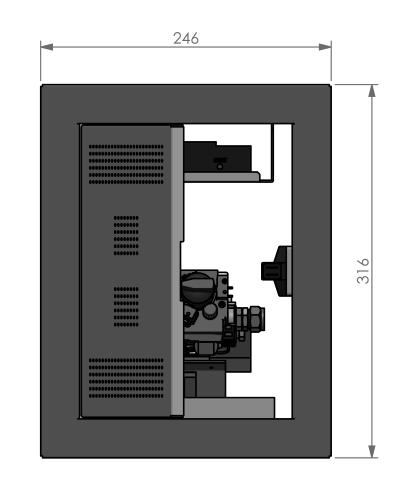
60 OPERATING UNIT 82
61 7 TECHNICAL DETAILS/REGULATIONS National installation regulations: Gas safety installation and use regulations 1998 plus all relevant safety and building regulations concerning fire installation Document J: Combustion appliances and fuel storage systems Model : VIEW BELL SMALL 3 CF (Centre Fire) Gas : NATURAL GAS : BUTANE / PROPANE Country : GB; Great Britain/IE; Ireland : GB; Great Britain/IE; Ireland Product identifi cation no : 0063CM3684 : 0063CM3684 Type of appliance under CE-norm : C 11 / C 31 / C 31S : C 11 / C 31 / C 31S Category of appliance : I 2H natural gas G20 : I 3B/P butane/propane G30/G31 Nominal heat input : 10.2 kw : Butane (G30) : 10.0 kw (Gross calorifi c value) Propane (G31) : 8.5 kw Nominal heat output : 7.9 kw : kw Effi ciency class : 1 (85%) : 1 (85%) NOx-class : 5 : 5 Gas rate (max.) : 0.97 m 3 /hr. : Butane (G30) : 750 gr/hr. s Propane (G31) : 620 gr/hr. Supply pressure : 20.0 mbar : Butane (G30) : 37.0 mbar Propane (G31) : 37.0 mbar Burner pressure (max.) Hot : 13.2 mbar(*) : 29.0 mbar(*) Burner pressure (max.) Cold : 12.5 mbar(**) : 29.0 mbar(**) Burner pressure (min.) : 1.0 mbar(***) : 1.0 mbar(***) Primary air inlet burner Rear : 1x Ø12.0 mm : 1x Ø20.0 +corner mm + 2x Ø5.0 mm Primary air inlet burner Front : 1x Ø12.0 mm : 1x Ø20,0 +corner mm + 2x Ø5.0 mm Gas regulator block (remote control) : Mertik GV 60 : Mertik GV 60 Main burner : Centre Fire 561x130 mm : Centre Fire 561x130 mm Main burner injector Rear : no 190 (= 1x Ø1.90 mm) : no 95 (= 1x Ø0.95 mm) Main burner injector Front : no 190 (= 1x Ø1.90 mm) : no 125 (= 1x Ø1.25 mm) Pilot light burner : SIT : SIT Pilot light burner injector : no 36 (SIT ) : no 23 (SIT ) Gas connection : 3/8 G / Ø12 mm : 3/8 G / Ø12 mm Concentric fl ue system connection : Ø100 mm - Ø150 mm or : Ø100 mm - Ø150 mm or Ø130 mm - Ø200 mm Ø130 mm - Ø200 mm 83
62 Model : VIEW BELL SMALL 3 CF (Centre Fire) Gas : NATURAL GAS : BUTANE / PROPANE Country : GB; Great Britain/IE; Ireland : GB; Great Britain/IE; Ireland Batteries remote control - Receiver : 4x 1.5V AA : 4x 1.5V AA - Hand-transmitter : 1x 9V block : 1x 9V block Weight: - Basis model: Hidden Door : 84 kg : 84 kg - Model: Hidden Door with 10 cm : 99 kg : 99 kg frame and mantle iron - Option: Convection package : 11 kg : 11 kg (*) : Both burners at maximum. Appliance is on temperature. (**) : Both burners at maximum. Appliance is cold. (***) : Both burners at minimum. Flue gas exhaust and combustion air supply: Roof-mounted outlet : Concentric fl ue system Ø100 mm - Ø150 mm. Rigid and/or fl exible. Horizontal wall outlet : Concentric fl ue system Ø130 mm - Ø200 mm. Rigid. With wall outlet, depending on the fl ue confi guration; Ø100 mm - Ø150 mm or Ø130 mm - Ø200 mm. Heat changing surface: Entire front of the appliance. 84
63 Model : VIEW BELL SMALL 3 LF (Line Fire) Gas : NATURAL GAS : BUTANE / PROPANE Country : GB; Great Britain/IE; Ireland : GB; Great Britain/IE; Ireland Product identifi cation no : 0063CM3684 : 0063CM3684 Type of appliance under CE-norm : C 11 / C 31 / C 31S : C 11 / C 31 / C 31S Category of appliance : I 2H natural gas G20 : I 3B/P butane/propane G30/G31 Nominal heat input : 11.7 kw : Butane (G30) : 11.5 kw (Gross calorifi c value) Propane (G31) : 9.5 kw Nominal heat output : 9.0 kw : kw Effi ciency class : 1 (85%) : 1 (85%) NOx-class : 5 : 5 Gas rate (max.) : 1.10 m 3 /hr. : Butane (G30) : 860 gr/hr. s Propane (G31) : 700 gr/hr. Supply pressure : 20.0 mbar : Butane (G30) : 37.0 mbar Propane (G31) : 37.0 mbar Burner pressure (max.) Hot : 11.2 mbar(*) : 29.0 mbar(*) Burner pressure (max.) Cold : 10.5 mbar(**) : 29.0 mbar(**) Burner pressure (min.) : 0.9 mbar(***) : 1.0 mbar(***) Primary air inlet burner Rear : 1x Ø12.0 mm : 1x Ø20.0 +corner mm + 2x Ø5.0 mm Primary air inlet burner Front : 1x Ø12.0 mm : 1x Ø20,0 +corner mm + 2x Ø5.0 mm Gas regulator block (remote control) : Mertik GV 60 : Mertik GV 60 Main burner : Line Fire 561x130 mm : Line Fire 561x130 mm Main burner injector Rear : no 190 (= 1x Ø1.90 mm) : no 110 (= 1x Ø1.10 mm) Main burner injector Front : no 230 (= 1x Ø2.30 mm) : no 130 (= 1x Ø1.30 mm) Pilot light burner : SIT : SIT Pilot light burner injector : no 36 (SIT ) : no 23 (SIT ) Gas connection : 3/8 G / Ø12 mm : 3/8 G / Ø12 mm Concentric fl ue system connection : Ø100 mm - Ø150 mm or : Ø100 mm - Ø150 mm or Ø130 mm - Ø200 mm Ø130 mm - Ø200 mm 85
64 Model : VIEW BELL SMALL 3 LF (Line Fire) Gas : NATURAL GAS : BUTANE / PROPANE Country : GB; Great Britain/IE; Ireland : GB; Great Britain/IE; Ireland Batteries remote control - Receiver : 4x 1.5V AA : 4x 1.5V AA - Hand-transmitter : 1x 9V block : 1x 9V block Weight: - Basis model: Hidden Door : 84 kg : 84 kg - Model: Hidden Door with 10 cm : 99 kg : 99 kg frame and mantle iron - Option: Convection package : 11 kg : 11 kg (*) : Both burners at maximum. Appliance is on temperature. (**) : Both burners at maximum. Appliance is cold. (***) : Both burners at minimum. Flue gas exhaust and combustion air supply: Roof-mounted outlet : Concentric fl ue system Ø100 mm - Ø150 mm. Rigid and/or fl exible. Horizontal wall outlet : Concentric fl ue system Ø130 mm - Ø200 mm. Rigid. With wall outlet, depending on the fl ue confi guration; Ø100 mm - Ø150 mm or Ø130 mm - Ø200 mm. Heat changing surface: Entire front of the appliance. 86
65 8 REPLACEMENT PARTS LIST When requesting service or ordering replacement parts, please quote the model type and serial number. All parts listed in this manual may be ordered from a Bellfi res dealer. No Article no Description Main burner Centre Fire 561 x 130 mm Natural gas G20 / Butane/Propane G30/G31 G20: 1x Ø12.0 mm front + 1x Ø12.0 mm rear G30/G31: 1x Ø20.0 +corner mm + 2x Ø5.0 mm front and 1x Ø20.0 +corner mm + 2x Ø5.0 mm rear Burner mat L = 561 mm Centre Fire Burner injector Natural gas; Front: no 190 (1x Ø1.90 mm) Burner injector Natural gas; Rear: no 190 (1x Ø1.90 mm) Burner injector Butane/Propane; Front: no 125 (1x Ø1.25 mm) Burner injector Butane/Propane; Rear: no 95 (1x Ø0.95 mm) Main burner Line Fire 561 x 130 mm Natural gas G20 / Butane/Propane G30/G31 G20: 1x Ø12.0 mm front + 1x Ø12.0 mm rear G30/G31: 1x Ø20.0 +corner mm + 2x Ø5.0 mm front and 1x Ø20.0 +corner mm + 2x Ø5.0 mm rear Burner mat L = 561 mm Line Fire Burner injector Natural gas; Front: no 230 (1x Ø2.30 mm) Burner injector Natural gas; Rear: no 190 (1x Ø1.90 mm) Burner injector Butane/Propane; Front: no 130 (1x Ø1.30 mm) Burner injector Butane/Propane; Rear: no 110 (1x Ø1.10 mm) Gas regulator block; GV 60 (M10 Thermocouple connection) /8 male x Ø12 Compression fi tting Nut Ø8 mm for burner supply GV 60 for front burner Olive Ø8 mm for burner supply GV 60 for front burner Gas valve rear burner Adapter 3/8 bsp x 3/8 + O-ring Nut Ø8 mm for gas valve rear burner Olive Ø8 mm for gas valve rear burner Cut-off nipple Ø4 mm GV Cable (sw): Receiver - Thermocouple interrupter, L = 500 mm Cable (tc): Receiver - Thermocouple interrupter, L = 500 mm Hand-held transmitter: Display screen: Temperature and two programmes Cover battery compartment hand-held transmitter - with imprint: Operating double burner Receiver GV 60 - EU Wire connecting cable Gas regulator block - Receiver, L = 500 mm Piezo ignition cable, 2x 2.8 x 0.8 mm, L = 1500 mm Thermocouple M mm Thermocouple interrupter M10 87
66 No Article no Description Pilot light set outer casing, Double fl ame Packing pilot light set outer casing Pilot light injector; Natural gas; no Pilot light injector; Butane/Propane; no Piezo electrode for pilot light, 2.8 x 0.5 mm Nut piezo electrode Nut thermocouple Pilot light olive; Ø4 mm, steel Pilot light nut; Ø4 mm, steel Pilot light pipe; Ø4 mm, L = 1500 mm, Flexible, Stainless steel Burner pipe; Ø8 mm, L = 1500 mm, Flexible, Stainless steel - 10 kw+, front burner Burner pipe; Ø8 mm, L = 1500 mm, Flexible, Stainless steel - 10 kw+, rear burner Nut; Ø8 mm, compression elbow main burner Olive; Ø8 mm, compression elbow main burner Glass View Bell Small 3 front (517 x 747,5 x 4 mm) Glass View Bell Small 3 side (517 x 328 x 4 mm) Tube ceramic glue Black fi bre glass tape 15 x 3 mm, adhesive Black fi bre glass tape 30 x 2 mm, adhesive Black fi bre glass tape 20 x 2 mm, adhesive Black fi bre glass cord Ø10 mm 88
INSTALLATION INSTRUCTIONS & MANUAL FOR MAINTENANCE DERBY LARGE 3 CF/LF. Gas fi re with closed combustion system
 INSTALLATION INSTRUCTIONS & MANUAL FOR MAINTENANCE DERBY LARGE 3 CF/LF Gas fi re with closed combustion system Bellfi res wishes you many cosy evenings with your new Bellfi res gas fi re This document
ROOM DIVIDER LARGE 3 CF/LF ROOM DIVIDER LARGE 3 L/R CF/LF
 INSTALLATION INSTRUCTIONS & MANUAL FOR MAINTENANCE ROOM DIVIDER LARGE 3 CF/LF ROOM DIVIDER LARGE 3 L/R CF/LF Gas fi res with closed combustion system Bellfi res wishes you many cosy evenings with your
CORNER BELL SMALL 3 CF/LF
 INSTALLATION INSTRUCTIONS & MANUAL FOR MAINTENANCE CORNER BELL SMALL 3 CF/LF Gas fi res with closed combustion system Bellfi res wishes you many cosy evenings with your new Bellfi res gas fi re This document
VIEW BELL VERTICAL 3 CF/LF
 INSTALLATION INSTRUCTIONS & MANUAL FOR MAINTENANCE VIEW BELL VERTICAL 3 CF/LF Gas fi res with closed combustion system Bellfi res wishes you many cosy evenings with your new Bellfi res gas fi re This document
INSTALLATION INSTRUCTIONS AND INSTRUCTIONS FOR USE. Wall-mounted gas fi re with closed combustion system FREE BELL
 INSTALLATION INSTRUCTIONS AND INSTRUCTIONS FOR USE Wall-mounted gas fi re with closed combustion system FREE BELL Bellfi res wishes you many cosy evenings with your new Bellfi res gas fi re This document
VENTO CLASSIC MEDIUM
 INSTRUCTIONS FOR USE & MANUAL DAILY MAINTENANCE VENTO CLASSIC MEDIUM Gas fi re with closed combustion system Bellfi res wishes you many cosy evenings with your new Bellfi res gas fi re This document is
Solution Installation guide
 Solution 40011444-1327 ENG Installation guide ENG 1-1 1-2 1-3 1.4 1 < < < < 2.1 2-3 2-4 2 < < < < 3-1 3.2 3-3 3.5 3.6 3 < < < < 4-1 A 4-2 4-3 4 < < < < Dimensions Terminal position Distance (For good working
Relaxed Premium M Relaxed Premium M ENG
 Relaxed Premium M 40010959 1440 Relaxed Premium M ENG 3 alternative finishes. 1.1a 1.1b 1.1c 1 < < < < 1.2 1.3 7 1.4 2 < < < < 1.5 1.6 B 1.9 3 < < < < 2.1 2.2 2.3 3.1 3.2 3.3 3.4 4 < < < < 3.5 4.1 4.2
Duet Premium M Duet Premium M ENG
 Duet Premium M 40011422-1441 Duet Premium M ENG 1.1 1.2 1.3 1.4 1.5 1.6 1.7 1.8 1 < < < < 2.1 a 2.1 b 2.1 c A C 2.2 2 < < < < F F 2.3 X H X C 2.4 2.5 S T 3.1 3.2 R Q 3.3 3 < < < < 4.1 4.2 4.3 4.4 4 <
Clear Installation guide
 Clear 40010631-0938 ENG Installation guide ENG 1.1 1.2 1.3 A 1.4 1.5 1 < < < < A B 2.1 2.2 2.3 C 2.4 2.5 2 < < < < 3.1 3.2 3-3 3 < < < < Inhoudsopgave 1 Introduction... 6 2 Safety instructions... 6 3 Installation
Fyn Installation guide
 Fyn 600 4001131-1123 ENG Installation guide ENG 1.1 1.2 A B 1.3 1.4 1 < < < < 2.1 2.2 2.3 2.4 3.1 3.2 2 < < < < 4.1 4.2 4.3 4.4 3 < < < < 1 Introduction The appliance can only be installed by a competent
Duet Premium L Duet Premium L ENG
 Duet Premium L 40011297-1441 Duet Premium L ENG 1.1 1.2 1.3 1.4 1.5 1.6 1.7 1.8 1 < < < < 2.1 a 2.1 b 2.1 c A C 2.2 2 < < < < F F 2.3 X H X C 2.4 2.5 S T 3.1 3.2 R Q 3.3 3 < < < < 4.1 4.2 4.3 4.4 4 <
Fyn Installation guide
 Fyn 450 400100929-1114 ENG Installation guide ENG 1.1 1.2 A B 1.3 1.4 1 < < < < 2.1 2.2 2.3 3.1 3.2 2 < < < < 4.1 4.2 4.3 4.4 3 < < < < Table of contents 1 Introduction... 6 2 Safety instructions... 6
Duet XL /0929. Installation guide
 Duet XL 40010749/0929 ENG Installation guide ENG 1.1 1.2 1.3 1.4 1.5 A 1.6 1.7 1 < < < < B A 2.1 2.2 2.3 2.4 2 < < < < 2.5 2.6 2.7 2.8 3 < < < < 3.1 F F 3.2 3.3 4 < < < < Table of contents 1 Introduction...
Respect OC Installation manual
 Respect OC 40011335-1235 ENG Installation manual ENG 1.1 1.2 A 1.3 1.4 A A 2.1 2.2 2.3 1 < < < < 2.4 2.5 B C A B A 2.6 2 < < < < 3.1 3.2 3.3 3.4 3.5 3.6 3 < < < < A B 3.7 4 < < < < L A A 4.1 A A 4.2 A
Vaska Logburner. voorbeeld Installation guide
 Vaska ogburner voorbeeld 40010627-2103 ENG Installation guide ENG 1.1 1.2 1.3 1.4 1.5 1 < < < < 1 Introduction The appliance can only be installed by a competent person in accordance with the Gas Safety.
INSTALLATION INSTRUCTIONS TD75. Vented tumble dryer DOMESTIC. Carefully read the instructions for use before using the dryer.
 INSTALLATION INSTRUCTIONS TD75 Vented tumble dryer DOMESTIC Carefully read the instructions for use before using the dryer. Dear Customer, Read these instructions carefully and completely before you install
INSTRUCTIONS FOR USE & MANUAL DAILY MAINTENANCE UNICA Gas fi re with open combustion system
 INSTRUCTIS FOR USE & MANUAL DAILY MAINTENANCE UNICA-2 75 Gas fi re with open combustion system Bellfi res wishes you many cosy evenings with your new Bellfi res gas fi re This document is an essential
Installation Manual EF5000 AUS & NZ
 Installation Manual EF5000 AUS & NZ This manual is ONLY for fires with a serial No. from 80600 to 80999. Important: The appliance shall be installed in accordance with; Local gas fitting regulations Municipal
GENERAL RULES. Ensure that the installation of your product conforms to all the indications given below. English CHIMNEY STACK
 1.0 GENERAL RULES DT2010216-05 Ensure that the installation of your product conforms to all the indications given below. Fig. 1 CHIMNEY STACK SINGLE FLUEWAY OR CHIMNEY CONNECTION TO FLUE SOOT INSPECTION
CRYSTAL FIRES. Inset Conventional Flue Fire. (BOSTON/MIAMI) Cf1 and MANHATTAN USER INSTALLATION AND SERVICING INSTRUCTIONS
 Cf1 and MANHATTAN USER INSTALLATION AND SERVICING INSTRUCTIONS") CRYSTAL FIRES (BOSTON/MIAMI) Cf1 and MANHATTAN Inset Conventional Flue Fire USER INSTALLATION AND SERVICING INSTRUCTIONS FOR USE WITH NATURAL GAS G20 @ 20 mbar For use in GB and IE CE THESE INSTRUCTIONS
CRYSTAL FIRES (BOSTON/MIAMI) Cf1 and MANHATTAN Inset Conventional Flue Fire USER INSTALLATION AND SERVICING INSTRUCTIONS FOR USE WITH NATURAL GAS G20 @ 20 mbar For use in GB and IE CE THESE INSTRUCTIONS
Installation Instructions Horizon Natural Draft Electronic Ignition Gas Fireplaces
 Installation Instructions Horizon Natural Draft Electronic Ignition Gas Fireplaces Installation Instructions Horizon Natural Draft Electronic Ignition 3 Sided Gas Fireplaces Natural Draft Electronic Ignition
INSTALLATION INSTRUCTIONS & MANUAL FOR ANNUAL MAINTENANCE CUATRO Wood-burning insert/built-in appliance
 INSTALLATION INSTRUCTIONS & MANUAL FOR ANNUAL MAINTENANCE CUATRO-3 90 Wood-burning insert/built-in appliance Barbas wishes you many cosy evenings with your new fi re This document is an essential part
FLAME HEATER PYRAMID CLFH-10SS OPERATION INSTRUCTIONS
 FLAME HEATER PYRAMID CLFH-10SS OPERATION INSTRUCTIONS www.colorato.net For outdoors use only Uses propane, butane or LPG only Reflector: 47x47 mm Total Height: 2250 mm Regulator s external pressure: 28-30
Evolve 951 & Product specification pages
 951 & 1250 Product specification pages SUPPORTING ASTHMA CARE Evolve Specification Evolve 951 Evolve 1250 Inbuilt power flued convection fan heater with electronic temperature control, timers, and remote.
INSTALLATION & USERS INSTRUCTIONS. FOR USE WITH NATURAL GAS 20 mbar For use in GB and IE
 1 valentine s buildings Bechers drive Aintree racecourse Business Park L9 5ay CF1 L GAS APPLIANCE INSET CONVENTIONAL FLUED GAS FIRE INSTALLATION & USERS INSTRUCTIONS FOR USE WITH NATURAL GAS G20 @ 20 mbar
ULTIMATE INSET LIVE FUEL EFFECT GAS FIRE MODEL 417 OWNER GUIDE
 ULTIMATE INSET LIVE FUEL EFFECT GAS FIRE MODEL 417 OWNER GUIDE THE NATURAL GAS MODEL IS FOR G20 AT A SUPPLY PRESSURE OF 20mbar THE PROPANE GAS MODEL IS FOR G31 AT A SUPPLY PRESSURE OF 37mbar THESE APPLIANCES
FOR YOUR SAFETY FOR OUTDOOR USE ONLY PROPANE GAS. Model No. AH2069ODS, AH2063ODS
 Model No. AH2069ODS, AH2063ODS The ideal solution for extending the season of outdoor entertaining Creates a stylish and attractive ambience Direct ignition Includes a safety tip-over switch that halts
Dovre 250 Cast Iron Gas Stove
 Dovre 50 Cast Iron Gas Stove NATURAL GAS AND LPG INSTALLATION, SERVICING AND USER INSTRUCTIONS THIS PRODUCT IS FOR USE ONLY IN GREAT BRITAIN AND IRELAND These instructions are to be left with the customer,
Torch framed Installation Guide
 Torch framed 40010567-0602 Installation Guide 1 2 3 4 1 < < < < 5 6 7 > > > > 2 Content 1 Introduction... 1 2 Safety Instructions... 2 3 Installation requirements... 3 3.1 Rear surface construction...
Installation Manual EF5000 NZ
 Installation Manual EF5000 NZ Important: The appliance shall be installed in accordance with; Local gas fitting regulations Municipal building codes AS/NZS 5601.1.1:2010 Gas Installation Any other relevant
VASKA C11. gas -fireplace installation guide
 VASKA C11 gas -fireplace installation guide Saturnus 8 NL-8448 CC Heerenveen Postbus 219 NL-8440 AE Heerenveen T. +31(0)513 656500 F. +31(0)513 656501 40 010 459 01 51 DESCRIPTION OF THE FIREPLACE CONTENTS
UNILUX Three-sided
 INSTALLATION INSTRUCTIONS & MANUAL FOR ANNUAL MAINTENANCE UNILUX-6 265 Three-sided Wood-burning insert appliance Barbas wishes you many cosy evenings with your new fi re This document is an essential part
Installation and Operating Instructions
 Installation and Operating Instructions Models: Verso 4G Hob As part of Parmco Appliances commitment to improving and updating product ranges, we reserve the right to alter, change and update technical
PowerVent. Installation manual (GB) English. Store this document in a safe place UK
 English. Store this document in a safe place UK") PowerVent Installation manual (GB) Store this document in a safe place 959.034.03.UK GB Contents Blz Foreword 3 1. Introduction 3 2. CE declaration 4 3. SAFETY 4 3.1 General 4 3.2 Regulations 4 3.3 Precautions
PowerVent Installation manual (GB) Store this document in a safe place 959.034.03.UK GB Contents Blz Foreword 3 1. Introduction 3 2. CE declaration 4 3. SAFETY 4 3.1 General 4 3.2 Regulations 4 3.3 Precautions
Baxi Brazilia F5, F5S & F8S
 Baxi Brazilia F5, F5S & F8S Balanced Flue Gas Wall Heaters Comp No. 243469 - Iss 1-6/99 Installation and Servicing Instructions Natural Gas Baxi Brazilia F 5 G.C.No. 35 075 0lA Baxi Brazilia F 5S Grey
INSTALLATION, USERS AND SERVICING INSTRUCTIONS
 INSTALLATION, USERS AND SERVICING INSTRUCTIONS SLIMLINE (FAN FLUE) HOTBOX Inset Decorative coal or pebble effect Gas Fire For use with Natural Gas (G20) @ 20mbar or Butane (G30) @ 28mbar or Propane (G31)
COAL EFFECT BALANCED FLUE GAS FIRE
 Raglan COAL EFFECT BALANCED FLUE GAS FIRE Installation and Maintenance Instructions Hand these instructions to the user Model No. KBFC**MN for use on Natural Gas (G20) at a supply pressure of 20 mbar in
HAWK GAS STOVE. Installation and Servicing Instructions
 HAWK GAS STOVE Installation and Servicing Instructions Please leave this instruction booklet with the user after the installation is complete. Leave the system ready for operation and instruct the user
USERS, INSTALLATION AND SERVICING INSTRUCTIONS
 USERS, INSTALLATION AND SERVICING INSTRUCTIONS GAS BRATT PAN G3800 and G3800DX DATE PURCHASED: MODEL NUMBER: SERIAL NUMBER: DEALER: SERVICE PROVIDER: T100753 Rev. 3 Published: 04 /10/2012 Dear Customer,
INSTALLATION INSTRUCTIONS & MANUAL FOR ANNUAL MAINTENANCE UNIVERSAL Wood-burning insert appliance
 INSTALLATION INSTRUCTIONS & MANUAL FOR ANNUAL MAINTENANCE UNIVERSAL-6 80 Wood-burning insert appliance Barbas wishes you many cosy evenings with your new fi re This document is an essential part of your
ATHENA R.S. LPG. Room Sealed Inset Live Fuel Effect Gas Fire. PRODUCT No. A99011 G.C. No Installation and Servicing Instructions
 ATHENA R.S. LPG Room Sealed Inset Live Fuel Effect Gas Fire PRODUCT No. A99011 G.C. No. 32-170-18 Installation and Servicing Instructions CE MARKED FOR USE IN G.B. & I.E. LEAVE THESE INSTRUCTIONS WITH
LUNA 850 V GOLD GAS INSTRUCTION FOR INSTALLATION AND USE. Passion for fire
 LUNA 850 V GOLD GAS INSTRUCTION FOR INSTALLATION AND USE Passion for fire SUMMARY 1. GENERAL REMARKS...3 2. CONNECTION...3 3. SPECIFICATION SHEET...4 4. ASSEMBLY OF THE CHIMNEY...5-7 5. ELECTRICAL CONNECTION...8
This appliance must be installed and serviced by a competent person as stipulated by the Gas Safety (Installation & Use) Regulations.
 Regulations.") G3512 and G3532 DOMINATORPLUS Grills INSTALLATION and SERVICING INSTRUCTIONS This appliance must be installed and serviced by a competent person as stipulated by the Gas Safety (Installation & Use) Regulations.
G3512 and G3532 DOMINATORPLUS Grills INSTALLATION and SERVICING INSTRUCTIONS This appliance must be installed and serviced by a competent person as stipulated by the Gas Safety (Installation & Use) Regulations.
Orchestra COAL EFFECT BALANCED FLUE GAS FIRE
 Orchestra COAL EFFECT BALANCED FLUE GAS FIRE Installation and Maintenance Instructions Hand these instructions to the user Model No s FBFN76G & FBFN98G are for use on Natural Gas (G20) at a supply pressure
PVK-80 Power Vent - Installation Instructions -
 PVK-80 Power Vent - Installation Instructions - PVK-80 POWERVENT IMPORTANT: Failure to read and follow these instructions may create a possible hazard and will void the fi replace warranty. THESE INSTRUCTIONS
SURE HEAT MANUFACTURING
 SURE HEAT MANUFACTURING Installation and Operating Instructions for NATURAL & L.P. GAS A.G.A. SINGLE & DUAL BURNER VENTED UNITS Model: RP (8,24,30)-N GO (8,24,30)-N GLO (8,24,30)-N WO (8,24,30)-N CO (8,24,30)-N
Kalahari DECORATIVE FUEL EFFECT GAS FIRE
 Kalahari DECORATIVE FUEL EFFECT GAS FIRE User Instructions These instructions should be read by the user before operating the appliance and retained for future reference Model No. KRDC00MN & KRDC00SN are
Installation and service must be provided by a qualified installer, service agency or the gas supplier.
 INSTALLATION AND OPERATION GUIDE FOR OLDE WORLD BASKET Vented Decorative Appliance For all models tested through PFS Corporation, to ANSI Z21.60-2003/CGA 2.26-2003, Decorative Appliance for Installation
HG 675 CX 60 HG 675 CN 60 HG 675 CW 60
 HG 675 X 60 HG 675 CX 60 HG 675 CN 60 HG 675 CW 60 1 2 1. : 93/68: 90/396: 2006/95/CE: 2004/108/CE: - 1935/2004:. 2002/95/CE: RoHS 2.,.,,,,...,. (,..)..,,.,. ( ),,, ;,,.,.....,.,,,,,,...,. (..),,.,..,.,,,,
Installation & Service Instructions
 Part No. 966/9350/1 02 Potterton Housewarmer Illusion ASD - G.C. NO. 37 590 16 966 Inset DGF with ILLUSION FACIA Potterton Housewarmer Stratton ASD - G.C. NO. 37 590 17 966 Inset DGF with STRATTON FACIA
Table Top Patio Heater
 Table Top Patio Heater INSTRUCTION MANUAL MODEL: HPS-B Certified by international recognized standards. The infra-red with heat wave outdoor heater. Variable control gas valve with electric push igniter.
THE INSTRUCTIONS IN THIS MANUAL APPLY TO KENT GAS FIRES. CONTENTS:-
 THE INSTRUCTIONS IN THIS MANUAL APPLY TO KENT GAS FIRES. THE MODELS COVERED ARE:- For use with Natural Gas:- KENT ESTATE NG, KENT ULTIMA NG For use with Liquid Propane Gas (LPG):- KENT ESTATE LP, KENT
Area Heater AH100 Series
 Area Heater AH100 Series FEATURES: The ideal solution for extending the season for outdoor entertaining Creates a stylish and attractive ambience Casts an approximate 3 to 5 metre circle of radiant sun-like
Clarendon and Ashdon Log Effect Stove Range
 Clarendon and Ashdon Log Effect Stove Range Conventional Flue With upgradeable control valve Instructions for Use, Installation and Servicing For use in GB, IE (Great Britain and Eire) This appliance has
MODEL 466 Radiant / Convector Gas Fire Black Beauty
 O W N E R G U I D E MODEL 466 Radiant / Convector Gas Fire Black Beauty This Owner Guide is intended to help you care for your Valor gas fire. Please read carefully before using your gas fire and keep
Wok Cookers Instruction Manual
 Wok Cookers Instruction Manual Part No. DC100-09 Single Burner Wok Cooker Part No. DC200-09 Double Burner Wok Cooker IMPORTANT It is IMPORTANT that you read these instructions carefully and understand
Wood Fires Take a look at the other brochure... Gas Fires
 Wood Fires Wood fires with a sliding door Slide Bell 2008 Bellfi res exclusive in every detail Whether your taste is for refi ned classic or stark modern, a Bellfi res fi re is always the choice for the
C D INSTALLATION 16 INSTALLER GENERAL INFORMATION
 INSTALLATION GENERAL INFORMATION This appliance is sealed from the surrounding environment in which it is installed and consequently combustion air is only aspired from outside! - When installing, NEVER
Decorative Fuel Effect Appliances
 Decorative Fuel Effect Appliances Technical Manual User and Installation Instructions for CUBB22US Available in Natural Gas. 1 Contents Section Pages 1 Unpacking 3 2 Installation Parameters 4 3 Installation
Operating and Installation Instructions for CRAMER COE Gas Cooker
 Operating and Installation Instructions for CRAMER COE Gas Cooker Models: COE-C COE-CG COE-CGO COE-FULL COE-C-DUFU COE-CG-DUFU COE-CGO-DUFU COE-FULL-DUFU Cooker (4 gas burners) Cooker + grill (4 gas burners)
MULTIPOINT BF Gas Fired Balanced Flue Water Heater
 Please leave these instructions with the user MULTIPOINT BF Gas Fired Balanced Flue Water Heater User Operating, Installation and Servicing Instructions 6 720 607 090 (03.12) JS Natural Gas Main Multipoint
These Appliances must be installed and serviced by a competent person as stipulated by the Gas Safety (Installation & Use) Regulations.
 Regulations.") G350/11 and 12 FREESTANDING FRYERS INSTALLATION and SERVICING INSTRUCTIONS These Appliances must be installed and serviced by a competent person as stipulated by the Gas Safety (Installation & Use) Regulations.
G350/11 and 12 FREESTANDING FRYERS INSTALLATION and SERVICING INSTRUCTIONS These Appliances must be installed and serviced by a competent person as stipulated by the Gas Safety (Installation & Use) Regulations.
OWNER S GUIDE ETERNITY. MODEL 540C (GC No ) INSET BALANCED FLUE GAS FIRE
 INSET BALANCED FLUE GAS FIRE") 600B637/02 ETERNITY MODEL 540C (GC No. 32-032-19) INSET BALANCED FLUE GAS FIRE THIS APPLIANCE IS FOR USE WITH NATURAL GAS (G20) THIS APPLIANCE IS FOR USE IN THE UNITED KINGDOM (GB) AND THE REPUBLIC OF
600B637/02 ETERNITY MODEL 540C (GC No. 32-032-19) INSET BALANCED FLUE GAS FIRE THIS APPLIANCE IS FOR USE WITH NATURAL GAS (G20) THIS APPLIANCE IS FOR USE IN THE UNITED KINGDOM (GB) AND THE REPUBLIC OF
Service Manual For model N260 - a 2.4 cu. ft., 2-way refrigerator. For model N a 2.4 cu. ft., 3-way refrigerator.
 Service Manual For model N260 - a 2.4 cu. ft., 2-way refrigerator. For model N260.3 - a 2.4 cu. ft., 3-way refrigerator. NORCOLD, Inc. P.O. Box 4248 Sidney, OH 45365-4248 Part No. 619260A (4-98) Table
VASKA B11. gas -fireplace installation guide
 VASKA B11 gas -fireplace installation guide Saturnus 8 NL-8448 CC Heerenveen Postbus 219 NL-8440 AE Heerenveen T. +31(0)513 656500 F. +31(0)513 656501 40 010 446 01 51 DESCRIPTION OF THE FIREPLACE CONTENTS
P45 VENTED BURNER SYSTEMS (MANUALLY LIGHTED)
") INSTALLATION & OWNER S MANUAL Burner Systems: P45-18 P45-24 P45-30 For use with natural gas only (Shown installed with Fyre Spheres) DESIGN CERTIFIED to Manually Lighted, Vented Decorative Appliance ANSI
INSTALLATION & OWNER S MANUAL Burner Systems: P45-18 P45-24 P45-30 For use with natural gas only (Shown installed with Fyre Spheres) DESIGN CERTIFIED to Manually Lighted, Vented Decorative Appliance ANSI
Curvation & Siesta Models
 Curvation & Siesta Models Installation, Servicing & User Instructions For use in GB & IE (United Kingdom and Ireland) This appliance has been tested and certified for other counties (see technical data).
5traxo INSTALLATION AND SERVICING INSTRUCTIONS MANDATORY REQUIREMENTS INSTALLATION
 5traxo Division of Legge Fabheat Ltd Longfield Road, Sydenham, Leamington Spa CV31 1XB Tel. (0926) 882233 Fax (0926) 450846 Registered in England No. 500091 Universal INSTALLATION AND SERVICING INSTRUCTIONS
Wall-mounted Gas Fires. 39 Portrait INSTALLATION,USER & SERVICING INSTRUCTIONS (TO BE LEFT WITH THE CUSTOMER) UK & IRELAND
 UK & IRELAND") Wall-mounted Gas Fires 39 Portrait INSTALLATION,USER & SERVICING INSTRUCTIONS (TO BE LEFT WITH THE CUSTOMER) UK & IRELAND UK IE INSTALLATION INSTRUCTIONS CONTENTS Important Notes Page 2 Commissioning the
Wall-mounted Gas Fires 39 Portrait INSTALLATION,USER & SERVICING INSTRUCTIONS (TO BE LEFT WITH THE CUSTOMER) UK & IRELAND UK IE INSTALLATION INSTRUCTIONS CONTENTS Important Notes Page 2 Commissioning the
INSTALLATION AND OPERATION MANUAL GAS SALAMANDER G91 G91B. For use in GB & IE
 om INSTALLATION AND OPERATION MANUAL GAS SALAMANDER G91 G91B For use in GB & IE 231920-11 MANUFACTURED BY Moffat Limited Rolleston 7675 New Zealand INTERNATIONAL CONTACTS AUSTRALIA Moffat Pty Limited Web:
FREESTANDING GAS HEATER
 FREESTANDING GAS HEATER July 2001 OPERATIONS, MAINTENANCE & WARRANTY INFORMATION 25-07-01 Page 1 of 23 Operation Instructions for Eros Free Standing Gas Fire July 2001.doc CONTENTS: PAGE INTRODUCTION 3
INSTRUCTIONS MANUAL FOR USE AND MAINTENANCE
 INSTRUCTIONS MANUAL FOR USE AND MAINTENANCE Carbel models: C-60 Plus C-70 Plus C-80 Plus C-100 Plus C-70 Plus Double-sided C-80 Plus Double-sided C-100 Plus Double-sided CARBEL C/ Ciudad de Cartagena,
Charlotte CRT20AB, Charlotte CRT20BR & Brookline BKL20
 Charlotte CRT20AB, Charlotte CRT20BR & Brookline BKL20 08/51007/0 Issue 1 The product complies with the European Safety Standards EN60335-2-30 and the European Standard Electromagnetic Compatibility (EMC)
Metro 70 - Metro 70 Tunnel
 Metro 70 - Metro 70 Tunnel G31 propane Instructions for installation (GB / IE) Please retain this document carefully UK Contents page Foreword 2 1. Introduction 3 2. EC Declaration of Conformity 3 3. SAFETY
Gas Cooktops (450mm Wide Hobs)
") Installation and Operation Manual Gas Cooktops (450mm Wide Hobs) Series RN8450G RNL8450G RNB8450G RNLB8450G RN8900G RNL8900G RNB8900G RNLB8900G Date Purchased Serial Number Dealer Service Provider For
Installation and Operation Manual Gas Cooktops (450mm Wide Hobs) Series RN8450G RNL8450G RNB8450G RNLB8450G RN8900G RNL8900G RNB8900G RNLB8900G Date Purchased Serial Number Dealer Service Provider For
(manual control) (ezi-slide control) INSET COAL EFFECT GAS CONVECTOR FIRE V1/100/B INSTALLATION & USER INSTRUCTIONS
 (ezi-slide control) INSET COAL EFFECT GAS CONVECTOR FIRE V1/100/B INSTALLATION & USER INSTRUCTIONS") Model Number: V1/100/A V1/100/B (manual control) (ezi-slide control) INSET COAL EFFECT GAS CONVECTOR FIRE INSTALLATION & USER INSTRUCTIONS GB IE SUITABLE FOR USE ON NATURAL GAS (G20) AT 20mbar SUPPLY PRESSURE
Model Number: V1/100/A V1/100/B (manual control) (ezi-slide control) INSET COAL EFFECT GAS CONVECTOR FIRE INSTALLATION & USER INSTRUCTIONS GB IE SUITABLE FOR USE ON NATURAL GAS (G20) AT 20mbar SUPPLY PRESSURE
STRATA BATTERY IGNITION RADIANT CONVECTOR GAS FIRE
 STRATA BATTERY IGNITION RADIANT CONVECTOR GAS FIRE Installation, Maintenance & User Instructions Hand these instructions to the user Model No s FORS**EN are for use on Natural Gas (G20) at a supply pressure
MODEL 466 Radiant / Convector Gas Fire Black Beauty
 I N S T A L L E R G U I D E MODEL 466 Radiant / Convector Gas Fire Black Beauty Please keep in a safe place for future reference 600A734/02 Please leave this Installer Guide with the user This appliance
OWNER GUIDE. Sunfire II Radiant. Radiant / Convector Gas Fire. Model 347 (G. C. Number )
") 5110946/01 OWNER GUIDE Sunfire II Radiant Radiant / Convector Gas Fire Model 347 (G. C. Number 32-032-62) THIS APPLIANCE IS FOR USE WITH NATURAL GAS (G20) THIS APPLIANCE IS SUITABLE ONLY FOR INSTALLATION
5110946/01 OWNER GUIDE Sunfire II Radiant Radiant / Convector Gas Fire Model 347 (G. C. Number 32-032-62) THIS APPLIANCE IS FOR USE WITH NATURAL GAS (G20) THIS APPLIANCE IS SUITABLE ONLY FOR INSTALLATION
Synergy Grill User & Engineer Installation & Conversion Guide
 Synergy Grill 1300 User & Engineer Installation & Conversion Guide 1 Index: Description Page Number/Section Important Information 3 Installation 4-6 / Section 1 Commissioning 6 / Section 2 Converting Gas
Manual. P36D Gas Log Fireplace. Owners & Installation PLEASE KEEP THESE INSTRUCTIONS FOR FUTURE REFERENCE. Models: P36D-NG2 P36D-LPG2
 Owners & Installation P36D Gas Log Fireplace Manual LISTINGS AND CODE APPROVALS These gas appliances have been tested in accordance with AS4553, NZS 5262 and have been certified by the Australian Gas Association
JANUS 3 CIRCULATOR WATER HEATER INSTALLATION, COMMISSIONING & SERVICING INSTRUCTIONS G.C. No
 JANUS 3 CIRCULATOR WATER HEATER INSTALLATION, COMMISSIONING & SERVICING INSTRUCTIONS G.C. No 53 416 06 Publication No. ZZ 180/17 May 2000 These appliances are tested and certified by B G Technology for
INSTALLATION AND OPERATING MANUAL
 dickinson since 1932 MODEL 00-NEW-P12000 INSTALLATION AND OPERATING MANUAL Manufactured by: Dickinson Marine (1997) Ltd, 407-204 Cayer Street, Coquitlam, British Columbia, Canada V3K 5B1 www.ahoycaptain.com
Full Depth Convector MC / SC
 Full Depth Convector MC / SC COAL EFFECT GAS FIRE Installation and Maintenance Instructions Hand these instructions to the user Model No s MICC**MN & MICC**SN are for use on Natural Gas (G20) at a supply
Installation & Operating Instructions For LPG Q5 Stoves IGNITE 5 GAS STOVE (CD1) HEREFORD 5 GAS STOVE (CD2) DESIRE 5 GAS STOVE (SD1) Manual Control
 HEREFORD 5 GAS STOVE (CD2) DESIRE 5 GAS STOVE (SD1) Manual Control") Installation & Operating Instructions For LPG Q5 Stoves IGNITE 5 GAS STOVE (CD1) HEREFORD 5 GAS STOVE (CD2) DESIRE 5 GAS STOVE (SD1) Manual Control Conventional, Top or Rear Flue, LPG Gas Stove PLEASE
Installation & Operating Instructions For LPG Q5 Stoves IGNITE 5 GAS STOVE (CD1) HEREFORD 5 GAS STOVE (CD2) DESIRE 5 GAS STOVE (SD1) Manual Control Conventional, Top or Rear Flue, LPG Gas Stove PLEASE
IDE 20 / IDE 30 / IDE 50 IDE 60 / IDE 80
 IDE 20 / IDE 30 / IDE 50 IDE 60 / IDE 80 EN OPERATING MANUAL OIL HEATER TRT-BA-IDE20-30-50-60-80-TC-001-EN Table of contents Information on the use of this manual... 1 Scope of delivery... 1 General safety...
Corn Flame Energy Corn Stove Model 3000
 Corn Flame Energy Corn Stove Model 3000 Installation and Operation Guide Read thoroughly before starting installation Save this manual for future reference SAFETY NOTICE If this stove is not properly installed,
Propane Heater REMKO PGM 30 REMKO PGM 60
 Propane Heater REMKO PGM 30 REMKO PGM 60 Operation Technology Spare Parts Edition GB L07 REMKO strong as a bear. Operating instructions Make sure to read these instructions carefully before starting/using
Sonnet Plus Anthem Genesis Soraya
 5110524/01 OWNER GUIDE Sonnet Plus Anthem Genesis Soraya Model 747 (GC No. 32-032-51) INSET LIVE FUEL EFFECT GAS FIRE THIS APPLIANCE IS FOR USE WITH NATURAL GAS (G20) WHEN CONVERTED USING CONVERSION KIT
INSTALLATION AND OPERATION MANUAL GAS SALAMANDER G91 G91B. For use in GB & IE
 INSTALLATION AND OPERATION MANUAL GAS SALAMANDER G91 G91B For use in GB & IE 231920-8 MANUFACTURED BY Moffat Limited Christchurch New Zealand INTERNATIONAL CONTACTS AUSTRALIA Moffat Pty Limited Web: www.moffat.com.au
Sonnet Plus Anthem Genesis Soraya
 5108617/01 OWNER GUIDE Sonnet Plus Anthem Genesis Soraya Model 746 (GC No. 32-032-57) INSET LIVE FUEL EFFECT GAS FIRE THIS APPLIANCE IS FOR USE WITH NATURAL GAS (G20) WHEN CONVERTED USING CONVERSION KIT
Limours. Balanced Flue Room Heater MODEL NUMBER : KBFP00RN INSTALLATION, USER AND SERVICING INSTRUCTIONS THESE INSTRUCTIONS MUST REMAIN WITH THE USER
 Limours Balanced Flue Room Heater MODEL NUMBER : KBFP00RN INSTALLATION, USER AND SERVICING INSTRUCTIONS THESE INSTRUCTIONS MUST REMAIN WITH THE USER This appliance is suitable for use on Natural Gas (G20)
STUDIO Conventional Flue
 STUDIO Conventional Flue Instructions for Use, Installation and Servicing For use in GB, IE (Great Britain and Eire) This appliance has been certified for use in countries other than those stated. To install
Balanced Flue Gas Stoves Phoenix 3 Serial No:
 Balanced Flue Gas Stoves Phoenix 3 Serial No: INSTALLATION, SERVICING AND USER INSTRUCTIONS For use in GB & IE (United Kingdom and Ireland) This appliance has been tested and certified for other counties
SG Burner Only
 SG 700-780-900-1100 Burner Only SG Gas Burner into a Warmington SI Wood Open Fire Installation Guide Only Warmington SI Open Wood Firebox. Warmington SG Gas Burner. Traditional Grate & Burner Pure Grate
Model RF24DN/DP Direct Vent Fireplace Insert Installation and Owner s Manual
 Patents Pending Model RF24DN/DP Direct Vent Fireplace Insert Installation and Owner s Manual INSTALLER: Leave this manual with the appliance. CONSUMER: Retain this manual for future reference. Please read
Proline GAS HOB Model TCG40IX Instruction Book
 Proline GAS HOB Model TCG40IX Instruction Book GB Operating and Installation Instructions Index Technical data and specifications...... 3 Installation...................... 3-6 Ventilation........................
Pizza Oven with Stand
 Pizza Oven with Stand Cooks up to 3 pizzas at a time Use to cook a variety of food Easy clean vitreous enamel interior Model No. P0104 Powerful 22MJ/h stainless steel burner Viewing window and temperature
THE INSTRUCTIONS IN THIS MANUAL APPLY TO MASPORT BOSTON (Flued) AND CALGARY (Flueless) GAS FIRES.
 AND CALGARY (Flueless) GAS FIRES.") THE INSTRUCTIONS IN THIS MANUAL APPLY TO MASPORT BOSTON (Flued) AND CALGARY (Flueless) GAS FIRES. THE MODELS COVERED ARE:- MG 3000 STD NG, and MG 3000 FLS NG for use with Natural Gas MG 3000 STD LP, and
THE INSTRUCTIONS IN THIS MANUAL APPLY TO MASPORT BOSTON (Flued) AND CALGARY (Flueless) GAS FIRES. THE MODELS COVERED ARE:- MG 3000 STD NG, and MG 3000 FLS NG for use with Natural Gas MG 3000 STD LP, and