Service Manual "P" SERIES 30K - 36K 220V INVERTER-DRIVEN AIR CONDITIONING UNITS IMPORTANT:
|
|
|
- Basil Sparks
- 5 years ago
- Views:
Transcription

1 Service Manual "P" SERIES 30K - 36K 220V INVERTER-DRIVEN AIR CONDITIONING UNITS Type INDOOR UNIT Model DHP30NWB21S DCP30NWB21S DHP36NWB21S DCP36NWB21S Type OUTDOOR UNIT Model DHP30CSB21S DCP30CSB21S DHP36CSB21S DCP36CSB21S IMPORTANT: READ AND UNDERSTAND THIS MANUAL BEFORE USING THIS INVERTER- DRIVEN AIR CONDITIONING UNIT. KEEP THIS MANUAL FOR FUTURE REFERENCE.
2 Important Notice Johnson Controls, Inc. pursues a policy of continuing improvement in design and performance in its products. As such, Johnson Controls, Inc. reserves the right to make changes at any time without prior notice. Johnson Controls, Inc. cannot anticipate every possible circumstance that might involve a potential hazard. This inverter air conditioning unit is designed for standard air conditioning applications only. Do not use this unit for anything other than the purposes for which it was intended for. The installer and system specialist shall safeguard against leakage in accordance with local pipefitter and electrical codes. The following standards may be applicable, if local regulations are not available. International Organization for Standardization: (ISO 5149 or European Standard, EN 378). No part of this manual may be reproduced in any way without the expressed written consent of Johnson Controls, Inc. This inverter-driven (cooling or heat pump) air conditioning unit will be operated and serviced in the United States of America and comes with all required Safety, Danger, and Caution, warnings. If you have questions, please contact your distributor or dealer. This manual provides common descriptions, basic and advanced information to maintain and service this inverter-driven (cooling or heat pump) air conditioning unit which you operate, as well for other models. This inverter-driven (cooling or heat pump) air conditioning unit has been designed for a specific temperature range. For optimum performance and long life, operate this unit within range limits. This manual should be considered as a permanent part of the air conditioning equipment and should remain with the air conditioning equipment. Product Inspection upon Arrival 1. Upon receiving this product, inspect it for any damages incurred in transit. Claims for damage, either apparent or concealed, should be filed immediately with the shipping company. 2. Check the model number, electrical characteristics (power supply, voltage, and frequency rating), and any accessories to determine if they agree with the purchase order. 3. The standard utilization for this unit is explained in these instructions. Use of this equipment for purposes other than what it designed for is not recommended. 4. Please contact your local agent or contractor as any issues involving installation, performance, or maintenance arise. Liability does not cover defects originating from unauthorized modifications performed by a customer without the written consent of Johnson Controls, Inc. Performing any mechanical alterations on this product without the consent of the manufacturer will render your warranty null and void. 2 P
3 Table of Contents Safety Summary...i 1. Models Specifications Specification Sheet Operation Characteristic Curve Capacity Variation Ratio According to Temperature Noise Curve Cooling and Heating Data Sheet in Rated Frequency Outline Dimension Diagram Indoor Unit Outdoor Unit Refrigerant System Diagram Electrical Part Wiring Diagram PCB Printed Diagram Function and Control Remote Controller Introduction Brief Description of Modes and Functions Wired Zone Controller Troubleshooting Flashing LED of Indoor/Outdoor Unit and Primary Judgement How to Check the Main Part s Troubleshooting for Normal Malfunction Removal Procedures Removal Procedures of Indoor Unit Removal Procedures of Outdoor Unit...70 Appendix...76 Appendix 1: Reference Sheet of Celsius and Fahrenheit...76 Appendix 2: Configuration of Connection Pipe...76 Appendix 3: Pipe Flaring Method Appendix 4: List of Resistance for Temperature Sensor...78 Customer Support...81 Table of contents
4 1. Introduction This manual concentrates on inverter-driven cooling or heat pump air conditioning units. Read this manual carefully before installation. This manual should be considered as a permanent part of the air conditioning equipment and should remain with the air conditioning equipment. 2. Important Safety Instructions Safety Messages Indicates a hazardous situation that, if not avoided, could result in death or serious injury. Indicates a hazardous situation that, if not avoided, could result in minor or moderate injury. General Precautions Indicates information considered important, but not hazard-related (for example, messages relating to property damage). To reduce the risk of serious injury or death, read these instructions thoroughly and follow all warnings or cautions included in all manuals that accompanied the product and are attached to the unit. Refer back to these safety instructions as needed. This system should be installed by personnel certified by Johnson Controls, Inc. Personnel must be qualified according to local, state and national building and safety codes and regulations. Incorrect installation could cause leaks, electric shock, fire or explosion. In areas where Seismic Performance requirements are specified, the appropriate measures should be taken during installation to guard against possible damage or injury that might occur in an earthquake if the unit is not installed correctly, injuries may occur due to a falling unit. Use appropriate Personal Protective Equipment (PPE), such as gloves and protective goggles and, where appropriate, have a gas mask nearby. Also use electrical protection equipment and tools suited for electrical operation purposes. Keep a quenching cloth and a fire extinguisher nearby during brazing. Use care in handling, rigging, and setting of bulky equipment. When transporting, be careful when picking up, moving and mounting these units. Although the unit may be packed using plastic straps, do not use them for transporting the unit from one location to another. Do not stand on or put any material on the unit. Get a partner to help, and bend with your knees when lifting to reduce strain on your back. Sharp edges or thin aluminum fins on the air conditioner can cut fingers, so wear protective gloves. Do not touch or adjust any safety devices inside the indoor or outdoor units. All safety features, disengagement, and interlocks must be in place and functioning correctly before the equipment is put into operation. If these devices are improperly adjusted or tampered with in any way, a serious accident can occur. Never bypass or jump-out any safety device or switch. Johnson Controls, Inc. will not assume any liability for injuries or damage caused by not following steps outlined or described in this manual. Unauthorized modifications to Johnson Controls products are prohibited as they May create hazards which could result in death, serious injury or equipment damage. Will void product warranties. May invalidate product regulatory certifications. May violate OSHA standards. 31 P i
5 Take the following precautions to reduce the risk of property damage. Be careful that moisture, dust, or variant refrigerant compounds not enter the refrigerant cycle during installation work. Foreign matter could damage internal components or cause blockages. If air filters are required on this unit, do not operate the unit without the air filter set in place. If the air filter is not installed, dust may accumulate and breakdown may result. Do not install this unit in any place where silicon gases can coalesce. If the silicon gas molecules attach themselves to the surface of the heat exchanger, the finned surfaces will repel water. As a result, any amount of condensate can overflow from the condensate pan and could run inside of the electrical box, possibly causing electrical failures. When installing the unit in a hospital or other facility where electromagnetic waves are generated from nearby medical and/or electronic devices, be prepared for noise and electronic interference Electromagnetic Interference (EMI). Do not install where the waves can directly radiate into the electrical box, controller cable, or controller. Inverters, appliances, high-frequency medical equipment, and radio communications equipment may cause the unit to malfunction. The operation of the unit may also adversely affect these same devices. Install the unit at least 10 ft. (approximately 3m) away from such devices. When a wireless zone controller is used, locate at a distance of at least 3.3 ft. (approximately 1 meter) between the indoor unit and electric lighting. If not, the receiver part of the unit may have difficulty receiving operation commands. Do not install the unit in any location where animals and plants can come into direct contact with the outlet air stream. Exposure could adversely affect the animals and plants. Do not install the unit with any downward slope to the side of the drain boss. If you do, you may have water flowing back which may cause leaks. Be sure the condensate hose discharges water properly. If connected incorrectly, it may cause leaks. Do not install the unit in any place where oil can seep onto the units, such as table or seating areas in restaurants, and so forth. For these locations or social venues, use specialized units with oil-resistant features built into them. In addition, use a specialized ceiling fan designed for restaurant use. These specialized oil-resistant units can be ordered for such applications. However, in places where large quantities of oil can splash onto the unit, such as a factory, even the specialized units cannot be used. These products should not be installed in such locations. Installation Precautions To reduce the risk of serious injury or death, the following installation precautions must be followed. When installing the unit into A wall: Make sure the wall is strong enough to hold the unit s weight. It may be necessary to construct a strong wood or metal frame to provide added support. A room: Properly insulate any refrigerant tubing run inside a room to prevent sweating that can cause dripping and water damage to wall and floors. Damp or uneven areas: Use a raised concrete pad or concrete blocks to provide a solid, level foundation for the unit to prevent water damage and abnormal vibration. An area with high winds: Securely anchor the outdoor unit down with bolts and a metal frame. Provide a suitable air baffle. A snowy area (only for heat pump model): Install the outdoor unit on a raised platform that is higher than drifting snow. Provide snow vents. Do not install the unit in the following places. Doing so can result in an explosion, fire, deformation, corrosion, or product failure. Explosive or flammable atmosphere Where fire, oil, steam, or powder can directly enter the unit, such as in close proximity or directly above a kitchen stove. Where oil (including machinery oil) may be present. Where corrosive gases such as chlorine, bromine, or sulfide can accumulate, such as near a hot tub or hot spring. Where dense, salt-laden airflow is heavy, such as in coastal regions. Where the air quality is of high acidity. Where harmful gases can be generated from decomposition. ii 4 P
6 Do not position the condensate pipe for the indoor unit near any sanitary sewers where corrosive gases may be present. If you do, toxic gases can seep into breathable air spaces and can cause respiratory injuries. If the condensate pipe is installed incorrectly, water leakage and damage to the ceiling, floor, furniture, or other possessions may result. If condensate piping becomes clogged, moisture can back up and can drip from the indoor unit. Do not install the indoor unit where such dripping can cause moisture damage or uneven locations: Use a raised concrete pad or concrete blocks to provide a solid, level foundation for the unit to prevent water damage and abnormal vibration. Before performing any brazing work, be sure that there are no flammable materials or open flames nearby. Perform a run test to ensure normal operation. Safety guards, shields, barriers, covers, and protective devices must be in place while the compressor/unit is operating. During the test run, keep fingers and clothing away from any moving parts. Clean up the site when finished, remembering to check that no metal scraps or bits of wiring have been left inside the unit being installed. During transportation, do not allow the backrest of the forklift to make contact with the unit, otherwise, it may cause damage to the heat exchanger and also may cause injury when stopped or started suddenly. Remove gas inside the closing pipe when the brazing work is performed. If the brazing filler metal is melted with remaining gas inside, the pipes will be blown off and it may cause injury. Be sure to use nitrogen gas for an airtight test. If other gases such as oxygen gas, acetylene gas or fluorocarbon gas are accidentally used, it may cause explosion or gas intoxication. After installation work for the system has been completed, explain the Safety Precautions, the proper use and maintenance of the unit to the customer according to the information in all manuals that came with the system. All manuals and warranty information must be given to the user or left near the Indoor Unit. Refrigerant Precautions To reduce the risk of serious injury or death, the following refrigerant precautions must be followed. As originally manufactured, this unit contains refrigerant installed by Johnson Controls. Johnson Controls uses only refrigerants that have been approved for use in the unit s intended home country or market. Johnson Controls distributors similarly are only authorized to provide refrigerants that have been approved for use in the countries or markets they serve. The refrigerant used in this unit is identified on the unit s faceplate and/or in the associated manuals. Any additions of refrigerant into this unit must comply with the country s requirements with regard to refrigerant use and should be obtained from Johnson Controls distributors. Use of any non-approved refrigerant substitutes will void the warranty and will increase the potential risk of injury or death. If installed in a small room, take measures to prevent the refrigerant from exceeding the maximum allowable concentration in the event that refrigerant gases should escape. Refrigerant gases can cause asphyxiation (0.42 kg/m3 based on ISO 5149 for R410A). Consult with your distributor for countermeasures (ventilation system and so on). If refrigerant gas has leaked during the installation work, ventilate the room immediately. The design pressure for this product is 601 psi (4.15MPa). The pressure of R410A refrigerant is 1.4 times higher than that of the refrigerant R22. Therefore, the refrigerant piping for R410A shall be thicker than that for R22. Make sure to use the specified refrigerant piping. If not, the refrigerant piping may rupture due to an excessive refrigerant pressure. Besides, pay attention to the piping thickness when using copper refrigerant piping. The thickness of copper refrigerant piping differs depending on its material. The refrigerant R410A is adopted. The refrigerant oil tends to be affected by foreign matters such as moisture, oxide film, (or fat). Perform the installation work with care to prevent moisture, dust, or different refrigerant from entering the refrigerant cycle. Foreign matter can be introduced into the cycle from such parts as expansion valve and the operation may be unavailable. To avoid the possibility of different refrigerant or refrigerant oil being introduced into the cycle, the sizes of the charging connections have been changed from R407C type and R22 type. It is necessary to prepare the appropriate tools before performing the installation work. Use refrigerant pipes and joints which are approved for use with R410A. A compressor/unit comprises a pressurized system. Never loosen threaded joints while the system is 5 P iii
7 under pressure and never open pressurized system parts. Before installation is complete, make sure that the refrigerant leak test has been performed. If refrigerant gases escape into the air, turn OFF the main switch, extinguish any open flames and contact your service contractor. Refrigerant (Fluorocarbon) for this unit is odorless. If the refrigerant should leak and come into contact with open flames, toxic gas could be generated. Also, because the fluorocarbons are heavier than air, they settle to the floor, which could cause asphyxiation. When installing the unit, and connecting refrigerant piping, keep all piping runs as short as possible, and make sure to securely connect the refrigerant piping before the compressor starts operating. If the refrigerant piping is not connected and the compressor activates with the stop valve opened, the refrigerant cycle will become subjected to extremely high pressure, which can cause an explosion or fire. Tighten the flare nut with a torque wrench in the specified manner. Do not apply excessive force to the flare nut when tightening. If you do, the flare nut can crack and refrigerant leakage may occur. When maintaining, relocating, and disposing of the unit, dismantle the refrigerant piping after the compressor stops. When pipes are removed out from under the piping cover, after the insulation work is completed, cover the gap between the piping cover and pipes by a packing (field-supplied). If the gap is not covered, the unit may be damaged if snow, rain water or small animals enter the unit. Do not apply an excessive force to the spindle valve at the end of opening. Otherwise, the spindle valve flies out due to refrigerant pressure. At the run test, fully open the gas and liquid valves, otherwise, these devices will be damaged. (It is closed before shipment.) If the arrangement for outdoor units is incorrect, it may cause flowback of the refrigerant and result in failure of the outdoor unit. The refrigerant system may be damaged if the slope of the piping connection kit exceeds +15 o. Electrical Precautions Take the following precautions to reduce the risk of electric shock, fire or explosion resulting in serious injury or death. Highly dangerous electrical voltages are used in this system. Carefully refer to the wiring diagram and these instructions when wiring. Improper connections and inadequate grounding can cause serious injury or death. Perform all electrical work in strict accordance with this installation and maintenance manual and all the relevant regulatory standards. Before servicing, open and tag all disconnect switches. Never assume electrical power is disconnected. Check with meter and equipment. Only use electrical protection equipment and tools suited for this installation. Use specified cables between units. The new air conditioner may not function normally in the following instances: If electrical power for the new air conditioner is supplied from the same transformer as the device* referred to below. If the power source cables for this device* and the new air conditioner unit are located in close proximity to each other. Device*: (Example): A lift, container crane, rectifier for electric railway, inverter power device, arc furnace, electric furnace, large-sized induction motor and large-sized switch. Regarding the cases mentioned above, surge voltage may be inducted into the power supply cables for the packaged air conditioner due to a rapid change in power consumption of the device and an activation of a switch. Check field regulations and standards before performing electrical work in order to protect the power supply for the new air conditioner unit. iv 6 P
8 Communication cabling shall be a minimum of 18-Gauge, 2-Conductor, Stranded Copper. Shielded cable must be considered for applications and routing in areas of high EMI and other sources of potentially excessive electrical noise to reduce the potential for communication errors. When shielded cabling is applied, proper bonding and termination of the cable shield is required as per Johnson Controls guidelines. Plenum and riser ratings for communication cables must be considered per application and local code requirments. Use an exclusive power supply for the air conditioner at the unit s rated voltage. Be sure to install circuit breakers (ground fault interrupter, isolating switch, molded case circuit breaker and so on), with the specified capacity. Ensure that the wiring terminals are tightened securely to recommended torque specifications. Clamp electrical wires securely with a cable clamp after all wiring is connected to the terminal block. In addition, run wires securely through the wiring access channel. When installing the power lines, do not apply tension to the cables. Secure the suspended cables at regular intervals, but not too tightly. Make sure that the terminals do not come into contact with the surface of the electrical box. If the terminals are too close to the surface, it may lead to failures at the terminal connection. Turn OFF and disconnect the unit from the power source when handling the service connector. Do not open the service cover or access panel to the indoor or outdoor units without turning OFF the main power supply. After ceasing operation, be sure to wait at least five minutes before turning off the main power switch. Otherwise, water leakage or electrical breakdown may result. Disconnect the power source completely before attempting any maintenance for electrical parts. Check to ensure that no residual voltage is present after disconnecting the power source. Do not clean with, or pour water into, the controller as it could cause electric shock and/or damage the unit. Do not use strong detergent such as a solvent. Clean with a soft cloth. Check that the ground wire is securely connected. Do not connect ground wiring to gas piping, water piping, lighting conductor, or telephone ground wiring. If a circuit breaker or fuse is frequently activated, shut down the system and contact your service contractor. Perform all electrical work in accordance with this manual and in compliance with all regulations and safety standards. Do not open a service access cover or panel of an indoor or outdoor unit without first turning OFF the power at the main power supply. Residual voltage can cause electric shock. At all times, check for residual voltage after disconnecting from the power source before starting work on the unit. This equipment can be installed with a Ground Fault Circuit Breaker (GFCI), which is a recognized measure for added protection to a properly grounded unit. Install appropriate sized breakers/fuses/ overcurrent protection switches, and wiring in accordance with local, state and NEC codes and requirements. The equipment installer is responsible for understanding and abiding by applicable codes and requirements. v 7 P
9 1. Models Summary Indoor Unit: DHP30NWB21S DCP30NWB21S DHP36NWB21S DCP36NWB21S Outdoor Unit: DHP30CSB21S DCP30CSB21S DHP36CSB21S DCP36CSB21S Remote Controller: DRCPX Technical Information 1
10 2. Specifications 2.1 Specification Sheet Model DCP30NWB21S DCP30CSB21S DHP30NWB21S DHP30CSB21S Rated Voltage V~ 208/ /230 Power SupplyRated Frequency Hz Phases 1 1 Power Supply Mode Outdoor Outdoor Cooling Capacity(Min~Max) Btu/h 28000(9485~30026) 28000(9485~30026) Heating Capacity(Min~Max) Btu/h / 28400(9997~32994) Cooling Power Input(Min~Max) W 2700(350~3900) 2700(350~3900) Heating Power Input(Min~Max) W / 2800(450~4000) Cooling Power Current A Heating Power Current A / 12 Rated Input W Rated Current A Air Flow Volume(SH/H/M/L) CFM 706/618/530/ /618/530/412 Dehumidifying Volume Pint/h EER (Btu/h)/W COP (Btu/h)/W / SEER SCOP / 9 Application Area yd Model of indoor unit DCP30NWB21S DHP30NWB21S Fan Type Cross-flow Cross-flow Diameter Length(DXL) inch Φ4 1/4X20 9/16X2 Φ4 1/4X20 9/16X2 Fan Motor Cooling Speed (SH/H/M/L) r/min 1350/1150/950/ /1150/950/850 Fan Motor Heating Speed (SH/H/M/L) r/min / 1350/1200/1000/800 Output of Fan Motor W Fan Motor RLA A Fan Motor Capacitor μf / / Evaporator Form Aluminum Fin-copper Tube Aluminum Fin-copper Tube Indoor Unit Pipe Diameter inch Φ9/32 Φ9/32 Row-fin Gap inch 2-1/16 2-1/16 Coil Length (LXDXW) inch 42 9/32X1X15X2 42 9/32X1X15X2 Swing Motor Model MP24BA MP24BA Output of Swing Motor W 2 2 Fuse A Sound Pressure Level (SH/H/M/L) db (A) 51/45/41/37 51/45/41/37 Sound Power Level (SH/H/M/L) db (A) 61/55/51/47 61/55/51/47 Dimension (WXHXD) inch 53 9/64X12 53/64X /64X12 53/64X10 Dimension of Carton Box (LXWXH) inch 56 19/32X16 1/2X13 1/ /32X16 1/2X13 1/2 Dimension of Package (LXWXH) inch 56 3/4X16 9/16X /4X16 9/16X14 Net Weight Ib Gross Weight Ib Technical Information
11 Model of Outdoor Unit DCP30CSB21S DHP30CSB21S Compressor Manufacturer/Trademark ZHUHAI LANDA COMPERSSOR CO.LTD. ZHUHAI LANDA COMPERSSOR CO.LTD. Compressor Model QXAS-D23zX090 QXAS-D23zX090 Compressor Oil RB68EP RB68EP Compressor Type Rotary Rotary Compressor Locked Rotor Amp (L.R.A) Compressor RLA A Compressor Power Input W Overload Protector 1NT11L NT11L-6233 Metering Method Electron expansion valve+capillary Electron expansion valve+capillary Operation temp ºF 61~86 61~86 Ambient temp (cooling) ºF 5~115 5~115 Ambient temp (heating) ºF / -4~75 Condenser Form Aluminum Fin-copper Tube Aluminum Fin-copper Tube Pipe Diameter inch Φ5/16 Φ5/16 Rows-fin Gap inch 2-1/16 2-1/16 Coil Length (LXDXW) inch 37 1/2X1 1/2X29 7/ /2X1 1/2X29 7/16 Fan Motor Speed rpm Outdoor Unit Output of Fan Motor W Fan Motor RLA A Connection Pipe Fan Motor Capacitor μf / / Air Flow Volume of Outdoor Unit CFM Fan Type Axial-flow Axial-flow Fan Diameter inch Φ21 21/32 Φ21 21/32 Defrosting Method / Automatic Defrosting Climate Type T1 T1 Isolation I I Moisture Protection IP24 IP24 Design Pressure(High) PSIG Design Pressure(Low) PSIG Sound Pressure Level (H/M/L) db (A) 62/-/- 62/-/- Sound Power Level (H/M/L) db (A) 72/-/- 72/-/- Dimension (WXHXD) inch 39 1/2X31 7/64X16 13/ /2X31 7/64X16 13/16 Dimension of Carton Box (LXWXH) inch 42 1/2X19X /2X19X33 Dimension of Package (LXWXH) inch 42 21/32X19 13/64X33 21/ /32X19 13/64X33 21/32 Net Weight Ib Gross Weight Ib Refrigerant R410A R410A Refrigerant Charge oz Length ft 24 39/ /64 Gas Additional Charge oz/ft Outer Diameter Liquid Pipe inch Φ1/4 Φ1/4 Outer Diameter Gas Pipe inch Φ5/8 Φ5/8 Max Distance Height ft 32 3/ /16 Max Distance Length ft 98 27/ /64 Note:The connection pipe applies metric diameter. The above data is subject to change without notice; please refer to the nameplate of the unit. Technical Information 3
12 Model DCP36NWB21S DCP36CSB21S DHP36NWB21S DHP36CSB21S Rated Voltage V~ 208/ /230 Power SupplyRated Frequency Hz Phases 1 1 Power Supply Mode Outdoor Outdoor Cooling Capacity(Min~Max) Btu/h 33600(7404~35997) 33600(7404~35997) Heating Capacity(Min~Max) Btu/h / 34600(14979~35997) Cooling Power Input(Min~Max) W (450~4300) Heating Power Input(Min~Max) W / 3800(460~4300) Cooling Power Current A Heating Power Current A / 16.5 Rated Input W Rated Current A Air Flow Volume(SH/H/M/L) CFM 736/647/530/ /647/530/412 Dehumidifying Volume Pint/h EER (Btu/h)/W COP (Btu/h)/W / 9.11 SEER SCOP / 9.00 Application Area yd Model of indoor unit DCP36NWB21S DHP36NWB21S Fan Type Cross-flow Cross-flow Diameter Length(DXL) inch Φ4 1/4X20 9/16X2 Φ4 1/4X20 9/16X2 Fan Motor Cooling Speed (SH/H/M/L) r/min 1400/1250/1000/ /1250/1000/800 Fan Motor Heating Speed (SH/H/M/L) r/min / 1400/1250/1050/850 Output of Fan Motor W Fan Motor RLA A Fan Motor Capacitor μf / / Evaporator Form Aluminum Fin-copper Tube Aluminum Fin-copper Tube Indoor Unit Pipe Diameter inch Φ9/32 Φ9/32 Row-fin Gap inch 2-1/16 2-1/16 Coil Length (LXDXW) inch 42 9/32X1X15X2 42 9/32X1X15X2 Swing Motor Model MP24BA MP24BA Output of Swing Motor W Fuse A Sound Pressure Level (SH/H/MH/M/ML/L/SL) db (A) 54/49/44/37 54/49/44/37 Sound Power Level (SH/H/MH/M/ML/L/SL) db (A) 64/59/54/47 64/59/54/47 Dimension (WXHXD) inch 53 9/64X12 53/64X /64X12 53/64X10 Dimension of Carton Box (LXWXH) inch 56 19/32X16 1/2X13 1/ /32X16 1/2X13 1/2 Dimension of Package (LXWXH) inch 56 3/4X16 9/16X /4X16 9/16X14 Net Weight Ib Gross Weight Ib Technical Information
13 Model of Outdoor Unit DCP36CSB21S DHP36CSB21S Compressor Manufacturer/Trademark MITSUBISHI ELECTRIC (GUANGZHOU)COMPRESSOR CO. LTD MITSUBISHI ELECTRIC (GUANGZHOU)COMPRESSOR CO. LTD Compressor Model TNB306FPGMC TNB306FPGMC Compressor Oil FV50S FV50S Compressor Type Rotary Rotary Compressor Locked Rotor Amp (L.R.A) Compressor RLA A Compressor Power Input W Overload Protector CS01F272H01 CS01F272H01 Metering Device Method Electron expansion valve Electron expansion valve Operation temp ºF 61~86 61~86 Ambient temp (cooling) ºF 0~109 0~109 Ambient temp (heating) ºF / -4~75 Condenser Form Aluminum Fin-copper Tube Aluminum Fin-copper Tube Pipe Diameter inch Φ5/16 Φ5/16 Rows-fin Gap inch 2-1/16 2-1/16 Coil Length (LXDXW) inch 37X1 3/4X30 37X1 3/4X30 Fan Motor Speed rpm Outdoor Unit Output of Fan Motor W Connection Pipe Fan Motor RLA A Fan Motor Capacitor μf / / Air Flow Volume of Outdoor Unit CFM Fan Type Axial-flow Axial-flow Fan Diameter inch Φ21 21/32 Φ21 21/32 Defrosting Method / Automatic Defrosting Climate Type T1 T1 Isolation I I Moisture Protection IP24 IP24 Design Pressure(High) PSIG Design Pressure(Low) PSIG Sound Pressure Level (H/M/L) db (A) 65/-/- 65/-/- Sound Power Level (H/M/L) db (A) 75/-/- 75/-/- Dimension (WXHXD) inch 39 1/2X31 7/64X16 13/ /2X31 7/64X16 13/16 Dimension of Carton Box (LXWXH) inch 42 1/2X19X /2X19X33 Dimension of Package (LXWXH) inch 42 21/32X19 13/64X33 21/ /32X19 13/64X33 21/32 Net Weight Ib Gross Weight Ib Refrigerant R410A R410A Refrigerant Charge oz Length ft 24 39/ /64 Gas Additional Charge oz/ft Outer Diameter Liquid Pipe inch Φ1/4 Φ1/4 Outer Diameter Gas Pipe inch Φ5/8 Φ5/8 Max Distance Height ft 32 3/ /16 Max Distance Length ft 98 27/ /64 Note:The connection pipe applies metric diameter. The above data is subject to change without notice; please refer to the nameplate of the unit. Technical Information 7
14 2.2 Operation Characteristic Curve 24K Cooling Heating Current(A) 8 6 Current(A) Condition Indoor:DB 80 F WB66 F 2 Indoor air flow: Super High Pipe length:24 39/64ft Condition Indoor:DB 70 F Indoor air flow: Super High Pipe length:24 39/64ft Compressor Frequency(Hz) Compressor Frequency(Hz) 2.3 Capacity Variation Ratio According to Temperature Cooling Heating Capacity ratio (%) Conditions Indoor: DB 80 F WB66 F Indoor air flow: Super High Pipe length : 24 39/64ft Outdoor temp. ( F) Capacity ratio (%) Conditions Indoor:DB70 F Indoor air flow:super High Pipe length: 24 39/64ft Outdoor temp. ( F) Technical Information
15 2.4 Noise Curve Indoor side noise Outdoor side noise Noise/dB(A) K 30K Noise db(a) K 30K L M H SH Indoor fan motor rating speed Compressor frequency(hz) 2.5 Cooling and Heating Data Sheet in Rated Frequency Cooling: Rated cooling condition( F) (DB/WB) Model Pressure of gas pipe connecting indoor and outdoor unit Inlet and outlet pipe temperature of heat exchanger Indoor Outdoor P (PSIG) T1 ( F) T2 ( F) Compressor Fan speed of Fan speed of revolution indoor unit outdoor unit (rps) 80/66 95/- 30K 130~ to to 96.8 Super High High 67 80/66 95/- 36K 130~ to to 96.8 Super High High 60 Heating: Rated heating condition( F) (DB/WB) Model Pressure of gas pipe connecting indoor and outdoor unit Inlet and outlet pipe temperature of heat exchanger Indoor Outdoor P (PSIG) T1 ( F) T2 ( F) Compressor Fan speed of Fan speed of revolution indoor unit outdoor unit (rps) 70/- 20/19 30K 507~ to to 39 Super High High 61 70/- 20/19 36K 507~ to to 39 Super High High 58 Instruction: T1: Inlet and outlet pipe temperature of evaporator T2: Inlet and outlet pipe temperature of condenser P: Pressure at the side of big valve Connection pipe length: 24.6ft. Technical Information 9
16 3. Outline Dimension Diagram 3.1 Indoor Unit 12 53/ / / / /64 Φ2 3/ /32 3 1/2 Φ2 3/4 Unit:inch 3.2 Outdoor Unit 14 37/ /9 31 7/ / / /16 Unit:inch 10 Technical Information
17 4. Refrigerant System Diagram 30K: Cooling only model Indoor unit Outdoor unit Gas pipe side Valve Heat exchanger (evaporator) Liquid pipe side Discharge Suction Compressor Accumlator Heat exchanger (condenser) Valve Electron expansion valve Capillary Strainer COOLING Cooling and heating model Indoor unit Outdoor unit Gas pipe side Valve 4-Way valve Discharge Heat exchanger (evaporator) Liquid pipe side Valve Suction Compressor Accumlator Heat exchanger (condenser) Strainer Electron Capillary Strainer expansion valve COOLING HEATING Technical Information 11
18 36K: Cooling only model Indoor unit Outdoor unit Gas pipe side Valve Heat exchanger (evaporator) Liquid pipe side Discharge Suction Compressor Accumlator Heat exchanger (condenser) Valve Electron expansion valve Strainer COOLING Cooling and heating model Indoor unit Outdoor unit Gas pipe side Valve 4-Way valve Discharge Heat exchanger (evaporator) Liquid pipe side Suction Compressor Accumlator Heat exchanger (condenser) Valve Strainer Electron expansion valve Strainer COOLING HEATING Connection pipe specification: Liquid pipe:1/4 inch Gas pipe:5/8 inch 12 Technical Information
19 5. Electrical Parts 5.1 Wiring Diagram Instruction Symbol Symbol Color Symbol Symbol Color Symbol Name WH White GN Green CAP Jumper cap YE Yellow BN Brown COMP Compressor RD Red BU Blue Grounding wire YEGN Yellow/Green BK Black / / VT Violet OG Orange / / Note: Jumper cap is used to determine fan speed and the swing angle of horizontal lover for this model. Indoor Unit ZONE Technical Information 13
20 14 Technical Information Service Manual Outdoor Unit The above data is subject to change without notice. Please refer to the nameplate of the unit. DHP30CSB21S DHP36CSB21S DCP30CSB21S DCP36CSB21S
21 5.2 PCB Printed Diagram Indoor Unit Top view Bottom view No. Name 1 Power supply live wire 2 Fuse Interface of neutral wire for health 3 function 4 Power supply neutral wire 5 Interface of communication 6 Power switch 7 High-frequency transformer 8 Interface of fan motor 9 Buzzer 10 Interface of display 11 Interface of display Indoor tube temperature sensor 12 interface Ambient temperature sensor 13 interface 14 Interface of wired controller Interface of left and right swing 15 terminal Interface of up and down swing 16 terminal 17 Auto button 18 Interface of BMS 19 Jumper cap 20 Interface of wired zone controller Interface of live wire for health 21 function Technical Information 15
22 Outdoor Unit Top view No. Name No. Name No. Name 1 High-frequency transformer T1 6 High pressure protection terminal HPP1 11 Terminal of neutral wire 2 Overload protection terminal of compressor OVC-COMP 7 Terminal of 4-way valve 12 Protective tube FU101 3 Terminal of temp sensor CN2 8 Electric heater band of chassis HEAT2-L 13 Terminal of ground wire 4 High pressure protection terminal Electric heater band of compressor 9 HPP HEAT1-L 14 Choke L 101 and L102 5 Electronic expansion valve terminal Terminal of outdoor fan 10 Terminal of live wire 15 EV OFAN-DC Bottom view 16 Technical Information

23 6. Function and Control 6.1 Remote Controller Introduction Buttons on Remote Controller 1 ON/OFF button 2 MODE button 3 FAN button SWING button TURBO button / button SLEEP button TEMP button I FEEL button LIGHT button 11 CLOCK button 12 TIMER ON / TIMER OFF button Description of icons on display screen Auto mode Cool mode Dry mode Fan mode Heat mode I feel Operation mode Clock Sleep mode Set fan speed Send signal Turbo mode 8 heating function Set temperature Set time TIMER ON / TIMER OFF Lock Light Up and down swing Temp. display type :Set temp. :Indoor ambient temp. :Outdoor ambient temp. Introduction for buttons on remote controller Note: After putting through the power, the air conditioner will give out a sound. Operation indictor " " is ON (red indicator). After that, you can operate the air conditioner by using the remote controller. Under On status, pressing the button on the remote controller, the signal icon " "on the display of remote controller will blink once and the air conditioner will give out a beep sound, which means the signal has been sent to the air conditioner. Under Off status, set temperature and clock icon will be displayed on the display of remote controller (If timer on, timer off and light functions are set, the corresponding icons will be displayed on the display of the remote controller at the same time). Under On status, the display will show the corresponding set function icons. Technical Information 17
24 1. ON/OFF button Pressing this button can turn on or turn off the air conditioner. After turning on the air conditioner, operation indicator " unit s display is ON showing a green indicator and indoor unit will give out a sound. (The color is different for different models.) "on indoor 2. MODE button Press this button to select your required operation mode. AUTO COOL DRY FAN HEAT When selecting auto mode, air conditioner will operate automatically according to the factory setting. Set temperature can t be adjusted and will not be displayed. Press "FAN" button can adjust fan speed. Press "SWING" button can adjust fan blowing angle. After selecting cool mode, air conditioner will operate under cool mode. Cool indicator " "on indoor unit is ON. Press " " or " " button to adjust set temperature. Press "FAN" button to adjust fan speed. Press "SWING" button to adjust fan blowing angle. When selecting dry mode, the air conditioner operates at low speed under dry mode. Dry indicator " " on indoor unit is ON. Under dry mode, fan speed can t be adjusted. Press "SWING" button to adjust fan blowing angle. When selecting fan mode, only the indoor fan will be on to circulate indoor air, no cooling and no heating. All indicators are OFF. Press "FAN" button to adjust fan speed. Press "SWING" button to adjust fan blowing angle. When selecting heating mode, the air conditioner operates under heat mode. Heat indicator " " on indoor unit is ON. Press " " or " " button to adjust set temperature. Press "FAN" button to adjust fan speed. Press "SWING" button to adjust fan blowing angle. (Cooling only unit won t receive heating mode signal. If setting heat mode with remote controller, pressing ON/OFF button can t start up the unit.) Note: For preventing cold air, after starting up heating mode, indoor fan will delay until the indoor coil reaches preset factory temperature that is controlled by the inlet pipe sensor. Normal for the preset temp is 92 degrees F. Set temperature range from remote controller: 16~30 ; fan speed: auto, low speed, medium speed, high speed. 3. FAN button Pressing this button can set fan speed sequentially as: auto (AUTO), low ( ), medium ( ), high( ). Auto Caution: Under AUTO speed, air conditioner will select proper fan speed automatically according to factory setting. Fan speed under dry mode is low speed. 4. SWING button Pressing this button can select up and down swing angle. Fan blow angle can be selected sequentially as below: no display (horizontal louvers stops at current position) When selecting " ", air conditioner is blowing fan automatically. Horizontal louver will automatically swing up and down at maximum angle. When selecting " ", air conditioner is blowing fan at fixed position. Horizontal louver will stop at the fixed position. When selecting " ", air conditioner is blowing fan at fixed angle. Horizontal louver will send air at the fixed angle. Hold " "button more than 2s to set your required swing angle. When reaching your required angle, release the button. Note: " " may not be available. When air conditioner receives this signal, the air conditioner will blow the fan automatically. 5. TURBO button Under COOL or HEAT mode, press this button to turn to quick COOL or quick HEAT mode. " controller. Press this button again to exit turbo function and " " icon will disappear. 6. / button " icon is displayed on the remote Press this button once to increase or decrease set temperature 1. Holding either" button for 2s, the set temperature on remote controller will change quickly. On releasing button after setting is finished, temperature indicator on indoor unit will change accordingly. (Temperature can t be adjusted under auto mode) When setting TIMER ON, TIMER OFF or CLOCK, press " " or " " button to adjust time. (Refer to CLOCK, TIMER ON, TIMER OFF buttons) When setting TIMER ON, TIMER OFF or CLOCK, press " " or " " button to adjust time. (Refer to CLOCK, TIMER ON, TIMER OFF buttons) 18 Technical Information
25 1. ON/OFF button Pressing this button can turn on or turn off the air conditioner. After turning on the air conditioner, operation indicator " " on indoor unit s display is ON showing a green indicator and indoor unit will give out a sound. (The color is different for different models.) 2. MODE button Press this button to select your required operation mode. AUTO COOL DRY FAN HEAT When selecting auto mode, air conditioner will operate automatically according to factory setting. Set temperature can t be adjusted and will not be displayed. Pressing "FAN" button can adjust fan speed. Pressing "SWING" button can adjust fan blowing angle. After selecting cool mode, air conditioner will operate under cool mode. Cool indicator " "on indoor unit is ON. Press " " or " " button to adjust set temperature. Press "FAN" button to adjust fan speed. Press "SWING" button to adjust fan blowing angle. When selecting dry mode, the air conditioner operates at low speed under dry mode. Dry indicator " " on indoor unit is ON. Under dry mode, fan speed can t be adjusted. Press "SWING" button to adjust fan blowing angle. When selecting fan mode, only the indoor fan will be on to circulate the indoor air. No cooling and no heating. All indicators are OFF. Press the "FAN" button to adjust fan speed. Press the "SWING" button to adjust the fan blowing angle. When selecting heating mode, the air conditioner operates under heat mode. Heat indicator " " on indoor unit is ON. Press " " or " " button to adjust set temperature. Press "FAN" button to adjust fan speed. Press "SWING" button to adjust fan blowing angle. (Cooling only unit won t receive heating mode signal. If setting heat mode with remote controller, pressing the ON/OFF button can t start up the unit). Note: For preventing cold air, after starting up heating mode, indoor fan will delay until the indoor coil reaches preset factory temperature that is controlled by the inlet pipe sensor. Normal preset temperature is 92 F. Set temperature range from remote controller: 16~30. Fan speed: auto, low speed, medium speed, high speed. 3. FAN button Pressing this button can set fan speed sequentially as: auto (AUTO), low ( ), medium ( ), high ( ). Auto Caution: Under AUTO speed, air conditioner will select proper fan speed automatically according to factory setting. Fan speed under dry mode is low speed. 4. SWING button Press this button to select up and down swing angle. Fan blowing angle can be selected sequentially as below: no display (horizontal louvers stop at current position) When selecting " ", air conditioner blows fan automatically. Horizontal louver will automatically swing up and down at maximum angle. When selecting " ", air conditioner is blowing fan at fixed position. Horizontal louver will stop at the fixed position. When selecting " ", air conditioner is blowing fan at fixed angle. Horizontal louver will send air at the fixed angle. Hold " "button more than 2s to set your required swing angle. When reaching your required angle, release the button. Note: " " may not be available. When air conditioner receives this signal, the air conditioner will blow fan automatically. 5. TURBO button Under COOL or HEAT mode, press this button to turn to quick COOL or quick HEAT mode. " Press this button again to exit turbo function and " " icon will disappear. " icon is displayed on remote controller. 6. / button Press this button once to increase or decrease set temperature 1. Holding this button, 2s later, set temperature on remote controller will change quickly. On releasing button after setting is finished, temperature indicator on indoor unit will change accordingly. (Temperature can t be adjusted under auto mode) When setting TIMER ON, TIMER OFF or CLOCK, press " " or " " button to adjust time. (Refer to CLOCK, TIMER ON, TIMER OFF buttons.) When setting TIMER ON, TIMER OFF or CLOCK, press " " or " " button to adjust time. (Refer to CLOCK, TIMER ON, TIMER OFF buttons) Technical Information 19
26 7. SLEEP button Under COOL, HEAT or DRY mode, press this button to start up sleep function. " again to cancel sleep function and " " icon will disappear. " icon is displayed on remote controller. Press this button 8. TEMP button By pressing this button, you can see indoor set temperature, indoor ambient temperature or outdoor ambient temperature on indoor unit s display. The setting on remote controller is selected sequentially as below: no display When selecting " " or no display, with remote controller, temperature indicator on indoor unit displays set temperature. When selecting " " with remote controller, temperature indicator on indoor unit displays indoor ambient temperature. When selecting " " with remote controller, temperature indicator on indoor unit displays outdoor ambient temperature. Note: Outdoor temperature display is not available for some models. At that time, indoor unit receives " "signal, while it displays indoor set temperature. It s defaulted to display set temperature when turning on the unit.there is no display in the remote controller. Only for the models whose indoor unit has dual-8 display. When selecting displaying of indoor or outdoor ambient temperature, indoor temperature indicator displays corresponding temperature and automatically turns to display set temperature after 3s or 5s. 9. I FEEL button Press this button to start I FEEL function and " " will be displayed on the remote controller. After this function is set, the remote controller will send the detected ambient temperature to the controller and the unit will automatically adjust the indoor temperature according to the detected temperature. Press this button again to close I FEEL function and " " will disappear. Do not put the remote controller near an object of high temperature or low temperature in order to avoid detecting inaccurate ambient temperature. 10. LIGHT button Press this button to turn off display light on indoor unit. " display light. " " icon is displayed. 11. CLOCK button Press this button to set clock time. " " icon on remote controller will blink. Press " " or " " button within 5s to set clock time. Each pressing of " " or " " button, clock time will increase or decrease 1 minute. If hold " " or " " button, 2s later, time will change quickly. Release this button when reaching your required time. Press "CLOCK" button to confirm the time. " " icon stops blinking. Note: Clock time adopts 24-hour mode. The interval between two operations can t exceed 5s. Otherwise, remote controller will quit setting status. Operation for TIMER ON/TIMER OFF is the same. 12. TIMER ON / TIMER OFF button " icon on remote controller disappears. Press this button again to turn on TIMER ON button "TIMER ON" button can set the time for timer on. After pressing this button, " " icon disappears and the word "ON" on remote controller blinks. Press " " or " "button to adjust TIMER ON setting. After each pressing " " or " " button, TIMER ON setting will increase or decrease 1min. Hold " " or " " button, 2s later, the time will change quickly until reaching your required time. Press "TIMER ON" to confirm it. The word "ON" will stop blinking. " " icon resumes displaying. Cancel TIMER ON: Under the condition that TIMER ON is started up, press "TIMER ON" button to cancel it. TIMER OFF button "TIMER OFF" button can set the time for timer off. After pressing this button," " icon disappears and the word "OFF" on remote controller blinks. Press " " or " " button to adjust TIMER OFF setting. After each pressing " " or " " button, TIMER OFF setting will increase or decrease 1min. Hold " " or " " button, 2s later, the time will change quickly until reaching your required time. Press "TIMER OFF" word "OFF" will stop blinking. " " icon resumes displaying. Cancel TIMER OFF. Under the condition that TIMER OFF is started up, press "TIMER OFF" button to cancel it. Note: Under on and off status, you can set TIMER OFF or TIMER ON simultaneously. Before setting TIMER ON or TIMER OFF, please adjust the clock time. After starting up TIMER ON or TIMER OFF, the air conditioner will be turned on or turned off according to setting time. ON/OFF button has no effect on setting. If you don t need this function, please use remote controller to cancel it. 20 Technical Information
27 Function introduction for combination buttons 1. Energy-saving function Under cooling mode, press "TEMP" and " CLOCK" buttons simultaneously to start up or turn off energy-saving function. When energysaving function is started up, "SE" will be shown on remote controller, and air conditioner will adjust the set temperature automatically according to factory setting to reach the best energy-saving effect. Press "TEMP" and "CLOCK" buttons simultaneously again to exit energy-saving function. Note: Under energy-saving function, fan speed is defaulted at auto speed and it can t be adjusted. Under energy-saving function, set temperature can t be adjusted. Press "TURBO" button and the remote controller won t send signal. Sleep function and energy-saving function can t operate at the same time. If energy-saving function has been set under cooling mode, pressing sleep button will cancel energy-saving function. If sleep function has been set under cooling mode, starting up the energysaving function will cancel sleep function heating function Under heating mode, press "TEMP" and "CLOCK" buttons simultaneously to start up or turn off 8 heating function. When this function is started up, " " and "8 " will be shown on remote controller, and the air conditioner keeps the heating status at 8. Press "TEMP" and "CLOCK" buttons simultaneously again to exit 8 heating function. Note: Under 8 heating function, fan speed is defaulted at auto speed and it can t be adjusted. Under 8 heating function, set temperature can t be adjusted. Press "TURBO" button and the remote controller won t send signal. Sleep function and 8 heating function can t operate at the same time. If 8 heating function has been set under cooling mode, press sleep button will cancel 8 heating function. If sleep function has been set under cooling mode, start up the 8 heating function will cancel sleep function. Under temperature display, the remote controller will display 46 heating. 3. Lock function Press " " and " " simultaneously to turn on or turn off lock function. When child lock function is on, " " icon is displayed on remote controller. If you operate the remote controller, the " " icon will blink three times without sending signal to the unit. 4. Temperature display switchover function Under OFF status, press " " and "MODE" buttons simultaneously to switch temperature display between and. Operation guide 1. After putting through the power, press "ON/OFF" button on remote controller to turn on the air conditioner. 2. Press "MODE" button to select your required mode: AUTO, COOL, DRY, FAN, HEAT. 3. Press " " or " " button to set your required temperature. (Temperature can t be adjusted under auto mode). 4. Press "FAN" button to set your required fan speed: auto, low, medium and high speed. 5. Press "SWING" button to select fan blowing angle. Replacement of batteries in remote controller 1. Press the back side of remote controller marked with " ", as shown in the fig, and then push out the cover of battery box along the arrow direction. 2. Replace two 7# (AAA 1.5V) dry batteries, and make sure the positions of "+" polar and "-" polar are correct. 3. Reinstall the cover of battery box. Note: signal sender reinstall Cover of battery box During operation, point the remote control signal sender at the receiving window on indoor unit. Distance between signal sender and receiving window must be no more than 26.4ft (8m), with no obstacles between them. Signal interference is possible in a room where there is fluorescent lamp or wireless telephone; remote controller should be close to indoor unit during operation. Replace new batteries of the same model when replacement is required. When the remote controller is not in use for a long time, please take out the batteries. If the display on remote controller is fuzzy or there s no display, please replace batteries. battery remove Technical Information 21
28 6.2 Brief Description of Modes and Functions 1. Temperature Parameters Indoor preset temperature(tpreset) Indoor ambient temperature (Tamb.) 2. Basic Functions After the initial start up of the compressor,there will be a 3 minute delay before the compressor can start back running. If the compressor is in operation before de-energization, the compressor will be started with a 3-minute delay. If the compressor has an abrupt stoppage due to switch from heat to cool mode, the compressor will not be stopped within 6 minutes regardless of changes in room temperature. (1) Cooling Mode 1 Working conditions and process of cooling When Tamb. Tpreset, the unit will enter cooling operation, in which case the indoor fan, the outdoor fan and the compressor will work and the indoor fan will run at preset speed. When Tamb. Tpreset -3.6 F, the compressor will stop, the outdoor fan will stop with a time delay of 60s, and the indoor fan will run at preset speed. When Tpreset-3.6 F < Tamb.< Tpreset+1.8 F, the unit will remain at its previous state. Under this mode, the four-way valve will be de-energized and temperature can be set within a range from 61 F~86 F. If the compressor is shut down due to setpoint being reached, the indoor fan and the swing device will operate at original state. Tpreset Tpreset +3 F Compressor Tamb. 6 min. 3 min. 6 min. Start cooling Original working state Stop cooling Outdoor fan Indoor fan Set fan speed 2 Protection Run Stop Anti-indoor coil freeze protection Under cooling and dehumidifying mode, 6 minutes after the compressor is started: If Tevap 35.6 F, the compressor will operate at reduced frequency. If Tevap 30.2 F is detected for durative 3 minutes, the compressor will stop, and after 60 seconds, the outdoor fan will stop;and under cooling mode, the indoor fan and the swing motor will remain at the original state. If Tevap F and the compressor has remained at OFF for at least 3 minutes, the compressor will resume its original operation state. Total current up and frequency down protection If I total 16A, frequency rise will be allowed; if I total 17A, frequency rise will not be allowed; if I total 18A, the compressor will run at reduced frequency; and if I total 20A, the compressor will stop and the outdoor fan will stop with a time delay of 60s. (2) Dehumidifying Mode 1 Working conditions and process of dehumidifying If Tamb. > Tpreset+1.8 F, the unit will enter cooling and dehumidifying mode, in which case the compressor and the outdoor fan will operate and the indoor fan will run at low speed. If Tpreset -3.6 F Tamb. Tpreset+1.8 F, the compressor remains at its original operation state. If Tamb.< Tpreset-3.6 F, the compressor will stop, the outdoor fan will stop with a time delay of 60s, and the indoor fan will operate at low speed. 2 Protection Protection is the same as that under the cooling mode. (3) Heating Mode 1 Working conditions and process of heating If Tamb. Tpreset+3.6 F, the unit enters heating mode, in which case the four-way valve, the compressor and the outdoor fan will operate simultaneously, and the indoor fan will be stopped until the indoor coil is 104 degrees. After the 104 degrees has been reached the indoor fan will operate to preset speed speed to prevent cold air in heat mode start up. If Tamb. Tpreset+9 F, the compressor will stop, the outdoor fan will stop with a time delay of 60s, and the indoor fan will stop when the indoor coil is below 104 degrees. If Tpreset+3.6 F < Tamb. < Tpreset+9 F, the unit will maintain its original operating status. Under this mode, the four-way valve is energized and temperature can be set within a range of 61 F~86 F. The operatingsymbol, the heating symbol and preset temperature are revealed on the display. 2 Condition and process of defrost Technical Information 21
29 When duration of successive heating operation is more than 45 minutes, or accumulated heating time more than 90 minutes, and one of the following conditions is reached, the unit will enter the defrost mode after 3 minutes. a. Toutdoor amb. 41 F, Toutdoor pipe 28.4 F; b F Toutdoor amb. c F < Toutdoor amb F, Toutdoor pipe 17.6 F; d. 14 F < Toutdoor amb. < 23 F, Toutdoor pipe- Tcompensation Toutdoor amb.-5.4 F; e. Toutdoor amb. < 14 F, Toutdoor pipe- Tcompensation Toutdoor amb.-5.4 F; After energization, when defrosting for the first time Tcompensation=0 F. If it is not the first time for defrosting, the Tcompensation is determined by the Toutdoor pipe of last time quitting defrosting. a. Toutdoor pipe > 35.6 F, Tcompensation=0 F; b. Toutdoor pipe 35.6 F, Tcompensation=5.4 F. At that time, the indoor fan stops and the compressor stops, and after 60 seconds the outer fan will stop, and then after 30 seconds, the four-way valve will stop. After 30 seconds, the compressor is initiated for raising the frequency to defrost frequency. When the compressor has operated under defrost mode for 10 minutes, or Touter tube 50 F, the compressor will be converted to 46Hz operation. After 30 seconds, the compressor will stop. And after another 30 seconds, the four-way valve will be opened, and after 60 seconds, the compressor and the outer fan will be started, the indoor fan will run under preset cold air prevention conditions, and H1 will be displayed at temperature display area on the display panel. Defrost frequency is 70 Hz. 3.Protection Cold air prevention The unit is started under heating mode (the compressor is ON): 1 In the case of Tindoor amb. < 75 F: if T tube 104 F and the indoor fan is at stop state, the indoor fan will begin to run at low speed with a time delay of 2 minutes. Within 2 minutes, if T tube > 104 F, the indoor fan also will run at low speed; and after 1 minute operation at low speed, the indoor fan will be converted to operation at preset speed. Within 1 minute low speed operation or 2 minute non-operation, if T tube > 108 F, the fan will run at present speed. 2 In the case of Tindoor amb. < 75 F: if Ttube 108 F, the indoor fan will run at low speed, and after one minute, the indoor fan will be converted to preset speed. Within 1 minute low speed operation, if Ttube > 104 F, the indoor fan will be converted to preset speed. Note: Tindoor amb. indicated in 1 and 2 refers to, under initial heating mode, the indoor ambient temperature before the command to start the compressor is performed according to the program, or after the unit is withdrawn from defrost, the indoor ambient temperature before the defrost symbol is cleared. Total current up and frequency down protection If the total current I total 16A, frequency rise will be allowed; if I total 17A,frequency rise will not be allowed; if Itotal18A, the compressor will run at reduced frequency; and if Itotal20A, the compressor will stop and the outdoor fan will stop with a time delay of 60s. (4) Fan Mode Under the mode, the indoor fan will run at preset speed and the compressor, the outdoor fan, and the four-way valve will de-energize. Under the mode, temperature can be set within a range of 61 F~86 F. (5) AUTO Mode 1 Working conditions and process of AUTO mode Under AUTO mode, standard cooling temperature Tpreset is 77 F and standard heating temperature Tpreset is 68 F. a. Once energized, if Tamb F, the unit will be started under heating mode; if 71.6 F < Tamb.< 78.8 F, the unit will run under fan mode and the run indicator will be bright; and if Tamb F, the unit will be started under cooling mode. b.under AUTO mode,if Tamb. Tpreset +1.8ºF is detected,the unit will select to run under cooling mode,in which case implicit presettemperature is 77 F; if Tamb. Tpreset-1.8 F, the compressor will stop, the outdoor fan will stop with a time delay of 1 minute, and the indoor fan will run at preset speed; and if Tpreset-1.8 F < Tamb. < Tpreset+1.8ºF, the unit will remain at its original state. c.under AUTO mode, if Tamb. Tpreset+3.6 F is detected, the unit will select to run under heating mode, in which case implicit preset temperature is 64 F; if Tamb. Tpreset+9 F, the compressor will stop, the outdoor fan will stop with a time delay of 1 minute,and the indoor fan will run under the mode of residue heat blowing; and if Tpreset+3.6 F < Tamb.< Tpreset+41 F, the unit will remain at its original state. The cooling-only unit will run under fan mode. d.under AUTO mode, if 71.6 F < Tamb.< 78.8 F, the unit will remain at its original state. 2 Protection a. In cooling operation, protection is the same as that under the cooling mode. b. In heating operation, protection is the same as that under the heating mode. (6) Common Protection Functions and Fault Display under COOL, HEAT, DRY and AUTO Modes 1 Overload protection Ttube: Measured temperature of outdoor heat exchanger under cooling mode; and measured temperature of indoor heat ex-changer under heating mode. 1) Cooling overloada. a. If Ttube 126 F, the unit will return to its original operation state. b. If Ttube 131 F, frequency rise is not allowed. 22 Technical Information
30 c. If Ttube 136 F, the compressor will run at reduced frequency. d. If Ttube 144 F, the compressor will stop and the indoor fan will run at preset speed. 2) Heating overload a. If Ttube 126 F, the unit will return to its original operation state. b. If Ttube 131 F, frequency rise is not allowed. c. If Ttube 136 F, the compressor will run at reduced frequency. d. If Ttube 144 F,the compressor will stop and the indoor fan will blow residual heat and then stop. Also the outdoor fan will be running to cool off the coil. 2 Exhaust temperature protection of compressor If exhaust temperature 208 F, frequency is not allowed to rise. If exhaust temperature 217 F, the compressor will run at reduced frequency. If exhaust temperature 230 F, the compressor will stop. If exhaust temperature 194 F, the compressor has stayed at stop for at least 3 minutes, the compressor will resume itsoperation. 3 Communication fault If the unit fails to receive correct signals for a duration of 3 minutes, communication fault can be justified and the whole system will stop. 4 Module protection Under module protection mode, the compressor will stop. When the compressor remains at stop for at least 3 minutes, the compressor will resume its operation. If module protection occurs six times in succession, the compressor will not be be locked out and error code will be given. 5 Overload protection If temperature sensed by the overload sensor is over 239 F, the compressor will stop and the outdoor fan will stop with a time delay of 30 seconds. If temperature is below 203 F, the overload protection will be relieved. If voltage on the DC bus is below 150V or over 420V, the compressor will stop and the outdoor fan will stop with a time delay of 30 seconds. When voltage on the DC bus returns to its normal value and the compressor has stayed at stop for at least 3 minutes, the compressor will resume its operation. 6 Faults of temperature sensors Designation of sensors Indoor ambient temperature Indoor tube temperature Outdoor ambient temperature Outdoor tube temperature Exhaust Overload Faults The sensor is detected to be open-circuited or short-circuited for successive 5 seconds The sensor is detected to be open-circuited or short-circuited for successive 5 seconds The sensor is detected to be open-circuited or short-circuited for successive 30 seconds The sensor is detected to be open-circuited or short-circuited forsuccessive 30 seconds, and no detection is performed within 10 minutesafter defrost begins. After the compressor has operated for 3 minutes, the sensor is detected to be open-circuited or short-circuited for successive 30 seconds. After the compressor has operated for 3 minutes, the sensor is detected to be open-circuited or short-circuited for successive 30 seconds. Technical Information 23

 5 Cooling mode 6 Dry mode 7 Fan mode 8 Heating mode 9 Defrosting function for the outdoor unit 10 Gate-control function (this function is")
31 7. Wired Zone Controller If the product is equipped with a wired zone controller, please refer to the following descriptions of wired zone controller. 1.Displaying Part 1.1 LCD Display of Wired Zone Controller Fig1.1.1 Outline of wired zone controller 1.2 Description of LCD Display Fig LCD display No. Symbols Description 1 Swing function 2 Air exchange function (this function is currently unavailable for this unit) 3 Sleep function (Only sleep 1) 4 Each kind of running mode of indoor unit (auto mode) 5 Cooling mode 6 Dry mode 7 Fan mode 8 Heating mode 9 Defrosting function for the outdoor unit 10 Gate-control function (this function is currently unavailable for this unit) 24
32 11 Lock function 12 SHIELD Shield functions (Button operation, temperature setting, On/Off operation,mode setting are disabled by the remote monitoring system.) 13 TURBO Turbo function state 14 MEMORY Memory function (The indoor unit resumes the original setting state after power failure and then power recovery) 15 It blinks under on state of the unit without operation of any button 16 SAVE Energy-saving function 17 Ambient/setting temperature value 18 E-HEATER Electric auxiliary heating function(this function is not available for this unit) 19 BLOW Blow function 20 Timing value 21 QUIET Quiet function (two types: quiet and auto quiet)(this function is yet unavailable for this unit). 2 Buttons 2.1 Layout of Buttons 2.2 Functions of Buttons No. Name Function 1 Enter/Cancel Function selection and cancellation. 2 1 Running temperature setting of the indoor unit, range:16~30 C. 6 2 Timer setting, range: hr. 3 Fan Setting of the high/middle/low/auto fan speed. 4 Mode Setting of the Cooling/Heating/Fan/Dry/Auto mode of the indoor unit. 6 Function Switchover among the functions of Turbo/Save/E-heater/Blow etc. 7 Timer Timer setting. 8 On/Off Turn on/off the indoor unit. Press mode button and Up arrow for 5s under off state of the unit to enter/cancel the 4+2 +Mode Memory function. (If memory is set, indoor unit after power failure and then power recovery will resume the original setting state. If not, the indoor unit is defaulted to be off after power recovery. Memory off is default before delivery.) By pressing them at the same time under off state of the unit, will be displayed on the 3+6 Fan+ wired controller for the cooling only unit, while will be displayed on the wired controller for the cooling and heating unit. Upon startup of the unit without malfunction or under off state of the unit, press up and down arrow at the same time for 5s to enter the lock state, in which case, no other buttons will respond to being pressed. Repress up and down arrow for 5s to quit this state. 25


33 3 Operation Instructions 3.1 On/Off Press On/Off to turn on the unit and turn it off by pressing again. Note: The state shown in Fig indicates the Off state of the unit after power on. The state shown in Fig indicates the On state of the unit after powered on. Fig Off State Fig On State 3.2 Mode Setting Under ON state of the unit, press the Mode to switch the operation modes as the following sequence: Auto Cooling Dry Fan Heating. 3.3 Temperature Setting Press or to increase/decrease the preset temperature. If pressing either of them continuously, the temperature will be increased or decreased by 1 C every 0.5s, as shown in Fig In the Cooling, Dry, Fan or Heating mode, the temperature setting range is 61 F~86 F (16 C~30 C). In the Auto mode, the setting temperature is unadjustable. Fig Fan Setting Under the On state of the unit, press Fan and then fan speed of the indoor unit will change circularly as shown in Fig Low Middle High Fig Timer Setting Under on-state of the unit, Press Timer button to set timer off of the unit. Under off-state of the unit, press Timer button to set timer on of the unit in the same way. Timer on setting: Under off-state of the unit without timer setting, if Timer button is pressed, LCD will display xx.hour, with ON blinking. In this case, press or button to adjust timer on and then press Timer to confirm. 26


34 Timer off setting: Under on-state of the unit without timer setting, if Timer button is pressed, LCD will display xx. Hour, with OFF blinking. In this case, press or button to adjust timer on and then press Timer to confirm. Cancel timer: After setting of timer, if Timer button is pressed, LCD won t display xx. Hour so that timer setting is canceled. Timer off setting under the On state of the unit is shown here in Fig Press Timer to cancel this setting Fig Timer off Setting under the On State of the Unit Press Enter/Cancel to confirm this setting Timer on setting under the Off state of the unit is shown in Fig Fig Timer on Setting under the Off State of the Unit 27

35 Timer range: hr. Every press of or will make the set time increased or decreased by 0.5hr. If either of them is pressed continuously, the set time will increase/ decrease by 0.5hr every 0.5s. 3.6 Swing Setting Swing On: Press Function under on state of the unit to activate the swing function. In this case, will blink,after that,press Enter/Cancel to make a confirmation. Swing Off: When the Swing function is on, press Function to enter the Swing setting interface,with blinking. After that, press Enter/Cancel to cancel this function. Swing setting is shown below in Fig Fig Swing Setting Notes: (1)Sleep, Turbo or Blow setting is the same as the Swing setting. (2)After the setting has been done, press the key Enter/Cancel to go back to the setting status or quit automatically five seconds later. 3.7 Sleep Setting Sleep on: Press Function under the On state of the unit until the unit enters the Sleep setting state. After that, press Enter/Cancel to confirm this setting. Sleep off: When the Sleep function is activated, press Function to enter the Sleep setting status. After that, press Enter/Cancel to cancel this function. In the Cooling or Dry mode, the temperature will increase by 1 F~2 F (1 C) after the unit runs under Sleep1 for 1hr and 1 F~2 F (1 C) after another 1hr. After that, the unit will run at this temperature. In the Heating mode, the temperature will decrease by 1 F~2 F (1 C) after the unit runs under Sleep 1 for 1hr and 1 F~2 F (1 C) after another 1hr. After that, the unit will run at this temperature. 28


36 3.8 Turbo Setting Turbo function: The unit at the high fan speed can realize quick cooling or heating so that the room temperature can quickly approach the setting value. In the Cooling or Heating mode, press Function until the unit enters the Turbo setting status and then press Enter/Cancel to confirm the setting. When the Turbo function is activated, press Function to enter the Turbo setting status and then press Enter/Cancel to cancel this function. Turbo function setting is as shown below in Fig

37 3.9 Blow Setting Blow function: After the unit is turned off, the water in evaporator of indoor unit will be automatically evaporated to avoid mildew. In the Cooling or Dry mode, press Function till the unit enters the Blow setting status and then press Enter/Cancel to active this function. When the Blow function is activated, press Function to the Blow setting status and then press Enter/Cancel to cancel this function. Blow function setting is as shown below in Fig
38 Notes: (1) When the Blow function is activated, if turning off the unit by pressing On/Off or by the remote controller, the indoor fan will run at the low fan speed for 2 min, with BLOW displayed on the LCD. While, if the Blow function is deactivated, the indoor fan will be turned off immediately. (2) Blow function is unavailable in the Fan or Heating mode Other Functions a. Lock Upon startup of the unit without malfunction or under the Off state of the unit, press and at the same time for 5s until the wired controller enters the Lock function. In this case, LCD displays. After that, repress these two buttons at the same time for 5s to quit this function. Under the Lock state, any other button pressed won t get a response. b. Memory Memory switchover: Under the Off state of the unit, press Mode and at the same time for 5s to switch memory states between memory on and memory off. When this function is activated, Memory will be displayed. If this function is not set, the unit will be under the Off state after power failure and then power recovery. Memory recovery: If this function has been set for the wired zone controller, the wired zone controller after power failure will resume its original running state upon power recovery. Memory contents: On/Off, Mode, set temperature, set fan speed and lock function. 4. Installation and Dismantlement 4.1 Connection of the Signal Line of the Wired Zone Controller Open the cover of the electric control box of the indoor unit. Let the single line of the wired zone controller through the rubber ring. Connect the signal line of the wired zone controller to the 4-pin socket of the indoor unit PCB. Tighten the signal wire with ties. The communication distance between the mainboard and the wired zone controller can be up to 20 meters (the standard distance is 8 meters). 4.2 Installation of the Wired Zone Controller PVC Pipe Fig.4.1 Accessories for the Installation of the Wired Zone Controller No Socket box embedded Soleplate of the Front Panel of the Name Screw M4X25 Screw ST 2.9X6 in the wall Wired Zone Controller Wired Zone Controller 31
39 Fig.4.2 Fig.4.2 shows the installation steps of the wired controller Fig.4.2, but there are some issues that need your attention. (1) Prior to the installation, please first cut off the power supply of the wire buried in the installation hole, that is, no operation is allowed with electricity during the whole installation. (2) Pull out the four-conductor communication line from the installation holes and then let it go through the rectangular hole behind the soleplate of the wired zone controller. (3) Stick the soleplate of the wired zone controller to the wall over the installation hole and then secure it with screws M4X25. (4) Insert the four-conductor communication line into the slot of the wired zone controller and then buckle the front panel and the soleplate of the wired zone controller together. (5) Finally, secure the front panel and the soleplate of the wired zone controller tightly with screws ST2.9X6. CAUTION! Please pay special attention to the following during the connection to avoid malfunction of the air conditioning unit due to electromagnetic interference. (1) Separate the signal and communication lines of the wired zone controller from the power cord and connection lines between the indoor and outdoor unit, with a minimum interval of 8in (20cm), otherwise the communication of the unit will probably work abnormally. (2) If the air conditioning unit is installed where vulnerable to electromagnetic interference, then the signal and communication lines of the wired zone controller must be shielded stranded 4-conductor. 32

40 5 Errors Display If there is an error occurring during the operation of the system, the error code will be displayed on the LCD, as show in Fig.5.1. If multiple errors occur at the same time, their codes will be displayed sequentially. Note: In event of any error, please turn off the unit and contact a certified technician. 33
41 8. Troubleshooting 8.1 Flashing LED of Indoor/Outdoor Unit and Primary Judgment NO. Malfunction Name Display Method of Indoor Unit Indicator Display (during Dual-8 blinking, ON 0.5s and OFF Code 0.5s) Display Operation Cool Heating Display Method of Outdoor Unit Indicator has 3 kinds of display status and during blinking, ON 0.5s and OFF 0.5s Yellow Red Green Indicator Indicator Indicator Indicator Indicator Indicator A/C status Possible Causes 1 High pressure protection of system E1 OFF 3s once During cooling and drying operation, except indoor fan operates, all loads stop operation. During heating operation, the complete unit stops. Possible reasons: 1. Refrigerant was superabundant; 2. Poor heat exchange (including and bad radiating environment ); Ambient temperature is too high Antifreezing protection In defect of refrigerant High discharge temperature protection of compressor E2 F0 E4 OFF 3S twice OFF 3S 4 times OFF 1S 3 times OFF 1S 7 times OFF 1S and blink 9 times During cooling and drying operation, compressor and outdoor fan stop while indoor fan operates. 1. Poor air-return in indoor unit; 2. Fan speed is abnormal; 3. Evaporator is dirty. 1.In defect of refrigerant; The Dual-8 Code Display will 2.Indoor evaporator temperature show F0 and the complete unit sensor works abnormally; stops. 3.The unit has been plugged up somewhere. During cooling and drying operation, compressor and outdoor fan stop while indoor fan operates. During heating operation, all loads stop. Please refer to the malfunction analysis (discharge protection, overload). 5 Overcurrent protection E5 OFF 3S 5 times OFF 1S 5 times During cooling and drying operation, compressor and outdoor fan stop while indoor fan operates. During heating operation, all loads stop. 1. Supply voltage is unstable; 2. Supply voltage is too low and load is too high; 3. Evaporator is dirty. 6 Communication Malfunction E6 OFF 3S Always 6 ON times During cooling operation, compressor stops while indoor fan motor operates. During heating operation, the complete unit stops. Refer to the corresponding malfunction analysis. 7 High temperature resistant protection E8 OFF 3S 8 times OFF 1S 6 times During cooling operation: compressor will stop while indoor fan will operate. During heating operation, the complete unit stops. Refer to the malfunction analysis (overload, high temperature resistant). 8 EEPROM malfunction EE OFF 3S OFF 1S 15 times 11 times During cooling and drying operation, compressor will stop Replace outdoor control panel AP1 while indoor fan will operate; During heating operation, the complete unit will stop 9 Limit/ decrease frequency due to high temperature of module EU OFF 3S OFF 3S 6 times 6 times All loads operate normally, while operation frequency for compressor is decreased Discharging after the complete unit is de-energized for 20mins, check whether the thermal grease on IPM Module of outdoor control the radiator is inserted tightly. If its no use, please replace control panel AP1. 10 Malfunction protection of jumper cap C5 OFF 3S 15 times Wireless remote receiver and button are effective, but can not dispose the related command 1. No jumper cap insert on mainboard. 2. Incorrect insert of jumper cap. 3. Jumper cap damaged. 4. Abnormal detecting circuit of mainboard. 34
42 NO. Malfunction Name Display Method of Indoor Unit Indicator Display (during Dual-8 blinking, ON 0.5s and OFF Code 0.5s) Display Operation Cool Heating Display Method of Outdoor Unit Indicator has 3 kinds of display status and during blinking, ON 0.5s and OFF 0.5s Yellow Red Green Indicator Indicator Indicator Indicator Indicator Indicator A/C status Possible Causes 11 Gathering refrigerant Fo OFF 3S 1 times OFF 3S OFF 1S 1 times 17 times When the outdoor unit receive signal of Gathering refrigerant,the system will be forced to run under cooling mode for gathering refrigerant Nominal cooling mode 12 Indoor ambient temperature sensor is open/short circuited F1 OFF 3S once During cooling and drying operation, indoor unit operates while other loads will stop; during heating operation, the complete unit will stop operation. 1. Loosening or bad contact of indoor ambient temp. sensor and mainboard terminal. 2. Components in mainboard fell down leads short circuit. 3. Indoor ambient temp. sensor damaged.(check with sensor resistance value chart) 4. Mainboard damaged. 13 Indoor evaporator temperature sensor is open/short circuited F2 OFF 3S twice AC stops operation once reaches the setting temperature. Cooling, drying: internal fan motor stops operation while other loads stop operation; heating: AC stop operation 1. Loosening or bad contact of Indoor evaporator temp. sensor and mainboard terminal. 2. Components on the mainboard fall down leads short circuit. 3. Indoor evaporator temp. sensor damaged.(check temp. sensor value chart for testing) 4. Mainboard damaged Outdoor ambient temperature sensor is open/short circuited Outdoor condenser temperature sensor is open/short circuited Outdoor discharge temperature sensor is open/short circuited Limit/ decrease frequency due to overload F3 F4 F5 F6 OFF 3S 3 times OFF 3S 4 times OFF 3S 5 times OFF 3S for 6 times OFF 1S and blink 6 times OFF 1S and blink 5 times OFF 1S and blink 7 times OFF 1S and blink 3 times During cooling and drying operating, compressor stops while indoor fan operates; During heating operation, the complete unit will stop operation During cooling and drying operation, compressor stops while indoor fan will operate; During heating operation, the complete unit will stop operation. During cooling and drying operation, compressor will sop after operating for about 3 mins, while indoor fan will operate; During heating operation, the complete unit will stop after operating for about 3 mins. All loads operate normally, while operation frequency for compressor is decreased Outdoor temperature sensor hasnt been connected well or is damaged. Please check it by referring to the resistance table for temperature sensor) Outdoor temperature sensor hasnt been connected well or is damaged. Please check it by referring to the resistance table for temperature sensor) 1.Outdoor temperature sensor hasnt been connected well or is damaged. Please check it by referring to the resistance table for temperature sensor) 2.The head of temperature sensor hasnt been inserted into the copper tube Refer to the malfunction analysis (overload, high temperature resistant) 18 Decrease frequency due to overcurrent F8 OFF 3S 8 times OFF 1S and blink once All loads operate normally, while operation frequency for compressor is decreased The input supply voltage is too low; System pressure is too high and overloaded 35
43 NO. Malfunction Name Display Method of Outdoor Display Method of Indoor Unit Unit Indicator has 3 kinds of Indicator Display (during display status and during Dual-8 blinking, ON 0.5s and OFF blinking, ON 0.5s and OFF Code 0.5s) 0.5s Display Operation Cool Heating Yellow Red Green Indicator Indicator Indicator Indicator Indicator Indicator A/C status Possible Causes 19 Decrease frequency due to high air discharge F9 OFF 3S 9 times OFF 1S and blink twice All loads operate normally, while operation frequency for compressor is decreased Overload or temperature is too high; Malfunction of electric expansion valve (EKV) 20 Limit/ decrease frequency due to antifreezing FH OFF 3S OFF 3S 2 times 2 times OFF 1S and blink 4 times All loads operate normally, while operation frequency for compressor is decreased Poor air-return in indoor unit or fan speed is too low 21 Voltage for DC bus-bar is too high PH OFF 3S 11 times OFF 1S and blink 13 times 1. Measure the voltage of position L and N on wiring board (XT), if the During cooling and drying voltage is higher than 265VAC, turn operation, compressor will stop on the unit after the supply voltage while indoor fan will operate; is increased to the normal range. 2.If the AC input is normal, During heating operation, the measure the voltage of electrolytic complete unit will stop capacitor C on control panel (AP1), operation. if its normal, theres malfunction for the circuit, please replace the control panel (AP1) 22 Voltage of DC bus-bar is too low PL OFF 1S OFF 3S and blink 21 times 12 times During cooling and drying operation, compressor will stop while indoor fan will operate; During heating operation, the complete unit will stop 1. Measure the voltage of position L and N on wiring board (XT), if the voltage is higher than 150VAC, turn on the unit after the supply voltage is increased to the normal range. 2.If the AC input is normal, measure the voltage of electrolytic capacitor C on control panel (AP1), if its normal, theres malfunction for the circuit, please replace the control panel (AP1) 23 Compressor Min frequence in test state P0 (during (during blinking, blinking, ON ON 0.25s 0.25s and OFF and OFF 0.25s) 0.25s) Showing during min. cooling or min. heating test 24 Compressor rated frequence in test state P1 (during (during blinking, blinking, ON ON 0.25s 0.25s and OFF and OFF 0.25s) 0.25s) Showing during nominal cooling or nominal heating test 25 Compressor maximum frequence in test state P2 (during (during blinking, blinking, ON ON 0.25s 0.25s and OFF and OFF 0.25s) 0.25s) Showing during max. cooling or max. heating test 36
44 NO. Malfunction Name Display Method of Outdoor Display Method of Indoor Unit Unit Indicator has 3 kinds of Indicator Display (during display status and during Dual-8 blinking, ON 0.5s and OFF blinking, ON 0.5s and OFF Code 0.5s) 0.5s Display Operation Cool Heating Yellow Red Green Indicator Indicator Indicator Indicator Indicator Indicator A/C status Possible Causes 26 Compressor intermediate frequence in test state P3 (during (during blinking, blinking, ON ON 0.25s 0.25s and OFF and OFF 0.25s) 0.25s) Showing during middle cooling or middle heating test 27 Overcurrent protection of phase current for compressor P5 OFF 3S 15 times During cooling and drying Refer to the malfunction operation, compressor will stop analysis (IPM protection, loss while indoor fan will operate; of synchronism protection and During heating operation, the overcurrent protection of phase complete unit will stop current for compressor. operation. 28 Charging malfunction of capacitor PU OFF 3S 17 times During cooling and drying operation, compressor will stop Refer to the part three charging while indoor fan will operate; malfunction analysis of capacitor During heating operation, the complete unit will stop 29 Malfunction of module temperature sensor circuit P7 OFF 3S 18 times During cooling and drying operation, compressor will stop while indoor fan will operate; Replace outdoor control panel AP1 During heating operation, the complete unit will stop 30 Module high temperature protection P8 OFF 3S 19 times During cooling operation, compressor will stop while indoor fan will operate; During heating operation, the complete unit will stop After the complete unit is deenergized for 20mins, check whether the thermal grease on IPM Module of outdoor control panel radiator is inserted tightly. If its no use, please replace control panel AP1. 31 Decrease frequency due to high temperature resistant during heating operation H0 OFF 3S 10 times All loads operate normally, while operation frequency for compressor is decreased Refer to the malfunction analysis (overload, high temperature resistant) 32 Static dedusting protection H2 OFF 3S twice 33 Overload protection for compressor H3 OFF 3S OFF 1S 3 times 8 times During cooling and drying 1. Wiring terminal OVC-COMP operation, compressor will stop is loosened. In normal state, the while indoor fan will operate; resistance for this terminal should During heating operation, the be less than 1ohm. complete unit will stop 2.Refer to the malfunction analysis ( operation. discharge protection, overload) 37
45 NO Malfunction Name System is abnormal IPM protection Display Method of Outdoor Display Method of Indoor Unit Unit Indicator has 3 kinds of Indicator Display (during display status and during Dual-8 blinking, ON 0.5s and OFF blinking, ON 0.5s and OFF A/C status Possible Causes Code 0.5s) 0.5s Display Operation Cool Heating Yellow Red Green Indicator Indicator Indicator Indicator Indicator Indicator During cooling and drying operation, compressor will stop OFF 3S OFF 1S Refer to the malfunction analysis while indoor fan will operate; H4 (overload, high temperature During heating operation, the 4 times 6 times resistant) complete unit will stop operation. During cooling and drying Refer to the malfunction operation, compressor will stop OFF 3S OFF 1S analysis (IPM protection, loss while indoor fan will operate; H5 of synchronism protection and 5 times 4 times During heating operation, the overcurrent protection of phase complete unit will stop current for compressor. operation. 36 Module temperature is too high H5 OFF 3S OFF 1S 5 times 10 times Internal motor (fan motor) do not operate Desynchronizing of compressor PFC protection H6 H7 HC OFF 3S 11 times OFF 3S 7 times OFF 3S OFF 1S 6 times 14 times Internal fan motor, external fan motor, compressor and electric heater stop operation,guide louver stops at present location. During cooling and drying operation, compressor will stop while indoor fan will operate; During heating operation, the complete unit will stop operation. 1. Bad contact of DC motor feedback terminal. 2. Bad contact of DC motor control end. 3. Fan motor is stalling. 4. Motor malfunction. 5. Malfunction of mainboard rev detecting circuit. Refer to the malfunction analysis (IPM protection, loss of synchronism protection and overcurrent protection of phase current for compressor. During cooling and drying operation, compressor will stop while indoor fan will operate; Refer to the malfunction analysis During heating operation, the complete unit will stop operation. 40 Outdoor DC fan motor malfunction L3 OFF 3S 23 times OFF 1S and blink 14 times Outdoor DC fan motor malfunction lead to compressor stop operation DC fan motor malfunction or system blocked or the connector loosed 41 power protection L9 OFF 3S 20 times OFF 1S 9 times Compressor stop operation and Outdoor fan motor will stop 30s later, 3 minutes later fan motor and compressor will restart To protect the electronical components when detect high power Indoor unit and outdoor unit doesn't match Failure startup LP LC OFF 3S 19 times OFF 3S 11 times OFF 1S 16 times Compressor and Outdoor fan motor don't work Indoor unit and outdoor unit doesn't match During cooling and drying operation, compressor will stop while indoor fan will operate; Refer to the malfunction analysis During heating operation, the complete unit will stop operation. 38
46 NO. Malfunction Name Display Method of Indoor Unit Indicator Display (during Dual-8 blinking, ON 0.5s and OFF Code 0.5s) Display Operation Cool Heating Display Method of Outdoor Unit Indicator has 3 kinds of display status and during blinking, ON 0.5s and OFF 0.5s Yellow Red Green Indicator Indicator Indicator Indicator Indicator Indicator A/C status Possible Causes 44 Malfunction of phase current detection circuit for compressor U1 OFF 3S 13 times During cooling and drying operation, compressor will stop while indoor fan will operate; Replace outdoor control panel AP1 During heating operation, the complete unit will stop 45 Malfunction of voltage dropping for DC bus-bar U3 OFF 3S 20 times During cooling and drying operation, compressor will stop while indoor fan will operate; Supply voltage is unstable During heating operation, the complete unit will stop 46 Malfunction of complete units current detection U5 OFF 3S 13 times During cooling and drying operation, the compressor will stop while indoor fan will operate. During heating operating, the complete unit will stop operation. Theres circuit malfunction on outdoor units control panel AP1, please replace the outdoor units control panel AP1. 47 The four-way valve is abnormal U7 OFF 3S 20 times 1.Supply voltage is lower than If this malfunction occurs during AC175V; heating operation, the complete 2.Wiring terminal 4V is loosened or unit will stop operation. broken; 3.4V is damaged, please replace 4V. 48 Zerocrossing malfunction of outdoor unit U9 OFF 3S 18 times During cooling operation, compressor will stop while indoor fan will operate; during heating,the complete unit will stop operation. Replace outdoor control panel AP1 49 Frequency limiting (power) OFF 1S 13 times 50 Compressor running OFF 1S once The temperature for turning on the unit is reached Frequency limiting (module temperature) OFF 1S 8 times OFF 1S 11 times 39
47 NO. Malfunction Name Display Method of Indoor Unit Display Method of Outdoor Unit Indicator Display (during Indicator has 3 kinds of display Dual-8 blinking, ON 0.5s and OFF status and during blinking, ON Code 0.5s) 0.5s and OFF 0.5s Display Operation Cool Heating Yellow Red Green Indicator Indicator Indicator Indicator Indicator Indicator A/C status Possible Causes 53 Normal communication OFF 0.5S once 54 Defrosting OFF 3S once (during OFF 1S blinking, ON 10s twice and OFF 0.5s) Defrosting will occur in heating mode. Compressor will operate while indoor fan will stop operation. It's the normal state 55 Malfunction of zero-cross detection circuit U8 The complete unit stops 1.Power supply is abnormal; 2.Detection circuit of indoor control mainboard is abnormal. 40
48 41 Compressor starts normally
49 Analysis or processing of some of the malfunction displays: 1. Compressor discharge protection R 2. Low voltage overcurrent protection 3. Communication malfunction 4. Sensor open or short circuit s 5. Compressor overload protection 6. System malfunction 7. IPM module protection. Then al 42
50 8.2 How to Check the Main Parts Indoor unit 1. Malfunction of Temperature Sensor F1, F2 Start No No eliminated No No eliminated No No eliminated End 43

51 2.Malfunction of Blocked Protection of IDU Fan Motor H6 Start Turn the fan blades by hand under power-off condition Whether the fan blades can run smoothly? No Adjust the motor and blade assembly so that rotor can run smoothly. Yes No Turn unit on to check whether the malfunction is eliminated. Under power-off condition, check whether the wiring terminal between indoor fan and main board is loose. Yes Reinsert the wiring terminal of indoor fan. No No Turn unit on to check whether the malfunction is eliminated. Yes Connect power and restart the unit. Test whether the voltage between terminal 1 and terminal 2 of motor interface is within 280~310VDC. No It's the malfunction of main board. Replace a new main board that is of the same model. Yes Yes Then check whether the voltage between terminal 2 and terminal 3 of the motor interface is 15VDC. No It's the malfunction of main board. Replace a new main board that is of the same model. Yes Then check whether there is voltage between terminal 2 and terminal 4 of the motor interface. No It's the malfunction of main board. Replace a new main board that is of the same model. Yes It's the malfunction of motor. Replace a new motor that is of the same model. End 44
52 3. Malfunction of Protection of Jumper Cap C5 Start No No eliminated No No eliminated eliminated No End 45
53 46 4. Malfunction of Overcurrent Protection E5 Start model End opened completely) eliminated eliminated eliminated eliminated eliminated eliminated eliminated No No No No No No No No No No No No No
54 5. Malfunction of Zero-crossing Inspection Circuit Malfunction of the IDU Fan Motor U8 r as Start No End 47
55 6.Malfunction of Communication E6. Start Cut off power supply. Check if connection line of IDU and ODU and the wire inside electric box are correctly connected. Correct connection? no Connect the line according to wiring diagram. Malfunction eliminated? yes no Main board matches with display board? Main board of IDU matches with that of ODU? no Match correctly according to product specification Malfunction eliminated? yes yes no Communication cord is damaged? yes Replace communication cord Malfunction eliminated? yes no no Replace IDU's main board yes Malfunction eliminated? no Replace ODU's main board. yes End 48
56 Outdoor unit (1) Capacitor charge fault (Fault with outdoor unit) (AP1 below refers to the outdoor control panel) Main Check Points: Use AC voltmeter to check if the voltage between terminal L and N on the wiring board is within 210VAC~240VAC. If the reactor (L) is correctly connected? If the connection is loose or fell? If the reactor (L) is damaged? Fault diagnosis process: Turn on the unit and wait 1 minute Use DC voltmeter to measure the voltage on the two ends of electrolytic capacitor Voltage higher than 200V? Y Fault with the voltage testing circuit on control panel AP1 Replace the control panel AP1 N Measure the AC voltage between terminal L and N on wiring board XT(power supply) Voltage within 210VAC~250VAC? N Shut down the power and repair the power supply to restore the range 210VAC~250VAC power on and restart the unit If the fault is eliminated? Y Y Shut down the power and wait 20 minutes;or use DC voltmeter to measure the voltage on the two ends of capacitor, until the voltage is lower than 20V N Check the connection of reactor (L in the Electrical Wiring Diagram) If the wiring of reactor Lis normal? N Connect the reactor Laccording to Electrical Wiring Diagram correctly Re-energize and turn on the unit If the fault is eliminated? Y Y Replace the control panel AP1 N End 49
57 (2) IPM Protection, Out-of-step Fault, Compressor Phase Overcurrent (AP1 below refers to the outdoor control panel) Main check points: If the connection between control panel AP1 and compressor COMP is secure? If loose? If the connection is in correct order? If the voltage input of the machine is within normal range? (Use AC voltmeter to measure the voltage between terminal L and N on the wiring board XT) If the compressor coil resistance is normal? If the insulation of compressor coil against the copper tube is in good condition? If the working load of the machine are too high? If the radiation is good? If the charge volume of refrigerant is correct? Fault diagnosis process: Energize and switch on IPM protection occurs after the machine has run for a period of time? Y Please confirm: 1. If the indoor and outdoor heat exchangers are dirty? If they are obstructed by other objects which affect the heat exchange of indoor and outdoor unit. 2. If the indoor and outdoor fans are working normally? 3. If the environment temperature is too high, resulting in that the system pressure is too high and exceeds the permissible range? 4. If the charge volume of refrigerant is too much, resulting in that the system pressure is too high? 5. Other conditions resulting in that the system pressure becomes too high. Refer to the Electrical Wiring Diagram and check if the connection between AP1 and COMP is loose and if the connection order is correct. If there is any abnormality described above? N Y Take corrective actions according to Technical Service Manual, and then energize and start the unit. Replace the control panel AP1 If the unit can work normally? N Y If the connection between AP1 and COMP is unsecure or the connection order is wrong? Y Connect the control panel AP1 and compressor COMP correctly according to the Electrical Wiring Diagram. Then, energize and start the unit. If the unit can work normally? Y Use ohmmeter to measure the resistance between the three terminals on compressor COMP, and compare the measurements with the compressor resistance on Service Manual. Use ohmmeter to measure the resistance between the two terminals of compressor COMP and copper tube. If the resistance is normal? Resistance higher than 500MΩ? Y N Replace the compressor COMP N Replace the control panel AP1 END 50
58 (3)High temperature and overload protection diagnosis (AP1 hereinafter refers to the control board of the outdoor unit) Mainly detect: Is outdoor ambient temperature in normal range? Are the outdoor and indoor fans operating normally? Is the heat dissipation environment inside and outside the unit good? Fault diagnosis process: Overheat and high temperature protection Is outdoor ambient temperature higher than 53? Y Normal protection, please operate it after the outdoor ambient temperature is normalized. N 20 minutes after the complete unit is powered off. Is heat dissipation of the indoor unit and outdoor unit abnormal? Y Improve the heat dissipation environment of the unit N Does the outdoor fan work normally? Y N 1. Check if the fan terminal OFAN is connected correctly 2. Unplug the fan hub and using an Amp meter set to Ohms, measure resistance between any two terminals ensuring resistance is less than 1 Kohm Replace the control panel AP1 N Y Replace the outdoor fan End 51
59 (4) Start-up failure (following AP1 for outdoor unit control board) Mainly detect: Whether the compressor wiring is connected correctly? Is compressor broken? Is time for compressor stopping enough time? Fault diagnosis process: Power on the unit Is stop time of the compressor longer than 3 minutes? N Restart it after 3 minutes Y Does startup fail? Y Are the wires for the compressor connected correctly? Is connection sequence right? N Connect the wires as per the connection diagram Y Replace the control panel AP1 N If the fault is eliminated? N Replace the compressor Y End 52
60 (5) Out of step diagnosis for the compressor (AP1 hereinafter refers to the control board of the outdoor unit) Mainly detect: Whether the system pressure is too high? Whether the input voltage is too low? Fault diagnosis process: Out of step occurs once the unit is powered on. Out of step occurs in operation Is stop time of the compressor longer than 3 minutes? Is the outdoor fan working normally? Using an Amp meter set to Ohms, measure between any two end terminals and ensure a reading less than 1 Kohms Connect the wires correctly Are the wires for the compressor connected correctly? Is connection sequence right? Is the connection made in clockwise direction? Replace the control panel AP1 Is the outdoor unit blocked by foreign objects? Replace the control panel AP1 If the fault is eliminated? Remove foreign objects Replace the outdoor fan If the fault is eliminated? Replace the compressor Replace the compressor End End 53
61 (6)Overload and air exhaust malfunction diagnosis (following AP1 for outdoor unit control board) Mainly detect: Wether the PMV is connected well or not? Is PMV damaged? Is refrigerant leaked? Fault diagnosis process: 20 minutes after the complete unit is powered off Is the terminal FA for the electronic expansion valve connected correctly? Connect the wires correctly Resistances between the first four pins close to the terminal hole and the fifth pin are almost the same, less than 100 ohm. Replace the electronic expansion valve If the fault is eliminated? Replace the control panel AP1 If the fault is eliminated? Coolant leakage, refilling the coolant End 54
62 (7)Power factor correct or (PFC) fault (a fault of outdoor unit) (AP1 hereinafter refers to the control board of the outdoor unit) Mainly detect: Check if the reactor (L) of the outdoor unit and the PFC capacitor are broken Fault diagnosis process: Start Check wiring of the reactor (L) of the outdoor unit and the PFC capacitor Whether there is any damage or short-circuit? Y Replace it as per the wiring diagram and reconnect the wires If the fault is eliminated? N Disconnect the terminals for the reactor and measure the resistance between the two terminals of the reactor by an ohm gauge N Whether there is any damage or short-circuit? Y Replace the reactor Restart the unit If the fault is eliminated? Y N Replace the control panel AP1 N Y End 55
63 (8) Communication malfunction: (following AP1 for outdoor unit control board) Mainly detect: Is there any damage for the indoor unit mainboard communication circuit? Is communication circuit damaged? Detect the indoor and outdoor units connection wire and indoor and outdoor units inside wiring is connect well or not, if is there any damage? Fault diagnosis process: Start Y Did the equipment operate normally before the failure occurs? N Check the wiring of the indoor and outdoor units with reference to the wiring diagram Check wiring inside of the indoor and outdoor units Y N Is the connection right? N The AP1 voltage detection circuit is at fault Y Are wires broken? Correctly connect the corresponding wires for the indoor and outdoor units with reference to the wiring diagram N If the fault is eliminated? N Check the communication circuit of the outdoor unit If the fault is eliminated? The communication circuit is abnormal Y Replace the main board AP1 of the outdoor unit N If the fault is eliminated? Replace the main board of the indoor unit N Y Y End Y 56
64 (9) Communication malfunction:(following AP1 for outdoor unit control board) Mainly detect: Detect the indoor and outdoor units connection wire and indoor and outdoor units inside wiring is connect well or not, If is there any damage? Is there any damage for the indoor unit mainboard communication circuit? Is communication circuit damaged? The flow chart malfunction detect: Start Y Did the equipment operate normally before the failure occurs? N Check the wiring of the indoor and outdoor units with reference to the wiring diagram Check wiring inside of the indoor and outdoor units Y N Is the connection right? N The AP1 voltage detection circuit is at fault Y Are wires broken? Correctly connect the corresponding wires for the indoor and outdoor units with reference to the wiring diagram N If the fault is eliminated? N Check the communication circuit of the outdoor unit If the fault is eliminated? The communication circuit is abnormal Y Replace the main board AP1 of the outdoor unit N If the fault is eliminated? Replace the main board of the indoor unit N Y Y End Y 57
65 High-pressure protection Use pressure gauge to measure if the pressure is really high? no Measure if the pressure switch is normal yes Replace the mainboard of outdoor unit yes no Check if the operation mode of indoor unit is set properly? no Set the correct operation mode Replace the pressure switch yes Check if the gas valve and liquid valve are fully open? no Fully open the valve yes Check if the front panel of outdoor unit is covered tightly? no Cover up the front panel properly yes Check if the air inlet and outlet of the indoor and outdoor exchanger is smooth? no Remove the obstructions yes Check if the indoor and outdoor fans operate normally? no Measure the fan motor and signal input yes Check if the indoor swing louver is fully open? no Measure the swing motor and signal input yes Check if the capacity output of outdoor unit is equal to the capacity demand of indoor units? no Refer to the dial-up of indoor and outdoor unit yes Check if the indoor / outdoor filters or radiating fins are dirty or blocked? no The system pipe is blocked Replace the blocked parts or pipe no Clean the fins 58
66 8.3 Troubleshooting for Normal Malfunction 1. Air Conditioner Doesn't Start C or poor connection for wiring 2. Poor Cooling (Heating) for Air Conditioning Unit conditioner Add refrigerant. range connected well. correctly once improper Repair or replace remote controller 3. Horizontal Louver Doesn't Swing C connection diagram Stepping motor can't operate doesn't operate 59
67 4. ODU Fan Motor Doesn't Operate MACS connection 5. Compressor Doesn't Operate MACS connection 6. Air Conditioning Unit is Leaking MACS pipe Replace drain pipe 7. Abnormal Sound and Vibration MACS conditioner m coil diagram diagram damaged fan capacitor. damaged fan capacitor. Replace magnetic coil 60
68 9. Removal Procedures 9.1 Removal Procedures of Indoor Unit Warning: Be sure to wait for a minimum of 20 minutes after turning off all power supplies and reclaim the refrigerant completely before removal. A3 panel as an example: Steps Procedure 1.Before disassembly of the unit Axonometric drawing for the complete unit. 2.Remove filter panel a Open the panel. b Loosen the clasps on the filter. clasps c Draw out two pieces of filter. filter 61
69 Steps Procedure 3.Remove display display Remove 2 screws securing display, and then remove the filter. 4.Remove panel clasp Pull the clasps at both sides slightly, and then remove the panel. panel 5.Remove horizontal louver Remove the axial bush on the horizontal louver, and then remove the horizontal louver. horizontal louver 62
70 Steps Procedure 6.Remove top cover of electric box a Remove screws fixing the top cover of electric box. screw b Remove the top cover of electric box. top cover of electric box 7.Remove front case screw cap a Remove the screw caps on front case. screw b Remove screws connecting the front case. front case c Remove the front case. 63
71 Steps Procedure 8.Remove grounding wire Remove grounding screws, and then remove the grounding wire. screw 9.Remove electric box cover clasp a Loosen clasps at the left side of electric box. b Loosen clasps on the right side of electric box. clasp electric box cover b Remove electric box cover. 64
72 Steps Procedure 10.Remove temperature sensor Pull out the indoor temperature sensor. temperature sensor 11.Remove electric box a Pull out 6 sockets on PCB board. b Pull out 2 screws on electric box. screw electric box c Remove the electric box. 65
73 Steps Procedure 12.Remove water tray water tray Pull the water tray upwards, and then remove the water tray. 13.Remove connection pipe between indoor and outdoor units Separate the connection pipe between indoor and outdoor units. connection position for indoor and outdoor units' connection pipe 14.Remove pipe-stopping plate Remove two screws on pipe-stopping plate for indoor unit, and then remove the pipe-stopping plate. pipe-stopping plate screw 15.Remove damping board screw damping board Remove 2 screws on damping board, and then remove the damping board. 66
74 Steps Procedure 16.Remove evaporator screw a Remove screws between evaporator and bottom case. b Turn over the indoor unit and adjust the pipe line to the position as shown by the broken line. c Lift up the evaporator, and then remove the evaporator. evaporator 17.Remove the securing plate of motor Remove 2 screws on securing plate of motor, and then remove the securing pate of motor. screw 67
75 Steps Procedure 18.Remove cross flow blade and motor blade motor a Remove screws fixing cross flow blade and motor. b Remove the motor sub-assy. c Separate two cross flow blades. 68
76 Steps Procedure 19.Remove cushion rubber a Remove the cushion rubber on cross flow blade. cushion rubber b Remove the cushion rubber from the base. 69
77 9.2 Removal Procedures of Outdoor Unit Note: Heat pump unit as an example: Steps Procedure 1. Remove big handle, valve cover and top cover Remove the screw connecting the big handle and right side plate, and then remove the big handle. Remove the screw connecting the valve cover and right side plate, and then remove the valve cover. handle valve cover 2.Remove top panel Remove the screws connecting the top panel with the front panel and left and right side plate, and then remove the top panel. top panel 3.Remove front side panel Loosen the screws connecting the front side panel and chassis. Remove the front side panel. front side panel 70
78 Steps Procedure 4.Remove grille and panel Twist off the screws connecting the grille and panel, and then remove the grille. Twist off the screws connecting the panel, chassis and motor support and then remove the panel. grille panel 5.Remove right side plate right side plate Twist off the screws connecting the right side plate and chassis, valve support and condenser, and then remove the right side plate. 6.Remove axial flow blade Twist off the nuts on blade and then remove the axial flow blade. axial flow blade 71
79 Steps Procedure 7.Remove electric box electric box Twist off the screws on electric box, cut off the tieline with scissors or pliers, pull out the wiring terminal, pull it upwards to remove the electric box. Twist off the screws on electric box cover and then remove the electric box cover. electric box (cover) 8.Remove motor Twist off the tapping screws fixing the motor, pull out the pin of leading wire for motor and then remove the motor. motor 72
80 Steps Procedure 9.Remove motor support Twist off the tapping screws securing the motor support, pull it upward and then remove the motor support. motor support 10.Remove isolation sheet Twist off the screws connecting isolation sheet and end plate of condenser and chassis, and then remove the isolation sheet. isolation sheet 11.Remove 4-way valve 4-way valve Unsolder the pipeline between compressor, condenser, gas and liquid valve, and then remove the 4-way valve. (Note: Release all refrigerant before unsoldering.) 73
81 Steps Procedure 12.Remove gas valve and liquid valve Twist off the 2 bolts fixing the valve sub-assy. Unsolder the joint between gas valve and airreturn pipe and then remove the gas valve. (Note: When unsoldering the joint, wrap the gas valve with wet cloth completely to avoid damage to valve, and release all refrigerant completely first.) Unsolder the joint between liquid valve and connection pipe of liquid valve, and then remove the liquid valve. gas valve liquid valve 13.Remove valve support Twist off the screws connecting valve support and chassis, and then remove the valve support. valve support 14.Remove compressor compressor Twist off the 3 foot nuts on compressor and then remove the compressor. 74
82 Steps Procedure 15.Remove left side plate Twist off the screws connecting the left side plate and chassis with screwdriver, and then remove the left side plate. left side plate 16.Remove chassis and condenser Pull it upward to separate the chassis and condenser. condenser chassis 75
83 Appendix: Appendix 1: Reference Sheet of Celsius and Fahrenheit Service Manual Conversion formula for Fahrenheit degree and Celsius degree: Tf=Tcx Set temperature Fahrenheit display temperature ( ) Ambient temperature Fahrenheit display temperature ( ) Fahrenheit ( ) Celsius( ) Fahrenheit ( ) Celsius( ) Fahrenheit display temperature ( ) Fahrenheit display temperature ( ) Fahrenheit ( ) Celsius( ) Fahrenheit ( ) Celsius( ) Fahrenheit display temperature ( ) Fahrenheit display temperature ( ) Fahrenheit ( ) Celsius( ) / / / / / / / / / / / Fahrenheit ( ) Celsius( ) 32/ / / / / / / / / / / / / / / / / / / / / / / / / / / / / / Appendix 2: Configuration of Connection Pipe 1.Standard length of connection pipe 16.40ft, 24.61ft, 26.25ft. 2.Min. length of connection pipe is 9.84ft. 3.Max. length of connection pipe and max. high difference. 4.The additional refrigerant oil and refrigerant charging required after prolonging connection pipe After the length of connection pipe is prolonged for 32.81ft at the basis of standard length, you should add 5ml of refrigerant oil for each additional 16.40ft of connection pipe. The calculation method of additional refrigerant charging amount (on the basis of liquid pipe): Cooling capacity Max length of Max height connection pipe difference 5000 Btu/h(1465 W) 49.21ft 16.40ft 7000 Btu/h(2051 W) 49.21ft 16.40ft 9000 Btu/h(2637 W) 49.21ft 32.81ft Btu/h(3516 W) 65.62ft 32.81ft Btu/h(5274 W) 80.02ft 32.81ft Btu/h(7032 W) 80.02ft 32.81ft Btu/h(8204 W) 98.43ft 32.81ft Btu/h(10548 W) 98.43ft 65.62ft Btu/h(12306 W) 98.43ft 65.62ft Btu/h(14064 W) 98.43ft 65.62ft When the length of connection pipe is above 16.40ft, add refrigerant according to the prolonged length of liquid pipe. The additional refrigerant charging amount per meter is different according to the diameter of liquid pipe. See the following sheet. Additional refrigerant charging amount = prolonged length of liquid pipe X additional refrigerant charging amount per meter Additional refrigerant charging amount for R410A Diameter of connection pipe Outdoor unit throttle Liquid pipe(inch) Gas pipe(inch) Cooling only(oz/ft.) Cooling and heating(oz/ft.) Ф1/4 Ф3/8or Ф1/ Ф1/4 or Ф3/8 Ф5/8 or Ф3/ Ф1/2 Ф3/4 or Ф7/ Ф5/8 Ф1 or Ф1 1/ Ф3/4 / Ф7/8 /
84 Appendix 3: Pipe Flaring Method Note: Improper pipe flaring is the main cause of refrigerant leakage. Please flare the pipe according to the following steps: A:Cut the pipe Confirm the pipe length according to the distance of indoor unit and outdoor unit. Cut the required pipe with pipe cutter. Pipe Pipe cutter Leaning Uneven Burr B:Remove the burrs Remove the burrs with shaper and prevent the burrs from getting into the pipe. Pipe Shaper C:Put on suitable insulating pipe Downwards D:Put on the flare nut Remove the flare nut on the indoor connection pipe and outdoor valve; install the flare nut on the pipe. Pipe Union pipe E:Flare the pipe Flare with 45 flaring tool Note: "A" is different according to the diameter, please refer to the sheet below: Outer diameter(inch) A(inch) Max Min Ф1/4 2/39 1/36 Ф3/8 1/16 1/51 Ф1/2 1/14 1/51 Ф5/8 5/53 2/23 Expander Hard mold Pipe F:Inspection Check the quality of flare tool. If there is any blemish, flare the port again according to the steps above. Smooth surface Improper flaring leaning The length is equal damaged surface crack uneven thickness 77
85 Appendix 4: List of Resistance for Temperature Sensor Resistance Table of Ambient Temperature Sensor for Indoor and Outdoor Units(15K) Temp.( o F) Resistance(kΩ) Temp.( o F) Resistance(kΩ) Temp.( o F) Resistance(kΩ) Temp.( o F) Resistance(kΩ)
86 Resistance Table of Tube Temperature Sensors for Indoor and Outdoor (20K) Temp.( o F) Resistance(kΩ) Temp.( o F) Resistance(kΩ) Temp.( o F) Resistance(kΩ) Temp.( o F) Resistance(kΩ)
87 Resistance Table of Discharge Temperature Sensor for Outdoor(50K) Temp.( o F) Resistance(kΩ) Temp.( o F) Resistance(kΩ) Temp.( o F) Resistance(kΩ) Temp.( o F) Resistance(kΩ)
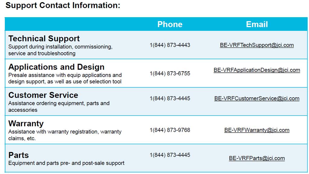
88 81
Thank you for selecting LENNOX air conditioners.
 S Models: LI012CI-180P432 LI012CO-180P432 LI012HI-180P432 LI012HO-180P432 LI024CI-180P432 LI024CO-180P432 LI024HI-180P432 LI024HO-180P432 (Refrigerant R410A) Thank you for selecting LENNOX air conditioners.
Change for Life. Service Manual
 Change for Life Service Manual Models: GWH09QB-K3DNA1G GWH09QB-K3DNA2G GWH09QB-K3DNA5G GWH09QB-K3DNB2G GWH09QB-K3DNB4G GWH09QB-K3DNB6G GWH12QC-K3DNA1G GWH12QC-K3DNA2G GWH12QC-K3DNA5G GWH12QC-K3DNB2G GWH12QC-K3DNB4G
DC INVERTER MULTI-SYSTEM AIR CONDITIONER
 TECHNICAL & SERVICE MANUAL OUTDOOR UNIT : CLM97 CLM7 CLM7 FILE NO. Destination: North America DC INVERTER MULTI-SYSTEM AIR CONDITIONER Capacity at 0V 9,700 BTU/h,00 BTU/h 0,600 BTU/h Outdoor Model No.
Submittal Sheet AIR-CON MULTI-SPLIT II. High-Wall Cassette Duct Floor and Ceiling AMTCM4H4R18
 Submittal Sheet Submitted for: Approval Record Job Name: Contractor: Engineer: Date: Location: Tag: AIR-CON MULTI-SPLIT II Indoor Units Outdoor Unit High-Wall Cassette Duct Floor and Ceiling AMTCM4H4R18
TECHNICAL DATA & SERVICE MANUAL
 TECHNICAL DATA & SERVICE MANUAL OUTDOOR UNIT: GRF188R5TAA GRF228R5TAA GRF228R7TAA SPLIT SYSTEM AIR CONDITIONER Model No. Product Code No. GRF188R5TAA 38.7107.083 GRF228R5TAA 38.7107.084 GRF228R7TAA 38.7107.085
Change for Life. Service Manual GREE ELECTRIC APPLIANCES,INC.OF ZHUHAI
 Change for Life Service Manual GREE ELECTRIC APPLIANCES,INC.OF ZHUHAI Table of Contents Part Ⅰ : Technical Information... 1 1. Summary... 1 2. Specifications... 4 2.1 Specifi cation Sheet... 4 2.2 Operation
Service Manual "X" SERIES 18K - 24K - 208/230V INVERTER-DRIVEN AIR CONDITIONING UNITS PLEASE READ AND UNDERSTAND THIS MANUAL BEFORE USING THIS
 "X" SERIES 18K - 24K - 208/230V IVERTER-DRIVE AIR CODITIOIG UITS Type Model IDOOR UIT DHX18WB21S DCX18WB21S DHX24WB21S DCX24WB21S Type Model OUTDOOR UIT DHX18CSB21S DCX18CSB21S DHX24CSB21S DCX24CSB21S
TECHNICAL DATA & SERVICE MANUAL SPLIT SYSTEM AIR CONDITIONER INDOOR UNIT: AW22AL AW28AL AW38AL AW42AL AW22AL AW28AL AW38AL
 TECHNICAL DATA & SERVICE MANUAL INDOOR UNIT: AW22AL AW28AL AW38AL AW42AL SPLIT SYSTEM AIR CONDITIONER Model No. Product Code No. AW22AL 387030005 AW28AL 387030006 AW38AL 387030007 AW42AL 387030094 0.8180.467.0
DC INVERTER MULTI-SYSTEM AIR CONDITIONER
 TECHNICAL & SERVICE MANUAL OUTDOOR UNIT : CU-3KE19NBU CU-4KE24NBU CU-4KE31NBU DC INVERTER MULTI-SYSTEM AIR CONDITIONER Capacity at 0V 19,100 BTU/h,200 BTU/h 30,600 BTU/h Outdoor Model No. CU-3KE19NBU CU-4KE24NBU
Installation Instructions
 40MBFQ Floor Console Ductless System Sizes 09 to 12 Installation Instructions TABLE OF CONTENTS PAGE SAFETY CONSIDERATIONS... 2 PARTS LIST... 3 SYSTEM REQUIREMENTS... 4 DIMENSIONS... 5 CLEARANCES... 5
TECHNICAL GUIDE MODELS: DCPM/DHPM PREMIUM SERIES DUCTLESS SINGLE-SPLIT AIR CONDITIONERS AND HEAT PUMPS 22 SEER 1 PHASE 3/4 THRU 3 NOMINAL TONS
 TECHNICAL GUIDE PREMIUM SERIES DUCTLESS SINGLE-SPLIT AIR CONDITIONERS AND HEAT PUMPS 22 SEER 1 PHASE 3/4 THRU 3 NOMINAL TONS MODELS: DCPM/DHPM Due to continuous product improvement, specifications are
TECHNICAL DATA & SERVICE MANUAL
 TECHNICAL DATA & SERVICE MANUAL OUTDOOR UNIT:. TRIAL SPLIT SYSTEM AIR CONDITIONER Model No. Product Code No. 38.7107.102. 0.8180.611.02 09/2012 IMPORTANT! Please read before installation This air conditioning
Service Manual. Models WAH48115MB WAH412230MB WH48YMB WH412ZMB
 Service Manual Models WAH48115MB WAH412230MB WH48YMB WH412ZMB TABLE OF CONTENT SPECIFICATION... 2 OUTLINE AND INSTALLATION DIMENSION... 4 REFRIGERATION SYSTEM DIAGRAM... 5 WIRING SCHEMATIC... 6 CONTROLS
SERVICE MANUAL. Split Air Conditioner Arctic Series mod. A
 EN SERVICE MANUAL Change for Life Split Air Conditioner Arctic Series mod. A9464915 MODELS: CH-S09FTXLA CH-S12FTXLA For proper operation, please read and keep this manual carefully. Designed by Cooper&Hunter
DC INVERTER SPLIT SYSTEM AIR CONDITIONER
 AIR CONDITIONER TECHNICAL & SERVICE MANUAL KS1872 + C1872 + CL1872 KS2472 + C2472 + CL2472 FILE NO. Destination: North America DC INVERTER SPLIT SYSTEM AIR CONDITIONER Indoor Model No. KS1872 KS2472 Product
Installation Instructions
 40MBFQ Floor Console Ductless System Sizes 09 to 58 Installation Instructions TABLE OF CONTENTS PAGE SAFETY CONSIDERATIONS... 2 PARTS LIST... 3 SYSTEM REQUIREMENTS... 4 WIRING... 4 DIMENSIONS... 5 CLEARANCES...
TECHNICAL DATA & SERVICE MANUAL
 TECHNICAL DATA & SERVICE MANUAL OUTDOOR UNIT: AE726SCL AE752SCL AE71SCL3 AE735SCL AE752SCL3 AE100SCL3 AE764SCL3 AE125SCL3 SPLIT SYSTEM AIR CONDITIONER Model No. AE726SCL AE735SCL AE752SCL AE752SCL3 AE764SCL3
INSTALLATION INSTRUCTIONS
 INSTALLATION INSTRUCTIONS - Wall-mount indoor unit - OPERATING LIMITS Cooling Maximum conditions Heating Maximum conditions Outdoor temperature : 122 F (50 C) D.B. Outdoor temperature : 75 F (24 C) D.B.
TECHNICAL DATA & SERVICE MANUAL
 TECHNICAL DATA & SERVICE MANUAL INDOOR UNIT: CAF97R5IAA CAF98MR5IAA CAF127R5IAA CAF128MR5IAA CAF187R5IAA SPLIT SYSTEM AIR CONDITIONER Model No. CAF97R5IAA CAF127R5IAA CAF187R5IAA CAF98MR5IAA CAF128MR5IAA
TECHNICAL DATA & SERVICE MANUAL SPLIT SYSTEM AIR CONDITIONER OUTDOOR UNIT: AE22AC/ACL/AH AE28AC/ACL/AH AE38AC/ACL/AH AE42AC/ACL/AH
 TECHNICAL DATA & SERVICE MANUAL OUTDOOR UNIT: AE22AC/ACL/AH AE28AC/ACL/AH AE38AC/ACL/AH AE42AC/ACL/AH SPLIT SYSTEM AIR CONDITIONER Model No. Product Code No. AE22AH 387031006 AE28AH 387031007 AE38AH 387031008
Installation Instructions
 40MAQ High Wall Ductless Split System Sizes 09 to 36 Installation Instructions NOTE: Read the entire instruction manual before starting the installation TABLE OF CONTENTS PAGE SAFETY CONSIDERATIONS 2 PARTS
Installation and Maintenance Manual
 Installation and Maintenance Manual INVERTER-DRIVEN MULTI-SPLIT SYSTEM HEAT PUMP AIR CONDITIONERS Type Ducted (Medium Static) with EconoFresh Kit Model (H,Y,C)IDM030B21E (H,Y,C)IDM036B21E (H,Y,C)IDM048B21E
AIR CONDITIONING SYSTEMS WALL MOUNTED UNIT
 AIR CONDITIONING SYSTEMS WALL MOUNTED UNIT SERVICE MANUAL MODELS: L4VI32-18/L4VO32-18 L4VI32-24/L4VO32-24 ENGLISH Table of Contents Part Ⅰ : Technical Information...1 1. Summary...1...2...3 2.2 Operation
Installation Instructions
 38MHR Outdoor Unit Single Zone Ductless System Sizes 09 to 24 Installation Instructions NOTE: Read the entire instruction manual before starting the installation. NOTE: Images are for illustration purposes
TECHNICAL DATA & SERVICE MANUAL
 TECHNICAL DATA & SERVICE MANUAL OUTDOOR UNIT: DUAL SPLIT SYSTEM AIR CONDITIONER Model No. Product Code No. 38.7107.098 38.7107.103 38.7107.106 0.8180.597.03 09/2012 IMPORTANT! Please read before installation
TECHNICAL DATA & SERVICE MANUAL
 TECHNICAL DATA & SERVICE MANUAL XH7R / CH7R, C7R XH7R / CH7R, C7R XH7R / CH7R, C7R TH7R / CH7R, C7R TH7R / CH7R, C7R TH7R / CH7R, C7R THH7R / CH7R THH7R / CH7R FILE NO. KH7R / CH7R, C7R KH07R / CH07R,
TABLE OF CONTENTS. NOTE: Read the entire instruction manual before starting the installation. TROUBLESHOOTING... 13
 R 410A Duct Free Split System Air Conditioner and Heat Pump Product Family: DFS4(A/H) System, DFC4(A/H)3 Outdoor, DFF4(A/H)H Indoor NOTE: Read the entire instruction manual before starting the installation.
DLCLRA. INSTALLATION INSTRUCTIONS Outdoor Unit Single Zone Ductless System Sizes 36 to 58 TABLE OF CONTENTS
 DLCLRA INSTALLATION INSTRUCTIONS Outdoor Unit Single Zone Ductless System Sizes 36 to 58 Fig. 1 - Size 36 TABLE OF CONTENTS PAGE SAFETY CONSIDERATIONS... 2 PARTS LIST... 3 SYSTEM REQUIREMENTS... 4 WIRING...
Installation and Maintenance Manual
 Installation and Maintenance Manual INVERTER-DRIVEN MULTI-SPLIT SYSTEM HEAT PUMP AIR CONDITIONERS Type Ducted (High Static) Ducted (Medium Static) Model (H,Y,C)IDH015B22S (H,Y,C)IDH018B22S (H,Y,C)IDH024B22S
AUTO COOL DRY FAN SPEED AIR SWING OFF ON TIMER TIMER OFF/ON FAN SPEED MODE TEMP AIR SWING TIMER ON SET OFF CANCEL AC RC SET CHECK CLOCK RESET
 AUTO COOL DRY MODE TIMER ON OFF TIMER OFF/ON TEMP ON TIMER FAN SPEED AIR SWING SET 1 2 3 FAN SPEED AIR SWING OFF CANCEL AC RC SET CHECK CLOCK RESET Order No: PAPAMY1611008CE Indoor Unit CS-MPS9SKH CS-MPS12SKH
OWNER S MANUAL DLFCAB / DLFCHB / DLFDAB / DLFDHB High Wall Ductless System Sizes 09 36
 OWNER S MANUAL DLFCAB / DLFCHB / DLFDAB / DLFDHB High Wall Ductless System Sizes 09 36 TABLE OF CONTENTS PAGE SAFETY PRECAUTIONS... 2 GENERAL... 2 INDOOR UNIT PART NAMES... 3 REMOTE CONTROL PART NAMES...
Service Manual. Model: ACZEM4C4R18/ACZCI4C4R18 ACZEM4H4R18/ACZCI4H4R18 ACZEM4C4R24/ACZCI4C4R24 ACZEM4H4R24/ACZCI4H4R24 (Refrigerant:R410A)
") Model: ACZEM4C4R18/ACZCI4C4R18 ACZEM4H4R18/ACZCI4H4R18 ACZEM4C4R24/ACZCI4C4R24 ACZEM4H4R24/ACZCI4H4R24 (Refrigerant:R410A) Table of Contents Part Ⅰ : Technical Information... 1 1. Summary... 1 2. Specifications...
Model: ACZEM4C4R18/ACZCI4C4R18 ACZEM4H4R18/ACZCI4H4R18 ACZEM4C4R24/ACZCI4C4R24 ACZEM4H4R24/ACZCI4H4R24 (Refrigerant:R410A) Table of Contents Part Ⅰ : Technical Information... 1 1. Summary... 1 2. Specifications...
ENGINEERING MANUAL INVERTER-DRIVEN MULTI-SPLIT SYSTEM HEAT PUMP AIR CONDITIONERS. Engineering Manual. Technical Catalog for Outdoor Unit
 ENGINEERING MANUAL INVERTER-DRIVEN MULTI-SPLIT SYSTEM HEAT PUMP AIR CONDITIONERS Technical Catalog for Outdoor Unit Engineering Manual < Indoor Units > Ducted (High Static) Type (H,Y)IDH072B21S (H,Y)IDH096B21S
SERVICE MANUAL. No. OBH747 REVISED EDITION-A. Models HFC
 Revision A: MUZ-HM09/12NA- U8, MUZ-HM09/12NA2- U8, MUZ-HM15/18NA- U1, MUZ-HM15/18NA2- U1 and MUZ-HM24NA2- U1 have been added. Please void OBH747. OUTDOOR INDOOR UNIT UNIT SERVICE MANUAL HFC utilized R410A.
GREE ELECTRIC APPLIANCES, INC. OF ZHUHAI
 Change for life Service Manual Models: GWH12QB-K6DNB8I GWH12QB-K6DNB2I GWH12QB-K6DNB4I GWH12QB-K6DNA1I GWH12QB-K6DND6I GWH12QB-K6DNA5I GWH12QB-K6DND6I GWH12QB-K6DNA3I GWH12QB-K6DNC6I GWH12QB-K6DNC4I GWH12QB-K6DNC8I
SERVICE MANUAL MUY-GL24NA - U1. No. OBH733. Models HFC. Revision B: REVISED EDITION-B R410A
 Revision B: MUZ-GL09NA- U8 and MUZ-GL09NAH- U8 have been added. Please void OBH733 REVISED EDITION-A. OUTDOOR INDOOR UNIT UNIT SERVICE MANUAL HFC utilized R410A. OBH733 REVISED EDITION-B Models MUZ-GL09NA
TECHNICAL DATA & SERVICE MANUAL SPLIT SYSTEM AIR CONDITIONER INDOOR UNIT: CAF94R5 CAF124R5 CAF94R
 TECHNICAL DATA & SERVICE MANUAL INDOOR UNIT: CAF94R5 CAF124R5 SPLIT SYSTEM AIR CONDITIONER Model No. Product Code No. CAF94R5 387106979 CAF124R5 387106980 0.8180.361.0 07/2005 IMPORTANT! Please read before
GWH09QB-K3DNC6D GWH12QB-K3DNA1D GWH12QB-K3DNA2D GWH12QB-K3DNA3D GWH12QB-K3DNA6D GWH12QB-K3DNB2D GWH12QB-K3DNB4D GWH12QB-K3DNB6D GWH12QB-K3DNB8D
 Change for Life Service Manual Models: GWH09QB-K3DNA1D GWH09QB-K3DNA2D GWH09QB-K3DNA3D GWH09QB-K3DNA5D GWH09QB-K3DNA6D GWH09QB-K3DNB2D GWH09QB-K3DNB4D GWH09QB-K3DNB6D GWH09QB-K3DNB8D GWH09QB-K3DNC2D GWH09QB-K3DNC4D
WMHP Series R410a Heat Pump INSTALLATION INSTRUCTIONS
 WMHP Series R410a Heat Pump INSTALLATION INSTRUCTIONS **WARNING TO INSTALLER, SERVICE PERSONNEL AND OWNER** Altering the product or replacing parts with non authorized factory parts voids all warranty
C&H NORDIC Commercial 4 SERVICE MANUAL
 C&H NORDIC Commercial 4 SERVICE MANUAL CONTENTS PRODUCT...3 1 MODELS LIST... 3 1.1 Outdoor Unit.... 3 1.2 Indoor Unit.... 4 2 PRODUCT DATA.... 5 2.1 Product Data of Indoor Unit... 5 2.2 Operation Range...
Service Manual. Models WAH418230MB WH418ZMB WAH424230MB WH424ZMB
 Service Manual Models WAH418230MB WH418ZMB WAH424230MB WH424ZMB TABLE OF CONTENT TABLE OF CONTENT... 1 SPECIFICATION... 1 OUTLINE AND INSTALLATION DIMENSION... 3 REFRIGERATION SYSTEM DIAGRAM... 6 WIRING
INSTALLATION INSTRUCTIONS Cased N Coil, Horizontal ENH4X
 INSTALLATION INSTRUCTIONS Cased N Coil, Horizontal ENH4X NOTE: Read the entire instruction manual before starting the installation. TABLE OF CONTENTS PAGE SAFETY CONSIDERATIONS... 1 INTRODUCTION... 1 INSTALLATION...
OWNER S MANUAL. R 410A Ductless Split System Air Conditioner and Heat Pump
 R 410A Ductless Split System Air Conditioner and Heat Pump Models DLC4(A/H) Outdoor Unit, DLF4(A/H) Indoor Unit Sizes 9K, 12K, 18K, 24K, 30K and 36K Please read the operating instructions and safety precautions
DESHUMIDIFIER MH-V5 Service manual
 DESHUMIDIFIER MH-V5 Service manual MH-10-V5 MH-20-V5 HU10530 to HU10531 English Table of Contents Part Ⅰ : Technical Information... 3 1.Summary... 3 2.Specifications... 4 3.Outline Dimension Diagram...
Installer manual AG-AA10. Air/air heat pump IHB GB AG-AA10-30 AG-AA10-40/50
 -30 Installer manual Air/air heat pump -40/50 IHB GB 1516-1 331554 Table of Contents 1 Important information 2 5 Installation 7 Safety information 2 Model combinations 7 Read before starting the installation
TECHNICAL & SERVICE MANUAL WINDOW TYPE AIR CONDITIONER SA 123A FILE NO. SA 123A REFERENCE NO. SM700513
 TECHNICAL & SERVICE MANUAL SA 123A FILE NO. WINDOW TYPE AIR CONDITIONER Model No. Product Code No. Destination SA-123A 1 851 006 95 Australia SA 123A REFERENCE NO. SM700513 IMPORTANT! Please Read Before
Installation Instructions
 38MPRA Outdoor Unit Single Zone Ductless System Sizes 09 to 12 Installation Instructions NOTES: Read the entire instruction manual before starting the installation. Images are for illustration purposes
SUBMITTAL M4MCW1509A-SUB-1B. Specifications 15 SERIES. Single Zone Mini-Split Inverter System M4MCW1509A1N0A M4TCS1509A11NA TAG:
 M4MCW1509A-SUB-1B TAG: 15 SERIES SUBMITTAL Specifications Single Zone Mini-Split Inverter System M4MCW1509A1N0A M4TCS1509A11NA MODEL - Cooling Only RATED Volts/PH Frequency (Hz) Rated Cooling Capacity
Installation Instructions
 40MBD Ducted Style Ductless System Sizes 09 to 48 Installation Instructions NOTE: Read the entire instruction manual before starting the installation. TABLE OF CONTENTS PAGE SAFETY CONSIDERATIONS... 2
SERVICE MANUAL OUTDOOR UNIT MUZ-FH06NAH MUZ-FH09NAH MUZ-FH06NA MUZ-FH09NA MUZ-FH09NA - 1 MUZ-FH09NAH - 1 MUZ-FH12NA MUZ-FH12NAH
 Revision D: Capacity corrections have been corrected [7-1. 2), 3)]. OBH684 REVISED EDITION-C is void. OUTDOOR UNIT SERVICE MANUAL HFC utilized R410A. OBH684 REVISED EDITION-D Models MUZ-FH06NA MUZ-FH09NA
Service Manual & Installation Manual
 GE Consumer & Industrial Appliances Service Manual & Installation Manual Split System Air Conditioner Model numbers: GE AIR C18 GE AIR C24 GE AIR C34 GE AIR C41 1 Introduction and Features Model Remarks
SERVICE MANUAL. Room Air Conditioner Split Wall-Mounted Type. Models:
 SERVICE MANUAL Room Air Conditioner Split Wall-Mounted Type Models: FSAI-PM-91BE2/ FSOAI-PM-91BE2 FSAI-PM-121BE2/ FSOAI-PM-121BE2 FSAI-PM-181BE2/ FSOAI-PM-181BE2 (Refrigerant:R410A) NOTE: Before servicing
INSTALLATION INSTRUCTIONS Cased N Coil, Horizontal ENH4X
 INSTALLATION INSTRUCTIONS Cased N Coil, Horizontal ENH4X NOTE: Read the entire instruction manual before starting the installation. TABLE OF CONTENTS PAGE SAFETY CONSIDERATIONS... 1 INTRODUCTION... 1 INSTALLATION...
TECHNICAL & SERVICE MANUAL WINDOW TYPE AIR CONDITIONER SA 183A FILE NO. SA 183A REFERENCE NO. SM Destination Australia SA-183A
 TECHNICAL & SERVICE MANUAL SA 183A FILE NO. WINDOW TYPE AIR CONDITIONER Model No. Product Code No. SA-183A 1 851 006 96 Destination Australia SA 183A REFERENCE NO. SM700514 IMPORTANT! Please Read Before
GREE ELECTRIC APPLIANCES, INC. OF ZHUHAI
 Change for life Models: GFH(09)EA-K6DNA1B/I GFH(12)EA-K6DNA1B/I GFH(18)EA-K6DNA1B/I GFH(21)EA-K6DNA1B/I Models: GFH(24)EA-K6DNA1B/I (Refrigerant R32) GREE ELECTRIC APPLIANCES, INC. OF ZHUHAI Table of Contents
General safety precautions English
 English A min (m 2 ) 550 530 540 510 520 490 500 470 480 450 460 430 440 410 420 390 400 370 380 350 360 330 340 310 320 290 300 270 280 250 260 230 240 210 220 190 200 170 180 150 160 130 140 110 120
General safety precautions English
 English A min (m 2 ) 550 530 540 510 520 490 500 470 480 450 460 430 440 410 420 390 400 370 380 350 360 330 340 310 320 290 300 270 280 250 260 230 240 210 220 190 200 170 180 150 160 130 140 110 120
Model No. GB-PAC-08E4. 8,000 BTU Portable Air Conditioner Operating Instructions
 Model No. GB-PAC-08E4 8,000 BTU Portable Air Conditioner Operating Instructions Thank you for choosing a Soleus Air Powered by Gree Portable Air Conditioner. This owner s manual will provide you with valuable
INSTALLATION INSTRUCTIONS Cased N Coil, Horizontal ENH4X
 INSTALLATION INSTRUCTIONS Cased N, Horizontal ENH4X NOTE: Read the entire instruction manual before starting the installation. SAFETY CONSIDERATIONS Improper installation, adjustment, alteration, service,
Operating Instructions Air Conditioner
 F566113 Operating Instructions Air Conditioner Indoor Unit CS-E18HKR CS-E1HKR CS-E4HKR CS-E8HKR Outdoor Unit CU-E18HKR CU-E1HKR CU-E4HKR CU-E8HKR Before operating the unit, read these operating instructions
Installation Instructions
 40MAQ / 38MAQ 619PB / 538PR High---Wall Ductless Split System Sizes 09 to 30 Installation Instructions TABLE OF CONTENTS PAGE PARTS LIST... 2 SAFETY CONSIDERATIONS... 3 SYSTEM REQUIREMENTS... 4 DIMENSIONS...
Installation Instructions
 8GXM / 0GXM Multi---Split High---Wall Duct Free Split System 8GXM --- Size 18k, k, and 0k 0GXM --- Size 9k, 1k, and 18k Installation Instructions NOTE: Read the entire instruction manual before starting
Portable Air Conditioner with Heat Pump Technology Operating Instructions. Model No.: HCB-P13HP-D. Reference No.: BPD13HP V140217
 Portable Air Conditioner with Heat Pump Technology Operating Instructions 3092402 Model No.: HCB-P13HP-D Reference No.: BPD13HP V140217 Thank you for choosing a Soleus Air Portable Air Conditioner with
0RGHOV,QGRRU 8QLW MWM36Y3J 2XWGRRU 8QLW MRM36Y3J 11
 MWM36Y3J MRM36Y3J 11 Content Operation Notices Precautions...1 Parts name...2 Screen Operation Guide Buttons on remote controller...3 Introduction for icons on display screen...3 Introduction for buttons
DLCSRA. INSTALLATION INSTRUCTIONS Outdoor Unit Ductless Split System Sizes 09 to 36 TABLE OF CONTENTS
 DLCSRA INSTALLATION INSTRUCTIONS Outdoor Unit Ductless Split System Sizes 09 to 36 NOTES: Read the entire instruction manual before starting the installation. Images are for illustration purposes only.
TECHNICAL DATA & SERVICE MANUAL SPLIT SYSTEM AIR CONDITIONER INDOOR UNIT: ASR609CL ASR612CL ASR609CL ASR612CL
 TECHNICAL DATA & SERVICE MANUAL INDOOR UNIT: ASR609CL ASR612CL SPLIT SYSTEM AIR CONDITIONER Model No. Product Code No. ASR609CL 387006970 ASR612CL 387006971 0.8180.250.0 05/2002 IMPORTANT! Please read
Installation Instructions
 CNPHP Cased N Coils Horizontal Heating --- Cooling NOTE: Read the entire instruction manual before starting the installation. TABLE OF CONTENTS PAGE SAFETY CONSIDERATIONS... 1 INTRODUCTION... 1 INSTALLATION...
Change for Life. Service Manual. Models: CH-S24FTXE Wi-Fi (Refrigerant R410A)
") Change for Life Service Manual Models: CH-S24FTXE Wi-Fi (Refrigerant R410A) Table of Contents Part Ⅰ : Technical Information...1 1. Summary...1 2. Specifications...2 2.1 Specification Sheet...2 2.2 Operation
Change for Life Service Manual Models: CH-S24FTXE Wi-Fi (Refrigerant R410A) Table of Contents Part Ⅰ : Technical Information...1 1. Summary...1 2. Specifications...2 2.1 Specification Sheet...2 2.2 Operation
Chiltrix 5.1 Thin DC - Inverter Water Fan Coil Unit Floor, Wall or Ceiling Universal Mount Manual
 Chiltrix 5.1 Thin DC - Inverter Water Fan Coil Unit Floor, Wall or Ceiling Universal Mount Manual Version 1.5 1 CONTENTS CHAPTER 1 GENERAL INTRODUCTION...3 1. Preface... 3 2. Product Introduction... 3
Part Ⅰ : Technical Information
 Part Ⅰ : Technical Information 1. Summary Outdoor Unit GWHD(6)KJO GWHD(4)KJO Technical Information 1 . Specifications Model GWHD(6)KJO GWHD(4)KJO Product Code C860W0190 C860W000 Rated Voltage V~ 0-40 0-40
VMI-1102-A SERVICE MANUAL AIRCONDITIONER DC INVERTER MULTI TYPE MSV1I-09HRDN1-M TAS-09MVHN TAS-12MVHN INDOOR VERTU DC INVERTER MULTI SERIES
 VMI-1102-A SERVICE MANUAL AIRCONDITIONER DC INVERTER MULTI TYPE MSV1I-09HRDN1-M TAS-09MVHN TAS-12MVHN INDOOR VERTU DC INVERTER MULTI SERIES CONTENTS 1. Precaution... 1 1.1 Safety Precaution...1 1.2 Warning...1
INSTALLATION MANUAL COMFORT...BUILT TO LAST. 9,000, 12,000 and 18,000 BTU SINGLE-ZONE DUCTLESS MINI-SPLIT SYSTEM Heat Pump
 COMFORT...BUILT TO LAST 9,000, 12,000 and 18,000 BTU SINGLE-ZONE DUCTLESS MINI-SPLIT SYSTEM Heat Pump INSTALLATION MANUAL INDOOR UNIT: 1PAMSH09-SZW-14.5 1PAMSH09-SZW-15 1PAMSH12-SZW-15 1PAMSH18-SZW-15
Operating Instructions Air Conditioner
 F56579 Operating Instructions Air Conditioner Indoor Unit Outdoor Unit CS-E18GKR CS-E1GKR CS-E4GKR CS-E8GKR CU-E18GKR CU-E1GKR CU-E4GKR CU-E8GKR Before operating the unit, read these operating instructions
Installation Instructions
 CNPHP Cased N s Horizontal Heating --- Cooling Installation Instructions NOTE: Read the entire instruction manual before starting the installation. TABLE OF CONTENTS PAGE SAFETY CONSIDERATIONS... 1 INTRODUCTION...
Installation Instructions
 40MAQ High Wall Ductless System Sizes 09 to 36 Installation Instructions NOTES: Read the entire instruction manual before starting the installation. Images are for illustration purposes only. Actual models
PORTABLE AIR CONDITIONER
 OWNER S MANUAL PORTABLE AIR CONDITIONER Model: CH-M09K6S F or proper operation, please read and keep this manual carefully. Designed by Cooper&Hunter International Corporation, Oregon, USA www.cooperandhunter.com
14,000 BTU Portable Air Conditioner 14,200 BTU Heat Pump Model Number: LX-140 Operating Instructions. Model No. LX Soleus Air International
 14,000 BTU Portable Air Conditioner 14,200 BTU Heat Pump Model Number: LX-140 Operating Instructions 3092402 Model No. LX-140 2012 Soleus Air International Thank you for choosing a Soleus Air LX-140 Portable
SUBMITTAL M4MHW1509A-SUB-1B. Specifications 15 SERIES. Single Zone Mini-Split Inverter System M4MHW1509A1N0A M4THS1509A11NA TAG:
 M4MHW1509A-SUB-1B TAG: 15 SERIES SUBMITTAL Specifications Single Zone Mini-Split Inverter System M4MHW1509A1N0A M4THS1509A11NA 2017 Ingersoll Rand All Rights Reserved MODEL - Heat Pump Only RATED Volts/PH
Utopian Split A/C. Thank you for purchasing this quality Split A/C system!
 Utopian Split A/C Thank you for purchasing this quality Split A/C system! Please read through this manual completely, and keep it in case you need to reference the information in the future. Any operation
SUBMITTAL M4MCW1509A-SUB-1C. Specifications 15 SERIES. Single Zone Mini-Split Inverter System M4MCW1509A1N0A M4TCS1509A11NA TAG:
 M4MCW1509A-SUB-1C TAG: 15 SERIES SUBMITTAL Specifications Single Zone Mini-Split Inverter System M4MCW1509A1N0A M4TCS1509A11NA MODEL - Cooling Only RATED Volts/PH Frequency (Hz) Rated Cooling Capacity
Split Air Conditioner. Model: WMI09MH16S WMI12MH16S WMI18MH16S
 Split Air Conditioner Model: WMI09MH16S WMI12MH16S WMI18MH16S Thank you for choosing our product. For proper operation, please read and keep this manual carefully. Content Operation Notices Precautions...1
WIRING DIAGRAM. This manual describes the unit features and explains how to set-up, operate and maintain these AirPac Models. COOLIT2600 COOLIT2900
 WIRING DIAGRAM This manual describes the unit features and explains how to set-up, operate and maintain these AirPac Models. COOLIT2600 COOLIT2900 17 THANK YOU! WARRANTY INFORMATION Thank you for choosing
NON-CYCLING REFRIGERATED AIR/GAS DRYERS QPNC 75 to QPNC 250 OPERATOR S MANUAL
 NON-CYCLING REFRIGERATED AIR/GAS DRYERS QPNC 75 to QPNC 250 OPERATOR S MANUAL DATE OF PURCHASE: MODEL: SERIAL NO.: Record above information from nameplate. Retain this information for future reference.
Owner s Manual Super-Slim Four-Way Cassette
 CASSETTE- TYPE AIR CONDITIONER Owner s Manual Super-Slim Four-Way Cassette IMPORTANT NOTE: Read this manual carefully before installing or operating your new air conditioning unit. Make sure to save this
CASSETTE, FLOOR&CEILING, DUCT UNITS OUTDOOR UNITS
 SERVICE MANUAL MULTI COMBI OUTDOOR AND INDOOR UNITS CASSETTE, FLOOR&CEILING, DUCT UNITS OUTDOOR UNITS (36k,42k) COMBINATION TABLE (unit: kw) MC-E18AI MC-E24AI MC-E28AI MC-E36AI 1 model 2 models 2 models
CR13000-PAC OWNER S MANUAL. Portable Air Conditioner. PORTABLE AIR CONDITIONER with HEAT PUMP. Operating and Servicing Instructions
 OWNER S MANUAL Operating and Servicing Instructions CR13000-PAC PORTABLE AIR CONDITIONER with HEAT PUMP Portable Air Conditioner Questions or concerns? For assistance, please call Customer Service ClimateRight
Ductless Split Air Conditioner
 Ductless Split Air Conditioner Service Manual Indoor HSU09VHG(DB)-W HSUVHG(DB)-W HSU8VHH(DB)-W HSUVHG(DB)-W Outdoor HSU09VHG(DB)-G HSUVHG(DB)-G HSU8VHH(DB)-G HSUVHG(DB)-G Design may vary by model number.
KSD-35 DR11 KUE-35 DVN11
 FLOOR-STANDING TYPE AIR CONDITIONER Owner s Manual Floor-Standing Type KSD-35 DR11 KUE-35 DVN11 IMPORTANT NOTE: Read this manual carefully before installing or operating your new air conditioning unit.
Service Manual & Installation Manual
 GE Consumer & Industrial Appliances Service Manual & Installation Manual Split System Air Conditioner Model numbers: GE AIR F24 GE AIR F34 GE AIR F41 1 2 3 Introduction and Features Model Remarks GE AIR
TECHNICAL GUIDE MODELS: DCMF/DHMF LX SERIES DUCTLESS SINGLE-SPLIT AIR CONDITIONERS AND HEAT PUMPS 16 SEER 1 PHASE 3/4 THRU 2 NOMINAL TONS DESCRIPTION
 TECHNICAL GUIDE LX SERIES DUCTLESS SINGLE-SPLIT AIR CONDITIONERS AND HEAT PUMPS 16 SEER 1 PHASE 3/4 THRU 2 NOMINAL TONS MODELS: DCMF/DHMF Due to continuous product improvement, specifications are subject
SUBMITTAL M4MLW1809A-SUB-1A. Specifications 18 SERIES. Single Zone Mini-Split Inverter System M4MLW1809A1N0A M4TLS1809A11NA TAG:
 M4MLW1809A-SUB-1A TAG: 18 SERIES SUBMITTAL Specifications Single Zone Mini-Split Inverter System M4MLW1809A1N0A M4TLS1809A11NA MODEL - Heat Pump Only RATED Volts/PH Frequency (Hz) Rated Cooling / Heating
General safety precautions English
 English 1 1 1.1 About the documentation The original documentation is written in English. All other languages are translations. The precautions described in this document cover very important topics, follow
YC ON-OFF SERIES. Service Manual
 YC ON-OFF SERIES Service Manual CONTENTS 1. Precaution... 3 1.1 Safety Precaution... 3 1.2 Warning... 3 2. Model Lists... 6 3. Dimension... 7 3.1 Indoor Unit... 7 3.2 Outdoor Unit... 11 4. Refrigerant
for Light Commercial Use
 Inverter Air Conditioning for Light Commercial Use 4 Toshiba's unique energy-efficient air conditioning innovations and technologies deliver high energy savings. Aluminum heat exchanger * High heat exchanger
HEAT PUMP INSTALLATION MANUAL
 DUCTLESS INVERTER HEAT PUMP INSTALLATION MANUAL Models: TERRA09HP230V1A TERRA12HP230V1A TERRA18HP230V1B TERRA24HP230V1B Thank you for choosing a Gree Terra Ductless Heat Pump for your customer. Please
Operating Instructions Air Conditioner
 alleru-buster F566894 Operating Instructions Air Conditioner Indoor Unit CS-RE9JKR CS-RE1JKR Outdoor Unit CU-RE9JKR CU-RE1JKR ENGLISH ~ 7 Before operating the unit, read these operating instructions thoroughly
General safety precautions English
 English 1 1 Units are marked with the following symbol: 1.1 About the documentation The original documentation is written in English. All other languages are translations. The precautions described in
Owner s Manual. Middle Static Pressure Duct Type MEU-18MPH2 MEU-24MPH2 MEU-36MPL2 MEU-48MPL2 MIDDLE STATIC PRESSURE DUCT TYPE AIR CONDITIONER
 MIDDLE STATIC PRESSURE DUCT TYPE AIR CONDITIONER Owner s Manual Middle Static Pressure Duct Type MEU-18MPH2 MEU-24MPH2 MEU-36MPL2 MEU-48MPL2 IMPORTANT NOTE: Read this manual carefully before installing
Portable Air Conditioner with Heat Pump Technology PH4-10R-01, PH4-12R-01, & PH4-14R-01 Operating Instructions
 Portable Air Conditioner with Heat Pump Technology PH4-10R-01, PH4-12R-01, & PH4-14R-01 Operating Instructions 3092402 2006 Soleus Air International Thank you for choosing a Soleus Air Portable Air Conditioner
13500 BTU RV Air Conditioner Installation and Operating Instructions
 13500 BTU RV Air Conditioner Installation and Operating Instructions Model No.:HCB-R135-A-ID HCB-R135-A-OD 3092402 V140804 Thank you for choosing a Soleus Air RV Air Conditioner. This owner s manual will