GWH09QB-K3DNC6D GWH12QB-K3DNA1D GWH12QB-K3DNA2D GWH12QB-K3DNA3D GWH12QB-K3DNA6D GWH12QB-K3DNB2D GWH12QB-K3DNB4D GWH12QB-K3DNB6D GWH12QB-K3DNB8D
|
|
|
- Pierce Potter
- 6 years ago
- Views:
Transcription


1 Change for Life Service Manual Models: GWH09QB-K3DNA1D GWH09QB-K3DNA2D GWH09QB-K3DNA3D GWH09QB-K3DNA5D GWH09QB-K3DNA6D GWH09QB-K3DNB2D GWH09QB-K3DNB4D GWH09QB-K3DNB6D GWH09QB-K3DNB8D GWH09QB-K3DNC2D GWH09QB-K3DNC4D GWH09QB-K3DNC6D GWH12QB-K3DNA1D GWH12QB-K3DNA2D GWH12QB-K3DNA3D GWH12QB-K3DNA6D GWH12QB-K3DNB2D GWH12QB-K3DNB4D GWH12QB-K3DNB6D GWH12QB-K3DNB8D GWH12QB-K3DNC2D GWH12QB-K3DNC4D GWH12QB-K3DNC6D (Refrigerant:R410A) GREE ELECTRIC APPLIANCES,INC.OF ZHUHAI
2 Table of Contents Part Ⅰ : Technical Information Summary Specifications Specification Sheet Operation Characteristic Curve Capacity Variation Ratio According to Temperature Cooling and Heating Data Sheet in Rated Frequency Noise Curve Outline Dimension Diagram Indoor Unit Outdoor Unit Refrigerant System Diagram Electrical Part Wiring Diagram PCB Printed Diagram Function and Control Remote Controller Introduction Brief Description of Modes and Functions...20 Part Ⅱ : Notes for Installation Installation Dimension Diagram Installation Parts-checking Selection of Installation Location Electric Connection Requirement Installation of Indoor Unit Installation of Outdoor Unit Vacuum Pumping and Leak Detection Check after Installation and Test Operation...33 Table of Contents
3 9. Maintenance Malfunction Analysis Flashing LED of Indoor/Outdoor Unit and Primary Judgement How to Check Simply the Main Part Exploded View and Parts List Indoor Unit Outdoor Unit Removal Procedure Removal Procedure of Indoor Unit Removal Procedure of Outdoor Unit...89 Appendix:...98 Appendix 1: Reference Sheet of Celsius and Fahrenheit...98 Appendix 2: Configuration of Connection Pipe...98 Appendix 3: Pipe Expanding Method...99 Appendix 4: List of Resistance for Temperature Sensor Table of Contents
4 Part Ⅰ : Technical Information 1. Summary Indoor Unit: A1 Panel A2 Panel A3 Panel A5 Panel A6 Panel B2 Panel B4 Panel B6 Panel B8 Panel C2 Panel Technical Information 1
5 Service Manual C4 Panel C6 Panel Outdoor Unit: GWH09QB-K3DNA6D/O GWH12QB-K3DNA6D/O Remote Controller: YX1F T-ON T-OFF AUTO COOL DRY FAN HEAT ON/OFF 2 SWING SLEEP LOCK SPEED MODE - + FAN SWING SLEEP TIMER Technical Information
6 2. Specifications 2.1 Specification Sheet Model Product Code Power Supply 1.GWH09QB-K3DNA1D 2.GWH09QB-K3DNA2D 3.GWH09QB-K3DNA3D 4.GWH09QB-K3DNA5D 5.GWH09QB-K3DNA6D 6.GWH09QB-K3DNB2D 7.GWH09QB-K3DNB4D 8.GWH09QB-K3DNB6D 9.GWH09QB-K3DNB8D 10.GWH09QB-K3DNC2D 11.GWH09QB-K3DNC4D 12.GWH09QB-K3DNC6D 1.CB /CB CB CB /CB CB CB /CB CB /CB CB /CB CB CB /CB CB CB /CB CB Rated Voltage V~ Rated Frequency Hz 50 Phases 1 Outdoor Power Supply Mode Cooling Capacity(Min~Max) W 2500 (600~2800) Heating Capacity(Min~Max) W 2800 (600~3200) Cooling Power Input(Min~Max) W 780 (120~1300) Heating Power Input(Min~Max) W 775 (120~1400) Cooling Current Input A 3.60 Heating Current Input A 3.50 Rated Input W 1400 Rated Current A 6.70 Air Flow Volume(SH/H/M/L/SL) m 3 /h 480/370/320/210/- Dehumidifying Volume L/h 1 EER W/W 3.21 COP W/W 3.61 SEER 6.10 SCOP(Average/Warmer/Colder) 4.00/5.10/3.30 HSPF / Application Area m Indoor Unit 1.GWH09QB-K3DNA1D/I 2.GWH09QB-K3DNA2D/I 3.GWH09QB-K3DNA3D/I Indoor Unit Model 4.GWH09QB-K3DNA5D/I 5.GWH09QB-K3DNA6D/I 6.GWH09QB-K3DNB2D/I 7.GWH09QB-K3DNB4D/I 8.GWH09QB-K3DNB6D/I 9.GWH09QB-K3DNB8D/I 10.GWH09QB-K3DNC2D/I 11.GWH09QB-K3DNC4D/I 12.GWH09QB-K3DNC6D/I 1.CB419N08700/CB419N CB426N CB424N03300/ CB424N CB425N CB427N04800/CB427N04801 Indoor Unit Product Code 6.CB432N05700/CB432N CB434N04500/CB434N CB435N CB438N03000/CB438N CB439N CB444N01600/CB444N CB443N00700 Fan Type Cross-flow Fan Diameter Length(DXL) mm Ф98X580 Cooling Speed(SH/H/M/L/SL) r/min 1300/1200/1050/800/- Heating Speed(SH/H/M/L/SL) r/min 1300/1200/1050/900/- Fan Motor Power Output W 20 Fan Motor RLA A Fan Motor Capacitor μf 1 Evaporator Form Aluminum Fin-copper Tube Evaporator Pipe Diameter mm Ф5 Evaporator Row-fin Gap mm Evaporator Coil Length(LXDXW) mm 584X22.8X266.7 Swing Motor Model MP24AA Swing Motor Power Output W 1.5 Fuse Current A 3.15 Sound Pressure Level(SH/H/M/L/SL) db (A) 40/36/34/29/- Sound Power Level(SH/H/M/L/SL) db (A) 50/47/44/39/- Dimension(WXHXD) mm 790X275X200 Dimension of Carton Box(LXWXH) mm 850X339X262 Dimension of Package(LXWXH) mm 852X355X273 Net Weight kg 9 Gross Weight kg 11 Technical Information 3
7 Outdoor Unit Model of Outdoor Unit Product Code of Outdoor Unit Compressor Manufacturer/Trademark Compressor Model Compressor Oil Compressor Type GWH09QB-K3DNA6D/O CB427W04800 ZHUHAI LANDA COMPRESSOR CO., LTD QXA-A091zE190A 68EP Rotary L.R.A. A 17 Compressor RLA A 5 Compressor Power Input W 942 Overload Protector Throttling Method Operation temp Ambient temp (cooling) Ambient temp (heating) Condenser Form 1NT11L-6233 Capillary o C 16~30 o C -15~48 o C -22~24 Aluminum Fin-copper Tube Pipe Diameter mm Ф7 Rows-fin Gap mm Coil Length (LXDXW) mm 710X19.05X506 Fan Motor Speed rpm 900 Output of Fan Motor W 30 Fan Motor RLA A 0.4 Fan Motor Capacitor μf / Air Flow Volume of Outdoor Unit m 3 /h 1600 Fan Type Axial-flow Fan Diameter mm Ф400 Defrosting Method Climate Type Isolation Moisture Protection Automatic Defrosting T1 I IPX4 Permissible Excessive Operating Pressure for the Discharge Side MPa 4.3 Permissible Excessive Operating Pressure for the Suction Side MPa 2.5 Sound Pressure Level (H/M/L) db (A) 51/-/- Sound Power Level (H/M/L) db (A) 60/-/- Dimension (WXHXD) mm 776X540X320 Dimension of Carton Box (LXWXH) mm 820X355X580 Dimension of Package (LXWXH) mm 823X358X595 Net Weight kg 25.5 Gross Weight kg 28 Refrigerant R410A Refrigerant Charge kg 0.7 Length m 5 Gas Additional Charge g/m 20 Outer Diameter Liquid Pipe mm Ф6 Connection Outer Diameter Gas Pipe mm Ф9.52 Pipe Max Distance Height m 10 Max Distance Length m 15 Note: The connection pipe applies metric diameter. The above data is subject to change without notice; please refer to the nameplate of the unit. 4 Technical Information
8 Model Product Code Power Supply 1.GWH12QB-K3DNA1D 2.GWH12QB-K3DNA2D 3.GWH12QB-K3DNA3D 4.GWH12QB-K3DNA5D 5.GWH12QB-K3DNA6D 6.GWH12QB-K3DNB2D 7.GWH12QB-K3DNB4D 8.GWH12QB-K3DNB6D 9.GWH12QB-K3DNB8D 10.GWH12QB-K3DNC2D 11.GWH12QB-K3DNC4D 12.GWH12QB-K3DNC6D 1.CB /CB CB CB /CB CB CB /CB CB /CB CB /CB CB CB /CB CB CB /CB CB Rated Voltage V~ Rated Frequency Hz 50 Phases 1 Outdoor Power Supply Mode Cooling Capacity(Min~Max) W 3200 (600~3600) Heating Capacity(Min~Max) W 3400 (600~3800) Cooling Power Input(Min~Max) W 997 (120~1400) Heating Power Input(Min~Max) W 942 (120~1500) Cooling Current Input A 4.50 Heating Current Input A 4.4 Rated Input W 1500 Rated Current A 7.2 Air Flow Volume(SH/H/M/L/SL) m 3 /h 560/480/410/290/- Dehumidifying Volume L/h 1 EER W/W 3.21 COP W/W 3.61 SEER 6.10 SCOP(Average/Warmer/Colder) 4.00/5.10/3.30 HSPF / Application Area m GWH12QB-K3DNA1D/I 2.GWH12QB-K3DNA2D/I 3.GWH12QB-K3DNA3D/I Indoor Unit Model 4.GWH12QB-K3DNA5D/I 5.GWH12QB-K3DNA6D/I 6.GWH12QB-K3DNB2D/I 7.GWH12QB-K3DNB4D/I 8.GWH12QB-K3DNB6D/I 9.GWH12QB-K3DNB8D/I 10.GWH12QB-K3DNC2D/I 11.GWH12QB-K3DNC4D/I 12.GWH12QB-K3DNC6D/I 1.CB419N08800/CB419N CB426N CB424N03400/CB424N03401 Indoor Unit Product Code 4.CB425N CB427N04700/CB427N CB432N05200/CB432N CB434N04400/CB434N CB435N CB438N03200/CB438N CB439N CB444N01500/CB444N CB443N00900 Fan Type Cross-flow Indoor Unit Fan Diameter Length(DXL) mm Ф98X580 Cooling Speed(SH/H/M/L/SL) r/min 1350/1200/1050/750/- Heating Speed(SH/H/M/L/SL) r/min 1350/1200/1050/850/- Fan Motor Power Output W 20 Fan Motor RLA A Fan Motor Capacitor μf 1 Evaporator Form Aluminum Fin-copper Tube Evaporator Pipe Diameter mm Ф5 Evaporator Row-fin Gap mm Evaporator Coil Length(LXDXW) mm 584X22.8X266.7 Swing Motor Model MP24AA Swing Motor Power Output W 1.5 Fuse Current A 3.15 Sound Pressure Level(SH/H/M/L/SL) db (A) 42/39/33/28/- Sound Power Level(SH/H/M/L/SL) db (A) 55/49/43/38/- Dimension(WXHXD) mm 790X275X200 Dimension of Carton Box(LXWXH) mm 850X339X262 Dimension of Package(LXWXH) mm 852X355X273 Net Weight kg 9 Gross Weight kg 11 Technical Information 5
9 Outdoor Unit Model of Outdoor Unit Product Code of Outdoor Unit Compressor Manufacturer/Trademark Compressor Model Compressor Oil Compressor Type GWH12QB-K3DNA6D/O CB427W04700 ZHUHAI LANDA COMPRESSOR CO., LTD QXA-B102zE190 RB68EP Rotary L.R.A. A 35 Compressor RLA A 4.80 Compressor Power Input W 1020 Overload Protector / Throttling Method Operation temp Ambient temp (cooling) Ambient temp (heating) Condenser Form Capillary o C 16~30 o C -15~48 o C -22~24 Aluminum Fin-copper Tube Pipe Diameter mm Ф7.94 Rows-fin Gap mm Coil Length (LXDXW) mm 731X19.05X550 Fan Motor Speed rpm 900 Output of Fan Motor W 30 Fan Motor RLA A 0.4 Fan Motor Capacitor μf / Air Flow Volume of Outdoor Unit m 3 /h 2200 Fan Type Axial-flow Fan Diameter mm Ф438 Defrosting Method Climate Type Isolation Moisture Protection Automatic Defrosting T1 I IPX4 Permissible Excessive Operating Pressure for the Discharge Side MPa 4.3 Permissible Excessive Operating Pressure for the Suction Side MPa 2.5 Sound Pressure Level (H/M/L) db (A) 52/-/- Sound Power Level (H/M/L) db (A) 62/-/- Dimension (WXHXD) mm 842X596X320 Dimension of Carton Box (LXWXH) mm 878X360X630 Dimension of Package (LXWXH) mm 881X363X645 Net Weight kg 29.5 Gross Weight kg 32.5 Refrigerant R410A Refrigerant Charge kg 0.9 Length m 5 Gas Additional Charge g/m 20 Outer Diameter Liquid Pipe mm Ф6 Connection Outer Diameter Gas Pipe mm Ф9.52 Pipe Max Distance Height m 10 Max Distance Length m 20 Note: The connection pipe applies metric diameter. The above data is subject to change without notice; please refer to the nameplate of the unit. 6 Technical Information
10 2.2 Operation Characteristic Curve Cooling Heating Current (A) Conditions 220V V 9 Indoor:DB27 C/WB19 C 9 8 Outdoor:DB35 C/WB24 C 8 Indoor air flow:super High 7 Pipe length:5m 7 230V V 5 240V 4 4 Conditions 3 3 Indoor:DB20 C/WB15 C 2 240V 2 Outdoor:DB7 C/WB6 C Indoor air flow:super High 1 1 Pipe length:5m Compressor speed (rps) Compressor speed (rps) Current (A) Capacity Variation Ratio According to Temperature Cooling Heating 105 Capacity ratio (%) Conditions Indoor:DB27 C/WB19 C 60 Indoor air flow:super High 55 Pipe length: 5m Capacity ratio(%) Conditions Indoor:DB20 C/WB15 C Indoor air flow:super High Pipe length: 5m Outdoor temp.( C) Outdoor temp.( o C) Technical Information 7
11 2.4 Cooling and Heating Data Sheet in Rated Frequency Cooling: Rated cooling condition( o C) (DB/WB) Heating: Model Instruction: T1: Inlet and outlet pipe temperature of evaporator T2: Inlet and outlet pipe temperature of condenser P: Pressure at the side of big valve Connection pipe length: 5 m. Pressure of gas pipe connecting indoor and outdoor unit Inlet and outlet pipe temperature of heat exchanger Indoor Outdoor P (MPa) T1 ( o C) T2 ( o C) 27/19 35/24 Rated heating condition( o C) (DB/WB) Fan speed of indoor unit Fan speed of outdoor unit Compressor frequency (Hz) 09K ~ to to 41 Super High High 12K 72 Model Pressure of gas pipe connecting indoor and outdoor unit Inlet and outlet pipe temperature of heat exchanger Indoor Outdoor P (MPa) T1 ( C) T2 ( C) 20/15 7/6 Fan speed of indoor unit Fan speed of outdoor unit Compressor frequency (Hz) 09K ~ to 41 2 to 5 Super High High 12K Noise Curve 70 Outdoor side noise 50 Indoor side noise 60 Noise/dB(A) Noise/dB(A) Low Middle High Supper High Indoor fan motor rotating speed Compressor frequency/hz 09K 12K 18K 8 Technical Information
12 3. Outline Dimension Diagram 3.1 Indoor Unit W D H Φ55 Φ Models W H D 09/12K Unit:mm Technical Information 9
13 Service Manual 3.2 Outdoor Unit K Unit:mm K Unit:mm 10 Technical Information
14 4. Refrigerant System Diagram Cooling and heating model Indoor unit Outdoor unit Gas pipe side Valve 4-Way valve Discharge Heat exchanger (evaporator) Liquid pipe side Valve Suction Accumlator Compressor Strainer Capillary Strainer Heat exchanger (condenser) COOLING HEATING Connection pipe specification: Liquid pipe:1/4" (6mm) Gas pipe:3/8" (9.52mm) Technical Information 11
15 5. Electrical Part 5.1 Wiring Diagram Instruction Symbol Symbol Color Symbol Symbol Color Symbol Name WH White GN Green CAP Jumper cap YE Yellow BN Brown COMP Compressor RD Red BU Blue Grounding wire YEGN Yellow/Green BK Black / / VT Violet OG Orange / / Note: Jumper cap is used to determine fan speed and the swing angle of horizontal lover for this model. Indoor Unit GWH09QB-K3DNA1D/I(CB419N08700) GWH09QB-K3DNA3D/I(CB424N03300) GWH09QB-K3DNA6D/I(CB427N04800) GWH09QB-K3DNB2D/I(CB432N05700) GWH09QB-K3DNB4D/I(CB434N04500) GWH09QB-K3DNB8D/I(CB438N03001) GWH09QB-K3DNC4D/I(CB444N01600) GWH12QB-K3DNA1D/I(CB419N08800) GWH12QB-K3DNA3D/I(CB424N03400) GWH12QB-K3DNA6D/I(CB427N04700) GWH12QB-K3DNB2D/I(CB432N05200) GWH12QB-K3DNB4D/I(CB434N04400) GWH12QB-K3DNB8D/I(CB438N03201) GWH12QB-K3DNC4D/I(CB444N01500) TUBE TEMP. SENSOR θ RT1 θ ROOM TEMP. SENSOR RT2 RECEIVER AND DISPLAY BOARD AP1 DISPLAY CAP JUMP T-SENSOR SWING-UD M2 STEPPING MOTOR AP2 PRINTED CIRCUIT BOARD PG PGF DISP1 DISP2 HEALTH-L HEALTH-N YEGN TERMINAL BLOCK BU N(1) BK 2 3 BN PE EVAPORATOR M1 RD BU COLD PLASMA FAN MOTOR GENERATOR N1 COM-OUT L BU BK BN L L YEGN CONNECTING XT CABLE OUTDOOR UNIT 12 Technical Information
16 GWH09QB-K3DNA1D/I(CB419N08701) GWH09QB-K3DNA2D/I(CB426N04200) GWH09QB-K3DNA3D/I(CB424N03301) GWH09QB-K3DNA5D/I(CB425N06800) GWH09QB-K3DNA6D/I(CB427N04801) GWH09QB-K3DNB2D/I(CB432N05701) GWH09QB-K3DNB4D/I(CB434N04501) GWH09QB-K3DNB6D/I(CB435N04300) GWH09QB-K3DNB8D/I(CB438N03000) GWH09QB-K3DNC2D/I(CB439N04900) GWH09QB-K3DNC4D/I(CB444N01601) GWH09QB-K3DNC6D/I(CB443N00700) GWH12QB-K3DNA1D/I(CB419N08801) GWH12QB-K3DNA2D/I(CB426N04400) GWH12QB-K3DNA3D/I(CB424N03401) GWH12QB-K3DNA5D/I(CB425N07000) GWH12QB-K3DNA6D/I(CB427N04701) GWH12QB-K3DNB2D/I(CB432N05201) GWH12QB-K3DNB4D/I(CB434N04401) GWH12QB-K3DNB6D/I(CB435N04400) GWH12QB-K3DNB8D/I(CB438N03200) GWH12QB-K3DNC2D/I(CB439N05000) GWH12QB-K3DNC4D/I(CB444N01501) GWH12QB-K3DNC6D/I(CB443N00900) Outdoor Unit GWH09QB-K3DNA6D/O Technical Information 13
17 GWH12QB-K3DNA6D/O These wiring diagrams are subject to change without notice; please refer to the one supplied with the unit. 14 Technical Information
18 5.2 PCB Printed Diagram Indoor Unit Top view No Name 1 Interface of health function neutral wire 2 Interface of Neutral wire 3 Motor needle stand 4 Interface of health function live wire 5 Jumper cap 6 Auto button 7 Interface of up & down swing motor 8 Interface of temperature sensor 9 Interface of display 10 Fuse 11 Interface of Communication 12 Interface of Live wire 13 Interface of PG feedback 9 Bottom view Technical Information 15
19 Outdoor Unit Top view No. Name 1 Interface of compressor wire 2 Interface of reactor Terminal of power supply live wire 3 terminal 4 Interface of 4-way valve 5 Terminal of power supply neutral wire 6 Grounding wire 7 Live wire 8 Neutral wire 9 Communication wire 10 Overload interface of compressor 11 Interface of temperature sensor 1 9 Bottom view Technical Information
20 6. Function and Control 6.1 Remote Controller Introduction Buttons on Remote Controller ON/OFF button AUTO COOL DRY FAN HEAT T-ON T-OFF SWING SLEEP LOCK SPEED MODE button +/- botton ON/OFF _ FAN SLEEP MODE + SWING TIMER FAN button SWING button SLEEP button TIMER button Icon Display on Remote Controller Timer on Timer off Sending signal For auto operation For cooling For drying For fan only For heating AUTO COOL DRY FAN HEAT T-ON T-OFF SWING SLEEP LOCK SPEED For air swing For sleeping For locking For setting fan speed Set temperature Set time Operation introduction of remote controller Note: This is a general use remote controller, it could be used for the air conditionerswith multifunction; For some function, which the model doesn't have, if pressthe corresponding button on the remote controller that the unit will keep theoriginal running status. When power is connected(stand by condition), you can operate the air conditioner through the remote controller. When unit is on, each time you press the button on remote controller, the sending signal icon " " on the display of remote controller will blink once. If the air conditioner gives out a beep sound, it means the signal has been sent. When unit is off, set temperature will be displayed on the remote controller (If the light of indoor unit display is turned on, the corresponding icon will be displayed);when unit is on, it will display the icon of the on-going function. 1. ON/OFF Button Press this button to turn unit on/off. 2. MODE Button Pressing this button once can select your required mode circularly as below(the corresponding icon selected): AUTO COOL DRY FAN HEAT will be lit up after the mode is Technical Information 17
21 When selecting auto mode, air conditioner will operate automatically according to ex-factory setting. Set temperature can't be adjusted and won't be displayed either. Press FAN button to adjust fan speed. (This function is not available in this air conditioner.) When selecting cool mode, air conditioner will operate under cool mode. Then press + or -- button to adjust set temperature. Press FAN button to adjust fan speed. When selecting dry mode, air conditioner will operate at low fan speed under dry mode. In dry mode, fan speed can't be adjusted. When selecting fan mode, air conditioner will operate in fan mode only. Then press FAN button to adjust fan speed. When selecting heat mode, air conditioner will operate under heat mode. Then press + or -- button to adjust set temperature. Press FAN button to adjust fan speed. 3. +/- button Pressing + or - button once will increase or decrease set temperature by 1 F( C). Hold + or -- button for 2s, set temperature on remote controller will change quickly. Release the button after your required set temperature is reached. When setting Timer On, Timer Off or Clock, press + or -- button to adjust the time (See TIMER Button for setting details). 4. FAN Button Pressing this button can select fan speed circularly as: AUTO, SPEED 1( ), SPEED 2( ), SPEED 3( ), SPEED 4( ) AUTO SPEED 1 (equals to low fan speed) SPEED 2 (equals to medium fan speed) Note: Under Auto mode, air conditioner will select proper fan speed automatically according to ex-factory setting. Fan speed can't be adjusted under Dry mode. 5. SWING Button Press this button to turn on up&down air swing. 6. SLEEP Button SPEED 3 (equals to high fan speed) SPEED 4 Under Cool, Heat, Dry mode, press this button to turn on Sleep function. Press this button to cancel Sleep function. Under Fan and Auto mode, this function is unavailable. 7. TIMER Button When unit is on, press this button to set Timer Off. T-OFF and H icon will be blinking. Within 5s, press + or - button to adjust the time for Timer Off. Pressing + or - button once will increase or decrease the time by 0.5h. Hold + or - button for 2s, time will change quickly. Release the button after your required set time is reached. Then press TIMER button to confirm it. T-OFF and H icon will stop blinking. When unit is off, press this button to set Timer On. T-ON and H icon will be blinking. Within 5s, press + or - button to adjust the time for Timer On. Pressing + or - button once will increase or decrease the time by 0.5h. Hold + or - button for 2s, time will change quickly. Release the button after your required set time is reached. Then press TIMER button to confirm it. T-ON and H icon will stop blinking. Cancel Timer On/Off: If Timer function is set up, press TIMER button once to review the remaining time. Within 5s, press TIMER button again to cancel this function. Note: Range of time setting is: 0.5~24h The interval between two motions can't exceed 5s, otherwise the remote controller will exit setting status. Simple operationfirst 1.After putting through power button on remote controller to turn on the air conditioner. 2.Press button to select your required operation mode: AUTO, COOL, DRY, FAN. 3.Press + or - button to set your required temperature.(temperature can t adjusted under AUTO mode) 4.Press button to select your required fan speed: auto, first notch, second notch, third notch, fourth notch (fourthnotch is same as third notch for this air conditioner.) 18 Technical Information
22 Replacement of Batteries in Remote Controller 1. Press the back side of remote controller on the spot marked with, and then push out the cover of battery box along the arrow direction. 2. Replace two No.7 (AAA 1.5V) dry batteries and make sure the positions of + and -- polar are correct. 3. Reinstall the cover of battery box. battery reinstall Note: During operation, point the signal sender of the remote controller at the receiving window of the indoor unit; The distance between signal sender and receiving window should be within 8m. There should be no obstacle between them. Signal may be interfered easily in the room where there is fluorescent lamp or wireless telephone; Remote controller should be close to indoor unit during operation. Replace new batteries of the same model when replacement is required. If you don't use remote controller for a long time, please take out the batteries. If the display on remote controller is fuzzy or if there's no display, please replace batteries. cover of battery box remove Technical Information 19
23 6.2 Brief Description of Modes and Functions 1. Temperature Parameters Indoor preset temperature (Tpreset) Indoor ambient temperature (Tamb.) 2. Basic Functions Once energized, in no case should the compressor be restarted within less than 3 minutes. In the situation that memory function is available, for the first energization, if the compressor is at stop before de-energization, the compressor will be started without a 3-minute lag; if the compressor is in operation before de-energization, the compressor will be started with a 3-minute lag; and once started, the compressor will not be stopped within 6 minutes regardless of changes in room temperature; (1) Cooling Mode 1 Working conditions and process of cooling Cooling conditions and process(09k) a. When Tamb. Tpreset the unit starts cooling. In this case, the IDU fan motor, ODU fan motor and compressor run, and the IDU fan motor runs at set speed; b. When Tamb.=Tpreset-3, the compressor continuously operates below the frequency of 15Hz (not including 15Hz) for 15mins. If Tamb.=Tset-3 still keeps the same, the compressor stops operation; c. When Tamb. Tpreset-4, the compressor stops operation; ODU fan motor stops operation with a delay of 30s and IDU fan motor operates at set speed; d. When Tpreset-2 < Tamb. < Tset, the unit will maintain its previous running status. Cooling conditions and process(12k) a.when Tamb.+Tindoor supplementary Tpreset, the unit starts cooling. In this case, the IDU fan motor, ODU fan motor and compressor run, and the IDU fan motor runs at set speed; b. When Tamb.+Tindoor supplementary Tpreset-2, the compressor stops operation; ODU fan motor stops operation with a delay of 30s and IDU fan motor operates at set speed; c.when Tpreset-2 < Tindoor amb.+tindoor supplementary < Tpreset, the unit will maintain its previous running status. Under this mode, the four-way valve will be de-energized and temperature can be set within a range from 16 to 30 o C. If the compressor is shut down for some reason, the indoor fan and the swing device will operate at original state. 2 Protection Antifreeze protection Under cooling and dehumidifying mode, 6 minutes after the compressor is started: If T evap 2 o C, the compressor will operate at reduced frequency. If T evap -1 o Cis detected for durative 3 minutes, the compressor will stop, and after 30 seconds, the outdoor fan will stop; and under cooling mode, the indoor fan and the swing motor will remain at the original state. If T evap. 10 o Cand the compressor has remained at OFF for at least 3 minutes, the compressor will resume its original operation state. Total current up and frequency down protection If I total 6, frequency rise will be allowed; if I total 7, frequency rise will not be allowed; if I total 8, the compressor will run at reduced frequency; and if I total 9, the compressor will stop and the outdoor fan will stop with a time lag of 30s. (2) Dehumidifying Mode 1 Working conditions and process of dehumidifying If Tamb>Tpreset, the unit will enter cooling and dehumidifying mode, in which case the compressor and the outdoor fan will operate and the indoor fan will run at low speed. If Tpreset -2 o C Tamb Tpreset, the compressor remains at its original operation state. If Tamb.< Tpreset -2 o C, the compressor will stop, the outdoor fan will stop with a time lag of 30s, and the indoor fan will operate at low speed. 2 Protection Protection is the same as that under the cooling mode. (3) Heating Mode 20 Technical Information
24 1 Working conditions and process of heating If Tamb. Tpreset +2 o C, the unit enters heating mode, in which case the four-way valve, the compressor and the outdoor fan will operate simultaneously, and the indoor fan will run at preset speed in the condition of preset cold air prevention. If T amb. Tpreset +5 o C, the compressor will stop, the outdoor fan will stop with a time lag of 30s, and the indoor fan will stop after 60-second blow at low speed If Tpreset +2 o C<T amb.< Tpreset +5 o C, the unit will maintain its original operating status. Under this mode, the four-way valve is energized and temperature can be set within a range of o C. The operating symbol, the heating symbol and preset temperature are revealed on the display. 2 Condition and process of defrost When duration of successive heating operation is more than 45 minutes, or accumulated heating time more than 90 minutes, and one of the following conditions is reached, the unit will enter the defrost mode after 3 minutes. (1)T outdoor ambient > 5 o C, T outdoor tube -2 o C; (2) -2 o C T outdoor ambient < 5 o C, T outdoor tube -6 o C; (3) -5 o C T outdoor ambient < -2 o C, T outdoor tube -8 o C; (4)-10 o C Toutdoor ambient < -5 o C, Toutdoortube-T compensatory (T outdoor ambient-3 o C) (5)T outdoor ambient < -10 o C, T outdoortube-t compensatory (T outdoor ambient-3 o C) (after energizing, T compensatory=0 o C during the first defrosting; if it is not the first defrosting, T compensatory is confirmed by T outdoortube of quitting last defrosting: a. whent outdoor tube > 2 o C, T compensatory=0 o C; b. whent outdoor tube 2 o C, T compensatory=3 o C) At that time, the indoor fan stops and the compressor stops, and after 30 seconds the outer fan will stop, and then after 30 seconds, the four-way valve will stop. After 30 seconds, the compressor is initiated for raising the frequency to defrost frequency. When the compressor has operated under defrost mode for 7.5 minutes, or T outdoor ambient 10 o C, the compressor will be converted to 46Hz operation. After 30 seconds, the compressor will stop. And after another 30 seconds, the four-way valve will be opened, and after 60 seconds, the compressor and the outer fan will be started, the indoor fan will run under preset cold air prevention conditions, and H1 will be displayed at temperature display area on the display panel. Defrost frequency is 85Hz. 3 Protection Cold air prevention The unit is started under heating mode (the compressor is ON): 1 In the case of T indoor amb. <24 o C: if T tube 40 o C and the indoor fan is at stop state, the indoor fan will begin to run at low speed with a time lag of 2 minutes. Within 2 minutes, if T tube>40 o C, the indoor fan also will run at low speed; and after 1-minute operation at low speed, the indoor fan will be converted to operation at preset speed. Within 1-minute low speed operation or 2-minute nonoperation, if T tube>42 o C, the fan will run at present speed. 2 In the case of T indoor amb. 24 o C: if T tube 42 o C, the indoor fan will run at low speed, and after one minute, the indoor fan will be converted to preset speed. Within one-minute low speed operation, if T tube>42 o C, the indoor fan will be converted to preset speed. Note: T indoor amb. indicated in 1 and 2 refers to, under initially heating mode, the indoor ambient temperature before the command to start the compressor is performed according to the program, or after the unit is withdrawn from defrost, the indoor ambient temperature before the defrost symbol is cleared. Total current up and frequency down protection If the total current I total 6, frequency rise will be allowed; if I total 7, frequency rise will not be allowed; if I total 8, the compressor will run at reduced frequency; and if I total 9, the compressor will stop and the outdoor fan will stop with a time lag of 30s. (4) Fan Mode Under the mode, the indoor fan will run at preset speed and the compressor, the outdoor fan, the four-way valve and the electric heater will stop. Under the mode, temperature can be set within a range of o C. (5) AUTO Mode 1 Working conditions and process of AUTO mode a. When T ambient 26 o C, the unit will operate in Cool mode. The set temperature is 25 o C. b. When T ambient 22 o C, the heat pump unit will operate in Heat mode., set temperature be 20 o C; the cooling only unit will operate in Fan mode, set temperature be 25 o C. c. When 23 o C T ambient 25 o C, the unit will operate in the previous state. If it is energized for the first time, it will operate in Fan mode. d. Under auto mode, if its cooling mode, operation frequency is same as that under cooling mode; if its heating mode, operation frequency is same as that under heating mode. Technical Information 21
25 2 Protection a. In cooling operation, protection is the same as that under the cooling mode; b. In heating operation, protection is the same as that under the heating mode; c. When ambient temperature changes, operation mode will be converted preferentially. Once started, the compressor will remain unchanged for at least 6 minutes. (6) Common Protection Functions and Fault Display under COOL, HEAT, DRY and AUTO Modes 1 Overload protection T tube: measured temperature of outdoor heat exchanger under cooling mode; and measured temperature of indoor heat exchanger under heating mode. 1) Cooling overload a.if T tube 52 o C, the unit will return to its original operation state. b.if T tube 55 o C, frequency rise is not allowed. c.if T tube 58 o C, the compressor will run at reduced frequency. d.if T tube 62 o C, the compressor will stop and the indoor fan will run at preset speed. 2) Heating overload a.if T tube 50 o C, the unit will return to its original operation state. b.if T tube 53 o C, frequency rise is not allowed. c.if T tube 56 o C, the compressor will run at reduced frequency. d.if T tube 60 o C, the compressor will stop and the indoor fan will blow residue heat and then stop. 2 Exhaust temperature protection of compressor a.if exhaust temperature 98 o C, frequency is not allowed to rise. b.if exhaust temperature 103 o C, the compressor will run at reduced frequency. c.if exhaust temperature 110 o C, the compressor will stop. d.if exhaust temperature 90 o Cand the compressor has stayed at stop for at least 3 minutes, the compressor will resume its operation. 3 Communication fault If the unit fails to receive correct signals for durative 3 minutes, communication fault can be justified and the whole system will stop. 4 Module protection Under module protection mode, the compressor will stop. When the compressor remains at stop for at least 3 minutes, the compressor will resume its operation. If module protection occurs six times in succession, the compressor will not be started again. 5 Overload protection If temperature sensed by the overload sensor is over 115 o C, the compressor will stop and the outdoor fan will stop with a time lag of 30 seconds. If temperature is below 95 o C, the overload protection will be relieved o C. 6 DC bus voltage protection If voltage on the DC bus is below 150V or over 420V, the compressor will stop and the outdoor fan will stop with a time lag of 30 seconds. When voltage on the DC bus returns to its normal value and the compressor has stayed at stop for at least 3 minutes, the compressor will resume its operation. 7 Faults of temperature sensors Designation of sensors Indoor ambient temperature Indoor tube temperature Outdoor ambient temperature Outdoor tube temperature Exhaust Overload Zero-crossing inspection circuit malfunction of the IDU fan motor Faults The sensor is detected to be open-circuited or short-circuited for successive 30 seconds The sensor is detected to be open-circuited or short-circuited for successive 30 seconds The sensor is detected to be open-circuited or short-circuited for successive 30 seconds The sensor is detected to be open-circuited or short-circuited for successive 30 seconds, and no detection is performed within 10 minutes after defrost begins. After the compressor has operated for 3 minutes, the sensor is detected to be open-circuited or short-circuited for successive 30 seconds. After the compressor has operated for 3 minutes, the sensor is detected to be open-circuited or short-circuited for successive 30 seconds. Zero-crossing signal is not detected for continuously 3s; Or the interval between the zero-crossing signals in 3s > 25ms (power frequency: 50Hz) 22 Technical Information
26 Indoor Units (1) ON/OFF Press the remote button ON/OFF: the on-off state will be changed once each time you press the button. (2) Mode Selection Press the remote button MODE, then select and show in the following ways: AUTO, COOL, DRY, FAN, HEAT, AUTO. (3) Temperature Setting Option Button Each time you press the remote button TEMP+ or TEMP-, the setting temperature will be up or down by 1 o C. Regulating Range: 16~30 o C, the button is useless under the AUTO mode. (4) Time Switch You should start and stop the machine according to the setting time by remote control. (5) SLEEP State Control a. When the air conditioner is under the mode of COOL, DRY, and the SLEEP mode has been set well, after the SLEEP state keeps about 1 hour, the pre-setting T will raise 1 o C, and it will raise 1 o C again after 2 hours, so it raise 2 o C in 2 hours, then it will run on at the setting temperature and wind speed. b. When the air conditioner is under the mode of HEAT, and the Timer has been set well, after the SLEEP state keeps about 1 hour, the presetting T will reduce 1 o C, and it will reduce 1 o C again after 2 hours, so it reduce 2 o C in 2 hours, then it will run on at the setting temperature and wind speed. c. The setting temperature keeps the same under the FAN mode and AUTO mode. (6) Buzzer Control a. Cooling only model:the buzzer will send a Di Di sound when the air conditioner is powered up or received the information sent by the remote control or there is a button input, the single tube cooler doesnt receive the remote control ON signal under the mode of heating mode. b. Cooling and heating model:the buzzer will send a Di sound when the air conditioner is powered up or received the information sent by the remote control or there is a button input, the single tube cooler doesnt receive the remote control ON signal under the mode of heating mode. (7) Auto button If the controller is on, it will stop by pressing the button, and if the controller is off, it will be automatic running state by pressing the button, swing on and light on, and the main unit will run based on the remote control if there is remote control order. (8) Up-and-Down Swinging Control When power on, the up-and-down motor will firstly move the air deflector to counter-clockwise, close the air outlet. After starting the machine, if you dont set the swinging function, heating mode and auto-heating mode, the up-and-down air deflector will move to D clockwise; under other modes, the up-and-down air deflector will move to L1. If you set the swinging function when you start the machine, then the wind blade will swing between L and D. The air deflector has 7 swinging states: Location L, Location A, Location B, Location C, Location D, Location L to Location D, stop at any location between L-D (the included angle between L~D is the same). The air deflector will be closed at 0 Location, and the swinging is effectual only on condition that setting the swinging order and the inner fan is running. The indoor fan and compressor may get the power when air deflector is on the default location. Heating angle O(0 ) Cooling angle O(0 ) L1 A1 L B1 A C1 B D1 C D (9) Display 1 Operation pattern and mode pattern display All the display patterns will display for a time when the power on, the operation indication pattern will display in red under standby status. When the machine is start by remote control, the indication pattern will light and display the current operation mode (the mode light includes: Technical Information 23
27 Cooling, heating and dehumidify). If you close the light key, all the display patterns will close. 2 Double-8 display According to the different setting of remote control, the nixie light may display the current temperature (the temperature scope is from 16 o C to 30 o C) and indoor ambient temperature. The set temperature displayed in auto cooling and fan mode is 25,The set temperature displayed in auto heating mode is 20 and the temperature will display H1 under the defrosting mode.(if you set the fahrenheit temperature display, the nixie light will display according to fahrenheit temperature) (10) Protection function and failure display E2: Freeze-proofing protection E4: Exhausting protection E5: Overcurrent protection E6: Communication failure H4: Overload protection F1: Indoor ambient sensor start and short circuit (continuously measured failure in 30S) F2: Indoor evaporator sensor start and short circuit (continuously measured failure in 30S) F3: Outdoor ambient sensor start and short circuit (continuously measured failure in 30S) F4: Outdoor condenser sensor start and short circuit (continuously measured failure in 30S, and dont measure within 10 minutes after defrosted) F5: Outdoor exhausting sensor start and short circuit (continuously measured failure in 30S after the compressor operated 3 minutes) H3: Overload protection of compressor H5: Module protection PH: High-voltage protection PL: Low-voltage protection P1: Nominal cooling and heating P2: Maximum cooling and heating P3: Medium cooling and heating P0: Minimum cooling and heating (11) Drying Function You may start or stop the drying function under the modes of cooling and dehumidify at the starting status (The modes of automatism, heating and air supply do not have drying function). When you start the drying function, after stop the machine by pressing the switch button, you should keep running the inner fans for 10 minutes under low air damper (The swing will operate as the former status within 10 minutes, and other load is stopped), then stop the entire machine; When you stop the drying function, press the switch button will stop the machine directly. When you start the drying function, operating the drying button will stop the inner fans and close the guide louver. (12) Memory function when interrupting the power supply Memory content: mode, swing function, light, set temperature and wind speed. After interrupted the power supply, the machine will start when recovering the power according to the memory content automatically. If the last remote control command has not set the timed function, the system will remember the last remote control command and operate according it. If the last remote control command has set timed function and the power supply is interrupted before the timed time, the system will remember the timed function of the last remote control command, the timed time will recounted form power on. If the last remote control command has set timed function, the time is out and the system is start or stop according to the set time when the power supply is interrupted, the system will remember the operation status before the power supply was interrupted, and do not carry out timed action; The timed clock will not remembered. (13) Sleep function In this mode, the system will select proper sleep curve to operate according to different set temperature. 1 If start up sleep function under cooling or drying mode, the system will increase set temperature automatically within a certain range to operate. 2 If start up sleep function under heating mode, the system will decrease set temperature automatically within a certain range to operate. 24 Technical Information
28 Part Ⅱ : 7. Notes for Safety Precautions: Important! Please read the safety precautions carefully before installation and maintenance. The following contents are very important for installation and maintenance. Please follow the instructions below. The installation or maintenance must accord with the instructions. Comply with all national electrical codes and local electrical codes. Pay attention to the warnings and cautions in this manual. All installation and maintenance shall be performed by distributor or qualified person. All electric work must be performed by a licensed technician according to local regulations and the instructions given in this manual. Be caution during installation and maintenance. Prohibit incorrect operation to prevent electric shock, casualty and other accidents. Warnings Electrical Safety Precautions: 1. Cut off the power supply of air conditioner before checking and maintenance. 2. The air condition must apply specialized circuit and prohibit share the same circuit with other appliances. 3. The air conditioner should be installed in suitable location and ensure the power plug is touchable. 4. Make sure each wiring terminal is connected firmly during installation and maintenance. 5. Have the unit adequately grounded. The grounding wire can t be used for other purposes. 6. Must apply protective accessories such as protective boards, cable-cross loop and wire clip. 7. The live wire, neutral wire and grounding wire of power supply must be corresponding to the live wire, neutral wire and grounding wire of the air conditioner. 8. The power cord and power connection wires can t be pressed by hard objects. 9. If power cord or connection wire is broken, it must be replaced by a qualified person. 10. If the power cord or connection wire is not long enough, please get the specialized power cord or connection wire from the manufacture or distributor. Prohibit prolong the wire by yourself. 11. For the air conditioner without plug, an air switch must be installed in the circuit. The air switch should be all-pole parting and the contact parting distance should be more than 3mm. 12. Make sure all wires and pipes are connected properly and the valves are opened before energizing. 13. Check if there is electric leakage on the unit body. If yes, please eliminate the electric leakage. 14. Replace the fuse with a new one of the same specification if it is burnt down; don t replace it with a cooper wire or conducting wire. 15. If the unit is to be installed in a humid place, the circuit breaker must be installed. Installation Safety Precautions: 1. Select the installation location according to the requirement of this manual.(see the requirements in installation part) 2. Handle unit transportation with care; the unit should not be carried by only one person if it is more than 20kg. 3. When installing the indoor unit and outdoor unit, a sufficient fixing bolt must be installed; make sure the installation support is firm. 4. Ware safety belt if the height of working is above 2m. 5. Use equipped components or appointed components during installation. 6. Make sure no foreign objects are left in the unit after finishing installation. Refrigerant Safety Precautions: 1. Avoid contact between refrigerant and fire as it generates poisonous gas; Prohibit prolong the connection pipe by welding. 2. Apply specified refrigerant only. Never have it mixed with any other refrigerant. Never have air remain in the refrigerant line as it may lead to rupture or other hazards. 3. Make sure no refrigerant gas is leaking out when installation is completed. 4. If there is refrigerant leakage, please take sufficient measure to minimize the density of refrigerant. 5. Never touch the refrigerant piping or compressor without wearing glove to avoid scald or frostbite. Improper installation may lead to fire hazard, explosion, electric shock or injury. 25


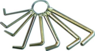
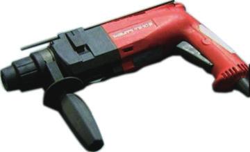
29 Service Manual Main Tools for 1. Level meter, measuring tape 2. Screw driver 3. Impact drill, drill head, electric drill Electroprobe 5. Universal meter 6. Torque wrench, open-end wrench, inner hexagon spanner 7. Electronic leakage detector 8. Vacuum pump 9. Pressure meter 10. Pipe pliers, pipe cutter 11. Pipe expander, pipe bender 12. Soldering appliance, refrigerant container
30 8. Installation 8.1 Installation Dimension Diagram At least 250cm At least 15cm At least 300cm Space to the obstruction At least 50cm Space to the floor Space to the ceiling Space to the wall At least 15cm At least 15cm Space to the wall Space to the obstruction Space to the obstruction At least 30cm At least 30cm Drainage pipe Space to the wall Space to the obstruction At least 200cm At least 50cm Space to the obstruction 27
31 Installation procedures Start installation Preparation before installation Read the requirements for electric connection select installation location Prepare tools Select indoor unit installation location Select outdoor unit installation location Install wall-mounting frame, drill wall holes Connect pipes of indoor unit and drainage pipe Connect wires of indoor unit Install the support of outdoor unit (select it according to the actual situation) Fix outdoor unit Install drainage joint of outdoor unit (only for cooling and heating unit) Bind up pipes and hang the indoor unit Make the bound pipes pass through the wall hole and then connect outdoor unit Connect pipes of outdoor unit Connect wires of outdoor unit Neaten the pipes Vacuum pumping and leakage detection Check after installation and test operation Finish installation Note: this flow is only for reference; please find the more detailed installation steps in this section. 28
32 8.2 Installation Parts-checking No. Name No. Name 1 Indoor unit 8 Sealing gum 2 Outdoor unit 9 Wrapping tape 3 Connection pipe 10 Support of outdoor unit 4 Drainage pipe 11 Fixing screw 5 Wall-mounting Drainage plug(cooling 12 frame and heating unit) 6 Connecting Owner s manual, 13 cable(power cord) remote controller 7 Wall pipe Note: 1.Please contact the local agent for installation. 2.Don't use unqualified power cord. 8.3 Selection of Installation Location 1. Basic Requirement: Installing the unit in the following places may cause malfunction. If it is unavoidable, please consult the local dealer: (1) The place with strong heat sources, vapors, flammable or explosive gas, or volatile objects spread in the air. (2) The place with high-frequency devices (such as welding machine, medical equipment). (3) The place near coast area. (4) The place with oil or fumes in the air. (5) The place with sulfureted gas. (6) Other places with special circumstances. 2. Indoor Unit: (1) There should be no obstruction near air inlet and air outlet. (2) Select a location where the condensation water can be dispersed easily and won't affect other people. (3) Select a location which is convenient to connect the outdoor unit and near the power socket. (4) Select a location which is out of reach for children. (5) The location should be able to withstand the weight of indoor unit and won't increase noise and vibration. (6) The appliance must be installed 2.5m above floor. (7) Don't install the indoor unit right above the electric appliance. (8) The appliance shall not be installed in the laundry. 3. Outdoor Unit: (1) Select a location where the noise and outflow air emitted by the outdoor unit will not affect neighborhood. (2) The location should be well ventilated and dry, in which the outdoor unit won't be exposed directly to sunlight or strong wind. (3) The location should be able to withstand the weight of outdoor unit. (4) Make sure that the installation follows the requirement of installation dimension diagram. (5) Select a location which is out of reach for children and far away from animals or plants.if it is unavoidable, please add fence for safety purpose. 8.4 Electric Connection Requirement 1. Safety Precaution (1) Must follow the electric safety regulations when installing the unit. (2) According to the local safety regulations, use qualified power supply circuit and air switch. (3) Make sure the power supply matches with the requirement of air conditioner. Unstable power supply or incorrect wiring may result in electric shock,fire hazard or malfunction. Please install proper power supply cables before using the air conditioner. Air-conditioner Air switch capacity 09/12K 10A (4) Properly connect the live wire, neutral wire and grounding wire of power socket. (5) Be sure to cut off the power supply before proceeding any work related to electricity and safety. (6) Do not put through the power before finishing installation. (7) If the supply cord is damaged, it must be replaced by the manufacturer, its service agent or similarly qualified persons in order to avoid a hazard. (8) The temperature of refrigerant circuit will be high, please keep the interconnection cable away from the copper tube. 2. Grounding Requirement: (1) The air conditioner is first class electric appliance. It must be properly grounding with specialized grounding device by a professional. Please make sure it is always grounded effectively, otherwise it may cause electric shock. (2) The yellow-green wire in air conditioner is grounding wire, which can't be used for other purposes. (3) The grounding resistance should comply with national electric safety regulations. (4) The appliance must be positioned so that the plug is accessible. (5) An all-pole disconnection switch having a contact separation of at least 3mm in all poles should be connected in fixed wiring. (6) Including an air switch with suitable capacity, please note the following table. Air switch should be included magnet buckle and heating buckle function, it can protect the circuitshort and overload. (Caution: please do not use the fuse only for protect the circuit) 8.5 Installation of Indoor Unit 1. Choosing Installation Iocation Recommend the installation location to the client and then confirm it with the client. 2. Install Wall-mounting Frame (1) Hang the wall-mounting frame on the wall; adjust it in horizontal position with the level meter and then point out the screw fixing holes on the wall. (2) Drill the screw fixing holes on the wall with impact drill (the specification of drill head should be the same as the plastic expansion particle) and then fill the plastic expansion particles 29
33 in the holes. (3) Fix the wall-mounting frame on the wall with tapping screws (ST4.2X25TA) and then check if the frame is firmly installed by pulling the frame. If the plastic expansion particle is loose, please drill another fixing hole nearby. 3. Install Wall-mounting Frame (1) Choose the position of piping hole according to the direction of outlet pipe. The position of piping hole should be a little lower than the wall-mounted frame.(as show in Fig.1) Wall Space to the wall above 150mm Left Φ55mm Rear piping hole Mark in the middle of it Fig.1 Level meter Space to the wall above 150mm Wall Right Φ55mm Rear piping hole 5. Connect the Pipe of Indoor Unit (1) Aim the pipe joint at the corresponding bellmouth.(as show in Fig.5) (2) Pretightening the union nut with hand. (3) Adjust the torque force by referring to the following sheet. Place the open-end wrench on the pipe joint and place the torque wrench on the union nut. Tighten the union nut with torque wrench.(as show in Fig.6) (4) Wrap the indoor pipe and joint of connection pipe with insulating pipe, and then wrap it with tape.(as show in Fig.7) Pipe joint Union nut Pipe Fig.5 Torque wrench Indoor pipe Open-end wrench Union nut Fig.6 Pipe (2) Open a piping hole with the diameter of Φ55mm on the selected outlet pipe position.in order to drain smoothly, slant the piping hole on the wall slightly downward to the outdoor side with the gradient of 5-10.(As show in Fig.2) Insulating pipe Fig.7 Indoor Outdoor Refer to the following table for wrench moment of force: 5-10 Right Rear right Φ55mm Fig.2 Note: (1) Pay attention to dust prevention and take relevant safety measures when opening the hole. (2) The plastic expansion particles are not provided and should be bought locally. 4. Outlet Pipe (1) The pipe can be led out in the direction of right, rear right, left or rear left.(as show in Fig.3) (2) When selecting leading out the pipe from left or right, please cut off the corresponding hole on the bottom case.(as show in Fig.4) Fig.3 Left Rear left Hex nut diameter(mm) Tightening torque(n.m) Φ6 15~20 Φ ~40 Φ12 45~55 Φ16 60~65 Φ19 70~75 6. Install Drain Hose (1) Connect the drain hose to the outlet pipe of indoor unit.(as show in Fig.8) (2) Bind the joint with tape.(as show in Fig.9) Drain hose Outlet pipe Tape Drain hose Fig.9 Fig.8 Outlet pipe Note: (1) Add insulating pipe in the indoor drain hose in order to prevent condensation. (2) The plastic expansion particles are not provided. (As show in Fig.10) Left Right Drain hose Cut off the hole Fig.4 Insulating pipe Fig.10 30
34 7. Connect Wire of Indoor Unit (1) Open the panel, remove the screw on the wiring cover and then take down the cover.(as show in Fig.11) Fig.11 Panel Screw Wiring cover (2) Make the power connection wire go through the cable-cross hole at the back of indoor unit and then pull it out from the front side.(as show in Fig.12) Cable-cross hole 8. Bind up Pipe (1) Bind up the connection pipe, power cord and drain hose with the band.(as show in Fig.14) (2) Reserve a certain length of drain hose and power cord for installation when binding them. When binding to a certain degree, separate the indoor power and then separate the drain hose.(as show in Fig.15) (3) Bind them evenly. (4) The liquid pipe and gas pipe should be bound separately at the end. Indoor unit Indoor and outdoor power cord Gas pipe Power connection wire Fig.14 Band Liquid pipe Drain hose Note:This step only applicable for N.American models. Fig.12 Connection pipe Drain hose Band (3) Remove the wire clip; connect the power connection wire to the wiring terminal according to the color; tighten the screw and then fix the power connection wire with wire clip.(as show in Fig.13) Indoor power cord Fig.15 N(1) 2 3 blue black brown yellowgreen Note: (1) The power cord and control wire can't be crossed or winding. (2) The drain hose should be bound at the bottom. Fig.13 Outdoor unit connection Note: The wiring connect is for reference only, please refer to the actual one. (4) Put wiring cover back and then tighten the screw. (5) Close the panel. Note: (1) All wires of indoor unit and outdoor unit should be connected by a professional. (2) If the length of power connection wire is insufficient, please contact the supplier for a new one. Avoid extending the wire by yourself. (3) For the air conditioner with plug, the plug should be reachable after finishing installation. (4) For the air conditioner without plug, an air switch must be installed in the line. The air switch should be all-pole parting and the contact parting distance should be more than 3mm. 9. Hang the Indoor Unit (1) Put the bound pipes in the wall pipe and then make them pass through the wall hole. (2) Hang the indoor unit on the wall-mounting frame. (3) Stuff the gap between pipes and wall hole with sealing gum. (4) Fix the wall pipe.(as show in Fig.16) (5) Check if the indoor unit is installed firmly and closed to the wall.(as show in Fig.17) Indoor Wall pipe Fig.16 Outdoor Sealing gum Fig.17 Upper hook Lower hook of wall-mounting frame Note: Do not bend the drain hose too excessively in order to prevent blocking. 31
35 8.6 Installation of Outdoor Unit 1. Fix the Support of Outdoor Unit(Select it According to the Actual Installation Situation) (1) Select installation location according to the house structure. (2) Fix the support of outdoor unit on the selected location with expansion screws. Note: (1) Take sufficient protective measures when installing the outdoor unit. (2) Make sure the support can withstand at least four times the unit weight. (3) The outdoor unit should be installed at least 3cm above the floor in order to install drain joint.(as show in Fig.18) (4) For the unit with cooling capacity of 2300W~5000W, 6 expansion screws are needed; for the unit with cooling capacity of 6000W~8000W, 8 expansion screws are needed; for the unit with cooling capacity of 10000W~16000W, 10 expansion screws are needed. Refer to the following table for wrench moment of force: Hex nut diameter(mm) Tightening torque(n.m) Φ6 15~20 Φ ~40 Φ12 45~55 Φ16 60~65 Φ19 70~75 5. Connect Outdoor Electric Wire (1) Remove the wire clip; connect the power connection wire to the wiring terminal according to the color; fix the power connection wire with screws.(as show in Fig.23) N(1) blue N black 2 3 L brown yellowgreen yellow- green (green) brown(black) L blue(white) N POWER Indoor unit connection Handle At least 3cm above the floor Fig.18 Fig Install Drain Joint(Only for cooling and heating unit) (1) Connect the outdoor drain joint into the hole on the chassis. (2) Connect the drain hose into the drain vent.(as show in Fig.19) 3. Fix Outdoor Unit (1) Place the outdoor unit on the support. (2) Fix the foot holes of outdoor unit with bolts.(as show in Fig.20) Foot holes Foot holes Drain vent Drain hose Chassis Outdoor drain joint Screw Handle Fig.20 Fig Connect Indoor and Outdoor Pipes (1) Remove the screw on the right handle of outdoor unit and then remove the handle.(as show in Fig.21) (2) Remove the screw cap of valve and aim the pipe joint at the bellmouth of pipe.(as show in Fig.22) Note: the wiring connect is for reference only, please refer to the actual one. (2) Fix the power connection wire with wire clip. Note: Fig.23 (1) After tightening the screw, pull the power cord slightly to check if it is firm. (2) Never cut the power connection wire to prolong or shorten the distance. 6. Neaten the Pipes (1) The pipes should be placed along the wall, bent reasonably and hidden possibly. Min. semidiameter of bending the pipe is 10cm. (2) If the outdoor unit is higher than the wall hole, you must set a U-shaped curve in the pipe before pipe goes into the room, in order to prevent rain from getting into the room.(as show in Fig.24) Wall Fig.25 The drain hos can't raise upwards U-shaped curve Liquid valve Liquid pipe gas pipe gas valve Fig.22 Pipe joint (3) Pretightening the union nut with hand. (4) Tighten the union nut with torque wrench. Union nut Fig.24 Note: Drain hose (1) The through-wall height of drain hose shouldn't be higher than the outlet pipe hole of indoor unit.(as show in Fig.25) (2) Slant the drain hose slightly downwards. The drain hose can't be curved, raised and fluctuant, etc.(as show in Fig.26) 32
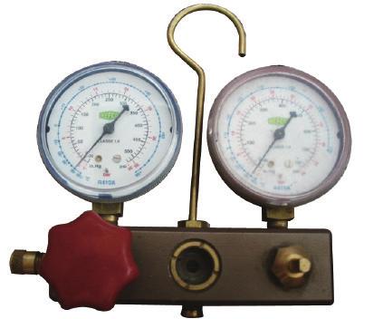
36 (3) The water outlet can't be placed in water in order to drain smoothly.(as show in Fig.27) The drain hose can't be fluctuant The drain hose can't be fluctuant Fig.26 The water outlet can't be fluctuant The water outlet can't be placed in water Fig Vacuum Pumping and Leak Detection 1. Use Vacuum Pump (1) Remove the valve caps on the liquid valve and gas valve and the nut of refrigerant charging vent. (2) Connect the charging hose of piezometer to the refrigerant charging vent of gas valve and then connect the other charging hose to the vacuum pump. (3) Open the piezometer completely and operate for 10-15min to check if the pressure of piezometer remains in -0.1MPa. (4) Close the vacuum pump and maintain this status for 1-2min to check if the pressure of piezometer remains in -0.1MPa. If the pressure decreases, there may be leakage. (5) Remove the piezometer, open the valve core of liquid valve and gas valve completely with inner hexagon spanner. (6) Tighten the screw caps of valves and refrigerant charging vent.(as show in Fig.28) 8.8 Check after Installation and Test Operation 1. Check after Installation Check according to the following requirement after finishing installation. No. Items to be checked Possible malfunction 1 Has the unit been The unit may drop, shake or installed firmly? emit noise. 2 Have you done the It may cause insufficient cooling refrigerant leakage test? (heating) capacity. 3 Is heat insulation of It may cause condensation and pipeline sufficient? water dripping. 4 Is water drained well? It may cause condensation and water dripping. Is the voltage of power 5 supply according to the It may cause malfunction or voltage marked on the damage the parts. nameplate? Is electric wiring and pipeline installed correctly? Is the unit grounded securely? Does the power cord follow the specification? Is there any obstruction It may cause malfunction or damage the parts. It may cause electric leakage. It may cause malfunction or damage the parts. It may cause insufficient cooling in air inlet and air outlet? (heating). The dust and sundries caused It may cause malfunction or during installation are damaging the parts. removed? The gas valve and liquid valve of connection pipe are open completely? It may cause insufficient cooling (heating) capacity. Liquid valve Gas valve Refrigerant charging vent Nut of refrigerant Charging vent Piezometer Valve cap Inner hexagon spanner Lo Vacuum pump Hi 2. Test Operation (1) Preparation of test operation The client approves the air conditioner installation. Specify the important notes for air conditioner to the client. (2) Method of test operation Put through the power, press ON/OFF button on the remote controller to start operation. Press MODE button to select AUTO, COOL, DRY, FAN and HEAT to check whether the operation is normal or not. If the ambient temperature is lower than 16, the air conditioner can t start cooling. Fig.28 Close Open 2. Leakage Detection (1) With leakage detector: Check if there is leakage with leakage detector. (2) With soap water: If leakage detector is not available, please use soap water for leakage detection. Apply soap water at the suspected position and keep the soap water for more than 3min. If there are air bubbles coming out of this position, there's a leakage. 33
37 9. Maintenance 9.1 Malfunction Analysis Note: When replacing the controller, be sure to insert the wire jumper into the new controller, otherwise the unit will display C5 Trip of breaker or The breaker trips at once when it is set to ON. Measure insulation resistance to ground to see if there is any leakage. Air conditioner can not start up blow of fuse The air conditioner does not react after it is powered ( after the plug is inserted, the buzzer does not sound and the remote startup has no response) The breaker trips in few minutes when it is set to ON. No power Power plug is not well plugged in and poor connection. Fuse of controller burnt out The transformer connection is loose or has bad contact or the transformer has malfunction. The circuit or the part of the air conditioner has malfunction. They heat and break the insulation and lead to short circuit or creepage. Measure the insulation resistance or eliminate the malfunction one by one. If the breaker itself has malfunction, then replace the breaker. Check power supply circuit. Check if the plug is properly plugged in and make the loose contact firm. Change controller fuse Fasten the wiring; measure the output voltage of the transformer, if it is incorrect, change the transformer. Controller is broken Check remote controller Remote controller is short of power Change batteries The remote controller does not receive signals (after it is powered, the buzzer will sound, unless it has malfunction) Remote controller malfunction Receiver loose or poor connection Receiver is broken First, press the manual switch button AUTO,if there is no response,check based on the above methods. If it runs normally after pressing the button, check again whether the installation position and the connection wire of the reception head is correct. If it is correct,then replace the receiver or the remote controller. Power voltage is too low Check the voltage. If it is lower than 10% of the rated voltage, check the cause, improve the power supply condition and add the stabilized voltage power supply. 34
38 Improper set of temperature Adjust set temperature If cooling (heating) load is proper Check the forecasted load of cooling (heating) Malfunction of refrigerant flow The refrigerant has leakage or is insufficient Leakage between the high pressure and the low pressure inside the compressor Malfunction of four-way valve Check and fill the leakage, then vacuumize it and supplement the refrigerant as required Replace the compressor Replace the four-way valve Local block of capillary Replace the capillary Poor COOL(HEAT) operation Judge whether the system is blocked by observing the condensation of evaporator and the pressure value of the high Blockage of cooling system pressure manometer and take measures to deal with the system. Heat insulation for the connection Make sure that heat insulation for the thick and thin pipes pipes of the indoor unit and the outdoor unit is bad. is good. Heat insulation must also be provided for the joint andthe exposed part of the copper pipe. Block of outdoor heat exchanger the heat Clean the dust accumulated on the surface of exchanger. Air circulation is insufficient Air filter were blocked Fan speed was set too slow Fan rotation speed becomes low Clean the filter To set the fan speed to high or middle speed Capacitor Replace the capacitor damage Motor damage Replace the motor The installation position of the outdoor unit is not appropriate. Good ventilation must be provided for the installation position of the outdoor unit. The outdoor temperature is too high. The air tightness is not enough. People come in and out too frequently. There are heating devices indoors. Properly install the rainproof plate or the sunproof plate. If the maximum cool air still can not meet the requirement, it is suggested to replace the air conditioner. Keep certain air tightness indoors, try not to use electricalappliance with large quantity of heat 35
39 Improper set of temperature Adjust set temperature If cooling (heating) load is proper Check the forecasted load of cooling (heating) Malfunction of refrigerant flow The refrigerant has leakage or is insufficient Leakage between the high pressure and the low pressure inside the compressor Malfunction of four-way valve Check and fill the leakage, then vacuumize it and supplement the refrigerant as required Replace the compressor Replace the four-way valve Local block of capillary Replace the capillary Poor COOL(HEAT) operation Heat insulation for the connection pipes of the indoor unit and the outdoor unit is bad. Blockage of cooling system Block of outdoor heat exchanger Judge whether the system is blocked by observing the condensation of evaporator and the pressure value of the high pressure manometer and take measures to deal with the system. Make sure that heat insulation for the thick and thin pipes is good. Heat insulation must also be provided for the joint andthe exposed part of the copper pipe. Clean the dust accumulated on the surface of the heat exchanger. Air circulation is insufficient Air filter were blocked Fan speed was set too slow Fan rotation speed becomes low Clean the filter To set the fan speed to high or middle speed Capacitor Replace the capacitor damage Motor damage Replace the motor The installation position of the outdoor unit is not appropriate. Good ventilation must be provided for the installation position of the outdoor unit. The outdoor temperature is too high. The air tightness is not enough. People come in and out too frequently. There are heating devices indoors. Properly install the rainproof plate or the sunproof plate. If the maximum cool air still can not meet the requirement, it is suggested to replace the air conditioner. Keep certain air tightness indoors, try not to use electricalappliance with large quantity of heat 36
40 The torque of the swing motor is not enough The swing fan does not run. Wrong connection The controller is damaged(ic2003 is damaged, the swing relay can not close, etc) First, check whether the connection is wrong. If no, replace the parts In cool, heat mode, the outdoor unit and compressor will not run. Controller malfunction (IC2003 broken, creepage of parallel capacitor of relay loop, relay is broken etc.) Wire loose or wrong connection Improper setting of temperature Change controller Correctly wire according to the drawing Adjust setting temp. Water leakage Drainage pipe blocked or broken Wrap of refrigerant pipe joint is not close enough. Change drainage pipe Re-wrap and make it tight. Fan of indoor unit contacts other parts Adjust fan location Foreign object in indoor unit Take out the foreign object Abnormal sound and shake Compressor shakes too much Touch of pipeline of outdoor unit Touch of inner plates Adjust support washer of compressor, and tighten loosen screws Separate the touching pipeline. 1. Tighten connect screw. 2. Stick absorbing clay between plates. Louver of outdoor unit touched outer case. Adjust location of louver. Abnormal sound inside compressor Change compressor 37
41 9.2 Flashing LED of Indoor/Outdoor Unit and Primary Judgement Display Method of Indoor Unit Indicator Display (during Malfunction NO. Dual-8 blinking, ON 0.5s and OFF Name Code 0.5s) Display Operation Cool Heating Display Method of Outdoor Unit Indicator has 3 kinds of display status and during blinking, ON 0.5s and OFF A/C status 0.5s Yellow Red Green Indicator Indicator Indicator Indicator Indicator Indicator Possible Causes 1 High pressure protection of system E1 OFF 3s and blink once During cooling and drying operation, except indoor fan operates, all loads stop operation. During heating operation, the complete unit stops. Possible reasons: 1. Refrigerant was superabundant; 2. Poor heat exchange (including and bad radiating environment ); Ambient temperature is too high Antifreezing protection System block or refrigerant leakage High discharge temperature protection of compressor E2 E3 E4 and blink twice and blink 3 times and blink 4 times and blink 3 times and blink 7 times and blink 9 times During cooling and drying operation, compressor and outdoor fan stop while indoor fan operates. The Dual-8 Code Display will show E3 until the low pressure switch stop operation. During cooling and drying operation, compressor and outdoor fan stop while indoor fan operates. During heating operation, all loads stop. 1. Poor air-return in indoor unit; 2. Fan speed is abnormal; 3. Evaporator is dirty. 1.Low-pressure protection 2.Low-pressure protection of system 3.Low-pressure protection of compressor Please refer to the malfunction analysis (discharge protection, overload). 5 Overcurrent protection E5 and blink 5 times and blink 5 times During cooling and drying operation, compressor and outdoor fan stop while indoor fan operates. During heating operation, all loads stop. 1. Supply voltage is unstable; 2. Supply voltage is too low and load is too high; 3. Evaporator is dirty. 6 Communication Malfunction E6 and blink 6 times OFF During cooling operation, compressor stops while indoor fan motor operates. During heating operation, the complete unit stops. Refer to the corresponding malfunction analysis. 7 High temperature resistant protection E8 and blink 8 times and blink 6 times During cooling operation: compressor will stop while indoor fan will operate. During heating operation, the complete unit stops. Refer to the malfunction analysis (overload, high temperature resistant). 8 EEPROM malfunction EE and blink and blink 15 times 11 times During cooling and drying operation, compressor will stop Replace outdoor control panel AP1 while indoor fan will operate; During heating operation, the complete unit will stop 9 Limit/ decrease frequency due to high temperature of module EU and blink and blink 6 times 6 times All loads operate normally, while operation frequency for compressor is decreased Discharging after the complete unit is de-energized for 20mins, check whether the thermal grease on IPM Module of outdoor control the radiator is inserted tightly. If its no use, please replace control panel AP1. 10 Malfunction protection of jumper cap C5 and blink 15 times Wireless remote receiver and button are effective, but can not dispose the related command 1. No jumper cap insert on mainboard. 2. Incorrect insert of jumper cap. 3. Jumper cap damaged. 4. Abnormal detecting circuit of mainboard. 38
42 NO. Malfunction Name Display Method of Indoor Unit Indicator Display (during Dual-8 blinking, ON 0.5s and OFF Code 0.5s) Display Operation Cool Heating Display Method of Outdoor Unit Indicator has 3 kinds of display status and during blinking, ON 0.5s and OFF 0.5s Yellow Red Green Indicator Indicator Indicator Indicator Indicator Indicator A/C status Possible Causes 11 Gathering refrigerant Fo and blink 1 times and blink 1 times When the outdoor unit receive signal of Gathering refrigerant,the system will be forced to run under cooling mode for gathering refrigerant Nominal cooling mode 12 Indoor ambient temperature sensor is open/short circuited F1 and blink once During cooling and drying operation, indoor unit operates while other loads will stop; during heating operation, the complete unit will stop operation. 1. Loosening or bad contact of indoor ambient temp. sensor and mainboard terminal. 2. Components in mainboard fell down leads short circuit. 3. Indoor ambient temp. sensor damaged.(check with sensor resistance value chart) 4. Mainboard damaged. 13 Indoor evaporator temperature sensor is open/short circuited F2 and blink twice AC stops operation once reaches the setting temperature. Cooling, drying: internal fan motor stops operation while other loads stop operation; heating: AC stop operation 1. Loosening or bad contact of Indoor evaporator temp. sensor and mainboard terminal. 2. Components on the mainboard fall down leads short circuit. 3. Indoor evaporator temp. sensor damaged.(check temp. sensor value chart for testing) 4. Mainboard damaged Outdoor ambient temperature sensor is open/short circuited Outdoor condenser temperature sensor is open/short circuited Outdoor discharge temperature sensor is open/short circuited Limit/ decrease frequency due to overload F3 F4 F5 F6 and blink 3 times and blink 4 times and blink 5 times and blink for 6 times and blink 6 times and blink 5 times and blink 7 times and blink 3 times During cooling and drying operating, compressor stops while indoor fan operates; During heating operation, the complete unit will stop operation During cooling and drying operation, compressor stops while indoor fan will operate; During heating operation, the complete unit will stop operation. During cooling and drying operation, compressor will sop after operating for about 3 mins, while indoor fan will operate; During heating operation, the complete unit will stop after operating for about 3 mins. All loads operate normally, while operation frequency for compressor is decreased Outdoor temperature sensor hasnt been connected well or is damaged. Please check it by referring to the resistance table for temperature sensor) Outdoor temperature sensor hasnt been connected well or is damaged. Please check it by referring to the resistance table for temperature sensor) 1.Outdoor temperature sensor hasnt been connected well or is damaged. Please check it by referring to the resistance table for temperature sensor) 2.The head of temperature sensor hasnt been inserted into the copper tube Refer to the malfunction analysis (overload, high temperature resistant) 18 Decrease frequency due to overcurrent F8 and blink 8 times and blink once All loads operate normally, while operation frequency for compressor is decreased The input supply voltage is too low; System pressure is too high and overload 39
43 NO. Malfunction Name Display Method of Outdoor Display Method of Indoor Unit Unit Indicator has 3 kinds of Indicator Display (during display status and during Dual-8 blinking, ON 0.5s and OFF blinking, ON 0.5s and OFF Code 0.5s) 0.5s Display Operation Cool Heating Yellow Red Green Indicator Indicator Indicator Indicator Indicator Indicator A/C status Possible Causes 19 Decrease frequency due to high air discharge F9 and blink 9 times and blink twice All loads operate normally, while operation frequency for compressor is decreased Overload or temperature is too high; Malfunction of electric expansion valve (EKV) 20 Limit/ decrease frequency due to antifreezing FH and blink and blink 2 times 2 times and blink 4 times All loads operate normally, while operation frequency for compressor is decreased Poor air-return in indoor unit or fan speed is too low 21 Voltage for DC bus-bar is too high PH and blink 11 times and blink 13 times 1. Measure the voltage of position L and N on wiring board (XT), if the During cooling and drying voltage is higher than 265VAC, turn operation, compressor will stop on the unit after the supply voltage while indoor fan will operate; is increased to the normal range. 2.If the AC input is normal, During heating operation, the measure the voltage of electrolytic complete unit will stop capacitor C on control panel (AP1), operation. if its normal, theres malfunction for the circuit, please replace the control panel (AP1) 22 Voltage of DC bus-bar is too low PL and and blink blink 21 times 12 times During cooling and drying operation, compressor will stop while indoor fan will operate; During heating operation, the complete unit will stop 1. Measure the voltage of position L and N on wiring board (XT), if the voltage is higher than 150VAC, turn on the unit after the supply voltage is increased to the normal range. 2.If the AC input is normal, measure the voltage of electrolytic capacitor C on control panel (AP1), if its normal, theres malfunction for the circuit, please replace the control panel (AP1) 23 Compressor Min frequence in test state P0 (during (during blinking, blinking, ON ON 0.25s 0.25s and OFF and OFF 0.25s) 0.25s) Showing during min. cooling or min. heating test 24 Compressor rated frequence in test state P1 (during (during blinking, blinking, ON ON 0.25s 0.25s and OFF and OFF 0.25s) 0.25s) Showing during nominal cooling or nominal heating test 25 Compressor maximum frequence in test state P2 (during (during blinking, blinking, ON ON 0.25s 0.25s and OFF and OFF 0.25s) 0.25s) Showing during max. cooling or max. heating test 40
44 NO. Malfunction Name Display Method of Outdoor Display Method of Indoor Unit Unit Indicator has 3 kinds of Indicator Display (during display status and during Dual-8 blinking, ON 0.5s and OFF blinking, ON 0.5s and OFF Code 0.5s) 0.5s Display Operation Cool Heating Yellow Red Green Indicator Indicator Indicator Indicator Indicator Indicator A/C status Possible Causes 26 Compressor intermediate frequence in test state P3 (during (during blinking, blinking, ON ON 0.25s 0.25s and OFF and OFF 0.25s) 0.25s) Showing during middle cooling or middle heating test 27 Overcurrent protection of phase current for compressor P5 and blink 15 times During cooling and drying Refer to the malfunction operation, compressor will stop analysis (IPM protection, loss while indoor fan will operate; of synchronism protection and During heating operation, the overcurrent protection of phase complete unit will stop current for compressor. operation. 28 Charging malfunction of capacitor PU and blink 17 times During cooling and drying operation, compressor will stop Refer to the part three charging while indoor fan will operate; malfunction analysis of capacitor During heating operation, the complete unit will stop 29 Malfunction of module temperature sensor circuit P7 and blink 18 times During cooling and drying operation, compressor will stop while indoor fan will operate; Replace outdoor control panel AP1 During heating operation, the complete unit will stop 30 Module high temperature protection P8 and blink 19 times During cooling operation, compressor will stop while indoor fan will operate; During heating operation, the complete unit will stop After the complete unit is deenergized for 20mins, check whether the thermal grease on IPM Module of outdoor control panel radiator is inserted tightly. If its no use, please replace control panel AP1. 31 Decrease frequency due to high temperature resistant during heating operation H0 and blink 10 times All loads operate normally, while operation frequency for compressor is decreased Refer to the malfunction analysis (overload, high temperature resistant) 32 Static dedusting protection H2 and blink twice 33 Overload protection for compressor H3 and blink and blink 3 times 8 times During cooling and drying 1. Wiring terminal OVC-COMP operation, compressor will stop is loosened. In normal state, the while indoor fan will operate; resistance for this terminal should During heating operation, the be less than 1ohm. complete unit will stop 2.Refer to the malfunction analysis ( operation. discharge protection, overload) 41
45 NO Malfunction Name System is abnormal IPM protection Display Method of Outdoor Display Method of Indoor Unit Unit Indicator has 3 kinds of Indicator Display (during display status and during Dual-8 blinking, ON 0.5s and OFF blinking, ON 0.5s and OFF A/C status Possible Causes Code 0.5s) 0.5s Display Operation Cool Heating Yellow Red Green Indicator Indicator Indicator Indicator Indicator Indicator During cooling and drying operation, compressor will stop Refer to the malfunction analysis while indoor fan will operate; H4 and blink and blink (overload, high temperature 4 times 6 times During heating operation, the resistant) complete unit will stop operation. During cooling and drying Refer to the malfunction operation, compressor will stop analysis (IPM protection, loss while indoor fan will operate; H5 and blink and blink of synchronism protection and 5 times 4 times During heating operation, the overcurrent protection of phase complete unit will stop current for compressor. operation. 36 Module temperature is too high H5 and blink and blink 5 times 10 times Internal motor (fan motor) do not operate Desynchronizing of compressor PFC protection H6 H7 HC and blink 11 times and blink 7 times and blink and blink 6 times 14 times Internal fan motor, external fan motor, compressor and electric heater stop operation,guide louver stops at present location. During cooling and drying operation, compressor will stop while indoor fan will operate; During heating operation, the complete unit will stop operation. 1. Bad contact of DC motor feedback terminal. 2. Bad contact of DC motor control end. 3. Fan motor is stalling. 4. Motor malfunction. 5. Malfunction of mainboard rev detecting circuit. Refer to the malfunction analysis (IPM protection, loss of synchronism protection and overcurrent protection of phase current for compressor. During cooling and drying operation, compressor will stop while indoor fan will operate; Refer to the malfunction analysis During heating operation, the complete unit will stop operation. 40 Outdoor DC fan motor malfunction L3 and blink 23 times and blink 14 times Outdoor DC fan motor DC fan motor malfunction or malfunction lead to compressor system blocked or the connector stop operation, loosed 41 power protection L9 and blink 20 times and blink 9 times compressor stop operation and Outdoor fan motor will stop 30s latter, 3 minutes latter fan motor and compressor will restart To protect the electronical components when detect high power Indoor unit and outdoor unit doesn't match Failure startup LP LC and blink 19 times and blink 11 times and blink 16 times compressor and Outdoor fan motor can t work Indoor unit and outdoor unit doesn't match During cooling and drying operation, compressor will stop while indoor fan will operate; Refer to the malfunction analysis During heating operation, the complete unit will stop operation. 42
46 NO. Malfunction Name Display Method of Indoor Unit Indicator Display (during Dual-8 blinking, ON 0.5s and OFF Code 0.5s) Display Operation Cool Heating Display Method of Outdoor Unit Indicator has 3 kinds of display status and during blinking, ON 0.5s and OFF 0.5s Yellow Red Green Indicator Indicator Indicator Indicator Indicator Indicator A/C status Possible Causes 44 Malfunction of phase current detection circuit for compressor U1 and blink 13 times During cooling and drying operation, compressor will stop while indoor fan will operate; Replace outdoor control panel AP1 During heating operation, the complete unit will stop 45 Malfunction of voltage dropping for DC bus-bar U3 and blink 20 times During cooling and drying operation, compressor will stop while indoor fan will operate; Supply voltage is unstable During heating operation, the complete unit will stop 46 Malfunction of complete units current detection U5 and blink 13 times During cooling and drying operation, the compressor will stop while indoor fan will operate; During heating operating, the complete unit will stop operation. Theres circuit malfunction on outdoor units control panel AP1, please replace the outdoor units control panel AP1. 47 The four-way valve is abnormal U7 and blink 20 times 1.Supply voltage is lower than If this malfunction occurs AC175V; during 2.Wiring terminal 4V is loosened or heating operation, the complete broken; unit will stop operation. 3.4V is damaged, please replace 4V. 48 Zerocrossing malfunction of outdoor unit U9 and blink 18 times During cooling operation, compressor will stop while indoor fan will operate; during heating,the complete unit will stop operation. Replace outdoor control panel AP1 49 Frequency limiting (power) and blink 13 times Compressor is opencircuited The temperature for turning on the unit is reached Frequency limiting (module temperature) and blink once and blink 8 times and blink 11 times 43
47 NO. Malfunction Name Display Method of Indoor Unit Display Method of Outdoor Unit Indicator Display (during Indicator has 3 kinds of display Dual-8 blinking, ON 0.5s and OFF status and during blinking, ON Code 0.5s) 0.5s and OFF 0.5s Display Operation Cool Heating Yellow Red Green Indicator Indicator Indicator Indicator Indicator Indicator A/C status Possible Causes 53 Normal communication continously 54 Defrosting and blink once (during and blink blinking, twice ON 10s and OFF 0.5s) Defrosting will occur in heating mode. Compressor will operate while indoor fan will stop operation. Its the normal state 55 Zero-crossing inspection circuit malfunction of the IDU fan motor U8 Flash 17 times every 3s Operation of remote controller or control panel is available, but the unit won t act. 1. Discharging speed of capacitor is slow, which lead to wrong judgement of controller. Zero-crossing detection circuit of main board is abnormal Refer to maintenance flowchart 44
48 45
49 Analysis or processing of some of the malfunction display: 1. Compressor discharge protection Possible causes: shortage of refrigerant; blockage of air filter; poor ventilation or air flow short pass for condenser; the system has noncondensing gas (such as air, water etc.); blockage of capillary assy (including filter); leakage inside four-way valve causes incorrect operation; malfunction of compressor; malfunction of protection relay; malfunction of discharge sensor; outdoor temperature too high. Processing method: refer to the malfunction analysis in the above section. 2. Low voltage overcurrent protection Possi ble cause: Sudden drop of supply voltage. 3. Communication malfunction Processing method: Check if communication signal cable is connected reliably. 4. Sensor open or short circuit Processing method: Check whether sensor is normal, connected with the corre sponding position on the controller and if damage of lead wire is found. 5. Compressor over load protection Possible causes: insufficient or too much refrigrant; blockage of capillary and increase of suction temp.; improper running of compressor, burning in or stuck of bearing, damage of discharge valve; malfunction of protector. Processing method: adjust refrigerant amount; replace the capillary; replace the compressor; use universal meter to check if the contactor of compress or is fine when it is not overheated, if not replace the protector. 6. System malfunction i.e.overload protection.when tube temperature(check the temperature of outdoor heat exchanger when cooling and check the temperatur e of indoor heat exchanger when heating) is too high, protectionwill beactivated. Possi ble causes: Outdoor temperature is too high when cooling; insufficient outdoor air circulation; refrigerant flow malfunction. please refer to the malfunction analysis in the previous section for handling method. 7. IPM module protection Processing method:once the module malfunction happens,if it persists for a long time and can not be selfcanceled, cut off the power and turn off the unit,and then re-energize the unit again after about 10 min.after repeating the procedure for sever times, if the malfunction still exists,replace the module. 46
50 9.3 How to Check Simply the Main Part Indoor Unit (1) Malfunction of Temperature Sensor F1, F2 Main detection points: Is the wiring terminal between the temperature sensor and the controller loosened or poorly contacted? Is there short circuit due to trip-over of the parts? Is the temperature sensor broken? Is mainboard broken? Malfunction diagnosis process: Troubleshooting for F1,F2 malfunction Is the wiring terminal between the temperature sensor and the controller loosened or poorly contacted? yes Insert the temperature sensor tightly no no Is malfunction eliminated Is there short circuit due to trip - over of the parts? yes Make the parts upright no no Is malfunction eliminated yes Is the temperature sensor normal according to the Resistance Table? no Replace it with a temperature sensor with the same model yes no Is malfunction removed yes Replace the mainboard with the same model. yes End 47
51 (2) Malfunction of Blocked Protection of IDU Fan Motor H6 Main detection points: Is the control terminal of PG motor connected tightly? Is the feedback interface of PG motor connected tightly? The fan motor can't operate? The motor is broken? Detectioncircuit of the mainboard is defined abnormal? Malfunction diagnosis process: Start While power is off stir the blade with a tool to see whether the blade rotates no smoothly Tighten the screw; reassemble the blade, motor and shaft bearing rubber base sub-assy to make sure there is no foreign object between them yes no Is malfunction eliminated yes Check if the connection of PG motor feedback terminal is firm. no yes Insert the control terminal of PG motor tightly no Is malfunction eliminated yes Check if the connection of PG motor control terminal is firm. no Reinstall the blade and motor correctly yes no Is malfunction eliminated yes Turn on the unit again; measure whether the output voltage on control terminal for PG motor is more than 50V within 1 min after the louvers are opened yes yes yes Is the motor started up Measure the voltage of this foot to neutral wire on the mainboard no no Replace PG motor no Is malfunction eliminated yes Replace the mainboard with the same model. End 48
52 (3) Malfunction of Protection of Jumper Cap C5 Main detection points: Is there jumper cap on the mainboard? Is the jumper cap inserted correctly and tightly? The jumper is broken? Detectioncircuit of the mainboard isdefined abnormal? Malfunction diagnosis process: Troubleshooting for C5 malfunction Is there jumper cap on the mainboard? yes no no Assemble the jumper cap with the same model Is malfunction eliminated Appearance of the jumper cap Is the jumper cap inserted correctly and tightly? no Insert the jumper cap tightly yes no Is malfunction eliminated yes Replace the jumper cap withthe same model yes Is malfunction eliminated yes no Replace the mainboard with the same model. End 49
53 (4) Malfunction of Zero-crossing Inspection Circuit Malfunction of the IDU Fan Motor U8 Main detection points: Instant energization afte de-energization while the capacitordischarges slowly? Malfunction diagnosis process: Troubleshooting for U8 malfunction Turn power off for 1minute,the turn back on U8 is still displayed No The unit returns to normal. Conclusion:U8 is displayed due to power off/on while the capacitor discharges slowly. Yes The zero-cross detection circuit of the mainboard is defined abnormal.replace the mainboard with the same model End 50
54 Outdoor Unit (1) Capacitor charge fault (Fault with outdoor unit) (AP1 below refers to the outdoor control panel) Main Check Points: Use AC voltmeter to check if the voltage between terminal L and N on the wiring board is within 210VAC~240VAC. Is the reactor (L) correctly connected? Is the connection loose or fallen? Is the reactor (L) damaged? Fault diagnosis process: Troubleshooting for F1,F2 malfunction Is the wiring terminal between the temperature sensor and the controller loosened or poorly contacted? yes Insert the temperature sensor tightly no no Is malfunction eliminated Is there short circuit due to trip - over of the parts? yes Make the parts upright no no Is malfunction eliminated yes Is the temperature sensor normal according to the Resistance Table? no Replace it with a temperature sensor with the same model yes no Is malfunction removed yes Replace the mainboard with the same model. yes End 51
55 (2) IPM Protection, Out-of-step Fault, Compressor Phase Overcurrent (AP1 below refers to the outdoor control panel) Main check points: Is the connection between control panel AP1 and compressor COMP secure? Loose? Is the connection in correct order? Is the voltage input of the machine within normal range? (Use AC voltmeter to measure the voltage between terminal L and N on the wiring board XT) Is the compressor coil resistance normal? Is the insulation of compressor coil against the copper tube in good condition? Is the working load of the machine too high? Is the radiation good? I s the charge volume of refrigerant correct? Fault diagnosis process: Energize and switch on IPM protection occurs after the machine has run for a period of time? Y Use AC voltmeter to measure the voltage between terminal L and N on the wiring board XT) If the voltage between terminal L and N on wiring board XT is within 210VAC~250VAC? N Check the supply voltage and restore it to 210VAC~250VAC Y Refer to the Electrical Wiring Diagram and check if the connection between AP1 and COMP is loose and if the connection order is correct. Y Please confirm: 1. If the indoor and outdoor heat exchangers are dirty? If they are obstructed by other objects which affect the heat exchange of indoor and outdoor unit. 2. If the indoor and outdoor fans are working normally? 3. If the environment temperature is too high, resulting in that the system pressure is too high and exceeds the permissible range? 4. If the charge volume of refrigerant is too much, resulting in that the system pressure is too high? 5. Other conditions resulting in that the system pressure becomes too high. Voltage between the two ends of celectrolytic capacitor is higher than 250V N Stop the unit and disconnect the power supply. Then, check the connection of capacitor C2 according to Electrical Wiring Diagram. Remove the wires on the two ends of capacitor C2. Then, use capacitance meter to measure the capacitor C2. Verify as per the Parameters Sheet. If capacitor C2 is failed? N If there is any abnormality described above? N Y Restart the unit. Before protection occurs, use DC voltmeter to measure the voltage between the two ends of electrolytic capacitor on control panel AP1 The connection of capacitor C2 is loose. Stop the unit and disconnect the power supply. Wait 20 minutes, or use DC voltmeter to measure the voltage between the two ends of capacitor C2, until the voltage is lower than 20V Replace the capacitor C2. Then, energize and start the unit. Replace the control panel AP1 Y N Take corrective actions according to Technical Service Manual, and then energize and start the unit. Replace the control panel AP1 N Y N If the unit can work normally? Reconnect the capacitor C2 according to Electrical Wiring Diagram. Then, Restart the unit. If the unit can work normallv? If the unit can work normally? N If the unit can work normally? N Y Y Y Y If the connection between AP1 and COMP is unsecure or the connection order is wrong? Y Connect the control panel AP1 and compressor COMP correctly according to the Electrical Wiring Diagram. Then, energize and start the unit. If the unit can work normally? Y Use ohmmeter to measure the resistance between the three terminals on compressor COMP, and compare the measurements with the compressor resistance on Service Manual. Use ohmmeter to measure the resistance between the two terminals of compressor COMP and copper tube. If the resistance is normal? N Resistance higher than 500MΩ? Y Replace the compressor COMP N Replace the control panel AP1 END 52
56 (3)High temperature and overload protection diagnosis (AP1 hereinafter refers to the control board of the outdoor unit) Mainly detect: Is outdoor ambient temperature in normal range? Are the outdoor and indoor fans operating normally? Is the heat dissipation environment inside and outside the unit good? Fault diagnosis process: Overheat and high temperature protection Is outdoor ambient temperature higher than 53? Y Normal protection, please operate it after the outdoor ambient temperature is normalized. N 20 minutes after the complete unit is powered off. Is heat dissipation of the indoor unit and outdoor unit abnormal? Y Improve the heat dissipation environment of the unit N Does the outdoor fan work normally? N 1. Check if the fan terminal OFAN is connected correctly 2. Resistance between any two terminals is measure by an ohm gauge and should be less than 1K Ohm. Y Replace the control panel AP1 Replace the fan capacitor C1 Replace the outdoor fan End 53
57 (4) Start-up failure (following AP1 for outdoor unit control board) Mainly detect: Whether the compressor wiring is connected correct? Is compressor broken? Is time for compressor stopping enough? Fault diagnosis process: Power on the unit Is stop time of the compressor longer than 3 minutes? N Restart it up after 3 minutes Y Does startup fail? Y Are the wires for the compressor connected correctly? Is connection sequence right? N Connect the wires as per the connection diagram Y Replace the control panel AP1 N If the fault is eliminated? N Replace the compressor Y End 54
58 (5) Out of step diagnosis for the compressor (AP1 hereinafter refers to the control board of the outdoor unit) Mainly detect: Is the system pressure too high? Is the input voltage too low? Fault diagnosis process: Out of step occurs once the unit is powered on. Out of step occurs in operation Is stop time of the compressor longer than 3 minutes? Is the outdoor fan working normally? Check if the fan terminal OFAN is connected correctly Replace the fan capacitor C1 Is the outdoor unit blocked by foreign objects? Remove foreign objects Replace the outdoor fan Are the wires for the compressor connected correctly? Is connection sequence right? Is the connection made in clockwise direction? Replace the control panel AP1 Connect the wires correctly Replace the control panel AP1 If the fault is eliminated? If the fault is eliminated? Replace the compressor Replace the compressor End End 55
59 (6) Overload and air exhaust malfunction diagnosis (following AP1 for outdoor unit control board) Mainly detect: Is the PMV connected well or not? Is PMV damaged? Is refrigerant leaked? Fault diagnosis process: 20 minutes after the complete unit is powered off Is the terminal FA for the electronic expansion valve connected correctly? Connect the wires correctly Resistances between the first four pins close to the terminal hole and the fifth pin are almost the same, less than 100 ohm. Replace the electronic expansion valve If the fault is eliminated? Replace the control panel AP1 If the fault is eliminated? Coolant leakage, refilling the coolant End 56
60 (7) Power factor correct or (PFC) fault (a fault of outdoor unit) (AP1 hereinafter refers to the control board of the outdoor unit) Mainly detect: Check if the reactor (L) of the outdoor unit and the PFC capacitor are broken Fault diagnosis process: Start Check wiring of the reactor (L) of the outdoor unit and the PFC capacitor Whether there is any damage or short-circuit? Y Replace it as per the wiring diagram and reconnect the wires If the fault is eliminated? N Remove the PFC capacitor and measure resistance between the two terminals. N Is the resistance around zero? Y The capacitor is short circuited and the capacitor should be replaced Restart the unit If the fault is eliminated? Y N Disconnect the terminals for the reactor and measure the resistance between the two terminals of the reactor by an ohm gauge N Whether there is any damage or short-circuit? Y Replace the reactor Restart the unit If the fault is eliminated? Y N Replace the control panel AP1 N Y End 57
61 (8) Communication malfunction: (following AP1 for outdoor unit control board) Mainly detect: Is there any damage for the indoor unit mainboard communication circuit? Is communication circuit damaged? Detect the indoor and outdoor units connection wire and indoor and outdoor units inside wiring is connect well or not, if is there any damage? Fault diagnosis process: Start Y Did the equipment operate normally before the failure occurs? N Check the wiring of the indoor and outdoor units with reference to the wiring diagram Check wiring inside of the indoor and outdoor units Y N Is the connection right? N The AP1 voltage detection circuit is at fault Y Are wires broken? Correctly connect the corresponding wires for the indoor and outdoor units with reference to the wiring diagram N If the fault is eliminated? N Check the communication circuit of the outdoor unit If the fault is eliminated? The communication circuit is abnormal Y Replace the main board AP1 of the outdoor unit N If the fault is eliminated? Replace the main board of the indoor unit N Y Y End Y 58
62 (9) Malfunction of Overcurrent Protection E5 Main detection points: Is the supply voltage unstable with big fluctuation? Is the supply voltage too low with overload? Hardware trouble? Malfunction diagnosis process: Start Is the supply voltage unstable with big fluctuation? yes Normal fluctuation should be within 10 % of the rated voltage on the nameplate Malfunction is eliminated yes no no Is the supply voltage too low with overload? yes Adjust the supply voltage to maintain it within normal range Malfunction is eliminated yes no no Is the indoor / outdoor heat exchanger dirty,or are the air inlet and outlet blocked? yes Clean the indoor and outdoor heat exchangers and remove the blockage of air inlet and outlet Malfunction is eliminated yes no no The fan is abnormal? Fan speed is too low or fan doesn t rotate yes Check the motor and reinstall the motor to have the fan run normally Malfunction is eliminated yes no no Measure the current of live wire on the main board with a clamp ampere meter. Is the current higher than the value of the overcurrent protection? no Replace the mainboard with the same model Malfunction is eliminated yes yes no Is there blockage inside the system? (Filth blockage, ice plug, greasy blockage, the cut off valve hasn t been opened completely) yes Flush the heat exchangers with high pressure nitrogen Malfunction is eliminated yes no no Is the compressor running abnormally? Is there abnormal sound or oil leakage; is the temperature of the shell too high, etc.? yes Replace the compressor Malfunction is eliminated yes no no Replace the mainboard with the same model End 59
63 Service Manual 10. Exploded View and Parts List 10.1 Indoor Unit T-ON T-OFF AUTO COOL DRY FAN HEAT ON/OFF SWING SLEEP LOCK SPEED MODE - + FAN SWING SLEEP TIMER The component picture is only for reference; please refer to the actual product. 60
64 Part Code Description No. GWH09QB-K3DNA6D/I GWH12QB-K3DNA6D/I Qty Product Code CB427N04800 CB427N Front Panel S S 1 2 Filter Sub-Assy Display Board Front Case Assy Guide Louver Helicoid Tongue Left Axile Bush Rear Case assy Drainage Hose Ring of Bearing O-Gasket sub-assy of Bearing Evaporator Supper Cold Plasma Generator Evaporator Assy Wall Mounting Frame Cross Flow Fan Fan Motor Connecting pipe clamp Rubber Plug (Water Tray) Stepping Motor Crank Electric Box Assy Axile Bush Terminal Board Jumper Main Board Screw Cover Electric Box Cover Sub-Assy Shield Cover of Electric Box Cover Electric Box Cover Connecting Cable / / / 32 Connecting Cable Remote Controller Above data is subject to change without notice. 61
65 Part Code Description No. GWH09QB-K3DNB4D/I GWH09QB-K3DNB8D/I Qty Product Code CB434N04500 CB438N Front Panel T T 1 2 Filter Sub-Assy Display Board Front Case Assy Guide Louver Helicoid Tongue Left Axile Bush Rear Case assy Drainage Hose Ring of Bearing O-Gasket sub-assy of Bearing Evaporator Supper Cold Plasma Generator / 1 14 Evaporator Assy Wall Mounting Frame Cross Flow Fan Fan Motor Connecting pipe clamp Rubber Plug (Water Tray) Stepping Motor Crank Electric Box Assy Axile Bush Terminal Board Jumper Main Board Screw Cover Electric Box Cover Sub-Assy Shield Cover of Electric Box Cover Electric Box Cover Connecting Cable / / / 32 Connecting Cable Remote Controller Above data is subject to change without notice. 62
66 Part Code Description No. GWH09QB-K3DNB8D/I GWH09QB-K3DNA6D/I Qty Product Code CB438N03001 CB427N Front Panel T T 1 2 Filter Sub-Assy Display Board Front Case Assy Guide Louver Helicoid Tongue Left Axile Bush Rear Case assy Drainage Hose Ring of Bearing O-Gasket sub-assy of Bearing Evaporator Supper Cold Plasma Generator Evaporator Assy Wall Mounting Frame Cross Flow Fan Fan Motor Connecting pipe clamp Rubber Plug (Water Tray) Stepping Motor Crank Electric Box Assy Axile Bush Terminal Board Jumper Main Board Screw Cover Electric Box Cover Sub-Assy Shield Cover of Electric Box Cover Electric Box Cover Connecting Cable / / / 32 Connecting Cable Remote Controller Above data is subject to change without notice. 63
67 Part Code Description No. GWH09QB-K3DNA1D/I GWH12QB-K3DNB2D/I Qty Product Code CB419N08700 CB432N Front Panel S S 1 2 Filter Sub-Assy Display Board Front Case Assy Guide Louver Helicoid Tongue Left Axile Bush Rear Case assy Drainage Hose Ring of Bearing O-Gasket sub-assy of Bearing Evaporator Supper Cold Plasma Generator Evaporator Assy Wall Mounting Frame Cross Flow Fan Fan Motor Connecting pipe clamp Rubber Plug (Water Tray) Stepping Motor Crank Electric Box Assy Axile Bush Terminal Board Jumper Main Board Screw Cover Electric Box Cover Sub-Assy Shield Cover of Electric Box Cover Electric Box Cover Connecting Cable / / / 32 Connecting Cable Remote Controller Above data is subject to change without notice. 64
68 Part Code Description No. GWH09QB-K3DNA3D/I GWH09QB-K3DNB6D/I Qty Product Code CB424N03300 CB435N Front Panel S T 1 2 Filter Sub-Assy Display Board Front Case Assy Guide Louver Helicoid Tongue Left Axile Bush Rear Case assy Drainage Hose Ring of Bearing O-Gasket sub-assy of Bearing Evaporator Supper Cold Plasma Generator / 1 14 Evaporator Assy Wall Mounting Frame Cross Flow Fan Fan Motor Connecting pipe clamp Rubber Plug (Water Tray) Stepping Motor Crank Electric Box Assy Axile Bush Terminal Board Jumper Main Board Screw Cover Electric Box Cover Sub-Assy Shield Cover of Electric Box Cover Electric Box Cover Connecting Cable / / / 32 Connecting Cable Remote Controller Above data is subject to change without notice. 65
69 Part Code Description No. GWH12QB-K3DNA3D/I GWH12QB-K3DNB6D/I Qty Product Code CB424N03400 CB435N Front Panel S T 1 2 Filter Sub-Assy Display Board Front Case Assy Guide Louver Helicoid Tongue Left Axile Bush Rear Case assy Drainage Hose Ring of Bearing O-Gasket sub-assy of Bearing Evaporator Supper Cold Plasma Generator / 1 14 Evaporator Assy Wall Mounting Frame Cross Flow Fan Fan Motor Connecting pipe clamp Rubber Plug (Water Tray) Stepping Motor Crank Electric Box Assy Axile Bush Terminal Board Jumper Main Board Screw Cover Electric Box Cover Sub-Assy Shield Cover of Electric Box Cover Electric Box Cover Connecting Cable / / / 32 Connecting Cable Remote Controller Above data is subject to change without notice. 66
70 Part Code Description No. GWH12QB-K3DNA1D/I GWH12QB-K3DNB4D/I Qty Product Code CB419N08800 CB434N Front Panel S T 1 2 Filter Sub-Assy Display Board Front Case Assy Guide Louver Helicoid Tongue Left Axile Bush Rear Case assy Drainage Hose Ring of Bearing O-Gasket sub-assy of Bearing Evaporator Supper Cold Plasma Generator Evaporator Assy Wall Mounting Frame Cross Flow Fan Fan Motor Connecting pipe clamp Rubber Plug (Water Tray) Stepping Motor Crank Electric Box Assy Axile Bush Terminal Board Jumper Main Board Screw Cover Electric Box Cover Sub-Assy Shield Cover of Electric Box Cover Electric Box Cover Connecting Cable / / / 32 Connecting Cable Remote Controller Above data is subject to change without notice. 67
71 Part Code Description No. GWH12QB-K3DNB8D/I GWH12QB-K3DNB8D/I Qty Product Code CB438N03200 CB438N Front Panel T T 1 2 Filter Sub-Assy Display Board Front Case Assy Guide Louver Helicoid Tongue Left Axile Bush Rear Case assy Drainage Hose Ring of Bearing O-Gasket sub-assy of Bearing Evaporator Supper Cold Plasma Generator / Evaporator Assy Wall Mounting Frame Cross Flow Fan Fan Motor Connecting pipe clamp Rubber Plug (Water Tray) Stepping Motor Crank Electric Box Assy Axile Bush Terminal Board Jumper Main Board Screw Cover Electric Box Cover Sub-Assy Shield Cover of Electric Box Cover Electric Box Cover Connecting Cable / / / 32 Connecting Cable Remote Controller Above data is subject to change without notice. 68
72 Part Code Description No. GWH12QB-K3DNA6D/I GWH12QB-K3DNC4D/I Qty Product Code CB427N04701 CB444N Front Panel S S 1 2 Filter Sub-Assy Display Board Front Case Assy Guide Louver Helicoid Tongue Left Axile Bush Rear Case assy Drainage Hose Ring of Bearing O-Gasket sub-assy of Bearing Evaporator Supper Cold Plasma Generator / Evaporator Assy Wall Mounting Frame Cross Flow Fan Fan Motor Connecting pipe clamp Rubber Plug (Water Tray) Stepping Motor Crank Electric Box Assy Axile Bush Terminal Board Jumper Main Board Screw Cover Electric Box Cover Sub-Assy Shield Cover of Electric Box Cover Electric Box Cover Connecting Cable / / / 32 Connecting Cable Remote Controller Above data is subject to change without notice. 69
73 Part Code Description No. GWH09QB-K3DNB2D/I GWH09QB-K3DNC4D/I Qty Product Code CB432N05700 CB444N Front Panel S S 1 2 Filter Sub-Assy Display Board Front Case Assy Guide Louver Helicoid Tongue Left Axile Bush Rear Case assy Drainage Hose Ring of Bearing O-Gasket sub-assy of Bearing Evaporator Supper Cold Plasma Generator Evaporator Assy Wall Mounting Frame Cross Flow Fan Fan Motor Connecting pipe clamp Rubber Plug (Water Tray) Stepping Motor Crank Electric Box Assy Axile Bush Terminal Board Jumper Main Board Screw Cover Electric Box Cover Sub-Assy Shield Cover of Electric Box Cover Electric Box Cover Connecting Cable / / / 32 Connecting Cable Remote Controller Above data is subject to change without notice. 70
74 Part Code Description No. GWH09QB-K3DNA1D/I GWH09QB-K3DNA2D/I Qty Product Code CB419N08701 CB426N Front Panel S Filter Sub-Assy Display Board Front Case Assy Guide Louver Helicoid Tongue Left Axile Bush Rear Case assy Drainage Hose Ring of Bearing O-Gasket sub-assy of Bearing Evaporator Supper Cold Plasma Generator / / / 14 Evaporator Assy Wall Mounting Frame Cross Flow Fan Fan Motor Connecting pipe clamp Rubber Plug (Water Tray) Stepping Motor Crank Electric Box Assy Axile Bush Terminal Board Jumper Main Board Screw Cover Electric Box Cover Sub-Assy Shield Cover of Electric Box Cover Electric Box Cover Connecting Cable / / 32 Connecting Cable Remote Controller Above data is subject to change without notice. 71
75 Part Code Description No. GWH09QB-K3DNA3D/I GWH09QB-K3DNA5D/I Qty Product Code CB424N03301 CB425N Front Panel S Filter Sub-Assy Display Board Front Case Assy Guide Louver Helicoid Tongue Left Axile Bush Rear Case assy Drainage Hose Ring of Bearing O-Gasket sub-assy of Bearing Evaporator Supper Cold Plasma Generator / / / 14 Evaporator Assy Wall Mounting Frame Cross Flow Fan Fan Motor Connecting pipe clamp Rubber Plug (Water Tray) Stepping Motor Crank Electric Box Assy Axile Bush Terminal Board Jumper Main Board Screw Cover Electric Box Cover Sub-Assy Shield Cover of Electric Box Cover Electric Box Cover Connecting Cable / / / 32 Connecting Cable Remote Controller Above data is subject to change without notice. 72
76 Part Code Description No. GWH09QB-K3DNB2D/I GWH09QB-K3DNC2D/I Qty Product Code CB432N05701 CB439N Front Panel S S 1 2 Filter Sub-Assy Display Board Front Case Assy Guide Louver Helicoid Tongue Left Axile Bush Rear Case assy Drainage Hose Ring of Bearing O-Gasket sub-assy of Bearing Evaporator Supper Cold Plasma Generator / / / 14 Evaporator Assy Wall Mounting Frame Cross Flow Fan Fan Motor Connecting pipe clamp Rubber Plug (Water Tray) Stepping Motor Crank Electric Box Assy Axile Bush Terminal Board Jumper Main Board Screw Cover Electric Box Cover Sub-Assy Shield Cover of Electric Box Cover Electric Box Cover Connecting Cable / / / 32 Connecting Cable Remote Controller Above data is subject to change without notice. 73
77 Part Code Description No. GWH09QB-K3DNC4D/I GWH09QB-K3DNC6D/I Qty Product Code CB444N01601 CB443N Front Panel S T 1 2 Filter Sub-Assy Display Board Front Case Assy Guide Louver Helicoid Tongue Left Axile Bush Rear Case assy Drainage Hose Ring of Bearing O-Gasket sub-assy of Bearing Evaporator Supper Cold Plasma Generator / / / 14 Evaporator Assy Wall Mounting Frame Cross Flow Fan Fan Motor Connecting pipe clamp Rubber Plug (Water Tray) Stepping Motor Crank Electric Box Assy Axile Bush Terminal Board Jumper Main Board Screw Cover Electric Box Cover Sub-Assy Shield Cover of Electric Box Cover Electric Box Cover Connecting Cable / / / 32 Connecting Cable Remote Controller Above data is subject to change without notice. 74
78 Part Code Description No. GWH12QB-K3DNA1D/I GWH12QB-K3DNA3D/I Qty Product Code CB419N08801 CB424N Front Panel S S 1 2 Filter Sub-Assy Display Board Front Case Assy Guide Louver Helicoid Tongue Left Axile Bush Rear Case assy Drainage Hose Ring of Bearing O-Gasket sub-assy of Bearing Evaporator Supper Cold Plasma Generator / / / 14 Evaporator Assy Wall Mounting Frame Cross Flow Fan Fan Motor Connecting pipe clamp Rubber Plug (Water Tray) Stepping Motor Crank Electric Box Assy Axile Bush Terminal Board Jumper Main Board Screw Cover Electric Box Cover Sub-Assy Shield Cover of Electric Box Cover Electric Box Cover Connecting Cable / / / 32 Connecting Cable Remote Controller Above data is subject to change without notice. 75
79 Part Code Description No. GWH12QB-K3DNB2D/I GWH12QB-K3DNC4D/I Qty Product Code CB432N05201 CB444N Front Panel S S 1 2 Filter Sub-Assy Display Board Front Case Assy Guide Louver Helicoid Tongue Left Axile Bush Rear Case assy Drainage Hose Ring of Bearing O-Gasket sub-assy of Bearing Evaporator Supper Cold Plasma Generator / / / 14 Evaporator Assy Wall Mounting Frame Cross Flow Fan Fan Motor Connecting pipe clamp Rubber Plug (Water Tray) Stepping Motor Crank Electric Box Assy Axile Bush Terminal Board Jumper Main Board Screw Cover Electric Box Cover Sub-Assy Shield Cover of Electric Box Cover Electric Box Cover Connecting Cable / / / 32 Connecting Cable Remote Controller Above data is subject to change without notice. 76
80 Part Code Description No. GWH12QB-K3DNC6D/I GWH12QB-K3DNA2D/I Qty Product Code CB443N00900 CB426N Front Panel T Filter Sub-Assy Display Board Front Case Assy Guide Louver Helicoid Tongue Left Axile Bush Rear Case assy Drainage Hose Ring of Bearing O-Gasket sub-assy of Bearing Evaporator Supper Cold Plasma Generator / / / 14 Evaporator Assy Wall Mounting Frame Cross Flow Fan Fan Motor Connecting pipe clamp Rubber Plug (Water Tray) Stepping Motor Crank Electric Box Assy Axile Bush Terminal Board Jumper Main Board Screw Cover Electric Box Cover Sub-Assy Shield Cover of Electric Box Cover Electric Box Cover Connecting Cable / / / 32 Connecting Cable Remote Controller Above data is subject to change without notice. 77
81 Part Code Description No. GWH12QB-K3DNA5D/I GWH12QB-K3DNC2D/I Qty Product Code CB425N07000 CB439N Front Panel S 1 2 Filter Sub-Assy Display Board Front Case Assy Guide Louver Helicoid Tongue Left Axile Bush Rear Case assy Drainage Hose Ring of Bearing O-Gasket sub-assy of Bearing Evaporator Supper Cold Plasma Generator / / / 14 Evaporator Assy Wall Mounting Frame Cross Flow Fan Fan Motor Connecting pipe clamp Rubber Plug (Water Tray) Stepping Motor Crank Electric Box Assy Axile Bush Terminal Board Jumper Main Board Screw Cover Electric Box Cover Sub-Assy Shield Cover of Electric Box Cover Electric Box Cover Connecting Cable / / / 32 Connecting Cable Remote Controller Above data is subject to change without notice. 78
82 Part Code Description No. GWH09QB-K3DNB4D/I GWH12QB-K3DNB4D/I Qty Product Code CB434N04501 CB434N Front Panel T T 1 2 Filter Sub-Assy Display Board Front Case Assy Guide Louver Helicoid Tongue Left Axile Bush Rear Case assy Drainage Hose Ring of Bearing O-Gasket sub-assy of Bearing Evaporator Supper Cold Plasma Generator / / / 14 Evaporator Assy Wall Mounting Frame Cross Flow Fan Fan Motor Connecting pipe clamp Rubber Plug (Water Tray) Stepping Motor Crank Electric Box Assy Axile Bush Terminal Board Jumper Main Board Screw Cover Electric Box Cover Sub-Assy Shield Cover of Electric Box Cover Electric Box Cover Connecting Cable / / / 32 Connecting Cable Remote Controller Above data is subject to change without notice. 79
83 Service Manual 10.2 Outdoor Unit 09K The component picture is only for reference; please refer to the actual product. 80
84 Part Code Description No. GWH09QB-K3DNA6D/O Qty Product Code CB427W Small Handle Supporting Board P 1 3 Motor Support Condenser Assy Fan Motor Coping Rear Grill Clapboard Sub-Assy Compressor and Fittings Compressor Gasket Way Valve Assy Big Handle Cut off Valve Sub-Assy Cut off Valve Assy Valve Support Block Front Grill Cabinet Assy Axial Flow Fan Chassis Sub-assy P 1 20 Electric Box Assy Electric Box Filter Board / / 23 Main Board Reactor Wire Clamp Terminal Board Above data is subject to change without notice. 81
85 Service Manual 12K The component picture is only for reference; please refer to the actual product. 82
86 Part Code Description No. GWH12QB-K3DNA6D/O Qty Product Code CB427W Handle Supporting Board P 1 4 Motor Support Condenser Assy Fan Motor Coping P 1 7 Rear Grill Clapboard Sub-Assy Compressor and Fittings Compressor Gasket / / 11 4-Way Valve Assy Big Handle Cut off Valve Sub-Assy Cut off Valve Assy Valve Support Front Grill Cabinet P 1 18 Axial Flow Fan Chassis Sub-assy P 1 20 Electric Box Assy Electric Box Filter Board / / 23 Main Board Reactor Wire Clamp Terminal Board Above data is subject to change without notice. 83
87 11. Removal Procedure 11.1 Removal Procedure of Indoor Unit Caution: discharge the refrigerant completely before removal. Service Manual Step Procedure 1. Remove filter assembly Open the front panel. Push the left filter and right fi lter until they are separate from the groove on the front panel. Remove the left fi lter and right fi lter respectively. Front panel Left fi lter Front case Groove Right filter 2. Remove horizontal louver Push out the axile bush on horizontal louver. Bend the horizontal louver with hand and then separate the horizontal louver from the crankshaft of step motor to remove it. Horizontal louver Location of step motor Axile bush 3. Remove panel and display A1/B6/C2 Displa y a Screw off the 2 screws that are locking the display board. Front case sub-assy Panel B2/B4/B8/C4/C6 Display A1/A2/A3/A5/A6 Display Screws b Separate the panel rotation shaft from the groove fi xing the front panel and then removes the front panel. Screws Panel rotation Groov e 84
88 Service Manual Step Procedure 4. Remove electric box cover 2 Screw Electric box cover 2 Remove the screws on the electric box cover 2 to remove the electric box cover Remove front case sub-assy a Screws Remove the screws fixing front case. Note: 1.Open the screw caps before removing the screws around the air outlet. 2.The quantity of screws fixing the front case sub-assy is different for different models. Front case sub-assy Screw caps Screw Clasp b Loosen the connection clasps between front case sub-assy and bottom case. Lift up the front case sub-assy and take it out. Front case sub-assy 6. Remove vertical louver Loosen the connection clasps between vertical louver and bottom case to remove vertical louver. Bottom case Vertical louver Clasps Vertical louver 85

89 Step Procedure 7. Remove electric box assy Screw a Loosen the connection clasps between shield cover of electric box sub-assy and electric box, and then remove the shield cover of electric box sub-assy. Remove the screw fi xing electric box assy. Clasps Shield cover of electric box sub-assy Electric box b Take off the water retaining sheet. Remove the cold plasma generator by screwing off the locking screw on the generator. Take off the indoor tube temperature sensor. Screw off 1 grounding screw. Remove the wiring terminals of motor and stepping motor. Remove the electric box assy. Cold plasma generator Screw Water retaining sheet Grounding screw Indoor tube temperature sensor Electric box assy Wiring terminal of motor Wiring terminal of stepping motor c Twist off the screws that are locking each lead wire and rotate the electric box assy. Twist off the screws that are locking the wire clip. Loosen the power cord and remove its wiring terminal. Lift up the main board and take it off. Screw Main board Power cord Screw Wire clip 86

90 Step Procedure Instruction: Some wiring terminal of this product is with lock catch and other devices. The pulling method is as below: 1.Remove the soft sheath for some terminals at fi rst, hold the circlip and then pull out the terminals. 2.Pull out the holder for some terminals at fi rst (holder is not available for some wiring terminal), hold the connector and then pull the terminal. soft sheath circlip holder connector 8. Remove evaporator assy Screws Evaporator assy a Remove 3 screws fi xing evaporator assy. b At the back of the unit, remove the screw fi xing connection pipe clamp and then remove the connection pipe clamp. Connection pipe clamp Screw c First remove the left side of the evaporator from the groove of bottom case and then remove the right side from the clasp on the bottom case. Evaporator assy Groove Bottom case Clasp Connection pipe d Adjust the position of connection pipe on evaporator slightly and then lift the evaporator upwards to remove it. 87
Change for Life. Service Manual
 Change for Life Service Manual Models: GWH09QB-K3DNA1G GWH09QB-K3DNA2G GWH09QB-K3DNA5G GWH09QB-K3DNB2G GWH09QB-K3DNB4G GWH09QB-K3DNB6G GWH12QC-K3DNA1G GWH12QC-K3DNA2G GWH12QC-K3DNA5G GWH12QC-K3DNB2G GWH12QC-K3DNB4G
GREE ELECTRIC APPLIANCES, INC. OF ZHUHAI
 Change for life Service Manual Models: GWH12QB-K6DNB8I GWH12QB-K6DNB2I GWH12QB-K6DNB4I GWH12QB-K6DNA1I GWH12QB-K6DND6I GWH12QB-K6DNA5I GWH12QB-K6DND6I GWH12QB-K6DNA3I GWH12QB-K6DNC6I GWH12QB-K6DNC4I GWH12QB-K6DNC8I
AIR CONDITIONING SYSTEMS WALL MOUNTED UNIT
 AIR CONDITIONING SYSTEMS WALL MOUNTED UNIT SERVICE MANUAL MODELS: L3VI-09ION / L3VO -09 L3VI-12ION / L3VO-12 ENGLISH Table of Contents Part Ⅰ : Technical Information...1 1. Summary...1 2. Specifications...2
Change for Life. Service Manual GREE ELECTRIC APPLIANCES,INC.OF ZHUHAI
 Change for Life Service Manual GREE ELECTRIC APPLIANCES,INC.OF ZHUHAI Table of Contents Part Ⅰ : Technical Information... 1 1. Summary... 1 2. Specifications... 4 2.1 Specifi cation Sheet... 4 2.2 Operation
Thank you for selecting LENNOX air conditioners.
 S Models: LI012CI-180P432 LI012CO-180P432 LI012HI-180P432 LI012HO-180P432 LI024CI-180P432 LI024CO-180P432 LI024HI-180P432 LI024HO-180P432 (Refrigerant R410A) Thank you for selecting LENNOX air conditioners.
SERVICE MANUAL. Room Air Conditioner Split Wall-Mounted Type. Models:
 SERVICE MANUAL Room Air Conditioner Split Wall-Mounted Type Models: FSAI-PM-91BE2/ FSOAI-PM-91BE2 FSAI-PM-121BE2/ FSOAI-PM-121BE2 FSAI-PM-181BE2/ FSOAI-PM-181BE2 (Refrigerant:R410A) NOTE: Before servicing
SERVICE MANUAL. Split Air Conditioner Arctic Series mod. A
 EN SERVICE MANUAL Change for Life Split Air Conditioner Arctic Series mod. A9464915 MODELS: CH-S09FTXLA CH-S12FTXLA For proper operation, please read and keep this manual carefully. Designed by Cooper&Hunter
AIR CONDITIONING SYSTEMS WALL MOUNTED UNIT
 AIR CONDITIONING SYSTEMS WALL MOUNTED UNIT SERVICE MANUAL MODELS: L4VI32-18/L4VO32-18 L4VI32-24/L4VO32-24 ENGLISH Table of Contents Part Ⅰ : Technical Information...1 1. Summary...1...2...3 2.2 Operation
Change for life. Service Manual GREE ELECTRIC APPLIANCES, INC. OF ZHUHAI
 Change for life Service Manual GREE ELECTRIC APPLIANCES, INC. OF ZHUHAI Table of Contents Part Ⅰ : Technical Information...1 1. Summary...1 2. Specifications...3 2.1 Specification Sheet...3 2.2 Operation
Service Manual. Model: ACZEM4C4R18/ACZCI4C4R18 ACZEM4H4R18/ACZCI4H4R18 ACZEM4C4R24/ACZCI4C4R24 ACZEM4H4R24/ACZCI4H4R24 (Refrigerant:R410A)
") Model: ACZEM4C4R18/ACZCI4C4R18 ACZEM4H4R18/ACZCI4H4R18 ACZEM4C4R24/ACZCI4C4R24 ACZEM4H4R24/ACZCI4H4R24 (Refrigerant:R410A) Table of Contents Part Ⅰ : Technical Information... 1 1. Summary... 1 2. Specifications...
Model: ACZEM4C4R18/ACZCI4C4R18 ACZEM4H4R18/ACZCI4H4R18 ACZEM4C4R24/ACZCI4C4R24 ACZEM4H4R24/ACZCI4H4R24 (Refrigerant:R410A) Table of Contents Part Ⅰ : Technical Information... 1 1. Summary... 1 2. Specifications...
Split Air Conditioner. Model: WMI09MH16S WMI12MH16S WMI18MH16S
 Split Air Conditioner Model: WMI09MH16S WMI12MH16S WMI18MH16S Thank you for choosing our product. For proper operation, please read and keep this manual carefully. Content Operation Notices Precautions...1
Split Air Conditioner
 Split Air Conditioner OWNER'S MANUAL LENNOX AIR CONDITIONERS MODEL: LM012CI-100P432-1 LM012CO-100P432-1 Thank you for selecting LENNOX air conditioners.please read this manual carefully before operation
GREE ELECTRIC APPLIANCES, INC. OF ZHUHAI
 Change for life Service Manual Model: GVH24AK-K3DC8A (Refrigerant:R410A) GREE ELECTRIC APPLIACES, IC. OF ZHUHAI Table of Contents Part Ⅰ : Technical Information...1 1.Summary...1 2. Specifications...2
Submittal Sheet AIR-CON MULTI-SPLIT II. High-Wall Cassette Duct Floor and Ceiling AMTCM4H4R18
 Submittal Sheet Submitted for: Approval Record Job Name: Contractor: Engineer: Date: Location: Tag: AIR-CON MULTI-SPLIT II Indoor Units Outdoor Unit High-Wall Cassette Duct Floor and Ceiling AMTCM4H4R18
Owner s Manual. Wall Mounted Unit. Models LIMI-12 / LIMO-12 LIMI-18 / LIMO-18 LIMI-24 / LIMO-24
 Models LIMI-12 / LIMO-12 LIMI-18 / LIMO-18 LIMI-24 / LIMO-24 Wall Mounted Unit Owner s Manual Thank you for choosing INVENTOR air conditioning system. For correct use of this unit, please read this manual
Split Air Conditioner
 Split Air Conditioner OWNER'S MANUAL LENNOX AIR CONDITIONERS MODEL: LI012CI-230P432 LI018CI-230P432 LI024CI-230P432 LI012CO-230P432 LI018CO-230P432 LI024CO-230P432 Thank you for selecting LENNOX air conditioners.please
Change for Life. Service Manual. Models: CH-S24FTXE Wi-Fi (Refrigerant R410A)
") Change for Life Service Manual Models: CH-S24FTXE Wi-Fi (Refrigerant R410A) Table of Contents Part Ⅰ : Technical Information...1 1. Summary...1 2. Specifications...2 2.1 Specification Sheet...2 2.2 Operation
Change for Life Service Manual Models: CH-S24FTXE Wi-Fi (Refrigerant R410A) Table of Contents Part Ⅰ : Technical Information...1 1. Summary...1 2. Specifications...2 2.1 Specification Sheet...2 2.2 Operation
SERVICE MANUAL. Split Air Conditioner VERITAS INVERTER Series CH-S18FTXQ (WI-FI)
") E SERVICE MAUAL Split Air Conditioner VERITAS IVERTER Series MODEL: CH-S12FTXQ (WI-FI) CH-S18FTXQ (WI-FI) For proper operation, please read and keep this manual carefully. Designed by Cooper&Hunter International
E SERVICE MAUAL Split Air Conditioner VERITAS IVERTER Series MODEL: CH-S12FTXQ (WI-FI) CH-S18FTXQ (WI-FI) For proper operation, please read and keep this manual carefully. Designed by Cooper&Hunter International
GREE ELECTRIC APPLIANCES, INC. OF ZHUHAI
 Change for life Models: GFH(09)EA-K6DNA1B/I GFH(12)EA-K6DNA1B/I GFH(18)EA-K6DNA1B/I GFH(21)EA-K6DNA1B/I Models: GFH(24)EA-K6DNA1B/I (Refrigerant R32) GREE ELECTRIC APPLIANCES, INC. OF ZHUHAI Table of Contents
DESHUMIDIFIER MH-V5 Service manual
 DESHUMIDIFIER MH-V5 Service manual MH-10-V5 MH-20-V5 HU10530 to HU10531 English Table of Contents Part Ⅰ : Technical Information... 3 1.Summary... 3 2.Specifications... 4 3.Outline Dimension Diagram...
Split Air Conditioner. Model: GSA609AE GSA609AC GSA612AE GSA612AC GSA618AE GSA618AC GSA624AE GSA624AC
 Split Air Conditioner Model: GSA609AE GSA609AC GSA612AE GSA612AC GSA618AE GSA618AC GSA624AE GSA624AC Thank you for choosing our product. For proper operation, please read and keep this manual carefully.
Split Air Conditioner
 Split Air Conditioner Thank you for choosing our product. For proper operation, please read and keep this manual carefully. If you have lost the Owner s Manual, please contact the local agent or visit
Split Air Conditioner
 Split Air Conditioner Thank you for choosing our product. For proper operation, please read and keep this manual carefully. If you have lost the Owner s Manual, please contact the local agent or visit
OWNER S MANUAL. Split Air Conditioner IAPH301A / OAPH301A IAPH361A / OAPH361A
 OWNER S MANUAL Split Air Conditioner IAPH301A / OAPH301A IAPH361A / OAPH361A Thank you for choosing our product. For proper operation, please read and keep this manual carefully. If you have lost the Owner
Split Air Conditioner
 Split Air Conditioner OWNER'S MANUAL LENNOX AIR CONDITIONERS MODEL: LM036CI-100P232-1X LM036CO-100P232-1X LM036HI-100P232-1X LM036HO-100P232-1X Thank you for selecting LENNOX air conditioners.please read
PORTABLE AIR CONDITIONER
 OWNER S MANUAL PORTABLE AIR CONDITIONER Model: CH-M09K6S F or proper operation, please read and keep this manual carefully. Designed by Cooper&Hunter International Corporation, Oregon, USA www.cooperandhunter.com
Service Manual & Installation Manual
 GE Consumer & Industrial Appliances Service Manual & Installation Manual Split System Air Conditioner Model numbers: GE AIR F24 GE AIR F34 GE AIR F41 1 2 3 Introduction and Features Model Remarks GE AIR
TECHNICAL GUIDE MODELS: DCPM/DHPM PREMIUM SERIES DUCTLESS SINGLE-SPLIT AIR CONDITIONERS AND HEAT PUMPS 22 SEER 1 PHASE 3/4 THRU 3 NOMINAL TONS
 TECHNICAL GUIDE PREMIUM SERIES DUCTLESS SINGLE-SPLIT AIR CONDITIONERS AND HEAT PUMPS 22 SEER 1 PHASE 3/4 THRU 3 NOMINAL TONS MODELS: DCPM/DHPM Due to continuous product improvement, specifications are
Split Air Conditioner WAM24MH21S/I. Thank you for choosing our product. For proper operation, please read and keep this manual carefully.
 Split Air Conditioner MODEL : WAM18MH21S/I WAM24MH21S/I Thank you for choosing our product. For proper operation, please read and keep this manual carefully. Content Operation Notices Precautions...1 Parts
Neo DUCTLESS SYSTEM Installation, Service & Troubleshooting
 Neo DUCTLESS SYSTEM Installation, Service & Troubleshooting Models: NEO09HP115V1A NEO12HP115V1A NEO09HP230V1A NEO12HP230V1A NEO18HP230V1A NEO24HP230V1A NEO30HP230V1A NEO36HP230V1A Table of Contents Safety
OWNER S MANUAL. Split Air Conditioner AIR-MASTER Series MODELS: CH-S07RX4 CH-S09RX4 CH-S12RX4 CH-S18RX4 CH-S24RX4
 OWNER S MANUAL Split Air Conditioner AIR-MASTER Series MODELS: CH-S07RX4 CH-S09RX4 CH-S12RX4 CH-S18RX4 CH-S24RX4 For proper operation, please read and keep this manual carefully. Designed by Cooper&Hunter
Service Manual. Cutee Serie. Please be aware that all product codes beginning with GPC are to be seen as the TOSOT units beginning with TPC.
 Service Manual Cutee Serie Please be aware that all product codes beginning with GPC are to be seen as the TOSOT units beginning with TPC. TOSOT unit in this manual: TPC09AI-K3NNC6B High Min Auto Low
Service Manual & Installation Manual
 GE Consumer & Industrial Appliances Service Manual & Installation Manual Split System Air Conditioner Model numbers: GE AIR C18 GE AIR C24 GE AIR C34 GE AIR C41 1 Introduction and Features Model Remarks
0RGHOV,QGRRU 8QLW MWM36Y3J 2XWGRRU 8QLW MRM36Y3J 11
 MWM36Y3J MRM36Y3J 11 Content Operation Notices Precautions...1 Parts name...2 Screen Operation Guide Buttons on remote controller...3 Introduction for icons on display screen...3 Introduction for buttons
Split Air Conditioner
 Split Air Conditioner Thank you for choosing our product. For proper operation, please read and keep this manual carefully. If you have lost the Owner s Manual, please contact the local agent or visit
Part Ⅰ : Technical Information
 Part Ⅰ : Technical Information 1. Summary Outdoor Unit GWHD(6)KJO GWHD(4)KJO Technical Information 1 . Specifications Model GWHD(6)KJO GWHD(4)KJO Product Code C860W0190 C860W000 Rated Voltage V~ 0-40 0-40
OWNER S MANUAL. Heat Pump Air To Air Split Air Conditioner ICY II Series
 EN OWNER S MANUAL Heat Pump Air To Air Split Air Conditioner ICY II Series MODELS: CH-S09FTXTB2S-W CH-S12FTXTB2S-W CH-S18FTXTB2S-W CH-S24FTXTB2S-W For proper operation, please read and keep this manual
ALICE HIGH-WALL DUCTLESS AIR CONDITIONING & HEATING SYSTEM INSTALLATION MANUAL
 ALICE HIGH-WALL DUCTLESS AIR CONDITIONING & HEATING SYSTEM INSTALLATION MANUAL Models: GWH09QC-A3DNA1D (115V) GWH12QC-A3DNA1D (115V) GWH09QC-D3DNA1D (230V) GWH12QC-D3DNA1D (230V) GWH18QD-D3DNA1G (230V)
Split Air Conditioner
 Split Air Conditioner Thank you for choosing our product. For proper operation, please read and keep this manual carefully. If you have lost the Owner s Manual, please contact the local agent or visit
Change for Life. Service Manual. Models: MULTI18HP230V1BO MULTI24HP230V1BO GREE ELECTRIC APPLIANCES,INC.OF ZHUHAI
 Change for Life Service Manual Models: MULTI18HP230V1BO MULTI24HP230V1BO GREE ELECTRIC APPLIANCES,INC.OF ZHUHAI Table of Contents Part : Technical Information...1 1. Summary...1...2 3. Outline Dimension
Service Manual "P" SERIES 30K - 36K 220V INVERTER-DRIVEN AIR CONDITIONING UNITS IMPORTANT:
 Service Manual "P" SERIES 30K - 36K 220V INVERTER-DRIVEN AIR CONDITIONING UNITS Type INDOOR UNIT Model DHP30NWB21S DCP30NWB21S DHP36NWB21S DCP36NWB21S Type OUTDOOR UNIT Model DHP30CSB21S DCP30CSB21S DHP36CSB21S
SERVICE MANUAL. Split Air Conditioner VERITAS INVERTER Series
 E SERVICE MAUAL Split Air Conditioner VERITAS IVERTER Series MODEL: CH-S09FTXQ (WI-FI) For proper operation, please read and keep this manual carefully. Designed by Cooper&Hunter International Corporation,
Buttons on remote controller
 Buttons on remote controller 1 2 3 4 5 2 1 6 7 3 8 5 6 4 7 10 8 10 15 15 ON/OFF button button MODE button SWING button FAN button Introduction for icons on display screen button TIMER OFF button CLOCK
Split Air Conditioner
 Split Air Conditioner Thank you for choosing our product. For proper operation, please read and keep this manual carefully. If you have lost the Owner s Manual, please contact the local agent or visit
OWNER S MANUAL. Split Air Conditioner Arctic Series. For proper operation, please read and keep this manual carefully.
 EN OWNER S MANUAL Split Air Conditioner Arctic Series MODELS: CH-S09FTXLA CH-S12FTXLA CH-S18FTXLA CH-S24FTXLA For proper operation, please read and keep this manual carefully. Designed by Cooper&Hunter
 Service Manual Current (A) 11 10 Conditions 220V 10 220V 9 Indoor:DB27 C/WB19 C 9 8 Outdoor:DB35 C/WB24 C 8 Indoor air flow:super High 7 Pipe length:7.5m 7 230V 6 6 5 230V 5 240V 4 4 Conditions
Service Manual A16EW4H4R09 A16EW4H4R12 A16EW4H4R18
 Service Manual A16EW4H4R09 A16EW4H4R12 A16EW4H4R18 ON/ OFF MODE FAN CLOCK TIMER ON X-FAN TEMP TIMER OFF TURBO SLEEP LIGHT A16EW4H4R09 A16EW4H4R12 A16EW4H4R18 1 2 A16EW4H4R09 A16EW4H4R12 A16EW4H4R18 3
C&H NORDIC Commercial 4 SERVICE MANUAL
 C&H NORDIC Commercial 4 SERVICE MANUAL CONTENTS PRODUCT...3 1 MODELS LIST... 3 1.1 Outdoor Unit.... 3 1.2 Indoor Unit.... 4 2 PRODUCT DATA.... 5 2.1 Product Data of Indoor Unit... 5 2.2 Operation Range...
Split Air Conditioner. Thank you for choosing our product. For proper operation, please read and keep this manual carefully.
 Split Air Conditioner Thank you for choosing our product. For proper operation, please read and keep this manual carefully. MODEL: AWI-29HPDC1B AWO-29HPDC1B AWI-40HPDC1B AWO-40HPDC1B AWI-75HPDC1B AWO-75HPDC1B
Operating Functions Temperature Parameters
 Operating Functions Temperature Parameters Room set temperature (T set) Room ambient temperature (T amb) Fundamental Functions After powered on, no matter when the compressor is started, the time interval
1 Summary and features. Service Manual. Model QSVMI-09A QSVMI-12A QSVMI-18A
 Summary and features Service Manual Model QSVMI-09A QSVMI-2A QSVMI-8A 2 Technical specifications Model QSVMI-09A QSVMI-2A QSVMI-8A Fan Motor Speed (r/min) (SH/H/M/L) 50/050/900/750 50/050/900/750 250/050/950/800
Lillehammer Service Manual Indoor
 Lillehammer 09-12 Service Manual Indoor Content Operation Notices Precautions...1 Parts Name...6 ScreenOperation Guide Buttons on remote controller...8 Introduction for icons on display screen...8 Introduction
Wired Remote Controller XK19 and Wireless Remote Controller YT1F
 and Wireless Remote Controller YT1F Owner's Manual Commercial Air Conditioners Thank you for choosing Commercial Air Conditioners, please read this owner s manual carefully before operation and retain
Service Manual. Models WAH48115MB WAH412230MB WH48YMB WH412ZMB
 Service Manual Models WAH48115MB WAH412230MB WH48YMB WH412ZMB TABLE OF CONTENT SPECIFICATION... 2 OUTLINE AND INSTALLATION DIMENSION... 4 REFRIGERATION SYSTEM DIAGRAM... 5 WIRING SCHEMATIC... 6 CONTROLS
Wired Controller XK60
 Owner's Manual Commercial Air Conditioners Thank you for choosing Commercial Air Conditioners, please read this owner s manual carefully before operation and retain it for future reference. User Notice
Split Air Conditioner
 Split Air Conditioner Owner's Manual Residential Air Conditioners Thank you for choosing Residential Air Conditioners,please read this owner s manual carefully before operation and retain it for future
Room Air Conditioners
 Installation and Operation Manual Room Air Conditioners Bravo Inverter Range Split Type DC Inverter ECO916SD MK2 ECO1216SD MK2 ECO1816SD MK2 ECO2416SD MK2 Register your air conditioner Model information
VICTORIA HIGH-WALL DUCTLESS AIR CONDITIONING & HEATING SYSTEM OWNER'S MANUAL
 VICTORIA HIGH-WALL DUCTLESS AIR CONDITIONING & HEATING SYSTEM OWNER'S MANUAL Models: CH09VCT115VI/CH09VCT115VO CH12VCT115VI/CH12VCT115VO CH09VCT230VI/CH09VCT230VO CH12VCT230VI/CH12VCT230VO CH18VCT230VI/CH18VCT230VO
ENGINEERED TERMINAL AIR CONDITIONER
 ENGINEERED TERMINAL AIR CONDITIONER 8 8. 8.2 9 ETAC 2 230V 20 A -A Series Designation ETAC A - Standard Protection C - Sea Coast Protection Level T-ON T-OFF AUTO SWING COOL SLEEP DRY LOCK FAN SPEED HEAT
DC INVERTER MULTI-SYSTEM AIR CONDITIONER
 TECHNICAL & SERVICE MANUAL OUTDOOR UNIT : CU-3KE19NBU CU-4KE24NBU CU-4KE31NBU DC INVERTER MULTI-SYSTEM AIR CONDITIONER Capacity at 0V 19,100 BTU/h,200 BTU/h 30,600 BTU/h Outdoor Model No. CU-3KE19NBU CU-4KE24NBU
YC ON-OFF SERIES. Service Manual
 YC ON-OFF SERIES Service Manual CONTENTS 1. Precaution... 3 1.1 Safety Precaution... 3 1.2 Warning... 3 2. Model Lists... 6 3. Dimension... 7 3.1 Indoor Unit... 7 3.2 Outdoor Unit... 11 4. Refrigerant
Service Manual "X" SERIES 18K - 24K - 208/230V INVERTER-DRIVEN AIR CONDITIONING UNITS PLEASE READ AND UNDERSTAND THIS MANUAL BEFORE USING THIS
 "X" SERIES 18K - 24K - 208/230V IVERTER-DRIVE AIR CODITIOIG UITS Type Model IDOOR UIT DHX18WB21S DCX18WB21S DHX24WB21S DCX24WB21S Type Model OUTDOOR UIT DHX18CSB21S DCX18CSB21S DHX24CSB21S DCX24CSB21S
PORTABLE AIR CONDITIONER
 OWNER S MANUAL PORTABLE AIR CONDITIONER Model: CH-M10K7B For proper operation, please read and keep this manual carefully. Designed by Cooper&Hunter International Corporation, Oregon, USA www.cooperandhunter.com
TECHNICAL GUIDE MODELS: DCMF/DHMF LX SERIES DUCTLESS SINGLE-SPLIT AIR CONDITIONERS AND HEAT PUMPS 16 SEER 1 PHASE 3/4 THRU 2 NOMINAL TONS DESCRIPTION
 TECHNICAL GUIDE LX SERIES DUCTLESS SINGLE-SPLIT AIR CONDITIONERS AND HEAT PUMPS 16 SEER 1 PHASE 3/4 THRU 2 NOMINAL TONS MODELS: DCMF/DHMF Due to continuous product improvement, specifications are subject
OWNER S MANUAL DLFCAB / DLFCHB / DLFDAB / DLFDHB High Wall Ductless System Sizes 09 36
 OWNER S MANUAL DLFCAB / DLFCHB / DLFDAB / DLFDHB High Wall Ductless System Sizes 09 36 TABLE OF CONTENTS PAGE SAFETY PRECAUTIONS... 2 GENERAL... 2 INDOOR UNIT PART NAMES... 3 REMOTE CONTROL PART NAMES...
Service Manual. MODEL: GWC09KF-K3DNA5A GWH09KF-K3DNA5A GWC12KF-K3DNA5A GWH12KF-K3DNA5A (Refrigerant R-410A) GREE ELECTRIC APPLIANCES,INC.
 GREE ELECTRIC APPLIANCES,INC.") Service Manual MODEL: GWC09KF-K3DNA5A GWH09KF-K3DNA5A GWC12KF-K3DNA5A GWH12KF-K3DNA5A (Refrigerant R-410A) GREE ELECTRIC APPLIANCES,INC.OF ZHUHAI Summary and features Summary and features Indoor Unit GWC09KF-K3DNA5A/I
Service Manual MODEL: GWC09KF-K3DNA5A GWH09KF-K3DNA5A GWC12KF-K3DNA5A GWH12KF-K3DNA5A (Refrigerant R-410A) GREE ELECTRIC APPLIANCES,INC.OF ZHUHAI Summary and features Summary and features Indoor Unit GWC09KF-K3DNA5A/I
PDA20DX Air Purifying Dehumdifier Manual
 PDA20DX Air Purifying Dehumdifier Manual Index Important Safe Guards Ambient Environment For Operating Components Diagrams---Parts Names Operating Introduction---How to operate - Functions of Control Panel
Service Manual. Models WAH418230MB WH418ZMB WAH424230MB WH424ZMB
 Service Manual Models WAH418230MB WH418ZMB WAH424230MB WH424ZMB TABLE OF CONTENT TABLE OF CONTENT... 1 SPECIFICATION... 1 OUTLINE AND INSTALLATION DIMENSION... 3 REFRIGERATION SYSTEM DIAGRAM... 6 WIRING
MODELS INSTALLATION INSTRUCTIONS AND HOMEOWNER S MANUAL COND COND INSTALLER / SERVICE TECHNICIAN: HOMEOWNER: CAUTION
 INSTALLATION INSTRUCTIONS AND HOMEOWNER S MANUAL MODELS COND-30-01 COND-36-01 INSTALLER / SERVICE TECHNICIAN: Use the information in this manual for the installation / servicing and keep the document near
FAN COILS wall mounted
 SERVICE MANUAL FAN COILS wall mounted SF-51H, SF-68H, SF-85H PRODUCT MODELS LIST Model Name Cooling Capacity (W) Product Code Air Flow (m 3 /h) Power Supply (V,Ph,Hz) Remarks SF-51H 2700 EM55001260 550
SERVICE MANUAL MUZ-FH25VE MUZ-FH35VE MUZ-FH50VE OUTDOOR UNIT. No. OBH624. Models HFC. Revision A: MUZ-FH50VE- E1 has been added. Please void OBH624.
 SPLIT-TYPE AIR CONDITIONERS Revision A: MUZ-FH50VE- E1 has been added. Please void OBH624. OUTDOOR UNIT SERVICE MANUAL HFC utilized R410A. OBH624 REVISED EDITION-A Models MUZ-FH25VE MUZ-FH35VE MUZ-FH50VE
AUTO COOL DRY FAN SPEED AIR SWING OFF ON TIMER TIMER OFF/ON FAN SPEED MODE TEMP AIR SWING TIMER ON SET OFF CANCEL AC RC SET CHECK CLOCK RESET
 AUTO COOL DRY MODE TIMER ON OFF TIMER OFF/ON TEMP ON TIMER FAN SPEED AIR SWING SET 1 2 3 FAN SPEED AIR SWING OFF CANCEL AC RC SET CHECK CLOCK RESET Order No: PAPAMY1611008CE Indoor Unit CS-MPS9SKH CS-MPS12SKH
Specifications. (Model) KSIB009-H /2500 (W) 10600/9000(Btu/h) 13000/9500(Btu/h) 1250/ / SEER 16 HSPF 9.
 KSIB009-H /2500 (W) 10600/9000(Btu/h) 13000/9500(Btu/h) 1250/ / SEER 16 HSPF 9.") Specifications (Model) KSIB009-H116 Model Function Rated Voltage Frequency(Hz) (Standard *) Total Capacity (W) (HighStandard *): Total Capacity (Btuh) (High Standard *): Power Input (W) (High Standard*)
Specifications (Model) KSIB009-H116 Model Function Rated Voltage Frequency(Hz) (Standard *) Total Capacity (W) (HighStandard *): Total Capacity (Btuh) (High Standard *): Power Input (W) (High Standard*)
THROUGH-WALL AIR-TO-AIR HEAT PUMP AND AIR CONDITIONER. Instruction Manual. Model AMB-12H
 THROUGH-WALL AIR-TO-AIR HEAT PUMP AND AIR CONDITIONER Instruction Manual Model AMB-12H PLEASE READ THIS INSTRUCTION MANUAL CAREFULLY BEFORE USING THIS UNIT. Table of Contents 1. SAFETY WARNINGS 2 2. CONSTRUCTION...
CASSETTE, FLOOR&CEILING, DUCT UNITS OUTDOOR UNITS
 SERVICE MANUAL MULTI COMBI OUTDOOR AND INDOOR UNITS CASSETTE, FLOOR&CEILING, DUCT UNITS OUTDOOR UNITS (36k,42k) COMBINATION TABLE (unit: kw) MC-E18AI MC-E24AI MC-E28AI MC-E36AI 1 model 2 models 2 models
OWNER S MANUAL. R 410A Ductless Split System Air Conditioner and Heat Pump
 R 410A Ductless Split System Air Conditioner and Heat Pump Models DLC4(A/H) Outdoor Unit, DLF4(A/H) Indoor Unit Sizes 9K, 12K, 18K, 24K, 30K and 36K Please read the operating instructions and safety precautions
Split Air Conditioner
 Change for Life Split Air Conditioner Installation Manual Residential Air Conditioners MODEL: GWC09AB-D3DNA2D GWC12AB-D3DNA2D GWC18AC-D3DNA2D GWC24AC-D3DNA2D GWH09AB-D3DNA2D GWH12AB-D3DNA2D GWH18AC-D3DNA2D
Change for Life. Service Manual. Models: GWH09YD-S6DBA2A GWH12YD-S6DBA2A (Refrigerant:R32) GREE ELECTRIC APPLIANCES,INC.OF ZHUHAI
 GREE ELECTRIC APPLIANCES,INC.OF ZHUHAI") Change for Life Service Manual Models: GWH09YD-S6DBA2A GWH12YD-S6DBA2A (Refrigerant:R32) GREE ELECTRIC APPLIANCES,INC.OF ZHUHAI Table of Contents Part Ⅰ : Technical Information...1 1. Summary...1 2. Specifications...2
Change for Life Service Manual Models: GWH09YD-S6DBA2A GWH12YD-S6DBA2A (Refrigerant:R32) GREE ELECTRIC APPLIANCES,INC.OF ZHUHAI Table of Contents Part Ⅰ : Technical Information...1 1. Summary...1 2. Specifications...2
Owner's Manual TABLE OF CONTENTS
 40MAQ High Wall Ductless System Sizes 09 to 36 Owner's Manual TABLE OF CONTENTS PAGE A NOTE ABOUT SAFETY... 2 GENERAL... 2 PART NAMES... 3 FUNCTION BUTTONS... 4 DISPLAY PANELS... 5 REMOTE CONTROL... 6
SERVICE MANUAL MUFZ-KJ50VE - E1, E2, ER1, ER2, ET1, ET2 MUFZ-KJ35VE OUTDOOR UNIT. No. OBH667. Models HFC
 Revision D: MUFZ-KJ25VE - E2, ER2, ET2, MUFZ- KJ35VE - E2, ER2, ET2 and MUFZ- KJ50VE - E2, ER2, ET2 have been added. Please void OBH667 REVISED EDITION-C. OUTDOOR UNIT SERVICE MANUAL HFC utilized R410A.
DESIGN & TECHNICAL MANUAL
 AIR CONDITIONER Wall mounted type DESIGN & TECHNICAL MANUAL For Extra Cold Climate Area INDOOR ASU18RLF ASU24RLF OUTDOOR AOU18RLXFWH AOU24RLXFWH DR_AS014EF_04 2017.03.10 Notices: Product specifications
Use the information in this manual for the installation / servicing and keep the document near the furnace for future reference.
 APPENDIX 1. INSTALLATION INSTRUCTIONS AND HOMEOWNER S MANUAL MODELS COND-09-01 COND-12-01 COND-18-01 COND-24-01 Manufactured by : Dettson Industries Inc. 3400, Industrial Boulevard Sherbrooke (Quebec)
DESIGN & TECHNICAL MANUAL
 AIR CONDITIONER Wall mounted type DESIGN & TECHNICAL MANUAL INDOOR ASYG18KLCA ASYG24KLCA OUTDOOR AOYG18KLTA AOYG24KLTA DR_AS069EF_01 2018.03.16 Notices: Product specifications and design are subject to
Split Air Conditioner
 Split Air Conditioner Owner's Manual Residential Air Conditioners MODEL: ISMO-3016 v. 1.1 In line with the company s policy of continual product improvement, the aesthetic and dimensional characteristics,
ΚΛΙΜΑΤΙΣΤΙΚΟ ΤΟΙΧΟΥ ΤΥΠΟΥ INVERTER WALL MOUNTED AIR CONDITIONER INVERTER TYPE
 User s Manual Οδηγίες Χρήσης ΚΛΙΜΑΤΙΣΤΙΚΟ ΤΟΙΧΟΥ ΤΥΠΟΥ INVERTER WALL MOUNTED AIR CONDITIONER INVERTER TYPE MODELS/ΜΟΝΤΕΛΑ HTN/HTG-09IV HTN/HTG-12IV Thank you for purchasing our product. Before using this
Большая библиотека технической документации каталоги, инструкции, сервисные мануалы, схемы.
 Air Conditioner Service Manual Большая библиотека технической документации http://splitoff.ru/tehn-doc.html каталоги, инструкции, сервисные мануалы, схемы. 2 Model: AC-S10CG 3 Content Technical specification..
Service Manual. Models: MWM09Y1J/MRM09Y1J MWM12Y1J/MRM12Y1J (Refrigerant R410A)
") Service Manual Models: MWM09Y1J/MRM09Y1J MWM12Y1J/MRM12Y1J (Refrigerant R410A) ...1...1...2 2.1 Specification Sheet...2 2.2 Operation Characteristic Curve...4 2.3 Capacity Variation Ratio According to
Service Manual Models: MWM09Y1J/MRM09Y1J MWM12Y1J/MRM12Y1J (Refrigerant R410A) ...1...1...2 2.1 Specification Sheet...2 2.2 Operation Characteristic Curve...4 2.3 Capacity Variation Ratio According to
Artful Inverter. Introduction and Features. Model. Remarks
 Artful Inverter 1 Introduction and Features Model Remarks Model Remarks V Artful Inverter Model Remarks 2 Specifications and Technical Parameters Model Function Rated Voltage Rated Frequency Total Capacity
SPLIT TYPE AIR CONDITIONER WAS-09HSTD WINTAIR
 SPLIT TYPE AIR CONDITIONER SERVICE MANUAL WAS-09HSTD WINTAIR Type of contents 1. OPERATION RANGE 2. SPECIFICATION 3. INSTALLATION 4. REFRIGERANT FLOW DIAGRAM 5. ELECTRICAL DATA 6. CONTROL MODE 7. TROUBLE
Split Air Conditioner
 O W N E R ' S M A N U A L M A N U A L C&H A IR C O N D ITI O N E R S Split Air Conditioner SMART SERIES MODELS: CH-S07LH/R CH-S09LH/R CH-S12LH/R СH-S18LH/R CH-S24LH/R Thank you for selecting С&H air conditioners.
U-MATCH SERIES DC INVERTER AIR CONDITIONERS SERVICE MANUAL
 U-MATCH SERIES DC INVERTER AIR CONDITIONERS SERVICE MANUAL T1/R410A/50Hz (GC201304 - ) CONTENTS PRODUCT... 2 1 MODELS LIST... 2 1.1 Outdoor Unit...2 1.2 Indoor Unit...3 2 NOMENCLATURE... 4 2.1 Outdoor
SERVICE MANUAL UNI SPLIT SERIES. ASC-xxBI, ASD-xxBI, ASF-xxBI, ASGE-xxBI, ASGE-xxBI-3
 EN SERVICE MANUAL UNI SPLIT SERIES ASC-xxBI, ASD-xxBI, ASF-xxBI, ASGE-xxBI, ASGE-xxBI-3 Original instructions IMPORTANT NOTE: Read this manual carefully before installing or operating your new air conditioning
DESIGN & TECHNICAL MANUAL
 AIR CONDITIONER Wall mounted type DESIGN & TECHNICAL MANUAL INDOOR ASYG07LMCE ASYG09LMCE ASYG12LMCE ASYG14LMCE OUTDOOR AOYG07LMCE AOYG09LMCE AOYG12LMCE AOYG14LMCE DR_AS037EF_01 2016.12.05 Notices: Product
Owner's Manual. Owner's Manual. Air Conditioners
 Wired Controller XK76 Owner's Manual Owner's Manual Air Conditioners Thank you for choosing Air Conditioners, please read this owner s manual carefully before operation and retain it for future reference.if
The breaker trips at once when it is set to ON. The breaker trips in few minutes when it is set to ON.
 Trip of breaker or The breaker trips at once when it is set to O. Measure insulation resistance to ground to see if there is any leakage. Air conditioner can not start up blow of fuse The air conditioner
SERVICE MANUAL MUY-GL24NA - U1. No. OBH733. Models HFC. Revision B: REVISED EDITION-B R410A
 Revision B: MUZ-GL09NA- U8 and MUZ-GL09NAH- U8 have been added. Please void OBH733 REVISED EDITION-A. OUTDOOR INDOOR UNIT UNIT SERVICE MANUAL HFC utilized R410A. OBH733 REVISED EDITION-B Models MUZ-GL09NA
WINDOW TYPE ROOM AIR CONDITIONER OPERATION AND INSTALLATION MANUAL
 MODEL RA-0LDF RA-3LDF WINDOW TYPE ROOM AIR CONDITIONER OPERATION AND INSTALLATION MANUAL AIR DEFLECTORS VERTICAL DEFLECTORS Vertical de ectors at both sides of outlets can be set to either auto-swing or
Ductless Split Air Conditioner
 Ductless Split Air Conditioner Service Manual Indoor HSU09VHG(DB)-W HSUVHG(DB)-W HSU8VHH(DB)-W HSUVHG(DB)-W Outdoor HSU09VHG(DB)-G HSUVHG(DB)-G HSU8VHH(DB)-G HSUVHG(DB)-G Design may vary by model number.
Owner s Manual TABLE OF CONTENTS
 40MBDQ Ducted Style Ductless System Sizes 18 to 48 Owner s Manual TABLE OF CONTENTS PAGE A NOTE ABOUT SAFETY... 2 GENERAL... 2 PARTS LIST... 3 DISPLAY PANELS... 4 FUNCTION BUTTONS... 5 REMOTE CONTROL...
15,000 BTU Portable Air Conditioner
 Instruction Manual 15,000 BTU Portable Air Conditioner Model: HYAC15 READ AND SAVE THESE INSTRUCTIONS Please read and follow the instructions in this user manual even if you feel you are familiar with