GREE ELECTRIC APPLIANCES, INC. OF ZHUHAI
|
|
|
- Edward Wade
- 5 years ago
- Views:
Transcription

 GREE")
1 Change for life Service Manual Model: GVH24AK-K3DC8A (Refrigerant:R410A) GREE ELECTRIC APPLIACES, IC. OF ZHUHAI
2 Table of Contents Part Ⅰ : Technical Information Summary Specifications Specification Sheet Operation Characteristic Curve Capacity Curve in Different Outdoor Temperature Cooling Data Sheet in Rated Frequency oise Curve Outline Dimension Diagram Indoor Unit Outdoor Unit Refrigerant System Diagram Electrical Part Wiring Diagram PCB Printed Diagram Function and Control Function Buttons of Air Conditioner Remote Control Operations GREE+ App Operation Manual Ewpe Smart App Operation Manual Description of Each Control Operation...22 Part Ⅱ : otes for Installation Installation procedures Installation Parts-checking Selection of Installation Location Precautions of Connecting Pipe Electric Connection Requirement Installation of Indoor Unit Installation of Outdoor Unit Vacuum Pumping and Leak Detection Check after Installation and Test Operation Installation of anti-tilting Chain...37 Table of Contents
3 9.Troubleshooting Judgement by Flashing LED of Indoor How to Check Simply the Main Part of Indoor How to Check Simply the Main Part of outdoor Maintenance Method for ormal Malfunction Exploded View and Parts List Indoor Unit Outdoor Unit Removal Procedure Removal Procedure of Indoor Unit Removal Procedure of Outdoor Unit...77 Appendix:...82 Appendix 1: Reference Sheet of Celsius and Fahrenheit...82 Appendix 2: Configuration of Connection Pipe...82 Appendix 3: Pipe Expanding Method...83 Appendix 4: List of Resistance for Temperature Sensor...84 Table of Contents
4 Part Ⅰ : Technical Information 1.Summary Indoor Unit: GVH24AK-K3DC8A/I Outdoor Unit: GVH24AK-K3DC8A/O Remote Controller: AP1F4(WiFi) Technical Information 1
5 2. Specifications 2.1 Specification Sheet Parameter Unit Value Model Product Code Power Supply Power Supply Mode GVH24AK-K3DC8A CH Rated Voltage V~ Rated Frequency Hz 50/60 Phases 1 Outdoor Cooling Capacity W 7100 Heating Capacity W 8800 Cooling Power Input W 2220 Heating Power Input W 2750 Cooling Power Current A Heating Power Current A Rated Input W 3800 Rated Cooling Current A Rated Heating Current A Air Flow Volume(SH/H/M/L/SL) m 3 /h 1480/1200/1060/750/570 Dehumidifying Volume L/h 3.0 EER W/W 3.20 COP W/W 3.20 SEER W/W / HSPF W/W / Application Area m Model of indoor unit GVH24AK-K3DC8A/I Product Code CH Fan Type Centrifugal Diameter Length(DXL) mm Φ111.5X1959 Fan Motor Cooling Speed(SH/H/M/L/SL) r/min 1250/1020/900/780/480 Fan Motor Heating Speed(SH/H/M/L/SL) r/min 1250/1020/900/780/480 Output of Fan Motor W 30 Fan Motor RLA A 0.12 Fan Motor Capacitor μf / Evaporator Form Aluminum Fin-copper Tube Pipe Diameter mm Φ5 Indoor Unit Row-fin Gap mm Coil Length (LXDXW) mm 952X23X369 Swing Motor Model MP35GD/MP35GT/MP50AC Output of Swing Motor W 2.5/2.5/3.5 Fuse A 5 Sound Pressure Level (SH/H/M/L/SL) db (A) 47/42/39/35/30 Sound Power Level (SH/H/M/L/SL) db (A) 61/56/53/49/44 Dimension (WXHXD) mm 458X1790X458 Dimension of Carton Box (LXWXH) mm 1940X555X575 Dimension of Package(LXWXH) mm 1943X558X590 et Weight kg 50 Gross Weight kg 55 2 Technical Information
6 Fan Motor RLA A 0.87 Outdoor Unit Fan Motor Capacitor μf / Connection Pipe Model of Outdoor Unit Product Code Compressor Manufacturer/Trademark Compressor Model Compressor Oil Compressor Type The above data is subject to change without tice; please refer to the nameplate of the unit. GVH24AK-K3DC8A/O CH057W00100 ZHUHAI LADA COMPRESSOR CO., LTD. QXFS-D25zX090H FW68DA Rotary Compressor RLA A Compressor Power Input W 2366 Overload Protector Throttling Method HPC115/95U1 Electron expansion valve +Capillary Operation Temp ºC 16~30 Ambient Temp (Cooling) ºC -15~43 Ambient Temp (Heating) ºC -20~24 Condenser Form Aluminum Fin-copper Tube Pipe Diameter mm Φ7 Rows-fin Gap mm Coil Length (LXDXW) mm 980X790X427 Fan Motor Speed rpm 750 Output of Fan Motor W 60 Air Flow Volume of Outdoor Unit m 3 /h 4000 Fan Type Axial-flow Fan Diameter mm Φ520 Defrosting Method Climate Type Isolation Moisture Protection Permissible Excessive Operating Pressure for the Discharge Side Permissible Excessive Operating Pressure for the Suction Side Automatic Defrosting T1 I IPX4 MPa 4.3 MPa 2.5 Sound Pressure Level (H/M/L) db (A) 57/-/- Sound Power Level (H/M/L) db (A) 67/-/- Dimension (WXHXD) mm 955X700X396 Dimension of Carton Box (LXWXH) mm 1026X455X735 Dimension of Package(LXWXH) mm 1029X458X750 et Weight kg 54 Gross Weight kg 58 Refrigerant R410A Refrigerant Charge kg 2.0 Length m 5 Gas Additional Charge g/m 50 Outer Diameter Liquid Pipe mm Φ6 Outer Diameter Gas Pipe mm Φ16 Max Distance Height m 20 Max Distance Length m 30 ote: The connection pipe applies metric diameter. Technical Information 3
7 2.2 Operation Characteristic Curve Current (A) Cooling Heating Conditions 220V 220V 10 Indoor:DB27 C/WB19 C 9 9 Outdoor:DB35 C/WB24 C 8 Indoor air flow:super High 8 7 Pipe length:5m 7 230V 6 230V V 4 4 Conditions V Indoor:DB20 C/WB15 C 2 2 Outdoor:DB7 C/WB6 C 1 1 Indoor air flow:super High Pipe length:5m Compressor speed (rps) Compressor speed (rps) Current (A) 2.3 Capacity Curve in Different Outdoor Temperature Cooling 120 Heating 120 Capacity ratio(%) Conditions Indoor: DB27 C/WB19 C Indoor air flow: High Pipe length: 5m Capacity ratio(%) Conditions Indoor: DB20 C/WB15 C Indoor air flow: High Pipe length: 5m Outdoor Temp.( C) Outdoor Temp.( C) 10 4 Technical Information
8 2.4 Cooling Data Sheet in Rated Frequency Cooling: Rated cooling condition( C) (DB/WB) Model Pressure of gas pipe Inlet and outlet pipe temperature connecting indoor and of heat exchanger outdoor unit Indoor Outdoor P (MPa) T1 ( C) T2 ( C) 27/19 35/24 24K 0.8 to 1.0 in:8~11 out:11~14 in:75~85 out:37~43 Fan speed of indoor unit Fan speed of outdoor unit Compressor revolution (rps) Super High High 89 Heating: Rated heating condition( C) (DB/WB) Model Pressure of gas pipe Inlet and outlet pipe temperature connecting indoor and of heat exchanger outdoor unit Indoor Outdoor P (MPa) T1 ( C) T2 ( C) 20/- 7/6 24K 2.5 to 2.7 in:75~85 out:37~43 in:1~3 out:3~5 Fan speed of indoor unit Fan speed of outdoor unit Compressor revolution (rps) Super High High 87 Instruction: T1: Inlet and outlet pipe temperature of evaporator T2: Inlet and outlet pipe temperature of condenser P: Pressure at the side of big valve Connection pipe length: 5 m. 2.5 oise Curve Indoor side ise when blowing Outdoor side ise when blowing oise/db(a) Super low low Middle High Super High oise/db(a) Indoor fan motor rotating speed Compressor frequency/hz Technical Information 5
9 3. Outline Dimension Diagram 3.1 Indoor Unit Unit:mm 6 Technical Information
10 3.2 Outdoor Unit Unit:mm Technical Information 7
11 4. Refrigerant System Diagram Indoor unit Outdoor unit Gas pipe side Valve 4-Way valve Discharge Heat exchanger (evaporator) Liquid pipe side Suction Compressor Accumlator Heat exchanger (condenser) Valve Strainer Electronic expansion Strainer COOLIG HEATIG Connection pipe specification: Liquid : 1/4" (6 mm) Gas : 5/8" (16mm) 8 Technical Information
12 5. Electrical Part 5.1 Wiring Diagram Instruction Symbol Symbol Color Symbol Symbol Color Symbol ame E ellow B Brown COMP Compressor RD Red BU Blue Grounding wire EG ellow/green BK Black / / Indoor Unit Technical Information 9
13 Outdoor Unit These wiring diagrams are subject to change without tice; please refer to the one supplied with the unit. 10 Technical Information
14 5.2 PCB Printed Diagram Indoor unit Top view O. ame 1 Wiring terminal for DC motor 2 Fuse 3 Live wire 4 eutral wire 5 temperature sensor interface Interface of up and down 6 swing terminal (up) Interface of up and down 7 swing terminal (down) 8 Interface of display Interface of outdoor unit 9 communication 7 8 Bottom view 9 Technical Information 11
15 Outdoor unit Top view Terminal of compressor wire Terminal of electronic 2 expansion valve 3 Terminal of sensor Terminal of compressor 4 overload protection Terminal of outdoor fan Terminal of 4-way valve Power supply live wire Communication wire with indoor unit Earthing wire Power supply neutral wire Bottom view 12 Technical Information
16 6. Function and Control 6.1 Function Buttons of Air Conditioner Display UP Function button Button When selecting the function by function button, if the unit is t turned off and it hasn t get the remote control signal within 2min, press function button and then it will circulate from the previous set function. 2min later or when turning off the unit or the unit has get the remote control signal, press the function button and it will circulate from the first icon. Clean function: This function is t available under on status. Under off status, press function button until clean icon is flashing. Press or button to enter into clean function. At this time, the case starts rotating until the filter is rotated to he front side of air conditioner. Press button to turn off the clean function and the unit will exit from the clean status. The main body will rotate to the reset position. After entering into clean function: A. When pressing O/OFF button, it will exit from the clean function and the unit will start operation; B. When pressing function button, if clean icon is flashing, it indicates clean function can be canceled. The case will rotate to the reset position and the complete unit stays under standby status. Under on status, when each pressing of function button, it will set and change in the sequence of X-fan, timer, purify (t available for this model), set and room temperature. When certain characters are flashing, it indicates this function can be set. Press or button to set it. It there s operation within 5s after setting, the setting is confirmed. Or press function button can also confirm the setting. Under X-fan status, press function button to turn off the unit directly. Under off status and X-fan is t set, when each pressing function button, it can switch between timer and clean setting. When certain characters are flashing, it indicates this function can be set. Press or button to set it. It there s operation within 5s after setting, the setting is confirmed. Or press function button can also confirm the setting. Mode button Press this button continuously and the mode will change circularly among cool dry fan heat (t available for this cooling only air conditioner) auto. (ote: Cooling only unit won t accept heating operation signal. For cooling only unit, pressing MODE button under FA mode will skip heating mode and enter cooling mode.) and buttons After pressing or button for once, the set temperature will increase or decrease 1. The temperature range is 16 ~30. This button is invalid under auto mode. Timer setting can be adjusted within the range of 0~24h. When pressing and buttons simultaneously for consecutive 3s, the air con- ditioner will display LC, which indicates buttons are locked. It s invalid when pressing any buttons under on status or pressing O/OFF button and function button under off status. When press and buttons simultaneously for con- secutive 3s again, lock will be released. 1.O/OFF button This button is used for turning on or turning off the uit. (ote: Under X-fan operation, pressure O/OFF button will turn on the unit directly.) 2.Speed button Press this button and the fan speed will be selected and displayed according to below method: (Quiet) Turbo (Low) (Medium) (High) Technical Information 13
17 Quiet and turbo can be set by pressing fan button under cool and heat mode. Fan speed is defaulted at low fan speed and it can t be adjusted under dry mode. button. This button is turned for turning on or turning off the up&down swing. button This button is turned for turning on or turning off the left&right swing. Reminder The buttons for this series model adopt touch buttons. This series model without purification function and e-heater function. UP SET Display set temperature. Display indoor ambient temperature. When the characters are bright, it indicates the quiet function is turned on. COOL When the characters are bright, it indicates the cool mode is turned on. HEAT When the characters are bright, it indicates the heat mode is turned on. DR When the characters are bright, it indicates the dry mode is turned on. When the characters are bright, it indicates the auto mode is turned on. AUTO DEFROST When the characters are bright, it indicates the defrosting function is turned on. CLEA When the characters are bright, it indicates the clean function is turned on. FA When the characters are bright, it indicates the fan function is turned on. SPEED & TURBO When the characters of SPEED are bright, indicates low fan speed; indicates medium fan speed; indicates high fan speed. TURBO indicates turbo fan. Under auto fan speed, the accrual target fan speed is displayed. PURIF When this characters are bright, it indicates the purification function is turned on (this function is t available for this series model) UP & DOW Display up&down swing status. LEFT & RIGHT Display left&right swing status X-FA When the characters are bright, it indicates the X-fan function is turned on. E-HEATER When the characters are bright, it in- dicates the timer function is turned on. When the characters are bright, it indicates the E-heater function is turned on. (this function is t available for this series model) TIMER 14 Technical Information

18 6.2 Remote Control Operations Buttons on remote controller O/OFF button 2 SAVE button 3 FA button 4 MODE button 5 / button HEAT button COOL button button button SLEEP button 11 WiFi button 12 X-FA/E-HEATER button 13 QUIET button 14 LIGHT button 15 TIMER button Introduction for icons on display screen Operation mode Auto mode Cool mode Dry mode Fan mode Heat mode Set time TIMER O/TIMER OFF Turbo fan speed Quiet mode X-FA function WiFi Set fan speed { (o fan speed. It s displayed only after turning it on.) { Send signal battery power This is a general remote controller.some models have this function while some do t. Please refer to the actual models. Child lock Switch temperature displaying type on the unit s display I feel function Left & right swing Up & down swing Sleep mode Introduction for buttons on remote controller This is a general use remote controller, it could be used for the air conditioners with multifunction; For some function, which the model doesn't have, if press the corresponding button on the remote controller that the unit will keep the original running status. After putting through the power, the air conditioner will give out a sound. Operation indictor " " is O. After that, you can operate the air conditioner by using remote controller. Under on status, pressing the button on the remote controller, the signal icon " " on the display of remote controller will blink once and the air conditioner will give out a di sound, which means the signal has been sent to the air conditioner. Technical Information 15
19 1 2 O/OFF button SAVE button Service Manual Press this button can turn on or turn off the air conditioner. After turning on the air conditioner, indoor unit will give out a sound. Under cooling mode, press this button to start up or turn off energy-saving function.when energy-saving function is started up, "SE" will be shown on remote controller, and air conditioner will adjust the set temperature automatically according to ex-factory setting to reach to the best energy-saving effect. Press this button again to exit energy-saving function. 3 FA button Pressing this button can set fan speed circularly as: auto (AUTO), low( ), medium ( ), high( ), turbo( ). Auto ote: Under AUTO speed, air conditioner will select proper fan speed automatically according to ex-factory setting. It s Low fan speed under Dry mode. Turbo cant be set in FA mode. 4 MODE button Press this button to select your required operation mode. AUTO COOL DR FA HEAT When selecting auto mode, air conditioner will operate automatically according to the sensed temperature. Set temperature can t be adjusted and will t be displayed as well. Press "FA" button can adjust fan speed. Press " " / " " button can adjust fan blowing angle. After selecting cool mode, air conditioner will operate under cool mode. Cool indicator " " on indoor unit is O. Press " " or " " button to adjust set temperature. Press " FA" button to adjust fan speed. Press " " / " " button to adjust fan blowing angle. When selecting dry mode, the air conditioner operates at low speed under dry mode. Dry indicator " " on indoor unit is O. Under dry mode, fan speed can t be adjusted. Press " " / " " button to adjust fan blowing angle. When selecting fan mode, the air conditioner will only blow fan, cooling and heating. Fan indicator " " on indoor unit is O. Press "FA" button to adjust fan speed. Press" " / " " button to adjust fan blowing angle. When selecting heating mode, the air conditioner operates under heat mode. Heat indicator " " on indoor unit is O. Press " " or " " button to adjust set temperature. Press " FA" button to adjust fan speed. Press " " / " " button to adjust fan blowing angle. (Cooling only unit won t receive heating mode signal. If setting heat mode with remote controller, press O/OFF button can t start up the unit). 5 ote: / button For preventing cold air, after starting up heating mode, indoor unit will delay 1~5 minutes to blow air (actual delay time is depend on indoorambient temperature). Set temperature range from remote controller: 16~30 (61-86 F); Fan speed: auto, low speed, medium speed, high speed, turbo speed. Press " " or " " button once increase or decrease set temperature 1 ( F). Holding " " or " " button, 2s later, set temperature on remote controller will change quickly. On releasing button after setting is finished, temperature indicator on indoor unit will change accordingly. (Temperature can t be adjusted underauto mode) When setting TIMER O, TIMER OFF, press " " or " 6 Cool button Press this button, unit will operate in cool mode. 7 " button to adjust time. (Refer to TIMER button for details) 16 Technical Information
20 8 button Under simple swing mode, pres this button can turn on (" " icon is displayed) or turn off (" " icon is t displayed) the left&right swing function. When the unit is turned off by remote controller, press " " button and " " button can switch between single swing mode and fixed-angle swing mode. " " on the remote controller will flash twice. Under fixed-angle swing mode, press this button and then left&right swing status will circulate as shown in the right figure: This remote controller is the general type remote controller. When remote controller receives the signal of " ", swing 9 status is same as " " ; when remote controller receives " ", swing status is same as left&right swing OFF. button display Under simple swing mode, pres this button can turn on (" " icon is displayed) lor turn off (" " icon is t displayed) the up&down swing function. When the unit is turned off by remote controller, press " " button and " " button can switch between single swing mode and fixed-angle swing mode. " " on the remote controller will flash twice. Under fixed-angle swing mode, press this button and the up&down swing status will circulate as shown in the right figure: display 10 SLEEP button Under COOL, or HEAT mode, press this button to start up sleep function. " " icon is displayed on remote controller. Press this button again to cancel sleep function and " " icon will disappear.after powered on, Sleep Off is defaulted. After the unit is turned off, the Sleep function is canceled. In this mode, the time of time can be adjusted. Under Fan DR and Auto modes, this function is t available. 11 WiFi button Press " WiFi " button to turn on or turn off WiFi function. When WiFi function is turned on, the " WiFi " icon will be displayed on remote controller; Under status of remote controller off, press "MODE" and " WiFi " buttons simultaneously for 1s,WiFi module will restore to factory default setting. This function is only available for some models. 12 X-FA/E-HEATER button Pressing this button in COOL or DR mode, the icon " " is displayed and the indoor fan will continue operation for a few minutes in order to dry the indoor unit even though you have turned off the unit. After energization, X-FA OFF is defaulted.x-fa is t available in AUTO, FA or HEAT mode. This function indicates that moisture on evaporator of indoor unit will be blowed after the unit is stopped to avoid mould. Having set XFA function on: After turning off the unit by pressing O/OFF button indoor fan will continue running for about a few minutes. at low speed. In this period, press X-FA button to stop indoor fan directly. Having set XFA function off: After turning off the unit by pressing O/OFF button, the complete unit will be off directly. Only under cooling mode and dry mode, press this button can turn on (characters of X-FA are displayed) or turn off (characters of X-FA are t displayed) X-FA function. Under heating mode, press this button and the E-HEATER status will changed circularly as below: Auto E-HEATER ( display) E-HEATER OFF ( is displayed) E-HEATER O ( is displayed) Technical Information 17
21 13 QUIET button Press this button can turn on or turn off QUIET function. This function is t available for this unit. 14 LIGHT button Press this button to turn off display light on indoor unit. Press this button again to turn on display light. 15 TIMER button At O status, press this button once can set TIMER OFF. The character of HOUR TIMER O. After each pressing of " " or " " button, time will increase or decrease half an hour. When holding " " or " " button, 2s later, the time will change quickly until to Cancel TIMER OFF: Press "TIMER" button again under TIMER OFF status. At OFF status, press this button once can set TIMER O. Please refer to TIMER off for detailed operation. Cancel TIMER O: Press "TIMER" button again under TIMER O status. ote: Time setting range: hours. Time interval between two operations can t exceed 5s. Otherwise, remote controller will exit the setting status automatically. Function introduction for combination buttons Child lock function Press " " and " " simultaneously to turn on or turn off child lock function. When child lock function is on, " " icon is displayed on remote controller. If you operate the remote controller, the " " icon will blink three times without sending signal to the unit. Temperature display switchover function Under OFF status, press " " and "MODE" buttons simultaneously to switch temperature display between and. Operation guide 1. After putting through the power, press "O/OFF" button on remote controller to turn on the air conditioner. 2. Press "MODE" button to select your required mode: AUTO, COOL, DR, FA, HEAT. 3. Press " " or " " button to set your required temperature. (Temperature can t be adjusted under auto mode). 4. Press "FA" button to set your required fan speed: auto, low speed, medium speed, high speed, turbo speed. 5. Press " " button to select fan blowing angle. Replacement of batteries in remote controller 1. Lift the cover along the direction of arrow (as shown in Fig 1 ). 2. Take out the original batteries (as shown in Fig 1 ). 3. Place two 7# (AAA 1.5V) dry batteries, and make sure the position of + polar and - polar is correct (as shown in Fig 2 ). 4. Reinstall the cover (as shown in Fig 2 ). Fig.1 Fig.2 18 Technical Information
22 OTICE During operation, point the remote control signal sender at the receiving window on indoor unit. The distance between signal sender and receiving window should be obstacles between them. more than 8m, and there should be Signal may be interfered easily in the room where there is fluorescent lamp or wireless telephone; remote controller should be close to indoor unit during operation. Replace new batteries of the same model when replacement is required. When you don t use remote controller for a long time, please take out the batteries. If the display on remote controller is fuzzy or there s display, please replace batteries. Technical Information 19

23 6.3 GREE+ App Operation Manual Control Flow Chart Internet Gree Cloud Gree intelligent home appliances Home Wi-Fi Home wireless router Home Wi-Fi Cellular/ Other Wi-FI GREE+ APP Operating Systems Requirement for User's smart phone: ios system Support ios7.0 and above version Android system Support Android 4. and above version Download and installation GREE+ App Download Linkage Scan the QR code or search "GREE+" in the application market to download and install it. When "GREE+" App is installed, register the account and add the device to achieve long-distance control and LA control of Gree smart home appliances. For more information, please refer to "Help" in App. 20 Technical Information

24 6.4 Ewpe Smart App Operation Manual Control Flow Chart Internet Cloud intelligent home appliances Home Wi-Fi Cellular/ Other Wi-FI Home wireless router Home Wi-Fi APP Operating Systems Requirement for User's smart phone: ios system Support ios7.0 and above version Android system Support Android 4. and above version Download and installation App Download Linkage Scan the QR code or search "Ewpe Smart" in the application market to download and install it. When "Ewpe Smart" App is installed, register the account and add the device to achieve long-distance control and LA control of smart home appliances. For more information, please refer to "Help" in App. Technical Information 21
25 6.5 Description of Each Control Operation Indoor units Mode and Operation Introduction Basic fu nctions 1. Cooling Mode Under this mode, the fan and louver should be operated according to the setting status. The temperature setting range is 16~30, and the initial value is 25. In case of malfunction of outdoor unit or protection shutdown, indoor unit will maintain the original operation status and display malfunction indication. 2. Drying Mode Under this mode, the fan operates under low speed, and the louver operates under setting status. The temperature setting range is 16~30, and the initial value is 25. In case of malfunction of outdoor unit or protection shutdown, indoor unit will maintain the original operation status and display malfunction indication. 3. Heating Mode Under this mode, the temperature setting range is 16~30, and the initial value is 25. The working condition and process of heating: If the compressor status sent by outdoor unit is on, indoor unit operates according to the cold air prevention condition; if the compressor status sent by outdoor unit is off, indoor unit operates according to the waste heat blow condition. On under heating mode, indoor fan operates according to the waste heat blow condition. Defrosting control: indoor unit receives drying signal of outdoor unit and displays drying icon drying. De-energize it to heat, and indoor fan will stop running after 10s. 4. Fan mode Under this mode, the fan of indoor unit can choose high, medium, low or auto fan speed 5. Auto mode Under this mode, operation is based on the following conditions according to the ambient temperature. When Tamb.>26, unit will operate in cooling mode and indoor set temperature is 26 ; When 20 Tamb. 26, unit will operate in drying mode and indoor set temperature is 24 ; When Tamb. <20, unit will operate in heating mode, and indoor set temperature is 20, when Tamb. 24, unit will exit the heating mode. For cooling only unit, when Tamb. <20, it will operate in fan mode and indoor set temperature is 20 ; when Tamb. 24, unit will exit the fan mode. Other f unctions 1. Swing function Different models have different swing functions. For up & down swing, left & right swing, swing angle is different according to different structures and motors. It is designed to meet users needs for comfort air swing. 2. Turbo Under cooling and heating mode, turbo function can be controlled by remote controller or button (Turbo function is t available in auto, drying, or fan mode); when turbo is set, the indoor fan will operate in turbo fan speed. 3. X-fan When unit is turned on in cooling or drying mode (X-fan is t available in auto, drying, or fan mode), X-fan can be set on or off. When X-fan is on, after unit is turned off by the on/off button, indoor fan will operate at low speed for 10 minutes (air swing will maintain original status for 10 minutes while other loads are turned off). After that, the entire unit will be shut off. When X-fan is off, after unit is turned off by the on/off button, the entire unit will be shut off. 4. Timer Use remote controller or button to set timer on or off. The setting range is 0.5~24 hours. 5. Sleep 1. If controller is in cooling or drying mode, at the start of sleep function, T preset will be raised more than 3, and then unit will operate according to the temperature raised. 2.If controller is in heating mode, at the start of sleep function, T preset will be decreased more than 3, and then unit will operate according to the temperature decreased. 6. Buzzer When controller is just energized or receives effective button signal, buzzer will sound. 7. Cleaning This function is excluded when the unit is turned on. Turn off the unit and press function button to select cleaning with its 22 Technical Information
26 icon flashing. Then press set + or set to confirm the selection, and the cleaning icon will be lighted up. The case of the unit will start rotating until the filter rotates to the front of the air conditioner. Cut off the power supply to detach and clean the filter. If you don t want to detach the filter while clean function is enabled, press the function button to select cleaning with its icon flashing. Then press set + or set until the cleaning icon goes off. Unit will then exit the cleaning function and its case will rotate back to the shut-off position. 8. Forced operation function of indoor unit Enter into forced operation control: Within 5 minutes after unit is energized, continuously press Lights-off button of the remote controller for 3 times in 3 seconds, then unit enters into fluorine collecting mode and displays Fo. It will send the fluorine collecting mode for 25 minutes. Each load will be treated according to the status when unit is turned on in cooling mode (the set fan speed is high fan speed and set temperature is 16 C). Exit from forced operation control: After receiving any remote control signal or button signal, unit will exit from the fluorine collecting mode and operate according to current orders set; or after operating for 25 minutes, unit will exit the fluorine collecting mode and be shut down automatically. 9. Display 9.1 Functions When auto, drying, fan, timer, purifying, setting, room-temperature or cleaning function is selected, the corresponding icon on the display will start flashing. Once the function is on or off, the icon will stop flashing and the enabled function will be displayed. (The low-end units are without air exchange and health functions) 9.2 Middle numeric part If there is malfunction protection, it only displays malfunction codes; During rmal operation, if there is any button or remote control signal for set temperature or timer, it displays relevant setting and then displays set temperature (set or room temperature) after 5 seconds. 9.3 Mode part There are auto, cooling, drying, fan and heating modes. If you choose any of them, the corresponding icon and characters will be displayed. Under auto mode, unit will display auto and the actual operation mode. 9.4 Indicator control When turning on the unit, the operation indicator will be lighted up. 9.5 Buttons display When unit is powered on and under standby status, on/off button will be on while other buttons are off. By this time, press on/off button to turn on the unit directly. Press any other buttons and then all buttons are on. After turning on the unit, the buttons except on/off button and other displaying icons are controlled by the Light button of remoter controller. If lights are turned off, pressing any of the buttons except on/off button can light up all the buttons. When buttons are concealed, slightly press the button area and then all buttons will be displayed. When buttons are displayed, the relevant operations can be conducted. If there is button operation, buttons will be concealed after displaying for 10 seconds. 10. Buttons There are on/off button, cooling button, heating button, function button, + button, -button, fan speed button, left&right, up &down buttons on the panel On/Off button This button controls on/off of controller. Every time you press, on/off status shift once. ote: During X-fan operation, pressing on/off button will turn on the unit directly Cooling button When unit is turned on, press this button to enter into cooling mode Heating button When unit is turned on, press this button to enter into heating mode Set and set If you are t setting functions, every time you press set + button or set - button, the set temperature rises or decreases by 1. The adjustment range is 16 ~30. Buttons are invalid under auto mode If you are setting functions, press these buttons to select a certain function repeatedly. Technical Information 23
27 After simultaneously pressing + button and button for continuously 3 seconds, all buttons on display board will be shielded. Later if you press any of the buttons, the buzzer will sound once while the dual-8 will display LC for three times and then return to rmal display to indicate the user that the button has been locked. When pressing these two buttons simultaneously again, the shielding function will be canceled and display will resume rmal status Function button When unit is turned on, functions of auto, drying, fan, timer, purifying, setting and room temperature setting can be shifted orderly. If any of the character flashes, it means this function can be set by pressing set +, set -. During X-fan operation, press this button to turn off the unit directly. When unit is off and t under X-fan status, press function button to directly set timer on. When unit is off and t under X-fan status, every time you press function button, timer and cleaning can be shifted orderly. If any of the character flashes, it means the corresponding function can be set by pressing set +, set -. Confirmation is made if there is operation changed within 5 seconds after setting is done Fan speed button (Under drying and auto drying, this button is invalid and buzzer does t sound.) When pressing fan speed button, the fan speed can be chosen and displayed according to the following order: Auto Quiet Low Medium High Turbo Outdoor units 1. Compensatory function of input parameter Under cooling mode, the indoor ambient temperature of control calculation participated = T indoor amb. - T cooling indoor amb. compensation) Under heating mode, the indoor ambient temperature of control calculation participated = T indoor amb. - T heating indoor amb. compensation) 2.In order to protect safe operation of the entire unit, the outdoor discharge sensor should be inserted at the sensor sleeve corresponded to discharge tube so that the control system can accurately inspect the discharge temperature of system and conduct accurate control and protection. Otherwise, it will shut down and indicate outdoor discharge sensor is invalid (t correctly connect and plug at the right place). Stop for treatment, and press on/off button for recovery. 3. Cooling mode 3.1 Working condition and process of cooling operation When (T indoor amb. - T cooling indoor amb. compensation) - Tpreset 0.5, unit will be started in cooling operation When (T indoor amb. - T cooling indoor amb. compensation) - T preset -2, or (T indoor amb. - T cooling indoor amb. compensation) - T preset < -1 lasts for 6 minutes and its frequency decreases to low limit frequency, the unit will stop operation as it reaches the temperature point Otherwise, the unit will maintain its previous running status. 3.2 Temperature setting range If T outdoor amb. T low temperature cooling temperature., its set temperature range is 16~30 (rmal temperature for cooling) If T outdoor amb. < T low temperature cooling temperature., its set temperature range is 25~30 (low temperature for cooling), namely the lowest set temperature judged by outdoor unit is Drying mode 4.1 Working condition and process of drying mode: the same as cooling mode 4.2 Temperature setting range: The same as cooling mode 5. Fan mode 5.1 Compressor, outdoor fan and 4-way valve are closed; 5.2 Temperature setting range: 16 ~ Heating mode 6.1 Working condition and process of heating mode: (T indoor amb. is the actual detected temperature of indoor amb. temp. sensor and T heating indoor amb. compensation. is indoor amb. temperature compensation during heating operation) 6.1.1When T preset -(T indoor amb. - T heating indoor amb. compensation.) 0.5, unit will be started in heating operation; 24
28 6.1.2 When T indoor amb. - T heating indoor amb. compensation.) -2, or T preset - (T indoor amb. - T heating indoor amb. compensation.) < -1 lasts for 6 minutes and its frequency decreases to the low limit frequency, the unit will stop operation as it reaches the temperature point Previous running status 6.2 The setting range of below temperature: 16 ~ Defrosting control (heating mode) 7.1 If the unit satisfies the requirements for time of entering defrosting and it is detected to satisfy the temperature conditions of defrosting for 3 minutes, it enters into defrosting mode. 7.2 Start defrosting: the compressor stops and will restart after 55 seconds; 7.3 End of defrosting: The compressor stops and will restart after 55 seconds; 7.4 Unit will exit from defrosting operation when any of the conditions below is satisfied: T outdoor tube T temperature 1 of ending defrosting T outdoor amb. <- 5 and T outdoor tube T temperature 2 of ending defrosting lasts for 80 seconds; Consecutive operation time of defrosting reaches t max. defrosting time 8. Compressor control 8.1The compressor frequency adopts obscure control according to the relations between ambient temperature and set temperature, and the modified speed of ambient temperature; 8.2 When it is started under cooling mode, heating mode or drying mode, the outdoor fan operates for 15 seconds before the compressor starts; 8.3 When it is turned off, shut off due to protection, or transferred to fan mode, the compressor stops immediately. 8.4 Under each mode: Once compressor starts, it is allowed to stop after running for 7 minutes (ote: including when the unit stops as it reaches the temperature point; excluding the case of malfunction protection, turning off by remote controller, mode switch, etc.); 8.5 Under each mode: Once compressor stops, it is allowed to restart after 3 minutes (ote: If indoor unit with memory function is turned off by the remote controller, compressor can be restarted after power is on. Time delay is t required). 9. Outdoor fan control 9.1 If unit is turned off by remote controller, shut off due to protection, or stops operation as it reaches the temperature point, the compressor stops and the outdoor fan stops after running for 1 min; 9.2 Under fan mode: outdoor fan stops 9.3 Start defrosting: Under defrosting mode, the outdoor fan stops after the compressor stops for 50 seconds; 9.4 End of defrosting: the unit exits defrosting mode and the compressor starts reheating, the outdoor fan starts operation 15 seconds earlier. 10. Four-way valve control 10.1 Under cooling, drying, fan mode, the status of four-way valve: off 10.2 When turning on the unit for heating operation, four-way valve is energized immediately When unit is turned off in heating or transferred to other modes from heating, four-way valve is de-energized after the compressor stops for 2 minutes; 10.4 In case of protection shutdown, the four-way valve is de-energized after 4 minutes; 10.5 Start defrosting: The compressor stops and the four-way valve will be de-energized after 50s; 10.6 End of defrosting: The compressor stops and the four-way valve will be energized after 50s; 11. Freeze protection 11.1 Under drying mode, if T indoor tube < T freeze stop temperature is detected within 3 minutes, the freeze protection for shutdown will be operated. If T freeze limited frequency temperature < T indoor tube and compressor stops for 3 minutes, the complete unit is allowed to recover operation; 11.2 Under drying mode, if T indoor tube < T freeze limited frequency temperature, it may result in accidents that operation frequency of compressor declines or operation frequency of compressor stops rising; 11.3 If freeze protection shutdown occurs 6 times, the operation cant be recovered automatically and malfunction continues to display. Press on/off button to recover. During operation, if compressor operates for more than 10 minutes, times of freeze protection shutdown should clear to zero. Turning off or transferring to fan/heating mode will clear malfunction and times of malfunction immediately (if malfunction cant be recovered, it cant be cleared after transferring to other modes). 25
29 12. Overload protection function 12.1Overload protection function under cooling and drying mode: When T cooling overload shutdown temperature T outdoor tube, unit will be shut off for cooling overload protection; If T outdoor tube < T cooling overload limited frequency temperature and compressor stops for 3 minutes, the complete unit is allowed to recover operation; 12.2 Under cooling and drying mode: if T cooling overload limited frequency temperature T outdoor tube, it may result in accidents that operation frequency of compressor declines or operation frequency of compressor stops rising; 12.3 Overload protection function under heating mode: if T heating overload shutdown temperature T indoor tube, unit will be shut off for heating overload protection; if T indoor tube < T heating overload limited frequency temperature and compressor stops for 3 minutes, the complete unit is allowed to recover operation; 12.4 Under heating mode, if T heating overload limited frequency temperature T indoor tube, it may result in accidents that operation frequency of compressor declines or operation frequency of compressor stops rising; 12.5 If overload protection shutdown occurs continuously for 6 times, the operation cant be recovered automatically and malfunction continues to display. Press on/off button to recover. During operation, if compressor operates for more than 10 minutes, times of overload protection shutdown will be cleared to zero. Turning off or transferring to fan/heating mode will clear malfunction and times of malfunction immediately (if malfunction cant be recovered, it cant be cleared after transferring to other modes) If T discharge stop temperature T discharge, unit will be shut off for discharge protection; If T discharge < T discharge limited frequency temperature and compressor stops for 3 minutes, the complete unit is allowed to recover operation; 13.2 If T discharge limited frequency temperature T discharge, it may result in accidents that operation frequency of compressor declines or operation frequency of compressor stops rising; 13.3 If discharge protection shutdown occurs continuously for 6 times, the operation cant be recovered automatically. Press on/off button to recover. During operation, if compressor operates for more than 10 minutes, times of discharge protection shutdown will be cleared to zero. Turning off or transferring to fan mode will clear malfunction and times of malfunction immediately (if malfunction cant be recovered, it cant be cleared after transferring to the other mode). 14. Current protection function 14.1 If I over-current limited frequency I alternating-current, it may result in accidents that operation frequency of compressor declines or operation frequency of compressor stops rising; 14.2 If I over-current stop I alternating-current, the system conducts over-current shutdown protection; After the compressor stops for 3 minutes; the complete unit is allowed to recover operation; 14.3 If over-current protection shutdown occurs continuously for 6 times, the operation cant be recovered automatically. Press on/off button to recover. During operation, if compressor operates for more than 10 minutes, times of over-current protection shutdown will be cleared to zero. 15. Voltage Tip-over protection During operation of compressor, if voltage appears to fluctuate downwards rapidly, it may result in shutdown of system and report voltage tip-over malfunction. After 3 minutes recovery, it restarts automatically. 16. Communication malfunction If correct signal of indoor unit is t received within 3 minutes, unit will be shut off for communication malfunction protection; if communication recovers and compressor stops for 3 minutes, the complete unit is allowed to recover operation. 17. IPM Modular protection After starting compressor, if there are some abrmal causes that may result in over-current of IPM module or controlling voltage is too low, IPM will send out protection signal of module. The main IC will detect module protection signal immediately after unit is turned on. Once the module protection signal is detected, unit will be shut off for protection; if module recovers and compressor stops for 3 minutes, the complete unit is allowed to recover operation. If modular protection shutdown occurs continuously for 3 times, it cant be recovered automatically. Press on/off button to recover. If compressor operates for more than 10 minutes, times of modular protection shutdown will be cleared to zero. 18. Module overheat protection 8.1 If T modular limited frequency temperature T module, it may result in accidents that operation frequency of compressor declines or operation frequency of compressor stops rising; 26
30 18.2 If T modular stop temperature T module, the system will be shut off for protection; If T module < T module limited frequency temperature and compressor stops for 3 minutes, the complete unit is allowed to recover operation; 18.3 If compressor module overheat protection shutdown occurs continuously for 6 times, the operation cant be recovered automatically. Press on/off button to recover. During operation, if compressor operates for more than 10 minutes, times of module overheat protection will be cleared to zero. Turning off or transferring to fan mode will clear malfunction and times of malfunction immediately (if malfunction cant be recovered, it cant be cleared after transferring to the other mode). 19. Compressor overload protection 19.1 If the overload switch of compressor is detected to be cut off for 3 seconds, the system will stop for protection; 19.2 If unit is detected to be recovered from overload protection and compressor stops for 3 minutes, the complete unit is allowed to recover operation; 19.3 If compressor overload protection shutdown occurs continuously for 3 times, the operation cant be recovered automatically. Press on/off button to recover. If compressor operates for more than 30 minutes, the times of compressor overload protection will be cleared to zero. 27
31 Part Ⅱ : 7. otes for Safety Precautions: Important! Please read the safety precautions carefully before installation and maintenance. The following contents are very important for installation and maintenance. Please follow the instructions below. The installation or maintenance must accord with the instructions. Comply with all national electrical codes and local electrical codes. Pay attention to the warnings and cautions in this manual. All electric work must be performed by a licensed technician according to local regulations and the instructions given in this manual. Be caution during installation and maintenance. Prohibit incorrect operation to prevent electric shock, casualty and other accidents. Warnings Electrical Safety Precautions: 1. Cut off the power supply of air conditioner before checking and maintenance. 2. The air condition must apply specialized circuit and prohibit share the same circuit with other appliances. 3. The air conditioner should be installed in suitable location and ensure the power plug is touchable. 4. Make sure each wiring terminal is connected firmly during installation and maintenance. 5. Have the unit adequately grounded. The grounding wire can t be used for other purposes. 6. Must apply protective accessories such as protective boards, cable-cross loop and wire clip. 7. The live wire, neutral wire and grounding wire of power supply must be corresponding to the live wire, neutral wire and grounding wire of the air conditioner. 8. The power cord and power connection wires can t be pressed by hard objects. 9. If power cord or connection wire is broken, it must be replaced. 10. If the power cord or connection wire is t long eugh, please get the specialized power cord or connection wire from the manufacture or distributor. Prohibit prolong the wire by yourself. 11. For the air conditioner without plug, an air switch must be installed in the circuit. The air switch should be all-pole parting and the contact parting distance should be more than 3mm. 12. Make sure all wires and pipes are connected properly and the valves are opened before energizing. 13. Check if there is electric leakage on the unit body. If, please eliminate the electric leakage. 14. Replace the fuse with a new one of the same specification if it is burnt down; don t replace it with a cooper wire or conducting wire. 15. If the unit is to be installed in a humid place, the circuit breaker must be installed. Installation Safety Precautions: 1. Select the installation location according to the requirement of this manual.(see the requirements in installation part) 2. Handle unit transportation with care; the unit should t be carried by only one person if it is more than 20kg. 3. When installing the indoor unit and outdoor unit, a sufficient fixing bolt must be installed; make sure the installation support is firm. 4. Ware safety belt if the height of working is above 2m. 5. Use equipped components or appointed components during installation. 6. Make sure foreign objects are left in the unit after finishing installation. Refrigerant Safety Precautions: 1. Avoid contact between refrigerant and fire as it generates poisous gas; Prohibit prolong the connection pipe by welding. 2. Apply specified refrigerant only. ever have it mixed with any other refrigerant. ever have air remain in the refrigerant line as it may lead to rupture or other hazards. 3. Make sure refrigerant gas is leaking out when installation is completed. 4. If there is refrigerant leakage, please take sufficient measure to minimize the density of refrigerant. 5. ever touch the refrigerant piping or compressor without wearing glove to avoid scald or frostbite. Improper installation may lead to fire hazard, explosion, electric shock or injury. 28
32 Safety Precautions for Installing and Relocating the Unit To ensure safety, please be mindful of the following precautions. Warnings 1. When installing or relocating the unit, be sure to keep the refrigerant circuit free from air or substances other than the specified refrigerant. Any presence of air or other foreign substance in the refrigerant circuit will cause system pressure rise or compressor rupture, resulting in injury. 2.When installing or moving this unit, do t charge the refrigerant which is t comply with that on the nameplate or unqualified refrigerant. Otherwise, it may cause abrmal operation, wrong action, mechanical malfunction or even series safety accident. 3.When refrigerant needs to be recovered during relocating or repairing the unit, be sure that the unit is running in cooling mode.then, fully close the valve at high pressure side (liquid valve).about seconds later, fully close the valve at low pressure side (gas valve), immediately stop the unit and disconnect power. Please te that the time for refrigerant recovery should t exceed 1 minute. If refrigerant recovery takes too much time, air may be sucked in and cause pressure rise or compressor rupture, resulting in injury. 4.During refrigerant recovery, make sure that liquid valve and gas valve are fully closed and power is disconnected before detaching the connection pipe. If compressor starts running when stop valve is open and connection pipe is t yet connected, air will be sucked in and cause pressure rise or compressor rupture, resulting in injury. 5.When installing the unit, make sure that connection pipe is securely connected before the compressor starts running. If compressor starts running when stop valve is open and connection pipe is t yet connected, air will be sucked in and cause pressure rise or compressor rupture, resulting in injury. 6.Prohibit installing the unit at the place where there may be leaked corrosive gas or flammable gas. If there leaked gas around the unit, it may cause explosion and other accidents. 7.Do t use extension cords for electrical connections. If the electric wire is t long eugh, please contact a local service center authorized and ask for a proper electric wire. Poor connections may lead to electric shock or fire. 8.Use the specified types of wires for electrical connections between the indoor and outdoor units. Firmly clamp the wires so that their terminals receive external stresses. Electric wires with insufficient capacity, wrong wire connections and insecure wire terminals may cause electric shock or fire. 29


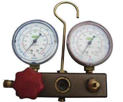
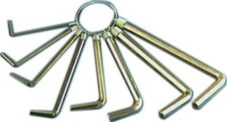
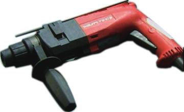
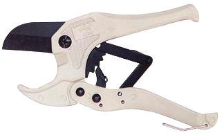
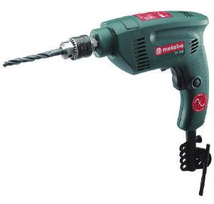
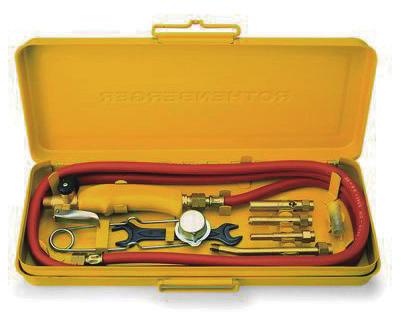
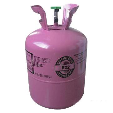
33 Service Manual Main Tools for 1. Measuring tape 2. Screw driver 3. Impact drill, drill head, electric drill Electroprobe 5. Universal meter 6. Torque wrench, open-end wrench, inner hexagon spanner 7. Electronic leakage detector 8. Vacuum pump 9. Pressure meter 10. Pipe pliers, pipe cutter 11. Pipe expander, pipe bender 12. Soldering appliance, refrigerant container
34 8. Installation 8.1 Installation procedures Start installation Preparation before installation Read the requirements for electric connection select installation location Prepare tools Select indoor unit installation location Select outdoor unit installation location Drill wall holes Connect pipes of indoor unit and drainage pipe Connect wires of indoor unit Install the support of outdoor unit (select it according to the actual situation) Fix outdoor unit Install drainage joint of outdoor unit (only for cooling and heating unit) Bind up pipes Connect pipes of outdoor unit Make the bound pipes pass through the wall hole and then connect outdoor unit Connect wires of outdoor unit eaten the pipes Vacuum pumping and leakage detection Check after installation and test operation Finish installation ote: this flow is only for reference; please find the more detailed installation steps in this section. 31
35 8.2 Installation Parts-checking o. ame o. ame 1 Indoor unit 7 Sealing gum 2 Outdoor unit 8 Wrapping tape 3 Connection pipe 9 Support of outdoor unit 4 Drainage pipe 10 Fixing screw 5 Connecting Drainage plug(cooling 11 cable(power cord) and heating unit) 6 Wall pipe 12 Owner s manual, remote controller ote: 1.Please contact the local agent for installation. 2.Don't use unqualified power cord. 8.3 Selection of Installation Location Basic requirement: Installing the unit in the following places may cause malfunction. If it is unavoidable, please consult the local dealer: 1.The place with strong heat sources, vapors, flammable or explosive gas, or volatile objects spread in the air. 2.The place with high-frequency devices (such as welding machine, medical equipment). 3.The place near coast area. 4.The place with oil or fumes in the air. in the air. 5.The place with sulfureted gas. 6.Other places with special circumstances. Indoor unit: 1. Avoid installing the indoor unit in a place where generated or leaked inflammable gas will stay. 2. Avoid installing the indoor unit in a moist place or in a place where oil may be splashed on the unit. 3. Select a location where outlet air may reach each corner of the room. 4. Select a location where connection pipe can be led to outdoor conveniently. 5. Select a location where air inlet and outlet won't be blocked. 6. Select a location with least affection of outdoor air. 7. Select a location with firm and flat floor. 8. Retain sufficient space for maintenance and installation. 9. Ensure the installation meets the requirement of installation dimension diagram. 10.Keep it away from fluorescent lamp. Outdoor Unit: 1. Select a location where the ise and outflow air emitted by the outdoor unit will t affect neighborhood. 2. The location should be well ventilated and dry, in which the outdoor unit won't be exposed directly to sunlight or strong wind. 3. The location should be able to withstand the weight of outdoor unit. 4. Make sure that the installation follows the requirement of installation dimension diagram. 5. Select a location which is out of reach for children and far away from animals or plants. If it is unavoidable, please add fence for safety purpose. 6. The height difference between indoor unit and outdoor unit should be within 5m. The length of connection pipe should be within 10m. 8.4 Precautions of Connecting Pipe The connection pipe and drainage pipe should be insulated to avoid water drop-ping due to condensation. 1. Both the indoor side and outdoor side adopt connection of expanding port. The connection pipe is as shown in the figure, used for connecting indoor unit and outdoor unit. 2. When connecting the big connection pipe and small connection pipe with the indoor unit, the big connection pipe and small connection pipe should be misaligned and the small connection pipe should be 100mm longer than big connection pipe. indoor unit connection of expanding port ote: Do t bend the flexible pipe for more than three times. Do insulation to all connection part of port-expanded pipe and connection pipe. (as shown in the figure) 3. The cut off valve of outdoor unit shall be closed completely. For each connection, screw off the screw cap at the cut-off valve and then connect the port-expanded pipe immediately (in 5min). If the screw cap at the cut off valve has been placed for a long time, dust, moisture and other sundries may get into the pipe, which will cause malfunction. band insulation cotton flexible pipe outdoor unit otices of flexible pipe: 1. The flexible pipe should be applied in the indoor side. 2. The bended angel shall t exceed The bended part shall be located in the pipe center. Bigger bended radius will be better. 4. Do t bend the flexible pipe for more than three times. bend the pipe with your thumb minimum radius is 100mm Situation of bending thinwalled pipe: 1. When bending the pipe, cut off the needed recess at the bended part of insulation pipe and then expose the pipe (wrap it with sealing tape after bending). 2. The pipe bended radius should be big in order to avoid damage. 3. Use pipe bender for the compact pipe bending. 32
36 method of unbinding coil make the pipe end straight Adopt cooper pipe sold in the market: The cut-off valve of outdoor unit shall be closed completely. After the connection is connected with the indoor unit and outdoor unit, perform discharge from the maintenance port of low pressure cut-off valve at outdoor unit. After discharging, screw up the nut at maintenance port. After finishing the three points mentioned above: The valve rod of outdoor cut-off valve should be opened completely to ensure smoothness of connection pipe between indoor unit and outdoor unit. electric coil (prevent water from getting into the electric box) seal the wall hole with sealing gum oil return bend watertight bend (prevent rain from getting into the indoor side) ote: When the outdoor unit is installed higher than the indoor unit, an oil return bend must be adopted. 8.5 Electric Connection Requirement Safety Precaution: 1. Must follow the electric safety regulations when installing the unit. 2. According to the local safety regulations, use qualified power supply circuit and air switch. 3. The air switch must have the functions of magnetic tripping and heat tripping in order to prevent short circuit or overload. Please install the air switch with suitable capacity according to the sheet below. Model 24K Capacity of air switch 25A 4. Make sure the power supply matches with the requirement of air conditioner. Unstable power supply or incorrect wiring may result in electric shock, fire hazard or malfunction. Please install proper power supply cables before using the air conditioner. 5. Properly connect the live wire, neutral wire and grounding wire of power socket. 6. Be sure to cut off the power supply before proceeding any work related to electric safety. 7. Do t put through the power before finishing installation. Grounding requirement: 1. The air conditioner is first class electric appliance. It must be properly grounded with specialized grounding device by a professional. Please make sure it is always grounded effectively, otherwise it may cause electric shock. 2. The yellow-green wire in air conditioner is grounding wire, which can't be used for other purposes. 3. The grounding resistance should comply with national electric safety regulations. Pay attention to the following items when connecting wires: 1. Please do the wiring according to the wiring diagram. The screws must be tightly fastened, the slippery screws must be changed, the tapping screw cant be used for electric wiring. 2. Use the cables provided with the unit. Do t replace the cables or change the length or terminal of cable. If a change is needed, please contact appointed maintenance center. 3. After the electric installation completed, make sure to use wire clamp to fix the power cord, power supply connection wire and signal wire tightly, and ensure that there is eugh space in the fix position and each connection terminals of the lead wires. 4. Please use about a half kilogram of force to check whether each lead wire is installed well. When checking the air connector, please enclasp it, and check each lead wire of which is connecting with the connector. 5. is the symbol of grounding; it detes that the yellowgreen wire only can be connected with the place with the symbol. 6. For the power cord which is without the plug, you cant connect the plug for using. 7. The electric connection of indoor and outdoor should t be affected by the stretch and bending. 8. Specialized circuit must be used for power supply. 9. Please do the wiring according to the wiring diagram sticking on the unit. 10. The primary coil of control circuit transformer shall be connected to the power supply of 220V. Detail satiation please refer to the wiring diagram. 11. For the floor standing type air conditioner using three phase power supply, the phases shall be connected properly. If the phases are connected wrongly or phase reverse occurs, the protector in the control circuit will take protection and the compressor can t start up. In this case, please cut off the power supply and exchange the connection of any two phase wires, then the unit will operate rmally. Simple installation diagram, please refer to the wiring diagram for details. outdoor unit power supply circuit breaker (air switch) power cord power connection wire indoor unit grounding 33
37 Service Manual Grounding requirements: The air conditioner is first class electric appliance. Please take reliable grounding measure. The yellow-green wire in the air conditioner is grounding wire. Do t use it for other purposes or cut it off. Do t fix it by the tapping screw. Otherwise, it may cause the electric shock. The grounding resistance should comply with national electric safety regulations. The power supply must be reliably grounded. Please do t connect the grounding wire to the following places: 1.Water pipe; 2.Gas pipe; 3.Drainage pipe; 4.The place where is unreliable suggested by the professional. Others: 1. All electric work must be performed by the qualified person according to local regulations and the instructions given in this manual. 2. The connection way between air conditioner and power cord, and the connection way among independent elements, please refer to the wiring diagram on the unit. 3. The model and rated value of fuse, please refer to the printing on corresponding controller or fuse sleeve. Step one: Installation of drainage pipe and connection pipe Remove the rear cover during piping and wiring. 1. Remove the screws fixing rear cover to remove the rear cover. 2. Please use the attached accessories during piping and wiring at the back. 3. According to the detail installation position of indoor unit, pull out the winding pipe(see fig.a) of indoor unit from the case(see fig.b); connect with the connection pipe and then bind the connection pipe and drainage pipe together(see fig.c). 4. Select left or right winding pipe according to the relative position of wall hole and the unit. 5. Cut the left or right baiting of rear cover according to direction of winding pipe and then assemble the rear cover. 6. Pack the indoor part of drainage pipe with insulating material (the thickness of the insulating material should be at least 9mm). The drainage pipe should be installed with an inclined angle from inside to outside for the condensation water to drain out conveniently. 7. Well pack the connection pipes and then place the indoor unit near the wall. screw drainage pipe rear cover connection pipe evaporator (Please refer to the actual product) 8.6 Installation of Indoor Unit fig.a fig.b fig.c At least 30cm Space to the ceiling Installation dimension diagram of indoor unit ote: Use adhesive plaster at drainage pipe and leave an inclined angle during installation of drainage pipe. Do t bind the black rubber tube with connection pipe and drainage pipe. h ot et ac Sp st A a t le n tio uc str b eo m 0c 20 Space to the wall ever upward inclined adhesive plaster At least 15cm water outlet pipe of indoor unit drainage pipe downward inclined water leakage accumulated condensation water air head of drainage pipe is in water canal water leakage 34 water leakage
38 Service Manual 8. Unfold the connection pipe, bend it according to the length needed, remove the screw cap on indoor unit pipe, match the connection pipe with the center of indoor unit pipe and then screw up the nut. (1) Hex nut diameter(mm) Φ6(1/4") Φ9.52(3/8") Φ12(1/2") Φ16(5/8") Φ19(3/4") Tightening torque(.m) 15~20 30~40 45~55 60~65 70~75 conical nut connection pipe wrench conical nut Moment wrench connection pipe indoor unit pipe Step two: Wiring of indoor unit 1. Press the rubber screw cover at the lower left corner of front door and then remove the screw. 2. Press the right side of front door with your right hand, push it rightwards and then pull the front door outwards with your left hand. 3. Remove the screw of support plate and then remove the support plate. Remove the screws fixing the electric box cover to remove the electric box cover. 4. Thread the power connection wire through the cable cross hole from the back. 5. Well connect the wire according to wiring diagram. 6. Fix the protecting cover section of power connection wire at the groove of wire clamp and then screw up the fixing screw to fix the connection wire firmly. 7. Power core and power connection wire should be fixed in the big groove of press clamp on the left. 8. Fix the electric box cover properly with sufficient screw. 9. Clamp the upper and lower shafts of door plate into the sliding groove; press the right side of front door with your right hand to push it rightwards; make the left side of front close to the chassis with your left hand; make the front slide leftwards until rest; screw up the screw and then cover the rubber screw cover. support plate screw 3 blue black brown Moment of screwing up: indoor unit pipe 2 Crimping clip wiring board yellowgreen Outdoor unit connection ote: Please contact the maintenance center for ather connection wire with adequate length if the present one is t long eugh. Correctly connect the wires. Well screw up the screws fixing terminals and connection wirings. The wirings should be properly fixed. Incorrect wiring connection of grounding wire may lead to electric shock. Well fix the electric box cover with sufficient screw. Improper assembly of electric box cover may cause fire hazard or electric shock. Step three: Installation of rear cover 1. Bind the connection pipe, connection wire and drainage pipe together with binder. Fix some positions for convenient binding Do t bind too tightly. Leave the joint of connection pipe for leakage test. Kck down the sub-small hole for 24 unit when cutting the baiting. 2. According to installation position, cut one of the baitings, thread the packed pipe and wire through the baiting hole. 3. Assemble the rear case. connection pipe drainage pipe binder connection pipe binder drainage pipe connection wire connection pipe, connection wire and drainage pipe rear cover baiting screw 35
39 Service Manual Step two: Pipe connection of outdoor unit Fix the outdoor unit on the selected position 1. Match the flared port of connection pipe to the valve, and then tighten them with hand. 2. Tighten them with torque wrench. 8.7 Installation of Outdoor Unit Installation dimension diagram of outdoor unit At least 50cm Space to the covering let m r in 0c t1 s lea At Ai At least 10cm Space to the obstruction e ac Sp At he t to st lea ob At least 50cm on cti u str Space to the obstruction cm 2 00 ote: Welding the pipes when lengthening the connection pipe. Step three: Connect outdoor electric wire 1. Remove the handle of outdoor unit. 2. Remove the wire clamp; connect the power connection to the wiring terminal and then fix it. The wire distribution must be in accordance with the indoor unit. 3. Fix the power connection wire with wire binder. 4. Make sure the wire is fixed properly. 5. Assemble the handle of outdoor unit. B Remove the screw to remove the big handle A A(cm) 61.0 wiring board grounding position fix screw Installation dimension of ODU B(cm) Models K Step one: Open piping hole 1. Confirm the position of pipe hole and drill a hole inclined to outside. 2. Assemble wall pipe to protect the piping and cable. 3. The distance between center of wall hole and bottom of air conditioner should be more than 22cm. The distance between the highest position of wall hole and the bottom of air conditioner should be more than 27cm (If the height of wall hole doesn t meet the requirement, please drill hole again to avoid water leakage.) indoor wall pipe indoor outdoor sealing gum sealing gum (1) 2 yellowgreen 3 L blue black brown brown blue (black) L Indoor unit connection yellowgreen POWER Step four: Drainage of outdoor unit condensation water (t applicable for cooling only unit) When the unit is heating, the condensation water formed in the outdoor unit can be drained out properly through the drainage hose.installation: Install the outdoor drainage joint in the Φ25 hole on the chassis as shown in the figure. Then connect the drainage pipe to the drainage port, so that the condensation water formed in the outdoor unit can be drained out to a proper place. 50cm wall pipe outdoor wire binder chassis of outdoor unit drainage joint of outdoor unit 36
40 8.8 Vacuum Pumping and Leak Detection Use vacuum pump 1. Remove the valve caps on the liquid valve and gas valve and the nut of refrigerant charging vent. 2. Connect the charging hose of piezometer to the refrigerant charging vent of gas valve and then connect the other charging hose to the vacuum pump. 3. Open the piezometer completely and operate for 10-15min to check if the pressure of piezometer remains in -0.1MPa. 4. Close the vacuum pump and maintain this status for 1-2min to check if the pressure of piezometer remains in -0.1MPa. If the pressure decreases, there may be leakage. 5. Remove the piezometer, open the valve core of liquid valve and gas valve completely with inner hexagon spanner. 6. Tighten the screw caps of valves and refrigerant charging vent. liquid valve refrigerant charging vent valve cap nut of refrigerant charging vent gas valve valve cap piezometer Lo Hi vacuum pump inner hexagonspanner close open Leakage detection 1. With leakage detector Check if there is leakage with leakage detector. 2. With soap water: If leakage detector is t available, please use soap water for leakage detection. Apply soap water at the suspected position and keep the soap water for more than 3min. If there are air bubbles coming out of this position, there's a leakage. Leakage detection point of outdoor unit 8.9 Check after Installation and Test Operation 1. Check after Installation Check according to the following requirement after finishing installation. O. Items to be checked Possible malfunction 1 Has the unit been The unit may drop, shake or installed firmly? emit ise. 2 Have you done the It may cause insufficient cooling refrigerant leakage test? (heating) capacity. 3 Is heat insulation of It may cause condensation and pipeline sufficient? water dripping. 4 Is water drained well? It may cause condensation and water dripping. Is the voltage of power 5 supply according to the It may cause malfunction or voltage marked on the damage the parts. nameplate? Is electric wiring and pipeline installed correctly? Is the unit grounded securely? Does the power cord follow the specification? Is there any obstruction It may cause malfunction or damage the parts. It may cause electric leakage. It may cause malfunction or damage the parts. It may cause insufficient cooling in air inlet and air outlet? (heating) capacity. The dust and sundries caused It may cause malfunction or during installation are damaging the parts. removed? The gas valve and liquid It may cause insufficient cooling valve of connection pipe (heating) capacity. are open completely? Is the inlet and outlet of piping hole been covered? It may cause insufficient cooling (heating) capacity or waster eletricity. 2. Test operation (1) Preparation of test operation The client approves the air conditioner installation. Specify the important tes for air conditioner to the client. (2) Method of test operation Put through the power, press O/OFF button on the remote controller to start operation.press MODE button to select AUTO, COOL, DR, FA and HEAT to check whether the operation is rmal or t.if the ambient temperature is lower than 16ºC, the air conditioner can t start cooling Installation of anti-tilting Chain Leakage detection point of indoor unit In order to prevent tilting due to an accident, please install the anti-tilting chain. Installation steps: 1. Remove the screw in the anti-tilting hole at the top cover of indoor unit (see Figure 1). 2. Take out the anti-tilting chain from the accessories; put it into the anti-tilting hole and then fix it with screw (see Figure 2). 3. Fix the other end of anti-tilting chain on the wall with screw(st4.2x38) (see Figure 2). 37
41 connect this end wih the wall and fix it with screw remove the screw at top cover put this end into the anti-tilting hole anti-tilting hole anti-tilting hole wall indoor unit Figure 1 Figure 2 Actual product may be different from above graphics, please refer to actual products. 38
42 9.Troubleshooting 9.1 Judgement by Flashing LED of Indoor o. Malfunction ame Display Method of Indoor Unit Dual-8 Code Display A/C status Possible Reasons 1 High pressure protection of system E1 Cooling: Compressor stops and indoor fan operates. Heating: All the loads are stopped. Overpressure of AC system 2 Antifreezing protection E2 Cooling: Compressor stops and indoor fan operates. Heating: All the loads are stopped. Indoor tube temperature is too low under cooling mode 3 High discharge temperature protection of compressor E4 Cooling: Compressor stops and indoor fan operates. Heating: All the loads are stopped. Discharge temperature is too high. 4 Overcurrent protection E5 Cooling: Compressor stops and indoor fan operates. Heating: All the loads are stopped. Unit s overall current is too large. 5 Communication Malfunction E6 Cooling: Compressor stops and indoor fan operates. Heating: All the loads are stopped. Bad communication of outdoors Bad communication between main board of indoor unit and display board (display E6 and indoor temp) 6 High temperature resistant protection E8 Cooling: Compressor stops and indoor fan operates. Heating: All the loads are stopped. Indoor tube temperature is too high under heating mode Discharge temperature sensor of outdoor unit is t inserted in copper pipe o feedback on motor of indoor unit Indoor ambient temperature sensor is open/short circuited Indoor evaporator temperature sensor is open/short circuited Outdoor ambient temperature sensor is open/short circuited U8 H6 F1 F2 F3 Cooling: Compressor stops and indoor fan operates. Heating: All the loads are stopped. Cooling: Compressor stops and indoor fan operates. Heating: All the loads are stopped. Cooling: Compressor stops and indoor fan operates. Heating: All the loads are stopped Cooling: Compressor stops and indoor fan operates. Heating: All the loads are stopped. Discharge temperature sensor of outdoor unit is t inserted in copper pipe Open circuit or short circuit of indoor ambient temperature sensor Open circuit or short circuit of indoor evaporator Open circuit or short circuit of outdoor ambient temperature sensor 39
43 o Malfunction ame Outdoor condenser temperature sensor is open/short circuited Outdoor discharge temperature sensor is open/short circuited Limit/decrease frequency due to overload Display Method of Indoor Unit Dual-8 Code Display F4 F5 F6 A/C status Cooling: Compressor stops and indoor fan operates. Heating: All the loads are stopped. Cooling: Compressor stops and indoor fan operates. Heating: All the loads are stopped. Loads are running rmally. Compressor operating frequency is decreased. Open-circuit or short-circuit of outdoor condenser temperature sensor Open-circuit or short-circuit of outdoor discharge temperature sensor Cooling outer tube temperature is too high. Heating inner tube temperature is too high. Possible Reasons 15 Decrease frequency due to overcurrent F8 Loads are running rmally. Compressor operating frequency is decreased. Unit s overall current is too large. 16 Decrease frequency due to high air discharge F9 Loads are running rmally. Compressor operating frequency is decreased. Discharge temperature is too high. 17 Rotary casing stuck protection FC All the loads are stopped. The rotary casing is stuck when rotating Limit/decrease frequency due to antifreezing Decrease frequency due to high temperature resistant during heating operation FH H0 20 Defrosting H Static dedusting protection Overload protection for compressor System is abrmal H2 H3 H4 24 IPM protection H5 Loads are running rmally. Compressor operating frequency is decreased. Loads are running rmally. Compressor operating frequency is decreased. A rmal operation mode under heating mode. Both compressor and indoor fan stop. Cooling: Compressor stops and indoor fan operates. Heating: All the loads are stopped. Cooling: Compressor stops and indoor fan operates. Heating: All the loads are stopped. Cooling: Compressor stops and indoor fan operates. Heating: All the loads are stopped. Cooling inner tube temperature is too low. Heating inner tube temperature is too high. Too much frost on outdoor condenser. Compressor temperature is too high. Outdoor tube temperature is too high under cooling mode; Indoor tube temperature is too high under heating mode Compressor s current is too large 40
44 o. Malfunction ame Display Method of Indoor Unit A/C status Possible Reasons Dual-8 Code Display 25 Module high temperature protection P8 Cooling: Compressor stops and indoor fan operates. Heating: All the loads are stopped. Module temperature is too high Malfunction of module temperature sensor circuit Desynchronizing of compressor P7 H7 Cooling: Compressor stops and indoor fan operates. Heating: All the loads are stopped. Cooling: Compressor stops and indoor fan operates. Heating: All the loads arestopped. Open-circuit or short-circuit of module temperature thermal resistance Compressor n-synchronism 28 Overcurrent protection of phase current for compressor P5 Cooling: Compressor stops and indoor fan operates. Heating: All the loads are stopped. Compressor s current is too large 29 Malfunction of phase current detection circuit for compressor U1 Cooling: Compressor stops and indoor fan operates. Heating: All the loads are stopped. Compressor current sensing circuit is t effective. 30 Failure start-up LC 31 PFC protection HC Cooling: Compressor stops and indoor fan operates. Heating: All the loads are stopped. Cooling: Compressor stops and indoor fan operates. Heating: All the loads are stopped. Compressor startup is defective. PFC over-current protection 32 EEPROM malfunction EE Cooling: Compressor stops and indoor fan operates. Heating: All the loads are stopped. Outdoor unit reads EEPROM data wrongly. 33 Charging malfunction of capacitor PU Cooling: Compressor stops and indoor fan operates. Heating: All the loads are stopped. Electrolytic capacitor charge up circuit is disabled. 34 Malfunction of voltage dropping for DC bus-bar U3 Cooling: Compressor stops and indoor fan operates. Heating: All the loads are stopped. Alternating current decreases a lot instantly. 35 Voltage of DC bus-bar is too low PL Cooling: Compressor stops and indoor fan operates. Heating: All the loads arestopped. DC voltage after power rectification is too high. 36 Voltage for DC bus-bar is too high PH Cooling: Compressor stops and indoor fan operates. Heating: All the loads are stopped. DC voltage after power rectification is too high. 37 Limit/decrease frequency due to high temperature of module EU Loads are running rmally. Compressor operating frequency is decreased. Module temperature is too high. 38 Unit's overall current sensing error U5 Cooling: Compressor stops and indoor fan operates. Heating: All the loads are stopped. Unit s overall current sensing circuit is t effective. 41
45 o. 39 Malfunction ame The four-way valve is abrmal Display Method of Indoor Unit Dual-8 Code Display U7 A/C status Cooling: Compressor stops and indoor fan operates. Heating: All the loads are stopped. Possible Reasons 4-way valve doesn t change direction under heating mode. 40 Outdoor unit zero cross error Cooling: Compressor stops and indoor fan operates. Heating: All the loads are stopped. Outdoor unit sensing AC power zero cross circuit is ineffective Outdoor DC fan motor malfunction Selection port electrical level is abrmal. PFC current offset voltage is wrong. Pipe covering middle tube temperature sensor error Humidity sensor error Communication error between indoor unit and check board Radio frequency module error Voltage is too high Outdoor fan phase loss Outdoor fan nsynchronism Phase current protection frequency limit/ frequency decrease Outdoor ambient temperature is abrmal. Fan current sensing circuit error Peak current frequency limit or decrease Fluorine shortage protection, refrigerant circulation cut-off protection. L3 HC F4 Cooling: Compressor stops and indoor fan operates. Heating: All the loads are stopped. Cooling: Compressor stops and indoor fan operates. Heating: All the loads are stopped. Cooling: Compressor stops and indoor fan operates. Heating: All the loads are stopped. Cooling: Compressor stops and indoor fan operates. Heating: All the loads are stopped. Outdoor fan error. Model s selection port electrical level is abrmal. PFC current offset voltage is wrong. Pipe covering middle tube temperature sensor error L1 Air conditioner can work rmally. Humidity sensor error JF rf oe F0 Cooling: Compressor stops and indoor fan operates. Heating: All the loads are stopped. Cooling: Compressor stops and indoor fan operates. Heating: All the loads are stopped. Cooling: Compressor stops and indoor fan operates. Heating: All the loads are stopped. Cooling: Compressor stops and indoor fan operates. Heating: All the loads are stopped. Cooling: Compressor stops and indoor fan operates. Heating: All the loads are stopped. Loads are running rmally. Compressor operating frequency is decreased. Cooling: Compressor stops and indoor fan operates. Heating: All the loads are stopped. Communication error between indoor unit and check board Radio frequency module error DC voltage after power rectification is too high. Outdoor fan power phase loss. Outdoor fan n-synchronism Compressor phase current is too large. Outdoor ambient temperature is too high or too low. Cooling: Compressor stops and Fan current sensing circuit indoor fan operates. Heating: All the loads are is abrmal. stopped. Loads are running rmally. Compressor operating frequency is decreased. Cooling: Compressor stops and indoor fan operates. Heating: All the loads are stopped. PFC peak current is too large. Air conditioner is short of fluorine. Valve doesn t open. System is blocked. 42
46 9.2 How to Check Simply the Main Part of Indoor 1. Malfunction of Temperature Sensor F1, F2 Troubleshooting for F1,F2 malfunction Is the wiring terminal between the temperature sensor and the controller loosened or poorly contacted? Insert the temperature sensor tightly Is malfunction eliminated Is there short circuit due to trip - over of the parts? Make the parts upright Is malfunction eliminated Is the temperature sensor rmal according to the Resistance Table? Replace it with a temperature sensor with the same model Is malfunction removed Replace the mainboard with the same model. End 43
47 2. Malfunction of Blocked Protection of IDU Fan Motor H6 Troubleshooting for H6 malfunction Stir the blade with a tool to see whether the blade rotates smoothly Tighten the screw; reassemble the blade, motor and shaft bearing rubber base sub-assy to make sure there is foreign object between them Is malfunction eliminated Check if the connection of PG motor feedback terminal is firm. Insert the control terminal of PG motor tightly Is malfunction eliminated Check if the connection of PG motor control terminal is firm. Reinstall the blade and motor correctly Is malfunction eliminated Turn on the unit again; measure whether the output voltage on control terminal for PG motor is more than 50V within 1 min after the louvers are opened Is the motor started up Measure the voltage of this foot to neutral wire on the mainboard Replace PG motor Is malfunction eliminated Replace the mainboard with the same model. End 44
48 3. Malfunction of Protection of Jumper Cap C5 Troubleshooting for C5 malfunction Is there jumper cap on the mainboard? Assemble the jumper cap with the same model Is malfunction eliminated Appearance of the jumper cap Is the jumper cap inserted correctly and tightly? Insert the jumper cap tightly Is malfunction eliminated Replace the jumper cap withthe same model Is malfunction eliminated Replace the mainboard with the same model. End 45
49 4. Malfunction of Zero-crossing Inspection Circuit Malfunction of the IDU Fan Motor U8 Troubleshooting for U8 malfunction Re-energize1 minute after de-erergization U8 is still displayed es o The unit returns to rmal. Conclusion:U8 is displayed due to instant energization afte deenergization while the capacitor discharges slowly. The zero-cross detection circuit of the mainboard is defined abrmal.replace the mainboard with the same model End 46
50 5. Malfunction of Protection of High Pressure Protection (E1) Start Are the display panel and main board connected tightly? Connect the display panel with the main board well Malfunction is eliminated. Are the OVC terminal on the main board connected well with the high pressure switch on the complete unit? Connect the OVC terminal on the main board with the high pressure switch on the complete unit well Malfunction is eliminated. Is the wiring of high pressure switch loosened? Is the high pressure switch broken or poorly contacted? If the wire of high pressure switch is loosened, please connect the wires according to the circuit diagram. If the high pressure switch is broken or poorly contacted, please replace it. Malfunction is eliminated. Is the refrigerant superabundant? Adjust the volume of refrigerant according to the requirement of the system Malfunction is eliminated. Is there poor heat exchange? (Including filth blockage of heat exchanger and bad radiating environment ); Adjust the unit to improve the heat exchange of unit Malfunction is eliminated. Is the ambient temperature too high? (If it is a 3-phase unit, high pressure protection may be caused by over current protection due to this) Decrease the ambient temperature Malfunction is eliminated. Is the supply voltage rmal? (If it is a 3-phase unit, high pressure protection may be caused by overcurrent protection due to this) The rmal fluctuation is within 10% of the rated voltage on the nameplate Malfunction is eliminated. Are the air intake and air discharge at indoor / outdoor heat exchanger smooth? Adjust the system to make the air intake and air discharge of indoor and outdoor heat exchangers smooth Malfunction is eliminated. Is there filth blockage on the filter or on the heat exchanger fins of indoor / outdoor unit? Remove the blockage. Malfunction is eliminated. Is there blockage inside the pipeline of the system Remove the blockage inside the pipeline of the system Malfunction is removed. Are the gas valve and liquid valve for outdoor unit opened completely? Open the outdoor gas valve and liquid valve completely Malfunction is eliminated. Is the high pressure signal at high level? Check the system further Malfunction is eliminated. Replace the controller End 47
51 6. Malfunction of Protection of Freeze Protection (E2) Start Is there poor air return in the indoor unit? Solve the problem of system. Malfunction is eliminated. Is the fan speed abrmal? Solve the problem of speed. Malfunction is eliminated. Is the evaporator dirty? Clean the evaporator Problem is solved. System is rmal, but the indoor tube temperature sensor is abrmal. Replace the temperature sensor Problem is solved. Replace the controller End 48
52 7. Malfunction of Protection of High Discharge Temperature Protection (E4) 49
53 8. Malfunction of Overcurrent Protection E5 Troubleshooting for E5 malfunction Is the supply voltage unstable with big fluctuation? ormal fluctuation is within 10 % of the rated voltage on the nameplate Malfunction is eliminated Is the supply voltage too low with overload? Adjust the supply voltage to maintain it within rmal range Malfunction is eliminated Is the indoor / outdoor heat exchanger too dirty,or are the air inlet and outlet blocked? Clean the indoor and outdoor heat exchangers and remove the blockage of air inlet and outlet Malfunction is eliminated The fan is abrmal? Fan speed is too low or fan doesn t rotate Check the motor and reinstall the motor to have the fan run rmally Malfunction is eliminated Measure the current of live wireon the main board with a clamp ampere meter. Is the current higher than the value of the overcurrent protection? Replace the mainboard with the same model Malfunction is eliminated Is there blockage inside the system? (Filth blockage, ice plug, greasy blockage, the -valve hasn t been opened completely) Flush the heat exchangers with high pressure nitrogen Malfunction is eliminated Is the compressor running abrmally? Is there abrmal sound or oil leakage; is the temperature of the shell too high, etc.? Replace the mainboard with the same model Malfunction is eliminated Replace the mainboard with the same model End 50
54 9. Malfunction of Communication E6 Start Cut off power supply. Check if connection line of IDU and ODU and the wire inside electric box are correctly connected. Correct connection? Connect the line according to wiring diagram. Malfunction eliminated? Main board matches with display board? Main board of IDU matches with that of ODU? Match correctly according to product specification Malfunction eliminated? Communication cord is damaged? Replace communication cord Malfunction eliminated? Replace IDU's main board Malfunction eliminated? Replace ODU's main board. End 51
55 9.3 How to Check Simply the Main Part of outdoor Discharging method (1) Remove the inverter cover(outdoor Unit) Inverter cover P.C.board (Soldered surface) (2)As shown below,connect the discharge resistance(approx.100ω20w)or plug of the sold ering iron to voltage between + - terminals of the electrolytic capacitor on PC Board for 30s, and then peformedischarging. OTE: A large-capacity electrolytic capacitor is used in the outdoor unit controller(inverter).therefore,if the power supply is turned off,charge(charging voltage DC280V to 380V)remains and disc harging takes a lot of time.. After turning off the power source,if touching the charging section before discharging, an electrical shock may be caused. Discharge the electrol ytic capacitor completely by using soldering iron,etc. 52
56 1. Capacitor Charging Malfunction (Outdoor unit malfunction) Outdoor unit malfunction indicator status D5 D6 D16 D30 Main detection point: Detect if the voltage of L and terminal of wiring board is between 210AC-240AC by alternating voltage meter; Is reactor (L) well connected? Is connection wire loosened or pull-out? Is reactor (L) damaged? Malfunction diagsis process: Turn on the unit and wait 1 minute Use DC voltmeter to measure the voltage on the two ends of electrolytic capacitor Voltage higher than 200V? Fault with the voltage testing circuit on control panel AP1 Replace the control panel AP1 Measure the AC voltage between terminal L and on wiring board XT(power supply) Voltage within 210VAC~250VAC? Shut down the power and repair the power supply to restore the range 210VAC~250VAC power on and restart the unit If the fault is eliminated? Shut down the power and wait 20n muties; or use DC voltmeter to measure the voltage on the two ends of capacitor (test3), until the voltage is lower than 20V Check the connection of reactor (L in the Electrical Wiring Diagram) If the wiring of reactor L is rmal? Connect the reactor Laccording to Electrical Wiring Diagram correctly Re-energize and turn on the unit If the fault is eliminated? Replace the control panel AP1 End 53
57 2. IPM Protection, Desynchronizing Malfunction, Phase Current of Compressor is Overcurrent (Outdoor unit malfunction) Outdoor unit malfunction indicator status Malfunction D5 D6 D16 D30 IPM protection Desynchronizing malfunction Compressor overcurrent Main detection point: If control board AP1 and compressor COMP is well connected? If they are loosened? If the connection sequence is correct? Is voltage input in the rmal range (Test the voltage between L, of wiring board XT by DC voltage meter)? If coil resistance of compressor is rmal? Is compressor coil insulating to copper pipe well? If the work load of unit is heavy? If radiating of unit is well? If the refrigerant charging is appropriate? Malfunction diagsis process: 54
58 Energize and switch on IPM protection occurs after the machine has run for a period of time? Use AC voltmeter to measure the voltage between terminal L and on the wiring board XT) If the voltage between terminal L and on wiring board XT is within 210VAC~250VAC? Check the supply voltage and restore it to 210VAC~250VAC Voltage between the two ends of celectrolytic capacitor (test3) is higher than 250V Restart the unit. Before protection occurs,use DC voltmeter to measure the voltage between the two ends of electrolytic capacitor on control panel AP1 (test3) If the unit can work rmally? Please confirm: 1. If the indoor and outdoor heat exchangers are dirty? If they are obstructed by other objects which affect the heat exchange of indoor and outdoor unit. 2. If the indoor and outdoor fans are working rmally? 3. If the environment temperature is too high, resulting in that the system pressure is too high and exceeds the permissible range? 4. If the charge volume of refrigerant is too much, resulting in that the system pressure is too high? 5. Other conditions resulting in that the system pressure becomes too high. Stop the unit and disconnect the power supply. Then, check the connection of capacitor C2 according to Electrical Wiring Diagram. Remove the wires on the two ends of capacitor C2. Then, use capacitance meter to measure the capacitor C2. Verify as per the Parameters Sheet. If capacitor C2 is failed? The connection of capacitor C2 is loose. Stop the unit and disconnect the power supply. Wait 20 minutes, or use DC voltmeter to measure the voltage between the two ends of capacitor C2, until the voltage is lower than 20V Replace the capacitor C2. Then, energize and start the unit. Replace the control panel AP1 Reconnect the capacitor C2 according to Electrical Wiring Diagram. Then, Restart the unit. If the unit can work rmallv? Refer to the Electrical Wiring Diagram and check if the connection between AP1 and COMP is loose and if the connection order is correct. If there is any abrmality described above? Take corrective actions according to Technical Service Manual, and then energize and start the unit. If the unit can work rmally? Replace the control panel AP1 If the connection between AP1 and COMP is unsecure or the connectiorder is wrong? Connect the control panel AP1 and compressor COMP correctly according to the Electrical Wiring Diagram. Then, energize and start the unit. If the unit can work rmally? Use ohmmeter to measure the resistance between the three terminals on compressor COMP, and compare the measurements with the compressor resistance on Service Manual. If the resistance is rmal? Replace the compressor COMP Use ohmmeter to measure the resistance between the two terminals of compressor COMP and copper tube. Resistance higher than 500MΩ? Replace the control panel AP1 ED 55
59 3. Diagsis for High Temperature, Overload Protection (Check outdoor unit in cooling mode and check indoor unit in heating mode) Outdoor unit malfunction indicator status D5 D6 D16 D30 Main detection point: If the outdoor ambient temperature is in rmal range; If the indoor and outdoor fan is running rmally; If the radiating environment inside and outside the unit is well (including if the fan speed is too low)? If the tube temperature sensor of indoor and outdoor unit is rmal? Malfunction diagsis process: High temperature, overload protection If the outdoor ambient temperature is higher than 53 ºC in cooling mode?/if the ambient temperature of indoor and outdoor unit is too high? ormal protection, please use it after improving ambient temperature of indoor and outdoor unit If the radiating of outdoor and indoor unit is well? Improve the radiating environment of the unit If the indoor and outdoor fan work well? check if the tube temp sensor is rmal according to the resistance sheet(check outdoor tube temp in cooling mode, check indoor tube temp sensor in heating mode) 1. Check if fan terminal OFA is connected well 2. Test if the motors of indoor and outdoor unit are broken Replace fan capacitor C1 De-energize the unit and wait for 20min Is the tube temp sensor rmal? Replace outdoor fan Replace the control board(replace the outdoor control board in cooling mode, replace the indoor control board in heating mode) Replace the tube temperature sensor End 56
60 4. Diagsis for Failure Start up Malfunction (Outdoor unit malfunction) Outdoor unit malfunction indicator status D5 D6 D16 D30 Main detection point: If the compressor wiring is correct? If the stop time of compressor is eugh? If the compressor is damaged? If the refrigerant charging is too much? Malfunction diagsis process: Energize the unit and start it If the stop time of compressor is more than 3min? If the stop time is t eugh and the high and low pressure of system is t balance, please start it after 3min If the compressor wire COMP(UVW) is well connected and connection sequence is correct Improve the connection situation of control board AP1 and compressor COMP, connect it with wiring diagram If the refrigerant charging is too much? Does the unit start up rmally? Charge the refrigerant according to service manual Does the unit start up rmally? Replace control board AP1 If malfunction is removed? Replace the compressor End 57
61 5. Diagsis for Compressor Synchronism (Outdoor unit malfunction) Outdoor unit malfunction indicator status D5 D6 D16 D30 Main detection point: If the system pressure is over-high? If the working voltage is over-low? Malfunction diagsis process: Synchronism after energize the unit and start it Synchronism occurred during operation If the stop time of compressor is more than 3min If the outdoor fan works rmally? Check if the fan terminal OFA is connected well Replace fan capacitor C1 If the compressor wire COMP(UVW) is well connected, the connection sequence forwards to clockwise direction? If the radiating of unit is well? Improve the radiating of unit (clean heat exchanger and increase ventilation) Replace outdoor fan Connect wire well Replace control board AP1 Remove malfunction? Replace compressor If the input voltage of unit is rmal? If the refrigerant is too much? Replace control board AP1 Start to run until the power resume rmal voltage Charge the refrigerant with service manual Remove malfunction? End Replace compressor End 58
62 6. Diagsis for Overload and Discharge Malfunction (Outdoor unit malfunction) Outdoor unit malfunction indicator status Malfunction D5 D6 D16 D30 Overload Discharge Main detection point: If the electron expansion valve is connected well? Is the expansion valve damaged? If the refrigerant is leakage? If the overload protector is damaged? If the discharge temp sensor is damaged? Malfunction diagsis process: After the u nit de-energized for 20min If the overload protector SAT is well connected? Under ambient temperature, test the resistance of overload protector with ohmic meter, the resistance value<10000ω If the wiring terminal FA of electron expansion is well connected? Connect the wire well according to wiring disgram Check if the coil of electron expansion is installed on the valve rmally Replace overload protector SAT Check if the expansion valve is blocked Remove malfunction? Check refrigerant, if there is leakage, please refer to specification Remove malfunction? check if the discharge temp sensor is rmal according to the resistance sheet Replace discharge temp sensor Replace control board End 59
63 7. Communication Malfunction Outdoor unit malfunction indicator status D5 D6 D16 D30 Main detection point: Check if the connection wire and the built-in wiring of indoor and outdoor unit is connected well and damaged; If the communication circuit of indoor mainboard is damaged? If the communication circuit of outdoor mainboard (AP1) is damaged? Malfunction diagsis process: Start If the unit is operating rmally before malfunction Check connection wire of indoor and outdoor unit with circuit diagram Check if the controller connection wire inside indoor and outdoor electric box is loose Connection correct? Connectwire of indoor and outdoor unit according to circuit diagram If the connection wire is rmal? Check communication circuit of outdoor unit Connect wire of indoor and outdoor unit according to circuit diagram If the malfunction is removed? Problem of communication circuit Replace outdoor mainboard (AP1) If the malfunction is removed? If the malfunction is removed? Replace indoor mainboard End 60
64 9.4 Maintenance Method for ormal Malfunction 1. Air Conditioner Can't be Started Up Possible Causes Discriminating Method (Air conditioner Status) Troubleshooting o power supply, or poor connection for power plug Wrong wire connection between indoor unit and outdoor unit, or poor connection for wiring terminals 2. Poor Cooling (Heating) for Air Conditioner Possible Causes Discriminating Method (Air conditioner Status) Troubleshooting Set temperature is improper Observe the set temperature on remote controller Adjust the set temperature Rotation speed of the IDU fan motor is set too low Small wind blow Set the fan speed at high or medium Filter of indoor unit is blocked Check the filter to see it's blocked Clean the filter Check whether the installation postion is proper Installation position for indoor unit Adjust the installation position, and install the according to installation requirement for air and outdoor unit is improper rainproof and sunproof for outdoor unit conditioner Discharged air temperature during cooling is higher than rmal discharged wind temperature; Refrigerant is leaking Discharged air temperature during heating is Find out the leakage causes and deal with it. lower than rmal discharged wind temperature; Add refrigerant. Unit's pressure is much lower than regulated range Malfunction of 4-way valve Blow cold wind during heating Replace the 4-way valve Discharged air temperature during cooling is higher than rmal discharged wind temperature; Discharged air temperature during heating is Malfunction of capillary lower than rmal discharged wind temperature; Replace the capillary Unit't pressure is much lower than regulated range. If refrigerant isn t leaking, part of capillary is blocked Flow volume of valve is insufficient Malfunction of horizontal louver The pressure of valves is much lower than that stated in the specification Horizontal louver can t swing Malfunction of the IDU fan motor The IDU fan motor can t operate Malfunction of the ODU fan motor The ODU fan motor can't operate Malfunction of compressor 3. Horizontal Louver Can't Swing After energization, operation indicator isn t bright and the buzzer can't give out sound Under rmal power supply circumstances, operation indicator isn't bright after energization Compressor can't operate Confirm whether it's due to power failure. If, wait for power recovery. If t, check power supply circuit and make sure the power plug is connected well. Check the circuit according to circuit diagram and connect wires correctly. Make sure all wiring terminals are connected firmly Make sure the air conditioner is grounded reliably Make sure wires of air conditioner is connected After energization, room circuit breaker trips off at Electric leakage for air conditioner correctly once Check the wiring inside air conditioner. Check whether the insulation layer of power cord is damaged; if, place the power cord. Model selection for air switch is After energization, air switch trips off Select proper air switch improper Malfunction of remote controller After energization, operation indicator is bright, while display on remote controller or buttons have action. Replace batteries for remote controller Repair or replace remote controller Open the valve completely Refer to point 3 of maintenance method for details Refer to troubleshooting for H6 for maintenance method in details Refer to point 4 of maintenance method for details Refer to point 5 of maintenance method for details Possible Causes Discriminating Method (Air conditioner Status) Troubleshooting Wrong wire connection, or poor connection Check the wiring status according to circuit diagram Connect wires according to wiring diagram to make sure all wiring terminals are connected firmly Stepping motor is damaged Stepping motor can't operate Repair or replace stepping motor Main board is damaged Others are all rmal, while horizontal louver can't operate Replace the main board with the same model 61
65 4. ODU Fan Motor Can't Operate Possible causes Discriminating method (air conditioner status) Troubleshooting Wrong wire connection, or poor connection Capacity of the ODU fan motor is damaged Power voltage is a little low or high Motor of outdoor unit is damaged 5. Compressor Can't Operate Possible causes Discriminating method (air conditioner status) Troubleshooting Wrong wire connection, or poor connection 6. Air Conditioner is Leaking Check the wiring status according to circuit diagram Check the wiring status according to circuit diagram Connect wires according to wiring diagram to make sure all wiring terminals are connected firmly Measure the capacity of fan capacitor with an universal meter and find that the capacity is out of Replace the capacity of fan the deviation range indicated on the nameplate of fan capacitor. Use universal meter to measure the power supply Suggest to equip with voltage regulator voltage. The voltage is a little high or low When unit is on, cooling/heating performance Change compressor oil and refrigerant. If is bad and ODU compressor generates a lot of better, replace the compressor with a new one ise and heat. Connect wires according to wiring diagram to make sure all wiring terminals are connected firmly Measure the capacity of fan capacitor with an Capacity of compressor is universal meter and find that the capacity is out of Replace the compressor capacitor damaged the deviation range indicated on the nameplate of fan capacitor. Power voltage is a little low or Use universal meter to measure the power supply Suggest to equip with voltage regulator high voltage. The voltage is a little high or low Use universal meter to measure the resistance Coil of compressor is burnt out Repair or replace compressor between compressor terminals and it's 0 Cylinder of compressor is blocked Compressor can't operate Repair or replace compressor Possible causes Discriminating method (air conditioner status) Troubleshooting Drain pipe is blocked Water leaking from indoor unit Eliminate the foreign objects inside the drain pipe Drain pipe is broken Water leaking from drain pipe Replace drain pipe Wrapping is t tight Water leaking from the pipe connection place of indoor unit Wrap it again and bundle it tightly 7. Abrmal Sound and Vibration Possible causes Discriminating method (air conditioner status) Troubleshooting When turn on or turn off the unit, the panel and other parts will ormal phemen. Abrmal sound will There's the sound of "PAPA" expand and there's abrmal disappear after a few minutes. sound When turn on or turn off the unit, there's abrmal sound due ormal phemen. Abrmal sound will Water-running sound can be heard to flow of refrigerant inside air disappear after a few minutes. conditioner Foreign objects inside the indoor unit or there're parts touching together inside the indoor unit There's abrmal sound fro indoor unit Remove foreign objects. Adjust all parts' position of indoor unit, tighten screws and stick damping plaster between connected parts Foreign objects inside the outdoor Remove foreign objects. Adjust all parts' unit or there're parts touching together inside the outdoor unit There's abrmal sound fro outdoor unit position of outdoor unit, tighten screws and stick damping plaster between connected parts Short circuit inside the magnetic During heating, the way valve has abrmal coil electromagnetic sound Replace magnetic coil Abrmal shake of compressor Outdoor unit gives out abrmal sound Adjust the support foot mat of compressor, tighten the bolts Abrmal sound inside the compressor Abrmal sound inside the compressor If add too much refrigerant during maintenance, please reduce refrigerant properly. Replace compressor for other circumstances. 62
66 Service Manual 10. Exploded View and Parts List 10.1 Indoor Unit The component picture is only for reference; please refer to the actual product. 63
67 O. Description Part Code GVH24AK-K3DC8A/I Product Code CH Electric Box Insatallation Box PCB Retaining Plate Main Board Electric Box Cover Support plate (bearing) (bottom) (black) Bearing assy (plastic) Support plate (rotation) (black) Fan Motor Connecting plate Decorative plate (left) Reinforcement Board (left) Reinforcement Board (right) Decorative plate (right) Top combination Retaining Plate Air Outlet Panel P 1 18 Support frame Electric Box Fireproofing Cover Stepping Motor Air Scroll Cross Flow Fan Evaporator Assy Inching Switch Connected Board(Front Panel) Mounting bracket(motor) Decorative plate (mounting bracket) Front Panel Sub-assy (display) Display Module Decoration D 1 31 Cover(Top) Foam (top cover) Top cover (character) Switch Board Internal gear Little Gear Step motor fixed support Connecting Board(duct) Connected Board(Front Panel) Filter Sub-Assy Air Intake Panel Air Intake Panel Baffle Plate Support Board(left) Support Board(right) Air intake panel (inner) Qty 64
68 48 Support Support Support Pipe Clamp Foam (Water Tray) Water Tray Drainage Pipe Sub-assy Cover Plate of Terminal Board Cover Plate of Terminal Board / / 57 Terminal Box Base Frame Decoration (Chassis) D 1 60 Decorative board P 1 61 Chassis Above data is subject to change without tice. 65
69 Service Manual 10.2 Outdoor Unit The component picture is only for reference; please refer to the actual product. 66
70 Part Code Description O. GVH24AK-S3DTC5A/O Qty Product Code Front Grill P 1 2 Front Panel Axial Flow Fan Fan Motor Electric Box Assy Main Board Terminal Board Handle P 1 9 Left Side Plate Supporting Board(Condenser) P 1 11 Coping Motor Support Sub-Assy Condenser Assy Rear Grill Wiring Clamp Temperature Sensor Electronic Expansion Valve assy Way Valve Assy P 1 19 Right Side Plate P 1 20 Valve Support Sub-Assy Handle Valve Cover Cut off Valve Cut off Valve Compressor and Fittings Clapboard Sub-Assy Drainage hole Cap P 3 28 Chassis Sub-assy Drainage Connecter Electrical Heater (Chassis) Above data is subject to change without tice. 67
71 11. Removal Procedure Caution: discharge the refrigerant completely before removal Removal Procedure of Indoor Unit 68
72 Service Manual 䔘 䑉 ⴈ㘇 㶃 㾗㵝㠍 㔾Ⰵ ⶨ㩰 㔾Ⰵ 㻣 ⶨ 㘇 㔾Ⰵ 㾗Ⰶ 㔾Ⰵゑ㑞 ⷘ 㔾Ⰵ ゕ 㻣 ⴈ㘇 㶃 ᱄ 㔾Ⰵ 㔾Ⰵ 㔾Ⰵ ⶨ ⴈ㘇 Ⰶⶨ㝾㚎 Ⰶⶨ 䄵䐒ㅴ 㻣᱄ 69
73 Service Manual 䔘 䑉 㾗㵝㠍 㻵㬟㡘䔊ミ 㾗 㻵㬟㡘䔊ミⰆ 㔾Ⰵ ㅴ㼀Ⱜ䓴 ゕ 㦂㻣㻵㬟㡘䔊ミ᱄ 㔾Ⰵ 㻵㬟㡘䔊ミ 㻵㬟㚄 㻣 㔾Ⰵ 㻵㬟㚄 ⶨ 㻣㻵㬟㚄 㘇 㻣 㔾Ⰵ ゕ 㻵㬟㚄 㘇 㻣㻵㬟 㩰 㔾Ⰵ ゕ 㦂㻣㻵㬟 ᱄ 70 㔾Ⰵ 㔾Ⰵ
74 Service Manual 䔘 䑉 㾗㵝㠍 Ⰶⶨ䔚 㾗 Ⰶⶨ䔚㩰 㔾Ⰵ ゕ 㻣Ⰶⶨ䔚᱄ Ⰶⶨ䔚 㔾Ⰵ 䐈 䔔 䇳 䐈 㾗㻣䐈 䔔 䇳 㩰ⷘ Ⰹ㔾Ⰵ ゕ 㻣䐈 䔔 䇳 ᱄ 㔾Ⰵ 㔾Ⰵ 71
75 Service Manual 䔘 䑉 㾗㵝㠍 ➓䓑ソ Ⰶⶨ 㾗 ➓䓑ソ Ⰶⶨ 㩰 㔾Ⰵ ゕ 㦂㻣➓䓑 ソ Ⰶⶨ ᱄ ➓䓑ソ Ⰶⶨ 㔾Ⰵ ⴈ㘇 ミ 㻣 ⴈ㘇 Ⰶ ミ 㔾Ⰵ 㾒㼓㩰 ゕ 㦂 ⴈ㘇 ミ᱄ 㔾Ⰵ 㔾Ⰵ ⴈ㘇 ミ 72
76 Service Manual 䔘 䑉 㾗㵝㠍 㚻 ⴈ㘇 ミ 㔾Ⰵ 㻣㚻 ⴈ㘇 ミ㩰㻣ⷘ 㔾Ⰵ 㩰㳂ゕ ㅌ 㚻 ⴈ㘇 ミ㦂㻣᱄ 㚻 ⴈ㘇 ミ 㔾Ⰵ 㾂㗦 䔊ミ 㾗㻣 㔾Ⰵ 㣑 ゕ 㻣㾂㗦 䔊ミ᱄ 㔾Ⰵ 73
77 Service Manual 䔘 䑉 㾗㵝㠍 ゴ㣠㳖 䔚 ᱃ 䔚 㣑 㻣 Ⰹゴ㣠㳖 㔾Ⰵ 䄵 㻣ゴ㣠㳖 㻣 Ⰹ 䔚 㣑 㔾Ⰵ ゕ 㻣 䔚 㣑 ᱄ 㔾Ⰵ ゴ㣠㳖 㔾Ⰵ 䔚 㝭 ミ 㾗㻣 㝭 㔾Ⰵ ゕ 㻣 㝭 ミ᱄ 㔾Ⰵ 74
78 75
79 76
80 Service Manual 11.2 Removal Procedure of Outdoor Unit Warning Steps Be sure to wait for a minimum of 10 minutes after turning off all power supplies before disassembly. Procedure 1. Remove big handle,valve cover and top cover Remove the screw connecting the big handle and right side plate, and then remove the big handle. Remove the screw connecting the valve cover and right side plate, and then remove the valve cover. handle valve top panel Remove the screws connecting the top cover with outer case, right side plate and left side plate; lift the top cover upwards to remove it. 2. Remove grille and outer case Remove the 4 screws connecting the grille and outer case, and then remove the panel grille. grille 77
81 Steps Procedure Remove the screws connecting the outer case with motor support, isolation plate and chassis; lift the outer case upwards; loosen the clasps of outer case with right side plate and left side plate, and then remove the outer case. outer case 3. Remove right&left side plate Remove the screws connecting the right side plate with electric box assy, valve support, chassis and condenser side plate, and then remove the right side plate. right side plate Remove the screws connecting the left side plate with chassis, and then remove the left side plate. left side plate 78
82 Steps Procedure 4. Remove axial flow blade Remove the nut fixing axial flow blade and then remove the blade. axial flow fan motor support Remove the 6 screws fixing the motor and then remove the motor. Remove the 2 screws connecting the motor support and chassis, and then loosen the stopper to remove the motor support. fan motor 5. Remove electric box electric box Remove the screws fixing the electric box sub-assy; loosen the wire bundle; pull out the wiring terminals and then pull the electric box upwards to remove it. 79
83 Steps Procedure 6. Remove the soundproof sponge Tear off the sticking stripe and then remove the soundproof sponge. soundproof sponge 7. Remove isolation plate Remove the 2 screws connecting the isolation plate and condenser side plate; remove the 3 screws connecting the isolation plate and chassis, and then remove the isolation plate. isolation plate 8. Remove 4-way valve assy Unsolder the welding joints connecting the 4-way valve assy with capillary sub-assy, compressor and condenser; remove the 4-way valve. ote: Before unsoldering the welding joint, wrap the 4-way valve with a wet cloth completely to avoid damage to the valve caused by high temperature. 4-way valve assy 80
84 Steps Procedure 9. Remove compressor Remove the 3 foot nuts fixing compressor and then lift the compressor upwards to remove the compressor and damping cushion. ote: Keep the ports of discharge pipe and suction pipe from foreign objects. compressor 10. Remove condenser sub-assy support Remove the screws connecting the support (condenser) and condenser assy,and then remove the support(condenser). Remove the 2 screws fixing the condenser and chassis, and then lift the condenser upwards to remove it. condenser sub-assy chassis subassy 81
85 Appendix: Appendix 1: Reference Sheet of Celsius and Fahrenheit Conversion formula for Fahrenheit degree and Celsius degree: Tf=Tcx Set temperature Fahrenheit display temperature ( ) Ambient temperature Fahrenheit display temperature ( ) Fahrenheit ( ) Celsius( ) Fahrenheit ( ) Celsius( ) Fahrenheit display temperature ( ) Fahrenheit display temperature ( ) Fahrenheit ( ) Celsius( ) Fahrenheit ( ) Celsius( ) Fahrenheit display temperature ( ) Fahrenheit display temperature ( ) Fahrenheit ( ) Celsius( ) / / / / / / / / / / / Fahrenheit ( ) Celsius( ) 32/ / / / / / / / / / / / / / / / / / / / / / / / / / / / / / Appendix 2: Configuration of Connection Pipe 1.Standard length of connection pipe 5m, 7.5m, 8m. 2.Min. length of connection pipe is 3m. 3.Max. length of connection pipe and max. high difference.(see the specification) 4.The additional refrigerant oil and refrigerant charging required after prolonging connection pipe After the length of connection pipe is prolonged for 10m at the basis of standard length, you should add 5ml of refrigerant oil for each additional 5m of connection pipe. The calculation method of additional refrigerant charging amount (on the basis of liquid pipe): Basing on the length of standard pipe, add refrigerant according to the requirement as shown in the table. The additional refrigerant charging amount per meter is different according to the diameter of liquid pipe. See the following sheet. Additional refrigerant charging amount = prolonged length of liquid pipe X additional refrigerant charging amount per meter Additional refrigerant charging amount for R22, R407C, R410A and R134a Diameter of connection pipe Outdoor unit throttle Liquid pipe(mm) Gas pipe(mm) Cooling only(g/m) Cooling and heating(g/m) Ф6 Ф9.5 or Ф Ф6 or Ф9.5 Ф16 or Ф Ф12 Ф19 or Ф Ф16 Ф25.4 or Ф Ф19 / Ф22.2 /
86 Appendix 3: Pipe Expanding Method ote: Improper pipe expanding is the main cause of refrigerant leakage.please expand the pipe according to the following steps: A:Cut the pip Confirm the pipe length according to the distance of indoor unit and outdoor unit. Cut the required pipe with pipe cutter. Pipe Pipe cutter Leaning Uneven Burr B:Remove the burrs Remove the burrs with shaper and prevent the burrs from getting into the pipe. Pipe Shaper C:Put on suitable insulating pipe Downwards D:Put on the union nut Remove the union nut on the indoor connection pipe and outdoor valve; install the union nut on the pipe. Pipe Union pipe E:Expand the port Expand the port with expander. ote: "A" is different according to the diameter, please refer to the sheet below: Outer diameter(mm) A(mm) Max Min Ф (1/4") Ф9.52 (3/8 ) Ф (1/2 ) Ф (5/8 ) Expander Hard mold Pipe F:Inspection Check the quality of expanding port. If there is any blemish, expand the port again according to the steps above. Smooth surface Improper expanding leaning The length is equal damaged surface crack uneven thickness 83
87 Appendix 4: List of Resistance for Temperature Sensor Resistance Table of Ambient Temperature Sensor for Indoor and Outdoor (15K) Temp( o C) Resistance(kΩ) Temp( o C) Resistance(kΩ) Temp( o C) Resistance(kΩ) Temp( o C) Resistance(kΩ)
88 Resistance Table of Tube Temperature Sensors for Indoor and Outdoor (20K) Temp( o C) Resistance(kΩ) Temp( o C) Resistance(kΩ) Temp( o C) Resistance(kΩ) Temp( o C) Resistance(kΩ)
89 Resistance Table of Discharge Temperature Sensor for Outdoor (50K) Temp( o C) Resistance(kΩ) Temp( o C) Resistance(kΩ) Temp( o C) Resistance(kΩ) Temp( o C) Resistance(kΩ)


90 JF GREE ELECTRIC APPLIACES, IC. OF ZHUHAI Add: West Jinji Rd, Qianshan, Zhuhai,Guangdong, China, Tel: ( ) Fax: ( ) HOG KOG GREE ELECTRIC APPLIACES SALES LIMITED Add: Unit 2612,26/F.,Miramar Tower 132 athan Road,TST,Kowloon,HK Tel: (852) Fax: (852) For product improvement, specifications and appearance in this manual are subject to change without prior tice.
Change for Life. Service Manual
 Change for Life Service Manual Models: GWH09QB-K3DNA1G GWH09QB-K3DNA2G GWH09QB-K3DNA5G GWH09QB-K3DNB2G GWH09QB-K3DNB4G GWH09QB-K3DNB6G GWH12QC-K3DNA1G GWH12QC-K3DNA2G GWH12QC-K3DNA5G GWH12QC-K3DNB2G GWH12QC-K3DNB4G
AIR CONDITIONING SYSTEMS WALL MOUNTED UNIT
 AIR CONDITIONING SYSTEMS WALL MOUNTED UNIT SERVICE MANUAL MODELS: L4VI32-18/L4VO32-18 L4VI32-24/L4VO32-24 ENGLISH Table of Contents Part Ⅰ : Technical Information...1 1. Summary...1...2...3 2.2 Operation
GREE ELECTRIC APPLIANCES, INC. OF ZHUHAI
 Change for life Service Manual Models: GWH12QB-K6DNB8I GWH12QB-K6DNB2I GWH12QB-K6DNB4I GWH12QB-K6DNA1I GWH12QB-K6DND6I GWH12QB-K6DNA5I GWH12QB-K6DND6I GWH12QB-K6DNA3I GWH12QB-K6DNC6I GWH12QB-K6DNC4I GWH12QB-K6DNC8I
Change for life. Service Manual GREE ELECTRIC APPLIANCES, INC. OF ZHUHAI
 Change for life Service Manual GREE ELECTRIC APPLIANCES, INC. OF ZHUHAI Table of Contents Part Ⅰ : Technical Information...1 1. Summary...1 2. Specifications...3 2.1 Specification Sheet...3 2.2 Operation
Thank you for selecting LENNOX air conditioners.
 S Models: LI012CI-180P432 LI012CO-180P432 LI012HI-180P432 LI012HO-180P432 LI024CI-180P432 LI024CO-180P432 LI024HI-180P432 LI024HO-180P432 (Refrigerant R410A) Thank you for selecting LENNOX air conditioners.
Change for Life. Service Manual GREE ELECTRIC APPLIANCES,INC.OF ZHUHAI
 Change for Life Service Manual GREE ELECTRIC APPLIANCES,INC.OF ZHUHAI Table of Contents Part Ⅰ : Technical Information... 1 1. Summary... 1 2. Specifications... 4 2.1 Specifi cation Sheet... 4 2.2 Operation
SERVICE MANUAL. Split Air Conditioner Arctic Series mod. A
 EN SERVICE MANUAL Change for Life Split Air Conditioner Arctic Series mod. A9464915 MODELS: CH-S09FTXLA CH-S12FTXLA For proper operation, please read and keep this manual carefully. Designed by Cooper&Hunter
Change for Life. Service Manual. Models: CH-S24FTXE Wi-Fi (Refrigerant R410A)
") Change for Life Service Manual Models: CH-S24FTXE Wi-Fi (Refrigerant R410A) Table of Contents Part Ⅰ : Technical Information...1 1. Summary...1 2. Specifications...2 2.1 Specification Sheet...2 2.2 Operation
Change for Life Service Manual Models: CH-S24FTXE Wi-Fi (Refrigerant R410A) Table of Contents Part Ⅰ : Technical Information...1 1. Summary...1 2. Specifications...2 2.1 Specification Sheet...2 2.2 Operation
GWH09QB-K3DNC6D GWH12QB-K3DNA1D GWH12QB-K3DNA2D GWH12QB-K3DNA3D GWH12QB-K3DNA6D GWH12QB-K3DNB2D GWH12QB-K3DNB4D GWH12QB-K3DNB6D GWH12QB-K3DNB8D
 Change for Life Service Manual Models: GWH09QB-K3DNA1D GWH09QB-K3DNA2D GWH09QB-K3DNA3D GWH09QB-K3DNA5D GWH09QB-K3DNA6D GWH09QB-K3DNB2D GWH09QB-K3DNB4D GWH09QB-K3DNB6D GWH09QB-K3DNB8D GWH09QB-K3DNC2D GWH09QB-K3DNC4D
Service Manual. Model: ACZEM4C4R18/ACZCI4C4R18 ACZEM4H4R18/ACZCI4H4R18 ACZEM4C4R24/ACZCI4C4R24 ACZEM4H4R24/ACZCI4H4R24 (Refrigerant:R410A)
") Model: ACZEM4C4R18/ACZCI4C4R18 ACZEM4H4R18/ACZCI4H4R18 ACZEM4C4R24/ACZCI4C4R24 ACZEM4H4R24/ACZCI4H4R24 (Refrigerant:R410A) Table of Contents Part Ⅰ : Technical Information... 1 1. Summary... 1 2. Specifications...
Model: ACZEM4C4R18/ACZCI4C4R18 ACZEM4H4R18/ACZCI4H4R18 ACZEM4C4R24/ACZCI4C4R24 ACZEM4H4R24/ACZCI4H4R24 (Refrigerant:R410A) Table of Contents Part Ⅰ : Technical Information... 1 1. Summary... 1 2. Specifications...
Buttons on remote controller
 Buttons on remote controller 1 2 3 4 5 2 1 6 7 3 8 5 6 4 7 10 8 10 15 15 ON/OFF button button MODE button SWING button FAN button Introduction for icons on display screen button TIMER OFF button CLOCK
SERVICE MANUAL. Room Air Conditioner Split Wall-Mounted Type. Models:
 SERVICE MANUAL Room Air Conditioner Split Wall-Mounted Type Models: FSAI-PM-91BE2/ FSOAI-PM-91BE2 FSAI-PM-121BE2/ FSOAI-PM-121BE2 FSAI-PM-181BE2/ FSOAI-PM-181BE2 (Refrigerant:R410A) NOTE: Before servicing
Submittal Sheet AIR-CON MULTI-SPLIT II. High-Wall Cassette Duct Floor and Ceiling AMTCM4H4R18
 Submittal Sheet Submitted for: Approval Record Job Name: Contractor: Engineer: Date: Location: Tag: AIR-CON MULTI-SPLIT II Indoor Units Outdoor Unit High-Wall Cassette Duct Floor and Ceiling AMTCM4H4R18
Operating Functions Temperature Parameters
 Operating Functions Temperature Parameters Room set temperature (T set) Room ambient temperature (T amb) Fundamental Functions After powered on, no matter when the compressor is started, the time interval
DESHUMIDIFIER MH-V5 Service manual
 DESHUMIDIFIER MH-V5 Service manual MH-10-V5 MH-20-V5 HU10530 to HU10531 English Table of Contents Part Ⅰ : Technical Information... 3 1.Summary... 3 2.Specifications... 4 3.Outline Dimension Diagram...
OWNER S MANUAL DLFCAB / DLFCHB / DLFDAB / DLFDHB High Wall Ductless System Sizes 09 36
 OWNER S MANUAL DLFCAB / DLFCHB / DLFDAB / DLFDHB High Wall Ductless System Sizes 09 36 TABLE OF CONTENTS PAGE SAFETY PRECAUTIONS... 2 GENERAL... 2 INDOOR UNIT PART NAMES... 3 REMOTE CONTROL PART NAMES...
GREE ELECTRIC APPLIANCES, INC. OF ZHUHAI
 Change for life Models: GFH(09)EA-K6DNA1B/I GFH(12)EA-K6DNA1B/I GFH(18)EA-K6DNA1B/I GFH(21)EA-K6DNA1B/I Models: GFH(24)EA-K6DNA1B/I (Refrigerant R32) GREE ELECTRIC APPLIANCES, INC. OF ZHUHAI Table of Contents
C&H NORDIC Commercial 4 SERVICE MANUAL
 C&H NORDIC Commercial 4 SERVICE MANUAL CONTENTS PRODUCT...3 1 MODELS LIST... 3 1.1 Outdoor Unit.... 3 1.2 Indoor Unit.... 4 2 PRODUCT DATA.... 5 2.1 Product Data of Indoor Unit... 5 2.2 Operation Range...
PORTABLE AIR CONDITIONER
 OWNER S MANUAL PORTABLE AIR CONDITIONER Model: CH-M09K6S F or proper operation, please read and keep this manual carefully. Designed by Cooper&Hunter International Corporation, Oregon, USA www.cooperandhunter.com
Wired Controller XK60
 Owner's Manual Commercial Air Conditioners Thank you for choosing Commercial Air Conditioners, please read this owner s manual carefully before operation and retain it for future reference. User Notice
AIR CONDITIONING SYSTEMS WALL MOUNTED UNIT
 AIR CONDITIONING SYSTEMS WALL MOUNTED UNIT SERVICE MANUAL MODELS: L3VI-09ION / L3VO -09 L3VI-12ION / L3VO-12 ENGLISH Table of Contents Part Ⅰ : Technical Information...1 1. Summary...1 2. Specifications...2
Wired Remote Controller XK19 and Wireless Remote Controller YT1F
 and Wireless Remote Controller YT1F Owner's Manual Commercial Air Conditioners Thank you for choosing Commercial Air Conditioners, please read this owner s manual carefully before operation and retain
TECHNICAL GUIDE MODELS: DCPM/DHPM PREMIUM SERIES DUCTLESS SINGLE-SPLIT AIR CONDITIONERS AND HEAT PUMPS 22 SEER 1 PHASE 3/4 THRU 3 NOMINAL TONS
 TECHNICAL GUIDE PREMIUM SERIES DUCTLESS SINGLE-SPLIT AIR CONDITIONERS AND HEAT PUMPS 22 SEER 1 PHASE 3/4 THRU 3 NOMINAL TONS MODELS: DCPM/DHPM Due to continuous product improvement, specifications are
Owner's Manual TABLE OF CONTENTS
 40MAQ High Wall Ductless System Sizes 09 to 36 Owner's Manual TABLE OF CONTENTS PAGE A NOTE ABOUT SAFETY... 2 GENERAL... 2 PART NAMES... 3 FUNCTION BUTTONS... 4 DISPLAY PANELS... 5 REMOTE CONTROL... 6
Service Manual. Cutee Serie. Please be aware that all product codes beginning with GPC are to be seen as the TOSOT units beginning with TPC.
 Service Manual Cutee Serie Please be aware that all product codes beginning with GPC are to be seen as the TOSOT units beginning with TPC. TOSOT unit in this manual: TPC09AI-K3NNC6B High Min Auto Low
Part Ⅰ : Technical Information
 Part Ⅰ : Technical Information 1. Summary Outdoor Unit GWHD(6)KJO GWHD(4)KJO Technical Information 1 . Specifications Model GWHD(6)KJO GWHD(4)KJO Product Code C860W0190 C860W000 Rated Voltage V~ 0-40 0-40
1 Summary and features. Service Manual. Model QSVMI-09A QSVMI-12A QSVMI-18A
 Summary and features Service Manual Model QSVMI-09A QSVMI-2A QSVMI-8A 2 Technical specifications Model QSVMI-09A QSVMI-2A QSVMI-8A Fan Motor Speed (r/min) (SH/H/M/L) 50/050/900/750 50/050/900/750 250/050/950/800
Split Air Conditioner
 Split Air Conditioner Thank you for choosing our product. For proper operation, please read and keep this manual carefully. If you have lost the Owner s Manual, please contact the local agent or visit
Service Manual & Installation Manual
 GE Consumer & Industrial Appliances Service Manual & Installation Manual Split System Air Conditioner Model numbers: GE AIR F24 GE AIR F34 GE AIR F41 1 2 3 Introduction and Features Model Remarks GE AIR
OWNER S MANUAL. R 410A Ductless Split System Air Conditioner and Heat Pump
 R 410A Ductless Split System Air Conditioner and Heat Pump Models DLC4(A/H) Outdoor Unit, DLF4(A/H) Indoor Unit Sizes 9K, 12K, 18K, 24K, 30K and 36K Please read the operating instructions and safety precautions
Split Air Conditioner. Model: WMI09MH16S WMI12MH16S WMI18MH16S
 Split Air Conditioner Model: WMI09MH16S WMI12MH16S WMI18MH16S Thank you for choosing our product. For proper operation, please read and keep this manual carefully. Content Operation Notices Precautions...1
Owner's Manual TABLE OF CONTENTS
 40MB*D Ducted Style Ductless System Sizes 09 to 48 Owner's Manual TABLE OF CONTENTS PAGE A NOTE ABOUT SAFETY... 2 GENERAL... 2 PARTS LIST... 3 DISPLAY PANELS... 4 FUNCTION BUTTONS... 5 REMOTE CONTROL...
Split Air Conditioner
 Split Air Conditioner Thank you for choosing our product. For proper operation, please read and keep this manual carefully. If you have lost the Owner s Manual, please contact the local agent or visit
VICTORIA HIGH-WALL DUCTLESS AIR CONDITIONING & HEATING SYSTEM OWNER'S MANUAL
 VICTORIA HIGH-WALL DUCTLESS AIR CONDITIONING & HEATING SYSTEM OWNER'S MANUAL Models: CH09VCT115VI/CH09VCT115VO CH12VCT115VI/CH12VCT115VO CH09VCT230VI/CH09VCT230VO CH12VCT230VI/CH12VCT230VO CH18VCT230VI/CH18VCT230VO
Service Manual "X" SERIES 18K - 24K - 208/230V INVERTER-DRIVEN AIR CONDITIONING UNITS PLEASE READ AND UNDERSTAND THIS MANUAL BEFORE USING THIS
 "X" SERIES 18K - 24K - 208/230V IVERTER-DRIVE AIR CODITIOIG UITS Type Model IDOOR UIT DHX18WB21S DCX18WB21S DHX24WB21S DCX24WB21S Type Model OUTDOOR UIT DHX18CSB21S DCX18CSB21S DHX24CSB21S DCX24CSB21S
Service Manual "P" SERIES 30K - 36K 220V INVERTER-DRIVEN AIR CONDITIONING UNITS IMPORTANT:
 Service Manual "P" SERIES 30K - 36K 220V INVERTER-DRIVEN AIR CONDITIONING UNITS Type INDOOR UNIT Model DHP30NWB21S DCP30NWB21S DHP36NWB21S DCP36NWB21S Type OUTDOOR UNIT Model DHP30CSB21S DCP30CSB21S DHP36CSB21S
Owner's Manual. Owner's Manual. Air Conditioners
 Wired Controller XK76 Owner's Manual Owner's Manual Air Conditioners Thank you for choosing Air Conditioners, please read this owner s manual carefully before operation and retain it for future reference.if
Owner s Manual TABLE OF CONTENTS
 40MBDQ Ducted Style Ductless System Sizes 18 to 48 Owner s Manual TABLE OF CONTENTS PAGE A NOTE ABOUT SAFETY... 2 GENERAL... 2 PARTS LIST... 3 DISPLAY PANELS... 4 FUNCTION BUTTONS... 5 REMOTE CONTROL...
OWNER S MANUAL. Split Air Conditioner IAPH301A / OAPH301A IAPH361A / OAPH361A
 OWNER S MANUAL Split Air Conditioner IAPH301A / OAPH301A IAPH361A / OAPH361A Thank you for choosing our product. For proper operation, please read and keep this manual carefully. If you have lost the Owner
CASSETTE, FLOOR&CEILING, DUCT UNITS OUTDOOR UNITS
 SERVICE MANUAL MULTI COMBI OUTDOOR AND INDOOR UNITS CASSETTE, FLOOR&CEILING, DUCT UNITS OUTDOOR UNITS (36k,42k) COMBINATION TABLE (unit: kw) MC-E18AI MC-E24AI MC-E28AI MC-E36AI 1 model 2 models 2 models
PDA20DX Air Purifying Dehumdifier Manual
 PDA20DX Air Purifying Dehumdifier Manual Index Important Safe Guards Ambient Environment For Operating Components Diagrams---Parts Names Operating Introduction---How to operate - Functions of Control Panel
USER S MANUAL. Remote Controller 88-MACC007-1A-EN
 USER S MANUAL Remote Controller 1 This is a general use remote controller that can be used with multiple models/units. Some functions will not apply to all models. Functions that are not operational will
Service Manual & Installation Manual
 GE Consumer & Industrial Appliances Service Manual & Installation Manual Split System Air Conditioner Model numbers: GE AIR C18 GE AIR C24 GE AIR C34 GE AIR C41 1 Introduction and Features Model Remarks
SERVICE MANUAL. Split Air Conditioner VERITAS INVERTER Series CH-S18FTXQ (WI-FI)
") E SERVICE MAUAL Split Air Conditioner VERITAS IVERTER Series MODEL: CH-S12FTXQ (WI-FI) CH-S18FTXQ (WI-FI) For proper operation, please read and keep this manual carefully. Designed by Cooper&Hunter International
E SERVICE MAUAL Split Air Conditioner VERITAS IVERTER Series MODEL: CH-S12FTXQ (WI-FI) CH-S18FTXQ (WI-FI) For proper operation, please read and keep this manual carefully. Designed by Cooper&Hunter International
OWNER S MANUAL. High-Wall Fan Coil Unit CONTENTS
 OWNER S MANUAL High-Wall Fan Coil Unit Page GENERAL 2,3 OPERATING MODES 2 REMOTE CONTROL 2 OPERATION 3-9 REMOTE CONTROL OPERATION 3 INDOOR UNIT DISPLAY 5 EMERGENCY OPERATION 5 PRESSING THE ON/OFF BUTTON
OWNER'S MANUAL R-410A Duct Free Split System Air Conditioner and Heat Pump
 R-10A Duct Free Split System Air Conditioner and Heat Pump Product Family: DFF(A/H)H, DFC(A/H) Please read the operating instructions and safety precautions carefully and thoroughly before installing and
Split Air Conditioner
 Split Air Conditioner OWNER'S MANUAL LENNOX AIR CONDITIONERS MODEL: LI012CI-230P432 LI018CI-230P432 LI024CI-230P432 LI012CO-230P432 LI018CO-230P432 LI024CO-230P432 Thank you for selecting LENNOX air conditioners.please
Change for Life. Service Manual. Models: MULTI18HP230V1BO MULTI24HP230V1BO GREE ELECTRIC APPLIANCES,INC.OF ZHUHAI
 Change for Life Service Manual Models: MULTI18HP230V1BO MULTI24HP230V1BO GREE ELECTRIC APPLIANCES,INC.OF ZHUHAI Table of Contents Part : Technical Information...1 1. Summary...1...2 3. Outline Dimension
OWNER S MANUAL DUCTED INVERTER. (English) (SDHV SERIES)
 (SDHV SERIES)") OWNER S MANUAL DUCTED INVERTER (English) (SDHV SERIES) IMPORTANT As with any product that has moving parts or is subject to wear and tear, it is VERY IMPORTANT that you maintain your air conditioner and
OWNER S MANUAL DUCTED INVERTER (English) (SDHV SERIES) IMPORTANT As with any product that has moving parts or is subject to wear and tear, it is VERY IMPORTANT that you maintain your air conditioner and
DLFEHA. OWNER S MANUAL High Wall Ductless System Sizes 09 to 24 TABLE OF CONTENTS
 DLFEHA OWNER S MANUAL High Wall Ductless System Sizes 09 to 24 TABLE OF CONTENTS PAGE A NOTE ABOUT SAFETY... 2 GENERAL... 2 PART NAMES... 3 INDOOR UNIT DISPLAY INDICATOR... 3 REMOTE CONTROLLER... 3 FUNCTION
SERVICE MANUAL. Split Air Conditioner VERITAS INVERTER Series
 E SERVICE MAUAL Split Air Conditioner VERITAS IVERTER Series MODEL: CH-S09FTXQ (WI-FI) For proper operation, please read and keep this manual carefully. Designed by Cooper&Hunter International Corporation,
RG57F3(B)/BGEFU1 Wireless Remote Controller. Service Manual
/BGEFU1 Wireless Remote Controller. Service Manual") RG57F3(B)/BGEFU1 Wireless Remote Controller Service Manual TABLE OF CONTENTS PAGE INTRODUCTION... 1 HANDLING THE REMOTE CONTROLLER... 2 STANDARD FUNCTION BUTTONS... 3 ACCESSING THE SERVICE FUNCTIONS...
RG57F3(B)/BGEFU1 Wireless Remote Controller Service Manual TABLE OF CONTENTS PAGE INTRODUCTION... 1 HANDLING THE REMOTE CONTROLLER... 2 STANDARD FUNCTION BUTTONS... 3 ACCESSING THE SERVICE FUNCTIONS...
Owner s Manual. Wall Mounted Unit. Models LIMI-12 / LIMO-12 LIMI-18 / LIMO-18 LIMI-24 / LIMO-24
 Models LIMI-12 / LIMO-12 LIMI-18 / LIMO-18 LIMI-24 / LIMO-24 Wall Mounted Unit Owner s Manual Thank you for choosing INVENTOR air conditioning system. For correct use of this unit, please read this manual
DESIGN & TECHNICAL MANUAL
 AIR CONDITIONER Wall mounted type DESIGN & TECHNICAL MANUAL For Extra Cold Climate Area INDOOR ASU18RLF ASU24RLF OUTDOOR AOU18RLXFWH AOU24RLXFWH DR_AS014EF_04 2017.03.10 Notices: Product specifications
OWNER S MANUAL HIGH WALL INVERTER. (English) (BSHVD1S SERIES)
 (BSHVD1S SERIES)") OWNER S MANUAL HIGH WALL INVERTER (English) (BSHVD1S SERIES) IMPORTANT As with any product that has moving parts or is subject to wear and tear, it is VERY IMPORTANT that you maintain your air conditioner
OWNER S MANUAL HIGH WALL INVERTER (English) (BSHVD1S SERIES) IMPORTANT As with any product that has moving parts or is subject to wear and tear, it is VERY IMPORTANT that you maintain your air conditioner
Room Air Conditioner CONTENTS CS-E9BKP CU-E9BKP5 CS-E12BKP CU-E12BKP5. Order No: MAC C2
 Order No: MAC008C Room Air Conditioner CS-E9BKP CU-E9BKP5 CS-EBKP CU-EBKP5 CONTENTS Page Page Features Functions Product Specifications 6 Dimensions 0 5 Refrigeration Cycle Diagram 6 Block Diagram 7 Wiring
U-MATCH SERIES DC INVERTER AIR CONDITIONERS SERVICE MANUAL
 U-MATCH SERIES DC INVERTER AIR CONDITIONERS SERVICE MANUAL T1/R410A/50Hz (GC201304 - ) CONTENTS PRODUCT... 2 1 MODELS LIST... 2 1.1 Outdoor Unit...2 1.2 Indoor Unit...3 2 NOMENCLATURE... 4 2.1 Outdoor
SERVICE MANUAL. Inverter Wall Mounted Single Split. MODELS Cooling Only. Heatpump SM-5WM-Y-NA-B1
 SERVICE MANUAL Inverter Wall Mounted Single Split MODELS Cooling Only FTKB09AXVJU FTKB12AXVJU FTKB18AXVJU FTKB24AXVJU FTKN09AXVJU FTKN12AXVJU FTKN18AXVJU FTKN24AXVJU Heatpump FTXB09AXVJU FTXB12AXVJU FTXB18AXVJU
Utopian Split A/C. Thank you for purchasing this quality Split A/C system!
 Utopian Split A/C Thank you for purchasing this quality Split A/C system! Please read through this manual completely, and keep it in case you need to reference the information in the future. Any operation
Split Air Conditioner
 Split Air Conditioner OWNER'S MANUAL LENNOX AIR CONDITIONERS MODEL: LM012CI-100P432-1 LM012CO-100P432-1 Thank you for selecting LENNOX air conditioners.please read this manual carefully before operation
SERVICE MANUAL UNI SPLIT SERIES. ASC-xxBI, ASD-xxBI, ASF-xxBI, ASGE-xxBI, ASGE-xxBI-3
 EN SERVICE MANUAL UNI SPLIT SERIES ASC-xxBI, ASD-xxBI, ASF-xxBI, ASGE-xxBI, ASGE-xxBI-3 Original instructions IMPORTANT NOTE: Read this manual carefully before installing or operating your new air conditioning
Split Air Conditioner
 O W N E R ' S M A N U A L M A N U A L C&H A IR C O N D ITI O N E R S Split Air Conditioner SMART SERIES MODELS: CH-S07LH/R CH-S09LH/R CH-S12LH/R СH-S18LH/R CH-S24LH/R Thank you for selecting С&H air conditioners.
Ewpe Smart. Wi-Fi management software
 Ewpe Smart Wi-Fi management software Thanks for chosing AC from Cooper&Hunter Managing your comfort has never been easier, thanks to the highly advanced WIFI control capabilities built into your C&H system.
FAN COILS wall mounted
 SERVICE MANUAL FAN COILS wall mounted SF-51H, SF-68H, SF-85H PRODUCT MODELS LIST Model Name Cooling Capacity (W) Product Code Air Flow (m 3 /h) Power Supply (V,Ph,Hz) Remarks SF-51H 2700 EM55001260 550
Change for Life. Service Manual. Models: GWH09YD-S6DBA2A GWH12YD-S6DBA2A (Refrigerant:R32) GREE ELECTRIC APPLIANCES,INC.OF ZHUHAI
 GREE ELECTRIC APPLIANCES,INC.OF ZHUHAI") Change for Life Service Manual Models: GWH09YD-S6DBA2A GWH12YD-S6DBA2A (Refrigerant:R32) GREE ELECTRIC APPLIANCES,INC.OF ZHUHAI Table of Contents Part Ⅰ : Technical Information...1 1. Summary...1 2. Specifications...2
Change for Life Service Manual Models: GWH09YD-S6DBA2A GWH12YD-S6DBA2A (Refrigerant:R32) GREE ELECTRIC APPLIANCES,INC.OF ZHUHAI Table of Contents Part Ⅰ : Technical Information...1 1. Summary...1 2. Specifications...2
Большая библиотека технической документации каталоги, инструкции, сервисные мануалы, схемы.
 Air Conditioner Service Manual Большая библиотека технической документации http://splitoff.ru/tehn-doc.html каталоги, инструкции, сервисные мануалы, схемы. 2 Model: AC-S10CG 3 Content Technical specification..
Owner s Manual TABLE OF CONTENTS
 40MHH High Wall Ductless System Sizes 09 to 24 Owner s Manual TABLE OF CONTENTS PAGE A NOTE ABOUT SAFETY... 2 GENERAL... 2 PART NAMES... 3 INDOOR UNIT DISPLAY INDICATOR... 4 REMOTE CONTROL... 4 FUNCTION
Service Manual. Models WAH48115MB WAH412230MB WH48YMB WH412ZMB
 Service Manual Models WAH48115MB WAH412230MB WH48YMB WH412ZMB TABLE OF CONTENT SPECIFICATION... 2 OUTLINE AND INSTALLATION DIMENSION... 4 REFRIGERATION SYSTEM DIAGRAM... 5 WIRING SCHEMATIC... 6 CONTROLS
HIGH-WALL DUCTLESS AIR CONDITIONING & HEATING SYSTEM OWNER S MANUAL
 HIGH-WALL DUCTLESS AIR CONDITIONING & HEATING SYSTEM OWNER S MANUAL Models: CROWN09HP230V1A CROWN12HP230V1A CROWN18HP230V1A Thank you for choosing a Crown High-Wall Air Conditioning & Heating System! You
GMSG OWNER S MANUAL SPLIT-SYSTEM ROOM AIR CONDITIONER CONTENTS
 GMSG OWNER S MANUAL SPLIT-SYSTEM ROOM AIR CONDITIONER CONTENTS SAFETY PRECAUTIONS 3 PARTS NAMES 5 OPERATING TEMPERATURE 6 MANUAL OPERATION 7 ADJUSTING AIRFLOW DIRECTION 8 HOW THE AIR CONDITIONER WORKS
VMI-1102-A SERVICE MANUAL AIRCONDITIONER DC INVERTER MULTI TYPE MSV1I-09HRDN1-M TAS-09MVHN TAS-12MVHN INDOOR VERTU DC INVERTER MULTI SERIES
 VMI-1102-A SERVICE MANUAL AIRCONDITIONER DC INVERTER MULTI TYPE MSV1I-09HRDN1-M TAS-09MVHN TAS-12MVHN INDOOR VERTU DC INVERTER MULTI SERIES CONTENTS 1. Precaution... 1 1.1 Safety Precaution...1 1.2 Warning...1
Owner s Manual TABLE OF CONTENTS
 40MBD / 38MAQ / 38MBQ Ducted tyle Ductless plit ystem izes 09 to 48 Owner s Manual TABLE OF CONTENT PAGE A NOTE ABOUT AFETY... 2 GENERAL... 2 PART LIT... 3 DIPLAY PANEL... 4 REMOTE CONTROL... 6 REMOTE
Owner s Manual Super-Slim Four-Way Cassette
 CASSETTE- TYPE AIR CONDITIONER Owner s Manual Super-Slim Four-Way Cassette IMPORTANT NOTE: Read this manual carefully before installing or operating your new air conditioning unit. Make sure to save this
Ductless Split Air Conditioner
 Ductless Split Air Conditioner Service Manual Indoor HSU09VHG(DB)-W HSUVHG(DB)-W HSU8VHH(DB)-W HSUVHG(DB)-W Outdoor HSU09VHG(DB)-G HSUVHG(DB)-G HSU8VHH(DB)-G HSUVHG(DB)-G Design may vary by model number.
Warning: 230V / 1ph / 50Hz V / 3ph / 50Hz. Remarks: Make sure that you have enough power. (See page 15 Cable table)
") 1 2 Warning: - Do not place your hand or any other objects into the air outlet and fan. It could damage the heat pump and cause injuries; - In case of any abnormality with the heat pump, cut off the power
1 2 Warning: - Do not place your hand or any other objects into the air outlet and fan. It could damage the heat pump and cause injuries; - In case of any abnormality with the heat pump, cut off the power
DC INVERTER MULTI-SYSTEM AIR CONDITIONER
 TECHNICAL & SERVICE MANUAL OUTDOOR UNIT : CU-3KE19NBU CU-4KE24NBU CU-4KE31NBU DC INVERTER MULTI-SYSTEM AIR CONDITIONER Capacity at 0V 19,100 BTU/h,200 BTU/h 30,600 BTU/h Outdoor Model No. CU-3KE19NBU CU-4KE24NBU
TAC-09CS/K TAC-12CS/K TAC-18CS/K TAC-24CS/K TAC-07CHS/K TAC-09CHS/K TAC-12CHS/K TAC-18CHS/K TAC-24CHS/K
 TCL WALL MOUNTED SPLIT-TYPE AIR CONDITIONERS SERVICE MANUAL No.TE040427 Models TAC-07CS/K TAC-09CS/K TAC-2CS/K TAC-8CS/K TAC-24CS/K TAC-07CHS/K TAC-09CHS/K TAC-2CHS/K TAC-8CHS/K TAC-24CHS/K CONTENTS. IMPORTANT
All DC Inverter Multi VRF
 All DC Inverter Multi VRF In 2012, Gree highly promoted GMV5 All DC Inverter Multi VRF New breakthrough in comfort ability, intelligent control and design. Eight prominent advantages More powerful product
Installation Instructions
 40MBFQ Floor Console Ductless System Sizes 09 to 12 Installation Instructions TABLE OF CONTENTS PAGE SAFETY CONSIDERATIONS... 2 PARTS LIST... 3 SYSTEM REQUIREMENTS... 4 DIMENSIONS... 5 CLEARANCES... 5
The breaker trips at once when it is set to ON. The breaker trips in few minutes when it is set to ON.
 Trip of breaker or The breaker trips at once when it is set to O. Measure insulation resistance to ground to see if there is any leakage. Air conditioner can not start up blow of fuse The air conditioner
DESIGN & TECHNICAL MANUAL
 AIR CONDITIONER Wall mounted type DESIGN & TECHNICAL MANUAL INDOOR ASYG07LMCE ASYG09LMCE ASYG12LMCE ASYG14LMCE OUTDOOR AOYG07LMCE AOYG09LMCE AOYG12LMCE AOYG14LMCE DR_AS037EF_01 2016.12.05 Notices: Product
OWNER S MANUAL HIGH WALL INVERTER. (English) (MSHVD1S SERIES)
 (MSHVD1S SERIES)") OWNER S MANUAL HIGH WALL INVERTER (English) (MSHVD1S SERIES) IMPORTANT As with any product that has moving parts or is subject to wear and tear, it is VERY IMPORTANT that you maintain your air conditioner
OWNER S MANUAL HIGH WALL INVERTER (English) (MSHVD1S SERIES) IMPORTANT As with any product that has moving parts or is subject to wear and tear, it is VERY IMPORTANT that you maintain your air conditioner
Mobile Air Conditioner Use and Care Manual. Part Number: 048-GM-48265
 Mobile Air Conditioner Use and Care Manual Part Number: 048-GM-48265 Thank you very much for selecting this new model of Portable Air Conditioner, please read this Use and Care Manual carefully before
ENGINEERED TERMINAL AIR CONDITIONER
 ENGINEERED TERMINAL AIR CONDITIONER 8 8. 8.2 9 ETAC 2 230V 20 A -A Series Designation ETAC A - Standard Protection C - Sea Coast Protection Level T-ON T-OFF AUTO SWING COOL SLEEP DRY LOCK FAN SPEED HEAT
Operating Instructions Air Conditioner
 F566113 Operating Instructions Air Conditioner Indoor Unit CS-E18HKR CS-E1HKR CS-E4HKR CS-E8HKR Outdoor Unit CU-E18HKR CU-E1HKR CU-E4HKR CU-E8HKR Before operating the unit, read these operating instructions
SERVICE MANUAL. No. OBH747 REVISED EDITION-A. Models HFC
 Revision A: MUZ-HM09/12NA- U8, MUZ-HM09/12NA2- U8, MUZ-HM15/18NA- U1, MUZ-HM15/18NA2- U1 and MUZ-HM24NA2- U1 have been added. Please void OBH747. OUTDOOR INDOOR UNIT UNIT SERVICE MANUAL HFC utilized R410A.
SERVICE MANUAL MUZ-FH25VE MUZ-FH35VE MUZ-FH50VE OUTDOOR UNIT. No. OBH624. Models HFC. Revision A: MUZ-FH50VE- E1 has been added. Please void OBH624.
 SPLIT-TYPE AIR CONDITIONERS Revision A: MUZ-FH50VE- E1 has been added. Please void OBH624. OUTDOOR UNIT SERVICE MANUAL HFC utilized R410A. OBH624 REVISED EDITION-A Models MUZ-FH25VE MUZ-FH35VE MUZ-FH50VE
SPLIT TYPE. Instruction manual
 SPLIT TYPE Instruction manual ENGLISH Instruction manual Page 1~24 To obtain the best performance and ensure years of trouble free use, please read this instruction manual completely. 1 SAFETY PRECAUTION
SERVICE MANUAL MUY-GL24NA - U1. No. OBH733. Models HFC. Revision B: REVISED EDITION-B R410A
 Revision B: MUZ-GL09NA- U8 and MUZ-GL09NAH- U8 have been added. Please void OBH733 REVISED EDITION-A. OUTDOOR INDOOR UNIT UNIT SERVICE MANUAL HFC utilized R410A. OBH733 REVISED EDITION-B Models MUZ-GL09NA
15,000 BTU Portable Air Conditioner
 Instruction Manual 15,000 BTU Portable Air Conditioner Model: HYAC15 READ AND SAVE THESE INSTRUCTIONS Please read and follow the instructions in this user manual even if you feel you are familiar with
Operating Instructions Air Conditioner
 F56579 Operating Instructions Air Conditioner Indoor Unit Outdoor Unit CS-E18GKR CS-E1GKR CS-E4GKR CS-E8GKR CU-E18GKR CU-E1GKR CU-E4GKR CU-E8GKR Before operating the unit, read these operating instructions
TREO SERVICE MANUAL. Models WALL MOUNTED SPLIT-TYPE AIR CONDITIONERS. No.TE CONTENTS
 TREO WALL MOUNTED SPLIT-TYPE AIR CONDITIONERS SERVICE MANUAL No.TE121112 Models CS-H09UT1 CS-H18UT1 CS-H12UT1 CS-H24UT1 CONTENTS 1. IMPORTANT NOTICE 2 2. OPERATION DETAILS 3 3. WIRING DIAGRAM 11 4. EXPLOSION
MS7 Single Zone Mini Split System Air Conditioners and Heat Pumps
 2011 Lennox Industries Inc. Dallas, Texas, USA 506789 01 08/2011 MS7 Single Zone Mini Split System Air Conditioners and Heat Pumps This manual is the property of the homeowner and must be left with the
YC ON-OFF SERIES. Service Manual
 YC ON-OFF SERIES Service Manual CONTENTS 1. Precaution... 3 1.1 Safety Precaution... 3 1.2 Warning... 3 2. Model Lists... 6 3. Dimension... 7 3.1 Indoor Unit... 7 3.2 Outdoor Unit... 11 4. Refrigerant
Ductless Split Air Conditioner
 Ductless Split Air Conditioner Service Manual Indoor AW09ESVHA AWESVHA AW8ESVHA AWESVHA Outdoor U09ESVHA UESVHA U8ESVHA UESVHA Design may vary by model number. Please read this manual before using the
0RGHOV,QGRRU 8QLW MWM36Y3J 2XWGRRU 8QLW MRM36Y3J 11
 MWM36Y3J MRM36Y3J 11 Content Operation Notices Precautions...1 Parts name...2 Screen Operation Guide Buttons on remote controller...3 Introduction for icons on display screen...3 Introduction for buttons
DESIGN & TECHNICAL MANUAL
 AIR CONDITIONER Wall mounted type DESIGN & TECHNICAL MANUAL INDOOR ASYG18KLCA ASYG24KLCA OUTDOOR AOYG18KLTA AOYG24KLTA DR_AS069EF_01 2018.03.16 Notices: Product specifications and design are subject to
Installation Instructions
 40MBFQ Floor Console Ductless System Sizes 09 to 58 Installation Instructions TABLE OF CONTENTS PAGE SAFETY CONSIDERATIONS... 2 PARTS LIST... 3 SYSTEM REQUIREMENTS... 4 WIRING... 4 DIMENSIONS... 5 CLEARANCES...
TECHNICAL DATA & SERVICE MANUAL MTF94C5TAA
 TECHNICAL DATA & SERVICE MANUAL MTF94C5TAA 0.8180.472.0 07/2005 Page 1. SPECIFICATIONS 3 1-1 Unit Specifications 3 1-2 Major Component Specifications 4 2. DIMENSIONAL DATA 6 2-1 Unit Dimensions 6 3. ELECTRICAL
SERVICE MANUAL MUFZ-KJ50VE - E1, E2, ER1, ER2, ET1, ET2 MUFZ-KJ35VE OUTDOOR UNIT. No. OBH667. Models HFC
 Revision D: MUFZ-KJ25VE - E2, ER2, ET2, MUFZ- KJ35VE - E2, ER2, ET2 and MUFZ- KJ50VE - E2, ER2, ET2 have been added. Please void OBH667 REVISED EDITION-C. OUTDOOR UNIT SERVICE MANUAL HFC utilized R410A.