Change for life. Service Manual GREE ELECTRIC APPLIANCES, INC. OF ZHUHAI
|
|
|
- Simon McLaughlin
- 6 years ago
- Views:
Transcription


1 Change for life Service Manual GREE ELECTRIC APPLIANCES, INC. OF ZHUHAI
2 Table of Contents Part Ⅰ : Technical Information Summary Specifications Specification Sheet Operation Characteristic Curve Capacity Variation Ratio According to Temperature Cooling and Heating Data Sheet in Rated Frequency ise Curve Outline Dimension Diagram Indoor Unit Outdoor Unit Refrigerant System Diagram Electrical Part Wiring Diagram PCB Printed Diagram Function and Control Remote Controller Introduction GREE+ App Operation Manual Ewpe Smart App Operation Manual Brief Description of Modes and Functions...22 Part Ⅱ : tes for Installation Installation Dimension Diagram Installation Parts-Checking Selection of Installation Location Requirements for electric connection Installation of Indoor Unit Installation of Outdoor unit Vacuum Pumping and Leak Detection Check after Installation and Test operation...37 Table of Contents
3 9. Maintenance Error Code List Procedure of Troubleshooting Maintenance method for normal malfunction Exploded View and Parts List Indoor Unit Outdoor Unit Removal Procedure Removal Procedure of Indoor Unit Removal Procedure of Outdoor Unit...79 Appendix:...87 Appendix 1: Reference Sheet of Celsius and Fahrenheit...87 Appendix 2: Configuration of Connection Pipe...87 Appendix 3: Pipe Expanding Method...88 Appendix 4: List of Resistance for Temperature Sensor...89 Table of Contents
4 Part Ⅰ : Technical Information 1. Summary Indoor Unit: GWH09AAB-K6DNA3A/I GWH12AAB-K6DNA3A/I GWH09AAB-K6DNA5A/I GWH12AAB-K6DNA5A/I GWH09AAB-K6DNA4A/I GWH12AAB-K6DNA4A/I GWH09AAB-K6DNA1B/I GWH09AAB-K6DNA1A/I GWH12AAB-K6DNA1A/I GWH09AAB-K6DNA2B/I GWH09AAB-K6DNA2A/I GWH12AAB-K6DNA2A/I Technical Information 1
5 WiFi Service Manual Outdoor Unit: GWH12AAB-K6DNA3A/O(LC) GWH09AAB-K6DNA3A/O(LC) Remote Controller: YAW1F5(WiFi) Model List: Model Product code Indoor model Indoor product Outdoor Outdoor model code product code 1 GWH09AAB-K6DNA3A CB GWH09AAB-K6DNA3A/I CB478N GWH09AAB-K6DNA5A CB GWH09AAB-K6DNA5A/I CB488N GWH09AAB-K6DNA4A CB GWH09AAB-K6DNA4A/I CB479N GWH09AAB-K6DNA4A CB GWH09AAB-K6DNA4A/I CB479N GWH09AAB-K6DNA1B CB GWH09AAB-K6DNA1B/I CB476N01400 GWH09AAB-K6DNA3A/O CB478W GWH09AAB-K6DNA2B CB GWH09AAB-K6DNA2B/I CB477N GWH09AAB-K6DNA1A CB GWH09AAB-K6DNA1A/I CB476N GWH09AAB-K6DNA2A CB GWH09AAB-K6DNA2A/I CB477N GWH12AAB-K6DNA3A CB GWH12AAB-K6DNA3A/I CB478N GWH12AAB-K6DNA4A CB GWH12AAB-K6DNA4A/I CB479N GWH12AAB-K6DNA4A CB GWH12AAB-K6DNA4A/I CB479N GWH12AAB-K6DNA5A CB GWH12AAB-K6DNA5A/I CB488N GWH12AAB-K6DNA1A CB GWH12AAB-K6DNA1A/I CB476N GWH12AAB-K6DNA2A CB GWH12AAB-K6DNA2A/I CB477N GWH12AAB-K6DNA2A CB GWH12AAB-K6DNA2A/I CB477N GWH12AAB-K6DNA3A/O CB478W00100 Remote Controller YAW1F5 (WiFi) 2 Technical Information
6 2. Specifications 2.1 Specification Sheet Model Product Code Power Supply Power Supply Mode 1.GWH09AAB-K6DNA3A 2.GWH09AAB-K6DNA5A 3.GWH09AAB-K6DNA4A 4.GWH09AAB-K6DNA1B 5.GWH09AAB-K6DNA2B 6.GWH09AAB-K6DNA1A 7.GWH09AAB-K6DNA2A 1.CB CB /CB CB CB CB CB CB Rated Voltage V~ Rated Frequency Hz 50 Phases 1 Outdoor Cooling Capacity W 2500 Heating Capacity W 2800 Cooling Power Input W 781 Heating Power Input W 777 Cooling Power Current A 3.99 Heating Power Current A 3.74 Rated Input W 1500 Rated Current A 6.3 Rated Heating Current A 6.9 Air Flow Volume(SH/H/M/L/SL) m 3 /h 550/500/430/300/- Dehumidifying Volume L/h 0.8 EER W/W 3.20 COP W/W 3.60 SEER W/W 6.1 HSPF W/W / Application Area m Indoor Unit Model 1.GWH09AAB-K6DNA3A/I 2.GWH09AAB-K6DNA5A/I 3.GWH09AAB-K6DNA4A/I 4.GWH09AAB-K6DNA1B/I 5.GWH09AAB-K6DNA2B/I 6.GWH09AAB-K6DNA1A/I 7.GWH09AAB-K6DNA2A/I Indoor Unit Product Code 1.CB478N CB488N00800/CB479N CB479N CB476N CB477N CB476N CB477N01500 Fan Type Cross-flow Diameter Length(DXL) mm Ф93X580 Fan Motor Cooling Speed(SH/H/M/L/SL) r/min 1300/1200/1100/850/- Fan Motor Heating Speed(SH/H/M/L/SL) r/min 1250/1150/1050/900/- Output of Fan Motor W 20 Fan Motor RLA A 0.22 Fan Motor Capacitor μf 1 Input of Heater W / Indoor Unit Evaporator Form Aluminum Fin-copper Tube Pipe Diameter mm Φ5 Row-fin Gap mm Coil Length (LXDXW) mm 584X22.8X266.7 Swing Motor Model MP24AN Output of Swing Motor W 1.5 Fuse A 3.15 Sound Pressure Level (SH/H/M/L/SL) db (A) 40/37/35/28/- Sound Power Level (SH/H/M/L/SL) db (A) 55/49/47/40/- Dimension (WXHXD) mm 773X250X185 Dimension of Carton Box (LXWXH) mm 817X306X244 Dimension of Package (LXWXH) mm 822X322X255 Net Weight kg 8.5 Gross Weight kg 9.5 Technical Information 3
7 Model of Outdoor Unit GWH09AAB-K6DNA3A/O Product Code of Outdoor Unit CB478W00200 Compressor Manufacturer/Trademark ZHUHAI LANDA COMPRESSOR CO.,LTD Compressor Model QXF-B096zE190A Compressor Oil FW68DA Compressor Type Rotary L.R.A. A 20 Compressor RLA A 4.21 Compressor Power Input W 943 Overload Protector 1NT11L-6233 HPC115/95U1 KSD115 Throttling Method Operation Temp Ambient Temp (Cooling) Ambient Temp (Heating) Condenser Form Capillary o C 16~30 o C -15~43 o C -15~24 Aluminum Fin-copper Tube Pipe Diameter mm Φ7 Rows-fin Gap mm Coil Length (LXDXW) mm 710X19.05X508 Fan Motor Speed rpm 900 Output of Fan Motor W 30 Outdoor Unit Fan Motor RLA A 0.36 Connection Pipe Fan Motor Capacitor μf / Air Flow Volume of Outdoor Unit m 3 /h 1600 Fan Type Axial-flow Fan Diameter mm Φ400 Defrosting Method Climate Type Isolation Moisture Protection Permissible Excessive Operating Pressure for the Discharge Side Permissible Excessive Operating Pressure for the Suction Side Automatic Defrosting T1 I IPX4 MPa 4.3 MPa 2.5 Sound Pressure Level (H/M/L) db (A) 52/-/- Sound Power Level (H/M/L) db (A) 60/-/- Dimension (WXHXD) mm 782X540X320 Dimension of Carton Box (LXWXH) mm 820X355X580 Dimension of Package (LXWXH) mm 823X358X595 Net Weight kg 29 Gross Weight kg 31.5 Refrigerant Refrigerant Charge kg 0.6 Length m 5 Gas Additional Charge g/m 20 Outer Diameter Liquid Pipe mm Φ6 Outer Diameter Gas Pipe mm Φ9.52 Max Distance Height m 10 Max Distance Length m 15 te: The connection pipe applies metric diameter. R32 4 Technical Information
8 Model Product Code Power Supply Power Supply Mode 1.GWH12AAB-K6DNA3A 2.GWH12AAB-K6DNA4A 3.GWH12AAB-K6DNA5A 4.GWH12AAB-K6DNA1A 5.GWH12AAB-K6DNA2A 1.CB CB /CB CB CB CB /CB Rated Voltage V~ Rated Frequency Hz 50 Phases 1 Outdoor Cooling Capacity W 3200 Heating Capacity W 3400 Cooling Power Input W 997 Heating Power Input W 941 Cooling Power Current A 4.5 Heating Power Current A 4.4 Rated Input W 1500 Rated Current A 7.2 Air Flow Volume(SH/H/M/L/SL) m 3 /h 550/480/410/290/- Dehumidifying Volume L/h 1.4 EER W/W 3.21 COP W/W 3.61 SEER W/W 6.1 HSPF W/W / Application Area m GWH12AAB-K6DNA3A/I 2.GWH12AAB-K6DNA4A/I Indoor Unit Model 3.GWH12AAB-K6DNA5A/I 4.GWH12AAB-K6DNA1A/I 5.GWH12AAB-K6DNA2A/I Indoor Unit Product Code 1.CB478N CB479N00500/CB479N CB488N CB476N CB477N01600/CB477N01601 Fan Type Cross-flow Indoor Unit Diameter Length(DXL) mm Φ93X580 Fan Motor Cooling Speed(SH/H/M/L/SL) r/min 1350/1200/1100/850/- Fan Motor Heating Speed(SH/H/M/L/SL) r/min 1350/1200/1100/900/- Output of Fan Motor W 20 Fan Motor RLA A 0.22 Fan Motor Capacitor μf 1 Input of Heater W / Evaporator Form Aluminum Fin-copper Tube Pipe Diameter mm Φ5 Row-fin Gap mm Coil Length (LXDXW) mm 584X22.8X266.7 Swing Motor Model MP24AN Output of Swing Motor W 1.5 Fuse A 3.15 Sound Pressure Level (SH/H/M/L/SL) db (A) 42/37/34/28/- Sound Power Level (SH/H/M/L/SL) db (A) 55/49/46/40/- Dimension (WXHXD) mm 773X250X185 Dimension of Carton Box (LXWXH) mm 817X306X244 Dimension of Package (LXWXH) mm 822X322X255 Net Weight kg 8.5 Gross Weight kg 9.5 Technical Information 5
9 Model of Outdoor Unit GWH12AAB-K6DNA3A/O (LC) Product Code of Outdoor Unit CB478W00100 Compressor Manufacturer/Trademark ZHUHAI LANDA COMPRESSOR CO., LTD Compressor Model QXF-B096zE190A Compressor Oil FW68DA Compressor Type Rotary L.R.A. A 20 Compressor RLA A 4.21 Compressor Power Input W 943 Overload Protector 1NT11L-6233 HPC115/95U1 KSD115 Throttling Method Output of Fan Motor W 30 Outdoor Unit Fan Motor RLA A 0.36 Connection Pipe Operation Temp Ambient Temp (Cooling) Ambient Temp (Heating) Condenser Form The above data is subject to change without notice; please refer to the nameplate of the unit. Capillary o C 16~30 o C -15~43 o C -15~24 Aluminum Fin-copper Tube Pipe Diameter mm Φ7.94 Rows-fin Gap mm Coil Length (LXDXW) mm 731X19.05X550 Fan Motor Speed rpm 900 Fan Motor Capacitor μf / Air Flow Volume of Outdoor Unit m 3 /h 2200 Fan Type Axial-flow Fan Diameter mm Φ438 Defrosting Method Climate Type Isolation Moisture Protection Permissible Excessive Operating Pressure for the Discharge Side Permissible Excessive Operating Pressure for the Suction Side Automatic Defrosting T1 I IPX4 MPa 4.3 MPa 2.5 Sound Pressure Level (H/M/L) db (A) 52/-/- Sound Power Level (H/M/L) db (A) 62/-/- Dimension (WXHXD) mm 842X596X320 Dimension of Carton Box (LXWXH) mm 878X360X630 Dimension of Package (LXWXH) mm 881X363X645 Net Weight kg 31 Gross Weight kg 34 Refrigerant Refrigerant Charge kg 0.65 Length m 5 Gas Additional Charge g/m 20 Outer Diameter Liquid Pipe mm Φ6 Outer Diameter Gas Pipe mm Φ9.52 Max Distance Height m 10 Max Distance Length m 20 te: The connection pipe applies metric diameter. R32 6 Technical Information
10 2.2 Operation Characteristic Curve Cooling (A) Current Conditions Indoor: DB27 C/WB19 C Outdoor: DB35 C/WB24 C Indoor air flow: High 220V V 7 6 Pipe length: 5m V V V Conditions 3 3 Indoor: DB20 C/WB15 C 2 240V 2 Outdoor: DB7 C/WB6 C Indoor air flow: High Pipe length: 5m Compressor speed (rps) Compressor speed (rps) (A) Current Heating 2.3 Capacity Variation Ratio According to Temperature Outdoor temp. ( C) Heating operation ambient temperature range is -15ºC~24ºC Capacity ratio(%) Cooling Condition Indoor:DB27 C WB19 C 60 Indoor air flow: High Pipe length:5m Outdoor temp. ( C) Capacity ratio(%) Heating Outdoor temp.( C) 60 Conditions Indoor:DB20 C 50 Indoor air flow:super High Pipe length:5m Outdoor temp.( C) Technical Information 7
11 2.4 Cooling and Heating Data Sheet in Rated Frequency Cooling: Rated cooling condition( C) (DB/WB) Model Pressure of gas pipe connecting indoor and outdoor unit Inlet and outlet pipe temperature of heat exchanger Fan speed of indoor unit Fan speed of outdoor unit Compressor revolution (rps) Indoor Outdoor P (MPa) T1 ( C) T2 ( C) 12 to to /19 35/24 09/12K 0.8 ~ 1.1 TURBO High 11 to to Heating: Rated cooling condition( C) (DB/WB) Model Instruction: T1: Inlet and outlet pipe temperature of evaporator T2: Inlet and outlet pipe temperature of condenser P: Pressure at the side of big valve Connection pipe length: 5 m. Pressure of gas pipe connecting indoor and outdoor unit Inlet and outlet pipe temperature of heat exchanger Fan speed of indoor unit Fan speed of outdoor unit Compressor revolution (rps) Indoor Outdoor P (MPa) T1 ( C) T2 ( C) 35 to 63 2 to /- 7/6 09/12K 2.8 ~ 3.2 TURBO High 35 to 65 2 to ise Curve 60 Indoor side noise when blowing 56 Outdoor side noise when blowing ise/db(a) ise db(a) &12K Heating 09&12K Cooling Low Middle High Super High Indoor fan motor rotating speed Compressor frequency(hz) 8 Technical Information
12 3. Outline Dimension Diagram 3.1 Indoor Unit W D H W1 W2 W3 Φ55 Φ Models W H D W1 W2 W3 09/12K Unit:mm Technical Information 9
13 3.2 Outdoor Unit 12K Unit:mm K Unit:mm Technical Information
14 4. Refrigerant System Diagram Cooling and heating model Indoor unit Outdoor unit Gas pipe side Valve 4-Way valve Discharge Heat exchanger (evaporator) Liquid pipe side Suction Compressor Accumlator Heat exchanger (condenser) Valve Strainer Capillary Strainer COOLING HEATING Connection pipe specification: Liquid pipe:1/4" (6mm) Gas pipe:3/8" (9.52mm) Technical Information 11
15 5. Electrical Part 5.1 Wiring Diagram Instruction Symbol Symbol Color Symbol Symbol Color Symbol Name WH White GN Green CAP Jumper cap YE Yellow BN Brown COMP Compressor RD Red BU Blue Grounding wire YEGN Yellow/Green BK Black / / VT Violet OG Orange / / te: Jumper cap is used to determine fan speed and the swing angle of horizontal lover for this model. Indoor Unit 09/12K except GWH09AAB-K6DNA1A/I GWH12AAB-K6DNA1A/I GWH09AAB-K6DNA4A/I(CB479N00801) GWH12AAB-K6DNA4A/I(CB479N00501) Technical Information
16 13 Technical Information Service Manual GWH09AAB-K6DNA1A/I GWH12AAB-K6DNA1A/I GWH09AAB-K6DNA4A/I(CB479N00801) GWH12AAB-K6DNA4A/I(CB479N00501) GWH09AAB-K6DNA2A/I GWH12AAB-K6DNA2A/I
17 Outdoor Unit 12K K These wiring diagrams are subject to change without notice; please refer to the one supplied with the unit. 14 Technical Information
18 5.2 PCB Printed Diagram Indoor Unit Top view Name 1 2 Interface of health function live wire 3 Live wire interface Interface of health function neutral 4 wire(only for the model with this function) 5 Neutral wire interface 6 Fan motor interface of PG 7 Fuse 8 Communication interface 9 Auto button 10 Interface of PG feedback interface 11 Interface of up&down swing motor 12 Wired controller(only for the model with this function) 13 Interface of temperature sensor 14 Display interface 15 Gateway interface 14 Bottom view 1 Technical Information 15
19 Outdoor Unit Top view Name 1 Compressor wiring terminal 2 Reactor wiring terminal 3 Outdoor fan wiring terminal Terminal of chassis electric 4 heater Terminal of compressor 5 electric heater 6 Terminal of 4-way valve 7 Grounding wire 8 Communication wire 9 Neutral wire 10 Live wire Terminal of electronic 11 expansion valve Terminal of temperature 12 sensor 13 Compressor overload terminal Bottom view 16 Technical Information

20 6. Function and Control 6.1 Remote Controller Introduction Buttons on Remote Controller 1 2 On/Off button Mode button 3 Fan button 4 / button 5 Swing button WiFi Sleep button Temp button Turbo button I Feel button Timer button WiFi button Light button Icon Display on Remote Controller Set fan speed Operation mode Auto mode Cool mode Dry mode Fan mode Heat mode Turbo mode Operation introduction of remote controller Temp. display type :Set temp. :Indoor ambient temp. :Outdoor ambient temp. Send signal Child lock health function ventilation operation 8 heating function Set temperature Sleep mode Light function I feel function X-fan mode Set time TIMER ON /TIMER OFF Up & down swing NOTICE: This is a general remote controller. Some models have this function while some do not. Please refer to the actual models. te: This is a general remote controller. Some models have this function while some do not. Please refer to the actual models. This is a general use remote controller, it could be used for the air conditioners with multifunction; For some function, which the model doesn't have, if press the corresponding button on the remote controller that the unit will keep the original running status. After putting through the power, the air conditioner will give out a sound.operation indicator " " is ON (red indicator, the colour is different for different models). After that, you can operate the air conditioner by using remote controller. Under on status, pressing the button on the remote controller, the signal icon " "on the display of remote controller will blink once and the air conditioner will give out a de sound, which means the signal has been sent to the air conditioner. Under off status, set temperature and clock icon will be displayed on the display of remote controller (If timer on, timer off and light functions are set, the corresponding icons will be displayed on the display of remote controller at the same time); Under on status, the display will show the corresponding set function icons. Technical Information 17
21 1. ON/OFF button Press this button to turn on the unit. Press this button again to turn off the unit. 2. MODE button Each time you press this button,a mode is selected in a sequence that goes from AUTO, COOL, DRY, FAN, and HEAT *, as the following: * te: Only for models with heating function. AUTO COOL DRY FAN HEAT* 3. FAN button This button is used for setting Fan Speed in the sequence that goes from AUTO,, to, then back to Auto. * te: Fan speed under dry mode is low speed. X-FAN function Hold fan speed button for 2s in COOL or DRY mode, the icon is displayed and the indoor fan will continue operation for a few minutes in order to dry the indoor unit even though you have turned off the unit. After energization, X-FAN OFF is defaulted. X-FAN is not available in AUTO, FAN or HEAT mode. This function indicates that moisture on evaporator of indoor unit will be blowed after the unit is stopped to avoid mould. Having set X-FAN function on: After turning off the unit by pressing ON/OFF button indoor fan will continue running for a few minutes. at low speed. In this period, Hold fan speed button for 2s to stop indoor fan directly. Having set X-FAN function off: After turning off the unit by pressing ON/OFF button, the complete unit will be off directly. 4. / button Press / button to increase/decreaseset temperature.in AUTO mode,set temperature is not adjustable. 5. SWING button Press this button to set up & down swing angle. 6. SLEEP button Press this button again to cancel Sleep function. Under Fan and Auto modes, this function is unavailable. 7. TEMP button Press this button, you can see indoor set temperature, indoor ambient temperature on indoor unit s display. The setting on remote controller is selected circularly as below: no display 8. TURBO button press this button to activate / deactivate the Turbo function. 9. I FEEL button Press this button to start I FEEL function and " " will be displayed on the remotecontroller. After this function is set, the remote controller will send the detectedambient temperature to the controller and the unit will automatically adjust theindoor temperature according to the detected temperature. Press this button againto close I FEEL function and " " will disappear. When I FEEL function is turned on, the remote controller should be put within the area where indoor unit can receive the signal sent by the remote controller. 10. Timer button Under ON status, press this button to set timer OFF; Under OFF status, press this button to set timer ON. Press this button once and the characters of HOUR ON (OFF) will flash to be displayed. Meanwhile, press " " button or " " button to adjust timer setting (time will change quickly if hoiding " " or " "button). Time setting range is 0.5~24hours. Press this button again to confirm timer setting and the characters of HOUR ON (OFF)will stop flashing. If the characters are flashing but you haven t press timer button,timer setting status will be quit after 5s.If timer is confirmer, press this button again to cancel timer. 18 Technical Information
22 11. WIFI button Press " WiFi " button to turn on or turn off WiFi function. When WiFi function is turned on, the " WiFi " icon will be displayed on remote controller; Under status of unit off, press "MODE" and " WiFi " buttons simultaneously for 1s, WiFi module will restore to factory defaultsetting. This function is only available for some models. 12. Light button Press this button to turn on the display's light and press this button again to turn off the display's light. Function introduction for combination buttons Combination of " " and " " buttons: About lock Press " " and " pressing any button, " buttons simultaneously 3s to lock or unlock the keypad. If the remote controller is locked, blinks three times. Combination of "MODE" and " " buttons: About switch between Fahrenheit and centigrade At unit OFF, press "MODE" and " " buttons simultaneously to switch between and. Combination of "TEMP" and "TIMER" buttons: About Energy-saving Function is displayed. In this case, Press "TEMP" and "TIMER" simultaneously in COOL mode to start e nergy-saving function. Nixie tube on the remote controller displays "SE". Repeat the operation to quit the function. Combination of "TEMP" and "TIMER" buttons: About 8 Heating Function Press "TEMP" and "TIMER" simultaneously in HEAT mode to start 8 Heating Function Nixie tube on the remote controller displays " " and a selected temperature of "8 ". (46 if Fahrenheit is adopted). Repeat the operation to quit the function. Replacement of batteries in remote controller 1. Press the back side of remote controller marked the cover of battery box along the arrow direction. 2. Replace two 7# (AAA 1.5V) dry batteries, and make sure the position of "+" polar and "-" polar are correct. 3. Reinstall the cover of battery box. Emergency operation If remote controller is lost or damaged, please use auxiliary button to turn on or turn off the air conditioner. The operation in details are as below: As shown in the fig.open panel,press aux.button to turn on or turn off the air conditioner. When the air conditioner is turned on, it will operate under auto mode. WARNING: Use insulated object to press the auto button panel signal sender battery reinstall remove Cover of battery box aux. button Technical Information 19

23 6.2 GREE+ App Operation Manual Service Manual Control Flow Chart Internet Gree Cloud Gree intelligent home appliances Home Wi-Fi Home wireless router Home Wi-Fi Cellular/ Other Wi-FI GREE+ APP Operating Systems Requirement for User's smart phone: ios system Support ios7.0 and above version Android system Support Android 4. and above version Download and installation GREE+ App Download Linkage Scan the QR code or search "GREE+" in the application market to download and install it. When "GREE+" App is installed, register the account and add the device to achieve long-distance control and LAN control of Gree smart home appliances. For more information, please refer to "Help" in App. 20 Technical Information

24 6.3 Ewpe Smart App Operation Manual Control Flow Chart Internet Cloud intelligent home appliances Home Wi-Fi Cellular/ Other Wi-FI Home wireless router Home Wi-Fi APP Operating Systems Requirement for User's smart phone: ios system Support ios7.0 and above version Android system Support Android 4. and above version Download and installation App Download Linkage Scan the QR code or search "Ewpe Smart" in the application market to download and install it. When "Ewpe Smart" App is installed, register the account and add the device to achieve long-distance control and LAN control of smart home appliances. For more information, please refer to "Help" in App. Technical Information 21
25 6.4 Brief Description of Modes and Functions Indoor Unit Service Manual 1.Basic function of system (1)Cooling mode (1) Under this mode, fan and swing operates at setting status. Temperature setting range is 16~30 O C. (2) During malfunction of outdoor unit or the unit is stopped because of protection, indoor unit keeps original operation status. (2)Drying mode (1) Under this mode, fan operates at low speed and swing operates at setting status. Temperature setting range is 16~30 O C. (2) During malfunction of outdoor unit or the unit is stopped because of protection, indoor unit keeps original operation status. (3) Protection status is same as that under cooling mode. (4) Sleep function is not available for drying mode. (3)Heating mode (1) Under this mode, Temperature setting range is 16~30 O C. (2) Working condition and process for heating mode: When turn on the unit under heating mode, indoor unit enters into cold air prevention status. When the unit is stopped or at OFF status, and indoor unit has been started up just now, the unit enters into residual heat-blowing status. (4)Working method for AUTO mode: 1.Working condition and process for AUTO mode: a.under AUTO mode, standard heating Tpreset=20 O C and standard cooling Tpreset=25 O C. The unit will switch mode automatically according to ambient temperature. 2.Protection function a. During cooling operation, protection function is same as that under cooling mode. b. During heating operation, protection function is same as that under heating mode. 3. Display: Set temperature is the set value under each condition. Ambient temperature is (Tamb.-Tcompensation) for heat pump unit and Tamb. for cooling only unit. 4. If theres I feel function, Tcompensation is 0. Others are same as above. (5)Fan mode Under this mode, indoor fan operates at set fan speed. Compressor, outdoor fan, 4-way valve and electric heating tube stop operation. Indoor fan can select to operate at high, medium, low or auto fan speed. Temperature setting range is 16~30 O C. 2. Other control (1) Buzzer Upon energization or availably operating the unit or remote controller, the buzzer will give out a beep. (2) Auto button If press this auto button when turning off the unit, the complete unit will operate at auto mode. Indoor fan operates at auto fan speed and swing function is turned on. Press this auto button at ON status to turn off the unit. (3) Auto fan Heating mode: During auto heating mode or normal heating ode, auto fan speed will adjust the fan speed automatically according to ambient temperature and set temperature. (4) Sleep After setting sleep function for a period of time, system will adjust set temperature automatically. (5) Timer function: General timer and clock timer functions are compatible by equipping remote controller with different functions. (6) Memory function memorize compensation temperature, off-peak energization value. Memory content: mode, up&down swing, light, set temperature, set fan speed, general timer (clock timer cant be memorized). After power recovery, the unit will be turned on automatically according to memory content. (7) Health function During operation of indoor fan, set health function by remote controller. Turn off the unit will also turn off health function. Turn on the unit by pressing auto button, and the health is defaulted ON. 22
26 (8)I feel control mode After controller received I feel control signal and ambient temperature sent by remote controller, controller will work according to the ambient temperature sent by remote controller. (9)Entry condition for compulsory defrosting function When turn on the unit under heating ode and set temperature is 16 O C (or 16.5 O C by remote controller), press +, -, +, -, +, - button successively within 5s and then indoor unit will enter into compulsory defrosting setting status: (1) If theres only indoor units controller, it enters into indoor normal defrosting mode. (2) If theres indoor units controller and outdoor units controller, indoor unit will send compulsory defrosting mode signal to outdoor unit and then outdoor unit will operate under normal defrosting mode. After indoor unit received the signal that outdoor unit has entered into defrosting status, indoor unit will cancel to send compulsory mode to outdoor unit. If outdoor unit hasnt received feedback signal from outdoor unit after 3min, indoor unit will also cancel to send compulsory defrosting signal. (10)Refrigerant recovery function: Enter into Freon recovery mode actively: Within 5min after energization, turn on the unit at 16 O C under cooling mode, and press light button for 3 times within 3s to enter into Freon recovery mode. Fo is displayed and Freon recovery mode will be sent to outdoor unit. (11)Ambient temperature display control mode 1. When user set the remote controller to display set temperature (corresponding remote control code: 01), current set temperature will be displayed. 2. Only when remote control signal is switched to indoor ambient temperature display status (corresponding remote control code: 10) from other display status (corresponding remote control code: 00, 01,11),controller will display indoor ambient temperature for 3s and then turn back to display set temperature. Under this mode, indoor fan operates at set fan speed. Compressor, outdoor fan, 4-way valve and electric heating tube stop operation. Indoor fan can select to operate at high, medium, low or auto fan speed. Temperature setting range is 16~30 O C. (12)Off-peak energization function: Adjust compressors minimum stop time. The original minimum stop time is 180s and then we change to: The time interval between two start-ups of compressor cant be less than 180+Ts(0 T 15). T is the variable of controller. Thats to say the minimum stop time of compressor is 180s~195s. Read-in T into memory chip when refurbish the memory chip each time. After power recovery, compressor can only be started up after 180+T s at least. (13) SE control mode The unit operates at SE status. (14) X-fan mode When X-fan function is turned on, after turn off the unit, indoor fan will still operate at low speed for 2min and then the complete unit will be turned off. When x-fan function is turned off, after turn off the unit, the complete unit will be turned off directly. (15) 8 O C heating function Under heating mode, you can set 8 O C heating function by remote controller. The system will operate at 8 O C set temperature. (16)Turbo function Turbo function can be set under cooling and heating modes. Press Fan Speed button to cancel turbo setting. Turbo function is not available under auto, drying and fan modes. 23
27 Outdoor Unit Service Manual 1. Cooling mode: Working condition and process of cooling mode: 1 When Tindoor ambient temperature Tpreset, unit enters into cooling mode. Indoor fan, outdoor fan and compressor start operation. Indoor fan operates according to set fan speed. 2 When Tindoor ambient temperature Tpreset-2, compressor stops operation and outdoor fan will stop 30s later. Indoor fan operates according to set fan speed. 3 When Tpreset-2 < Tindoor ambient temperature < Tpreset, unit operates according to the previous status. Under cooling mode, 4-way valve is not energized. Temperature setting range is 16~30. If compressor stops because of malfunction in cooling mode, indoor fan and swing motor will work according to the original status. 2. Drying mode (1) Working condition and process of drying mode 1 When Tindoor ambient temperature > Tpreset, unit will be in drying mode. Outdoor fan and compressor start operation while indoor fan will operate at low fan speed. 2 When Tpreset-2 Tindoor ambient temperature Tpreset, unit operates according to the previous status. 3 When Tindoor ambient temperature < Tpreset-2, compressor stops operation and outdoor fan will stop 30s later. (2) Under drying mode, 4-way valve is not energized. Temperature setting range is 16~30. (3) Protection function: same as in cooling mode. 3. Fan mode (1) Under this mode, indoor fan can select different fan speed (except Turbo) or auto fan speed. Compressor, outdoor fan and 4-way valve all stop operation. (2) In fan mode, temperature setting range is 16~ Heating mode Working condition and process of heating mode: 1 When Tpreset-(Tindoor ambient temperature-tcompensation) 1, unit enters into heating mode. Compressor, outdoor fan and 4-way valve start operation. 2 When -2 < Tpreset-(Tindoor ambient temperature-tcompensation) < 1, unit operates according to the previous status. 3 When Tpreset-(Tindoor ambient temperature-tcompensation) -2, compressor stops operation and outdoor fan will stop 30s later. Indoor fan will be in residual-heat blowing status. 4 When unit is turned off under heating mode or changed to other modes from heating mode, 4-way valve will be power-off 2min after compressor stops working (compressor is in operation status under heating mode). 5 When Toutdoor ambient temperature > 30, compressor stops operation immediately. Outdoor fan will stop 30s later. 6 Under the condition that compressor is turned on, when unit is changed to heating mode from cooling or drying mode, 4-way valve will be energized in 2~3mins delay. te: Tcompensation is determined by IDU and ODU. If IDU controls the compensation temperature, then Tcompensation is determined according to the value sent by IDU to ODU; If IDU does not control the compensation temperature, then Tcompensation will default to 3 by the ODU. 5. Freon recovery mode After the Freon recovery signal from IDU is received, cooling at rated frequency will be forcibly turned on to recover Freon. Indoor unit will display Fo. If any signal from remote controller is received, unit will exit from Freon recovery mode and indoor unit stops displaying Fo. 6. Compulsory defrosting If unit is turned on under heating mode and set temperature is 16 (by remote controller), press +, -, +, -, +, - within 5s, unit will enter into compulsory defrosting mode and send the signal to ODU. When the compulsory defrosting signal from ODU is received, IDU will exit from the compulsory defrosting mode and stop sending the signal to ODU. After ODU receives the compulsory defrosting code, it will start compulsory defrosting. Defrosting frequency and opening angle will be the same as in normal defrosting mode. When compulsory defrosting is finished, the complete unit resumes original status. 24
28 7. Auto mode Auto mode is determined by controller of IDU. See IDU logic for details O C heating Set temperature is 8 O C. Display board of IDU displays 8 O C. Under this mode, Cold air prevention function is shielded. If compressor is operating under this mode, fan speed will adjust according to auto fan speed; if compressor stops operation under this mode, indoor fan will be in residual-heat blowing status. When power on, communication light will be blinking in a normal way (after receiving a group of correct signals, blinking stops for 0.2s~0.3s). If theres no communication, communication light will be always on. If other ODU has malfunction, communication light will be on for 1s and off for 1s in a circular way. 25
29 Safety Precautions for Installing and Relocating the Unit: Service Manual To ensure safety, please be mindful of the following precautions. Warnings 1. When installing or relocating the unit, be sure to keep the refrigerant circuit free from air or substances other than the specified refrigerant. Any presence of air or other foreign substance in the refrigerant circuit will cause system pressure rise or compressor rupture, resulting in injury. 2.When installing or moving this unit, do not charge the refrigerant which is not comply with that on the nameplate or unqualified refrigerant. Otherwise, it may cause abnormal operation, wrong action, mechanical malfunction or even series safety accident. 3.When refrigerant needs to be recovered during relocating or repairing the unit, be sure that the unit is running in cooling mode.then, fully close the valve at high pressure side (liquid valve).about seconds later, fully close the valve at low pressure side (gas valve), immediately stop the unit and disconnect power. Please note that the time for refrigerant recovery should not exceed 1 minute. If refrigerant recovery takes too much time, air may be sucked in and cause pressure rise or compressor rupture, resulting in injury. 4.During refrigerant recovery, make sure that liquid valve and gas valve are fully closed and power is disconnected before detaching the connection pipe. If compressor starts running when stop valve is open and connection pipe is not yet connected, air will be sucked in and cause pressure rise or compressor rupture, resulting in injury. 5.When installing the unit, make sure that connection pipe is securely connected before the compressor starts running. If compressor starts running when stop valve is open and connection pipe is not yet connected, air will be sucked in and cause pressure rise or compressor rupture, resulting in injury. 6.Prohibit installing the unit at the place where there may be leaked corrosive gas or flammable gas. If there leaked gas around the unit, it may cause explosion and other accidents. 7.Do not use extension cords for electrical connections. If the electric wire is not long enough, please contact a local service center authorized and ask for a proper electric wire. Poor connections may lead to electric shock or fire. 8.Use the specified types of wires for electrical connections between the indoor and outdoor units. Firmly clamp the wires so that their terminals receive no external stresses. Electric wires with insufficient capacity, wrong wire connections and insecure wire terminals may cause electric shock or fire. Safety Precautions for Refrigerant To realize the function of the air conditioner unit, a special refrigerant circulates in the system. The used refrigerant is the fluoride R32,which is specially cleaned. The refrigerant is flammable and inodorous. Furthermore, it can leads to explosion under certain conditions. But the flammability of the refrigerant is very low. It can be ignited only by fire. Compared to common refrigerants, R32 is a nonpolluting refrigerant with no harm to the ozonosphere. The influence upon the greenhouse effect is also lower. R32 has got very good thermodynamic features which lead to a really high energy efficiency. The units therefore need a less filling. WARNING: Do not use means to accelerate the defrosting process or to clean, other than those recommended by the manufacture. Should repair be necessary,contact your nearest authorized Service Centre. Any repairs carried out by unqualified personnel may be dangerous. The appliance shall be stored in a room without continuously operating ignition sources. (for example:open flames, an operating gas appliance or an operating electric heater.) Do not pierce or burn. Appliance shall be installed, operated and stored in a room with a floor area larger than Xm 2.(Please refer to table "a" in section of " Safety Operation of Inflammable Refrigerant" for Space X.) Appliance filled with flammable gas R32. For repairs, strictly follow manufacturers instructions only.be aware that refrigrants not contain odour. Read specialists manual. 26
30 Safety Operation of Flammable Refrigerant Qualification requirement for installation and maintenance man All the work men who are engaging in the refrigeration system should bear the valid certification awarded by the authoritative organization and the qualification for dealing with the refrigeration system recognized by this industry. If it needs other technician to maintain and repair the appliance, they should be supervised by the person who bears the qualification for using the flammable refrigerant. It can only be repaired by the method suggested by the equipments manufacturer. Installation notes The air conditioner is not allowed to use in a room that has running fire (such as fire source,working coal gas ware, operating heater). It is not allowed to drill hole or burn the connection pipe. The air conditioner must be installed in a room that is larger than the minimum room area. The minimum room area is shown on the nameplate or following table a. Leak test is a must after installation. table a - Minimum room area(m 2 ) Minimum room area(m 2 ) Charge amount(kg) floor location wall mounted window mounted ceiling mounted Maintenance notes Check whether the maintenance area or the room area meet the requirement of the nameplate. Its only allowed to be operated in the rooms that meet the requirement of the nameplate. Check whether the maintenance area is well-ventilated. The continuous ventilation status should be kept during the operation process. Check whether there is fire source or potential fire source in the maintenance area. The naked flame is prohibited in the maintenance area; and the no smoking warning board should be hanged. Check whether the appliance mark is in good condition. Replace the vague or damaged warning mark. Welding If you should cut or weld the refrigerant system pipes in the process of maintaining, please follow the steps as below: a. Shut down the unit and cut power supply b. Eliminate the refrigerant c. Vacuuming d. Clean it with N2 gas e. Cutting or welding f. Carry back to the service spot for welding Make sure that there isnt any naked flame near the outlet of the vacuum pump and its well-ventilated. The refrigerant should be recycled into the specialized storage tank. Filling the refrigerant Use the refrigerant filling appliances specialized for R32. Make sure that different kinds of refrigerant wont contaminate with each other. The refrigerant tank should be kept upright at the time of filling refrigerant. Stick the label on the system after filling is finished (or havent finished). Dont overfilling. After filling is finished, please do the leakage detection before test running; another time of leak detection should be done when its removed. Safety instructions for transportation and storage Please use the flammable gas detector to check before unload and open the container. fire source and smoking. According to the local rules and laws. 27
31 Part Ⅱ : 7. tes for Safety Precautions: Important! Please read the safety precautions carefully before installation and maintenance. The following contents are very important for installation and maintenance. Please follow the instructions below. The installation or maintenance must accord with the instructions. Comply with all national electrical codes and local electrical codes. Pay attention to the warnings and cautions in this manual. All installation and maintenance shall be performed by distributor or qualified person. All electric work must be performed by a licensed technician according to local regulations and the instructions given in this manual. Be caution during installation and maintenance. Prohibit incorrect operation to prevent electric shock, casualty and other accidents. Electrical Safety Precautions: Warnings 1. Cut off the power supply of air conditioner before checking and maintenance. 2. The air condition must apply specialized circuit and prohibit share the same circuit with other appliances. 3. The air conditioner should be installed in suitable location and ensure the power plug is touchable. 4. Make sure each wiring terminal is connected firmly during installation and maintenance. 5. Have the unit adequately grounded. The grounding wire cant be used for other purposes. 6. Must apply protective accessories such as protective boards, cable-cross loop and wire clip. 7. The live wire, neutral wire and grounding wire of power supply must be corresponding to the live wire, neutral wire and grounding wire of the air conditioner. 8. The power cord and power connection wires cant be pressed by hard objects. 9. If power cord or connection wire is broken, it must be replaced by a qualified person. 10. If the power cord or connection wire is not long enough, please get the specialized power cord or connection wire from the manufacture or distributor. Prohibit prolong the wire by yourself. 11. For the air conditioner without plug, an air switch must be installed in the circuit. The air switch should be all-pole parting and the contact parting distance should be more than 3mm. 12. Make sure all wires and pipes are connected properly and the valves are opened before energizing. 13. Check if there is electric leakage on the unit body. If yes, please eliminate the electric leakage. 14. Replace the fuse with a new one of the same specification if it is burnt down; dont replace it with a cooper wire or conducting wire. 15. If the unit is to be installed in a humid place, the circuit breaker must be installed. Installation Safety Precautions: 1. Select the installation location according to the requirement of this manual.(see the requirements in installation part) 2. Handle unit transportation with care; the unit should not be carried by only one person if it is more than 20kg. 3. When installing the indoor unit and outdoor unit, a sufficient fixing bolt must be installed; make sure the installation support is firm. 4. Ware safety belt if the height of working is above 2m. 5. Use equipped components or appointed components during installation. 6. Make sure no foreign objects are left in the unit after finishing installation. Refrigerant Safety Precautions: 1. Avoid contact between refrigerant and fire as it generates poisonous gas; Prohibit prolong the connection pipe by welding. 2. Apply specified refrigerant only. Never have it mixed with any other refrigerant. Never have air remain in the refrigerant line as it may lead to rupture or other hazards. 3. Make sure no refrigerant gas is leaking out when installation is completed. 4. If there is refrigerant leakage, please take sufficient measure to minimize the density of refrigerant. 5. Never touch the refrigerant piping or compressor without wearing glove to avoid scald or frostbite. Improper installation may lead to fire hazard, explosion, electric shock or injury. 28
32 To ensure safety, please be mindful of the following precautions. When installing or relocating the unit, be sure to keep the refrigerant circuit free from air or substances other than the specified refrigerant. Any presence of air or other foreign substance in the refrigerant circuit will cause system pressure rise or compressor rupture, resulting in injury. When installing or moving this unit, do not charge the refrigerant which is not comply with that on the nameplate or unqualified refrigerant.otherwise, it may cause abnormal operation, wrong action, mechanical malfunction or even series safety accident. When refrigerant needs to be recovered during relocating or repairing the unit, be sure that the unit is running in cooling mode. Then, fully close the valve at high pressure side (liquid valve).about seconds later, fully close the valve at low pressure side (gas valve), immediately stop the unit and disconnect power. Please note that the time for refrigerant recovery should not exceed 1 minute. If refrigerant recovery takes too much time, air may be sucked in and cause pressure rise or compressor rupture, resulting in injury. During refrigerant recovery, make sure that liquid valve and gas valve are fully closed and power is disconnected before detaching the connection pipe. If compressor starts running when stop valve is open and connection pipe is not yet connected, air will be sucked in and cause pressure rise or compressor rupture, resulting in injury. When installing the unit, make sure that connection pipe is securely connected before the compressor starts running. If compressor starts running when stop valve is open and connection pipe is not yet connected, air will be sucked in and cause pressure rise or compressor rupture, resulting in injury. Prohibit installing the unit at the place where there may be leaked corrosive gas or flammable gas. If there leaked gas around the unit, it may cause explosion and other accidents. Do not use extension cords for electrical connections. If the electric wire is not long enough, please contact a local service center authorized and ask for a proper electric wire. Poor connections may lead to electric shock or fire. Use the specified types of wires for electrical connections between the indoor and outdoor units. Firmly clamp the wires so that their terminals receive no external stresses. Electric wires with insufficient capacity, wrong wire connections and insecure wire terminals may cause electric shock or fire. 29


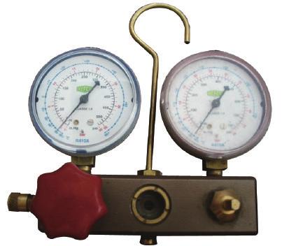
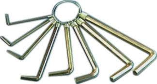
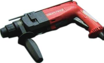

33 Service Manual Main Tools for 1. Level meter, measuring tape 2. Screw driver 3. Impact drill, drill head, electric drill Electroprobe 5. Universal meter 6. Torque wrench, open-end wrench, inner hexagon spanner 7. Electronic leakage detector 8. Vacuum pump 9. Pressure meter 10. Pipe pliers, pipe cutter 11. Pipe expander, pipe bender 12. Soldering appliance, refrigerant container
34 Space to the floor Service Manual 8. Installation 8.1 Installation Dimension Diagram Space to the ceiling At least 15cm Space to the wall At least 15cm Space to the wall At least 15cm Space to the obstruction At least 300cm At least 250cm Space to the wall At least 30cm Space to the obstruction At least 50cm Space to the obstruction At least 30cm At least 200cm Space to the obstructio Space to the obstruction At least 50cm Drainage pipe 31
35 Installation procedures Start installation Preparation before installation Read the requirements for electric connection select installation location Prepare tools Select indoor unit installation location Select outdoor unit installation location Install wall-mounting frame, drill wall holes Connect pipes of indoor unit and drainage pipe Connect wires of indoor unit Install the support of outdoor unit (select it according to the actual situation) Fix outdoor unit Install drainage joint of outdoor unit (only for cooling and heating unit) Bind up pipes and hang the indoor unit Make the bound pipes pass through the wall hole and then connect outdoor unit Connect pipes of outdoor unit Connect wires of outdoor unit Neaten the pipes Vacuum pumping and leakage detection Check after installation and test operation Finish installation te: this flow is only for reference; please find the more detailed installation steps in this section. 32
36 8.2 Installation Parts-Checking. Name. Name 1 Indoor unit 8 Sealing gum 2 Outdoor unit 9 Wrapping tape 3 Connection pipe 10 Support of outdoor unit 4 Drainage pipe 11 Fixing screw 5 Wall-mounting Drainage plug(cooling 12 frame and heating unit) 6 Connecting Owners manual, 13 cable(power cord) remote controller 7 Wall pipe te: 1.Please contact the local agent for installation. 2.Dont use unqualified power cord. 8.3 Selection of Installation Location 1. Basic Requirement: Installing the unit in the following places may cause malfunction. If it is unavoidable, please consult the local dealer: (1) The place with strong heat sources, vapors, flammable or explosive gas, or volatile objects spread in the air. (2) The place with high-frequency devices (such as welding machine, medical equipment). (3) The place near coast area. (4) The place with oil or fumes in the air. (5) The place with sulfureted gas. (6) Other places with special circumstances. (7) The appliance shall not be installed in the laundry. 2. Indoor Unit: (1) There should be no obstruction near air inlet and air outlet. (2) Select a location where the condensation water can be dispersed easily and wont affect other people. (3) Select a location which is convenient to connect the outdoor unit and near the power socket. (4) Select a location which is out of reach for children. (5) The location should be able to withstand the weight of indoor unit and wont increase noise and vibration. (6) The appliance must be installed 2.5m above floor. (7) Dont install the indoor unit right above the electric appliance. (8) Please try your best to keep way from fluorescent lamp. 3. Outdoor Unit: (1) Select a location where the noise and outflow air emitted by the outdoor unit will not affect neighborhood. (2) The location should be well ventilated and dry, in which the outdoor unit wont be exposed directly to sunlight or strong wind. (3) The location should be able to withstand the weight of outdoor unit. (4) Make sure that the installation follows the requirement of installation dimension diagram. (5) Select a location which is out of reach for children and far away from animals or plants.if it is unavoidable, please add fence for safety purpose. 8.4 Requirements for electric connection 1. Safety Precaution (1) Must follow the electric safety regulations when installing the unit. (2) According to the local safety regulations, use qualified power supply circuit and air switch. (3) Make sure the power supply matches with the requirement of air conditioner. Unstable power supply or incorrect wiring may result in electric shock,fire hazard or malfunction. Please install proper power supply cables before using the air conditioner. (4) Properly connect the live wire, neutral wire and grounding wire of power socket. (5) Be sure to cut off the power supply before proceeding any work related to electricity and safety. (6) Do not put through the power before finishing installation. (7) If the supply cord is damaged,it must be replaced by the manufacturer,its service agent or similarly qualified persons in order to avoid a hazard. (8) The temperature of refrigerant circuit will be high, please keep the interconnection cable away from the copper tube. (9) The appliance shall be installed in accordance with national wiring regulations. Please notice that the unit is filled with flammable gas R32. Inappropriate treatment of the unit involves the risk of severe damages of people and material. Details to this refrigerant are found in chapter refrigerant. 2. Grounding Requirement: (1) The air conditioner is first class electric appliance. It must be properly grounding with specialized grounding device by a professional. Please make sure it is always grounded effectively, otherwise it may cause electric shock. (2) The yellow-green wire in air conditioner is grounding wire, which cant be used for other purposes. (3) The grounding resistance should comply with national electric safety regulations. (4) The appliance must be positioned so that the plug is accessible. (5) An all-pole disconnection switch having a contact separation of at least 3mm in all poles should be connected in fixed wiring. (6) Including an air switch with suitable capacity, please note the following table. Air switch should be included magnet buckle and heating buckle function, it can protect the circuitshort and overload. (Caution: please do not use the fuse only for protect the circuit) Air-conditioner Air switch capacity 09K 10A 12K 13A 8.5 Installation of Indoor Unit 1. Choosing Installation Iocation Recommend the installation location to the client and then confirm it with the client. 2. Install Wall-mounting Frame (1) Hang the wall-mounting frame on the wall; adjust it in horizontal position with the level meter and then point out the screw fixing holes on the wall. (2) Drill the screw fixing holes on the wall with impact drill (the 33
37 specification of drill head should be the same as the plastic expansion particle) and then fill the plastic expansion particles in the holes. (3) Fix the wall-mounting frame on the wall with tapping screws (ST4.2X25TA) and then check if the frame is firmly installed by pulling the frame. If the plastic expansion particle is loose, please drill another fixing hole nearby. 3. Install Wall-mounting Frame (1) Choose the position of piping hole according to the direction of outlet pipe. The position of piping hole should be a little lower than the wall-mounted frame.(as show in Fig.1) Wall Space to the wall above 150mm Left Right Φ55mm Fig.1 Φ55mm Rear piping hole Rear piping hole (2) Open a piping hole with the diameter of Φ55mm on the selected outlet pipe position.in order to drain smoothly, slant the piping hole on the wall slightly downward to the outdoor side with the gradient of 5-10.(As show in Fig.2) Indoor Outdoor te: Mark in the middle of it 5-10 Level meter Fig.2 Φ55mm Space to the wall above 150mm Wall (1) Pay attention to dust prevention and take relevant safety measures when opening the hole. (2) The plastic expansion particles are not provided and should be bought locally. 4. Outlet Pipe (1) The pipe can be led out in the direction of right, rear right, left or rear left.(as show in Fig.3) (2) When selecting leading out the pipe from left or right, please cut off the corresponding hole on the bottom case.(as show in Fig.4) 5. Connect the Pipe of Indoor Unit (1) Aim the pipe joint at the corresponding bellmouth.(as show in Fig.5) (2) Pretightening the union nut with hand. (3) Adjust the torque force by referring to the following sheet. Place the open-end wrench on the pipe joint and place the torque wrench on the union nut. Tighten the union nut with torque wrench.(as show in Fig.6) (4) Wrap the indoor pipe and joint of connection pipe with insulating pipe, and then wrap it with tape.(as show in Fig.7) Pipe joint Union nut Outlet pipe Pipe Fig.5 Drain hose Torque wrench Indoor pipe Insulating pipe Refer to the following table for wrench moment of force: Fig.8 Drain hose Outlet pipe Tape Fig.7 Open-end wrench Union nut Fig.6 Hex nut diameter(mm) Tightening torque(n.m) Φ6 15~20 Φ ~40 Φ12 45~55 Φ16 60~65 Φ19 70~75 Fig.9 Pipe 6. Install Drain Hose (1) Connect the drain hose to the outlet pipe of indoor unit.(as show in Fig.8) (2) Bind the joint with tape.(as show in Fig.9) te: Fig.3 Right Rear right Left Rear left (1) Add insulating pipe in the indoor drain hose in order to prevent condensation. (2) The plastic expansion particles are not provided. (As show in Fig.10) Left Right Drain hose Cut off the hole Fig.4 Insulating pipe Fig.10 34
38 7. Connect Wire of Indoor Unit (1) Open the panel, remove the screw on the wiring cover and then take down the cover.(as show in Fig.11) Fig.11 Panel Screw Wiring cover 8. Bind up Pipe (1) Bind up the connection pipe, power cord and drain hose with the band.(as show in Fig.14) (2) Reserve a certain length of drain hose and power cord for installation when binding them. When binding to a certain degree, separate the indoor power and then separate the drain hose.(as show in Fig.15) (3) Bind them evenly. (4) The liquid pipe and gas pipe should be bound separately at the end. (2) Make the power connection wire go through the cable-cross hole at the back of indoor unit and then pull it out from the front side.(as show in Fig.12) Indoor unit Indoor and outdoor power cord Gas pipe Cable-cross hole Fig.14 Band Liquid pipe Drain hose Power connection wire Fig.12 (3) Remove the wire clip; connect the power connection wiresignal control wire (only for cooling and heating unit) to the wiring terminal according to the color; tighten the screw and then fix the power connection wire with wire clip.(as show in Fig.13) Connection pipe Indoor power cord Drain hose Band Fig.15 Fig.13 N(1) 2 3 blue black brown yellowgreen te: (1) The power cord and control wire cant be crossed or winding. (2) The drain hose should be bound at the bottom. Outdoor unit connection te: The wiring connect is for reference only, please refer to the actual one. (4) Put wiring cover back and then tighten the screw. (5) Close the panel. te: (1) All wires of indoor unit and outdoor unit should be connected by a professional. (2) If the length of power connection wire is insufficient, please contact the supplier for a new one. Avoid extending the wire by yourself. (3) For the air conditioner with plug, the plug should be reachable after finishing installation. (4) For the air conditioner without plug, an air switch must be installed in the line. The air switch should be all-pole parting and the contact parting distance should be more than 3mm. 9. Hang the Indoor Unit (1) Put the bound pipes in the wall pipe and then make them pass through the wall hole. (2) Hang the indoor unit on the wall-mounting frame. (3) Stuff the gap between pipes and wall hole with sealing gum. (4) Fix the wall pipe.(as show in Fig.16) (5) Check if the indoor unit is installed firmly and closed to the wall.(as show in Fig.17) Indoor Wall pipe Fig.16 Outdoor Sealing gum Fig.17 Upper hook Lower hook of wall-mounting frame te: Do not bend the drain hose too excessively in order to prevent blocking. 35
39 8.6 Installation of Outdoor unit 1. Fix the Support of Outdoor Unit(Select it according to the actual installation situation) (1) Select installation location according to the house structure. (2) Fix the support of outdoor unit on the selected location with expansion screws. te: (1) Take sufficient protective measures when installing the outdoor unit. (2) Make sure the support can withstand at least four times the unit weight. (3) The outdoor unit should be installed at least 3cm above the floor in order to install drain joint.(as show in Fig.18) (4) For the unit with cooling capacity of 2300W~5000W, 6 expansion screws are needed; for the unit with cooling capacity of 6000W~8000W, 8 expansion screws are needed; for the unit with cooling capacity of 10000W~16000W, 10 expansion screws are needed. Refer to the following table for wrench moment of force: 5. Connect Outdoor Electric Wire (1) Remove the wire clip; connect the power connection wire and signal control wire (only for cooling and heating unit) to the wiring terminal according to the color; fix them with screws.(as show in Fig.23) Fig.23 Hex nut diameter(mm) Tightening torque(n.m) Φ6 15~20 Φ ~40 Φ12 45~55 Φ16 60~65 Φ19 70~75 N(1) 2 3 N L blue black brown blue brown (black) yellowgreen yellowgreen Indoor unit connection N L POWER handle Outdoor drain joint Drain hose At least 3cm above the floor Fig.18 Fig Install Drain Joint(Only for cooling and heating unit) (1) Connect the outdoor drain joint into the hole on the chassis. (2) Connect the drain hose into the drain vent. (As show in Fig.19) 3. Fix Outdoor Unit (1) Place the outdoor unit on the support. (2) Fix the foot holes of outdoor unit with bolts. (As show in Fig.20) Foot holes Handle Foot holes Fig.21 Fig Connect Indoor and Outdoor Pipes (1) Remove the screw on the right handle of outdoor unit and then remove the handle.(as show in Fig.21) (2) Remove the screw cap of valve and aim the pipe joint at the bellmouth of pipe.(as show in Fig.22) Liquid valve Liquid pipe gas pipe gas valve Fig.22 Drain vent Pipe joint (3) Pretightening the union nut with hand. (4) Tighten the union nut with torque wrench. Chassis Union nut Screw te: the wiring connect is for reference only,please refer to the actual one. (2) Fix the power connection wire and signal control wire with wire clip (only for cooling and heating unit). te: (1) After tightening the screw, pull the power cord slightly to check if it is firm. (2) Never cut the power connection wire to prolong or shorten the distance. 6. Neaten the Pipes (1) The pipes should be placed along the wall, bent reasonably and hidden possibly. Min. semidiameter of bending the pipe is 10cm. (2) If the outdoor unit is higher than the wall hole, you must set a U-shaped curve in the pipe before pipe goes into the room, in order to prevent rain from getting into the room.(as show in Fig.24) Fig.24 te: U-shaped curve Drain hose Wall Fig.25 The drain hos can't raise upwards (1) The through-wall height of drain hose shouldnt be higher than the outlet pipe hole of indoor unit.(as show in Fig.25) (2) Slant the drain hose slightly downwards. The drain hose cant be curved, raised and fluctuant, etc.(as show in Fig.26) 36
40 (3) The water outlet cant be placed in water in order to drain smoothly.(as show in Fig.27) The drain hose can't be fluctuant The drain hose can't be fluctuant Fig.26 Liquid valve Gas valve Refrigerant charging vent Nut of refrigerant Charging vent The water outlet can't be fluctuant Piezometer Valve cap Inner hexagon spanner Lo Vacuum pump Close Open The water outlet can't be placed in water 8.7 Vacuum Pumping and Leak Detection 1. Use Vacuum Pump (1) Remove the valve caps on the liquid valve and gas valve and the nut of refrigerant charging vent. (2) Connect the charging hose of piezometer to the refrigerant charging vent of gas valve and then connect the other charging hose to the vacuum pump. (3) Open the piezometer completely and operate for 10-15min to check if the pressure of piezometer remains in -0.1MPa. (4) Close the vacuum pump and maintain this status for 1-2min to check if the pressure of piezometer remains in -0.1MPa. If the pressure decreases, there may be leakage. (5) Remove the piezometer, open the valve core of liquid valve and gas valve completely with inner hexagon spanner. (6) Tighten the screw caps of valves and refrigerant charging vent.(as show in Fig.28) Fig.28 Hi Fig Check after Installation and Test operation 1. Check after Installation Check according to the following requirement after finishing installation. NO. Items to be checked Possible malfunction 1 Has the unit been The unit may drop, shake or installed firmly? emit noise. 2 Have you done the It may cause insufficient cooling refrigerant leakage test? (heating) capacity. 3 Is heat insulation of It may cause condensation and pipeline sufficient? water dripping. 4 Is water drained well? It may cause condensation and water dripping. Is the voltage of power 5 supply according to the It may cause malfunction or voltage marked on the damage the parts. nameplate? Is electric wiring and pipeline installed correctly? Is the unit grounded securely? Does the power cord follow the specification? Is there any obstruction It may cause malfunction or damage the parts. It may cause electric leakage. It may cause malfunction or damage the parts. It may cause insufficient cooling in air inlet and air outlet? (heating) capacity. The dust and sundries caused It may cause malfunction or during installation are damaging the parts. removed? The gas valve and liquid It may cause insufficient cooling valve of connection pipe (heating) capacity. are open completely? Is the inlet and outlet of piping hole been covered? It may cause insufficient cooling (heating) capacity or waster eletricity. 2. Test Operation (1) Preparation of test operation The client approves the air conditioner installation. Specify the important notes for air conditioner to the client. (2) Method of test operation Put through the power, press ON/OFF button on the remote controller to start operation. Press MODE button to select AUTO, COOL, DRY, FAN and HEAT to check whether the operation is normal or not. If the ambient temperature is lower than 16, the air conditioner cant start cooling. 2. Leakage Detection (1) With leakage detector: Check if there is leakage with leakage detector. (2) With soap water: If leakage detector is not available, please use soap water for leakage detection. Apply soap water at the suspected position and keep the soap water for more than 3min. If there are air bubbles coming out of this position, theres a leakage. 37
41 9. Maintenance 9.1 Error Code List NO. Malfunction Name Display Method of Indoor Unit Indicator Display (during blinking, ON 0.5s Dual-8 and OFF 0.5s) Code Operation Cool Heating Display Indicator Indicator Indicator A/C status Possible Causes 1 High pressure protection of system E1 During cooling and drying operation, except indoor fan operates, all loads stop operation. During heating operation, the complete unit stops. Possible reasons: 1. Refrigerant was superabundant; 2. Poor heat exchange (including filth blockage of heat exchanger and bad radiating environment ); Ambient temperature is too high. 2 Antifreezing protection E2 During cooling and drying operation, compressor and outdoor fan stop while indoor fan operates. 1. Poor air-return in indoor unit; 2. Fan speed is abnormal; 3. Evaporator is dirty. 3 System block or refrigerant leakage E3 The Dual-8 Code Display will show E3 until the low pressure switch stop operation. 1.Low-pressure protection 2.Low-pressure protection of system 3.Low-pressure protection of compressor 4 High discharge temperature protection of compressor E4 During cooling and drying operation, compressor and outdoor fan stop while indoor fan operates. During heating operation, all loads stop. Please refer to the malfunction analysis (discharge protection, overload). 5 Overcurrent protection E5 During cooling and drying operation, compressor and outdoor fan stop while indoor fan operates. During heating operation, all loads stop. 1. Supply voltage is unstable; 2. Supply voltage is too low and load is too high; 3. Evaporator is dirty. 6 Communication Malfunction E6 During cooling operation, compressor stops while indoor fan motor operates. During heating operation, the complete unit stops. Refer to the corresponding malfunction analysis. 7 High temperature resistant protection E8 During cooling operation: compressor will stop while indoor fan will operate. During heating operation, the complete unit stops. Refer to the malfunction analysis (overload, high temperature resistant). 8 EEPROM malfunction EE During cooling and drying operation, compressor will stop while indoor fan will operate; During heating operation, the complete unit will stop Replace outdoor control panel AP1 9 Limit/ decrease frequency due to high temperature of module EU All loads operate normally, while operation frequency for compressor is decreased Discharging after the complete unit is de-energized for 20mins, check whether the thermal grease on IPM Module of outdoor control panel AP1 is sufficient and whether the radiator is inserted tightly. If its no use, please replace control panel AP1. 10 Malfunction protection of jumper cap C5 Wireless remote receiver and button are effective, but can not dispose the related command 1. jumper cap insert on mainboard. 2. Incorrect insert of jumper cap. 3. Jumper cap damaged. 4. Abnormal detecting circuit of mainboard. 38
42 NO. Malfunction Name Display Method of Indoor Unit Indicator Display (during Dual-8 blinking, ON 0.5s and OFF Code 0.5s) Display Operation Cool Heating Indicator Indicator Indicator A/C status Possible Causes 11 Gathering refrigerant F0 When the outdoor unit receive signal of Gathering refrigerant,the system will be forced to run under cooling mode for gathering refrigerant minal cooling mode 12 Indoor ambient temperature sensor is open/short circuited F1 During cooling and drying operation, indoor unit operates while other loads will stop; during heating operation, the complete unit will stop operation. 1. Loosening or bad contact of indoor ambient temp. sensor and mainboard terminal. 2. Components in mainboard fell down leads short circuit. 3. Indoor ambient temp. sensor damaged.(check with sensor resistance value chart) 4. Mainboard damaged. 13 Indoor evaporator temperature sensor is open/short circuited F2 AC stops operation once reaches the setting temperature. Cooling, drying: internal fan motor stops operation while other loads stop operation; heating: AC stop operation 1. Loosening or bad contact of Indoor evaporator temp. sensor and mainboard terminal. 2. Components on the mainboard fall down leads short circuit. 3. Indoor evaporator temp. sensor damaged.(check temp. sensor value chart for testing) 4. Mainboard damaged Outdoor ambient temperature sensor is open/short circuited Outdoor condenser temperature sensor is open/short circuited F3 F4 During cooling and drying operating, compressor stops while indoor fan operates; During heating operation, the complete unit will stop operation During cooling and drying operation, compressor stops while indoor fan will operate; During heating operation, the complete unit will stop operation. Outdoor temperature sensor hasnt been connected well or is damaged. Please check it by referring to the resistance table for temperature sensor) Outdoor temperature sensor hasnt been connected well or is damaged. Please check it by referring to the resistance table for temperature sensor) 16 Outdoor discharge temperature sensor is open/short circuited F5 During cooling and drying operation, compressor will sop after operating for about 3 mins, while indoor fan will operate; During heating operation, the complete unit will stop after operating for about 3 mins. 1.Outdoor temperature sensor hasnt been connected well or is damaged. Please check it by referring to the resistance table for temperature sensor) 2.The head of temperature sensor hasnt been inserted into the copper tube 17 Limit/ decrease frequency due to overload F6 All loads operate normally, while operation frequency for compressor is decreased Refer to the malfunction analysis (overload, high temperature resistant) 18 Decrease frequency due to overcurrent F8 All loads operate normally, while operation frequency for compressor is decreased The input supply voltage is too low; System pressure is too high and overload 39
43 NO Malfunction Name Decrease frequency due to high air discharge Limit/ decrease frequency due to antifreezing Display Method of Indoor Unit Indicator Display (during Dual-8 blinking, ON 0.5s and OFF Code 0.5s) A/C status Possible Causes Display Operation Cool Heating Indicator Indicator Indicator All loads operate normally, while Overload or temperature is too high; F9 operation frequency for Refrigerant is insufficient; compressor is decreased Malfunction of electric expansion valve (EKV) FH All loads operate normally, while operation Poor air-return in indoor unit or fan speed is too low frequency for compressor is decreased 21 Voltage for DC bus-bar is too high PH During cooling and drying operation, compressor will stop while indoor fan will operate; During heating operation, the complete unit will stop operation. 1. Measure the voltage of position L and N on wiring board (XT), if the voltage is higher than 265VAC, turn on the unit after the supply voltage is increased to the normal range. 2.If the AC input is normal, measure the voltage of electrolytic capacitor C on control panel (AP1), if its normal, theres malfunction for the circuit, please replace the control panel (AP1) 22 Voltage of DC bus-bar is too low PL During cooling and drying operation, compressor will stop while indoor fan will operate; During heating operation, the complete unit will stop 1. Measure the voltage of position L and N on wiring board (XT), if the voltage is higher than 150VAC, turn on the unit after the supply voltage is increased to the normal range. 2.If the AC input is normal, measure the voltage of electrolytic capacitor C on control panel (AP1), if its normal, theres malfunction for the circuit, please replace the control panel (AP1) 23 Compressor Min frequence in test state P0 Showing during min. cooling or min. heating test 24 Compressor rated frequence in test state P1 Showing during nominal cooling or nominal heating test 25 Compressor maximum frequence in test state P2 Showing during max. cooling or max. heating test 40
44 NO. Malfunction Name Display Method of Indoor Unit Indicator Display (during Dual-8 blinking, ON 0.5s and OFF Code 0.5s) Display Operation Cool Heating Indicator Indicator Indicator A/C status Possible Causes 26 Compressor intermediate frequence in test state P3 Showing during middle cooling or middle heating test 27 Overcurrent protection of phase current for compressor P5 During cooling and drying operation, compressor will stop while indoor fan will operate; During heating operation, the complete unit will stop operation. Refer to the malfunction analysis (IPM protection, loss of synchronism protection and overcurrent protection of phase current for compressor. 28 Charging malfunction of capacitor PU During cooling and drying operation, compressor will stop while indoor fan will operate; During heating operation, the complete unit will stop Refer to the part three charging malfunction analysis of capacitor 29 Malfunction of module temperature sensor circuit P7 During cooling and drying operation, compressor will stop while indoor fan will operate; During heating operation, the complete unit will stop Replace outdoor control panel AP1 30 Module high temperature protection P8 During cooling operation, compressor will stop while indoor fan will operate; During heating operation, the complete unit will stop After the complete unit is de-energized for 20mins, check whether the thermal grease on IPM Module of outdoor control panel AP1 is sufficient and whether the radiator is inserted tightly. If its no use, please replace control panel AP1. 31 Overload protection for compressor H3 During cooling and drying operation, compressor will stop while indoor fan will operate; During heating operation, the complete unit will stop operation. 1. Wiring terminal OVC-COMP is loosened. In normal state, the resistance for this terminal should be less than 1ohm. 2.Refer to the malfunction analysis ( discharge protection, overload) 32 IPM protection H5 During cooling and drying operation, compressor will stop while indoor fan will operate; During heating operation, the complete unit will stop operation. Refer to the malfunction analysis (IPM protection, loss of synchronism protection and overcurrent protection of phase current for compressor. 33 Malfunction of zero-cross detection circuit U8 The complete unit stops 1.Power supply is abnormal; 2.Detection circuit of indoor control mainboard is abnormal. 41
45 NO Malfunction Name Internal motor (fan motor) do not operate Desynchronizing of compressor Display Method of Indoor Unit Indicator Display (during Dual-8 Code blinking, ON 0.5s and OFF 0.5s) Display Operation Cool Heating Indicator Indicator Indicator H6 H7 A/C status Internal fan motor, external fan motor, compressor and electric heater stop operation,guide louver stops at present location. During cooling and drying operation, compressor will stop while indoor fan will operate; During heating operation, the complete unit will stop operation. Possible Causes 1. Bad contact of DC motor feedback terminal. 2. Bad contact of DC motor control end. 3. Fan motor is stalling. 4. Motor malfunction. 5. Malfunction of mainboard rev detecting circuit. Refer to the malfunction analysis (IPM protection, loss of synchronism protection and overcurrent protection of phase current for compressor. 36 Outdoor DC fan motor malfunction L3 Outdoor DC fan motor malfunction lead to compressor stop operation, DC fan motor malfunction or system blocked or the connector loosed 37 power protection L9 compressor stop operation and Outdoor fan motor will stop 30s latter, 3 minutes latter fan motor and compressor will restart To protect the electronical components when detect high power Indoor unit and outdoor unit doesnt match Failure startup LP LC compressor and Outdoor fan motor cant work During cooling and drying operation, compressor will stop while indoor fan will operate; During heating operation, the complete unit will stop operation. Indoor unit and outdoor unit doesnt match Refer to the malfunction analysis 40 rmal communication 41 Defrosting 42 PFC protection HC OFF 3S and blink once Defrosting will occur in heating (during mode. Compressor will operate blinking, while indoor fan will stop ON 10s operation. and OFF 0.5s) During cooling and drying operation, compressor will stop while indoor fan will operate; During heating operation, the complete unit will stop operation. Its the normal state Replace outdoor control panel AP1 or Reactor 42
46 NO. Malfunction Name Display Method of Indoor Unit Indicator Display (during Dual-8 blinking, ON 0.5s and OFF Code 0.5s) Display Operation Cool Heating Indicator Indicator Indicator A/C status Possible Causes 43 Malfunction of phase current detection circuit for compressor U1 During cooling and drying operation, compressor will stop while indoor fan will operate; During heating operation, the complete unit will stop Replace outdoor control panel AP1 44 Malfunction of voltage dropping for DC bus-bar U3 During cooling and drying operation, compressor will stop while indoor fan will operate; During heating operation, the complete unit will stop Supply voltage is unstable 45 Malfunction of complete units current detection U5 During cooling and drying operation, the compressor will stop while indoor fan will operate; During heating operating, the complete unit will stop operation. Theres circuit malfunction on outdoor units control panel AP1, please replace the outdoor units control panel AP1. 46 The four-way valve is abnormal U7 If this malfunction occurs during heating operation, the complete unit will stop operation. 1.Supply voltage is lower than AC175V; 2.Wiring terminal 4V is loosened or broken; 3.4V is damaged, please replace 4V. 47 Frequency limiting (power) 48 Compressor is opencircuited 49 The temperature for turning on the unit is reached 50 Frequency limiting (module temperature) 51 Malfunction of detecting plate(wifi) JF 43
47 If malfunction occurs,corresponding code will display and the unit will resume normal until protection or malfunction disappears. 44
48 Analysis or processing of some of the malfunction display: 1. Compressor discharge protection Possible causes: shortage of refrigerant; blockage of air filter; poor ventilation or air flow short pass for condenser; the system has noncondensing gas (such as air, water etc.); blockage of capillary assy (including filter); leakage inside four-way valve causes incorrect operation; malfunction of compressor; malfunction of protection relay; malfunction of discharge sensor; outdoor temperature too high. Processing method: refer to the malfunction analysis in the above section. 2. Low voltage overcurrent protection Possible cause: Sudden drop of supply voltage. 3. Processing method: Check if communication signal cable is connected reliably. 4. Sensor open or short circuit Processing method: Check whether sensor is normal, connected with the corre sponding position on the controller and if damage of lead wire is found. 5. Compressor over load protection Possible causes: insufficient or too much refrigrant; blockage of capillary and increase of suction temp.; improper running of compressor, burning in or stuck of bearing, damage of discharge valve; malfunction of protector. Processing method: adjust refrigerant amount; replace the capillary; replace the compressor; use universal meter to check if the contactor of compress or is fine when it is not overheated, if not replace the protector. 6. System malfunction i.e.overload protection.when tube temperature(check the temperature of outdoor heat exchanger when cooling and check the temperatur e of indoor heat exchanger when heating) is too high, protection will be activated. Possible causes: Outdoor temperature is too high when cooling; insufficient outdoor air circulation; refrigerant flow malfunction. please refer to the malfunction analysis in the previous section for handling method. 7. IPM module protection Processing method:once the module malfunction happens,if it persists for a long time and can not be selfcanceled, cut off the power and turn off the unit,and then re-energize the unit again after about 10 min.after repeating the procedure for sever times, if the malfunction still exists,replace the module. 45
49 9.2 Procedure of Troubleshooting 1. Malfunction of Temperature Sensor F1, F2 Main detection points: Is the wiring terminal between the temperature sensor and the controller loosened or poorly contacted? Is there short circuit due to trip-over of the parts? Is the temperature sensor broken? Is mainboard broken? Malfunction diagnosis process: Start Is the wiring terminal between the temperature sensor and the controller loosened or poorly contacted? Insert the temperature sensor tightly Is malfunction eliminated Is there short circuit due to tripover of the parts Make the parts upright Is malfunction eliminated Is the temperature sensor normal according to the resistance table? Replace it with a temperature sensor with the same model Is malfunction eliminated Replace the mainboard with the same model. End 46
50 2. Malfunction of Blocked Protection of IDU Fan Motor H6 Main detection points: SmoothlyIs the control terminal of PG motor connected tightly? SmoothlyIs the feedback interface of PG motor connected tightly? The fan motor can't operate? The motor is broken? Detectioncircuit of the mainboard is defined abnormal? Malfunction diagnosis process: Start While power is off stir the blade with a tool to see whether the blade rotates smoothly Tighten the screw; reassemble the blade, motor and shaft bearing rubber base sub-assy to make sure there is no foreign object between them Is malfunction eliminated Check if the connection of PG motor feedback terminal is firm Insert the control terminal of PG motor tightly Is malfunction eliminated Check if the connection of PG motor control terminal is firm Reinstall the blade and motor correctly Is malfunction eliminated Turn on the unit again; measure whether the output voltage on control terminal for PG motor is more than 50V within 1 min after the louvers are opened Is the motor started up Measure the voltage of this foot to neutral wire on the mainboard Replace PG motor Replace the mainboard with the same model Is malfunction eliminated End 47
51 3. Malfunction of Protection of Jumper Cap C5 Main detection points: Is there jumper cap on the mainboard? Is the jumper cap inserted correctly and tightly? The jumper is broken? The motor is broken? Detection circuit of the mainboard is defined abnormal? Malfunction diagnosis process: Start Is there jumper cap on the mainboard? Appearance of the jumper cap Assemble the jumper cap with the same model Is malfunction eliminated Is the jumper cap inserted correctly and tightly? Insert the jumper cap tightly Is malfunction eliminated Replace the jumper cap with the same model Is malfunction eliminated Replace the mainboard with the same model End 48
52 4. Malfunction of Zero-crossing Inspection Circuit Malfunction of the IDU Fan Motor U8 Main detection points: Instant energization afte de-energization while the capacitordischarges slowly? The zero-cross detectioncircuit of the mainboard is defined abnormal? Malfunction diagnosis process: Start Turn power off for 1minute,the turn back on U8 is still displayed The unit returns to normal. Conclusion:U8 is displayed due to power off/on while the capacitor discharges slowly. The zero-cross detection circuit of the mainboard is defined abnormal.replace the mainboard with the same model End 49
53 5. High Temperature and Overload Protection (AP1 below means control board of outdoor unit) E8 Start If the outdoor ambient temperature is higher than 53 C? rmal protection, please use it after improving the outdoor ambient temperature Unit restarts normally is good? Improve the radiating environment of unit (clean the heat exchanger and remove surrounding obstacles) Unit restarts normally If the indoor and outdoor fan are running normally? Connect normally? Adjust the connection Replace outdoor mainboard Fan capacitor is broken? Replace fan capacitor Motor is broken? Replace motor Replace mainboard End 50
54 6. Malfunction of detecting plate(wifi) JF Start check if the connection wire are correctly connected Replace the detecting plate with the same model Is malfunction eliminated Replace the mainboard with the same model The end 51
55 Outdoor unit: (1) Capacitor charge fault (Fault with outdoor unit) (AP1 below refers to the outdoor control panel) Main Check Points: Use AC voltmeter to check if the voltage between terminal L and N on the wiring board is within 210VAC~240VAC. Is the reactor (L) correctly connected? Is the connection loose or fallen? Is the reactor (L) damaged? Fault diagnosis process: Turn on the unit and wait 1 minute Use DC voltmeter to measure the voltage on the two ends of electrolytic capacitor Voltage higher than 200V? Fault with the voltage testing circuit on control panel AP1 Replace the control panel AP1 Measure the AC voltage between terminal L and N on wiring board XT(power supply) Voltage within 210VAC~250VAC? Shut down the power and repair the power supply to restore the range 210VAC~250VAC power on and restart the unit If the fault is eliminated? Shut down the power and wait 20 minutes; or use DC voltmeter to measure the voltage on the two ends of capacitor, until the voltage is lower than 20V Check the connection of reactor (L in the Electrical Wiring Diagram) If the wiring of reactor Lis normal? Connect the reactor Laccording to Electrical Wiring Diagram correctly Re-energize and turn on the unit If the fault is eliminated? Replace the control panel AP1 End 52
56 (2). IPM protection, phase current overcurrent (the control board as below indicates the control board of outdoor unit) H5/P5 Mainly detect: (1) Compressor COMP terminal (2) voltage of power supply (3) compressor (4) Refrigerant-charging volume (5) air outlet and air inlet of outdoor/indoor unit Troubleshooting: Turn on the unit after energization Whether IPM protection occurs after the unit has operated for a while? Check the connection between the control board and the compressor by referring to the electric wiring diagram Measure the voltage between terminal L and terminal N with AC volmeter Whether the voltage between terminal L and terminal N of XT is within 210AVC~ 250VAC? Correctly connect the wires of compressor according to the electric wiring diagram, and then turn on the unit Check the power supply voltage and make the power voltage resume to the range of 210VAC~250VAC Check whether wires of compressor (UVW) are connected correctly Measure the resistance value among three terminals (UVW) of compressor with a resistance measuring meter. Whether the resistance value of three terminals are almost the same. 1. Whether the heat exchangers of indoor unit and outdoor unit are dirty? Whether the radiation is affected because the unit is covered by the objects? 2. When indoor fan and outdoor unit are operate normally? 3. Whether the system pressure is too high? 4. Whether the pressure is because there's too much refrigerant? Whether there's abnormal phenomenons described as above? Correct it one by one according to the Service Manual, and then turn on the unit. Measure the resistance between three terminals (UVW) of compressor and the copper pipe with resistance measuring meter Whether the resistance value is more than 500ohm? Replace the compressor Whether the unit can operate normally? Replace control board End 53
57 (3) High temperature and overload protection diagnosis (AP1 hereinafter refers to the control board of the outdoor unit) Mainly detect: Is outdoor ambient temperature in normal range? Are the outdoor and indoor fans operating normally? Is the heat dissipation environment inside and outside the unit good? Fault diagnosis process: Overheat and high temperature protection Is outdoor ambient temperature higher than 53? rmal protection, please operate it after the outdoor ambient temperature is normalized. 20 minutes after the complete unit is powered off. Is heat dissipation of the indoor unit and outdoor unit abnormal? Improve the heat dissipation environment of the unit Does the outdoor fan work normally? 1. Check if the fan terminal OFAN is connected correctly 2. Resistance between any two terminals is measure by an ohm gauge and should be less than 1K Ohm. Replace the control panel AP1 Replace the fan capacitor C1 Replace the outdoor fan End 54
58 (4) Start-up failure (following AP1 for outdoor unit control board) Mainly detect: Whether the compressor wiring is connected correct? Is compressor broken? Is time for compressor stopping enough? Fault diagnosis process: Power on the unit Is stop time of the compressor longer than 3 minutes? Restart it up after 3 minutes Does startup fail? Are the wires for the compressor connected correctly? Is connection sequence right? Connect the wires as per the connection diagram Replace the control panel AP1 If the fault is eliminated? Replace the compressor End 55
59 (5) Out of step diagnosis for the compressor (AP1 hereinafter refers to the control board of the outdoor unit) Mainly detect: Is the system pressure too high? Is the input voltage too low? Fault diagnosis process: Out of step occurs once the unit is powered on. Out of step occurs in operation Is stop time of the compressor longer than 3 minutes? Is the outdoor fan working normally? Check if the fan terminal OFAN is connected correctly Replace the fan capacitor C1 Is the outdoor unit blocked by foreign objects? Remove foreign objects Replace the outdoor fan Are the wires for the compressor connected correctly? Is connection sequence right? Is the connection made in clockwise direction? Replace the control panel AP1 Connect the wires correctly Replace the control panel AP1 If the fault is eliminated? If the fault is eliminated? Replace the compressor Replace the compressor End End 56
60 (6) Overload and air exhaust malfunction diagnosis (following AP1 for outdoor unit control board) Mainly detect: Is the PMV connected well or not? Is PMV damaged? Is refrigerant leaked? Fault diagnosis process: 20 minutes after the complete unit is powered off Is the terminal FA for the electronic expansion valve connected correctly? Connect the wires correctly Resistances between the first four pins close to the terminal hole and the fifth pin are almost the same, less than 100 ohm. Replace the electronic expansion valve If the fault is eliminated? Replace the control panel AP1 If the fault is eliminated? Coolant leakage, refilling the coolant End 57
61 (7) Communication malfunction: (following AP1 for outdoor unit control board) Mainly detect: Is there any damage for the indoor unit mainboard communication circuit? Is communication circuit damaged? Detect the indoor and outdoor units connection wire and indoor and outdoor units inside wiring is connect well or not, if is there any damage? Fault diagnosis process: Start Did the equipment operate normally before the failure occurs? Check the wiring of the indoor and outdoor units with reference to the wiring diagram Check wiring inside of the indoor and outdoor units Is the connection right? The AP1 voltage detection circuit is at fault Are wires broken? Correctly connect the corresponding wires for the indoor and outdoor units with reference to the wiring diagram If the fault is eliminated? Check the communication circuit of the outdoor unit If the fault is eliminated? The communication circuit is abnormal Replace the main board AP1 of the outdoor unit If the fault is eliminated? Replace the main board of the indoor unit End 58
62 (8) Malfunction of Overcurrent Protection Main detection points: Is the supply voltage unstable with big fluctuation? Is the supply voltage too low with overload? Hardware trouble? Malfunction diagnosis process: Start Is the supply voltage unstable with big fluctuation? rmal fluctuation should be within 10 % of the rated voltage on the nameplate Is malfunction eliminated Is the supply voltage too low with overload? Adjust the supply voltage to maintain it within normal range Is malfunction eliminated Is the indoor / outdoor heat exchanger dirty,or are the air inlet and outlet blocked? Clean the indoor and outdoor heat exchangers and remove the blockage of air inlet and outlet Is malfunction eliminated The fan is abnormal? Fan speed is too low or fan doesnt rotate Check the motor and reinstall the motor to have the fan run normally Is malfunction eliminated Measure the current of live wire on the main board with a clamp ampere meter. Is the current higher than the value of the overcurrent protection? Replace the mainboard with the same model Is malfunction eliminated Is there blockage inside the system? (Filth blockage, ice plug, greasy blockage, the cut off valve hasnt been opened completely) Flush the heat exchangers with high pressure nitrogen Is malfunction eliminated Is the compressor running abnormally? Is there abnormal sound or oil leakage; Is the temperature of the shell too high, etc.? Replace the compressor Is malfunction eliminated Replace the mainboard with the same model End 59
63 9.3 Maintenance method for normal malfunction 1. Air Conditioner Cant be Started Up Possible Causes Discriminating Method (Air conditioner Status) Troubleshooting power supply, or poor connection for power plug Wrong wire connection between indoor unit and outdoor unit, or poor connection for wiring terminals 2. Poor Cooling (Heating) for Air Conditioner Possible Causes Discriminating Method (Air conditioner Status) Troubleshooting Set temperature is improper Observe the set temperature on remote controller Adjust the set temperature Rotation speed of the IDU fan motor is set too low Small wind blow Set the fan speed at high or medium Filter of indoor unit is blocked Check the filter to see its blocked Clean the filter Check whether the installation postion is proper Installation position for indoor unit Adjust the installation position, and install the according to installation requirement for air and outdoor unit is improper rainproof and sunproof for outdoor unit conditioner Discharged air temperature during cooling is higher than normal discharged wind temperature; Refrigerant is leaking Discharged air temperature during heating is Find out the leakage causes and deal with it. lower than normal discharged wind temperature; Add refrigerant. Units pressure is much lower than regulated range Malfunction of 4-way valve Blow cold wind during heating Replace the 4-way valve Discharged air temperature during cooling is higher than normal discharged wind temperature; Discharged air temperature during heating is Malfunction of capillary lower than normal discharged wind temperature; Replace the capillary Unitt pressure is much lower than regulated range. If refrigerant isnt leaking, part of capillary is blocked Flow volume of valve is insufficient Malfunction of horizontal louver The pressure of valves is much lower than that stated in the specification Horizontal louver cant swing Malfunction of the IDU fan motor The IDU fan motor cant operate Malfunction of the ODU fan motor The ODU fan motor cant operate Malfunction of compressor 3. Horizontal Louver Cant Swing After energization, operation indicator isnt bright and the buzzer cant give out sound Under normal power supply circumstances, operation indicator isnt bright after energization Compressor cant operate Open the valve completely Service Manual Confirm whether its due to power failure. If yes, wait for power recovery. If not, check power supply circuit and make sure the power plug is connected well. Check the circuit according to circuit diagram and connect wires correctly. Make sure all wiring terminals are connected firmly Make sure the air conditioner is grounded reliably Make sure wires of air conditioner is connected After energization, room circuit breaker trips off at Electric leakage for air conditioner correctly once Check the wiring inside air conditioner. Check whether the insulation layer of power cord is damaged; if yes, place the power cord. Model selection for air switch is After energization, air switch trips off Select proper air switch improper Malfunction of remote controller After energization, operation indicator is bright, while no display on remote controller or buttons have no action. Replace batteries for remote controller Repair or replace remote controller Refer to point 3 of maintenance method for details Refer to troubleshooting for H6 for maintenance method in details Refer to point 4 of maintenance method for details Refer to point 5 of maintenance method for details Possible Causes Discriminating Method (Air conditioner Status) Troubleshooting Wrong wire connection, or poor connection Check the wiring status according to circuit diagram Connect wires according to wiring diagram to make sure all wiring terminals are connected firmly Stepping motor is damaged Stepping motor cant operate Repair or replace stepping motor Others are all normal, while horizontal louver cant Main board is damaged Replace the main board with the same model operate 60
64 4. ODU Fan Motor Cant Operate Possible causes Discriminating method (air conditioner status) Troubleshooting Wrong wire connection, or poor connection Capacity of the ODU fan motor is damaged Power voltage is a little low or high Motor of outdoor unit is damaged 5. Compressor Cant Operate Possible causes Discriminating method (air conditioner status) Troubleshooting Wrong wire connection, or poor connection 6. Air Conditioner is Leaking Check the wiring status according to circuit diagram Check the wiring status according to circuit diagram Connect wires according to wiring diagram to make sure all wiring terminals are connected firmly Measure the capacity of fan capacitor with an universal meter and find that the capacity is out of Replace the capacity of fan the deviation range indicated on the nameplate of fan capacitor. Use universal meter to measure the power supply Suggest to equip with voltage regulator voltage. The voltage is a little high or low When unit is on, cooling/heating performance Change compressor oil and refrigerant. If no is bad and ODU compressor generates a lot of better, replace the compressor with a new one noise and heat. Connect wires according to wiring diagram to make sure all wiring terminals are connected firmly Measure the capacity of fan capacitor with an Capacity of compressor is universal meter and find that the capacity is out of Replace the compressor capacitor damaged the deviation range indicated on the nameplate of fan capacitor. Power voltage is a little low or Use universal meter to measure the power supply Suggest to equip with voltage regulator high voltage. The voltage is a little high or low Use universal meter to measure the resistance Coil of compressor is burnt out Repair or replace compressor between compressor terminals and its 0 Cylinder of compressor is blocked Compressor cant operate Repair or replace compressor Possible causes Discriminating method (air conditioner status) Troubleshooting Drain pipe is blocked Water leaking from indoor unit Eliminate the foreign objects inside the drain pipe Drain pipe is broken Water leaking from drain pipe Replace drain pipe Wrapping is not tight Water leaking from the pipe connection place of indoor unit Wrap it again and bundle it tightly 7. Abnormal Sound and Vibration Possible causes Discriminating method (air conditioner status) Troubleshooting When turn on or turn off the unit, the panel and other parts will expand and theres abnormal sound Theres the sound of "PAPA" When turn on or turn off the unit, theres abnormal sound due Water-running sound can be heard to flow of refrigerant inside air conditioner Foreign objects inside the indoor unit or therere parts touching Theres abnormal sound fro indoor unit together inside the indoor unit plaster between connected parts Foreign objects inside the outdoor unit or therere parts touching Theres abnormal sound fro outdoor unit together inside the outdoor unit Short circuit inside the magnetic During heating, the way valve has abnormal coil electromagnetic sound Replace magnetic coil Abnormal shake of compressor Abnormal sound inside the compressor Outdoor unit gives out abnormal sound Abnormal sound inside the compressor rmal phenomenon. Abnormal sound will disappear after a few minutes. rmal phenomenon. Abnormal sound will disappear after a few minutes. Remove foreign objects. Adjust all parts position of indoor unit, tighten screws and stick damping Remove foreign objects. Adjust all parts position of outdoor unit, tighten screws and stick damping plaster between connected parts Adjust the support foot mat of compressor, tighten the bolts If add too much refrigerant during maintenance, please reduce refrigerant properly. Replace compressor for other circumstances. 61
65 Service Manual 10. Exploded View and Parts List 10.1 Indoor Unit The component picture is only for reference; please refer to the actual product. 62
66 Part Code Description NO. GWH09AAB-K6DNA3A/I GWH12AAB-K6DNA3A/I GWH09AAB-K6DNA5A/I Qty Product Code CB478N00200 CB478N00100 CB488N Front Panel T T Display Board Front Case Axile Bush Helicoid Tongue Left Axile Bush Rear Case assy Cross Flow Fan O-Gasket sub-assy of Bearing Ring of Bearing Evaporator Support Evaporator Assy Fan Motor Wall Mounting Frame Sub-assy Connecting pipe clamp Rubber Plug (Water Tray) Stepping Motor Crank Drainage Hose Electric Box Cover Electric Box Assy Terminal Board Jumper Main Board Power Cord / / / / 26 Connecting Cable / / / / 27 Connecting Cable Remote Controller Cold Plasma Generator Detecting plate(wifi ) Above data is subject to change without notice. 63
67 Part Code Description NO. GWH09AAB-K6DNA4A/I GWH12AAB-K6DNA5A/I Qty Product Code CB479N00800 CB488N Front Panel T T Display Board Front Case Axile Bush Helicoid Tongue Left Axile Bush Rear Case assy Cross Flow Fan O-Gasket sub-assy of Bearing Ring of Bearing Evaporator Support Evaporator Assy Fan Motor Wall Mounting Frame Sub-assy Connecting pipe clamp Rubber Plug (Water Tray) Stepping Motor Crank Drainage Hose Electric Box Cover Electric Box Assy Terminal Board Jumper Main Board Power Cord / / / 26 Connecting Cable / / / 27 Connecting Cable Remote Controller Cold Plasma Generator Detecting plate(wifi ) Above data is subject to change without notice. 64
68 Part Code Description NO. GWH09AAB-K6DNA1B/I GWH09AAB-K6DNA2B/I Qty Product Code CB476N01400 CB477N Front Panel T T 1 2 Display Board Front Case Axile Bush Helicoid Tongue Left Axile Bush Rear Case assy Cross Flow Fan O-Gasket sub-assy of Bearing Ring of Bearing Evaporator Support Evaporator Assy Fan Motor Wall Mounting Frame Sub-assy Connecting pipe clamp Rubber Plug (Water Tray) Stepping Motor Crank Drainage Hose Electric Box Cover Electric Box Assy Terminal Board Jumper Main Board Power Cord / / / 26 Connecting Cable / / / 27 Connecting Cable Remote Controller Cold Plasma Generator Detecting plate(wifi ) Above data is subject to change without notice. 65
69 Part Code Description NO. GWH12AAB-K6DNA4A/I GWH09AAB-K6DNA1A/I GWH12AAB-K6DNA1A/I Qty Product Code CB479N00500 CB476N00901 CB476N Front Panel T T 1 2 Display Board Front Case Axile Bush Helicoid Tongue Left Axile Bush Rear Case assy Cross Flow Fan O-Gasket sub-assy of Bearing Ring of Bearing Evaporator Support Evaporator Assy Fan Motor Wall Mounting Frame Sub-assy Connecting pipe clamp Rubber Plug (Water Tray) Stepping Motor Crank Drainage Hose Electric Box Cover Electric Box Assy Terminal Board Jumper Main Board Power Cord / / / / 26 Connecting Cable / / / / 27 Connecting Cable Remote Controller Cold Plasma Generator / / 1 30 Detecting plate(wifi ) Above data is subject to change without notice. 66
70 Part Code Description NO. GWH09AAB-K6DNA4A/I GWH12AAB-K6DNA4A/I Qty Product Code CB479N00801 CB479N Front Panel T T 1 2 Display Board Front Case Axile Bush Helicoid Tongue Left Axile Bush Rear Case assy Cross Flow Fan O-Gasket sub-assy of Bearing Ring of Bearing Evaporator Support Evaporator Assy Fan Motor Wall Mounting Frame Sub-assy Connecting pipe clamp Rubber Plug (Water Tray) Stepping Motor Crank Drainage Hose Electric Box Cover Electric Box Assy Terminal Board Jumper Main Board Power Cord / / / 26 Connecting Cable / / / 27 Connecting Cable Remote Controller Cold Plasma Generator / / / 30 Detecting plate(wifi ) Above data is subject to change without notice. 67
71 Part Code Description NO. GWH09AAB-K6DNA2A/I GWH12AAB-K6DNA2A/I Qty Product Code CB477N01500 CB477N Front Panel T T 1 2 Display Board Front Case Axile Bush Helicoid Tongue Left Axile Bush Rear Case assy Cross Flow Fan O-Gasket sub-assy of Bearing Ring of Bearing Evaporator Support Evaporator Assy Fan Motor Wall Mounting Frame Sub-assy Connecting pipe clamp Rubber Plug (Water Tray) Stepping Motor Crank Drainage Hose Electric Box Cover Electric Box Assy Terminal Board Jumper Main Board Power Cord / / / 26 Connecting Cable / / / 27 Connecting Cable Remote Controller Cold Plasma Generator / / 1 30 Detecting plate(wifi ) Above data is subject to change without notice. 68
72 Part Code Description NO. GWH12AAB-K6DNA2A/I Qty Product Code CB477N Front Panel T 1 2 Display Board Front Case Axile Bush Helicoid Tongue Left Axile Bush Rear Case assy Cross Flow Fan O-Gasket sub-assy of Bearing Ring of Bearing Evaporator Support Evaporator Assy Fan Motor Wall Mounting Frame Sub-assy Connecting pipe clamp Rubber Plug (Water Tray) Stepping Motor Crank Drainage Hose Electric Box Cover Electric Box Assy Terminal Board Jumper Main Board Power Cord / / 26 Connecting Cable / / 27 Connecting Cable Remote Controller Cold Plasma Generator Detecting plate(wifi ) Above data is subject to change without notice. 69
73 10.2 Outdoor Unit 12K The component picture is only for reference; please refer to the actual product. 70
74 Part Code Description NO. GWH12AAB-K6DNA3A/O(LC) Qty Product Code CB478W Left Side Plate P 1 2 Fan Motor Motor Support Condenser Assy Top Cover Sub-Assy Rear Grill Clapboard Sub-Assy Compressor and Fittings G 1 9 Compressor Gasket Way Valve Assy Big Handle Valve Cover Cut off Valve Cut off Valve Valve Support P 1 16 Front Grill Cabinet P 1 18 Axial Flow Fan Chassis Sub-assy Electric Box Assy Electric Box Main Board Reactor Wire Clamp Terminal Board Electrical Heater / / 27 Electrical Heater (Chassis) / / Above data is subject to change without notice. 71
75 Service Manual 09K The component picture is only for reference; please refer to the actual product. 72
76 Part Code Description. GWH09AAB-K6DNA3A/O Qty Product Code CB478W Electric Box Assy Electric Box Main Board Reactor Terminal Board Wire Clamp Front Grill Front Panel P 1 9 Axial Flow Fan Chassis Sub-assy P 1 11 Fan Motor Small Handle Top Cover Sub-Assy Motor Support Condenser Assy Rear Grill Capillary Sub-assy Cut off Valve Assy Big Handle Cut off Valve Assy Valve Support P 1 22 Right Side Plate Sub-Assy Way Valve Assy Clapboard Sub-Assy Compressor and Fittings Drainage Connecter Above data is subject to change without notice. 73
77 Service Manual 11. Removal Procedure Caution: discharge the refrigerant completely before removal Removal Procedure of Indoor Unit Step Procedure 1. Remove filter a Open the panel. b Loosen the clasp shown in the fig and then pull the left filter and right filer outwards to remove them. Panel Clasps Left filter and right filer 2. Remove horizontal louver Push out the axile bush on horizontal louver. Bend the horizontal louver with hand and then separate the horizontal louver from the crankshaft of step motor to remove it. Horizontal louver Location of step motor Axile bush 74
78 Service Manual Step Procedure Panel 3. Remove panel Open the front panel; separate the panel rotation shaft from the groove fixing the front panel and then removes the front panel. Display Screws Front panel te: The display of some models is fixed on the panel; unscrew the screws fixing the display on the panel before removing the panel. Panel rotation Groove Screw Electric box cover 2 4. Remove electric box cover 2 and detecting plate(wifi) Remove the screws on the electric box cover 2 to remove the electric box cover 2 and detecting plate(wifi) te: The position of detection board(wifi) may be different for different models. Front case sub-assy Detecting plate(wifi) 5. Remove front case sub-assy a te: (1) Open the screw caps before removing the screws around the air outlet. (2) The quantity of screws fixing the front case sub-assy is different for different models. b Screws Remove the screws fixing front case. Loosen the clasps at left, middle and right sides of front case. Life the front case sub-assy upwards to remove it. Front case sub-assy Screws Front case sub-assy Left clasp Screw caps Middle clasp Right clasp 75


79 Service Manual Step Procedure Cold plasma generator 6. Remove electric box assy a Loosen the connection clasps between Cold plasma generator and electric box, and then remove the cold plasma generator. Electric box Grounding screw b Screws Indoor tube temperature sensor ① Cut off the wire binder and pull out the indoor tube temperature sensor. ② Screw off one grounding screw. ③ Remove the wiring terminals of motor andstepping motor. ④ Remove the electric box assy. ⑤ Screw off the screws that are locking each. Step motor Clasps Electric box assy Main board Wiring terminal of motor Wiring terminal of stepping motor Wire binder c Rotate the electric box assy. Twist off the screws that are locking the wire clip and loosen the power cord. Remove the wiring terminal of power cord. Lift up the main board and take it off. Screw Screw Power cord Wire clip Instruction: Some wiring terminal of this product is with lock catch and other devices. The pulling method is as below: Circlip Holder 1.Remove the soft sheath for some terminals at first, hold the circlip and then pull out the terminals. 2.Pull out the holder for some terminals at first (holder is not available for some wiring Soft sheath Connector terminal), hold the connector and then pull the terminal. 76
80 Service Manual Step Procedure 7. Remove evaporator assy a Remove 3 screws fixing evaporator assy. Screws Connection pipe clamp b At the back of the unit, Loosen the clasp,connection pipe clamp and then remove the connection pipe clamp. Clasp c First remove the left side of evaporator from the groove of bottom shell and then remove the right side from the clasp on the bottom shell. Groove Rear Case assy Clasp Evaporator assy Connection pipe d Adjust the position of connection pipe on evaporator slightly and then lift the evaporator upwards to remove it. 77
81 Service Manual Step Procedure 8. Remove motor and cross flow blade a Remove 3 screws fixing motor clamp and then remove the motor clamp. Motor clasp Screws b Remove the at the connection place of cross flow blade and motor; lift the motor and cross flow blade upwards to remove them. Cross flow Motor 9. Remove vertical louver Loosen the connection clasps between vertical louver and bottom case to remove vertical louver. Clasps Clasps 78
82 Service Manual 11.2 Removal Procedure of Outdoor Unit 12K Steps Procedure 1.Remove big handle Before disassamble Remove the screws fixing big handle valve cover and then remove them. big handle valve cover 2. Remove top cover top cover Remove the screws fixing top panel and then remove the top panel. 79
83 Service Manual Step Procedure 3.Remove grille protective grille and front panel Remove connection screws between the front grille and the front panel. Then remove the front grille. Remove connection screws connecting the front panel with the chassis and the motor support, and then remove the front panel. Remove the screws fixing protective grille and then remove the protective grille. protective grille grille panel 4.Remove right side plate left side plate Remove the screws fixing right side plate left side plate and then remove them. right side plate left side plate 5.Remove axial flow blade axial flow blade Remove the nut fixing the blade and then remove the axial flow blade. 80
84 Service Manual Step Procedure 6.Remove motor and motor support Remove the screws fixing motor and then remove the motor. Remove the screws fixing motor support and then remove the motor support. motor support motor 7.Remove electric box assy Remove the screws fixing electric box assy; cut off the tieline; pull out each wiring terminal; lift the electric box assy upwards to remove it. te: When pulling out the wiring terminal, pay attention to loose the clasp and don t pull it so hard. electric box assy 8.Remove clapboard Remove the screws fixing clapboard and then remove the clapboard. clapboard 81
85 Step Procedure 9.Remove 4-way valve assy and capillary sub-assy Unsolder the welding joints connecting the 4-way valve assy with capillary sub-assy, compressor and condenser; remove the 4-way valve. te: Before unsoldering the welding joint, wrap the 4-way valve with a wet cloth completely to avoid damage to the valve caused by high temperature. 4-way valve assy Capillary Sub-assy Unsolder weld point of capillary Sub-assy,valve and outlet pipe of condensator. Then remove the capillary Sub-assy. Do not block the capillary when unsoldering it. (te: before unsoldering,discharge refrigerants completely) 10.Remove liquid valve and gas valve Unsolder the welding joint connecting the valve with capillary and condenser; unsolder the welding joint connecting the gas valve and air-return pipe; remove the 2 screws fixing the gas valve to remove the gas valve. Unsolder the welding joint connecting the liquid valve and Y-shaped pipe; remove the 2 screws fixing the liquid valve to remove the liquid valve. te: Before unsoldering the welding joint, wrap the gas valve with a wet cloth completely to avoid damage to the valve caused by high temperature. liquid valve gas valve 11.Remove compressor Remove the 3 footing screws of the compressor and remove the compressor. Remove the screws fixing valve support and then remove the valve support. compressor valve support 82
86 09K Steps Procedure 1.Remove big handle a Before disassembly. b Remove the connection screw fixing the big handle and then remove the handle. handle 2. Remove top cover top panel Remove connection screws connecting the top cover plate with the front panel and the right side plate, and then remove the top panel. 83
87 Service Manual Steps Procedure 3.Remove grille axial flow blade and front panel Remove connection screws between the front grille and the front panel. Then remove the front grille. Remove connection screws connecting the front panel with the chassis and the motor support, and then remove the front panel. Remove the nut fixing the blade and then remove the axial flow blade. axial flow blade panel grille 4.Remove right side plate right side plate Remove connection screws connecting the right side plate with the valve support and the electric box. Then remove the right side plate. 5.Remove electric box subassembly Remove screws fixing electric box cover, and then remove the electric box cover.cut off the tieline, pull out all wiring terminals and remove all connection wires, and then separate connection wires and electric box.remove screws connecting electric box and middle isolation sheet, motor support, and then remove the electric box. 84 electric box subassembly
88 Steps Procedure 6.Remove 4-way valve assy Unscrew the fastening nut of the 4-way valve assy coil and remove the coil. Wrap the 4 way Valve Assy with wet cotton and unsolder the 4 weld spots connecting the 4-way valve assy to take it out.(te: Refrigerant shouldbe discharged firstly.) Welding process should be as quickly as possible and keep wrapping cotton wet all the time. Be sure not to burn out the lead-out wire of compressor. 4-way valve assy 7.Remove motor and motor support Remove the 4 tapping screws fixing the motor. Pull out the lead-out wire and remove themotor. Remove the 2 tapping screws fixingthe motor support. Lift motor support to re-move it. motor support motor 8.Remove isolation sheet Remove the screws fixing the isolation sheet and then remove the isolation sheet. isolation sheet 85
89 Steps Procedure 9.Remove valves Remove the 2 screws fixing the gas valve and unsolder the welding point between the gas valve and the air-return pipe to remove the gas valve. Remove the 2 screws fixing the liquid valve and unsolder the welding joint connecting the liquid valve to the Y-type pipe to remove the liquid valve. liquid valve gas valve 10.Remove compressor Remove the foot nuts on the compressor and then remove the compressor. compressor 86
90 Appendix: Appendix 1: Reference Sheet of Celsius and Fahrenheit Conversion formula for Fahrenheit degree and Celsius degree: Tf=Tcx Set temperature Fahrenheit display temperature ( o F) Ambient temperature Fahrenheit display temperature ( o F) Fahrenheit ( o F) Fahrenheit ( o F) Celsius( o C) Celsius( o C) Fahrenheit display temperature ( o F) Fahrenheit display temperature ( o F) Fahrenheit ( o F) Fahrenheit ( o F) Celsius( o C) Celsius( o C) Fahrenheit display temperature ( o F) Fahrenheit display temperature ( o F) Fahrenheit ( o F) Fahrenheit ( o F) Celsius( o C) / / / / / / / / / / / Celsius( o C) 32/ / / / / / / / / / / / / / / / / / / / / / / / / / / / / / Appendix 2: Configuration of Connection Pipe 1.Standard length of connection pipe 5m, 7.5m, 8m. 2.Min. length of connection pipe is 3m. 3.Max. length of connection pipe and max. high difference.(more details please refer to the specifications.) 4.The additional refrigerant oil and refrigerant charging required after prolonging connection pipe After the length of connection pipe is prolonged for 10m at the basis of standard length, you should add 5ml of refrigerant oil for each additional 5m of connection pipe. The calculation method of additional refrigerant charging amount (on the basis of liquid pipe): Basing on the length of standard pipe, add refrigerant according to the requirement as shown in the table. The additional refrigerant charging amount per meter is different according to the diameter of liquid pipe. See the following sheet. Additional refrigerant charging amount = prolonged length of liquid pipe X additional refrigerant charging amount per meter Additional refrigerant charging amount for R32 Diameter of connection pipe Indoor unit throttl Outdoor unit throttle Liquid pipe Gas pipe Cooling only,cooling and heating(g / m) Cooling only(g / m) Cooling and heating(g / m) Ф6 Ф9.5 or Ф Ф6 or Ф9.5 Ф16 or Ф Ф12 Ф19 or Ф Ф16 Ф25.4 or Ф Ф19 / Ф22.2 / te: The additional refrigerant charging amount in Sheet 2 is recommendedvalue, not compulsory. 87
91 Appendix 3: Pipe Expanding Method te: Improper pipe expanding is the main cause of refrigerant leakage.please expand the pipe according to the following steps: A:Cut the pip Confirm the pipe length according to the distance of indoor unit and outdoor unit. Cut the required pipe with pipe cutter. Pipe Pipe cutter Leaning Uneven Burr B:Remove the burrs Remove the burrs with shaper and prevent the burrs from getting into the pipe. Pipe Shaper C:Put on suitable insulating pipe Downwards D:Put on the union nut Remove the union nut on the indoor connection pipe and outdoor valve; install the union nut on the pipe. Pipe Union pipe E:Expand the port Expand the port with expander. te: "A" is different according to the diameter, please refer to the sheet below: Outer diameter(mm) A(mm) Max Min Ф (1/4") Ф9.52 (3/8 ) Ф (1/2 ) Ф (5/8 ) Expander Hard mold Pipe F:Inspection Check the quality of expanding port. If there is any blemish, expand the port again according to the steps above. Smooth surface Improper expanding leaning The length is equal damaged surface crack uneven thickness 88
92 Appendix 4: List of Resistance for Temperature Sensor Resistance Table of Ambient Temperature Sensor for Indoor and Outdoor (15K) Temp( o C) Resistance(kΩ) Temp( o C) Resistance(kΩ) Temp( o C) Resistance(kΩ) Temp( o C) Resistance(kΩ)
93 Resistance Table of Tube Temperature Sensors for Outdoor and Indoor (20K) Temp( o C) Resistance(kΩ) Temp( o C) Resistance(kΩ) Temp( o C) Resistance(kΩ) Temp( o C) Resistance(kΩ)
94 Resistance Table of Discharge Temperature Sensor for Outdoor (50K) Temp( o C) Resistance(kΩ) Temp( o C) Resistance(kΩ) Temp( o C) Resistance(kΩ) Temp( o C) Resistance(kΩ)


95 JF GREE ELECTRIC APPLIANCES, INC. OF ZHUHAI Add: West Jinji Rd, Qianshan, Zhuhai,Guangdong, China, Tel: ( ) Fax: ( ) HONG KONG GREE ELECTRIC APPLIANCES SALES LIMITED Add: Unit 2612,26/F.,Miramar Tower 132 Nathan Road,TST,Kowloon,HK Tel: (852) Fax: (852) For product improvement, specifications and appearance in this manual are subject to change without prior notice.
Change for Life. Service Manual
 Change for Life Service Manual Models: GWH09QB-K3DNA1G GWH09QB-K3DNA2G GWH09QB-K3DNA5G GWH09QB-K3DNB2G GWH09QB-K3DNB4G GWH09QB-K3DNB6G GWH12QC-K3DNA1G GWH12QC-K3DNA2G GWH12QC-K3DNA5G GWH12QC-K3DNB2G GWH12QC-K3DNB4G
GREE ELECTRIC APPLIANCES, INC. OF ZHUHAI
 Change for life Models: GFH(09)EA-K6DNA1B/I GFH(12)EA-K6DNA1B/I GFH(18)EA-K6DNA1B/I GFH(21)EA-K6DNA1B/I Models: GFH(24)EA-K6DNA1B/I (Refrigerant R32) GREE ELECTRIC APPLIANCES, INC. OF ZHUHAI Table of Contents
AIR CONDITIONING SYSTEMS WALL MOUNTED UNIT
 AIR CONDITIONING SYSTEMS WALL MOUNTED UNIT SERVICE MANUAL MODELS: L4VI32-18/L4VO32-18 L4VI32-24/L4VO32-24 ENGLISH Table of Contents Part Ⅰ : Technical Information...1 1. Summary...1...2...3 2.2 Operation
Thank you for selecting LENNOX air conditioners.
 S Models: LI012CI-180P432 LI012CO-180P432 LI012HI-180P432 LI012HO-180P432 LI024CI-180P432 LI024CO-180P432 LI024HI-180P432 LI024HO-180P432 (Refrigerant R410A) Thank you for selecting LENNOX air conditioners.
SERVICE MANUAL. Split Air Conditioner Arctic Series mod. A
 EN SERVICE MANUAL Change for Life Split Air Conditioner Arctic Series mod. A9464915 MODELS: CH-S09FTXLA CH-S12FTXLA For proper operation, please read and keep this manual carefully. Designed by Cooper&Hunter
GREE ELECTRIC APPLIANCES, INC. OF ZHUHAI
 Change for life Service Manual Models: GWH12QB-K6DNB8I GWH12QB-K6DNB2I GWH12QB-K6DNB4I GWH12QB-K6DNA1I GWH12QB-K6DND6I GWH12QB-K6DNA5I GWH12QB-K6DND6I GWH12QB-K6DNA3I GWH12QB-K6DNC6I GWH12QB-K6DNC4I GWH12QB-K6DNC8I
GWH09QB-K3DNC6D GWH12QB-K3DNA1D GWH12QB-K3DNA2D GWH12QB-K3DNA3D GWH12QB-K3DNA6D GWH12QB-K3DNB2D GWH12QB-K3DNB4D GWH12QB-K3DNB6D GWH12QB-K3DNB8D
 Change for Life Service Manual Models: GWH09QB-K3DNA1D GWH09QB-K3DNA2D GWH09QB-K3DNA3D GWH09QB-K3DNA5D GWH09QB-K3DNA6D GWH09QB-K3DNB2D GWH09QB-K3DNB4D GWH09QB-K3DNB6D GWH09QB-K3DNB8D GWH09QB-K3DNC2D GWH09QB-K3DNC4D
GREE ELECTRIC APPLIANCES, INC. OF ZHUHAI
 Change for life Service Manual Model: GVH24AK-K3DC8A (Refrigerant:R410A) GREE ELECTRIC APPLIACES, IC. OF ZHUHAI Table of Contents Part Ⅰ : Technical Information...1 1.Summary...1 2. Specifications...2
Change for Life. Service Manual GREE ELECTRIC APPLIANCES,INC.OF ZHUHAI
 Change for Life Service Manual GREE ELECTRIC APPLIANCES,INC.OF ZHUHAI Table of Contents Part Ⅰ : Technical Information... 1 1. Summary... 1 2. Specifications... 4 2.1 Specifi cation Sheet... 4 2.2 Operation
Change for Life. Service Manual. Models: CH-S24FTXE Wi-Fi (Refrigerant R410A)
") Change for Life Service Manual Models: CH-S24FTXE Wi-Fi (Refrigerant R410A) Table of Contents Part Ⅰ : Technical Information...1 1. Summary...1 2. Specifications...2 2.1 Specification Sheet...2 2.2 Operation
Change for Life Service Manual Models: CH-S24FTXE Wi-Fi (Refrigerant R410A) Table of Contents Part Ⅰ : Technical Information...1 1. Summary...1 2. Specifications...2 2.1 Specification Sheet...2 2.2 Operation
SERVICE MANUAL. Room Air Conditioner Split Wall-Mounted Type. Models:
 SERVICE MANUAL Room Air Conditioner Split Wall-Mounted Type Models: FSAI-PM-91BE2/ FSOAI-PM-91BE2 FSAI-PM-121BE2/ FSOAI-PM-121BE2 FSAI-PM-181BE2/ FSOAI-PM-181BE2 (Refrigerant:R410A) NOTE: Before servicing
PORTABLE AIR CONDITIONER
 OWNER S MANUAL PORTABLE AIR CONDITIONER Model: CH-M09K6S F or proper operation, please read and keep this manual carefully. Designed by Cooper&Hunter International Corporation, Oregon, USA www.cooperandhunter.com
DESHUMIDIFIER MH-V5 Service manual
 DESHUMIDIFIER MH-V5 Service manual MH-10-V5 MH-20-V5 HU10530 to HU10531 English Table of Contents Part Ⅰ : Technical Information... 3 1.Summary... 3 2.Specifications... 4 3.Outline Dimension Diagram...
Submittal Sheet AIR-CON MULTI-SPLIT II. High-Wall Cassette Duct Floor and Ceiling AMTCM4H4R18
 Submittal Sheet Submitted for: Approval Record Job Name: Contractor: Engineer: Date: Location: Tag: AIR-CON MULTI-SPLIT II Indoor Units Outdoor Unit High-Wall Cassette Duct Floor and Ceiling AMTCM4H4R18
Buttons on remote controller
 Buttons on remote controller 1 2 3 4 5 2 1 6 7 3 8 5 6 4 7 10 8 10 15 15 ON/OFF button button MODE button SWING button FAN button Introduction for icons on display screen button TIMER OFF button CLOCK
Split Air Conditioner. Model: WMI09MH16S WMI12MH16S WMI18MH16S
 Split Air Conditioner Model: WMI09MH16S WMI12MH16S WMI18MH16S Thank you for choosing our product. For proper operation, please read and keep this manual carefully. Content Operation Notices Precautions...1
AIR CONDITIONING SYSTEMS WALL MOUNTED UNIT
 AIR CONDITIONING SYSTEMS WALL MOUNTED UNIT SERVICE MANUAL MODELS: L3VI-09ION / L3VO -09 L3VI-12ION / L3VO-12 ENGLISH Table of Contents Part Ⅰ : Technical Information...1 1. Summary...1 2. Specifications...2
0RGHOV,QGRRU 8QLW MWM36Y3J 2XWGRRU 8QLW MRM36Y3J 11
 MWM36Y3J MRM36Y3J 11 Content Operation Notices Precautions...1 Parts name...2 Screen Operation Guide Buttons on remote controller...3 Introduction for icons on display screen...3 Introduction for buttons
Service Manual. Model: ACZEM4C4R18/ACZCI4C4R18 ACZEM4H4R18/ACZCI4H4R18 ACZEM4C4R24/ACZCI4C4R24 ACZEM4H4R24/ACZCI4H4R24 (Refrigerant:R410A)
") Model: ACZEM4C4R18/ACZCI4C4R18 ACZEM4H4R18/ACZCI4H4R18 ACZEM4C4R24/ACZCI4C4R24 ACZEM4H4R24/ACZCI4H4R24 (Refrigerant:R410A) Table of Contents Part Ⅰ : Technical Information... 1 1. Summary... 1 2. Specifications...
Model: ACZEM4C4R18/ACZCI4C4R18 ACZEM4H4R18/ACZCI4H4R18 ACZEM4C4R24/ACZCI4C4R24 ACZEM4H4R24/ACZCI4H4R24 (Refrigerant:R410A) Table of Contents Part Ⅰ : Technical Information... 1 1. Summary... 1 2. Specifications...
Split Air Conditioner
 Split Air Conditioner Thank you for choosing our product. For proper operation, please read and keep this manual carefully. If you have lost the Owner s Manual, please contact the local agent or visit
Split Air Conditioner
 Split Air Conditioner OWNER'S MANUAL LENNOX AIR CONDITIONERS MODEL: LM012CI-100P432-1 LM012CO-100P432-1 Thank you for selecting LENNOX air conditioners.please read this manual carefully before operation
Split Air Conditioner
 Split Air Conditioner OWNER'S MANUAL LENNOX AIR CONDITIONERS MODEL: LI012CI-230P432 LI018CI-230P432 LI024CI-230P432 LI012CO-230P432 LI018CO-230P432 LI024CO-230P432 Thank you for selecting LENNOX air conditioners.please
OWNER S MANUAL. Split Air Conditioner IAPH301A / OAPH301A IAPH361A / OAPH361A
 OWNER S MANUAL Split Air Conditioner IAPH301A / OAPH301A IAPH361A / OAPH361A Thank you for choosing our product. For proper operation, please read and keep this manual carefully. If you have lost the Owner
Owner s Manual. Wall Mounted Unit. Models LIMI-12 / LIMO-12 LIMI-18 / LIMO-18 LIMI-24 / LIMO-24
 Models LIMI-12 / LIMO-12 LIMI-18 / LIMO-18 LIMI-24 / LIMO-24 Wall Mounted Unit Owner s Manual Thank you for choosing INVENTOR air conditioning system. For correct use of this unit, please read this manual
Split Air Conditioner
 Split Air Conditioner Thank you for choosing our product. For proper operation, please read and keep this manual carefully. If you have lost the Owner s Manual, please contact the local agent or visit
SERVICE MANUAL. Split Air Conditioner VERITAS INVERTER Series CH-S18FTXQ (WI-FI)
") E SERVICE MAUAL Split Air Conditioner VERITAS IVERTER Series MODEL: CH-S12FTXQ (WI-FI) CH-S18FTXQ (WI-FI) For proper operation, please read and keep this manual carefully. Designed by Cooper&Hunter International
E SERVICE MAUAL Split Air Conditioner VERITAS IVERTER Series MODEL: CH-S12FTXQ (WI-FI) CH-S18FTXQ (WI-FI) For proper operation, please read and keep this manual carefully. Designed by Cooper&Hunter International
OWNER S MANUAL DLFCAB / DLFCHB / DLFDAB / DLFDHB High Wall Ductless System Sizes 09 36
 OWNER S MANUAL DLFCAB / DLFCHB / DLFDAB / DLFDHB High Wall Ductless System Sizes 09 36 TABLE OF CONTENTS PAGE SAFETY PRECAUTIONS... 2 GENERAL... 2 INDOOR UNIT PART NAMES... 3 REMOTE CONTROL PART NAMES...
C&H NORDIC Commercial 4 SERVICE MANUAL
 C&H NORDIC Commercial 4 SERVICE MANUAL CONTENTS PRODUCT...3 1 MODELS LIST... 3 1.1 Outdoor Unit.... 3 1.2 Indoor Unit.... 4 2 PRODUCT DATA.... 5 2.1 Product Data of Indoor Unit... 5 2.2 Operation Range...
Split Air Conditioner
 Split Air Conditioner Thank you for choosing our product. For proper operation, please read and keep this manual carefully. If you have lost the Owner s Manual, please contact the local agent or visit
Split Air Conditioner. Model: GSA609AE GSA609AC GSA612AE GSA612AC GSA618AE GSA618AC GSA624AE GSA624AC
 Split Air Conditioner Model: GSA609AE GSA609AC GSA612AE GSA612AC GSA618AE GSA618AC GSA624AE GSA624AC Thank you for choosing our product. For proper operation, please read and keep this manual carefully.
Service Manual & Installation Manual
 GE Consumer & Industrial Appliances Service Manual & Installation Manual Split System Air Conditioner Model numbers: GE AIR F24 GE AIR F34 GE AIR F41 1 2 3 Introduction and Features Model Remarks GE AIR
TECHNICAL GUIDE MODELS: DCPM/DHPM PREMIUM SERIES DUCTLESS SINGLE-SPLIT AIR CONDITIONERS AND HEAT PUMPS 22 SEER 1 PHASE 3/4 THRU 3 NOMINAL TONS
 TECHNICAL GUIDE PREMIUM SERIES DUCTLESS SINGLE-SPLIT AIR CONDITIONERS AND HEAT PUMPS 22 SEER 1 PHASE 3/4 THRU 3 NOMINAL TONS MODELS: DCPM/DHPM Due to continuous product improvement, specifications are
Service Manual "P" SERIES 30K - 36K 220V INVERTER-DRIVEN AIR CONDITIONING UNITS IMPORTANT:
 Service Manual "P" SERIES 30K - 36K 220V INVERTER-DRIVEN AIR CONDITIONING UNITS Type INDOOR UNIT Model DHP30NWB21S DCP30NWB21S DHP36NWB21S DCP36NWB21S Type OUTDOOR UNIT Model DHP30CSB21S DCP30CSB21S DHP36CSB21S
Wired Controller XK60
 Owner's Manual Commercial Air Conditioners Thank you for choosing Commercial Air Conditioners, please read this owner s manual carefully before operation and retain it for future reference. User Notice
1 Summary and features. Service Manual. Model QSVMI-09A QSVMI-12A QSVMI-18A
 Summary and features Service Manual Model QSVMI-09A QSVMI-2A QSVMI-8A 2 Technical specifications Model QSVMI-09A QSVMI-2A QSVMI-8A Fan Motor Speed (r/min) (SH/H/M/L) 50/050/900/750 50/050/900/750 250/050/950/800
Change for Life. Service Manual. Models: MULTI18HP230V1BO MULTI24HP230V1BO GREE ELECTRIC APPLIANCES,INC.OF ZHUHAI
 Change for Life Service Manual Models: MULTI18HP230V1BO MULTI24HP230V1BO GREE ELECTRIC APPLIANCES,INC.OF ZHUHAI Table of Contents Part : Technical Information...1 1. Summary...1...2 3. Outline Dimension
Split Air Conditioner
 Split Air Conditioner OWNER'S MANUAL LENNOX AIR CONDITIONERS MODEL: LM036CI-100P232-1X LM036CO-100P232-1X LM036HI-100P232-1X LM036HO-100P232-1X Thank you for selecting LENNOX air conditioners.please read
Change for Life. Service Manual. Models: GWH09YD-S6DBA2A GWH12YD-S6DBA2A (Refrigerant:R32) GREE ELECTRIC APPLIANCES,INC.OF ZHUHAI
 GREE ELECTRIC APPLIANCES,INC.OF ZHUHAI") Change for Life Service Manual Models: GWH09YD-S6DBA2A GWH12YD-S6DBA2A (Refrigerant:R32) GREE ELECTRIC APPLIANCES,INC.OF ZHUHAI Table of Contents Part Ⅰ : Technical Information...1 1. Summary...1 2. Specifications...2
Change for Life Service Manual Models: GWH09YD-S6DBA2A GWH12YD-S6DBA2A (Refrigerant:R32) GREE ELECTRIC APPLIANCES,INC.OF ZHUHAI Table of Contents Part Ⅰ : Technical Information...1 1. Summary...1 2. Specifications...2
DC INVERTER MULTI-SYSTEM AIR CONDITIONER
 TECHNICAL & SERVICE MANUAL OUTDOOR UNIT : CU-3KE19NBU CU-4KE24NBU CU-4KE31NBU DC INVERTER MULTI-SYSTEM AIR CONDITIONER Capacity at 0V 19,100 BTU/h,200 BTU/h 30,600 BTU/h Outdoor Model No. CU-3KE19NBU CU-4KE24NBU
Split Air Conditioner WAM24MH21S/I. Thank you for choosing our product. For proper operation, please read and keep this manual carefully.
 Split Air Conditioner MODEL : WAM18MH21S/I WAM24MH21S/I Thank you for choosing our product. For proper operation, please read and keep this manual carefully. Content Operation Notices Precautions...1 Parts
Service Manual. Cutee Serie. Please be aware that all product codes beginning with GPC are to be seen as the TOSOT units beginning with TPC.
 Service Manual Cutee Serie Please be aware that all product codes beginning with GPC are to be seen as the TOSOT units beginning with TPC. TOSOT unit in this manual: TPC09AI-K3NNC6B High Min Auto Low
Lillehammer Service Manual Indoor
 Lillehammer 09-12 Service Manual Indoor Content Operation Notices Precautions...1 Parts Name...6 ScreenOperation Guide Buttons on remote controller...8 Introduction for icons on display screen...8 Introduction
OWNER S MANUAL. Split Air Conditioner AIR-MASTER Series MODELS: CH-S07RX4 CH-S09RX4 CH-S12RX4 CH-S18RX4 CH-S24RX4
 OWNER S MANUAL Split Air Conditioner AIR-MASTER Series MODELS: CH-S07RX4 CH-S09RX4 CH-S12RX4 CH-S18RX4 CH-S24RX4 For proper operation, please read and keep this manual carefully. Designed by Cooper&Hunter
FAN COILS wall mounted
 SERVICE MANUAL FAN COILS wall mounted SF-51H, SF-68H, SF-85H PRODUCT MODELS LIST Model Name Cooling Capacity (W) Product Code Air Flow (m 3 /h) Power Supply (V,Ph,Hz) Remarks SF-51H 2700 EM55001260 550
Service Manual & Installation Manual
 GE Consumer & Industrial Appliances Service Manual & Installation Manual Split System Air Conditioner Model numbers: GE AIR C18 GE AIR C24 GE AIR C34 GE AIR C41 1 Introduction and Features Model Remarks
Split Air Conditioner
 Split Air Conditioner Thank you for choosing our product. For proper operation, please read and keep this manual carefully. If you have lost the Owner s Manual, please contact the local agent or visit
CASSETTE, FLOOR&CEILING, DUCT UNITS OUTDOOR UNITS
 SERVICE MANUAL MULTI COMBI OUTDOOR AND INDOOR UNITS CASSETTE, FLOOR&CEILING, DUCT UNITS OUTDOOR UNITS (36k,42k) COMBINATION TABLE (unit: kw) MC-E18AI MC-E24AI MC-E28AI MC-E36AI 1 model 2 models 2 models
Wired Remote Controller XK19 and Wireless Remote Controller YT1F
 and Wireless Remote Controller YT1F Owner's Manual Commercial Air Conditioners Thank you for choosing Commercial Air Conditioners, please read this owner s manual carefully before operation and retain
Split Air Conditioner
 Split Air Conditioner Thank you for choosing our product. For proper operation, please read and keep this manual carefully. If you have lost the Owner s Manual, please contact the local agent or visit
Service Manual A16EW4H4R09 A16EW4H4R12 A16EW4H4R18
 Service Manual A16EW4H4R09 A16EW4H4R12 A16EW4H4R18 ON/ OFF MODE FAN CLOCK TIMER ON X-FAN TEMP TIMER OFF TURBO SLEEP LIGHT A16EW4H4R09 A16EW4H4R12 A16EW4H4R18 1 2 A16EW4H4R09 A16EW4H4R12 A16EW4H4R18 3
OWNER S MANUAL HIGH WALL INVERTER. (English) (BSHVD1S SERIES)
 (BSHVD1S SERIES)") OWNER S MANUAL HIGH WALL INVERTER (English) (BSHVD1S SERIES) IMPORTANT As with any product that has moving parts or is subject to wear and tear, it is VERY IMPORTANT that you maintain your air conditioner
OWNER S MANUAL HIGH WALL INVERTER (English) (BSHVD1S SERIES) IMPORTANT As with any product that has moving parts or is subject to wear and tear, it is VERY IMPORTANT that you maintain your air conditioner
SERVICE MANUAL UNI SPLIT SERIES. ASC-xxBI, ASD-xxBI, ASF-xxBI, ASGE-xxBI, ASGE-xxBI-3
 EN SERVICE MANUAL UNI SPLIT SERIES ASC-xxBI, ASD-xxBI, ASF-xxBI, ASGE-xxBI, ASGE-xxBI-3 Original instructions IMPORTANT NOTE: Read this manual carefully before installing or operating your new air conditioning
OWNER S MANUAL. Heat Pump Air To Air Split Air Conditioner ICY II Series
 EN OWNER S MANUAL Heat Pump Air To Air Split Air Conditioner ICY II Series MODELS: CH-S09FTXTB2S-W CH-S12FTXTB2S-W CH-S18FTXTB2S-W CH-S24FTXTB2S-W For proper operation, please read and keep this manual
AUTO COOL DRY FAN SPEED AIR SWING OFF ON TIMER TIMER OFF/ON FAN SPEED MODE TEMP AIR SWING TIMER ON SET OFF CANCEL AC RC SET CHECK CLOCK RESET
 AUTO COOL DRY MODE TIMER ON OFF TIMER OFF/ON TEMP ON TIMER FAN SPEED AIR SWING SET 1 2 3 FAN SPEED AIR SWING OFF CANCEL AC RC SET CHECK CLOCK RESET Order No: PAPAMY1611008CE Indoor Unit CS-MPS9SKH CS-MPS12SKH
Part Ⅰ : Technical Information
 Part Ⅰ : Technical Information 1. Summary Outdoor Unit GWHD(6)KJO GWHD(4)KJO Technical Information 1 . Specifications Model GWHD(6)KJO GWHD(4)KJO Product Code C860W0190 C860W000 Rated Voltage V~ 0-40 0-40
Service Manual. Models WAH418230MB WH418ZMB WAH424230MB WH424ZMB
 Service Manual Models WAH418230MB WH418ZMB WAH424230MB WH424ZMB TABLE OF CONTENT TABLE OF CONTENT... 1 SPECIFICATION... 1 OUTLINE AND INSTALLATION DIMENSION... 3 REFRIGERATION SYSTEM DIAGRAM... 6 WIRING
Service Manual. Models WAH48115MB WAH412230MB WH48YMB WH412ZMB
 Service Manual Models WAH48115MB WAH412230MB WH48YMB WH412ZMB TABLE OF CONTENT SPECIFICATION... 2 OUTLINE AND INSTALLATION DIMENSION... 4 REFRIGERATION SYSTEM DIAGRAM... 5 WIRING SCHEMATIC... 6 CONTROLS
SERVICE MANUAL. Split Air Conditioner VERITAS INVERTER Series
 E SERVICE MAUAL Split Air Conditioner VERITAS IVERTER Series MODEL: CH-S09FTXQ (WI-FI) For proper operation, please read and keep this manual carefully. Designed by Cooper&Hunter International Corporation,
VICTORIA HIGH-WALL DUCTLESS AIR CONDITIONING & HEATING SYSTEM OWNER'S MANUAL
 VICTORIA HIGH-WALL DUCTLESS AIR CONDITIONING & HEATING SYSTEM OWNER'S MANUAL Models: CH09VCT115VI/CH09VCT115VO CH12VCT115VI/CH12VCT115VO CH09VCT230VI/CH09VCT230VO CH12VCT230VI/CH12VCT230VO CH18VCT230VI/CH18VCT230VO
U-MATCH SERIES DC INVERTER AIR CONDITIONERS SERVICE MANUAL
 U-MATCH SERIES DC INVERTER AIR CONDITIONERS SERVICE MANUAL T1/R410A/50Hz (GC201304 - ) CONTENTS PRODUCT... 2 1 MODELS LIST... 2 1.1 Outdoor Unit...2 1.2 Indoor Unit...3 2 NOMENCLATURE... 4 2.1 Outdoor
Service Manual. MODEL: GWC09KF-K3DNA5A GWH09KF-K3DNA5A GWC12KF-K3DNA5A GWH12KF-K3DNA5A (Refrigerant R-410A) GREE ELECTRIC APPLIANCES,INC.
 GREE ELECTRIC APPLIANCES,INC.") Service Manual MODEL: GWC09KF-K3DNA5A GWH09KF-K3DNA5A GWC12KF-K3DNA5A GWH12KF-K3DNA5A (Refrigerant R-410A) GREE ELECTRIC APPLIANCES,INC.OF ZHUHAI Summary and features Summary and features Indoor Unit GWC09KF-K3DNA5A/I
Service Manual MODEL: GWC09KF-K3DNA5A GWH09KF-K3DNA5A GWC12KF-K3DNA5A GWH12KF-K3DNA5A (Refrigerant R-410A) GREE ELECTRIC APPLIANCES,INC.OF ZHUHAI Summary and features Summary and features Indoor Unit GWC09KF-K3DNA5A/I
Owner's Manual. Owner's Manual. Air Conditioners
 Wired Controller XK76 Owner's Manual Owner's Manual Air Conditioners Thank you for choosing Air Conditioners, please read this owner s manual carefully before operation and retain it for future reference.if
SERVICE MANUAL MUZ-FH25VE MUZ-FH35VE MUZ-FH50VE OUTDOOR UNIT. No. OBH624. Models HFC. Revision A: MUZ-FH50VE- E1 has been added. Please void OBH624.
 SPLIT-TYPE AIR CONDITIONERS Revision A: MUZ-FH50VE- E1 has been added. Please void OBH624. OUTDOOR UNIT SERVICE MANUAL HFC utilized R410A. OBH624 REVISED EDITION-A Models MUZ-FH25VE MUZ-FH35VE MUZ-FH50VE
Split Air Conditioner. Thank you for choosing our product. For proper operation, please read and keep this manual carefully.
 Split Air Conditioner Thank you for choosing our product. For proper operation, please read and keep this manual carefully. MODEL: AWI-29HPDC1B AWO-29HPDC1B AWI-40HPDC1B AWO-40HPDC1B AWI-75HPDC1B AWO-75HPDC1B
OWNER S MANUAL HIGH WALL INVERTER. (English) (MSHVD1S SERIES)
 (MSHVD1S SERIES)") OWNER S MANUAL HIGH WALL INVERTER (English) (MSHVD1S SERIES) IMPORTANT As with any product that has moving parts or is subject to wear and tear, it is VERY IMPORTANT that you maintain your air conditioner
OWNER S MANUAL HIGH WALL INVERTER (English) (MSHVD1S SERIES) IMPORTANT As with any product that has moving parts or is subject to wear and tear, it is VERY IMPORTANT that you maintain your air conditioner
PORTABLE AIR CONDITIONER (LOCAL)
") EN PORTABLE AIR CONDITIONER (LOCAL) OPERATING INSTRUCTIONS Read the instructions carefully before operating the appliance or carrying out maintenance work. Observe all the safety instructions; failure
EN PORTABLE AIR CONDITIONER (LOCAL) OPERATING INSTRUCTIONS Read the instructions carefully before operating the appliance or carrying out maintenance work. Observe all the safety instructions; failure
ENGINEERED TERMINAL AIR CONDITIONER
 ENGINEERED TERMINAL AIR CONDITIONER 8 8. 8.2 9 ETAC 2 230V 20 A -A Series Designation ETAC A - Standard Protection C - Sea Coast Protection Level T-ON T-OFF AUTO SWING COOL SLEEP DRY LOCK FAN SPEED HEAT
PORTABLE AIR CONDITIONER (LOCAL)
") EN PORTABLE AIR CONDITIONER (LOCAL) OPERATING INSTRUCTIONS Read the instructions carefully before operating the appliance or carrying out maintenance work. Observe all the safety instructions; failure
EN PORTABLE AIR CONDITIONER (LOCAL) OPERATING INSTRUCTIONS Read the instructions carefully before operating the appliance or carrying out maintenance work. Observe all the safety instructions; failure
SERVICE MANUAL. No. OBH747 REVISED EDITION-A. Models HFC
 Revision A: MUZ-HM09/12NA- U8, MUZ-HM09/12NA2- U8, MUZ-HM15/18NA- U1, MUZ-HM15/18NA2- U1 and MUZ-HM24NA2- U1 have been added. Please void OBH747. OUTDOOR INDOOR UNIT UNIT SERVICE MANUAL HFC utilized R410A.
Room Air Conditioners
 Installation and Operation Manual Room Air Conditioners Bravo Inverter Range Split Type DC Inverter ECO916SD MK2 ECO1216SD MK2 ECO1816SD MK2 ECO2416SD MK2 Register your air conditioner Model information
OWNER S MANUAL. R 410A Ductless Split System Air Conditioner and Heat Pump
 R 410A Ductless Split System Air Conditioner and Heat Pump Models DLC4(A/H) Outdoor Unit, DLF4(A/H) Indoor Unit Sizes 9K, 12K, 18K, 24K, 30K and 36K Please read the operating instructions and safety precautions
OWNER S MANUAL. Split Air Conditioner Arctic Series. For proper operation, please read and keep this manual carefully.
 EN OWNER S MANUAL Split Air Conditioner Arctic Series MODELS: CH-S09FTXLA CH-S12FTXLA CH-S18FTXLA CH-S24FTXLA For proper operation, please read and keep this manual carefully. Designed by Cooper&Hunter
SERVICE MANUAL MUY-GL24NA - U1. No. OBH733. Models HFC. Revision B: REVISED EDITION-B R410A
 Revision B: MUZ-GL09NA- U8 and MUZ-GL09NAH- U8 have been added. Please void OBH733 REVISED EDITION-A. OUTDOOR INDOOR UNIT UNIT SERVICE MANUAL HFC utilized R410A. OBH733 REVISED EDITION-B Models MUZ-GL09NA
Split Air Conditioner
 Split Air Conditioner Owner's Manual Residential Air Conditioners Thank you for choosing Residential Air Conditioners, please read this owner s manual carefully before operation and retain it for future
Split Air Conditioner
 O W N E R ' S M A N U A L M A N U A L C&H A IR C O N D ITI O N E R S Split Air Conditioner SMART SERIES MODELS: CH-S07LH/R CH-S09LH/R CH-S12LH/R СH-S18LH/R CH-S24LH/R Thank you for selecting С&H air conditioners.
PORTABLE AIR CONDITIONER
 OWNER S MANUAL PORTABLE AIR CONDITIONER Model: CH-M10K7B For proper operation, please read and keep this manual carefully. Designed by Cooper&Hunter International Corporation, Oregon, USA www.cooperandhunter.com
OWNER S MANUAL DUCTED INVERTER. (English) (SDHV SERIES)
 (SDHV SERIES)") OWNER S MANUAL DUCTED INVERTER (English) (SDHV SERIES) IMPORTANT As with any product that has moving parts or is subject to wear and tear, it is VERY IMPORTANT that you maintain your air conditioner and
OWNER S MANUAL DUCTED INVERTER (English) (SDHV SERIES) IMPORTANT As with any product that has moving parts or is subject to wear and tear, it is VERY IMPORTANT that you maintain your air conditioner and
SERVICE MANUAL MUFZ-KJ50VE - E1, E2, ER1, ER2, ET1, ET2 MUFZ-KJ35VE OUTDOOR UNIT. No. OBH667. Models HFC
 Revision D: MUFZ-KJ25VE - E2, ER2, ET2, MUFZ- KJ35VE - E2, ER2, ET2 and MUFZ- KJ50VE - E2, ER2, ET2 have been added. Please void OBH667 REVISED EDITION-C. OUTDOOR UNIT SERVICE MANUAL HFC utilized R410A.
Neo DUCTLESS SYSTEM Installation, Service & Troubleshooting
 Neo DUCTLESS SYSTEM Installation, Service & Troubleshooting Models: NEO09HP115V1A NEO12HP115V1A NEO09HP230V1A NEO12HP230V1A NEO18HP230V1A NEO24HP230V1A NEO30HP230V1A NEO36HP230V1A Table of Contents Safety
Owner's Manual TABLE OF CONTENTS
 40MAQ High Wall Ductless System Sizes 09 to 36 Owner's Manual TABLE OF CONTENTS PAGE A NOTE ABOUT SAFETY... 2 GENERAL... 2 PART NAMES... 3 FUNCTION BUTTONS... 4 DISPLAY PANELS... 5 REMOTE CONTROL... 6
INSTALLATION AND USER MANUAL
 INSTALLATION AND USER MANUAL Thank you for choosing inverter heat pump. This manual provides you necessary information for optimal use and maintenance, please read it carefully and keep it for subsequent
CENTRAL AIR CONDITIONERS SUPER FREE MATCH SERIES SERVICE MANUAL. T1/R410A/50Hz ( GC )
") CENTRAL AIR CONDITIONERS SUPER FREE MATCH SERIES SERVICE MANUAL T1/R410A/50Hz ( GC201405 - ) Contents Contents... 2 PRODUCT... 2 1 MODELS LIST... 2 1.1 Outdoor Unit... 2 1.2 BU Module... 2 1.3 Indoor Unit...
CENTRAL AIR CONDITIONERS SUPER FREE MATCH SERIES SERVICE MANUAL T1/R410A/50Hz ( GC201405 - ) Contents Contents... 2 PRODUCT... 2 1 MODELS LIST... 2 1.1 Outdoor Unit... 2 1.2 BU Module... 2 1.3 Indoor Unit...
YC ON-OFF SERIES. Service Manual
 YC ON-OFF SERIES Service Manual CONTENTS 1. Precaution... 3 1.1 Safety Precaution... 3 1.2 Warning... 3 2. Model Lists... 6 3. Dimension... 7 3.1 Indoor Unit... 7 3.2 Outdoor Unit... 11 4. Refrigerant
OPERATION MANUAL AND INSTALLATION MANUAL
 DAIKIN ROOM AIR CONDITIONER OPERATION MANUAL AND INSTALLATION MANUAL English MODELS FT18HEV1K FT24HEV1K FT28HEV1K FT18HEVLK FT24HEVLK FT30HEVLK FTY18HEV1K FTY24HEV1K FTY28HEV1K FTY18HEVLK FTY24HEVLK FTY30HEVLK
TCL SERVICE MANUAL. Models WALL MOUNTED SPLIT-TYPE AIR CONDITIONERS. No.TE CONTENTS
 TCL WALL MOUNTED SPLIT-TYPE AIR CONDITIONERS SERVICE MANUAL No.TE031229 Models TAC-07CS/K TAC-09CS/K TAC-12CS/K TAC-18CS/K TAC-24CS/K TAC-07CSC/K TAC-09CSC/K TAC-12CSC/K TAC-18CSC/K TAC-24CSC/K TAC-07CHS/K
ALICE HIGH-WALL DUCTLESS AIR CONDITIONING & HEATING SYSTEM INSTALLATION MANUAL
 ALICE HIGH-WALL DUCTLESS AIR CONDITIONING & HEATING SYSTEM INSTALLATION MANUAL Models: GWH09QC-A3DNA1D (115V) GWH12QC-A3DNA1D (115V) GWH09QC-D3DNA1D (230V) GWH12QC-D3DNA1D (230V) GWH18QD-D3DNA1G (230V)
Dehumidifier. Model: GDN20AX-K4EBA1A GDN20AX-K4EBA1B
 Dehumidifier Model: GDN20AX-K4EBA1A GDN20AX-K4EBA1B Thank you for choosing our product. For proper operation, please read and keep this manual carefully. If you have lost the Owner s Manual, please contact
Service Manual "X" SERIES 18K - 24K - 208/230V INVERTER-DRIVEN AIR CONDITIONING UNITS PLEASE READ AND UNDERSTAND THIS MANUAL BEFORE USING THIS
 "X" SERIES 18K - 24K - 208/230V IVERTER-DRIVE AIR CODITIOIG UITS Type Model IDOOR UIT DHX18WB21S DCX18WB21S DHX24WB21S DCX24WB21S Type Model OUTDOOR UIT DHX18CSB21S DCX18CSB21S DHX24CSB21S DCX24CSB21S
TAC-09CS/K TAC-12CS/K TAC-18CS/K TAC-24CS/K TAC-07CHS/K TAC-09CHS/K TAC-12CHS/K TAC-18CHS/K TAC-24CHS/K
 TCL WALL MOUNTED SPLIT-TYPE AIR CONDITIONERS SERVICE MANUAL No.TE040427 Models TAC-07CS/K TAC-09CS/K TAC-2CS/K TAC-8CS/K TAC-24CS/K TAC-07CHS/K TAC-09CHS/K TAC-2CHS/K TAC-8CHS/K TAC-24CHS/K CONTENTS. IMPORTANT
Ductless Split Air Conditioner
 Ductless Split Air Conditioner Service Manual Indoor HSU09VHG(DB)-W HSUVHG(DB)-W HSU8VHH(DB)-W HSUVHG(DB)-W Outdoor HSU09VHG(DB)-G HSUVHG(DB)-G HSU8VHH(DB)-G HSUVHG(DB)-G Design may vary by model number.
 Service Manual Current (A) 11 10 Conditions 220V 10 220V 9 Indoor:DB27 C/WB19 C 9 8 Outdoor:DB35 C/WB24 C 8 Indoor air flow:super High 7 Pipe length:7.5m 7 230V 6 6 5 230V 5 240V 4 4 Conditions
Operating Functions Temperature Parameters
 Operating Functions Temperature Parameters Room set temperature (T set) Room ambient temperature (T amb) Fundamental Functions After powered on, no matter when the compressor is started, the time interval
INSTALLATION AND USER MANUAL
 INSTALLATION AND USER MANUAL t Thank you for choosing Aqua inverter heat pump. This manual provides you necessary information for optimal use and maintenance, please read it carefully and keep it for subsequent
SERVICE MANUAL MUZ-DM25VA - E1, ER1, ET1 MUZ-DM35VA - E1, ER1, ET1 OUTDOOR UNIT. No. OBH751. Models HFC R410A
 OUTDOOR UNIT SERVICE MANUAL HFC utilized R410A. Models MUZ-DM25VA - E1, ER1, ET1 MUZ-DM35VA - E1, ER1, ET1 Indoor unit service manual MSZ-DM VA Series (OBH750) CONTENTS 1. TECHNICAL CHANGES 2 2. PART NAMES
HIGH-WALL DUCTLESS AIR CONDITIONING & HEATING SYSTEM OWNER S MANUAL
 HIGH-WALL DUCTLESS AIR CONDITIONING & HEATING SYSTEM OWNER S MANUAL Models: CROWN09HP230V1A CROWN12HP230V1A CROWN18HP230V1A Thank you for choosing a Crown High-Wall Air Conditioning & Heating System! You
Operating Instructions Air Conditioner
 alleru-buster F566894 Operating Instructions Air Conditioner Indoor Unit CS-RE9JKR CS-RE1JKR Outdoor Unit CU-RE9JKR CU-RE1JKR ENGLISH ~ 7 Before operating the unit, read these operating instructions thoroughly
Ducted air conditioner Operating Manual
 KLIMA Ducted air conditioner Operating Manual Note: Before using the Air Conditioner please read the safety instructions to ensure correct operation of the unit. 1 CONTENTS 1. Safety precautions---------------------------------------------------------------------------3-4
Air Conditioner Service Manual
 Air Conditioner Service Manual Большая библиотека технической документации http://splitoff.ru/tehn-doc.html каталоги, инструкции, сервисные мануалы, схемы. 2 MODEL: AC-S7HGB 3 CONTENTS TECHNICAL SPECIFICATION..4
BEFORE USING THE APPLIANCE SAFETY PRECAUTIONS AIR CONDITIONER PRECAUTIONS
 BEFORE USING THE APPLIANCE To make the most out of your new appliance, please read the user instructions carefully and keep them handy for future consultation. SAFETY PRECAUTIONS The Installation and service/repair
Operating Instructions Air Conditioner
 F566113 Operating Instructions Air Conditioner Indoor Unit CS-E18HKR CS-E1HKR CS-E4HKR CS-E8HKR Outdoor Unit CU-E18HKR CU-E1HKR CU-E4HKR CU-E8HKR Before operating the unit, read these operating instructions