Operator s Manual Parts Schematic. 20 Automatic Scrubber E
|
|
|
- Homer Haynes
- 5 years ago
- Views:
Transcription

1 E FOREMAN AS20B 20 Automatic Scrubber Operator s Manual Parts Schematic 2007 Betco Corporation. All Rights Reserved Brown Avenue Toledo, Ohio GO-BETCO

2 Receiving the machine Identification plate Immediately check, when receiving the machine, that all the material indicated on delivery documents has been received and also that the machine has not been damaged in transit. If it has been damaged, this damage must be immediately reported to the shipper and also to our customer service department. Only acting promptly in this manner will make it possible to receive missing material and to be compensated for damage. Foreword This is a floor scrubbing machine that is able to clean any type of floor by using the mechanical action of the rotating brush and the chemical action of a water-detergent solution. As it moves forward it also gathers up the dirt removed and the detergent solution that has not been absorbed by the floor. The machine must only be used for this function. Even the best machines will only operate efficiently and work with profit if they are used properly and kept in perfect operating order. Read this instruction booklet carefully and consult it every time problems arise with machine operation. Remember that, if necessary, our service organization, in collaboration with our dealers, is always available for helpful hints or direct intervention. 4
3 SYMBOLS USED ON THE MACHINE Cock symbol Used to indicate the cock opening solenoid valve switch Brush symbol Used to indicate the main/brush motor switch Battery charge level symbol. Aspiration motor symbol. Indicates the aspiration motor switch. Brake symbol. Indicates the hand brake engaged signal lamp. Used over the emergency brake lever. Squeegee lift/lower symbol. Indicates the squeegee lift lever. Brush base lift/lower symbol. Indicates the base lift lever. Brake symbol. Indicates the parking brake disengaged position. MODIFICARE SIMBOLO Automatic brush uncoupling symbol. Indicates the switch for automatic removal of brush. This symbol [the crossed-out wheeled bin/picture] means that the product should be brought to the return and/or separate collection systems available to end-users, when the product has reached the end of its lifetime. This symbol applies only to the countries within the EEA (*). (*) EEA = European Economie Area, which comprises the EU Member States plus Norway, Iceland and Liechtenstein. 6
4 GENERAL RULES OF SECURITY The rules below have to be followed carefully in order to avoid damages to the operator and to the machine. Read the labels carefully on the machine. Do not cover them for any reason and replace them immediately if damaged The machine must be used exclusively by authorized staff that has been instructed for its use During the working of the machine, pay attention to other people and especially to the children Do not mix different detergents, avoiding harmful odours Do not place any liquid containers onto the machine The storage temperature has to be between - 25 C and + 55 C Operating conditions: room temperature between 0 C and 40 C with respective humidity between 30 and 95% Do not use the machine in explosive atmosphere Do not use the machine as a means of transport Do not use acid solutions which could damage the machine and/or the persons Avoid working with the brush when the machine stands still, in order to prevent floor damages Do not vacuum inflammable liquids This appliance is not suitable for picking up hazardous dust In case of fire, use a powder extinguisher. Do not use water Do not strike shelvings or scaffoldings, where there is danger of falling objects Adapt the utilization speed to the adhesion conditions ATTENTION! Do not use the machine on areas having a higher gradient than the one stated on the number plate When the machine is in parking position, take off the key and insert the parking brake The machine has to carry out simultaneously the operations of washing and drying. Different operations have to be carried out in areas which are not permitted for the passage of non employed staff. Signal the areas of moist floors with suitable signs If the machine does not work properly, check by conducting simple maintenance procedures. Otherwise, it is better to ask for FIMAP technical service Where parts are required, ask for ORIGINAL spare parts to an agent and/or to an authorized FIMAP dealer Use only original FIMAP brushes indicated in the paragraph CHOICE AND USE OF BRUSHES In case of danger act immediately upon the emergency brake For any cleaning and maintenance operation take off the power supply from the machine Do not take off the pieces which require the use of tools to be removed To restore all the connections electrical workers after whichever maintenance operation Do not wash the machine with direct water jets or with high water pressure nor with corrosive material Every 200 working hours have a machine check through a FIMAP service department In order to avoid scales on the solution tank filter, do not fill the detergent solution many hours before the machines use Before using the machine, check that all doors and coverings are in their position as indicated in this use and maintenance catalogue Be sure the recovery tank is empty before removing it Provide for the scrapping of the material of normal wear following strictly the respective rules When, after years of precious work, your FIMAP machine has to be abandoned, provide for the scrapping in appropriate centres, because of the presence of toxic-harmful materials, especially oils, batteries and electronic components, and considering that the machine itself has been constructed using materials integrally recyclable. 7


5 MACHINE PREPARATION 1. HANDLING OF THE PACKED MACHINE The machine is packed in a specific package provided on a pallet for the handling with fork trucks. Do not place more than two packages on top of each other. The total weight is : 187 kg, machines without traction The overall dimensions are: A : 1140 mm MAXIMA 50/450/500/452/502 B : 720mm C : 1425 mm A : 1260mm MAXIMA 650 B : 720mm C : 1660mm A C B 2. HOW TO UNPACK THE MACHINE 1. Take off the outer package 2. The machine is fixed on the pallet with wooden wedges which block the wheels 3. Take off these wedges 4. Using a chute, get the machine down from the pallet, pushing it in reverse motion. Avoid violent blows to the base. 5. Keep the pallet for eventual transport necessities 8

6 MACHINE PREPARATION 3. INSTALLATION OF THE BATTERIES INTO THE MACHINE The batteries must be housed in the battery compartment below the recovery tank. They must be handled using special hoisting equipment with suitable grasping systems and designed to support the weight of the batteries. The batteries must also conform to the requirements given in CEI 21-5 standards. ATTENTION! Comply scrupulously with the instructions given by the manufacturer or his retailer for daily battery charging and maintenance. All installation and maintenance procedures must be done by expert personnel. Danger of inhalation of gases and leakage of corrosive fluids. Danger of fire: do not approach with open flames. 4. CONNECTING THE DRIVE MOTOR CABLE ATTENTION! This job must be done by a Fimap Service Center technician. 5. CONNECTING THE BATTERY CHARGER The battery connector (1) must fit into the corresponding connector on the battery charger. The battery charger connector is delivered inside the bag that contains this instruction booklet. It must be fitted to the battery charger cables according to instructions. 1 2 ATTENTION! This operation must be completed from qualified staff. A wrong or imperfect connection of cables to the connector can cause to serious damages to persons or things. 6. RECHARGE OF THE BATTERIES Batteries, to avoid permanent harm to them, should never be totally discharged. They should be recharged within a few minutes after the battery discharged signal starts to flash. ATTENTION! Never leave the batteries completely discharged, even if the machine is not being used. When recharging the batteries, keep the recovery tank lifted supporting it with the prop as indicated in figure. Make sure that the battery charger is suitable for the used batteries capacity ant type. ATTENTION! Danger of gas exhalations and emission of corrosive liquids ATTENTION! Fire danger Do not approach with free flames 9
 The batteries indicator is digital with 4 fixed positions and a blinking one. The numbers, which appear on the display, show the approximate charge level.")
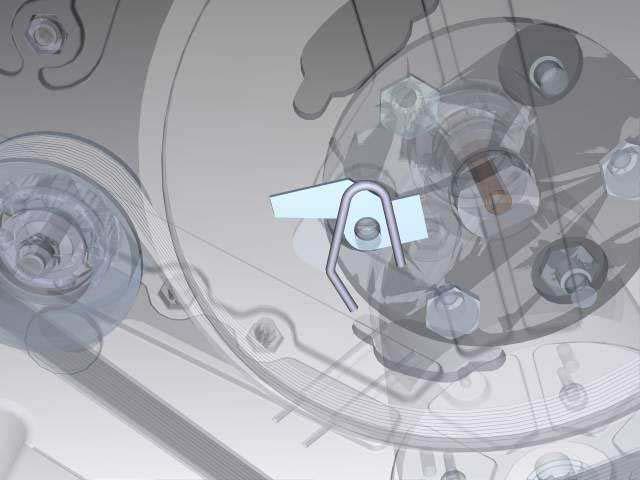
7 MACHINE PREPARATION 7. CONNECTION OF THE BATTERY CONNECTOR The battery connector (2) has to be connected to the connector of the machine (1) BATTERIES INDICATOR (machines with traction) The batteries indicator is digital with 4 fixed positions and a blinking one. The numbers, which appear on the display, show the approximate charge level. 4 = maximum charge, 3 = charge 3/4, 2 = charge 2/4, 1 = charge 1/4, 0 = (blinking) discharged batteries) ATTENTION! Some seconds after that 0 blinks, the brush motor automatically switches off. Anyway, the machine can finish to dry before recharging the batteries. 9. SQUEEGEE ASSEMBLY The squeegee is supplied separately, dismantled from the machine, for packing reasons. It must be installed as illustrated, threading the retaining pin into the squeegee column. Put the aspiration tube into its sleeve. 10. ADJUSTMENT SQUEEGEE HEIGHT The squeegee has to be regulated depending on the wearing of the rubbers. To adjust this, rotate the knob (2) counterclockwise to lift the squeegee and clockwise to lower it. Note: The right and left wheels must be adjusted at the same amount so that the squeegee works in parallel to the floor. 10
 counterclockwise.")
 to lift the base (lever downwards). 2. Turn key (2) to OFF and remove it from the control panel. ATTENTION! installing the brushes with power on may cause injury to the hands 1.")
8 MACHINE PREPARATION 11. ADJUSTMENT SQUEEGEE INCLINATION During working operation, the rear rubber has to work slightly tilted backwards and this equally in its whole length for about 5mm. Should it be necessary to increase the rubber bending in the central part, then tilt the squeegee body backwards and turn the adjuster (1) counterclockwise. If the rubber bending is to be noticeable at the sides of the squeegee, turn the adjuster clockwise. At the end of the adjustment, block the adjuster nut. 12. MANUAL BRUSHES ASSEMBLY 1. Use lever (1) to lift the base (lever downwards). 2. Turn key (2) to OFF and remove it from the control panel. ATTENTION! installing the brushes with power on may cause injury to the hands 1. With the base raised thread the brushes into the seat on the plate below the base, turning them until the three buttons enter the holes on the plate. Turn them abruptly to push the button towards the retaining spring so that the brush locks in place. The photo shows the direction of rotation for installing the right brush. Rotate the opposite direction to install the left brush. For the single brush models the procedure is the same and the rotation direction for the brush coupling is the opposite of what indicated on the picture. (Only for double brush machines) We recommend inverting right and left brushes every day and vice versa. If brushes are not new and have distorted bristles then it is best to install them always in the same position (the right brush on the right side and the left brush on the left side) to prevent bristles with a different slope from overloading the brush motor and causing excess vibrations. 11
9 MACHINE PREPARATION 13. ASSEMBLY CYLINDRICAL BRUSHES 1. Brake the machine acting upon the lever (1) 2. Lift the brush base acting upon the lever (2) 3. Turn the key (1) into position 0 and take it of 4. Remove the lateral right splash guard (see DISASSEMBLY AND CLEANING OF THE BRUSH UNIT) ATTENTION! Use gloves for this operation in order to protect your hands 1. Insert the brush in the tunnel (Side with 5 teeth) until it is coupled with the traction hub 2. Insert the free hub (1) of the mobile support into the brush (side with 6 teeth) 3. Repeat the operation for the second brush 4. Assemble the lateral splash guards (2) RECOVERY TANK Open hood (1). Check: 1. that plug (2) is properly anchored (it must not pull out when it is lifted, otherwise turn it clockwise); 2. that aspiration tube (3) is inserted in its seat. 15. SOLUTION TANK Fill the solution tank with clean water at a temperature not in excess of 50 C. Add liquid detergent in the amounts and using the procedures recommended by the detergent manufacturer. Use only a minimal percentage of detergent to prevent formation of an excess quantity of foam since too much foam may damage the aspiration motor. ATTENTION! Always use low-foam detergent. Introduce a small amount of anti-foam detergent in the recovery tank before starting to work to be sure to prevent foam from being generated. Never use pure acids. 12
 a quarter turn clockwise. The battey led display immediately comes on. 5. Press brush switch (1). 6. Press aspiration switch (2). 7. Use knob (3) to adjust water flow. 8.")
, that the amount of water is sufficient and that the squeegee dries the floor perfectly.")
10 PERFORMANCE 1. SETTING FOR WORK 1. Set the machine up for operation. 2. Check that the parking brake is released (1). 3. Connect the connector to the batteries (2). 4. Turn the main switch key (3) a quarter turn clockwise. The battey led display immediately comes on. 5. Press brush switch (1). 6. Press aspiration switch (2). 7. Use knob (3) to adjust water flow. 8. Push the lever (1) to lower the base. 9. Pushing the lever, lower the squeegee assembly (2). 9. (Only machines with traction motor) The machine will start to move when deadman lever (1) is pushed forward. Check, during the first few meters of wash, that brush pressure is adequate (see "BRUSH PRESSURE" below), that the amount of water is sufficient and that the squeegee dries the floor perfectly. The machine will now start to work at full efficiency until the solution water is finished. Immediately apply emergency brake (2) on the left side of the machine whenever problems arise during operation. This control stops forward movement by the machine. To start to work again, after solving the problem, just raise level (2) and push deadman lever (1) forward. 13
11 PERFORMANCE 2. OVERFLOW DEVICE The machine is equipped with a float, which intervenes when the recovery tank is full causing the closure of the suction hose. In this case, it is necessary to proceed with the emptying of the recovery tank taking off the plug of the exhaust pipe. ATTENTION! This operation has to be carried out using gloves to protect from contact with dangerous solutions. 3. BRUSH PRESSURE Use lever (1) to adjust brush pressure. There are three preset positions. The greatest pressure is when the lever is in its highest position. Pressure should be selected depending on the type of floor and the amount of dirt. Too much pressure causes increased brush wear and greater energy consumption. 4. MOVEMENT (machines with traction) These machines are equipped with electronically commanded traction, with two speeds forwards and one backwards. To move the machine, it is necessary to act upon the key (1), wait for three seconds and then rotate forward (forward movement) or backward (rear movement) the lever (2) on the handle bar. Pushing forward the lever a few millimetres, the first speed is available, pushing the lever forward completely, the second speed is obtained. In reverse motion, the speed movement is reduced. WARNING! When carrying out even short backward movements, make sure that the squeegee is lifted. 5. BRAKES (machines with traction) The machine has two braking systems: a working electronic brake integrated in the drive system (1) and an emergency brake which works by pushing downwards the lever (2), which works also as parking brake when it is fixed in the proper hooking down on the right. 14
. 6. Move the machine to the water disposal point. 7. Turn key (3) to turn the machine off. 8. Lift hood (1). This frees recovery tank drain tube (2). 9.")

12 ON COMPLETION OF THE WORK At the end of the work day, before performing any type of maintenance: 1. Close cock (3). 2. Raise base (1). 3. Raise squeegee (2) 4. Turn off brush switch 1). 5. Turn off aspiration motor switch (2). 6. Move the machine to the water disposal point. 7. Turn key (3) to turn the machine off. 8. Lift hood (1). This frees recovery tank drain tube (2). 9. Remove the drain tube from its seat, unscrew the drain plug and empty the recovery tank (Lift the left side of the tank a few centimeters to accelerate final emptying phases). These operations must be performed wearing rubber gloves to protect against contact with dangerous solutions. 10. The squeegee should be raised when the machine is not in use to prevent permanent distortion of the rubber strips. 11. Remove the brushes and clean them with a jet of water (see "BRUSH REMOVAL" below). ATTENTION! This operation has to be carried out using gloves to protect from contact with dangerous solutions. 12. Push the knob (1) toward the rearpart of the machine and unhook the splash guard. 13. Extract the hopper and clean it thoroughly. ATTENTION! This operation has to be carried out using gloves to protect from contact with dangerous solutions. 14. Lift the sweeping group on completion of the work to avoid brushes deformation. 1 15


13 DAILY MAINTENANCE 1. CLEANING RECOVERY TANK 1. Open the hood (1). 2. Remove the drain tube (2) from its seat. 3. Empty the tank through the drain tube by turning the knob a few turns and then pulling out the plug. ATTENTION! This operation has to be carried out using gloves to protect from contact with dangerous solutions. 1. Remove plug (1) from the recovery tank.. 2. Pull out the filter with its foam-protection unit. 3. Rinse the inside of the tank thoroughly with a jet of water. Slightly lift the tank, using its handle, to improve dirt removal. 4. Put the tank back in the machine and put the plug back on the drain tube. ATTENTION! This operation has to be carried out using gloves to protect from contact with dangerous solutions. 2. CLEANING THE SUCTION FILTER 1. Remove the suction unit from the tank. 2. Remove the black guard by making a circular movement (1). 3. Detach filter (2) and clean it carefully with a jet of water. 4. Reinstall everything by performing these procedures in reverse order CLEANING THE SQUEEGEE The squeegee must be in perfect working condition to achieve a good drying process: it must be clean and its rubbers must be in good condition. Proceed as follows to clean the squeegee: 1. Remove it from the machine by pulling pin (1) out from column (2). Clean the interior with a jet of water. 2. Loosen knobs (3), remove block (4) and check that there is no dirt inside. 3. Check the condition of the rubbers and replace them as necessary. 4. Replace everything on the machine. 16
14 DAILY MAINTENANCE 4. REPLACEMENT OF THE SQUEEGEE RUBBERS Check the squeegee rubber wear and if necessary, change them. To replace them: 1. Take off the suction hose from its coupling. 2. Take off the the pin from the stud bolt. 3. Remove the squeegee from its support. 4. Remove the wing nuts which block the rubber blades and take them off. 5. Replace the rubbers. 6. To reassemble the squeegee repeat the abovementioned operations. 5. MANUAL BRUSHES REMOVAL 7. Push lever (1) down to raise the base. 8. Turn key (2) to OFF and remove it from the control panel (removing the brushes with power on may cause injury to the hands). ATTENTION! During this operation make sure that, there are not any objects or persons close to the brush. 1. Rotate the brush, with the base raised, until it exits from the brush-bearing plate as illustrated. The picture shows the direction of rotation for releasing the right brush. Rotate in the opposite direction for the left brush 2. For single brush versions the procedure is the same and the rotation direction for brush release is the opposite of what indicated on the picture. ATTENTION! During this operation make sure that, there are not any objects or persons close to the brush. 6. DISASSEMBLY OF BRUSHES (Only scrubbing-sweeping models) To take off the brooms: 1. Lift the brush base acting upon the lever (2) 2. Brake the machine acting upon the lever (1) 17
 2.")
15 DAILY MAINTENANCE 3. Clean the hopper as under item 13, paragraph ON COMPLETION OF THE WORK 4. Make sure that, at the brushes ends nothing is coiled up like wires, plastic or anything else which does not allow the free brushes rotation. Otherwise: 1. Unscrew the wing nut (1) 2. Take off the plate (2) 3. Remove the splash guard (3) Take off the plugs (1) 5. Extract and clean the brushes. ATTENTION! Make sure that, during this operation the general key is turned into position BRUSH REMOVAL WITH AUTOMATIC COUPLING-RELEASE (Optional) Turn the brushes switch off and press the brushes/brush release button until the brushes release. 18
16 WEEKLY MAINTENANCE 1. CLEANING OF THE SQUEEGEE HOSE Weekly or whenever suction seems to be unsatisfactory check that the squeegee hose is not obstructed. Eventually, clean it proceeding as follows: 5. Take off the hose from its coupling on the squeegee 6. Take off the other end from the recovery tank. 7. Wash the inner part of the hose with a water jet introduced from the side where it is being connected to the tank. 8. To reassemble the hose repeat the above-mentioned operations inversely. ATTENTION! Do not wash the hose, which goes from the suction motor to the suction plug. 2. CLEANING SOLUTION TANK 1. Unscrew the plug on the solution tank 2. Rinse with a water jet 3. Unscrew the exhaust plug (1) and empty the tank ATTENTION! This operation has to be carried out using gloves to protect from contact with dangerous solutions. 19
17 TROUBLE SHOOTING GUIDE 1. INSUFFICIENT WATER ON TO THE BRUSH 4. Check that the cock is open (signal lamp on). 5. Check that there is water in the solution tank. 2. MACHINE DOES NOT CLEAN WELL 6. Check the condition of the brushes and replace if necessary (brushes must be replaced when bristles are 15 mm. high). 7. Check that brush pressure is sufficient. Increase as necessary using lever (1). 8. Use another type of brush rather than the standard brush. We recommend, to clean floors with exceptionally difficult dirt, the use of special brushes that are supplied on request and according to your specific needs (see "BRUSH SELECTION AND USE" below). 3. SQUEEGEE DOES NOT DRY PERFECTLY 1. Check that the squeegee is clean. 2. Check all adjustments (see "PREPARING THE MACHINE"). 3. Clean the entire aspiration unit (see "DAILY MAINTENANCE").. 4. Replace worn rubbers. 4. SUCTION MOTOR DOES NOT WORK 1. Check if the suction motor switch (1) is ON. Check if the main key switch is ON. 2. Check if the recovery tank is full. 5. TOO MUCH FOAM FORMATION 1. Check that low-foam detergent is used. Add, if necessary, a small quantity of anti-foam liquid to the recovery tank. Remember that more foam is generated when the floor to be cleaned is not very dirty. In this case use a more diluted detergent solution 20

18 SMALTIMENTO ATTENZIONE: Il prodotto, giunto a fine vita, deve essere conferito ai punti di raccolta differenziata messi a disposizione dell'utente finale. 21
19 CHOICE AND USE OF BRUSHES POLYPROPYLENE BRUSH (PPL) It is used on all types of floors which are hot water resistant (not more than 60 C). The Polypropylene brush is nonhygroscopic and therefore conserves its characteristics even if working in the wet conditions. NYLON BRUSH It is used on all types of floors with excellent wear and hot water resistance (more than 60 C). The nylon is hygroscopic and so, over time, looses its characteristics working on the wet. ABRASIVE BRUSH The brush bristles are charged with very aggressive abrasives. It is used to clean very dirty floors. To avoid floor damages, work strictly only with the necessary pressure. STEEL BRUSH The bristles are made of steel wires; it is used to descale floors which are anyhow resistant to the abrasion, very uneven or with wide joints. THICKNESS OF THE BRISTLES The thicker the bristles are, the more rigid they will be. These ones are therefore used on smooth floors or with small joints. On uneven floors with deep joints it is recommended that, softer bristles, which enter more easily in depth, are used. Please bear in mind that, when the bristles are worn out and get too short, they will get rigid and cannot penetrate anymore. As well as for thick bristles, the brush will begin to jump. PAD HOLDER The pad holder is recommended to clean glossy areas. There are two types of pad holders: 1. The traditional pad holder is equipped with anchor points, which allow the abrasive pad to be held and dragged during the work process. 2. The pad holder is of the CENTER LOCK type, apart from the anchor points, is equipped with a central blocking release system made in plastic. This allows a perfect match with the abrasive pad and to hold it without the risk of falling down. This type of pad holder is recommended especially for machines with more brushes, where the centering of the pads is difficult. LIST FOR THE CHOICE OF THE BRUSHES Machine Q.ty Code Bristles type Thick Brush Notes MAXIMA 450 MAXIMA 500 MAXIMA 452 MAXIMA 502 MAXIMA 650 MAXIMA 50BS-BTS PPL PPL PPL ABRASIVE Pad holder Center Lock PPL PPL PPL ABRASIVE Pad holder Center Lock PPL PPL PPL ABRASIVE Pad holder PPL PPL PPL ABRASIVE Pad holder PPL PPL PPL ABRASIVE Pad holder PPL WHITE PPL LIGHT BLUE ABRASIVE GREY Pad blocking Pad blocking Pad blocking 110x x x500 Front brush more rigid Rear brush Front brush 22
20 CE STATEMENT OF COMPLIANCE model Maxima 450/500/452/502/650/50 The undersigned company: FIMAP S.p.A. Via Invalidi del Lavoro n Santa Maria di Zevio (VR) states under its own exclusive responsibility that the product FLOOR SCRUBBING MACHINE model Maxima 450/500/452/502/650/50 complies with the provisions of Directives: 98/37/EEC: Machine directive. 89/336/EEC: Electromagnetic compatibility directive and following modifications 91/263/EEC, 92/31/EEC and 93/68/EEC. Inoltre è conforme alle seguenti norme: EN : Safety of electric home appliances and the like Safety. Part 1: General regulations. EN : Safety of electric home appliances and the like. Part 2: Special regulations for automatic machines for processing industrial and community-use floors. EN : Machine safety Basic concepts, general design principles Part 1: Base terminology and methodology. EN : Machine safety Basic concepts, general design principles Part 2: Technical principles. EN : Electromagnetic compatibility (EMC) - Part 6-3: General standards Emission for residential, commercial and light industrial environments. EN : Electromagnetic compatibility (EMC) - Part 6-1: General standards Immunity for residential, commercial and light industrial environments. EN 50366: Appliances for home use and the like Electromagnetic fields Evaluation and measurement methods. Santa Maria di Zevio, 05/02/2007 FIMAP S.p.A. Legal Representative Giancarlo Ruffo FIMAP spa Via Invalidi del Lavoro, S.Maria di Zevio (Verona) Italy Tel r.a. - Fax fimap@fimap.com
21
22 Item Applies To SKU Description QTY 1 E83524 Bushing 1 2 E83895 Wheel B-BT BLADE 1 3A 500 B-BT E86169 Band Clamp B-BT E83653 Splash guard 1 4A 500 B-BT E86197 Skirt, Brush Rubber 1 5 E82312 Bushing 2 7 E81772 Special Washer 1 8 E81659 Spring 1 9 E81769 Shaft 1 10 E81771 Bearing, RS 2 11 E82667 Belt 1 12 E83491 Spring, 2 13 E83489 Rings B-BT SUPPORT 1 14A 500 B-BT SUPPORT 2 15 E82411 Pulley, Simpla 1 16 E83496 Cord strain relief 1 17 E86273 Spacer SCREW BASE 1 20 E82260 Carbon Brush CARBON BRUSH HOLDER DOWEL 1 23 E83700 Shaft Key 5x5x20mm 1 24 E81822 Cable, 1 25 E83698 Tension Spring BRACKET 1 27 E82424 Pulley, BUSHING 1 29 E83277 Bearing, RS CUPPED WASHER REGISTER 1 32 E81660 Spring 1 33 E88043 Dowel M6 x E82738 Brush Motor 24VDC 560W NUT M24 UNI WASHER M24 UNI SCREW M8X40 UNI WASHER M8 UNI WASHER M8 D.32 UNI LOCK NUT M8 UNI SCREW M6X30 UNI NUT M6 UNI NUT M5 SERPRESS 59 - SCREW M5X20 UNI 5739 A LOCK WASHER M8 D.24 UNI LOCK WASHER M8 DIN 6798/A 62 - LOCK WASHER M8 SCHNORR 63 - SCREW M8X20 UNI SCREW M6X35 UNI E86701 NUT M6 A GABBIA 66 E83831 SCREW M6X20 UNI 5933 A WASHER M14 UNI 6592 OTTONE 68 - SCREW M6X18 UNI LOCK WASHER M6 DIN 6798/A 70 - WASHER M6 D.18 UNI SCREW M6X16 UNI NUT M8 UNI SCREW M8X55 UNI NUT M12X1.25 UNI SCREW M8X25 UNI SCREW M6X18 UNI 5739
23
24 ITEM Applies To SKU Description QTY ITEM Description 1 B-BS E81737 Axle NUT M16x1,5 UNI B-BS WHEEL WASHER M8 UNI B E86175 Support NUT M8 UNI A BS SUPPORT SCREW M8x16 UNI E82529 Caster, Rear Abila SCREW M8x18 UNI A 45 BS-BTS WHEEL WASHER M8 SCHNORR 5 BT-BTS E82395 Washer WASHER M20 UNI BT-BTS E82542 Drive Wheel 175 OD x 45 W NUT M10 UNI BT-BTS E82736 Washer SCREW M10x25 UNI BT-BTS AXLE-SHAFT WASHER M6 UNI BT-BTS E88191 Flange Bearing NUT M6 UNI BT-BTS GEARMOTOR SCREW M8x20 UNI BT-BTS AXLE-SHAFT WASHER M8 DIN 6798/A 12 BT-BTS E82375 Shroud cover, motor NUT M8 UNI BT-BTS SPLASH GUARD WASHER M10 UNI BT-BTS BUSHING SCREW M10X35 UNI BT-BTS SUPPORT SCREW M6X16 UNI BT-BTS E81778 Spring WASHER M6 D.18 UNI BT-BTS PAD SCREW M8X22 UNI BT-BTS SHAFT FRAME CARBON BRUSH MOTOR SPLASH GUARD 1
25
26 ITEM SKU DESCRIPTION QTY 1 E81935 Hose 1 2 E83810 Knob 2 3 E82707 Set Screw Hex 2 4A E82676 Band Clamp 31 1/4" x 7/8" x 1/8" 1 5A E12560 Squeegee Blade, Polyurethane 1 6A E12686 Squeegee Blade, Gum Rubber 1 7A E88240 Squeegee Body 1 8A E83909 Squeegee Blade, Polyurethane 1 9A E82608 Band Clamp 29 1/2" x 7/8" x 1/8" 1 10 E83531 Knob 2 11 E82329 Threaded Pin 2 12 E82428 Wheel 52 OD x 28 W 2 13 E82273 Bushing 2 14 E85497 Weldment, Squeegee Wheel Suppo 2 15 E81634 Spring Compression 2 16 E85498 E Style Circlip 1 17A BLADE 1 18 E83862 Seeger Ring, Media 2 19 E82377 Joint 1 20A BLADE WHEEL ASSEMBLY COUPLING 1 23 E83331 Knob, M8 Round Nylon Female 1 24 E83655 Adjuster Knob 1 25 E83911 Stud Bolt M10x46 Custom 1 26 E83590 Chain 1 27 E83591 Knob, M6 2-Arm Nylon Female 2 28 E82451 Wheel 45 OD x 25 W 2 29 E82253 Bushing, Brass 2 30 E83971 Gasket 1 31 E82307 Squeegee Vacuum Adapter 1 E81858 Squeegee ASM, 30" Parabolic 50 - SCREW M6X20 UNI 5739 A LOCK NUT M6 UNI NUT M6 UNI 5588 A WASHER M6 UNI 6592 OTTONE WASHER M6 D.18 UNI WASHER M12 UNI SCREW M6X50 UNI SCREW M6X25 UNI WASHER M6 UNI NUT M10 UNI SCREW M10X50 UNI SCREW M10X25 UNI WASHER M8 UNI SCREW M8X30 UNI SCREW M6X25 UNI 5933 A2 -
27
28 ITEM SKU DESCRIPTION QTY TUBE CLAMP 7 3 E81454 Barbed Elbow SUPPORT 1 5 E82366 Valve TUBE 1 7 E88400 Fitting 1 8 E86178 O-Ring 2 9 E83118 Solution Housing Assembly 1 10 E83119 solution supply filter 1 11 E82341 Gasket TUBE 1 13 E87297 Valve Shaft CLAMP 1 15 E83164 Micro Switch 1 16 E88085 Fitting 1/2 x 3/ E81035 Solenoid Valve 1 18 E82269 Barbed Fitting, 3/8 in DOWEL SUPPORT 1 21 E85762 Hose Clamp 1 22 E86251 Nipple 1 23 E85760 Gromment SCREW M6X16 UNI WASHER M20 UNI NUT M6 UNI SCREW M6X20 UNI LOCK WASHER M6 UNI LOCK NUT M8 UNI SCREW M8X70 UNI NUT M5 UNI LOCK NUT M3 UNI SCREW M3X20 UNI 5739 A WASHER M6 UNI
29
30 ITEM QTY DESCRIPTION QTY TUBE CLAMP 6 3 E81454 Barbed Elbow SUPPORT 1 5 E82366 Valve TUBE 1 7 E88400 Fitting 1 8 E86178 O-Ring 2 9 E83118 Solution Filter Assembly 1 10 E83119 solution supply filter 1 11 E82341 Gasket TUBE 1 13 E87297 Valve Shaft Foreman CLAMP 1 15 E83164 Micro Switch 1 16 E88085 Fitting 1/2 x 3/ E81035 Solenoid Valve 1 18 E82269 Barbed Fitting, 3/8 in DOWEL SUPPORT SCREW M6X16 UNI WASHER M20 UNI NUT M6 UNI SCREW M6X20 UNI LOCK WASHER M6 UNI LOCK NUT M8 UNI SCREW M8X70 UNI NUT M5 UNI LOCK NUT M3 UNI SCREW M3X20 UNI 5739 A WASHER M6 UNI
31
32 ITEM SKU DESCRIPTION QTY ARM 1 2 E83932 Bushing 9 3 E85767 Bushing 2 4 E82309 Spring, 11.8x1.2x15mm ARM KNIFE STUD BOLT 2 8 E82837 Spring 1 8A E82837 Spring KNIFE TIE ROD RETURN HANDLE 1 13 E81318 Knob 1 14 E83832 Flat Washer M8.5x30x E81714 Spring WASHER M8 D.24 UNI SCREW M8X25 UNI WASHER M8 DIN 6798/A SCREW M8X40 UNI NUT M8 UNI NUT M8 UNI SCREW M8X30 UNI SCREW M8X45 UNI SCREW M8X20 UNI SCREW M8X90 UNI WASHER M8 UNI SCREW M8X25 UNI SCREW M6X20 UNI NUT M6 UNI SCREW Ø 4,8X13 UNI SCREW M8X35 UNI

33 Recovery Drain Hose Solution Drain Hose
34 ITEM SKU DESCRIPTION QTY ITEM SKU DESCRIPTION QTY 1 E83850 Flat Washer M5x20 SS 6 32 E81710 Hose Clamp COVER 1 35 E88384 Fitting, Recovery Tank Hose 1 2A COVER 1 38 E82790 Air Filter/Shutoff PANEL 1 40 E88102 Recovery Filter Assembly 1 4 E86195 Cover, Bonnet Gray 1 41 E81786 Hose Clip 1 5 E88125 Bushing Foreman 4 42 E86290 Drain Hose 1 6 E88126 Bracket Foreman EXHAUST PIPE - 7 E81029 Hinge 2 43 ASSEMBLY/WATER LEVEL SPLASH GUARD SCREW M5X16 UNI BLADE SCREW M4X25 UNI 5739 A COVER LOCK NUT M4 UNI TANKS SCREW M8X45 UNI CLAMP LOCK NUT M8 UNI E86108 Drain Hose w/ Cap NUT M8 UNI CLAMP WASHER M8 UNI BRACKET SCREW M5X20 UNI E81887 Exhaust Plug LOCK NUT M5 UNI TANKS WASHER M5 D.15 UNI E87295 Tube (Pipe) Foreman SCREW M5X16 UNI Filter Assembly SCREW M6X14 UNI E81006 Vacuum Splash Guard SCREW M5X20 UNI 7687 A2-21 E83696 Filter CRS/DRS WASHER M5 UNI 6592 A2-22 E83338 Float WS SCREW M6X16 UNI E83605 Split pin WASHER M6 D.18 UNI E83995 Ring WASHER DIN 6798/A - 25 E88284 Washer 4 x 8 x 3 Nylon SCREW M6X35 UNI E82381 Gasket Ring SCREW Ø 3.9X13 UNI E82450 Cover SCREW Ø 4.2X16 UNI E83994 Gasket WASHER M5 D.20 UNI E82267 Coupling SCREW M5X25 UNI E20462 Hose, Vacuum NUT M4-31 E85756 Recovery Tank Lid Assembly WASHER M6 D.24 -
35
36 ITEM SKU DESCRIPTION QTY COVER 1 2 E82493 Grips, Handle PIPE 2 4 E81019 O-Ring 2 5 E82782 Washer 2 6 E85751 Trigger Lever for Simpla SHAFT SUPPORT PLATE 2 9 E82304 Spring, 20.2x1.3x20.8mm Steel Torsion WASHER 1 11 E82284 Lever HANDLE BAR BODY 1 13 E81663 Fair Lead 1 14 E88192 Nut SUPPORT PLATE 2 16 E83701 Spring pin BRACKET 1 18 E82794 Microswitch BRACKET CABLE 1 21 E83584 Battery jumper cable D/CRS 1 22 E83254 Female connector lug (Fr.) 1 23 E86208 SB50 Red Electrical Connector SCREW Ø 4.8X32 UNI SCREW M3X LOCK NUT M3 UNI SCREW Ø 4.8X LOCK NUT M6 UNI WASHER M6 UNI SCREW M6X20 UNI WASHER M8 UNI LOCK WASHER M SCREW M8X20 UNI SCREW M3X20 UNI SCREW Ø 4.8X LOCK WASHER M5 -
37
38 ITEM SKU DESCRIPTION QTY ITEM SKU DESCRIPTION QTY PROTECTION INSTRUMENT BOARD 1 2 E83168 Fuse, 3 amp BASE 4 3 E88244 Fuse Holder for Crewman AS20B 1 23 E83495 Hour Meter SUPPORT PLATE SCREW M4X10 UNI E83926 Fuse 30A faston suction motor WASHER M4 D.12 UNI E86196 Fuse, 60 amp NUT M4 AUTOBL. UNI E81642 Fuseholder SCREW M4X12 UNI E88497 Fuse Block End Cap WASHER M8 UNI PANEL SCREW M5X12 UNI E82403 Double remote control SW 24V WASHER M5 UNI E83160 Relay 24VDC 30A NUT M5 AUTOBL. UNI LABEL WASHER M5 DIN 6798/A - 13 E87975 Stud Bolt Tripla WASHER M5 D.15 UNI E86145 Knob NUT M4 UNI E81706 Signal Lamp Green SCREW 4.8X13 UNI E83328 Vacuum switch SCREW M4X8 UNI E88022 Battery Check Card 24 Volt SCREW M3X16 UNI 7687 A PLUG SCREW 5.5X10 UNI E82379 Switch NUT M3 AUTOBL. UNI GREEN PUSH BUTTON SCREW 4.2X13 UNI
39
40 ITEM SKU DESCRIPTION QTY ITEM SKU DESCRIPTION QTY PROTECTION 2 26 E82379 Switch 1 2 E83168 Fuse, 3 amp GREEN PUSH BUTTON 1 3 E88244 Fuse Holder BASE SUPPORT PLATE 1 29 E83495 Hour Meter 1 5 E83926 Fuse 30A faston 1 30 E83495 Hour Meter 1 6 E86196 Fuse, 60 amp 1 31 E83315 Switch Key 1 7 E81642 Fuseholder SCREW M4X10 UNI E88497 Fuse Block End Cap WASHER M4 D.12 UNI ELETTRICO PANEL LOCK NUT M4-10 E82403 Double remote control SW 24V SCREW M4X12 UNI E83160 Relay 24VDC 30A WASHER M8 UNI E83972 Fuse 30A fasten SCREW M5X12 UNI E83159 Relay 24VDC 20A WASHER M5 UNI E20646 Chopper Card LOCK NUT M BRAKING Resistor NUT M4 UNI E83173 Contact, Key Switch WASHER M5 D.15 UNI E81358 Switch Flange LOCK WASHER M Label SCREW M5X16 UNI E87975 Stud Bolt SCREW M5X30 UNI E86145 Knob WASHER M5 D.20 UNI E81706 Signal Lamp Green LOCK NUT M3-22 E83328 Vacuum switch SCREW M4X8 UNI INSTRUMENT BOARD SCREW M3X16 UNI E88022 Battery Check Card 24 Volt SCREW 5.5X10 UNI E83316 Key Switch SCREW 4.8X13 UNI SCREW 4.2X13 UNI
41
42 ITEM SKU DESCRIPTION QTY 1 E81477 Knob 25X50 M8 1 2 E82550 Handle - Lever S BUSHING LEVER 1 5 E85768 Squeegee Cable 1 6 E81907 Pin SHAFT CABLE 1 9 E86154 Fork BRACKET PIN LOCK NUT M6 UNI SCREW M6X16 UNI LOCK WASHER M SCREW M6X20 UNI NUT M6 UNI SCREW M5X16 UNI WASHER M6 D.18 UNI NUT M5 UNI LOCK WASHER M WASHER M5 D.15 UNI
43
44 ITEM SKU DESCRIPTION QTY 1 E81477 Knob 25X50 M HANDLE 1 3 E82550 Handle - Lever S BUSHING LEVER 1 6 E85768 Squeegee Cable 1 7 E81907 Pin SHAFT SPACER CABLE 1 11 E86154 Fork CABLE 1 13 E86154 Fork BRACKET PIN LOCK NUT M6 UNI SCREW M6X16 UNI SCREW M6X30 UNI WASHER M6 DIN 6798/A SCREW M6X20 UNI NUT M6 UNI SCREW M6X20 UNI WASHER M6 D.18 UNI NUT M5 UNI LOCK WASHER M WASHER M5 D.15 UNI
45
46 ITEM SKU DESCRIPTION QTY DEADENING HOSE 1 2 E83920 Clamp 9x300 4,8x360 black 1 3 E83949 Motor, Vacuum 1 3A E82631 Motor, Vacuum 36v 720w 2-Stage SUPPORT 1 5 E83944 Sound Deadening Foam STUD BOLT 3 7 E87975 Stud Bolt Tripla SPACER 3 9 E83244 deadening hose 1 10 E83871 Compression spring 55x2x DEADENING HOSE COVER DEADENING HOSE DEADENING HOSE 1 15 E88291 Vacuum Motor 36VDC 550W 1 16 E83944 Sound Deadening Foam 1 17 E82282 Sound Deadening Foam STUD BOLT LOCK NUT M NUT M6 UNI SCREW M6X80 UNI SCREW M6X120 UNI SCREW Ø 4,8X WASHER M6 D.18 UNI WASHER M6 UNI SCREW M6x90 UNI
47
48 ITEM SKU DESCRIPTION BUTTON - BRUSH- COUPLING 2 E82379 Switch 3 E83316 Key Switch E81358 Switch Flange E83173 Contact, Key Switch 4 E88022 Battery Check Card 24 Volt 5 E83328 Vacuum switch 6 E81706 Signal Lamp Green 7 E83164 Micro Switch 8 E82520 Potentiometer 9 E82794 Microswitch 10 E82794 Microswitch 11A E82403 Double remote control SW 24V 11B 12 E83160 Relay 24VDC 30A 14 E83168 Fuse, 3 amp 15 E83972 Fuse 30A fasten 16 E83159 Relay 24VDC 20A 17 E83159 Relay 24VDC 20A 18 TRIMMER REGULATION MIN.SPEED 19 TRIMMER REGULATION ACCELERATION 20 TRIMMER REGULATION MAX. SPEED 21 E20646 Chopper Card 22 E86196 Fuse, 60 amp 23 E83926 Fuse 30A faston suction motor 24 E86208 SB50 Red Electrical Connector 25 E86208 SB50 Red Electrical Connector SOLENOID VALVE (OPT.) 27 E83495 Hour Meter M1 E82738 Brush Motor 24VDC 560W M2 E83949 Motor, Vacuum M2 E82631 Motor, Vacuum 36v 720w 2-Stage M TRACTION MOTOR 24V
49
50

 5.")
 onto the faston M+ and M- of the chopper card Switch on through the general key Adjust trimmer ACC (acceleration) rotating the left")
51 ADJUSTMENTS AND INSPECTIONS MAXIMA Doc Emesso dec -06 Rev. 00 Pag. 1 di 7 ADJUSTMENTS AND INSPECTIONS / ALL MODELS READ THE OPERATING AND MAINTENANCE MANUAL Inspection Electrical Equipment 1. Check functionality electrical equipment: switches, motors, solenoid valve. 2. Check functionality control coupling-uncoupling brush, where this is assembled. 3. Check the condition of the fuses placed behind the rear grey panel 4. Check functionality chopper (traction machine) 5. If necessary set the chopper card proceeding as follows: Lift the machine (traction wheels must be free) Take off the rear screws to open the panel; take off the fixing screw and lower the complete electric group Insert the tester prods (V-DC) onto the faston M+ and M- of the chopper card Switch on through the general key Adjust trimmer ACC (acceleration) rotating the left screw up to the end, then position it on Press onto the lever placed on the handle bar in forward movement, until the release of the drive relay is heard, then stop. 7. Adjust the trimmer Vmin (minimum) until the value on the tester is read, which is between 3-5 V.
, until")


52 ADJUSTMENTS AND INSPECTIONS MAXIMA Doc Emesso dec -06 Rev. 00 Pag. 2 di 7 8. Push the lever on the handle bar completely forward, read on the tester the tension value: this should be equal to the battery tension, otherwise act upon the trimmer Vmax (maximum voltage), until the tester indicates the correct value. 9. Recheck the minimum values with the trimmer Vmin. Bring the lever back to try the drive: check that the measured tension is less than the maximum value. 10. Check the motor braking releasing the drive: the machine must stop within 1 metre. Inspection Water Supply 1. Check the cleanness of the transparent solution filter. Check also eventual water leakages. 2. Fill completely with water the solution tank. 3. Check the tightness of the hoses, the solenoid valve* and the complete opening and closing of the water cock. * THE SOLENOID VALVE IS AVAILABLE ONLY ON MACHINES WITH KIT 4. Check that the detergent solution, when the cock is open, arrives with continuity onto the floor. 5. With the closed cock, check that there are not any solution leakages Inspection Suction 1. Check the cleanliness and functionality of the filter float. 2. Check the air seal of the cover on the recovery tank. 3. Check the connections and their tightness of the suction hoses and the squeegee hose. 4. Check the tightness of the hose and of the exhaust plug.


53 ADJUSTMENTS AND INSPECTIONS MAXIMA Doc Emesso dec -06 Rev. 00 Pag. 3 di 7 Adjustment brush SINGLE BRUSH B-BT / MOVEMENT SEMI-AUTOMATIC B 1. Adjust the spring belt tightener at a length of 27mm (1,06 inches) in compression. 2. The adjustment lever for the height of the brush base placed under the machine, has to be adjusted always with the brush base lowered onto the floor, without the brush. Check that the lifting lever is in the highest point of the sliding slit, without hitting or forcing onto the frame. Furthermore, check that it slides to the right and to the left, with the lever stop being free. 3. To get the correct functioning, act upon the screw M8 placed on the lever under the machine, by screwing down or unscrewing until the rear lever is brought into its correct position, then block the lock nut M8. 4. The brush adjustment for the machines without traction and therefore with a movement depending on the brush rotation, has to be carried out as follows: Lower the brush base, applying in the front part of the cover a metal bar of 15mm between the cover and the floor, and unscrew the screw M6 on top of the cover. Unscrew the screw M8 of the brush inclination, push the complete base downwards and block the screw previously unscrewed, screw down the screw M6 until it touches lightly the base. Couple the brush, always with the brush base in working position, and unscrew the screw M8 for the brush inclination, then block the screw as soon as the brush base fixing is obtained. Adjust the traction effect on hand of the screw M6, then block the lock nut.


, and block it as soon as the correct base adjustment is")
54 ADJUSTMENTS AND INSPECTIONS MAXIMA Doc Emesso dec -06 Rev. 00 Pag. 4 di 7 Adjust the cup head screw brush rest until the head just touches the even part of the brush on which it rests. The allowance between the head of the screw and the brush must be at most 1mm-2mm, when the brush is coupled and lowered. 5. For the models with automatic traction apply the metal bar which should be brought to 25mm in the front part, loosen the screw M8 of the base inclination and after having noticed the correct base adjustment, block the screw again. 6. Take off the metal bar and couple the brush, loosen the screw M8 of the brush base inclination, after having noticed its correct adjustment, then block the screw. Adjust the screw M6 placed on top of the brush cover, with the brush functioning, in order that the machine does not move. 7. Block the lock nut M6. Adjustment brush and base - G B-BT / MOVEMENT SEMI-AUTOMATIC B For the machines B, that means with a semi-automatic movement, which depends on the brushes rotation, in case the machine should not have a straight movement, or should this be insufficient, carry out the following operations: 1. With brush base lowered, complete with its brushes, unscrew the screw M8 on the right (screw brush base inclination), and block it as soon as the correct base adjustment is noticed. This operation is necessary to eliminate eventual defects of the machine movement. 2. If the traction has be increased or reduced, operate on the plaque on top of the brush base, loosening the nut M10. Unscrewing the screw a reduction of the traction is obtained, while screwing down more an increase of the traction is given. PS: DO NOT MODIFY EXCESSIVELY THE TRACTION CHARACTERISTICS, OTHERWISE THE BRUSHES DO NOT FUNCTION CORRECTLY.

 in case there isn t an uniform adherence of the brushes on the floor so a")

 Bring the machine on a dry levelled surface Lower the sweeping system until the cylinder touch the floor.")
55 ADJUSTMENTS AND INSPECTIONS MAXIMA Doc Emesso dec -06 Rev. 00 Pag. 5 di 7 3. The dimension of the spring belt tightener should be always of 27mm in compression. The models equipped with automatic traction, that means BT, carry out the same operation what the brushes inclination concerns. PS: As the brushes are assembled on flexible couplings, with automatic traction, these models do not need other adjustments regarding the brushes group. Adjustment sweeping system 50BS BTS semiautomatic drive BS For the BS types (semiautomatic drive) in case there isn t an uniform adherence of the brushes on the floor so a incomplete cleaning function act as: lower the sweeping system Unscrew the right M8 screw Let the cylinders adhere equally to the floor Block the M8 screw Adjust the traction power, put the inclination lightly in the front part the deck and block the M8 screw. For the automatic traction types (BTS) make the same adjustment for a complete equal cylinder adherence, then check the work surface of both cylinders. Wet a little the cylinders (with water) Bring the machine on a dry levelled surface Lower the sweeping system until the cylinder touch the floor. Rise the cylinders and check the imprint left. It has to be a rectangle and uniform on both sides In case you have to modify the set up of the system, unscrew the M8 at the left of the sweeping system, adjust the deck in the parallel position, so block the screw


56 ADJUSTMENTS AND INSPECTIONS MAXIMA Doc Emesso dec -06 Rev. 00 Pag. 6 di 7 To help the disassembly of the cylindrical brushes, unscrew the screw until the lever is at the first hole of the pressure adjustment. Adjustment brushes base 1. Assemble the joint chain of transmission so that a distance of 2 mm. between two hubs is obtained and tyre toothed star is between two hubs, works correctly, avoiding vibration and shift. 2. Fix dowels and adjuster nuts. 3. Check tension of transmission belt working of screw M8, so that the thread goes out from support of about mm. Adjustment of the brake 1. Adjustment brake pads: check the braking uniformity, with the brake inserted, trying to rotate the machine both right and left, checking that the wheels remain blocked in the same way. 2. Adjust the range of the brake handle acting upon the two adjusters of the brake cable, one placed under the frame and the other one behind the electric panel. Adjustment Squeegee 1. Adjust the inclination register of the rear squeegee rubber when the squeegee is in function, so that this has an even bending. Block through the adjuster nut.

57 ADJUSTMENTS AND INSPECTIONS MAXIMA Doc Emesso dec -06 Rev. 00 Pag. 7 di 7 2. Adjust the height of the wheels with the suitable hand wheels checking that the rubber has an inclination of around and that it is not too much pressed down onto the floor nor too much lifted. 3. Check that the wheels of the squeegee support are in working position, that is to say that they touch the floor. Final inspection Check all the functions: washing, drying, forward and backward movement
To Order Parts Call
 5 SUMMARY ON CONSIGNMENT OF THE MACHINE...6 INTRODUCTORY COMMENT...6 TECHNICAL DATA...6 SYMBOLOGY USED ON THE MACHINE...7 SYMBOLOGY USED IN THE MANUAL...9 MACHINE PREPARATION...30. HANDLING OF THE PACKED
SYMBOLOGY USED ON THE MACHINE
 SUMMARY ON CONSIGNMENT OF THE MACHINE...34 INTRODUCTORY COMMENT...34 TECHNICAL DATA...34 SYMBOLOGY USED ON THE MACHINE...35 MACHINE PREPARATION...38 1. HANDLING OF THE PACKED MACHINE...38 2. HOW TO UNPACK
Tornado Operations & Maintenance Manual
 TORNADO INDUSTRIES 7401 W. LAWRENCE AVENUE CHICAGO, IL 60706 (708) 867-5100 FAX (708) 867-6968 www.tornadovac.com Tornado Operations & Maintenance Manual MODEL NO. 99690 BD 22/14, 99720 BD 26/14 L9722
AS20B CREWMAN. 20 Automatic Scrubber with Brush Assist. Operator Manual E E E
 E83025-00 E29936-00 E29937-00 CREWMAN AS20B 20 Automatic Scrubber with Brush Assist Operator Manual 400 Van Camp Road Bowling Green, Ohio 43402 Customer Service: 888-GO-BETCO Fax: 800-445-5056 Technical
Tornado Operations & Maintenance Manual
 TORNADO INDUSTRIES 7401 W. LAWRENCE AVENUE CHICAGO, IL 60706 (708) 867-5100 FAX (708) 867-6968 www.tornadovac.com Tornado Operations & Maintenance Manual MODEL NO. 99760 BD26/30 & 99780 BD33/30 L9718AB
jade 50 jade 55 jade 66
 jade 50 jade 55 jade 66 01 2015 Use and maintenance Attention! Please read the instructions before use. COD. 65302007 TECHNICAL DESCRIPTION U/M jade 50 jade 55 jade 66 Cleaning width Squeegee width Working
ruby 45t ruby 50t ruby 50bh ruby 55t
 ruby 45t ruby 50t ruby 50bh ruby 55t 01 2015 Use and maintenance Attention! Please read the instructions before use. COD. 65301008 TECHNICAL DESCRIPTION U/M ruby 45t ruby 50t ruby 50bh ruby 55t Cleaning
Tornado Operations & Maintenance Manual
 Tornado Industries, LLC 333 Charles Court West Chicago, IL 60185 www.tornadovac.com Tornado Operations & Maintenance Manual MODEL NO. 99414 Form No. L9740AB Tornado Industries, LLC. All rights reserved
ScrubMaster 26C OPERATING & MAINTENANCE
 ScrubMaster 26C INTRODUCTION OPERATING & MAINTENANCE INSTRUCTIONS READ THIS BOOK This operator s book has important information for the use and safe operation of this machine. Read this book carefully
Parts and Service Manual
 Section II Parts and Service Manual (70241A) CLARKE TECHNOLOGY Operator's Manual - MINI MAX Page -29- Frame and Front Cover Assembly Drawing 2/01 Page -30- CLARKE TECHNOLOGY Operator's Manual -MINI MAX
OWNERS MANUAL ST900 SERIES
 OWNERS MANUAL ST900 SERIES 1205 Britannia Road East, Mississauga, ON L4W 1C7 Phone: 1-800-387-3210 Fax: 1-800-709-2896 ON CONSIGNMENT OF THE MACHINE When the machine is consigned to the customer, an immediate
opal 66 opal 80 COD Use and maintenance Attention! Please read the instructions before use.
 opal 66 opal 80 09 2014 Use and maintenance Attention! Please read the instructions before use. COD. 65314001 TECHNICAL DESCRIPTION U/M opal 66 opal 80 Cleaning width Squeegee width Working capacity, up
ScrubMaster 30R OPERATING & MAINTENANCE
 ScrubMaster 30R INTRODUCTION OPERATING & MAINTENANCE INSTRUCTIONS READ THIS BOOK This operator s book has important information for the use and safe operation of this machine. Read this book carefully
ASD20B STEALTH. 20 Automatic Scrubber with Brush Assist. Operator and Parts Manual E E E
 E87030-00 E88062-00 E29935-00 STEALTH ASD20B 20 Automatic Scrubber with Brush Assist Scan this QR code to view equipment page Operator and Parts Manual 400 Van Camp Road Bowling Green, Ohio 43402 Customer
MANUAL USE AND MAINTENANCE FLEXY 75B-85B ED Doc Ver. AB
 MANUAL USE AND MAINTENANCE FLEXY 75B-85B ED. 03-2009 EN Doc. 10015846 Ver. AB The contained descriptions in the present publication are not binding. The company therefore reserves itself the right to bring
ASC20BT STEALTH. 20" Cylindrical Scrubber with Traction Drive. Operator and Parts Manual E E E
 E29941-00 E29942-00 E29943-00 STEALTH ASC20BT 20" Cylindrical Scrubber with Traction Drive Operator and Parts Manual 400 Van Camp Bowling Green, Ohio 43402 Customer Service: 888-GO-BETCO Fax: 800-445-5056
DRS21BT STEALTH. 21 MicroRider Automatic Scrubber. Operator Manual E E E
 E29961-00 E29962-00 E29963-00 STEALTH DRS21BT 21 MicroRider Automatic Scrubber Operator Manual 1001 Brown Avenue Toledo, Ohio 43607-0127 Customer Service: 888-GO-BETCO Fax: 800-445-5056 Technical Service:
coral 65 coral 65 II coral 85
 coral 65 coral 65 II coral 85 01 2016 Use and maintenance Attention! Please read the instructions before use. TECHNICAL DESCRIPTION U/M coral 65 coral 65 II coral 85 Cleaning width Squeegee width Working
Scrubbing machine. Use and Maintenance manual
 Scrubbing machine Use and Maintenance manual ORIGINAL INSTRUCTIONS DOC. 10074280 - Ver. AA - 10-2017 The descriptions contained in this document are not binding. The company therefore reserves the right
Electronic Service Manuals
 Electronic Service Manuals This electronic document is provided as a service to our customers. We do not create the contents of the information contained in this document. Should you have detailed questions
Electronic Service Manuals
 Electronic Service Manuals This electronic document is provided as a service to our customers. We do not create the contents of the information contained in this document. Should you have detailed questions
20 Automatic Scrubber with Brush Assist
 E87030-00 E88062-00 STEALTH ASD20B 20 Automatic Scrubber with Brush Assist Operator and Parts Manual 1001 Brown Avenue Toledo, Ohio 43607-0127 Customer Service: 888-GO-BETCO Fax: 800-445-5056 Technical
Scrubbing machine. Use and Maintenance manual
 Scrubbing machine Use and Maintenance manual Original istruction - DOC. 0075453 Ver. AA - 0-07 The descriptions contained in this document are not binding. The company therefore reserves the right to
USE AND MAINTENANCE MANUAL CS50 B-BT CS50 H-HT ED ORIGINAL INSTRUCTIONS Doc AB Version
 USE AND MAINTENANCE MANUAL CS50 B-BT CS50 H-HT ED. 10-2010 EN ORIGINAL INSTRUCTIONS Doc. 10010179 AB Version The descriptions contained in this document are not binding. The company therefore reserves
OWNERS MANUAL ST50BT
 OWNERS MANUAL ST50BT NaceCare Solutions 1205 Britannia Road East, Mississauga, ON L4W 1C7 Phone: 1-800-387-3210 Fax: 1-800-709-2896 SUMMARY SUMMARY...2 ON CONSIGNMENT OF MACHINE...3 INTRODUCTION...3 MACHINE
INNOVA B 70 S
 USE AND MAINTENANCE MANUAL INNOVA 2011 60-65-75-85 B 70 S ED. 06-2012 EN ORIGINAL INSTRUCTIONS Doc. 10029401 Ver. AB The descriptions contained in this document are not binding. The company therefore reserves
14 Cord Electric All Purpose Automatic Scrubber
 E87977-00 GENIE CE APS 14 Cord Electric All Purpose Automatic Scrubber Operator and Parts Manual 1001 Brown Avenue Toledo, Ohio 43607-0127 Customer Service: 888-GO-BETCO Fax: 800-445-5056 Technical Service:
To Order Parts Call
 GENIE E87977-00 CE APS 14 Cord Electric All Purpose Automatic Scrubber 1001 Brown Avenue Toledo, Ohio 43607-0127 Customer Service: 888-GO-BETCO Fax: 800-445-5056 Technical Service: 877-856-5954 www.betco.com
Scrubber User Manual
 Scrubber User Manual AS430C VIPER NORTH AMERICA [866] 418-4737 [866] 41-VIPER VF90031-US Rev.01 TABLE OF CONTENTS USER MANUAL INTRODUCTION... 2 CONTENTS............................. 2 PURPOSE.............................
FiberPRO 2.5 H. Heated Spot Extractor. Operator and Parts Manual E
 E29976-00 FiberPRO 2.5 H Heated Spot Extractor Operator and Parts Manual 1001 Brown Avenue Toledo, Ohio 43607-0127 Customer Service: 888-GO-BETCO Fax: 800-445-5056 Technical Service: 877-856-5954 www.betco.com
Scrubbing machine. Use and Maintenance manual
 Scrubbing machine Use and Maintenance manual ORIGINAL INSTRUCTIONS DOC. 10073891 - Ver. AA - 10-2017 The descriptions contained in this document are not binding. The company therefore reserves the right
Nilfisk Inc Winnetka Avenue North Minneapolis, MN REV.03( ) VF80189
 VF80189") Nilfisk Inc. 9435 Winnetka Avenue North Minneapolis, MN 55445 www.usviper.com REV.03(05-) VF8089 SAFETY PRECAUTIONS This machine is intended for commercial use. It is constructed for use in an indoor
Nilfisk Inc. 9435 Winnetka Avenue North Minneapolis, MN 55445 www.usviper.com REV.03(05-) VF8089 SAFETY PRECAUTIONS This machine is intended for commercial use. It is constructed for use in an indoor
BD 17/6 17 AUTOMATIC SCRUBBER MODEL NO: 99617
 TORNADO INDUSTRIES, LLC 333 CHARLES COURT WEST CHICAGO, IL 60185 (630)-818-1300 FAX (630)-818-1301 WWW.TORNADOVAC.COM Operations & Maintenance Manual For Commercial Use Only BD 17/6 17 AUTOMATIC SCRUBBER
BD 14/4 AUTOMATIC SCRUBBER MODEL NO: 99414
 TORNADO INDUSTRIES, LLC 3101 WICHITA COURT FORT WORTH, TX 76140 PHONE 800-VACUUMS FAX 817-551-0719 WWW.TORNADOVAC.COM Operations & Maintenance Manual For Commercial Use Only BD 14/4 AUTOMATIC SCRUBBER
Dirt Dragon. Operator and Parts Manual WOOD FLOOR CLEANING MACHINE
 Dirt Dragon WOOD FLOOR CLEANING MACHINE Operator and Parts Manual 1001 Brown Avenue Toledo, Ohio 43607-0127 Customer Service: 800-441-1934 Fax: 800-942-2007 Technical Service: 877-856-5954 www.basicoatings.com
IMAGE V. Parts and Service Manual
 IMAGE 0V Section II Parts and Service Manual (88B) CLARKE TECHNOLOGY Image Operator's Manual Page AUTHORIZED PERSONNEL MAINTENANCE To Access Pump Motor. Remove brush housing from machine. See "Brush Motor
Orbis Battery Scrubber OBS38130
 Tacony CFC Part Number: Orbis Battery Scrubber OBS38130 Series: A Date: 13Jun18 Reference Drawing: 0911250000 Sheets 1 to 8: 1Chassis, 2Brush Head, 3Solution tank & Vacuum motor, 4Recovery Tank, 5Handle,
Genie E/B/Bs. Genie. The genius amongst scrubbing machines, scrubs, dries and sanitises in a single pass.
 Genie E/B/Bs Genie. The genius amongst scrubbing machines, scrubs, dries and sanitises in a single pass. Genie E/B/Bs Genie. The market genius Genie is a small walk behind scrubbing machine ideal for easy
CREWMAN 20 ORB CREWMAN 28 ORB
 E88066-00 E88068-00 E88070-00 CREWMAN 20 ORB CREWMAN 28 ORB 20, 28 Orbital Strip Machines Operator and Parts Manual 400 Van Camp Road Bowling Green, Ohio 43402 Customer Service: 888-GO-BETCO Fax: 800-445-5056
FiberPRO. 15 Series. High Pressure Carpet Extractors. Operator and Parts Manual E E E
 E29977-00 E29979-00 E29978-00 FiberPRO 15 Series High Pressure Carpet Extractors Operator and Parts Manual 1001 Brown Avenue Toledo, Ohio 43607-0127 Customer Service: 888-GO-BETCO Fax: 800-445-5056 Technical
SERIES: A REVISION ECN# DESCRIPTION OF CHANGE MOD. BY DATE 3 N/A DRAIN HOSE UPDATED 31/08/2016. Drawing Ref. No. Kit No. Part Description Qty
 Tacony CFC Orbis Scrubber Drier Part Reference: CHASSIS ASSEMBLY MACHINE: OBS80 REF. DWG. #: 0950000 SHEET REVISION ECN# DESCRIPTION OF CHANGE MOD. BY DATE N/A DRAIN HOSE UPDATED /08/06 Drawing Ref. No.
SMg SMg scrubbing machine. It is robust, powerful and suitable for industrial environments cleaning.
 SMg120-130 SMg scrubbing machine. It is robust, powerful and suitable for industrial environments cleaning. affordable cleaning SMg120-130 SMg scrubbing machine It is suitable for heavy dirt cleaning of
MERCURY HD-22 AUTOSCRUBBER Safe Operations
 Safe Operations PROPER OPERATING PROCEDURES By following proper operating procedures, the Mercury DS- 26 Autoscubber can provide you with productive, easy to operate, safe and clean floors. This machine
14 Upright Vacuum with HEPA Filter & Dual Power
 E29990-00 14 Upright Vacuum with HEPA Filter & Dual Power Operator and Parts Manual 1001 Brown Avenue Toledo, Ohio 43607-0127 Customer Service: 888-GO-BETCO Fax: 800-445-5056 Technical Service: 877-856-5954
User Manual. Floor Scrubber Disc Brush Drive
 User Manual Floor Scrubber Disc Brush Drive This manual is furnished with each new Floor Scrubber. This provides the necessary operating and preventive maintenance instructions. Operators must read and
Grinding mill MISTRAL 50L (art. 650P)
") Grinding mill MISTRAL 50L (art. 650P) USE AND MAINTENANCE MANUAL RIVER SYSTEMS SRL Via Marco Polo, 33-35011 Campodarsego (Padova) Italy Tel. +39-049-9202464 - Fax: +39-049-9216057 - e-mail: info@riversystems.it
Grinding mill MISTRAL 50L (art. 650P) USE AND MAINTENANCE MANUAL RIVER SYSTEMS SRL Via Marco Polo, 33-35011 Campodarsego (Padova) Italy Tel. +39-049-9202464 - Fax: +39-049-9216057 - e-mail: info@riversystems.it
OPERATOR'S MANUAL. IMPORTANT: READ OPERATOR'S MANUAL CAREFULLY Please fill out & return your warranty card! DP80405
 CARBON SPOT 30 EXTRACTOR OPERATOR'S MANUAL IMPORTANT: READ OPERATOR'S MANUAL CAREFULLY Please fill out & return your warranty card! DP80405 Diamond Products www.diamondproductsus.com Printed in the U.S.A.
Specifications. Machine Dimensions Model Number in x 21 in x 24 in 793 mm x 518 mm x 603 mm
 BD 17/6 1 Specifications Machine Dimensions Model Number 99617 L x W x H 31 in x 21 in x 24 in 793 mm x 518 mm x 603 mm Net Weight (w/o batteries) 125 lbs. / 57 kg. Shipping weight 279 lbs. / 126 kg. Solution
FD 430 Envelope Sealer
 FD 430 Envelope Sealer 1/2018 OPERATOR, MAINTENANCE, & PARTS MANUAL REV. 1 2 CONTENTS 1 SAFETY INSTRUCTIONS... 5 1.1 Symbols and reference key... 5 1.2 Basic safety precautions... 6 1.3 Safety advice...
User Manual. Floor Scrubber Traction Drive
 User Manual Floor Scrubber Traction Drive This manual is furnished with each new Floor Scrubber. This provides the necessary operating and preventive maintenance instructions. Operators must read and understand
ULTRA 85B ULTRA 100B
 MANUAL USE AND MAINTENANCE ULTRA 85B ULTRA 00B ED. 0-2009 EN Doc. 0004922 Ver. AB The contained descriptions in the present publication are not binding. The company therefore reserves itself the right
Electric Automatic Carpet Extractor. Operator and Parts Manual. Model No.: Rev. 00 (11-99)
") 1520 Electric Automatic Carpet Extractor Model No.: 607649 Operator and Parts Manual TENNANT COMPANY Commercial Products 12875 RANSOM STREET HOLLAND MI 49424 U.S.A. FAX: 1 800 678 4240 CUSTOMER SERVICE:
1520 Electric Automatic Carpet Extractor Model No.: 607649 Operator and Parts Manual TENNANT COMPANY Commercial Products 12875 RANSOM STREET HOLLAND MI 49424 U.S.A. FAX: 1 800 678 4240 CUSTOMER SERVICE:
Pump Out Vacuums Polyethylene & Steel
 Pump Out Vacuums Polyethylene & Steel Operations and Parts Manual 110 volt receptacle on single motor only Models: 415P-AD 429P-AD 415DS IMPORTANT SAFETY INSTRUCTIONS When using an electrical appliance,
BR 28/27 RIDE ON COMPACT SCRUBBER MODEL NO: 99775
 TORNADO INDUSTRIES, LLC 3101 WICHITA COURT FORT WORTH, TX 76140 PHONE 800-VACUUMS FAX 817-551-0719 WWW.TORNADOVAC.COM Operations & Maintenance Manual For Commercial Use Only BR 28/27 RIDE ON COMPACT SCRUBBER
SERVICE MANUAL. For the ERide 21 Micro Rider. For: Training Troubleshooting
 SERVICE MANUAL For the ERide 21 Micro Rider For: Training Troubleshooting Adjustments t Rev 06/2016 TABLE OF CONTENTS CHAPTER 1 GENERAL INFORMATION 1.1 OPERATORS POSTION 1.2 LIFTING THE MACHINE 1.3 TRANSPORTING
Electronic Service Manuals
 Electronic Service Manuals This electronic document is provided as a service to our customers. We do not create the contents of the information contained in this document. Should you have detailed questions
CAUTION: Read the Operator's Manual before using the appliance.
 Division of Operator's Manual READ THIS BOOK CAUTION: Read the Operator's Manual before using the appliance. This book has important information for the use and safe operation of this machine. Failure
PACER 30 VACUUM IMPORTANT SAFETY INSTRUCTIONS READ AND UNDERSTAND ALL INSTRUCTIONS BEFORE OPERATING OR SERVICING MACHINE
 DANGER! PACER 30 VACUUM IMPORTANT SAFETY INSTRUCTIONS READ AND UNDERSTAND ALL INSTRUCTIONS BEFORE OPERATING OR SERVICING MACHINE Failure to Observe These Instructions Can Cause Fire, Electrical Burn, Shock
OWNER S MANUAL. IMPORTANT: READ OWNER S MANUAL CAREFULLY Please fill out and return your warranty card MODEL &
 OWNER S MANUAL IMPORTANT: READ OWNER S MANUAL CAREFULLY Please fill out and return your warranty card MODEL 261123 & 261124 032911 TABLE OF CONTENTS CONGRATULATIONS on your purchase of a Global product.
WET/DRY VACUUMS POLYETHYLENE, POLYPROPYLENE & STEEL
 WET/DRY VACUUMS POLYETHYLENE, POLYPROPYLENE & STEEL MODELS: 315P 415P 429P 415S 415ST 415PLT 429ST OPERATIONS AND PARTS MANUAL IMPORTANT READ THIS MANUAL PRIOR TO USE. TABLE OF CONTENTS Page No. Important
OPERATOR & Parts Manual. Automatic Scrubber. i20b REV.03( ) INTERNATIONAL CLEANING EQUIPMENT
 INTERNATIONAL CLEANING EQUIPMENT") www.icecompanies.com OPERATOR & Parts Manual Automatic Scrubber i20b 8038002 REV.03(03-2015) INTERNATIONAL CLEANING EQUIPMENT OPERATOR MANUAL READ OPERATOR MANUAL MANUAL CAREFULLY IMPORTANT:To ensure full
www.icecompanies.com OPERATOR & Parts Manual Automatic Scrubber i20b 8038002 REV.03(03-2015) INTERNATIONAL CLEANING EQUIPMENT OPERATOR MANUAL READ OPERATOR MANUAL MANUAL CAREFULLY IMPORTANT:To ensure full
NR17/NR20 OWNERS MANUAL
 NR17/NR20 OWNERS MANUAL ATTENTION! DO NOT USE THE MACHINE WITHOUT HAVING READ THE INSTRUCTIONS NaceCare Solutions 1205 Britannia rd E. Mississauga, ON, Canada L4W 1C7 Tel: 1 800 387 3210 Fax: 1 800 709
OWNER S MANUAL IMPORTANT: READ OWNER S MANUAL CAREFULLY
 globalindustrial.com Auto Scrubbers OWNER S MANUAL IMPORTANT: READ OWNER S MANUAL CAREFULLY Please fill out and return your warranty card MODEL 261126 032911 TABLE OF CONTENTS CONGRATULATIONS on your purchase
SIMPLICITY MODEL LVPB7200
 SIMPLICITY MODEL 7200 LVPB7200 BODY GROUP 7200 BODY GROUP 7200 Key Part No Description Key Part No Description 1 7.8-PLAIN Simplicity 7000 Paper Bag 29 D625-0231 Suction Inlet Complete 2 B221-0213 Dust
Part 2: Installation Instructions cl
 Contents Page: Part 2: Installation Instructions cl. 381-382 1. Delivery scope............................... 3 2. General and Transportation safety precautions........... 3 3. Stand installation 3.1 Installing
BR 33/30 RIDE ON SCRUBBER MODEL NO: 99785
 TORNADO INDUSTRIES, LLC 3101 WICHITA COURT FORT WORTH, TX 76140 PHONE 800-VACUUMS FAX 817-551-0719 WWW.TORNADOVAC.COM Operations & Maintenance Manual For Commercial Use Only BR 33/30 RIDE ON SCRUBBER MODEL
OWNER'S MANUAL IMPORTANT: READ OWNER'S MANUAL CAREFULLY MODEL : CHEETAH DC2000 FOR YOUR CONVENIENCE, RECORD THE FOLLOWING IMPORTANT INFORMATION MODEL:
 OWNER'S MANUAL IMPORTANT: READ OWNER'S MANUAL CAREFULLY MODEL : CHEETAH DC2000 FOR YOUR CONVENIENCE, RECORD THE FOLLOWING IMPORTANT INFORMATION MODEL: SERIAL NUMBER:-------- DATE PURCHASED: PURCHASED FROM:
Genie B Genie B. The Battery Genius
 Genie B Genie B. The Battery Genius Italian customized cleaning Genie B Genie B. The Market Genius Genie B is the smallest battery-powered walk-behind scrubbing machine on the market, ideal for easy automation
690 and Power Fishing Systems
 INSTRUCTION MANUAL 690 and 690-22 Power Fishing Systems Includes Serial Number AAR 3800 and higher (120 volt model) Includes Serial Number AAT 00500 and higher (220 volt model) Read and understand all
RA 701 B Batterie assembling. As at: 01/15/10 Time:21:19
 Batterie assembling As at: 01/15/10 Time:21:19 Batterie assembling As at: 01/15/10 Time:21:19 Pos. Description Reference 01 Battery container 701.210 02 Guide rail 710.356 03 Hexagon screw M 6x12 P...486
CATALOG OF REPLACEMENT PARTS
 CATALOG OF REPLACEMENT PARTS CE SERIES ELECTRIC COMBI OVENS ML-138010 ML-138011 ML-138012 ML-138013 ML-138016 ML-138017 ML-138014 ML-138015 ML-138018 ML-138019 CE6HD (Left) CE6HD (Right) CE10HD (Left)
Ultra 100 BS-GS/120 B-G
 100 BS-GS/120 B-G Scrubbing Machines The new generation of scrubbing machines of large size and great performances Available in the scrubbing-sweeping version of 100 cm and scrubbing version of 120 cm
 Betco Foreman 28/32 Traction Diagnostic 1 Flashes: traction motor not stopped during Turning on of the key switch 2 Flashes: traction motor not stopped during turning Off of the key switch. 3 Flashes:
Operations and Parts Manual
 Canister Vacuums Hospital Vac Operations and Parts Manual Models: S9HOSPITAL 2 IMPORTANT SAFETY INSTRUCTIONS When using an electrical appliance, basic precaution must always be followed, including the
Trooper Portable Carpet Extractor. Operator and Parts Manual. Model No.: Can Rev. 00 (09-99)
") Trooper 1000 Portable Carpet Extractor Model No.: 608811 609229 Can. Operator and Parts Manual NOBLES 12875 RANSOM STREET HOLLAND MI 92 U.S.A. CUSTOMER SERVICE: 1-800-365-6625 FAX: 1 800 678 20 608812
Trooper 1000 Portable Carpet Extractor Model No.: 608811 609229 Can. Operator and Parts Manual NOBLES 12875 RANSOM STREET HOLLAND MI 92 U.S.A. CUSTOMER SERVICE: 1-800-365-6625 FAX: 1 800 678 20 608812
Hakki Pilke Raven spare parts manual
 1 ENGLISH Hakki Pilke Raven spare parts manual Valimotie 1, FI-85800 Haapajärvi, FINLAND Tel. +358 8 772 7300, Fax +358 8 772 732 info@maaselankone.fi, www.maaselankone.fi 2 Table of contents 1 Upper section
CHIPPER PC1 INSTRUCTIONS FOR INSTALLATION OPERATION AND MAINTENANCE. Series 35
 Cl/SfB (73.4) X CHIPPER PC1 INSTRUCTIONS FOR INSTALLATION OPERATION AND MAINTENANCE Series 35 Imperial Machine Company (Peelers) Limited Harvey Road, Croxley Green, Herts WD3 3AX, England Telephone: 01923
SAFETY PRECAUTIONS. 2) Before operating machine: - Make sure all safety devices are in place and operate properly.
 Before operating machine: - Make sure all safety devices are in place and operate properly.") TABLE OF CONTENTS Machine Components Safety Precautions Machine Set Up Machine Operation Machine Maintenance & Storage Troubleshooting Technical Specifications Parts Lists Wiring Diagram 1 2 3 3-4 5 6
TABLE OF CONTENTS Machine Components Safety Precautions Machine Set Up Machine Operation Machine Maintenance & Storage Troubleshooting Technical Specifications Parts Lists Wiring Diagram 1 2 3 3-4 5 6
Frontier. Self Contained Carpet Extractor. Operator and Parts Manual. Model No.: Rev. 00 (09-99)
") Frontier Self Contained Carpet Extractor Model No.: 0 0 Operator and Parts Manual NOBLES 7 RANSOM STREET HOLLAND MI U.S.A. CUSTOMER SERVICE: -00-- FAX: 00 7 0 OUTSIDE U.S. : --7-0 00 Rev. 00 (0-) 0 RECOVERY
Frontier Self Contained Carpet Extractor Model No.: 0 0 Operator and Parts Manual NOBLES 7 RANSOM STREET HOLLAND MI U.S.A. CUSTOMER SERVICE: -00-- FAX: 00 7 0 OUTSIDE U.S. : --7-0 00 Rev. 00 (0-) 0 RECOVERY
FS Automatic Scrubber Fregadora Automática. Model No.: Pac. Operator and Parts Manual Manual de Operación y de Piezas
 FS-2000 Automatic Scrubber Fregadora Automática Model No.: 609541 609542 Pac Operator and Parts Manual Manual de Operación y de Piezas CASTEX 12875 RANSOM STREET HOLLAND MI 49424 U.S.A. FAX: 1 800 678
MODELS CMA-180 VL/180 VLTall PARTS MANUAL Rev 2.02A
 MODELS CMA-180 VL/180 VLTall PARTS MANUAL Rev 2.02A C M A D I S H M A C H I N E S 1 2 7 0 0 K N O T T A V E N U E GARDEN GROVE, CALIFORNIA 92841 800-8 5 4-6 4 1 7 FAX 714-895-2141 www.cmadishmachines.com
As part of the V.I.P. family, you are entitled to the best protection by one of the most comprehensive warranties in the industry.
 CONGRATULATIONS on your purchase of a Viper product, and welcome to the V.I.P. family. We appreciate your business and will do everything in our power to keep you happy with your purchase for many years
INSTRUCTION MANUAL W-400
 USE and MAINTENANCE INSTRUCTION MANUAL Bellaria WBX WB GRAVITY SPRAY GUN Series LPH-400 WB en it fr es pt de se TECHNICAL DATA Classic Plus Series LPH-400 (LVLP) Classic Plus Nozzle_Needle set Combination
INDEX I.- FINAL TEST FOR PRODUCT SAFETY 3 II.- REPLACEMENT PROCEDURES 3 III.- TROUBLE SHOOTING CHART 5 IV.- WIRING DIAGRAM 6 V.- ELECTRICAL RATING 6
 INDEX I.- FINAL TEST FOR PRODUCT SAFETY 3 II.- REPLACEMENT PROCEDURES 3 III.- TROUBLE SHOOTING CHART 5 IV.- WIRING DIAGRAM 6 V.- ELECTRICAL RATING 6 VI.- EXTERNAL PARTS FOR UPRIGHT VACUUM CLEANER PARTS
AUTOMATIC SLICING MACHINE
 AUTOMATIC SLICING MACHINE Instruction for use and maintenance Noaw s.r.l. Via Colombera, 27 21048 Solbiate Arno (VA) Tel. +39 0331 219 723 - fax. +39 0331 216 197 e-mail: noaw@noaw.it http://www.noaw.it
OWNER S MANUAL IMPORTANT: READ OWNER S MANUAL CAREFULLY
 Floor Burnisher OWNER S MANUAL IMPORTANT: READ OWNER S MANUAL CAREFULLY Please fill out and return your warranty card MODEL 261120 031811 TABLE OF CONTENTS CONGRATULATIONS on your purchase of a Global
Predator Automatic Scrubber 20
 Predator Automatic Scrubber 20 OPERATORS MANUAL AND PARTS LIST Model PAS20 WARNING: OPERATOR MUST READ AND UNDERSTAND THIS MANUAL COMPLETELY BEFORE OPERATING THIS EQUIPMENT. PAS201 TECHNICAL CHARACTERISTICS
MC MC MC MC MC833130
 Pic-A-Vac Model: MC832085 MC833085 MC832105 MC833105 MC832130 MC833130 OPERATION SERVICE PARTS CARE Revised 8/01 FOR COMMERCIAL USE ONLY IMPORTANT SAFETY INSTRUCTIONS When using an electrical appliance,
MODELS CMA-180 VL/180 VLTall PARTS MANUAL Rev 2.02B
 MODELS CMA-180 VL/180 VLTall PARTS MANUAL Rev 2.02B C M A D I S H M A C H I N E S 1 2 7 0 0 K N O T T A V E N U E GARDEN GROVE, CALIFORNIA 92841 800-8 5 4-6 4 1 7 FAX 714-895-2141 www.cmadishmachines.com
99105A Series - F Brush Lift Assembly Model :99105A 20" EZ BD Floorkeeper (w/ 2-12 V Batteries) - Series F
 - Series F") 9905A Series - F Brush Lift Assembly Model :9905A 0" EZ BD Floorkeeper (w/ - V Batteries) - Series F Page- 5 7 8 9 5 7 8 0 5 7 8 9 0 5 7 8 9 0 0589 NUT, LOCK W/ LOCTITE 070 RING, RETAINING 0 WASHER, PLAIN
9905A Series - F Brush Lift Assembly Model :9905A 0" EZ BD Floorkeeper (w/ - V Batteries) - Series F Page- 5 7 8 9 5 7 8 0 5 7 8 9 0 5 7 8 9 0 0589 NUT, LOCK W/ LOCTITE 070 RING, RETAINING 0 WASHER, PLAIN
GENIUS 14 GENIUS 18 OPERATING & MAINTENANCE
 GENIUS 14 GENIUS 18 INTRODUCTION OPERATING & MAINTENANCE INSTRUCTIONS This operator s book has important information for the use and safe operation of this machine. Read this book carefully before starting
Automatic Scrubber. Model PAS20E WARNING: OPERATOR MUST READ AND UNDERSTAND THIS MANUAL COMPLETELY BEFORE OPERATING THIS EQUIPMENT.
 OPERATOR S MANUAL & PARTS LIST Automatic Scrubber Model PAS20E WARNING: OPERATOR MUST READ AND UNDERSTAND THIS MANUAL COMPLETELY BEFORE OPERATING THIS EQUIPMENT. Tacony, Inc., All rights reserved Save
Self Contained Carpet Extractor. Operator and Parts Manual. Model No.: V V/60HZ V/50HZ Rev.
 90 Self Contained Carpet Extractor Model No.: 0939 20V 09383 230V/0HZ 0932 240V/50HZ Operator and Parts Manual TENNANT COMPANY Commercial Products 2875 RANSOM STREET HOLLAND MI 49424 FAX: 800 78 4240 CUSTOMER
MAXUM 5 5 Gallon Box Extractor
 MAXUM 5 5 Gallon Box Extractor INTRODUCTION OPERATING & MAINTENANCE INSTRUCTIONS This operator s book has important information for the use and safe operation of this machine. Read this book carefully
Installation Manual PS-225 & PS-275
 Installation Manual PS-225 & PS-275 Table of Contents Pre-Uncrating Checklist... 1 Verifying System Requirements... 2 Verifying System Direction... 2 Verifying the Electrical Requirements... 2 Removal
Rif Cod i220-0
 15 52 50 6 13 53 51 2 9 8 3 20 19 18 5 1 7 14 10 4 17 Rif Cod 1 0010060 2 0060287 3 0060310 4 0080003 5 0080004 6 0080051 7 0080053 8 0080410 9 0080413 10 0080430 11 0080432 12 0080434 13 0080435 14 0080436
Vantage 17 Cable. Operator s Manual Manuel d utilisation Libro de Instrucciones
 Operator s Manual Manuel d utilisation Libro de Instrucciones READ THIS BOOK LEA ESTE MANUAL LISEZ CE MANUEL EN ES FR English (3-21) Español (23-41) Français (43-62) This book has important information
User Manual. E20 Walk-Behind Scrubber Traction Drive Cylindrical Deck
 User Manual E20 Walk-Behind Scrubber Traction Drive Cylindrical Deck This manual is furnished with each new MINUTEMAN E20. This provides the necessary operating and preventive maintenance instructions.
User Manual. E17/E20 Electric Walk-Behind Scrubber Disc Brush Drive
 User Manual E17/E20 Electric Walk-Behind Scrubber Disc Brush Drive This manual is furnished with each new MINUTEMAN E17/E20. This provides the necessary operating and preventive maintenance instructions.
JOB EXTRACTOR OPERATIONS MANUAL REV A
 JOB EXTRACTOR OPERATIONS MANUAL REV A October 2002 OPERATOR SAFETY INSTRUCTIONS WARNING DANGER: Failure to read and observe all DANGER statements could result in severe bodily injury or death. Read and