ENGLISH. Code HP KW 7,5-11 UNIT. ITS. Edition 05/2010
|
|
|
- Lenard Reynolds
- 5 years ago
- Views:
Transcription


1 Code INSTRUCTION AND MAINTENANCE MANUAL Edition 05/00 COMPRESSOR UNITS HP 0-5 KW 7,5 - THIS MACHINE MUST BE CONNECTED TO TWO DIFFERENT POWER SUPPLIES: THREE-PHASE OR SINGLE-PHASE SUPPLY FOR THE COMPRESSOR SINGLE-PHASE SUPPLY FOR THE DRYER READ THIS MANUAL CAREFULLY BEFORE CARRYING OUT ANY OPERATIONS ON THE COMPRESSOR UNIT. THIS MACHINE IS DESIGNED FOR BOTH CONTINUOUS AND INTERMITTENT OPERATION. HOWEVER, TO AVOID CONDENSATION PROBLEMS IN THE OIL, THE MACHINE MUST OPERATE WITH AT LEAST 0% OF ITS TOTAL CAPACITY. CHECK FOR SIGNS OF CONDENSATION IN THE OIL BY FOLLOWING THE INSTRUCTIONS GIVEN IN SECTION 5.. Cod Edition 05/00 -
2 CONTENTS PART A: INFORMATION FOR THE USER.0 GENERAL CHARACTERISTICS.0 INTENDED USE.0 OPERATION 4.0 GENERAL SAFETY STANDARDS 5.0 DESCRIPTION OF WARNING LABELS 6.0 DANGER ZONES 7.0 SAFETY DEVICES 8.0 POSITION OF WARNING LABELS 9.0 COMPRESSOR ROOM 0.0 TRANSPORT AND HANDLING.0 UNPACKING.0 INSTALLATION.0 DIMENSIONS AND TECHNICAL DATA 4.0 MACHINE ILLUSTRATION 5.0 ORDINARY MAINTENANCE TO BE DONE BY THE USER 6.0 PERIODS OF INACTIVITY 7.0 SCRAPPING THE UNIT 8.0 LIST OF SPARE PARTS FOR ROUTINE MAINTENANCE 9.0 TROUBLE-SHOOTING AND EMERGENCY REPAIRS PART B: INFORMATION RESERVED FOR TECHNICALLY SKILLED PERSONNEL 0.0 STARTING UP.0 GENERAL ORDINARY MAINTENANCE REQUIRES TRAINED PERSONNEL.0 CHANGING THE OIL.0 CHANGING THE OIL SEPARATING FILTER 4.0 BELT TENSION 5.0 REPLACING THE BELT 6.0 FLOW DIAGRAM 7.0 DRYER CALIBRATIONS 8.0 VOLTAGE CONVERSION - WIRING DIAGRAM (ON THE BACK COVER) IMPORTANT: A COPY OF THE WIRING DIAGRAMS CAN BE FOUND INSIDE THE ELECTRIC BOARD OF THE COMPRESSOR. SCREW COMPRESSOR UNITS HP 0-5 KW 7,5 - MACHINE AND MANUFACTURER IDENTIFICATION DATA FIG. Position of the identification plate Fig. - Edition 05/00 Cod
3 FOR TECHNICAL ASSISTANCE In the event of breakdown or malfunction of the machine, switch it off and do not tamper with it. If repairs are needed, apply only to a technical assistance centre approved by the manufacturer and insist on the use of genuine Devair spare parts. Failure to comply with the above may endanger the safety of the machine. INTRODUCTION Keep this manual with care for future consultation; the use and maintenance manual is an integral part of the machine. Read this manual carefully before carrying out any operations on the compressor unit. The installation of the compressor unit and all operations involving it must be performed in conformity with the regulations in force concerning electric plants and personal safety. CHARACTERISTICS AND SAFETY PRECAUTIONS MACHINE WITH AUTOMATIC START BEFORE REMOVING THE PROTECTIVE GUARDS TO CARRY OUT ANY MAINTENANCE ON THE MACHINE, SWITCH OFF THE ELECTRIC POWER SUPPLY AND DISCHARGE THE RESIDUAL PRESSURE INSIDE THE UNIT. ALL ELECTRIC WORK ON THE MACHINE, HOWEVER SLIGHT, SHOULD BE CARRIED OUT BY PROFESSIONALLY TRAINED PERSONNEL. - To prevent internal corrosion, which could compromise the safety of the compressed air tank, the condensation that is produced must be discharged at least once a day. If an automatic drain fitted to the air receiver is present, a weekly check of correct functioning of the automatic valve is needed. - The thickness of the tank should be controlled against legislation currently in force in the country where the tank is installed. - The tank cannot be used and must be replaced if the thickness falls below the level given in the instruction documents for the tank. - The tank can be used within the temperature limits given in the conformity declaration. The manufacturer does not accept responsibility for damage caused as a result of negligence of failure to abide by the instructions given above. THIS MACHINE IS NOT SUITABLE FOR EXTERNAL INSTALLATION THIS MACHINE CORRESPOND TO THE ESSENTIAL SAFETY REQUIREMENTS FORESEEN FROM THE EUROPEAN STANDARD (98/7 CE), AND THE RULE EN 9.0 GENERAL CHARACTERISTICS The compressor units use single-stage screw rotary air compressors with oil injection. The system is self-bearing and does not require bolts or other devices to anchor it to the floor. The unit is completely assembled in the factory; the necessary connections for setting it up are: connection to the power mains (see installation chapter) connection to the compressed air network (see installation chapter).0 INTENDED USE The compressor has been built to supply compressed air for industrial use. The machine cannot be used in premises where there is a risk of fire or explosion or where work is carried out which releases substances into the environment which are dangerous with regard to safety (for example: solvents, flammable vapours, alcohol, etc.). In particular the compressor cannot be used to produce air to be breathed by humans or used on direct contact with foodstuffs. These uses are allowed if the compressed air produced is filtered by means of a suitable filtering system (Consult the manufacturer for these special uses.) This compressor must be used only for the purpose for which it was specifically designed. All other uses are to be considered incorrect and therefore unreasonable. The Manufacturer cannot be held responsible for any damage resulting from improper, incorrect or unreasonable use. The lubricating liquids and other eventual fluids must not be discharged in the environment. These polluting and hazardous products must compulsory be disposed by charging authorised and specialised firms according to the different typology of product. Differentiate the compressor components according to the different construction materials (plastic, copper, iron, oil filter, air filter ecc ). Cod Edition 05/00 -

4 .0 OPERATION. OPERATION FOR COMPRESSOR The electric motor and the compressor unit are coupled by means of a belt transmission. The compressor unit takes in the outside air through the suction valve. The intake air is filtered by the filter cartridge fitted upstream from the intake valve. Inside the compressor unit, the air and the lubricating oil are compressed and sent to the oil separating tank where the oil is separated from the compressed air; the air is then filtered again by the oil separating cartridge to reduce the amount of suspended oil particles to a minimum. The machine is fitted with a suitable air-cooling system. The machine is protected by a special safety thermostat: if the oil temperature reaches 05 0 C ( 0 F) the machine cuts out automatically.. OPERATION FOR DRYER Air flows from the tank to the drier and is then dried and sent to the distribution network. Dryer operation is described below. The gaseous refrigerant coming from the evaporator (4) is sucked by the refrigeration compressor () and it is pumped into the condenser (). This allows its condensation, eventually with the help of the fan (); the condensed refrigerant passes through the dewatering filter (8) and it expands through the capillary tube (7) and goes back to the evaporator where it produces the refrigerating effect. Due to the heat exchange with the compressed air which passes through the evaporator against the stream, the refrigerant evaporates and goes back to the compressor for a new cycle. The circuit is equipped with a bypass system for the refrigerant; this intervenes to adjust the available refrigerating capacity to the actual cooling load. This is achieved by injecting hot gas under the control of the valve (9): this valve keeps constant the pressure of the refrigerant in the evaporator and therefore also the dew point never decreases below 0 C ( F) in order to prevent the condensate from freezing inside the evaporator. The drier runs completely automatically; it is calibrated in the factory for a dew point of ~ C (7,4 F) and therefore no further calibrations are required. DRYER FLOW DIAGRAM AIR OUTLET AIR INLET CONDENSATE DRAIN 4.0 GENERAL SAFETY STANDARDS The compressor may be used only by specially trained and authorized personnel. Any tampering with the machine or alterations not approved beforehand by the Manufacturer relieve the latter of responsibility for any damage resulting from the above actions. The removal of or tampering with the safety devices constitutes a violation of the European Standards on safety. ATTENTION: UPSTREAM OF THE MACHINE INSTALLAN ISOLATOR KNIFE-SWITCH WITH AN AUTOMATIC CUTOUT AGAINST CURRENT SURGES AND EQUIPPED WITH A DIFFERENTIAL DEVICE FOR CALIBRATIONS SEE WIRING DIAGRAM ON LAST PAGE ALL ELECTRIC WORK ON THE MACHINE, HOWERE SLIGHT, SHOULD BE CARRIED OUT BY PROFESSIONALLY TRAINED PERSONNEL. 4 - Edition 05/00 Cod
 DANGEROUS ELECTRIC VOLTAGE 7) HOT PARTS")
 MACHINE WITH AUTOMATIC START 0) PURGE")
 READ THE USE AND")

5 5.0 DESCRIPTION OF WARMING LABELS ) FLUID EJECTION 6) HIGH PRESSURE ) DANGEROUS ELECTRIC VOLTAGE 7) HOT PARTS ) AIR NOT FIT FOR BREATHING 8) MOVING PARTS 4) NOISE 9) FAN ROTATING 5) MACHINE WITH AUTOMATIC START 0) PURGE EVERY DAY 5. DESCRIPTION OF COMPULSORY SIGNALS ) READ THE USE AND MAINTENANCE INSTRUCTIONS 6.0 DANGERS ZONES 6. DANGERS ZONES FOR COMPRESSOR UNIT Risks present on the whole machine () FIG. (8) () (9) (). Cod Edition 05/00-5
 FIG.")

 ) Safety screws ) The front protection can be")
 Safety valve 5) Emergency")
6 6. DANGERS ZONES FOR DRYER UNIT AND TANK Risks present on the whole machine () FIG. A () (9) (6) () () () (6) () (6) () (6) () 7.0 SAFETY DEVICES 7. SAFETY DEVICES FOR SCREW COMPRESSOR (Fig. 4) ) Safety screws ) The front protection can be opened with a special key ) Fixed protection device - cooling fan / pulley 4) Safety valve 5) Emergency stop 6) Oil filling cover (with safety breather) 6 - Edition 05/00 Cod
7 FIG SAFETY DEVICES FOR DRYER UNIT AND TANK ) Safety valve ) Protective switch cover ) Protective pressure switch cover 4) Relay for refrigerant compressor (automatic) 5) Overload protector for refrigerant compressor FIG Cod Edition 05/00-7
8 8.0 POSITION OF WARNING LABELS 8. POSITION OF THE WARNING LABELS FOR COMPRESSOR UNIT The plates fitted on the compressor unit are part of the machine; they have been applied for safety purposes and must not be removed or spoiled for any reason. ) Dangers plate Code ) Electrical label Code 0700 ) Plate Machine with automatic start Code ) Electrical label ) Electrical label FIG POSITION OF WARNING LABELS FOR DRYER UNIT AND TANK The warning labels on the dryer unit are part of the machine; they have been applied for safety purposes and must not be removed or damaged for any reason. ) Dangers plate Code ) Electrical label Code 0600 ) Electrical label FIG Edition 05/00 Cod


9 8. POSITION OF THE DATA PLATE FOR COMPRESSOR UNIT FIG Cod Edition 05/00-9
10 8.4 POSITION OF THE DATA PLATE FOR DRYER AIR RECEIVER FIG COMPRESSOR ROOM 9. FLOOR The floor must be even and of industrial type; the total weight of the machine is shown in the Chap..0 Remember the total weight of the machine when positioning it. 9. VENTILATION When the machine is operating, the room temperature must not be higher than 40 C (04 F) or lower than 5 C (4 F). The volume of the room must be about 0 m The room must be provided with openings for ventilation with a surface area of about 0,5 m each. The first opening must be in a high position to evacuate the hot air, the second opening must be low to allow the intake of external air for ventilation. If the environment is dusty it is advisable to fit a filtering panel on this opening. 9. EXAMPLES OF VENTILATION OF THE COMPRESSOR ROOM FIG. 0 FAN AIR OUTPUT (IF NEEDED) Warm Air Discharge Cool Air Inlet 0 - Edition 05/00 Cod


11 0.0 TRANSPORT AND HANDLING The machine must be transported as shown in the following figures. FIG. L= m.6 (8 ft) minimum Tapes ISO 4878 Spacer bar for protection body Spacer bar for protection body Attention: it is recommended of to position the tape like specific in figure..0 UNPACKING After removing the packing, ensure that the machine is unbroken and that there are no visibly damaged parts. If you are in doubt, do not use the machine but apply to the manufacturer technical assistance service or to your dealer. The packing material (plastic bags, polystyrene foam, nails, screws, wood, metal strapping, etc..) must not be left within the reach of children or abandoned in the environment, as they are a potential source of danger and pollution. Dispose of these materials in the approved collection centres.. Cod Edition 05/00 -
12 .0 INSTALLATION. POSITIONING After unpacking the equipment and preparing the compressor room, put the machine into position, checking the following items: Ensure that there is sufficient space around the machine to allow maintenance (see Fig. ). Check that the compressor is standing on a perfectly flat floor. MINIMUM m (6 ft) FIG. PROTECT THE ELECTRICAL POWER 4 CABLE WITH A SUITABLE CONDUIT MINIMUM m (6 ft) SPACE FOR MAINTENANCE MINIMUM.5 m (4.5 ft) SPACE FOR MAINTENANCE MINIMUM.5 m (4.5 ft) SINGLE-PHASE DRYER SUPPLY LEAD THREE-PHASE OR SINGLE-PHASE ROTARY SCREW-COMPRESSOR SUPPLY LEAD. ENSURE THAT THE OPERATOR CAN SEE THE WHOLE MACHINE FROM THE CONTROL PANEL AND CHECK THE PRESENCE OF ANY UNAUTHORIZED PERSONS IN THE VICINITY OF THE MACHINE.. ELECTRICAL CONNECTION Check that the supply voltage is the same as the value indicated on the machine data plate. CAUTION: the compressor Ref. and the dryer Ref. 4 have two separate feeds, respectively three-phase or single-phase and single-phase. Check the condition of the line leads and ensure that there is an efficient earth lead. Ensure that there is an automatic cut-out device upstream for the machine against overcurrents, with a differential device (see Ref. for compresseur Ref. for dryer ) wiring diagram. Connect the machine power cables with the greatest care, according to the standards in force. These cables must be as indicated on the machine wiring diagram. ONLY PROFESSIONALLY TRAINED PERSONNEL MAY HAVE ACCESS TO THE ELECTRIC PANEL. SWITCH OFF THE POWER BEFORE OPENING THE DOOR OF THE ELECTRIC PANEL. COMPLIANCE WITH THE REGULATIONS IN FORCE CONCERNING ELECTRIC PLANTS IS FUNDAMENTAL FOR OPERATOR SAFETY AND FOR THE PROTECTION OF THE MACHINE. - Edition 05/00 Cod
13 CABLES, PLUGS AND ALL OTHER TYPE OF ELECTRIC MATERIAL USED FOR THE CONNECTION MUST BE SUITABLE FOR THE USE AND COMPLYING WITH THE REQUIREMENTS STATED BY THE REGULATIONS IN FORCE.. CONNECTION TO THE COMPRESSED AIR NETWORK Fit a manual interception valve Ref. between the machine and the compressed air network so that the compressor may be isolated during maintenance operations; (see figure ). PIPES, FITTINGS AND CONNECTIONS USED FOR THE CONNECTION OF THE COMPRESSOR TO THE COMPRESSED AIR NETWORK MUST BE SUITABLE TO THE USE ACCORDING TO THE PRESCRIPTIONS OF THE REGULATIONS IN FORCE IN THE COUNTRY OF USE. ALL DAMAGE DUE TO THE FAILURE TO COMPLY WITH THESE INDICATIONS CANNOT BE ATTRIBUTED TO THE MANUFACTURER AND MAY CAUSE INVALIDITY OF THE GUARANTEE CONDITIONS. FIG. ALWAYS USE A FLEXIBLE PIPE THE COMPRESSOR MUST BE CONNECTED TO A TANK COMPLETE WITH SAFETY VALVE (CAT. IV P.E.D. 97/). The manual drainage (Ref. Fig. ) the condensate automatic drain (Ref. Fig. ) are led outside the machine with a flexible pipe that may be inspected. Drainage must comply with the local regulations in force. ALL DAMAGE DUE TO THE FAILURE TO COMPLY WITH THESE INDICATIONS CANNOT BE ATTRIBUTED TO THE MANUFACTURER AND MAY CAUSE INVALIDITY OF THE GUARANTEE CONDITIONS..4 STARTING UP See part B of this manual, Chpter 0.0. Cod Edition 05/00 -
14 .0 DIMENSIONS AND TECHNICAL DATA HP 0-5 KW 7,5- Dimensions mm (in) L W H 60 (4,4) 875 (7,8) 48 (58,) Air connetion ½ HP 0-5 KW 7,5- Dimensions mm (in) L W H 60 (4,4) 875 (7,8) 48 (58,) Air connetion ½ HP 0-5 KW 7,5- Dimensions mm (in) L W H 650 (5,5) 80 (,8) 995 (9,) Air connetion ¾ HP 0 HP 5 kw 7,5 kw Setting pressure bar (PSI) 6,8 (00) 8,6 (5) 0 (45) 6,8 (00) 8,6 (5) 0 (45) Standard air capacity l/min Net weigt Kg. (lb) with dryer 6 (78,7) 40 (750) Net weigt Kg. (lb) without dryer 9 (646) 05 (67,4) Net weigt Kg. (lb) on base 68 (70) 80 (97) Setting termostat C ( F) 05 0 ( 0 ) permanent setting Oil Capacity Liters ~ Noiose product. db(a) Edition 05/00 Cod
 Nominal Power W (HP) Nominal Power W (HP) Nominal Power W (HP) 50 Hz 60 Hz 50 Hz 60 Hz 50 Hz 60 Hz 50 Hz 60 Hz 0,50 56w 45w")
 bar (psi 88,5) Reference conditions: Ambient temperature 5 C (77 F) Inlet air temperature 5 C (45 F) Pressure 7")

 Min. ambient temperature 5 C (4 F) Max. inlet air temperature 55 C ( F) Max.")
15 TYPE DRYER A A 4 Weight Kg. (lb) 5 (55,) 7 (59,5) R 4a Kg. (lb) Nominal Power W (HP) Nominal Power W (HP) Nominal Power W (HP) 50 Hz 60 Hz 50 Hz 60 Hz 50 Hz 60 Hz 50 Hz 60 Hz 0,50 56w 45w 0w (0,77) (0,4) (0,06) (0,40) 0,450 0w 45w 65w (0,99) (0,4) (0,06) (0,48) bar MAX. bar (psi 88,5) bar (psi 88,5) Reference conditions: Ambient temperature 5 C (77 F) Inlet air temperature 5 C (45 F) Pressure 7 bar (psi 0,5) Dew point in pressure C (7,4 F) 4.0 MACHINE ILLUSTRATION 4. GENERAL LAY-OUT FOR DRYER AND TANK Refrigerant compressor Condenser Motor fan 4 Evaporator 5 Condensate drain 6 Hot gas bypass valve 7 Expansion capillary tube 8 Refrigerant filter 9 Condensate manual drainage Limit conditions: Max. ambient temperature 4 C (09,4 F) Min. ambient temperature 5 C (4 F) Max. inlet air temperature 55 C ( F) Max. working pressure bar (psi 88,5) 0 Compressed air tank Safety valve (Compressed air tank) IT IS FORBIDDEN TO TAMPERE WITH THE SETTING VALUES OF THE SAFETY VALVE 4 6 FIG Cod Edition 05/00-5
16 4. GENERAL LAY-OUT FOR SCREW COMPRESSOR Air suction filter Thermostatic valve Oil filter 4 Air-oil cooler 5 Suction unit 6 Belt tightening system 7 Minimum pressure valve 8 Air-oil separator with oil separating filter 9 Top-up or oil filling cap 0 Control panel Oil gauge Oil discharge Oil tank 4 Delivery pressure gauge 5 Safety valve 6 Electric motor 7 Screw compressor IT IS FORBIDDEN TO TAMPERE WITH THE SETTING VALUES OF THE SAFETY VALVE Edition 05/00 Cod
17 4. COMMAND AND CONTROL PANEL BEFORE CARRYING OUT THE OPERATION TEST, READ CAREFULLY AND ACQUIRE A GOOD KNOWLEDGE OF THE COMMAND FUNCTIONS. DRYER CONTROL BOARD Start 8 COMPRESSOR CONTROL PANEL No load FIG. 6 ) Delivery pressure gauge ) Isolating switch - also used as emergency stop. ) Work hour counter: indicates the hours of operation 4) Operation lamp 5) Start No Load selector for compressor 6) STOP START button dryer 7) Dew point indicator 8) Fuses for transformer IMPORTANT: WHEN THE SWITCH Ref. and 6 IS IN POSITION "OFF" THE TERMINALS ARE STILL LIVE. STARTING: Turn ON the isolating switch Ref. - Move the selector Ref. 5 to position I ; the selector will return automatically. - The compressor starts running, operation lamp Ref. 4 lights up. STOPPING: Move the selector Ref. 5 to position No Load - Wait 0 seconds to blow OFF the pressure. - Turn OFF the isolating switch Ref. CAUTION: WAIT AT LEAST 0 SECONDS BEFORE STARTING THE MACHINE AFTER SWITCH OFF.. Cod Edition 05/00-7
18 5.0 ORDINARY MAINTENANCE TO BE DONE BY THE USER BEFORE CARRYING OUT ANY MAINTENANCE IT IS OBLIGATORY TO STOP THE MACHINE AND DISCONNECT IT FROM THE POWER MAINS AND FROM THE COMPRESSED AIR DISTRIBUTION NETWORK. The maintenance jobs described in this chapter may be carried out by the user. The more complex maintenance jobs which require professionally skilled personnel are listed in the chaper on GENERAL ROUTINE MAINTENANCE. (See Chap..0) 5. MAINTENANCE PROGRAMME OPERATIONS THAT MAY BE CARRIED OUT BY THE USER OPERATIONS THAT REQUIRE SKILLED PERSONNEL; THESE OPERATIONS ARE ILLUSTRATED IN PART "B" OF THIS MANUAL. These maintenance intervals are recommended for work environments that are not dusty and are will ventilated. For particularly dusty environments, double the frequency of controls. Every Day (after use) Check automatic condensation drain (dryer) Every 50 working hours Drain condensate from the oil tank Check the oil level Clean the filter of the automatic condensate drain (dryer) Every 500 hours Replace oil filter (at first 500 hrs) Tighten the screws fixing the electric cables (at first 500 hrs) Clean the air inlet filter Clean the condenser heat exchanger (unit with dryer) Clean the inlet filtration panels (if applicable) Check Belt Tension Every 000 hours Replace the inlet air filter Replace the oil filter Retighten all power cable connections Safety temperature test Maintenance kit of the automatic condensate drain (dryer) Oil Fluid sample Every 4000 hours Clean the finned surface of the air-oil cooler Replace the oil separator filter Every 8000 hours Check status of oil return valve and oil pipes Replace the oil * * The compressor must be maintained with QuinSyn Plus (8,000 hour maximum), QuinSyn XP (,000 hour maximum) or QuinSyn F food grade (6,000 hour maximum). Maximum fluid change intervals are noted per fluid. Actual fluid change interval is to be determined by fluid sampling report, not to exceed maximum fluid change interval. Fluid samples must be taken every,000 hours or as directed by the analysis report. For light usage units, a fluid sample must be taken a minimum, of every six (6) months, beginning at start up. 8 - Edition 05/00 Cod
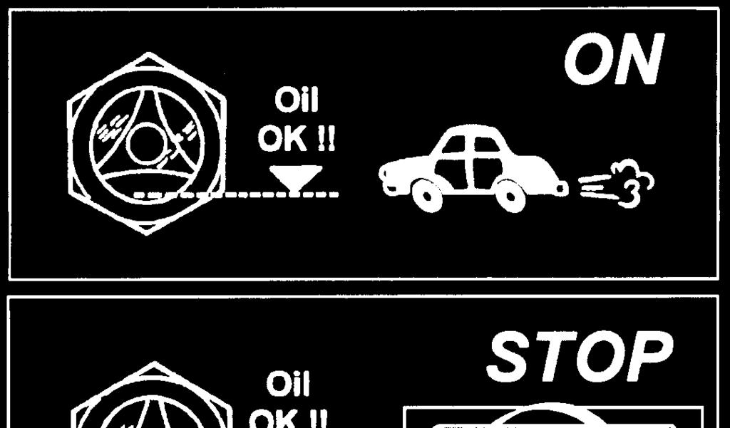
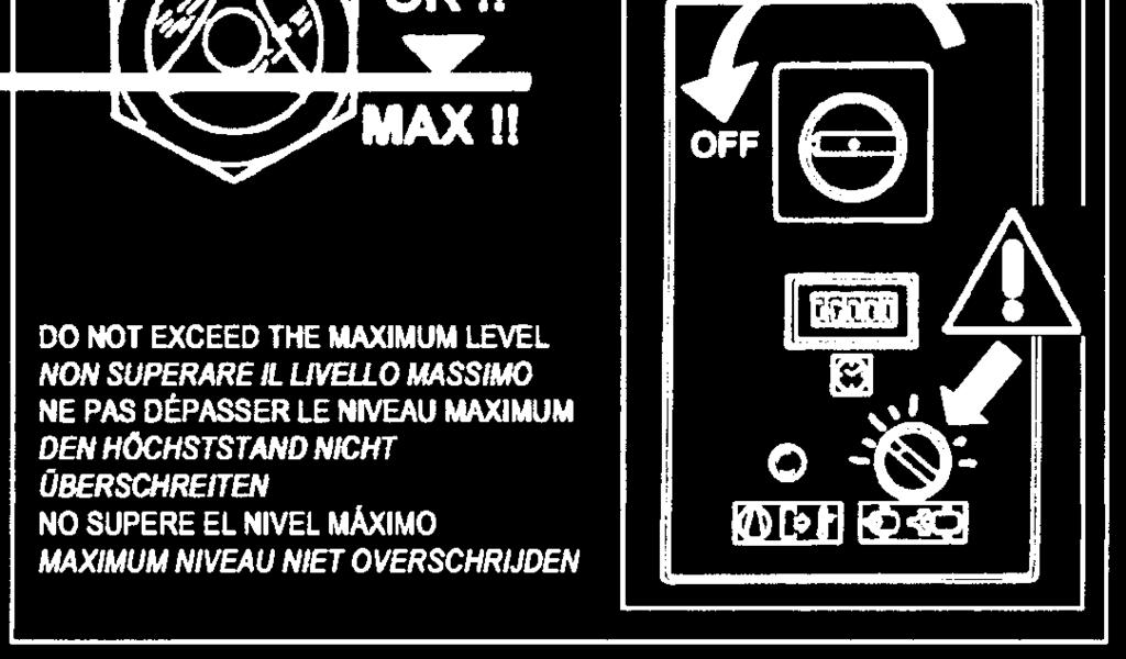
19 5. DRAINING CONDENSATE FROM THE OIL TANK If the compressor work cycle contemplates long pauses during which the machine cools down, a certain amount of condensate will gather in the oil tank. This happens, for example, when stopping overnight or at weekends. The condensate must be drained off every 50 hours or every week. This operation may be performed only when the machine is cold, that is when it has been switched off for at least 8 hours. BEFORE DRAINING THE CONDENSATE IT IS OBLIGATORY TO STOP THE MACHINE AND DISCONNECT IT FROM THE POWER MAINS. Proceed as follows: - Turn in position No load the selector Rif. Fig. 7 - Wait 0 seconds to blow OFF the pressure - Stop the machine, turning in OFF position the isolating switch Ref. Fig Press the button switch Rif. Fig. 7 (on the dryer if fitted). - Turn on the differential supply switch, Ref. 4 (on the screw-compressor) and Ref. 5 (on the dryer if fitted) Fig FIG DO NOT EXCEED THE 6 MAXIMUM LEVEL Cod Edition 05/00-9
20 - Wait for the machine to cool down. - Remove the panel Ref. 6 Fig. 7 with the key provided. - SLOWLY turn on the tap Ref. 8 Fig. 7 and let the condensate flow out. - When the first traces of oil appear, turn off the tap. CONDENSATE MUST BE DISPOSED OF IN CONFORMITY WITH THE LOCAL REGULATIONS IN FORCE. - Check the oil level on the indicator Ref. 9 Fig If the oil level is under the minimum, top up as described at point 5.. USE OIL OF THE SAME TYPE AS THAT ALREADY IN THE MACHINE; DO NOT MIX DIFFERENT TYPES OF OIL 5. CHECK OIL LEVEL AND TOP UP - Stop th e m a c hi ne, turni ng i n OFF p os iti on th e i s ol a tin g s w itc h Ref. F ig. 7, w he n the s e le c tor Re f. F ig. 7 light is ON - WAIT A 0 MINUTES FOR THE FOAM IN THE OIL COLLECTOR TO ABATE. - Check the oil level on the indicator Ref. 9 Fig If the oil level is too low, fill up as follows: to the red line. - Turn in OFF position the isolating switch Rif. Fig. 7 (on the dryer if fitted) - Turn on the differential supply switch, Ref. 4 (on the screw-compressor) and Ref. 5 (on the dryer if fitted) Fig. 7. USE OIL OF THE SAME TYPE AS THAT ALREADY IN THE MACHINE; DO NOT MIX DIFFERENT TYPES OF OIL. BEFORE CARRYING OUT ANY OPERATION ON THE MACHINE, ENSURE THAT THE ELECTRIC POWER SUPPLY HAS BEEN DISCONNECTED. - Open the front protection Ref. 6 Fig. 7 using the special key. - Remove the fixed protection device (machine cover) Ref. 7 Fig Slowly unscrew the oil cap Ref. 0 Fig 7, ensuring there is no pressure inside. - Top up to maximum level Ref. 9 Fig. 7, with oil of the same type in the compressor. - Close the oil manifold cap Ref. 0 Fig Close the fixed protection (machine cover) Ref. 7 Fig. 7 device again, using the appropriate safety screws. - Close the front protection Ref. 6 Fig CLEANING THE FILTERING PANEL - Turn in position No load the selector Rif. Fig Wait 0 seconds to blow OFF the pressure - Stop the machine, turning in OFF position the isolating switch Ref. Fig Turn on the differential supply switch Rif. 4 Fig Clean the filtering panel Rif. Fig. 7A with a jet of air wash it with water, do not use solvents. FIG. 7A EVERY 50 WORKING HOURS, CLEAN THE FILTERING PANEL. 0 - Edition 05/00 Cod
21 5.5 CLEANING THE SUCTION FILTER OR CHANGING THE FILTER - Turn in position No load the selector Rif. Fig. 8 - Wait 0 seconds to blow OFF the pressure. - Stop the machine, turning in OFF position the isolating switch Ref. Fig Turn in OFF position the isolating switch Rif. Fig. 8 (on the dryer if fitted) - Turn on the differential supply switch, Ref. 4 (on the screw-compressor) and Ref. 5 (on the dryer if fitted) Fig. 8. HOT PARTS INSIDE - Remove the fixed protection device (machine cover) Ref. 6 Fig Remove the cover Ref. 7 Fig. 8 (Check the direction of the arrow). - Remove the filter Ref. 8 Fig FIG AVOID DROPPING FOREIGN BODIES INTO THE SUCTION MANIFOLD. - Clean the filter with a jet of air, working from inside to outside, DO NOT USE WATER OR SOLVENTS. Alternatively, fit a new filter. - Clean the disk on which the filter rests with a clean cloth. - Fit the filter and the cover - If necessary, dispose of the old filter in conformity with the local regulations in force. - Close the fixed protection (machine cover) Ref. 6 Fig. 8 device again, using the appropriate safety screws.. Cod Edition 05/00 -
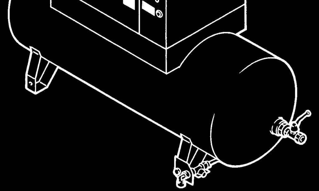
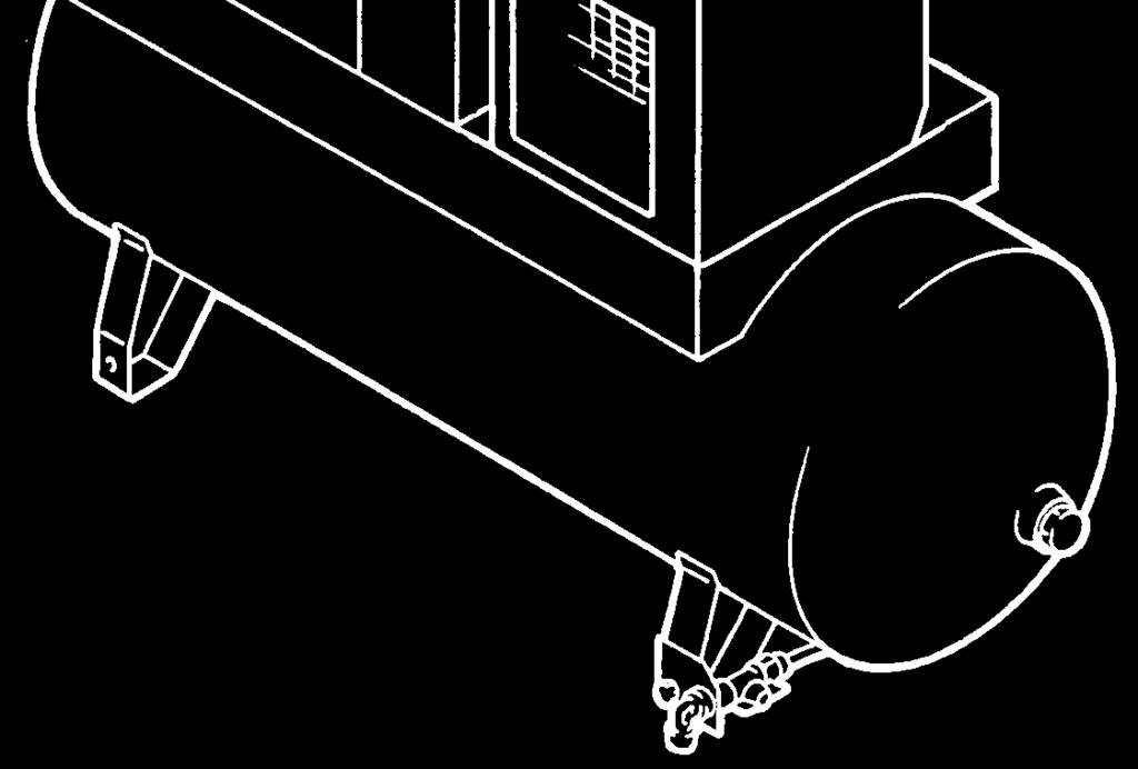
22 5.6 CHECKING THE AUTOMATIC AND MANUAL CONDENSATION EMPTYING (FOR DRYER AND TANK) BEFORE CARRYING OUT ANY MAINTENANCE, STOP THE MACHINE AND DISCONNECT IT FROM THE POWER MAINS AND FROM THE COMPRESSED AIR DISTRIBUTION NETWORK. The automatic and manual condensation drain must be checked (Rif. every 500 hours and Ref. every 4 hours ) Fig. 9. Proceed as follows: - Press the "TEST" button, Ref. Fig. 9, for a few seconds to check if the condensation is correctly emptied from the drainage pipe - Check manual drain Ref. Fig. 9) from the tank, to ensure that condensation is correctly emptied from the valve, (PURGE EVERY DAY). FIG. 9 - Edition 05/00 Cod
23 5.7 CLEANING THE CONDENSER BATTERY (FOR DRYER ) BEFORE CARRYING OUT ANY MAINTENANCE IT IS OBLIGATORY TO STOP THE MACHINE AND DISCONNECT IT FROM THE POWER MAINS AND FROM THE COMPRESSED AIR DISTRIBUTION NETWORK. The condenser must be cleaned every month (Ref. Fig. 0). Proceed as follows: - Turn in position No load the selector Rif. Fig. 0 - Wait 0 seconds to blow OFF the pressure - Stop the machine, turning in OFF position the isolating switch Ref. Fig Turn in OFF position the isolating switch Rif. 4 Fig. 0 - Turn on the differential supply switch, Ref. 5 (on the screw-compressor) and Ref. 6 (on the dryer if fitted) Fig. 0. HOT PARTS INSIDE - Remove the protection Ref. 8 Fig. 0 - Clean the condenser fins Ref. Fig. 0 with compressed air. DO NOT USE WATER OR SOLVENTS. - Close the protection Ref. 8 Fig FIG CLEAN THE DIRT COLLECTION FILTER FOR DRYER (Fig. 0) BEFORE CARRYING OUT ANY MAINTENANCE, STOP THE MACHINE AND DISCONNECT IT FROM THE POWER MAINS AND FROM THE COMPRESSED AIR DISTRIBUTION NETWORK. Proceed as follows: - Close the tap Ref. 7 Fig. 0 - Turn in position No load the selector Rif. Fig. 0 - Wait 0 seconds to blow OFF the pressure - Stop the machine, turning in OFF position the isolating switch Ref. Fig Depressurise the dryer by pressing the "TEST" condensation emptying button (for about 0-0 seconds), which is fitted on the timer, Ref. Fig. 0.. Cod Edition 05/00 -
24 - Turn in OFF position the isolating switch Rif. 4 Fig. 0 - Turn on the differential supply switch, Ref. 5 (on the screw-compressor) and Ref. 6 (on the dryer if fitted) Fig Release pressure from the machine by turning on the tap Ref. Fig Remove the stopper Ref. 0 Fig. 0 - Remove the filter Ref. 9 Fig. 0 - Clean the filter Ref. 9 Fig. 0 with a jet of air, working from inside to outside. - Install the filter, fix the plug. 6.0 PERIODS OF INACTIVITY If the machine has to remain inactive for a long period: - Close the tap Ref. and Ref. Fig.. - Depressurise the dryer by pressing the "TEST" condensation emptying button (for about 0-0 seconds), which is fitted on the timer, Ref. Fig To turn in position No load the selector Rif. 4 Fig. - Wait 0 seconds to blow OFF the pressure - Stop the machine, turning in OFF position the isolating switch Ref. 5 Fig.. - Turn in OFF position the isolating switch Rif. 6 Fig. (on the dryer if fitted) - Turn on the differential supply switch, Ref. 7 (on the screw-compressor) and Ref. 8 (on the dryer if fitted) Fig.. - Release pressure from the machine by turning on the tap Ref. Fig.. - Close the taps Rif. Fig. off again after discharging all the residual air pressure. 7 FIG During periods of inactivity the weather must be protected against atmospheric agents, dust and humidity which could damage the motor and the electrical system. To restart the machine after periods of inactivity, consult the manufacturer. 7.0 SCRAPPING THE UNIT If the machine is to be scrapped, it must be dismantled into parts of the same material, to be disposed of according to the local regulations in force. ALWAYS RESPECT THE REGULATIONS IN FORCE FOR DISPOSING OF OLD OIL AND OTHER POLLUTING MATERIALS SUCH AS SOUND-DEADENING, INSULATING FOAM, ETC. 4 - Edition 05/00 Cod
25 8.0 LIST OF SPARE PARTS FOR ROUTINE MAINTENANCE HP 0 HP 5 kw 7,5 kw Ref. DESCRIPTION Code Q.ty 6,8 bar 8,6 bar 0 bar 6,8 bar 8,6 bar 0 bar (PSI 00) (PSI 5) (PSI 45) (PSI 00) (PSI 5) (PSI 45) Suction air filter (st Serie) Oil filter Separator cartridge Filter-air assy. (st Serie) Belt Belt Belt Suction air filter (nd Serie) from 6 following serial number onwards: CAI 7460 Filter-air assy. (nd Serie) from 7 following serial number onwards: CAI 7460 FIG Cod Edition 05/00-5
26 9.0 TROUBLE-SHOOTING AND EMERGENCY REPAIRS N.B. OPERATIONS MARKED MUST BE CARRIED OUT BY PROFESSIONALLY SKILLED PERSONNEL APPROVED THE MANUFACTURER ALL WORK MUST BE CARRIED OUT BY PROFESSIONALLY SKILLED PERSONNEL. BEFORE CARRYNG OUT ANY MAINTENANCE STOP THE MACHINE AND DISCONNECT IT FROM THE POWER MAINS. 9. TROUBLE-SHOOTING AND EMERGENCY REMEDIES FOR ROTARY SCREW COMPRESSOR FAULT FOUND POSSIBLE CAUSES OBSERVATIONS ) The machine does not start A - no power B - the transformer protection fuse is broken ) The machine does not start A - the thermal protection in the main motor has triggered ) The machine does not start. A - the oil-overheating thermostat has triggered. - check the power supply line, Chapter. - replace fuse (Ref. 8 Fig. 6) - To rearm, the thermic relay Ref. OL wiring diagram - environment temperature too high; improve ventilation in the compressor room, Chapter 9. - cooling radiator is dirty, clean the radiator - oil level too low; top up the oil tank 4) The compressor does not reach working pressure 4A - the compressed air consumption is too high 4B - the discharge electrovalve remains open, Ref. SOL wiring diagram - check the electric system 5) Excess oil consumption 5A - deteriorated oil separating filter 5B - oil level is too high - change the oil separating filter, Chapter 6 - Edition 05/00 Cod
27 9. TROUBLE-SHOOTING AND EMERGENCY REPAIRS FOR THE DRYER ALL WORK MUST BE CARRIED OUT BY PROFESSIONALLY SKILLED PERSONNEL. BEFORE CARRYNG OUT ANY MAINTENANCE, STOP THE MACHINE AND DISCONNECT IT FROM THE POWER MAINS. N.B. OPERATIONS MARKED MUST BE CARRIED OUT BY PROFESSIONALLY SKILLED PERSONNEL APPROVED THE MANUFACTURER FAULT FOUND POSSIBLE CAUSES OBSERVATIONS ) No compressed air passes through the dryer outlet A) The pipes are frozen inside -The bypass valve of the hot gas is broken or out-of-calibration -The room temperature is too low and the evaporators piping are obstructed with ice ) Presence of condensate in the pipings. A) The condensate separator does not work correctly -Check the solenoid exhaust valve -Check the drainage timer B) The dryer is working outside its rating -Check the flow rate of treated air -Check the room temperature -Check the air temperature at the dryer inlet. -Clean the condenser. ) The compressor head is very hot > 55 C (> F) C) The dryer is working under bad conditions of condensation Make reference to B Make reference to C A) The cooling circuit is not working with the right gas charge 4) Motor cuts out on overload Make reference to B Make reference to C Make reference to A 5) The motor hums and does not start. The line voltage is too low. You switched the machine off and on again without leaving enough time for the pressure balancing. The starting system of the motor is defective. 6) The compressor is very noisy. Troubles with the internal mechanical parts or with the valves -Check the good operation of the fan. -Check if there are leaks of refrigerating gas. - Charge it again. -Contact the electric power company -Wait a few minutes before starting the machine again. -Check the running and starting relays and condensers (if any). Cod Edition 05/00-7
28 PART B THIS PART OF THE INSTRUCTIONS MANUAL IS RESERVED FOR CERTIFIED, FACTORY APPROVED TECHNICIANS. 0.0 STARTING UP BEFORE PERFORMING MAINTENANCE ON THE COMPRESSOR (OR DRYER), MAKE SURE THAT BOTH UNITS HAVE BEEN DISCONNECTED FROM THE MAIN ELECTRIC POWER SUPPLY BY SWITCHING OFF THE DISCONNECT SWITCH TO BOTH UNITS. 0. PREPARING FOR SETTING UP After checking everything as indicated in Chap., folow the instructions in Fig.. - Fit the sound-deadening panels Ref. - These parts are packed in the bodywork. FIG. 8 - Edition 05/00 Cod
29 0. PRELIMINARY CHECKS Check the oil level Ref. Fig. A ; when delivered the machine is filled with oil; if the oil level is not as intended, top up with the same oil as the original type. If more than months have passed between the inspection in the factory and the date of installation, lubricate the screw group before starting up, following the procedure described below: - Remove the protection Ref. Fig. A - Remove the fixed protection device (machine cover) Ref. Fig. A. - Remove the cover Ref. 4 Fig. A - Remove the air filter Ref. 5 Fig. A - Pour a little oil into the suction unit. - Reassemble the air filter Ref. 5 Fig. A - Reassemble the cover Ref. 4 Fig. A If more than 6 months have passed between the inspection in the factory and the date of installation, consul the manufacturer. 0. STARTING THE DRYER Start the dryer before turning on the compressed air. The compressed air piping will be free of condensate only by doing so. The dryer must be kept running during all the time the air compressor is running. WARNING: if the dryer is switched off, before starting it again, wait at least 5 minutes in order to allow the pressure balancing. Oil 4 FIG. A 5 DO NOT EXCEED THE MAXIMUM LEVEL.. Cod Edition 05/00-9
30 0.4 CHECK THE COMPRESSOR ROTATION DIRECTION AND START UP - Check that all the protective shields are in place. - Apply voltage to the control panel by operating the automatic differential switch of the line Ref. Fig Start the compressor by turning the switch to ON, Ref. Fig. 4 and after second, stop it by turning the switch to OFF. - If the rotation is correct, the paper sheet Ref. is blown up (See Fig. A) - If the rotation is not correct, the paper sheet remains flat (See Fig. B) PHASE INCORRECT ALL WORK ON THE ELECTRIC PLANT, HOWEVER SLIGHT, MUST BE CARRIED OUT BY PROFESSIONALLY SKILLED PERSONNEL. - Disconnect the energy supply and invert two connections as per Ref. Fig. B. IT IS ADVISABLE NOT TO DO ANYTHING ON THE MACHINE PANEL. IF ALL THE INSTRUCTIONS FOUND IN THIS MANUAL HAVE BEEN OBSERVED THE MACHINE CAN BE STARTED. FIG. 4 FIG. A FIG. B OK Protect the power cable with a suitable conduit. These cables are part of the machine 4 m/ ft. PHASE INCORRECT WARNING - TO PREVENT WRONG ROTATION DIRECTION,THIS UNIT IS EQUIPPED WITH A PHASE SEQUENCE CONTROLLER. - IF THE UNIT DOESN T START-UP, PLEASE REVERSE TWO PHASES, ACCORDING TO THE USER MANUAL INDICATION. ALL WORK ON THE ELECTRIC PLANT, HOWEVER SLIGHT, MUST BE CARRIED OUT BY PROFESSIONALLY SKILLED PERSONNEL 0 - Edition 05/00 Cod
31 .0 MAINTENANCE REQUIRES COMPLETE KNOWLEDGE AND UNDERSTANDING OF COMPRESSOR OPERATION AND MAINTENANCE BEFORE PERFORMING ANY MAINTENANCE PROCEDURES, IT IS NECESSARY TO STOP BOTH THE COMPRESSOR AND DRYER, AND DISCONNECT BOTH UNITS FROM THE MAIN POWER SUPPLY AND CLOSE THE AIR VALVE TO THE AIR SYSTEM. MAINTENANCE SCHEDULE These maintenance intervals are recommended for work environments that are not dusty and are will ventilated. For particularly dusty environments, double the frequency of controls. Every 4 working hours Drain condensate from the air tank Every 50 working hours Drain condensate from the oil tank Check the oil level Every 500 hours Clean the air suction filter Check automatic condensation emptying Clean the condenser battery (on the dryer if fitted) Clean the dirt collection filter Check belt tension Every 000 hours Every 4000 hours Change the suction filter Change the oil ( ) Change the oil filter Clean the finned surface of the air-oil cooler Change the oil separating filter It is recommended that the compressor oil be changed once per year reardless of the number of hours of operation. Oil must be changed more frequently than once per year if the compressor is operating in a dirty enviroment. N.B.: THE OPERATIONS MARKED ARE DESCRIBED IN PART "A" OF THIS MANUAL ON CHAPTER 5.. Cod Edition 05/00 -
32 .0 CHANGING THE OIL CAUTION: THIS OPERATION MUST BE DONE TOGETHER WITH THE OIL FILTER AND AIR FILTER EXCHANGE BEFORE CARRYING OUT ANY MAINTENANCE JOBS IT IS OBLIGATORY TO STOP THE MACHINE AND DISCONNECT IT FROM THE POWER MAINS AND FROM THE COMPRESSED AIR DISTRIBUTION NETWORK. Oil changing is an important operation for the compressor: If the lubrication of the bearing is not efficient, the compressor life will be short. The oil must be changed when the machine is still warm, that is immediately after stopping it. The suggestions listed below should be scrupulously followed. After draining the old oil out of the machine Ref. Fig Fill the oil manifold Ref. Fig. 5 up to the level mark - Close all the protections (cover and front protection) - Start the compressor. - After about minute, stop the machine, turning in OFF position the isolating switch Ref. Fig. 5. PROCEED AS DESCRIBED AT CHAPTER 5. FIG. 5 DO NOT EXCEED THE MAXIMUM LEVEL. THE OLD OIL MUST BE DISPOSED OF IN COMPLIANCE WITH THE LOCAL REGULATIONS IN FORCE. DO NOT MIX DIFFERENT OILS FROM DIFFERENT MANUFACTURERS AND DIFFERENT VICOSITIES (GRADES) NOTE ON LUBRICANTS When delivered the machine is filled with oil. In normal conditions of use, these lubricants have proved to be able to withstand use for as many as hours. However, due to the external polluting agents that get into the compressor with the air that it takes in, it is advisable to change the oil at more frequent intervals, as indicated on the routine maintenance chart. If the compressor is being used at high temperatures (continuous operation above 90 C 94 F) or in particularly severe conditions, we advise changing the oil at shorter intervals than those recommended in the maintenance chart. - Edition 05/00 Cod
33 .0 REPLACING THE AIR/OIL SEPARATOR FILTER AND THE OIL FILTER BEFORE PERFORMING ANY MAINTENANCE PROCEDURES, THE COMPRESSOR AND DRYER MUST BE STOPPED, ALL ELECTRICAL POWER DISCONNECTED USING THE MAIN POWER SUPPLY DISCONNECT SWITCHES AND THE AIR VALVE CLOSED OFF FROM THE COMPRESSED AIR SYSTEM. CHECK THAT THE COMPRESSOR IS NOT UNDER INTERNAL PRESSURE. Proceed as follows: - Open the front panel Ref. Fig. 6 with the special key. - Remove the fixed protection device (machine cover) Ref. Fig Remove the oil separation filter Ref. and oil filter Ref. 4 Fig. 6 - Lubricate the filter seals with a little oil before fitting. - Tightening must be done by hand. - Close the fixed protection (machine cover) Ref. Fig. 6 device again, using the appropriate safety screws. - Close the panel Ref. Fig FIG BELT TENSION BEFORE CARRYING OUT ANY MAINTENANCE THE MACHINE MUST BE STOPPED, CUT OFF THE MACHINE FROM THE ELECTRICAL MAINS AND FROM THE COMPRESSED AIR DISTRIBUTION CIRCUIT, CHECK THAT THE MACHINE IS NOT UNDER PRESSURE. Tightening or retightening new belts Proceed as follows: - Open the front panel Ref. Fig. 7 with the special key. - Remove the fixeds protections device Ref.,, 4 Fig Slacken the screws by half a turn Ref. 5 Fig. 7 - Adjust the belt tension by turning the screw Ref. 6 Fig Close the screws again Ref. 5 ( ) Fig. 7 - Tension is correct if, when a force of 5 kg. Is exercised halfway along the belt between the pulleys, there is an offset of about 6 mm. / 0, in. (see Fig. A). - Close the fixeds protections Ref.,, 4 Fig. 7 device again, using the appropriate safety screws - Close the panel Ref. Fig REPLACING THE BELT BEFORE CARRYING OUT ANY MAINTENANCE THE MACHINE MUST BE STOPPED, CUT OFF THE MACHINE FROM THE ELECTRICAL MAINS AND FROM THE COMPRESSED AIR DISTRIBUTION CIRCUIT, CHECK THAT THE MACHINE IS NOT UNDER PRESSURE. Proceed as follows: - Open the front panel Ref. Fig. 7 with the special key. - Remove the fixeds protections device Ref.,, Fig Slacken the screws by half a turn Ref. Fig. 8. Cod Edition 05/00 -
34 - Release belt tension by unscrewing the screw Ref. Fig. 8 - Unscrew screws Ref. Fig. 8, remove the fan cowl Ref. 4 - Dismantle and remove the belt Ref. 5 (Q.ty ) from the fan opening, and fit the new belt following the instructions in reverse order. - To set belt tension, proceed as given in Chap Reassemble the fan cowl Ref. 4 Fig. 8 - Reassemble the permanent protections Ref., Fig. 7 fixing them in place with the special safety screws - Close the panel Ref. Fig. 7 FIG mm (0, in) 5 5 F f 7 Fig. A ( ) Tightening torque = N. 0 FIG F = 5 kg. - ( lb.), force to be applied at the centre line, at right angles to the new belt. - f = 6 mm. (0, in.), clearance after the application of F. (after 00 h operation F = kg. - 6,6 lb.) 4 - Edition 05/00 Cod
35 6.0 ELECTROPNEUMATIC DIAGRAM STANDARD AIR CAPACITY NO DRYER STANDARD AIR CAPACITY WIHT DRYER AIR CIRCUIT OIL CIRCUIT CONTROL CIRCUIT SUCTION FILTER AIR RECEIVER SUCTION REGULATOR 4 SAFETY VALVE SCREW COMPRESSOR 5 SAFETY OIL TEMPERATURE 4 OIL DISCHARGE VALVE 6 ELECTRIC MOTOR 5 OIL MANIFOLD 7 NO-LOAD RUNNING SOLENOID VALVE 6 OIL FILTER 8 OIL LEVEL 7 THERMOSTATIC VALVE 9 CONDENSATE DISCHARGE VALVE 8 AIR-OIL COOLER 0 BLED SOLENOID VALVE 9 AIR PRESSURE SWITCH IMPURITY TRAP 0 AIR PRESSURE GAUGE CONDENSATE ELECTRONIC DRAIN VALVE MINIMUM PRESSURE VALVE AIR-OIL SEPARATOR. Cod Edition 05/00-5

 SUCTION SIDE OF REFRIGERATION COMPRESSOR Evaporating Pressure bar (psi) RATED VALUES (Temperat.")


36 7.0 DRYER CALIBRACION HOT GAS BYPASS VALVE N.B. these valves have already been calibrated and they do not require any adjistment. A dew point different fro m the rated one generally depends on causes which are not attributable to their operation. ) Protective cover ) Adiusting screw WORKING PRESSURES AND TEMPERATURES OF R4a Evaporat. Temperat. C ( F) SUCTION SIDE OF REFRIGERATION COMPRESSOR Evaporating Pressure bar (psi) RATED VALUES (Temperat. 0 C 68 F) (,8 5,6) R4A,, (0,4,) 7. FLOW DIAGRAM OF THE DRYER AIR OUTLET AIR INLET CONDENSATE DRAIN REFRIGERANT COMPRESSOR 9 HOT GAS BYPASS VALVE FREON CONDENSER 0 AIR-TO-AIR EXCANGER MOTOR FAN DEW POINT THERMOMETER 4 EVAPORATOR FAN PRESSURE SWITCH 5 DEMISTER CONDENSATE SEPARATOR CONDENSATE DISCHARGE SOLENOID VALVE 6 IMPURITY TRAP 7 EXPANSION CAPILLARY TUBE 8 REFRIGERATION FLUID FILTER 6 - Edition 05/00 Cod


.. Replace the control power fuses (FU) with the KTK- / KTK / fuses provided.")

. Adjustment Screw Overload (OL) Settings 0 HP 7,5 kw 5 HP kw 00-08V 6. 48 0V 4.")
37 8.0 VOLTAGE CONVERSION IMPORTANT: conversion. Be sure to remove electrical power to the unit before performing this voltage The standard voltage configuration for the compressor is mentioned on the data plate of the machine. To convert the operating voltage of the compressor for either 00V or 0V or 460V operation, the following simple modifications must be performed. Key Required Modifications:. Adjust the motor overload (OL) setting.. Rewire the control power transformer (T).. Replace the control power fuses (FU) with the KTK- / KTK / fuses provided. 4. Modifiy the terminal bridge configuration for the desired voltage. 5. Replace the VOLTAGE sticker with the appropriate voltage sticker provided. To adjust the motor overload (OL) setting, simply rotate the adjustment screw on the face of the overload to the required setting (see table below). Adjustment Screw Overload (OL) Settings 0 HP 7,5 kw 5 HP kw 00-08V V V To rewire the control power transformer (T), remove the wire connected to the transformer terminal ma rked 460 and move the wire to the terminal marked with the desired voltage (00V or 0V).. Cod Edition 05/00-7
38 The two fuses marked FU are easily replaced by opening the fuseholder and replacing the fuses with the KTK - fuses supplied with the compressor. Fuses (FU) Fuses (FU) To modify the terminal bridge configuration to the motor, configure the terminal bridges for the desired voltage (00V or 460V or 0V) according to the schematic below. The terminal bridges can be easily removed using a pair of pliers. Additional terminal bridges are provided with the compressor. Terminal Bridge Locate the yellow voltage stickers provided with the compressor. Replace the existing sticker with the appropriate voltage sticker (00V or 0V or 460V). Fuses KTK- / KTK ½ Voltage Stickers Terminal Bridges Voltage Stickers 8 - Edition 05/00 Cod
INSTRUCTION AND MAINTENANCE MANUAL DRYERS A5 - A6 - A7 - A7,5 - A8 - A9 - A10
 Code 00773 04 Edit. 03/0 INSTRUCTION AND MAINTENANCE MANUAL DRYERS A5 - A6 - A7 - A7,5 - A8 - A9 - A0 READ THIS MANUAL CAREFULLY BEFORE CARRYING OUT ANY OPERATIONS ON THE DRYER. Cod. 00773 04 - Edition
INSTRUCTION AND MAINTENANCE MANUAL
 Code 007758 0 Edit. 0/009 INSTRUCTION AND MAINTENANCE MANUAL DRYERS A A A A READ THIS MANUAL CAREFULLY BEFORE CARRYING OUT ANY OPERATIONS ON THE DRYER. Cod. 007758 0 - Edition 0/009 - CONTENTS PART A:
INSTRUCTION AND MAINTENANCE MANUAL DRYERS A 11 - A 12 - A 13 - A 14 (R410A)
") Code 007806 0 Edit. 0/04 INSTRUCTION AND MAINTENANCE MANUAL DRYERS A - A - A - A 4 (R40A) READ THIS MANUAL CAREFULLY BEFORE CARRYING OUT ANY OPERATIONS ON THE DRYER. Cod. 007806 0 - Edition 0/04 - CONTENTS
Code 007806 0 Edit. 0/04 INSTRUCTION AND MAINTENANCE MANUAL DRYERS A - A - A - A 4 (R40A) READ THIS MANUAL CAREFULLY BEFORE CARRYING OUT ANY OPERATIONS ON THE DRYER. Cod. 007806 0 - Edition 0/04 - CONTENTS
NON-CYCLING REFRIGERATED AIR/GAS DRYERS QPNC 75 to QPNC 250 OPERATOR S MANUAL
 NON-CYCLING REFRIGERATED AIR/GAS DRYERS QPNC 75 to QPNC 250 OPERATOR S MANUAL DATE OF PURCHASE: MODEL: SERIAL NO.: Record above information from nameplate. Retain this information for future reference.
HP / 20(IVR) KW / 15(IVR)
 KW / 15(IVR)") MANUAL USE AND MAINTENANCE SILENCED SCREW ROTARY COMPRESSOR UNITS HP - 0 / 0(IVR) KW - / (IVR) Code 00780044 0 Edition 0/0 THIS MACHINE MUST BE CONNECTED TO TWO DIFFERENT POWER SUPPLIES: THREE-PHASE SUPPLY
MANUAL USE AND MAINTENANCE SILENCED SCREW ROTARY COMPRESSOR UNITS HP - 0 / 0(IVR) KW - / (IVR) Code 00780044 0 Edition 0/0 THIS MACHINE MUST BE CONNECTED TO TWO DIFFERENT POWER SUPPLIES: THREE-PHASE SUPPLY
Instruction Manual EN CP COMPRESSOR. Model CPD CPD 75
 Instruction Manual EN CP COMPRESSOR Model CPD 75-00 62 305 8 65 CPD 75 TECHNICAL DATA STANDARD MACHINES CPD MODEL 75 00 Nominal pressure at full flow PSI 00 25 50 75 00 25 50 75 Actual flow * (as per ISO
MODULAR AUTOMATIC GRANULAR ICE FLAKER
 MODULAR AUTOMATIC GRANULAR ICE FLAKER INSTRUCTIONS AND WARNINGS 24479 rev. 03 It is strictly forbidden to reproduce this instruction manual or any part thereof. Dear Customer, Congratulations on having
AUTOMATIC GRANULAR ICE FLAKER
 AUTOMATIC GRANULAR ICE FLAKER INSTRUCTIONS AND WARNINGS 24480 rev. 01 It is strictly forbidden to reproduce this instruction manual or any part thereof. Dear Customer, Congratulations on choosing a
AUTOMATIC ICE-CUBE MAKER - INSTRUCTIONS AND WARNINGS
 AUTOMATIC ICE-CUBE MAKER - INSTRUCTIONS AND WARNINGS Dear Customer, Congratulations on having chosen a quality product which will certainly fully meet your expectations. Thank you for having purchased
Atlas Copco Refrigerant compressed air dryers
 Atlas Copco Refrigerant compressed air dryers FXe 1, FXe 2, FXe 3, FXe 4, FXe 5 Instruction book Atlas Copco Refrigerant compressed air dryers FXe 1, FXe 2, FXe 3, FXe 4, FXe 5 From following serial No.
(PD[ $LU 'U\HU 5 ( ) 5, * ( 5 $ 7 ( ' 7 < 3 ( & ( 6 6 ( ' $, 5 ' 5 < ( 5 6 ('5&) ದ ('5&) Instructions Manual
 5, * ( 5 $ 7 ( ' 7 < 3 ( & ( 6 6 ( ' $, 5 ' 5 < ( 5 6 ('5&) ದ ('5&) Instructions Manual") Instructions Manual 1. Important safety notes - Please read... 1 1.1. Transportation... 1 1.2 Positioning... 1 1.3 Installation... 1 1.4 Before operating... 1 1.5 Maintenance by an engineer... 1 1.6 Maintenance
Instructions Manual 1. Important safety notes - Please read... 1 1.1. Transportation... 1 1.2 Positioning... 1 1.3 Installation... 1 1.4 Before operating... 1 1.5 Maintenance by an engineer... 1 1.6 Maintenance
AUTOMATIC MODULAR ICE-CUBE MAKER
 AUTOMATIC MODULAR ICE-CUBE MAKER INSTRUCTIONS AND WARNINGS 24851 ed. 06-2012 It is strictly forbidden to reproduce this instruction manual or any part thereof. Dear Customer, Congratulations on having
VALUE SERIES SLIMLINE MULTIDECKS
 VALUE SERIES SLIMLINE MULTIDECKS GB OPERATING INSTRUCTIONS NO CFC - HCFC Code. 26.23.247 25-01-2008 Rev. 00 ENGLISH Thank you for having chosen one of our products. You certainly have made a good investment
Polar Air Dryer. Instructions Manual PDRCF PDRCF R E F R I G E R A T E D T Y P E C O M P R E S S E D A I R D R Y E R S
 Polar Air Dryer R E F R I G E R A T E D T Y P E C O M P R E S S E D A I R D R Y E R S PDRCF1150029 PDRCF4602000 Instructions Manual TABLE OF CONTENTS 1. Important safety notes - Please read... 1 1.1. Transportation...
AUTOMATIC MODULAR ICE FLAKER
 AUTOMATIC MODULAR ICE FLAKER INSTRUCTIONS AND WARNINGS 24479 rev. 08 It is strictly forbidden to reproduce this instruction manual or any part thereof. 1 5 3 4 Mod. N. V. W 2 2 M8 18 8 18 M8 M8 3 ~ 200
AUTOMATIC MODULAR ICE-CUBE MAKER WITH VERTICAL EVAPORATOR SYSTEM
 AUTOMATIC MODULAR ICE-CUBE MAKER WITH VERTICAL EVAPORATOR SYSTEM INSTRUCTIONS AND WARNINGS 24481 ed. 11-2007 It is strictly forbidden to reproduce this instruction manual or any part thereof. Dear
MDX. Non-Cycling Refrigerated Compressed Air Dryers with Intellidrain Condensate Drain Trap. Operation & Maintenance Manual
 MDX Non-Cycling Refrigerated Compressed Air Dryers with Intellidrain Condensate Drain Trap Operation & Maintenance Manual MODELS MDX 1500 1800 2400 3000 TABLE OF CONTENTS 1.0 GENERAL 2 1.1 How to use this
MDX. Non-Cycling Refrigerated Compressed Air Dryers with zero-loss Intellidrain Drain Trap. Operation & Maintenance Manual MDX MODELS 18 THRU 250
 MDX Non-Cycling Refrigerated Compressed Air Dryers with zero-loss Intellidrain Drain Trap Operation & Maintenance Manual MDX MODELS 18 THRU 250 TABLE OF CONTENTS HOW TO USE THIS MANUAL 2 SYMBOLS 2 WARRANTY
AUTOMATIC ICE-CUBE MAKER
 AUTOMATIC ICE-CUBE MAKER INSTRUCTIONS AND WARNINGS 24478 ed. 11-2007 It is strictly forbidden to reproduce this instruction manual or any part thereof. Dear Customer, Congratulations on having chosen
C C C-600 INSTRUCTION MANUAL ICE CUBES MACHINE. (including: exploded views, part list & diagrams) CUISIMAT
 CUISIMAT") C-250 - C-400 - C-600 INSTRUCTION MANUAL ICE CUBES MACHINE (including: exploded views, part list & diagrams) Art.no.: *706.025 / *706.040 / *706.060 1 CONTENTS PRECAUTIONS... 2 INSTALLATION... 3-4 OPERATION...
C-250 - C-400 - C-600 INSTRUCTION MANUAL ICE CUBES MACHINE (including: exploded views, part list & diagrams) Art.no.: *706.025 / *706.040 / *706.060 1 CONTENTS PRECAUTIONS... 2 INSTALLATION... 3-4 OPERATION...
MDX. Non-Cycling Refrigerated Compressed Air Dryers with zero-loss Intellidrain. Operation & Maintenance Manual MODELS MDX
 MDX Non-Cycling Refrigerated Compressed Air Dryers with zero-loss Intellidrain Operation & Maintenance Manual MODELS MDX 800 1000 1200 TABLE OF CONTENTS HOW TO USE THIS MANUAL 2 SYMBOLS 2 WARRANTY 2 1.0
INSTALLATION, COMMISSIONING AND OPERATING MANUAL
 INSTALLATION, COMMISSIONING AND OPERATING MANUAL 1 YTBV-D-CE42_0109 CONTENT Available models and capacities Supplier information Warranty Safety Emergency stops/ shutdowns About this manual Models Physical
maintenance MANUAL Rotar Cube SD Rotar Cube SD Cod.197CC5200 Ed.1-07/2009
 GB use & maintenance MANUAL Rotar Cube SD Rotar Cube SD 5-7-10 - Cod.197CC5200 Ed.1-07/2009 GENERAL INFORMATION GB GENERAL INFORMATION... SAFETY INDICATIONS... INSTALLATION... 6 TECHNICAL FEATURES...
OIL COOLER INSTRUCTION HANDBOOK
 OIL COOLER INSTRUCTION HANDBOOK INDEX 1. GENERALITY 2 1.1 OPERATING RANGE 1.2 IMPORTANT 2. INSTALLATION 3 2.1 TRANSPORTATION 2.2 INSTALLATION LOCATION 2.3 PIPING 2.4 WIRING (see the electrical diagram
HTD. High Temperature Non-Cycling Refrigerated Compressed Air Dryers. Operation & Maintenance Manual. MODELS HTD 21 thru HTD 100
 HTD High Temperature Non-Cycling Refrigerated Compressed Air Dryers Operation & Maintenance Manual MODELS HTD 21 thru HTD 100 - TABLE OF CONTENTS - 1.0 GENERAL 2 1.1 How to use this manual 1.2 Symbols
INSTALLATION AND OPERATING INSTRUCTIONS General operating instructions for sample gas conditioner Model: MAK 6
 List of contents 1.0 Uses 2.0 Technical data 2.1 Operating data 2.2 Construction and installation 2.3 Climatic load 2.4 Power supply 3.0 Function and design 3.1 General comments 3.2 Design 3.3 Performance
ENVIRONMENTAL CONTROL UNIT (ECU) PART NUMBER OPERATIONS AND MAINTENANCE MANUAL
 PART NUMBER OPERATIONS AND MAINTENANCE MANUAL") ENVIRONMENTAL CONTROL UNIT (ECU) PART NUMBER 2001829 OPERATIONS AND MAINTENANCE MANUAL Prepared by: 860 Douglas Way PO Box 530 Natural Bridge Station, VA 24579 1.0 SCOPE: This Operations and Maintenance
ENVIRONMENTAL CONTROL UNIT (ECU) PART NUMBER 2001829 OPERATIONS AND MAINTENANCE MANUAL Prepared by: 860 Douglas Way PO Box 530 Natural Bridge Station, VA 24579 1.0 SCOPE: This Operations and Maintenance
Atlas Copco Oil-injected rotary screw compressors
 Atlas Copco Oil-injected rotary screw compressors GX 2 EP, GX 3 EP, GX 4 EP, GX 5 EP, GX 7 EP Instruction book Atlas Copco Oil-injected rotary screw compressors GX 2 EP, GX 3 EP, GX 4 EP, GX 5 EP, GX
Owners Manual Refrigerated Air Dryer MHT SERIES
 Owners Manual Refrigerated Air Dryer MHT SERIES IMPORTANT: READ THIS MANUAL CAREFULLY. IT CONTAINS IN- FORMATION ABOUT SAFETY AND THE SAFETY OF OTHERS. ALSO BECOME FAMILAR WITH THE PROPER INSTALLATION
Operation regulations must be strictly obeyed.
 General This manual will help the user to operate this equipment safely and correctly. Correct operation of this air drier will reduce maintenance costs and extend the working life of all systems and parts
Instruction book for Air dryers
 Instruction book for Air dryers FD7, FD16, FD30, FD40, FD60, FD80, FD100, FD120, FD160 and FD210 From following serial numbers onwards: FD7/16: AIQ 108 800 FD30/40/60: AIQ 114 800 FD80: AIQ 105 000 FD100:
NEWGATE TECHNOLOGIES, INC.
 www W.newgatetechnologies.com NEWGATE TECHNOLOGIES, INC. Installation & Operations Manual SYNERGY Series High Inlet Temperature Refrigerated Air Dryers Models SYNERGY 025 ~ SYNERGY 125 Includes Safety
CHILLER. Operator s & Installation Manual
 CHILLER MODELS: CH1001-A Operator s & Installation Manual Release Date: August 9, 2002 Publication Number: 620914301 Revision Date: May 6, 2010 Revision: E Visit the IMI Cornelius web site at www.cornelius.com
OPERATIONS AND MAINTENANCE MANUAL FOR THE 8-TON TURF CART ENVIRONMENTAL CONTROL UNIT (ECU) PART NUMBER
 PART NUMBER") OPERATIONS AND MAINTENANCE MANUAL FOR THE 8-TON TURF CART ENVIRONMENTAL CONTROL UNIT (ECU) PART NUMBER 2001927 Prepared by: 860 Douglas Way PO Box 530 Natural Bridge Station, VA 24579 1 1.0 SCOPE: This
OPERATIONS AND MAINTENANCE MANUAL FOR THE 8-TON TURF CART ENVIRONMENTAL CONTROL UNIT (ECU) PART NUMBER 2001927 Prepared by: 860 Douglas Way PO Box 530 Natural Bridge Station, VA 24579 1 1.0 SCOPE: This
Warning: 230V / 1ph / 50Hz V / 3ph / 50Hz. Remarks: Make sure that you have enough power. (See page 15 Cable table)
") 1 2 Warning: - Do not place your hand or any other objects into the air outlet and fan. It could damage the heat pump and cause injuries; - In case of any abnormality with the heat pump, cut off the power
1 2 Warning: - Do not place your hand or any other objects into the air outlet and fan. It could damage the heat pump and cause injuries; - In case of any abnormality with the heat pump, cut off the power
OPERATION AND MAINTENANCE BOOK. Glycol Deck 250 PREAMBLE
 OPERATION AND MAINTENANCE BOOK Glycol Deck 250 Document Code: 0150GLDECEN.000 This document is the property of VINSERVICE and must not be reproduced or transferred to third parties without our authorization.
User Manual GV25 GV35 GV702. Company information: Original instructions GV12066 (1)
") User Manual Original instructions GV25 GV35 GV702 Company information: www.vipercleaning.eu info-eu@vipercleaning.com GV12066 (1) 2012-04-10 USER MANUAL ENGLISH TABLE OF CONTENTS Introduction... 4 Manual
User Manual Original instructions GV25 GV35 GV702 Company information: www.vipercleaning.eu info-eu@vipercleaning.com GV12066 (1) 2012-04-10 USER MANUAL ENGLISH TABLE OF CONTENTS Introduction... 4 Manual
Part 3 Troubleshooting
 Part Troubleshooting What is in this part? This part contains the following chapters: Chapter See page Troubleshooting 2 Error Codes: Hydro-box 7 Error Codes: Outdoor Units Error Codes: System Malfunctions
PDF Created with deskpdf PDF Writer - Trial ::
 Instruction Manual Index Introduction Uncrating and Checking for Damage Locating Your Unit Installation Fill Tank Process Connections Pre Startup Startup Sequence Trouble Shooting Chart Operating Lights
FORMULA. Rotary screw compressors. kw 5,5-7, , bar
 FORMULA Rotary screw compressors kw 5,5-7,5-11 - 15-18,5-22 - 30-37 - 45-55 bar 8-10 - 13 FORMULA Total modularity The FORMULA range in line with its name, has been designed to allow a choice of complete
GENERAL 2004 HVAC SYSTEMS. Manual HVAC System - Sorento SPECIFICATIONS. Fig. 1: Air Conditioner Specifications Courtesy of KIA MOTORS AMERICA, INC.
 Fig. 2: Blower & Evaporator Unit Specifications 2004 HVAC SYSTEMS Manual HVAC System - Sorento GENERAL SPECIFICATIONS AIR CONDITIONER Fig. 1: Air Conditioner Specifications BLOWER AND EVAPORATOR UNIT HEATER
Trouble Shooting Guide FAA, 3-phase (D3631)
") Trouble Shooting Guide FAA, 3-phase (D3631) Trouble Shooting Guide Problem Possible Cause Possible Remedy Unit does not start Unit does not cool No power to unit, breaker tripped Low voltage tripped Loose
Trouble Shooting Guide FAA, 3-phase (D3631) Trouble Shooting Guide Problem Possible Cause Possible Remedy Unit does not start Unit does not cool No power to unit, breaker tripped Low voltage tripped Loose
INSTRUCTION AND MAINTENANCE MANUAL. Refrigerant Compressed Air Dryers QED 650, QED 850, QED 1050
 INSTRUCTION AND MAINTENANCE MANUAL Refrigerant Compressed Air Dryers QED 650, QED 850, QED 1050 READ THIS MANUAL CAREFULLY BEFORE CARRYING OUT ANY OPERATIONS ON THE DRYER. QUINCY QED 650, QED 850, QED
DH-Direct Fired Poultry Farm Diesel Heater
 DH-Direct Fired Poultry Farm Diesel Heater Comparison of Diesel Heater to Gas Heater Diesel LPG Gas LPG Gas KW 43 70 120 Fuel consumption/hr 3 5.1 8.8 Heat output 37000 60000 100000 Cost of fuel/lit or
ISTRUZIONI PER L USO. Climatizzatore CT300 - CT300H
 ISTRUZIONI PER L USO Climatizzatore CT300 - CT300H Dear Sir/Madam We thank you for purchasing this Pinguino appliance and congratulate you on your wise choice. Please make the time and effort to read this
WINDOW YORK TECHNICAL GUIDE. Single package Cooling only and Heat pump. Models YO-YM R407C YO V6 G YO V7 G
 WINDOW TECHNICAL GUIDE Single package Cooling only and Heat pump Models YO-YM 09-24 R407C YM 09 V6 G YM 09 V7 G YO 12-19-24 V6 G YO 12-19-24 V7 G YORK List of Contents Page 1 - Safety...2 2 - Unit packaging...2
* * SF1 - SF2 - SF4 - SF6T - SF8T. Instruction book for Stationary Compressors. Industrial Air Division - B-2610 Wilrijk - Belgium
 Instruction book for Stationary Compressors SF1 - SF2 - SF4 - SF6T - SF8T Registration code Collection: APC SF Tab: 38 Sequence: 990 This instruction book meets the requirements for instructions specified
TTK 75 ECO OPERATING MANUAL DEHUMIDIFIER TRT-BA-TTK75ECO-TC-002-EN
 TTK 75 ECO EN OPERATING MANUAL DEHUMIDIFIER TRT-BA-TTK75ECO-TC-002-EN Table of contents Notes regarding the operating manual... 01 Information about the device... 02 Safety... 04 Transport...05 Start-up...05
Rif Cod i220-0
 15 52 50 6 13 53 51 2 9 8 3 20 19 18 5 1 7 14 10 4 17 Rif Cod 1 0010060 2 0060287 3 0060310 4 0080003 5 0080004 6 0080051 7 0080053 8 0080410 9 0080413 10 0080430 11 0080432 12 0080434 13 0080435 14 0080436
Component. Maintenance. Manual Z SERIES. Evaporator Assembly
 Component Maintenance Manual with Illustrated Parts List for Z21-701-SERIES Evaporator Assembly 1 of 16 Record of Revision REVISION ISSUE POSTED NO: DATE DATE INSERTED BY: 2 of 16 List of Effective Pages
This chapter is devided into two sections:
 This chapter is devided into two sections: Page Installation requirements........................................................................ 127 The installation process..........................................................................
Owners Manual UA75 TO UA1200 SERIES Refrigerated Air Dryer
 1 Owners Manual UA75 TO UA1200 SERIES Refrigerated Air Dryer DESCRIPTION PAGE INTRODUCTION 2 INSTALLATION 3 INSTALLATION GUIDE 4 DRYER CONTROLS 5 DRYER CONTROLS AND SAFTEY SHUTDOWNS 6 START UP 6 INITIAL
SERVICING PROCEDURE R-410A LEAK TEST EVACUATION CHARGING. Bard Manufacturing Company, Inc. Bryan, Ohio Manual Page 1 of 11
 SERVICING PROCEDURE R-410A LEAK TEST EVACUATION CHARGING Bard Manufacturing Company, Inc. Bryan, Ohio 43506 Since 1914...Moving ahead, just as planned. Manual No.: 2100-479 Supersedes: NEW File: Volume
Technical instructions
 Énergie Transfert Thermique Technical instructions A different climate Environmental control solutions Version IMPORTANT The warranty of ETT units depends on the respect of these technical instructions
AIR CONDITIONER OWNER S MANUAL. Please read this manual carefully before operating your set and retain it for future reference.
 ENGLISH OWNER S MANUAL AIR CONDITIONER Please read this manual carefully before operating your set and retain it for future reference. Ceiling Suspended Original instruction ARNU18GV1A4 ARNU24GV1A4 ARNU36GV2A4
Operating instructions
 ebm-papst Mulfingen GmbH & Co. KG Bachmühle D-74673 Mulfingen Phone +49 (0) 793-0 Fax +49 (0) 793-0 info@de.ebmpapst.com www.ebmpapst.com CONTENTS. SAFETY REGULATIONS AND NOTES. Levels of hazard warnings.
Rev. A AUGUST 2012 RNP SERIES REFRIGERATED COMPRESSED AIR DRYERS OPERATOR MANUAL RNP25 RNP35 RNP50
 3227447 Rev. A AUGUST 2012 RNP SERIES REFRIGERATED COMPRESSED AIR DRYERS OPERATOR MANUAL RNP25 RNP35 RNP50 GENERAL SAFETY INFORMATION 1. PRESSURIZED DEVICES: This equipment is a pressure containing device.
Water-cooled screw chillers. Installation, Operation and Maintenance Manual D EIMWC EN. Original Instructions
 Installation, Operation and Maintenance Manual D EIMWC00404-14EN Water-cooled screw chillers EWWD 340 C18 I-SS EWWD 360 C12 I-XS EWLD 320 C17 I-SS 50Hz Refrigerant: R-134a Original Instructions Contents
TTV 4500 / TTV 4500 HP / TTV 7000
 TTV 4500 / TTV 4500 HP / TTV 7000 EN OPERATING MANUAL AXIAL FAN TRT-BA-TTV4500-4500HP-7000-TC-003-EN Table of contents The current version of the operating manual can be found at: Notes regarding the operating
MANUAL. Dryspell INSTALLATION OPERATION MAINTENANCE. Regenerative Type Heatless Desiccant Dryer
 MANUAL INSTALLATION OPERATION MAINTENANCE Regenerative Type Heatless Desiccant Dryer Dryspell Contents 1. Introduction 2 1.1 Design 1.2 Relevant Units 1.3 Statement of Conformity 1.4 Description 1.5 Adsorbant
EBAC MODEL CD425 ( ) INDUSTRIAL DEHUMIDIFIER OWNER S MANUAL
 INDUSTRIAL DEHUMIDIFIER OWNER S MANUAL") EBAC MODEL CD425 (1018110) INDUSTRIAL DEHUMIDIFIER OWNER S MANUAL Ebac Industrial Products 704 Middle Ground Boulevard Newport News, VA 23606 Tel: 757 873 6800 Fax: 757 873 3632 Website: www.ebacusa.com
EBAC MODEL CD425 (1018110) INDUSTRIAL DEHUMIDIFIER OWNER S MANUAL Ebac Industrial Products 704 Middle Ground Boulevard Newport News, VA 23606 Tel: 757 873 6800 Fax: 757 873 3632 Website: www.ebacusa.com
SPA DE USO PRIVADO SPA FOR PRIVATE USE SPA POUR UN USAGE PRIVÉ SPA FÜR PRIVATE NUTZUNG SPA PER USO PRIVATO SPA PARA USO PRIVADO SPA VOOR PRIVE-GEBRUIK
 SPA DE USO PRIVADO SPA FOR PRIVATE USE SPA POUR UN USAGE PRIVÉ SPA FÜR PRIVATE NUTZUNG SPA PER USO PRIVATO SPA PARA USO PRIVADO SPA VOOR PRIVE-GEBRUIK MANUAL DE INSTALACIÓN INSTALLATION MANUAL MANUEL D
- 1 - Updated on 18 March, 2010
 - 1 - Updated on 18 March, 2010 TABLE OF CONTENTS 1. SPECIFICATION & PARTS IDENTIFICATION...3 2. OPERATION & FUNCTION OF PARTS...4, 5 A. Cooling Operation B. Heating Operation C. Function of Parts 3. LOCATION
DRYMAX DRYMAX DRYMAX DRYMAX
 DRYMAX DRYMAX 897-8485 DRYMAX DRYMAX 905 RECEIVING AND INSPECTION 1. The dryer cannot be tilted on its side or upside down during shipping. 2. Use forklift from the bottom of the dryer when installing
Mobile Air Conditioner Instruction Manual Model TC-N9KM
 Mobile Air Conditioner Instruction Manual Model TC-N9KM Please read and retain these instructions for future reference SPECIFICATION Model no. Cooling capacity Power/Ampere consumption for cooling* Air
OK, OKA, OKAF; ELD; ELDM; ELH; OKC; SC; SCA; SCAF; OK-LN; OKA-LN; OKAF-LN.
 INSTALLATION, OPERATION & SERVICE MANUAL FOR COOLER TYPES OK, OKA, OKAF; ELD; ELDM; ELH; OKC; SC; SCA; SCAF; OK-LN; OKA-LN; OKAF-LN. 1. Introduction This manual is a guide for the installation, maintenance
Instruction Manual. Refrigerated Air Dryer
 January 2008 Edition Carefully read this manual before attempting to operate or perform maintenance on this equipment. Instruction Manual Of Refrigerated Air Dryer Hangzhou Kelin Aier Qiyuan Equipment
WARNINGS FOR THE USER: Connect BASE conforms to: Low Voltage Directive 73/23/EEC. Electromagnetic Compatibility Directive 89/336/EEC
 Connect BASE conforms to: Low Voltage Directive 73/23/EEC Electromagnetic Compatibility Directive 89/336/EEC Warnings and safety considerations Page 13 Description of the equipment 14 Technical data 14
 Dear Customer, Congratulations on having chosen a top-quality product, which is sure to live up to your expectations. Thank you for having purchased one of our products. Please read this instruction manual
TECHNICAL NOTICE GH/GHO/GAE V
 TECHNICAL NOTICE GH/GHO/GAE V1.0-02.14 INDUSTRIAL COOLING UNITS Identification Marksa SA Industrial cooling 39, avenue du Technicum CH-2400 Le Locle Version Date Modifications 1.0 14.02.14 First edition
AUTOMATIC MODULAR SCALE ICE MAKER
 AUTOMATIC MODULAR SCALE ICE MAKER INSTRUCTIONS AND WARNINGS 24850 ed. 06-2012 It is strictly forbidden to reproduce this manual or any part thereof. Dear Customer, Congratulations on having chosen
Drying Ovens Models F3 - F6 - F9
 Instruction and Maintenance Manual Drying Ovens Models F3 - F6 - F9 SUMMARY 1. GENERAL INFORMATION.....3 2. SPECIFICATIONS...4 2.1. General Specifications...4 2.2. Oven general description...4 2.3. Thermal
CHILLER. Modelli CWS BASIC CWS AQUACONTROL INSTALLATION MANUAL USAGE AND SCHEMATICS
 CHILLER CWS AQUACONTROL Modelli CWS BASIC 121 161 201 251 301 INSTALLATION MANUAL USAGE AND SCHEMATICS A041252 16/10/2012 COMPANY WITH QUALITY SYSTEM CERTIFIED BY DNV =ISO 9001/2000 9001/2008 = ISO VECO
RHGN-H: COMMERCIAL AIR HANDLER WITH VARIABLE FREQUENCY DRIVE (VFD) NOMINAL 10 TONS R-410A REFRIGERANT 2-STAGE AIR-FLOW
 NOMINAL 10 TONS R-410A REFRIGERANT 2-STAGE AIR-FLOW") INSTALLATION INSTRUCTIONS RHGN-H: COMMERCIAL AIR HANDLER WITH VARIABLE FREQUENCY DRIVE (VFD) NOMINAL 10 TONS R-410A REFRIGERANT 2-STAGE AIR-FLOW 92-106595-01-00 TABLE OF CONTENTS Introduction.......................................
INSTALLATION INSTRUCTIONS RHGN-H: COMMERCIAL AIR HANDLER WITH VARIABLE FREQUENCY DRIVE (VFD) NOMINAL 10 TONS R-410A REFRIGERANT 2-STAGE AIR-FLOW 92-106595-01-00 TABLE OF CONTENTS Introduction.......................................
USE AND INSTALLATION HANDBOOK
 Date : 10/02/14 Rev. 01 PR.T : FG006176 USE AND INSTALLATION HANDBOOK SIMPLEX-UP CONTROL PANEL FOR 1 ELECTRIC PUMP WITH CURRENT CONTROL. SIMPLEX-UP Via Enrico Fermi, 8-35020 Polverara PD Tel.049/9772407
INSTRUCTIONS FOR USE. To make the most of your new oven, read the user's instructions carefully and keep them on hand for consultation in the future.
 INSTRUCTIONS FOR USE INSTALLATION...4 SAFEGUARDING THE ENVIRONMENT... 7 IMPORTANT NOTES... 7 BEFORE USING THE OVEN... 8 OVEN ACCESSORIES... 9 CARE AND MAINTENANCE... 10 TROUBLESHOOTING GUIDE... 12 AFTER
Read this manual through carefully before installing/using the cleaner, paying special attention to the SAFETY INSTRUCTIONS
 PW1370TD 2 EN Read this manual through carefully before installing/using the cleaner, paying special attention to the SAFETY INSTRUCTIONS 3 E3 E1 C3 A1-A2-A3-A4 B4 B1 B5 B2 C1 B3 D 1 4 1 2 3 4 5 6 7 Ø13
WILKERSON MODELS DE3, DE4 AND DE5 COMPACT HEATLESS AIR DRYERS
 INSTRUCTION MANUAL FOR WILKERSON MODELS DE3, DE4 AND DE5 COMPACT HEATLESS AIR DRYERS DE3 - DE5 OPERATIONS GENERAL This instruction manual covers the installation, operation, maintenance and troubleshooting
CRU-S Series Stainless Steel Condensate Recovery Unit
 IM-UK-CRU-S UK Issue 1 CRU-S Series Stainless Steel Condensate Recovery Unit 1. Safety information 2. General product information 3. Installation 4. Commissioning 5. Storage, shutdown and equipment protection
TTV 1500 / TTV 3000 OPERATING MANUAL CONVEYING FAN TRT-BA-TTV TC EN
 TTV 1500 / TTV 3000 EN OPERATING MANUAL CONVEYING FAN TRT-BA-TTV1500-3000-TC2016-26-004-EN Table of contents Notes regarding the operating manual... 2 You can download the current version of the operating
TFV 900 OPERATING MANUAL RADIAL FAN TRT-BA-TFV900-TC-001-EN
 TFV 900 EN OPERATING MANUAL RADIAL FAN TRT-BA-TFV900-TC-001-EN Table of contents Notes regarding the operating manual... 1 Safety... 2 Information about the device... 3 Transport and storage... 4 Start-up...
Trouble Shooting Guide RAA, 1-phase (D3627)
") Trouble Shooting Guide RAA, 1-phase (D3627) Trouble Shooting Guide Problem Possible Cause Possible Remedy Unit does not start Unit does not cool No power to unit, breaker tripped Low voltage tripped Loose
Trouble Shooting Guide RAA, 1-phase (D3627) Trouble Shooting Guide Problem Possible Cause Possible Remedy Unit does not start Unit does not cool No power to unit, breaker tripped Low voltage tripped Loose
13-1. Temperature Regulator
 -1 Step 0 Type/Structure/Features Please refer to this for type, structure and features of. Step 1 Selection Please look at the ID chart to choose the right products depending on the intended uses. Details
Rotary screw compressors
 FORMULA Rotary screw compressors kw 5,5-7,5-11 - 15-18,5-22 bar 8-10 - 13-15 FORMULA Total modularity The FORMULA range in line with its name, has been designed to allow a choice of complete configurations,
User Manual for ICB Meat Grinders Models HM-12, HM-22B
 User Manual for ICB Meat Grinders Models HM-12, HM-22B INTRODUCTION This manual provides information about the appliance and the manufacturing standards applied, as well as all instructions for use and
3 In 1 AIR CONDITIONER with REMOTE CONTROL MODEL NO: CA9000 PART No: OPERATION & MAINTENANCE INSTRUCTIONS
 3 In 1 AIR CONDITIONER with REMOTE CONTROL MODEL NO: CA9000 PART No: 32305600 OPERATION & MAINTENANCE INSTRUCTIONS 0304 Parts List Item Part No Description Qty 1 FT900001 Top Cover 1 2 FT900002 Filter
Trouble Shooting Guide PAA, 1-phase (D3731)
") Trouble Shooting Guide PAA, 1-phase (D3731) Trouble Shooting Guide Problem Possible Cause Possible Remedy Unit does not start Unit does not cool No power to unit, breaker tripped Low voltage tripped Loose
Trouble Shooting Guide PAA, 1-phase (D3731) Trouble Shooting Guide Problem Possible Cause Possible Remedy Unit does not start Unit does not cool No power to unit, breaker tripped Low voltage tripped Loose
EBAC MODEL CD30 INDUSTRIAL DEHUMIDIFIER OWNER S MANUAL
 EBAC MODEL CD30 INDUSTRIAL DEHUMIDIFIER OWNER S MANUAL Ebac Industrial Products 704 Middle Ground Boulevard Newport News, VA 23606 Tel: 757 873 6800 Fax: 757 873 3632 Website: www.ebacusa.com UNPACKING
Swedish design and manufacture since 1967
 Swedish design and manufacture since 167 PVP MA20-14 rev.2 Manual User manual Copyright 2017 Pahlén AB, Box 728, SE-14 27 Upplands Väsby, Sweden Tel. +46 8 54 110 50, Fax +46 8 50 868 80, e-mail: info@pahlen.se,
ROTARY SCREW COMPRESSOR CSA 5,5-7, HP
 ROTARY SCREW COMPRESSOR CSA 5,5-7,5-10 - 15-20 HP Technology and Performance High performance, silent running, simple installation and maintenance, makes the CSA compressor belong to the top class models
CONTENTS. 1. Safety recommendations 2 Table of warning and attention plates 3. Description of the unit 4. Operation 5. Handling
 CONTENTS 1. Safety recommendations 2 Table of warning and attention plates 3. Description of the unit 4. Operation 5. Handling 6. Installation 6.1 Plates 6.2 Dimensions 6.3 Location 6.4 Free room 6.5 Installation
51AKS I S O OWNER S MANUAL
 LLOYD'S REGISTER QUALITY ASSURANCE 51AKS I S O 9 00 1 OWNER S MANUAL This manual applies to the following models Stand-alone Split 51AKS 085--- 51AKS 010--- 51AKS 185--- 51AKS 013--- 51AKS 113--- 51AKS
Refrigerant Recovery Machine. Model No Operating Manual
 Refrigerant Recovery Machine Model No. 25700 Operating Manual Safety Precautions WARNING : TO PREVENT PERSONAL INJURY AND / OR EQUIPMENT DAMAGE, CAUTION - Risk of injury. This equipment should only be
Drying Ovens for Fluxes Models F100 F200 - F400
 Instruction and Maintenance Manual Drying Ovens for Fluxes Models F100 F200 - F400 SUMMARY 1. GENERAL INFORMATION....2 2. SPECIFICATIONS.....3 2.1. General Specifications...3 2.2. Oven general description...3
Operation Manual 322 KL
 Operation Manual 322 KL 8/07 von Oertzen GmbH Ferdinand-Harten-Str. 10 22949 Ammersbek Tel. +49 40 604110 Fax +49 40 6041149 www.oertzen-gmbh.de info@oertzen-gmbh.de Table of Content 1. Introduction Page
Trouble Shooting Guide PWA, 3-phase (D10571)
") Trouble Shooting Guide PWA, 3-phase (D10571) Trouble Shooting Guide Problem Possible Cause Possible Remedy Unit does not start Unit does not cool No power to unit, breaker tripped Low voltage Loose wire
Trouble Shooting Guide PWA, 3-phase (D10571) Trouble Shooting Guide Problem Possible Cause Possible Remedy Unit does not start Unit does not cool No power to unit, breaker tripped Low voltage Loose wire
5KW ELECTRIC FAN HEATER
 5KW ELECTRIC FAN HEATER MODEL NO: DEVIL 7005 PART NO: 6935452 OPERATION & MAINTENANCE INSTRUCTIONS LS0615 INTRODUCTION Thank you for purchasing this CLARKE product. Before attempting to use this product,
UL U TR LTRASONIC S ONIC SCALE ALER PIEZO MINI
 ULTRASONIC SCALER PIEZO MINI CONTENTS XI - SYMBOLS 1. INTRODUCTION 1 Alternating current Type BF device 2. WARNINGS 1 3. PRESENTATION 1 3.1 Presentation 1 3.2 Technical description 2! Warning, please refer
INVERTER SPLIT - TYPE
 INVERTER SPLIT - TYPE ISSUE No 2 DATE 04/09/08 P/No 2020323A2868 CONTENTS SAFETY PRECAUTIONS Warning 2 Operating temperature 2 BEFORE INSTALLATION Tools needed for installation 3 Items required for installing
INSTRUCTION BOOK OIL-FREE SCROLL COMPRESSORS SF 8+, SF 11+
 INSTRUCTION BOOK OIL-FREE SCROLL COMPRESSORS SF 8+, SF 11+ Atlas Copco Oil-free scroll compressors SF 8+, SF 11+ From following serial No. onwards: API 770 000 Instruction book Original instructions COPYRIGHT