DISCOVERY DRYER TRAINING MANUAL
|
|
|
- Ralph Morrison
- 5 years ago
- Views:
Transcription

1 DISCOVERY DRYER TRAINING MANUAL CAUTION! READ THIS MANUAL CAREFULLY BEFORE DIAGNOSING OR SERVICING THIS PRODUCT.
2 Customer Service (and Part Sales) (800) Technical Support (and Part Sales) (800) USA Website us.lgservice.com Customer Service Website us.lgservice.com B2B Service Website biz.lgservice.com LG CS Academy lgcsacademy.com Published April 2006 by LG Technical Support and Training
3 IMPORTANT SAFETY NOTICE The information in this training manual is intended for use by persons possessing an adequate background in electrical equipment, electronic devices, and mechanical systems. In any attempt to repair a major appliance, personal injury and property damage can result. The manufacturer or seller maintains no liability for the interpretation of this information, nor can it assume any liability in conjunction with its use. When servicing this product, under no circumstances should the original design be modified or altered without permission from LG Electronics. Unauthorized modifications will not only void the warranty, but may lead to property damage or user injury. If wires, screws, clips, straps, nuts, or washers used to complete a ground path are removed for service, they must be returned to their original positions and properly fastened. CAUTION To avoid personal injury, disconnect the power before servicing this product. If electrical power is required for diagnosis or test purposes, disconnect the power immediately after performing the necessary checks. Also be aware that many household appliances present a weight hazard. At least two people should be involved in the installation or servicing of such devices. Failure to consider the weight of an appliance could result in physical injury. ESD NOTICE Some of the electronic components in appliances are electrostatic discharge (ESD) sensitive. ESD can weaken or damage the electronics in these appliances in a manner that renders them inoperative or reduces the time until their next failure. Connect an ESD wrist strap to a ground connection point or unpainted metal in the appliance. Alternatively, you can touch your finger repeatedly to a ground connection point or unpainted metal in the appliance. Before removing a replacement part from its package, touch the anti-static bag to a ground connection point or unpainted metal in the appliance. Handle the electronic control assembly by its edges only. When repackaging a failed electronic control assembly in an anti-static bag, observe these same precautions. REGULATORY INFORMATION This equipment has been tested and found to comply with the limits for a Class B digital device, pursuant to Part 15 if the FCC Rules. These limits are designed to provide reasonable protection against harmful interference when the equipment is operated in a residential installation. This equipment generates, uses, and can radiate radio frequency energy, and, if not installed and used in accordance with the instruction manual, may cause harmful interference to radio communications. However, there is no guarantee that interference will not occur in a particular installation. If this equipment does cause harmful interference to radio or television reception, which can be determined by turning the equipment off and on, the user is encouraged to try to correct the interference by one or more of the following measures: Reorient or relocate the receiving antenna; Increase the separation between the equipment and the receiver; Connect the equipment to an outlet on a different circuit than that to which the receiver is connected; or consult the dealer or an experienced radio/tv technician for help. COMPLIANCE The responsible party for this device s compliance is LG Electronics Alabama, Inc.; 201 James Record Road, Huntsville, AL, DLE7177WM/DLG7188WM Page 3 of 60 TRAINING MANUAL
4 Contents Regulatory Notices 3 Contents 4 Introduction 6 Sensor Dry 7 Manual Dry 7 Gas Safety Page 8 Specifications 9 Accessories 10 Installation (of accessories) 10 Rack 10 Stacking Kit 11 Pedestal 13 Modem and Monitor 15 Electric Dryer 16 Pigtail 16 4-wire Connection 16 3-wire Connection 17 Gas Dryer 19 Piping 19 Dryer Cycle Chart 20 Component Test Procedures 21 Motor Diagram and Schematic 22 Safety Switches 25 Control and PCB Layout 26 Wiring Diagram 28 Diagnostic Test 29 Test V AC Electrical Supply 30 Test 2 Thermistor Test (Power Off) 33 Test 3 Motor Test 34 Test 4 Moisture Sensor Test 35 Test 5 Door Switch Test 36 Test 6 Heater Switch Test (Electric Dryer) 37 Test 7 Gas Valve Test (Gas Dryer) 38 Test 8 Semiconductor Test 39 Gas Conversion (Natural to Propane) 40 Safety Warning 40 Orifice 41 Gas Valve Operation 42 Flow Chart 42 Ignition Sequence 42 continued on next page DLE7177WM/DLE7188WM Page 4 of 60 TRAINING MANUAL
5 Contents, continued Disassembly/Repair 43 Top Cover 43 Control Panel 44 Front Cover and Door 45 Door Reversal 45 Tub Front 46 Drum Assembly and Belt 46 Lamp 47 Vent Replacement (Rear to side exhaust) 48 Filter Assembly and Moisture Sensor 49 Back Cover 49 Air Duct 50 Rollers 51 Blower and Housing 52 Exploded Views 53 Top Cover and Control Panel 53 Cabinet and Door 54 Drum and Motor (Electric Dryer) 55 Drum and Motor (Gas Dryer) 56 Parts List 57 DLE7177WM/DLE7188WM Page 5 of 60 TRAINING MANUAL


6 INTRODUCTION The DISCOVERY dryer is very similar to other LG dryers with the exception of the LCD display on the control panel. The LCD display shows all the information formerly indicated by LEDs but also allows for scrolling instruction. When a cycle is selected, the options are preset. They can be overridden by changing them using the option buttons. Pressing the buttons cycles through the available options. If an option is not available for a particular cycle, it is grayed out or not available for selection. For example, the EXTRA HOT wash is not available for the DELICATE cycle. The interior components remain the same: motor, belt, drum, and heat source (gas or electric). The gas model can be refitted with an orifice to allow the use of propane instead of natural gas. All such conversions and adjustments should be performed by a licensed and certified gasfitter. The DISCOVERY model also has an additional sensor in the exhaust stream to detect the moisture level more accurately for better drying results. DLE7177WM/DLE7188WM Page 6 of 60 TRAINING MANUAL
 will carry a different part number depending upon the type of display.")

7 Models DLE7177WM and DLG7188WM use the LED indicator panel instead of the newer LCD. The only difference is the type of display. The dryers function identically. The main and display PCB (Printed Circuit Board) will carry a different part number depending upon the type of display. Always order parts by model number and serial number to ensure receiving the correct parts. The drying cycle is shown in the left window and the time remaining is show in the right. Feature selections like DRY LEVEL and BEEPER volume are indicated by LEDs on the panel. The DISCOVERY line of dryers feature enhanced sensor drying. In addition to the drying sensor in the tub near the filter, there is an additional sensor in the exhaust stream to ensure the correct level of dryness is determined, from damp dry to very dry. The dryer can also be set manually to dry at a particular heat level and for a specified time. DLE7177WM/DLE7188WM Page 7 of 60 TRAINING MANUAL
8 SAFETY Check the local laws and regulations concerning the installation and connection of gas. In most localities, it is illegal to connect gas piping, re-jet or adjust burners, or repair gas-fired equipment unless you are licensed and certified so to do. It is the servicer s responsibility to comply with all such regulation. DLE7177WM/DLE7188WM Page 8 of 60 TRAINING MANUAL
9 SPECIFICATIONS DLE7177WM/DLE7188WM Page 9 of 60 TRAINING MANUAL
 The STACKING KIT is used to stack a dryer on top of a matching washer. (NEVER put a washer on top of a dryer!")
10 ACCESSORIES DRYING RACK STACKING KIT PEDESTAL The DRYING RACK is used to dry items that should not be tumbled, like sweaters, tennis shoes, etc. It should be removed and stored when not in use. The rack is included with the dryer. (See installation procedure, page xx.) The STACKING KIT is used to stack a dryer on top of a matching washer. (NEVER put a washer on top of a dryer!) The stacking kit should not be used in situation where there is the possibility of excessive vibration and movement of the washer, such as in a mobile home or an upper floor of a frame structure. The stacking kit is available as an optional purchase. (See installation procedure, page 11.) The PEDESTAL can be used under either the washer or the dryer. It is possible to stack a washer and dryer on a pedestal, but the dryer controls may be difficult to reach and the possibility of vibration and movement is greater. The pedestal is available as an optional purchase. (See installation procedure, page 13.) Pedestals are available in heights of 7¼ and 13. INSTALLATION (RACK) It s simple! Open the dryer door. Put the rack in place. Select RACK DRY (2 nd button on right) Press START. Be sure the front of the rack is properly situated in the notches on either side of the filter. The back should rest on the drum and allow the drum to rotate. DLE7177WM/DLE7188WM Page 10 of 60 TRAINING MANUAL

11 INSTALLATION (Stacking Kit) WARNING! Do not attempt this alone! At least two people are required to lift the dryer and place it properly on top of the washer. Failure to observe this warning could result in serious physical injury and damage to the appliances. 1. Place the washer on a solid, even floor. If you plan to use a pedestal, install it now before going any further. 2. Peel the protective paper from the adhesive tape on the side bracket. 3. Fit the side bracket firmly to the top plate using the adhesive tape, as shown in the drawing. 4. Secure the bracket to the top plate using a screw, as shown. Repeat steps 2, 3, and 4 for the other side. 5. Level the dryer on a firm solid floor and lock down the adjusters before placing it on top of the washer. (See page xx.) Lift the dryer on top of the washer it toward the front of the washer, as shown. Slide the dryer all the way back to the stop on the rail. DLE7177WM/DLE7188WM Page 11 of 60 TRAINING MANUAL
12 INSTALLATION (Stacking Kit) continued 6. Install the front rail of the stacking kit. Push the front rail back against the stops on the side brackets. 7. Insert a screw to attach the front rail to the side bracket. Repeat step 7 for the other side. DLE7177WM/DLE7188WM Page 12 of 60 TRAINING MANUAL


13 INSTALLATION (Pedestal) For 27 Pedestals (Washer, Dryer, and Combo) 1. Remove the pedestal, installation hardware, and instructions from the shipping container. 2. Level the pedestal on a solid, flat, level floor. Lock down the rear adjusters, but leave the front ones free for now. Set the dryer on the pedestal and level it. Level it and lock down all four adjusters on the dryer. REAR FRONT Note which holes are for the washer and which are for the dryer. If you are stacking the appliances, the washer should be on the bottom. 3. Remove the protective paper from the adhesive surface of the bracket. Be particularly careful, because when this adhesive makes contact, there is no adjustment possible. NOTE: Some kits include two sets of brackets (curved for the dryer and flat (shown) for the washer.) Use the correct bracket for your application. (See next page.) DLE7177WM/DLE7188WM Page 13 of 60 TRAINING MANUAL

14 INSTALLATION (Pedestal) continued 4. Holding the adhesive part of the bracket away from the dryer, insert the screws and get them started. Press the bracket onto the dryer and tighten the screws. 5. Press the brackets onto the sides of the dryer and rub the brackets from side to side to ensure the total adhesive area is attached completely. 6. Tighten all the screws securely. 7. Lower each leg of the dryer onefourth turn with the adjusting wrench to put a little pressure between the dryer and pedestal to prevent any motion and rattling. 8. Push the dryer into place. 9. Check the level and adjust the front legs of the pedestal as necessary. Then lock down the adjusters. The pedestal kit includes the mounting plates (with adhesive covered by paper) and the screws to attach the plates. Remember, some pedestal kits come with two sets of brackets. The flat tops are for washers; the curved tops (shown) are for dryers. Use the correct brackets for your application. DLE7177WM/DLE7188WM Page 14 of 60 TRAINING MANUAL


15 INSTALLATION (Modem and Monitor) REMOTE MONITOR The monitor plugs in to any 110 Volt outlet in the home. It receives its data signal via the power lines. 1. Be sure the dryer is unplugged. Remove the modem cover. Save the cover for future use; in the event you must remove the modem, you can replace the cover. 2. Attach the modem to the socket with the screws provided. 3. Plug the monitor s power cord in an outlet where you can observe it easily. Use the stand or the wall mount bracket. 4. Press and hold the button until the display shows SET. DLE7177WM/DLE7188WM Page 15 of 60 TRAINING MANUAL


16 ELECTRICAL CONNECTION (Electric Dryer Only) PIGTAIL INSTALLATION Install the appropriate power cord for the outlet available. Grounding through the neutral conductor is prohibited in new branch-circuits, mobile homes, recreational vehicles, and where prohibited by local code. 4-wire Connection The 4-wire receptacle looks like this. Power cord with spade terminals. Power cord with ring terminals. Install a strain relief on the power cord. Then connect the terminals to the terminal block, matching the wire colors. A. Ground screw on chassis B. Green wire from power cord C. Strain relief D. Neutral screw on terminal block E. Terminal block F. Neutral wire from power cord DLE7177WM/DLE7188WM Page 16 of 60 TRAINING MANUAL
17 ELECTRICAL CONNECTION (Electric Dryer Only) continued 3-wire Connection The 3-wire receptacle looks like this. Power cord with spade terminals. Power cord with ring terminals. Install a strain relief on the power cord. Then connect the terminals to the terminal block, matching the wire colors. Add a wire to connect the chassis ground to neutral. A. Ground screw on chassis B. Green wire from power cord C. Strain relief D. Neutral screw on terminal block E. Ground-to-neutral connection F. Neutral wire from power cord DLE7177WM/DLE7188WM Page 17 of 60 TRAINING MANUAL


18 ELECTRICAL CONNECTION (Electric Dryer Only) continued Be sure to tighten all screws firmly, but do not strip them or distort the contact area. Be sure to install a strain relief on the power cord. Replace the terminal block cover by inserting the tabs into the slots and letting them slide down to engage. Fold it over to the back of the dryer so it covers the access to the terminal block. Be sure no wires are exposed or could touch any metal surface. Secure the cover with a screw. DLE7177WM/DLE7188WM Page 18 of 60 TRAINING MANUAL

19 GAS CONNECTION (Gas Dryer Only) CAUTION! (This warning applies to both natural gas and propane.) Gas is both flammable and explosive. Use caution when working with gas. In most locations, installing and connecting gas is restricted to properly trained and licensed persons. Always inspect joints and connections for a leak with a soapy solution. If you see bubbles, turn the gas off and open a window. If you smell gas, turn off the main valve and open a window. The gas dryer requires a 110 Volt, single-outlet, dedicated circuit. The cord is installed at the factory and no user-intervention is required. DLE7177WM/DLE7188WM Page 19 of 60 TRAINING MANUAL
20 DRYER CYCLE CHART * SENSOR DRY The dryness level is set by the customer. ** MANUAL DRY The temperature is set by the customer. The default settings can be overridden by the customer. DLE7177WM/DLE7188WM Page 20 of 60 TRAINING MANUAL
21 COMPONENT TESTING PROCEDURES Testing the various components of the dryer is relatively simple. Most can be checked without major disassembly. DLE7177WM/DLE7188WM Page 21 of 60 TRAINING MANUAL
22 COMPONENT TESTING PROCEDURES continued DLE7177WM/DLE7188WM Page 22 of 60 TRAINING MANUAL
23 COMPONENT TESTING PROCEDURES continued DLE7177WM/DLE7188WM Page 23 of 60 TRAINING MANUAL
24 MOTOR DIAGRAM and SCHEMATIC To check the motor, turn the power off and allow the capacitor to discharge. The centrifugal switch serves as a safety device to turn off the fuel (gas or electricity) to the heater if the motor fails to rotate. DLE7177WM/DLE7188WM Page 24 of 60 TRAINING MANUAL

. If the motor stops, the weight slides forward and turns the power off.")

25 SAFETY SWITCHES The centrifugal switch slides back and forth on the motor s shaft to operate the contacts as shown in the previous diagram. This switch provides safety in the event the motor fails. When the motor is running, centrifugal force causes the weight (black wing in photo) to slide back toward the motor windings. This motion allows electricity to operate the heater (electric element or gas valve). If the motor stops, the weight slides forward and turns the power off. RUN POSITION STOP POSITION There is an additional safety in the form of a belt switch that shuts off power to the electric motor if the belt breaks. Belt tension holds the switch closed. If the belt breaks, the switch opens and power to the motor is cut. When the motor stops, the centrifugal switch functions as a safety device to turn off the fuel (gas or electricity). The centrifugal switch includes a multipin connector (shown). The belt switch is simple. If the belt breaks, the spring pulls the lever down and it presses the switch. DLE7177WM/DLE7188WM Page 25 of 60 TRAINING MANUAL


26 DISPLAY PWB The display board is actually two boards connected by a ribbon cable. One board holds the selector knob and cycle indicator LEDs. The other holds the LCD display and adjustment buttons to override the pre-set cycle selections. The DLE7177WM board is shown below. Other models vary slightly. The gas and electric models have a different display board. DLE7177WM/DLE7188WM Page 26 of 60 TRAINING MANUAL


27 MAIN PWB The main board includes the relays that operate electric heaters and gas valves. The DLE7177WM board is shown below. Other models vary slightly. The gas and electric models have a different main board. DLE7177WM/DLE7188WM Page 27 of 60 TRAINING MANUAL

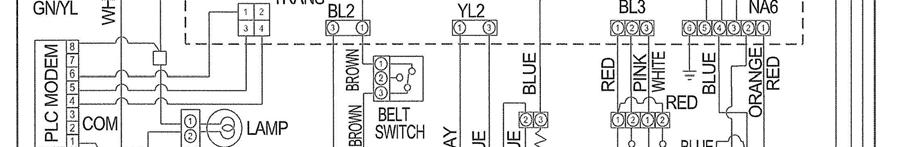
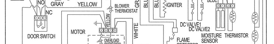
28 Electric Dryer Wiring Diagram Gas Dryer Wiring Diagram DLE7177WM/DLE7188WM Page 28 of 60 TRAINING MANUAL
29 DIAGNOSTIC TEST MODE The diagnostic test mode is for service testing only. Do not activate the heater manually with the door open or it will trip the thermostat attached to the heater. 1. Dryer must be in standby mode. (Plugged in, turned off) 2. Press and hold MORE TIME and LESS TIME, then press power. 3. Press START/PAUSE to advance to the next test. 4. Unplug the dryer for one minute after using the diagnostic mode. DLE7177WM/DLE7188WM Page 29 of 60 TRAINING MANUAL
30 DIAGNOSTIC TEST PROCEDURES The following pages will assist in troubleshooting and diagnosing issues with the dryer. Each test will list the appropriate precautionary measures along with symptoms and the conditions under which the testing should be performed. TEST V AC ELECTRICAL SUPPLY WARNING! SYMPTOM! CONDITION! Use insulated gloves to avoid electrical shock. No power, display off. Power on to dryer, controller connected. continued on next page DLE7177WM/DLE7188WM Page 30 of 60 TRAINING MANUAL
31 WARNING! SYMPTOM! CONDITION! Use insulated gloves to avoid electrical shock. Check the TAB RELAY connections. Power on to dryer, controller connected. POWER CONNECTION CONNECTION STATUS (Electric) CONNECTION STATUS (Electric) DLE7177WM/DLE7188WM Page 31 of 60 TRAINING MANUAL
32 If the power connection is reversed, the dryer will not operate and components can be damaged. CONNECTION STATUS REVERSED (Incorrect) (Electric) CONNECTION STATUS REVERSED (Incorrect) (Gas) DLE7177WM/DLE7188WM Page 32 of 60 TRAINING MANUAL
33 TEST 2 Thermistor Test (Power Off) WARNING! SYMPTOM! CONDITION! Use insulated gloves to avoid electrical shock. te1 and te2 error codes occur during the test. Heater does not turn off. Significant difference between actual and sensed temperature. Power off. Table Thermistor resistance/temperature DLE7177WM/DLE7188WM Page 33 of 60 TRAINING MANUAL
34 TEST 3 Motor Test WARNING! SYMPTOM! CONDITION! Discharge (see below) before measuring resistance. Motor, fan, and heater do not function. Turn power off, unplug dryer, and discharge by shorting line and neutral to ground at the end of the power cord. DLE7177WM/DLE7188WM Page 34 of 60 TRAINING MANUAL
35 TEST 4 Moisture Sensor Test WARNING! SYMPTOM! CONDITION! Discharge (see below) before measuring resistance. Dryness of clothing does not match set dry level. Turn power off, unplug dryer, and discharge by shorting line and neutral to ground at the end of the power cord. Measure resistance. Table IMC Ratio and Display Value (IMC = Initial Moisture Content) DLE7177WM/DLE7188WM Page 35 of 60 TRAINING MANUAL
36 TEST 5 Door Switch Test WARNING! SYMPTOM! CONDITION! Discharge before measuring resistance. Door opening not sensed (dryer runs with door open). Turn dryer off, unplug, discharge, and measure resistance. DLE7177WM/DLE7188WM Page 36 of 60 TRAINING MANUAL
37 TEST 6 Heater Switch (Electric Dryer Only) WARNING! SYMPTOM! CONDITION! Discharge before measuring resistance. Heater does not operate. Turn power off, unplug, discharge, and measure resistance. DLE7177WM/DLE7188WM Page 37 of 60 TRAINING MANUAL
38 TEST 7 Gas Valve Test (Gas Dryer Only) WARNING! SYMPTOM! CONDITION! Use insulated gloves to avoid electrical shock. Heater does not operate. Power on. DLE7177WM/DLE7188WM Page 38 of 60 TRAINING MANUAL
39 TEST 8 Semiconductor (Sensor) Test WARNING! SYMPTOM! CONDITION! Discharge before measuring resistance. Resistance is not 300Ω ± 20Ω Turn power off, unplug, discharge, and measure resistance. DLE7177WM/DLE7188WM Page 39 of 60 TRAINING MANUAL


40 GAS CONVERSION (Natural to Propane) WARNING! Improper installation and/or adjustment of orifices and gas valves can result in fire, explosion, and suffocation. Installation and adjustment should be performed ONLY by a trained, licensed, and certified gasfitter. NOTICE! The dryer is shipped from the factory equipped for natural gas. 1. Close the adjustment screw. Notice there is a nut on the adjustment screw. This nut is secured to the thread with a sealing compound. The nut is pre-positioned to the place the valve would be properly adjusted for LP. It s purpose is to provide a shoulder for positioning the adjustment screw if the dryer is converted from natural gas to propane. NOTE: The conversion should be performed by a licensed and certified gasfitter. DLE7177WM/DLE7188WM Page 40 of 60 TRAINING MANUAL
![GAS CONVERSION (Natural to Propane) continued 2. Replace the orifice. (See photo, previous page.] You ll have to remove the top plate and front cover to change the orifice.](/docs-images/93/113356539/images/41-0.jpg "Installing the correct orifice is critical! This should be performed ONLY by trained, licensed, and certified service personnel. 3.")
41 GAS CONVERSION (Natural to Propane) continued 2. Replace the orifice. (See photo, previous page.] You ll have to remove the top plate and front cover to change the orifice. Installing the correct orifice is critical! This should be performed ONLY by trained, licensed, and certified service personnel. 3. The conversion kit includes a propane orifice, complete instructions for making the conversion, and a label indicating the conversion kit has been installed. All conversion work, including testing and adjusting, must be completed by a trained, licensed, and certified gasfitter. DLE7177WM/DLE7188WM Page 41 of 60 TRAINING MANUAL
, the igniter is turned off and valve two is opened. If the flame detector does not detect ignition, valve two is closed and the process is restarted.")
42 GAS VALVE OPERATION The gas valve is a two-stage valve. When the ignition sequence begins, the igniter is turned on and valve one opens. When the igniter reaches 370 F (188 C), the igniter is turned off and valve two is opened. If the flame detector does not detect ignition, valve two is closed and the process is restarted. If ignition occurs as planned, the drying cycle will operate. GAS IGNITION SEQUENCE GAS VALVE CONSTRUCTION IGNITION FLOW CHART DLE7177WM/DLE7188WM Page 42 of 60 TRAINING MANUAL

43 TOP PLATE DISASSEMBLY and REPAIR INSTRUCTIONS 1. Remove three screws along the back of the top (cover) plate. 2. Slide the top plate backward. 3. Lift the top plate off and set it aside. DLE7177WM/DLE7188WM Page 43 of 60 TRAINING MANUAL


44 CONTROL PANEL 1. Remove two screws, one on each corner of the control panel. 2. Disconnect all connectors. NOTE: The connectors are all different to prevent misassembly. 3. Pull the control panel upward, then forward. Be sure to disengage all the plastic tabs along the top. 4. Lay the control panel on its face on a soft, protective cloth. 5. Remove nine screws on the display PWB. 6. Remove four screws on the main PWB. 7. Disassemble the control panel. DLE7177WM/DLE7188WM Page 44 of 60 TRAINING MANUAL


45 FRONT CABINET 1. Remove the top plate. 2. Remove the control panel. 3. Remove the door, if necessary for the repair. 4. Remove two screws in the bottom of the door opening. 5. Remove four screws from the top of the front cabinet. 6. Tilt the front away from the dryer and disconnect the door switch wire harness. DOOR REVERSAL 1. Remove two screws that hold the door. Remove the door and set it aside on a soft, protective cloth. Save the hinge shim. 2. Remove two screws near the latch. 3. Remove two screws and the latch piece. 4. Rotate everything 180 and reinstall so the door opens from the other side. DLE7177WM/DLE7188WM Page 45 of 60 TRAINING MANUAL
 and electrode sensor (bottom). 4. Remove the four screws holding the front assembly. 5.")


46 TUB FRONT 1. Remove the top plate. 2. Remove the front cabinet. 3. Disconnect the door lamp (top) and electrode sensor (bottom). 4. Remove the four screws holding the front assembly. 5. Lift the tub front up and away. DRUM, BELT, and PULLEY 1. Remove the drum front. 2. Reach in and remove the belt from the motor and pulley. 3. Lift the drum out through the front of the dryer. The belt will still be around the drum. 4. To replace the drum, put the belt around it and set into the dryer to rest on the two rubber wheels on the tub back. Let the belt hang. 6. Replace the tub front, holding the drum up so it can set on the two rubber wheels on the tub front. 7. Make sure the belt is around the circumference of the drum near the point where it usually rides. 8. Reach in through the front or the side and loop the belt around the motor shaft and the pulley. Rotate the drum by hand a couple of turns to seat it. DLE7177WM/DLE7188WM Page 46 of 60 TRAINING MANUAL


47 DRUM LAMP The drum light can usually be changed without a major disassembly, unless the bulb is frozen in the socket. If the bulb can t be changed using this procedure, you ll have to remove the front cover and the lampholder to get to the socket. 1. Open the door. 2. Hold the lamp shield in place and remove the screw. 3. Slide the shield toward the screw and remove it. 4. Unscrew the bulb and replace it with a 15-watt, 120 V, candelabra-base bulb. 5. Replace the shield and screw. Notice the bulb holder has feet that hold it in place and tabs to keep it positioned properly. The socket can be removed and replaced by squeezing the tabs and pulling the bulb and socket into the housing. Press it back into place after changing the bulb. DLE7177WM/DLE7188WM Page 47 of 60 TRAINING MANUAL
 Remove the knockout on the left, right*, or bottom, as necessary. * Right vent option not available on gas dryers due to internal piping interference. (B) Insert the replacement pipe.")
48 VENT REPLACEMENT 1. Use the VENT KIT to change the exhaust direction. (Part # 383EEL9001B) On the back of the dryer, remove the screw securing the exhaust duct. 2. (A) Remove the knockout on the left, right*, or bottom, as necessary. * Right vent option not available on gas dryers due to internal piping interference. (B) Insert the replacement pipe. (C) Attach the pipe with a screw. 3. Pre-assemble the elbow and a replacement duct and secure the joint with duct tape. 4. Insert the pre-assembled elbow into the dryer through the vent hole and connect it to the internal pipe. 5. Tear off some pieces of duct tape and secure that joint as well. 6. Connect the pipe to the exhaust duct. DLE7177WM/DLE7188WM Page 48 of 60 TRAINING MANUAL


49 FILTER ASSEMBLY and MOISTURE SENSOR 1. Remove the lint filter. 2. Remove three screws holding the cover grid. 3. Remove the cover grid. 4. Disconnect the electrode sensors. BACK COVER 1. Remove the top plate. 2. Remove the front cover. 3. Remove the tub front. 4. Remove the drum. 5. Remove 7 screws. 6. Remove the back cover. DLE7177WM/DLE7188WM Page 49 of 60 TRAINING MANUAL


50 AIR DUCT 1. Remove the top plate. 2. Remove the front cover. 3. Remove the filter. 4. Remove 2 screws at the top of the air duct. 5. Remove the air duct. DLE7177WM/DLE7188WM Page 50 of 60 TRAINING MANUAL
 5.")


51 ROLLERS 1. Remove the top plate. 2. Remove the front cover. 3. Remove the tub front. 4. Remove the drum (if replacing the back rollers.) 5. Use an open-end wrench to remove and replace the shaft and roller. NOTE: If the shaft is OK and you are replacing only the roller, you can squeeze the triangular retainer to remove and replace the roller without removing the shaft from the machine. Be sure to install the small bushings. These must be between the roller and the retainer on both sides of the roller. See photo. DLE7177WM/DLE7188WM Page 51 of 60 TRAINING MANUAL

52 BLOWER HOUSING 1. Remove the top plate. 2. Remove the front cover. 3. Remove the tub front. 4. Remove the drum. 5. Remove the two screws and the cover on the air guide. 6. Remove the nut and washer on the blower shaft. 7. Remove the fan from the shaft. 8. Press down the hooked end of the clamps and remove them. 9. Disconnect and remove the motor. DLE7177WM/DLE7188WM Page 52 of 60 TRAINING MANUAL
53 EXPLODED VIEW (Control Panel and Top Plate Assembly) DLE7177WM/DLE7188WM Page 53 of 60 TRAINING MANUAL
54 EXPLODED VIEW (Cabinet and Door Assembly) DLE7177WM/DLE7188WM Page 54 of 60 TRAINING MANUAL

55 EXPLODED VIEW (Drum and Motor Electric Model) DLE7177WM/DLE7188WM Page 55 of 60 TRAINING MANUAL
56 EXPLODED VIEW (Drum and Motor Gas Model) DLE7177WM/DLE7188WM Page 56 of 60 TRAINING MANUAL
57 PARTS LIST DLE8377NM DLE8377WM DLG8388NM DLG8388WM Loc Description Part No Part No Part No Part No *001 Owner's Manual 3829EL3009B 3829EL3009B 3829EL3009B 3829EL3009B *002 Box, Carton 3890EZ3613A 3890EZ3613A 3890EZ3613A 3890EZ3613A *004 Manual, Service 3828EL3005D 3828EL3005D 3828EL3005D 3828EL3005D A110 Panel Assembly, Control 3721EL0009C 3721EL0009A 3721EL0009D 3721EL0009B A120 PCB Assembly, Display 6871EL1011A 6871EL1011A 6871EL1011B 6871EL1011B A130 PCB Assembly, Main 6871EL1013C 6871EL1013C 6871EL1013D 6871EL1013D A140 Knob Assembly 4941ER3005A 4941ER3005A 4941ER3005A 4941ER3005A A210 Plate Assembly, Top 3457ER1006X 3457ER1006D 3457ER1006X 3457ER1006D A211 Plate, Upper 3300EL2001E 3300EL2001A 3300EL2001E 3300EL2001A A300 Bracket, Hinge 4810EL3006A 4810EL3006A 4810EL3006A 4810EL3006A A305 Bracket, Hinge 4810EL3006B 4810EL3006B 4810EL3006B 4810EL3006B A310 Cabinet Cover Assembly 3551EL0009B 3551EL0009A 3551EL0009B 3551EL0009A A320 Locker Assembly 4027EL1001A 4027EL1001A 4027EL1001A 4027EL1001A A330 Switch, Micro 6601EL3001A 6601EL3001A 6601EL3001A 6601EL3001A A330 Safety Switch Assembly 6601EL3001A 6601EL3001A 6601EL3001A 6601EL3001A A390 Frame Assembly 3211EL1004A 3211EL1004A 3211EL1004A 3211EL1004A A400 Door Assembly 3581EL0004A 3581EL0004A 3581EL0004A 3581EL0004A A410 Locker, Hook 4026EL3007A 4026EL3007A 4026EL3007A 4026EL3007A A420 Outer Door Frame 3212EL1015A 3212EL1015A 3212EL1015A 3212EL1015A A430 Hinge 4774EL2001A 4774EL2001A 4774EL2001A 4774EL2001A A450 Inner Door Frame 3212EL1005B 3212EL1005B 3212EL1005B 3212EL1005B A460 Gasket 4986EL2004A 4986EL2004A 4986EL2004A 4986EL2004A A500 Cabinet Assembly 3091EL0003P 3091EL0003M 3091EL0003Q 3091EL0003N A510 Cap (Knockout cover) 5006EL3001G 5006EL3001D 5006EL3001G 5006EL3001D A520 Bracket, Base 4810EL3001A 4810EL3001A 4810EL3001A 4810EL3001A A525 Bracket, Base 4810EL3009A 4810EL3009A 4810EL3009A 4810EL3009A A530 Bracket, Base 4810EL3009B 4810EL3009B 4810EL3009B 4810EL3009B A540 Leg 4778EL3001A 4778EL3001A 4778EL3001A 4778EL3001A A560 Cover, Guide 3550EL3007A 3550EL3007A 6411ER1005B 6411ER1005B A570 Cover, Safety 3550EL3002A 3550EL3002A A600 HARNESS, PWB 6877EL1019B 6877EL1019B 6877EL1020B 6877EL1020B A700 Rack 3750EL1001B 3750EL1001B 3750EL1001B 3750EL1001B A800 Parts As by (Side Vent Kit) 383EEL9001B 383EEL9001B 383EEL9001B 383EEL9001B F110 Heater Assembly (Elec) 5301EL1001G 5301EL1001G F120 Bracket, Heater 4810EL1007A 4810EL1007A F130 Thermostat 6931EL3003D 6931EL3003D F140 Thermostat Assembly 6931EL3001E 6931EL3001E F200 Duct Assembly 5209EL1001C 5209EL1001C 5209EL1001D 5209EL1001D K100 Tub Assembly, Drum 3045EL1002E 3045EL1002E 3045EL1002E 3045EL1002E K120 Lifter 4432EL1002B 4432EL1002B 4432EL1002B 4432EL1002B K130 Belt, Poly V 4400EL2001A 4400EL2001A 4400EL2001A 4400EL2001A DLE7177WM/DLE7188WM Page 57 of 60 TRAINING MANUAL
58 DLE8377NM DLE8377WM DLG8388NM DLG8388WM Loc Description Part No Part No Part No Part No K140 Gasket 4036EL3001A 4036EL3001A 4036EL3001A 4036EL3001A K210 Tub, Drum (Front) 3044EL1001A 3044EL1001A 3044EL1001B 3044EL1001B K221 Lamp, Incand., Assembly 6913EL3002C 6913EL3002C 6913EL3002C 6913EL3002C K222 Lamp, Incandescent, Bulb 6913EL3001A 6913EL3001A 6913EL3001A 6913EL3001A K230 Cover, Lamp 3550EL2001A 3550EL2001A 3550EL2001A 3550EL2001A K240 Duct Assembly 5209EL1002A 5209EL1002A 5209EL1002A 5209EL1002A K250 Roller Assembly 4581EL2002A 4581EL2002A 4581EL2002A 4581EL2002A K251 Roller Assembly 4581EL3001A 4581EL3001A 4581EL3001A 4581EL3001A K310 Filter Assembly, Lint 5231EL1003B 5231EL1003B 5231EL1003B 5231EL1003B K320 Cover, Guide 3550EL1006B 3550EL1006B 3550EL1006B 3550EL1006B K330 Guide, Filter 4974EL1003B 4974EL1003B 4974EL1003B 4974EL1003B K340 Sensor 6500EL3001A 6500EL3001A 6500EL3001A 6500EL3001A K350 Cable & Wire 6631EL3003B 6631EL3003B 6631EL3003B 6631EL3003B K360 Holder 4930EL2004B 4930EL2004B 4930EL2004B 4930EL2004B K400 Tub, Drum (Rear) 3044EL0002B 3044EL0002B 3044EL0002B 3044EL0002B K510 Casing Assembly 5835EL1002A 5835EL1002A 5835EL1002A 5835EL1002A K520 Housing As by, Blower 3661EL1001E 3661EL1001E 3661EL1001E 3661EL1001E K530 Duct Assembly 5209EL1006A 5209EL1006A 5209EL1006A 5209EL1006A K540 Guide Assembly 4975EL3001A 4975EL3001A 4975EL3001A 4975EL3001A K550 Thermistor, NTC 6323EL2001B 6323EL2001B 6323EL2001B 6323EL2001B K560 Thermostat 6931EL3002A 6931EL3002A 6931EL3002A 6931EL3002A K600 Bracket, Motor 4810EL1002A 4810EL1002A 4810EL1002A 4810EL1002A K610 Motor, Unclassified 4681EL1002A 4681EL1002A 4681EL1002A 4681EL1002A K620 Clamp 4860EL3001A 4860EL3001A 4860EL3001A 4860EL3001A K640 Switch, Micro 3W40025Q 3W40025Q 3W40025Q 3W40025Q K650 Pulley Assembly, Motor 4561EL3002A 4561EL3002A 4561EL3002A 4561EL3002A K651 Pulley, Idle 4560EL3001A 4560EL3001A 4560EL3001A 4560EL3001A M110 Valve Assembly, Gas 5221EL2002A 5221EL2002A M140 Guide, Burner 4974EL1001A 4974EL1001A M141 Bracket, Base 4810EL3002A 4810EL3002A M150 Pipe Assembly 5201EL3001A 5201EL3001A M160 Igniter 5318EL3001A 5318EL3001A M170 Orifice, Natural Gas 4948EL4001B 4948EL4001B M171 Orifice, Propane 4948EL4002B 4948EL4002B M180 Connector, Mech, Pipe 4932EL4001A 4932EL4001A M181 Seal 4036EL3002A 4036EL3002A M190 Pipe Assembly 5201EL2001A 5201EL2001A M210 Funnel 3016EL1001A 3016EL1001A M220 Thermostat Assembly 6931EL3004B 6931EL3004B M230 Thermostat Assembly 6931EL3003C 6931EL3003C M240 Sensor Assembly 6501EL3001A 6501EL3001A M250 Supporter, Holder 4980EL3001A 4980EL3001A DLE7177WM/DLE7188WM Page 58 of 60 TRAINING MANUAL
59 (this page intentionally blank)
60 2006 LG Electronics, Inc. Printed in the USA
SERVICE MANUAL ELECTRIC & GAS DRYER MODEL : DLE5911W DLE2511W DLE5932W DLE5932S DLE2532W DLE0332W
 Website:http://www.LGservice.com [For U.S.A] www.lg.ca [For Canada] ELECTRIC & GAS DRYER SERVICE MANUAL CAUTION READ THIS MANUAL CAREFULLY TO DIAGSE TROUBLES CORRECTLY BEFORE OFFERING SERVICE. MODEL :
SERVICE MANUAL ELECTRIC & GAS DRYER MODEL : DLE2512W/DLG2522W DLE2514W/DLG2524W CAUTION
 Website:http://www.LGservice.com [For U.S.A] www.lg.ca [For Canada] ELECTRIC & GAS DRYER SERVICE MANUAL CAUTION READ THIS MANUAL CAREFULLY TO DIAGSE TROUBLES CORRECTLY BEFORE OFFERING SERVICE. MODEL :
SERVICE MANUAL ELECTRIC & GAS DRYER MODEL : DLE5977W/DLG5988W DLE5977B/DLG5988B DLE3777W/DLG3788W CAUTION
 Website:http://www.LGservice.com [For U.S.A] www.lg.ca [For Canada] ELECTRIC & GAS DRYER SERVICE MANUAL CAUTION READ THIS MANUAL CAREFULLY TO DIAGSE TROUBLES CORRECTLY BEFORE OFFERING SERVICE. MODEL :
TECH SHEET - DO NOT DISCARD PAGE
 TECH SHEET - DO NOT DISCARD PAGE 1 3. If this test mode has been entered successfully, all indicators on the console are illuminated for 5 seconds with 8:88 showing in the Estimated Time Remaining three-digit
Please read the following installation instructions first after purchasing this product or transporting it to another location.
 0 INSTALLATION INSTALLATION Installation Overview Please read the following installation instructions first after purchasing this product or transporting it to another location. Check and choose the proper
Home Stack Washer/Dryers
 Home Stack Washer/Dryers Refer to Page 3 for Model Numbers Parts SWD456C_806093 www.alliancelaundry.com Part No. 806093R1 December 2016 Table of Contents Title Page Parts Ordering Information... 2 Serial
Homestyle Stack Washer/Dryers
 Homestyle Stack Washer/Dryers Refer to Page 3 for Model Numbers Parts SWD456C_806105 www.alliancelaundry.com Part No. 806105R1 November 2015 Table of Contents Title Page Parts Ordering Information...
Dryer. User manual DV22K6800** DV22K A-00_EN (US)_ indd :15:41
_ indd :15:41") Dryer User manual DV22K6800** DV22K6800-03650A-00_EN (US)_151211.indd 1 2015-12-11 7:15:41 Before installation Read through the following instructions before installing the dryer, and keep this manual
Dryer User manual DV22K6800** DV22K6800-03650A-00_EN (US)_151211.indd 1 2015-12-11 7:15:41 Before installation Read through the following instructions before installing the dryer, and keep this manual
ELECTRIC & GAS DRYER SERVICE MANUAL
 Website: http://www.sears.com ELECTRIC & GAS DRYER SERVICE MANUAL CAUTION READ THIS MANUAL CAREFULLY IN ORDER TO PROPERLY DIAGSE PROBLEMS AND TO SAFELY PROVIDE QUALITY SERVICE ON THESE DRYERS. MODEL :
Home Stack Washer/Dryers
 Home Stack Washer/Dryers Refer to Page 3 for Model Numbers Parts SWD456C_806093 www.alliancelaundry.com Part No. 806093R4 September 2018 Table of Contents Title Page Parts Ordering Information... 2 Serial
TECH SHEET DO NOT DISCARD PAGE 1. If unsuccessful entry into diagnostic mode, actions can be taken for specific indications:
 TECH SHEET DO NOT DISCARD PAGE 1 WARNING Electrical Shock Hazard Disconnect power before servicing. Replace all parts and panels before operating. Failure to do so can result in death or electrical shock.
27" Gas Dryer MODELS: MGDB950YW3 (White) MGDB950YG3 (Cosmetallic) 05/31/ Maytag Part No. W Rev. A
 MGDB950YG3 (Cosmetallic) 05/31/ Maytag Part No. W Rev. A") 27" Gas Dryer MODELS: MGDB950YW3 (White) MGDB950YG3 (Cosmetallic) 05/31/2013 2013 Maytag Part W10617393 Rev. A TOP AND CONSOLE PARTS 05/31/2013 2 Part W10617393 Rev. A TOP AND CONSOLE PARTS Part Description
27" Gas Dryer MODELS: MGDB950YW3 (White) MGDB950YG3 (Cosmetallic) 05/31/2013 2013 Maytag Part W10617393 Rev. A TOP AND CONSOLE PARTS 05/31/2013 2 Part W10617393 Rev. A TOP AND CONSOLE PARTS Part Description
Home Stacked Washer/Dryer
 Home Stacked Washer/Dryer Refer to Page 3 for Model Numbers Parts SWD443C_802107 www.comlaundry.com Part No. 802107R6 August 2014 Table of Contents Title Page Parts Ordering Information... 2 Serial Plate
Homestyle Stacked Washer/Dryer
 Homestyle Stacked Washer/Dryer Parts Refer to Page 3 for Model Numbers SWD452C_802847 www.comlaundry.com Part No. 802847R8 August 2012 Table of Contents Title Page Parts Ordering Information... 2 Nameplate
COMPACT DRYER GDZ5-1 Training Presentation
 HAIER COMPACT DRYER GDZ5-1 Training Presentation HAIER COMPACT DRYER GDZ5-1 11 lbs. Electric Dryer Stackable Built in Free Standing 4.13cu ft Stainless Steel Drum Dual Temperature Operation Dry Time Selector
Homestyle Stacked Washer/ Dryer
 Homestyle Stacked Washer/ Dryer Parts Refer to Page 3 for Model Numbers SWD441C_801998 www.alliancelaundry.com Part No. 801998R6 January 2018 Table of Contents Title Page Parts Ordering Information...
29" GAS DRYER MODELS: MGD7000AW1 (White) MGD7000AG1 (Cosmetallic) 07/02/ Maytag Part No. W Rev. A
 MGD7000AG1 (Cosmetallic) 07/02/ Maytag Part No. W Rev. A") 29" GAS DRYER MODELS: MGD7000AW1 (White) MGD7000AG1 (Cosmetallic) 07/02/2013 2013 Maytag Part W10624907 Rev. A TOP AND CONSOLE PARTS 07/02/2013 2 Part W10624907 Rev. A TOP AND CONSOLE PARTS Part Description
29" GAS DRYER MODELS: MGD7000AW1 (White) MGD7000AG1 (Cosmetallic) 07/02/2013 2013 Maytag Part W10624907 Rev. A TOP AND CONSOLE PARTS 07/02/2013 2 Part W10624907 Rev. A TOP AND CONSOLE PARTS Part Description
Installation Instructions
 Installation Instructions Before you begin... 2 Location... 2 Recommended grounding instructions... 2 Electrical requirements... 2 Exhaust requirements... 3 Water supply and drain requirements... 3 Please
DRYER INSTALLATION INSTRUCTIONS
 DRYER INSTALLATION INSTRUCTIONS Table of Contents DRYER SAFETY... 1 INSTALLATION REQUIREMENTS... 2 Tools and Parts... 2 Location Requirements... 3 Electrical Requirements... 5 INSTALLATION INSTRUCTIONS...
27 ELECTRIC & GAS DRYERS
 CONSUMER SERVICES TECHNICAL EDUCATION GROUP PRESENTS L-63 27 ELECTRIC & GAS DRYERS JOB AID Part No. 4322260 I INTRODUCTION This Job Aid, 27 ELECTRIC & GAS DRYERS, (Part No. 4322260), provides specific
TOP AND CONSOLE PARTS
 TOP AND CONSOLE PARTS 27" ELECTRIC DRYER 6 12 Printed in U.S.A. (GG)(bay) 1 Part No. Rev. A TOP AND CONSOLE PARTS 1 Literature Parts W10392124 Installation, Diagnostic Guide W10388780 Guide, Use & Care
COMMERCIAL STACKED GAS DRYER/WASHER
 COMMERCIAL STACKED GAS DRYER/WASHER MODEL NO. CGT8000XQ0 c 2012 WHIRLPOOL CORPORATION 5 12 Litho In U.S.A. (CMS) (bay) Part No. Rev. H CONTROL PANEL PARTS 2 CONTROL PANEL PARTS 1 Literature Parts W10335467
Homestyle Stacked Washer/Dryer
 Homestyle Stacked Washer/Dryer Parts Refer to Page 3 for Model Numbers SWD443C_801802 www.alliancelaundry.com Part No. 801802R8 January 2018 Table of Contents Title Page Parts Ordering Information...
ELECTRIC DRYER INSTALLATION INSTRUCTIONS
 ELECTRIC DRYER INSTALLATION INSTRUCTIONS Table of Contents DRYER SAFETY... 2 INSTALLATION REQUIREMENTS... 3 Tools and Parts... 3 LOCATION REQUIREMENTS... 4 ELECTRICAL REQUIREMENTS... 6 INSTALL LEVELING
ELECTRIC DRYER INSTALLATION INSTRUCTIONS
 ELECTRIC DRYER INSTALLATION INSTRUCTIONS Table of Contents DRYER SAFETY... 2 INSTALLATION REQUIREMENTS... 3 Tools and Parts... 3 LOCATION REQUIREMENTS... 4 ELECTRICAL REQUIREMENTS... 5 INSTALL LEVELING
27" GAS DRYER MODELS: 7MWGD87HEDC0 (Chrome Shadow) 08/19/ Whirlpool Corporation Part No. W Rev. A
 08/19/ Whirlpool Corporation Part No. W Rev. A") 27" GAS DRYER MODELS: 7MWGD87HEDC0 (Chrome Shadow) 08/19/2014 2014 Whirlpool Corporation Part W10738517 Rev. A TOP AND CONSOLE PARTS 08/19/2014 2 Part W10738517 Rev. A TOP AND CONSOLE PARTS 1 Literature
27" GAS DRYER MODELS: 7MWGD87HEDC0 (Chrome Shadow) 08/19/2014 2014 Whirlpool Corporation Part W10738517 Rev. A TOP AND CONSOLE PARTS 08/19/2014 2 Part W10738517 Rev. A TOP AND CONSOLE PARTS 1 Literature
DISCOVERY WASHER TRAINING MANUAL
 www.lgeservice.com DISCOVERY WASHER TRAINING MANUAL CAUTION! READ THIS MANUAL CAREFULLY BEFORE DIAGNOSING OR SERVICING THIS PRODUCT. Customer Service (and Part Sales) (800) 243-0000 Technical Support (and
INSTALLATION GUIDE Dual Fuel Ranges
 INSTALLATION GUIDE Dual Fuel Ranges Contents Wolf Dual Fuel Ranges......................... 3 Safety Instructions............................ 4 Dual Fuel Range Specifications.................. 5 Dual Fuel
IMPORTANT SAFETY INFORMATION! WARNING ALWAYS keep electric cords, home furnishings, drapes, clothing, papers, or other combustibles at least 3 feet (0
 Electric Fireplace Factory Model: EF-30D CONSUMER SAFETY INFORMATION Read this manual before installing and operating this appliance Failure to follow these instructions may result in electric shock, fire
GAS DRYER MODELS: MGD8200FW0 (White) MGD8200FC0 (Chrome Shadow) 05/24/ Maytag Part No. W Rev. A
 MGD8200FC0 (Chrome Shadow) 05/24/ Maytag Part No. W Rev. A") GAS DRYER MODELS: MGD8200FW0 (White) MGD8200FC0 (Chrome Shadow) 05/24/2016 2016 Maytag Part W10884161 Rev. A TOP AND CONSOLE PARTS 05/24/2016 2 Part W10884161 Rev. A TOP AND CONSOLE PARTS Part Description
GAS DRYER MODELS: MGD8200FW0 (White) MGD8200FC0 (Chrome Shadow) 05/24/2016 2016 Maytag Part W10884161 Rev. A TOP AND CONSOLE PARTS 05/24/2016 2 Part W10884161 Rev. A TOP AND CONSOLE PARTS Part Description
DIAGNOSTIC GUIDE DIAGNOSTIC TEST DISPLAY FAULT/ERROR CODES IMPORTANT. Activating the Diagnostic Test Mode. Before servicing, check the following:
 TECH SHEET - DO NOT DISCARD PAGE 1 DIAGNOSTIC GUIDE Before servicing, check the following: IMPORTANT Electrostatic Discharge (ESD) Sensitive Electronics ESD problems are present everywhere. ESD may damage
27" GAS DRYER MODELS: WGD95HEDW0 (White) WGD95HEDC0 (Chrome Shadow) 05/13/ Whirlpool Corporation Part No. W Rev.
 WGD95HEDC0 (Chrome Shadow) 05/13/ Whirlpool Corporation Part No. W Rev.") 27" GAS DRYER MODELS: WGD95HEDW0 (White) WGD95HEDC0 (Chrome Shadow) 05/13/2014 2014 Whirlpool Corporation Part W10710285 Rev. A TOP AND CONSOLE PARTS 05/13/2014 2 Part W10710285 Rev. A TOP AND CONSOLE
27" GAS DRYER MODELS: WGD95HEDW0 (White) WGD95HEDC0 (Chrome Shadow) 05/13/2014 2014 Whirlpool Corporation Part W10710285 Rev. A TOP AND CONSOLE PARTS 05/13/2014 2 Part W10710285 Rev. A TOP AND CONSOLE
DIAGNOSTIC GUIDE DAMP DRY TEST
 TECH SHEET - DO NOT DISCARD PAGE 1 Electrical Shock Hazard Disconnect power before servicing. Replace all parts and panels before operating. Failure to do so can result in death or electrical shock. IMPORTANT
27" GAS DRYER MODELS: MGD7100DW0 (White) MGD7100DC0 (Chrome Shadow) 05/08/ Maytag Part No. W Rev. A
 MGD7100DC0 (Chrome Shadow) 05/08/ Maytag Part No. W Rev. A") 27" GAS DRYER MODELS: MGD7100DW0 (White) MGD7100DC0 (Chrome Shadow) 05/08/2014 2014 Maytag Part W10712329 Rev. A TOP AND CONSOLE PARTS 05/08/2014 2 Part W10712329 Rev. A TOP AND CONSOLE PARTS Part Description
27" GAS DRYER MODELS: MGD7100DW0 (White) MGD7100DC0 (Chrome Shadow) 05/08/2014 2014 Maytag Part W10712329 Rev. A TOP AND CONSOLE PARTS 05/08/2014 2 Part W10712329 Rev. A TOP AND CONSOLE PARTS Part Description
COMMERCIAL STACKED. Supersedes repair parts list located behind lower panel on washer. Models: CGT8000AQ1 (White)
") PARTS LIST for COMMERCIAL STACKED Supersedes repair parts list located behind lower panel on washer Models: CGT8000AQ1 (White) FOR CUSTOMER SATISFACTION ALWAYS USE FACTORY SPECIFICATION PARTS 201210001
PARTS LIST for COMMERCIAL STACKED Supersedes repair parts list located behind lower panel on washer Models: CGT8000AQ1 (White) FOR CUSTOMER SATISFACTION ALWAYS USE FACTORY SPECIFICATION PARTS 201210001
TECH SHEET - DO NOT DISCARD PAGE 1 DIAGNOSTIC GUIDE
 TECH SHEET - DO NOT DISCARD PAGE 1 Electrical Shock Hazard Disconnect power before servicing. Replace all parts and panels before operating. Failure to do so can result in death or electrical shock. IMPORTANT
GAS DRYER MODELS: WGD8000DW0 (White) 03/30/ Whirlpool Corporation Part No. W Rev. C
 03/30/ Whirlpool Corporation Part No. W Rev. C") GAS DRYER MODELS: WGD8000DW0 (White) 03/30/2015 2015 Whirlpool Corporation Part W10743192 Rev. C TOP AND CONSOLE PARTS 03/30/2015 2 Part W10743192 Rev. C TOP AND CONSOLE PARTS Part Description 1 Literature
GAS DRYER MODELS: WGD8000DW0 (White) 03/30/2015 2015 Whirlpool Corporation Part W10743192 Rev. C TOP AND CONSOLE PARTS 03/30/2015 2 Part W10743192 Rev. C TOP AND CONSOLE PARTS Part Description 1 Literature
DIAGNOSTIC GUIDE DISPLAY FAULT/ERROR CODES E1 THERMISTOR OPEN IMPORTANT. Activating the Diagnostic Test Mode. Test Mode Functionality
 TECH SHEET - DO NOT DISCARD PAGE 1 DIAGNOSTIC GUIDE Electrical Shock Hazard Disconnect power before servicing. Replace all panels before operating. Failure to do so can result in death or electrical shock.
52 BERKSHIRE CEILING FAN
 52 BERKSHIRE CEILING FAN Owner s Manual Models #20223, 20224 If a problem cannot be remedied or you are experiencing difficulty in installation, please contact the Service Department: 1-877-459-3267, 9
e Bath Fan with Light User s Guide
 e Bath Fan with Light User s Guide abfl100rnl, BFL125RNL Item Stock Number(s): BFL100RNL, BFL125RNL IMPORTANT INSTRUCTIONS - OPERATING MANUAL READ AND SAVE THESE INSTRUCTIONS READ CAREFULLY BEFORE ATTEMPTING
52 CEILING FAN. Owner s Manual Models #50336, 50337
 52 CEILING FAN Owner s Manual Models #50336, 50337 If a problem cannot be remedied or you are experiencing difficulty in installation, please contact the Service Department: 1-877-706-3267, 9 a.m.- 5 p.m.
IMPORTANT INSTRUCTIONS - OPERATING MANUAL
 IMPORTANT INSTRUCTIONS - OPERATING MANUAL Models: AK80LSL, AK100LSL Exhaust Fan READ AND SAVE THESE INSTRUCTIONS READ CAREFULLY BEFORE ATTEMPTING TO ASSEMBLE, INSTALL, OPERATE OR MAINTAIN THE PRODUCT DESCRIBED.
GAS AND ELECTRIC DRYERS
 CONSUMER SERVICES TECHNICAL EDUCATION GROUP PRESENTS L-69 GAS AND ELECTRIC DRYERS Model Numbers: GGW9200L & GEW9200L JOB AID Part No. 8178071 FORWARD This Whirlpool Job Aid, Duet Gas and Electric Dryers,
GAS DRYER MODELS: (White) (Chrome Shadow) 01/28/ Sears Brands, LLC Part No. W Rev. A
 (Chrome Shadow) 01/28/ Sears Brands, LLC Part No. W Rev. A") GAS DRYER MODELS: 110.78132413 (White) 110.78133413 (Chrome Shadow) 01/28/2016 2016 Sears Brands, LLC Part W10865713 Rev. A TOP AND CONSOLE PARTS 01/28/2016 2 Part W10865713 Rev. A TOP AND CONSOLE PARTS
GAS DRYER MODELS: 110.78132413 (White) 110.78133413 (Chrome Shadow) 01/28/2016 2016 Sears Brands, LLC Part W10865713 Rev. A TOP AND CONSOLE PARTS 01/28/2016 2 Part W10865713 Rev. A TOP AND CONSOLE PARTS
Commercial Stacked Washer/ Dryers
 Commercial Stacked Washer/ Dryers Parts Refer to Page 3 for Model Numbers SWD446C_801771 www.comlaundry.com Part No. 801771R4 March 2010 Table of Contents Title Page Parts Ordering Information... 2 Nameplate
29 IN. (73.7 CM) ELECTRIC DRYER INSTALLATION INSTRUCTIONS DRYER SAFETY
 ELECTRIC DRYER INSTALLATION INSTRUCTIONS DRYER SAFETY") 9 IN. (7.7 CM) ELECTRIC DRYER INSTALLATION INSTRUCTIONS DRYER SAFETY... INSTALLATION INSTRUCTIONS... Tools and Parts... Location Requirements... Electrical Requirements... Electrical Connection...4 Venting
9 IN. (7.7 CM) ELECTRIC DRYER INSTALLATION INSTRUCTIONS DRYER SAFETY... INSTALLATION INSTRUCTIONS... Tools and Parts... Location Requirements... Electrical Requirements... Electrical Connection...4 Venting
CLOTHES DRYER Technical Information
 CLOTHES DRYER Technical Information IMPORTANT SAFETY NOTICE For Technicians only This service data sheet is intended for use by persons having electrical, electronic, and mechanical experience and knowledge
FIREPLACE INSTALLATION
 CHECK GAS TYPE Use proper gas type for the fireplace unit you are installing. If you have conflicting gas types, do not install fireplace. See retailer where you purchased the fireplace for proper fireplace
TOP AND CONSOLE PARTS For Models: LGQ9858PW0, LGQ9858PG0 (White/Grey) (Biscuit/Gold)
 (Biscuit/Gold)") TOP AND CONSOLE PARTS 29"GAS DRYER 5 04 Litho in U.S.A. (djc) 1 Part No. 1 Literature Parts LIT8535830 Instructions, Installation LIT8533770 Sheet, Cycle Feature LIT8522243 Use & Care Guide LIT3406661
TOP AND CONSOLE PARTS 29"GAS DRYER 5 04 Litho in U.S.A. (djc) 1 Part No. 1 Literature Parts LIT8535830 Instructions, Installation LIT8533770 Sheet, Cycle Feature LIT8522243 Use & Care Guide LIT3406661
Model PF 2030 Wide Area Vacuum Cleaner
 Model PF 2030 Wide Area Vacuum Cleaner OPERATING INSTRUCTIONS COMMERCIAL WIDE AREA SWEEPER VACUUM CONGRATULATIONS YOU HAVE JUST ACQUIRED A HIGH QUALITY VACUUM CLEANER. PLEASE READ THIS MANUAL CAREFULLY,
Technical Service Guide
 GE Consumer & Industrial Technical Service Guide December 2006 GE DRYER DSXH47EG DSXH47GG 31-9148 GE Appliances General Electric Company Louisville, Kentucky 40225 1 IMPORTANT SAFETY NOTICE The information
WASHER/DRYER CONTROL PANEL PARTS For Model: MET3800TW2 (White)
") WASHER/DRYER CONTROL PANEL PARTS WASHER/DRYER LAUNDRY SYSTEM 1 Literature Parts W10222378 Installation Instructions W10196552 Use & Care Guide W10117755 Sheet, Cycle Feature W10114285 Wire Diagram 2 3390688
WASHER/DRYER CONTROL PANEL PARTS WASHER/DRYER LAUNDRY SYSTEM 1 Literature Parts W10222378 Installation Instructions W10196552 Use & Care Guide W10117755 Sheet, Cycle Feature W10114285 Wire Diagram 2 3390688
TECHNICAL INFORMATION T1500 Series Clothes Dryers
 TECHNICAL INFORMATION T1500 Series Clothes Dryers 2003 Miele - Table of Contents 1.0 CONSTRUCTION & DESIGN 1.1 Appliance Overview - Vented 1 1.2 Appliance Overview Condenser Models 2 1.3 Controls Overview
Installation Instructions Dual Fuel Ranges
 Installation Instructions Dual Fuel Ranges E30DF74EPS E36DF76EPS E48DF76EPS 5995447082 2 Safety IMPORTANT SAFETY INSTRUCTIONS Safety Precautions Do not attempt to install or operate your unit until you
WASHER/DRYER CONTROL PANEL PARTS For Model: YWET3300SQ0 (Designer White)
") WASHER/DRYER CONTROL PANEL PARTS WASHER/DRYER LAUNDRY SYSTEM 1 Literature Parts Installation Instructions W10118289 English 8578179 English W10118304 Sheet, Cycle Feature W10113806 Wire Diagram 2 3390688
WASHER/DRYER CONTROL PANEL PARTS WASHER/DRYER LAUNDRY SYSTEM 1 Literature Parts Installation Instructions W10118289 English 8578179 English W10118304 Sheet, Cycle Feature W10113806 Wire Diagram 2 3390688
WASHER/DRYER CONTROL PANEL PARTS For Model: YWET3300SQ1 (Designer White)
") WASHER/DRYER CONTROL PANEL PARTS WASHER/DRYER LAUNDRY SYSTEM 1 Literature Parts Installation Instructions W10118289 English 8578179 English W10118304 Sheet, Cycle Feature W10117522 Wire Diagram 2 3390688
WASHER/DRYER CONTROL PANEL PARTS WASHER/DRYER LAUNDRY SYSTEM 1 Literature Parts Installation Instructions W10118289 English 8578179 English W10118304 Sheet, Cycle Feature W10117522 Wire Diagram 2 3390688
ELECTRIC DRYER INSTALLATION INSTRUCTIONS
 ELECTRIC DRYER INSTALLATION INSTRUCTIONS Para una version de estas instrucciones en español, visite www.whirlpool.com Table of Contents DRYER SAFETY... 2 Installation Requirements... 3 Tools and Parts...
Installation Electric Dryers Instructions 01
 Installation Electric Dryers Instructions 01 Questions? Call 800.GE.CARES (800.432.2737) or visit our Web site at: GEAppliances.com This is the safety alert symbol. This symbol alerts you to potential
WASHER/DRYER CONTROL PANEL PARTS
 WASHER/DRYER CONTROL PANEL PARTS WASHER/DRYER LAUNDRY SYSTEM 1 Literature Parts W10356098 Installation Instructions W10343071 Guide, Use & Care W10364010 Wiring Diagram W10343084 Energy Guide 2 3390688
Table of Contents What to Expect with Your Installation. Top Housing. Ceiling Plate. Tools Needed.
 Table of Contents Congratulations on purchasing your new Hunter ceiling fan! It will provide comfort and performance in your home or office for many years. This installation and operation manual contains
CONTENTS DESCRIPTION UNPACKING DIMENSIONS
 INSTALLATION INSTRUCTIONS Ventilating Fan ModelNo.FV-08VRE CONTENTS GENERAL SAFETY INFORMATION DESCRIPTION UNPACKING SUPPLIED ACCESSORIES DIMENSIONS WIRING DIAGRAM INSTALLATION (BETWEEN JOISTS MOUNTING)
COMMERCIAL ELECTRIC DRYER
 COMMERCIAL ELECTRIC DRYER MODEL MDE22PNAGW0 1 10 Litho In U.S.A. (BT)(bay) c 2010 WHIRLPOOL CORPORATION Part No. Rev. B TOP AND CONSOLE PARTS WIRING HARNESS PARTS 2 TOP AND CONSOLE PARTS 1 Literature Parts
INSTALLATION INSTRUCTIONS INSTRUCTIONS D INSTALLATION INSTRUCCIONES DE INSTALACIÓN
 EN FRONT LOAD DRYER FR SÉCHEUSE Á CHARGEMENT FRONTAL ES SECADORA DE CARGA FRONTAL INSTALLATION INSTRUCTIONS INSTRUCTIONS D INSTALLATION INSTRUCCIONES DE INSTALACIÓN 2 IMPORTANT SAFETY INSTRUCTIONS For
An occurrence of an Error will make a sound of error melody for 5sec and continuously show one of the Error Displays from the following errors.
 4. Troubleshooting 4-1. Error items and diagnostic codes An occurrence of an Error will make a sound of error melody for 5sec and continuously show one of the Error Displays from the following errors.
TECHNICAL INFORMATION T 15xx Dryers
 TECHNICAL INFORMATION T 15xx Dryers 2010 Miele USA Table of Contents 1.0 2.0 3.0 T 15xx Dryers Construction and Design... 5 1.1 Appliance Overview Vented Models... 5 1.2 Appliance Overview Condenser Models...
CLOTHES DRYER Technical Information
 CLOTHES DRYER Technical Information Due to possibility of personal injury or property damage, always contact an authorized technician for servicing or repair of this unit. Refer to Service Manual (DV456*,DV422*,DV400*)
Questions on Installation? Call: 800.GE.CARES (US) WARNING RISK OF FIRE 4" DIA. METAL DUCT (RECOMMENDED) 4" DUCT CLAMPS (2) OR 4" SPRING CLAMPS (2)
 WARNING RISK OF FIRE 4 DIA. METAL DUCT (RECOMMENDED) 4 DUCT CLAMPS (2) OR 4 SPRING CLAMPS (2)") Installation Instructions Electric Dryer 01 Questions on Installation? Call: 800.GE.CARES (US) www.geappliances.com (US) PEDESTALS FOR DRYERS (comes with individual installation instructions) Three models
Installation Instructions Electric Dryer 01 Questions on Installation? Call: 800.GE.CARES (US) www.geappliances.com (US) PEDESTALS FOR DRYERS (comes with individual installation instructions) Three models
W Model 1RKU2 w/optional Wall mount. Unit Model Weight (Lbs) Kilowatts Volts- Phase Amps Fan Output Heat Output
 Kilowatts Volts- Phase Amps Fan Output Heat Output") Operating Instructions & Parts Manual 1RKT2, 1RKT3, 1RKT4, 1RKT5, 1RKT9 and 1RKU2 Please read and save these instructions. Read carefully before attempting to assemble, install, operate or maintain the
Operating Instructions & Parts Manual 1RKT2, 1RKT3, 1RKT4, 1RKT5, 1RKT9 and 1RKU2 Please read and save these instructions. Read carefully before attempting to assemble, install, operate or maintain the
COMBINATION ELECTRIC FIREPLACE/HEATER Model #FP23-1A-AKM
 LOT NUMBER: DATE PURCHASED: / / USE AND CARE GUIDE COMBINATION ELECTRIC FIREPLACE/HEATER Model #FP23-1A-AKM If you have any questions regarding the use of this unit, or find that your fireplace/heater
P MODEL AIR CONDITIONER
 CONSUMER SERVICES TECHNICAL EDUCATION GROUP PRESENTS R-94 P MODEL AIR CONDITIONER JOB AID Part No. 8178039 FORWARD This Whirlpool Job Aid, P Model Air Conditioner (Part No. 8178039), provides the technician
2 PREPARE THE OPENING
 Installation Instructions 27 & 30 Electric Built-In Wall Ovens Questions? Call 1.800.GE.CARES (1.800.432.2737) or visit www.geappliances.com In Canada, call 1.800.561.3344 or visit www.geappliances.ca
ELECTRIC DRYER INSTALLATION INSTRUCTIONS
 ELECTRIC DRYER INSTLLTION INSTRUCTIONS Para una version de estas instrucciones en español, visite www.whirlpool.com Table of Contents DRYER SFETY... 2 Installation Requirements... 3 Tools and Parts...
Dacor Technical Service
 Attention: This manual is just a section from the complete Wall Oven Service Manual. If you find that you require the complete service manual, which includes exploded views and parts, use and care information
Installation Instructions Part No , Part No Part No
 Torsion-Flex Motor mount for PSC motors and Rigid-Mount for ECM motors Replacement Kit Cancels: New Installation Instructions Part No. 327752-401, Part No. 327753-401 Part No. 327754-401 IIK-310A-45-11
WASHING MACHINE READ THIS MANUAL CAREFULLY TO DIAGNOSE TROUBLE CORRECTLY BEFORE OFFERING SERVICE.
 website : http://www.lgeservice.com e-mail : http://lgeservice.com/techsup.html WASHING MACHINE SERVICE MANUAL CAUTION READ THIS MANUAL CAREFULLY TO DIAGSE TROUBLE CORRECTLY BEFORE OFFERING SERVICE. MODEL
WASHER/DRYER CONTROL PANEL PARTS
 WASHER/DRYER CONTROL PANEL PARTS WASHER/DRYER LAUNDRY SYSTEM 1 3398879 Harness, Console Wiring (Automatic) (Includes Illus. 1A, 1B & 1C) 1A 3350130 Plug, Terminal (2 Way) (Connects With Main Dryer Harness)
Questions on Installation? Call: 800.GE.CARES (US) WARNING RISK OF FIRE TOOLS YOU WILL NEED 4" DIA. METAL DUCT (RECOMMENDED)
 WARNING RISK OF FIRE TOOLS YOU WILL NEED 4 DIA. METAL DUCT (RECOMMENDED)") Installation Instructions Electric Dryer 04 Questions on Installation? Call: 800.GE.CARES (US) www.geappliances.com (US) BEFORE YOU BEGIN Read these instructions completely and carefully. IMPORTANT- IMPORTANT-
Installation Instructions Electric Dryer 04 Questions on Installation? Call: 800.GE.CARES (US) www.geappliances.com (US) BEFORE YOU BEGIN Read these instructions completely and carefully. IMPORTANT- IMPORTANT-
INSTALLATION INSTRUCTIONS FOR FREESTANDING DUAL FUEL
 INSTALLATION AND SERVICE MUST BE PERFORMED BY A QUALIFIED INSTALLER. IMPORTANT: SAVE FOR LOCAL ELECTRICAL INSPECTOR'S USE. READ AND SAVE THESE INSTRUCTIONS FOR FUTURE REFERENCE. If the information in this
48 TAYLOR CEILING FAN
 48 TAYLOR CEILING FAN Owner s Manual Models #20554 If a problem cannot be remedied or you are experiencing difficulty in installation, please contact the Service Department: 1-877-459-3267, 9 a.m.- 5 p.m.
Commercial Stacked Dryers Metered and Nonmetered Refer to Page 3 for Model Numbers
 Commercial Stacked Dryers Metered and Nonmetered Refer to Page 3 for Model Numbers Service www.comlaundry.com Part No. 53277R2 January 2002 Table of Contents Section 1 Safety Information Locating an Authorized
COOKTOP, BURNER AND GRATE PARTS For Model: JGRP548WP00 (Stainless)
") COOKTOP, BURNER AND GRATE PARTS 48" Stainless Commercial Style Range 8 10 Litho in U.S.A. (amd) (psw) 1 Part No. Rev. B COOKTOP, BURNER AND GRATE PARTS 1 Literature Parts Tech Sheet W10323236 English W10323237
COOKTOP, BURNER AND GRATE PARTS 48" Stainless Commercial Style Range 8 10 Litho in U.S.A. (amd) (psw) 1 Part No. Rev. B COOKTOP, BURNER AND GRATE PARTS 1 Literature Parts Tech Sheet W10323236 English W10323237
WASHER/DRYER CONTROL PANEL PARTS
 WASHER/DRYER CONTROL PANEL PARTS WASHER/DRYER LAUNDRY SYSTEM 1 Literature Parts W10222387 Installation Instructions W10196553 Use & Care Guide W10293897 Energy Guide 8542754 Sheet, Cycle Feature 8576808
WASHER TRAINING WM2277. Rel WM2277 Washer Training
 WASHER TRAINING WM2277 1 Rel. 1.0 070813 SAFETY FIRST! Use the right tool for the job! 2 No Solicitation LG Electronics in no way supports, condones or will tolerate the solicitation of personnel while
e Bath Fan with Light User s Guide
 e Bath Fan with Light User s Guide abfl125rok Item Stock Number(s): BFL125ROK IMPORTANT INSTRUCTIONS - OPERATING MANUAL READ AND SAVE THESE INSTRUCTIONS READ CAREFULLY BEFORE ATTEMPTING TO ASSEMBLE, INSTALL,
Questions? Call 800.GE.CARES ( ) or visit our Web site at: GEAppliances.com In Canada, call or visit
 or visit our Web site at: GEAppliances.com In Canada, call or visit") Installation Instructions Electric Dryer 01 Questions? Call 800.GE.CARES (800.432.2737) or visit our Web site at: GEAppliances.com In Canada, call 1.800.561.3344 or visit www.geappliances.ca BEFORE YOU
Installation Instructions Electric Dryer 01 Questions? Call 800.GE.CARES (800.432.2737) or visit our Web site at: GEAppliances.com In Canada, call 1.800.561.3344 or visit www.geappliances.ca BEFORE YOU
READ AND SAVE THESE INSTRUCTIONS READ CAREFULLY BEFORE ATTEMPTING TO ASSEMBLE, INSTALL, OPERATE OR MAINTAIN THE PRODUCT DESCRIBED. PROTECT YOURSELF AN
 READ AND SAVE THESE INSTRUCTIONS READ CAREFULLY BEFORE ATTEMPTING TO ASSEMBLE, INSTALL, OPERATE OR MAINTAIN THE PRODUCT DESCRIBED. PROTECT YOURSELF AND OTHERS BY OBSERVING ALL SAFETY INFORMATION. FAILURE
User s Manual and Operating Instructions
 User s Manual and Operating Instructions Model Numbers: PT-18W-DDF-A, PT-20F-DDF-A, PT-20S-DDF, PT-24O-DDF, PT-24-DDF, PT-24-DDF-F, PT-30-DDF, PT-30P-DDF-A, PT-30P-DDF-AF READ AND SAVE THESE INSTRUCTIONS
Installation Instructions. For the 18 Built-In Dishwasher and Front Color Panels
 Installation Instructions For the 18 Built-In Dishwasher and Front Color Panels Printed in USA 154232102 Before You Begin DO NOT INSTALL DISHWASHER UNTIL YOU HAVE READ ALL INSTRUCTIONS. FOR YOUR SAFETY,
Service Manual. Note: Before service the unit, please read this manual first. Contact with your service center if meet problem
 Kleenmaid Dryer Model:KCDV60 Service Manual Note: Before service the unit, please read this manual first. Contact with your service center if meet problem Contents 1 PRECAUTION....3 1.1 Safety Precautions
Gas and Electric Dryer user manual
 DV48H7400E(G)* DV45H7400E(G)* DV45H7200E(G)* DV45H7000E(G)* Gas and Electric Dryer user manual This manual is made with 100% recycled paper. imagine the possibilities Thank you for purchasing this Samsung
TECHNICAL INFORMATION Touchtronic Clothes Dryers
 TECHNICAL INFORMATION Touchtronic Clothes Dryers Includes: T1302, T1303, T1322, T1329ci T1403 & T1405 2004 Miele This page intentionally left blank. Table of Contents GENERAL INFORMATION A. Warning and
WASHER/DRYER CONTROL PANEL PARTS
 WASHER/DRYER CONTROL PANEL PARTS WASHER/DRYER LAUNDRY SYSTEM 1 Literature Parts 8542748 Installation Instructions 3406880 Use & Care Guide 3954159 Energy Guide 8542754 Sheet, Cycle Feature 3952874 Wiring
Kenmore Steam Dryer. Secador con vapor. Use & Care Guide Manual de Uso y Cuidado. Models/Modelos: *, *
 Use & Care Guide Manual de Uso y Cuidado Models/Modelos: 796.8139*, 796.9139* Kenmore Steam Dryer Secador con vapor * = color number, número de color MFL67731087 Sears Brands Management Corporation Hoffman
Service. Compact Dryer MDE2400AY*
 Service This manual is to be used by qualified appliance technicians only. Maytag does not assume any responsibility for property damage or personal injury for improper service procedures done by an unqualified
Installation Instructions
 Installation Instructions Blower Packages For Gas Furnaces KCBBA00TG KCBBA00TG NOTE: Read the entire instruction manual before starting the installation. INTRODUCTION When upgrading a Coleman, Intertherm,
MILLA ELECTRIC FIREPLACE
 MILLA ELECTRIC FIREPLACE MODEL NO. 064-3177-0 ASSEMBLY INSTRUCTIONS Toll-free: 1-888-670-6684 IMPORTANT: Please read this manual carefully before beginning assembly of this product. Keep this manual for
40 Built-in Electric Fireplace Operating and Installation Instructions
 40 Built-in Electric Fireplace Operating and Installation Instructions This manual is for use with Furrion FF40S15A-BL 40 Built-in Electric Fireplace 1 Welcome Furrion FF40S15A-BL 40 Built-in Electric
GE Monogram. Installation. Instructions. Professional Ranges. 48" Natural Gas Models ZDP48N4GWSS ZDP48N6RWSS ZDP48N6DWSS
 GE Monogram Installation Instructions Professional Ranges 48" Natural Gas Models ZDP48N4GWSS ZDP48N6RWSS ZDP48N6DWSS 48" LP Gas Models ZDP48L4GWSS ZDP48L6RWSS ZDP48L6DWSS 36" Natural Gas Models ZDP36N6WSS
ADG-531HS Hot Surface Ignition
 ADG-531HS Hot Surface Ignition Parts Manual 1998 American Dryer Corporation 88 Currant Road Fall River, MA 02720-4781 Telephone: (508) 678-9010 / Fax: (508) 678-9447 E-mail: techsupport@amdry.com 120997JEV/abe