DISCOVERY WASHER TRAINING MANUAL
|
|
|
- Clarissa Hopkins
- 5 years ago
- Views:
Transcription

1 DISCOVERY WASHER TRAINING MANUAL CAUTION! READ THIS MANUAL CAREFULLY BEFORE DIAGNOSING OR SERVICING THIS PRODUCT.
2 Customer Service (and Part Sales) (800) Technical Support (and Part Sales) (800) USA Website us.lgservice.com Customer Service Website us.lgservice.com B2B Service Website biz.lgservice.com LG CS Academy lgcsacademy.com Published March 2006 by LG Technical Support and Training
3 PRODUCT PARTS LIST IMPORTANT SAFETY NOTICE The information in this training manual is intended for use by persons possessing an adequate background in electrical equipment, electronic devices, and mechanical systems. In any attempt to repair a major appliance, personal injury and property damage can result. The manufacturer or seller maintains no liability for the interpretation of this information, nor can it assume any liability in conjunction with its use. When servicing this product, under no circumstances should the original design be modified or altered without permission from LG Electronics. Unauthorized modifications will not only void the warranty, but may lead to property damage or user injury. If wires, screws, clips, straps, nuts, or washers used to complete a ground path are removed for service, they must be returned to their original positions and properly fastened. CAUTION To avoid personal injury, disconnect the power before servicing this product. If electrical power is required for diagnosis or test purposes, disconnect the power immediately after performing the necessary checks. Also be aware that many household appliances present a weight hazard. At least two people should be involved in the installation or servicing of such devices. Failure to consider the weight of an appliance could result in physical injury. ESD NOTICE Some of the electronic in appliances are electrostatic discharge (ESD) sensitive. ESD can weaken or damage the electronics in these appliances in a manner that renders them inoperative or reduces the time until their next failure. Connect an ESD wrist strap to a ground connection point or unpainted metal in the appliance. Alternatively, you can touch your finger repeatedly to a ground connection point or unpainted metal in the appliance. Before removing a replacement part from its package, touch the anti-static bag to a ground connection point or unpainted metal in the appliance. Handle the electronic control assembly by its edges only. When repackaging a failed electronic control assembly in an anti-static bag, observe these same precautions. REGULATORY INFORMATION This equipment has been tested and found to comply with the limits for a Class B digital device, pursuant to Part 15 of the FCC Rules. These limits are designed to provide reasonable protection against harmful interference when the equipment is operated in a residential installation. This equipment generates, uses, and can radiate radio frequency energy, and, if not installed and used in accordance with the instruction manual, may cause harmful interference to radio communications. However, there is no guarantee that interference will not occur in a particular installation. If this equipment does cause harmful interference to radio or television reception, which can be determined by turning the equipment off and on, the user is encouraged to try to correct the interference by one or more of the following measures: Reorient or relocate the receiving antenna; Increase the separation between the equipment and the receiver; Connect the equipment to an outlet on a different circuit than that to which the receiver is connected; or consult the dealer or an experienced radio/tv technician for help. COMPLIANCE The responsible party for this device s compliance is LG Electronics Alabama, Inc.; 201 James Record Road, Huntsville, AL, MODEL PRODUCT Page 3 of 64 TRAINING MANUAL
4 (Discovery ) Contact Information 2 Safety Notices and Warnings 3 Contents 4 Introduction 8 Specifications 8 Features 9 Serial Number Identification 11 Fuzzy Logic 12 Door Lock 12 Door Locked Lamp 12 Water Circulation 13 Parts Identification (Callout) 14 Accessories 15 Remote Monitor and Modem 16 Installation 17 Connections 18 Control Panel 19 Option Buttons 20 Program Chart 21 Before Performing Service 21 Detergent Dispenser 22 Direct Drive DC Motor 24 Hall Effect Sensor 25 Test Mode and Chart 26 Checking the Water Level Frequency 26 Error Display 27 Diagnosis and Check List (Abnormal Operation) 29 Fault Diagnosis and Troubleshooting 32 No Power 32 Vibration and Spin Noise 33 No Water Supply 34 Detergent Does Not Flow In 34 Liquid Detergent Does Not Flow In 35 Abnormal Sound 35 Heating Without Water 36 Page 4 of 64 TRAINING MANUAL
5 Fault Diagnosis and Troubleshooting (Continued) Drain Malfunction 36 Wash Heater Trouble 37 Heating Continuously Above The Set Temperature 37 Will not Circulate Water 38 Spin Trouble 39 de Error Code 39 Disassembly and Repair 40 Block Wiring Diagram 41 Control Panel 41 Main Board 42 Dispenser 43 Noise Filter 43 Front Cabinet Cover 44 Door 46 Door Switch 46 Pump 47 Heater 48 Thermistor 48 Foreign Object Between Drum and Tub 49 Interior Light 49 Motor 50 Tub and Drum 51 Damper 52 Turbo Steam Generator (TSG) 53 Tips and Tricks 55 Exploded Views 56 Exploded View (Cabinet and Control Panel) 56 Exploded View (Drum and Tub) 57 Exploded View (Dispenser) 58 Parts List 59 Page 5 of 64 TRAINING MANUAL
6 INTRODUCTION The DISCOVERY series of washers and dryers is the top of the line and includes every option and feature. Most notable are the steam generator and the LCD display. SPECIFICATIONS Page 6 of 64 TRAINING MANUAL
7 FEATURES LARGE CAPACITY The larger drum (4.0 cu. ft.) allows washing of larger (heavier) loads and oversized items (comforters, curtains, blankets, etc.) There is less wrinkling and tangling of the laundry. DIRECT DRIVE The brushless DC motor drives the drum directly without belts, pulleys, or transmissions. The maximum spin speed of 1,320 RPM extracts more water from the laundry, reducing drying times. TILTED DRUM/LARGE DOOR The tilted drum (10 ) and large door opening allow easier loading and unloading. STEAM WASHING/SteamFresh The steam feature works with the recirculating pump to increase washing performance while maintaining low energy and water usage. SteamFresh removes wrinkles from dry clothes. ROLLER JETS and BALLS The baffles pick up water as the drum turns and allow it to pour through the clothing as it tumbles. The balls enhance the washing performance while maintaining fabric care. AUTOMATIC LOAD DETECTION The microprocessor reads the current required to turn the drum and determines the weight of the load. This input is used to make numerous decisions during the wash cycle. Page 7 of 64 TRAINING MANUAL


8 FEATURES, continued BUILT-IN HEATER The internal heater helps maintain the water at its optimal temperature for selected cycles. The SANITARY cycle kills most common germs and bacteria. CHILD LOCK This allows the user to lock the controls. Children then cannot play with the buttons and disturb the wash cycle. REMOTE LAUNDRY MONITOR Available separately, the remote monitor displays the cycle and remaining time of the washer and dryer. It can be plugged in to any outlet in the house. LCD Display The bright display replaces numerous LEDs and shows instructions when the controls are set. Page 8 of 64 TRAINING MANUAL
9 SERIAL NUMBER IDENTIFICATION The serial number is unique to each product. It gives information concerning the time and place of manufacture. The serial number is required to be paid for warranty service and to get the correct part in the event a running production change was made. Some models may have four (4) letters instead of two (2) for the product code number. The third and fourth letters are significant only to the manufacturing facility. This chart will help you decode the serial number. Page 9 of 64 TRAINING MANUAL
10 FUZZY LOGIC To get the best washing performance, the user selects one of the standard cycles. Sensors in the COMBO make an infinitely variable number of adjustments as the cycle progresses. Adjustments are automatically made for load size, incoming water temperature, soil level, rinses required, and other variables. DOOR LOCK The door has an automatic, electrically operated lock system. When the machine is off or paused, the door can be opened by pulling it. When the machine is operating, the electric latch keeps the door closed. The door cannot be opened: When the COMBO is operating When the power failed or the washer is unplugged (until the capacitor discharges and releases the lock) When the DOOR LOCK light is on When the drum is still turning The DOOR LOCK lamp lights: DOOR LOCKED LAMP When the COMBO is operating When the water level sensor frequency is lower than 22.9 khz When the temperature inside the tub is over 45 C (113 F) Page 10 of 64 TRAINING MANUAL


11 WATER CIRCULATION The recirculation pump circulates the water during most of the cycle. During the WASH cycle, it runs continuously for the first 3 minutes and then intermittently throughout the cycle. During the RINSE cycle, it runs continuously as soon as the appropriate amount of rinse water has been added. This recirculated water enters the drum at the top of the door at a small shower head. This spray not only keeps the window and gasket clean, it allows the clothes to be soaked with detergent or rinse water more quickly and can be used to control an oversudsing event. The recirculation pump is separate from the drain pump, but they are attached to opposite sides of the filter housing. The steam is not pumped; it comes into the washer drum under its own pressure. When steam or the sanitary cycle is used, the door will remain locked until the laundry has cooled to a safe temperature. The pumps and filter are located at the bottom left front corner. The filter can be unscrewed, cleaned, and replaced. Use the small drain hose to evacuate the water remaining in the bottom of the tub before removing the filter. The drain pump is on the left and exhausts the water via the gray corrugated hose. The recirculating pump is on the right and recirculates water from the tub to the shower spray at the top of the door gasket via the smaller black hose. Page 11 of 64 TRAINING MANUAL
 Page 12 of 64 TRAINING")
12 PARTS IDENTIFICATION (Front of Washer) Page 12 of 64 TRAINING MANUAL
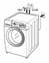
13 The air vent on the back of the machine must be left open and clear at all times. If the washer is installed in a closet or closed laundry alcove, there must be sufficient clearance and ventilation. The closet should have a full louvered door with at least 800 square inches (0.5 m 2 ) of open area for ventilation. The washer requires a space of at least 1 inch (2.5 cm) between the wall and the machine on each side and at least 4 inches (10 cm) between the back of the washer and the wall. Additional space may be needed for servicing. ACCESSORIES The washer comes with the two input hoses. The blue stripe is for cold water and the red stripe is for hot water. While the hoses are mechanically identical, it is critical to the performance of the washer to have the hot and cold hoses connected correctly. The wrench is used to remove (and replace) the shipping bolts and to adjust the leveling feet. Be sure to leave it and encourage the customer to retain the wrench, the four shipping bolts, and the manual in a safe place in the event the washer requires service or the customer moves. The shipping bolts MUST BE REMOVED before operating the washer. (See page 15.) Page 13 of 64 TRAINING MANUAL


14 REMOTE MONITOR and MODEM The remote laundry monitor (RLM) allows the user to monitor the progress of both washer and dryer, provided they are quipped with a modem. Remove the cover and install the modem on the back of the washer. Save the small socket cover and screws in the event you need to remove the modem for some reason. The socket should be covered at all times. Remove the cover and install the modem on the back of the dryer. Save the small socket cover and screws in the event you need to remove the modem for some reason. The socket should be covered at all times. After installation is complete, plug in the washer, dryer, and monitor, in that order. Turn on the washer and dryer. Press and hold the SET button on the monitor. Page 14 of 64 TRAINING MANUAL

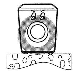
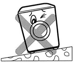
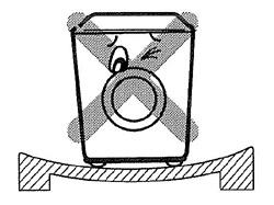
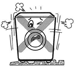
15 REMOVE THE SHIPPING BOLTS. INSTALLATION INSTALL THE WASHER ON A FIRM, FLAT SURFACE. ADJUST THE FEET TO BE LEVEL. Page 15 of 64 TRAINING MANUAL

16 CONNECTIONS WATER Be sure the rubber washer is inside the hose end. Attach the hoses to the washer (red is HOT, blue is COLD). Tighten them firmly but don t strip the plastic threads on the washer connections. DRAIN The drain pipe should be firmly attached to the standpipe or the laundry tub or sink where it drains. The pump has sufficient power to cause the pipe to move around when the water is expelled. The pump can lift the drain water a maximum of 96 inches (2.4 m), but there is no minimum height requirement. The vacuum breaker in the drain line will prevent drainage by gravity or siphoning. The hose can lay flat into a floor drain as long as the end of it is not submerged. ELECTRICAL The steam washer requires a 120 VAC, 60 Hz., dedicated, 20-amp circuit. Page 16 of 64 TRAINING MANUAL

17 CONTROL PANEL The control panel is locates on the front of the. All options are available from the control panel. Page 17 of 64 TRAINING MANUAL
18 OPTION BUTTONS PRE-WASH Press to add a pre-wash cycle. * Child Lock (Press and hold to select or deselect the Child Lock function) RINSE+SPIN *Drum Light EXTRA RINSE *Tub Clean STAIN CYCLE WATER PLUS *Language Press after power-up without selecting a cycle to rinse and spin ONLY, without washing! (Press and hold to turn the drum light on while the washer is operating.) Press to add an extra rinse cycle. (Press and hold to run a tub cleaning cycle. The washer must be empty!) Press to add additional washing time. Press to add extra water to the wash and rinse cycles. (Press this button with the washer OFF and then press POWER to access the language menu.) To select the optional feature, follow the instructions in parentheses. Page 18 of 64 TRAINING MANUAL

19 PROGRAM CHART This chart shows the components and their times of operation in the various wash cycles. The time estimates shown here are for the basic cycles before the fuzzy logic adjustments are made. BEFORE PERFORMING SERVICE Be careful to avoid electric shock when disconnecting parts for troubleshooting. Most terminals in the steam washer have 120 VAC or DC on them, sometimes even when the washer is off. The steam generator operates at a high temperature. Be careful when servicing it. It can be drained in place by removing the drain cap, but have a hose or a big towel ready to soak up the spillage. Page 19 of 64 TRAINING MANUAL


20 DISPENSER The dispenser drawer is a multi-chambered reservoir that allows the user to add all the appropriate laundry additives before starting the cycle. It has a place for pre-wash detergent, main wash detergent, fabric softener, and bleach. Powdered or liquid detergents may be used, but softener and bleach must be liquids. Detergents should carry the HE designation. Do not use regular detergents in the washer or oversudsing will occur. The top of the dispenser box is shown here. Page 20 of 64 TRAINING MANUAL

21 The dispenser works by using various solenoids to apply water to different compartments. The liquid products are dispensed from a siphon box. As the appropriate chamber is flooded, the box fills and the water flushes the laundry product into the tub. It is mixed with water before contacting the laundry to prevent spotting or damaging the fabric. Notice that the pre-wash and main wash fill tubes enter the dispenser at an angle. If one or the other fill valve is opened, the water goes into the appropriate detergent compartment. However, if they are opened simultaneously, the streams deflect and dispense the softener. Some water may run through the main and pre-wash compartments, but since the detergent has already been dispensed in an earlier part of the cycle, this is of no consequence. If liquid detergent is added to the pre-wash box, it will run immediately into the tub. This does not affect the operation of the cycle. To use liquid detergent in the main wash, place the detergent siphon box in the main wash compartment. Otherwise, the main wash liquid detergent will run into the tub along with the prewash detergent, causing oversudsing in the pre-wash and no cleaning in the main wash. The siphon boxes are designed to hold a liquid laundry product until the appropriate time for dispensing into the load. When the box fills with water, it begins to discharge its contents into the washer fill stream. Once the siphon action has started, it will continue until the siphon box has emptied itself. Use only regular viscosity bleaches and softeners; the ultra versions are usually much thicker and do not dispense well, if at all. By the end of any cycle, water will have run through all of the dispenser compartments, preventing any cross-contamination of subsequent loads. Page 21 of 64 TRAINING MANUAL


22 DIRECT DRIVE MOTOR The motor is a direct-drive, brushless, DC motor. It is attached to the drum via a splined shaft, eliminating belts, pulleys, transmissions, and the inherent problems associated with them. The rotor is attached to the shaft by one large bolt. The DC motor can be driven from stopped to maximum speed in infinite steps in either direction. There are 36 poles on the stator; 12 permanent magnets spaced around the rotor. There are no brushes to wear out. Unlike a more traditional brushless motor, the rotor surrounds the stator rather than being attached to it. A Hall Effect sensor determines the speed and direction of the motor. It also can read that the load is off balance when the drum speed fluctuates. Page 22 of 64 TRAINING MANUAL


23 HALL EFFECT SENSOR The Hall Effect sensor is easily removed and replaced. You ll have to remove the rotor and stator to access the sensor. When replacing the rotor, you ll probably need a helper to hold the drum in place when you push the rotor onto the shaft. Otherwise, the drum may move forward enough to make replacing the bolt difficult. The helper can also hold the drum from turning while you tighten the bolt. Before going to this trouble, check the connector on the main board. It is the red connector closest to the heat sink. Pull the connector off and verify the board is receiving a signal from the sensor. Page 23 of 64 TRAINING MANUAL

24 TEST MODE The steam washer must be empty and off to enter the test mode. 1. Press and hold SPIN SPEED and SOIL LEVEL. 2. Press POWER. 3. Press START/PAUSE to cycle through the test modes. (See chart.) CHECK THE WATER LEVEL FREQUENCY Page 24 of 64 TRAINING MANUAL

25 ERROR DISPLAY continued on next page Page 25 of 64 TRAINING MANUAL
26 Page 26 of 64 TRAINING MANUAL
27 DIAGNOSIS and CHECK LIST (Abnormal Operation) Page 27 of 64 TRAINING MANUAL
28 DIAGNOSIS and CHECK LIST (Abnormal Operation, continued) Page 28 of 64 TRAINING MANUAL
29 DIAGNOSIS and CHECK LIST (Abnormal Operation, continued) Page 29 of 64 TRAINING MANUAL
30 FAULT DIAGNOSIS and TROUBLESHOOTING Page 30 of 64 TRAINING MANUAL
31 DIAGNOSIS/TROUBLESHOOOTING (continued) Page 31 of 64 TRAINING MANUAL
32 DIAGNOSIS/TROUBLESHOOOTING (continued) Page 32 of 64 TRAINING MANUAL
 Page 33 of 64")
33 DIAGNOSIS/TROUBLESHOOOTING (continued) Page 33 of 64 TRAINING MANUAL
 Page 34 of 64")
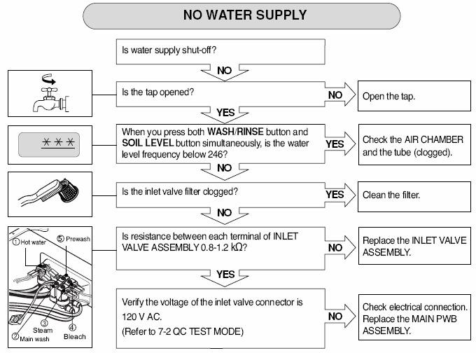
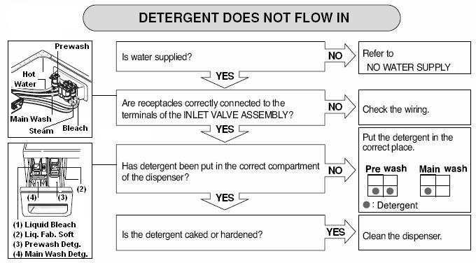
34 DIAGNOSIS/TROUBLESHOOOTING (continued) Page 34 of 64 TRAINING MANUAL
 Page 35 of 64")
35 DIAGNOSIS/TROUBLESHOOOTING (continued) Page 35 of 64 TRAINING MANUAL
36 DIAGNOSIS/TROUBLESHOOOTING (continued) Page 36 of 64 TRAINING MANUAL
 Page 37 of 64")
37 DIAGNOSIS/TROUBLESHOOOTING (continued) Page 37 of 64 TRAINING MANUAL
38 DISASSEMBLY and REPAIR The following pages will show the instructions for disassembly, repair, replacement of parts, and re-assembly. Many times, electrical components may be tested by connecting the appropriate meter to the leads or connectors on the main PC Board. (Refer to the block wiring diagram, below.) Proper diagnosis will eliminate unnecessary labor and expedite repairs. BLOCK WIRING DIAGRAM Page 38 of 64 TRAINING MANUAL


39 DISASSEMBLY/REPAIR (Control Panel) 1. Remove two screws on the back of the top plate. 2. Pull the top plate backward and lift, as shown. 3. Remove the detergent drawer. 4. Remove two screws behind the detergent drawer. 5. Disconnect the connector for the Display PWB. 6. Remove one screw from the corner of the control panel. 7. Lift the top away from the support rail and pull the control panel up and away to remove. 8. Remove eight screws to separate the control panel and PWB. 9. Reassembly is the reverse of these steps. Page 39 of 64 TRAINING MANUAL
 1. Disconnect the POWER connector and the Water Level Sensor Switch. 2. Remove the protective cover.")


40 DISASSEMBLY/REPAIR (Main Board) Often, you can diagnose a failed part by removing its connector on the main board and connecting the tester to the leads in the connector. (See page 54.) 1. Disconnect the POWER connector and the Water Level Sensor Switch. 2. Remove the protective cover. Press the plastic tabs out of the way to remove the cover. The main board is potted, so no repairs to it are possible. 3. Disconnect the connectors on the main board. They are all different, keyed, and colorcoded to prevent incorrect connection. 4. Pull the wires out of the way. 5. Remove one screw on the back of the washer to release the main board housing. 6. Remove the main board by sliding it to the right and lifting it up. Replacement is accomplished by pressing it toward the back of the washer and sliding it toward the left. Page 40 of 64 TRAINING MANUAL


 6. Remove two screws from the back of the cabinet DISASSEMBLY/REPAIR (Noise Filter) 1.")
41 DISASSEMBLY/REPAIR (Dispenser) 1. Remove the top plate. (See page 39.) 2. Remove the dispenser drawer. 3. Remove two screws to release the dispenser. 4. Loosen the clamp on the large hose that runs from the dispenser to the drum. Have an old towel handy to stuff under the dispenser to soak up any spillage. 5. Disconnect the connector from the solenoid. Make a note of the color codes and connections. #1 Blue; yellow and black wires #2 Red; violet and black wires #3 White; white and black wires #4 Blue; gray and black wires #5 Red; blue and black wires (hot) 6. Remove two screws from the back of the cabinet DISASSEMBLY/REPAIR (Noise Filter) 1. Remove the connectors from the noise filter. 2. Remove the screw from the top bracket. Page 41 of 64 TRAINING MANUAL


42 DISASSEMBLY/REPAIR (Front Cabinet Cover) 1. Remove the top plate. (See page 39.) 2. Remove the control panel. (See page 39.) 3. Remove four screws that secure the front panel. 4. Remove the screw that secures the filter cover. 5. Use a flat screwdriver or a putty knife to loosen the filter cover and pull it out. 6. Stick the screwdriver into the cover slot and pry it out sideways to free it. 7. Drain the sump by pulling out the little hose by the filter cover. Let the water (maybe as much as a quart) drain into a shallow pan. Don t pull the hose out so far you kink it or the water will not flow. Page 42 of 64 TRAINING MANUAL
 12.")
43 PRODUCT PARTS LIST DISASSEMBLY/REPAIR (Front Cabinet Cover, continued) 8. Open the door. 9. Remove the clamp using special tool 383EER4001A. 10. Lean the cabinet front forward, being careful to avoid breaking the glass. The door is HEAVY. 11. Disconnect the door switch connector. (Remember to replace it upon reassembly.) 12. Lift the door and front cover off the cabinet base as an assembly. Lay it face down on a blanket or some other protective surface. MODEL PRODUCT Page 43 of 64 TRAINING MANUAL
 1.")
44 DISASSEMBLY/REPAIR (Door) Removing the door with the front cover still on the machine. 1. Open the door. 2. Remove seven screws from the hinge cover. 3. Pry off the hinge cover with a flat screwdriver. 4. Remove the screw at the bottom of the hinge. 5. Lift the door off the hinge. CAUTION! The door is HEAVY! DISASSEMBLY/REPAIR (Door switch removal) 1. Open the door. 2. Remove the gasket clamp using special tool 383EER4001A. 3. Remove the two screws holding the switch. 4. Push the gasket aside to remove the switch. 5. Unplug the switch to change it. 6. Make sure the wires don t fall back in before you can replace the switch. Page 44 of 64 TRAINING MANUAL


45 DISASSEMBLY/REPAIR (Pump) 1. Remove the front cabinet. (See page 39.) 2. Drain the water from the sump. (See page 42.) 3. Remove the clamps and hoses. 4. Remove two screws and push the pump backward and up. 5. Press down the plastic tab on the base to slide the pump assembly backward. 6. You can tilt the pump in either direction to remove/replace the individual pumps without having to remove the tub. Have a towel handy to catch the spillage. Page 45 of 64 TRAINING MANUAL
 1.")
46 DISASSEMBLY/REPAIR (Heater) 1. Remove the front cabinet. (See page 39.) 2. Drain the water from the sump. (See page 42.) 3. Remove the push-on connectors from the heater. 4. Remove the nut that holds the ground wire. Then loosen but do not remove the nut that secures the heater clamp and pull the heater out. You may have to wiggle it to release the gasket. DISASSEMBLY/REPAIR (Thermistor) 1. Remove the front cabinet. (See page 39.) 2. Drain the water from the sump. (See page 42.) 3. Unplug the white connector. 4. Hold the bracket and pull the thermistor out. Page 46 of 64 TRAINING MANUAL
47 DISASSEMBLY/REPAIR (Object between tub and drum) 1. Remove the top cover. (See page 39.) 2. Remove the front cabinet cover. (See page 39.) 3. Remove the heater. (See page 46.) 4. Fish out the foreign object(s) using a wire or bar. DISASSEMBLY/REPAIR (Interior light) 1. Remove the top cover. (See page 39.) 2. Separate the connector near the lamp. 3. Remove the lamp assembly and lead wire from the gasket. 4. Replacement is the reverse of this procedure. Page 47 of 64 TRAINING MANUAL
 3. Pull the rotor off the shaft. 1. Remove two screws from the tub bracket. 2.")

48 DISASSEMBLY/REPAIR (Motor) For technical information concerning the direct drive DC motor, refer to page 22.) 1. Remove the back cover. 2. Remove the large bolt in the center shaft. (Your helper can hold the inside of the drum.) 3. Pull the rotor off the shaft. 1. Remove two screws from the tub bracket. 2. Remove six bolts on the stator. 3. Unplug two connectors on the stator. 4. Pull the stator off the shaft. 5. When re-installing, the clamps and the ground screw must be installed and the connectors pressed into place before the rotor is bolted onto the shaft. Page 48 of 64 TRAINING MANUAL
 2. Drain the water from the sump. (See page 42.) 3. Remove the control panel. (See page 39.) 4.")
49 DISASSEMBLY/REPAIR (Tub and Drum) Removing the tub/drum assembly is major surgery. It is much lighter if you remove the weights and the motor. Generally speaking, you ll have to remove all that anyway. 1. Remove the motor. (See page 48.) 2. Drain the water from the sump. (See page 42.) 3. Remove the control panel. (See page 39.) 4. Remove the front cabinet. (See page 39.) 5. Disconnect all hoses and electrical connections. 6. Separate the three dampers. (See page 50.) You can remove just one end now and the other one after the drum is out. 7. Pry apart the spring retainer clip. 8. Carefully lift the tub up off the springs and remove it from the machine. 9. Unbolt the bolts around the circumference of the seam. Separate the halves. Be careful to avoid damaging the gasket. Do not pry on the surfaces between the halves. Page 49 of 64 TRAINING MANUAL
 Be sure to press in the safety tab before pushing the pin out of the damper.")


50 DISASSEMBLY/REPAIR (Damper) 1. Disconnect the dampers from the tub and the base. (See photos, left.) Be sure to press in the safety tab before pushing the pin out of the damper. You can use a socket to hold the tab in while you squeeze the pin with the special tool 383EER4003A. 2. The flat end of the tool goes on the small end and the split end allows the head end to pass through while the pin is pushed out. The color and/or appearance of the damper may vary by model. 3. Use special tool 383EER4003A to remove the damper pins. If you are replacing the dampers, you ll have to remove both ends. If you are removing the tub for major repair work, disconnect the damper ends at the base and leave the other ends connected until you remove the tub. When putting the tub back into the machine, connect the dampers to the tub first. It is much easier that way. 4. Be careful not to pull the dampers apart while they are disconnected. Page 50 of 64 TRAINING MANUAL


51 DISASSEMBLY/REPAIR (Turbo Steam Generator) The TSG (Turbo Steam Generator) is supplied as an assembly only; parts like the sensor, thermistor, or heater cannot be replaced individually. Diagnosis is limited to determining malfunction and replacing as an assembly. The steam generator does not have to be removed from the machine to be drained. Be sure to let the water cool to avoid a burn. Have a hose available to slip onto the connector or a large towel to catch the water so it doesn t run down into the machine cabinet. If you remove the steam generator before draining it, be sure to avoid tipping it and spilling the water. 1. The steam generator can be removed as an assembly for diagnosis and replacement. 2. Unplug the washer. 3. Disconnect all electrical connections, including ground. 4. Drain the water. (You can drain the water later and it is easier.) 5. Remove all the cable straps by squeezing the tabs and pulling them out. They can be reused. 6. Remove the four screws holding the support rail in place and two screws attaching the steam generator. 7. Disconnect the hoses (water input and steam output.) 8. Push the steam generator toward the back of the washer to release it from the side rail. You can then remove it for draining, inspection, and replacement. It is sold as an assembly and is not repairable. Page 51 of 64 TRAINING MANUAL


52 1. When the TSG is installed in the washer, the hoses to the dispenser should fit into the tubing guides. 2. Be particularly careful when removing and replacing the water input hose to the steam generator. There is a check valve that fits into the input port. The valve sometimes comes off and is stuck in the hose. This could cause the water not to flow, which would cause the steam generator to malfunction. 3. Pull the check valve out of the hose gently and replace it into the water input port. Then slide the hose onto the port and install the clamp. Page 52 of 64 TRAINING MANUAL


53 TIPS and TRICKS HOSES When replacing the large hoses, be sure to avoid getting the lip turned under the hose clamp. This will damage the hose and cause a leak. The large hoses have notches on the ends to index them on the connectors. Be sure the notch is pushed down all the way on the index boss. BAFFLES You can replace the baffle and rollers without having to remove the drum. Unscrew the retaining screw at the back of the baffle. Slide it toward the front of the washer to remove it. You can unscrew the retainer inside the baffle to replace the roller balls. MUSHROOM VALVE Be sure the mushroom is in place before attaching the hose. If the stem is too long, it will contact the drum and make significant noise when the drum turns. BALL (Off Balance) SENSOR There isn t one. This function is handled by the microprocessor and the hall sensor. Page 53 of 64 TRAINING MANUAL
 1. NA, to display board 10. BL, fill valves 2. NA, to display board 11. BL, fill valves 3. RD, modem, display to control 12.")
54 MAIN BOARD The connector colors and functions are listed below as a guide. Remember, sometimes there may be a running production change. Refer to the wiring diagram. (NA = natural or cream, SB = sky blue, BL = blue, BK = black) 1. NA, to display board 10. BL, fill valves 2. NA, to display board 11. BL, fill valves 3. RD, modem, display to control 12. YL, steam level sensor 4. RD, lamp 13. BL, steam heater 5. NA, wash and steam thermistors 14. BK, wash heater 6. RD, motor control 15. YL, noise filter 7. NA, Hall effect sensor 16. WH, noise filter, ground 8. BL, pressure sensor 17. NA, modem, control to socket 9. NA, door lock 18. BL, LEDs (not on all models) Page 54 of 64 TRAINING MANUAL

55 WIRING DIAGRAM Page 55 of 64 TRAINING MANUAL
56 EXPLODED VIEW Cabinet and Control Panel Page 56 of 64 TRAINING MANUAL
57 EXPLODED VIEW Drum and Tub Assembly Page 57 of 64 TRAINING MANUAL
58 EXPLODED VIEW Dispenser Assembly Page 58 of 64 TRAINING MANUAL
59 Loc # Part No Description PARTS LIST 3829ER3041A Owner s Manual 3890EZ3612A Outer Box 3W20018B Wrench 3828ER3048Q Service Manual A ER0004P Cabinet Assembly A ER1028A Rear Cover A ER3001A Bushing A ER3001A Bushing A ER3014A Holder A FR3159E Shipping Bolt, Upper (Short) A FR3159D Shipping Bolt, Lower (Long) A ER1006C Top Plate Assembly A ER3021A Hinge A ER0039A Front Cabinet Cover A ER4005A Guide A133 2W20017E Gasket Clamp A ER2002A Hinge Assembly A ER4018A Guide A ER1012A Door Assembly A ER1037C Door Frame, Inner A ER1036A Door Frame, Outer A ER2006A Door Handle A ER4004A Door Latch Hook A FA3488M Hand Hold Cover A ER0001C Base Assembly A ER3006A Base Leg Bracket A ER3002A Leg Assembly A FD3715G Inlet Hose (Hot, Red) A FD3715H Inlet Hose (Cold, Blue) A ER2013B Case A ER3009A Drain Assembly A ER2008E Drain Cover A ER1006E Switch Assembly A ER1005K Power Cord Assembly A ER1004C Door Switch/Lock A ER1062D Main PCB Page 59 of 64 TRAINING MANUAL
60 Loc # Part No Description A ER1032A Main PCB Cover A EC1006B Line Noise Filter F ER2020B Display PCB F ER1044C Display Wiring Harness F ER2002B Flat Cable F ER1016F Wiring Harness F ER3003B Wiring Harness F FR2008F Inlet Valve, Cold (Quadruple) F FR2006H Inlet Valve, Hot (Single) F ER1279A Control Panel F ER3005A Control Knob F ER1274D Dispenser Drawer Assembly F ER3014B Siphon Cap, Softener F ER3018A Siphon Cap, Bleach F ER2003A Siphon Box, Detergent (Liquid) F ER1015B Dispenser Assembly F ER1004B Bellows F ER2002A Bellows F ER4001R Inlet Hose F ER4001J Inlet Hose F ER4002F Inlet Hose F ER4002F Inlet Hose F FR4006F Inlet Hose F FR4006R Connecting Hose F ER2002G Drain Hose Assembly F FR3156A Drain Hose Connector (Vacuum Break) F432 3W50712A Drain Hose Hanger F FD3663E Drain Hose, Vacuum Break to Drain F FR4125S Inlet Hose, Vacuum Break to Tub F FR4125S Hose, Vacuum Break F FR3188K Drain Hose, Pump to Vacuum Break F FR3068C Clamp F FR3068E Clamp F FR3068A Clamp F FR3092D Clamp F FR3092C Clamp F FR3092D Clamp F FR3068E Clamp F FR3092C Clamp F FR3068E Clamp Page 60 of 64 TRAINING MANUAL
61 Loc # Part No Description F560 Hose K ER0048B Outer Tub Assembly (Rear Half) K ER1017A Drum Assembly K ER1005A Baffle/Roller Assembly K ER0001A Spider (Drive Assembly) K FR4048N Ball Bearing K FR4048J Ball Bearing K FR4051C Main Bolt K ER2004A Main Bearing Seal K ER0007A Balance Weight, Lower K131 1SZZER4002A Screw, Custom for Weights K ER0004A Balance Weight, Upper K ER0026B Outer Tub Assembly (Front Half) K ER4001B Gasket K FA4353B Bolt, Standard K FR2046F Thermistor, NTC K FR4050A Gasket K FR1158J Heater Assembly K EA2001D Drain Pump Motor K FR4006L Recirculating Hose K ER1001A Pump Casing K EA2001C Recirculating Pump Motor K EER2001A Filter/Cover Assembly K FA1994G Stator Assembly K KW2002A Hall Effect Sensor Assembly K EA1002B Rotor Assembly K FR2084P Tub Support Spring K FR3040A Spring Holder K ER0004C Gasket K ER3007A Dual Nozzle K ER4001A Lamp K ER1002A Bellows K ER2001D Clamp Assembly Page 61 of 64 TRAINING MANUAL
62 K ER3002A Air Chamber K FR4125N Inlet Hose K EER3001J Damper Assembly K ER0001A Damper Pin M400 Turbo Steam Generator M ER1318A Support Rail 383EER4001A 383EER4003A 383EER4004A 5214FR3018D GASKET PLIER (SPECIAL TOOL) DAMPER PLIER (SPECIAL TOOL) GASKET PLIER (SPECIAL TOOL) DRAIN HOSE EXTENSION (5 FEET) Page 62 of 64 TRAINING MANUAL
63 (this page intentionally blank)
64 2006 LG Electronics, Inc. Printed in the USA
COMBO TRAINING. Washer/Dryer Combo WM3677HW WM3677HW
 COMBO TRAINING Washer/Dryer Combo Introduction Similarities and Differences While there are some similarities between regular (convection) dryers and the condenser dryer incorporated into the combo, many
 CONTENTS 1. Specifications... 2. Features and Technical Explanation... 2-1. Featurs... 2-2. Neuro fuzzy Washing time optimization... 2-3. Water level Contorl... 2-4. Door Contorl... 2-5. The door can cont
WASHER TRAINING WM2277. Rel WM2277 Washer Training
 WASHER TRAINING WM2277 1 Rel. 1.0 070813 SAFETY FIRST! Use the right tool for the job! 2 No Solicitation LG Electronics in no way supports, condones or will tolerate the solicitation of personnel while
SERVICE MANUAL WASHING MACHINE
 Website:http://www.LGEservice.com E-mail:http://www.LGEservice.com/techsup.html WASHING MACHINE SERVICE MANUAL! CAUTION READ THIS MANUAL CAREFULLY TO DIAGSE PROBLEMS CORRECTLY BEFORE SERVICING THE UNIT.
SERVICE MANUAL WASHING MACHINE MODEL: WM2496H*M CAUTION. Website: http: //www.lgeservice.com http: //www.lgeservice.com/techsup.
 Website: http: //www.lgeservice.com E-mail: http: //www.lgeservice.com/techsup.html WASHING MACHINE SERVICE MANUAL! CAUTION READ THIS MANUAL CAREFULLY TO DIAGSE PROEMS CORRECTLY BEFORE SERVICING THE UNIT.
WASHING MACHINE SERVICE MANUAL CAUTION READ THIS MANUAL CAREFULLY TO DIAGNOSE PROBLEMS CORRECTLY BEFORE SERVICING THE UNIT.
 WASHING MACHINE SERVICE MANUAL CAUTION READ THIS MANUAL CAREFULLY TO DIAGSE PROBLEMS CORRECTLY BEFORE SERVICING THE UNIT. MODEL : WM2240C* Jul. 2010 PRINTED IN KOREA P/No. : MFL30599179 CONTENTS 1.SPECIFICATIONS...
SERVICE MANUAL WASHING MACHINE MODEL: WM3431H*/WM3434H* WD-14312RD/WD-14316RD CAUTION
 Website: http://www.lgeservice.com [For U.S.A] www.lg.ca [For CANADA] E-mail: http://www.lgeservice.com/techsup.html WASHING MACHINE SERVICE MANUAL! CAUTION READ THIS MANUAL CAREFULLY TO DIAGSE PROBLEMS
SERVICE MANUAL WASHING MACHINE MODEL: WM2233H* / WM2233H*/01 CAUTION
 Website: http: //www.lgeservice.com E-mail: http: //www.lgeservice.com/techsup.html WASHING MACHINE SERVICE MANUAL! CAUTION READ THIS MANUAL CAREFULLY TO DIAGSE PROEMS CORRECTLY BEFORE SERVICING THE UNIT.
WASHING MACHINE READ THIS MANUAL CAREFULLY TO DIAGNOSE TROUBLE CORRECTLY BEFORE OFFERING SERVICE.
 website : http://www.lgeservice.com e-mail : http://lgeservice.com/techsup.html WASHING MACHINE SERVICE MANUAL CAUTION READ THIS MANUAL CAREFULLY TO DIAGSE TROUBLE CORRECTLY BEFORE OFFERING SERVICE. MODEL
DISCOVERY DRYER TRAINING MANUAL
 www.lgeservice.com DISCOVERY DRYER TRAINING MANUAL CAUTION! READ THIS MANUAL CAREFULLY BEFORE DIAGNOSING OR SERVICING THIS PRODUCT. Customer Service (and Part Sales) (800) 243-0000 Technical Support (and
WASHING MACHINE READ THIS MANUAL CAREFULLY TO DIAGNOSE TROUBLE CORRECTLY BEFORE OFFERING SERVICE.
 website : http://www.lgeservice.com e-mail : http://lgeservice.com/techsup.html WASHING MACHINE SERVICE MANUAL CAUTION READ THIS MANUAL CAREFULLY TO DIAGSE TROUBLE CORRECTLY BEFORE OFFERING SERVICE. MODEL
SERVICE MANUAL WASHING MACHINE MODEL: WM2277H*/WM2077CW/ WM2177H*/WM2677H*M CAUTION
 Website: http: //www.lgeservice.com E-mail: http: //www.lgeservice.com/techsup.html WASHING MACHINE SERVICE MANUAL! CAUTION READ THIS MANUAL CAREFULLY TO DIAGSE PROBLEMS CORRECTLY BEFORE SERVICING THE
SERVICE MANUAL WASHING MACHINE MODEL : WD-10120FD WD-12120(5)FD WD-14120(5)FD FWD-12120(5)FD FWD-14120(5)FD CAUTION
FD WD-14120(5)FD FWD-12120(5)FD FWD-14120(5)FD CAUTION") website : http://www.lgeservice.com e-mail : http://lgeservice.com/techsup.html WASHING MACHINE SERVICE MANUAL CAUTION READ THIS MANUAL CAREFULLY TO DIAGSE TROUBLE CORRECTLY BEFORE OFFERING SERVICE. MODEL
website : http://www.lgeservice.com e-mail : http://lgeservice.com/techsup.html WASHING MACHINE SERVICE MANUAL CAUTION READ THIS MANUAL CAREFULLY TO DIAGSE TROUBLE CORRECTLY BEFORE OFFERING SERVICE. MODEL
SERVICE MANUAL WASHING MACHINE FWD-12120(5)FD FWD-14120(5)FD FWD-16120(5)FD DWD-12120(5)FD DWD-14120(5)FD DWD-16120(5)FD
FD FWD-14120(5)FD FWD-16120(5)FD DWD-12120(5)FD DWD-14120(5)FD DWD-16120(5)FD") website : http://www.lgeservice.com e-mail : http://lgeservice.com/techsup.html WASHING MACHINE SERVICE MANUAL CAUTION READ THIS MANUAL CAREFULLY TO DIAGSE TROUBLE CORRECTLY BEFORE OFFERING SERVICE. MODEL
website : http://www.lgeservice.com e-mail : http://lgeservice.com/techsup.html WASHING MACHINE SERVICE MANUAL CAUTION READ THIS MANUAL CAREFULLY TO DIAGSE TROUBLE CORRECTLY BEFORE OFFERING SERVICE. MODEL
WASHING MACHINE READ THIS MANUAL CAREFULLY TO DIAGNOSE PROBLEMS CORRECTLY BEFORE SERVICING THE UNIT.
 Website:http://www.LGEservice.com E-mail:http://www.LGEservice.com/techsup.html WASHING MACHINE SERVICE MANUAL CAUTION READ THIS MANUAL CAREFULLY TO DIAGSE PROBLEMS CORRECTLY BEFORE SERVICING THE UNIT.
SERVICE MANUAL WASHING MACHINE MODEL : WD(M)-80150FB CAUTION. website :
-80150FB CAUTION. website :") website : http://www.lgeservice.com e-mail : http://lgeservice.com/techsup.html WASHING MACHINE SERVICE MANUAL CAUTION READ THIS MANUAL CAREFULLY TO DIAGSE TROUBLE CORRECTLY BEFORE OFFERING SERVICE. MODEL
website : http://www.lgeservice.com e-mail : http://lgeservice.com/techsup.html WASHING MACHINE SERVICE MANUAL CAUTION READ THIS MANUAL CAREFULLY TO DIAGSE TROUBLE CORRECTLY BEFORE OFFERING SERVICE. MODEL
SERVICE MANUAL WASHING MACHINE MODEL: WM2688H*M CAUTION. Website: http: // http: //
 Website: http: //www.lgeservice.com E-mail: http: //www.lgeservice.com/techsup.html WASHING MACHINE SERVICE MANUAL! CAUTION READ THIS MANUAL CAREFULLY TO DIAGSE PROEMS CORRECTLY BEFORE SERVICING THE UNIT.
WASHING MACHINE SERVICE MANUAL
 website : http://www.lgeservice.com e-mail : http://lgeservice.com/techsup.html WASHING MACHINE SERVICE MANUAL CAUTION READ THIS MANUAL CAREFULLY TO DIAGSE TROUBLE CORRECTLY BEFORE OFFERING SERVICE. MODEL
SERVICE MANUAL WASHING MACHINE MODEL : WD(M)-1018(0~9)S WD(M)-8018(0~9)N CAUTION
-1018(0~9)S WD(M)-8018(0~9)N CAUTION") website : http://www.lgeservice.com e-mail : http://lgeservice.com/techsup.html WASHING MACHINE SERVICE MANUAL CAUTION READ THIS MANUAL CAREFULLY TO DIAGSE TROUBLE CORRECTLY BEFORE OFFERING SERVICE. MODEL
website : http://www.lgeservice.com e-mail : http://lgeservice.com/techsup.html WASHING MACHINE SERVICE MANUAL CAUTION READ THIS MANUAL CAREFULLY TO DIAGSE TROUBLE CORRECTLY BEFORE OFFERING SERVICE. MODEL
WASHING MACHINE SERVICE MANUAL
 http://www.managemyhome.com WASHING MACHINE SERVICE MANUAL CAUTION READ THIS MANUAL CAREFULLY TO DIAGNOSE PROBLEMS CORRECTLY BEFORE SERVICING THE UNIT. MODEL : 796.4044#9## P/.: MFL30599145 CONTENTS 1.
WASHING MACHINE READ THIS MANUAL CAREFULLY TO DIAGNOSE TROUBLE CORRECTLY BEFORE OFFERING SERVICE.
 website : http://www.lgeservice.com e-mail : http://lgeservice.com/techsup.html WASHING MACHINE SERVICE MANUAL CAUTION READ THIS MANUAL CAREFULLY TO DIAGSE TROUBLE CORRECTLY BEFORE OFFERING SERVICE. MODEL
WASHING MACHINE SERVICE MANUAL
 Website:http://biz.lgservice.com WASHING MACHINE SERVICE MANUAL CAUTION READ THIS MANUAL CAREFULLY TO DIAGNOSE PROBLEMS CORRECTLY BEFORE SERVICING THE UNIT. MODEL : WM2701H* JAN. 2009 PRINTED IN KOREA
SERVICE MANUAL WASHING MACHINE MODEL : WD-3243RHD WD-3245RHD CAUTION. Website:http://www.LGEservice.com http://www.LGEservice.com/techsup.
 Website:http://www.LGEservice.com E-mail:http://www.LGEservice.com/techsup.html WASHING MACHINE SERVICE MANUAL CAUTION READ THIS MANUAL CAREFULLY TO DIAGSE TROUBLECORRECTLY BEFORE OFFERING SERVICE. MODEL
WASHING MACHINE SERVICE MANUAL
 Website:http://biz.lgservice.com WASHING MACHINE SERVICE MANUAL CAUTION READ THIS MANUAL CAREFULLY TO DIAGNOSE PROBLEMS CORRECTLY BEFORE SERVICING THE UNIT. MODEL: WM2801H*A MAY. 2008 PRINTED IN KOREA
SERVICE MANUAL WASHING MACHINE MODEL: WM2016CW CAUTION. Website: http: // http: //
 Website: http: //www.lgeservice.com E-mail: http: //www.lgeservice.com/techsup.html WASHING MACHINE SERVICE MANUAL! CAUTION READ THIS MANUAL CAREFULLY TO DIAGNOSE PROBLEMS CORRECTLY BEFORE SERVICING THE
WASHING MACHINE SERVICE MANUAL
 website : http://biz.lgservice.com e-mail : http://lgeservice.com/techsup.html WASHING MACHINE SERVICE MANUAL CAUTION READ THIS MANUAL CAREFULLY TO DIAGSE TROUBLE CORRECTLY BEFORE OFFERING SERVICE. MODEL
Fast Track Troubleshooting
 Fast Track Troubleshooting Model: WF210ANW/XAA Please Note: There are Serial # changes on this model, verify you are ordering the correct parts for the Serial # you are servicing by reviewing Bulletins.
Fast Track Troubleshooting
 Fast Track Troubleshooting Model: WF330ANW/XAA Please Note: There are two Versions of this model, when ordering parts please verify the version you are servicing. IMPORTANT SAFETY NOTICE For Technicians
WASHING MACHINE SERVICE MANUAL
 Website : http://biz.lgservice.com WASHING MACHINE SERVICE MANUAL CAUTION READ THIS MANUAL CAREFULLY TO DIAGNOSE PROBLEMS CORRECTLY BEFORE SERVICING THE UNIT. MODEL: WM3885H*CA / WM3875H*CA OCT. 009 PRINTED
TECHNICAL INFORMATION Touchtronic Clothes Dryers
 TECHNICAL INFORMATION Touchtronic Clothes Dryers Includes: T1302, T1303, T1322, T1329ci T1403 & T1405 2004 Miele This page intentionally left blank. Table of Contents GENERAL INFORMATION A. Warning and
G-7s. Instruction Manual. G-Series Cooler COUNTERTOP COOLER. Part No.11IPA
 G-Series Cooler COUNTERTOP COOLER Part No.11IPA-061000 Instruction Manual FOR YOUR FUTURE REFERENCE This easy-to-use manual will guide you in getting the best use of your cooler. Remember to record the
FOR SERVICE TECHNICIAN ONLY DO NOT REMOVE OR DESTROY WARNING
 WARNING Electrical Shock Hazard Disconnect power before servicing. Replace all parts and panels before operating. Failure to do so can result in injury or death. IMPORTANT Electric Discharge (ESD) Sensitive
SERVICE MANUAL WASHING MACHINE MODEL: WM2455H* / WM2301H* CAUTION. Website: http: // http: //
 Website: http: //www.lgeservice.com E-mail: http: //www.lgeservice.com/techsup.html WASHING MACHINE SERVICE MANUAL! CAUTION READ THIS MANUAL CAREFULLY TO DIAGNOSE PROBLEMS CORRECTLY BEFORE SERVICING THE
Installation Instructions. For the 18 Built-In Dishwasher and Front Color Panels
 Installation Instructions For the 18 Built-In Dishwasher and Front Color Panels Printed in USA 154232102 Before You Begin DO NOT INSTALL DISHWASHER UNTIL YOU HAVE READ ALL INSTRUCTIONS. FOR YOUR SAFETY,
WARNING. Electrical Shock Hazard FOR SERVICE TECHNICIAN ONLY DO NOT REMOVE OR DESTROY L WASHER. Pub # /18/10 GE
 L WASHER WARNING Electrical Shock Hazard Disconnect power before servicing. Replace all parts and panels before operating. Failure to do so can result in injury or death. IMPORTANT Electric Discharge (ESD)
TECH SHEET - DO NOT DISCARD PAGE
 TECH SHEET - DO NOT DISCARD PAGE 1 3. If this test mode has been entered successfully, all indicators on the console are illuminated for 5 seconds with 8:88 showing in the Estimated Time Remaining three-digit
Attached is Supplement three for service manual We suggest you file this with your Manual for reference.
 INTRODUCTION Attached is Supplement three for service manual 16008203. We suggest you file this with your 16008203 Manual for reference. Models covered in this manual: MAH21PD MAH21PN MAH21PR MAH21PS CONTENTS
Table of Contents. What to Expect with. Mounting Options. Tools Needed
 www.hunterfan.com Table of Contents What to Expect with Your Installation Congratulations on purchasing your new Hunter ceiling fan! It will provide comfort and performance in your home or office for many
Table of Contents What to Expect with Your Installation. Top Housing. Ceiling Plate. Tools Needed.
 Table of Contents Congratulations on purchasing your new Hunter ceiling fan! It will provide comfort and performance in your home or office for many years. This installation and operation manual contains
2. FEATURES & TECHNICAL EXPLANATION
 2. FEATURES & TECHNICAL EXPLANATION 2-1.FEATURES 40% Jumbo drum LG s jumbo drum can wash about 40% more per load than conventional washing machine. A bigger durm improves the wash performance. More economical
Quick Fix. Service Guide. Washers, Dryers, and Refrigerators
 Quick Fix Service Guide, Dryers, and Refrigerators Quick Fix tips provide a ready reference to the most frequently occurring repairs and adjustments that service technicians are likely to encounter. This
FOR SERVICE TECHNICIAN ONLY DO NOT REMOVE OR DESTROY
 L WASHER WARNING Electrical Shock Hazard Disconnect power before servicing. Replace all parts and panels before operating. Failure to do so can result in injury or death. IMPORTANT Electric Discharge (ESD)
SERVICE MANUAL WASHING MACHINE MODEL : GCW1069QS GCW1069CS CAUTION
 WASHING MACHINE SERVICE MANUAL CAUTION READ THIS MANUAL CAREFULLY TO DIAGNOSE PROBLEMS CORRECTLY BEFORE SERVICING THE UNIT. MODEL : GCW1069QS GCW1069CS MARCH. 2010 PRINTED IN KOREA P/No. : MFL30599165
Operator s Manual READY RACK EXTRACTOR. Installation/Operation/Maintenance/Parts DIMENSIONS OF THE WASHER: HEIGHT (AT BACK): 42
: 42") READY RACK EXTRACTOR DIMENSIONS OF THE WASHER: HEIGHT (AT BACK): 42 HEIGHT (W/ LID RAISED): 56 WIDTH: 27 DEPTH: 26 DEPTH (W/ REAR HOSE): 30 WEIGHT: 190 lbs. SHIP WEIGHT: 255 lbs. Operator s Manual Installation/Operation/Maintenance/Parts
READY RACK EXTRACTOR DIMENSIONS OF THE WASHER: HEIGHT (AT BACK): 42 HEIGHT (W/ LID RAISED): 56 WIDTH: 27 DEPTH: 26 DEPTH (W/ REAR HOSE): 30 WEIGHT: 190 lbs. SHIP WEIGHT: 255 lbs. Operator s Manual Installation/Operation/Maintenance/Parts
Installation Instructions
 Installation Instructions Before you begin... 2 Location... 2 Recommended grounding instructions... 2 Electrical requirements... 2 Exhaust requirements... 3 Water supply and drain requirements... 3 Please
Fast Track Troubleshooting
 Fast Track Troubleshooting Model: WF419AA*/XAA BOM Name: WF419AAW/XAA WF419AAU/XAA IMPORTANT SAFETY NOTICE For Technicians Only This service data sheet is intended for use by persons having electrical,
TOP AND CABINET PARTS
 TOP AND CABINET PARTS AUTOMATIC WASHER 7 06 Printed in U.S.A. (drd) 1 Part No. TOP AND CABINET PARTS 1 Literature Parts 8182751 Use & Care Guide 8182142 DVD Instruction 8182658 Quick Start Guide 8182208
TOP AND CABINET PARTS
 TOP AND CABINET PARTS AUTOMATIC WASHER 3 10 Printed in U.S.A. (drd) (psw) 1 Part No. Rev. A TOP AND CABINET PARTS 1 Literature Parts W10157503 Use & Care Guide W10177425 Tech Sheet W10157501 Energy Guide
Unpacking and removing shipping bolts. Connecting the drain line Leveling the washer Connecting to the power supply
 11 INSTALLATION Installation Overview Choosing the proper location Unpacking and removing shipping bolts Connecting the water line Connecting the drain line Leveling the washer Connecting to the power
TECHNICAL INFORMATION T1500 Series Clothes Dryers
 TECHNICAL INFORMATION T1500 Series Clothes Dryers 2003 Miele - Table of Contents 1.0 CONSTRUCTION & DESIGN 1.1 Appliance Overview - Vented 1 1.2 Appliance Overview Condenser Models 2 1.3 Controls Overview
Dacor Technical Service
 Attention: This manual is just a section from the complete Wall Oven Service Manual. If you find that you require the complete service manual, which includes exploded views and parts, use and care information
Please Keep This Manual For Future Reference REV.01
 ELCG347 ELCG240 1-855-571-1044 Please Keep This Manual For Future Reference REV.01 IMPORTANT INFORMATION When using electrical appliances, basic precautions should always be followed to reduce the risk
Fast Track Troubleshooting
 Fast Track Troubleshooting Model: WF409ANW/XAA Please Note: There are 2 versions of this model. Verify version # BEFORE ordering service parts. IMPORTANT SAFETY NOTICE For Technicians Only This service
SERVICE MANUAL ELECTRIC & GAS DRYER MODEL : DLE5911W DLE2511W DLE5932W DLE5932S DLE2532W DLE0332W
 Website:http://www.LGservice.com [For U.S.A] www.lg.ca [For Canada] ELECTRIC & GAS DRYER SERVICE MANUAL CAUTION READ THIS MANUAL CAREFULLY TO DIAGSE TROUBLES CORRECTLY BEFORE OFFERING SERVICE. MODEL :
Table of Contents What to Expect with. Tools Needed. Mounting Options. Wiring. Switch Housing.
 Table of Contents Congratulations on purchasing your new Hunter ceiling fan! It will provide comfort and performance in your home or office for many years. This installation and operation manual contains
MIRANDA F2 EXPLODED VIEW
 NO PART NAME QUANTITY 400 DETERGENT DRAWER COVER 40 CONTROL PANEL 402 PR. ADJUSTMENT KNOB GR (470+47) 403 PROGRAMME ADJUSTMENT SHAFT 405 LIGHT GUIDE DUO 406 BUTTON&LIGHTGUIDE BOX 4 PCB BOX 42 ELECTRONIC
TOP AND CABINET PARTS For Models: GHW9200LW0, GHW9200LQ0 (White/Grey) (White/Blue)
 (White/Blue)") TOP AND CABINET PARTS AUTOMATIC WASHER 11 02 Printed In U.S.A. (awm) 1 Part No. 8181891 Rev. A TOP AND CABINET PARTS 1 Literature Parts LIT8181894 Use & Care Guide LIT8181790 Tech Sheet LIT8181895 Energy
TOP AND CABINET PARTS AUTOMATIC WASHER 11 02 Printed In U.S.A. (awm) 1 Part No. 8181891 Rev. A TOP AND CABINET PARTS 1 Literature Parts LIT8181894 Use & Care Guide LIT8181790 Tech Sheet LIT8181895 Energy
Fast Track Troubleshooting
 Fast Track Troubleshooting Publication # rswf241 Revision Date 12/20/2011 Model: WF241ANW IMPORTANT SAFETY NOTICE For Technicians Only This service data sheet is intended for use by persons having electrical,
Service Manual for X9.5 and Older Models
 Service Manual for X9.5 and Older Models I. Common Issues... 2 A. Direct Air Motor... 2 A.1. Direct Air Motor will not run.... 2 A.2. Direct Air Motor is making a squealing sound.... 2 B. Full Bag Indicator
SERVICE MANUAL WASHING MACHINE MODEL : WD-14124(6)RD WD-12124(6)RD WD-10124(6)RD CAUTION
RD WD-12124(6)RD WD-10124(6)RD CAUTION") WASHING MACHINE SERVICE MANUAL CAUTION READ THIS MANUAL CAREFULLY TO DIAGSE TROUBLES CORRECTLY BEFORE OFFERING SERVICE. MODEL : WD-14124(6)RD WD-12124(6)RD WD-10124(6)RD CONTENTS 1. SPECIFICATION...3 2.
WASHING MACHINE SERVICE MANUAL CAUTION READ THIS MANUAL CAREFULLY TO DIAGSE TROUBLES CORRECTLY BEFORE OFFERING SERVICE. MODEL : WD-14124(6)RD WD-12124(6)RD WD-10124(6)RD CONTENTS 1. SPECIFICATION...3 2.
SERVICE MANUAL SPARE PARTS CATALOG AND EQUATOR COMBINATION WASHER-DRYER. First Edition - October Advanced Appliances.
 EQUATOR SERVICE MANUAL AND SPARE PARTS CATALOG First Edition - October 2003 COMBINATION WASHER-DRYER MODELS: EZ 1500 EZ 2500 C EZ 3600 C/CEE www.washerdryer.com Advanced Appliances Table Of Contents WARRANTY
SERVICE MANUAL WASHING MACHINE MODEL : WD-3274RHD / WD-3276RHD CAUTION
 Website:http://www.LGEservice.com [For U.S.A] www.lg.ca [For CANADA] E-mail:http://www.LGEservice.com/techsup.html WASHING MACHINE SERVICE MANUAL CAUTION READ THIS MANUAL CAREFULLY TO DIAGSE TROUBLECORRECTLY
XPS-ProDry User s Guide Dryer Base
 XPS-ProDry User s Guide XPS-ProDry User s Guide Dryer Base For Use with Inkjet Imaging Systems Manual Part#: M-3120 Revision: August 2005 XPS-ProDry User s Guide Written by Frank Mauri & John Brand Published
Manual is for the following models: G-26 GCG-26 GCG-26-C31N* G-26-C31N* GCG-26-C231N* GCG-26-CA31N* *G,I,M,7,J plug. Instruction Manual.
 G-Series Cooler G-26c/GCG-26c UPRIGHT COOLER Manual is for the following models: G-26 GCG-26 GCG-26-C31N* G-26-C31N* GCG-26-C231N* GCG-26-CA31N* *G,I,M,7,J plug Instruction Manual Manual is for the following
Homestyle Stacked Washer/Dryer
 Homestyle Stacked Washer/Dryer Parts Refer to Page 3 for Model Numbers SWD452C_802847 www.comlaundry.com Part No. 802847R8 August 2012 Table of Contents Title Page Parts Ordering Information... 2 Nameplate
It is essential to read this manual carefully before it is installed and used for the first time. EFL6KWH
 It is essential to read this manual carefully before it is installed and used for the first time. EFL6KWH This washing machine conforms to current safety requirements. Inappropriate use can, however, lead
Summer Breeze Heater Service Manual
 Summer Breeze Heater Service Manual RSBH RSBH-SB RSBHP Revision: 1.0 Issued: 12-18-2012 Table of Contents I. Basic Assembly and Operation A. Safety Instructions... 2 B. Grounding Instructions... 3 C.
Black 8KG 1400 Spin Speed Inverter Direct Drive Washing Machine Instruction Manual
 Black 8KG 1400 Spin Speed Inverter Direct Drive Washing Machine Instruction Manual Model number: RHWM81400DIDB Opening times: Monday - Friday 8am 6pm & Saturday 9am 1pm or visit us at Contents Safety Instructions
COMMERCIAL AUTOMATIC WASHER
 COMMERCIAL AUTOMATIC WASHER MODEL NO.(S) MHN30PDAWW0 10 10 Printed in U.S.A. (drd) (eeb) c 2010 WHIRLPOOL CORPORATION Part No. Rev. A TOP AND CABINET PARTS 2 TOP AND CABINET PARTS 1 Literature Parts W10353871
Dryer. User manual DV22K6800** DV22K A-00_EN (US)_ indd :15:41
_ indd :15:41") Dryer User manual DV22K6800** DV22K6800-03650A-00_EN (US)_151211.indd 1 2015-12-11 7:15:41 Before installation Read through the following instructions before installing the dryer, and keep this manual
Dryer User manual DV22K6800** DV22K6800-03650A-00_EN (US)_151211.indd 1 2015-12-11 7:15:41 Before installation Read through the following instructions before installing the dryer, and keep this manual
G-10s. Instruction Manual. G-Series Cooler UPRIGHT COOLER. Part No.11IPA
 G-Series Cooler UPRIGHT COOLER Part No.11IPA-062800 Instruction Manual FOR YOUR FUTURE REFERENCE Thank you for using our product. This manual will guide you in getting the best use of your cooler. Remember
GCG-9. Instruction Manual. G-Series Cooler. Manual is for the following models: GCG-9-N13EB G-9-N13EB GCG-9-B13EB UPRIGHT COOLER
 G-Series Cooler UPRIGHT COOLER Manual is for the following models: -N13EB G-9-N13EB -B13EB Instruction Manual FOR YOUR FUTURE REFERENCE This easy-to-use manual will guide you in getting the best use of
FATG OM 0604 OWNERS MANUAL. Anywhere. Everywhere. Fresh Air... To Go.
 62-000110-001 FATG OM 0604 Anywhere. Everywhere. Fresh Air... To Go. OWNERS MANUAL Contents Specifications...............................................2 Control Pad Layout..........................................2
Oreck Edge - Upright Tune-Up & Service Guide 02/26/2010
 The Oreck Manufacturing Company Oreck Edge - Upright Tune-Up & Service Guide 02/26/2010 Compiled by Clark DeNoble 1 Table of Contents Electrical Page 3 Tune-Up Evaluate Page 4 Clean Page 4 Replace Page
CONTENTS QUICK REFERENCE GUIDE PROGRAMME CHART
 1 CONTENTS Please read instruction for use QUICK REFERENCE GUIDE PREPARING THE LAUNDRY SELECTING A PROGRAMME AND OPTIONS STARTING AND COMPLETING A PROGRAMME CHANGING A PROGRAMME PROGRAMME CHART INTERRUPTING
Home Stacked Washer/Dryer
 Home Stacked Washer/Dryer Refer to Page 3 for Model Numbers Parts SWD443C_802107 www.comlaundry.com Part No. 802107R6 August 2014 Table of Contents Title Page Parts Ordering Information... 2 Serial Plate
WASHING MACHINE OWNER S MANUAL
 ENGLISH FRANÇAIS OWNER S MANUAL WASHING MACHINE Read this owner s manual thoroughly before operating the appliance and keep it handy for reference at all times WD100C* WD200C* MFL68267007 www.lg.com Copyright
L CABRIO TOP LOAD DIRECT DRIVE WASHER JOB AID W TECHNICAL EDUCATION WTW8500DW, WTW8500DC
 L-87 TECHNICAL EDUCATION 2014 CABRIO TOP LOAD DIRECT DRIVE WASHER WTW8500DW, WTW8500DC JOB AID W10758836 FORWARD This Whirlpool Job Aid, "2014 CABRIO Top Load Direct Drive Washer" (Part No. W10758836),
INDEX D1876 DISHWASHER (DW954)
") 2000-06 1 INDEX D1876 DISHWASHER (DW954) PROGRAMS 2 ELECTRICAL FUNCTIONS 5 PART NUMBER SUFFIX DEFINITIONS 7 SPARE PARTS LIST Casing and related parts 8 Container and related parts 10 Door 12 Control Panel
2000-06 1 INDEX D1876 DISHWASHER (DW954) PROGRAMS 2 ELECTRICAL FUNCTIONS 5 PART NUMBER SUFFIX DEFINITIONS 7 SPARE PARTS LIST Casing and related parts 8 Container and related parts 10 Door 12 Control Panel
TECHNICAL INFORMATION T 15xx Dryers
 TECHNICAL INFORMATION T 15xx Dryers 2010 Miele USA Table of Contents 1.0 2.0 3.0 T 15xx Dryers Construction and Design... 5 1.1 Appliance Overview Vented Models... 5 1.2 Appliance Overview Condenser Models...
GCG-10. Instruction Manual. G-Series Cooler. Manual is for the following models: GCG-10-N33EB G-10-N33EB UPRIGHT COOLER
 G-Series Cooler GCG-10 UPRIGHT COOLER Manual is for the following models: GCG-10-N33EB G-10-N33EB Instruction Manual Manual is for the following models: GCG-10-N33EB G-10-N33EB Instruction Manual GCG-10
Home Stack Washer/Dryers
 Home Stack Washer/Dryers Refer to Page 3 for Model Numbers Parts SWD456C_806093 www.alliancelaundry.com Part No. 806093R1 December 2016 Table of Contents Title Page Parts Ordering Information... 2 Serial
P MODEL AIR CONDITIONER
 CONSUMER SERVICES TECHNICAL EDUCATION GROUP PRESENTS R-94 P MODEL AIR CONDITIONER JOB AID Part No. 8178039 FORWARD This Whirlpool Job Aid, P Model Air Conditioner (Part No. 8178039), provides the technician
Homestyle Stack Washer/Dryers
 Homestyle Stack Washer/Dryers Refer to Page 3 for Model Numbers Parts SWD456C_806105 www.alliancelaundry.com Part No. 806105R1 November 2015 Table of Contents Title Page Parts Ordering Information...
! WARNING To avoid risk of electrical shock, personal injury or death; disconnect power before servicing, unless testing requires power.
 Top Load Washer Technical Information FAV6800A*, FAV7500A* Due to possibility of personal injury or property damage, always contact an authorized technician for servicing or repair of this unit. Refer
Marcone 2014 MSA Training. GE Mission 1 Top Load Washer
 Marcone 2014 MSA Training GE Mission 1 Top Load Washer 1 GE Mission 1 Top Load Laundry Mission One High Efficiency Top Load Washer/Dryer Launched industry-first features like integrated SmartDispense system
Nilfisk Inc Winnetka Avenue North Minneapolis, MN REV.03( ) VF80189
 VF80189") Nilfisk Inc. 9435 Winnetka Avenue North Minneapolis, MN 55445 www.usviper.com REV.03(05-) VF8089 SAFETY PRECAUTIONS This machine is intended for commercial use. It is constructed for use in an indoor
Nilfisk Inc. 9435 Winnetka Avenue North Minneapolis, MN 55445 www.usviper.com REV.03(05-) VF8089 SAFETY PRECAUTIONS This machine is intended for commercial use. It is constructed for use in an indoor
INSTALLATION INSTRUCTIONS UNDERCOUNTER DISHWASHERS
 INSTALLATION INSTRUCTIONS UNDERCOUNTER DISHWASHERS VIKING 111 Front Street Greenwood, Mississippi 38930 USA (662) 455-1200 IMPORTANT - PLEASE READ AND FOLLOW Before beginning - please read these instructions
WASHER/DRYER CONTROL PANEL PARTS
 WASHER/DRYER CONTROL PANEL PARTS WASHER/DRYER LAUNDRY SYSTEM 1 Literature Parts W10356098 Installation Instructions W10343071 Guide, Use & Care W10364010 Wiring Diagram W10343084 Energy Guide 2 3390688
INSTALLATION INSTRUCTIONS
 INSTALLATION INSTRUCTIONS INSTALLATION REQUIREMENTS Tools and Parts Gather required tools and parts before starting installation. Tools needed: Optional tools: Flashlight Options: Bucket Pedestal: You
COMMERCIAL STACKED GAS DRYER/WASHER
 COMMERCIAL STACKED GAS DRYER/WASHER MODEL NO. CGT8000XQ0 c 2012 WHIRLPOOL CORPORATION 5 12 Litho In U.S.A. (CMS) (bay) Part No. Rev. H CONTROL PANEL PARTS 2 CONTROL PANEL PARTS 1 Literature Parts W10335467
Homestyle Stacked Washer/Dryer
 Homestyle Stacked Washer/Dryer Parts Refer to Page 3 for Model Numbers SWD443C_801802 www.alliancelaundry.com Part No. 801802R8 January 2018 Table of Contents Title Page Parts Ordering Information...
Full Size Canister Service Manual Riccar Models 1700 / 1800 Power Nozzles RPB-100 / RPB-220 / RPB-224 / RPB-250
 Full Size Canister Service Manual Riccar Models 1700 / 1800 Power Nozzles RPB-100 / RPB-220 / RPB-224 / RPB-250 Table of Contents I. General Full Size Canister Issues...2 A. Full Bag Indicator...2 1. General
Please read this manual before using the machine. Please keep this manual within easy reach for quick reference.
 INSTRUCTION MANUAL Please read this manual before using the machine. Please keep this manual within easy reach for quick reference. HIGH SPEED SINGLE NEEDLE STRAIGHT LOCK STITCHER Thank you very much for
TOP AND CABINET PARTS
 TOP AND CABINET PARTS AUTOMATIC WASHER 12 08 Printed in U.S.A. (drd)(bay) 1 Part No. Rev. A TOP AND CABINET PARTS 1 Literature Parts W10151563 Use & Care Guide W10207733 Tech Sheet W10171153 Energy Guide
PWC-500/1000/1010/1500
 SERVICE MANUAL for by Vertex Model PWC-500/1000/1010/1500 P/N man-7008 Table of Contents 1. Introduction 2. Cooler Set-up 3. Remove Top Cover 4. Remove/Replace Float 5. Remove/Replace Hot Tank 6. Faucet
TECH SHEET DO NOT DISCARD PAGE 1. If unsuccessful entry into diagnostic mode, actions can be taken for specific indications:
 TECH SHEET DO NOT DISCARD PAGE 1 WARNING Electrical Shock Hazard Disconnect power before servicing. Replace all parts and panels before operating. Failure to do so can result in death or electrical shock.
SERVICE MANUAL. Kleenmaid SMART oven OMFHS6010
 SERVICE MANUAL Kleenmaid SMART oven OMFHS6010 2 Contents 1. Product identification 4 2. DEMO mode (showroom operation) 5 3. Child Lock 6 4. Automatic power cut-off 7 5. Error Codes 8 6. Door assembly 9
Installation Instructions
 Instructions for Frontload Washers Original Instructions Keep These Instructions for Future Reference. (If this machine changes ownership, this manual must accompany machine.) www.alliancelaundry.com Part
! WARNING To avoid risk of electrical shock, personal injury or death; disconnect power to washer before servicing, unless testing requires power.
 27 Front Load Washer - Technical Information MAH6700A* Due to possibility of personal injury or property damage, always contact an authorized technician for servicing or repair of this unit. Refer to Service