SUMMARY. Page 12. Selecting an immersion heater. Page 42. Junction boxes for immersion heaters. Page 59. Page 73. Page 79
|
|
|
- Berniece Davis
- 5 years ago
- Views:
Transcription


1 SUMMARY Page 6 Page 7 Page 12 Page 15 Page 32 Atex marking Heating elements Selecting an immersion heater Screw plug immersion heaters Flange immersion heaters Page 40 Page 41 Page 42 Page 44 Page 47 Clamp flange immersion heaters Ceramic core elements Junction boxes for immersion heaters Control thermostats for immersion heaters Atex screw plug and flange immersion heaters Page 56 Page 57 Page 59 Page 60 Page 62 Accessories for immersion heaters Removable immersion heaters Drum heaters Fluorated immersion heaters Fluid circulation heaters Page 68 Page 71 Page 73 Page 74 Page 75 Heating hoses Finned strip heaters Anti-condensation cabinet heaters Radiators Atex radiators Page 76 Page 78 Page 79 Page 80 Page 85 Fan heaters and convectors Hot air generators Circular air duct heaters Rectangular and flange air duct heaters Cartridges Vulstar Indicates the presence of ATEX certified products in the chapter 4


2 SUMMARY Page 89 Page 90 Page 91 Page 92 Page 94 Accessories for Vulstar Sheathed mica ring and strip heaters PTC resistors Band heaters Heat tracing Page 97 Page 100 Page 102 Page 107 Page 111 Accessories for heat tracing Silicone heating panels Infrared generators Control thermostats and safety temperature cut out Electromechanical thermostats Page 112 Page 114 Page 119 Page 122 Page 123 Selecting a temperature sensor PT 100 sensors Thermocouples Accessories for temperature sensors Converters Page 124 Page 126 Page 128 Page 130 Page 132 Sealing glands Temperature displays and controllers Static power units Cabinets Isolators and wires for cabeling Page 134 Page 141 Page 146 Page 146 Page 147 Temperature control units Vulcatherm Water Temperature control units Vulcatherm Thermal Oil Air conditioning units Liquid chillers Dehumidifiers Edenair Indicates the presence of ATEX certified products in the chapter 5
3 ATEX MARKING 0080 II 2 G Ex d IIC T4 Gb Equipment that complies with European directives Explosive environment Device category Eletric equipment N of the notified body Place of installation Flammable substance Protection mode Dust and gas group Temperature class T1 up to T6 or xxx C Equipment protection level (EPL) N of the notified body Protection mode d Explosion-proof Prevent the transmission of the explosion to the environment 0081 France LCIE 0080 France INERIS 0102 Germany IBExU 0722 Spain LOM e Increased safety Prevent excessive temperature and sparks from electrical equipement de Explosion-proof and increased safety Prevent both transmission of the explosion and electric spark Place of installation I = Mines II = Ground ia Intrinsic safety Limited electrical energy below the level of self ignition Dust and gas group Gas group Place of installation Typical gas Energy of self ignition I Mines Methane E 300 µj IIA Propane, butane, benzene, acetone, alcoholl, kerosene, Gasoline, Petrol E 240 µj Device category IIB Ground Ethylene, diethyl ether E 70 µj IIC Hydrogen, acetylene E 17 µj Zones 0 Zones 20 Zones 1 Zones 21 Zones 2 Zones 22 Gas Dust Gas Dust Gas Dust Risk of explosion HIGH MEDIUM LOW Continuously present Often present Accidentally present Time > 1000 Hours / year 10 < Hours / year < 1000 < 10 Hours / year Dust group IIIA IIIB IIIC Temperature class Temperature class Place of installation Hazard Size Resistivity Ground T6 85 C T5 100 C Combustible flyings None-conductive dust Conductive dust T4 135 C T3 200 C Ø 0,5 mm Ø < 0,5 mm Ø < 0,5 mm T2 300 C R > 1000Ωm R < 1000Ωm T1 450 C Setting of safety devices 80 C 95 C 130 C 190 C 290 C 440 C Flammable substance G = Gas D = Dust Temperature Class for gas Carbone disulfide (95 C) T6 Diethyl ether (160 C) T4 Kerozene (210 C) T3 Acetylene (305 C) T2 Ethylene (425 C) T2 Methane (537 C) T1 Hydrogen (560 C) T1 Equipment protection level (EPL) Group II - Gas area Group II - Dust area Category Zone EPL Catégory Zone EPL II 1 G 0 Ga II 1 D 20 Da II 2 G 1 Gb II 2 D 21 Db II 3 G 2 Gc II 3 D 22 Dc 6 vulcanic.com
4 HEATING ELEMENTS Applications : Tubular sheathed elementsn are quasi universal solution used to heat up solids, liquids or gas through the JOULE EFFECT up to about 800 C. Depending on their use, they transfer their energy by natural or forced convection, by conduction or induction. SEALING WP+: Waterproof resin sealing.the most standard one. Excellent sealing that guarantees insulation in case of prolonged storage or application in moisture conditions. Maximum admitted connection temperature of 160 C. TM : Silicon cost effective solution operational up to a connection temperature of 350 C in environnement exempt from moisture. HT : Ciment high temperature, no water-tight sealing,operational up to a connection temperature of 450 C. Using in atmospheres without moisture. TUBE Ø 6,5-6, ,5 10, (mm) LENGTH up to 6 m SURFACE LOAD up to 20 W/cm 2 VOLTAGE up to 750 V CONNECTIONS Threaded terminals M4 or M6 for Ø8 M5 for Ø8,5 M5 or M6 for Ø10,2 M6 for Ø16 Spade terminal Clamping screw Copper lead Nickel lead FASTENINGS Three-piece union Crimped threaded union Brazed threaded union Welded threaded union Hooks MATERIALS SURFACE LOAD APPLICATION Carbon steel 2 W/cm 2 Oil, fuel oil, heat transfer fluid AISI 321/Din W/cm 2 Air, gas, solids Carbon steel 4 W/cm 2 Circulating light oil AISI 321/Din W/cm 2 Air, circulating fluids, solids AISI 316L/Din W/cm 2 Process heating water Incoloy 800/Din W/cm 2 Air, gas, solids Incoloy 825/Din W/cm 2 Sanitary water Copper 10 W/cm 2 Circulating fresh water AISI 904L/Din W/cm 2 Circulating water BENT TO SHAPE Tubular heating elements can be shaped to suit your requirements. We can manufacture and deliver special elements quickly and cost-effectively. DETERMINATION OF REQUIRED POWER To heat a volume V (solid, liquid or gas) in a given time T (without state modification). T = H2 - H1 H1 Heating time H2 Vaporization of a mass M (liquid) in a given time T when the liquid is already at its boiling temperature. T = H2 - H1 H1 H2 Heating time t1 t2 V ( C) V ( C) V V Units to be known V : Volume in liter or dm3 ρ Cp L Units to be known ρ : Density en kg/dm3 Carbon steel 7,8 0,12 M : Weight of the liquid in kg. V x ρ : Mass to be heated in kg Stainless steel 7,8 0,12 L : Latent heat of vaporization in kcal/kg t1 : Initial temperature in C Water T : Heating time in hour. t2 : Final temperature in C Oil 0,9 0,5 Cp : Specific heat kcal/kg. C Air 0,0013 0,25 T : Heating time in hours. Result : P = Power to be installed in kw 1,2 : safety factor taking into account the tolerances on voltage Result : P = Power to be installed in kw supply and ohmic value of the heating element. 1,2 : safety factor taking into account the tolerances on voltage supply and ohmic value of the heating element. V x ρx Cp x (t2 - t1) x 1,2 P = M x L x 1,2 P = 860 x T 860 x T 7
5 HEATING ELEMENTS STANDARD STRAIGHT TUBULAR HEATING ELEMENTS Insulating part O Sealing Threaded terminal Connection by M6 threaded steel rod. The elements are annealed, so that they can be bent them to shape. N VVV VVV = HL = L Ø8 : N=30 - Ø10,2 : N = 32 - Ø16 : N = 38 N HL = heating length Ø 8 mm in AISI 321/Din Wcm 2 TM seals Power Voltage L HL Weight +5-10% 1P (mm) (mm) (kg) W 230 V , W 230 V , W 230 V , W 230 V , W 230 V ,0 Ø 10,2 mm in AISI 321/Din W/cm 2 TM seals Power Voltage L HL Weight +5-10% 1P (mm) (mm) (kg) W 230 V , W 230 V , W 230 V , W 230 V , W 230 V , W 230 V ,8 Ø 10,2 mm in VLY/AISI 904L/Din W/cm 2 WP+ seals Power Voltage L HL Weight +5-10% 1P (mm) (mm) (kg) W 230 V , W 230 V , W 230 V , W 230 V , W 230 V , W 230 V , W 230 V ,9 Ø 16 mm in AISI 321/Din W/cm 2 TM seals Power Voltage L HL Weight +5-10% 1P (mm) (mm) (kg) W 230 V , W 230 V , W 230 V , W 230 V , W 230 V , W 230 V , W 230 V ,5 B Ø 8mm in Incoloy 800/Din W/cm 2 - TM seals W 400 V ,3 Ø 10,2 mm in VLY/AISI 904L/Din W/cm 2 - TM seals Power Voltage L HL Weight +5-10% 1P (mm) (mm) (kg) Power Voltage L HL Weight +5-10% 1P (mm) (mm) (kg) W 230 V , W 230 V , W 230 V , W 230 V , W 230 V , W 400 V , W 230 V , W 230 V , W 230 V , W 230 V , W 230 V ,9 Ø 10,2mm in Incoloy 800/Din W/cm 2 TM seals Power Voltage L HL Weight +5-10% 1P (mm) (mm) (kg) W 230 V , W 230 V , W 230 V , W 230 V , W 230 V , W 400 V , W 400 V , W 400 V ,0 Ø 16 mm in AISI 321/Din W/cm 2 TM seals Power Voltage L HL Weight +5-10% 1P (mm) (mm) (kg) W 230 V , W 230 V , W 230 V , W 230 V , W 400 V , W 400 V , W 400 V ,0 Examples of shaped heating elements B B B B Ø 8 mm in AISI 321/Din W/cm 2 WP+ seals Power Voltage L HL Weight +5-10% 1P (mm) (mm) (kg) W 230 V , W 230 V , W 230 V , W 230 V , W 230 V ,1 Ø 10,2 mm in AISI 321/Din W/cm 2 TM seals Power Voltage L HL Weight No % 1P (mm) (mm) (kg) W 230 V , W 230 V , W 230 V , W 230 V , W 230 V , W 400 V ,8 Ø 10,2 mm in VLY/AISI 904L/Din W/cm 2 - WP+ seals W 400 V ,2 Ø 16mm in Incoloy 800/Din W/cm 2 TM seals Power Voltage L HL Weight +5-10% 1P (mm) (mm) (kg) Power Voltage L HL Weight +5-10% 1P (mm) (mm) (kg) W 230 V , W 230 V , W 230 V , W 230 V , W 230 V , W 230 V , W 400 V , W 400 V , W 400 V , W 230 V , W 230 V , W 230 V , W 230 V , W 230 V , W 400 V , W 400 V , W 400 V , W 400 V , W 400 V ,5 O1 n bends 40 L L M M M L L M C C C C C C C2 C1 8
6 C U-SHAPED TUBULAR HEATING ELEMENTS VVV VVV HL N L Ø 8 : N=30 - Ø 10,2 : N=32 - Ø 16 : N=38 HL = heating length Ø 8 mm in Incoloy 800 / Din W/cm 2 WP+, C = 30 Power Voltage L HL Weight +5-10% 1P (mm) (mm) (kg) W 230 V , W 230 V , W 230 V , W 230 V , W 230 V , W 400 V , W 400 V , W 400 V Ø 10,2 mm in AISI 321/Din W/cm 2, TM, C = 29 Power Voltage L HL Weight +5-10% 1P (mm) (mm) (kg) W 230 V , W 230 V , W 230 V , W 230 V , W 230 V , W 230 V ,8 Ø 10,2 mm in Incoloy 800 / Din W/cm 2, WP+, C = 45 Power Voltage L HL Weight +5-10% 1P (mm) (mm) (kg) W 230 V , W 230 V , W 230 V , W 230 V , W 230 V W 400 V , W 400 V , W 400 V Ø 10,2 mm in AISI 904L / Din W/cm 2, WP+, C = 45 Power Voltage L HL Weight +5-10% 1P (mm) (mm) (kg) W 230 V , W 230 V , W 230 V , W 400 V , W 400 V , W 400 V ,6 Ø HEATING ELEMENTS Electrical connections with steel threaded terminals M6 On request Connection by carbon steel crimped threaded rod : order xx514 instead of xx504. Ø 8 mm in AISI 316L / Din SP* - 6 W/cm 2, WP+, C = 25 Power Voltage L HL Weight +5-10% 1P (mm) (mm) (kg) W 230 V , W 230 V , W 230 V , W 230 V , W 230 V , W 400 V W 400 V ,3 Ø 10,2 mm in AISI 904L / Din W/cm 2, WP+, C = 45 Power Voltage L HL Weight +5-10% 1P (mm) (mm) (kg) W 230 V , W 230 V , W 230 V , W 230 V , W 230 V ,8 Ø 10,2 mm in AISI 316L/Din SP* - 6 W/cm 2, WP+, C=29 Ø 10,2 mm in Incoloy 800 / Din W/cm 2 WP+, C = 45 Power Voltage L HL Weight Power Voltage L HL Weight +5-10% 1P (mm) (mm) (kg) +5-10% 1P (mm) (mm) (kg) W 230 V , W 230 V , W 230 V , W 230 V , W 230 V W 400 V , W 400 V , W 400 V Ø 10,2 mm in AISI 904L / Din W/cm 2, WP+, C = 45 Power Voltage L HL Weight +5-10% 1P (mm) (mm) (kg) W 230 V , W 230 V , W 230 V , W 230 V , W 230 V , W 230 V ,6 Ø 8 mm in AISI 312 / Din W/cm 2, TM, C = 25 Power Voltage L HL Weight +5-10% 1P (mm) (mm) (kg) W 230 V , W 230 V , W 230 V , W 230 V , W 230 V Ø 8 mm in Incoloy 800 / Din W/cm 2, WP+, C = 30 Power Voltage L HL Weight +5-10% 1P (mm) (mm) (kg) W 230 V , W 230 V , W 230 V , W 230 V , W 230 V , W 400 V W 400 V ,3 Ø 10,2 mm in AISI 904L / Din W/cm 2, WP+, C = 45 Power Voltage L HL Weight +5-10% 1P (mm) (mm) (kg) W 230 V , W 230 V , W 230 V , W 230 V , W 230 V , W 230 V , W 230 V , W 230 V , W 230 V , W 230 V , W 230 V , W 230 V , W 400 V , W 400 V W 400 V , W 400 V ,8 Ø 16 mm in AISI 321/Din W/cm 2, TM, C = 45 Power Voltage L HL Weight +5-10% 1P (mm) (mm) (kg) W 230 V , W 230 V , W 230 V , W 230 V , W 230 V , W 230 V , W 230 V ,5 Ø 16 mm in AISI 316L/Din SP* - 6 W/cm 2, WP+, C = 45 Power Voltage L HL Weight +5-10% 1P (mm) (mm) (kg) W 230 V , W 230 V , W 230 V , W 230 V , W 230 V , W 400 V , W 400 V , W 400 V , W 400 V , W 400 V ,5 Ø 16 mm in Incoloy 800 / Din W/cm 2, WP+, C = 65 Power Voltage L HL Weight +5-10% 1P (mm) (mm) (kg) W 230 V , W 230 V , W 230 V , W 230 V , W 230 V , W 400 V , W 400 V , W 400 V , W 400 V , W 400 V ,5 Ø 16 mm in Incoloy 800 / Din W/cm 2, WP+, C = 65 Power Voltage L HL Weight +5-10% 1P (mm) (mm) (kg) W 230 V , W 230 V , W 230 V , W 230 V , W 400 V , W 400 V , W 400 V , W 400 V , W 400 V , W 400 V ,6 * SP = scoured and passivated 9
 (mm) (mm) (mm) pack (kg) 55144-04 6.5/6.")

7 HEATING ELEMENTS FIXING ACCESSORIES Threaded nipples allow a watertight fixing of tube 26501and Supplied with nut and gasket. Max. pressure : 10 bar Ø M C hexagonal P on flats 25 maxi 4 F 2 5 Tube Ø Ø M C P F in Weight (mm) (mm) (mm) (mm) pack (kg) / x 1, , x 1, , x 1,5 25, , x 1,5 31, , x 1, ,52 Inside Ø of fixing = Ø Tube Fixing brackets in chrome-plated steel: These brackets allow elements to be fixed to flat or slightly convex surfaces and permit expansion. Ø A B 11 Ø Tube Ø A B in Weight (mm) (mm) (mm) pack (kg) / , / , , , , , , ,50 HEATING ELEMENTS FOR INDUSTRIAL OVENS Heat-resistant stainless steel sheathed elements for industrial ovens and drying cabinets up to 300 C. Heating by natural convection (air) or radiation (solids). Supply voltage: 230V single phase. Connection by M6 threaded terminals and M6 ground terminal. 42 M6 100 B 245 Power A B C Weight +5-10% (mm) (mm) (mm) (kg) W , W , W ,220 TUBULAR ELEMENTS FOR HOTPLATES C A Stainless-steel sheathed element in a flat circular shape to heat solids up to 300 C by conduction (2 heating stages from 1000W upwards). Supply voltage : 230V single phase. Connection by flat terminals with calliper. Accessories : Clips for models (Weight 0,040 kg) holes, 86 mm between centres holes, 138 mm between centres H Ø Ø 124 Power Ø H Weight Fig % (mm) (mm) (kg) W ,160 A W ,400 B W ,600 B W ,700 B SQUARE-SECTION HEATING ELEMENTS Especially suited to heat flat and cylindrical surfaces, their square cross-section allows a large area of contact with the object to be heated. This enables large transfers of heat and high temperatures (max. 700 C on the heating element). Sheathed elements are available either straight or shaped to your requirements (minimum bend radius = 19 mm) Tubes of 5x5 or 7,1x7,1 section are in stainless steel. Connection at one end by 60cm cable with earth wire protected by metal braid. HT seals. The heating element is retained in a groove. HL L Metallic braid 15mm maxi. Ø 12mm maxi HL = heating length Power Voltage Section L HL +5-10%single phase (mm) (mm) (mm) W 230 V 5X W 230 V 5X W 230 V 7,1X7, W 230 V 7,1X7, W 230 V 7,1X7, W 230 V 7,1X7, W 230 V 7,1X7, Load 2 W/cm 2 Load 4 W/cm 2 Load 6 W/cm 2 Website : Power Voltage Section L HL +5-10%single phase (mm) (mm) (mm) W 230 V 5x W 230 V 5x W 230 V 5x W 230 V 5x W 230 V 7,1x7, W 230 V 7,1x7, W 230 V 7,1x7, W 230 V 7,1x7, W 230 V 7,1x7, W 230 V 7,1x7, W 230 V 7,1x7, catalogue-vulcanic@vulcanic.com Power Voltage Section L HL +5-10%single phase (mm) (mm) (mm) W 230 V 5x W 230 V 5x W 230 V 5x W 230 V 7,1x7, W 230 V 7,1x7, W 230 V 7,1x7, W 230 V 7,1x7, W 230 V 7,1x7, W 230 V 7,1x7, W 230 V 7,1x7,


8 FLUIDS HEATING Screw plug immersion heaters VULCALOY flange immersion heaters Flange immersion heaters Clamp flange immersion heaters Ceramic core elements ATEX screw plug and flange immersion heaters Removable immersion heaters Drum heaters Fluorated tank bottom heaters Fluid circulation heaters Heating hoses 11
 or forced convection (fluids in circulation).")

 Insulation Mounting interface Thickness With or without control With or without safety probes? Power requirements?")
 Specific load Liquid (Static) Specific load Water See table page 13 10 W/cm 2 Max Oil 2 W/cm 2 Max Other liquids contact us.")
 + Pth (thermal losses) = P total power requirements (kw) Power requirements?")
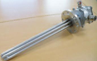
9 SELECTING AN IMMERSION HEATER APPLICATION : Electric immersion heaters are suited to heat up fluids (liquids and gas) by natural (static fluids) or forced convection (fluids in circulation). They are designed to heat up trough heating elements (pins, monotubes or ceramic cores) in direct contact with the fluid to be heated. Heating elements layout enables the optimization of heat transfers. R EQUIREMENTS: Immersion heater requirements? Type of fluid? Volume of liquid to be heated? Start temperature (before heating) (t 1 )? Target temperature. (t 2 )? Heating time? Pressure? Available space (Internal and external) Insulation Mounting interface Thickness With or without control With or without safety probes? Power requirements? t 1 Required temperature Time required for heating t 2 S OLUTIONS : Suitable materials (Heating elements, flanges...) Specific load Liquid (Static) Specific load Water See table page W/cm 2 Max Oil 2 W/cm 2 Max Other liquids contact us. Power of the immersion heater Type of immersion heater Pressure Type of immersion heaters Atmospheric Removable, screw plug or flange 15 bar Max Screw plug or flange 50 bar Max Flange Over 50 bar Contact us Pch (power to heat) + Pth (thermal losses) = P total power requirements (kw) Power requirements? Weight of liquid : m (kg) Specific heat : Cp (kcal/kg x C) Start temperature : t 1 ( C) Target temperature: t 2 ( C) Heating time : T (hour) m x Cp x (t2 - t1) x 1,2 Pch (kw) = 860 x T Weight (kg) m = V x ρ Specific heat (kcal/kg C) Thermal losses? V = π x Ø 2 /4 x H Ø = Internal diameter(dm) H = Height of liquid (dm) V = l x L x H L = length (dm) l = Width (dm) H = Height of liquid (dm) V Volume (dm 3 ) Density (kg/dm 3 ) ρ Cp Paraffins 0,88 0,52 Mineral oil 0,9 0,5 Water 1 1 Glycol 1,1 0,67 Acetic acid 1,1 0,51 Formic acid 1,2 0,39 Hydrocloric acid 1,2 0,60 Sulphuric acid 1,8 0,33 Vessel surface area: S (m 2 ) Room temperature : ta ( C) Target temperature : t 2 ( C) Exchange coefficient : K (kcal/h x m 2 x C) Thickness of insulation :(mm) S Exchange surface (m 2 ) Pth = S x (t2 - ta) x K 860 S = (π x Ø x H) + (π x Ø 2 /4) Ø = External temperature (m) H = Height of tank (m) S = [ 2 x H x ( l + L )] + ( l x L ) L = Tank s length (m) l = Tank s width (m) H = Tank s height (m) K Exchange factor (kcal/h x m 2 x C) Thickness of insulation without 25 mm 50 mm 100 mm External underground tank 9 1,7 1 0,55 External sheltered tank - wind 10 km/h 30 2,1 1,1 0,59 External underground tank - wind 45 km/h 30 2,3 1,2 0,61 External underground tank - wind 90 km/h 45 2,9 2, CAUTION : An inappropriate immersion heater may result in : - Excessive Heating time : too low power. Too short heating time : electric installation over dimensioned. - Alteration or even destruction of the fluid to be heated : The fluid doesn t withstand the power load of the heater (W/cm 2 ). - Destruction of the immersion heater : The material of the heater doesn t fit with the fluid to be heated. The heater gets quickly corroded.
10 SELECTING AN IMMERSION HEATER SELECTING SUITABLE SHEATHED MATERIALS The recommendations in this table are only indicative and do not involve the responsability of Vulcanic. The customer must verify the suitability of the material chosen with the thermal process. x = not suitable = Possible under certain conditions = recommended Fluids to be heated Soldering Welding Carbon Scoured Stainless Stainless 904L Incoloy Incoloy PTFE Steel copper steel 321 steel 316 Vulcaloy WATER Softened water x x Boric water x x x Desalinated water x x x Deionised water x x x Distilled water x x x x x Hydrochloric sodium x x x x x x x Seawater x x Swimming-bath water x x x x x Treated water x x x Process water TH 10 x x Process water 10 < TH < 25 x x x x Process water x x x x OILS Animal oil Lubricant Mineral oil (max. 90 C) Plant oil(200 C) x Drilling oil x ACIDS Acetic acid 5 to 20% < 20 C x x x x x 20 to 100% < 20 C x x x x x 5 to 50% < 100 C x x x x x 5 to 50% and boiling 120 C x x x x x x x Hydrochloric acid (HCl) x x x x x x x x Citric acid < 50% < 40 C x x x < 50% and boiling x x x x x Formic acid < 25% < 90 C x x x x 10 to 90% < 90 C x x x x Oxalic acid < 40% < 75 C x x x x < 90% < 100 C x x x x x x x x Phosphoric acid < 45% < 100 C x x x x 100 C and boiling x x x x x x x x Sulphuric acid < 3% < 20 C x x x x x 3% < 20% < 50 C x x x x x > 10% < 50 C x x x x x < 40% < 20 C x x x x x 50% 70% All Temp. x x x x x x x 80% 20 C x x x x x ALCALINE BATHS Bath lubrication Alcali or Anodic x x x x x x x x Electrolytic x x x Phosphoric baths x x x x x Paint x x Soap + water (In solution) x Caustic soda < 50% < 50 C x x < 70% < 60 C x x < 50% < 110 C x x > 50% > 100 C x x x x x HIGH VISCOSITY LIQUIDS Asphalt x x Wax (Hot water bath) x x Heavy fuel x DIN number (For food and beverage applications, contact us) E235+N SFCu Website : catalogue-vulcanic@vulcanic.com 13


 Fluid Temp > 110 C - 60 < B < 450 mm OFFSET A")

 RF (Raised Face) DIJ")


11 SELECTING AN IMMERSION HEATER Sealing glands Plastic nickel plated bross ELECTRICAL CONNECTIONS Junction boxes Polyamide Stainless steel Painted steel Aluminium H Control thermostats, thermocouples Control and / or Safety cut-outs Terminals Threaded terminals Terminal with hole Braid wires Sealing Waterproof sealing WP+ B Fluid Temp. < 110 C - B = 0 (no offset) Fluid Temp > 110 C - 60 < B < 450 mm OFFSET A Material Stainless steel Carbon steel Brass Diameter 1 1/4 1 1/ /2 Joints Welded Brazed Screw plug M45x200 M77x200 Seal NH NON HEATING LENGTH HEATING AREA 30 Materials Stainless steel Carbon steel Nominal diameter DN 40 to DN 500 Nominal pressure PN 10 to PN 65 Form facing FF (Flat Face) RF (Raised Face) DIJ (Double Interlocking Joint) SIJ (Simple Interlocking Joint) Joints Welded or brazed Flange Material KLINGERSIL seal Metallo-plastic Heating bundle Pocket for temperature sensor: Bulb of thermostat safety cut out Thermocouple K or J PT 100 probe Quantity of heating elements 1 up to 198 Heating elements material Carbon steel Copper Stainless steel 904L, Stainless steel 321, Incoloy 800, Stainless steel 316L, Incoloy 825, Heating element diameter Ø 8 mm Ø 10,2 mm Ø 16 mm Pocket for safety sensor welded on the heating element: Heating elements types : Single pin double pins Monotubes Bulb of control thermostat Thermocouple K or J PT 100 probe The heating length must be totally immersed or or 14
12 SELECTING AN IMMERSION HEATER 1 1/4 BSPP - 1 1/2 BSPP - ISO M45X200 SCREW PLUG HEATER SPECIFICATIONS TYPE 2300 SCREW PLUG Ø Thread 1 1/4 1 1/2 or M45x200 M45x200 Connections M4 - Threaded terminal M4 M5 - Threaded terminal M5 M6 - Threaded terminal M6 BW - Threaded terminal MAXIMUM PRESSURE See range of junction boxes pages Brazed joint 15 bar 15 bar 15 bar Welded joint 20 bar 20 bar 20 bar JUNCTION BOX Without control thermostat H1 A1 Q1 G1 H1 A1 With control thermostat - Q2 K2 G2 - CONNECTIONS - COUPLING Sealing Resin WP+ Resin WP+ Resin WP+ 6,8 mm M4 M6 BW - - Ø Heating elements 8 mm M4 M6 BW M4 BW M4 BW 10,2 mm - M4 M5 BW M4 M5 BW Coupling Single phase (Parallel, Series), 3 phases (Star, Delta) OFFSET - MAXI TEMPERATURE Without offset B = C 110 C 110 C Offset B = 60 mm 200 C 200 C 200 C Offset B = 120 mm Brazed joint 250 C 250 C 250 C Offset B = 120 mm Welded joint 300 C 300 C 300 C B Brazed or welded joint Width across flats SCREW PLUG Ø Thread 1 1/4 1 1/2 or M45x200 M45x200 Width across flats (mm) Material Carbon steel - Stainless steel - Copper brass HEATING ELEMENTS Ø (mm) 6, ,2 8 10,2 Qty 1 to 3 1 to 3 1 to 3 Material Z2 316L/DIN X X X X X Z6 321/DIN X X X X X X Incoloy 800/DIN X X X X X Incoloy 825/DIN X X X X X Copper X X X X X X Carbon steel X X Sheath treatement Without - Scoured - Scoured passivated - Electropolished Dimensions (mm) A Maxi A Mini without thermowell A Mini with thermowell Tolerance on dimensions A -2% +0 with mini -10 mm LC Mini (Heating length) NC Mini (Non heating length) Ø Maxi bundle Electrical Specific load - W/cm 2 Depending on customer application parameters Maximum current - A / / 45 Maximum voltage - V POCKET (Option) Dimensions (mm) Material Stainless steel Ø Thermostat temperature sensor 6 or 8 T Maxi (Thermostat or temperature sensor) A - 30 T Mini (Thermostat) NH Bulb length T Mini (Temperature sensor) NH + 30 Temperature measurement device (Fluid) Sensor PT100 Thermostat Sensor PT100 Sensor PT100 Safety sensor on heating element Thermocouple TC J or TC K A NH Spacer positions = = Ø Thread Fluid temperature measured in the pocket T Safety temperature measured on the heating elements T Ø Maxi Bundle 15

 Cable gland P 3kW 1 CG ISO20 P > 3kW 1 CG ISO20 + 1 CG ISO25 WATER FROST PROTECTION Control")
 (W/cm 2 ) (mm) (mm) 2 230-1P 5 300 40 2216-50 2217-50 1 1/2 3 230-1P 5 480 40 2216-51 2217-51 BSPP 4,5 400-3P 5 670 40 2216-52 2217-52 6 400-3P 5 960 40 2216-53 2217-53 2 230-1p")
 Voltage Load A NH thread +5/-10% (V) (W/cm 2 ) (mm) (mm) 1 1/2 2 230-1P 1 1160 40 2216-60 2217-60 BSPP")
13 SCREW PLUG IMMERSION HEATERS 1 1/2 BSPP AND ISO M45x200 SCREW PLUG HEATERS WITH OFFSET FOR WATER AND OIL FROST PROTECTION Q2 IP44 P/n xx P/n xx Control thermostat -20/+40 C P/n External setting button Q2 IP54 P/n xx P/n xx Control thermostat -20/+40 C P/n Internal setting button Ø Screw thread Pocket for thermostat sensor B = 60 mm NH Gasket supplied T = A - 30 A -2% +0 with mini -10mm B = Offset - NH = Non heating length Ø Ext = 42 mm Type Q2 Q2 IP Thermostat setting External Internal Junction box Material Polyamide (See on pages 42-43) Cable gland P 3kW 1 CG ISO20 P > 3kW 1 CG ISO CG ISO25 WATER FROST PROTECTION Control thermostat -20/+40 C 1 Change over contact - 16A / 230V 3 Heating elements Ø8 - Incoloy Without treatment Screw plug Copper brass - Without treatment - Brazed Ø Screw Power (kw) Voltage Load A NH thread +5/-10% (V) (W/cm 2 ) (mm) (mm) P / P BSPP 4, P P p M45 x P , P P OIL FROST PROTECTION 3 Heating elements Ø8 - Stainless steel 316L - Without treatment Screw plug Carbon steel - Without treatment - Brazed Ø Screw Power (kw) Voltage Load A NH thread +5/-10% (V) (W/cm 2 ) (mm) (mm) 1 1/ P BSPP P 1, M45 x p P 1, See optional accessories on page 56 16


 Voltage Load A NH thread +5/-10% (V) (W/cm 2 ) (mm) (mm) 1")


 Voltage Load A NH thread +5/-10%")


14 SCREW PLUG IMMERSION HEATERS 1 1/2 BSPP AND ISO M45x200 SCREW PLUG TO HEAT OIL UP TO 95 C Without electrical box P/n xx P/n xx Q1 IP54 P/n xx P/n xx Without control thermostat Q2 IP44 Q2 IP54 K2 IP44 K2 IP54 P/n xx P/n xx P/n xx P/n xx P/n xx P/n xx P/n xx P/n xx Control thermostat 0/100 C Control thermostat 30/80 C with safety cut-out 110 C Ø Screw thread Pocket for thermostat sensor G2 IP66 P/n xx P/n xx Control thermostat 30/80 C with safety cut-out 110 C NH Gasket supplied T = A-30 A -2% +0 with mini -10mm NH = Non heating length Type Without Q1 Q2 Q2 K2 K2 G2 Ø Ext = 42 mm IP Without Thermostat setting Without Without External Internal External Internal Internal Junction box Material Without Polyamide Alu. (See on pages 42-43) Cable gland Without P 3kW 1 CG ISO20 P > 3kW 1CG ISO CG ISO25 STATIC OIL 0/100 C 30/80 C Control thermostat Without 1 Change over contact 3 Contacts - 20A / 400V 16A / 230 V Safety 110 C reset manual 3 Heating elements Ø8 - Stainless steel 316L - Without treatment Screw plug Carbon steel - Without treatment - Brazed Ø Screw Power (kw) Voltage Load A NH thread +5/-10% (V) (W/cm 2 ) (mm) (mm) P /2 1, P BSPP P P P M45 1, P X P P CIRCULATING OIL (speed mini = 2m/s) 3 Heating elements Ø8 - Stainless steel 316L - Without treatment Screw plug Carbon steel - Without treatment - Brazed Ø Screw Power (kw) Voltage Load A NH thread +5/-10% (V) (W/cm 2 ) (mm) (mm) P / P BSPP 4, P P P M45 X P , P P See optional accessories on page 56 17


 (W/cm 2 ) (mm) (mm) 1 230-1P 2 370 40 2214-01 2215-01 2216-01 2217-01 2218-01 2219-01")


")


15 SCREW PLUG IMMERSION HEATERS 1 1/2 BSPP AND ISO M45x200 SCREW PLUG WITH OFFSET TO HEAT OIL UP TO 200 C Without electrical box P/n xx P/n xx Q1 IP54 Q2 IP44 Q2 IP54 K2 IP44 K2 IP54 P/n xx P/n xx P/n xx P/n xx P/n xx P/n xx P/n xx P/n xx P/n xx P/n xx Without control Control thermostat 50/300 C Control thermostat 50/300 C thermostat Ø Screw Thread Pocket for thermostat sensor G2 IP66 P/n xx P/n xx Control thermostat 50/300 C B = 60 NH Gasket supplied T = A-30 A -2% +0 with mini - 10mm B = Offset - NH = Non heating length Ø Ext = 42 mm Type Without Q1 Q2 Q2 K2 K2 G2 IP Without Thermostat setting Without Without External Internal External Internal Internal Junction box Material Without Polyamide Alu. (See on pages 42-43) Cable gland Without P 3kW 1 CG ISO20 P > 3kW 1CG ISO CG ISO25 STATIC OIL 50/300 C Control thermostat Without 1 Change over contact 16A / 230V 3 Heating elements Ø8 - Stainless steel 316L - Without treatment Screw plug Carbon steel - Without treatment - Welded Ø Screw Power (kw) Voltage Load A NH Thread +5/-10% (V) (W/cm 2 ) (mm) (mm) P /2 1, P BSPP P P P M45 X 200 1, P P P CIRCULATING OIL SPEED MINI = 2m/s 3 Heating elements Ø8 - Stainless steel 316L - Without treatment Screw plug Carbon steel - Without treatment - Welded Ø Screw Power (kw) Voltage Load A NH Thread +5/-10% (V) (W/cm 2 ) (mm) (mm) P / P BSPP 4, P P P M45 X P , P P See optional accessories on page 56

16 SCREW PLUG IMMERSION HEATERS ISO M45X200 SCREW PLUG TO HEAT OIL FROM 110 C UP TO 200 C Screw immersion heater without offset Ø Screw Thread Without junction box Without pocket P/n xx NH Gasket supplied A -2% +0 with mini -10mm Ø Ext = 42 mm Screw immersion heater with offset Ø Screw Thread Without junction box Without pocket P/n xx P/n xx Gasket supplied NH B = 60 A -2% +0 with mini -10mm B = Offset - NH = Non heating length 3 Heating elements Ø10,2 - Coated carbon steel Ø Ext = 42 mm Screw plug Coated carbon steel - Brazed STATIC OIL UP TO 110 C (screw immersion heater without offset) Ø Screw Power (kw) Voltage Load A NH thread +5/-10% (V) (W/cm 2 ) (mm) (mm) 1 230/ M45 x 200 1,5 230/ / / STATIC OIL UP TO 200 C (screw immersion heater with offset B = 60) Ø Screw Power (kw) Voltage Load A NH thread +5/-10% (V) (W/cm 2 ) (mm) (mm) M45 x 200 1,5 230/ / ,5 230/ / ,5 230/ Junction box on option, see on pages See optional accessories on page /4 BSPP SCREW PLUG TO HEAT AQUEOUS LIQUIDS UP TO 95 C Ø Screw Thread Without junction box Without pocket P/n xx NH Gasket A -2% +0 with mini -10mm Ø Ext = 22 NH = Non heating length 2 Heating elements Ø6,8 - Stainless steel Without treatment Screw plug Coated carbon steel - Brazed Ø Thread Power (kw) Voltage Load A NH screw +5/-10% (V) (W/cm 2 ) (mm) (mm) 0, P / P BSPP 1, P P P Junction box option, see P/N and P/N pages 43 See optional accessories on page 56 19

17 SCREW PLUG IMMERSION HEATERS 1 1/2 BSPP AND ISO M45x200 SCREW PLUG TO HEAT AQUEOUS LIQUIDS UP TO 95 C Without electrical box P/n xx P/n xx G2 IP66 Q1 IP54 Q2 IP44 Q2 IP54 K2 IP44 K2 IP54 P/n xx P/n xx P/n xx P/n xx P/n xx P/n xx P/n xx P/n xx P/n xx P/n xx P/n xx P/n xx Without control Control thermostat 0/100 C Control thermostat 30/80 C Control thermostat 30/80 C thermostat with safety cut-out 110 C with safety cut-out 110 C Ø Screw Thread Pocket for thermostat sensor NH Gasket supplied T = A-30 A -2% +0 with mini -10mm NH = Non heating length Ø Ext = 42 mm WATER Type Without Q1 Q2 Q2 K2 K2 G2 IP Without Thermostat setting Without Without External Internal External Internal Internal Junction box Material Without Polyamide Alu. (See on pages 42-43) Cable gland Without P 3kW 1 CG ISO20 P > 3kW 1CG ISO CG ISO25 0/100 C 30/80 C Control thermostat Without 1 change over contact 3 Contacts - 20A / 400V 16A / 230V Safety cut-out 110 C (manual reset) 3 Heating elements Ø8 - Stainless steel 316L - Without treatment Screw plug Copper brass - Without treatment - Brazed Ø Screw Power(kW) Voltage Load A NH Thread +5/-10% (V) (W/cm 2 ) (mm) (mm) P P /2 4, P BSPP P , P P P P M45 x 200 4, P P , P P See optional accessories on page 56 20
18 SCREW PLUG IMMERSION HEATERS 1 1/2 BSPP AND ISO M45x200 SCREW PLUG TO HEAT AQUEOUS LIQUIDS UP TO 95 C POTABLE WATER CONTAINED IN A METAL TANK Type Without Q1 Q2 Q2 K2 K2 G2 IP Without Thermostat setting Without Without External Internal External Internal Internal Junction box Material Without Polyamide Alu. (See on pages 42-43) Cable gland Without P 3kW 1 CG ISO20 P > 3kW 1CG ISO CG ISO25 0/100 C 30/80 C Control thermostat Without 1 change over contact 3 Contacts - 20A / 400V 16A / 230V Safety cut-out 110 C (manual reset) 3 Heating elements Ø8 - Incoloy Without treatment Screw plug Copper brass - Without treatment - Brazed Ø Screw Power(kW) Voltage Load A NH thread +5/-10% (V) (W/cm 2 ) (mm) (mm) P P /2 4, P BSPP P , P P P P M45 x 200 4, P P , P P POTABLE WATER CONTAINED IN AN ENAMELLED TANK (heating elements insulated from the screw) Type Without Q1 Q2 Q2 K2 K2 G2 IP Without Thermostat setting Without Without External Internal External Internal Internal Junction box Material Without Polyamide Alu. (See on pages 42-43) Cable gland Without P 3kW 1 CG ISO20 P > 3kW 1CG ISO CG ISO25 0/100 C 30/80 C Control thermostat Sans 1 change over contact 3 Contacts - 20A / 400V 16A / 230V Safety cut-out 110 C (manual reset) 3 Heating elements Ø8 - Incoloy Without treatment Screw plug Copper brass - Without treatment - Brazed Ø Screw Power(kW) Voltage Load A NH thread +5/-10% (V) (W/cm 2 ) (mm) (mm) P P /2 4, P BSPP P , P P P P M45 x 200 4, P P , P P See optional accessories on page 56 21

19 SCREW PLUG IMMERSION HEATERS 1 1/2 BSPP AND ISO M45x200 SCREW PLUG TO HEAT AGGRESSIVE LIQUIDS UP TO 95 C Without electrical box P/n xx P/n xx G2 IP66 Q1 IP54 Q2 IP44 Q2 IP54 K2 IP44 K2 IP54 P/n xx P/n xx P/n xx P/n xx P/n xx P/n xx P/n xx P/n xx P/n xx P/n xx P/n xx P/n xx Without control Control thermostat 0/100 C Control thermostat 30/80 C Control thermostat 30/80 C thermostat Ø Screw thread Pocket for thermostat sensor NH = Non heating length NH Gasket supplied T = A-30 A -2% +0 with mini -10mm Ø Ext = 42 mm Type Without Q1 Q2 Q2 K2 K2 G2 IP Without Thermostat setting Without Without External Internal External Internal Internal Junction box Material Without Polyamide Alu. (See on pages 42-43) Cable gland Without P 3kW 1 CG ISO20 P > 3kW 1CG ISO CG ISO25 0/100 C 30/80 C Control thermostat Without 1 change over contact 16A / 230V 3 Contacts - 20A / 400V Safety cut out 110 C manual reset AGGRESSIVE AQUEOUS LIQUIDS (chlorinated water) 3 Heating elements Ø8 - Incoloy Without treatment Screw plug Stainless steel - Without treatment - Welded Ø Screw Power(kW) Voltage Load A NH thread +5/-10% (V) (W/cm 2 ) (mm) (mm) P , P / P BSPP 7, P P P , P M45 x P , P P DEMINERALIZED LIQUIDS 3 Heating elements Ø8 - Stainless steel 316L - Without treatment Screw plug Stainless steel - Without treatment - Welded Ø Screw Power(kW) Voltage Specific load A NH thread +5/-10% (V) (W/cm 2 ) (mm) (mm) 0, P P /2 4, P BSPP P , P P , P P M45 x 200 4, P P , P P See optional accessories on page 56 22
20 SCREW PLUG IMMERSION HEATERS ISO M45x200 SCREW PLUG TO HEAT AQUEOUS LIQUIDS UP TO 110 C Ø Screw thread Without junction box Without pocket P/n xx P/n xx NH = Non heating length NH Gasket supplied A -2% +0 with mini -10mm 3 Heating elements Ø10,2 - Stainless steel 316L - Scoured passivated Screw plug Coated carbon steel - Brazed Ø Screw Power(kW) Voltage Load A NH thread +5/-10% (V) (W/cm 2 ) (mm) (mm) 1 230/ / / / M45 x 200 4,5 230/ / / / / Heating elements Ø8 - Stainless steel 316L - Scoured passivated Screw plug Copper brass - Without treatment - Brazed Ø Screw Power(kW) Voltage Load A NH thread +5/-10% (V) (W/cm 2 ) (mm) (mm) 1 230/ / M45 x / / / Heating elements Ø8 - Copper - Scoured passivated Screw plug Copper brass - Without treatment - Brazed Ø Screw Power(kW) Voltage Load A NH thread +5/-10% (V) (W/cm 2 ) (mm) (mm) 1 230/ / M45 x / ,5 230/ / Ø Ext = 42 mm Junction box option, see on pages See optional accessories on page 56 ISO M45x200 SCREW PLUG WITH OFFSET TO HEAT AQUEOUS LIQUIDS UP TO 200 C Ø Screw thread Without junction box Without pocket P/n xx B = 60 NH Gasket supplied A -2% +0 with mini -10mm B = Offset - NH = Non heating length 3 Heating elements Ø10,2 - Stainless steel 316L - Scoured passivated Screw plug Coated carbon steel - Brazed Ø Screw Power(kW) Voltage Load A NH thread +5/-10% (V) (W/cm 2 ) (mm) (mm) 2 230/ M45 x / ,5 230/ Ø Ext = 42 mm Junction box option, see on pages See optional accessories on page 56 23


21 SCREW PLUG IMMERSION HEATERS 1 1/2 BSPP AND ISO M45x200 SCREW PLUG TO HEAT POTABLE WATER OR HEAT PUMP Ø Screw thread Pocket for thermostat sensor Ø 42 mm Maxi Capot IP44 P/n xx Control thermostat 30/75 C with safety cut out 98 C P/n xx Control thermostat 30/85 C with safety cut out 110 C 140 NH Gasket supplied A -2% +0 with mini -10mm NH = Non heating length Junction box (See pages 42-43) IP 44 Material Polyamide Cable gland 1 CG ISO20 30/75 C 30/80 C Control thermostat 3 Contacts - 20A / 400V 3 Contacts - 20A / 400V Safety cut out 98 C manual reset Safety cut out 110 C manual reset TANK BOTTOM IMMERSION HEATERS ISO M45 AND M77X200 TO HEAT AQUEOUS LIQUIDS UP TO 110 C 3 or 6 heating elements in spring shape 24 Screw thread 3 Heating elements Screw plug Øext Stainless steel - Brazed Ø Screw Power(kW) Voltage Load A Øext thread +5/-10% (V) (W/cm 2 ) (mm) (mm) M45 x / M45 x / Heating elements Screw plug 3 Heating elements Ø8,5 - Incoloy Without treatment Screw plug Stainless steel - Without treatment - Brazed Ø Screw Power(kW) Voltage Coupling Load A NH thread +5/-10% (V) (W/cm 2 ) (mm) (mm) 2 230/400 Star 6, /400 Star 9, ,5 230/400 Star / /400 Star 10, BSPP 7,5 230/400 Star 10, /400 Star 10, P Delta 11, /400 Star 6, /400 Star 9, ,5 230/400 Star M45 x /400 Star 10, ,5 230/400 Star 10, /400 Star 10, P Delta 11, See optional accessories on page 56 B Ø8 - Stainless steel 316L Scoured passivated Ø10,2 - Stainless steel 316L Scoured passivated Stainless steel - Brazed Ø Screw Power(kW) Voltage Load A Øext thread +5/-10% (V) (W/cm 2 ) (mm) (mm) M77x / M77x / C A Thread screw plug (mm) Ø Thread B C M M Heating elements Ø8 - Copper - Scoured Screw plug Ø Screw Power(kW) Voltage Load A Øext thread +5/-10% (V) (W/cm 2 ) (mm) (mm) 2 230/ ,5 230/ / M45 x / ,5 230/ / / Heating elements Ø10,2 - Copper - Scoured Screw plug Copper brass - Brazed Copper brass - Brazed Ø Screw Power(kW) Voltage Load A Øext thread +5/-10% (V) (W/cm 2 ) (mm) (mm) / M77x / / Junction box option, see on pages See optional accessories on page 56
 25 bar 25 bar 25 bar Connections M4 - Threaded terminal M4 M5 - Threaded terminal M5 M6 - Threaded terminal M6 FIL - Threaded terminal See range of junction")
22 T SCREW PLUG IMMERSION HEATERS 2 BSPP - 2 1/2 BSPP - ISO M77x200 SCREW IMMERSION HEATER SPECIFICATIONS TYPE 2300 SCREW PLUG Ø Thread 2 2 1/2 M77 MAXIMUM PRESSURE Brazed joint (up to 200 C) 15 bar 15 bar 15 bar Welded joint (up to 300 C) 25 bar 25 bar 25 bar Connections M4 - Threaded terminal M4 M5 - Threaded terminal M5 M6 - Threaded terminal M6 FIL - Threaded terminal See range of junction boxes pages JUNCTION BOX Without control thermostat H1 - A2 H1 - A2 - A3 With control thermostat G2 - K2 G2 CONNECTION COUPLING Ø Heating elements 8 10,2 8 10, ,2 16 Sealing Resine WP+160 Connections M4 M5 M4 M5 M6 M4 M5 M6 FIL - FIL FIL - FIL FIL - Coupling Single phase (Parallel, Series), 3 phases (Star, Delta) OFFSET - MAXI TEMPERATURE Ø Heating elements 8 10,2 8 10, ,2 16 Without offset B = 0mm 110 C 110 C 110 C 110 C 110 C With offset B = 60mm 200 C 200 C 200 C 200 C 200 C Offset B = 120mm Brazed joint 250 C 250 C 250 C 250 C 250 C Offset B = 120mm Welded joint 300 C 300 C 300 C 300 C 300 C Offset B = 225mm Welded joint C C SCREW PLUG HEATING ELEMENTS Ø Thread 2 2 1/2 M77 Across flats Material Carbon steel - Stainless steel - Copper brass Ø 8 10,2 8 10, ,2 16 Qty 1 to 6 1 to 3 1 to 6 1 to 6 1 to 3 1 to 6 1 to 6 1 to 3 Material Z2 316L/DIN X X X X X X X X Z6 321/DIN X X X X X X X X Incoloy 800/DIN X X X Incoloy 825/DIN X X X Stainless steel X X X X Vulcaloy 904L/DIN X X X Copper X X X X X X X X Sheath Treatement Without - Scoured - Scoured passivated - Electropolished Dimensions (mm) A Maxi A Mini without pocket A Mini with pocket Width across flats A -2% +0 with mini -10mm LC Mini (Heating length) NC Mini (Non heating length) Ø Maxi bundle Distance between spacers : Electrical Specific load - W/cm 2 Depending on customer application parameters Maximum current - A / / / Maximum voltage - V B A NH Spacer positions = = Width across flats Ø Thread Brazed or welded joint Fluid temperature measured in the pocket Safety temperature measured on the heating elements T POCKET (Option) Dimensions (mm) Material Stainless steel Ø Thermostat temperature sensor Ø6 or Ø8 central position - Ø6 peripheral position T Maxi (Thermostat or tempearture sensor) A - 30 T Mini (Thermostat) NH Bulb length T Mini (Temperature sensor) NH + 30 Temperature measurement device (Fluid) Thermostat or sensor PT100 Safety sensor on heating element Thermocouple TC J or TC K Ø Maxi Bundle 25


 Voltage Load A NH thread +5/-10% (V) (W/cm 2 ) (mm) (mm) 2 230/400 2 315 50 2078-01 3 230/400 2 460 50 2078-02 M77 x 200 4,5 230/400 2 670 50 2078-03 6")
23 ISO M77x200 SCREW PLUG TO HEAT OIL UP TO 110 C SCREW PLUG IMMERSION HEATERS With double pins Ø Screw thread With single pins Without junction box Without pocket P/n xx P/n xx NH Gasket supplied A -2% +0 with mini -10mm Ø Ext = 70 mm Maxi NH = Non heating length 3 Heating elements Ø10,2 - Coated Carbon steel Screw plug Coated carbon steel - Brazed Ø Screw Power (kw) Voltage Load A NH thread +5/-10% (V) (W/cm 2 ) (mm) (mm) With single heating pins With single heating pins 0, P 0, M77 x 200 0, P 0, , P 0, P 0, / / / M77 x 200 4,5 230/ / / / Junction box option, see on pages See optional accessories on page 56 ISO M77x200 SCREW PLUG TO HEAT OIL UP TO 200 C Ø Screw thread Without junction box Without pocket P/n xx B = 60 NH Gasket supplied A -2% +0 with mini -10mm Ø Ext = 70 mm Maxi B = Offset - NH = Non heating length 3 Heating elements in double pin Ø10,2 - Coated Carbon steel Screw plug Coated carbon steel - Brazed Ø Screw Power (kw) Voltage Load A NH thread +5/-10% (V) (W/cm 2 ) (mm) (mm) 2 230/ / M77 x 200 4,5 230/ / / / Junction box option, see on pages See optional accessories on page 56 26
24 SCREW PLUG IMMERSION HEATERS ISO M77x200 AND 2 1/2 BSPP SCREW PLUG TO HEAT WATER OR AQUEOUS LIQUIDS UP TO 110 C Ø Screw thread Without junction box Without pocket P/n xx P/n xx P/n xx 4 W/cm 2 Ø16 - Stainless steel 316L 3 Heating elements Scoured passivated Screw plug Copper brass - Without treatment - Brazed Ø Screw thread M77 x 200 NH 5 W/cm 2 Gasket supplied A -2% +0 with mini -10mm NH = Non heating length 3 Heating elements Ø16 - Stainless steel 316L - Scoured passivated Screw plug Coated carbon steel - Brazed Ø Screw thread M77 x /2 BSPP Ø Ext = 70 mm Maxi Power (kw) Voltage Load A NH +5/-10% (V) (W/cm 2 ) (mm) (mm) 3 230/ ,5 230/ / / / Power (KW) Voltage Load A NH NH +5/-10% (V) (W/cm 2 ) (mm) (mm) (mm) 3 230/ ,5 230/ / / / W/cm 2 3 Heating elements Ø16 - Incoloy Without treatment Screw plug Copper brass - Without treatment - Brazed Ø Screw thread M77 x /2 BSPP 10 W/cm 2 3 Heating elements Ø16 - Incoloy 825 Screw plug Copper brass - Without treatment - Brazed Ø Screw thread M77 x 200 Power (kw) Voltage Load A NH +5/-10% (V) (W/cm 2 ) (mm) (mm) 3 230/ ,5 230/ / / / / / / / / P Power (kw) Voltage Load A NH +5/-10% (V) (W/cm 2 ) (mm) (mm) 4 230/ / / / / / / / / P P Junction box option, see on pages See optional accessories on page 56 ISO M77x200 SCREW PLUG WITH OFFSET TO HEAT WATER OR AQUEOUS LIQUIDS UP TO 200 C Ø Screw thread Without junction box Without pocket P/n xx B = 60 NH B = Offset- NH = Non heating length Gasket supplied A -2% +0 with -10mm Ø Ext = 70 mm Maxi 3 Heating elements Ø16 - Stainless steel 316L - Scoured passivated Screw plug Coated carbon steel - Brazed Ø Screw Power (kw) Voltage Load A NH Thread +5/-10% (V) (W/cm 2 ) (mm) (mm) 3 230/ ,5 230/ M77 x / / / Junction box option, see on pages See optional accessories on page 56 27
25 SCREW PLUG IMMERSION HEATERS ISO M77x200 SCREW PLUG WITH POCKET TO HEAT OIL OR AQUEOUS LIQUIDS UP TO 200 C Screw plug heater without offset Ø Screw thread Pocket for temperature sensor Without junction box With pocket P/n xx P/n xx NH Gasket supplied T Ø Ext = 70 mm Maxi Screw plug heater with offset A -2% +0 with mini -10mm NH = Non heating length Ø Screw thread Pocket for temperature sensor Without junction box With pocket P/n xx B = 60 mm NH Gasket supplied T A -2% +0 with mini -10mm B = Offset - NH = Non heating length Liquid temperature < 110 C < 200 C Screw plug heater Without offset Offset B = 60 Ø Ext = 70 mm Maxi 3 Heating elements Ø16 - Stainless steel 316L Scoured passivated Ø16 - Incoloy 825 Without treatment Ø16 - Stainless steel 316L Scoured passivated Screw plug Pocket (center of bundle) Stainless steel - Welded Without treatment Junction box option, see on pages See optional accessories on page 56 Copper brass - Brazed Without treatment Internal Ø = 8,5 mm Stainless steel - Welded Without treatment Stainless steel - Welded Without treatment Ø Screw Power (kw) Voltage Load A NH T T Thread +5/-10% (V) (W/cm 2 ) (mm) (mm) (mm) (mm) OIL HEATING 1 230/ / / M77 x 200 4,5 230/ / ,5 230/ / AQUEOUS LIQUIDS HEATING 3 230/ ,5 230/ / / / / / / / M77 x / / / / / / / / / / P P


 Type IP 55 Material Screw plug material Stainless")

 Voltage Load A NH T +5/-10% (V) (W/cm 2 ) (mm) (mm) (mm) 3 Monotubes 6 Monotubes 1 230-1P 2 345 50 100 2079-31")

26 SCREW PLUG IMMERSION HEATERS ISO M77x200 AND 2 1/2 BSPP SCREW PLUG WITH REMOVABLE MONOTUBES AND CONTROL TO HEAT OIL OR AQUEOUS LIQUIDS UP TO 200 C Screw plug heater without offset Ø Screw thread Pocket for temperature sensor With junction box With pocket A3 IP55 P/n xx Control thermostat 50/300 C 135 mm NH Gasket supplied T A -2% +0 with mini -10mm NH = Non heating length Ø Ext = 70 mm Maxi Screw plug heater with offset Ø Screw thread Pocket for temperature sensor Ø Ext = 70 mm Maxi With junction box With pocket A3 IP55 P/n xx Control thermostat 50/300 C 135 mm B = 60 mm NH Gasket supplied T A -2% +0 with mini -10mm B = Offset - NH = Non heating length Removable monotubes Ø 16 mm mounted in pockets Ø 19 mm Welded pockets AQUEOUS LIQUIDS OR OIL HEATING Junction box (see on pages 42-43) Type IP 55 Material Screw plug material Stainless steel - Without treatment- Welded Stainless steel - Without treatment- Welded Removable monotubes mounted in pockets Ø19 - Stainless steel 316L - Scoured passivated Ø19 - Stainless steel 316L - Scoured passivated A3 Aluminium Cable gland P 3kW 1 CG ISO20 P > 3kW 1 CG ISO CG ISO25 Control thermostat 50/300 C - 1 Change over contact - 16A / 230V Ø Screw Thread M77x /2 BSPP Liquid temperature <110 C <200 C <110 C <200 C Screw plug heaters Without offset Offset B = 60 Without offset Offset B = 60 Power (kw) Voltage Load A NH T +5/-10% (V) (W/cm 2 ) (mm) (mm) (mm) 3 Monotubes 6 Monotubes P P P P P P P P See optional accessories on page 56 29


 Voltage Load A NH T T Thread +5/-10% (V) (W/cm 2 ) (mm) (mm) (mm) (mm) OIL HUILE HEATING 1 230-1P 2 220 50 145")

27 ISO M77x200 SCREW PLUG WITH CONTROL THERMOSTAT TO HEAT OIL OR AQUEOUS LIQUIDS UP TO 200 C Screw plug heater without offset SCREW PLUG IMMERSION HEATERS Ø Screw thread Pocket for temperature sensor A3 IP55 P/n xx P/n /54 Control thermostat 50/300 C NH Gasket supplied T A -2% +0 with mini -10mm NH = Non heating length Ø Ext = 70 mm Maxi Screw plug heater with offset Ø Screw thread Pocket for temperature sensor A3 IP55 P/n xx Control thermostat 50/300 C Junction box Control thermostat Gasket supplied NH T B = 60 mm B = Offset- NH = Non heating length A -2% +0 with mini -10mm Type A3 - IP55 - Aluminium 50/300 C - 1 Change over contact - 20A / 230V Ø Ext = 70 mm Maxi Liquid temperature < 110 C < 200 C Screw plug heater Without offset Offset B = 60 3 Heating elements Ø16 - Stainless steel 316L Scoured passivated Ø16 - Incoloy 825 Without treatment Ø16 - Stainless steel 316L Scoured passivated Screw plug Stainless steel - Welded Without treatment Copper brass - Brazed Without treatment Stainless steel - Welded Without treatment Stainless steel - Welded Without treatment Ø Screw Power (kw) Voltage Load A NH T T Thread +5/-10% (V) (W/cm 2 ) (mm) (mm) (mm) (mm) OIL HUILE HEATING P P P M77 x 200 4, P P , P P AQUEOUS SOLUTIONS LIQUIDS AQUEUSES HEATING P , P P P P P P P P M77 x P P P P P P P P P P P P See optionnal accessories on page 56


 Voltage Load A NH T T thread +5/-10% (V) (W/cm 2 ) (mm) (mm) (mm) (mm) OIL")
28 2 1/2 SCREW PLUG WITH CONTROL THERMOSTAT TO HEAT OIL OR AQUEOUS LIQUIDS UP TO 200 C Screw plug heater without offset SCREW PLUG IMMERSION HEATERS Ø Screw thread Pocket for temperature sensor A3 IP55 P/n xx P/n /89 P/n xx Control thermostat 50/300 C NH Gasket supplied T A -2% +0 with mini -10mm NH = Non heating length Ø Ext = 70 mm Maxi Screw plug heater with offset Ø Screw thread Pocket for temperature sensor A3 IP55 P/n xx P/n xx P/n xx Control thermostat 50/300 C Junction box Control thermostat Gasket supplied NH T A -2% +0 with mini -10mm B = 60 mm B = Offset - NH = Non heating length Type A3 - IP55 - Aluminium Without 50/300 C - 1 Change over contact - 16A / 230V Without Ø Ext = 70 mm Maxi Liquid temperature < 110 C < 200 C Screw plug heater Without offset Offset B = 60 3 Heating elements Screw plug Ø16 - Stainless steel 316L Scoured passivated Stainless steel - Welded Without treatment Ø16 - Incoloy 825 Without treatment Copper brass - Brazed Without treatment Stainless steel - Welded Without treatment Ø16 - Stainless steel 316L Scoured passivated Stainless steel - Welded Without treatment Ø Screw Power (kw) Voltage Load A NH T T thread +5/-10% (V) (W/cm 2 ) (mm) (mm) (mm) (mm) OIL HEATING P P P /2 4, P P , P P AQUEOUS LIQUIDS HEATING P , P P P P P P P P / P P P P P P P P P P P P See optional accessories on page 56 31
29 FLANGE IMMERSION HEATERS DN 32 TO DN 65 FLANGE IMMERSION HEATERS SPECIFICATIONS TYPE 2400 FLANGE Norms DN Standard B16.5 NPS 1 1/4 1 1/ /2 Connections M4 - Threaded terminal M4 M5 - Threaded terminal M5 M6 - Threaded terminal M6 See range of junction boxes on pages MAXIMUM PRESSURE Depending on operating temperature and pressure JUNCTION BOX Without control thermostat H1-A1 Q1-H1-A1 H1-A2 H1 - A2 - A3 With control thermostat - Q2-G2-K2 G2-K2 G2 - K2 - A3 CONNECTION COUPLING Ø Heating elements ,2 8 10,2 8 10,2 16 Connections M4 M4 M5 M4 M5 M4 M5 M6 Sealing Coupling Resin WP+160 Single phase (Parallel, Series), 3 phases (Star, Delta) OFFSET - MAXI TEMPERATURE Ø Heating elements ,2 8 10,2 8 10,2 16 Without offset B = 0mm 110 C 110 C 110 C 110 C With offset B = 60mm 200 C 200 C 200 C 200 C Offset B = 120mm 250 C 300 C 300 C 300 C Offset B = 245mm C 400 C 400 C B Brazed (only 1 1/4) Welded FLANGE According norms DN NP (Nominal pressure) Bar According standard B16.5 NPS 1 1/4 1 1/ /2 Class lbs Form facing FF (Flat face) - RF (raised face) SIJ - DIJ Material Carbon steel - Stainless steel 304L - 316L HEATING ELEMENTS Ø ,2 8 10,2 8 10,2 16 Joint Brazed Brazed - Welded Welded Welded Qty Maxi 1, 2, 3 1, 2, 3 1, 2, 3 3, 6 3 3, Material Z2 316L/DIN X X X X X X X X Z6 321/DIN X X X X X X X X Incoloy 825/DIN X X X X Incoloy 800/DIN X X X X Carbon steel X X Vulcaloy 904L/DIN X X Sheath treatment Without - Scoured - Scoured passivated - Electropolished Dimensions (mm) A Maxi A Mini without pocket A Mini with pocket Tolerance on length A -2% +0 with mini -10mm Ø Maxi bundle Electrical Specific load - W/cm 2 Depending on customer application parameters Maximum current - A / / / Maximum voltage - V A NH Spacer positions = = Fluid temperature measured in the pocket Temperature measured on the heating elements T T POCKET (Option) Dimensions (mm) Material Stainless steel Ø Thermostat temperature sensor Ø6 or Ø8 central position - Ø6 peripheral position T Maxi (Thermostat or temperature sensor) A - 30 T Mini (Thermostat) NH Bulb length T Mini (Temperature sensor) NH + 30 Temperature measurement device Thermostat or sensor PT100 Temperature measurement on heating element Thermocouple TC J or TC K DIJ: Double interlocking joint - SIJ: Simple interlocking joint Ø Maxi Bundle 32

30 FLANGE IMMERSION HEATERS DN 80 AND DN 100 FLANGE IMMERSION HEATERS SPECIFICATIONS TYPE 2400 FLANGE Norms DN Standard B16.5 NPS 3 4 Connections M4 - Threaded terminal M4 M5 - Threaded terminal M5 M6 - Threaded terminal M6 See range of junction boxes on pages MAXIMUM PRESSURE Depending on operating temperature and pressure JUNCTION BOX Without control thermostat H1 - A2 - A3 H1 - A2 - A3 With control thermostat G2 - K2 - A3 C2 CONNECTION COUPLING Ø Heating elements 8 10, ,2 16 Connections M4 M5 M6 M4 M5 M6 Sealing Coupling Resin WP+160 Single phase (Parallel, Series), 3 phases (Star, Delta) OFFSET - MAXI TEMPERATURE Ø Heating elements 8 10, ,2 16 Without offset B = 0mm 110 C 110 C With offset B = 60mm 200 C 200 C Offset B = 120mm 300 C 300 C Offset B = 245mm 400 C 400 C B Welded joint FLANGE According norms DN NP (Nominal pressure) Bar According standard B16.5 NPS 3 4 Class lbs Form facing FF (Flat face) - RF (raised face) SIJ - DIJ Material Carbon steel - Stainless steel 304L - 316L HEATING ELEMENTS Ø 8 10, ,2 16 Joint Welded Welded Qty maxi 3, 6, 9 3, 6 3 3, 6, 9 3, 6, 9 3, 6 Material Z2 316L/DIN X X X X X X Z6 321/DIN X X X X X X Incoloy 825/DIN X X X Incoloy 800/DIN X X X Stainless steel X X X Vulcaloy 904L/DIN X X Sheath Treatment Without - Scoured - Scoured passivated - Electropolished Dimensions (mm) A Maxi A Mini without pocket A Mini with pocket Tolerance on length A -2% +0 with mini -10mm Ø Maxi bundle Electrical Specific load - W/cm 2 Depending on customer application parameters Maximum current - A Maximum voltage - V A NH Spacer positions = = Fluid temperature measured in the pocket T Temperature measured on the heating elements T POCKET (Option) Dimensions (mm) Material Stainless steel Ø Thermostat temperature sensor Ø6 or Ø8 central position - Ø6 peripheral position T Maxi (Thermostat or temperature sensor) A - 30 T Mini (Thermostat) NH Bulb length T Mini (Temperature sensor) NH Temperature measurement device Thermostat or sensor PT100 Temperature measurement on heating element Thermocouple TC J or TC K DIJ: Double interlocking joint - SIJ: Simple interlocking joint Ø Maxi Bundle 33

 Cable glands (CG) Control thermostat Type IP Material A3 or C1 according to the power without offset A3 / C1 IP44 - with offset")
 Coated carbon steel - Welded 3 150 lbs RF (Standard B16.")
31 FLANGE IMMERSION HEATERS DN FLANGE WITH CONTROL THERMOSTAT TO HEAT OIL OR AQUEOUS LIQUIDS UP TO 200 C Flange immersion heater without offset P/n xx P/n xx Control thermostat 50/300 C 200x300 mm C1 160x160 mm A3 155 mm 135 mm 80 mm Ø Flange NH Pocket for temperature sensor T A -2% +0 with mini -10mm Ø 70 mm Maxi Flange immersion heater with offset P/n xx P/n xx Control thermostat 50/300 C Junction box (see on pages 42-43) Cable glands (CG) Control thermostat Type IP Material A3 or C1 according to the power without offset A3 / C1 IP44 - with offset A3 IP55 / C1 IP66 A3 Aluminium or C1 Coated carbon steel P 3kW 1 CG ISO20 - P > 3kW 1 CG ISO CG according to the heating power 50/300 C - 1 Change over contact - 16A / 230V OIL HEATING 3 heating elements Ø16 - Coated Carbon steel Flange 60 mm DN80 NP16 FS (EN ) Coated carbon steel - Welded lbs RF (Standard B16.5) Liquid temperature <110 C <200 C <110 C <110 C Offset B Without B = 60 Without B = 60 Power (kw) Voltage Load A NH T +5/-10% (V) (W/cm 2 ) (mm) (mm) (mm) P , P P P P P P AQUEOUS LIQUIDS HEATING 3 Heating elements Ø16 - Stainless steel 316L - Scoured passivated Flange 200x300 mm C1 155 mm 160x160 mm A3 135 mm NH Ø Flange Pocket for temperature sensor T A -2% +0 with mini -10mm B = Offset - NH = Non heating length Stainless steel 304L - Without treatment - Welded DN80 NP16 FS (EN ) lbs RF (Standard B16.5) Liquid temperature <110 C <200 C <110 C <200 C Offset B Without B = 60 Without B = 60 Power (kw) Voltage Load A NH T +5/-10% (V) (W/cm 2 ) (mm) (mm) (mm) Ø 70 mm Maxi 34 Junction box C1 Junction box C P , P P P P P P P P P , P P P P P P P P P P P

32 FLANGE IMMERSION HEATERS DN AND DN FLANGE WITH CONTROL THERMOSTAT TO HEAT OIL OR AQUEOUS LIQUIDS UP TO 200 C Flange immersion heater without offset Flange immersion heater with offset P/n xx P/n xx P/n xx Control thermostat 50/300 C Safety cut out 50/300 C 300x300 mm C3 200x300 mm 200x300 mm 155 mm 80 mm P/n xx NH Pocket for safety sensor P/n xx T P/n xx mm B A -2% +0 with mini -10mm P/n xx mm Control thermostat 50/300 C B = Offset - NH = Non heating length Safety cut out 50/300 C Type C1, C3 according to the power Junction box IP IP44 (without offset) IP66 (with offset) (See on pages 42-43) Material Coated carbon steel Cable glands (CG) 1 CG ISO20 t + 1 CG according selection on page 43 2 Thermostats Control : 50/300 C - 1 Change over contact - 16A / 230V + Safety cut out : 50/300 C - 16A / 230V manual reset Flange DN100 NP16 FS (EN1092-1) or 4 150lbs RF (standard B16.5) Flange DN125 NP16 FS (EN1092-1) or 5 150lbs RF (standard B16.5) Liquid temperature <110 C <200 C Liquid temperature <110 C <200 C Offset B Without B = 60 Offset B Without B = 60 C1 C1 NH Ø Flange T Ø Flange Pocket for temperature sensor Pocket for safety sensor A -2% +0 with mini -10mm Pocket for temperature sensor Ø Ext DN100 = 105 Maxi DN125 = 125 Maxi Ø Ext DN100 = 105 Maxi DN125 = 125 Maxi OIL HEATING Flange Coated carbon steel - Welded 6 Heating elements Ø16 - Coated carbon steel Power (kw) Voltage Load A NH T +5/-10% (V) (W/cm 2 ) (mm) (mm) (mm) DN100 4 DN P P P P P P P P Flange Coated carbon steel - Welded 6 Heating elements Ø16 - Coated carbon steel Power (kw) Voltage Load A NH T +5/-10% (V) (W/cm 2 ) (mm) (mm) (mm) DN125 5 DN P P P P P P P P AQUEOUS LIQUIDS HEATING Flange 304L - Without treatment - Welded Flange 304L - Without treatment - Welded 6 Heating elements Ø16 - Stainless steel 316L - Scoured passivated 6 Heating elements Ø16 - Stainless steel 316L - Scoured passivated Power (kw) Voltage Load A NH T +5/-10% (V) (W/cm 2 ) (mm) (mm) (mm) DN100 4 DN100 4 Power (kw) Voltage Load A NH T +5/-10% (V) (W/cm 2 ) (mm) (mm) (mm) DN125 5 DN125 5 Junction box C3 Junction box C P P P P P P P P P P P P P P P P P P P P P P P P P P P P P P P P P P P P P P Junction box C3 Junction boxc3


 Material Aluminium Coated carbon steel")
 Heating elements Qty 6 Monotubes in pocket Ø19 9 Monotubes in pocket Ø19 12")

 Standard B16.")
 (W/cm 2 ) (mm) (mm) (mm) (mm) (mm) (mm) (mm) 3 400-3P 2 50 490 300 2279-01 2279-41 6 400-3P 2 50 930 500")

33 FLANGE IMMERSION HEATERS DN DN DN FLANGE WITH OFFSET AND REMOVABLE MONOTUBES TO HEAT WATER OR OIL UP TO 200 C Ø Flange Pocket for temperature sensor 160x160 mm A3 Ø Ext = 70 mm Maxi A3 IP55 Control thermostat 50/300 C NH T 135 mm B = 60 mm A -2% +0 with mini -10mm B = Offset - NH = Non heating length Ø Flange Pocket for temperature sensor 200x300 mm C1 Ø Ext = 70 mm Maxi C1 IP66 Control thermostat 50/300 C 155 mm B = 60 mm NC T A -2% +0 with mini -10mm B = Offset - NH = Non heating length Removable monotubes Ø 16 mm mounted in pockets Ø 19 mm Welded pockets OIL OR AQUEOUS LIQUIDS HEATING UP TO 200 C Type A3 C1 Juction box IP (See on pages 42-43) Material Aluminium Coated carbon steel Cable gland P 3kW 1 PE ISO20 P > 3kW 1PE ISO PE ISO25 Control thermostat 50/300 C - 1 Change over contact - 16A / 230V (See optionnal safety cut out on page 44) Heating elements Qty 6 Monotubes in pocket Ø19 9 Monotubes in pocket Ø19 12 Monotubes in pocket Ø19 Material Sainless steel 316L Stainless steel 316L Stainless steel 316L Flange Stainless steel - Without treatment - Welded Stainless steel - Without treatment - Welded Stainless steel - Without treatment - Welded EN (1092-1) Standard B16.5 EN (1092-1) Standard B16.5 EN (1092-1) Standard B16.5 DN80 PN16 FS 3 150lbs RF DN100 PN16 FS 4 150lbs RF DN125 PN16 FS 5 150lbs RF Power (kw) Voltage Load NH A T A T A T +5/-10% (V) (W/cm 2 ) (mm) (mm) (mm) (mm) (mm) (mm) (mm) P P P P P P P P P


34 FLANGE IMMERSION HEATERS VULCALOY : 3 POINT DELTA FLANGE TO HEAT SANITARY WATER UP TO 110 C P/n xx Without control thermostat Gasket supplied 125 mm Ø = 70 mm Maxi Overheat indicator 145 mm Ø 140 NH A -2% +0 with mini -10mm NH = Non heating length 3 holes Ø 11 on Ø 114 Quick electrical coupling : - Star/Delta connector - Easy connection - Quick voltage adaptator for heating power up to 24 kw 12 W/cm 2 8 W/cm 2 Cable gland ISO25 CIRCULATING OR STAGNANT WATER UP TO 110 C/10 bar 3 POINT DELTA FLANGE Stainless steel 304L - without treatment 3 POINT DELTA FLANGE Stainless steel 304L - without treatment 3 removable Heating elements Ø10,2 - Stainless steel 904L Without treatment 3 welded Heating elements Ø16 - Incoloy 825 Without treatment Power (kw) Voltage Load A NH +5/-10% (V) (W/cm 2 ) (mm) (mm) 3 230/ ,5 230/ / / / / / / / P P P Power (kw) Voltage Load A NH +5/-10% (V) (W/cm 2 ) (mm) (mm) 3 230/ ,5 230/ / / / / / / / P P P ACCESSORIES : Welding type swivelling adaptor Ø Screw thread Material (mm) Ø78 mm Stainless steel Ø78 mm Coated Carbon steel Coated steel free flange with bolts M10 Ø 78 Screw type swivelling adaptor Delta flange Thread M10 Ø Screw Material thread M77x200 Coated Carbon steel /2 BSPP Coated Carbon steel M77x200 Stainless steel /2 BSPP Stainless steel Thread Coated steel free flange with bolts M10 ISO M77x200 or 2 1/2 BSPP 80 Spare parts Description Material Reversible Star/delta connector Pa Set of 10 EPDM Gaskets EPDM Spare Junction box with cable gland ISO 25 Polyamide


35 FLANGE IMMERSION HEATERS DN 125 UP TO DN 500 FLANGE IMMERSION HEATERS SPECIFICATIONS TYPE 2006 FLANGE DN125 DN150 DN200 DN250 DN300 DN350 DN400 DN450 DN MAXIMUM PRESSURE Depending on operationg temperature and pressure JUNCTION BOX Coated Carbon steel without offset B = 0 C2 C5 C6 C8 C9 Coated Carbon steel with Offset B > 0 C3 C6 C7 C8 C9 Stainless steel C3 C7 C7 C8 C9 Protection IP66 CONNECTION COUPLING Heating elements Pins Ø10,2 mm Threaded M5 M6 Pins Ø16 mm Threaded M6 Monotubes Ø16 mm Wire Sealing Resin WP+160 Connections 3 phases (Star, Delta) Wiring Connection 4mm 2 to 70mm 2 - Copper bar 100mm 2 to 250mm 2 OFFSET B 100 mm < B < 450 mm Depending on liquids, heating temperature, and operating conditions and whether the flange immersion heater is mounted horizontally or vertically, FLANGE Material Carbon steel - Stainless steel 304L - 316L - 316Ti B P Junction box dimensions L x H x P C2 = 300x300x120 C3 = 300x300x210 C4 = 380x380x210 C5 = 400x400x120 With offset C6 = 500x500x210 C7 = 500x500x300 C8 = 600x600x210 C9 = 760x760x300 Cable glands suitable for supply voltage cables and temperature control and safety devices Without offset 90 Flange norm DN125 DN150 DN200 DN250 DN300 DN350 DN400 DN450 DN500 NP Bar NP10 to NP63 Flange Standard B16.5 NPS Class lbs Facing flange HEATING ELEMENTS FF (Flat Face) RF (Raised Face) GF (Groove face) MF (Male face) FM (Female face) Maxi Qty DN125 DN150 DN200 DN250 DN300 DN350 DN400 DN450 DN500 Pins Ø10, Pins Ø Monotubes Ø Ø Maxi(Bundle) Material DN 150 to 500 Pins Ø10,2 Pins Ø16 Monotubes Ø16 Z2 Stainless steel 316L/DIN X X X Z6 Stainless steel 321/DIN X X X Incoloy 800/DIN X Incoloy 825/DIN X Carbon steel X X X Stainless steel 904L/DIN X Treatment Without - Scoured - Scoured passivated - Electropolished Dimension (mm) DN125 DN150 DN200 DN250 DN300 DN350 DN400 DN450 DN500 Tolerance on dimensions A -2% +0 with mini -10mm Maxi length = A + B (mm) 3200mm (Pins Ø10,2 - Ø16) mm (Monotubes Ø16) (Others length on request) A Mini NH Mini Specific load - W/cm 2 Depending on customer application Maxi Voltage 500 V (Pin Ø10,2 and monotube Ø16) V (Pin Ø16) A NH Welded T = Fluid temperature measured in the pocket T = Temperature measured on the heating elements Heating elements Pins Monotubes TEMPERATURE CONTROL AND SAFETY DEVICES Sensor Mounting Tmini (mm) Tmaxi (mm) RTD PT100 Mounted in pocket NH + 30 A - 30 RTD PT100 Welded on heating element NH + 50 A - 30 or Thermocouple Mounted in pocket NH + 30 A - 30 Thermocouple Welded on heating element NH + 50 A - 30 Control Thermostat Mounted in pocket NH Lg bulb T maxi = capillary length B Control Thermostat Welded on heating element NH Lg bulb T maxi = capillary length B Ø Maxi Bundle Caution : For gas heating, a thermocouple welded on the heating element is highly recommended 38


36 FLANGE IMMERSION HEATERS DN 150 UP TO DN 500 FLANGE TO HEAT OIL AND ACQUEOUS LIQUIDS UP TO 200 C Ø Flange 2 pockets for temperature control and safety cut out Ø Ext P/n xx With pins P/n xx With removable monotubes B NH T = A-50 A -2% +0 with mini -10mm B = Offset NH = Non heating length Removable monotubes Ø 16 mm mounted in pockets Ø 19 mm Welded pockets Qty Heating elements Ø FLANGE Ø FLANGE Liquid Junction Power (kw) Voltage Load A NH B ØExt Maxi box +5/-10% (V) (W/cm 2 NP16 FS 150lbs RF ) (mm) (mm) (mm) (mm) EN Standard B16.5 Pins Oil , Water C pins Water Oil , pins Water C Water Oil , pins Water C Water Oil , pins Water C Water Oil , pins Water C Water Oil , pins Water C Water Oil , pins Water C Water Removable monotubes Liquid temperature 200 C Flange Pins Ø16 or monotubes in pockets Ø19 mm Safety cut out Control thermostat Stainless steel - Scoured passivated - welded Stainless steel 316L - Scoured passivated Thermocouple K in a pocket 50/300 C - 1 Change over contact - 10A / 230V 6, monotubes Oil C , monotubes Oil C monotubes Oil C monotubes Oil C monotubes Oil C monotubes Oil C monotubes Oil C

 MATERIALS QUALITY in contact with the fluid (stainless steel 316L, gasket approved by FDA/USP class VI,.")


 Gasket Material EPDM, Silicone, Viton Compliance FDA, USP ClassVI (other on request) Heating Material Inox 316L Elements Type Pins (surface quality Ra 0,8) Monotubes (surface quality Ra 0,6)")
 Dimensions A maxi 1100 mm B maxi 80 mm LIQUIDS CIRCULATION HEATERS In line heater 1 Body Temperature sensor In line heater 2 Bodies Temperature sensor Chassis")
37 CLAMPABLE FLANGE IMMERSION HEATERS Pharmaceutical, Chemical and Food & Beverage industries favour the installation of stations called Cleaning in Place (CIP) or Sterilization in place (SIP) for their Aseptic production line. These cleaning processes for fixed or mobiles stations need a heating system in compliance with applicable requirements. Main requirements: NO RETENTION ZONE through the fluid flow (interface connection with tri-clamps...) MATERIALS QUALITY in contact with the fluid (stainless steel 316L, gasket approved by FDA/USP class VI,...) SURFACE QUALITY of components in contact with the fluid 0,6 Ra 0,8 (Heating pin or monotube according the value of Ra expected) FULL TRACEABILITY of the product with 3.1 certificate - Components COMPLY WITH CUSTOMER S STANDARD (ASME BPE, SMS, ISO,...) FLANGE IMMERSION HEATERS With pins With monotubes Clamp solid end cap Without retentionne zone Junction box in stainless steel 304 Stainless steel 304 junction box B NH B = Offset- NH = Non heating length A -2+0% Polyamide junction box Specifications Heating power 25 kw Caractéristiques Supply voltage single or 3 phase Process temperature 70 up to 90 C Flange Type Clamp Ø maxi 6 Material Stainless steel 316L Joint Welded Surface quality Ra 0,6 or Ra 0,8 Norms Customer standards ( SMS, ASME, BPE, ISO...) Gasket Material EPDM, Silicone, Viton Compliance FDA, USP ClassVI (other on request) Heating Material Inox 316L Elements Type Pins (surface quality Ra 0,8) Monotubes (surface quality Ra 0,6) Specific load up to 10W/cm2 Surface treatment Mechanical polishing and electrolytic, passivated Junction box Stainless steel 304 or Polyamide IP 55 Cable gland Polyamide on request Stainless steel cable gland (suitable to junction box) Dimensions A maxi 1100 mm B maxi 80 mm LIQUIDS CIRCULATION HEATERS In line heater 1 Body Temperature sensor In line heater 2 Bodies Temperature sensor Chassis Heating power 50 kw Process temperature 70 up to 90 C Length max mm Vessel Pressure NP16 Ø Vessel up to 3 Material Stainless steel 316L Inlet/Outlet Tri-clamp ferrule Norms Customer standards ( SMS, ASME BPE, ISO...) Support Material Stainless steel 304 Vessel temperature RTD PT100, control thermostat, thermocouple safety device with stainless steel or polyamide junction box 40 Solid end cap (Flange heater) Chassis Inlet / Outlet Solid end cap Band Gasket Tri-clamp ferrule Gasket Band

 (W/cm 2 ) core ddg (mm) (mm) HL (mm) 1 230-1P 2,5 47 48 57 440 300 1103-11 2 230-1P 2,5 47 48 57 690 550 1103-12 3 230-1P 2,5 47 48 57 890 700 1103-13 2 230-1P 4 47")


 Klingerite 9624-07 Sleeve for welding M77 Inox. 316L 9624-04 Sleeve for welding 2 1/2 BSPP Inox.")
38 IMMERSION HEATERS WITH CERAMIC CORE ELEMENTS FLANGE IMMERSION HEATERS WITH CERAMIC CORE ELEMENTS TO HEAT LIQUIDS Flange Pocket (DDG) 3 Gasket Ceramic core element 2 Electrical connections with threaded terminals Earth connection Øext DDG Øint DDG ØT Coils of resistive wires inside a cylindrical ceramic core Ø RSB 1 Junction box Junction box in polyamide 6/6 Including: 1 Junction box 1 Cable gland in polyamide 1 Gasket Suitable IP Cable Cer. core Gland Ø (mm) ISO 20 Bis ISO 25 Bis ØT CERAMIC CORE ELEMENTS Power (kw) Voltage Load Ø Cer. Ø int Ø T LST +5/-10% (V) (W/cm 2 ) core ddg (mm) (mm) HL (mm) P 2, P 2, P 2, P P P P P P P 4, P 4, P HL = Heating length LST Set of pocket in stainless steel 304 L Including: 1 Pocket, 1 Flange 1 Gasket Pocket Pocket L Ø Flange Øint (mm) Øext (mm) (mm) (mm) , , Caution : All the parts are supplied separately, the customer has to cut the pocket at the length required, weld the flange and join the parts together. 2 3 Preparing and assembling parts Cut the pipe at the right length lg DDG Extremity closed and sealed Weld the flange on the pipe for his fixing on the tank LgDDG = ( LST x 1,02 ) + 25 Lg DDG Available installations Welded on the vessel: The pocket is welded directly on the tank Screw plug ISO M77x200 and BSPP 2 1/2 : A stainless steel ISO M77 screw plug is welded on the pocket Flange DN80 : A stainless steel DN 80 Flange is welded on the pocket Threaded screw + Gasket Description Material Screw plug M77x200 + Gasket Ø78 (Klingerite) Inox. 316L Screw plug 2 1/2 BSPP + Gasket Ø 2 1/2 (Klingerit) Klingerite Sleeve for welding M77 Inox. 316L Sleeve for welding 2 1/2 BSPP Inox. 316L Description Material Flange ND80 NP16 RF S. Steel 316L This part must be totally immersed in the liquid 20 mini HL 41
 WITH THERMOCOUPLE PROBE OR RTD PT100 (An additional cable gland ISO 16 is recommended on the junction box) Cable gland, gasket and fixing parts are supplied with each")


39 JUNCTION BOXES FOR IMMERSION HEATERS JUNCTION BOXES FOR SCREW PLUG AND FLANGE IMMERSION HEATERS UP TO DN 125 SPECIFICATIONS : WITH CONTROL THERMOSTAT (A cable gland ISO 16 is recommended on junction box from a heating power > 3kW ) WITH THERMOCOUPLE PROBE OR RTD PT100 (An additional cable gland ISO 16 is recommended on the junction box) Cable gland, gasket and fixing parts are supplied with each junction box. Type Material Screw plug Flange immersion Mounting Cable gland IP heater Ø heater DN Q2 115 Ø85 Plastic IP54** maxi 1 control thermostat with bulb 1 1/4-1 1/2 1 1/4-1 1/2 - M45 DN32 - DN40 With or without offset ISO 20 + ISO K2 145 Ø116 Plastic IP54** maxi 1 control thermostat with maxi 2 bulbs or maxi 2 control thermostats with 1 bulb 1 1/4-1 1/2 M45-1 1/2 With or without offset ISO 20 + ISO With or without offset ISO 20 + ISO DN32-DN40-DN50 ISO 20 + ISO With offset ISO 20 + ISO G2 135 Ø150 maxi 1 control thermostat with maxi 2 bulbs or maxi 2 control thermostats with 1 bulb 1 1/4-1 1/2 - M45 1 1/4-1 1/ /2 With or without offset ISO 20 + ISO Aluminium 2-2 1/2 - M77 1 1/4-1 1/ /2 With or without offset ISO 20 + ISO IP66 ISO 20 + ISO DN32-DN40-DN50 With offset ISO 20 + ISO DN65-DN80 ISO A x160 Aluminium IP55 maxi 1 control thermostat with maxi 2 bulbs or maxi 2 control thermostats with 1 bulb ISO /2 With or without offset ISO M77 ISO 20 + ISO ISO 20 + ISO ISO 20 + ISO ISO ISO DN65 With offset ISO 20 + ISO DN80 ISO 20 + ISO ISO 20 + ISO C x300 Painted Carbon steel IP66 Stainless steel IP66 1 thermostat maxi à 2 bulbes ou 2 thermostats maxi à 1 bulbe ISO ISO ISO 20 + ISO DN80 - DN100 With offset ISO 20 + ISO DN125 ISO 20 + ISO x ISO ISO x ISO ISO ISO DN80 - DN100 ISO 20 + ISO DN125 With offset ISO 20 + ISO ISO 20 + ISO C x300 Painted Carbon steel IP66 Stainless steel IP66 1 thermostat maxi à 2 bulbes ou 2 thermostats maxi à 1 bulbe 2 x ISO ISO x ISO ISO ISO DN100 With offset ISO 20 + ISO DN125 ISO 20 + ISO x ISO 20 + ISO x ISO 20 + ISO ISO ISO DN100 ISO 20 + ISO DN125 With offset ISO 20 + ISO x ISO 20 + ISO x ISO 20 + ISO
 Cable gland, gasket and fixing parts are supplied with each junction box.")


 8 10 13 15 19 25 32 38 44 Size Ø ISO 16 ISO 16bis ISO 20 ISO 20bis ISO 25 ISO 32 ISO 40 ISO 50 ISO 63 9671-01 9671-02 9671-03 9671-04 9671-05 9671-06 9671-07")
40 JUNCTION BOXES FOR IMMERSION HEATERS JUNCTION BOXES FOR SCREW PLUG AND FLANGE IMMERSION HEATERS UP TO DN 125 SPECIFICATIONS : WITHOUT CONTROL THERMOSTAT WITH THERMOCOUPLE PROBE OR RTD PT100 (An additional cable gland ISO 16 is recommended on the junction box) Cable gland, gasket and fixing parts are supplied with each junction box. Type Material Screw plug Flange immersion Mounting Cable gland IP heater Ø heater DN Q1 60 Ø85 Plastic IP54 1 1/4-1 1/2 - M45 ND32 - ND40 1 1/4-1 1/2 With or without offset With offset ISO ISO ISO G1 82 Ø150 Aluminium IP66 DN32 - DN40 ISO /2 - M45 With or without offset 1 1/4-1 1/2 ISO DN32 - DN40 - DN50 ISO With offset 1 1/4-1 1/2-2 ISO H x107 Polyamide IP55 M45 With or without offset ISO ISO 16 BIS + ISO M77 With or without offset ISO ISO Without offset ISO ISO 16 BIS + ISO DN80 ISO 16 + ISO With offset ISO ISO A x95 Aluminium IP55 1 1/4 ISO With or without offset M45 ISO x107 A2 110 Aluminium IP /2 - M77 With or without offset ISO DN65 / 2 1/2 With offset ISO ** Q2 and K2 specifications : Junction boxes with control thermostats Protection IP depending on external or internal temperature setting Junction box IP44 with external ajustable knob Junction box IP54 with internal ajustable knob SELECTING A CABLE GLAND Polyamide cable glands Maxi Ø cable clamping (mm) Size Ø ISO 16 ISO 16bis ISO 20 ISO 20bis ISO 25 ISO 32 ISO 40 ISO 50 ISO Cable gland supplied with gaskets 43
 Range Ø Bulb Length Bulb(Lg) Lg Capillary I (A) Contacts Q2 K2 G2 A3 C1 C3 9030-02 0 / +100 C Ø6 160 mm 1000 mm 16A / 230V 1 Change over 9031-12 0 / +100 C Ø6 160 mm 2000 mm")
 Range Ø Bulbe Lg")
41 CONTROL THERMOSTATS & SAFETY CUT-OUTS CONTROL THERMOSTATS FOR IMMERSION HEATERS Layout 1 Layout 2 Layout 3 Layout 4 Control thermostat Lg Capillary Ø Bulb Lg Bulb CONTROL THERMOSTAT WITH AUTOMATIC RESET TYPE TR (layout 1) Range Ø Bulb Length Bulb(Lg) Lg Capillary I (A) Contacts Q2 K2 G2 A3 C1 C / +100 C Ø6 160 mm 1000 mm 16A / 230V 1 Change over / +100 C Ø6 160 mm 2000 mm 16A / 230V contact / +300 C Ø6 90 mm 1000 mm 16A / 230V 1 Change over / +300 C Ø6 87 mm 2000 mm 16A / 230V contact / +70 C Ø6 130 mm 1000 mm 10A / 230V 1 Change over / +70 C Ø6 130 mm 2000 mm 10A / 230V contact / +40 C Ø8 150 mm 2000 mm 16A / 230V 1 Change over contact SAFETY CUT-OUT WITH MANUAL RESET TYPE TB (layout 3) Range Ø Bulbe Lg Bulbe Lg Capillary I (A) Contacts Q2 K2 G2 A3 C1 C / +200 C Ø6 100 mm 1000 mm 16A / 230V 1 Change over contact SAFETY CUT-OUT WITH MANUAL RESET TYPE TB (layout 4) Range Ø Bulbe Lg Bulbe Lg Capillary I (A) Contacts Q2 K2 G2 A3 C1 C / +300 C Ø6 88 mm 1000 mm 16A / 230V 1 Single pole normally closed contact CONTROL THERMOSTAT WITH SAFETY CUT OUT WITH MANUAL RESET TYPE TR + STB (layout 2) Range Cut out temp. 2 Bulbs Ø Length Bulb(Lg) Lg Capillary I (A) Contacts Q2 K2 G2 A3 C1 C / 110 C Ø6 Control 130 mm 800 mm 20A / 400V Triple pole +80 C Ø6 Safety 100 mm 800 mm normally closed contact / 98 C Ø6 Control 130 mm 520 mm 20A / 400V Triple pole +75 C Ø4 Safety 110 mm 400 mm normally closed contact SET WITH POCKET, TEMPERATURE PROBE, COUPLING AND CABLE It allows fast disassembly of the probe or thermocouple without needing to drain the customers piping or tank. ØR ØD1 1 SET = ØD /2" BSPP Temperature probe ØD = 6 mm Pocket Bicone union Extension cable KIT Probe Temp maxi. Temp maxi Length Length Ø Thread Thread measured ( C) junction ( C) (mm) (mm) (mm) ØR ØR PT /2 BSPT 1/2 BSPP PT /2 BSPT 1/2 BSPP PT /8 BSPT 1/2 BSPP TC J /8 BSPT 1/2 BSPP TC K /8 BSPT 1/2 BSPP ØR L ØD Junction boxes suitable with control thermostats LEVEL INDICATOR Float type magnetic level sensor for horizontal installation in liquids of relative density 0,8 output on 2 A/250 VAC configurable for opening or closing. PVC cable 1,5 m length. Brass body and stainless steel float. Maxi working temperature : C. Maxi working pressure : 16 bar. Protection : IP 65 3/4" BSPP Ø across flats Description Magnetic level indicator

 (V) IP Rang Safety Qty Contact Reset.")
 : 160 x 240 x 170 ONLY")

42 CONTROL THERMOSTATS FOR IMMERSION HEATERS CONTROL UNITS FOR SCREW PLUG IMMERSION HEATERS - IP ONLY SUITABLE TO SCREW PLUG HEATERS WITH POCKET M77 or 2 1/2 screw plug without offset 160 M77 or 2 1/2 screw plug with offset These control units are designed to simplify the installation of ISO M77 or 2 1/2 immersion heaters with pocket. Heating is switched on/off by an integrated control thermostat. Comprises a sealed aluminium IP 55 IK 5 junction box fitted with a thermostat and/or a temperature safety cut out. The solution for small and medium-sized installations. Material: painted aluminium Maxi Power Voltage Junction Control thermostat (kw) (V) IP Rang Safety Qty Contact Reset P 55 30/85 C 110 C 3 manual P 55 0/300 C P 55 0/100 C P 55 50/200 C P /550 C P 55-90/110 C 1 manual P 55-50/300 C 1 manual P 55-20/500 C 1 manual CONTROL UNIT WITH SAFETY CUT OUT AND RELAY UP TO 30 kw - IP 55 Dimensions (mm) : 160 x 240 x 170 ONLY SUITABLE TO IMMERSION HEATERS WITH POCKET 2, M77, 2 1/2 screw plug heaters without offset 2, M77, 2 1/2 screw plug heaters with offset These control units are designed to simplify the installation of ISO M77, 2, 2 1/2 ou ND80 immersion heaters with pocket. Comprise a sealed plastic IP 55 junction box fitted with a control thermostat and a temperature safety cut out, a remote control and an electromechanical relay suitable up to 30 kw. Thermostat temperature range : C. Adjustment of thermostat by interior knob. Cut-out temperature range 50 up to 300 C. ON/OFF pilot ligh under a transparent cover. Box equiped with 2 sealing glands.iso 40 and ISO 20 On request : READY TO USE Vulcanic provides also the control unit directly mounted and cabled on your immersion heaters from the P/N: Material: plastic DN80 Flange immersion heaters without offset Maxi Power IP Control thermostat Safety cut out Cable Cable 400V tri Range Contact Range Contact Gland 1 Gland 2 30kW 55 0 /+100 C 2 +50/+300 C 2 ISO 40 ISO Option Assembly onscrew plug DIGITAL CONTROL UNIT WITH WATERPROOF JUNCTION BOX IP 66 Description Digital temperature controller under waterproof junction box Waterproof polycarbonate junction box IP66 Sensor PT100 Ohms Ø 4 mm lg= 50 mm Cable lg = 5 m Digital controller Temperature controller «On/Off», compact, easy to use, suitable to control immersions heaters, heating cables, or silicone heating panels up to 3,5 kw. Controlling an heating power over 3,5 kw requires an installation with an electromecanichal relay. Dimensions 200 x 160 x 110 (mm) Polyamide cable glands Main specifications : Temperature measured, setting point, relay output postion are indicated by digits. Input temperature PT100 2 wires (-50 C C), with long length compensation integrated. Message «Err LO/Hi» in case of temperature sensor broken or in short circuit. Very easy to configurate with push button temp +/temp-; setting of hysteresis and short cycle protection. Relay output with close contact when temperature measured is lower the set temperature. Breaking capacity 16A/230V single phase. Waterproof and transparent casing IP 66. Resistant against shock and vibration. Cable glands suitable to supply voltage cables from Ø6 up to 13 mm. Transparent lid 45
43 ATEX MARKING 0080 II 2 G Ex d IIC T4 Gb Equipment that complies with European directives Explosive environment Device category Eletric equipment N of the notified body Place of installation Flammable substance Protection mode Dust and gas group Temperature class T1 up to T6 or xxx C Equipment protection level (EPL) N of the notified body Protection mode d Explosion-proof Prevent the transmission of the explosion to the environment 0081 France LCIE 0080 France INERIS 0102 Germany IBExU 0722 Spain LOM e Increased safety Prevent excessive temperature and sparks from electrical equipement de Explosion-proof and increased safety Prevent both transmission of the explosion and electric spark Place of installation I = Mines II = Ground ia Intrinsic safety Limited electrical energy Dust and gas group Gas group Place of installation Typical gas Energy of self ignition I Mines Methane E 300 µj IIA Propane, butane, benzene, acetone, alcohol, kerosene, Gasoline, Petrol E 240 µj Device category IIB Ground Ethylene, diethyl ether E 70 µj IIC Hydrogen, acetylene E 17 µj Zones 0 Zones 20 Zones 1 Zones 21 Zones 2 Zones 22 Gas Dust Gas Dust Gas Dust Risk of explosion HIGH MEDIUM LOW Continuously present Often present Accidentally present Time > 1000 Hours / year 10 < Hours / year < 1000 < 10 Hours / year Dust group IIIA IIIB IIIC Temperature class Place of installation Ground Hazard Size Resistivity Combustible flyings None-conductive dust Conductive dust Ø 0,5 mm Ø < 0,5 mm Ø < 0,5 mm R > 1000Ωm R < 1000Ωm Temperature class T6 85 C T5 100 C T4 135 C T3 200 C T2 300 C T1 450 C Setting of safety devices 80 C 95 C 130 C 190 C 290 C 440 C Flammable substance G = Gas D = Dust Temperature Class for gas Carbone disulfide (95 C) T6 Diethyl ether (160 C) T4 Kerozene (210 C) T3 Acetylene (305 C) T2 Ethylene (425 C) T2 Methane (537 C) T1 Hydrogen (560 C) T1 Equipment protection level (EPL) Group II - Gas area Group II - Dust area Catégory Zone EPL Catégory Zone EPL II 1 G 0 Ga II 1 D 20 Da II 2 G 1 Gb II 2 D 21 Db II 3 G 2 Gc II 3 D 22 Dc 46 vulcanic.com


44 ATEX IMMERSION HEATERS SPECIFICATIONS : DN40 (1 1/2) UP TO DN125 (5 ) Screw plug 1 1/2 - M /2 - M77 immersion heater Flange DN40 - DN50 DN65 - DN80 DN100 DN125 immersion heaters 1 1/ / JUNCTION BOX Protection modes Ex d d e de d e de d e de Cast-iron Aluminium Carbon steel Sainless steel TERMINALS Pins Ø8 or 8,5 mm M4 M4 M4 M4 Pins Ø10,2 mm M5 M5 M5 M5 Pins Ø16 mm M6 M6 M6 Rod Ø16 mm Wire Wire Wire Sealing WP+160 WP+160 WP+160 WP+160 Coupling 1P (Parallel, Serial), 3P (Delta or star) OFFSET B SCREW PLUG OR FLANGE Material Offset mini B = 100 mm. Carbon steel - Stainless steel 304L - 316L B Screw plug Ø 1 1/2 M /2 M77 Flange : EN Ø DN40 DN50 DN65 DN80 DN100 DN125 NP bar NP10 to NP63 NP10 to NP63 NP10 to NP63 NP10 to NP63 NH Welded joint Flange : ASME B16.5 Ø 1 1/ / Class lbs 150 to to to to 600 End flange facings HEATING ELEMENTS Flate face - Raised face Male face - Female face - Groove face 1 1/2 M /2 M77 DN40 DN50 DN65 DN80 DN100 DN125 Quantity Pins Ø8 or 8,5 mm Pins Ø10,2 mm Pins Ø16 mm Monotubes Ø16 mm Ø Max of the bundle A Pocket Material Pins Ø8-8,5 Pins Ø10,2 Pins Ø16 Monotubes Ø16 Z2 316L/DIN X X X X Z6 321/DIN X X X X Incoloy 800/DIN X Incoloy 825/DIN X Carbon steel X X X Vulcaloy 904L/DIN X Treatment Without - scoured - scoured and passivated - Electro polished Sizes (mm) 1 1/2 M /2 M77 DN40 DN50 DN65 DN80 DN100 DN125 Max length = A + B (mm) 1800mm (Pins Ø8) mm (Pins Ø10,2 - Ø16) mm (monotubes Ø16) Tolerance on A -2% +0 with mini -10 A Min 200mm (pins) - 300mm (monotubes) 250mm NH Min 75mm 75mm Maxi specif.load - W/cm Max voltage 400 V (Pins Ø8-8,5) 500 V (Pins Ø10,2 and monotubes Ø16) V (Pins Ø16) Ø Bundle Max Welded probe Heating elements Pins or Monotubes SAFETY DEVICES Fluid Class Probe Assembly Liquid T1 or T2 Thermocouple mounted in a pocket Thermocouple welded on heating element Fuse probe mounted in a pocket Thermocouple mounted in a pocket Liquid T3 to T6 Thermocouple welded on heating element Thermostat 50/300 C mounted in a pocket Thermostat 50/300 C welded on heating element Gas T1 to T6 Thermocouple welded on heating element 47

45 ATEX IMMERSION HEATERS SCREW PLUG 1 1/2 BSPP, M77x200, 2 1/2 BSPP AND FLANGE DN80 II 2 G Ex d IIC TO HEAT OIL OR AQUEOUS LIQUIDS UP TO 65 C Screw plug Ø Thermowell Screw plug Ø Ext Max P/n xx With jonction box AD77 With safety thermocouple Without control thermostat B NH T = A-30 A -2+0% B = Offset - NC = Non heating length Flange Ø Thermowell Flange Ø Ext Max P/N 2016-xx With jonction box AD77 With safety thermocouple Without control thermostat B NH T = A - 30 A -2+0% B = Offset - NC = Non heating length Jonction box Marking Room temperature Relative humidity Screw plug or flange material Heating elements Safety temperature cut out AD77 IP 54 (option IP66) Aluminium (available in cast-iron) II 2 G Ex d IIC T (1,2,3... see the table) -20 C up to 40 C (Other on request) 95% Max Stainless steel - scoured and passivated - welded Stainless steel 316L - scoured and passivated Thermocouple (B) Qty Ø screw plug Power (kw) Voltage Marking Load A NH B Pins ØExt Max Fluid Ø Flange +5/-10% (V) Temp. ( W/cm 2 ) (mm) (mm) (mm) Ø (mm) (mm) 0,5 230 T ,2 42 Oil ,9 230 T6 1, ,2 42 Oil ,1 230 T6 1, ,2 42 Oil /2 3, T ,2 42 Oil pins BSPP 0, T ,2 42 Oil , T6 1, ,2 42 Oil , T6 1, ,2 42 Oil ,6 230 T ,2 42 Oil Screw plug 1, T ,2 42 Oil pins 2 1,6 230 T6 1, ,2 42 Oil BSPP T4 1, ,2 42 Oil ,4 400 T ,2 42 Water ,6 400 T Oil pins 2 1/2 2,5 400 T6 1, Oil BSPP 3,2 400 T4 1, Oil T Water ,6 400 T Oil pins M77 2,5 400 T6 1, Oil x 200 3,2 400 T4 1, Oil T Water Flange Flange Flange 2,5 400 T Oil DN Ø pins DN80 3,9 400 T6 1, Oil PN16 FS lbs RF ,9 400 T4 1, Oil EN Standard B ,3 400 T Water EC type examination certificate : LCIE 03 ATEX 6283X vulcanic.com


46 Flange ATEX IMMERSION HEATERS 1 1/2 BSPP, M77x200, 2 1/2 BSPP SCREW PLUG AND DN 80 FLANGE II 2 G Ex d IIC WITH REMOVABLE MONOTUBES TO HEAT OIL UP TO 65 C Screw plug Ø Pocket for temperature sensor Screw plug Ø Ext Max P/N 2112-xx With junction box AD77 With safety thermocouple Without control thermostat B NH T = A-30 A -2+0% B = Offset - NH = Non heating length Flange Flange Ø Pocket for temperature sensor Ø Ext Max P/N 2116-xx With junction box AD77 With safety thermocouple Without control thermostat B NH T = A-30 A -2+0% B = Offset - NH = Non heating length Removable monotubes Ø16 mm mounted in pockets Ø19 mm Welded pockets Flange or screw plug Junction box Marking Room temperature Relative humidity Screw plug or flange material Removable monotubes mounted in pockets Safety cut out AD77 IP 54 Aluminium (available in cast-iron) II 2 G Ex d IIC T6-20 C up to 40 C (Other on request) 95% Max Stainless steel - scoured and passivated - welded Stainless steel 316L - scoured and passivated Thermocouple (B) Qty Ø screw plug Power (kw) Voltage Marking Load A NH B ØExt Max Fluid Ø Flange +5/-10% (V) Temp. ( W/cm 2 ) (mm) (mm) (mm) (mm) Screw plug T Oil T Oil / T Oil BSPP T Oil T Oil monotubes T Oil T Oil M77 x T Oil T Oil T Oil T Oil Flange Flange T Oil DN Ø monotubes DN T Oil PN16 FS lbs RF T Oil EN Standard B T Oil EC type examination certificate : LCIE 03 ATEX 6283X 49

 JT09 IP 54 (option IP 66) Aluminium (available in cast-iron) II 2 G Ex d IIC T (1,2,3.")
 Voltage Marking Load A NH B Pins ØExt Max Fluid Ø Flange +5/-10% ( V) Temp.")
47 ATEX IMMERSION HEATERS SCREW PLUG 1 1/2 BSPP, M77x200, 2 1/2 BSPP AND FLANGE ND80, ND100 II 2 G Ex d IIC TO HEAT OIL OR AQUEOUS LIQUIDS UP TO 65 C Screw plug Ø Pocket for temperature sensor Screw plug Ø Ext Max P/N 2212-xx With jonction box JT09 With control thermostat With safety cut out B NH Flange Ø T = A-30 A -2+0% Pocket for temperature sensor Flange Ø Ext Max P/N 2216-xx With jonction box JT09 With control thermostat With safety cut out B = Offset NC = Non heating length B NH T= A-30 A -2+0% Jonction box Marking Room temperature Relative humidity Screw plug or flange material Heating elements Control thermostat Safety cut out (manual reset) JT09 IP 54 (option IP 66) Aluminium (available in cast-iron) II 2 G Ex d IIC T (1,2,3... see the table) -20 C up to 40 C (Other on request) 95% Max Stainless steel - scoured and passivated - welded Stainless steel 316L - scoured and passivated 0/70 C - Single pole double-throw contacts - 10A / 230V 50/300 C - Single pole double-throw contacts - 16A / 230V Qty Ø Screw plug Power (kw) Voltage Marking Load A NH B Pins ØExt Max Fluid Ø Flange +5/-10% ( V) Temp. ( W/cm 2 ) (mm) (mm) (mm) Ø (mm) (mm) Screw plug Flange 50 3 pins 6 pins 6 pins 6 pins 6 pins 6 pins 6 pins 0,5 230 T ,2 42 Oil ,9 230 T6 1, ,2 42 Oil ,1 230 T6 1, ,2 42 Oil /2 3, T ,2 42 Oil BSPP 0, T ,2 42 Oil , T6 1, ,2 42 Oil , T6 1, ,2 42 Oil ,6 230 T ,2 42 Oil , T Oil ,5 230 T6 1, Oil BSPP 3, T4 1, Oil T Water , T ,2 78 Oil /2 3, T6 1, ,2 78 Oil BSPP T4 1, ,2 78 Oil ,7 400 T ,2 78 Water , T ,2 78 Oil M77 3, T6 1, ,2 78 Oil x T4 1, ,2 78 Oil ,7 400 T ,2 78 Water , T ,2 78 Oil Flange Flange DN80 4,9 400 T6 1, ,2 78 Oil DN Ø ,2 400 T4 1, ,2 78 Oil PN16 FS lbs RF ,6 400 T ,2 78 Water EN Standard B ,1 400 T Oil DN100 7,7 400 T6 1, Oil DN Ø , T4 1, Oil PN16 FS lbs RF , T Water EN Standard B ,1 400 T Oil DN125 7,7 400 T6 1, Oil DN Ø , T4 1, Oil PN16 FS lbs RF , T Water EN Standard B EC type examination certificate : LCIE 03 ATEX 6283X

 JT09")
48 ATEX IMMERSION HEATERS 1 1/2 BSPP, M77x200, 2 1/2 BSPP SCREW PLUG AND DN 80 FLANGE II 2 G Ex d IIC WITH REMOVABLE MONOTUBES TO HEAT OIL UP TO 65 C Screw plug Ø Pocket for temperature sensor Screw plug Ø Ext Max With junction box JT09 With control thermostat With safety cut out B = Offset NC = Non heating length B NH T = A-30 A -2+0% Flange Ø Flange Pocket for temperature sensor Ø Ext Max With junction box JT09 With control thermostat With safety cut out B = Offset NC = Non heating length B NH T = A-30 A -2+0% Removable monotubes Ø16 mm mounted in thermowells Ø19 mm Welded thermowells Flange or screw plug Junction box Marking Room temperature Relative humidity Screw plug or flange material Removable monotubes mounted in pockets Control thermostat Safety cut out (manual reset) JT09 IP 54 (option IP66) Aluminium (available in cast-iron) II 2 G Ex d IIC T6-20 C up to 40 C (Other on request) 95% Max stainless steel - scoured and passivated - welded 316L - scoured and passivated 0/70 C - Single pole double-throw contacts - 10A / 230V 50/300 C - Single pole double-throw contacts - 16A / 230V Qty Ø Screw plug Power (kw) Voltage Marking Load A NH B ØExt Max Fluid Ø Flange +5/-10% (V) Temp. ( W/cm 2 ) (mm) (mm) (mm) (mm) Screw plug Flange T Oil T Oil / T Oil BSPP T Oil T Oil monotubes T Oil T Oil M77 x T Oil T Oil T Oil T Oil Flange Flange T Oil DN Ø DN T Oil PN16 FS lbs RF T Oil EN Standard B T Oil monotubes T Oil DN Ø DN T Oil PN16 FS lbs RF T Oil EN Standard B T Oil DN Ø DN T Oil PN16 FS lbs RF T Oil EN Standard B EC type examination certificate : LCIE 03 ATEX 6283X 51

 G02.2 IP 66 Cast-iron II 2 G Ex de IIC T (1,2,3.")
 Voltage Marking. Load A NH B Pins ØExt Max Fluid Ø Flange +5/-10% (V) Temp.")

49 ATEX IMMERSION HEATERS SCREW PLUG 1 1/2 BSPP, M77x200, 2 1/2 BSPP AND FLANGE ND80, ND100, ND125 II 2 G Ex de IIC TO HEAT OIL OR AQUEOUS LIQUIDS UP TO 65 C Screw plug Screw plug Ø Pocket for temperature sensor With jonction box G02.2 With control thermostat With safety cut out B NH T A -2+0% Flange Ø Ext Ø Ext Flange Ø Pocket for temperature sensor With jonction box G02.2 With control thermostat With safety cut out B = Offset NC = Non heating length B NH T A -2+0% Jonction box Marking Room temperature Relative humidity Screw plug or flange material Heating elements Control thermostat Safety cut out (manual reset) G02.2 IP 66 Cast-iron II 2 G Ex de IIC T (1,2,3... see the table) -20 C up to 40 C (Others on request) 95% Max Stainless steel - scoured and passivated - welded Stainless steel 316L - scoured and passivated 0/70 C - Single pole double-throw contacts - 10A / 230V 50/300 C - Single pole double-throw contacts - 16A / 230V Qty Ø Screw plug Power (kw) Voltage Marking. Load A NH B Pins ØExt Max Fluid Ø Flange +5/-10% (V) Temp. ( W/cm 2 ) (mm) (mm) (mm) Ø (mm) (mm) 3 pins 0,5 230 T ,2 42 Oil ,9 230 T6 1, ,2 42 Oil ,1 230 T6 1, ,2 42 Oil /2 3, T ,2 42 Oil BSPP 0, T ,2 42 Oil , T6 1, ,2 42 Oil , T6 1, ,2 42 Oil ,6 230 T ,2 42 Oil Screw plug 6 pins 6 pins 1, T Oil ,5 230 T6 1, Oil BSPP 3, T4 1, Oil T Water , T ,2 78 Oil /2 3, T6 1, ,2 78 Oil BSPP T4 1, ,2 78 Oil ,7 400 T ,2 78 Water pins 6 pins 2, T ,2 78 Oil M77 3, T6 1, ,2 78 Oil x T4 1, ,2 78 Oil ,7 400 T ,2 78 Water , T ,2 78 Oil Flange Flange DN80 4,9 400 T6 1, ,2 78 Oil DN Ø ,2 400 T4 1, ,2 78 Oil PN16 FS lbs RF ,6 400 T ,2 78 Water EN Standard B Flange 6 pins 5,1 400 T Oil DN100 7,7 400 T6 1, Oil DN Ø , T4 1, Oil PN16 FS lbs RF , T Water EN Standard B pins 5,1 400 T Oil DN125 7,7 400 T6 1, Oil DN Ø , T4 1, Oil PN16 FS lbs RF , T Water EN Standard B EC type examination certificate : IBExU 07 ATEX 1164X

 G02.")
 -20 C up to 40 C (Others on request) 95% Max Stainless steel - scoured and passivated - welded Stainless steel 316L - scoured and passivated 0/70 C - Single pole double-throw")
 Marquage ( W/cm 2 ) (mm) (mm) (mm) (mm) Screw plug Flange 2 400 T6 1 650 100 100 72 Oil 3002-54 3 400 T6 1 950 100 100 72 Oil 3002-55 2 1/2 4 400 T6")


50 ATEX IMMERSION HEATERS 1 1/2 BSPP, M77x200, 2 1/2 BSPP SCREW PLUG AND DN 80, DN100, DN125 FLANGE II 2 G Ex de IIC WITH REMOVABLE MONOTUBES TO HEAT OIL UP TO 65 C Screw plug Screw plug Ø Pocket for temperature sensor With junction box G02.2 With control thermostat With safety cut out B NH T = A-30 A -2+0% Ø Ext Flange Flange Ø Pocket for temperature sensor With junction box G02.2 With control thermostat With safety cut out Ø Ext B = Offset NC = Non heating length B NH T = A-30 A -2+0% Removable monotubes Ø16 mm mounted in pockets Ø19 mm Welded pockets Flange or screw plug Junction box Marking Room temperature Relative humidity Screw plug or flange material Removable monotubes mounted in pockets Control thermostat Safety cut out (manual reset) G02.2 IP 66 Cast-iron II 2 G Ex de IIC T (1,2,3... see the table) -20 C up to 40 C (Others on request) 95% Max Stainless steel - scoured and passivated - welded Stainless steel 316L - scoured and passivated 0/70 C - Single pole double-throw contacts - 10A / 230V 50/300 C - Single pole double-throw contacts - 16A / 230V Qty Ø screw plug Power (kw) Voltage Marking. Load A NH B ØExt Max Liquid Ø flange +5/-10% ( V) Marquage ( W/cm 2 ) (mm) (mm) (mm) (mm) Screw plug Flange T Oil T Oil / T Oil BSPP T Oil T Oil monotubes T Oil T Oil M77 x T Oil T Oil T Oil T Oil T Oil Flange Flange DN T Oil DN Ø T Oil PN16 FS lbs RF T Oil EN Standard B monotubes T Oil DN Ø DN T Oil PN16 FS lbs RF T Oil EN Standard B T Oil DN Ø DN T Oil PN16 FS lbs RF T Oil EN Standard B EC type examination certificate : IBExU 07 ATEX 1164X 53


51 SPECIFICATIONS: DN150 (6 ) UP TO DN500 (20 ) ATEX IMMERSION HEATERS FLANGE DN150 DN200 DN250 DN300 DN350 DN400 DN450 DN Type 2010 JONCTION BOX Protection modes Ex d e de d e de d e de Cast iron Aluminium Steel Stainless steel TERMINALS Heating elements Pins Ø10,2 mm M5 M5 M5 Pins Ø16 mm M6 M6 M6 Monotubes Ø16 mm Wire Wire WIire Sealing WP+160 WP+160 WP+160 Coupling OFFSET B B = 250 (mm) B = 450 (mm) FLANGE Material 3P (Delta or star) Horizontal immersion heater - Temperature class T6 up to T3 Horizontal immersion heater - Temperature class T1 à T2 In the case of an immersion heater has vertical or inclined mounting, contact us. Carbon steel - Stainless steel 304L - 316L - 316Ti Only ND500 Flange: EN DN150 DN200 DN250 DN300 DN350 DN400 DN450 DN500 NP bar NP10 to NP63 Flange: ASME B16.5 ND Class lbs anti-condensation heater (Option) Ex cable gland for power cables and for safety and regulation systems. B NH Welded joint End flange facings Flate face - Raised face Male face - Female face - Groove face HEATING ELEMENTS Qantity DN150 DN200 DN250 DN300 DN350 DN400 DN450 DN500 Pins Ø10,2 mm Pins Ø16 mm Monotubes Ø16 mm Ø Max of the bundle (mm) Material DN 150 to 500 Pins 10,2 Pins 16 Monotubes 16 Z2 316L/DIN X X X Z6 321/DIN X X X Incoloy 800/DIN X Incoloy 825/DIN X Steel X X X 904L/DIN X Treatment Without - scoured - scoured and passivated - Electro polished A Pocket Dimensions (mm) DN150 DN200 DN250 DN300 DN350 DN400 DN450 DN500 Tolerance on A -2% +0 with mini -10 length Max = A + B 3200mm (Pins Ø10,2 - Ø16) mm (Monotubes Ø16) (Other leght contact us) A Min NC Min Specific load Max - W/Cm 2 Depending on customers application Voltage Max 500 V (Pins Ø10,2 and monotubes Ø16) V (Pins Ø16) SAFETY DEVICES Fluid Class Probe Assembly Welded probe heating element Pins Monotubes or Liquid T1 or T2 Thermocouple mounted in a pocket Thermocouple welded on heating element Fuse probe mounted in a pocket Thermocouple mounted in a pocket Liquid T3 to T6 Thermocouple welded on heating element Thermostat 50/300 C mounted in a pocket Thermostat 50/300 C welded on heating element Gas T1 to T6 Thermocouple welded on heating element Ø Bundle Max 54
 Flange DN6 to DN20")
 Marking Room temperature - Relative humidity (Hr) Flange Pins Ø16 or monotubes mounted in pockets Ø19 Control thermostat Safety cut out (manual reset) II 2 G Ex de IIC T (1,2,3.")


52 ATEX IMMERSION HEATERS DN 150 UP TO DN 500 FLANGE TO HEAT OIL UP TO 65 C II 2 G Ex de IIC P/N 2010-xx with pins P/N 2019-xx with removable monotubes Junction box Ex de with control thermostat and safety cut out Flange Ø 2 pockets for safety and temperature control Ø Ext B = Offset NH = Non heating length B NH T = A-50 A +-2% Flange DN150 up to DN500 NP16 RF (EN1092-1) Flange DN6 to DN20 150lbs RF (Standard B16.5) Marking Room temperature - Relative humidity (Hr) Flange Pins Ø16 or monotubes mounted in pockets Ø19 Control thermostat Safety cut out (manual reset) II 2 G Ex de IIC T (1,2,3... see table) -20 C up to 40 C (other on request) - Hr = 95% Max Stainless steel - scoured and passivated - welded Stainless steel 316L - scoured and passivated 0/70 C - Single pole double-throw contacts - 10A / 230V 50/300 C - Single pole double-throw contacts - 16A / 230V Welded Pockets Ø19 mm Removable monotubes Ø16 mm Quantity Eléments of heating chauffants elements -Qté Liquid Power (kw) Voltage Marking Load A NH B ØExt Max Ø flange Ø flange +5/-10% ( V) ( W/cm 2 ) (mm) (mm) (mm) (mm) Pins T6 1, T6 1, T6 1, Oil T6 1, DN T6 1, T6 1, Oil T6 1, T6 1, T6 1, DN T6 1, T6 1, Oil T6 1, T6 1, DN T6 1, T6 1, Oil T6 1, T6 1, DN T6 1, T6 1, Oil T6 1, T6 1, DN T6 1, Oil T6 1, T6 1, DN T6 1, Oil T6 T6 1,9 1, DN Removable monotubes 18 6,5 400 T T Oil T DN T ,5 400 T T Oil T T T DN T T Oil T T DN T T Oil T T DN T T Oil T T DN T Oil T T DN T Oil T6 T DN EC type examination certificate: IBExU 07 ATEX 1165X and IBExU 07 ATEX 1166X 55


53 ACCESSORIES FOR FLANGE IMMERSION HEATERS ACCESSORIES FOR SCREW PLUG AND FLANGE IMMERSION HEATERS Wave stop LID Avoid the distortion due to the welding assembly Screw the wave stop LID before welding Ø Description Thread M Carbon steel lid x L lid Ø Thread Welding SPANNER WIDTH Description M Pipe 2 1/2 wrench 1 1/ Pipe M45 wrench Only for screw plug without junction box Carbon steel M77 lid x L lid M Pipe 2 1/2 wrench 1 1/ openend M45 spanner Mounting on welding sleeve Mounting with reduction sleeve Mounting on flange threaded Allows to transform a screw plug heater M77 in flange immersion heater Ø thread Ø2 Ø thread Ø1 JUNCTION BOX CONTROL THERMOSTAT CABLE GLAND SEE ON PAGES Copper connections clips heating elements heating elements heating elements Ø8 mm with threaded terminals M heating elements heating elements heating elements Ø10,2 mm with threaded terminals M heating elements heating elements Ø16 mm with threaded terminals M6 Each set contains right-angled connection clips for cross patern circuits in single or triple phases with delta, star or paralell coupling according the instruction manual supplied with the immersion heater. Ø Thread GASKET Description 1/ Set of 10 BSPP Metalo Plastic gasket Copper gasket 1 1/2 BSPP Set 10 Metalo plastic gasket Copper gasket 2 BSPP Set of 10 Klingersil gasket 2 1/ Set of 10 BSPP Klingersil gasket M45 x200 M77 x Set of 10 Klingersil gasket Set of 10 Metalo plastic gasket Set of 10 Klingersil gasket Set of 10 Metalo plastic gasket REDUCTION SLEEVE THREADED Ø1 Material Ø2 1 1/ Copper brass 2 BSPP BSPP M Carbon steel M77 x Stainless steel x200 REDUCTION FLANGE THREADED Transform a screw plug in flange imm. heater Ø1 Description DN Flange NP16 FS DN80 Carbon steel A37 M Flange NP16 FS DN80 x L Flange NP16 FS DN L Ø1 DN WELDING SLEEVE Ø Description Thread Sleeve 304L 1 1/ Sleeve BSPP 316L M45 x Sleeve Carbon steel Sleeve Carbon steel Sleeve 304L Sleeve Carbon steel M Sleeve x L Sleeve 316L 56


, water Ø50 Min Min liquid liquidlevel level Ø107 105 Min Min dilute liquid acids.")
 (mm) (mm) 230V mono 2 450 350 230V mono.")
 60 Ø7 50 85 Min Min liquid 5150-01 liquid level level 5150-04 5150-02 5150-05 5150-03 5150-06 Power.")

54 Min Min REMOVABLE IMMERSION HEATERS liquid liquid level level Min liquid level Min liquid level SELECTING YOUR REMOVABLE IMMERSION HEATER Removable immersion heaters are the best way to heat up liquids in open containers. The application of an immersion heater determines its shape and dimensions. Therefore, it is necessary to know the properties of the liquid to be heated, the volume of the tank, the time required for the rise in temperature, and the minimum depth of liquid in the tank. On the basis of this information your Vulcanic expert will be able to select you the right immersion heater. The diagrams opposite, show a selection of VULCANIC products range and shapes. Junction box fixed on the top of tank Single or double elements Double or triple Min Min liquid liquidlevel level Min liquid Small variationmin liquidlevel in the liquid level level Junction box fixed to the tank edge Min elements liquid level Min Min liquid liquid level level Min Min liquid liquid level level Min Single liquid level Min liquid level or double elements Min liquid level Double ormin triple elements Min liquid level liquid level Min liquid level Min liquid level Large variation in liquid level Min Min liquid liquidlevel level Min Min liquid liquidlevel level Min liquid level CARBON STEEL WITH ALUMINIUM COATING Ø107 Lc Ht 105 (2 W/cm2), water Ø50 Min Min liquid liquidlevel level Ø Min Min dilute liquid acids. liquid level level Lc Ht Consists of a ceramic core element in a stainless steel tube with IP 55 IK5 junction box in fiberglass reinforced polyamide 6/6 and cable gland ISO 20 bis. Ø64 TITANIUM 70 Lc Lt box. Connection by cable, length approx.1,5 m. Voltage Specific load Ht Lc (W/cm2) (mm) (mm) 230V mono V mono V mono V mono V mono V Tri Min Min liquid liquid level Accessorieslevel for types Weight (kg)) ,5 3, and 5150 : Stainless steel fixing bracket for horizontal tank edge fitting (weight 0,04 Kg) 60 Ø Min Min liquid liquid level level Power % 1000 W 2000 W 2000 W 3000 W 3000 W 4000 W Voltage 230V mono 230V mono 230V mono 230V mono 230V mono 230V Tri Specific load Ht Lc Weight Stainless steel fixing bracket (W/cm2) (mm) (mm) (kg)) for horizontal tank edge fitting (weight 0,04 Kg) Ø , ,5 Min Min liquid level liquid level Ø 95 Min Min liquid Consists of a ceramic liquid core level element in a titanium tube with level sealed neoprene junction Min liquid level Min Min liquid level liquid level Min Min liquid liquidlevel level For chrome baths. Min liquid level Power % 1000 W 2000 W 2000 W 3000 W 3000 W 4000 W STAINLESS STEEL 304L/DIN For water and very Min liquid level Min Min liquid liquid level level Min Min liquid liquid level level For Oil and alkaline baths. Consists of a ceramic core element in an aluminium plated steel tube, with IP 55 IK5 junction box in fiberglass reinforced polyamide and cable gland Iso 20 bis. Min liquid level Min liquid level Ø Power % 1000 Min W Min 2000 liquid W liquid level 2000 W level 3000 W 3000 W 4000 W 4000 W Voltage 230V mono 230V mono 230V mono 230V mono 230V mono 230V Tri 400V Tri Specific load Ht Lc Weight (W/cm2) (mm) (mm) (kg) 1, ,2 3, ,2 1, ,9 3, ,9 1, ,6 3, ,6 3, ,6 Accessories for types : Stainless steel fixingbracket (weight 0,135 kg)
55 REMOVABLE IMMERSION HEATERS QUARTZ For laboratory acid baths Consists of a small-diameter ceramic core element in a quartz tube with acid-resistant rubber box. Connection by cable, length approx. 1,5 m Ø Lc Ht Ø 24 Power. Voltage Specific load Ht Lc Weight +5-10% (W/cm 2 ) (mm) (mm) (kg) W 230V mono ,4 SCOURED AND PASSIVATED STAINLESS STEEL 316L / Din For oil use 2 W/cm 2 maxi, water and aqueous solutions Consists of a sheathed tube wound into a vertical coil, with bakelite handle and gland Iso 20. Ø 65 Ø 40 Lc 108 Ht Power Voltage Specific load Ht Lc Weight +5-10% (W/cm 2 ) (mm) (mm) (kg)) W 230V mono , W 230V mono , W 230V mono , W 230V mono W 230V mono , W 230V mono , W 230V mono ,6 Power Voltage Specific load Ht Lc Weight +5-10% (W/cm 2 ) (mm) (mm) (kg)) W 230V mono W 230V mono , W 230V mono , W 230V mono , W 230V mono , W 230V mono , W 230V mono SCOURED AND PASSIVATED STAINLESS STEEL 316L / Din For oil (2 W/cm 2 ), water and aqueous solutions Consists of a sheathed tube wound into a horizontal coil, with bakelite handle and gland Iso 20. To order a model with integral probe and temperature controllers, replace 4544 with mini Ø 40 Ø Lc 108 Ht Power Voltage Load Ht Lc Weight +5-10% (W/cm 2 ) (mm) (mm) (kg) W 230V mono , W 230V mono , W 230V mono , W 230V mono W 230V mono , W 230V mono , W 230V mono ,6 Model with temperature sensor and digital control thermostat. To order a model with temperature sensor and integrated digital controller thermostat, replace 4544 with 4548 Ht = HL = F 270 Pocket for temperature sensor 65 Junction box Power Voltage Load Ht Lc Weight +5-10% (W/cm 2 ) (mm) (mm) (kg) W 230V mono W 230V mono , W 230V mono , W 230V mono , W 230V mono , W 230V mono , W 230V mono Accessories : Stainless steel fixing bracket for horizontal tank edge fitting (weight 0,07 kg) mini Ø7 30 Nylon screw Ø6 NICKEL-PLATED COPPER For water and laboratory aqueous solutions Consists of a sheathed tube wound into a vertical coil, with premould polyamid handle, hook to attach to container edge and connecting cable, length 1m. Ø 41 Ø 28 Lc Ht mini Power Voltage Load Ht Lc Weight +5-10% (W/cm 2 ) (mm) (mm) (kg)) W 230V mono , W 230V mono ,230 REMOVABLE IMMERSION HEATERS FOR LARGE HEIGHTS Immersion heater designed to heat liquids in tall open containers. Special features of these immersion heaters are the method of fixing the heating elements and the rising tube. The heating elements are welded into a sealed box. The electric cables between the elements and the connecting box are protected by a large diameter rising tube. Powers available : - 3 kw up to 13,5 kw : for fuel - 3 kw up to 30 kw : for water - 18 kw up to 40 kw : for circulating water. Gland Iso 25 up to 18kW. Gland Iso 40 up to 36kW. 100 Ø std Elbowed tube H Different electrical output. 135 H Cable Straight tube. Min liquid level in bath A 200 Crook-shaped tube. Cross bar following dimension A. 58
. To be installed on the bottom.")
. Control thermostat (IP 42 IK 7) : 7507-99.")


56 HEATING BELTS FOR DRUMS Leakproof models allowing the heating of viscous products in drums, such as wax, grease, pomade, gelatin, organic acids, tar, asphalt, coal-tar... Light, easy to install, robust, these heating belts avoid all carbonization of the product because of its large surface (load 1w/cm 2 ). To be installed on the bottom. Male and female plugs supplied. Voltage : 230V 1P. Height 120mm. For drums 50 to 500 litres up to 200 CSupply voltage : 230 VAC. 1P On request : Supply voltage 110 VAC, Other thermostat -5 to 40 C Spare part : Female connector (weight 0,04 kg). Control thermostat (IP 42 IK 7) : DRUM HEATERS FOR PLASTIC DRUMS The heaters are specifically designed to melt or reduce the viscosity of soap, fats, varnishes and oil based type of products. This drum heater is stitched into an insulated jacket made from a water-resistant Teflon/Polyester material, insulated with glass filament complete, with quick release buckles for ease of installation and removal. The heating elements are made of double insulated construction for safety. Each heater is fitted with a control thermostat (0/90 C). Flexible tough rubber sheathed supply cable, length 3 m. Supply voltage : 230 VAC. 1P On request : Supply voltage 110 VAC, Other thermostat -5 to 40 C CONTAINER HEATERS DRUM WRAPPING HEATERS DRUM HEATERS FLEXIBLE HEATING BELTS FOR DRUMS Flexible models with high mechanical strength fitted with an adjustable thermostat 20/120 C. Designed to heat drums from 25 to 200 litres according to the model, these belts consist of a heating element embedded in a flexible silicone panel. Power supply cable length : 2m. Voltage : 230V 1P. Electrical box : 115 x 70 x 60 - Protection class : IP 43 GAS BOTTLE HEATER This gas bottle heater is designed with a flexible heating red face and an insulated blue face. Temperature maintenance up to 55 C max, by compensating the bottle cooling down due to the gas expansion, and thus to avoid the pressure fall wich prevents gas from flowing out the bottle. 2 heating sections wich are regulated separately. Protection : IP54. Main supply length : 3000 mm. The container heaters are designed to heat products stored in 1000 litre intermediate bulk containers. Two types of heaters are available. The / 02 is a silicone mat heater for placement below the container liner before filling. An insulation jacket covering four sides and the lid is also available to aid warming up time. Performance : - water temp. from 15 C to 70 C in 42 hours (without insulated jacket) - water temp. from 15 C to 70 C in 30 hours (with insulated jacket) The / 04, an insulated nylon heater jacket, which covers all four sides and has an optional insulated lid. Performance : - water temp. from 15 C to 55 C in 56 hours (without insulated lid) - water temp. from 15 C to 80 C in 56 hours (with insulated lid) On request ( /04) : - supply voltage 110 VAC - other thermostat -5 / + 40 C Option: Thermostat range 0 /+ 200 C, controls the temperature of the product to be heated. without with Power. Ø Range Weight Thermostat Thermostat +5-10% (mm) (kg) W , W , W , W , W , W , W , W , W , W ,8 Circumference Height Capacity Power (mm) (mm) (l) +5-10% W W W W Power. Voltage Thermostat Jacket +5-10% (V) Insulated W 230 0/90 C no W 230 0/90 C yes Ø range Height Capacity Power. Weight (mm) (mm) (l) +5-10% (kg) / W 2, / W / W 1, / W 2, / W 1, / W 2, / W 2,2 REF. Ø Height Voltage Power (mm) (mm) (V) +5-10% up to W Power. Voltage Thermostat Jacket Lid +5-10% (V) Insulated x1000 W 240 0/90 C yes no x1000 W 240 0/90 C yes yes These wrapping heating systems are especially designed to heat drums, allow to liquefy products such as asphalt, grease, resin... Composed of a metal base plate, protected by a high temperature coating with a diameter of 600 mm,this heater especially designed for the 200 litre drums. The heated plate is equipped with a thermostat 0 / 150 C Supply cable length = 2 m Dimensions plate: Ø = 600mm H = 70mm Overall dimensions L = 880mm s = 600 mm H = 105 mm Power Voltage Weight Description +5-10% (V) (kg) W 230 mono 20 base 59

 (kw) (V) Made of Teflon A 600 1 230 mono Load 1 W/cm 2, max. temperature 90 C, without gland.")

57 CIRCULAR PTFE TANK BOTTOM HEATERS Especially suited for frost protection and made of fluoropolymer, the circular heaters allows heating or maintenance of temperature of corrosive chemical baths in storage tanks. The flexible heating element is fixed to a flexible circular support. This form allows insertion into a tank through a manhole. Diam 200mm min.with models A to F Diam 500mm.min with models G to K. Circular PTFE heaters offer a simple, economical solution for heating liquids in storage tanks. Model Ø Element Power Voltage (mm) (kw) (V) Made of Teflon A mono Load 1 W/cm 2, max. temperature 90 C, without gland. B mono C mono Important : Types A to K are supplied without gland (90 C max.) ; other models can be operated up to 100 C when fitted with a sealing gland. Other options on request : single phase or three phase voltage, intermediate powers and loads, cable entry via gland or flange. Teflon -coated PT 100 probe or TC/J thermocouple positioned on the descending supply cable. Dimensions N and C are tailor made. When ordering state : PTFE immersion heater : Type :Model : - Frame in : PVDF or PP Power (kw) : - Voltage (V) : - Dimension N (mm) : - Dimension C (mm): - Dimension H (mm) : IMPORTANT : Dimension N is the length of cable between the heating element and the connection. It must be long enough for the connector to be clear of vapour. CYLINDRICAL PTFE IMMERSION HEATERS When ordering state : PTFE immersion heater : Type : Model : - Frame in : PVDF or PP Power (kw) : - Voltage (V): Dimension N (mm) : - Dimension C (mm): - Dimension X (mm) Horizontal or vertical fitting. IMPORTANT : Dimension N is the length of cable between the heating element and the connection. It must be long enough for the connector to be clear of vapor. FLUORATED IMMERSION HEATERS D mono E mono F Tri G mono H Tri J mono K Tri Natural convection of stored liquid Manhole Heating element Storage tank No Type Coating Frame in FEP PVDF PFA PVDF FEP PP PFA PP Polytetrafluoroethylene (PTFE) is a fluoropolymer.other polymers with similar composition are know under the Teflon name: Fluorinated ethylenepropylene (FEP) and perfluoroalkoxy polymer resin (PFA). They retain the useful properties of PTFE. Polypropylene (PP) is a thermoplastic polymer. Horizontal fitting No Type Coating Frame in FEP PVDF PFA PVDF FEP PP PFA PP Vertical fitting No Type Coating Frame in FEP 1 couche PVDF PFA 2 couches PVDF FEP 1 couche PP PFA 2 couches PP Dimensions N, C et X are made to roder Model Power Voltage A ØD ± 10% (V) (mm) (mm) A 1000 W 230 mono B 2000 W 230 mono C 3000 W 230 mono D 4000 W 230 mono E 4500 W 400 Tri F 6000 W 400 Tri G 9000 W 400 Tri H W 400 Tri Horizontal fitting Vertical fitting IMPORTANT : The heating area must be covered by at least 20 cm of liquid. TEFLON COATED PT100 PROBES These probes mounted on a holder in PVDF are an essential accessory for the PTFE immersion heaters. Designed to be mounted on the tank edge.they allow to measure the temperature of the heated fluid. Several models are available to fit on different tanks. Connection leads : 1m. 60 L (m) , , , ,0 38 L Fluid temperature sensor 15 7 RIGID TEMPERATURE PROBES Thermocouples or PT100 Teflon coated probes mounted on plonger with a sealing gland in PVDF or in PP. Standard length 0,5 m available up to 5m. Connection leads : 1m. Plonger Type material of probe PVDF Pt 100 ohms - 3 wires PVDF TC/J PVDF TC/K PP Pt 100 ohms - 3 wires PP TC/J PP TC/K catalogue-vulcanic@ 0,5 0,5 up to to 5 5 m m


58 FLUORATED IMMERSION HEATERS HORIZONTAL OR VERTICAL PTFE IMMERSION HEATERS Horizontal fitting No Type Coating Frame in FEP PVDF PFA PVDF FEP PP PFA PP Vertical fitting No Type Coating Frame in FEP 1 couche PVDF PFA 2 couches PVDF FEP 1 couche PP PFA 2 couches PP Model Power. voltage J K ± 10% (V) (mm) (mm) A 1000 W 230 mono B 1000 W 230 mono C 2000 W 230 mono D 2000 W 230 mono E 3000 W 230 mono F 3000 W 230 mono G 4000 W 230 mono H 4000 W 230 mono J 4500 W 400 Tri K 4500 W 400 Tri L 6000 W 400 Tri M 6000 W 400 Tri N 9000 W 400 Tri P 9000 W 400 Tri R W 400 Tri S W 400 Tri Dimensions N, C and X are made to order : X = height of immersion heater fixing arms on tank edge < height of tank. N = Length of supply cable descending into tank. This dimension must be large enough for the connector to be clear of vapour. C = Length of electric supply cable. The connector must be placed outside the tank and away from vapour Caution : Frame size = (J + 100) x (K + 100)) When ordering state : PTFE immersion heater : Type : 26450/453/460/463/472/474/482 or 484 Model : - Frame in : PVDF or PP Coating : FEP (1 coat) or PFA (2 coats) Power (kw) : - Voltage (V): Dimension N (mm) : - Dimension C (mm): - Dimension X (mm): Application : horizontal or vertical. IMPORTANT : Dimension N is the length of cable between the heating element and the connection. It must be long enough for the connector to be clear of vapour. For horizontal fitting, add feet : in PVDF, , in PP Accessories : Outdoor frame bracket in PVDF , in PP feet, height 100 mm, in PVDF , in PP Needed for horizontal fitting as tank bottom heater Protective grid in PP. Type type code (A, B, C ) Teflon -coated temperature probe Pt100, length 8 m (see section Temperature probes ) Pt 100 temperature probe, fixing to immersion heater, length 1,5 m , length 3,5 m TC J probe, fixing to immersion heater : length 1,5 m length 3,5 m C C= length of supply cable N= length of non-heating descending cable 200 N Cuve feet Dimensions N, C are made to order : N = Length of supply cable descending into tank. This dimension must be large enough for the connector to be clear of vapour. C = Length of electric supply cable. Polytetrafluoroethylene (PTFE) is a fluoropolymer. Other polymers with similar composition are know under the Teflon name: Fluorinated ethylene-propylene (FEP) and perfluoroalkoxy polymer resin (PFA). They retain the useful properties of PTFE. Polypropylene (PP) is a thermoplastic polymer. 61

59 FLUID CIRCULATION HEATERS These appliances are used to heat circulating fluids such as water, fuel oil, as well as air or gases in general at up to 15 bar max. They are fitted with a screw plug immersion heater and a safety thermostat. Fluid circulation heaters can be connected hydraulically in series, which allows a very large heating power to be achieved. Threaded outlet port Wall mounting-brackets Polyamide box Carbon steel or AISI 304L/Din or AISI 316L/Din stainless steel vessel Screw plug immersion heater (inside) Threaded inlet port ALL COMPONENTS FROM ONE SOURCE. Circulating liquid heaters must be driven by a control system which is independent from the safety system and measures the fluid output temperature. 62

60 FLUID CIRCULATION HEATERS DN 20 TO DN 40 LOW FLOW FLUID INLINE HEATERS Appliances conform to DESP 97/23/CE article 3 3. To heat air, water or oil in open or closed circuits, at a maximum pressure of 10 bar. Vessel in stainless steel AISI 316L/Din with BSP threaded inlet/ outlet. With cartridge in stainless steel (AISI 321/Din ), fitted with type K thermocouple. The heaters are to be installed in series on rigid pipework. No other fixing needed for connecting the heater to the pipework. For fluid output temperatures > 60 C, thermal insulation is needed. AVAILABLE IN 3 VERSIONS : Connection by leads, without temperature sensor With connection box and PT100 temperature sensor With connection box and TC/J temperature sensor Output by cable, approx. length = 350 mm. Output by cable Connection box Octagon 107x107 if safety device on element : Cable length 350mm + compensating connector 105 D (B+15) B (D -15) Pocket for probe, 6mm diam, measuring T of vessel Lt = (L corps + D+15) INLET Lt = (L vessel + B + 105) L Lvessel = (L + 50) Pocket for control probe, 3,5mm diam. H mini = 75 OUTLET M Standard : 240 (+/-20) Models without connection box or temperature sensor Max. output temperature Models for gas (air, nitrogen) 350 C max Models for softened or treated water 140 C max. Models for oil 200 C max. Models for oil 200 C max. Max. output temperature Models for gas (air, nitrogen) 350 C max Models for softened or treated water 140 C max. Models for oil 200 C max. Power Voltage Min. Max. Pressure loss Lt D L H Vessel inside I/O BSPP Spare. Weight +5/-10% (V) output recommended mm of WC* (mm) (mm) (mm) (mm) Ø (mm) element No (kg) W p 20 kg/h 60 kg/h 300 at 5 bar ,7 1/ , W p 40 kg/h 120 kg/h 250 at 5 bar ,7 3/ , W p 80 kg/h 240 kg/h 200 at 5 bar ,9 1 1/ , W p 0,2 m 3 /h 1 m 3 /h ,7 1/ , W P 0,5 m 3 /h 2,5 m 3 /h ,7 3/ , W P 1 m 3 /h 5 m 3 /h ,9 1 1/ , W P 0,2m 3 /h 0,8 m 3 /h 250 at 100 C** ,7 1/ , W P 0,6 m 3 /h 2,4 m 3 /h 300 at 100 C** ,7 3/ , W P 1,2 m 3 /h 5 m 3 /h 350 at 100 C** ,9 1 1/ ,2 Accessories : TC/J temperature sensor, length 200mm with cable, length 2000mm or Pt100 Ø 3,5 length 160mm and extension cable (see probes section). Models with connection box and temperature sensor (Pt 100 in thermowell on outlet) Max. output temperature Models for gas (air, nitrogen) 350 C max Models for softened or treated water 140 C max. Power Voltage Min. Max. Pressure loss Lt B L H Vessel inside I/O BSPP Spare. Weight +5/-10% (V) output recommended mm of WC* (mm) (mm) (mm) (mm) Ø (mm) element No (kg) W P 20 kg/h 60 kg/h 300 at 5 bar ,7 1/ , W P 40 kg/h 120 kg/h 250 at 5 bar ,7 3/ , W P 80 kg/h 240 kg/h 200 at 5 bar ,9 1 1/ , W P 0,2 m 3 /h 1 m 3 /h ,7 1/ , W P 0,5 m 3 /h 2,5 m 3 /h ,7 3/ , W P 1 m 3 /h 5 m 3 /h ,9 1 1/ , W P 0,2 m 3 /h 0,8 m 3 /h 250 at 100 C** ,7 1/ , W P 0,6 m 3 /h 2,4 m 3 /h 300 at 100 C** ,7 3/ , W P 1,2 m 3 /h 5 m 3 /h 350 at 100 C** ,9 1 1/ ,2 Accessories : Spare Pt100 temperature sensor Ø 3,5, length and extension cable (see probes section) Models with connection box and temperature sensor (type J thermocouple in thermowell on outlet) Power Voltage Min. Max. Pressure loss Lt B L H Vessel inside I/O BSPP Spare. Weight +5/-10% (V) output recommended mm of WC* (mm) (mm) (mm) (mm) Ø (mm) element No (kg) W P 20 kg/h 60 kg/h 300 at 5 bar ,7 1/ , W P 40 kg/h 120 kg/h 250 at 5 bar ,7 3/ , W P 80 kg/h 240 kg/h 200 at 5 bar ,9 1 1/ , W P 0,2 m 3 /h 1 m 3 /h ,7 1/ , W P 0,5m 3 /h 2,5 m 3 /h ,7 3/ , W P 1 m 3 /h 5 m 3 /h ,9 1 1/ , W P 0,2 m 3 /h 0,8 m 3 /h 250 at 100 C** ,7 1/ , W P 0,6 m 3 /h 2,4 m 3 /h 300 at 100 C** ,7 3/ , W P 1,2 m 3 /h 5 m 3 /h 350 at 100 C** ,9 1 1/ ,2 Accessories : Spare TC/J temperature sensor, length 200 mm with cable, length 2000 mm and extension cable (see probes section ). * Pressure loss depends according to the fluid on the flow, the viscosity and the gas pressure - Consult us **For Iso VG 32 oil. Control unit for these heaters (see section control units): Power control ready to use, for power supply and temperature control panels of low flow heaters Fitted with a main controller with inputs for Pt100, TC/J or TC/K, and a safety controller with TC/K input, which guarantees protection against element damage due to overheating. Max. Input Controller Power Temperature power(kw) unit Range TC/J PID Static relay 0/400 C PT100 PID Static relay 0/300 C The model with TC/J input can be configured on site in a TC/K input. 63

61 FLUID CIRCULATION HEATERS DN 50 LIQUID CIRCULATION HEATERS Appliances conform to DESP 97/23/CE article 3 3. To heat water, fuel or oil circulating in pipework up to 15 bar max. These heaters are made of one or two DN 50 vessels in painted carbon steel, M45 screw plug immersion heaters, and a safety thermostat with automatic reset fixed at up to 115 C, or adjustable from 0 C to 300 C. Horizontal wall mounting by an adjustable supports supplied with Non-insulated models (optional wall brackets not fixed to insulated models). Voltage: 230/400 V 3P. Swivelling box IP55. * SP= scoured and passivated Non-insulated models Non-insulated 2 vessels circulating heater Single vessel circulating HEATERS Heaters for recycled or waste water up to 110 C max., 15 bar. Fitted with nickel-plated copper heating elements, brazed brass screw plug. Min. flow 1 m 3 /h. without with Power Load Control box LN Spare Weight without/with insulation insulation +5 /-10% (W/cm 2 ) (mm) element insulation (kg) ,5 kw kw kw LN LN OUTLET 120 LN LN INLET LN +190 Threaded 1 1/2" BSPP Heaters for aqueous liquids up to 110 C max., 15 bar. Fitted with AISI 316L/Din stainless steel heating elements SP*, brazed protected carbon steel screw plug. Min. flow 1 m 3 /h. without with Power Load Control box LN Spare Weight without/with insulation insulation +5 /-10% (W/cm 2 ) (mm) element insulation (kg) kw kw kw kw LN OUTLET LN-340 INLET 375 Insulated models Threaded 1 1/2" BSPP Heaters for oil and fuel up to 200 C max., 15 bar. Fitted with oiled carbon steel heating elements, offset, brazed protected carbon steel screw plug. Min. flow 1 m 3 /h. without with Power Load Control box LN Spare Weight without/with insulation insulation +5 /-10% (W/cm 2 ) (mm) element insulation (kg) ,5 kw , kw ,5 kw kw LN Threaded 1 1/2" BSPP INLET LN LN LN 180 LN LN OUTLET Double vessel circulating HEATERS Heaters for recycled or waste water up to 110 C max., 15 bar. Fitted with nickel-plated copper heating elements, brazed brass screw plugs. Min. flow 1 m 3 /h. without with Power Load Control box LN Spare Weight without/with insulation insulation +5 /-10% (W/cm 2 ) (mm) element insulation (kg) kw kw kw OUTLET INLET Threaded 1 1/2" BSPP LN Heaters for aqueous liquids up to 110 C max., 15 bar. Fitted with stainless steel AISI 316L/Din heating elements SP*, brazed protected carbon steel screw plugs. Min. flow 1 m 3 /h. without with Power Load Control box LN Spare Weight without/with insulation insulation +5 /-10% (W/cm 2 ) (mm) element insulation (kg) kw kw kw kw Heater with offset for vessel temperature > 110 C 105 B=60 Heaters for oil and fuel up to 200 C max., 15 bar. Fitted with oiled carbon steel heating elements, offset, brazed protected carbon steel screw plugs. Min. flow 1 m 3 /h without with Power Load Control box LN Spare Weight without/with insulation insulation +5 /-10% (W/cm 2 ) (mm) element insulation (kg) kw kw kw kw


62 FLUID CIRCULATION HEATERS DN 80 LIQUID CIRCULATION HEATERS FOR DOMESTIC WATER Consisting of a DN 80 vessel in painted steel, a VULCALOY flanged immersion heater with a 115 C safety thermostat with automatic reset. To heat waste or recycled domestic water, circulating in pipework, up to 110 C max. and up to 10 bar. The heating elements are in AISI 904L/ Din stainless steel which is particularly resistant to scale formation and corrosion. Load 12 W/cm 2. Non-insulated models 145 maxi INLET INLET Ln OUTLET Ln Threated 2" BSPP Safety thermostat 14 Ln Ln Insulated models Ln Ln Threated 2" BSPP Ln Ln OUTLET Safety thermostat AIR AND GAS CIRCULATION HEATERS Designed to heat air or nitrogen up to 150 C, up to 15 bar maximum pressure. Consisting of a DN 80 vessel in painted steel, Ø 77 screw plug immersion heater and a 300 C adjustable safety thermostat. Stainless steel heating elements. Wall mounting by means of adjustable supports. Supply voltage : : 400 V 1P and -07 : 230 V 1P or 3P or 400 V 3P. Inlet temperature : min. +5 C, max. 110 C. Outlet elbow with tapping for safety valve, air bleed valve and temperature measuring probe. Supplied with blanking plugs Spare parts : Type 2077 immersion heaters : see immersion heaters section. 300 C adjustable safety thermostat (Weight 1 kg). OUTLET ELBOW FOR LIQUID CIRCULATION HEATERS without with Power Voltage Control box LN Spare Min. flow Weight Insulation Insulation +5 /-10% (V) (mm) heater (m 3 /h) (kg) kw 230/400 3 P / ,5 kw 230/400 3 P / kw 230/400 3 P / kw 230/400 3 P / kw 230/400 3 P / kw 230/400 3 P / kw 230/400 3 P / kw 230/400 3 P / kw 230/400 3 P / kw P / kw P / kw P /35 Inside 3/8" BSPP 107 about 1/2" BSPP DN 80 heaters Inside Ø 3/8" BSPP Description for DN 50 heater. DN 50 heaters Material Max. 207 about temp With blanking plugs only AISI316L/ Din C With blanking plugs only Painted steel 300 C With PT100 sensor in aluminium box thermowell Painted steel 110 C With PT100 sensor in alu box connector thermowell Painted steel 250 C Description for DN 80 heater Material Max. temp With blanking plugs only AISI 316L / Din C With blanking plugs only Painted steel 300 C With PT100 sensor in aluminium box thermowell Painted steel 110 C With PT100 sensor in aluminium box connector Painted steel 250 C Pair of wall brackets for insulated heater Non-insulated models Appliances conform to DESP 97/23/CE article 3 3. Spare thermostat P/N WALL MOUNTING BRACKETS FOR DN 50 and DN 80 HEATERS LN LN 120 LN LN Insulated models OUTLET 126 about approx Threaded 1 1/2" BSPP NEW Old Power LN Min. flow Spare Wiring Weight +5 /-10% (mm) (kg/h) element (kg) W Serie 400 1P W P/ P W P/ P 8 INLET /2" BSPP 226 about
63 ND80 LIQUID CIRCULATION HEATERS According PED 97/23/CE article 3.3. FLUID CIRCULATION HEATERS To heat water, fuel or oil circulating in pipework at 15 bar max. Consisting of 1, 2 or 4 DN 80 vessels, in painted carbon steel, M77 screw plug immersion heaters and a safety thermostat with automatic reset, set at 115 C for water and adjustable between 0 and 300 C for oil. Horizontal wall mounting by adjustable brackets (non-insulated models). SP*= Scoured and passived SINGLE VESSEL DOUBLE VESSEL Non-insulated models FOUR VESSEL LN LN Threaded 2" BSPP OUTLET LN+170 LN Threaded 2" BSPP INLET LN+170 LN Manchons Threaded taraudžs 12 1/2" BSPP 2" gaz OUTLET LN LN INLET LN-340 INLET LN-340 OUTLET Insulated models LN LN Threaded 2" BSPP OUTLET OUTLET LN LN Threaded 2" BSPP OUTLET LN LN Threaded 2" BSPP LN Ø LN-100 INLET 105 SINGLE VESSEL Heaters for recycled or waste water up to 110 C, 15 bar. Nickel-plated copper heating elements, brazed brass screw plugs. Load 8 W/cm 2. Min. flow 2 m 3 /h. Painted carbon steel vessel. P/N without with Power Voltage control LN Spare insulation insulation +5 /-10% (V) box (mm) element kw 230/400 3 P kw 230/400 3 P kw 230/400 3 P kw 230/400 3 P kw 230/400 3 P kw P Spare thermostat for Non-insulated models - all LN, and insulated models up to LN 1390 Spare thermostat for insulated models LN Heaters for aqueous liquids up to 110 C, 15 bar. AISI 316L/ Din stainless steel heating elements SP*, brazed protected carbon steel screw plugs. Load 5 W/cm 2 about. Min. flow 2 m 3 /h. Painted carbon steel vessel. P/N without with Power Voltage control LN Spare insulation insulation +5 /-10% (V) box (mm) element kw 230/400 3 P ,5 kw230/400 3 P kw 230/400 3 P kw 230/400 3 P kw 230/400 3 P Spare thermostat for all models. 66 B= B= Heater with offset for vessel temperature > 110 C B=60 INLET LN Liquid circulation heaters must be controlled by a system which is independent from the safety system and measures the fluid output temperature. Heater with offset immersion heaters for vessel temperature > 110 C Ø Heater with offset for vessel temperature >110 C Heaters for heavy fuel and oil up to 200 C, 15 bar. Fitted with oiled carbon steel heating elements, offset, brazed protected carbon steel screw plug, load 2 W/cm 2. Min. flow 2 m 3 /h. Painted carbon steel vessel. without with Power Voltage control LN Spare insulation insulation +5 /-10% (V) box (mm) element kw 230/400 3 P kw 230/400 3 P ,5 kw 230/400 3 P kw 230/400 3 P Spare thermostat for all non-insulated models. Spare thermostat for all insulated models. See also 2- and 4-tube models, to achieve higher powers. Heaters for aqueous liquids up to 200 C, 15 bar. AISI 316L/ Din stainless steel heating elements SP*, welded 304L stainless steel screw plug. Min. flow 2 m 3 /h. 304L Stainless steel vessel. Specific load 4 W/cm LN without with Power Voltage control LN Spare insulation insulation +5 /-10% (V) box (mm) element ,5 kw 230/400 Tri kw 230/400 Tri kw 230/400 Tri kw 230/400 Tri Specific load 6 W/cm 2 without with Power Voltage control LN Spare insulation insulation +5 /-10% (V) box (mm) element kw 230/400 Tri kw 230/400 Tri kw 230/400 Tri kw 400 Tri Specific load 10 W/cm 2 without with Power Voltage control LN Spare insulation insulation +5 /-10% (V) box (mm) element ,5 kw 230/400 Tri kw 230/400 Tri kw 230/400 Tri kw 400 Tri INLET Heater with offset immersion heaters for vessel temperature > 110 C 105 O15 B=60 720
64 FLUID CIRCULATION HEATERS DOUBLE VESSEL Heaters for recycled or waste water up to 110 C, 15 bar. Fitted with nickelplated copper heating elements brazed brass screw plugs. Load 8 W/cm 2. Min. flow 2 m 3 /h. Painted carbon steel vessel. without with Power Voltage control LN Spare insulation insulation +5/ -10% (V) box (mm) element kw 230/400 3 P kw 230/400 3 P kw P Spare thermostat for Non-insulated models - all LN, and insulated models up to LN 900 Spare thermostat for insulated models LN 1390 and longer. Heaters for aqueous liquids up to 110 C, 15 bar. Fitted with stainless steel AISI 316L/Din heating elements SP*, brazed protected carbon steel screw plugs. Load 5 W/cm 2. Min. flow 2 m 3 /h. Painted carbon steel vessel. without with Power Voltage control LN Spare insulation insulation +5 /-10% (V) box (mm) element kw 230/400 3 P kw 230/400 3 P Spare thermostat for all models. Heaters for heavy fuel and oil up to 200 C, 15 bar. Fitted with oiled carbon steel heating elements, offset, brazed protected steel screw plugs. Load 2 W/cm 2. Min. flow 2 m 3 /h. Painted carbon steel vessel. without with Power Voltage control LN Spare insulation insulation +5 /-10% (V) box (mm) element kw 230/400 3 P kw 230/400 3 P According to PED, these appliances must not be used with dangerous fluids group1. Spare thermostat for all non-insulated models. Spare thermostat for all insulated models. See also 2- and 4-vessel models, to achieve higher powers. Heaters for aqueous liquids up to 200 C, 15 bar. AISI 316L/ Din stainless steel heating elements SP*, welded 304L stainless steel screw plug. Min. flow 2 m 3 /h. 304L Stainless steel vessel. Specific load 4 W/cm 2 without with Power Voltage control LN Spare insulation insulation +5 /-10% (V) box (mm) element ,5 kw 230/400 Tri kw 230/400 Tri kw 230/400 Tri kw 230/400 Tri Specific load 6 W/cm 2 without with Power Voltage control LN Spare insulation insulation +5 /-10% (V) box (mm) element kw 230/400 Tri kw 230/400 Tri kw 230/400 Tri kW 400 Tri Specific load 10 W/cm 2 without with Power Voltage control LN Spare insulation insulation +5 /-10% (V) box (mm) element kw 230/400 Tri kw 230/400 Tri kw 230/400 Tri kw 400 Tri FOUR VESSEL Heaters for recycled or waste water up to 110 C, 15 bar. Fitted with nickelplated copper heating elements brazed brass screw plugs. Load 8 W/cm 2. Min. flow 2 m 3 /h. Painted carbon steel vessel. without with Power Voltage Control LN Spare insulation insulation +5-10% (V) box (mm) element kw 230/400 3 P kw 230/400 3 P kw P Spare thermostat for non-insulated models, all LN, and insulated models up to LN 900. Spare thermostat or insulated models LN 1390 and longer. Heaters for aqueous liquids up to 110 C, 15 bar. Fitted with AISI 316L/ Din stainless steel heating elements SP*, brazed protected carbon steel screw plugs. Load 5 W/cm 2 about. Min. flow 2 m 3 /h. Painted carbon steel vessel. without with Power Voltage Control LN Spare insulation insulation +5-10% (V) box (mm) element kw 230/400 3 P kw 230/400 3 P Spare thermostat for all models. Heaters for heavy fuel and oil up to 200 C, 15 bar. Fitted with oiled carbon steel heating elements, offset, brazed protected carbon steel screw plugs. Load 2 W/cm 2. Min. flow 2 m 3 /h. Painted carbon steel vessel. without with Power Voltage Control LN Spare insulation insulation +5-10% (V) box (mm) element kw 230/400 3 P kw 230/400 3 P According to PED, these appliances must not be used with dangerous fluids group 1. Spare thermostat for all non-insulated models Spare thermostat for all insulated models. Heaters for aqueous liquids up to 200 C, 15 bar. AISI 316L/ Din stainless steel heating elements SP*, welded 304L stainless steel screw plug. Min. flow 2 m 3 /h. 304L Stainless steel vessel. Specific load 4 W/cm 2 without with Power Voltage Control LN Spare insulation insulation +5-10% (V) box (mm) element kw 230/400 Tri kw 230/400 Tri kw 230/400 Tri kw 230/400 Tri Specific load 6 W/cm 2 without with Power Voltage Control LN Spare insulation insulation +5-10% (V) box (mm) element kw 230/400 Tri kw 230/400 Tri kw 230/400 Tri kw 400 Tri Specific load 10 W/cm 2 without with Power Voltage Control LN Spare insulation insulation +5-10% (V) box (mm) element kw 230/400 Tri kw 230/400 Tri kw 230/400 Tri on request kw 400 Tri on request Liquid circulation heaters must be controlled by a system which is independent from the safety system and measures the fluid output temperature. 105 B=60 Heater with offset immersion heaters for vessel temperature > 110 C ND 80 CIRCULATING LIQUID HEATERS WITH ND 80 FLANGE (in and outlet) To heat circulating water, fuel or oil. Made of a ND 80 vessel in painted carbon steel or stainless steel AISI 316L/Din , insulated or Non-insulated, DN 80 PN16 FS inlet and outlet, a ND 80 flange immersion heater, and a safety thermostat with automatic reset, adjustable between 0 C and 300 C. Fitted with a 1/4 BSP threaded thermowell on the outlet pipe, for a control sensor Non-insulated models 140 Insulated models ON REQUEST LN LN LN LN

 up to 200 bar during routing from the heating system to")

65 HEATING HOSES HEATING HOSES TYPE Standard lengths up to 10 m, longer on request End cap in plastic or metal according to hose diameter. Silicone foam insulation. Coated thermocouple inside hose. Outer friction-resistant coating. Protective tube for supply cable and temperature probe. Standard coupling in stainless steel with right-hand threaded 60 conical union. Flexible inner hose suitable for foodstuffs. FLEXIBLE HEATING PIPE TYPE To maintain the temperature of liquids or gases between 5 C to 350 C ( for special models in stainless steel) up to 200 bar during routing from the heating system to the point of use, or for keeping them free from freezing. Application areas : foam bitumen, glue, oil, greases, wax, resin, paint, process gas, food products, molten metals... Protection of certain liquids against freezing. Protection of certain gases against condensation. Link between fixed and mobile installations. Control of viscous product pouring capability. ADVANTAGES : These pipes are extremely flexible and can be installed quickly and easily. Even distribution of temperature. Quality materials in contact with fluid (usable for food and pharmaceutical industries). Surface temperature control to guarantee long life duration. Special models of heating hose COMPOSITION : Min. bend radius = 12 x Nominal Ø Smooth PTFE flexible pipe or corrugated AISI 321/ Din stainless steel with external braid of AISI 304 / Din stainless steel fitted with end coupling of steel, protected, or of AISI 304 / Din stainless steel. Resistive wire, spiral wound and held by a glass woven tape. Heat insulation adapted to conditions of use, in ceramic fiber or silicone foam, lined with end pieces in molded plastic. Surface temperature sensor type PT 100 (3 wires) or thermocouple (J, K) placed in the heating part (on the electrical connection side). Electric connection at one end, by sealed PTFE flexible wires grouped together in a silicone glass silk sheath (maximum temperature 250 C). 68 vulcanic.com
66 HEATING HOSES MADE-TO-MEASURE HEATING HOSES Ø OUTSIDE Ø INSIDE Ø NOMINAL Ls LENGTH RIGHT-HAND THREADED UNION 1 CHARACTERISTICS : Sectional drawing of a heating hose L RIGHT-HAND THREADED UNION 2 Inside nominal diameters ( mm) : ND 6 to ND 25. Interior lining of PTFE (200 C max. or stainless steel of about 350 C max.). Exterior lining tolerating 170 C max. Minimum of the neutral fiber curve radius : 20 x ND (mm) for PTFE and 16 x ND (mm) for stainless steel. Length between ends : from 0,5 to 25 meters. Tolerance on Length = +/- 2%. Standard power supply voltage : 230 VAC 1 P Maximum power : 3600 W. Dielectric strength : 1800 V. Insulation resistance : 100 Megohms. Power supply cable length : 0,5 m to 5 m. Nominal Diameter ND (mm) Recommended linear power (W/m) per 100 C(*) for -t PTFE flexible line for 200 C maxi : Interior diameter (mm) 6 7 9, Exterior diameter (mm) Max pressure at 200 C (bar) Stainless steel flexible line for 350 C maxi : Interior diameter (mm) 10, Exterior diameter (mm) Max pressure at 350 C (bar) CONDITIONS OF USE : The linear power of a standardised flexible pipe type will not allow the fluid temperature to be raised but only compensate for losses through the heat insulation. Connect the measurement probes to a regulator or an electronic thermostat capable of maintaining the temperature at the surface of the flexible hose to the maximum set point accepted by the sheath and the liquid being conveyed. It is preferable to position the power supply cable on the stationary coupling side. Avoid excessive mechanical stresses (compression, traction and twisting). OTHER MANUFACTURING POSSIBILITIES : Other diameters : 5, 32, 38 and 50 mm and other lengths (up to 100 m). Other power supply voltages from 24 to 230 VAC. Power levels greater than 3600 W for 230 VAC. Other temperature sensors. Higher service pressures, smaller curve radius. Stainless steel external corrugated braid or sheath for strength and mechanical protection. Other hydraulic coupling : male, bent, flanges, clamps, all will be in AISI 316L/ Din stainless steel. Electric connection by plug-in connector. Flexible hoses of PTFE without end coupling for over-heating without pressure over smooth piping. Heated flexible pipes for use in explosive atmosphere (ATEX zone 1). Multiple flexible pipes for the transport of several components. Self-limiting flexible hoses for low temperature applications. To order a made-to-measure heating hose please state: Heating hose type: Application : - Inside diameter (mm): - Hose length (m) : - Max. pressure (bar) : - Connection 1 : - Connection 2 (can be different from 1) : - Power(W) : - Desired constant temperature ( C) : - Temperature probe (PT100, J-type or K-type thermocouple) - Voltage (V) : 69


67 AIR HEATING Twisted finned elements Finned elements Anti-condensation cabinet heaters Radiators ATEX radiators Wall-mounted air heaters High temperature generators Circular air duct heaters Industrial air duct heaters Flange air heaters 70

68 TWISTED FINNED ELEMENTS To heat air or gases by natural or forced convection, one possible solution are finned elements. Heat transfer from tubular heating elements for heating gaseous media is increased by a metal strip wrapped around the element. Through turbulence created in the medium, finned elements can be loaded up to 2 or 3 times more than unfinned elements. With lower surface temperatures and smaller dimensions, finned elements are particularly suitable for convection heating, air heaters, industrial ovens, drying cabinets, paint-drying installations, air-conditioning appliances, etc. Stainless steel tube and fins Max. tube temperature 450 C Terminals Threaded or flat terminals, hexagonal, quick connector cables Threaded plugs Steel or stainless steel, crimped or welded depending on pressure and type of gas to be heated Surface load Standard up to 10,5 W/cm 2 AVAILABLE SHAPES : Fig.1 straight, completely finned Fig.2 - U-shaped, completely finned Fig.3 - U-form, bent area not finned Fig.4 - W-shaped, completely finned Fig.1 Fig.2 Fig.3 Fig.4 STAINLESS STEEL FINNED ELEMENTS Temperatures up to 300 C, min.air speed 5 m/s. Supply voltage: 230 V single phase. Supplied bent, with crimped M 14 x 1,5 x 12 mm threaded plugs. AISI 321/Din tube, AISI 304L/Din fins, Crimped M14 x 150 threaded plugs in protected carbon steel (max. pressure : 100 mm WC) + sealing rings, M6 threaded terminals in protected carbon steel, TM seals (max. connection temperature : 200 C). C 45 NH O 28 L - Power Load L NH Weight +5-10% (W/cm 2 ) (mm) (mm) (kg) W 9, , W 8, , W 8, , W 9, , W 9, , W 10, ,3 c = 70 - NH = Non-heating length V = 230 V 1P Power Load L NH Weight +5-10% (W/cm 2 ) (mm) (mm) (kg) W , W , W , W , W , W , W , W , W ,8 - Power Load NH L Weight +5-10% (W/cm 2 ) (mm) (mm) (kg) W , W , W , W , W , W , W , W , W ,5 c = 40 c = 40 71

69 To heat air or gases by natural or forced convection, one possible solution are finned element. The required power, operating temperature, and flow speed of the gas to be heated will guide you in choosing your specific item. VULCANIC finned elements are based on sheathed heating elements to which fins are attached. These square-finned elements are available in U-shaped form. FINNED STRIP HEATERS Threaded plugs in steel or stainless steel, crimped or brazed depending on pressure and type of gas to be heated Fins in ferric or austenitic stainless steel Protected carbon steel max. tube temperature 400 C stainless steel max. tube temperature 650 C Application : Natural convection Ambient air temp. Load maxi. maxi 80 C 5W/Cm C 4W/Cm C 2,7W/Cm 2 Forced convection for ambient air at 200 C Maxi Low flow Load maxi. 2m/s 4W/Cm 2 3m/s 5W/Cm 2 Surface load as standard up to 5,5 W/cm 2 higher Loads on request STAINLESS STEEL 25 x 50 FINNED STRIP HEATERS AISI 321/Din tube, 25x50 fins in AISI 430, crimped M14 x 150 threaded plugs in protected steel (max. pressure : 100 mm WC + sealing rings, M6 threaded terminals in protected carbon steel, WP + waterproof sealing (max. temperature at terminals : 160 C). Terminals : threaded, flat, hexagonal, Faston or cables Type Power Voltage A Load Weight +5-10% 1P (mm) (W/cm 2 ) (kg) W 127 V , W 230 V , W 127 V , W 230 V , W 230 V 395 2,7 0, W 230 V , W 400 V , W 230 V 470 2,7 0,560 Power Voltage A Load Weight +5-10% 1P (mm) (W/cm 2 ) (kg) W 230 V , W 230 V , W 230 V , W 230 V 760 2,7 0, W 230 V , W 400 V , W 230 V ,900 AISI 321/Din tube, 40x80 fins in AISI 430 stainless steel, crimped M20 x 150 threaded plugs in protected steel (max. pressure :100 mm WC) + sealing rings, M6 threaded terminals in protected carbon steel, TM seals (max. temperature at terminals : 200 C). OTHER MANUFACTURING OPTIONS WITH SHORT DELIVERY TIMES : power, voltage, length of element (Dimension A), tube material (AISI 316L/Din ), fin material (stainless steel AISI 304L/Din ), threaded plug material (stainless steel) and their means of fastening to the tube (brazed for 50 bar max. pressure), seals (HT high temperature or TM moderated temperature and terminals (cables, flat terminals, hexagonal terminals, Faston terminals or threaded stainless steel terminals). OTHER POSSIBLE SHAPES Power Voltage A Load Weight +5-10% 1P (mm) (W/cm 2 ) (kg) W 230 V 420 4,5 1, W 230 V , W 230 V 610 4,5 1,65 Elbowed cable exit Bent element STAINLESS STEEL 40 X 80 FINNED STRIP HEATERS Power Voltage A Load Weight +5-10% 1P (mm) (W/cm 2 ) (kg) W 230 V 783 4,5 2, W 230 V ,5 3, W 230 V ,5 4,70 OTHER MANUFACTURING OPTIONS WITH SHORT DELIVERY TIMES : power, voltage, length of element (Dimension A), tube material (AISI 316L/Din ), fin material (stainless steel AISI 304L/Din ), threaded plug material (stainless steel) and their means of fastening to the tube (brazed for 50 bar max. pressure), seals (HT high temperature or TM moderated temperature and terminals (cables, flat terminals, hexagonal terminals, Faston terminals or threaded stainless steel terminals) A Power Voltage A Load Weight +5-10% 1P (mm) (W/cm 2 ) (kg) W 230 V ,7 1, W 400 V , W 230 V , W 230 V , W 400 V , W 230 V , W 400 V , Type 6114 : same as 6024 but with ferrules 25 Ferrule and Threaded plug ( + hexagonal nut + sealing rings) Ø M14 x Type A Type 6123 : same as 6013 but with ferrules Ferrule and Threaded plug ( + hexagonal nut + sealing rings) Ø M20 x 150 ACCESSORIES For Finned strip heaters 25 x 50 IP 55 IK5 polyamid connection box equiped with sealing gland ISO 20 - Max using temperature: 120 C (Weight 0.4 kg). Pair of protected steel brackets for horizontal use P/N : (Weight 0.22 kg) For Finned strip heaters 40 x 80 IP 55 IK5 polyamid connection box equiped with sealing gland ISO 20 BIS - Max using temperature: 120 C P/N (Weight 0.4 kg). Pair of protected steel brackets for horizontal use P/N (Weight 0.22 kg)

 O6,5 107 B 68 Box 154 Version with 1 finned strip heater Power Voltage A B Load Spare Weight finned +5-10% 1P")

 are designed for electrical cabinets.")

70 SWITCH CABINET HEATERS Heaters with integral thermostat for warming electrical switch cabinets. Made of one or two finned strip heaters mounted in a polyamide 6/6 box, with IP42 cover, 0/120 C thermostat in a thermowell, mounted on two brackets, with ISO 25 gland. Same characteristics as stainless steel 25x50 finned strip heaters type ANTI-CONDENSATION CABINET HEATERS Electrical box with thermostat Brackets Finned strip heater AISI 321/Din Thermowell with thermostat Gland Thermostat 125 A 18 Fins Holder Thermowell (ddg) O6,5 107 B 68 Box 154 Version with 1 finned strip heater Power Voltage A B Load Spare Weight finned +5-10% 1P (mm) (mm) (W/cm 2 ) element (kg) W 110 V , , W 110 V , , W 110 V , , W 110 V , , W 127 V , , W 127 V , , W 127 V , , W 127 V , , W 230 V , , W 230 V , , W 230 V , , W 230 V , ,95 ATEX ENCLOSURES HEATERS - Ex e These extra flat heaters (20 mm) are designed for electrical cabinets. Consist in stainless steel (316L) frames containing a self regulating cable, ATEX certified, allows a high level of frost protection and prevents the condensation of moisture. They can be fitted in all positions and are vibration resistant. ATEX marking: 2 GD Ex e II C T 3 Gb and II 2 GD Ex e II C T 6 Gb Certificate: LCIE 13 ATEX 3091 Hygrostat or ATEX thermostat controlled (option) Version with 2 finned strip heaters Power Voltage A B Load Spare Weight finned +5-10% 1P (mm) (mm) (W/cm 2 ) element (kg) W 110 V , , W 110 V , , W 110 V , , W 110 V , , W 127 V , , W 127 V , , W 127 V , , W 127 V , , W 230 V , , W 230 V , , W 230 V , , W 230 V , ,25 A C B Mounting holes threaded M5 Ref page 98 Temperature class T3 Power Tension A B C Marking +5-10% mono (mm) (mm) (mm) Temp W 110 V T W 110 V T W 110 V T W 110 V T W 230 V T W 230 V T W 230 V T W 230 V T3 ANTI-CONDENSATION CABINET HEATERS Heaters to keep wiring or switch cabinets free of frost, or to prevent condensation from forming in electric cabinet. Finned aluminium elements with safety thermostat to limit the surface temperature to 70 C. Fitted with 3-cores 0,75m 2 supply cable, length 0.3m. Can be mounted on 35mm DIN rails. Voltage : 230 V single phase. Ref /04 page 98 Temperature class T6 Power voltage A B C Marking +5-10% mono (mm) (mm) (mm) Temp W 110 V T W 110 V T W 110 V T W 110 V T W 230 V T W 230 V T W 230 V T W 230 V T6 20 H L P P (W) m3 1 m3 500 l 200 l 100 l 50 l 10 l t C Power H x L x P Weight IP 30 IP % (mm) (kg) W 110x88x37 0, W 110x88x37 0, W 165x120x64 0, W 200x120x64 1,

71 RADIATORS RADIATORS These particularly robust appliances have been designed to provide reliable heating for industrial and technical premises, control rooms and mobile site cabins. Connection via gland to a IP55 IK7 aluminium terminal box. Available with an integral control thermostat, adjustable from 0 to 50 C. Horizontal fitting. The thermostat setting knob is located on the outside of the unit. 25 THERMOSTAT SETTING 4 FIXING HOLES Ø 6,5 PE e1 L = e2 = l Steel radiator : Stainless steel heating element, F17 stainless steel fins, housing and support in protected steel, painted aluminium terminal box. Stainless steel radiator : AISI 321/Din stainless steel heating element, stainless steel fins AISI 304L/Din stainless steel housing and brackets, painted aluminium terminal box. H IP 55 IK 7 connection box for radiators without thermostat and IP 42 IK 7 for radiators with thermostat. Models 6007.xx and 6103.xx H = 150, l = 90, e 2 = 68, e1=l - 70 (without thermostat), e1=l (with thermostat) Spare thermostat : Models 6008.xx and 6104.xx H = 200, l = 165, e 1 = L - 85, e 2 = 136 Spare thermostat: Steel models without L without L Power Spare Weight thermostat(mm) thermostat (mm) +5-10% element (kg) W , W , W , W , W , W , W ,0 Stainless steel models without Power L Spare Weight thermostat +5-10% (mm) element (kg) W , W , W , W , W , W , W ,0 Power supply : Type 6007-xx and 6103-xx : 230V 1P Type 6008-xx and 6104-xx : supplied coupled 400V 3P - possibility of coupling 230V 1P (except 4500W) and 230V 3P. Other manufacturing options : special powers and voltages RADIATORS FOR PUBLIC PREMISES ACCESSORIES FOR RADIATORS Accessories for radiator type 6007 : Pair of protected steel brackets for wall mounting (weight 0,47 kg). Low surface temperature suitable for public premises (reception halls, shops, waiting rooms, etc.) Certified Class A by VERITAS (provided the appliances are wall-mounted) for use in merchant navy ships. Include a safety thermostat with manuel reset and no control thermostat. Connection via gland to a IP 55 IK7 box in black anodised aluminium. Supplied with a set of brackets (see accessories for radiators). Supply voltage : 230 V 1P. Max. surface temperature on the housing : 85 C at an ambient temperature of 25 C trous Ø ATEX RADIATORS FOR DUSTY ENVIRONMENT - Ex d Accessories for radiator type 6008, 6010, 6021 Pair of protected steel brackets for wall mounting (weight 0,9 kg). Power L Spare Weight +5-10% (mm) element (kg) W , W , W ,2 Spare thermostat trous Ø These particularly robust appliances have been designed to provide reliable heating at 40 C in explosive ambient with conductive dust. and max. skin temperature of heating element located inside the vessel 195 C, at an ambient temperature from - 20 C up to 40 C. Connection via gland to an Ex t IIIC box IP66 equiped with ground terminal for equipotential connection; protected steel brackets and housing. Horizontal fixing. Marking II 2 D Ex t IIIC T C Db IP 66 Certificate : LCIE 11 ATEX 3059X Particular precautions must be taken to secure the operation of this product.consult us or read the instruction manual. 74 SPACER H = 50 FOR FLOOR FIXING (CAN BE REMOVED IF WALL-MOUNTED ON BRACKETS) 4 FIXING HOLES, Ø 6,5 LEAD GLAND Ø 12 to17 50 L = 136 = L Others possibilities : -20 up to +60 C Supply voltage: 230 V 1P Supply voltage: 230 V 3P Supply voltage : 400V 3P Power L Weight Power L Weight +0-10% (mm) (kg) +0-10% (mm) (kg) W W W W W W vulcanic.com Power Lt Weight +0-10% (mm) (kg) W W W W
- Built with a set of heating pins ø 16 mm mounted in a coated steel housing. - Aluminium junction box IP 55 IK 7 with cable gland.")
72 ATEX RADIATORS ATEX RADIATORS WITHOUT CONTROL THERMOSTAT - Ex d Room radiator ATEX 94/9/CE certified, for heating of ATEX hazardous atmospheres (ambient temperature from - 20 C up to 40 C, maximum humidity 95%)- Built with a set of heating pins ø 16 mm mounted in a coated steel housing. - Aluminium junction box IP 55 IK 7 with cable gland. - Explosion-proof equipment of category 2 for surface industries usable in risk areas 1 and 2, in gas environment of the group IIC whose temperature of self ignition is higher than 200 C. We recommend the use of a thermostat allowing an optimal control of ambient temperature in the room : Atex control thermostat Ex de IIC T6 reference Special precautions must be taken to ensure a safe and appropriate use of this equipment. Please consult us or read the instruction manuel previously. Atex marking : II 2 G Ex d IIC T3 Gb. EC type examination certificate : INERIS 11 ATEX0046 Model Ex d IIC T3 (skin temperature of maxi 200 C on the heating element inside the steel casing with an ambient temperature from -20 C up to +40 C). IECEX EPS EPS 11ATEX1354 Power. L Weight +5-10% (mm) (kg) 600 W W W Temperature class T3 Voltage Voltage 230V Mono V Mono V Mono V Tri V Tri V Tri Voltage 400V Tri V Tri V Tri Ambient thermostat ATEX -20/+40 C - Protection : Ex de IIC T6 junction box IP64-10A/230VAC - Réf ATEX RADIATORS WITH CONTROL THERMOSTAT - Ex d Room radiator type 6010 ATEX 94/9/CE certified, for heating of ATEX hazardous atmospheres (ambient temperature from - 20 C up to 40 C, maximum humidity 95%). Built with a set of heating monotubes mounted in a pocket mounted in a coated steel housing. - Control thermostat from 0 up to 50 C. - Aluminium junction box IP 55 IK 7 with cable gland. - Explosion-proof equipment of category 2 for surface industries usable in risk areas 1 and 2, in gas environment of the group IIC whose temperature of self ignition is higher than 135 C (T4) or 200 C. Special precautions must be taken to ensure a safe and appropriate use of this equipment. Please consult us or read the instruction manuel previously. SPACER H = 50 FOR FLOOR FIXING (CAN BE REMOVED IF WALL-MOUNTED ON BRACKETS) 4 FIXING HOLES, Ø 6,5 L = 136 = L 165 LEAD GLAND Ø 12 to17 Atex marking II 2 G Ex d IIC T3 and T4 EC type examination certificate : : LCIE 03 ATEX 6282X Model Ex d IIC T3 (skin temperature of maxi 200 C on the heating element inside the steel casing with an ambient temperature from -20 C up to +40 C). Model Ex d IIC T4 (skin temperature of maxi 135 C on the heating element inside the steel casing with an ambient temperature from -20 C up to +40 C) Power. L Weight +5-10% (mm) (kg) 500 W W W W Power L Weight +5-10% (mm) (kg) 375 W W W Temperature class T3 Voltage Voltage 230V Mono V Mono V Mono V Mono Temperature class T4 Voltage Voltage 230V Mono V Mono V Mono V Tri V Tri V tri V Tri V Tri V tri Voltage 400V Tri V Tri V Tri Voltage P/N 400V Tri V Tri V Tri ATEX RADIATORS WITH CONTROL THERMOSTAT AND SAFETY CUT OUT - Ex de Room radiator type 6022 ATEX 94/9/CE certified, for heating of ATEX hazardous atmospheres (ambient temperature from - 20 C up to 60 C, maximum humidity 95%). Built with a set of heating pins ø 8,5 mm mounted in a coated steel housing. - Junction box IP 66 in painted cast-iron with cable gland. - Control thermostat from 0 up to 50 C and safety cut-out. Explosion-proof and increased safety equipment of category 2 for surface industries usable in risk areas 1 and 2, in gas environment of the group IIC whose temperature of self ignition is higher than 200 C(T3). On request, this range of Atex radiators is also available in compliance with temperature class from T1 up to T6. Special precautions must be taken to ensure a safe and appropriate use of this equipment. Please consult us or read the instruction manuel previously. ca.245 ET -30 L Atex marking II 2 G Ex de IIC T3 EC type examination certificate : IBExU 03 ATEX Model Ex d IIC T3 (skin temperature of maxi 200 C on the heating element inside the steel casing with an ambient temperature from -20 C up to +60 C). Ø PE 130 Ø14 (2x) ca.180 Power. L ET +5-10% (mm) (mm) 500 W W W W W W Temperature class T3 Voltage 230V Mono V Mono V Mono V Mono V Mono 230V Mono Voltage 400V Tri 400V Tri 400V Tri 400V Tri 400V Tri V Tri
. Thermal safety device. protective grille and air deflector. Switch and thermostat on front panel with power on/off switch. Sound level at 1 m = 55 db(a). IP 33.")
 6046-99 L = 690 (18 kw) L 11 x 28 27 120 185 Mobile wheeled support 6041-98 (weight 9 kg) Supply voltage : 400 V")

 PORTABLE FAN HEATERS 2 to 15 kw Portable floor-level fan heaters. Ideal top-up heating for industrial or agricultural sites.")
73 FAN AND CONVECTOR HEATERS FAN HEATERS Fan heaters for wall mounting, or mounted on castors to heat premises with recirculated air (case in electro-galvanised steel, painted and stove-dried double layer of thermal insulation). Thermal safety device. protective grille and air deflector. Switch and thermostat on front panel with power on/off switch. Sound level at 1 m = 55 db(a). IP 33. Delivered with pair of wall brackets. Dimensions : H = 480 mm - L = 400 mm P = 400 mm (6 kw), 535 mm (12 kw), 670 mm (18 kw). Accessories : Pair of wall brackets in painted sheet steel L = 622 (6-12 kw) L = 690 (18 kw) L 11 x Mobile wheeled support (weight 9 kg) Supply voltage : 400 V 3P. Power Stages Max. Weight +5-10% output (m 3 /h) (kg) kw 1/ kw 1/2 + 1/ kw 1/3 + 2/ Standard model to order. Supply voltage : 230/400 V3P Power Stages Max. Weight +5-10% output (m 3 /h) (kg) kw 1/ kw 1/2 + 1/ kw 1/3 + 2/ Ambient thermostat for remote control of temperature : (see thermostats section) PORTABLE FAN HEATERS 2 to 15 kw Portable floor-level fan heaters. Ideal top-up heating for industrial or agricultural sites. Quick to set up (simply plug in), they can be moved quickly as the need arises. This range of robust appliances at a competitive price meets the needs of many users while offering a quality technical specification. 2 switchable speeds on all modules : half/ full power switch, and integral blind ambient thermostat adjustable between 0 to 40 C without range. IP 54. Max. power Voltage Air output Weight +5-10% (V) (m 3 /h) (kg) kw 230 1P 300 5, kw 400 3P 400 8, kw 400 3P , kw 400 3P ,5 Dimensions x 200 x x 250 x x 380 x x 440 x 600 WALL-MOUNTED FAN HEATERS 6 to 15 kw Perfectly suited for the industrial environment, these fan heaters are designed to heat thermally insulated 330 areas with little air change. In epoxy-coated steel sheet protected by a coat of lacquer, front panel in matt anodised aluminium. These fan heaters are fitted with an ingenious wall mounting device which allows a choice of three fixing angles. A quick fit plug allows easy connection to a remote control (see accessories). 6 kw models : 1 heating speed + ventilation only. 9 to 15 kw models : 2 heating speeds + ventilation only. Protection level : IP34. Reference follows Voltage Power 230 V 400 V 400 V 440 V Air output Weight +5-10% 3P 3P + N 3 P 3 P (m 3 /h) (kg) 6 kw ,5 9 kw ,5 12 kw ,5 15 kw , Mini. 250 min. 250 Installation : Minimum distance (mm) Accessories : P/N.: Remote digital electronic control allows the connection of a maximum of 6 air-blow heaters to select and see the temperature room (35 C max), to start up the fan only or to start up the power with the fan together ( 2 speeds ) and select the operating time from 1h to 9 hours. Mini. 250

 with IP55 connection box. Safety thermostat set at 110 C, automatic reset.")
 ( C) (mm) (mm) (mm) (mm) (mm) (mm) (kw) (mm) (t/mn) (m 3 /h) (kg) 6016-01 4,5 400 8 355 440 284 500 280 150 2,25+2,25 300 1000 1250 24 6016-02 6,75 400 12 355 440 334 550")
74 FAN AND CONVECTOR HEATERS INDUSTRIAL FAN HEATERS WITHOUT REGULATION Fan heaters of simple and robust design for heating recirculated air in areas such as workshops, factory shopfloors, warehouses, refectories, sports halls, garages, shops, greenhouse... These appliances are not fitted with any control system. Max. working temperature : 45 C. (accessoires) (accessories) Specification of listed models with short delivery time : Body in protected steel sheet. Stainless steel finned strip heaters (tube in AISI 312/Din , fins in Z8 C17). Spiral fan with large blades, and motor (1000 or 1500 rpm, depending on model) with IP55 connection box. Safety thermostat set at 110 C, automatic reset. Connection of two power stages and safety thermostat in an IP30 box with 3 glands (2 for the power stages and 1 for the safety device). Power Voltage over heating L H l A B C Stages ØFan Speed run. output Weight +5-10% (V Tri) ( C) (mm) (mm) (mm) (mm) (mm) (mm) (kw) (mm) (t/mn) (m 3 /h) (kg) , ,25+2, , ,25+4, ,25+6, , ,50+6, , ,50+11, , , ,50+31, , , , , ,50+40, , , Accessory : Pair of wall fixing brackets : for 30kW max.power models (Weight : 9 kg). Other manufacturing options : Power, Voltage, number of stages, body material (stainless steel), sealing of the IP55 terminal box, etc. CONVECTOR HEATERS Convector heaters designed for heating houses, offices or technical sites open to the public. They are robust, pleasant to look at, and comply with European standards. Fitted with an on/off switch and an electronic ambiant thermostat measuring the temperature at the air entry point, with the option of mechanical locking to a temperature range or to one set temperature. Frost guard position set to approx. 7 C. Supply voltage: 230 V single phase A l C min. mini Ventilateur Spiral hélicoïdal fan 4 oblong trous oblongs fixing de fixation holes x 35 Brackets Consoles = B = 50 L 50 Power L H D Weight +5-10% (mm) (mm) (mm) (kg) W , W W ,6 All these convector heaters are double insulated (class 2), and can be installed near water draw-off points as defined in regulations. Electronic ambient air control : see thermostats section H HOT AIR CURTAINS 3kW Economical hot air curtains suitable for single doorways. The heater can be wall - or ceiling -mounted at a height between 1,8m and 3m above floor level and a minimum of 300m from adjacent walls. Hot air curtains set up a thermal barrier between two places of very different temperature. They help to save heating and air-conditioning in the protected area. Mounting kit included. 108 Air exit Air entry 635 Power Voltage No LOutput Weight +5-10% V of stages m 3 /h (kg) kw as but with electronic thermostat
 and allows high temperatures to be achieved from a small appliance.")
 or in a closed circuit (to heat another system via a heat exchanger or a double-skinned casing).")
.")
 Power Voltage Ø int Length Power Voltage Run.")
75 HOT AIR GENERATORS HIGH TEMPERATURE HOT AIR GENERATORS Bare-wire hot air generator. A method of heating dry air. A bare heating wire is in direct contact with the air. This reduces the start-up time of the heater considerably (working temperature is reached in a few seconds) and allows high temperatures to be achieved from a small appliance. Supplied with or without a suitable blower, the appliance reliably produces the desired result. Generators can be used in - an open circuit (sending out hot air) or in a closed circuit (to heat another system via a heat exchanger or a double-skinned casing). - Closed-circuit models are fitted with fans and an offset motor, so as to withstand a high return temperature. In open-circuit use, we recommend an air filter at the turbine entry, to prolong the life of the heater (by reducing accumulation of dirt, and corrosion of the heater). Maximum output air temperature for generators : 250 C Suction fans are designed to operate in open or closed circuit with an air inlet temperature of 160 C max Accessories : : Adapters to connect the motor fan type to "high power" heater type HOT AIR GENERATORS SUCTION FAN REF. HEATERS HEATERS GENERATOR SUCTION FAN (50Hz) Power Voltage Ø int Length Power Voltage Run. output +5-10% (V) (mm) (mm) (kw) (V) ( m 3 /h) ,5 kw 230-1P ,4 220/ kw 230-1P ,4 220/ kw 230-1P ,75 220/ kw 230-1P ,75 220/ kw 400-3P ,75 220/ kw 400-3P ,75 220/ kw 400-3P ,75 220/ kw 400-3P ,75 220/ kw 400-3P ,7 220/ kw 400-3P ,7 220/ kw 400-3P ,7 220/ These hot air generators are ideal for heating, drying, heat-shrinking or polymerisation. Designed for industrial use, the AISI 321/Din stainless steel heating element heats air to a maximum of 90 C, propelled by the fan. The heating part of these appliances is completely insulated. Two models are available : - fully equipped model, ready for use with temperature control and safety systems. The PID controller drives a power unit, allowing a steady, precise output air temperature. - unregulated model with safety system. A Pt100 ohms probe and a safety thermostat measure the output air temperature. The installer has to add an external control system (controller with Pt 100 input + power unit). Minimum inlet temperature: 10 C. Maximum outlet temperature: 90 C. 185 heating element M A turbine blower regulator thermal insulation under painted steel jacket 490 max. Power Voltage Regulator +5-10% (V) W 230 1P Yes Ø of outlet pipework : 50 mm (about) W 230 1P No Temperature rise is inversely proportional to output, which depends upon pressure loss in the receiver (tube + nozzle installed by the user). Temperature rise inlet / outlet ( C) Air output (m 3 /h) Pressure loss in receiver (mm of CE) To increase the air outlet temperature, it is therefore sometimes necessary to reduce the diameter of the outlet pipework. 310 PORTABLE HOT AIR GENERATORS Portable equipment for heating and drying various parts, treatment of heat shrink to achieve bonding and welding of plastics. Continuous adjustment using an electronic mounted in the handle Supply voltage: 230 V 1P. Power wire length = 3 m. P/N P/N Power. Length Air output Temp. Weight +5-10% (mm) (l/min) ( C) (kg) W maxi +20/+650 1, W maxi +20/+700 1,3 Blowing accessories: Consult us 78
 to a maximum pressure of 100mm WC and a minimum air speed of 2 m/s. Tubular sheathed elements stainless steel tube AISI 321/Din1.")

76 CIRCULAR AIR DUCT HEATERS AIR HEATERS FOR CIRCULAR DUCTS Electric duct heaters, for heating air to approx. 40 C in round air-conditioning ducts (diameter from 125 to 630mm) to a maximum pressure of 100mm WC and a minimum air speed of 2 m/s. Tubular sheathed elements stainless steel tube AISI 321/Din in flat panel shape, mounted on an IP 30 cover in galvanised steel sheet. 2 sealing glands ISO 16 and ISO 20 Bis. Supply voltage : 230 V 1P, 230 V 3P, 400 V 3Pi In accordance with coupling and power selected. Equipped with temperature limiter, bimetallic expansion type, with automatic reset preset to 90 C Options : - Stainless steel vessel. - Temperature limiter, bimetallic expansion type, with manual reset preset to 120 C - 2 temperature limiters, bimetallic expansion type,for air temperature alarms with 1 manual reset preset to 120 C and other one automatic reset preset to 90 C Diameter up to 600 mm-power up to 27 kw with Longer length Standard models (supplied with connecting clips) : Power +5/-10 % Duct diameter Ø (mm) (kw) , , , , , , , , , , , , , , , , , , , , , , , Available on request Single phase : Main power in single phase, Duct heater with 1, 2 or 3 heating elements in 230V. 3 phases : Main power in 3 phases, Duct heater with 3 heating elements in 230V.. 79

 (kg) 60541-99 200 820 600 150 60 C 172 344 25 100 4,1 60541-98 200 960 500 300 60 C 172 344 25 146 4,8 60542-99 250 1100 580 300 55 C 172 344 25 210 5,0 60543-99 315 1115 680 300 50 C 172")
77 RECTANGULAR AIR DUCT HEATERS CENTRIFUGAL FANS FOR CIRCULAR DUCTS Range of very compact fans (in galvanised steel) for round ducts. They can be installed at any point along a duct. IP 44. They connect directly to standard ducting. Easy assembly and dismantling by means of fixing clamps supplied. Supply voltage : 230 V 1P 50 Hz. P/N ØA Output* Output under p Max. Dimensions (mm) Power Weight (mm) (m 3 /h) m 3 /h (Pa) maxi. B ØC D (W) (kg) C , C , C , C , C , C , C ,9 *Output to free air, with zero pressure loss AIR DUCT HEATERS FOR RECTANGULAR DUCTS Electric duct heater, for heating air to approx.40 C in rectangular ventilation ducts, with a maximum pressure of 100 mm WC and a minimum air flow speed of 2 m/s. Theses appliances are made of stainless steel finned strip heaters type 6004 (25 x 50) for model 6051 or type 6013 (40 x 80) for model 6052, mounted on a base plate with an IP 30 IK 7 cover in galvanised steel. - a 90/100 C safety thermostat with automatic reset. - 3 entry points for cable, diameter 5 to 20 mm. Wiring for 1 or 2 heating stages depending on model. Supply voltage : 230 V 1P, 230 V 3P or 400 V 3P depending on connection and power required. For large heaters, reinforce the internal edges with metal strips. Model with 25 x 50 fins Type 6051 Model with 40 x 80 fins : Type 6052 Shallow duct fixing D B D Ø A Ø A Ø C Tall duct fixing Appliances in stock : Supplied unwired with instruction sheet and connection device allowing various combinations of power and voltage. Element voltage 230V 1P. Short delivery time : Supplied wired. Réf. ExD HxL C1 C xx 170x x xx 170x x xx 220x x xx 170x x xx 220x x xx 285x x P/N Max. power Unitary. power of pins A Weigh +5-10% +5-10% (mm) (kg) ,25 kw 250 W 170 4, ,00 kw 500 W 320 7, ,25 kw 750 W ,00 kw 1000 W ,4 ther manufacturing options : power, voltage, IP55 connection box, vessel in stainless steel... Puissance (kw) Pins Duct Pins Duct Pins Duct Pins Duct Pins Duct Pins Duct Pins Duct P. unit P. maxi P. unit P. maxi P. unit P. maxi P. unit P. maxi P. unit P. maxi P. unit P. maxi P. unit P. maxi xx 0,25 1 0,5 2 0, xx 0,25 3 0,5 6 0, , xx 0,25 4,5 0,5 9 0,75 13, , xx - 1,25 3, ,5 7, xx - 1,25 7, , xx - 1,25 11, ,5 22,5 - B mm These heaters are mounted on a duct of minimum depth B through a rectangular cut-out H x L (drawer method). Spare parts : Spare heating elements : see page finned strip heaters. Safety thermostat, automatic resetting air limiter for temperature alarm 90 C, breaking capacity 10 A / 250 VAC, switch hysteresis 12 C PT 100 SENSORS WITH IP54 ALUMINIUM HEAD AND FLANGE PT 100 ohm at 0 C class B sensing element, inside a AISI 316L /Din stainless steel sheath. Electrical connection by a 3 poles terminal block inside an IP 54 offset aluminium head, epoxy painted Temperature range : - 50 to C (element) The fitting flange is sliding. Ø D L Weight (mm) (mm) (kg) , ,15 80
, the temperature rise generated by the rectangular duct heater is limited to a few degrees.")
78 RECTANGULAR AIR DUCT HEATERS RECTANGULAR AIR DUCT HEATERS APPLICATIONS Rectangular duct heaters offer a means of raising the temperature of air duct in circulation and are used in industrial processes or in building air-conditioning applications. When the circuit is closed (recycled air), the temperature rise generated by the rectangular duct heater is limited to a few degrees. When the circuit is open (lost air), this rise can be of up to 400 C. DEFINING YOUR RECTANGULAR AIR DUCT HEATER Our standardised duct heaters are designed for heating dry or slightly humid, clean or slightly polluted air at a maximum pressure of 100 mm head.if our standardised duct heaters do not have all the criteria required for your application, we will build one specially for you. List of main parameters needed to define a duct heater 1 Rectangular duct heater model case drawer 2 Quality of air to be heated dry air slightly damp there air not polluted air slightly polluted 3 Air circulation : lost air recycled air recycled air with fresh air inlet temperature 4 Min. air inlet temperature : Maxi air outlet temperature : 5 Nominal air flow (specifying the unit, m 3 /h, Nm 3 /h, kg/h ) : 6 Duct heater power (W) : If you do not know the power to be installed, the following formula will help you to determine it, mainly for open circuit (lost air) applications : P = 0,349 x Mq x t P = Power to be installed in W (allowing for a safety factor of 1,2) Mq = Mass flowrate (kg/h) = flow volume (m 3 /h)x mass volume at desired temperature (kg/m 3 ) t = temperature rise between inlet and outlet of rectangular duct heater in C In case of closed circuit operation (lost air), although the same formula applies identically, the temperature rise is gradual and not in one go. When t is not known, to estimate the power to be installed, it is necessary to take the following parameters into consideration : specific calorific losses of enclosure, volume of air and mass of rooms to be heated, temperature rise time etc Number of power stages : 8 Power supply voltage (specify single phase or three phase) : 9 Air passage section (Width in mm x height en mm) : depth if required (mm) : 10 Maximum operating pressure (while specifying the unit : mm de WC, Pa, mbar ) : 11 Maximum permissible load losses in battery : 12 Material of housing : protected steel 304L Stainless steel 13 Tightness of the battery case : IP 55 IP 30 IDENTIFICATION OF THE RECTANGULAR DUCT HEATER MODELS BY TYPE NUMBER Operating temperature dry air slightly damp or polluted air temp. 110 C 6531/ / C< temp. 200 C C<temp. 300 C Temp.>300 C consult us consult us Note : Compact rectangular duct heater type 6096 and 6097 have a high-power/ volume ratio. The particular positioning of the heating elements considerably improves thermal exchanges. Type Pwr Pwr heated by Type L H P Min. Max. Geometry Tightness IP of case model min maxi of drawer model (mm) (mm) (mm) air vessel air vessel of (kw) (kw) (m/s) (m/s) terminal box , Finned strip heaters 25 X to to to 645 1,5 7 Rectangular 30 or , Finned strip heaters 40 X to to to Rectangular 30 or , tubular elements Ø 10, to to to Rectangular 30 or , tubular elementsø 10, to to to Rectangular 20 or , tubular elements Ø to to to Rectangular , tubular elements Ø to to to 900 2,5 7 Rectangular 20 or 55 81
79 RECTANGULAR AIR DUCT HEATERS All our standard rectangular duct heaters have a safety thermostat with automatic reset in a thermowell, a stuffing box per power stage and a stuffing box for the safety thermostat. Customer electric connection is directly to the coupling bars of the heating elements except for the 6096 and 6097 models of high-power levels where connection is to a terminal block. Boxed models can be mounted in a horizontal or vertical airflow duct. The drawer type rectangular duct heater can be assembled preferably with the heating elements in the vertical position.the attaching flanges of the boxed rectangular duct heater and drawers rectangular duct heater on supporting plate are not drilled. Counter drilling will be performed on site. All our models have a protected steel or stainless steel carcass. Types 6531 et 6532 Types 6535 et 6536 Type A B duct height cutout in duct Cut out in duct (possible assembly) (recommended assembly) Type 6533 Type 6537 duct height cutout in duct (possible assembly) cutout in duct (recommended assembly) Type 6534 Type 6538 (duct height) (possible assembly) cutout in duct type (recommended assembly) Type 6096 Type
80 RECTANGULAR AND FLANGE AIR DUCT HEATERS RECTANGULAR AIR DUCT HEATERS KS = 0 mm, T<80 C KS = 150 mm, 80 C< T <150 C KS = 300 mm, T >150 C Type 6545 FLANGE AIR HEATERS Designed for heating air or gas up to 150 C, depending on the selected material and the cooling stretch, minimum speed 3m/s, maxi operating pressure 0,2 bar. Duct heaters made in stainless steel AISI 304/DIN as EN 1092 standard flanges form F, DN 100 or 150, PN 10. Designed for horizontal mounting. IP52 connection box fitted with a 30 / 300 C adjustable thermostat and a safety cut out preset to 500 C. Voltage : 400V 3P Tubular heating elements, diameter 10,2 mm, material AISI 316 L / DIN Inlet / Outlet flange : circumferential flange, width 40 mm Metric threaded cable entry glands, Cover : IP 52 Supply voltage 230/400 V 2 sensor thermowells, diameter 7,5 x 0,5 mm ( material AISI 316 L/ DIN ), one connected to a heating element by a heat-transfer bridge Max. working pressure 0,02 bar All materials without certificate Max. output temperature without cooling stretch ( KS ), 80 C. (T> 80 C with cooling stretch installed KS = 0 up to 80 C max.) ; KS = 150 mm 80 < T <150 C KS= 300 mm,t >150 C. KS = 0 mm, T < 80 C KS = 150 mm, 80 C< T <150 C KS = 300 mm, T >150 C KS H CLR 210 x 210 DN 150 Type 6546 H x B: 210 x 210 Load n (W/cm 2 ) 1 1,5 3 6 T L Rows of Nbr. of Power (kw) (mm) (mm) elements elements ,7 1,0 2,0 4, ,4 2,0 4,0 8, ,1 3,0 6,0 12, ,8 4,0 8,0 16, ,8 5,0 10,0 20, ,2 6,0 12,0 24, ,6 8,0 16,0 32, ,6 10,0 16,0 40, ,4 12,0 24,0 48, ,8 13,0 26,0 52, ,5 14,0 28,0 56, ,2 16,0 32,0 64,0 CLR 400 x 400 DN 250 Type 6548 H x B: 400 x 400 Load n (W/cm 2 ) 1 1,5 3 6 T L Rows of Nbr. of Power (kw) (mm) (mm) elements elements ,0 4,5 9,0 18, ,0 9,0 18,0 36, ,0 13,5 27,0 54, ,0 18,0 36,0 72, ,0 22,5 45,0 90, ,0 27,0 54,0 108, ,0 35,0 72,0 144, ,0 45,0 90,0 180, ,0 54,0 108,0 216, ,0 59,0 117,0 234, ,0 63,0 126,0 252, ,0 70,0 144,0 288,0 CLR 285 x 285 DN150 Type 6547 H x B: H x B: 285 x 285 Load n (W/cm 2 ) 1 1,5 3 6 T L Rows of Nbr. of Power (kw) (mm) (mm) elements elements ,5 2,2 2,5 9, ,0 4,5 9,0 18, ,5 6,7 13,5 27, ,0 9,0 18,0 36, ,5 11,2 22,5 45, ,0 13,4 27,0 54, ,0 18,0 36,0 72, ,0 22,4 45,0 90, ,0 27,0 54,0 108, ,5 29,0 58,0 117, ,0 31,5 63,0 126, ,0 36,0 72,0 144,0 CLR 550 x 550 DN 400 Type 6549 H x B: 550 x 550 Load n (W/cm 2 ) 1 1,5 3 6 T L Rows of Nbr. of Power (kw) (mm) (mm) elements elements ,0 9,0 18,0 36, ,0 18,0 36,0 72, ,0 27,0 54,0 108, ,0 36,0 72,0 144, ,0 45,0 90,0 180, ,0 54,0 108,0 216, ,0 72,0 144,0 288, ,0 90,0 180,0 360, ,0 108,0 216,0 432, ,0 117,0 234,0 468, ,0 126,0 252,0 504, ,0 144,0 288,0 576,0 Tubular heating elements diameter 10,2 mm, material AISI 316 L / DIN Inlet / Outlet flange : Form F flanges, DN 100 or 150, PN 10 Metric threaded cable entry glands. Cover : IP 52 Supply voltage 230/400 V 2 sensor thermowells, diameter 7,5 x 0,5 mm ( material ), one connected to the heating element by a heat-transfer bridge Max. working pressure 0,02 bar All materials without certificate Max. output temperature without cooling stretch(ks), 80 C (T> 80 C only with cooling stretch). 83


81 SOLIDS HEATING Vulstar cartridges High-power heating rods Ceramic core elements Strip heaters PTC resistors Band heaters Heat tracing Accessories for heat tracing Silicone heating panels Infrared generators 84


 up to 31,8 mm (2 1/4).")
.")

. GMAL 2 flexible NSV or KPT leads, mechanically protected by a flexible metal sheath attached radially.")

82 VULSTAR CARTRIDGES APPLICATIONS Vulstar cartridges are used to heat metal like moulds, dies, plates and bolts or liquid. They can be provided with a thermocouple. VULSTAR cartridge with thermocouple VULSTAR must be inserted in a drilling with an H7 allowance, pre-lubricated with an anti-corrosion product to facilitate installation and removal. Where possible, this drilling must be extended by a hole through the other side for insertion of an extractor. Length L must be fully in contact with the medium to be heated. The high heat flow of VULSTAR cartridges requires efficient temperature control with a probe (usually a J- or K-type thermocouple) installed close to the heating section. Mould hotplates shaping dies heat sealing Marking appliances band heaters liquid heating bolt heaters Supply voltage up to 450 V 1P or 3P. Load up to 40 W/cm 2. Length from 25 mm to 2500 mm depending on diameter. Diameter from 6,35 mm (1/4 ) up to 31,8 mm (2 1/4). Different types of connection to fit with the ambient temperature. Compliance with VDE standards. Connecting leads Standard length S = 350mm. NSV 2 flexible braided nickel leads, silicone-coated glass fibre insulation (max. temperature 350 C). KPT 2 flexible braided nickel leads, kapton insulation (max. temperature 400 C). Lc = Heating length Fitting devices Reversed plug S S L Lc L Protection of connecting leads GML 2 flexible NSV or KPT leads, mechanically protected by a flexible metal sheath attached axially. NSP 2 flexible braided nickel leads, thermally protected by ceramic beads (max. temperature 450 C). GMAL 2 flexible NSV or KPT leads, mechanically protected by a flexible metal sheath attached radially. SEALED One 3-core cable, encased in resin to ensure a watertight connection. Fixed stop S S1 Ø1 H VVV VVV Ø Plug S S1 Ø1 VVV Lc L S = 350 mm Isolation 0,5xØ env Ø L NH= 8 about NH=Non Heating length.20 mm max. Silicone-coated Câble silicone cable3 x 3 0,5 x mm S Ø Heat-shrink sheath Gaine thermofusible S1 S2 H Ø1 VVV Lc L Lc L Ø Fond étanche Ø NH : 2% with Min. 15 mm max. 20 mm max. Different types of seals mm mm maxi max. D Nc NH : ± 2% 2% with avec mini Min mm mm max. WP+ (WaterProof Plus): For connection temperature up to 160 C. MT (Medium Temperature): Sealed for connection temperature up to 220 C in low pollution environments with low humidity and no sudden temperature changes. HT (High Temperature): Most frequently used. Non-waterproof seal for connection temperature up to 350 C, in a humidity-free atmosphere A NH : Min. 10 mm on request 85
, non-watertight thermal cement. Supply voltage 230V 1 P. 2 flexible braided nickel leads with silicone-coated fiber glass insulation (max.")
83 VULSTAR CARTRIDGE HEATERS HIGH LOAD VULSTAR CARTRIDGES High load VULSTAR cartridges are especially suitable where space is at a minimum. Cartridges in AISI 321/Din stainless steel. Filled with high-temperature (HT), non-watertight thermal cement. Supply voltage 230V 1 P. 2 flexible braided nickel leads with silicone-coated fiber glass insulation (max. connection temperature 350 C). Tolerance on length : 2,5 mm min. Ø Power Load L Weight (mm) WITHOUT TC WITH TC/J WITH TC/K +5% -10% (W/cm2) (mm) (kg) W , W , W ,010 6, W , W , W , W , W , W , W , W , W , W , W , W , W , W , W , W , W , W , W , W , W , W , W , W , W , W , W , W , W , W , W , W , W , W , W , W , W , W , W , W , W , W , W , W , W , W ,050 12, W , W , W , W , W , W , W , W ,075 Model without Thermocouple (TC K/J) Model with Thermocouple (TC K/J) Ø (mm) 12, S = 350 mm S=350mm S2 E Power Load L Weight WITHOUT TC WITH TC/J WITH TC/K +5% -10% (W/cm2) (mm) (kg) W , W , W , W , W , W , W , W , W , W , W , W , W , W , W , W , W , W , W , W , W ,320 L NH = 10 about NH=Non Heating length L NH=8mm T Thermocouple J ou K


84 VULSTAR CARTRIDGE HEATERS Ø (mm) 1/4 6,35 3/8 9,52 Power Load L Weight WITHOUT TC WITH TC/J WITH TC/K +5% -10% (W/cm2) (mm) (kg) W 22 38,1 0, W 36 38,1 0, W 12 50,8 0, W 18 50,8 0, W 31 50,8 0, W 12 63,5 0, W 19 63,5 0, W 28 63,5 0, W 30 76,2 0, W ,6 0, W 24 38,1 0, W 36 38,1 0, W 21 50,8 0, W 8 76,2 0, W 13 76,2 0, W 20 76,2 0, W 30 76,2 0, W 9 101,6 0, W ,6 0, W ,6 0, W , W , W ,4 0,060 LOW LOAD VULSTAR CARTRIDGES These AISI 321/ Din stainless steel or brass heaters, with loads between 2 and 3,7 W/cm 2, offer a good solution for heating metal blocks and small containers to a temperature not exceeding 300 C (350 C for stainless steel models) Sealing = HT Supply voltage 230 V 1 P. Flexible nickel braid leads with glass fiber isolation (bending possible; min. E = 15 mm). S = 350 mm E Ø (mm) 1/2 12,7 5/8 15,87 L NH = 10 env NH= Non Heating length Tolerance on length : 0/ -2,5 % min. of 2,5 mm. Power Load L Weight WITHOUT TC WITH TC/J WITH TC/K +5% -10% (W/cm2) (mm) (kg) W 7 50,8 0, W 18 50,8 0, W 28 50,8 0, W 9 76,2 0, W 15 76,2 0, W 23 76,2 0, W 30 76,2 0, W 8 101,6 0, W ,6 0, W ,6 0, W , W , W ,4 0, W ,8 0, W ,8 0, W ,2 0, W 12 50,8 0, W 20 50,8 0, W 14 76,2 0, W ,6 0,095 Ø Power Ø L Material Weight +5-10% (mm) (mm) (kg) W 9,5 100 Stainless steel 0, W 9,5 150 Stainless steel 0, W 14,7 100 Brass 0, W 14,7 150 Brass 0, W 14,7 150 Brass 0, W 14,7 200 Brass 0,100 87
 allow a fast heating of metal blocks and small containers. The connection temperature must not exceed 300 C.")
85 VULSTAR CARTRIDGE HEATERS VULSTAR MEDIUM LOAD CARTRIDGES These cartridges have a very wide range of applications. Their 7 W/cm 2 load and their high temperature resistance (700 C on the sheath surface) allow a fast heating of metal blocks and small containers. The connection temperature must not exceed 300 C. Sealing = HT Supply voltage 230 V 1 P. Nickel braid leads with glass fiber isolation, length 350mm Bending possible : min. 40mm Power(W) Ø Length L Weight +5-10% (mm) (mm) (kg) W 6, , W 6, , W 6, , W 6, , W 9, , W 9, , W 9, , W 9, , W 9, ,040 Power(W) Ø Length L Weight +5-10% (mm) (mm) (kg) W 12,7 70 0, W 12,7 80 0, W 12, , W 12, , W 12, , W 15, , W 15, , W 15, , W 25, , W 25, ,420 EXTRA-LONG VULSTAR CARTRIDGES To heat liquids or solids over great lengths. They are made of AISI 321 /Din or AISI 316L / Din stainless steel tube and loads up to 16 W/cm 2. Fixing devices available on request. S = 350 mm Nc Diameter tolerance 1021 : ± 0,1 mm 1024 : -0,02 / -0,12 mm L Ø Models listed below are made of AISI 321 / Din tube allowing a surface temperature up to 750 C, with copper braid leads 350 mm, waterproof seals (connection temperature up to 160 C ). They are fitted with J- or K-type thermocouple (diameter 1mm). Ø Power (W) Voltage Load L NH Weight (mm) +5/-10% (V) (W/cm 2 ) (mm) (mm) (kg) P , P , P , P , P , , P , , P , , P , , P , , P , , P , , P , , P , , P , , P , , P , , P , , P ,6 HIGH POWER HEATING RODS For heating liquids by forced convection from -200 C to 800 C with loads up to 100 W/cm 2. These heating rods are generally equipped with a thermowell inside the internal tube. AISI 316 L / Din or AISI 321 / Din 1;4541 stainless steel tube. The tube surface is either smooth or corrugated to optimise exchange. Outside diameter 19 mm +0,15 /+0.mm. Ø Power (W) Voltage Load L NH Weight (mm) +5/-10% (V) (W/cm 2 ) (mm) (mm) (kg) , P , , P , , P , P , P , P , P , P , P , P , P , P , P , P , P , P , P , P , P ,1 ON REQUEST 88
86 VULSTAR ACCESSORIES ELECTRICAL BOXES FOR CARTRIDGE HEATERS Electrical box for VULSTAR cartridge in a drilling, env about env Ø 28 maxi Screws Visserie Ø Ø = = Allows sealed connections. includes : Ø 80mm cast iron cover - ISO 16 bis gland n - 10A ceramic connection block, - 59 x 46 gasket, Electrical box for VULSTAR cartridge in a thermowell, about 55 about Sealed Tube Flange brazed to the tube Allows sealed connections. Includes : Ø 41 mm cover, -1 flange to be brazed on the tube (max. Ø 30mm) HIGH TEMPERATURE LUBRICANT PASTE AND SPRAY CANS Operating Weight temperature (kg) solid above 200 C 0,180/ 400ml Good lubrication of parts subjected to sliding or rolling friction. Simplifies installation of pressed or screwed assemblies. Operating Weight temperature (kg) /+1200 C 0,06 Dry lubrication from 200 C upwards, resists up to 1200 C ADVANTAGES / APPLICATIONS Good protection against static friction. Allows dismantling of screwed or jointed assemblies without binding. CERAMIC CORE ELEMENTS For heating liquids (when mounted in a pocket) or solids up to 450 C (load : 2,5 W/cm2) when fitted into a drilling. Comprises coils of resistive wire inside a cylindrical ceramic core. Connection by threaded terminals on a shouldered spigot. Ø T Doigt Thermowell de gant (see (voir types types and et 5711) VVV CCE Ø RSB Lc A 42 Lst A=25 for pour CCE RSB Ø47 Ø47 A=35 pour RSB Ø58 A=35 for CCE Ø58 Lc= Heating length IP 555 polyamide 6/6 cover for CCE Ø (weight 0,4 kg) with gasket and gland ISO 25 Bis IP 555 polyamide 6/6 cover for CCE Ø (weight 0,5 kg) with gasket and gland ISO 25 Bis Power Lst Lc Ø CCE TW Ø T Load Voltage Weight +5-10% (mm) (mm) (mm) inside Ø. (mm) (W/cm 2 ) (kg) W ,5 230 V 1P W ,5 230 V 1P 1, W ,5 230 V 1P 1, W V 1P 1, W V 1P 1, W V 3P W V 3 P W V 1P 1, W V 1P 2, W ,5 230 V 3 P 3, W ,5 400 V 3 P 3, W V 3P 3,5 89


87 SHEATHED RING HEATERS To heat circular tank bottoms up to 300 C. A coil of resistive wire supported by ceramic insulators inside a stainless steel casing. Loads : 4 to 6 W/cm 2. They can equally be used to heat large surfaces by grouping several heaters side by side. Supply voltage : 230V 1P. SHEATHED MICA STRIP HEATERS To heat flat surfaces up to 300 C (hotplates, tanks, moulds, tools). Load 4 W/cm 2. Must be firmly clamped to the heated surface (along the entire heated length, Lc). With protective steatite caps. Supply voltage : 230V 1P. 18 Threaded terminals O Power Ø d e a b c h Weight +5-10% (mm) (mm) (mm) (mm) (mm) (mm) (mm) (kg) W , W , , W , , W , W , W ,5 34 1,990 Protective caps To heat flat surfaces up to 600 C (300 C for models with threaded terminals). These ceramic-insulated elements have in a stainless steel sheath Supply voltage : 230V 1P DISC HEATERS AND STRIP HEATERS Power Lt H Weight +5-10% (mm) (mm) (kg) W , W , W , W , W ,390 SHEATHED STEATITE-INSULATED STRIP HEATERS C O 12 a b d Supply voltage : 230 V 1 P Connection by Threaded Terminals, Ø 4 (T T 4 for 250 to 500 W) or Ø 7 (T T 7 for 1000 and 2000 W) with protective steatite cap. T T = Threaded Terminals e h Thickness 3 H 25 Lc = Lt - 50 Lt Supply voltage : 230 V 1 P Connection by Ø 4 threaded terminals Nickel Braids with Bead insulation (N B B) depending on power length 500mm Lt Lc Power Lt Lc H e ConnectionWeight +5-10% (mm) (mm) (mm) (mm) TT (kg) W T T 7 0, W T T 7 0, W N B B 0, W N B B 1, W N B B 1, W N B B 2, W T T 7 0, W T T 7 0, W T T 7 1, W T T 7 1, W T T 7 2, W T T 7 3,9 Connection by Ø 7 Threaded Terminals (T T 7) with protective steatite cap Lt Lc e Lt 20 Hole of fitting for and up to 300 C Fixing only with 1 hole Lt x 12 90


88 PTC RESISTORS AND HEATING PLATES PTC RESISTORS PTC resistors combine two technologies: electric heating and temperature limitation. These resistors have a high conductivity at low temperatures, but at a particular value known as the Curie bend, their resistance increases considerably. This technology allows automatic temperature limitation independently of the supply voltage. Resistor bare, for fitting in a sandwich of two metal plates. Supply voltage 120 up to 240V. Connection by leads, reinforced along the first 30mm. Nominal Max. power Starting Weight Curie point. at 230 V power (kg) C 60 W 240 W 0, C 110 W 460 W 0, C 170 W 520 W 0, C 200 W 660 W 0,01 Economical use, compact, and protected against overheating. According to VDE, CEE, UL, and CSA standards. Their maximum surface temperature is lower than the Curie point, which is set according to the size of the device and the prevalent heat-transfer conditions. Connecting several PTC elements in parallel allows warm-up time to be reduced without influencing the total power dissipated at the regulation point. 9,5 3, Flat circular resistor in aluminium sheath with central fixing point. Supply voltage 100 up to 240V. Connection by Two 6,35mm FASTON terminals. Nominal Max. power Starting Weight Curie point. at 230 V power (kg) C 150 W 448 W 0, C 270 W 820 W 0, C 170 W 505 W 0, C 200 W 550 W 0,065 6,2 15 maxi 95 23,5 31 Flat rectangular resistor in aluminium sheath, with three fixing holes. Supply voltage 120 up to 240V. Connection by leads, reinforced along the first 50mm. Nominal Max. power Starting Weight Curie point. at 230 V power (kg) C 110 W 448 W 0, C 210 W 820 W 0, C 150 W 505 W 0, C 180 W 550 W 0, C 275 W 700 W 0, , , PTC DUCT HEATER FOR AIR To heat a circulating air flow of up to 165 m 3 /h approx. in a duct of 100x100 cross-section, with automatic surface temperature limitation. This modern technology ensures completely safe automatic control of the dissipated power. Models comply with VDE, UL, and IEC standards. Dimensions : 120,5 x 107 x 17,5 mm p = 8mm WC for 165m 3 /h Max. Max. Starting Weight surface temp. power power (kg) C 1750 W 2400 W 0,22 Connection by FASTON terminals. PTC operating principle described above. Supply voltage : 230 V 1 P. Air flow in m 3 /h t input/ outlet 120 C 80 C 60 C 50 C 40 C CAST-IRON PLATES These rugged cast-iron plates comprise two circuits of sheathed metal tubes encased in cast iron. The outer 1300W circuit and the inner 1100W circuit ensure an even temperature distribution. Several plates can be fitted side by side to make a heating table for foodstuffs or materials, up to 450 C. Power Weight +5-10% (kg) W 11 Dimensions (mm) : width 400, height 120, thickness 45. Supply current : 230 V 1 P.Connection by spade terminals. 91


89 BAND HEATERS SEALED MICA BAND HEATERS Ideally suited for heating cylindrical shapes in damp environments, in the presence of fatty matter, molten plastic, rubber, etc.(350 C maximum). Provided with brass or stainless profile shielding, brazed connection cover and clamping device offering compact overall dimensions. Power supply voltage: 230 V 1P. Output is by a flexible metal braid 1 m long protecting the two power supply conductors with one ground wire. MICA BAND HEATERS These collars resolve all heating problems for cylindrical shapes up to a temperature of 350 C. They are loaded to a maximum of 4W/cm 2. The heating element is enclosed in a sheet metal structure; the fast coupling system allows easy assembly and disassembly. Power supply voltage: 230 V 1P. Outputs are by M5 or M7 ( starting from 350 W) threaded terminals. Our technical advice : Taking precautions, it is possible to open Mica collars with diameters 100 mm. This operation must only be performed once, taking care not to damage the heating part. Finalise tightening when the collar reaches its working temperature. They are delivered without caps. 92 Ø 16 Aperture 35 Ø to clamp ARTICULATED CERAMIC BAND HEATERS Collars allowing the heating of cylindrical shapes up to maximum of 700 C depending on load, consisting of a nickel-chrome resistive wire mounted on steatite elements. These articulated elements make the assembly particularly flexible. Electrical connection is by threaded terminals. Power (W) U Load Ø H +5-10% (V) (W/cm 2 ) (mm) (mm) mini Ø to clamp H L Std 1 m (BF5) 32 (BF7) 20 = = Power. Ø Nom. Ø Clamp. H Weight +5-10% (mm) (mm) (mm) (kg) W to , W to , W to , W to , W to , W to , W to , W to ,130 Power Ø Nom. Ø Clamp. H Weight +5-10% (mm) (mm) (mm) (kg) W to , W to , W to , W to , W to , W to ,140 type Ø 26 Ø to clamp GENERAL MANUFACTURING CHARACTERISTICS Diameter : all diameters from 90 mm to 3600 mm Height : mm Power : depending on the exchange surface (specific load up to 10 W/cm 2 ) Voltage : any voltage up to 400 V Current : 4 Min - Max depending on availabilities 60A Outputs : Cover and metal duct up to 300 C (without external lagging) : Threaded terminals Ø. 7 up to 500 C (without external lagging) : Threaded terminals Ø. 7 up to 300 C (without external lagging) : Nickels beads for high temperatures 30 type Ø Ø to clamp H H H Power Ø Nom. Ø Clamp. H Weight +5-10% (mm) (mm) (mm) (kg) W to , W to , W to , W to , W to , W to , W to , W to , W to , W to , W to , W to , W to , W to , W to , W to ,210 Power Ø Nom.Ø Clamp. H Weight +5-10% (mm) (mm) (mm) (kg) W to , W to , W to , W to , W to , W to , W to , W to , W to , W to , W to , W to , W to , W to , W to , W to , W to ,520 Power (W) U Load Ø H No % (V) (W/cm 2 ) (mm) (mm)
 They consist in stainless steel tubular heating element in a flat cylindrical shape, held in place by an external clamping band which acts as a reflector.")
: Ø60 to Ø200 mm with sheathed band heaters or symmetrical half-bands depending of your piping (side access only).")
 -0 + 4mm Glass fibre sheathing Electrical connections available on request 90 8,5 Radial orientation 30 8,5 65 Without any information, the standard length of the")

 (mm) (mm) (kg) 4750-10 620 W 100 96 to 105 40 0,38 4750-11 620 W 110 106 to 115 40 0,42 4750-12 620 W 120 116 to 125 40 0,45 REF.")
90 SHEATHED BAND HEATERS BAND HEATERS For heating cylindrical shapes up to 450 C in harsh conditions (vibration, humidity, dripping water, etc.) They consist in stainless steel tubular heating element in a flat cylindrical shape, held in place by an external clamping band which acts as a reflector. They have a higher efficiency than mica band heaters. Supply voltage: 230 V - single phase. Diameters available (Ø Clamp): Ø60 to Ø200 mm with sheathed band heaters or symmetrical half-bands depending of your piping (side access only). Ø > 200 mm solution available on request with symmetrical half-bands. Bands height : 20 à 120 mm Ø (Clamp) mm Glass fibre sheathing Electrical connections available on request 90 8,5 Radial orientation 30 8,5 65 Without any information, the standard length of the sheat gaines is 1500 mm. Others length available on request: 500, 1000, 2000 mm. Radial orientation Threaded terminals 8,5 8,5 75 Radial orientation Radial orientation Electric spit 8, Radial orientation Flexible metal cover 150 8,5 Ø Radial orientation Without any information, the standard length of the sheat gaines is 1500 mm. Others length available on request: 500, 1000, 2000 mm. 200 SEALED SHEATHED BAND HEATERS H ± Ø à serrer ± 1 8,5 26 REF. Power Ø Noml Ø Clamp H Weight +5-10% (mm) (mm) (mm) (kg) W to , W to , W to ,45 REF. Built in the same way as the preceeding heaters, they are made of two symmetrical half-bands, allowing them to be fitted to cylinders where access is only possible from one side. Supply voltage: 230 V 1 P. Power Ø Nom. Ø Clamp H Weight +5-10% (mm) (mm) (mm) (kg) W to , W to , W to , W to , W to , W to ,70 Puiss. Ø Nom. Ø Clamp H Weight +5-10% (mm) (mm) (mm) (kg) W to , W to , W to , W to ,60 SEALED SHEATHED BAND HEATERS IN TWO HALVES Power available for 2 half-bands Power Ø Clamp H Weight +5-10% (mm) (mm) (mm) (kg) W to , W to ,78 Female extension plug Power Ø Nom. Ø Clamp H Masse REF % (mm) (mm) (mm) (kg) W to , W to , W to , W to , Ø à serrer ± 1 H ± 1 Female extension plug ,
 Use Maxi Temperature Technologies Self regulating Constant wattage Insulated mineral cables FROST PROTECTION TEMPERATURE MAINTENANCE or HEATING Material pipework, tank : Metal Material pipework,")
91 APPLICATIONS FOR HEAT TRACING HEAT TRACING FROST PROTECTION, TEMPERATURE MAINTENANCE, HEATING of fluids in pipework, vessels and ANTICONDENSATION of enclosures (electrical cabinets...) Use Maxi Temperature Technologies Self regulating Constant wattage Insulated mineral cables FROST PROTECTION TEMPERATURE MAINTENANCE or HEATING Material pipework, tank : Metal Material pipework, tank : PVC 35 C 45 C 65 C 85 C 120 C 150 C 200 C 250 C 450 C 900 C Pipework Pipework - Vessel Pipework - Vessel Fibre glass braided insulation Pipework - Vessel Insulated mineral panels Vessel HVAC Buildings - roads Industry - Petrochemical Medical care - Food and beverage Frost protection and condensate discharge pipes. Glass demisting of refrigerating cabinets. Frost protection of domestic waters pipe, garages, gardens, roofspaces, and parking areas, loading bays, sprinkler systems, Temperature retention of bitumen for road construction, sanitary water, water protection against legionella. Temperature maintenance of petrochemical processes, oil and gas pipework, corrosive liquids including in hazardous areas, heating of pharmaceutical and cosmetics products sensitive to cold temperatures. Anti-condensation of electrical cabinets, engine start-up, including in hazardous areas temperature retention for gluing processes, polymers mouldings, and food preparations (Chocolates, ). TECHNOLOGY Self regulating (120 C max) The heating cable core is made with conductive plastic. Two paralell conductive wires distribute the current to a sheath of semi-conductive polymers insulated by an external insulation. The self regulating technology enables you to cross the cables or overlap without any danger. The self regulating cable in combination with an ambiant thermostat will be more energy efficient during the winter periods (500 hours / year maxi vs 8700 hours / year without thermostat). CAUTION: a C curve circuit breaker must be used. Operational principle U (V) T T T T T T T T T T T T T T U (V) Self regulating cables performances Cable Temperature C Heating power output (W/m) Constant wattage (120 C max) Constant wattage, no variation of the efficiency, 2 conductive wires are insulated and connected at regular intervals to a coiled resistive element. The constant current is provided between 2 fixed points on the conductive wires (W/m). Caution: these cables must be controlled by a thermostat, and their technology doesn t allow any contact by crossing or overlap. Operational principle Cold lead Heating modules U (V) U (V) 94
 and metallic sleeves, these cables with mineral insulation offer optimum heat transfer.")
 Kumanal conductor Compacted magnesium oxide cupronickel metallic outer sleeve Heating cables with fibre glass braided insulation (900 C max) The heating cables maintaining")

.")


92 Insulated mineral heating cables (450 C max) TRACE HEATING The cable consists of Kumanal conductor insulated by a compacted magnesium oxide and by stainless steel outer sleeve. Through their high power (15 up to 65W/m) and metallic sleeves, these cables with mineral insulation offer optimum heat transfer. They are supplied at set length with a cold section at each end parts and two power supplies terminal. They must be controled by a thermostat. device (see on pages 97-98) Kumanal conductor Compacted magnesium oxide cupronickel metallic outer sleeve Heating cables with fibre glass braided insulation (900 C max) The heating cables maintaining a constant power are used to apply a strong concentration of heat within a reduced time and in a dry atmosphere. They are isolated by a fibre glass twine (not waterproof). Powerful, ready for use. Very flexible, these heating cables are only available in defined lengths and must be controled by a temperature control device. Why use a thermostat or humidistat with heating cables? Heating cables are automatically controled by a thermostat or humidistat with a set temperature or relative humidity. This will enable their electrical consumption to be reduced and their life extended. (see thermostat and humidistat range for heating cables on pages 97 and 98). Installation of heating cables on pipes Power requirements per meter > Heating cable power output: CONFIGURATION WITH CABLE TWISTED IN SPIRAL Power requirements per meter Heating cable power output: CONFIGURATION WITH CABLE IN LINE Metal pipe PVC pipe Aluminium tape above Heating cable Aluminium tape Heating cable Fixation strapping Heating cable It is best to apply two heating cables in line for a better warm exchange and easy of installation Aluminium tape below FROST PROTECTION OF PIPES (Make sure that the trace piping installation is protected by a 30 ma circuit breaker (C curve) Technology Piping NON ATEX Power Lg LG Temp. Temp. Braid Outer heating cable material and ATEX at 5 C Mini Maxi Maxi Maxi jacket voltage voltage (W/m) (m) (m) on off Self regulating (Power output according temperature. See performance table on page 94) Metal or Plastic Metal NON ATEX CSTB NON ATEX CSTB III 2 GD Ex e IIC T6 Gb C 65 C x x C 75 C x C 75 C Without outer jacket FEP With outer Fluoro-polymere (High resistance to chemicals.) With stainless steel braid Constant wattage Metal NON ATEX C 125 C x x Transparent sheath to locate easily the heating modules and cable cutting Constant Metal wattage or NON ATEX C x x (thermostat set at 3 C) Plastic Ready to use Ø1 mini Equipped with an earth wire conductor CAUTION : PVC piping must be equipped with an earth wire conductor. 95

 température.")


93 TEMPERATURE MAINTENANCE OF PIPES Temperature maintenance Maxi HEAT TRACING Technology Piping NON ATEX Power Lg LG Temp. Temp. Braid Outer Heating cable material and ATEX at 5 C Mini Maxi Maxi Maxi jacket (W/m) (m) (m) volatge on Voltage off 35 C 65 C 85 C 120 C 120 C Self regulating (Power output according temperature. See performance (Puissance selon table on page 94) température. cf tableau des permormances) Constant wattage Extra flat (400V on request) Metal II 2 GD Ex e IIC T6 Gb C 75 C NON ATEX CSTB NON ATEX CSTB C 75 C x C 125 C x NON ATEX C 200 C x II 2 GD Ex e IIC T6 Gb C 200 C NON ATEX C 200 C II 2 GD Ex e IIC T3 Gb C 205 C Metal NON ATEX C 260 C x without outer jacket FEP With outer jacket FEP Fluoropolymer High resistance to chemicals. Transparent sheath to locate easily the heating modules and cable cutting. 105 C TEMPERATURE MAINTENANCE AND HEATING OF TANK AND PIPES Temperature maintenance Maxi Without bread Constant Metal NON ATEX Silicon sheath wattage C 200 C Section 9,75 x 5,25 mm Techology Raw NON ATEX Power in Lc Outer Heating cable material and ATEX at 5 C Mini sheath piping (W) (m) Silicone heating tapes 250 C 450 C 450 C 900 C (without voltage) Insulated mineral cable (constant wattage) (Puissance selon température. cf tableau des permormances) Insulated fiber glass braided Non waterproof IP Metal NON ATEX Cupronickel sheathed , , Metal NON ATEX fibre glass braid , , , Fitted with a 1m long cold lead at both ends, with a sealed grommet to connect to an IP55 box. Ref (see accessories on page 97) Width 30 mm, suitable to a dry atmosphere, IP 20. INSULATED MINERAL PANELS: TEMPERATURE MAINTENANCE OR HEATING OF TANKS Temperature maintenance Maxi Technology Tank Power in Dimensions Outer Heating cable material at 5 C sheath (W) (mm) 200 C Insulated mineral cable Fixed to a perforated zinc-coated steel sheet x x x x x Metal x 1000 Cupronickel x 1000 Sheathed x x x x
 Supply voltage connection: 2 thermoshrinkable sleeve Ø3mm, lg 40 mm Wires insulation: 1 thermoshrinkable sleeve 60x12 mm to fix the outer jacket on the junction side, 1 thermoshrinkable")

94 ACCESSORIES FOR HEATING CABLES REF. Description ACCESSORIES FOR HEAT TRACING REF. Description Universal set for lead and junction (replace Ref ) Supply voltage connection: 2 thermoshrinkable sleeve Ø3mm, lg 40 mm Wires insulation: 1 thermoshrinkable sleeve 60x12 mm to fix the outer jacket on the junction side, 1 thermoshrinkable sleeve 60x12 mm to insulate the leads end, 2 thermoshrinkable sleeve 40x12 mm and 1 silicone sleeve with a silicone tube also usable for leads on the jobsite (Atex zone) Quick connector to plug 1 heating cable to the supply voltage 230V or to interlink 2 heating cables. Gaskets supplied suitable heating cables with or without outer jacket Quick connector to plug 2 heating cable to the supply voltage 230V or to interlink 3 heating cables. Gaskets supplied suitable heating cables with or without outer jacket Standard polyamide cable gland ISO 20 + oblong silicone gasket suitable cables with or without outer jacket Universal silicone sleeve 100 x 15 mm. Mandatory for ATEX zone Standard polyamide cable gland ISO 25 for supply voltage (gasket, nuts and oblong silicon gasket) Ex e cable gland ISO 25 suitable to Ex e junction box ref , and connection to Atex heating cable with outer jacket and braid Kit with an insulation bulkhead fitting + 1 cable gland ISO 20 + oblong silicone gasket suitable to heating cables with or without outer jacket and junction boxes Aluminium adhesive tape for cable installation in piping (Temp. maxi -50/+150 C) Pack of 10 aluminium standard labels Silicone tube for filling the sleeve on the lead opposite to the supply voltage, 3 fillings max (respect the polymerization time). Mandatory with ATEX zone. NON ATEX AND ATEX JUNCTION BOXES - Ex e Connection Description Polyamide junction box IP55 107x107x105 mm with mounting brackets 1 entrée alimentation 1 inlet for supply voltage + 2 cable glands ISO cable gland secteur + 2 sorties + 2 outlets max for ISO 25 for supply voltage. câbles chauffants heating cables One ceramic terminal block + 2 gaskets maxi for cable with outer jacket + 2 gaskets for cable without outer jacket. 1 entrée alimentation 1 inlet for supply voltage secteur + 4 sorties + 2 outlets max for câbles chauffants heating cables maxi Aluminium junction box IP55 95 x 95 x 70 mm with mounting brackets + 2 cable glands ISO 16 BIS + 2 outlets for insulated mineral cables connection or PAMI equiped with ceramic block with threaded terminal. Connection Description inlet for supply voltage + 3 outlets max for heating cables ATEX junction box, polyester-fiberglass, protection Ex e IP55 121x121x75 mm with mounting brackets + 4 cable glands ISO 25 with suitable gaskets + 3 polyamide lids in case of only 2 heating cables connected. Ceramic terminal block (Ex d junction box available on request). DIGITAL CONTROL UNIT WITH WATERPROOF JUNCTION BOX IP 66 Description Waterproof polycarbonate junction box IP66 Digital temperature controller under waterproof junction box Sensor PT100 Ohms Ø 4 mm lg= 50 mm Cable lg = 5 m Digital controller Temperature controller «On/Off», compact, easy to use, suitable to control immersions heaters, heating cables, or silicone heating panels up to 3,5 kw. Controlling a heating power over 3,5 kw requires an installation with an electromecanichal relay. Dimensions 200 x 60 x 110 (mm) Polyamide cable glands Main specifications: Temperature measured, setting point, relay output postion are indicated by digits. Input temperature PT100 2 wires (-50 C C), with long lenght compensation integrated. Message «Err LO/Hi» in case of temperature sensor broken or in short circuit. Very easy to configurate with push button temp +/temp-; setting of hysteresis and short cycle protection. Relay output with close contact when temperature measured is lower the set temperature. Breaking capacity 16A/230V single phase. Waterproof and transparent casing IP 66. Resistant against shock and vibration. Cable glands suitable to supply voltage cables from Ø6 up to 13 mm. Transparent lid 97
 during the winter time (500 hours/year vs 8700 hours/year). Applications Description 9014-50 Outdoor installation.")

 avoids condensation in")
 Change over contact, breaking capacity 10A/230V (thermostat).")
95 NON ATEX AND ATEX CONTROL THERMOSTATS AMBIENT AIR CONTROL THERMOSTAT - IP 55 ACCESSORIES FOR HEAT TRACING This outdoor control thermostat IP55 allows to reduces energy consumption with the power off or power on of heating cables used for frost protection (self regulating cables) during the winter time (500 hours/year vs 8700 hours/year). Applications Description Outdoor installation. Frost protection of water tanks, pipework, mechanical processes, vessels, and pools. Thermostat range: - 5 up to 30 C Sealable IP 55 cover Change over contact, breaking capacity 10A/250VAC. Normally closed contact Hysteresis 3 C Dimensions: 122x 120x55 mm CONTROL THERMO-HUMIDISTATS ANTI-CONDENSATION - IP 30 Applications Description Control of a self regulating heating cable by a humidistat (relative humidity HR %) avoids condensation in electrical cabinets, enclosures and rooms. Humidistat range 35% up to 100%. (HR %) Change over contact, breaking capacity 5A/230VAC. Dimensions: 75x 75x27 mm Applications Description Control of a self regulating heating cable by a thermo-humidistat (ambient temperature + relative humidity HR %) avoids condensation in electrical cabinets and enclosures and rooms. Thermo-humidistat range 10 C up to 35 C 35% up to 100%. (HR %). Change over contact, breaking capacity 5A/230V (humidistat) Change over contact, breaking capacity 10A/230V (thermostat). Dimensions: 127,5x 75x27 mm CONTROL THERMOSTATS FOR HEATING CABLES - IP 55 P/N spare part Range Ø bulb B Capilary length Weight thermostat ( C) (mm) (mm) (mm) (kg) / / x 150 Ø B Liquid expansion type thermostat for heating cables, in an IP 55 box fitted with fixing lugs on the insulating cover, with copper capillary. Single-pole double-throw open contact, breaking capacity 16 A /400 VAC. Cable glands: ISO 16 bis and ISO 20 bis. ATEX CONTROL THERMOSTATS CERTIFIED FOR DUST AND GAS - Ex de - IP 65 Ambiance Contact/surface Range Capilary length Type Weight ( C) (mm) (kg) / +40 (T6) 70 Ambient 0, / +50 (T6) 1000 Contact/surface 0, / +120 (T4) 1000 Contact/surface 0,6 These ATEX thermostats are certified for zone 1 with an ambient temperature from -40 C up to 40 C (T6) or -40 C à +50 C (T4). Protection: Ex de IIC T6 (T3 on request) Junction box: IP 65 Dimensions: 122x120x90 mm Breaking capacity: 10A/230VAC Atex marking: II 2 G Ex d e IIC T6 Gb or II 2 G Ex d e IIC T4 Gb for hazardous atmospheres and II 2 D Ex tb IIIC T85 Db et II 2 D Ex IIC T130 Db for explosive ambient with conductive dust. Certificate: EPS 11 ATEX
 Heating modules Operational principle U (V) U (V) Side joint connection T T T T T T T T T T T T")


 semi conductor.")


96 CONNECTION OF AN HEATING CABLE HEATING CABLE PREPARATION Constant wattage Self regulating Operational principle cold lead U (V) Heating modules Operational principle U (V) U (V) Side joint connection T T T T T T T T T T T T T T U (V) Side joint connection 80 mm Locate through the transparent silicone sleeve, the beginning of the heating modules, depending of the desired cold length required. cut the heating cable and push back on the twine 80mm approximately. 150 mm Pass the gland over the cable. Then cut the sleeve back 150mm approx. Cut 50 mm Splice the stainless steel braid. Cut the heating cable 50mm approximately and peel back the twine in order to splice it on 15mm long. Earth conductor Strip the outer sleeving taking care not to damage the insulation of the two conductors underneath. Strip the conductors with a thermal stripper for a few seconds in the black area (zone) semi conductor. This helps to easily strip the conductors with the use of wire stripper/pliers. Pass the gland over the cable with the use of a screw driver. Undo the twine to obtain the earth wire. Separate the two conductors with insulation tape, then maintain the braiding on the sheath with the use of another piece of insulation tape. Earth wire Separate the two wires in the direction of the length with the use of scissors and strip back 15mm approximately. Two thermo retractable sleeves make it possible to insulate the conductors right up to the power connector if necessary. Cable end 30 mm Strip the outer sleeve back 30mm with the help a wire cutter/ stripper, taking care not to damage the insulation of the two conductors located underneath. Strip the sleeving from the two conductors and cut flat against the isolating sleeve. do not attempt to reconnect them again Cable end 30 mm Strip the outer sleeve back 30mm with the use of a cutter/blade. taking care not to damage the insulation of the 2 conductors underneath. Cut one of the two conductors shorter than the other one, to avoid any contact With the use of wire cutters. Cut the end diagonally. Fill the sleeve with silicone and slip it over the cable end. Leave to dry before use. Fill the sleeve with silicone and slip over the cable end. Leave to dry before use. 99
 or when the heating system has to be very compact (thickness: about 4 mm ).")
 200 C max.")
97 l l SILICONE HEATING PANELS APPLICATIONS Heating and maintaining temperature of flat, cylindrical or conical components. Tor use especially when even temperature distribution is required (no hot spot) or when the heating system has to be very compact (thickness: about 4 mm ). Connection mould also available with connections within the thickness of the panel. Hot vulcanisation of the 2 surfaces = permanently bonded Heating wires Cylinder formed during vulcanisation Load up to 0,7 W/cm 2 (moreover depending on heat exchange) 200 C max. Protection code: IP21 - IP55 on request Ex-stock silicone heating panels have a load of 0,7 W/cm 2 max For cable leads within the panel thickness instead of on a mould, consult us. An excellent way to heat flat surfaces up to 180 C. Rugged, flexible, and compact, silicone heating panels solve many problems of heating or maintaining temperature. Listed models are available with a self-adhesive surface for permanent fixing, and with Pt100 probes. Voltage: 230V 1 P. Length of leads = 500 mm. Ensure secure fixing with self-adhesive aluminium tape, ! Connection cable on the panel thickness 9 mm approximately Connection cable on the panel, thickness 9 mm approximately L Ø RECTANGULAR SILICONE HEATING PANELS Shape Self- Power. (W) Voltage Dim (mm) Temperature adhesive +5-10% (V) L x l sensor Rectangular Yes 1,25 12V 1 P 25 x 49 Non Rectangular Yes 2,5 12V 1 P 50 x 49 Non Rectangular Yes 3,75 12V 1 P 50 x 74 Non Rectangular Yes 5,0 12V 1 P 50 x 99 Non Rectangular Yes 7,5 12V 1 P 75 x 99 Non Rectangular Yes 80,0 12V 1 P 200 x 399 Non Rectangular Yes V 1 P 100 x 149 Non Rectangular Yes V 1 P 100 x 149 Non Rectangular Yes V 1 P 200 x 149 Non Rectangular Yes V 1 P 200 x 249 Non Rectangular Yes V 1 P 200 x 299 Non Rectangular No V 1 P 200 x 280 Non Rectangular Yes V 1 P 200 x 399 Non Rectangular No V 1 P 304 x 497 Non Rectangular Yes V 1 P 200 x 280 Non Rectangular Yes V 1 P 304 x 497 Non Rectangular Yes V 1 P 304 x 497 PT 100 Models are bored in the centre to install a temperature limiter. CIRCULAR SILICONE HEATING PANELS Shape Self- Power. (W) Voltage Dim (mm) Temperature adhesive +5-10% (V) Ø sensor Circular No V 1 P Ø 100 Non Circular No V 1 P Ø 200 Non Circular Yes V 1 P Ø 100 Non Circular Yes V 1 P Ø 200 Non Circular No V 1 P Ø 100 PT Circular No V 1 P Ø 200 PT Circular Yes V 1 P Ø 100 PT Circular Yes V 1 P Ø 200 PT 100 SILICONE HEATING PANELS WITH LEADS IN THE PANEL THICKNESS Connection cables in panel thickness, max. thickness 4 mm Connection cable in panel thickness, max. thickness 4 mm L Ø 100


98 SILICONE HEATING PANELS MADE-TO-MEASURE SILICONE HEATING PANELS In addition to rectangular shapes, silicone heating panels can quickly be made into all kinds of irregular shapes with holes and cuts-outs. It is therefore possible to heat flat, cylindrical and conical surfaces, as well as pipework, up to 180 C. Maximum peak temperature 200 C. Rugged, flexible, and compact, silicone heating panels solve many problems of heating or maintaining temperature. A self-adhesive surface can be added to one or two sides of the panel for permanent fixing. The panels can optionally be fitted with a temperature limiter (I max. = 10 A / 230 VAC), a Pt100 probe, or a J- or K-type thermocouple. Voltage 230V 1 P. For other voltage or other phases consult us. I max. = 17 A / phase. Connection lead length = 1 m on standard model. Max. dimensions = 2000 x 900 mm To describe a panel made to measure, use the boxes below. To order a made-to-measure silicone heating panel, state: Silicone heating panel, rectangular type or circular type Shape and dimensions: Rectangular mm x mm or circular Ø mm, or provide a drawing Power: (not to exceed 0,7 W/cm 2 on metals and 0,3 W/cm 2 on polypropylene and PVC) Voltage: (max. 400V 1 P or 400V 3 P) With temperature limiter: Yes / No (cut-out temperature, C) or with a Pt100 probe or a J- or K-type thermocouple With a self-adhesive surface: Yes / No Consult us with your plans To order a made-to-measure cylindrical silicone heating panel, state : Cylindrical silicone heating panel type Minimum size : Inside diameter : 12 mm ; Length : 150 mm Maximum size : Inside diameter : 150 mm ; Length : 900 mm Power: (not to exceed 0,7 W/cm 2 ) Voltage: (max. 400V 1 P or 400V 3 P) With temperature limiter : Yes / No pre-set to... C or with a Pt100 probe or a J- or K-type thermocouple etched foil possibility ACCESSORIES FOR SILICONE HEATING PANELS Special silicone glue to fix these panels to metal or plastic. Suitable for most materials. Available in two versions, to be used according to the prevalent temperature constraints: 200 C max. or 250 C max. Note: using primer improves adhesion to metals and protects them from corrosion by the acetic acid released by the glue as it hardens. Description Amount Glue Max. temp. 250 C 90 cm Primer for metal surfaces 90 cm Aluminium adhesive tape 5 cm x 50 m Fixing belt Length 500mm Fixing belt Length 1000mm Aluminium adhesive tape. A simple and effective solution to fix silicone heating panels, whether flat or cylindrical. It ensures the protection of the heating panel whilst improving heat transfer. Fixing belts for cylindrical heaters. If cylindrical heaters need to be easily dismantled, we suggest the use of silicone belts. They are made of the same material as the heating panels, and fitted at one end with two metal rings for fastening. Belts should be placed at 100 mm maximum intervals along the cylinder. 101


99 INDUSTRIAL INFRARED GENERATORS 400 C / 4,31µm HOW TO SELECT YOUR INFRARED GENERATOR 650 C / 3,14µm 1200 C / 1,97µm 3000 C / 0,89µm LONG WAVE MIDWAVE SHORT WAVE ACCESSORIES FOR CERAMIC LONG WAVE INFRARED ELEMENTS MEDIUM WAVE INFRARED GENERATORS APPLICATION : Straight medium wavelength infra-red generator able to solve all your needs of industrial drying, cooking, polymerisation... ADVANTAGES : Rugged and careful build. Easy to install vertically or horizontally is an environment at 200 C max. Double electrical insulation. High reflecting power of reflector and long life of heating elements allows an universal use. FEATURES : Incoloy 800 triangulated section sheathed element fitted at the heart of a high efficiency aluminium parabolic reflector, mounted in a rigid light alloy profile provided with an adjustable attaching bolts. 102 Wavelength LONG WAVE MID WAVE SHORT WAVE Operating temperature range( C) from 400 to 500 C from 750 to 850 C from 2100 to 3000 C Wavelength range from 4,3 to 3,8 µm from 2,6 to 2,8 µm from 0,9 to 1,2 µm Emitter source Resistive wire encapsulated in ceramic Sheathed tubular element Filament under halogen into quartz pipe Thermal inertia 2-5 min 1-2 min 0,5-1 sec Max. installed power density 20 kw/m2 50 kw/m2 300 kw/m2 Applications Homogeneous heating. Suitable for thick products (several mm). Superficial heating. Suitable for humid product. Superficial heating. Suitable for thin product. LONG WAVE INFRARED SOURCES : Different technologies are available for those sources. Nevertheless mainly the ceramics are used in industry. They are made of heating elements bedded in ceramic. The resistances raise the ceramic surface temperature from 300 to 700 C. Thermal inertia is high (>3-5 min.) MIDWAVE INFRARED SOURCES : They are made of resistances raised at temperatures between 700 and C; the resistances are placed within a quartz/silica or metal sheathed tubular element to protect them. They emit lighting waves (red). Inertia is more consequent than shortwave (minutes), but they do not need cooling. CERAMIC LONG WAVE INFRARED ELEMENTS Infrared ceramic emitters provide longwave radiation ideally suitable for the preheating and thermoforming of plastics, rubber and synthetic fibers in addition to skin and blister packaging processes. Advantages : - No maintenance required - Appliance with water and acid - No deviation of temperatures or wave lengths - Visual thermal indicator FEATURES : Radiation distances recommended from 100 to 200 mm. The element is encapsulated in ceramic coil and withstands high thermal shocks. CERAMIC LONG WAVE INFRARED LAMPS Lamp adaptable to all applications of the long IR and, in particular, to the poultry industry. Screwed into a lamp socket ceramic suspension (E27 base) equiped with an aluminium refector at high reflecting power. Supply voltage : 230 V single phase These sets of accessories allow the achievement of infrared heating panels, using ceramic generators. Particularly suitable for high ambient temperatures, they are made of : - Aluminium reflector (avoiding overheating behind the element); - Stainless steel bus bars (for electrical connection); - High-temperature ceramic terminal blocks; - Sets of spacers (for fixing reflectors); - Protective grid to suit the reflector ; can be used on all our in-line infrared generators, long, medium or short wave. Ceramic Lampe céramique lamp Culot E27 Ceramic base Socle céramique E27 Reflector H = 20 mm L = 40 mm l = 30 mm Supplied with 2 adjustable attaching bolts. See: electronic power controllers on page 82, connection wires with KAPTON insulator on page 117. Réflecteur Ø ± 10% (mm) (mm) or flat ( C) (kg) W C 370 0, W C 370 0, W C 500 0, W C 460 0, W F 500 0, W F 400 0, W F 500 0,25 Supply voltage : 230 V single phase Interchangeable with English models FTE/HTE/SFE and German models FSR/FSR-2/HFS. Description Weight (kg) Aluminium reflector (248 mm) 0, spacers (M5 x 12 mm) 0, Ceramic terminal block 0, Bus bar (8x2) length 1,25 m 0, Protective grid length 240 mm 0,15 96 SHORT WAVE INFRARED SOURCES : Those sources are lamps or tubes under vacuum or neutral gas; heating elements (emitter) are tungsten filaments raised at temperature higher than C. They emit light (clear yellow) and allow very intensive power densities with low inertia (second). It s often necessary to cool them. REF bolts 2 Goujons Ø M8 x 30 Power L l Curved Temp. Weight Power Temp λ Weight ± 10% ( C) (µm) (kg) W 280 5,3 0, W 370 4,4 0,18 vulcanic.com Ajustable in in Power L Lc Spare elements Weight 230 V 400 V +5-10% (mm) (mm) 230V 400V (kg) W , W W W , W , W , Protective grid length 240 mm 0,15 Ø 93 Reflector with E27 socket : (Weight 0,28 kg) Lc L

100 l INDUSTRIAL INFRARED GENERATORS MEDIUM WAVE INFRARED UNITS 76 M 6 Using similar technology than the short-wave infrared units, these appliances are made of sheathed medium-wave infrared elements fixed in front of a flat highly-reflective dimpled reflector, in a metal surround with integral cooling. Robust and non-polluting these metal heating elements can be install vertically or horizontally. These panels are suited to applications, such as drying powder coatings on metal components, coil-coating, food processing, etc. Specific temperature surface are available on request. Multizone power supply available Optional accessories : Counter-reflectors. Vitroceramic kit and protective brackets. Units also available without cooling Lc L Power Voltage l Lc L Cooling Spare Unit +5-10% (V) (mm) (mm) (mm) wiring element power ,4 kw 230 1P separated W ,2 kw 230/400 3P separated W ,3 kw 230 1P separated W ,9 kw 230/400 3P separated W ,2 kw 230/400 3P separated W ,4 kw 230/400 3P separated W Standard models : Emitters for step 60mm MEDIUM WAVE INFRARED TIGHT GENERATOR U SHAPE FEATURES : 6091 type is made of a tubular sheathed element pinbended and an aluminum plated steel reflector. Electrical connections are through IP55 waterproof terminal box. Supplied with 2 adjustable clamps, see : - Electronic power distributors. - KAPTON insulated connection leads. - Protective grilles ( ). 30 Can be fixed in any position. 96 L Lc in in Power L Lc Spare elements 230 V 400 V +5-10% (mm) (mm) 230V 400V W W W W W W SHORT WAVE INFRARED GENERATORS APPLICATIONS : Radiation heating for textile, paper, cardboard, plastic and film industries and all applications requiring near zero inertia. ADVANTAGES : Immediate turning on and off. High power density. Reflector guaranteeing maximum reflection and high resistance to corrosion. Practically no maintenance. Emitter tube easily replacable. This emitter makes it possible to focus on a line from 10 to 60 mm width, giving densities up to 300 kw/m2. FEATURES : Coiled tungsten filament mounted under a neutral gas in a quartz pipe. Matt black extruded aluminium holder serving as heat sink with an adjustable central hook-on lug. DON T TOUCH THE HEATING ELEMENT : Avoid contact with the heating element; avoid also vibrations of the emitter when powered on. Place the generator horizontally at a distance from 60 to 300 mm from the part to be heated, according to the required power density. Some atmospheres require forced ventilation. It is possible to install several generators side by side. CLEAR QUARTZ LAMP RUBY QUARTZ LAMP Power L Lc Spare element Weight +5-10% (mm) (mm) P/N (kg) W , W ,3 Elements and 35, connection by sockets, for horizontal fitting only ( +/- 15 ) Adjustable bolts 2 fixing clamps. Connection by 2 nickel leads, length 250 mm. Power L Lc Weight +5-10% (mm) (mm) (kg) W ,3 Spare elements , connection trough sockets, for fitting in any position Optional accessories : - Electronic power distributors. - KAPTON insulated connection leads, see accessories - Protective grids

 (mm) (mm) (mm) element Unit (kg) 6114-67 3 kw 230 1P 120 265 360 6114-32 1000 W 3,1 6114-63 9 kw 230/400 3P 360 265 360 6114-32 1000 W 7,2 Spare")

 Elements 6014-34, connection by leads, also for vertical fitting Units also available without cooling. For controls, see below.")
101 SHORT WAVE INFRARED UNITS APPLICATION : Models with separately cabled ventilation. This will allow continuous ventilation even after tubes extension. Ideally suitable when a power control is needed or for high temperature treatments. RUBY QUARTZ LAMP INDUSTRIAL INFRARED GENERATORS ADVANTAGES : - Accurate control system. - Well designed for wide applications. - Easy maintenance. - Light weighted and compact. Power Voltage l Lc L Spare power Weight +5-10% (V) (mm) (mm) (mm) element Unit (kg) kw 230 1P W 3, kw 230/400 3P W 7,2 Spare elements , connection trough sockets, fitting in any position Power Voltage l Lc L Spare Power Weight +5-10% (V) (mm) (mm) (mm) element Unit (kg) kw 230 1P W 3, kw 230/400 3P W 7, ,6 kw 230 1P W 3, ,8 kw 230/400 3P W ,5 kw 230 1P W 2, ,5 kw 230/400 3P W 5,8 CLEAR QUARTZ LAMP Standard models : elements step 40mm Elements and 35, connection through sockets, for horizontal fitting only ( +/- 15 ) Elements , connection by leads, also for vertical fitting Units also available without cooling. For controls, see below. Optional accessories : Counter-reflectors. Vitroceramic kit and protective brackets. TEMPERATURE CONTROLLER WITH TWO USER CALIBRATION POINTS INFRARED TEMPERATURE SENSORS The auto-tuned PID controller with digital display (96x103) format includes a J-type thermocouple input, an analogue 0-20mA heating output, and an alarm relay output. This infrared sensor allows you to regulate the temperature of a static or production-line product in an open space without touching it, especially in infrared heating installations. It measures the radiation emitted by the product (target) and converts it into a configurable signal controller. Regulator P/N : Sensor P/N: CONTROLLER MAIN FEATURES : Supply voltage : 85 to 264 VAC - 10W. Two user calibration points. SENSOR MAIN FEATURES : - Temperature range: 40 to 600 C (25 to 600 C with J type thermocouple) - Optical resolution: 10:1 - Adjustable emissivity - Configurable output signals: analogue 4-20 ma, 0-20 ma, 0-5 V, J or K type thermocouples - Supply voltage: 11 to 26 V DC ; 100 ma - Probe cooling envelope must be connected to compressed air supply, for ambient temperatures up to 150 C - IP65 offset connecting box (to be placed in an area of 60 C max.) with 1 m cable for probe connection. PULSE CONTROL OR PHASE ANGLE POWER DISTRIBUTORS APPLICATION : Electronic controllers provide control of the heating elements power range from 0 to 100% of their max. value. Din Rail Wall fixing ADVANTAGES : These models are particularly suited to the control of the infrared generators. Flexibility and easy to use. FEATURES : A scaled potentiometer indicates the setting. A pulse control modulated output for resistive loads with low temperature coefficient. Phase angle output for resistive loads with high temperature coefficient as short waves IR 104 REF. Power. Voltage Intensiy Control Installation Weight maxi 1P maxi device (kg) W 230 V 35A Pulse control DIN Rail 1, W 400 V 35A Pulse control DIN Rail 1, W 230 V 35A Phase angle DIN Rail 1, W 400 V 35A Phase angle DIN Rail 1, W 230 V 25 A Pulse control On wall 1, W 230 V 25 A Phase angle On wall 1, kw/ 12 kw 230 /400V 30 A Pulse control On wall 1,8


 (mm) (kg) 6014-91 1000 W 600 505 2,45 6014-92 1500 W 850 755 3,45 6014-93 2000 W 1100 1005 4,4 CERAMIC LONG WAVE INFRARED GENERATORS This ceramic long-wave infrared generator,")
102 INFRARED HEATING FOR PEOPLE CERAMIC LONG WAVE INFRARED GENERATORS These models are suitable for the heating of people in houses, workshops or offices. They are fitted with ceramic long-wave infrared elements. They do not emit any visible light and have a very high efficiency. They do not heat the air and so are ideally suited to places which are difficult to heat, such as buildings which are badly insulated, are draughty, or have high ceilings. These appliances must be fixed to a ceiling or to a wall at a minimum height of 1.9 meters. Supply voltage : 230 V 1P. Supplied with swivelling fixing brackets. Other powers to order. Spare parts : 500 W ceramic element Hanging Points 76 Lc 95 L Heating Elements M6 Gland Power L Lc. Weight ± 10% (mm) (mm) (kg) W , W , W ,4 CERAMIC LONG WAVE INFRARED GENERATORS This ceramic long-wave infrared generator, mounted on a mobile support, is particularly suited to the localised heating of people and workplaces. The stable, robust, 2 m high support allows economical and instant heating of the required places only, with no emitted light. Supply voltage : 230 V 1P. Floor-standing appliance, working on the same principle as the preceding models. Their compact size and light weight suits them for auxiliary heating of large-volume buildings. Short warm-up time, no emitted light. L Heating elements Bracket Socket L 50 Power L Spare element Weight ±10% (mm) (kg) W , Mobile support,1m height METALLIC MEDIUM WAVE INFRARED GENERATORS This medium-wave infrared generator is suitable for the heating of people in covered places where conditions are particularly harsh in industrial premises or warehouses. Solidly built and fitted with WP+ seals, it can tolerate long pause periods without damage to its insulation. These appliances must be fixed to a ceiling or to a wall at a minimum height of 2,5 m up to 4 m Limit the heating flux on the ground at 300 W/m 2. Supply voltage : 230 V single phase. Supplied with swivelling fixing brackets Socket L Lc Holder Heating Elements Power L Lc. Spare element Weight ±10% (mm) (mm) (kg) W , W , W ,8 QUARTZ SHORT WAVE INFRARED GENERATORS These appliances are the best solution for heating people in large buildings such as warehouses, sports halls, churches, loading docks, workplaces, etc. Main Advantages : fast heat, swivelling reflector giving heat to the desired area only. Neutral or ruby light reduce dazzle. Features : Epoxy-coated. Supply voltage : 230 V single phase. Spare lamp : L D H Power to be installed, in W/m2 Workshop 135 Church 270 Warehouse 135 Shop/ exhibition hall 270 Loading dock 200 Sports hall 100 Fixed models Power Dimensions Min. fixing height Weight (W) (L x H x D mm) (kg) W 405 x 190 x 72 2,2 m 1, W 405 x 345 x 72 2,5 m 2, W 405 x 495 x 72 3,0 m 3,5 105


103 TEMPERATURE MEASUREMENT AND CONTROL Thermostats and temperature safety cut outs Hydrometers Electromechanical thermostats PT 100 Sensors Thermocouple probes Converters Sealing glands Controllers and displays Solids state relays Control units 106

 (mm) (mm) (mm) (kg) 9014-04 0-100 8 100 1500 0,16 9014-05 50-200 5 150 1500 0,16 9014-03 0-300 5 100 1500 0,16 9014-07 0-300 5 120")

 ( C) ( C) Ø (mm) (kg) 9030-53 0/200 +/-5 10 5 90 0,1 9030-54 50/320 +/-15 10 3 160 0,1 45 65 Capillaire en inox Lgr 1m Capillary thermostats.")
104 THERMOSTATS AND SAFETY TEMPERATURE CUT OUTS notes : - The NC contacts open when the temperature rises, while the NO contacts close when the temperature rises. - The differential is the temperature difference between the operating point of the thermostat and the level where the contacts return to their original state. THERMOSTATS WITHOUT FITTINGS Liquid expansion type, copper capillary and bulb. Double-pole double-throw contacts, 16 A at 400 VAC. Accuracy ±1% of full scale. Differential 2,5% of full scale. Ø x 38 Range BulbØ Bulb length Capillary length Weight ( C) (mm) (mm) (mm) (kg) , , , ,17 Ø 47 Ø Steam pressure thermostats, with stainless steel 1m long capillary. Single-pole double-throw contacts, 16A at 250 VAC 6mm Ø bulb. Small in size but with an excellent breaking capacity, these thermostats fit easily into control boxes. They are the most cost-effective solution for temperature control. Range Accuracy Differential Bulb L Weight ( C) ( C) ( C) Ø (mm) (kg) /+30 +/ , /120 +/ ,1 L +30 C Stainless steel Bulbe bulb inox Range Accuracy Differential Bulb L Weight ( C) ( C) ( C) Ø (mm) (kg) /200 +/ , /320 +/ , Capillaire en inox Lgr 1m Capillary thermostats. Single-pole double-throw contacts, breaking capacity 16A at 400V. Copper bulb, Ø 6 mm. Copper capillary, length 1000mm. * % of full scale. Range Differential Bulb length Weight ( C) (%) (mm) (kg) , , ,5 90 0,23 Identical model but without setting knob or stem. Adjustment by screw driver. Range Differential* Bulb length Weight ( C) (%) L(mm) (kg) , , x 38 L Liquid expansion type, copper bulb and capillary. Single-pole double-throw contacts, 10 A at 230 VAC. Accuracy ±1% of full scale Range BulbØ Bulb length Capillary length Weight ( C) (mm) (mm) (mm) (kg) / ,16 Capillary thermostat. Single-pole double-throw contacts, breaking capacity 10 A at 250V. Copper bulb, Ø 6 mm. Copper capillary, length 1 m. * % of full scale. Range Differential Weight ( C) (%) (kg) 4 0, , x


105 Designed to protect water-heating installations against overheating, these temperature cut-outs are adjustable between 90 to 110 C and are manually reset. They are fitted with a 1m long capillary and a 6,5x90 mm bulb. Circuit is open if the sensor is broken. Single-pole normally close contacts, breaking capacity 15A at 230V. Liquid expansion type thermostat including a safety temperature cut-out function with manual reset. Temperature range +15 C to +85 C. Safety temperature pre-set to 110 C. Triple-pole normally close contacts, breaking capacity 3x20A at 400V. THERMOSTATS AND SAFETY TEMPERATURE CUT OUTS POSITIVE SAFETY TEMPERATURE CUT-OUTS WITH ADJUSTABLE THRESHOLD Cut-out temp. Cut-out tolerance Max. bulb temp /110 C +0 C/-6 C 120 C THREE PHASE SAFETY TEMPERATURE CUT-OUT THERMOSTAT ENCLOSED ROD-TYPE THERMOSTATS Simple to install and use, these box-mounted liquid-expansion thermostats are fixed to the tank (or pipe) and heated via the supplied copper thermowell. IP40 box. Copper probe, length 95mm. Single-pole double-throw contacts, breaking capacity 15A at 250VAC, 10A at 400VAC. Differential 6 K, Accuracy ±3 C, Max. working pressure: 10 bar CAPILLARIES CAPILLAIRES Range ( C) BulbØ (mm) Bulb length (mm) Capillary length (mm) Thermostat +15/ Safety temp Fixed at 110 C Range ( C) ( C) Max. bulb temp / / Ø /2 BSP Gaz Con ,5 ENCLOSED ROD-TYPE POSITIVE SAFETY TEMPERATURE CUT-OUTS These positive safety temperature cut-outs, (box mounted), with manual reset, are used to protect water heating systems against overheating.circuit is open if the sensor is broken. Simple to install and use, these box-mounted liquid-expansion thermostats are fixed to the tank (or pipe) and heated via the supplied copper thermowell. IP40 box. Copper probe, length 95mm. Single-pole double-throw contacts, breaking capacity 15A at 250V, 10A at 400V Differential 6 K,. Max. working pressure : 10 bar. Cut-out temp. Cut-out Accuracy Max. bulb temp C +0 C/-6 C 120 C Ø /2 BSP Gaz Con ,5 ENCLOSED THERMOSTATS AND POSITIVE SAFETY TEMPERATURE CUT-OUTS Box containing a adjustable thermostat between 10 C to 90 C and a temperature cut-out, pre-set to 100 C, with manual reset. Circuit is open if the sensor is broken. Simple to install and use, these box-mounted liquid-expansion thermostats are fixed to the tank (or pipe) and heated via the supplied copper thermowell. IP40 box. Copper probe, length 95mm. Thermostat : single-pole double-throw contacts, breaking capacity 15A at 250V, 10A at 400V. Cut-out : normally close contact Differential 6 K, Max. working pressure : 10 bar. Cut-out Cut-out Max. temp. tolerance bulb temp C +0 C/-6 C 120 C Ø /2 1/2 BSP Gaz Con vulcanic.com

.")
106 THERMOSTATS AND SAFETY TEMPERATURE CUT OUTS ENCLOSED THERMOSTATS Liquid expansion type, copper bulb and capillary. Double-pole double throw contacts, 16A at 400VAC. Accuracy ±1% of full scale. Differential 2,5% of full scale. Adjusting knob accessible by removal of the cover. 152 x 119 Range ( C) Bulb Ø (mm) Bulb length (mm) Capillary length (mm) Weight (kg) Protected enclosed models, with double-poles double-throw switch and heating indicator light. Voltage 230V 1P (3500W max.). Optional 230V 3P supply (6000W max.). 152 x 119 Range Bulb Ø Bulb length Capillary length Weight ( C) (mm) (mm) (mm) (kg) THERMOSTATS FOR HEATING TAPES 120 x 150 Liquid expansion type thermostat for heating cables, in an IP 55 box fitted with fixing lugs on the insulating cover, with copper capillary. Single-pole double-throw open contact, 16A at 400VAC. Gland : ISO 16 BIS and ISO 20 BIS Range Ø B Capillary lengthweight ( C) (mm) (mm) (mm) (kg) Spare thermostats: Range Ø B Capillary lengthweight ( C) (mm) (mm) (mm) (kg) Ø B ATEX/IECEX AMBIENT AIR THERMOSTAT «GAS AND DUST» - Ex de - IP65 These ATEX thermostats are certified for zone 1 with an ambient temperature from -40 C up to 40 C (T6) or -40 C à +50 C (T4). Protection: Ex de IIC T6 (T3 on request) Junction box: IP 65 Dimensions: 122x120x90 mm Breaking capacity: 10A/230VAC Atex marking: II 2 G Ex d e IIC T6 Gb or II 2 G Ex d e IIC T4 Gb for hazardous atmospheres and II 2 D Ex tb IIIC T85 Db et II 2 D Ex IIC T130 Db for explosive ambient with conductive dust. Certificate: EPS 11 ATEX EXTRA-LONG THERMOSTATS Extra-long steam pressure thermostat in a stainless steel thermowell, with IP 55 cover. Double-pole double-throw contacts, breaking capacity 16A at 400VAC. Specially designed for type 4910 suction filter heaters, see immersion heater section Accuracy ± 3% of full scale. Supplied with a fixing gland. Ambiance Range Ø L Weight ( C) (mm) (mm) (kg) x L Contact/surface Range Ø Type Weight ( C) (mm) (kg) /+40 (T6) 70 Ambient 0, /+50 (T6) 1000 Contact/surface 0, /+120 (T4) 1000 Contact/surface 0,6 Ø Note : Cutting to length L can be done within a short delivery time to suit the exactly. dimensions of your tank ROD TYPE THERMOSTATS Liquid expansion type thermostat with a 6mm Ø probe in a removable stainless steel thermowell, with an IP 54 cover. Differential 2,5% of full scale. Double-pole double-throw contacts, 10A at 230V. To install these thermostats you need only a 1/2 BSP threaded hole in the recipient tank. The sealable cover is fixed to the thermowell by a retaining screw, and the bulb can easily be removed. I Range ØP B Weight Fig. ( C) (mm) (mm) (kg) ,56 I ,56 I ,76 J J 94 x 67 1/2" 1/2" BSP Gaz Co. Ø ØPDDG 66 B

 (kg) 9014-20 5/30 0,12 Range Weight ( C) (kg) 9014-23 -20 / +30 0,41 SAFETY CUT-OUTS WITH ADJUSTABLE THRESHOLD Temperature limiter, liquid expansion type with")
 L (mm) (kg) 9030-05 +50 +300 85 0,15 9030-06 +20 +500 300 0,15 PRE-SET SAFETY TEMPERATURE LIMITERS Temperature limiter, bimetallic expansion type with")
 53691-01 90 C 0,01 9009-01 110 C 0,01 Temperature limiter, positive safety steam pressure type, with automatic or manual reset. Capillary Ø 1,9 mm, length 1 m.")
107 THERMOSTATS AND SAFETY TEMPERATURE CUT OUTS AMBIENT AIR THERMOSTATS Simple model designed for temperature control in rooms or air-conditioned enclosures. Normally close contact, breaking capacity 10A at 250VAC. Differential 0,6 C. Suitable for outdoor use, for frost protection of water tanks, pipes, pools... Sealable IP 55 cover. Normally close contact, breaking capacity 10A at 250VAC. Differential 3 C Range Weight ( C) (kg) /30 0,12 Range Weight ( C) (kg) / +30 0,41 SAFETY CUT-OUTS WITH ADJUSTABLE THRESHOLD Temperature limiter, liquid expansion type with capillary. Single-pole double-throw contacts, breaking capacity 16A at 400VAC. Manual reset. Stainless steel capillary, length1 m and stainless steel bulb, diameter 6 mm x 38 L Range Bulb Weight ( C) L (mm) (kg) , ,15 PRE-SET SAFETY TEMPERATURE LIMITERS Temperature limiter, bimetallic expansion type with automatic reset, for air temperature alarms. Normally close contact, breaking capacity 10A at 250VAC. Differential 12 C. Ø 16 40/43 5 Cut-out Weight temp. (kg) C 0, C 0,01 Temperature limiter, positive safety steam pressure type, with automatic or manual reset. Capillary Ø 1,9 mm, length 1 m. Normally close contact, breaking capacity 16A at 250VAC. Differential 12 C. Ø 31 40/43 6 Cut-out Reset Weight temp. (kg) C auto. 0, C manu. 0,05 TIMERS This timer allows two electrical appliances to be switched on and off independently according to a daily and weekly cycle. 42 switching orders can be programmed for any time over a maximum period of a week. Minimum programming interval : 1 minute. Digital display giving hour, working state and programming Voltage Weight (V) (kg) V 50 Hz 0,2 Quick summer/winter time changeover. Backup in case of power cuts : 150 hours max. double throw open contacts : 16A at 250VAC Resistive load THERMO HYGROMETER Humidity transmitter 40 HRG for air duct heater, robust design, measures the relative humidity and provides information through an output signal of 4/20 ma with 2 wires. HRG 40 is suitable for use in harsh environments (saline atmosphere and nitric acids, sulfuric, hydrochloric up to ppm). Max operating Humidity 93% Digital measurement (sensor included) ensures excellent repeatability and excellent performance characteristics Cast aluminium box with epoxy coating with sealing gland. Closing by clip or screw closure (IP 54 or 65) Stainless steel 316 dipping tube (Ø = 13,5mm) Pressure holding: 2 bars. Humidity hystereis : + /- 1,5% Supply voltage 9 to 36 Vdc by 2 wires with protection against reverse polarity. Possibility to unplug the sensitive element Version with display is available on request (LCD 4 digits points resolution) Max Screw plug Temp. sliding C 1/2 BSPP C 1/2 BSPT C 1/2 NPT 110

 (mm) (mm) (mm) (mm) (mm) Model 8310-00 5/8-70/+315 C NC 84,1 27 1,6 44,5 31,8 4 Standard 8320-00 5/8-70/+315 C NO 84,1 27 1,6 44,5 31,8 4 Standard 8330-00")
108 These thermostats can easily be fixed to ventilation ducts and oven walls to monitor air and gas temperatures. Max. pressure : 100 mm WC Breaking capacity on resistive load : - 5/8 models: 10 A at 115 VCA, 5A at 230 VCA, 2 A at 115 VCC. - 1/2 models: 5 A at 115 VCA, 3 A at 230 VCA, 1 A at 115 VCC. - 1/4 models: 1A at 115 VCA ELECTRO-MECHANICAL THERMOSTATS ELECTRO-MECHANICAL THERMOSTATS WITH FIXING FLANGE V D T A P Adjusting Vis de ržglage screw Not pre-set Ø A Temp. Contact P h E Ø D Ø T Ø V P/N Range (mm) (mm) (mm) (mm) (mm) (mm) Model /8-70/+315 C NC 84,1 27 1,6 44,5 31,8 4 Standard /8-70/+315 C NO 84,1 27 1,6 44,5 31,8 4 Standard /2-70/+315 C NC 58,7 23,9 1,6 44,5 31,8 4 Standard /2-70/+315 C NO 58,7 23,9 1,6 44,5 31,8 4 Standard To order a pre-set thermostat state type followed by the required temperature. Example : Type 8311 pre-set to130 C. ELECTRO-MECHANICAL THERMOSTATS IN IP65 SEALED BOX - 1 OR 2 GLANDS These thermostats are ideally suited to applications involving liquids, solids or gases where the measuring side and the connection side have to be sealed. Max. pressure : 20 bar. Breaking capacity on resistive load : - 5/8 models: 10 A at 115 VCA, 5A at 230 VCA, 2 A at 115 VCC. - 1/2 models: 5 A at 115 VCA, 3 A at 230 VCA, 1 A at 115 VCC. Aluminium alloy box with N 16 gland for cables of min.ø 10 mm, max.ø 15 mm. Closure by captive screw. Options : Epoxy-coated box. Protective resistance E P F A H over sur flats plats Not pre-set Models with only one gland Ø A Temp. Contact P E Ø F H Range (mm) (mm) (mm) Model /8-70/+315 C NC 76, /2 NPT 23 Standard /8-70/+315 C NO 76, /2 NPT 23 Standard The 2nd gland allows series or parallel connection of several thermostats. Not pre-set Models with 2 glands Ø A Temp. Contact P E Ø F H range (mm) (mm) (mm) Model /8-70/+315 C NC 76, /2 NPT 23 Standard /8-70/+315 C NO 76, /2 NPT 23 Standard To order a pre-set thermostat state type followed by the required temperature. Example : Type 8351 pre-set to130 C. E Type h Type Type ELECTRO-MECHANICAL THERMOSTATS - Ex d - IP65-1 or 2 GLANDS These thermostats are ideally suited for use in hazardous atmospheres, gas or liquids. Marking :.II 2 G Ex d IIC T1 to T6. Breaking capacity on resistive load : - 5/8 models: 10 A at 115 VCA, 5A at 230 VCA, 2 A at 115 VCC. - 1/2 models: 5 A at 115 VCA, 3 A at 230 VCA, 1 A at 115 VCC. Aluminium alloy box with integral ADF gland for cables of min.ø 10 mm, max.ø 19 mm. Option : Epoxy-coated box. Earth terminal. Protective resistance. Certificate LCIE 03 ATEX 6339 Usable in hazardous areas (ambient temperature mini -20 C, relative humidity 95 % maximum). ATEX : CE 0081 II 2 G Ex d IIC T1 to T E H over sur flats plats F P A Option : Earth : Borne terminalde masse Not pre-set Models with only one gland Ø A Temp. Contact P E Ø F H range (mm) (mm) (mm) Model /8-70/+315 C NC 76, /2 NPT 23 Standard /8-70/+315 C NO 76, /2 NPT 23 Standard Not pre-set Models with 2 glands Ø A Temp. Contact P E Ø F H range (mm) (mm) (mm) Model /8-70/+315 C NC 76, /2 NPT 23 Standard /8-70/+315 C NO 76, /2 NPT 23 Standard To order a pre-set thermostat state type followed by the required temperature. Example : Type 8453 pre-set to130 C. Type Type
109 SELECTING A TEMPERATURE SENSOR A temperature sensor is generally a small diameter cylinder (between 0.5 and 8 mm), varying in length (between 50 mm and several meters), rigid or deformable and immersed in the media to be measured : solid, liquid or gas. The choice depends on the following criteria: temperature range, precision, response time, media to be measured, overall dimensions, pressure, corrosion, attachment and connection. The NTC technology (thermistor) is used predominaintly for domestic applications based on the ambient temperature (-80 to 150 C). The PTC technology (PT 100) is suited to industrial applications between -50 C and 500 C, in the absence of excessive vibration. The thermocouple technology allows very short response times and high temperatures but with a lower precision (+/- 2 C on average). The electrical connection of the sensors is made either using flexible cables or connectors, or on a terminal block inside a small standardised metal case referred to as the probe head. When the cable is particularly long, it is advisable to use a 4/20 ma measurement converter installed in the probe head. Some connection devices are ATEX certified in the d, e or ia protection modes in a G (gas) or D (dust) environment. The fastening of a sensor is done by a welded or swaged coupling, a sliding flange or by a bracket integrated in a case. The use of a thermowell allows easy replacement of the sensor, its use in particularly corrosive environments and better resistance to high-pressure levels. The mineral insulated cables are deformable. Generally long, they can be shrunk at the ends to benefit from a better response time. PTC TECHNOLOGY ( PT 100 ) A PT 100 probe is a resistor whose value in ohm (Ω) increases in proportion to the temperature (100 Ω at 0 C). PT 100 Probe T C Ro compensation conductor R = Proportional to the Temperature C The resistance measurement is carried out by the current circulation generated by a measuring device or a regulator, through copper interconnecting wires. The compensation for the interconnection conductor resistance is obtained by an artifice which consists in connecting a third wire (industrial applications) or even a fourth wire (laboratory applications). The colours of the wires (white and red), the resistance variation and the precision class are defined in EN standard: Class A (1/2 class B ) : +/- (0.15 C t) t = temperature measured in C. Class B : +/- (0.3 C t) 1/10 class B : (0.03 C t) Support ceramical sheath Platinium spring Platinium leads The sensitive element is inserted into a rigid sheath having a minimum diameter of 3 mm and a minimum length of 30 mm, and then extended by wires, a flexible cable or a cable with a mineral insulator. The customary diameters of the rigid sheaths for probes are 4, 5, 6 and 8 mm. The customary diameters of deformable probes consisting of cables with mineral insulators are 3, 4, 5 and 6 mm. Metallic protection sheaths are generally of AISI 316L/ DIN stainless steel when immersed in a fluid and AISI 304 L / DIN stainless steel when inserted into a thermometer well. The response time of a probe depends on its diameter (approximately 4 sec in water for 3 mm diameter and 11 sec for 8 mm diameter). The interconnection cables (one white conductor and two red conductors) provide a way of connecting the probes to a measuring or regulating device. Considering the low level of the transmitted signal, it is preferable to use shielded cables. 112
110 THERMOCOUPLE SELECTING A TEMPERATURE SENSOR A thermocouple is a soldered joint between 2 wires of different metals (known as "hot soldering") across the terminals of which an electrical voltage is generated proportional to the measured temperature. Hot junction T C conductor A conductor B Connection Head Cold Junction mv (e.m.f) proportional to the temperature C Analysis of this signal must be carried out by instrumentation and suitable interconnection wires compensating for the errors caused by the nature and temperature of the different connecting parts. For each type of thermocouple, the metal forming the conductors, the colour of the wires, the electromotive force and the precision class are defined by standards EN and EN , of which the main types are: Code Nominal scale Polarity Colour Precision Class 1 Class 2 J -40 C to +750 C Fe + Black ± 1,5 C ± 2,5 C Cst - White or ± -0,004.t or ± -0,0075.t C K -40 C to C NiCr +-- Green ± 1,5 C ± 2,5 C NiAl -- White or ± 0,004.t o ± 0,0075.t C N -40 C to C NiCr +-- Pink ± 1,5 C ± 1,5 C Nis -- White or ± 0,004.t or ± 0,0075.t C R 0 C to 1600 C Pt + Orange ± 1 C ± 1,5 C PtRh13 White or ± 0,0015.t or ± 0,0025.t C S 0 C to 1600 C Pt + Orange ± 1 C ± 1,5 C PtRh10 + White or ± 0,0015.t ± 0,0025.t C T -40 C to 350 C Cu + Brown ± 0,5 C ± 1 C Cst - White or ± 0,004.t C± 0,0075.t C There are several thermocouple technologies: - Bare wires, if necessary protected by insulating beads and inserted into a rigid tube with customary diameters of: 3 or 4 or 5 or 6 mm. - Mineral insulated cables are defined by standard EN with customary diameters of: 0.5, 1, 2, 3, 4.5, 6 or 8 mm. When the installation is by the measuring device or the regulator, the hot soldered joint can be connected to ground to reduce the sensor response time. Mineral insulated Hot Junction Ungrounded GROUNDED Thermocouple HOT JUNCTION Metallic protection Metallic protection sheaths are generally of AISI 316L/ Din stainless steel for type J and of Inconel 600 for type K (when immersed in a fluid) or AISI 304 L/ Din stainless steel (when inserted into a thermometer well). The response time of a thermocouple depends on its diameter (approximately 0.05 sec in water for 0.5 mm diameter and 5 sec for 8 mm diameter). Divide these values by two when the hot soldered joint is connected to ground.the extension cables (conductors of the same type as those of the couple) or compensation cables (conductors of different types from those of the couple) are governed by standard IEC They are indispensable for connecting thermocouples to a measuring or regulating device. Considering the low level of the transmitted signal (a few mv), it is preferable to use shielded cables. Compensated connectors are necessary for the connection of these cables. 113
111 PT 100 SENSORS PT100 SENSORS WITH PVC CABLE PT 100 ohm at 0 C class B sensing element, inside a 316L stainless steel sheath, with sealed end and 3 wire PVC insulated cable with connection thimbles, with or without shielding. Temperature range : - 30 to + 90 C. 65 B L Other manufacturing capabilities : accuracy from class A up to 1/10 class B,diameter 5 or 6 mm, total sheath length from 50 up to 1000 mm, other cable length, other types of electrical connections, 4 wires circuit. 90 C maxi 90 C max. D Ø D braid. L B Weight (mm) sheath (mm) (mm) (kg) without , without , without , with , with , with , with , with , with ,321 PT100 SENSORS WITH FEP SHIELDED CABLE PT 100 ohm at 0 C class B sensing element, inside a AISI 316L/ Din stainless steel sheath, with sealed end and 3 wires FEP insulated cable with connection thimbles and shielding. Temperature range : - 60 to C. Other manufacturing capabilities : accuracy from class A up to 1/10 class B,diameter 5 or 6 mm total sheath length from 50 up to 1000 mm, other cable length, other types of electrical connections, 4 wires circuit. 65 B 200 C maxi 200 C max. L VVVV D Ø D L B Weight (mm) (mm) (mm) (kg) , , , , ,28 FLEXIBLE MINERAL INSULATED PT100 SENSORS WITH PVC SHIELDED CABLE PT 100 ohm at 0 C class B sensing element, inside a 316L flexible stainless steel sheath, with sealed end and 3 wires PVC insulated cable with connection thimbles and shielding. A coiled spring protects the lead wires against sharp bends in the transition area. Temperature range : - 50 to C (element) to + 90 C (cable) Other manufacturing capabilities : accuracy from class A up to 1/10 class B,diameter 4,5 or 6 mm, total sheath length from 100 up to 5000 mm, other cable length, other types of electrical connections, 4 wires circuit, adjustable compression fitting type C 90 C max. maxi B Stainless steel sheath Gaine inox 500 C 500 C maxi max. L Ø D L B Weight (mm) (mm) (mm) (kg) , , , , , , , , , ,61 PT100 SENSORS WITH HIGH TEMPERATURE CABLE PT 100 ohm at 0 C class B sensing element, inside a AISI 316L/Din 4404 no flexible stainless steel sheath, with sealed end and 3 wires fibreglass insulated cable (350 C maxi) with connection thimbles and metallic overbraid. A coiled spring protects the lead wires against sharp bends in the transition area. Temperature range : - 50 to +500 C. Other manufacturing capabilities : accuracy from class A up to 1/10 class B, diameter 4,5 or 6 mm, total sheath length from 100 up to 5000 mm, other cable length, other types of electrical connections, 4 wire circuit, adjustable compression fitting type C Maxi 350 C Maxi Maxi 500 C 135 C max. 350 C max. 500 C max. 65 B L Leads in C ble stainless sous steel tresse braid inox Ø 4 Ressort Spring Gaine Sheath ØD D Ø D L B Weight (mm) (mm) (mm) (kg) , , , , , , , , , ,35 114
. Threaded fitting below the head (DAN-V) in Epoxy coated alloy, hinged cover fixed by screws (IP66).")
112 PT 100 SENSORS PT100 SENSORS WITH IP66 HEAD PT 100 ohm at 0 C class B sensing element, inside a AISI 316L/Din stainless steel sheath - Ø 9 mm thickness 1 mm. Temperature range : - 50 to C (sensor). Threaded fitting below the head (DAN-V) in Epoxy coated alloy, hinged cover fixed by screws (IP66).Sealing gland for leads (8mm) is provided B L Ø D B L Weigh (mm) (mm) (mm) (kg) /8 BSPT , /2 BSPP , /2 BSPP , /2 BSPP , /2 BSPP , /8 BSPT ,1 PT100 SENSORS WITH IP54 HEAD AND FLANGE FITTING PT 100 ohm at 0 C class B sensing element, inside a AISI 316L/Din stainless steel sheath - Ø 6 mm the lectrical connection is done by a 3 poles terminal block inside an IP54 aluminium head, epoxy painted. Temperature range : - 50 to C (sensor). Fitting by Flange stainless steel sliding. Ø D L Weigh (mm) (mm) (kg) , ,15 PT100 SENSORS WITH MINIATURE IP54 ALUMINIUM HEAD PT 100 ohm at 0 C class B sensing element, inside a AISI 316L/Din stainless steel sheath. Electrical connection by a 3 poles terminal block inside an IP54 miniature aluminium head, epoxy painted, with compression gland ISO 16. Supplied with or without a 1/2 BSPT threaded fitting, welded below the head. Temperature range : - 50 to C (sensor) - 50 to + 80 C (box) Other manufacturing capabilities : accuracy from class A up to 1/10 class B,diameter 5 or 6 mm, total sheath length from 50 up to 1000 mm, 4 wires circuit, fastening by sliding flange. 55 IP53 60 IP54 L Ø D ØD L Connector Weight (mm) (mm) (kg) without 0, with 0, without 0, with 0, without 0, with 0, without 0,16 FLEXIBLE MINERAL INSULATED PT100 SENSORS WITH IP65 ALUMINIUM HEAD Single PT sensor, 100 ohm at 0 C, class B, in a flexible stainless steel sheath with sealed end and 3 terminals in a miniature box (80 C max.) with a ISO 16 gland. Temperature range : - 50 to C (element) - 10 to + 80 C (head) Other manufacturing capabilities : accuracy from class A up to 1/10 class B,diameter 4,5 or 6 mm, total sheath length from 100 up to 5000 mm, 4 wires circuit, fastening by compression fitting type or mounting flange. PT 100 ohm at 0 C class B sensing element, inside a AISI 316L/ Din flexible stainless steel sheath. Electrical connection by a 3 poles terminal block inside an IP 65 aluminium head, epoxy painted, with compression gland for cable dia 4 to 15 mm. Temperature range : - 50 to C (element) - 10 to + 80 C (head) Other manufacturing capabilities : accuracy from class A up to 1/10 class B,diameter 4,5 or 6 mm, total sheath length from 100 up to 5000 mm, 4 wires circuit, fastening by compression fitting type 31721, 4/20 ma transmitter installed inside the head. D L1 L2 Weight (mm) (mm) (mm) (kg) , , , , , , , , ,35 FLEXIBLE MINERAL INSULATED PT100 SENSORS WITH IP65 ALUMINIUM HEAD IP53 IP65 L1 L1 IP65 L2 rigide L2 rigide D Ø D Ø D L1 L2 Weight (mm) (mm) (mm) (kg) , , , , , , , , , , , ,36 115

 - 50 to + 80 C (head) Other manufacturing capabilities : accuracy from class A up to 1/10 class B, total sheath")
 (mm) 31045-01 4,5 100 31045-02 4,5 200 31045-03 4,5 300 31045-04 6 100 31045-05 6 200 31045-06 6 300 FLEXIBLE PT 100 SENSORS WITH")
113 PT 100 SENSORS PT 100 SENSORS WITH IP65 OFFSET ALUMINIUM HEAD PT 100 ohm at 0 C class B sensing element, inside a AISI 304L /Din stainless steel sheath. Electrical connection by a 3 poles terminal block inside an IP 65 offset aluminium head, epoxy painted, with compression gland for cable dia 4 to 15 mm. Spring loaded terminals, with a 8 mm clearance (the L dimension is corresponding to the half compression of the spring) Offset AISI316 L /Din nipple 1/2 NPT threaded fitting Temperature range : - 50 to C (element) - 50 to + 80 C (head) Other manufacturing capabilities : accuracy from class A up to 1/10 class B, total sheath length from 50 up to 1000 mm, offset nipple length 58 or 108 mm, 4 wires circuit, possible fixing nipple union, ATEX approval Ex ia or Ex e, 4/20 ma transmitter installed inside the head. Ø 1/2" NPT 1/2" sleeve sch 40 in 316L stainless steel Ø D L1 (mm) (mm) , , , FLEXIBLE PT 100 SENSORS WITH IP65 STAINLESS STEEL HEAD PT 100 ohm at 0 C class B sensing element, inside a flexible AISI 316L/Din stainless steel sheath. Electrical connection by a 3 poles terminal block inside an IP 65 stainless steel AISI 316L/Din head, epoxy painted, with compression gland for cable dia 4 up to 15 mm. 1/2 NPT threaded fitting welded below the head Temperature range : - 50 to C (element) - 50 to + 80 C (head) Other manufacturing capabilities : accuracy from class A up to 1/10 class B, diameter 6 mm, total sheath length from 100 up to 5000 mm, 4 wire circuits, 4/20 ma transmitter installed inside the head /2" NPT Raccord 1/2" NPT connection L1 L2 rigide Ø D Ø D L1 (mm) (mm) FLEXIBLE PT 100 SENSORS WITH ATEX HEAD - Ex d - IP65 PT 100 ohm at 0 C class B sensing element, inside a flexible AISI 316L/Din stainless steel sheath. Electrical connection by a 3 poles terminal block inside an IP 65 EXPLOSION PROOF head with a compression gland for cable dia 8 mm. 1/2 NPT threaded fitting welded below the head. temperature range: - 50 to C (element) - 20 to + 80 C (head) Usable in hazardous areas (ambient temperature from -20 C up to 80 C, relative humidity 95 % maximum). Certificate: LCIE 02 ATEX 6097X some precautions must be taken for using this device. Consult us or read the instruction manual L 104 mm Ø D L1 (mm) (mm) Other manufacturing capabilities : accuracy from class A up to 1/10 class B, diameter 6 mm,total sheath length from 100 up to 1000 mm, 4 wire circuits, 4/20 ma transmitter installed inside the head. Ø Fixation 1/2"Npt 145 PT 100 SENSORS WITH ATEX HEAD - Ex d - IP65 PT 100 ohm at 0 C class B sensing element, inside a AISI 304L/ Din stainless steel sheath. Electrical connection by a 3 poles terminal block inside an IP 65 offset EXPLOSION PROOF head with compression gland for cable dia 8 mm. Spring loaded terminals, with a 8 mm clearance (the L dimension is corresponding to the half compression of the spring) Offset AISI316 L/Din nipple 1/2 NPT threaded fitting Temperature range : - 50 to C (element) - 20 to + 80 C (head) Usable in hazardous areas (ambient temperature from -20 C up to 80 C, relative humidity 95 % maximum). Certificate: LCIE 02 ATEX 6097X some precautions must be taken for using this device. Consult us or read the instruction manual Other manufacturing capabilities : accuracy from class A up to 1/10 class B, total sheath length from 50 up to 1000 mm, offset nipple of 58 or 108 mm, 4 wires circuit, fastening nipple union, 4/20 ma. 116 Ø L Fixation 1/2"Npt Ø D L1 L2 (mm) (mm) (mm) , , , stainless Manchette steel Inox E 104 mm Options : transmitter installed inside the head. 145

. Certificate: LCIE 02 ATEX 6097X some precautions must be taken for using this device.")

114 TEMPERATURE PROBES FLEXIBLE PT 100 SENSORS WITH ATEX HEAD - Ex d - IP65 PT 100 ohm at 0 C class B sensing element, inside a flexible AISI 316L/ Din stainless steel sheath. Electrical connection by a 3 poles terminal block inside a miniature EXPLOSION PROOF head IP 65 marking II 2 G Ex d IIC T6, with compression gland for cable dia 6 up to 9 mm. : Temperature range : -50 to C (element) - 20 to + 80 C (head) ØD (mm) 4,5 4, L (mm) Usable in hazardous areas (ambient temperature from -20 C up to 80 C, relative humidity 95 % maximum). Certificate: LCIE 02 ATEX 6097X some precautions must be taken for using this device. Consult us or read the instruction manual Other manufacturing capabilities : accuracy from class A up to 1/10 class B diameter 4,5 or 6 mm, total sheath length from 100 up to 5000 mm, 4 wires circuit, fastening by compression fitting type PT 100 SENSORS WITH PTFE SHEATH AND FEP LEADS Max. temp. 105 C PT 100 ohm at 0 C class B sensing element, inside a PTFE sheath, with sealed end and 3 wires FEP insulated leads with connection thimbles. Supplied with 3 terminals for electrical connection on 2,5 mm2 wires. Special design to be used with PTFE heating panel (see immersion heaters section). Ø 12 PT 100 SENSORS FOR SKIN TEMPERATURE MEASUREMENT PT 100 ohm at 0 C class B sensing element, inside a AISI 316L/Din stainless steel sheath, flattened to measure the skin temperature of hoses, with sealed end and 3 wires PFE insulated cable with connection thimbles and shielding Max. temp. 200 C 200 C 200 C Ø 9,6 Ø5 15 B (mm) Weight (kg) 0,2 0,4 0,7 50 B 2,5 6 Weight (kg) 0,10 Ø4 RING LUG PROBES Mainly intended for the measure of surfaces temperature on machine contact or thermic dissipators. Sensing element mounted in a teminal ring lug connector Insulated coductors teflon/teflon cable length 1m. 2 Cables for TC or 3 conductive isolated wires for RTD 100 REF. Probet ØD (mm) PT100 sensor 10, Thermocouple K 5 35 Rqnge ( C) -50/ /+280 ØD On request : Others fixing diameter Available for Atex areas (dust or gas) SCREW PLUG PT100 SENSORS Compact probe for direct screwing in the part to measure. PT 100 ohm at 0 C class B sensing element inside a AISI 316 L/Din screw. 3 wires PTFE insulated cable with connection thimbles. Temperature range : - 80 to C ØD 1/4-20 UNF M8 ISO M10 ISO Length threaded (mm) ROOM AND OUTSIDE AMBIENT AIR TEMPERATURE PT 100 SENSORS Room sensor : PT 100 ohm at 0 C class B sensing element inside a holed plastic box to IP 20, for wall mounting. Temperature range : - 40 to + 85 C Electrical connection by a 2, 3 or 4 poles terminal block through the bulkhead. Outside ambient sensor : PT 100 ohm at 0 C class B sensing element inside a plastic box to IP 65, for wall mounting. Temperature range : - 50 to C Electrical connection by a 2, 3 or 4 poles terminal bloc, with compression gland.. 117
115 LAMINAR PLATINUM PROBES 7,6 MMX7,6 MM PT 100 SENSORS Sensing element Pt 100 Ω, Class B. AWG 28 wire outputs Teflon lined One adhesive side for attachment. Thickness : 0,5 mm on element - 0,7 mm on wires. Options on request : Without adhesive (-200 C / +200 C). Wire length > 1000 mm. 7,6 7, Sensor Accuracy. Nr of Isolator Time Temperature wires constant range Pt 100 Ω to 0 C ±0,12 Ω 3 Polymide insulated + Alu face 0,15 s -20/+177 C* Pt 100 Ω to 0 C ±0,12 Ω 4 Polymide insulated + Alu face 0,15 s -20/+177 C* Pt 100 Ω to 0 C ±0,12 Ω 2 Polymide insulated + Alu face 0,15 s -20/+177 C* * For assembly without adhesive, operating temperature range : -200 C/+200 C LAMINAR PLATINUM PROBES 5 MM X 15 MM Sensing element Pt 100 Ω or Pt 1000Ω AWG 26 wire outputs Teflon lined One adhesive side for attachment. Thickness : 2 mm Options on request : Without adhesive (-50 C / +200 C). Wire length > 1000 mm Sensor Accuracy. Nr of Isolator Time Temperature wires constant range Pt 100 Ω to 0 C ±0,12 Ω 3 Polymide insulated 1 s -20/+177 C* Pt 100 Ω to 0 C ±0,12 Ω 4 Polymide insulated 1 s -20/+177 C** * For assembly without adhesive, operating temperature : -50 C/+200 C MINIATURE FLANGED PLATINUM PROBES Ø 4,8 X 6,4 MM Sensing element: PT 100 ohm at 0 C Class B Vessel of tinned light alloy Output by insulated wire with PTFE length 900 mm These probes can be used whenever space is at a premium. Other possibilities on request Wire outputs without shielding braid Copper probes 100 ohm Nickel probes 120 ohm Miniature sensors equipped with an antifriction end. In this case, the load temperatures become: Resistance probe: -50/+260 C Wire outputs: without shielding braid Wire length >900 mm ,4 4,8 0,8 6,4 Captor Accuracy. Probe Temperature Nr Section Time range lead of lead mm 2 constant Platinum 100 Ω to 0 C ±0,12 Ω Simple -50/+150 C 1 x 3 0,227 4 s Platinum 100 Ω to 0 C ±0,12 Ω Double -50/+150 C 2 x 3 0,089 4 s Recommended installation: Use spring P/N and clip P/N or P/N to retain the miniature flanged probe in its hole Probes Spring Clip Friction-proof coat Crankshaft bearing Connection wire Preblowing = 7,92 ±0,02 FASTENING ACCESSORIES Spring P/N Stainless steel - Compressed length: 5.6 mm Clip P/N: for single or double sensors with Teflon wire - Anticorrosion-treated carbon steel - To be used for drilling diameter: m Clip P/N: for single or double sensors with Teflon wires + shielding braid - Anticorrosion treated carbon steel - To be used on drilling diameter: m 13 3,5 0,25 4,36 0,25 Ø 5 x 6,1 118

116 Class 2 thermocouples with ungrounded hot junctions, inside 316 L stainless steel sheath, with sealed end and 2 wires high temperature cable with metallic overbraid and connection thimbles Maximum operation temperature : 350 C. THERMOCOUPLES THERMOCOUPLES WITH HIGH TEMPERATURE EXTENSION CABLE Other manufacturing capabilities : accuracy class 1, total sheath length from 50 up to 1000 mm, other cable length, bended sensor, possible fixing by compression fitting or mounting flange, other thermocouple type R, S, T... Class 2 thermocouples with ungrounded hot junctions, inside flexible mineral insulated 316L stainless steel sheath, with sealed end and 2 wires PVC insulated cable (90 C maxi) and connection thimbles Class 2 thermocouples with ungrounded hot junctions inside flexible mineral insulated 316L (Type J) or Inconel 600 (Type K) stainless steel sheath, with sealed end and high temperature extension cable with metallic overbraid. Max. temperature: 600 C (J type) and 1000 C (K type). Max. cable temperature: 200 C. Fastening: use a type compression fitting. 65 B 200 C maxi 65 B C max xxxxxxxxxxxxxxxxxx 200 C max L L Ø D L Ø D Ø D J type K type Ø D L B Weight (mm) (mm) (mm) (kg) , , , , , , , , , , ,25 Other L or B lengths to order FLEXIBLE MINERAL INSULATED THERMOCOUPLES WITH PVC EXTENSION CABLE Other manufacturing capabilities : accuracy class 1, diameter 0,5 or 1 or 2 or 3 or 4,5 or 6 or 8 mm, total flexible sheath length from 100 up to 5000 mm, other cable length, adjustable compression fitting type 31271, other thermocouple types R, S, T..., ATEX approval EEx ia. T/C Ø D Max. B L Weight type (mm) temp. (mm) (mm) (kg) K C , K C , J C , J C , J C , J C , K C , K C , K C , K C ,1 FLEXIBLE MINERAL INSULATED THERMOCOUPLES WITH HIGH TEMPERATURE EXTENSION CABLE TCJ TCK ØD (mm) L (mm) , , , Other manufacturing capabilities : accuracy class 1,diameter 0,5 or 1 or 2 or 3 or 4,5 or 6 or 8 mm, total flexible sheath length from 100 up to 5000 mm, other cable length, adjustable compression fitting type R S T thermocouple type EExia, other thermocouple types R, S, T..., ATEX approval EEx ia. FLEXIBLE MINERAL INSULATED THERMOCOUPLES WITH CONNECTOR AND PVC EXTENSION CABLE Class 2 thermocouples with ungrounded hot junctions inside flexible mineral insulated 316L (Type J) or Inconel 600 (Type K) stainless steel sheath, with an electrical plug, and with an optional shielded PVC extension cable. Maximum operation temperature : 600 C (TC J) or 1000 C (TCK), 200 C on the connector and 90 C on the cable. A = L if there is no connector. A = G if there is connector. Class 2 thermocouples with ungrounded hot junctions inside 304L (Type J) or Inconel 600 (Type K) stainless steel sheath. Electrical connection by 2 poles terminal blocks inside an IP 65 offset aluminium head, epoxy painted, with compression gland for cable dia 4 to 15 mm. Spring loaded terminals, with a 8 mm clearance (the L1 dimension is corresponding to the half compression of the spring) Offset 316 L nipple 1/2 NPT threaded fitting Max operating temperature : 600 C (TC J) or 1000 C (TCK), and 80 C on the head U U connected monté L G ØD x13 Female Femelle Male Mâle Raccord Optional connector optionnel THERMOCOUPLES WITH IP65 OFFSET ALUMINIUM HEAD Stainless steel sleeve TCJ TCK ØD A U Optional Weight (mm) (mm) (mm) connector (kg) with 0, with 0, with 0, without 0, without 0, without 0, without 0, without 0, without 0, without 0, without 0,10 J type K type Ø D L1 L2 (mm) (mm) (mm)


117 THERMOCOUPLES FLEXIBLE MINERAL INSULATED THERMOCOUPLES - Ex d - IP65 Class 2 thermocouples with ungrounded hot junctions inside flexible mineral insulated 316L (Type J) or Inconel 600 (Type K) stainless steel sheath. Electrical connection by 2 poles terminal blocks inside an IP65 EXPLOSION PROOF head Marking : II 2 G Ex d IIC T6 with a compression gland for cable dia 8 mm. 1/2 NPT threaded fitting welded below the head Maximum operating temperature : 600 C (TC J) or 1000 C (TC K), Temperature range : - 20 to + 80 C on the head Other manufacturing capabilities : accuracy class 1, diameter 3 or 4,5 or 6 or 8 mm, total flexible sheath length from 100 up to 1000 mm, other thermocouple types R,S,T..., 4/20 ma transmitter installed inside the head. Ø L Fixation 1/2"Npt 104 mm 145 J type K type Ø D L (mm) (mm) Usable in hazardous areas (ambient temperature from -20 C up to 80 C, relative humidity 95 % maximum). Certificate: LCIE 02 ATEX 6097X some precautions must be taken for using this device. Consult us or read the instruction manual THERMOCOUPLES WITH OFFSET - Ex d - IP65 Class 2 thermocouples with ungrounded hot junctions inside 304L (Type J) or Inconel 600 (Type K) stainless steel sheath. Electrical connection by 2 poles terminal blocks inside an IP 65 EXPLOSION PROOF head Marking : II 2 G Ex d IIC T6 with a compression gland for cable dia 8 mm. Offset 316 L nipple 1/2 NPT threaded fitting Maximum operating temperature : 600 C (TCJ) or 1000 C (TCK), Temperature range : - 20 to + 80 C on the head Other manufacturing capabilities : accuracy class 1, diameter 3 or 4,5 or 6 or 8 mm, total flexible sheath length from 100 up to 1000 mm, other thermocouple types R,S,T..., 4/20 ma transmitter installed inside the head. Ø L Fixation 1/2"Npt STAINLESS Manchette STEELInox E 104 mm 145 J type K type Ø D L1 L2 (mm) (mm) (mm) Usable in hazardous areas (ambient temperature from -20 C up to 80 C, relative humidity 95 % maximum). Certificate: LCIE 02 ATEX 6097X some precautions must be taken for using this device. Consult us or read the instruction manual THERMOCOUPLES WITH MINIATURE IP54 ALUMINIUM HEAD Class 2 thermocouples with ungrounded hot junctions inside 316L (Type J) or Inconel 600 (Type K) stainless steel sheath. Electrical connection by 2 pole terminal blocks inside an IP54 miniature aluminium head, epoxy painted, with compression gland N 9. Maximum operating temperature : 600 C (TC J) or 1000 C (TCK) and 80 C on the head. Class 2 thermocouples with ungrounded hot junctions inside 316L (Type J) or Inconel 600 (Type K) stainless steel sheath. Electrical connection by 2 pole terminal blocks inside an IP 65 aluminium head, epoxy painted, with compression gland for cable dia 4 to 15 mm. Maximum operation temperature : 600 C (TC J) or 1000 C (TCK) and 80 C on the head Other manufacturing capabilities : accuracy class 1,diameter 3 or 4,5 or 6 or 8 mm, total flexible sheath length from 100 up to 5000 mm, adjustable compression fitting type 31271, other thermocouple types R, S, T.. ATEX approval Ex ia. or Ex e, 4/20 ma transmitter installed inside the head IP Fixation 1/2" NPT L L 1/2" NPT connection Ø D Ø D J type K type Ø D L Weight (mm) (mm) (kg) , , , , ,31 FLEXIBLE MINERAL INSULATED THERMOCOUPLES WITH IP65 ALUMINIUM HEAD K type Ø D L Weight (mm) (mm) (kg) , , , , , , , , , , , ,26 120


118 THERMOCOUPLES CLAMPING PROBES FOR SURFACE TEMPERATURE MEASUREMENT These sensors are dedicated to the temperature measurement of pipes (eg : for heating systems). Protective sheath in stainless steel 316L, diameter 5 mm, end thined for a best contact. 2 wires ( for TC) or 3 ( for PT100) insulated conductors teflon / teflon,1 m length 33 About environ Clamp ø Ø serrage 50 à 200 mm 50 up to 200 mm On request : Other clamping diameters up to 2 meters. Available in ATEX Gas and Dust. ADJUSTABLE FASTENING FLANGES and FASTENING CLAMP Flange for fastening 2 to 8 mm Ø probes to a duct wall or an insulating jacket. 3 fixing holes, Ø 5mm. Clamp for fastening a 6 mm Ø probe to the flat wall of a low-pressure air duct. AISI 304L=Din Ø16 Ø holes trous Ø Ø 5 in 5 circle sur Ø 44 Ø at à spacing M4 Vis screw M4 Ø To be sealed after assembly with a heat-resistant silicone mastic REF. Sensort Range ( C) PT100 probe -50/ Thermocouple K -50/+400 Article Material Flange Painted steel Flange Stainless steel 304 L Clamp Stainless steel 304 L EXTENSION CABLES FOR PLATINUM-PLATED PROBES Flexible multicore cables for connecting PT probes to temperature controllers. Type is covered in metal braid. Supplied in 25`m rolls. Nrr. of wires Section Max. Outside Ø Insulator Weight (mm 2 ) ambient (mm) (kg) ,14 80 C 3 PVC 0, ,22 80 C 4 PVC 0, ,22 80 C 6 PVC 1, , C 3 GSV 0, ,5 400 C 7,2 FIB/SIL 0,7 STANDARD COMPENSATED PLUGS FOR THERMOCOUPLES Allow a plugged connection between two thermocouple cables without measurement error, because their contacts are out of the same material as the sensor. The cable clamp fits the male and female plugs. 35 _ 25 + _ + Standard plugs x ,5 Embase 27 Built-in x 13 cut-out plug Découpe 27 x _ + 16 _ + Miniature plugs 26 23,5 x 14 T/C Description Weight type (kg) K Standard male 0, J plug 0, K Standard female 0, J plug 0, K Standard female 0, J built-in plug 0, K Miniature male 0, J plug 0, K Miniature female 0, J plug 0, K Miniature female 0, J built-in plug 0, Cable clamp for standard plug 0,010 Embase 17 x 8,5 cut-out Découpe 17 x 8, Cable clamp for miniature plug 0,008 16,5 3-PIN PLUGS FOR PT 100 ohm/ 0 C PROBES Allow a plugged connection between two three-core copper extension cables for 100 ohm/ 0 C platinum-plated probes. Max. operating temperature 175 C. Description Colour Weight (kg) Miniature male plug White 0, Miniature female plug White 0, Miniature female White 0,008 built-in plug Standard male plug White 0, Standard female plug White 0, Cable clamp for miniature plug 0,008 0,

119 ACCESSORIES FOR TEMPERATURE PROBES STAINLESS STEEL PROBE POCKETS, 3/8 AND 1/2 BSP For easy dismantling of probes and thermocouples on liquid circulation heaters and pipe. 1/2" BSPP ØR ØD1 ØD2 BRASS PROBE POCKETS These models are especially suited to three phases safety temperature thermostats, For sealed fixing of rigid or flexible probes by crimping on a sliding 3-piece union. ØR ØD L BICONE UNIONS BAYONET CONNECTORS Ø R ØD1 ØD2 L Material (mm) (mm) (mm) /2 BSPT 13,5 8, L/ /2 BSPT 13,5 8, L/ /2 BSPT L/ /2 BSPT L/ /2 BSPT L/ /2 BSPT L/ /8 BSPT L/ /8 BSPT 13,5 8, L/ /8 BSPT L/ Ø R 150 Ø D1 Ø D2 Material Ø D Ø R (mm) L / Din M 4 x brass 1 M 8 x L / Din ,2 M 4 x brass 1,2 M 8 x L / Din ,5 M 4 x brass 1,5 M 8 x L / Din M 8 x brass 2 M 8 x L / Din ,5 M 8 x brass 2,5 M 8 x L / Din M 8 x 125 Ø R ØD1 ØD2 L Material (mm) (mm) (mm) /2 BSPT 13,5 8, L/ /2 BSPT 13,5 8, L/ /2 BSPT L/ /2 BSPT L/ /2 BSPT L/ /2 BSPT L/ /8 BSPT L/ /8 BSPT L/ /8 BSPT 13,5 8, L/ Ø R ØD1 ØD2 L Material (mm) (mm) (mm) /8 BSPP 9,5 8,5 150 Brass Weight: 0,06 kg Material Ø D Ø R (mm) brass 3 M 8 x L stainless steel 3,2 M8 x L / Din ,5 M 8 x brass 3,5 M 8 x L / Din ,5 M 8 x steel 4,5 1/4 BSPP L / Din /4 BSPT L / Din /8 BSPT L / Din /2 BSPP steel 6 1/2 BSPP L / Din /2 BSPP steel 8 1/2 BSPP MALE BAYONET FITTINGS, nickel-plated brass, 2 pins Ø 3 mm. For fixing probe types and Ø R Ø 12 Ø D 17 Ø D Ø R (mm) ,5 M 10 x ,5 M 10 x ,3 M 12 x ,3 M 12 x ,3 M 14 x ,3 M 14 x ,3 1/4 BSPP LONG MALE BAYONET FITTINGS, nickel-plated brass. For fixing probe types and L Ø 8,3 L Ø R (mm) M 12 x M 12 x 100 ØR THREADED WELD-ON BOSSES For sealed fixing of rigid or flexible probes AISI 304L.= Din AISI 316L = Din POWER SUPPLIES FOR CONVERTER ØB ØD ØC H ØB ØC ØD H Weight Steel A105 Inox 304L Inox 316L (mm) (mm) (mm) (mm) (kg) ,5 14 1/4 BSPP 30 0, ,5 3/8 BSPP 30 0, ,6 1/2 BSPP 33,5 0,141 These power supplies are particularly suitable for the implementation of converters with 2 wires (loop powered 4-20 ma).. The isolation between each output eliminates ground loop problems that can disturb the measurement The coupling in serial or parallel increases the current or voltage output. - Assembly : DIN rail unit. - Outputs : from 1 up to 8, presetting voltage 24 Vdc, 30 ma (other voltages are available). - Permanent protection against short circuits. - Insulation voltage between 1500 to 3000 V. - Green LED when the power is switch on. Input: 230Vac + / - 10% (other voltages available from 11 to 265 V AC or DC). Output: on request from 0 to 24V DC (power 1watt/sortie), higher voltage is possible with parallel outputs (maximum 8x24V). 122 vulcanic.com


120 CONVERTERS AND MEASUREMENT UNITS PROGRAMMABLE CONVERTERS FOR ROD HEAD type are digital converters for a rod head using the 2-wire technique Input : PT 100 ohm or thermocouple J K T R S B or mv Output : 4/20 ma programmable for scale, response time and input type Linearization, cold solder compensation and line resistance compensation incorporated into the converter. Power supply between 9 and 40 Vdc with load resistance at 24 Vdc 750 ohm Operating temperature range: -30 C + 85 C Attaching centre distance 33 mm, 7 mm central role to accommodate sensor wires Connection by screw-on terminal with 2.5 mm2 capacity. Indication of power supply presence by LED Protection against polarity reversal Protection from shock and vibration (silicone coating resin) Other production : version with galvanic insulation, hart protocol PROGRAMMABLE FIELD CONVERTERS WITH LOCAL DISPLAY type are 4/20 ma programmable converters using the two-wire technique with a local display assembled in an IP 65 epoxy painted aluminum case Input : thermocouple JKTRSB with PT 100 Ohm probe. Output : 4/20 ma programmable for scale, response time and input type LCD display of extended temperature (4 digits) Resolution points Linearization, cold solder compensation and line resistance compensation incorporated into the converter. Power supply between 12 and 40 Vdc with load resistance at 24 Vdc 550 ohm. Operating temperature range: -20 C + 60 C Connection by screw-on terminal with 2.5 mm2 capacity. Protection against polarity reversal IP 65 epoxy painted aluminum case with electrical output by PG 16 g cable gland for 7/12 mm Process assembly by 1/2" cylindrical gas threading MULTI GENERAL MEASUREMENT UNITS TYPE Assembly : - plug-in type, case 96 x 96 x 150 mm Configurable inputs : - : 4,8,12 inputs, according to the P/N above (identical configuration for all the channels). - Pt100 2 or 3 wires, linearised - Compensated and linearised thermocouple - mv, ma, ohm Configurable alarms : - 2 configurable alarms for each channels - detection of probe breakage and of measurement threshold Relays : - 2 relays for all the channels - inverter relay, potential free Display : - 4 digits LCD 7 segments, points - display of measurement, fixed point, scrolling, alarm threshold adjust ments Power supply : Vac: other voltage to be defined on order Insulation : - power supply/input/relay 1500 Vac - input/output 250 Vac Parameter settings : - RS232 link (cord not supplied, on request) Input nbr Application: centralised supervision and monitoring of temperature Advantage: compact, low cost. GENERAL-PURPOSE DIGITAL CONVERTERS Assembly : Configurable input : Special functions : Configurable output : Second isolated output : Configurable relays (as an option) : Power supply : Insulation : Parameter settings : - DIN rail unit: 23 x 100 x 120 mm - Pt100, thermocouple - mv, V, ma, ohm - sensor power supply, potentiometer, stress gauge - frequency: TTL, Namur, NPN, PNP,. - square root extraction - customised linearisation - 1 current output ma, voltage 0 to 10 V - option (CNL 35L/S2) - max 4 relays, potential free - detection of probe breakage and of measurement threshold - 20 to 265 Vac-dc, or 9 to 30 Vdc on request - input/output 1500 Vac power supply - RS232 link or front panel Application: measurement of industrial signals, temperature, speed, weight, position, flow rate, etc Advantage: wide range of applications fully configurable by the user 123

121 TUBES OR PROBES SEALING APPLICATIONS - Power - Testing - Instrumentation - Regulation TYPE This type Glands seal a single tube or probe. Featuring a metal-to-metal seal rather than our standard soft sealing technology, glands are used where a joint must be opened and released in the same setting. Their unique design forms the seal well within the vessel housing to provide superior performance in high vibration applications. Multiple sensors and probe glands Metal to metal tube and probe sealing TYPE Glands enable multiple thermocouples, thermistor probes, RTD's, tubes or other sensors to pass through a single gland. Each probe is electrically isolated and its immersion length is adjustable. Elements may be individually adjusted, removed and replaced TYPE Can often be used when the other type of probe glands are not suitable - they can be customized to accommodate non-standard sizes and a mixture of element sizes, for special hole patterns and for a higher density of elements than can be accomodated by other types of sealing assemblies. Multiple sensors and probe glands, for non-standard sizes and custom configurations - glands USES -240 C to C Liquid 690 bar* Single and multiple sensor glands with split internal components TYPE These power lead glands have kapton insulated copper wire in a number of wire sizes. They are used to feed through power leads to autoclaves and sterilisers, transformers, motors and heaters. Wires are individually marked at both ends and are easily installed or replaced /31172 TYPE These glands are used when the elements to be sealed can pass through the gland vessel but not through the internal components. Their process ends may be of a larger diameter than at the sealing points, there may be connectors to pass through the gland, elements may be long and difficult to handle, or, there are other installation constraints. Insulated wire sealing Gas VACUUM 690 bar* Hg Single electrode with ceramic insulators glands; and with Teflon insulator/sealing glands TYPE These feedthrough assemblies comprise a highdensity, wire feedthrough mounted in a sealing gland. A Teflon-lined, stainless steel tube is swaged over 12, 24, 40 or 60, solid, Teflon-coated, copper and/or thermocouple material wires to make the continuous wire feedthrough for thermocouples, RTD's and low voltage instrumentation /31278 TYPE These single conductor sealing glands are used for high voltage and/or high current feedthroughs to vacuum chambers, autoclaves, transformers, motor enclosures, reactor vessels and environmental chambers. Type are available with a choice of sealants and have ceramic insulators. Max.rating 2kV/400A. Type glands employ a single-piece, Teflon, combined insulator/sealant component to surround the electrode. Max.rating 8kV/525A.. High density, mechanically sealed, wire feedthroughs using single or multiple probe glands 124
122 TUBES OR PROBES SEALING SEALS A SINGLE ELEMENT - USUALLY A TUBE, PROBE OR SENSOR FOR GAS OR LIQUID APPLICATIONS PRESSURE : Vacuum to 690 bar TEMPERATURE : -240 C to +870 C FIELD ADJUSTABLE REPLACEABLE SEALANT FOR REPEATED USE OF FITTING STAINLESS STEEL BODY, CAP AND FOLLOWER SIMPLE ASSEMBLY - INSERT ELEMENT, TORQUE CAP TYPE Pressure SEALANT SELECTION GUIDE type glands are designed for sealing a single element, usually a tube or a probe, where it crosses a pressure or environmental boundary. Glands are available to carry elements. Applications for glands include : Pressure and vacuum sealing of thermocouples, RTD s, dial-type thermometers, thermistor probes, glass thermometers, thermowells (pockets) including those made from fragile materials, capillary tubes and other sensor elements. Sealant Temperature range Pressure range (sealant code) at 20 C Neoprene (N) -40 C to +93 C Vacuum to 345 bar Viton (V) -20 C to +232 C Vacuum to 690 bar Teflon (T) -185 C to C Vacuum to 220 bar Lava (L) -185 C to +870 C 1bar to 690 bar Grafoil (G) -240 C to +495 C Vacuum to 690 bar (to C in a reducing atmos.) Diameter of element of seal thread** Gland mounting thread Pressure rating by Sealant* N e o p r e n e V i t o n Te f l o n L a v a G r a fo i l N V T L G L (mm) 1 screw 2 screw Body Hex size (mm) 0,5 1/ , / ,81-9 1,5 1/ , / ,2 39,7 13 1,5 1/ ,2 39, / ,2 39,7 13 2,5 1/ ,2 39, / ,2 39,7 13 3,5 1/ ,2 39, / ,2 39,7 13 4,5 1/ ,2 39, / ,8 60,4 19 3,5 1/ ,8 60, / ,8 60,4 19 4,5 1/ ,8 60, / ,8 60,4 19 5,5 1/ ,8 60, / ,8 60, / ,5 82, / ,5 82, / ,5 82, / ,5 82, / ,5 82,5 26 9,52 1/ ,5 82, ,7 3/ / / / ,87 3/ / / * All pressure and vacuum rating are determined at 20 C **Tolerance of tube or probes diameter ± 0,127mm How to order TYPE Ex mm - 1/8 NPT 1 L Ø probe Mounting thread Nb of screw Sealant type Ex mm 1/8 NPT 1L Caps Sealant material Follower Sealant Follower Sealant L L 1 Screw 2 Screws Torque table Nm Ø Gland mounting thread NPT 1/16 1/8 1/4 1/2 3/ /4 Neoprene - 6,21 40,8 74,8 74, ,78 47,6 81,6 81,6 - - Viton - 6,21 40,8 74,8 74, ,78 47,6 81,6 81,6 - - Teflon 0,79 6,21 20,4 74, Lava 1,02 6,78 27,2 81, Grafoil - 6,21 46, ,78 54,
, panel mounted or fastened to DIN rail. Supplied pre-set.")

 and pulse wave modulation 0/10 VDC for SSR (period 0,25 to 512 seconds / 20 ma max) configurable by strap, analog voltage 0/5")
123 TEMPERATURE CONTROLLERS CHOOSING A CONTROLLER The VULCANIC range of controllers covers the great majority of industry requirements. Following steps will help you to define the right controller. Class 0,2 controllers, large-size 3 digit display, lockable setting, configurable input (PT100 J-, K-, T-type thermocouples), panel mounted or fastened to DIN rail. Supplied pre-set. 1 relay output, double-throw contacts, 2A/240V. Supply voltage : 90 to 264 V - 50/60 Hz. Weight 0,2 kg. 48x96 AUTOTUNE CONFIGURABLE PID TEMPERATURE CONTROLLERS Autotune PID temperature controllers with 3 outputs. Configurable input : RTD (PT100) or thermocouples type B/J/K/L/M/R/S/T, or analog voltage 0/10 V, 2/10 V, 0/5 V, 1/5 V, 0 / 50 mv, 1/50 mv, or loop powered analogic current 0/20 ma, 4/20 ma. Main output on request : SPDT relay 2 A / 240 VAC (on a resistive load) and pulse wave modulation 0/10 VDC for SSR (period 0,25 to 512 seconds / 20 ma max) configurable by strap, analog voltage 0/5 V, 0/10 V, 2/10 V or analogic current 0/20 ma, 4/20 ma (powered in 24 VDC). Output 2 and 3 on request : same as output 1. Optional circuit boards A and B : see table above. On/off optional control with adjustable differential, simultaneous display of measurement (red LED 8 mm high) and setpoint (green LED 6 mm high). Selftuning available during switch on operation. Supply voltage 100 to 240 VAC +/- 10% 50/60 Hz. Class 0,1. Front panel to IP 66. Mass 0,27 kg. Removable casing depth 100 mm, for cutting 45 X 92 mm ) define the desired control precision: if ± 5 C, choose an ON/OFF controller ; for greater precision, consider a PID appliance. 2) Know what kind of temperature input is used : PT100 - Thermocouple - Current Voltage. 3) Know what kind of power supply device is to be driven, so as to choose the type of control output (usually called Output 1): - for a contactor, choose a controller with a relay output - for a power unit, choose a controller with a numeric output - for a device with an analogic input (eg : motorised valve) choose a controller with an Analogic output. 4) Know what use will be made of the auxiliary outputs (usually called Output N 2 and N 3 ) : choose a Relay output to drive an alarm, Current or Voltage for a measurement repeater, and/or Cold output 2 to drive an ON/OFF valve for a cooling system. 48x48 ON/OFF CONTROLLERS WITH 3-DIGIT DISPLAY Depth : 100mm. Input Temperature Range ( C) PT to 100 C PT to PT to 300 C TC/J 0 to 200 C TC/J 0 to 400 C TC/J 0 to 600 C TC/K 0t o 800 C 48x48 AUTOTUNE CONFIGURABLE PID TEMPERATURE CONTROLLERS Autotune PID temperature controllers with 3 outputs. Configurable input : RTD (PT100) or thermocouples type B/J/K/L/M/R/S/T, or analogic voltage 0/10 V, 2/10 V, 0/5 V, 1/5 V, 0 / 50 mv, 1/50 mv, or loop powered analogic current 0/20 ma, 4/20 ma. Main output on request : SPDT relay 2 A / 240 VAC (on a resistive load) and pulse wave modulation 0/10 VDC for SSR (period 0,25 to 512 seconds / 20 ma max) configurable by strap, analog voltage 0/5 V, 0/10 V, 2/10 V or analogic current 0/20 ma, 4/20 ma (powered in 24 VDC). Output 2 and 3 on request : same as output 1. Optional circuit board A : see table hereafter. On/off optional control with adjustable differential, simultaneous display of measurement (red LED 8 mm high) and setpoint (green LED 6 mm high). Selftuning available during switch on operation. Supply voltage 100 to 240 VAC +/- 10% 50/60 Hz. Class 0,1. Front panel to IP 66. Mass 0,21 kg. Removable casing depth 110 mm, for cutting 45 X 45 mm. Microcards for reconfiguring the appliance ( they are used for PID controllers type or ) SPDT relay and PWM circuit board for main output Analog circuit board for main output ( voltage or current ) SPDT relay circuit board for output 2 and Analog circuit board for output 2 or 3 ( voltage or current ) PWM circuit board for output 2 or RS 485 circuit board, MODBUS or ASCII for option A Remote analog setpoint 0/5 VDC or 0/10 VDC or 2/10 VDC or 0/20mA or 4/20mA, for option A Setpoint selection by single pole contact for option A Power supply 24 VDC / 20 ma for cooled output Depth : 100mm. Old Input Temp.* Control Output Output range ( C) output PT to 350 Relay Alarm PT to 350 Logic Alarm PT to 350 Relay Cold Relay Alarm PT to 350 Logic Cold Relay Alarm TC/J 0 to 450 Relay Alarm TC/J 0 to 450 Relay Cold Relay Alarm TC/J 0 to 450 Logic Alarm TC/J 0 to 450 Logic Cold Relay Alarm TC/K 0 to 1200 Relay Alarm TC/K 0 to 1200 Logic Alarm PT to 350 Analogic Alarm TC/J 0 to 450 Analogic Alarm TC/K 0 to 1200 Analogic Alarm - Input Temperature Control Output Output range ( C) output PT to 350 Relay Alarm PT to 350 Logic Alarm PT to 350 Relay Cold Relay Alarm PT to 350 Logic Cold Relay Alarm PT to 350 Analogic Alarm TC/J 0 to 450 Relay Alarm TC/J 0 to 450 Relay Cold Relay Alarm TC/J 0 to 450 Logic Alarm TC/J 0 to 450 Logic Cold Relay Alarm TC/J 0 to 450 Analogic Alarm TC/K 0 to 1200 Relay Alarm TC/K 0 to 1200 Logic Alarm TC/K 0 to1200 Analogic Alarm - Microcards for reconfiguring the appliance Circuit board for analogic remote setpoint : 0/5 VDC, 0/10 VDC, 2/10 VDC or 0/ 20 ma or 4/ 20 ma for option B, with local / remote switching by contact out of potential.
 For low-level voltage (mv up to 2000) or high-level voltage (V up to 200, 0/10 V for instance),")
, PT100 (2 or 3 or 4 wires) and thermocouples (B, E, J, K, R, S, T, N, W3 and W5) Option 2 threshold alarm outputs by 260V/1A resistive inverter relay Analogue measurement copy")
 General-purpose power supply, 20 to 265 Vac or DC.Connection to screw-on plug-in terminals Depth: 84 mm, weight 0.")

124 TEMPERATURE DISPLAYS AND CONTROLLERS 48 x 24 NUMERIC TEMPERATURE INDICATOR Process magnitude or temperature indicators. Input configurable for current : (active or passive, zero assessed 20mA, 4/20 ma or other) For low-level voltage (mv up to 2000) or high-level voltage (V up to 200, 0/10 V for instance), Potentiometer (200 ohm minimum), Stress gauges (5 V) Frequency (0.25 Hz to 100 khz), PT100 (2 or 3 or 4 wires) and thermocouples (B, E, J, K, R, S, T, N, W3 and W5) Option 2 threshold alarm outputs by 260V/1A resistive inverter relay Analogue measurement copy option, galvanic installation: current-configurable (active 0/20 ma, 4/20 ma or other) or for low-level voltage 0/10V (or other). Display of four red digits + unit (configurable for C, bar, rpm, lpm) General-purpose power supply, 20 to 265 Vac or DC.Connection to screw-on plug-in terminals Depth: 84 mm, weight kg, designed for recessing into a cutout measuring 92.5 x 42.5 mm basic model without options model equipped with an analogue output model equipped with two alarm outputs and one analogue output kit: IP65 flexible protection IP40 front panel: convertible to IP65 by the addition of flexible protection. Other manufacturing possibilities: MODBUS / PROFIBUS instead of analogic output. 48x48 DIGITAL ON/OFF CONTROLLER These indicators are smaller than the 48x96 devices but still offer similar functions to the larger models. Supplied pre-set and ready for use (as are most of our measuring devices), they can be reconfigured by the user if necessary. Universal thermocouple input, PT 100, ma and mv inputs. Large red 4-digits display, 2 alarms on SPDT 2A at 120/240 VAC relays and measurement repeater (4/20mA) on certain models. IP65 front face, supply voltage: 100 to 240 VAC. Alarm status shown by LEDs on the front face. 48 x 96 TEMPERATURE CONTROLLER Temperature indicators with 3 Digitals ON/OFF. Red 4-digit display and alarm indicators. Supplied pre-set (except ), but can be reconfigured by the user if necessary. Alarm relays with SPDT contacts, 2A 120/240VAC, supply voltage 100 to 240 VAC IP66 front face ACCURACY ± 1unit 0,25% of the range Programmer with the same control characteristics as the models. Memory capacity for four programs of 16 chainable subroutines. Programming by speed or by time, in hours / minutes or minutes / seconds. Delayed start function. Program cycles can be set from 1 to Weight : 0,2 kg Voltage: 100 to 240 VAC IP66 Depth : 110mm. Depth : 100mm. 48 x 48 PID TEMPERATURE CONTROLLER Depth : 110mm. Input Scale Repeater L Weight ( C) (mm) (kg) T/C J No 110 0, T/C K No 110 0, PT No 110 0, /20mA user-configured No 110 0, T/C J Yes 110 0, T/C K Yes 110 0, PT Yes 110 0, /20mA user-configured Yes 110 0,2 Temperature range can be altered by rekeying Input Temp. range* Alarms Weight ( C) Configurable (kg) Configurable -200/ , T/C J 0 / , T/C K -200 / , PT / , Analogue card for measurement repeater Temperature range can be altered by rekeying Input Temp. range* Control Output Output ( C) output PT 100 0/+800 Relay Alarm Alarm PT 100 0/+800 Logic Alarm Alarm TC/J 0/761 Relay Alarm Alarm TC/J 0/761 Logic Alarm Alarm TC K -20/+1371 Relay Alarm Alarm TC K -20/+1371 Logic Alarm Alarm Temperature range can be altered by rekeying IP65 PROTECTIVE FRONT FACES FOR CONTROLLERS and ADAPTOR PLATES IP 65 front faces for 48x48 and 48x96 controllers and 96x48 indicators. These panels have transparent hinges and covers and allow upgrading to IP65 of any appliance which fits a standard aperture of 45 x 45 (for 48 x 48 models) or 45 x 92 (for 48 x 96 models). Purpose Original Controller fitting format protection 48x protection 48x adaptor 48x96 ---> 48x adaptor 96x96 ---> 48x adaptor 96x96 ---> 48x96 127

125 400 V THREE PHASES TRIPHASE 230 V 115 V MONOPHASE SINGLE PHASE SOLID STATE RELAYS CONNECTION PRINCIPLE FOR SOLID STATE RELAYS Nominal powers given in the table are valid for an ambient temperature of 45 C max. They take into account the power accuracy of heating elements and variations in power supply voltage. de la sortie logique du r gulateur vers l entr e de l unit de puissance R gulateur sortie logique R gulateur sortie logique R gulateur sortie logique R gulateur sortie logique Numeric controller output to power unit input Numeric controller output Numeric controller output Numeric controller output Numeric controller output Numeric controller output de la sortie logique du r gulateur vers to power unit input l entr e des unit s de puissance Numeric controller output de la sortie logique du r gulateur vers to power unit input l entr e des unit s de puissance Numeric controller output de la sortie logique du r gulateur vers to power unit input l entr e des unit s de puissance 230 or Max. current 230 ou 400 VAC 230 or 230 ou 400 VAC 230 or 230 ou 400 VAC 230 or 230 or 230 ou 400 VAC 230 ou 400 VAC Intensit Puissance nominale maxi UP mono tri Nominal power UP Single phase Three phase 15 A 1,4 kw 2,5 kw 25 A 2,4 kw 4,1 kw 45 A 4,3 kw 7,5 kw 75 A 7,2 kw 12,4 kw 125 A 12,0 kw 20,7 kw 200 A 19,2 kw 33,2 kw 275 A 26,4 kw 45,6 kw 400 A 38,3 kw 66,3 kw 500 A 47,9 kw 82,9 kw 15 A 3,0 kw 5,0 kw 25 A 5,0 kw 8,3 kw 45 A 8,6 kw 14,9 kw 75 A 14,4 kw 24,9 kw 125 A 24,0 kw 41,5 kw 200 A 38,3 kw 66,3 kw 275 A 52,7kW 91,2 kw 400 A 76,7 kw 132,7 kw 500 A 95,8 kw 165,8 kw 15 A 5,0 kw 8,6 kw 25 A 8,3 kw 14,3 kw 45 A 15,0 kw 25,7 kw 75 A 25,0 kw 43,0 kw 125 A 200 A 41,7 kw 66,7 kw 72,0 kw 115,0 kw 275 A 91,7 kw 158,0 kw 400 A 133,3 kw 230,0 kw 500 A 166,7 kw 288,0 kw 15, 25 and 45 A SINGLE PHASE SOLID STATE RELAYS Single phase thyritor power units designed to drive resistive loads of up to 45 A. A range of compact appliances meeting present-day industry requirements, fitting to symmetrical DIN rail. Much better suited than contactors to drive electric heaters, power units have no moving parts, no wear, and no maintenance; they have a higher switching rate, allowing better control of the output power. Steering signal : 0/4 to 0/30VDC numeric input from a controller with numeric output. Operating principle: pulse control. The thyristors start conducting when the voltage is 0V and stop when current is at zero (no interference). Thyritor protection by RC circuit + varistor and ultra-fast fuse supplied. Operating voltage :40 to 440VAC at 47 to 70 Hz. A 24 V generator is needed to polarise the steering signal for power units with 4/20 ma analogic input. 128 Steering signal: 0/4 to 30 VDC numeric input, to be driven by a controller with numeric output, for single and three phase use. Max. L current (mm) A A A 52 Pack of 5 spare ultra-fast fuses Current A A A ON S/C HB CAL Steering signal: 4/20 ma analogic input from a controller with 4/20 ma output, for breaking off only 1 phase Max. L/H/P current (mm) A 52x120x A 52x120x A 52x120x A L For breaking off 2 phases Max L/H/P current (mm) A 95x120x A 95x120x A 148x120x A 148x120x159 For breaking off 3 phases H Max L/H/P current (mm) A 123x120x A 148x120x x138x123 P
 or analogic input (0/10 VDC - 4/20 ma - 0/2,2 kohms), of a regulator. Attaching to the back of the panel at a maximum temperature of 45 C.")


126 POWER UNITS THREE PHASE STATIC POWER UNITS FROM 75 à 500 A These are thyristorizes units capable of controlling 3-phase resistive load current levels according to a numeric input (0/5 à 0/30 VDC) or analogic input (0/10 VDC - 4/20 ma - 0/2,2 kohms), of a regulator. Attaching to the back of the panel at a maximum temperature of 45 C. Conduction by wave trains with energising at zero voltage and deenergizing at zero current without interference. Load voltage : 24 à 440 VAC maxi. These units have forced ventilation and a control card requiring a 230VAC single phase auxiliary power supply. All the equipment is supplied with integrated ultrafast fuses. w D H A C B Fixing distant A B C 75A et 125A A A à 500A Models equipped with load monitoring come with an integrated current sensor. They trip a contact in the event of an anomaly affecting a fuse, thyritor, phase, load. with logic with configurable I max P.Nominal Size Weight input analogue input at 400 V H x W x D (kg) and load monitoring 3P at 45 C (mm) A 43 kw 316 x 116 x A 72 kw 316 x 116 x A 115 kw 350 x 116 x 220 6, A 158 kw 520 x 262 x A 230 kw 520 x 262 x A 288 kw 520 x 262 x If you need a power input with an analog input without load monitoring, order a logic input family unit and a signal converter reference Ultra fast spare fuses for power units : (bag of two) I max For (A) P/N x x x x x x x6 ELECTROMECHANICAL POWER PROPORTION DEVICES This device operates by the successive opening and closing of the power supply circuit with a period of around 20 seconds and a psychic ratio that is adjustable by a knob graduated from 0 to 100%. 230VAC single phase Power supply ± 10% (2800 W maximum on resistive load) with voltage output and terminals for the connection of a display indicator light. Ø x 40 Bare model (weight 0,11 kg). Fig. A 154 x 121 Model in protected case of aluminium alloy with the same properties as shown in A. fitted with switch and indicator light displaying the power supply of the load (weight 1kg.) ELECTRONIC POWER PROPORTIONER AND CONVERTER The power proportioner is capable of controlling any type of static power unit of prosthetic relayed by means of a 0/100% potentiometer. Output signal : logic 0/10 VDC. Power supply : 240 VAC % The signal converter using an analog signal (4/20mA, 0.20VDC, 0/10VDC, 2,2kΩ), can generate a logic signal with a variable cyclic ratio of 0 to 100% to control power units or static relays. Output signal : 0/10 VDC logic Power supply : 240 VAC Power supply voltage : 240 VAC +10% -15% 50/60 Hz. Model Power proportioner Converter 129

. Number of outputs : number of appliances to be connected in parallel.")

127 Why reinvent something that VULCANIC, the specialist, has already designed? Why design and build when VULCANIC has already done it for you. You save time and money, and you get a guaranteed result. Our power supply and control units are easy to install, quick to commission, and perfectly suited to our heating systems. Don t hesitate : choose the appliance which suits your installation a few datas are enough to choose the right model : Supply voltage Power to be delivered Control mode: ON/OFF or PID Power supply device: contactor or PU (power unit: silent, and better suited to heating elements). Number of outputs : number of appliances to be connected in parallel.delivered with drawing and usual manual VULCANIC offers you, at a very competitive price, a number of standard control units, some of which are available on stock within 24 hours. If in spite of everything you can t find the unit which suits your application in the following pages, describe it using the adjacent form and send the details to our control specialist, who will do the calculations. READY TO USE POWER SUPPLY & CONTROL UNITS READY TO USE POWER SUPPLY AND CONTROL UNITS CONTROL UNITS CUSTOMIZED Push button reset Isolating switch Heating indicators Emergency stop button Controller with IP65 front face On / off button IP53 ventilation CONTROL UNITS, PID 200W / 230V SINGLE PHASE/ 1A Fuses Default indication Power units (PU model) Inputs : supply, probe, safety device Outputs : 1, 2 or 4 IP53 sealed metal Terminal block Use: Power: kw - Voltage: V single / three phases Number of control zones: 1 / 2 / 3 / 4 and more Control mode: on/off / PID / programmer - Input: Pt100 / J-type thermocouple / K-type thermocouple / current / voltage Power supply device : Contactor / Power unit Number of outputs: 1 / 2 / 3 / 4 and more. Connected to a motor-pump or motor-fan unit: yes / no -> Power: kw - Voltage: V single / three phases Labelling and documentation in: French / English / German Ready-to-use units for power supply and temperature control silicone heating panels, flexible heating elements, cartridge heaters, etc. These units are supplied in an IP53 metal box for wall mounting. They include a controller with IP65 front face, an on / off button with integral indicator light and load protection by fuse. Heating elements and probe are connected to a terminal block. Glands supplied. Dimensions (mm): L =200- H = D = 136. Input Controller Temp range Pt100 PID 0/+300 C TC/J PID 0/+450 C TC/K PID 0/+1200 C CONTROL UNITS, 3 AND 5 KW / 230V SINGLE PHASE Ready-to-use units for power supply and temperature control silicone heating panels, flexible heating elements, cartridge heaters, etc.these units are supplied in an IP55 polyamidl box. They are equipped with an autoadaptive PID controller type class 0.2 with a alarm available, a remote controle and have 2 terminals for external safety circuit These units are supplied in an IP55 metal box for wall mounting. They include a controller with IP65 front face, an on / off button with integral indicator light and load protection by fuse. Heating elements and probe are connected to a terminal block. Glands supplied. The simple control unit have 2 terminals for external safety circuit. The control unit with integral safety temperature cutout have 2 terminals for external safety circuit,and a safety temperature cut-out (K-type thermocouple input) to protect the heating elements from damage due to overheating. Dimensions (mm): L = H = D = 200. Technical advice: Solid-state relay models are preferable. 130 P max. Input Controller Supply Temp. (kw) device range TC/J PID UP SSR 0/+450 C TC/K PID UP SSR 0/+1200 C Pt100 PID UP SSR -50/+350 C P max. Input Controller Supply Temp. (kw) device range TC/J PID Solid-state relay 0/450 C Pt100 PID Solid-state relay 0/300 C TC/J ON/OFF Contactor 0/450 C TC/J PID Solid-state relay 0/450 C Pt100 PID Contactor 0/300 C Pt100 PID Solid-state relay 0/300 C WITH INTEGRAL SAFETY TEMPERATURE CUT-OUT Only for heating systems fitted with a safety K-type thermocouple P max. Input Controller Device Temp. (kw) Supply range TC/J PID Solid-state relay 0/450 C Pt100 PID Solid-state relay 0/300 C The model with a J-type thermocouple input can be reconfigured on plant to a K-type input.


 + on / off indication + heating indications + safety")
128 READY TO USE POWER SUPPLY & CONTROL UNITS THERMOSTAT CONTROL UNITS Ready-to-use units for power supply and temperature control silicone heating panels, flexible heating elements, cartridge heaters, etc. These units are supplied in an IP55 metal box for wall mounting. They include front face an on / off button with integral indicator light and load protection by fuse. Heating elements are connected to a terminal block. Glands supplied. P max. Voltage Supply Dimensions (mm) (kw) 3P device Width.Height Depthf Contactor Contactor CONTROL UNITS, 8,6 kw to 158 kw at 400V, 3 phases with controller Control units for temperature control of circulation liquid heaters, immersion heaters, fan heaters and duct heaters. Metal IP53 case. They comprise a controller with IP65 front face, an isolating switch + fuses + power supply device (and its safety device, if a static power unit) + on / off indication + heating indications + safety fuses + emergency stop button + red default indicator + reset push button. 2 terminals for external safety circuit. External safety module on 2 inputs terminal. Pre-set controller. Heating elements and probe are connected to a terminal block. Cable entry to box via supplied glands. PART NUMBERS Max. Power Voltage Controller Supply Dimensions PT100 J-type T/C K-type T/C (V) device Width Height Depth ,6 kw P ON/OFF Contactor ,6 kw P PID Solid-state relay ,3 kw P ON/OFF Contactor ,3 kw P PID Solid-state relay ,3 kw P ON/OFF Contactor ,3 kw P PID Solid-state relay ,7 kw P ON/OFF Contactor ,7 kw P PID Solid-state relay ,7 kw P ON/OFF Contactor ,7 kw P PID Solid-state relay ,7 kw P ON/OFF Contactor ,7 kw P PID Solid-state relay kw P ON/OFF Contactor kw P PID Solid-state relay kw P ON/OFF Contactor kw P PID Solid-state relay kw P ON/OFF Contactor kw P PID Solid-state relay kw P ON/OFF Contactor kw P PID Solid-state relay kw P ON/OFF Contactor kw P PID Solid-state relay kw P ON/OFF Contactor kw P PID Solid-state relay kw P ON/OFF Contactor kw P PID Solid-state relay kw P ON/OFF Contactor kw P PID Solid-state relay kw P ON/OFF Contactor kw P PID Solid-state relay kw P PID Solid-state relay kw P PID Solid-state relay kw P PID Solid-state relay Temperature ranges Factory set, user-configurable Input Control mode Range PT100 ON/OFF -50/150 PT100 PID 0/300 TC J ON/OFF 0/400 TC J PID 0/450 TC K ON/OFF 0/800 TC K PID 0/


129 NICKEL-CHROME RESISTANCE WIRE ResistIve wires for making up wire-bare heating elements. They are generally used for making coil-wand heating elements and their resistivity of 1,08 Ω mm 2 /m hardly changes at all with temperature. Their ends should be welded to steel or stainless steel pins which act as unheated conductors ; they can equally well be doubled and twisted. These reference numbers are for 10m lengths. Order x to receive x times 10 m of wire. GLASS FIBRE SHEATHING This sheathing is made of 1 or 2 overlapping layers, silicone treated to avoid fragility, and is suited for insulating conductors at an ambient temperature up to 250 C (300 C peak temperature) is not silicone treated ( XX is double thickness.) These conductors are made of small-diameter copper wires and are suited for connecting electrical heating elements at ambient temperatures up to 150 C (200 C peak temperature). These conductors are made of 0,3 mm Ø pure nickel wires surrounded by an insulating sheath and are suited for connecting electrical heating elements at ambient temperatures up to 300 C (350 C peak temperature). STRANDED NICKEL WIRE IN A KAPTON SHEATH These conductors are made of 0,3 mm Ø pure nickel wires surrounded by an insulating sheath and are suited for connecting electrical heating elements at ambient temperatures up to 350 C (400 C peak temperature). EYELET TERMINALS IN PURE NICKEL Allow nickel or copper leads to be connected to threaded terminals at an ambient temperature up to 650 C. Fixing by brazing or crimping 132 INSULATION AND CONNECTION ACCESSORIES STRANDED COPPER WIRE IN A GLASS FIBRE SHEATH STRANDED NICKEL WIRE IN A GLASS FIBRE SHEATH STEATITE BEADS Steatite beads allowing insulation of bare stranded ropes or under fibreglass insulator sheath or under kapton sheath, in 350 to 450 C environment. CERAMIC TERMINALS Enable the interconnection between two conductors (often inside protective boxes) at ambient temperatures up to 200 C. Bipolar models for single phase and tripolar models for 3 phases or single phase + earth. To make an extension cord for infrared emitters type 6020, use the beads P/N A similar extension cord can be made up from beads P/N for ceramic insulated strip heaters type Wire Ø Resistance Weight (mm) (Ω/m) ±5% (kg) ,40 8,59 0, ,50 5,5 0, ,56 4,38 0, ,63 3,46 0, ,71 2,73 0, ,80 2,15 0, ,90 1,7 0, ,36 0, ,12 1,1 0, ,25 0,88 0, ,40 0,702 0, ,60 0,537 0,167 Inside Ø Outside Ø Length Weight (mm) (mm) (m) (kg) , , , , , ,20 Section Outside Ø Inside Ø Roll length Imax at Weight (mm2) wire (mm) sheath (mm) (m) 80 C (A) (kg) ,5 0,9 2,1 20 3,5 0, ,75 1,2 2, , ,5 1,6 2, , ,5 2 3, , , , ,6 4, ,30 Section Outside Ø Inside Ø Roll length Imax at Weight (mm2) wire (mm) sheath (mm) (m) 80 C (A) (kg) ,42 0,9 1,5 20 3,9 0, ,75 1,2 2, , ,5 1,6 2, , ,5 2,0 3, , ,6 4, ,90 Section Outside Ø Inside Ø Roll length Imax at Weight (mm2) wire (mm) sheath (mm) (m) 80 C (A) (kg) ,5 2 2, , , ,060 Terminal Ø Section Pack of Weight (mm) (mm 2 ) (kg) ,25 à 2,5 10 0, ,25 à 2,5 10 0, à , à ,020 Ø inner Ø outer Length Nb of beadsnb of beadsweight (mm) (mm) unit. (mm) per m. per packet (kg) , , , , , ,2 6, , ,8 8 7, ,7 8,5 9, ,7 10, Type Dimensions Section Ø max I Packaging Weight (mm) (mm 2 ) (mm) (A) (kg) poles 24x21x par 10 p. 0, poles 35x21x par 10 p. 0, poles 35x30x par 5 p. 0, par 5 p. 0,37

 Cooling control by Solenoid valve on/off or proportional Vulcatherm + Easy opening and reduced maintenance Heating control by 100% thyristor units or step control (combination of relays")
130 TEMPERATURE CONTROL UNITS VULCATHERM HEAT TRANSFER MEDIUM Atmospheric WATER Pressurised OIL Atmospheric Pressurised -60 C -40 C -20 C 0 C10 C 90 C 110 C 140 C 160 C 180 C 200 C 250 C 300 C 350 C 400 C HOT HOT / COOL HOT / AIR COOLING HOT / COLD Sensors on heating elements guarantee long life service and performance of fluids Lowest inertia for quick response time Installation in ATEX Area see on page 144 High-energy efficiency and accurate temperature control with central management system (C.M.S/SGC) Cooling control by Solenoid valve on/off or proportional Vulcatherm + Easy opening and reduced maintenance Heating control by 100% thyristor units or step control (combination of relays and thyristors) Remote control with analogical or numerical signals (RS, IP) 133
. Hot water in process is cooled by heat exchanger connecter to industrial water network.")
131 TEMPERATURE CONTROL UNITS VULCATHERM WATER MEDIUM ATMOSPHERIC : WATER 90 C MAX Vulcatherm HOT Heat, cool and control a closed fluid loop (hot water 90 C maxi) Vulcatherm HOT / COLD Heat, cool and control a closed fluid loop (hot water 90 C maxi). Hot water in process is cooled by heat exchanger connecter to industrial water network Applications : Elastomer moulding Polymer moulding Thermoforming Thermo-compression Tracing... Atmospheric Money saving - Heavy duty in closed loop Reduced maintenance Applications : Process with high frequency tools rotation Process with vacuum system Extrusion and injection of polymers... Atmospheric Money saving - Heavy duty in open loop Stable control Atmospheric in closed loop Applications : Elastomer moulding Polymer moulding Injection, extrusion Heating jacket Tracing... Accurate - Fast Reduced maintenance Characteristics : 1 electrical heater with temperature sensors 1 pump 1 atmospheric expansion tank 1 electrical cabinet with integrated central management system (CMS/SGC ECO) Sensors for control and safety Painted frame equipped with castors Features : Automatic filling by water network supply Automatic air bleeding Electrical supply 400VAC 3 Phases + E Layout Characteristics : 1 electrical heater 1 heat exchanger (for cooling) 1 immersible pump 1 atmospheric tank 1 electrical cabinet with integrated controller Sensors for control and safety Painted frame equipped with castors Features : Automatic filling by water network supply Self priming and automatic air bleeding Electrical supply 400VAC 3 Phases + E Characteristics : 1 electrical heater with temperature sensors 1 heat exchanger (for cooling) 1 pump 1 atmospheric expansion tank 1 electrical cabinet with integrated central management system (CMS/SGC ECO) Sensors for control and safety Painted frame equipped with castors Features : Automatic filling by water network supply Automatic air bleeding Electrical supply 400VAC 3 Phases + E Customer loop Temperature sensor Expansion tank Customer loop Pump atmospheric tank Cold water Customer loop Temperature sensor In line heater Expansion tank automatic filling In line heater Pump Manual filling Temperature sensor Heating automatic filling Cooling cold water Heat exchanger Pump automatic filling Manual filling VULCATHERM HOT HOT / COLD Heating temperature up to 90 C 90 C Maximum pressure allowed in the circuit 10 bar 8 bar (10800) 10 bar (10801) t between the thermal fluid and cooling water - t = 65 C Maxi Heating Nominal p Expansion Dimensions Weight REF. Cooling Weight REF. Power Flow Maxi volume L x H x P power +5/-10% (kw) (m 3 /h) (bar) V (litre) (mm) (kg) (kw) (kg) 3,3 0,5 2 3,7 340 x 580 x ,9 3 3,7 340 x 580 x , x 600 x , x 600 x ,5 3 3,7 340 x 580 x , x 780 x x 780 x , x 1180 x x 1180 x x 1600 x Customised solutions : Power : 75 up to 245 kw Centrifugal pump with magnetic seal Pump with high flow rate See all options on page
132 TEMPERATURE CONTROL UNITS VULCATHERM WATER MEDIUM ATMOSPHERIC : WATER 90 C MAX Vulcatherm HOT / AIR COOLED Atmospheric in closed loop High performance - Compact - Accurate Fast - Reduced maintenance Heat, cool and control a water closed loop from 40 C to 90 C. Hot water in process is cooled throught an air exchanger + fan. Fully available and designed for process without water supply. Applications : Elastomer moulding Polymer moulding Injection, extrusion Heating jacket Tracing... Features : Water loop Electrical supply 400VAC 3 Phases + N + E VULCATHERM HOT / AIR COOLED Heating temperature up to 90 C Maximum pressure allowed in the circuit 10 bar Heating Nominal p Expansion Dimensions Power Flow Maxi Volume L x H x P +5/-10% (kw) (m 3 /h) (bar) V (litre) (mm) Characteristics: 1 electrical heater with sensor 1 air exchanger (air 32 C maxi) 1 pump 1 atmospheric expansion tank 1 central management system (CMS/SGC ECO) Sensors for control and safety Painted frame equipped with castors Cooling t REF. Power Maxi (kw) ( C) Air Layout Pump automatic filling Customer loop Temperature sensor In line heater Heat exchanger Expansion tank Manual filling 4 0,5 3 3,8 400 x 980 x ,9 3 3,8 400 x 980 x ,5 3 3,8 400 x 980 x , x 1200 x x 1200 x , x 1660 x x 1660 x x 2050 x Customised solutions : Power : 75 up to 245 kw Centrifugal pump with magnetic seal Pump with high flow rate See all options on page 144 Vulcatherm HOT / COLD Atmospheric in closed loop High performance - Compact - Accurate Fast - Reduced maintenance Heat, cool and control a water + glycol loop from -20 C to 90 C. Hot water in process is cooled by integrated refrigerating unit. Applications : Process with a wide temperature range Crystallizer Chemical reactor Climatic chamber Test benches Features : Water + glycol loop Manual filling Condenser cooled by industrial water network. Electrical supply 400VAC 3 Phases + E Characteristics : 1 electrical heaters with sensor Type Air 1 evaporator exchanger Condenser 1 condensor water cooled Ref xx 1 pump 1 refrigerating compressor Electronic expansion valve Air 1 atmospheric expansion tank 1 central management system (CMS/SGC V2) Sensors for control and safety Painted frame equipped with castors Water + glycol -20 to 90 C Layout Type Water Condenser Ref xx Cold water Condenser refrigerating unit Compressor Customer loop Temperature sensor In line heater Heat exchanger Pump Expansion tank VULCATHERM HOT / COLD Maximum pressure allowed in the circuit 10 bar Heating Nominal p Expansion Dimensions Cooling power REF. Power Flow Maxi Volume L x H x P (kw) +5/-10% (kw) (m 3 /h) (bar) V (litre) (mm) -20 C -10 C 0 C 4 0,5 2 3,8 800 x 1200 x 800-1, ,5 3 3,8 800 x 1200 x 800-2, ,9 3 3,8 800 x 1200 x 800-3, ,5 3 3,8 800 x 1200 x 800-6, x 1200 x , ,5 3 3,8 800 x 1200 x 800 0,7 1, ,5 3 3,8 800 x 1200 x 800 1,4 2, ,9 3 3,8 800 x 1200 x 800 2,1 3, ,5 3 3,8 800 x 1200 x 800 3,5 6, x 1200 x , Manual filling Customised solutions : Power up to 125 kw hot / 80kW cold. Wide temperature range up to -30 C See all options on page 144 Pressurised expansion tank (see next p.139) Air condenser (32 C maxi) with helicoid or centrifugal fan 135
133 TEMPERATURE CONTROL UNITS VULCATHERM WATER MEDIUM PRESSURISED WITH EXPANSION IN WATER NETWORK : WATER 90 C MAXI Vulcatherm HOT Vulcatherm HOT / COLD Pressurisation and expansion Money saving - Compact in customer water network Reduced maintenance Pressurisation and expansion in customer water network FOR TOOLS WORKING UNDER PRESSURE Money saving Compact - Accurate Heat and control a water closed loop (water 90 C maxi). Heat and control a closed water loop (hot water 90 C maxi). Hot water in process is cooled by an exchanger connected to water network supply. Applications : Elasmoter moulding Polymer moulding Thermoforming Thermo-compression Tracing... Characteristics : 1 electrical heater 1 pump 1 electrical cabinet with integrated PID controller Sensors for control and safety Painted frame equipped with castors Applications : Elasmoter moulding Polymer moulding Thermoforming Tools working under pressure... Characteristics : 1 electrical heater 1 exchanger hot cold (water / water) 1 pump 1 electrical cabinet with integrated PID controller Sensors for control and safety Painted frame equipped with castors Features : Automatic filling by water network Automatic air bleeding Electrical supply 400VAC 3 Phases + E Connection to pressurised water network can be achieved via our ref supplied as an option Features : Automatic filling by water network Automatic air bleeding Electrical supply 400VAC 3 Phases + E Connection to pressurised water network can be achieved via our ref supplied as an option Layout Customer loop Temperature sensor Cold water Customer loop Temperature sensor In line heater In line heater Pump Exchanger Filling and Expansion Pump Filling and Expansion VULCATHERM HOT HOT / COOL Heating temperature up to 90 C 90 C Maximum pressure allowed in the circuit 12 bar 12 bar Heating Nominal p Dimensions Weight REF. Cooling t Weight REF. Power Flow Maxi L x H x P Power Maxi +5/-10% (kw) (m 3 /h) (bar) (mm) (kg) (kw) ( C) (kg) 3,3 0, x 500 x , x 500 x , x 500 x Customised solutions : Remote control Stainless steel box Temperature measurement by external sensor All options on page
.")

134 PRESSURISED AND EXPANSION CONTROL : WATER 110 C AND 140 C MAXI Vulcatherm HOT Vulcatherm HOT / COLD Pressurisation and expansion in customer water network Heat and control a closed water loop (hot water up to 140 C). TEMPERATURE CONTROL UNITS VULCATHERM WATER MEDIUM Money saving - High performance - Heavy duty Pressurisation and expansion in customer water network Money saving - High performance - Heavy duty Heat and control a closed water loop (hot water up to 140 C). Hot water in process is cooled by a heat exchanger connected to water network supply. Applications : Autoclave, steriliser Mixer, melter... Tools available to work under pressure 3 to 6 bar mini Characteristics : 1 electrical heater with sensor 1 accumulator for expansion 1 centrifugal pump 1 pressure reducer 1 safety valve (3 up to 7 bar) 1 electrical cabinet with integrated central management system (CMS/SGC ECO) Sensors for control and safety Features : Automatic filling and pressurisation by customer water network (mini 1 bar) Electrical supply 400VAC 3 Phases + E Layout Customer loop Applications : Elastomer moulding Polymer moulding Thermoforming Tools available to work under pressure from 3 to 6 bar mini Characteristics : 1 electrical heater with sensor 1 accumulator (for expansion) 1 exchanger hot/cold or direct injection (see table below) 1 pump 1 pressure reducer 1 safety valve (3 up to 7 bar) 1 electrical cabinet with integrated central management system (CMS/SGC ECO) Sensors for control and safety Painted frame equipped with castors Features : Automatic filling and pressurisation on customer water network (mini 3 bar) Automatic air bleeding Electrical supply 400VAC 3 Phases + E Direct injection only for type Customer loop with exchanger Customer loop Temperature sensor Temperature sensor Temperature sensor Expansion tank In line heater In line heater Expansion tank Cold water In line heater Expansion tank Exchanger Pump Pump automatic filling Filling and direct injection Way out Pump automatic filling VULCATHERM HOT HOT / COOL Maximum pressure in the circuit 12 bar 12 bar Cooling power according a t of 80 C 110 C Heating temperature up to 110 C 140 C 110 C 140 C Heating Nominal Dimensions Weight p REF. p REF. Cooling p REF. REF. Cooling p REF. Power Flow L x H x P Maxi Maxi Power Maxi Without Power Maxi +5/-10% (m 3 With exchanger /h) (mm) (kg) (bar) (bar) (kw) (bar) exchanger (direct (kw) (bar) injection) 3,3 0,5 340 x 580 x ,3 0,5 340 x 580 x ,9 340 x 580 x ,5 340 x 580 x ,1 400 x 780 x x 780 x ,5 500 x 1320 x See See x 1320 x x 1600 x page page 138 Customised solutions : Others power available from 75 up to 245 kw All options on page

135 TEMPERATURE CONTROL UNITS VULCATHERM WATER MEDIUM ELECTRICAL PRESSURISATION AND EXPANSION : WATER 110 C, 140 C AND 160 C MAXI Vulcatherm HOT Vulcatherm HOT / COLD Pressurisation and expansion Money saving - Compact in customer water network Reduced maintenance Pressurisation and expansion in customer water network Money saving - Compact Reduced maintenance Heat and control a closed water loop (hot water up to 110 C and over heated water up to 160 C maxi). Applications : Autoclave, steriliser Mixer, melter... Tools available to work under pressure 3 to 6 bar mini Characteristics: 1 electrical heater with sensor 1 pressurised tank 1 tank for filling and atmospheric expansion 2 pumps 1 solenoid valve for pressure reducing 1 safety valve 1 electrical cabinet with integrated central management (CMS/SGC ECO) Sensors for control and safety Painted frame equipped with castors Features : Automatic filling by water network Pressurisation, expansion and automatic air bleeding Electrical supply 400VAC 3 Phases + E Layout Customer loop Heat, cool and control a closed water loop (hot water). The closed water loop is cooled down in a exchanger working under the customer water network. Applications : Elastomer moulding Polymer moulding Thermoforming Tools available to work under pressure 3 to 6 bar mini Characteristics : 1 electrical heater with sensor 1 pressurised tank 1 exchanger hot cold (reverse counter current) or direct injection (see table below) 1 filling and expansion tank 2 pumps 2 solenoid valves with 1 for pressure reducing 1 safety valve 1 electrical cabinet with integrated central management (CMS/SGC ECO) Sensors for control and safety Painted frame equipped with castors Features : Automatic filling by water network Pressurisation, expansion and automatic air bleeding Electrical supply 400VAC 3 Phases + E Customer loop Temperature sensor Solenoid by pass Cold water Temperature sensor Solenoid by pass In line heater In line heater Expansion tank Atmospheric tank Manual filling Expansion tank Atmospheric tank Manual filling Exchanger Pump 1 Pump 2 Pump 1 Pump 2 automatic filling automatic filling VULCATHERM HOT HOT / COOL Maximum pressure in the circuit 12 bar 12 bar Cooling power for a t of 80 C 110 C 130 C Heating temperature up to 110 C / 1 bar 140 C / 3 bar 160 C / 6 bar 110 C / 1 bar 140 C / 3 bar 160 C / 6 bar Heating Nom. Dimensions Weight p REF. p REF. p REF. Cooling p REF. Cooling p REF. Cooling p REF. Power Flow L x H x P Maxi Maxi Maxi Power Maxi Power Maxi Power Maxi +5/-10% (m 3 /h) (mm) (kg) (bar) (bar) (bar) (kw) (bar) (kw) (bar) (kw) (bar) 4 0, , ,9 400 x 780 x , ,5 400 x 780 x , ,1 400 x 780 x , x 780 x , ,5 500 x 1320 x , x 1320 x , x 1600 x , Dimensions = 400 x 780 x 860 Customised solutions : Others power available from 75 up to 245 kw Models 180 C and 200 C See all options on page

136 Air condenser TEMPERATURE CONTROL UNITS VULCATHERM WATER MEDIUM ELECTRICAL PRESSURISATION AND EXPANSION : WATER 110 C AND 140 C MAXI Vulcatherm HOT / REFRIGERATED Heat, cool and control a water + glycol closed loop from -20 C to +140 C. Process fluid cooled by evaporator connected to refrigerating unit. Water condenser Applications : Wide temperature range process Crystallizer Chemical reactor Climatic chamber Test benches Features : Water + glycol loop Manual filling Condenser cooled by air or water Electrical supply 400VAC 3 Phases + E (+ Neutral for air condenser) Type water condenser Type Ref xx air condenser Ref xx Electrical pressurisation and expansion Characteristics : 1 electrical heater with sensor 1 evaporator 1 condenser cooled by air or water 2 pumps 1 pressurisation tank 1 compressor 1 electronic expansion valve 1 atmospheric expansion tank 1 electrical cabinet with integrated central management (CMS/SGC V2) Sensors for control and safety Painted frame equipped with castor Layout Customer loop Temperature sensor High performance - Compact - Accurate Fast - Reduced maintenance Solenoid by pass Air Cold water Condenser Refrigerating unit In line heater Evaporator Expansion tank Atmospheric tank Manual filling Pump 1 Pump 2 Compressor Water + glycol -20 to 140 C VULCATHERM HOT / COLD WATER CONDENSER 25 C Maxi Maximum pressure allowed in the circuit 12 to 14 bar Heating temperature up to 110 C 140 C Heating Nominal p Dimensions Cooling power REF. REF. Power Flow Maxi L x H x P (kw) +5/-10% (kw) (m 3 /h) (bar) (mm) -20 C -10 C 0 C +10 C +20 C 4 0, x 1200 x , , x 1200 x 800 1,5 3, , x 1200 x 800 2, , x 1660 x 900 3,5 8, x 1660 x , x 1730 x , x 1730 x x 1730 x VULCATHERM HOT / COLD CONDENSER A AIR 32 C Maxi Maximum pressure allowed in the circuit 12 to 14 bar Heating temperature up to 110 C 140 C Heating Nominal p Dimensions Cooling power REF. REF. Power Flow Maxi L x H x P (kw) +5/-10% (kw) (m 3 /h) (bar) (mm) -20 C -10 C 0 C +10 C +20 C 4 0, x 1200 x , , x 1200 x 800 1,5 3, , x 1660 x 900 2, , x 1660 x 900 3,5 8, x 1660 x , x 2050 x , x 2050 x x 2050 x Customised solutions : Others power available from 125 kw hot / 80kW cooling Centrifugal fan Temperatures avalaible from -30 C up to +160 C See all options on page
137 TEMPERATURE CONTROL UNITS VULCATHERM WATER MEDIUM ELECTRICAL PRESSURISATION AND EXPANSION : WATER 110 C MAXI Vulcatherm HOT / AIR COOLING Electrical pressurisation and expansion High performance - Compact - Accurate - Fast Wide temperature range - Reduced maintenance Heat, cool and control a closed water loop from 40 C to 110 C. Hot process fluid is cooled throught an air exchanger and a fan. Designed for process without water supply Applications : Elastomer moulding Polymer moulding Injection, extrusion Jacket heat Tracing... Features : Water loop Electrical supply 400VAC 3 Phases + E VULCATHERM HOT / AIR COOLING Heating temperature up to 110 C Maximum pressure allowed in the circuit 8 to 10 bar Heating Nominal p Expansion Dimensions Power Flow Maxi volume L x H x P +5/-10% (kw) (m 3 /h) (bar) V (litre) (mm) 4 0, x 1000 x , x 1000 x , x 1000 x , x 1200 x x 1200 x , x 1200 x x 1200 x x 2050 x 1600 Characteristics : 1 electrical heater with temperature sensor 1 to 6 hot exchanger / air cold 1 to 3 helicoid fan 1 expansion tank 2 pumps 1 safety valve 1 electrical cabinet with integrated central management (CMS/SGC ECO) Sensors for control and safety Painted frame equipped with castors Heating t Weight REF. Power Maxi (kw) ( C) (kg) Air Layout Customer loop Temperature sensor In line heater Exchanger Pump 1 Expansion tank Automatic filling Solenoid by pass Atmospheric tank Pump 2 Customised solutions : Power : 75 up to 245 kw See all options on page 144 Manual filling ELECTRICAL PRESSURISATION AND EXPANSION : WATER 160 C MAXI Heat, cool and control a water + glycol closed loop from 40 C to 160 C. Hot process fluid is cooled through an air exchanger and a fan. Designed for process without water supply. Characteristics : 1 electrical heater with sensor 1 tank for pressurisation 1 to 6 hot exchangers / air cold 1 to 3 helicoid fans 1 expansion tank 3 pumps + pressurisation + fluid superposition 1 solenoid valve 1 expansion valve 1 safety valve 1 electrical cabinet with integrated central management (CMS/SGC V3) Sensors for control and safety Painted frame equipped with castors 140 Applications : Elastomer moulding Polymer moulding Injection, extrusion Jacket heat Tracing... Features : Water loop Electrical supply 400VAC 3 Phases + E Exchanger VULCATHERM HOT / AIR COOLING Heating temperature up to 160 C Maximum pressure allowed in the circuit 12 to 14 bar Heating Nominal p Expansion Dimensions Power Flow Maxi volume L x H x P +5/-10% (kw) (m 3 /h) (bar) V (litre) (mm) 4 0, x 1000 x , x 1000 x , x 1000 x , x 1200 x x 1200 x , x 1200 x x 1200 x x 2050 x 1600 Customised solutions : Power : 75 up to 245 kw Temperature up to 180 C Centrifugal fan See all options on page 144 Air Superposition loop - cold water loop Layout Pump 2 Fluid superposition process Customer loop Temperature sensor In line heater Pump 1 Expansion tank Cooling t Weight REF. Power Maxi (kw) ( C) (kg) Atmospheric tank Pump Manual filling
138 TEMPERATURE CONTROL UNITS VULCATHERM OIL MEDIUM ATMOSPHERIC : OIL 180 C, 250 C AND 300 C MAXI Vulcatherm HOT Heat and control a thermal fluid closed loop (synthetic or mineral oil up to 300 C). Applications : Industrial process with high temperature and low pressure Reactor Press moulding Composite moulding... Features : Mineral oil ISO32 up to 250 C Synthetic oil up to 350 C Manual filling Electrical supply 400VAC 3 Phases + E Atmospheric closed loop Characteristics : 1 electrical heater with sensor 1 exchanger 1 pump 1 electrical cabinet with integrated central management (CMS/SGC ECO) Sensors for control and safety Painted frame equipped with castors Money saving - High performance Heavy duty - Reduced maintenance Layout Customer loop Temperature sensor In line heater Pump Expansion tank Manual filling VULCATHERM HOT Maximum pressure 10 bar Heating temperature up to 180 C 250 C 300 C Heating Nom. p Dimensions REF. p Dimensions REF. p Dimensions REF. Power Flow Maxi L x H x P Maxi L x H x P Maxi L x H x P +5/-10% (kw) (m 3 /h) (bar) (mm) (bar) (mm) (bar) (mm) 4 0,6 3,1 400 x 730 x ,9 2,6 400 x 730 x ,6 400 x 730 x ,5 3,9 400 x 730 x ,7 400 x 780 x ,7 500 x 1320 x ,1 3,1 400 x 730 x x 780 x x 1320 x ,4 500 x 1320 x x 1320 x x 1320 x ,5 2,7 500 x 1320 x ,9 600 x 1600 x x 1600 x ,1 500 x 1320 x ,2 600 x 1600 x ,2 600 x 1600 x ,7 600 x 1600 x ,5 600 x 1600 x ,5 600 x 1600 x Customised solutions : Power : 75 up to 245 kw Temperature up to 350 C Centrifugal pump with magnetic seal Pump with high flow rate See all options on page 144 Vulcatherm HOT / COOL Atmospheric closed loop High performance - Safe for fluid Accurate - Heavy duty Heat, cool and control a closed fluid loop (Synthetic or mineral oil up to 180 C). Hot oil from process is cooled by an heat exchanger connected to water network. Layout Applications : Industrial process with high temperature and low pressure Reactor Press moulding Composite moulding... Features : Mineral oil ISO32 up to 250 C Synthetic oil up to 350 C Manual filling Electrical supply 400VAC 3 Phases + E Characteristics : 1 electrical heater with sensor 1 exchanger 1 atmospheric expansion tank 1 pump 1 electrical cabinet with integrated central management (CMS/SGC ECO) Sensors for control and safety Painted frame equipped with castors VULCATHERM HOT / COOL Maximum pressure 10 bar t 140 C Maxi Heating temperature up to 180 C Heating Cooling Nom. p Dimensions REF. Power Power Flow Maxi L x H x P +5/-10% (kw) (kw) (m 3 /h) (bar) (mm) Cold water Exchanger Pump Customer loop Temperature sensor In line heater Expansion tank Manual filling 4 8 0,6 3,1 400 x 730 x ,9 2,6 400 x 730 x ,5 3,3 400 x 730 x ,1 2,6 400 x 730 x x 1320 x ,5 3,3 500 x 1320 x ,7 500 x 1320 x ,1 600 x 1600 x Customised solutions : Power : 75 up to 245 kw Temperature up to 350 C Centrifugal pump with magnetic seal Pump with high flow rate See all options on page
. Hot oil from process is cooled by a heat exchanger connected to water network.")
139 TEMPERATURE CONTROL UNITS VULCATHERM OIL MEDIUM ATMOSPHERIC : OIL 180 C, 250 C AND 300 C MAXI Vulcatherm HOT / COLD FLUID SUPERPOSITION Atmospheric closed loop High performance - Safe for fluid Accurate - Heavy duty Heat, cool and control a closed fluid loop (Synthetic or mineral oil up to 180 C). Hot oil from process is cooled by a heat exchanger connected to water network. Applications : Industrial process with high temperature and low pressure Reactor Press moulding Composite moulding... Features : Mineral oil ISO32 up to 250 C Synthetic oil up to 350 C Manual filling Electrical supply 400VAC 3 Phases + E Characteristics : 1 electrical heater with sensor 1 hot oil exchanger 1 atmospheric expansion tank 2 pumps 1 electrical cabinet with integrated central management (CMS/SGC V2) Sensors for control and safety Painted frame equipped with castors Cold water Exchanger VULCATHERM HOT / COLD fluid superposition Maximum pressure 10 bar t 205 C Maxi 240 C Maxi Heating temperature up to 250 C 300 C Atmospheric tank cold oil superposition Heating Cooling Nom. p Dimensions REF. p Dimensions REF. Power Power Flow Maxi L x H x P Maxi L x H x P +5/-10% (kw) (kw) (m 3 /h) (bar) (mm) (bar) (mm) ,05 2,6 400 x 780 x ,5 3,7 400 x 780 x ,3 500 x 1320 x , x 1320 x ,1 500 x 1320 x x 1320 x ,3 500 x 1320 x ,5 3,9 600 x 1600 x ,3 600 x 1600 x ,2 600 x 1600 x ,3 600 x 1600 x ,5 600 x 1600 x ,3 600 x 1600 x Layout Manual filling Pump 2 Fluid superposition process Customer loop Temperature sensor In line heater Pump 1 Customised solutions : Power : 75 up to 245 kw Temperature up to 350 C Centrifugal pump with magnetic seal Pump with high flow rate See all options on page 144 Vulcatherm HOT / AIR COOLED FLUID SUPERPOSITION Atmospheric closed loop High performance - Wide temperature range Heat, cool and control a closed oil loop (synthetic or mineral oil up to 180 C). Hot oil from process is cooled through an air exchanger and a fan. Fully available and designed for process without water network. Applications : Elastomer moulding Polymer moulding Injection, extrusion Jacket heat Tracing... Features : Mineral oil ISO32 Electrical supply 400VAC Tri + N + T Characteristics : 1 electrical heater with temperature sensor 1 to 6 hot oil exchanger / cold air 1 to 3 helicoid fans 1 pump 1 atmospheric expansion tank 1 electrical cabinet with integrated central management (CMS/SGC V2) Sensors for control and safety Painted frame equipped with castors Expansion tank Exchanger Layout Manual filling Customer loop Temperature sensor In line heater VULCATHERM HOT / AIR COOLING Heating temperature up to 180 C Maximum pressure 10 bar Heating Norm. p Volume Dimensions Power Flow Maxi expansion L x H x P +5/-10% (kw) (m 3 /h) (bar) V (litre) (mm) 4 0,6 3,1 9,4 400 x 980 x ,9 2,6 9,4 400 x 980 x ,5 3,8 9,4 400 x 980 x ,1 3, x 1200 x , x 1200 x , x 1660 x , x 1660 x , x 2050 x 1600 Cooling t Weight REF. Power Maxi (kw) ( C) (kg) Air cold oil superposition Pump 2 Fluid superposition process Pump 1 Customised solutions : Power : 75 up to 245 kw Temperature up to 300 C Centrifugal pump with magnetic seal Pump with high flow rate See all options on page

 and centrifugal or helicoid fan See all options on page 144 Characteristics : 1 electrical heater with sensor 1")


 Water Air (kw) Water Air +5/-10% (kw) (m 3 /h) (mm) -20 C -10 C 0 C condenser condenseur -20 C -10 C 0 C condenser condenseur 4 0,6 800 x 1200 x 800 2,4 4 10823-03")

140 TEMPERATURE CONTROL UNITS VULCATHERM OIL MEDIUM ATMOSPHERIC : OIL 180 C AND 250 C MAXI Vulcatherm HOT / COLD / Atmospheric closed loop High performance - Accurate Wide temperature range - Reduced maintenance Applications : Wide temperature range process Crystallizer Test benches Chemical reactor Features : Loop with synthetic oil Manual filling Condenser cooled by water network Electrical supply 400VAC 3 Phases + E (+ Neutral with air condenser) Customised solutions : Wide temperature range available : from -55 C up to 180 C, from -30 C up to 260 C or from 0 C up to 300 C Power : 125 kw hot / 80 kw cold Pressurised expansion tank Air condenser (maxi 32 C) and centrifugal or helicoid fan See all options on page 144 Characteristics : 1 electrical heater with sensor 1 hot oil exchanger / evaporator 1 condenser with water 1 pump 1 atmospheric expansion tank 1 electrical cabinet with integrated central management (CMS/SGC V3) Sensors for control and safety Painted frame equipped with castors Type air condenser Ref xx Air Type water condenser Ref xx Cold water Condenser Refrigerating unit Compressor Layout Customer loop Temperature sensor In line heater Evaporator Pump Expansion tank Manual filling VULCATHERM HOT / COLD Maximum pressure 10 bar Heating temperature up to 180 C 250 C Thermal process Fluid superposition Fluid superposition Heating Nom. Dimensions Cooling power REF. REF. Cooling power REF. REF. Power Flow L x H x P (kw) Water Air (kw) Water Air +5/-10% (kw) (m 3 /h) (mm) -20 C -10 C 0 C condenser condenseur -20 C -10 C 0 C condenser condenseur 4 0,6 800 x 1200 x 800 2, ,9 800 x 1200 x 800 3, x 1200 x , ,5 800 x 1200 x x 1200 x , , ,6 800 x 1200 x 800 1,2 2, ,9 800 x 1200 x 800 1,8 3, x 1200 x ,8 3, ,5 800 x 1200 x 800 3, , x 1200 x 800 6, , CMS - CENTRAL MANAGEMENT SYSTEM CMS s are smart controllers, able to manage elaborated control of process and feed back about measurements (temperature, pressure, flow rate ). Our 3 references are specially designed for specific requirements of thermoregulation. SGC.v2 SGC.eco SGC.v3 touch screen In/out module 143
 Pack digital Profibus DP on gateway (internal electric box on SubD).")
. SOFTWARE Cascade control by dual-loop (Master/Slave). Profil generator (16 steps). Programmable timer.")
141 OPTIONS COMMUNICATION I-Pack analog in current 4 20 ma : set point (passive) + 1 measurement feedback (active). Pack digital ModBus RS 485 (RTU) Pack digital Profibus DP on gateway (internal electric box on SubD). Pack digital V485 (protocol ASCII Vulcanic) Pack numeric loop 0-20mA (Engel, Arburg ) Pack Ethernet (included Modbus IP except if other digital communication active) EXTERNAL MEASUREMENT External temperature sensor PT100, TCJ, TCK, Analogic mA (passive). SOFTWARE Cascade control by dual-loop (Master/Slave). Profil generator (16 steps). Programmable timer. Remote monitoring by GPRS network (GSM). Log (shortened max 2400 lines) on Ethernet (needs Pack Ethernet). CMS UP-GRADE SGC.eco, SGC.v2 et SGC.v3 touch screen. HYDRAULIC Increased cooling with fluid superposition. Automatic by-pass with 2-ways proportional valve. Flow rate control with 3-ways valve + flow meter. Piping in stainless steel MANUFACTURING Stainless steel housing. Removable retention tank. Replacement of castors by pads. Lifting rings. ATEX TEMPERATURE CONTROL UNITS Power available from 4 to 60 kw Water from 10 C to 140 C hot and hot/cold. Oil 10 C to 180 C hot/cold. Oil 10 C to 300 C hot. Ambient atmospheric gas group IIA, or IIB or IIC. Operating temperature classification from T1 up to T6. Atex area 1 or area 2. Electrical cabinet and pumps Ex d protected or Ex e (possible other protection modes available). Electrical flow heater and heating elements available with protection modes Ex d or Ex e. 144
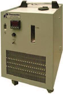
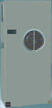
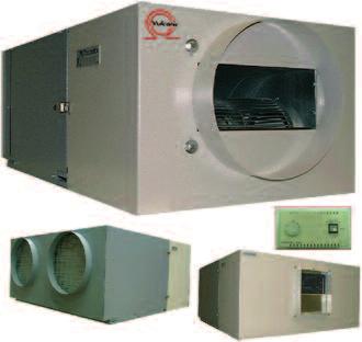
142 AIR CONDITIONING UNITS CHILLERS VULCAFROID DEHUMIDIFIERS EDENAIR 145

. - Ventilated hermetic compressor.")


 (V/ph/Hz) (mm) (mm) (mm) (kg) CAH 150 ME 80799-00 1460 230/1/50 400 600 400 49 CAH 150 TE 80745-00 1460 400/440/3/50/60 400 600 400 39 Front face Rear side")

.")
 (V/ph/Hz) (mm) (mm) (mm) (kg) 99002-16 1600* 230/1/50 395 400 780 65 99002-66 1600* 400/3/50 395 400 780 65 99002-25 2500* 230/1/50 395 400 780 65 99002-75 2500*")
143 AIR CONDITIONING UNITS AND LIQUID CHILLERS AIR-CONDITIONING UNITS FOR CABINETS Cooling power : from 360 to 2500 W (L35/L35 according to DIN 3168). To be fixed either on the front door or side panel or top panel of a cabinet. Factory pre-set to achieve an average cabinet temperature of 35 C max.. Front face Rear side + Customer s advantages - One single cut-out for cabinets from 850 to 2500 W. - Powerless condensation evaporating device. - Electronic control with alarms and safety values (high pressure, cabinet opened, cabinet temperature, fan and compressor s thermal breakers). - Ventilated hermetic compressor. - Standard spare parts for all models. Top mounted version Standard electronic controller AIR / WATER EXCHANGERS Cooling power : from 3900 to 6000 W (W10/L35 according to DIN 3168). To be fixed either on the front door or side panel of a cabinet. Factory pre-set to achieve an average cabinet temperature of 35 C max. Wall mounted air conditioners TYPE REF. Cooling power Voltage H L P Weight (W) (V/ph/Hz) (mm) (mm) (mm) (kg) CA 35 ME /1/ CA 85 ME /1/ CA 85 ME /1/ CA 120 ME /1/ CA 120 TE /440/3/50/ CA 170 ME /1/ CA 170 TE /440/3/50/ CA 210 ME /1/ CA 210 TE /440/3/50/ CA 250 TE /440/3/50/ Top mounted TYPE REF. Cooling power Voltage H L P Weight (W) (V/ph/Hz) (mm) (mm) (mm) (kg) CAH 150 ME /1/ CAH 150 TE /440/3/50/ Front face Rear side Cooling power at nominal water flow (W). RO400 RO600 Heat-transfer liquid 10 C 15 C 20 C 25 C 10 C 15 C 20 C 25 C temp. 430 l/h 690 l/h Cabinet 30 C temperature 35 C C TYPE REF. Voltage H L P Weight (V/ph/Hz) (mm) (mm) (mm) (kg) RO /1/50/ RO /1/50/ SELF-CONTAINED INDUSTRIAL CHILLERS VULCAFROID Chillers designed to cool down industrial process through a refrigerated water circulating in a closed loop (water with 5 % added glycol or ISO VG2 heat-transfer oil). Standard cooling power available from 1,6 to 30 kw. On request : other powers and medium temperatures. 146 Power Voltage H L P Weight (W) (V/ph/Hz) (mm) (mm) (mm) (kg) * 230/1/ * 400/3/ * 230/1/ * 400/3/ ** 230/1/ ** 400/3/ ** 400/3/ ** 400/3/ ** 400/3/ ** 400/3/ ** 400/3/ ** 400/3/ Power (W) ** for W10/L35 * for W20/L35 According to DIN 3168 / W10 = water temperature at 10 C / L35 = Air condensing temperature at 35 C

144 DEHUMIDIFIERS EDENAIR LIQUID CHILLER STL 200/250 These chillers are a self-contained cooling system for liquids, mobile and autonomus. Applications : Hot sources Pelletier Lasers Optical systems Features : Rubber feet. Handle for transport. Electronic PID controller. Adjustable high set point for safety temperature. Special and non corrosion treatment on heat exchanger. Internal liquid tank. Front mounted level control. Centrifugal pump with magnetic seal. Inlet and outlet for pipes Ø 8x10mm. Hermetic cooling compressor. Air condensing unit. Options : Flow switch 0,4 l/min or 1 l/min. Flow rate control with low flow safety contact. Water condenser. Electrical heating. Painted box with castors. Cooling power (W) Cooling power performance Temperature ( C) Pressure (bar) Water flow performance 0,5 0,4 0,3 0,2 0, Flow (litres/min) Characteristics TYPE STL 250 STL 200 Hermetic cooling compressor 1/6 CV W 1/5 CV W 1/6 HP W 1/5 HP W Cooling power (liquid 20 C Air 25 C) 180 W 230 W Air flow 120 m³/h ** 150 m³/h ** Supply voltage (50Hz) 230 V - 1ph 230 V - 1ph Current output 2A 2A Average power consumption ( 20 C - 80% HR) 160 W/h 180 W/h Refrigerant gas R134 a R134 a Water flow output (20 C - 0,25 bar) 6 l/min 6 l/min Reserve capacity 1,5 liters 1,5 liters Dimensions : P/L/H (mm) 370 x 290 x x 290 x 460 Weight 23 Kg 24 Kg Working capabilities 5 C up to 35 C - ambient 15 C up to 35 C DEHUMIDIFIER EDENAIR DP 1200, 3500, 5000 AND Applications : Warehouses Swimming pools Cellars Underground shelters Laboratories Drying processes : (buildings, wood, food and beverage, clothes ) Archives Green houses Gymnasium Covered stadium Features : Easily changeable air filter. Automatic defrosting. Two functions : ventilation only / ventilation and dehumidification. Adjustable controller from 0 up to 20 C, cut out the dehumidifier at low temperature. Cooper lined cold exchanger with protection against corrosion Options : Remote control with moisture controller. and 3 position cut out controller. Transformer incorporated (remote control 24 V). Electrical heating. Hot water heating exchanger. Temperature Characteristics Performance 40% 50% 60% 70% 80% 90% 40 C 30 C 20 C 10 C DP 1200 DP 3500 DP 5000 DP (values of DP x2) Condensed water Relative humidity Automatic defrosting Litres/day TYPE DP 1200 DP 3500 DP 5000 DP Hermetic cooling compressor 0,5 CV W 1,25 CV W 2 CV W 4 CV W 0,5 HP W 1,25 HP W 2 HP W 4 HP W Cooling power (liquid 20 C Air 25 C) 1400 W 3800 W 5250 W W Air flow 360 m³/h ** 900 m³/h ** 1500 m³/h ** 3000 m³/h ** Supply voltage (50Hz)* 230 V - 1ph 230 V - 1ph 230 V - 1ph 230 V - 1ph ou 400V - 3ph ou 400V - 3ph ou 400V - 3ph ou 400V - 3ph Electrical power consumption (20 C - 80% HR) 730 W 1500 W 2500 W 4200 W Power connexion : 3 x 1,5 2 3 x 2,5 2 3 x1,5 2 3 x1,5 2 or 4 x 1,5 2 or 4 x1,5 2 or 4 x1,5 2 Remote control 4 x x x x 1 2 Condensed water outlet (mm) Ø20 Ø20 Ø20 Ø20 Dimensions : P/L/H (mm) 630 x 425 x x 530 x x 610 x x 1120 x 572 Weight 40 Kg 85 Kg 110 Kg 210 Kg Volume treated 100 to 400m to 900m to 1750m to 3500m 3 * Others voltages and frequencies available for specific requirements ** Test bench CETIAT *** Value in DP 500 X2 147


145 DEHUMIDIFIERS EDENAIR DEHUMIDIFIERS EDENAIR VDM 750, 1200, 3500, 5000 AND C Performance Relative humidity 40% 50% 60% 70% 80% 90% Features : Casing adaptator for air duct connection. Designed in two parts for easy maintenance and handling during transport. Automatic defrosting allows temperature up to 0 C for VMD 750/1200 and 5 C for VMD 3500/5000 and Adjustable thermostat from -5 C up to 15 C in air inlet to switch off dehumidifier at low temperature. Cooper lined cold exchanger with protection against corrosion. Options : Remote controller with hygrostat and 3 positions switch : ventilation on, ventilation+ dehumidification and off. Internal transformer 24 V. Electrical heating with temperature controller. High pressure available reinforced at 10 mmce for VMD 750/1200 High pressure available reinforced at 20 mmce for VMD 3500/5000/ Hot water heat exchanger without controller. Water condenser. Applications : Warehouses Swimming pools Cellars Underground shelters Laboratories Drying processes : (buildings, wood, food and beverage, clothes ) Archives Green houses Gymnasium Covered stadium Temperature 30 C 20 C 10 C VMD 750 VMD 1200 VMD 3500 VMD 5000 VMD Automatic defrosting Condensed water Litres/day CHARACTERISTICS TYPE VDM 750 VDM 1200 VDM 3500 VDM 5000 VDM Hermetic cooling compressor 1,3 CV W 1,3 CV W 1,25 CV W 2 CV W 4 CV W Refrigerant gas R134 a R407 c R407 c R407 c R407c Cooling power (liquid 20 C Air 25 C) 870 W 1400 W 3800 W 5300 W W Air flow treated 300 m³/h 400 m³/h 900 m³/h 1500 m³/h 3000 m³/h Pressure available (CE) 5mm 5mm 10mm 10mm 10mm Air duct inlet outlet 250/ /250 Power supply (50Hz)* 230 V - 1ph 230 V - 1ph 230 V - 1ph 230 V - 1ph 230 V - 1ph or 400V - 3ph or 400V - 3ph or 400V - 3ph Electrical power consumption (20 C - 80% HR) 8/550 W 85/900 W 300/1500 W 450/2200 W 900/4200 W Water condensed outlet (mm) Ø16 Ø16 Ø20 Ø20 2 x Ø20 Dimensions : P/L/H (mm) 850 x 440 x x 440 x x 540 x x 630 x x 1300 x 575 Weight 34 Kg 41 Kg 90 Kg 120 Kg 200 Kg Heating power 1000 W 1000 W 2250 W 4500 W 9000 W Volume of the room to be treated 100 m to 400 m to 900 m to 1750 m to 3500 m 3 Temperature and humidity range 0 C to 37 C - 30% to 100% HR 5 C to 37 C - 30% to 100% HR Temperature DEHUMIDIFIERS EDENAIR T 750 AND Applications : Cellars Librairies Archives Photocopy centers Residences Restaurants Clothes dryers Boats Museums Green houses Performance 40% 50% 60% 70% 80% 90% 40 C 30 C 20 C 10 C T750 T Relative humidity Automatic defrosting Condensed water Litres/day Features : Options : Wheels. Pump for condensed water. Easy access Air filter - Efficiency 50%. Centrifugal fan for air duct network Hygrostat control - Accuracy +/- 7% 50 Pa (5 mm CE). Hot gas defrosting with automatic and thermostatic timer. Water exchanger. Level control contact safety. Electrical heater. High pressure contact safety. Hydraulic adapter for water connection on the customer network. May be built-in (on specific request). Cooper lined cold exchanger with protection against corrosion. * Others voltages and frequencies available for specific requirement ** Test bench CETIAT CHARACTERISTICS TYPE T 750 T1200 Hermetic cooling compressor 1/3 CV W 1/2 CV W 1/3 HP W 1/2 HP W Cooling power (liquid 20 C Air 25 C) 870 W 1400 W 2900 BTU 4750 BTU Air flow treated 300 m³/h ** 400 m³/h ** Power supply (50Hz) 230 V - 1ph 230 V - 1ph Electrical power consumption ( 20 C - 80% HR) 450 W 730 W Refrigerant gas R134 c R407 c Heating power 20 C - 80% HR 800 W 1200 W Tank for condensate 10 litre 20 litre Dimensions : P/L/H (mm) 420 x 410 x x 140 x 780 Weight 38 Kg 50 Kg
 Librairies Archives Photocopy centers Residences Restaurants Clothes dryers Features : Wheels. Easy access air filter - Efficiency 50%.")
. Water exchanger. Electrical heater. Water tank of 2 liters with automatic switch off.")
146 DEHUMIDIFIERS EDENAIR DEHUMIDIFIERS EDENAIR T 3500 AND 5000 Applications : Warehouses Swimming pools Cellars Tanks Underground shelters Silos Laboratories Drying proceses (wood, plaster, buildings, food and beverage) Librairies Archives Photocopy centers Residences Restaurants Clothes dryers Features : Wheels. Easy access air filter - Efficiency 50%. Hygrostat control - Accuracy +/- 7% Hot gas defrosting with automatic and thermostatic timer. Cooper lined cold exchanger with protection against corrosion. Options Pump for condensed water. Centrifugal fan for air duct network 50 Pa (5 mm CE). Water exchanger. Electrical heater. Water tank of 2 liters with automatic switch off. Temperature Performance 40% 50% 60% 70% 80% 90% 40 C 30 C 20 C 10 C T 3500 T 5000 Condensed water Relative humidity Automatic defrosting Litres/day 36 CHARACTERISTICS TYPE T 3500 T 5000 Hermetic cooling compressor 1,25 CV W 2 CV W 1,25 HP W 2 HP W Cooling power (liquid 20 C Air 25 C) 3800 W 5250 W BTU BTU Air flow treated 1000 m³/h ** 1500 m³/h ** Power supply (50Hz) 230 V - 1ph 230 V - 1ph 400 V - 3ph 400 V - 3ph Electrical power consumption ( 20 C - 80% HR) 1500 W 2200 W Refrigerant gas R407 c R407 c Heat output 20 C - 80%HR 2600 W 4000 W Water condensed outlet (mm) Ø16 Ø16 Dimensions : P/L/H (mm) 555 x 555 x x 655 x 1280 Weight 100 Kg 130 Kg Volume of the room to be treated 100 to 900 m to 1750 m 3 Temperature and humidity range 5 C to 35 C 30% to 100% H * Others voltages and frequencies available for specific requirements ** Test bench CETIAT DEHUMIDIFIERS EDENAIR T AND Applications : Warehouses Swimming pools Cellars Tanks Underground shelters Silos Laboratories Drying proceses (wood, plaster, buildings, food and beverage) Librairies Archives Photocopy centers Residences Restaurants Clothes dryers Small workshops Boats Museums Features : Wheels. Air filter easy access - Efficiency 50%. Hygrostat control - Accuracy +/- 7% Hot gas defrosting with automatic and thermostatic timer. Cooper lined cold exchanger with protection against corrosion. Options : Pump for condensed water. Centrifugal fan for air duct network 50 Pa (5 mm CE). Water exchanger. Electrical heater. Temperature 40 C 30 C 20 C 10 C T T Performance 40% 50% 60% 70% 80% 90% Relative humidity Automatic defrosting Condensed water Litres/day 480 CHARACTERISTICS TYPE T T Hermetic cooling compressor 1x4 CV - 4 kw 2x4 CV - 6 kw 2x4 HP - 2X3 kw Cooling power (liquid 20 C Air 25 C) 9500 W W BTU BTU Air flow treated 3000 m³/h ** 5300 m³/h ** Power supply (50Hz) 400 V - 3ph 400 V - 3ph Electrical power consumption (20 C - 80% HR) 4000 W 7500 W Refrigerant gas R407 c R407 c Heat output 20 C - 80%HR 7000 W W Water condensed outlet (mm) Ø20 Ø20 Dimensions : P/L/H (mm) 1110 x 660 x x 1350 x 1000 Weight 250 Kg 450 Kg Volume of the room to be treated 1500 to 3500 m to 8000 m 3 Temperature and humidity range 5 C to 35 C 30% to 100% H * Others voltages or frequency available on specific requirement ** Test bench CETIAT 149
Screw plug immersion heaters
 Screw plug HEATING GASES HEATING LIQUIDS MAINTAINING A CONTINUOUS TEMPERATURE The screw plug by CETAL are designed and manufactured as a standard range or according to customer specifications. Reliability
Flange immersion heaters
 Flange immersion heaters for ATEX/IECEx hazardous areas or in non-atex version HEATING GASES HEATING LIQUIDS MAINTAINING A CONTINUOUS TEMPERATURE CETAL flange immersion heaters are designed and manufactured
REGULATIONS EUROPEAN ATEX DIRECTIVE. INTERNATIONAL SCHEME: IECEx AREAS CLASSIFICATION DEFINED BY DIRECTIVE 1999/92/EC
 EUROPEAN ATEX DIRECTIVE > European Directive 2014/34/EU ATEX Directive 2014/34/EU is a "new approach" directive that applies to protective systems against explosions as well as all equipment used in or
Explosion-proof Immersion Heater Type D-8660
 Explosion-proof Immersion Heater Type D-8660 Sinus Jevi has developed explosionproof Ex de heating equipment, for hazardous area. The flame-proof (d) enclosures have been designed for non save areas to
Industrial Cast-in Circulation Heaters for ATEX/IECEx hazardous areas or in non-atex version
 heating for a better future Industrial Cast-in Circulation Heaters for ATEX/IECEx hazardous areas or in non-atex version HEATING GASES HEATING LIQUIDS The CETAL-developed Cast-In Circulation Heater Technology
Immersion heaters for ATEX/IECEx hazardous areas or in non-atex version
 for ATEX/IECEx hazardous areas or in non-atex version * Non contractual picture Warning It is imperative to read these instructions carefully before installing or maintaining the equipment. MI100EN 09/2017
IMMERSION HEATERS IMMERSION HEATERS FOR WATER 1½ BRASS NIPPLE, 3X400V: 2 BRASS NIPPLE, 3X400V:
 1½ or 2 RG IMMERSION HEATERS PAGE 1/5 Immersion heaters* are used to heat a variety of mediums, e.g. water, glycol, oil, and other liquids. It is important that the immersion heater is fitted to the side
Overview of Hazardous Locations as They Relate to Solenoid Valves
 Overview of Hazardous Locations as They Relate to Solenoid Valves Defined: Hazardous Location - "where fire or explosion hazards may exist due to flammable gases or vapors, flammable liquids, combustible
STRAIGHT & FORMED TUBULAR HEATERS
 STRAIGHT & FORMED TUBULAR HEATERS Applications: FORMING MACHINES HEATING MOLDS & PLATENS IMMERSION INTO LIQUIDS RADIANT & CONVECTION HEATING EMBEDDED OR CAST INTO METAL Tubular heaters are the main heating
Duct heaters for ATEX/IECEx hazardous areas or in non-atex version
 for ATEX/IECEx hazardous areas or in non-atex version * Non contractual picture Warning It is imperative to read these instructions carefully before installing or maintaining the equipment. MI200EN 09/2017
Hazardous Areas - EXPLOSIONPROOF SOLENOIDS
 Hazardous Areas - EXPLOSIONPROOF SOLENOIDS SOME HISTORY The classification of hazardous areas into zones established the level of protection required for electrical equipment installed in explosive gas
Beamex. Calibration White Paper. Calibration in hazardous areas
 Beamex Calibration White Paper info@beamex.com Calibration in hazardous areas This article discusses calibration in hazardous areas and what everyone needs to be aware of before entering into a hazardous
Tubular Industrial Process
 Application Tempco Over-the-Side Immersion Heaters are specifically designed for heating fluids in tanks. Depending on the tank shape, size, accessibility and working area inside the tank, choose a round
Guide for hazardous areas
 Guide for hazardous areas 1 Hazardous areas definitions 2 Gas and dust s 3 Temperature classifications 4 Common flammable gases, vapours and dust types 5 Protection concepts ATEX and IECEx 6 Protection
Weighing Solutions for Hazardous Areas FULL COMPLIANCE WITH ATEX DIRECTIVE
 Weighing Solutions for Hazardous Areas FULL COMPLIANCE WITH ATEX DIRECTIVE PUE HX5.EX explosion-proof hazardous area indicator ATEX APPROVAL PUE HX5.EX is a cutting-edge weighing indicator, designed to
Beamex Calibration White Paper. Calibration in hazardous areas
 Beamex Calibration White Paper info@beamex.com Calibration in hazardous areas This article discusses calibration in hazardous areas and what everyone needs to be aware of before entering into a hazardous
Circulation heaters for ATEX/IECEx hazardous areas or in non-atex version
 for ATEX/IECEx hazardous areas or in non-atex version * Non contractual picture Warning It is imperative to read these instructions carefully before installing or maintaining the equipment. MI500EN 09/2017
All in One Solutions
 VULCANIC The Vulcanic group has been designing and manufacturing electrical process heating and temperature control solutions since 1973. Employing 550 people across 8 manufacturing locations, Vulcanic
Tubular Heaters Series
 Tubular Heaters Series Immersion Heaters, Tubular Heaters, Ribbed Tubular Heaters Screw-in Immersion Heater Standard sizes for application in water Power (W) 2000 000 4500 6000 7500 Input Voltage (V) 20
Switches compliant with ATEX directive
 Switches compliant with ATEX directive General Catalogue - Technical concepts page Position switches FD / FL series page 9 / Category Zone EPL Approvals 2G Gb Mb II 2G Ex ia IIC T6 Gb I Ex ia I Mb Product
Dual certification! Air handling units for potentially explosive atmospheres
 Dual certification! Air handling units for potentially explosive atmospheres X-CUBE Ex A certified safety product The air handling unit with dual ATEX certification ATEX directive 2014/34/EU applies to
EJBX. Ex d. AISI 316L stainless steel. - Zone 1, 2, 21, 22 - Group IIB+H2 - Stainless steel junction boxes - Choice of 13 sizes - IP 66 / 67
 Ex d EJBX AISI 316L stainless steel - Zone 1, 2, 21, 22 - Group IIB+H2 - Stainless steel junction boxes - Choice of 13 sizes - IP 66 / 67 Quartz sand blasting Warning labels Mounting bracket Silicone gasket
UL HAZARDOUS LOCATIONS SERVICES
 UL HAZARDOUS LOCATIONS SERVICES The international preference in hazardous locations certification for over 100 years ul.com/hazloc Explosive Gas Atmospheres Class I Division S Includes flammable gases,
Tubular Industrial Process
 consist of tubular elements welded or brazed into a threaded screw plug which can then be inserted into a threaded opening in a tank wall or through a mating full or half coupling. Standard Screw Plug
PYROS. Código: FT-PY01-I Revisión: TECHNICAL DATA. Polycarbonate tube of 4 mm. thickness LIGHT FITTING. Laquered steel painted white
 . TECHNICAL DATA LIGHT FITTING REFLECTOR Polycarbonate tube of 4 mm. thickness Laquered steel painted white END CAPS Aluminium 2030 (polyester paint RAL 7047) POWER SOURCE LAMP TYPE 220-240V, 50/60Hz T8
Hazardous area descriptions
 Hazardous area descriptions National Electrical Code (NEC) 500 Traditional standards used in North America. Example: Class I, Div 1, Group B, C, D, T4 Permitted Class Permitted Division Permitted Group
Immersion Heaters. Screw Plug Immersion Heater
 Screw plug immersion heaters are ideal for direct immersion heating of liquids, including all types of oils and heat transfer solutions. Available in a variety of sizes, screw plug immersion heaters feature
SCREW PLUG IMMERSION HEATERS
 SCREW PLUG IMMERSION HEATERS ELECTRIC PROCESS HEATER SOLUTIONS BEGIN HERE... Electric heaters are our only business. We are specialists in designing, engineering, and manufacturing both standard and custom
BRINGING WARMTH TO YOUR WORLD
 BRINGING WARMTH TO YOUR WORLD In our Elements brochure you will find reference to many of the different types of electric heating elements we produce both in our Manchester factory and in our group companies
OWNER S MANUAL LOW-POWER SCREW-IN AND FLANGE-MOUNTED IMMERSION HEATERS (MAXIMUM 3 PINS)
") 1/5 VULCANIC S.A. - 48, rue Louis Ampère Zone Industrielle des Chanoux - F 93330 NEUILLY / MARNE (France) Tél. (33) 01.49.44.49.20 - Fax (33) 01.49.44.49.41 OWNER S MANUAL LOW-POWER SCREW-IN AND FLANGE-MOUNTED
1/5 VULCANIC S.A. - 48, rue Louis Ampère Zone Industrielle des Chanoux - F 93330 NEUILLY / MARNE (France) Tél. (33) 01.49.44.49.20 - Fax (33) 01.49.44.49.41 OWNER S MANUAL LOW-POWER SCREW-IN AND FLANGE-MOUNTED
Heated tools. Semiconductor equipment
 Heated tools Semiconductor equipment Ceramic heating elements made of silicon nitride and aluminum nitride can be manufactured as tools in various shapes. The heating function can be integrated in complex
HEATING ELEMENTS FOR WATER HEATING output 500W W water and similar liquid heating
 HEATING EEMENTS FOR WATER HEATING output 0W 33.000 W water and similar liquid heating Specification: Heating elements for water and similar liquid heating with no danger of medium carbonization on the
INSTRUCTION MANUAL (ATEX / IECEx)
") INSTRUCTION MANUAL (ATEX / IECEx) BExS110D and BExS110D-R Sounder For use in Flammable Gas and Dust Atmospheres BExS110D BExS110D-R 1) Warnings DO NOT OPEN WHEN AN EXPLOSIVE ATMOSPHERE IS PRESENT DO NOT
INSTRUCTION MANUAL (ATEX / IECEx) BExS110D and BExS110D-R Sounder For use in Flammable Gas and Dust Atmospheres BExS110D BExS110D-R 1) Warnings DO NOT OPEN WHEN AN EXPLOSIVE ATMOSPHERE IS PRESENT DO NOT
Circulation Heaters Selection Guidelines
 Selection Guidelines Selecting a Circulation Heater Application Factors Corrosion Policy Selecting the proper circulation heater component requires critical engineering judgement and careful evaluation
Flow switch. Operating Manual. English manual page Page 1 of 15 Fax:
 Operating Manual www.jlso-tec-trade.de Flow switch English manual page 1-15 Page 1 of 15 Flow switch Table of Contents Page 1 Device Description and Intended Use... 19 1.1 Flow switch version VH...X...
1. GENERAL TECHNICAL INFORMATION
 1. GENERAL TECHNICAL INFORMATION 1.1 EXPLOSIVE ATMOSPHERES: Every time that dangerous quantities and concentration of flammable gas, vapors mixture or dust clouds exists, risk of explosions may arise.
Explosion-protected actuator Page 259 of 292
 Explosion-protected actuator Page 259 of 292 9.5 Explosion-protected actuator 9.5.1. What is an explosion? A flammable substance and oxygen, in a certain mixture, must be available to set off an explosion.
Technical Information
 Watt Density & Heater Selection - Guidelines Understanding Watt Density Watt density (W/in ) is the heat flux emanating from each square inch of the effective heating area (heated surface) of the element.
Officine Meccaniche M.A.M. series for command, control, signaling and/or automation. DOCUMENT IS-EJB-A-14 rev. 0
 Officine Meccaniche M.A.M. Apparecchiature Antideflagranti DOCUMENT IS-EJB-A-14 rev. 0 Instructions Flameproof enclosures EJB../W series for command, control, signaling and/or automation Emission date:
Electric Air Heating Standard product ranges
 heating for a better future Electric Air Heating Standard product ranges For all your standard air heating applications Fin heaters page 2-5 Industrial convectors page 6-9 Duct heaters page 10-14 www.cetal.com
Sinus Jevi (Explosion-Proof) Condens Heaters
 Condens Heaters") Sinus Jevi (Explosion-Proof) Condens Heaters Heating elements for dehumidification of sealed switchboards and control cabinets. Due to temperature limitations on e.g. print and plastic cabinets it is important
Sinus Jevi (Explosion-Proof) Condens Heaters Heating elements for dehumidification of sealed switchboards and control cabinets. Due to temperature limitations on e.g. print and plastic cabinets it is important
HEATERS MOUNTED ON THREADED PLUG
 Figure 1: Typical sketch of an electric heater mounted on a threaded plug GENERAL CHARACTERISTICS The electric heaters mounted on a threaded plug have been conceived to satisfy the most different needs
Selection of Explosion Protected Equipment for Hazardous Locations. Compiled by: Pieter Coetzee ZONE 2 ZONE 1 ZONE 0.
 Selection of Explosion Protected Equipment for Hazardous Locations Compiled by: Pieter Coetzee ZONE 2 ZONE 0 ZONE 1 Be safe be Ex Contents Introduction Occupational Health and Safety Act. (Act 85 of 1993)
C D E F. Tubular Industrial Process Circulation Heaters. Circulation Heaters. View Product
 Self-contained heating units designed for optimum operating efficiency and performance Providing trouble-free service and application flexibility! All of the heat generated by the elements is immediately
The R. STAHL Technology Group Worldwide Success with Competence and Customer Support
 The R. STAHL Technology Group Worldwide Success with Competence and Customer Support The entrepreneurial basis of the R. STAHL Technology Group follows a long tradition. The product range is aimed at specialised
Drive Technology \ Drive Automation \ System Integration \ Services * _0817* Inquiry Forms for Explosion-Proof Gearmotors
 Drive Technology \ Drive Automation \ System Integration \ Services *23511257_0817* Inquiry Forms for Explosion-Proof Gearmotors Edition 08/2017 23511257/EN SEW-EURODRIVE Driving the world Inquiry forms
Screw Plug Immersion Heaters
 Overview consist of hairpin bent tubular elements brazed or welded into a screw plug and provided with terminal enclosures for electrical connections. are screwed directly through a threaded opening in
Defrosting. Flexible Heating Elements. DEFA, DEFB, DEFC range. Straight annealed elements adaptable for evaporators or tray defrosting, DEFA range
 Flexible Heating Elements DEFA, DEFB, DEFC range Straight annealed elements adaptable for evaporators or tray defrosting, DEFA range page 2 Straight annealed elements for evaporators or tray defrosting,
MICROpeL 75 Combustible Gas Sensor Part Number: PM
 MICROpeL 75 Combustible Gas Sensor Part Number: PM759-000 Key Features & Benefits: ATEX, UL and CSA Approvals Withstands EN/IEC 60079-0 impact test Enhanced H 2 S and silicone poison resistance Reduced
ATM Lighting sp. z o.o
 INSTALLATION AND MAINTENANCE MANUAL FOR EXPLOSIONPROOF LIGHT FITTING EXL210LED Carefully read the instructions before mounting the light fitting. ATM Lighting sp. z o.o., ul. Budowlanych 31, 80-298 Gdańsk,
STAINLESS STEEL FLAMMABLE GAS DETECTOR DAX 3F-I INSTALLATION, OPERATING AND MAINTENANCE INSTRUCTIONS. DAX3FI_MAN01_EN Ver. V1R2
 STAINLESS STEEL FLAMMABLE GAS DETECTOR INSTALLATION, OPERATING AND MAINTENANCE INSTRUCTIONS DAX3FI_MAN01_EN Ver. V1R2 1 Introduction These instructions must be read carefully by any person who has or will
Circulation Heaters. To order, call or shop online at omega.com SM. CHF Series
 CHF Series Self-contained heating units designed for optimum operating efficiency and performance Providing trouble-free service and application flexibility! All of the heat generated by the elements is
A GUIDE TO EUROPEAN (EEC) CERTIFICATION FOR ELECTRICAL EQUIPMENT IN HAZARDOUS AREAS
 CERTIFICATION FOR ELECTRICAL EQUIPMENT IN HAZARDOUS AREAS") A GUIDE TO EUROPEAN (EEC) CERTIFICATION FOR ELECTRICAL EQUIPMENT IN HAZARDOUS AREAS For a print friendly page click here INTRODUCTION Hazardous areas are those in which there exists a risk of explosion
A GUIDE TO EUROPEAN (EEC) CERTIFICATION FOR ELECTRICAL EQUIPMENT IN HAZARDOUS AREAS For a print friendly page click here INTRODUCTION Hazardous areas are those in which there exists a risk of explosion
Circulation Heaters. To order, call or shop online at omega.com SM. CHF Series
 CHF Series Self-contained heating units designed for optimum operating efficiency and performance Providing trouble-free service and application flexibility! All of the heat generated by the elements is
Additional Operating Instructions SITRANS F. Vortex flowmeters. SITRANS FX330 Ex-d.
 Additional Operating Instructions SITRANS F Vortex flowmeters Ex-d Edition 09/208 CONTENTS Safety instructions 3. General notes... 3.2 EU conformity... 3.3 Approval according to the IECEx scheme... 3.4
Circulation Heaters. To order, call or shop online at omega.com SM. CHF Series
 CHF Series Self-contained heating units designed for optimum operating efficiency and performance Providing trouble-free service and application flexibility! All of the heat generated by the elements is
The Safest Connections...
 The Fluid Manager The Safest Connections... The Lutz Accessory Range for Electrical & Pneumatic Drum, Tote and Container Pumps A c c e s s o r y R a n g e Accessory Range Safety is our Concern At a glance
Flanged Immersion Heaters
 Flanged Immersion Heaters Are designed for use in tanks and pressurized vessels to heat both liquids and gases. They mate to a companion flange that is either welded to a tank wall or, for circulating
Circulation Heaters. To order, call or shop online at omega.com SM. CHF Series
 CHF Series Self-contained heating units designed for optimum operating efficiency and performance Providing trouble-free service and application flexibility! All of the heat generated by the elements is
Hazardous Area Portable Fan Heater The Bulldog
 Hazardous Area Portable Fan Heater The Bulldog www.exheat-industrial.com MFH The Bulldog Portable Fan Heater EXHEAT Industrial s MFH The Bulldog Portable Fan Heater is the world s first truly portable
Airo Wireless Intrinsically Safe White Paper. Written By: David Schmitt
 Airo Wireless Intrinsically Safe White Paper Written By: David Schmitt Intrinsically Safe Cell Phone/Smartphone/PDA Intrinsically Safe (IS) is a protection certification for safe operation with electronic
Intrinsically Safe Pressure Transmitters for installation in hazardous locations Models IS-20-S, IS-21-S, IS-20-F, IS-21-F WIKA Datasheet IS-20
 Electronic Pressure Measurement Intrinsically Safe Pressure Transmitters for installation in hazardous locations Models IS-20-S, IS-21-S, IS-20-F, IS-21-F WIKA Datasheet IS-20 Applications Chemical, Petrochemical
HEATERS & SENSORS INC. - CATALOG
 HEATERS & SENSORS INC. - CATALOG Mica Band Heaters Efficient, Reliable and Economical Solution Maximum 900 ⁰F Operating Temperatures Build according to custom specifications Holes and cut-outs are available
CYLINDER PLASTICS CERAMIC BAND HEATERS. Main technical characteristics: Mechanics. Electrics
 CERAMIC BAND HEATERS These heaters are made up of a spiral in NiCr 80/20 or FeCrAl alloy inserted in steatite modular elements, while the outer casing is made of sheet Alusi or, upon request, stainless
INSTRUCTION & SERVICE MANUAL
 INSTRUCTION & SERVICE MANUAL D2xC1 ALARM HORN AND STROBE For Use In Hazardous Locations 3) Ratings and Markings 3.1 ATEX / IECEx certification The D2xC1 Alarm Horn and Strobe complies with the following
Circulation Heaters. To order, call or shop online at omega.com SM. CHF Series
 CHF Series Self-contained heating units designed for optimum operating efficiency and performance Providing trouble-free service and application flexibility! All of the heat generated by the elements is
CHGV AIR COOLED WATER CHILLER WITH HYDRAULIC EQUIPMENT AIR / WATER 47 to 78 kw
 TECHNICAL INSTRUCTIONS CHGV AIR COOLED WATER CHILLER WITH HYDRAULIC EQUIPMENT AIR / WATER 47 to 78 kw CHGV CHGV 64 CHGV 72 CHGV 80 PHRV heat pump model also available May 2006 10 12 167 - GB - 00 MARKING
INSTRUCTION MANUAL (ATEX/IECEx/SIL2) BExBG05D-SIL Flameproof Xenon SIL 2 Beacons For use in Flammable Gas and Dust Atmospheres
 BExBG05D-SIL Flameproof Xenon SIL 2 Beacons For use in Flammable Gas and Dust Atmospheres") INSTRUCTION MANUAL (ATEX/IECEx/SIL2) BExBG05D-SIL Flameproof Xenon SIL 2 Beacons For use in Flammable Gas and Dust Atmospheres 1) Introduction The BExBG05D-SIL is a flameproof beacon which is certified
INSTRUCTION MANUAL (ATEX/IECEx/SIL2) BExBG05D-SIL Flameproof Xenon SIL 2 Beacons For use in Flammable Gas and Dust Atmospheres 1) Introduction The BExBG05D-SIL is a flameproof beacon which is certified
MEGAWAT * HIGH DENSITY CARTRIDGE HEATERS
 MEGAWAT * HIGH DENSITY CARTRIDGE HEATERS MEGAWAT high-density cartridges are round tubular heaters with electrical terminations on one side. These dependable heaters are made to withstand tough industrial
ATEX - GUIDE. A short introduction to ATEX Terminology. Equipment for use in flammable atmospheres C E R T I F I E D DANISH TECHNOLOGICAL INSTITUTE
 DANISH TECHNOLOGICAL INSTITUTE The Danish Technological Institute is a self-owned and not-f-profit institution. We develop, apply and disseminate research- and technologically-based knowledge f the Danish
LTFX Electric Tank Immersion Heaters Installation Instructions
 LTFX Electric Tank Immersion Heaters Installation Instructions 1 PN403-5 161-049178-101 March 2017 LTFX Electric Tank Immersion Heater Installation Instructions General The Chromalox Electric Tank Immersion
GTF 103-Ex. GREISINGER electronic GmbH D Regenstauf, Hans-Sachs-Straße 26. Temperature Probe for potentially explosive atmospheres
 Z31.0.XX.6C-11 Temperature Probe for potentially explosive atmospheres (Measuring ranges from -200 to +900 C) Operating Manual GTF 103-Ex 0081 GREISINGER electronic GmbH D - 93128 Regenstauf, Hans-Sachs-Straße
Flanged Immersion Heaters
 Flanged Immersion Heaters Are designed for use in tanks and pressurized vessels to heat both liquids and gases. They mate to a companion flange that is either welded to a tank wall or, for circulating
EXHEAT Industrial Standard Products
 Standard Products EXHEAT Industrial Standard Products EXHEAT Industrial offers fast track solutions to the industry s wide and varied requirements for electrical heating systems. All our heaters are manufactured
Circulation Heaters Selection Guidelines
 Selection Guidelines Selecting a Circulation Heater Application Factors Corrosion Policy Selecting the proper circulation heater component requires critical engineering judgement and careful evaluation
Flammable gases Detectors. Model DAX 03F DAX 03F- C DAX 03F- H. Note for installation, use and maintenance. Version 1.2
 Flammable gases Detectors Model DAX 03F DAX 03F- C DAX 03F- H Note for installation, use and maintenance Version 1.2 Introduction This handbook must be read carefully by any person who has or will have
THE BELGIAN PIONEER IN GAS DETECTION
 DAT 420 Gas or oxygen detector INSTRUCTION MANUAL THE BELGIAN PIONEER IN GAS DETECTION Copyright 2016 by DALEMANS s.a. Revision V1R7 07/2016 Any reproduction, whether partial or entire, made of this document,
Hand pump JP-02. Hand pump JP-02 for acids, alkalies and water-based chemicals. depending on lever position. The telescopic suction tube is adjustable
 Hand pump JP-02 Hand pump JP-02 for acids, alkalies and water-based chemicals Shaft: Stainless steel 316 Ti Seals: Viton Flow rate: 0,3, 0,37 or 0,45 l/stroke* depending on lever position from 340 to 900
Fan Heaters Type VLEx
 Fan Heaters Type VLEx Fan Heater type VLEx has been designed for Explosion Proof industrial applications. Our Fan Heaters are characterized mainly by their quality, both in used materials and design. Liquids
INSTALLATION, OPERATING & MAINTENANCE INSTRUCTIONS FOR 350 SERIES CIRCULATION HEATERS
 INDEECO Circulation Heaters are designed to provide years of trouble free operation if properly installed and maintained. Please read and follow these instructions for installing and maintaining the heater.
Gasketed and brazed plate heat exchangers
 Gasketed and brazed plate heat exchangers Contents Gasketed plate heat exchangers Options Brazed plate heat exchangers Options 14 22 30 32 www.fiorinigroup.it 11 Gasketed and brazed plate heat exchangers
Circulation Heaters. To order, call or shop online at omega.com SM. CHF Series
 CHF Series Self-contained heating units designed for optimum operating efficiency and performance Providing trouble-free service and application flexibility! All of the heat generated by the is immediately
ELECTRICAL HEAT EXCHANGER FOR PROCESS INDUSTRY
 ELECTRICAL HEAT EXCHANGER FOR PROCESS INDUSTRY ELECTRICAL HEAT EXCHANGER FOR PROCESS INDUSTRY Gas/Oil/Water Separation Hazardous area Immersion Crude oil Air treatment Steam generators Comfort Storage
Flanged Immersion Heaters
 Flanged Immersion Heaters Are designed for use in tanks and pressurized vessels to heat both liquids and gases. They mate to a companion flange that is either welded to a tank wall or, for circulating
1592P01. for liquids in piping DN max. DC 48 V, 1 A, 20 W
 594 59P0 Flow switch for liquids in piping DN 0 00. QE90 Contact load / switching capacity: Nominal pressure PN5 Manual setting of contact type (NO / NC) Housing IP 65 / safety class II Maintenance free
OPTIWAVE X500 Supplementary Instructions
 OPTIWAVE X500 Supplementary Instructions OPTIWAVE 3500 C OPTIWAVE 6500 C OPTIWAVE 7500 C Supplementary Instructions for ATEX applications KROHNE CONTENTS OPTIWAVE X500 1 General safety information 4 1.1
W A T L O W. Straight Resistance Wire. Welded End Cap
 W A T L O W The versatile Watlow cable heater can be formed to a variety of shapes as dictated by its many applications. Cable heaters are small diameter, high performance units, fully annealed and readily
ELECTRICAL HEAT EXCHANGER FOR PROCESS INDUSTRY
 ELECTRICAL HEAT EXCHANGER FOR PROCESS INDUSTRY ELECTRICAL HEAT EXCHANGER FOR PROCESS INDUSTRY Gas/Oil/Water Separation Hazardous area Immersion Crude oil Air treatment Steam generators Comfort Storage
Connect - Contact - Control. Air and water heaters for rail vehicles Ø22. F 195.en
 Connect - Contact - Control Air and water heaters for rail vehicles 21 0 60 60 0 0 R 90 F 19.en 2 Heaters for rail vehicles Development and manufacture of heaters for rail vehicles has a tradition for
EN54-5, ATEX and IECEx approved Highly durable Automatic reset after cooling Range of alarm temperatures
 EN54-5, ATEX and IECEx approved Highly durable Automatic reset after cooling Range of alarm temperatures HDL-3-EX* Complete and ready to install Heat Detector with Ex-certified Box, Cable gland and wiring
IMMERSION HEATERS GAS AND BSP
 IMMERSION HETERS GS ND SP INDEX Screw plug tubular heaters M77x200 with thermowell pag. 04 Screw plug tubular heaters 1 1/2 pag. 05-08 Screw plug tubular heaters 1 1/4 pag. 09-10 Screw plug tubular heaters
INSTRUCTION MANUAL (ATEX / IECEx)
") INSTRUCTION MANUAL (ATEX / IECEx) BExBG15E and BExBG10E Flameproof / Increased Safety Xenon Beacons For use in Flammable Gas and Dust Atmospheres 1) Introduction The BExBG15E and BExBG10E beacons are flameproof
INSTRUCTION MANUAL (ATEX / IECEx) BExBG15E and BExBG10E Flameproof / Increased Safety Xenon Beacons For use in Flammable Gas and Dust Atmospheres 1) Introduction The BExBG15E and BExBG10E beacons are flameproof
Hazardous Area Portable Fan Heater The Bulldog
 Hazardous Area Portable Fan Heater The Bulldog www.exheat-industrial.com MFH The Bulldog Portable Fan Heater EXHEAT Industrial s MFH The Bulldog Portable Fan Heater is the world s first truly portable
ATM Lighting sp. z o.o
 INSTALLATION AND MAINTENANCE MANUAL FOR EXPLOSIONPROOF LIGHT FITTING EXL390LED Carefully read the instructions before mounting the light fitting. ATM Lighting sp. z o.o., ul. Budowlanych 31, 80-298 Gdańsk,
Unheated straight section Fast response time Choice of lead protection Longer heater life Higher watt densities Made to customer specifications
 Temperatures up to 800 F (982 C) Precise temperature control Choice of lead orientation Built-in type J or K Thermocouple Round, square and rectangular cable Rugged, durable construction MIGHTYBAND The
CHGV AIR COOLED WATER CHILLER WITH HYDRAULIC EQUIPMENT AIR / WATER 47 to 78 kw
 TECHNICAL INSTRUCTIONS CHGV AIR COOLED WATER CHILLER WITH HYDRAULIC EQUIPMENT AIR / WATER 47 to 78 kw CHGV 50 CHGV 64 CHGV 72 CHGV 80 PHRV heat pump model also available November 2007 10 12 167 - GB -
CHGV AIR COOLED WATER CHILLER WITH HYDRAULIC EQUIPMENT AIR / WATER 21 to 39 kw
 TECHNICAL INSTRUCTIONS CHGV AIR COOLED WATER CHILLER WITH HYDRAULIC EQUIPMENT AIR / WATER 21 to 39 kw CHGV 22 CHGV 2 CHGV 32 CHGV 40 PHRV heat pump model also available September 2007 10 12 11 - GB - 02
Explosion protection Marijan Gorše, dipl. ing.
 Explosion protection Marijan Gorše, dipl. ing. 1/18 Flammable Gas Atmosphere We Can Control Them Explosion hazards mostly arise from flammable gases and vapours. Instead of avoiding their ignition by explosion
Checklist Selecting the Proper Flanged Heater
 are designed for use in tanks and pressurized vessels to heat both liquids and gases. They mate to a companion flange that is either welded to a tank wall or, for circulating type heaters, to a pipe. See
ATEX, NOMENCLATURE AND CODING
 Technical Notes ATEX, NOMENCLATURE AND CODING The intent of this technical note is approach to the user to the ATEX normative. For this we will begin defining, what is an explosive atmosphere, what are