DEPARTMENT OF THE ARMY TECHNICAL MANUAL
|
|
|
- Ellen Williams
- 5 years ago
- Views:
Transcription
1 This copy is a reprint which includes current pages from Changes 1 through 10. TM DEPARTMENT OF THE ARMY TECHNICAL MANUAL TECHNICAL MANUAL OPERATOR, ORGANIZATIONAL, DIRECT SUPPORT AND GENERAL SUPPORT MAINTENANCE MANUAL AIR CONDITIONER, HORIZONTAL COMPACT 18,000 BTU TRANE MODELS 208V, 3 PHASE, 50/60 HERTZ, MODEL MAC6H (FSN ) 208V, 3 PHASE, 400 HERTZ, MODEL MAC4H (FSN ) 230V, 1 PHASE, 50/60 HERTZ, MODEL MAC6H (FSN ) HEADQUARTERS, DEPARTMENT OF THE ARMY 28 OCTOBER 1971
2 WARNING HIGH VOLTAGE is used in the operation of this equipment, DEATH ON CONTACT or severe injury may result if personnel fail to observe safety precautions. Always disconnect the air conditioner from power source before performing maintenance on this equipment. Do not operate the air conditioner without louvers, top covers, and guards in place and tightly secured. WARNING REFRIGERANT UNDER PRESSURE is used in the operation of this equipment, DEATH or severe injury may result if personnel fail to observe safety precautions. Never use a heating torch on any part that contains refrigerant-22. Avoid bodily contact with liquid refrigerant and avoid inhaling refrigerant gas.
3 Changes in force C1 thru C11 TM C11 CHANGE No. 11 HEADQUARTERS DEPARTMENT OF THE ARMY WASHINGTON, D.C., 21 NOVEMBER 1995 Operator s, Organizational, Direct Support, and General Support Maintenance Manual AIR CONDITIONER, HORIZONTAL, COMPACT, 18,000 BTU, 208 V, 3 PHASE, HERTZ HARVEY W. HOTTEL MODEL CH NSN AMERICAN AIR FILTER MODEL AACH NSN V, 3 PHASE, 400 HERTZ TRANE MODEL MAC4H NSN HARVEY W. HOTTEL MODEL CH , NSN KECO MODEL KIF-18H-4 NSN DISTRIBUTION STATEMENT A: Approved for public release; distribution is unlimited. TM , 28 October 1971, is changed as follows: Title is changed to read as shown above. Page 1-1, paragraph 1-3 is superseded as follows: REPORTING ERRORS AND RECOMMENDING IMPROVEMENTS You can help improve this manual. If you find any mistakes or if you know of a way to improve these procedures, please let us know. Mail your letter or DA Form 2028 (Recommended Changes to Publications and Blank Forms), or DA Form located in the back of this manual directly to: Commander, US Army Aviation and Troop Command, ATTN: AMSAT-I-MP, 4300 Goodfellow Blvd., St. Louis, MO You may also submit your recommended changes by directly to <daf2028@st-louis-emh7.army.mil>. A reply will be furnished directly to you. Correct mailing address for Equipment Improvement Recommendation (EIR) is: Commander U.S. Army Aviation and Troop Command ATTN: AMSAT-I-MDO 4300 Goodfellow Blvd. St. Louis, MO

4 TM C 11 Page 2-1, paragraph 2-4. Add the following CAUTION: CAUTION Prior to connecting and disconnecting power cable, ensure ON/OFF circuit breaker is in the off position Page 4-6, Prior to Paragraph SERVICING RETURN AIR FILTER, Add the following personnel WARNING: Gloves should be worn when servicing or replacing the return air filter due to sharp edges. All sharp edges should be filed down to prevent future potential injuries. By Order of the Secretary of the Army: Official: DISTRIBUTION: To be distributed in accordance with DA Form E, block no. 0070, requirements for TM PIN:
5 Changes in force: C1 thru C10 TM C 10 CHANGE NO. 10 HEADQUARTERS DEPARTMENT OF THE ARMY WASHINGTON, D.C., 1 JULY 1992 Operator s, Organizational, Direct Support, and General Support and Depot Maintenance Manual AIR CONDITIONER, HORIZONTAL, COMPACT, 18,000 BTU, 208 V, 3 PHASE, HERTZ HARVEY W. HOTTEL MODEL CH NSN AMERICAN AIR FILTER MODEL AACH NSN V, 3 PHASE, 400 HERTZ TRANE MODEL MAC4H , NSN HARVEY W. HOTTEL MODEL CH , NSN KECO MODEL KIF 18H-4 NSN Approved for public release; distribution is unlimited TM , 28 October 1971, is changed as follows: Page 1-1, paragraph 1-3 is superseded as follows: You can help improve this manual. If you find any mistake or if you know of a way to improve the procedure, please let us know. Mail your letter or DA Form 2028 (Recommended Changes to Publications and Blank Forms) directly to: Commander, U.S. Army Troop Support Command, ATTN: AMSTR-MMTS, 4300 Goodfellow Blvd., St. Louis, MO A reply will be furnished to you. Page 6-2 is changed as follows: Paragraph 6-3b, Discharging and Purging System, add the following note: NOTE In accordance with Environmental Protection Agency regulations, refrigerants cannot be discharged into the atmosphere. A recovery/recycling unit must be used whenever discharging the unit. Operation of the recovery/recycling unit must be by AUTHORIZED PER- SONNEL ONLY. Page 6-3 is changed as follows: Figure 6-1, Discharging and evacuating refrigerant system, the discharging portion of this illustration is superseded as follows: TO DISCHARGE SYSTEM: CONNECT AND OPERATE RECOVERY/RECYCLE UNIT IN ACCORDANCE WITH THE MANUFACTURER S INSTRUCTIONS. 1

6 TM C10 Page 6-4 is changed as follows: Figure 6-2, Charging refrigerant system, (sheet 1 of 2), add following note: NOTE Whenever available, use recycled refrigerant for charging the refrigeration system. Page B-4 is changed as follows: SECTION III. TOOLS AND TEST EQUIPMENT REQUIREMENTS is superseded as shown: TOOL OR TEST MAINTENANCE NOMENCLATURE NATIONAL/NATO STOCK TOOL EQUIPMENT CATEGORY NUMBER NUMBER REF CODE F-H Recovery and Recycling Unit, Refrigerant B (07295) By Order of the Secretary of the Army: Official: GORDON R. SULLIVAN General, United States Army Chief of Staff MILTON H. HAMILTON Administrative Assistant to the Secretary of the Army DISTRIBUTION: To be distributed in accordance with DA Form 12-25E, qty rqr block no
7 Changes in force: C1, C2, C3, C4, C5, C6, C7, C8, and C9 TM C9 CHANGE HEADQUARTERS DEPARTMENT OF THE ARMY NO. 9 WASHINGTON, D. C., 20 November 1990 Operator s, Organizational, Direct Support, General Support and Depot Maintenance Manual AIR CONDITIONER, HORIZONTAL, COMPACT, 18,000 BTU, 208 V, 3 PHASE, HERTZ HARVEY W. HOTTEL MODEL CH NSN AMERICAN AIR FILTER MODEL AACH-618-2NSN V, 3 PHASE 400 HERTZ TRANE MODEL MAC4H NSN HARVEY W. HOTTEL MODEL CH NSN KECO MODEL KIF-18H-4 NSN Approved for public release; distribution is unlimited TM , 28 October 1971 is changed as follows: Page 2 12, paragraph 2 13 is superseded as follows: Operation in Extreme Heat. NOTE Unit Preventive Maintenance Checks and Services (PMCS) should be performed at daily intervals. a. General. The air conditioner is designed to operate in temperatures up to 120 F (49 C). Extra care should be taken to minimize the cooling load when operating in extreme high temperatures. b. Protection. (1) Check all openings in the enclosure, especially doors and windows, to be sure they are tightly closed. Limit in and out traffic if possible. (2) When appropriate, use shades or awnings to shut out direct rays of the sun. ventilation. (3) (4) When possible, limit the use of electric lights and other heat producing equipment. Limit the amount of hot, outside air introduced through the fresh air damper to that essential for NOTE Weatherstripping, the installation of storm doors, and windows, if appropriate, and insulation of surfaces exposed to the outside is recommended when operating in extremely high temperatures for extended periods. c. Cleaning. (1) Clean outside grilles, coils, filters, and mist eliminator more frequently. 1
8 TM Page 2 12, paragraph 2 14 is superseded as follows: Operation in Dusty or Sandy Conditions. NOTE Unit Preventive Maintenance Checks and Services (PMCS) should be performed at daily intervals. a. General. Dusty and sandy conditions can seriously reduce the efficiency of the air conditioner by clogging the air filter, mist eliminator, and coils. This will cause a restriction in the volume of airflow. Accumulation of dust or sand in the condenser coil and/or in the compressor compartment may cause overheating of the refrigeration system. Dust or sand may also clog the condensate trap and water drain lines. b. Protection. CAUTION Never operate the air conditioner without having the air filters in place. (1) Shield the air conditioner from dust as much as possible. (2) Take advantage of any natural barriers which offer protection. (3) Limit the amount of dusty or sandy outside air introduced through the fresh air damper. (4) Roll down and secure the fabric cover on the back of the cabinet during periods of shutdown. c. Cleaning. (1) Keep the air conditioner as clean as possible. (2) Pay particular attention to the outside grilles, condenser, filters, mist eliminator, louvers, and electrical components. (3) In extreme conditions, daily cleaning of condenser, filters, and outside grilles may be necessary. By Order of the Secretary of the Army: Official: THOMAS F. SIKORA Brigadier General, United States Army The Adjutant General CARL E. VUONO General, United States Army Chief of Staff DISTRIBUTION: To be distributed in accordance with DA Form 12-25E, (qty rqr block no. 0070) 2
9 Changes in force: C1, C2, C3, C4, C5, C6, C7 and C8 TM C8 CHANGE HEADQUARTERS DEPARTMENT OF THE ARMY No. 8 WASHINGTON, D.C., 21 March 1988 Operator s, Organizational, Direct Support, General Support and Depot Maintenance Manual AIR CONDITIONER, HORIZONTAL, COMPACT, 18,000 BTU, 208 V, 3 PHASE, HERTZ HARVEY W. HOTTEL MODEL CH NSN AMERICAN AIR FILTER MODEL AACH NSN V, 3 PHASE, 400 HERTZ TRANE MODEL MAC4H NSN HARVEY W. HOTTEL MODEL CH NSN KECO MODEL KIF-18H-4 NSN TM , 28 October 1971, is changed as follows: Page i. Page 1-1. Title is changed as above. Change AMSTR-MPS to read, AMSTR-MCTS. Throughout manual: Delete all references to Trane Model Nos. MAC6H and MAC6H , and to KECO Model No. F18H. Change American Air Filter Model CH618-2, NSN to read American Air Filter Model AACH-618-2, NSN Change KECO Model FISH-4, NSN to read, KECO Model KIF-18H-4, NSN Change Harvey W. Hottel Model CH , NSN to read Harvey W. Hottel Model CH , NSN By Order of the Secretary of the Army: Official: CARL E. VUONO General, United States Amy Chief of Staff R.L.DILWORTH Brigadier General, United States Army The Adjutant General DISTRIBUTION: To be distributed in accordance with DA Form 12-25A Operator, Unit, Direct Support and General Support Maintenance requirements for Air Conditioner, Horizontal Compact, 18,000 BTU, 208V, 50/60HZ-400HZ, 3PH). 1/(2 Blank)
10 Changes in force: C1, C2, C3, C4, C5, C6 and C7 TM C 7 CHANGE No. 7 HEADQUARTERS DEPARTMENT OF THE ARMY WASHINGTON, D.C., 4 February 1985 Operator s Organizational, Direct Support, General Support and Depot Maintenance Manual AIR CONDITIONER, HORIZONTAL, COMPACT, 18,000 BTU, 208 V, 3 PHASE, HERTZ (TRANE MODEL MAC6H ) (HARVEY W. HOTTEL MODEL CH ) (AMERICAN AIR FILTER MODEL CH618-2) NSN V, 3 PHASE, 400 HERTZ (TRANE MODEL MAC4H ) ( HARVEY W. HOTTEL MODEL CH ) (KECO MODEL FISH-4) NSN V, 1 PHASE, HERTZ (TRANE MODEL MAC6H ) (KECO MODEL F18H) NSN TM , 28 October 1971, is changed as follows: Page 1-1, paragraph 1-2.b. Change TM to read "DA Pam " Page 1-1, paragraph 1-3 is superseded as follows: 1-3. Reporting of Errors a. You can help improve this manual. If you find any mistake or if you know of a way to improve the procedures, please let us know. Mail your letter, DA Form 2028 (Recommended Changes to Publications and Blank Forms), or DA Form located in the back of this manual direct to: Commander, U.S. Army Troop Support Command, ATTN: AMSTR-MPS, 4300 Goodfellow Boulevard, St. Louis, MO A reply will be furnished directly to you. b. Report all equipment improvement recommendations as prescribed by DA Pam Page 3-2. Table 3-1, Preventive Maintenance Checks and Services is replaced with Table 3-1. Operator/Crew Preventive Maintenance Checks and Services.
11 TM Table 3-1. Operator/Crew Preventive Maintenance Checks and Services NOTE Within designated interval, these checks are to be performed in the order listed. D-During Itern No. Interval D Item To be Inspected Procedures Check for and have repaired or adjusted as necessary Equipment is Not Ready/ Available if: 1 Air Conditioner Unit During starting and operation, check for unusual noise, rough running, excessive vibration, lack of power, or any indication of a failing or defective component. If suspected, notify organizational maintenance. Page 4-2. Table 4-1, Preventive Maintenance Checks and Services is replaced with Table 4-1. Organizational Preventive Maintenance Checks and Services. Page A-1. Reference A-5 TM should be changed to read DA Pam By Order of thesecretary of the Army: Official: JOHN A. WICKHAM, JR. General, United States Army Chief of Staff DONALD J. DELANDRO Brigadier General, United States Army The Adjutant General DISTRIBUTION: To be distributed in accordance with DA Form 12-25C, Operator, Organizational and Direct and General Support maintenance requirements for Environmental Equipment: Air Conditioners, 18,000 BTU, Compact. 2
12 TM Table 4-1. Organizational Preventive Maintenance Checks and Services Q-Quarterly Item No. Interval Q Item to be Inspected Procedures 1 Air Filter Clean and service as required. 2 Evaporator Coil Clean and service as required. 3 Condenser Coil Clean and service as required. 4 Evaporator Fan Motor Clean and service as required. Turn shaft to be sure bearings are not defective. 5 Condenser Fan Motor Clean and service as required. Turn shaft to be sure bearings are not defective. 6 Air Conditioner Unit Lubricate all movable connections and linkage with SAE 30 oil. Check for loose, missing, or damaged components. 7 Mist Eliminator (Harvey W. Hottel, American Air Filter and Keco models only) Clean and service as required. 8 Heaters Check for breaks in wiring and insulation. Tighten loose connections. 9 Liquid Sight Indicator Check for damage. 10 Refrigeration System Check compressor, valves, and piping for damage. Report damage to direct support maintenance. 3/(4 blank)
13 Changes in force: C1 thru C6 TM C 6 CHANGE No. 6 HEADQUARTERS DEPARTMENT OF THE ARMY WASHINGTON, D. C., 3 May 1982 Operator s Organizational, Direct Support, General Support and Depot Maintenance Manual AIR CONDITIONER, HORIZONTAL, COMPACT, 18,000 BTU, 208 V, 3 PHASE, HERTZ (TRANE MODEL MAC6H ) (HARVEY W. HOTTEL MODEL CH ) (AMERICAN AIR FILTER MODEL CH618-2) NSN V, 3 PHASE, 400 HERTZ (TRANE MODEL MAC4H ) (HARVEY W. HOTTEL MODEL CH ) (KECO MODEL F18H-4) NSN V, 1 PHASE, HERTZ (TRANE MODEL MAC6H ) (KECO MODEL F18H) NSN TM ,28 October 1971, is changed as follows: Page 2-6. Immediately following paragraph 2-10.b, add the following caution: CAUTION Do not operate Harvey W. Hottel, American Air Filter and Keco Model Air Conditioners in the cool mode for at least four hours after power has been provided to the air conditioners. These models contain compressors with crankcase heaters which provide proper operating temperature for the compressor lubricating oil, and boils off liquid refrigerant to prevent slugging of the compressor. The crankcase heater is energized when electrical power is applied to these air conditioners. 1
14 TM C 6 By Order of the Secretary of the Army: Official: E. C. MEYER General, United States Army Chief of Staff ROBERT M. JOYCE Brigadier General, United States Army The Adjutant General DISTRIBUTION: To be distributed in accordance with DA Form 12-25C, Operator s maintenance requirements for Environmental Equipment: Air Conditioners, 18,000 BTU, Compact. 2
15 Changes in Force: C1, C2, C3, C4, and C5 *TM C5 CHANGE NO.5 HEADQUARTERS DEPARTMENT OF THE ARMY WASHINGTON, D. C., 21 June 1978 Operator, Organizational, Direct Support and General Support Maintenance Manual AIR CONDITIONER, HORIZONTAL, COMPACT, 18,000 BTU, 208 V, 3 PHASE, HERTZ (TRANE MODEL MAC6H ) (HARVEY W. HOTTEL MODEL CH ) (AMERICAN AIR FILTER MODEL CH618-2) NSN v, 3 PHASE, 400 HERTZ (TRANE MODEL MAC4H ) (HARVEY W. HOTTEL MODEL CH ) (KECO MODEL F18H-4) NSN V, 1 PHASE, HERTZ (TRANE MODEL MAC6H ) (KECO MODEL F18H) NSN TM , 28 October 1971, is changed as follows: The title is changed as shown above. Page 1-1, Paragraph 1-1 a is superseded as follows : 1-1. Scope a. These instructions are published for the use of the personnel to whom Trane Company models MAC6H , MAC6H , and MAC6H , Harvey W. Hottel models CH and CH , American Air Filter Model CH618-2, or Keco models F18H-4 and F18H air conditioners are issued. Chapters 1 through 4 provide information on the operation, preventive maintenance services, and organizational maintenance of the equipment, accessories, components, and attachments. Chapters 5 and 6 provide information for direct and general support maintenance. Aslo included are descriptions of main units and their functions in relationship to other components. Page 1-5, Paragraph 1-5 is superseded as follows: a. This manual covers Trane models MAC 6H , MAC6H , and MAC4H , Harvey W. Hottel models CH and CH , American Air Filter Model CH618-2, and Keco models F18H-4 and F18H air conditioners. Each model is designed to operate on a different set of incoming power current characteristics. The electrical characteristics for each model are as follow: (1) Single phase, 50/60 hertz, 230 volts. Trane model MAC6H or Keco model F18H. (2) Three phase, 5-/60 hertz, 208 volts, Trane model MAC6H , Harvey W. Hottel Model CH , or American Air Filter Model CH (3) Three phase, 400 hertz, 208 volts. Trane model MACH , Keco model F18H-4, or Harvey W. Hottel Model CH
16 TM C5 b. Where instructions and descriptions apply only to specific models, the model numbers to which the description or instructions apply will be specified. If no model number is specified, the instructions or descriptions apply to all eight models. Instructions applicable to Trane model MAC6H are applicable to Hottel model Ch , and American Air Filter Model CH Instructions applicable to Trane model MAC4H are applicable also to Hottel model CH or Keco model F18H-4. Instructions applicable to Trane model MAC6H are also applicable to Keco model F18H. Page 1-5, Paragraph 1-6, replace sub para. a. and b. (1) as follows: 1-6. Identification and Tabulated Data a. Identification. Each air conditioner has one major identification plate mounted on the side of the unit. The plate specifies nomenclature, manufacturer, military part number, BTU/HR, phase, hertz, volts, serial number, contract number, and shipping weight. b. Tabulated Data. (1) Air conditioner (Models MAC6H , and F118H). Nomenclature... Air conditioner, horizontal, compact Manufacturer... Trane or Keco Capacity: Cooling ,000 BTU/HR. Heating ,300 BTU/HR Phase Hertz /60 Volts Page 1-5, Add paragraph l-6b (2.2) as follows: (2. 2) Air conditioner (Model CH618-2). Nomenclature... Manufacturer... Cooling Heating Phase Hertz volts Air conditioner, horizontal, compact American Air Filter Co., Inc. Capacity 18,000 BTU/HR 14,300 BTU/HR 3 50/ Paragraph 1-6, replace b. (3) as follows: (3) Air conditioner (Models MAC4H and F18H-4). Nomenclature... Air conditioner, horizontal, compact Manufacturer... Trane or Keco Capacity: Cooling ,000 BTU/HR Heating ,300 BTU/HR Phase Hertz Volts Paragraph 1-6, replace b. (4) as follows: (4) Condenser fan motor (B2) and/or evaporator fan Motor (B3) (Models MAC6H and F18H). Manufacturer... Model volts Hertz Phase RPM Horsepower..... High Low Amperes High Low Duty Motor drive..... IMC Magnetics Corp. FBC4620 (modified by marking E ) /60 Single 3450/ Continuous Direct Thermal protector Automatic reset type opens at 145 C ± 5 C Rotation(facing shaft end) Counterclockwise Page 1-6, Add paragraph l-6b (5.1) as follows: (5. 1) Condenser fan motor (B2) and/or evaporator fan motor (B3) (Model CH618-2). Manufacturer... Model volts Hertz Phase RPM Horsepower..... High Low Amperes High Low Duty Motor Drive.... IMC Magnetics Corp. FEC (modified by marking E ) / / Continuous Direct Thermal protector Automatic reset type 2
17 High Low Rotation (Facing shaft end) Opens at 120 C ± 5 C Opens at 150 C ± 7 C Counterclockwise Page 1-6, Paragraph 1-6, replace b. (6) as follows: (6) Condenser fan motor and/or evaprator fan motor (Models MAC4H and F18H-4). Manufacturer... Model volts Hertz Phase RPM Horsepower..... High Low Motor drive..... IMC Magnetics Corp. BT (modified by marking E ) / Direct Thermal protector Automatic reset type High Opens at 150 C ± 5 C Low Opens at 150 C ± 5 C Rotation (facing shaft end) Counterclockwise Paragraph 1-6, replace b. (9), (10), (11), (12) and (13) as follows: (9) Condenser fan motor capacitor (C2) (MAC6H and F18H). Manufacturer... Part Number... Type Dielectric Capacitance.... Volts AC General Electric 28 F1557G2 (modified by marking E ) (with protective boot 614 A625P21). Fixed Paper 12.5 mf 440 (10) Evaporator fan motor capacitor (C3) (MA C6H anf F18H). Manufacturer... Part Number... Type Dielectric Capacitance.... Volts AC General Electric 28F1557G2 (modified by marking E ) (with protective boot 614A625P21). Fixed Paper 12.5 mf 440 TM C5 (11) Compressor motor starting capacitor (C4) (MAC6H and F18H). Manufacturer... Part Number... Type Capacitance.... Bleed resistor... General Electric 35 F1109BA3 (modified by marking E6239 ) Fixed, aluminum electrolytic 80 mf ± 10% 15,000 ohms ± 2070, 1 watt (12) Compressor motor runcapacitor (C5) (MA C6H and F18H). Manufacturer... General Electric Part Number F5013FB (modified by marking E ) (with protective boot 614 A625P21). Type Fixed Dielectric Paper Capacitance mf Volts AC (13) Compressor circuit breaker (CB1) (MA C6H and F18H). Manufacturer... Heinemann Electric Part Number... JA2Z21-3 (modified by marking E202-3 ) Type DPST, series trip with mechanically actuated auxiliary switch Page 1-6, Paragraph l-6b (14), title is changed as follows: (14) Compressor circuit breaker (CB1) (MAC6H and CH618-2). Page 1-7, Paragraph 1-6, replace b. (15), as follows: (15) Compressor circuit breaker (CB1) (MAC4H and F18H-4). Manufacturer... Heinemann Electric Part Number... JA3Z18-4 (modified by marking E ) Type PST, series trip with mechanically actuated auxiliary switch Paragraph 1-6, replace b. (16) and (17), as follows: (16) Control circuit breaker (CB2) (MAC- 6H ), (MAC6H and F18H), and (CH618-2). 3
18 T M C5 Manufacturer... Taxas Instruments, Inc. Part Number... 2MC (modified by marking E178-1 ) Type SPST, series trip (17) Control circuit breaker (CB2) (MAC- 4H and F18H-4). Manufacturer... Texas Instruments, Inc. Part Number... 2MC (modified by marking E ) Type SPST, series trip Paragraph 1-6, after b. (18) replace b. (18.1), (19) and (20), as follows: (18.1) Rectifier (CR1) (Hottel models CH and CH , and Keco models F18H and F18H-4). Manufacturer... Motorola Semiconductor Products, Inc. Part Number... MDA802 (modified by marking E6223 ) (19) Heater element (HR1 through HR6) (MA C6H and F18H). Manufacturer... Hotwatt Inc. Part Number E (modified by marking E ) Sheath Nickel-iron-chromium alloy tubular type Element... Nickel-chromium Volts Watts (20) Heater element (HR1 through HR6) (MA C6H , MA C4H F18H-4, and CH816-2). Manufacturer... Hotwatt Inc. Part Number... 13E (modified by marking E ) Sheath Nickel-iron-chromium alloy tubular tupe Element Nickel-chromium volts Watts Paragraph 1-6, replace b. (21) as follows: (21) Time delay relay (K1) (Trane and Keco models only). Manufacturer... Magnecraft Electric Company Part Number... P/N-67H550X (modified by marking E ) Type Solid state-hermetically sealed Time delay ± 6 seconds Paragraph 1-6, add after (25) a new b. (25.1) as follows: (25. 1) Compressor start relay (K5) (Keco model F18H only). Manufacturer... Essex International, Inc., Control Division. Part Number... 1Z S (modified by marking E6240) Type SPST, Normally closed Rated Volts..... (Coil) 336 VAC (Pickup) VAC (Dropout) VAC Paragraph 1-6, after b. (28), replace (28.1) as follows: (28.1) Solenoid valves (L1 and L2) (Hottel models and Keco models). Manufacturer... Jackes-Evans Manufacturing Company Part Number... 0B234 (modified by marking E6158) Page 1-8, Paragraph 1-6, after b. (32), replace (32. 1) as follows: (32.1) High pressure switch (S4) (Hottel and Keco models only). Manufacturer... Penn Controls, Inc, Part Number... P20DA-18 (modified by marking E Paragraph 1-6, after b. (33), replace (33.1) as follows: (33. 1) Low pressure switch (S5) (Hottel and Keco models only). Manufacturer... Penn Controls, Inc. Part Number... P20BA-16 (modified by marking E6215-1) Paragraph 1-6, after b. (35), replace (36) as follows: 4
19 TM C5 (36) Transformer (T1) (Trane and Keco models only). Manufacturer... Signal Transformer Co., Inc. Part Number (modified by marking E6214 and changing mounting slots to holes) Rating: Input VAC, 120 watts, 50 to 500 hertz Output VAC, 4 amps Paragraph 1-6, after b. (37), add a new (37.1) as follows: (37.1) Compressor (Keco F18H only). Manufacturer... arrier Part Number... 6A26M-129 (Modified by marking E3793-9) Type Reciprocating Oil Change ounces Volts Hertz /60 Phase Weight pounds (with oil) Page 1-8. Paragraph 16b (38. 2) is added as follows: (38.2) Compressor (CH618-2). Manufacturer... Carrier Model A26M-179 (modified by marking E793-2 ) Oil charge /2 pints Volts Hertz /60 Phase Weight with oil. 79 pounds Paragraph 1-6, after b. (39.1), add a new (39.2) as follows: (39.2} Compressor (Keco Model F18H-4 only). Manufacturer... Carrier Part Number... 6A26M-189 (Modified by marking E3793-5) Type Reciprocating Oil Charge ounces Volts Hertz Phase Weight pounds (with oil) Paragraph 1-6, after b. (42.1), add a new (42.2) as follows: (42.2) Refrigerant Service Valve (Keco Models F18H and F18H-4. and American Air Filter Model CH618-2). Manufacturer... Part Number... Robinair Mfg. Corp. V2A-4 (Modified by marking 97403, E6975) Page 1-9, Paragraph l-6b, replace (45) as follows: (45) Dehydrator (Trane and Keco models). Manufacturer.. Part Number.. Type Page 1-9, Add lows:, Alto Valve Co. EK052 (Modified by marking E3557 ) Sealed - non-refillable paragraph 1-6b ( ) as fol- (46.2.1) Sruge resistor (Rl) (American Air Filter Model only). Manufacturer... Workman Electronics Products, Inc. Part number.... WRID Type WireWound Resistance ohms Wattage Page 1-9. Add paragraph 1-6b ( ) as follows: ( ) Mist eliminator assembly (American Air Filter Model only). Manufacturer... Research Products Part number (modified by E1147 ) Paragraph 1-6, after b. (46.3) add a follows: marking (46.4) as (46.4) Valve, Pressure, Relief (Hottel models only). 5
20 TM C5 Manufacturer... Fluid Regulator Corp. Part Number... FRC-PN-C (Modified by marking E8369) Relief pressure.. 540psig Page 1-9. Add paragraph l-6b ( ) as follows: ( ) Value, pressure relief (American Air Filter Model only), Manufacturer,.. Part number.... Relief pressure.. Paragraph 1-7, is superseded as follows: 1-7. Diagrams Rexnord Aerospace C (modified by marking E8369 ) 540 ± 10% psig Control System Schematic Diagrams. Refer to figures 1-4 and 1-4.1, 1.5, 1 and for schematic wiring diagrams. Figure 1-4. Change caption to read as follows: Figure 1-4. Add figure as follows: Control system schematic diagram, 1 phase, 50/60 hertz, 230 volts (Trane model only). Figure Control system schematic diagram, 1 phase, 50/60 hertz, 230 volts (Keco model only). (Located in back of manual) Figures 1-5 and Change captions to read as follows: Figure 1-5. Control system schematic diagram, 3 phase, 50/60 hertz and 400 hertz, 208 volts (Trane models only). Figure Control system schematic diagram, 3 phase, 50/60 hertz and 400 hertz, 208 volts (Hottel models only). Add figure and as follows: Figure Control schematic diagram, 3 phase 400 hertz, 208 volts (Keco model F18H only) (Located in back of manual) Figure Control system schematic diagram, 3 phase, 50/60 hertz, 208 volts (American Air Filter Model only) (Located in back of manual) b. Wiring Diagrams. Refer to figures 1-6 through for wiring diagrams. Figure 1-6. Change caption to read as follows: Figure 1-6. Wiring diagram, 1 phase, 50/60 hertz, 230 volts (Trane model only). Add figure as follows: Figure Wiring diagram, 1 phase, 50/60 hertz, 230 volts (Keco model only). (Located in back of manual) Figure 1-7. Change caption to read as follows: Figure 1-7. Wiring diagram, 3 phase, 50/60 hertz, 208 volts (Trane model only). Figure Change caption to read as follows: Figure Wiring diagram, 3 phase, 50/60 hertz, 208 volts (Hottel model only). (Located in back of manual) Add figure as follows: Figure Wiring diagram, 3 phase, 50/60 hertz, 208 volts, (American Air filter only). (Located in back of manual) Figure 1-8. Change caption to read as follows: Figure 1-8. Wiring diagram, 3 phase, 400 hertz, 208 volts (Trane model only). Figure Change caption to read as follows: Figure Wiring diagram, 3 phase, 400 hertz, 208 volts (Hottel model only). Add figure as follows: Figure Wiring diagram, 3 phase, 400 hertz, 208 volts (keco model only), (Located in back of manual) 6
21 Page 4-2, Table 4-1. Change sequence *2. 1 as follows: TM C5 Sequence Item to be Paragraph number inspected Procedures reference *2.1 Mist eliminator (Harvey W. Hottel, American Air Filter and Keco Models only) Inspect and service or replace, if necessary Page 4-3, Table 4-2. Item 2, Second Column. Change 1 to read: vey W. Hottel J Keco and American Air Filter Models only). 1. Mist eliminator dirty. (Harvey W. Hottel, Page 4-5, Table 4-5. Item 8, Second Column. Keco and American Air Filter Models only). Change i to read: Page 4-5, Table 4-2. Item 6, Second Column. Change f to read: Dirty mist eliminator (Harvey W. Hottel, Keco and American Air Filter Models only). f. Dirty or damaged mist eliminator (Har- Page 4-6, Add figure as follows: 7

22 TM C5 TS /4-1.1 Figure RFI capacitors (American Air Filter MOdel CH618-2). 8


23 Page 4-7. Add figure as follows: TM C5 Figure Evaporator air louvers and air filter, and mist eliminator (American Air Filter Model CH618-2). Page 4-8, paragraph , Replace headings follows: F18H and F18H-4, and American Air Filter model CH618-2 only) Servicing mist eliminator (Hottel Page 4-29, paragraph Replace the models CH an CH , Keco models following: 9

, nuts (12), and washers (13).")
24 TM C General The junction box (fig. 4-20) contains the time delay relay, control circuit breaker, condenser fan relay, heater relay, and compressor motor relay. The junction boxes in Trane and Hottel three phase models also contain a phase sequence relay which is not required in the Keco model. Page 4-33, paragraph 4-52, step c., replace with the following: c. Time Delay Relay. Install time delay relay (16) on junction box. Secure relay in single phase models to the junction box with four screws (11), nuts (12), and washers (13). For three phase (Trane and Hottel models only) junction boxes, omit the two inner sets of hardware. Page 4-33, Paragraph 4-52e (2) is superseded as follows: (2) To remove time delay relay (16) from single phase units, Harvey W. Hottel units and American Air Filter Co. units, remove four screws (11), nuts (12) and flat washers (13). Page 4-33, Paragraph 4-53c is superseded as follows: c. Time Delay Relay. Install time delay (16) on junction box. Secure relay to Harvey W. Hottel, American Air Filter, or single-phase Trane junction box with four screws (11). nuts (12) and washers (13). For junction boxes, omit the two ware. Page Paragraph is superseded as follows: Trane three-phase inner sets of hard- The first sentence The power transformer, surge resistor (Harvey W. Hottel and American Air Filter CO. Models only) and rectifier, reduce the power voltage and convert the alternating current to direct current to operate the coils and switches in the control circuit. Page 4-35, Add figure as follows: 10 Figure Compressor electrical connector and terminal box cover (American Air Filter Model CH618-2).

25 TM C5 (Applicable to Trane and Keco single-phase models only.) b. Vibration Eliminators (Trane and har- vey W. Hottel Models only). Page 4-36, figure 4-23, add immediately below figure title a second sentence as follows: (Applicable to Trane and Keco single-phase models only.) Page 4-37, figure 4-24, add immediately below figure title a second sentence as follows: Page 4-37, Paragraph 4-63b. Change paraheading as follows: Page 5-5. Add figures (sheet 1 of 2) and (sheet 2 of 2) following figure 5-2.1, as follows: Figure Compressor, installed view, carrier (sheet 1 of 2) (American Air FilterModel CH618-2). 11

26 TM C5 figure
 (Applicable to Trane and Keco models only.) Page 5-9, Add figure 5-6.1, as follows: Figure 5-6.1. Condenser coil, removal and installation (American Air Filter Model CH618-2).")
27 TM ~-14 C5 Page 5-6, figure 5-3, change second line to read Page 5-9, figure 5-6, change second line as follows: to read as follows: (Applicable to Trane and Keco models only.) (Applicable to Trane and Keco models only.) Page 5-9, Add figure 5-6.1, as follows: Figure Condenser coil, removal and installation (American Air Filter Model CH618-2). Page 5-11, figure 5-7, change second line to read as follows: (Applicable to Trane and Keco models on]y.) Page 5-12, figure 5-8, change second line to read as follows: (Applicable to Trane and Keco models only.) Page 5-12, Add figure as follows: 13

28 TM C5 Figure Dehydrator, receiver and solenoid valves (American Air Filter Model CH618-2). 14
29 TM C5 Page 6-4, figure 6-2, change second line to read as follows: (Applicable to Trane and Keco models only.) In back of manual, add a new control system schematic figure , titled as follows: Figure Control System Schematic Diagram, 1 Phase, 50,/60 Hertz, 230 volts (Keco model F18H only). In back of manual, add a new control system schematic diagram figures and titled as follows: Figure Control System Schematic Diagram, 3 Phase, 400 Hertz, 208 volts (Keco model F18H-4 only). Figure Control System Schematic Diagram (American Air Filter Model CH618-2) In back of manual, add a new Wiring Diagram, figure 1-6.1, titled as follows: Figure Wiring Diagram, 1 Phase, 50/60 Hertz, 230 volts (keco model F18H only). In back of manual, add a new Wiring Diagram, figure Wiring Diagram, 3 Phase, 400 Hertz, 208 volts (Keco model F18H-4 only). By Order of the Secretary of the Army: Official: BERNARD W. ROGERS General, United States Army Chief of Staff J. C. PENNINGTON Major General, United States Army The Adjutant General Distribution: To be distributed in accordance with DA Form 12-25C, Operator maintenance requirements for Environmental Equipment: Air Conditioners, 18,000 18,000 BTU, Compact. 15
30 Changes in force: C1, C2, C3 and C4 TM C 4 CHANGE No. 4 HEADQUARTERS DEPARTMENT OF THE ARMY WASHINGTON, DC 10 Febmury 1976 Operator, organizational, Direct Support and General Support Maintenance Manual AIR CONDITIONER, HORIZONTAL, COMPACT, 18,000 BTU, TRANE MODELS 208 V, 3 PHASE, 50/60 HERTZ, MODEL MAC6H (NSN ) 208 V, 3 PHASE, 400 HERTZ, MODEL MAC4H (NSN ) 208 V, 1 PHASE, 50/60 HERTZ, MODEL MAC6H (NSN ) HARVEY W. HOTTEL MODELS 208 V, 3 PHASE, 50/60 HERTZ, MODEL CH (NSN ) 208 V, 3 PHASE, 400 HERTZ, MODEL CH (NSN ) TM , 28 October 1971, is changed as follows: The title is changed as showm above. Page 2 of cover. Add the following warning to list of safety precautions: WARNING Dry cleaning solvent P D680, used to clean parts, is potentionally dangerous. Avoid repeated and prolonged skin con tact. Do not use near open flame or excessive heat. Flash point of solvent is F. (38 59 C.). Page 1 1, paragraph 1 1a. The first sentence is superseded as follows: a. These instructions are published for the use of the personnel to whom Trane Company models MAC6H , MACH , and MAC6H or Harvey W. Hottel models CH air conditioners are issued. Paragraph 1-3 is superseded as follows: 1-3. Recommendation for Maintenance Publications Improvements You can improve this manual by recommending improvements using DA Form 2028 (Recom mended Changes to Publications and Blank Forms) or DA Form (Test) included in this change and mail the form direct to Com mander, US Army Troop Support Command. ATTN: AMSTS MPP, St. Louis, MO) A reply will be furnished direct to you. Paragraph 1 4a is superseded as follows: a. General. Air conditioners covered by this manual are lightweight, compact, horizontal units designed for cooling and heating air to a desired predetermined range and circulating the con- 1
31 TM ditioned air to provide heating or cooling of equipment or personnel within the air conditioned area. Page 1 5, paragraph 1 50, third line. Add and Harvey W. Hottel models CH and CH after MA4C4H Add subparagraph (4) below subparagraph (3) as follows: (4) CH , Three phase, 50/60 hertz, 208 volts. Add subparagraph (5) below subpara graph (4) above as follows: (5) CH Three phase, 400 hertz, 208 volts. Paragraph 1 5b fifth line. Change three to read five. Add new sentence after last sentence as follows: Instructions applicable to Trane model MAC6H are applicable to Harvey W. Hottel model CH Instructions applicable to Trane model MAC4H are applicable to Harvey W. Hottel model CH unless otherwise noted. Paragraph 1 6a, line 9. Add (Trane models only) after numbers. Add paragraph 1-6b(2.1) after 1-6b(2) as follows: (2.1) Air conditioner (Model CH ) Nomenclature Air conditioner, horizontal, compact Manufacturer Harvey W. Hottel, Inc. Capacity: Cooling ,000 BTU/HR Heating ,300 BTU/HR Phase Hertz /60 Volts Add paragraph 1 6b (3.1) after paragraph 1 6b (3) as follows: (3.1) Air conditioner (Model CH ). Nomenclature Air conditioner, horizontal, compact Manufacturer Harvey W. Hottel, Inc. Capacity: Cooling ,000 BTU/HR Heating ,300 BTU/HR Phase Hertz Vlts Add paragraph 1-6b(7.1) after paragraph 1-6b (7) as follows: (7.1) R.F.I. Capacitor (C1) (Harvey W. Hottel model only). Type designation----cko5bx Specification MIL-C-11015/20A Type Fixed Dielectric Ceramic Capacitance ,000 Pf ± 10 Pf Add paragraph 1 6b (8.1) after paragraph 1 6b(8) as follows: (8.1) R.F.I. Capacitor (C2) (Harvey W. Hottel model only). Manufacturer Cornell Part number pm-4s56 Type number-----fixed Dielectric Mylar Capacitance mfd ± 10% Working Voltage VDC Paragraph 1 6.b(14). Change title to read as follows: (14) Compressor circuit breaker (CB1) (MAC6H only). Add paragraph 1-6b(14.1) after paragraph 1 6b(14) as follows: (14.1) Compressor circuit breaker (CB1) (CH only) Manufacturer Air Pax Electronics Part number APGH111 1REC Type PST, series trip with mechanically actuated auxiliary switch Paragraph 1-6.b (15). Change title to read as follows: (15) Compressor circuit breaker (CB1) (MAC4H only). Add paragraph 1 6b(15.1) after paragraph 1-6b (15) as follows: (15.1) Compressor circuit breaker (CB1) (CH only). Manufacturer ---- Air Pax Electronics Part number APGH111-1REC Type 3PST, series trip with mechanically actuated auxiliary switch Paragraph 1-6b(16). Change part number 2M to read 2MC Paragraph 1-6b (17). Change part number 2M to read 2MC Paragraph 1 6b (18). Change title to read Rectifier (Trane models only): Add paragraph 1-6b(18.1) after paragraph 1-b (18) as follows: 2
32 TM (18.1) Rectifier (CRI) (Harvey W. Hottel model only ). Manufacturer Motorola Semiconductor Products, Inc. Part number mda802 (modified by marking E6223) Paragraph 1-6b (20). Change title to read as follows: (20) Heater element (HR1) through (HR6) (MAC6H and MAC4H only). Add paragraph 1 6b (20.1) after paragraph 1-6b(20) as follows: (20.1) Heater element (HR1 throu.qh (HR6) (CH and CH only). Manufacturer Truheat Corporation Part number a2171 ( E6124-4) Sheath Nickel iron-chromium alloy tubular type Element Nickel-chromium Volts Watts Paragraph 1 6b(21) is superseded as follows: (21) Time delay relay (K1) (Trane models only). Manufacturer Magnecraft Electric Company Part number p/n-67 H550X (modified by marking E6182 3) Type Solid state-hermetically sealed Time delay ± 6 seconds Paragraph 16b(26). Change title to read as follows : (26) Phase sequence relay (K5) (MAC6H only). Paragraph 1-6b(27). Change title to read as follows: (27) Phase sequence relay (K5) (MAC4H only). Add paragraph 1-6b(28.1) after paragraph 1-6b (28) as follows: (28.1) Solenoid valves (L1 and L2) (Harvey W. Hottel model only). Manufacturer Jackes Evans Manufacturing Company Part number b234 (modified by marking E6158) Add paragraph 1 6b(32.1) after paragraph 1-6b (32) as follows: (32.1) Hiqh pressure switch (S4) {Harvey W. Hottel model only). Manufacturer Penn Controls, Inc. Part number p201da-18 (modified by marking E6215-3) Add paragraph 1 6b(33.1) after paragraph 1 6b (33) as follows: (33.1) Low pressure switch (S5) (Harvey W. Hottel model only). Manufacturer Penn Controls. Inc. Part number p20ba-16 (modified by marking E6215-1) Paragraph 1 6b(36). Change title to read as (33) as follows: (36) Transformer (T1) (Trane Models only) Add paragraph 1-6b(36.1) after paragraph 1 6b (36) as follows: (36.1) Transformer (T1) (Harvey W. Hottel models only). Manufacturer SNC Manufacturing Co., Inc. Part number snc P10188 Rating: Input 115 VAC, 120 watts, 50 to 600 hertz Output VAC, 4 amps Add paragraph 1-6b (38.1) after paragraph 1-6b (38) as follows: (38.1) Compressor (Model CH ) (Harvey W. Hottel model only). Manufacturer Trane Company Model J20J 2-C Volts Hertz /60 Phase (4wire) Add paragraph 1-6b(39.1) after paragraph 1 6b (39) as follows: (39.1) Compressor (Model CH2-4-08) (Harvey W. Hottel model only). Manufacturer Trane Company Model J20J-2-C Volts Hertz Phase (4 wire) Paragraph 1-6b(42). Change title to read as follows: (42) Refrigerant service valves (Trane models only). Add paragraph 1-6b(42.1) after paragraph 1-6b (42) as follows : 3
33 TM (42.1) Refrigerant service valves (Harvey W. Hottel models only). Manufacturer Robinair Mfg. Corp. Part number vus 3-46AC Paragraph 1 6b (45). Change title to read as follows: (45) Dehydrator (Trane models only). Add paragraph 1 6b (45.1) after paragraph 1 6b (45) as follows: (45.1) Dehydrator (Harvey W. Hottel models only). Manufacturer Sporlan Valve Co. Part number c 052 Type Sealed non refillable Add paragraph 1-6b (46.1) after paragraph 1 6b (46) as follows: (46.1) Actuator cylinder assembly (Harvey W. Hottel model only). Manufacturer Robert Shaw Controls, Inc. Part number p (modified by marking E6128) Add paragraph 1 6b (46.2) after paragraph 1-6b (46.1) as follows: (46.2) Surge resistor (R1) (Harvey W. Hottel model only). Manufacturer Ohmite Part number ohmite 1804 Type Wire wound Resistance ohms Wattage Add paragraph 1-6b(46.3) after paragraph 1-6b (46.2) as follows: (46.3) Mist eliminator assembly (Harvey W. Hottel model only). Manufacturer Research Products Part number a (modified by marking E1147) Add paragraph 1 6b (46.4) after paragraph 1 6b(46.3) as follows: (46..5) Valve, Pressure, Relief (Harvey) W. Hottel models only). Manufacturer Fluid Regulators Corp. Part number frc-pn C (modified by marking E8369) Relief pressure psig Page 1 9, Paragraph 1-7a is superseded as follows: 4 a. Control System Schematic Diagrams. Refer to figures 1-1, 1 5 and for schematic wiring diagrams. Figure 1 5. Change legend line to read as follows: Figure 1-5. Control system schematic diagram, 3 phase, 50/60 hertz and 400 hertz, 208 volts (Trane models only). Add figure as follows: Figure Control system schematic diagram, 3 phase, 50/60 hertz and 400 hertz, 208 volts (Harvey W. Hottel models only). (Located in back of manual) Paragraph 1 7b, second line. Change figure 1-8 to read Figure 1-7. Change legend line to read as follows: Figure 1 7. Wiring diagram, 3 phase, 50/60 hertz, 208 volts (model MA6H only). Add figure as follows: Figure Wirng diaqram,.3 phase, 50/60 hertz, 208 volts (model CH only). (Located in back of manual) Figure 1-8. Change legend line to read as follows: Figure 1 8. Wirinq diagram, 3 phase, 400 hertz, 208 volts (model MAC4H only). Add figure as follows: Figure Wiring diagram, 3 phase, 400 hertz, 208 volts {model CH only). (Located in back of manual) Page 2 1. Paragraph 2-4e is superseded as follows: c. Ground/neutral isolation. The air conditioner as delivered to the user has the unit frame ground ing electrically connected to the neutral wire of the four wire power service. There may be cases in which this interconnection may cause electrical interference with electronic equipment being served by the samc power distribution system. Provision is made inside the air conditioner for isolation of the grounrd from the neutral. This is applicable to Harvey W. Hottel models only. Refer to terminal board TB4 on wiring diagrams, figure numbers and The,jumper between terminals 1 and 2 of terminal board TB4 should be removed to isolate the frame ground from the neutral wire. The terminal board is located at the
34 TM top of the bulkhead to which the wlwctrical heating elements are secured. Access to the terminal board is obtained by removal of the front top conver of the air conditioner. Page 5-2, table 4-1, Add new sequence number *2.1 item below item *2 as follows: paragraph Page 4-3, table 4-2, item 1, second column, line f. Add (Trane models only) immediately after relay. Item 2, second column. Add 1. Mist eliminator dirty (Harvey W. Hottel models only). immediately below line k Third column. Add 1. Clean mist eliminator (para ). immediately below line k. Item 4, second column. Line k is superseded as follows: Defective phase sequence relay (three phase Trane units only). Item 6, second column. Add f. Dirty or damaged mist eliminator (Harvey W. Hottel models only). immediately below line e. Third column. Add f. Clean or replace mist eliminator (para ). immediately below line e. Item 8, second column. Add i. Dirty mist eliminator (Harvey W. Hottel models only). im mediately below line h. Third column. Add i. Clean mist eliminator (para ). immediately below line h. Page 4-6. paragraph 4 17c. Add warning immediately below second line as follows: WARNING Dry cleaning solvent, P D 680, used to clean parts is potentially dangerous to personnel and property. Avoid repeated and prolonged skin contact. Do not use near open flame or excessive heat. Flash point of solvent is F. (38 59ºC.). Add new paragraph after paragraph 4 17d as follows: Servicing Mist Eliminator (Harvey W. Hottel, Inc. Models CH and CH Only) a. General. The mist eliminator is mounted in a bracket attached to the front of the evaporator coil. The purpose of the mist eliminator is to prevent moisture from leaving the air conditioner in the supply air stream when operating under conditions in which there is high humidity in the air conditioned space. b. Removal. Refer to figure 4-2 and remove the evaporator air outlet louver by removing eight screws and lock washers. Refer to figure 4 5 and remove the front cover by removing 12 screws. Slide the mist eliminator up out of the U-shaped bracket which secures it to the face of the evaporator coil. WARNING Dry cleaning solvent, P D 680, used to clean parts, is potentially dangerous to personnel and property. Avoid repeated and prolonged skin contact. Do not use near open flame or excessive heat. Flash point of solvent is F. (38 59 C.). c. Clcaning and Inspection. Inspect the gaskets on the mist eliminator and flame. If loose, reglue with contact adhesive. If damaged, replace. Clean the mist eliminator with warm water and detergent or cleaning solvent (Fed. Spec. P-D-680). Dry thoroughly. Inspect for damage or a clogged condition after cleaning. If damaged or clogged, replace the mist eliminator. d. lnstallation. Slide the mist eliminator into the holder. The mist eliminator must be held in a perfectly vertical position to prevent binding in the frame. If It binds upon insertion, remove and check to insure that the two ends are perfectly parallel. Do not force into the frame as subsequent removal will be difficult. Reinstall the evaporator air outlet louver and front cover. Page 4 8, paragraph 4 18c. Add warning im mediately below second line as follows: WARNING Dry cleaning solvent, P D 680, used to clean parts, is potentially dangerous to personnel and property. Avoid repeated and prolonged skin contact. Do not use 5
35 TM near open flame or excessive heat. Flash point of solvent is F. (38 59 C. ). Page 4-11, paragraph 4-21 c. Add ~warning mediately below second line as follows: WARNING Dry cleaning solvent, P-D-680, used to clean parts, is potentially dangerous to personnel and property. Avoid repeated and prolonged skin contact. Do not use near open flalme or cxcessive heat. Flash point of solvcnt is F. (38 59 C. ). im- Page 4-17, paragraph 4 31, eighth line. Add (Trane models MAC6H and MAC4H only) after conditioners. Page 4-29, paragraph 4-49, fourth line. Add (Trane models MAC6H and) MAC4H only) after phase. Page 4 17, paragraph 4-41, line 8. Add (Trane modlels MAC6H l and MAC4H only) after conditioners. Page 4 29, paragraph 4.19, fourth line. Add (Trane models MAC6H and MAC4H only) after phase. Page 4 30, paragraph 4 52d. first line. Change Phase Sequence relay. to read Phase Sequence Relay (Trane, three-phase models only). Paragraph 4 52e(1). Add second sentence as follows: Applicable to Trane three-phase units only. Paragraph 4 52e (2) is superseded as follows: (2) TO remove time delay relay (16) from single-phase units and Harvey W. Hottel units, remove four screws (11 ), nuts ( 12), and flat washers (13). Page 4-39, key to fig Items 11 through 15 are superseded as follows: 11 Screw, f1 hd, 6 32x1/2 (Trane, 3 phase models only) 12 nut, hex, self locking, 6-32 (Trane 3_ phase models only) 13 Washer, flat. No. 6 (.156 ID) (Trane, 3 phase models only) 14 Washer, flat, No, 6 (.149 ID) (Trane, 3 phase models only) 15 Phase sequecnce relay (Trane, 3-phase models only) Paragraph 4-53c, second line. Add or Harvey W. Hottel after phase. Fourth line. Add (Trane models only) after phase. 6 paragraph 4 53d, first line. Change Phase Sequence relay." to read Phase Sequenes Relay (Trane models only). Paragraph The first sentence is superseded as follows: The power transformer, surge resistor (Harvey W. Hottcl models only), and rectifier reduces the power voltage and converts alternating cur rent to direct current to operate the coils and switches in the control circuit. Add new paragraph after paragraph 4 56c as follows: Surge Resistor a. Tcsting. Refer to transformer testing and measure the resistor for continuity using an ohmeter. lf winding is open or does not read 10 ohms, replace the resistor. b. installation. Replace, if open, with new surge resistor (to the transformer prior to reinstallation of transformer. Page 4-35, figure Add ( Applicable to Trane, single- phase models only.) after legend line. Page 4 36, figure Add Applicable to Trane, single-phase models only. ) after legend line. Page 4 37, figure Add (Applicable to Trane, single-phase models only.) after legend line. Paragraph 4-63b, first line. Change Vibration Eliminators." To read "Vibration Eliminators (Trane models only) Page 5 2, figure 5 1, refrigerant system parts list, find No. 2, fourth column. Add (Trane models only) after metal. Find No. 13, fourth column. Add (Trane models only) after metal. Page 5 3, table 5 1, item 1, second column. Line d is superseded as follows: d. Defective phas e sequence relay (Trane, 3- phase models only). Add new line as follows: g. Defective time delay relay. Third column. Add new line as follows: g. Replace time dela,v relay. Page 5-5, figure.5 2. Add (Applicable to Trane models only.) after legend line. Page 5 6, figure 5 3. Add ( Applicable to Trane modcls only. ) after legend line. Page, 5,9, figure 5 6. Add ( Applicable to Trane models only. ) after legend line. Page 5 11, figure 5-7, Legend line is superseded as follows:.-.
36 TM Figure 5 7. High pressure and low pressure charging valves. (Applicable to Trane models only. ) Page 5-12, figure 5 8. Add (Applicable to Trane models only, ) after legend line. Page, 5 15, figure Add (Applicable to Trane models only. after legend line. Paragraph Change Vibration Eliminators to read Vibration Eliminators (Trane models only) Page 6 3, figure 6 1. Add (Applicable to Trane models only.) after legend line. Page 6 4, figure 6 2. Add (Applicable to Trane models only. ) Page 6-8. paragraph 6 8c. Add warning im mediately below second sentence as follows: WARNING Dry cleaning solvent, P D 680, used to clean parts is potentially dangerous to personnel and property. Avoid repeated and prolonged skin contact. Do not use near open flame or excessive heat. Flash point of solvent is F. (38 59 C.). Page 6 10, paragraph 6 9c. Add warning immediately below heading as follows: WARNING Dry cleaning solvent, P D-680, used to clean parts, is potentially dangerous to personnel and property. Avoid repeated and prolonged skin contact. Do not use near open flame or excessive heat. Flash point of solvent is F. (38 59 C.). Page B-2. section 11, group No. 42, subgroup 4201, column (2). Add Resistor, surge below Rectifier. Column (3), divisions A, B, G, and H. Add O under each division. Page B-3, group No. 52, subgroup 5217, column (2), fourth line. Add (Trane models only) after eliminators. 7
37 TM By Order of the Secretary of the Army: Official: FRED C. WEYAND, General, United States Army Chief of Stuff PAUL T. SMITH Major General, United States Army, The Adjutant General. Distribution: To be distributed in accordance with DA Form 12-25C (qty rqr block no. 542), organizational maintenance requirements for Environmental Equipment: Air Conditioners, 18,000 BTU, Compact.
38 Changes ln force:c 1, C 2 and C 3 TM C 3 CHANGE No. 3 HEADQUARTERS DEPARTMENT OF THE ARMY WASHINGTON, D.C., 12 March 1975 Operator s Organizational, Direct Support and General Support Maintenance Manual AiR Conditioner, HORIZONTAL COMPACT, 18$)00 BTU, TRANE MODELS, 208 VOLT, 3 PHASE 50/80 HERTZ MODEL MAC6H , NSN ,208 VOLTS, 3 PHASE, 400 HERTZ MODEL MAC4H , NSN ,230 VOLT, 1 PHASE 50/60 HERTZ MODEL MAC6H NSN TM , 28 October 1971, is changed as follows: The title is changed as shown above. Page 2 of cover. Add the following warning to the list of safety precautions. WARNING The burning of polyurethane foams is dangerous. Due to the chemical composition of a polyurethane foam, toxic fumes are released when it is burned or heated. If it is burned or heated indoors, such as during a welding operation in its proximity, precautions should be taken to adequately ventilate the area. An exhaust system equivalent to that of a paint spray booth should be used. Air supplied respirators, approved by the National Institute for Occupational Safety and Health or the U.S. Bureau of Mines, should be used for all welding in confined spaces and when ventilation is inadequate. Individuals who have chronic or recurrent respiratory conditions, including allergies and asthma should not be employed in this type of environment. By Order of the Secretary of the Army: Official: VERNE L BOWERS Major General, United States A rmy The Adjutant General FRED C. WEYAND General, United States Army Chief of staff
39 Changes in force: C 1, C 2 TM C 2 C HANGE No. 2 HEADQUARTERS DEPARTMENT OF THE ARMY D.C. 28 December 1973 W ASHINGTON, Operator, Organizational, Direct Support and General Support Maintenance Manual AIR CONDITIONER, HORIZONTAL COMPACT, 18,000 BTU, TRANE MODELS 208V, 3 PHASE, 50/60 HERTZ, MODEL MAC6H (FSN ) 208V, 3 PHASE, 400 HERTZ, MODEL MAC4H (FSN ) 230V, 1 PHASE, 50/60 HERTZ, MODEL MAC6H (FSN ) TM , 28 October 1971, is changed as follows: Page 1-2. Paragraph 1-1, subparagraph b is superseded as follows: b. Appendix A contains a list of publications applicable to this manual. Appendix B contains the maintenance allocation charts. Appendix C contains a list of basic issue items authorized to operator of this equipment. The organizational maintenance repair parts are listed and illustrated in TM P. The direct support and general support maintenance repair parts and special tools are listed and illustrated in TM P. Page 1-1, paragraph 1-3 is superseded as follows: 1-3. Reporting of Equipment Publication Improvements. The reporting of errors, omissions, and recommendations for improving this publication by the individual user is encouraged. Reports should be submitted on DA Form 2028 (Recommended Changes to Publications) and forwarded direct to Commander, US Army Troop Support Command, ATTN: AMSTS-MPP, 4300 Good fellow Boulevard, St. Louis, MO Page 1-7. In paragraph 1-6(21), change part No to read S590. Page 1-7. In paragraph 1-6(28) change part No. OB2S3 to read OB234. Page 1-9. In paragraph 1-6(46), change part No. PO11-12 to read PO Page 2-3. After paragraph 2-4d, add: e. Drain Plug. Remove the evaporator drain plug located under the fresh air screen. Page 2-5. Figure 2-3 is superseded as follows: 1
 is superseded as follows: (3) Spray the filter with filter-kote or oil, Military Specification 0-2104, grade 20,30 or better. Drain off excess oil before installing. Page 4-8.")

 remove four screws, flatwashers, and lockwashers and remove the condenser cover. Remove eight screws and the rear cover. Page 4-11.")
40 Figure 2-3 Controls and instruments (sheet 2 of 2). Page 4-8. Paragraph 4-17c(3) is superseded as follows: (3) Spray the filter with filter-kote or oil, Military Specification , grade 20,30 or better. Drain off excess oil before installing. Page 4-8. Paragraph 4-18, subparagraph b is superseded as follows: b. Removal. Refer to paragraph 4-17 and remove the evaporator air inlet louver. Refer to figure 4-2 and remove the evaporator air outlet louver by removing eight screws and lockwashers. Page 4-9. Paragraph 4-19, subparagraph b is superseded as follows: b. Removal. Refer to figure 4-3. Remove two screws and lockwashers and fresh air screen. Page Paragraph 4-21(b) (3) is superseded as follows: (3) To remove the cover (fig. 4-5) remove four screws, flatwashers, and lockwashers and remove the condenser cover. Remove eight screws and the rear cover. Page Paragraph 4-21b(4) is changed as follows: Change The front and rear covers to read The front cover... and change Remove six screws. to read Remove seven screws. page 4-19, paragraph 4-35, subparagraph b(3), add the following: To remove the lower three elements, the heater mounting bracket, must be removed first. Page 4-21, paragraph 4-38, subparagraphs a(4), a(5), and a(6) are superseded as follows: (4) Remove the two capacitor brackets and one blower discharge bracket, move the temperature selector bulb clear of the fan. (5) Remove the four resilient mounts. Each mount is secured with two screws from the bottom of the cabinet. (6) To remove the motor from the assembly, remove the four allen screws and lockwashers from the upper side of the base. Page 4-22, add the following note, after paragraph 4-38b(4). NOTE If shims are used on the condenser fan mounting bolts or plate, reinstall them on the same location when anew motor is mounted to insure proper alinement of the fan in the fan housing. 2
41 Paragraph 4-38, subparagraph b(5) superseded as follows: (5) To provide a clearance for removing the motor, the motor mounting plate must be unbolted and the quench expansion valve bulb well and cables P6 and P4 removed from their sockets. Page Paragraph 4-44b, change paragraph to read figure. Page Paragraph 4-46d, add the following: Remove the standoffs and connector knob. Page 4-29, paragraph 4-46e, add the following: Remove the standoffs and connector knob. Page 4-30, paragraph 4-52, add the following note after subparagraph 4-52b. NOTE The electrical connector receptacle must be removed before the compressor motor relay can be removed. Page 4-33, paragraph 4-54b is superseded as follows: b. Carefully install the junction box into the housing, making sure that the metal tab located above the rectifier engages the receptacle on the back of the junction box. Install seven screws and Iockwashers. Page 4-33, paragraph 4-55, after the word box in the seventh line, add the following: A 10-ohm 15-watt resistor is provided to prevent tripping of CB2. This resistor is added to the circuit by connecting one end to terminal 1 of the transformer and the end to lead X34 A20V. Page 6-1. Table 6-1 is superseded as follows: Table ii-1. Normal Operating Pressures OUTDOOR AMBIENT.-DEGREE.S F. 50 F 75 F 100 F 120 F 90 F DB Return Air to Unit Suction Discharge O F DB Return Air to Unit Suction Discharge Page 6-7, paragraph 6-7c(1) is changed as follows: After (2, fig. 6-3), add refer to paragraph 6-3 and discharge refrigerant,... By Order of the Secretary of the Army: Official: VERNE L. BOWERS Major General, United States Army The Adjutant General Distribution: CREIGHTON W. ABRAMS General, United States Army Chief of Staff To be distributed in accordance with DA Form 12-25C (qty rqr block No. 542), Organizational Maintenance Requirements for Environmental Equipment Air Conditioners, 18,000 BTU Compact. 3
42 CHANGE No. 1 Operator, Organizational, Direct and General Support Maintenance Manual TM C1 HEADQUARTERS DEPARTMENT OF THE ARMY Washington, D. C., 4 October 1972 AIR CONDITIONER; HORIZONTAL, COMPACT; 18,000 BTU (TRANE MODELS) 208V, 3 PHASE, 50/60 HERTZ; MODEL MAC6H (FSN ) 208V, 3 PHASE, 400 HERTZ; MODEL MAC4H (FSN ) 208V, 1 PHASE, 50/60 HERTZ; MODEL MAC6H (FSN ) TM ,28 October 1971, is changed as follows: Page 1-7, paragraph 1-6b subparagraph (25), change part number from S to AB. Change drawing number from 13216E6240 to E Page 1-8, paragraph 1-6b, subparagraphs (37), (38), and (39) are superseded as follows: (37) Compressor (MAC6H ) Manufacturer Wkirlpool Corp. The Tram Co. Part Number WHP622H A (Modified by marking 97403, 13211E3793-3) Type Rotary Reciprocating Oil Charge 20.5 ounces 22.4 ounces volts Hertz 50/60 50/60 Phase 1 1 Weight 55 pounds 87 pounds (with oil) (38) Compressor (MAC6H ) Manufacturer Whirlpool CorP. The Trane Co. Part Number WHP622H A (Modified by marking 97403, 13211E3793-2) Manufacturer Whirlpool Corp. The Tran Co. Type Rotary Reciprocating Oil Charge 20.5 ounces 22.4 ounces volts Hertz 50/60 50/60 Phase 3 3 Weight 55 pounds 87 pounds (With oil) (39) Compressor (MAC4H ) Manufacturer Part Number Type Oil Charge volts Hertz Phase Weight (With oil) Whirlpool Corp. WHP422H (Modified by marking 97403, 13211E3793-1) Rotary 20.5 ounces pounds The Trane Co. A Reciprocating 22.4 ounces pounds Page 5-5. Figure 5-2. Caption is changed to read as follows: Figure 5-2. Compressor removal and installation (Whirlpool). Figure is added. TAGO 3174A 1
")
43 ME /5.2.1 C1 Figure Compressor, installed view (Trane) 2
44 Page C 1. Appendix C is superseded as follows: APPENDIX C BASIC ISSUE ITEMS LIST AND ITEMS TROOP INSTALLED OR AUTHORIZED Section 1. INTRODUCTION C-1. Scope This appendix lists items required by the operator for operation of the air conditioner. C-2. General This list is divided into the following sections: a. Basic Issue Items List-Section II. Not applicable. b. Items Troop Installed or Authorized List Section III. A list of items in alphabetical sequence, which at the discretion of the unit commander may accompany the air conditioner. These items are NOT SUBJECT TO TURN-IN with the air conditioner when evacuated. C-3. Explanation of Columns The following provides an explanation of columns in the tabular list of Basic Issue Items List, Section II and Items Troop Installed or Authorized, Section III. a. Source, Maintenance, and Recoverability y Code(s) (SMR): (1) Source Code, indicates the source for the listed item. Source codes are: Code Explanation P Repair parts, special tools, and test equipment supplied from GSA/DSA or Army supply system and authorized for use at indicated maintenance levels. P Repair parts, special tools, and test equipment which are procured and stocked for insurance purposes because the combat or military essentiality of the end item dictates that a minimum quantity be available in the supply system. (2) Maintenance code, indicates the lowest level of maintenance authorized to install the listed item. The maintenance level code is: Code Explanation C Crew/Operator (3) Recoverability code, indicates whether unserviceable items should be returned for recovery or salvage. Items not coded are nonrecoverable. Recoverability codes are: Code Explanation R Applied to repair parts (assemblies and components), special tools, and test equipment which are considered economically reparable at direct and general support maintenance levels. S repair parts, special tools, test equipment and as. semblies which are economically reparable at DSU and GSU activities and which are normally furnished by supply on an exchange basis. b. Federal Stock Number. This column indicates the Federal stock number assigned to the item and will be used for requisitioning purposes. c. Description. This column indicates the Federal item name and any additional description of the item required. d. Unit of Measure (U/M). A 2 character alphabetic abbreviation indicating the amount or quantity of the item upon which the allowances are based, e.g., ft, ea, pr, etc. e. Quantity Furnished with Equipment (BIIL). Not applicable. f. Quantity Authorized (items Troop Installed or Authorized). This column indicates the quantity of the item authorized to be used with the equipment. 3
45 4 Section Ill. ITEMS TROOP INSTALLED OR AUTHORIZED LIST
46 TM T ECHNICAL M ANUAL HEADQUARTERS DEPARTMENT OF THE ARMY No W ASHINGTON, D.C. 28 0ctober 1971 OPERATOR, ORGANIZATlONAL, DIRECT AND GENERAL SUPPORT MAINTENANCE MANUAL AIR CONDITIONER, HORIZONTAL COMPACT, 18,000 BTU (TRANE MODELS) 208V, 3 PHASE, 50/60 HERTZ, MODEL MAC6H (FSN ) 208V, 3 PHASE, 400 HERTZ, MODEL MAC4H (FSN ) 230V, 1 PHASE, 50/60 HERTZ, MODEL MAC6H (FSN ) CHAPTER 1. Section I. II. C HAPTER 2. Section I. II. III. IV. V. CHAPTER 3. Section I. II. III. IV. V. CHAPTER 4. Section I. II. III. IV. V. VI. VII. VIII. IX. X. XI. XII. XIII. XIV. XV. XVI. Paragraph INTRODUCTION General Description and data INSTALLATION AND OPERATION INSTRUCTIONS Service upon receipt of equipment Movement to a new worksite Control sand instruments operation under usual conditions Operation under unusual conditions OPERATOR/CREW MAINTENANCE INSTRUCTIONS Basic issue items Lubrication Preventive maintenance checks and services Troubleshooting operator s maintenance of air conditioner ORGANIZATIONAL MAINTENANCE INSTRUCTIONS Service upon receipt of material Movement to a new worksite Repair parts, special tools and equipment Preventive maintenance checks and service Troubleshooting Radio interference suppression Covers, louvers, and filters Condenser coil, evaporator coil, and drains Fresh air vent damper and control Electrical system Heaters and thermostatics witch Fan motors Fan motor switches and capacitors Control module Junction box Transformer, rectifier, and pressure switches Page i
47 Paragraph Section XVII. Compressor XVIII. Refrigeration system CHAPTER 5. DIRECT SUPPORT AND GENERAL SUPPORT MAINTENANCE INSTRUCTIONS Section I. Repair parts, special tools and equipment II. Troubleshooting III. General maintenance instructions IV. Removal and installation of major components CHAPTER 6. REPAIR INSTRUCTIONS Section I. Refrigeration system II. Electrical components APPENDIX A. REFERENCES B. MAINTENANCE ALLOCATION CHART B-1 C. BASIC ISSUE ITEM LIST C-1 ]NDEX I-1 Page A-1
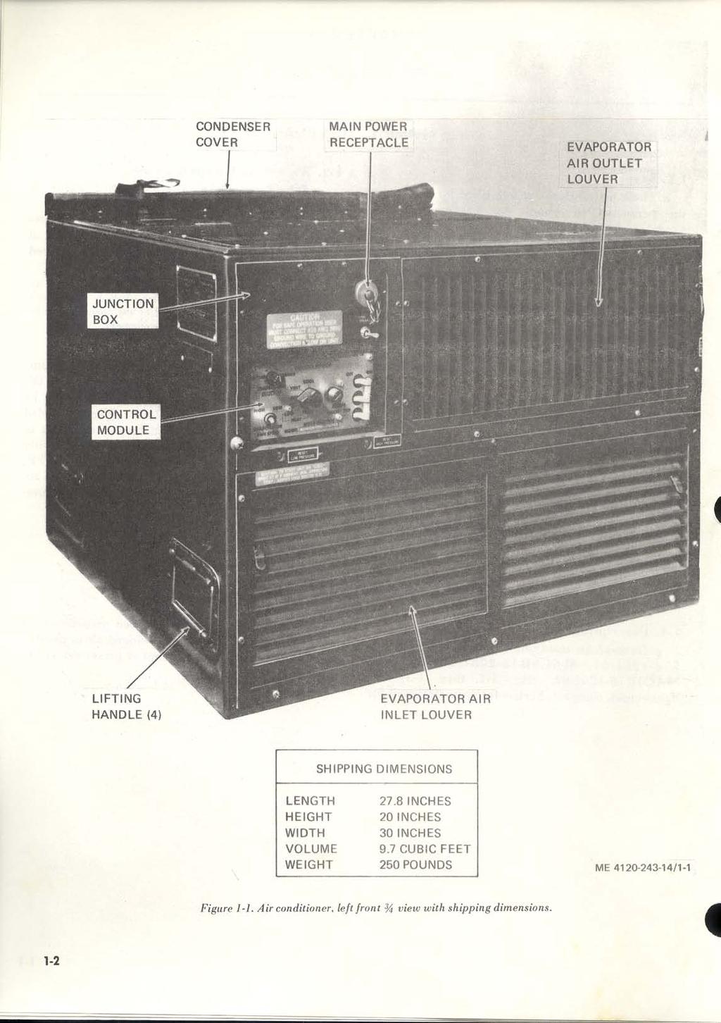
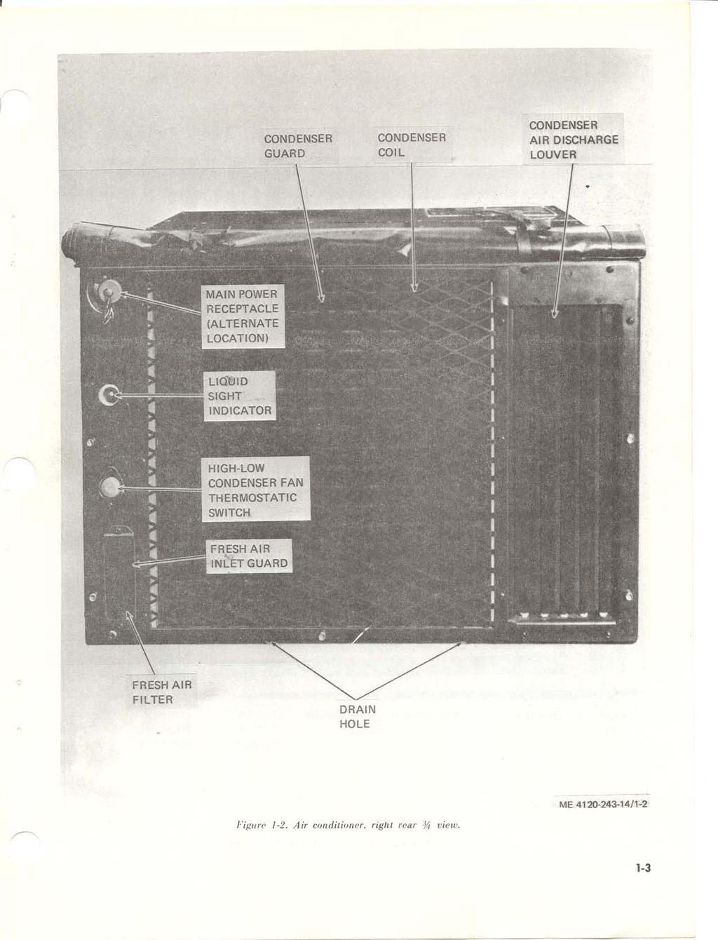
48 Number LIST OF ILLUSTRATIONS Title Page Air conditioner, left front 3/4 view with shipping dimensions Air conditioner, right rear 3/4view Air conditioner, top view, top covers removed Control system schematic diagram, 1 phase, 50/60 hertz, 230 volts Control system schematic diagram, 3 phase, 50/60 hertz, and 400 hertz, 208 volts Wiring diagram, 1 phase,50/60 hertz, 230 volts Wiring diagram, 3 phase, 50/60 hertz, 208 volts Wiring diagram, 3 phase, 400 hertz, 208 volts Base mounting holes Typical installation of air conditioner to enclosure Control and instruments (sheet 1 of 2) Controls and instruments (sheet 2 of 2) Starting instructions for cooling Operating instructions for cooling Starting instructions for heating Operating instructions for heating Operating instructions for ventilation Stripping instructions R. F. I. capacitors Evaporator air louvers and air filter Fresh air vent screen Louver blades push-on nuts Housing covers Evaporator drain tubing Vent damper control Vent damper Heater thermostatic switch Heater elements and support Evaporator fanand motor assembly Condenser fan and motor Condenser fan motor and mounting plate, exploded view Motor thermal protector housing Condenser fan motor thermostatic switch Fan motor capacitors Control module connector knob and bulb mounting Control module less cover Junction box, partially removed Junction box components, exploded view Transformer, rectifier, and pressure switches Compressor electrical connector and terminal box cover Compressor start capacitor and relay Compressor run capacitor Refrigerant flow diagram Compressor,removal and installation Evaporator coil, remova l and installation Condenser louver control, and actuator cylinder Condenser. air discharge louver assembly Condenser coil, removal and installation Charging valves and pressure switch connections Dehydrator, receiver and solenoid valves Thermal expansion valve Quench valve and pressure regulator valve Pressure regulator valves Accumulator Accumulator Discharge and evacuating refrigerant system Charging refrigerant system Solenoid valve, exploded view Fan motor, exploded view Control module, exploded view iii
49 CHAPTER 1 INTRODUCTION Section I. GENERAL 1-1. Scope a. These instructions are published for the use of the personnel to whom the Trane Company Models, MAC6H , MAC6H and MAC4H Air Conditioners are issued. Chapters 1 through 4 provide information on the operation, preventive maintenance services, and organizational maintenance of the equipment, accessories, components, and attachments. Chapters 5 and 6 provide information for direct and general support maintenance. Also included are descriptions of main units and their functions in relationship to other components. b. Appendix A contains a list of publications applicable to this manual. Appendix B contains the Maintenance Allocation Charts. Appendix C contains a list of Basic Issue Items authorized to operator of this equipment. The Organizational, Direct, and General Support Maintenance Repair Parts are listed and illustrated in TM P (when printed). c. Numbers in parentheses on illustrations indicate quantity Record and Report Forms a. DA Form 2258, Depreservation guide of Engineer Equipment. b. Maintenance forms, records, and reports which are to be used by maintenance personnel at all maintenance levels are listed in and prescribed by TM Note. Applicable forms, excluding Standard Form 46 (United States Government Motor Vehicle Operator s Identification Card) which is carried by the operator, will be kept in a canvas bag mounted on the equipment Reporting of Errors a. Report of errors, omissions, and recommendations for improving this publication by the individual user is encouraged. Reports should be submitted on DA Form 2028 (Recommended Changes to Publications) and forwarded direct to Commanding General, U. S. Army Mobility Equipment Command, ATTN: AMSME-MPP, 4300 Goodfellow Boulevard, St. Louis, Mo b. Report all equipment improvement recommendations as prescribed by TM Section II. DESCRIPTION AND DATA 1-4. Description cooling and heating air to a desired predetermined a. General. Air conditioners, Model MAC6HA18- range and circulating the conditioned air to provide , MAC6H , and heating or cooling of equipment or personnel within MAC4H , (fig. 1-1 thru 1-3) are the air conditioned area. lightweight, compact, horizontal units designed for 1-1
50
51
52
53 b. Evaporator Section. The evaporator section contains the evaporator coil, fan motor and fan, control module and junction box, air filter, heating elements and thermal expansion valve. When cooling, air in the evaporator section is forced over the evaporator coil by the evaporator fan which lowers the temperature of the air before it is distributed into the space to be conditioned. When heating, air is circulated over the heating elements and distributed by the evaporator fan. Evaporator fan speed is controlled by a selector switch located on control module. c. Condenser Section. The condenser section contains the hermetically sealed motor compressor, condenser coil, condenser fan and motor, service valves, filter dryer, equalize solenoid valve, liquid line solenoid valve, liquid quench valve, pressure regulator valves, electrical power connectors, and the necessary refrigerant. The compressor mechanically compresses refrigerant vapor to a condensing condition and discharges it into the condenser coil through the hot gas line. Outside air, drawn over the condenser coil surface by the condenser fan, condenses the refrigerant vapor to a liquid. The liquid then leaves the condensing coil and returns to the thermal valve through the liquid line. Condenser fan speed is controlled with a thermostatic switch located on rear of unit. At ambient temperature of 100 F(±5 F) or above the condenser fan speed will turn at high speed but at ambient temperature below 100 F (±5 F) the condenser fan will turn at low speed. Due to residual mass heat there will be a delayed reaction time for this to happen when ambient temperature drops below the 100 F changeover point Differences Between Models a. This manual covers Trane Model MAC6H , MA C6H , and MAC4H air conditioners. Each model is designed to operate on a different set of incoming power current characteristics. The electrical characteristics for each model are as follows : (1) MAC6H Single phase, 50/60 hertz, 230 volts. (2) MAC6H Three phase, 50 /60 hertz, 208 volts. (3) MAC4H Three phase, 400 hertz, 208 volts. b. Where instructions and descriptions apply only to specific models, the model numbers to which the description or instructions apply will be specified. If no model number is specified, the instructions or descriptions apply to all three models Identification and Tabulated Data a. Identification. Each air conditioner has one major identification plate mounted on the side of the unit. The plate specifies nomenclature, manufacturer, military part number, BTU / HR, phase, hertz, volts, serial number, contract number, and shipping weight. A manufacturers identification plate mounted just below that military plate contains the manufacturer s name and ad dress and the moodel and serial numbers. b. Tabulated Data.. (1) Air conditioner (Model MAC6H ). Nomenclature Air conditioner, horizontal, compact Manufacturer The Trane Company Capacity : Cooling ,000 BTU/HR Heating ,300~ BTU/HR Phase Hertz /60 Volts (2) Air conditioner (Model MAC6H ). Nomenclature Air conditioner, horizontal, compact Manufacturer The Trane Company Capacity: Cooling ,000 BTU / HR Heating ,300 BTU/HR Phase Hertz /60 Volts (3) Air conditioner (Model ). MAC4H Nomenclature Air conditioner. horizontal. compact Manufacturer The Trane Company Capacity: Cooling ,000 BTU / HR H e a t i n g BTU / HR Phase Hertz Volts (4) Condenser fan motor (B2) and/or evaporator fan motor (B3) (Model MAC6H ). Manufacturer IMC Magnetics Corp. Model FBC4620 (modified by marking E ) Volts Hertz /60 Phase Single RPM / 1725 Horsepower High Low Amperes High Low
54 Duty Continuous Motor drive Direct Thermal protector Automatic reset type opens at 145 C ± 5 C Rotation (facing shaft end) Counterclockwise (5) Condenser fan motor (B2) and/or evaporator fan motor (B3) (Model MA C6H ). Manufacturer IMC Magnetics Corp. Model FBT (modified by marking E6140-3) Volts Hertz /60 Phase RPM /1725 Horsepower... High Low Amperes High Low Duty Continuous Motor drive direct Thermal protector.. Automatic reset type High pens at120 C ±5 C Low pens at 150 C ±7 C Rotation (facing shaft end) Counterclockwise (6) Condenser fan motor and/or evaporator fan motor (Model MA C4H ). Manufacturer IMC Magentics Corp. Model... BT (modified by marking " E6140-4") Volts Hertz Phase...3 RPM /1800 Horsepower Hgh Low Amperes High Low Motor drive Direct Thermal protector Automatic reset type High Opens at 150 C ±5 C Law Opens at 150 C±5 C Rotation (facing shaft end) Counterclockwise (7) R.F.I. capacitor (C1). Type designation.. CK14AX103K Specification... MIL-C-11015/20A Type Fixed Dielectric.. Ceramic Capacitance pf ± 10 pf (8) R.F.I. capacitor (C2 or C6). Manufacturer Paktron Part number Paktron wa.056 Type Fixed Dielectric Mylar Capacitance mfd ± 10% Working voltage VDC (9) Condenser fan motor capacitor (C2) (MAC6H ). Manufacturer General Electric Part number 28 F1557G2 (modified by marking E ) (with protective boot 614A625P21) Type Fixed Dielectric Paper Capacitance 12.5 mf Volts AC (10) Evaporator fan motor capacitor (C3) (MAC6H ). Manufacturer General Electric Part number 28F1557G2 (modified by marking E6236-4") (with protective boot 614A625P21) Type, Fixed Dielectric Paper Capacitance mf Volts AC (11) Compressor motor starting capacitor (C4) (MAC6H ). Manufacturer... General Electric Part number F1109BA3 (modified by marking E6239") Type Fixed, aluminum electrolytic Capacitance mf ±10% Bleed resistor ,000 ohms ± 20%, 1 watt (12) Compressor motor run capacitor (C5) (MAC6H ). Manufacturer General Electric Part number F5013FB (modified by marking E6236-5") (with protective boot 614A625P21) Type Fixed Dielectric Paper Capacitance mf Volts AC O (13) Compressor circuit breaker (CB1) (MAC6H ). Manufacturer Heinemann Electric Part number ja2z21-3 (modified by marking E6206-3") Type DPST series trip with mechanically actuated auxiliary switch (14) Compressor circuit breaker (CB1) (MAC6H ). Manufacturer Heinemann Electric Part number JA3Z18-3. (modified by marking " E6205.3") Type PST. series trip with mechanically actuated auxiliary Switch 1-6
55 (15) Compressor circuit breaker (CB1) (MAC4H ). Manufacturer Heinemann Electric Part number JA3Z18-4 (modified by marking E ) Type PST, series trip with mechanically actuated auxiliary switch (16) Control circuit breaker (CB2) (MAC6H and (MAC6H ). Manufacturer Texas Instruments, Inc. Part number M (modified by marking E ) Type SPST, series trip (17) Control circuit breaker (CB2) (MAC4H ). Manufacturer Texas instruments, Inc. Part number m (modified by marking E ) Type SPST, series trip (18) Rectifier (CR1). Manufacturer Motorola Semiconductor Products, Inc. Part number MDA952-3 (modified by marking E6223 ) (19) Heater element (HR1 through HR6) (MAC6H ). Manufacturer..... Part number Sheath Element Volts Watts Hotwatt Inc. 13E (modified by marking E ) Nickel-iron-chromium tubular type Nickel-chromium alloy (20) Heater element (HR1) through HR6) (MAC6H and MAC4H ). Manufacturer Hotwatt Inc. Part number 13E (modified by marking E ) Sheath.... Element Volts Watts Alternate Type Time delay Nickel-iron-chromium tubular type Nickel-chromium (21) Time delay relay (K 1). Manufacturer Part number alloy. E. V. Naybor Laboratories, Inc. TQ1D25 (modified by marking E6182 ) HI-G Inc. Part No (modified by marking) SPDT 25 ±6 seconds (22) Heater relay (K2). Part number MS24192D1 Type PST, Normally open Volts VDC: (23) Compressor motor relay (K3). Part number... MS24192D1 Type PST, Normally open Volts VDC (24) Condenser fan relay (K4). Manufacturer....../ /... Potter and Brumfield Part number KA4619 (modified. by marking E6184 ) Type PDT, armature type Coil voltage vdc (25) Compressor start relay (K5) (MAC6H ). Manufacturer Essex Wire Corp. Part number S (modified by marking E6240 ) Type... SPST, armature type, normally closed (26) Phase sequence relay (K5) (MAC6H ). Manufacturer HI-G Inc. Part number S421 (modified by marking E ) Type SPDT Hertz /60 Phase Voltage VAC (27) Phase sequence relay (K5) (MAC4H ). Manufacturer HI-G. Inc. Part number S428 (modified by marking E ) Type SPDT Hertz Phase Voltage VAC (28) Solenoid valves (L1 and L2). Manufacturer Jackes-Evans Mfg. Co. Part number OB2S3 (modified by marking E6158") Type Pilot operated diaphragm type, normally open (when not energized) Volts DC (29) Rotary selector switch (S1). Manufacturer Cutler Hammer Part number K261 (modified by marking E6201 ) Type PDT, 4 switch wafers Number of switch positions (30) Toggle switch (S2). Manufacturer Cutler Hammer Part number K1462 (modified by marking E6200") Type PDT, slow make, slow break contacts 1-7
56 (31) Temperature selector switch (S3). Manufacturer Penn Controls, Inc. Part number A19AGF23 (modified by marking E ) Type SPDT Temperature range F to 90 F (32) High pressure switch (S4). Manufacturer Penn Controls, Inc. Part number ap40an2301 (modified by marking E6215-3") Type SPST, normally closed with trip free manual reset Pressure setting 445 ±10 psig (33) Low pressure switch (S5). Manufacturer Penn Controls, Inc. Part number AP10AN2308 (modified by marking E6215-1") Type SPST, normally closed with trip free manual reset Pressure setting ± 5 psig (34) Heater thermostatic switch (S6). Manufacturer Therm-O-Disc, Inc. Part number HLAS4947 (modified by marking E6224 ) Type DPST. normally closed, bimentallic Reset Automatic Contacts open (temp. rise) ±5 F Contacts close (temp. drop) ±10 F (35) Condenser fan relay thermostatic switch (S7). Manufacturer Therm-O-Disc, Inc. Part number T22 (modified by marking E6217" and changing mounting holes to slots) Type SPST, normally open, nonadjustable bimetallic disc Contacts close (temp. rise) ±5 F (36) Transformer (T1). Manufacturer Signal Transformer Co., Inc. Part number (modified by marking E6214 and changing mounting slots to holes) Rating: Input VAC, 120 watts, 50 to 500 hertz Output VAC, 4 amps (37) Compressor (MAC6H ). Manufacturer... Whirlpool Corporation Part number WHP622-H (modified by marking E ) Oil charge ounces Volts Cycles /60 Phase Weight (with oil) 55 pounds (38) Compressor (MAC6H ). Manufacturer Whirlpool Corporation Model WHP-622H (modified by marking 13211E ) Oil charge 20.5 ounces Volts Cycles /60 Phase, Weight (with oil1) pounds (39) Compressor (MAC4H ). Manufacturer Whirlpool Corporation Model WHP-422H (modified by marking E3793-1") Oil charge 20.5 ounces Volts Hertz Phase Weight (with oil pounds (40) Thermal expansion value. Manufacturer Alco. Controls Corp. Part number HNE2HW 100-6A (modified by marking E6160-2") Inlet /8 ODF Outlet /2 ODF Cap tube length " Norminal capacity 2 Ton Superheat (factory set) F ±1/2 at a 32 F bath temperature (41) Liquid quench valve. Manufacturer Alco Controls Corp. Part number HN3/4CW16A (modified by marking E ) Inlet /4ODF Outlet /8ODF Cap tube length " Nominal capacity /4 Ton Superheat (factory set) F ±1/2 at a 32 F bath temperature (42) Refrigerant service valves. Manufacturer Henry Valve Co. Part number F503A VaIve stem Hex socket for closing (43) Pressure regulator valve. opening and Manufacturer Controls Co. of America Model number A Part number (modified by marking E6171 ) Adjustment range to 80 psig Setting psig (44) Liquid sight indicator. Manufacturer Sporlan Valve Co. Part number SA12S (modified by marking E6155 ) 1-8
57 Dehydrator. M a n u f a c t u r e r Alto Valve Co. Part number ADKOSZ (modified by marking ) -Pyp~ Sealed-non-refillable (46) Actuator cylinder assembly. Mannfacturer Part number Stroke Robert Shaw Controls Co. Poll-12 (modified by marking E6128 and changing cable attachment plate).052 in. Full stroke pressure ( n o l o a d ) 240 rf: 20 psig Pressure to start s t r o k e 165 rt 15 psig (47) Dimensions and weights. Length 27.8 in. Height 20 in. Width in. Weight 250 lbs Diagrams a. Control System Schematic Diagrams.Refer to figure l-4 and 1-5 for schematic wiring diagrams. Figure 1-4. Control system schematic diagram, 1 phase, 50/60 hertz, 230 volts. (Located in back of manual) Figure l-5. Control system schematic diagram, 3phase, 50, 60 hertz and 400 hertz, 208 volts. (Located in back of manual) b. Wiring Diagrams.Refer to figures l-6 through l-8 for wiring diagrams. Figure 1-6. Wiring diagram, 1 phase, 50 / 60 hertz, 230 volts. (Located in back of manual) Figure l-7. Wiring diagram, 3 phase. SO/ 60 hertz, 208 volts. (Located in back of manual) Figure 1-8. Wiring diagram, 3 phase, 400 hertz, 208 volts, (Located in back of manual)
58 CHAPTER 2 INSTALLATION AND OPERATION INSTRUCTIONS Section I. SERVICE UPON RECEIPT OF EQUIPMENT 2-1. Unloading Equipment The total weight of the air conditioner is 250 pounds. Use a hand truck or forklift of at least 300 pounds capacity to unload the unit. Keep unit upright during the unloading operation Unpacking Equipment Move the unit as near to the site of installation as possible. Remove crating hardware and metal straps, being careful not to damage the unit with the tools used for uncrating Inspecting and Servicing Equipment a. Inspection. Inspect the entire air conditioner for signs of damage, missing or loose hardware, and any defects that may have been incurred during shipment. Make a thorough check to see that all wiring, lines, and tubing are secure; and pay particular attention to the evaporator and condenser coils and main power receptacle connectors. Be sure that visible wiring and insulation is not frayed or broken. Check the evaporator and condenser fan motors. Report all damage and defects to organizational maintenance. b. Servicing. Perform the daily preventive maintenance services listed in paragraph 3-6. Be sure all hardware is securely in place Installation a. General. The air conditioner is shipped, assembled and ready for operation. It contains a full charge of refrigerant and compressor oil. Install the unit on a firm, level surface to allow proper condensate drainage. Place it so that the control panel and condenser and evaporator louvers are accessible to the operator and to maintenance personnel. Be sure there are no obstructions in front on any air intake or discharge louvers or other openings that may cause insufficient flow of air into or out of the air conditioner. If the unit is van mounted, report any such obstructions to organizational maintenance. b. Mounting. Base mounting hole dimensions are shown on figure 2-1. The resilient mount parts shown in figure 2-2 are shipped with the air conditioner. 2-1
59 2-2 Figure 2-2. Typical installation on air conditioner to enclosure.
60 Caution: For safe operation, connect a No. d. Air Ducts. Connect air ducts contingent to site 10 AWG (min.) ground wire to ground con- of installation. Mount air filter in duct work if an nection. evaporator return air duct is required. c. Connections. Connect the main power cable. Note. Operation without filtration will clog coils. Section II. MOVEMENT TO A NEW WORKSITE 2-5. Dismantling for Movement e. If the air conditioner is to be moved over a long a. Disconnect main power cable. distance, recrate it by reversing the unpacking b. Disconnect drain lines from the outlets. procedures. See paragraph 2-2. c. Disconnect any air ducts and install the 2-6. Reinstallation After Movement evaporator air discharge grille and air return grille. After movement, follow the procedures in d. Remove the unit from the mounting surface. paragraph 2-4 to reinstall the air conditioner. Section III. CONTROLS AND INSTRUMENTS 2-7. General 2-8. Controls and Instruments This section describes, locates, and illustrates the The location and the function of the controls and various controls and provides the operator crew instruments are illustrated in figure 2-3. sufficient information to insure proper operation of the air conditioner. 2-3

61 2-4 Figure 2-3 Controls and Instruments (sheet 1 of 2)

62 Figure 2-3. Controls and Instruments (sheet 2 of 2) Section IV. OPERATION UNDER USUAL CONDITIONS 2-9. General different problem, the operator may have to vary a. The instructions in this section are published the given procedure to fit the condition. for the information and guidance of the personnel Starting and Operating Instructions responsible for the operation of the air conditioner. a. Preparation for Starting. b. The operator must know how to perform every (1) Perform the daily preventive maintenance operation of which the air conditioner is capable. service (para 3-6). This section gives instructions on starting and (2) Connect the main power cable. stopping the air conditioner, and detailed operating (3) Check drain holes to insure that they are instructions. Since nearly every condition presents a open. 2-5
63 (4) Be sure the unit is firmly secured. (5) Roll up condenser cover and tie at top of air conditioner to clear condenser opening. b. Starting Instruction for Cooling. Start the air conditioner for cooling as shown in figure 2-4. c. Operating Instructions for Cooling. Operate the air conditioner for cooling as shown in figure 2-5. d. Starting Instructions for Heating. Starting the air conditioner for heating is shown in figure 2-6. e. Operating Instructions for Heating. Operate the air conditioner for heating as shown in figure 2-7. f. Operating Instructions for Ventilation. Operate the air conditioner for ventilation as shown in figure
. TURN ON CONTROL CIRCUIT BREAKER. TURN MODE SELECTOR SWITCH TO VENTILATE AND ALLOW FAN TO REACH FULL SPEED, THEN TURN TO COOL.")
64 STEP 1. STEP 2 STEP3. STEP4. STEP 5. STEP 6. BE SURE CONDENSER COVER IS ROLLED UP. LIFT TABS.AND OPEN INTAKE LOUVERS. TURN FRESH AIR VENT CONTROL ACTUATOR TO CLOSE DAMPER DOOR. TURN TEMPERATURE SELECTOR SWITCH TO FURTHEST CLOCKWISE POSITION (WARMER). TURN ON CONTROL CIRCUIT BREAKER. TURN MODE SELECTOR SWITCH TO VENTILATE AND ALLOW FAN TO REACH FULL SPEED, THEN TURN TO COOL. ME /2-4 Figure 2-4. Starting instruction for cooling. 2-7

65 2-8 Figure 2-5. Operating instructions for cooling.

66 Figure 2-6. Starting in instructions for heating. 2-9

67 2-10 Figure 2-7. Operating instructions for heating.

68 Figure 2-8. Operating instructions for ventilation. 2-11

69 2-11. Stopping Instructions b. Perform the daily preventive maintenance a. Stop the air conditioner as shown by figure 2- service (para 3-6). 9. NOTE: IF SHUTDOWN IS FOR AN EXTENDED PERIOD, COVER EVAPORATOR AND CONDENSER LOUVERS AND DISCONNECT POWER CABLE. STEP 1. STEP 2. TURN MODE SELECTOR SWITCH TO OFF. CLOSE INTAKE LOWERS. STEP 3. TURN ACTUATOR TO CLOSE FRESH AIR VENT DAMPER. ME / Figure 2-9. Stopping instructions.
70 Section V. OPERATION UNDER UNUSUAL CONDITIONS Operation in Extreme Cold Caution: To start unit on Cool mode at 0 F ambient (min. operating temp.), jumper LPCO switch (S-5). a. General. The air conditioner is designed to operate on the heating cycle in ambient temperatures as low as minus 50 F (Fahrenheit) and on cooling cycle with 0 F air entering the condenser and 70 F air entering the evaporator. b. Before Operation. Before starting on cooling cycle, be sure cover is removed from condenser air intake and discharge Clear all ice and snow from openings. Be sure all dampers are in operating conditions. c. After Operation. Install cover over condenser air intake and discharge openings. Caution: Do not disturb wiring during cold weather unless absolutely necessary. Cold temperatures make wiring and insulation brittle and easily broken Operation in Extreme Heat a. General. The air conditioner is designed to operate satisfactorily at temperatures up to plus 120 F. If unit is operated at condenser inlet temperatures higher than 120 F, the cooling capacity will be lowered and long periods of operation at extended temperatures may cause condenser or condenser fan motor to overheat and trip their internal overload switches or the high pressure cut out switch will shut the unit off. b. Filters. To maintain the highest capacity of the unit, the return air filter and fresh air screen should be cleaned weekly or more often if necessary. Dirty filters reduce the flow of air across the evaporator coil, thereby reducing the capacity of the air conditioner. c. Guards and Louvers. Keep all guards and louvers clean and free of any obstructions to maintain full air flow through the air conditioner. d. Coils. Clean evaporator and condenser coils as frequently as necessary to prevent dirt or other matter from obstructing the air flow Operation in Dusty or Sandy Areas a. Protection. Shield the air conditioner from dust as much as possible. Take advantage of any natural barriers which offer protection. b. Cleaning. Keep the air conditioner as clean as possible. Pay particular attention to the louvers, filters, coils electrical components and grilles. Use compressed air, if available, to aid in cleaning. c. Air Filters and Coils. (1) Under extremely dusty or sandy conditions, the louvers. filters, coils. electrical components and grilles must be serviced more often. Note. Never operate the unit without having the air filters in place. (2 ) The condenser coil is subjected to ambient air. Therefore, it requires cleaning more often than the evaporator coil Operation Under Rainy or Humid Conditions Take special precautions to keep equipment dry. If installed outdoors, cover the equipment with a waterproof cover when it is not in use. Remove cover during the dry periods. Take all necessary precautions to keep electrical components free from moisture. Caution: Make sure power is disconnected from air conditioner before touching any wiring or other electrical parts Operation in Salt Water Areas a. General. Wash the exterior and condenser section of the unit, particularly condenser air discharge louver control mechanism. With clean fresh water at frequent intervals. Be careful not to damage electrical system with water. Special attention must be given to prevent rust and corrosion. Warning: Disconnect power source prior to washing the air conditioner. b. Painting. Paint all exposed areas where paint has cracked, peeled, or blistered or report condition to organizational maintenance. Coat all exposed areas of polished metal with a light coat of grease. 2-13
71 CHAPTER 3 OPERATOR/CREW MAINTENANCE INSTRUCTIONS Section I. BASIC ISSUE ITEMS 3-1. Basic Issue Tools and Equipment Tools, equipment, and repair parts issued with or authorized for the air conditioner are listed in the basic issue items list, appendix C Special Tools and Equipment No special tools or equipment are required by the operator/crew for maintenance of the air conditioner. Section II. LUBRICATION 3-3. Fan Motors 3-4. Compressor The evaporator fan and condenser fan motors are The compressor and compressor motor are fully permanently lubricated by the manufacturer and lubricated by the manufacturer and require no require no additional lubrication. additional lubrication. Section III. PREVENTIVE MAINTENANCE CHECKS AND SERVICES 3-5. General To insure that the air conditioner is ready for operation at all times, it must be inspected systematically so that defects may be discovered and corrected before they result in serious damage or failure. The necessary preventive maintenance services to be performed are listed and described in paragraph 3-6. The item numbers indicate the sequence of minimum inspection requirements. Defects discovered during operation of the unit will be noted for future correction to be made as soon as operation of the unit has ceased. Stop operation immediately if a deficiency is noted during operation which would damage the equipment if operation were continued. All deficiencies and shortcomings will be recorded, together with the corrective action taken, on DA Form 2404 (Equipment Inspection and Maintenance Worksheet) at the earliest possible opportunity Daily Preventive Maintenance Services This paragraph contains a tabulated listing of preventive maintenance services which must be performed by the operator. The item numbers are listed consecutively and indicate the sequence of minimum requirements. Refer to table 3-1 for the daily preventive maintenance services. 3-1
72 Before operation Interval and sequence number During operation Operator s Maintenance Category After operation Table 3-1. Preventive Maintenance Checks and Services Item to be inspected Evaporator outlet louver. Evaporator inlet louver. Condenser cover. Fresh air inlet Drains Condenser louver. Condenser guard. Controls Main power receptacle connector Liquid sight indicator Air conditioner operation. Condenser cover. Procedure Remove obstructions. Clean louvers. Tighten mounting screws. Remove obstructions. Clean louvers. Check for ease of operation. Tighten mounting screws. With cover rolled up for operation check securing ties for damage. Inspect for obstructions and insecure mounting. Remove obstructions clean and tighten loose mounting screws. Inspect drains for obstructions. Remove obstructions. Check for insecure mounting and damaged louvers. Remove obstructions and clean guard. Check for visual damage. Check operation of damper control. Check for secure power connection. Tighten if necessary. Check for moisture and low refrigerant charge. Yellow indicates moisture bubbles or milky appearance indicates low charge. Check for abnormal operation, vibration, unusual noise, failure to respond to controls. Check for damaged fasteners. Paragraph referece paragraph 3-10 paragraph 3-10 paragraph 3-10 paragraph 3-11 paragraph 3-10 paragraph 3-10 paragraph 2-8 paragraph
73 Section IV. TROUBLESHOOTING 3-7. General listed in table 3-2. The first column shows the This section contains information that is useful in apparent trouble or symptom, the second column diagnosing and correcting troubles which cause contains the probable cause, and the correcting unsatisfactory operation or failure of the air action is listed in the third column. Remedies that conditioner. are beyond the scope of the operator must be reported to organizational maintenance Operator s Troubleshooting Chart Troubleshooting procedures for operator/crew are Malfunction 1. Air conditioner fails to operate. 2. Insufficient cooling. 3. No heat or low capacity heat. Table 3-2. Troubleshooting Chart Probable Cause a. Main power cable disconnected. b. Control or compressor circuit breaker in OFF position. c. Mode selector switch in OFF position. a. Mode selector switch improperly positioned. b. Temperature selector switch set incorrectly. c. Insufficient air passing over evaporator coil. d. Too much outside air entering unit. e. Insufficient refrigerant in system. f. Evaporator fan speed switch set at low speed. g. Insufficient air passing through condenser coil. a. Mode selector switch improperly set. b. Temperature selector switch set incorrectly. c. Insufficient air movement over heaters. Corrective Action a. Connect power cable to receptacle (fig. 2-3, sheet 1). b. Reset circuit breaker (fig sheet 1). c. Turn selector switch knob to desired operation (fig. 2-3, sheet 1). a. Set switch to COOL (fig. 2-.5). b. Adjust setting to COOLER (fig. 2-5). c. Open evaporator inlet louvers (fig. 2-4). Remove any obstructions from evaporator inlet and outlet louver (para 3-10). d. Close or adjust damper door (fig. 2-3, sheet 1). e. Check liquid sight indicator (para 3-12). f. Reset switch to high speed (fig. 3-2, sheet 1). g. Remove any obsturctions for condenser fan inlet and outlet (para 3-10). Make sure louvers are open (fig. 2-3, sheet 3). a. Set switch to LOW HEAT OR HIGH HEAT (fig. 2-3, sheet 1). b. Reset switch (fig. 2-3, sheet 1). c. Remove any Obstructions from evaporator air intake and discharge louvers (para 3-10). Make sure intake louvers are open (fig sheet 3). Section V. OPERATOR S MAINTENANCE OF AIR CONDITIONER 3-9. General Liquid Sight Indicator This section contains maintenance procedures for Wipe refrigerant liquid sight indicator glass with a the operator of the air conditioner. soft clean cloth. Set controls at cool-cooler and Louvers, Condenser Guard and Fresh Air operate unit for 15 minutes before observation. Screen Yellow appearance indicates moisture in system and bubbles or milky flow indicate low refrigerant Remove any obstructions. Brush off loose dirt and charge. Report presence of these conditions to wipe clean. direct support maintenance Drains Clean out drain openings and remove any- obstructions. 3-3
74 CHAPTER 4 ORGANIZATIONAL MAINTENANCE INSTRUCTIONS Section I. SERVICE UPON RECEIPT OF MATERIAL 4-1. General ponents is to be performed by organizational Instructions for unloading, unpacking and in- maintenance personnel. If other than new stalling the air conditioner are covered in equipment has been received, a thorough inspection paragraphs 2-1, 2-2 and 2-4. is to be performed. b. Servicing. Remove and inspect return air filter 4-2. Inspecting and Servicing Equipment and fresh air screen and service filter and screen if a. Inspection. General inspection of the necessary. equipment is covered in paragraph 2-3. If possible 4-3. Installation dam age has occured, requiring removal of covers or other components not authorized for removal by the operator, further inspection of internal com- Check air conditioner for proper installation. If auxiliary power connection is to be used, change leads as shown on wiring diagram. Section II. MOVEMENT TO A NEW WORKSITE 4-4. Dismantling for Movement 4-5. Reinstallation After Movement Refer to paragraph 2-5. Refer to paragraphs 2-6 and 4-3. Section III. REPAIR PARTS, SPECIAL TOOLS, AND EQUIPMENT 4-6. Tools and Equipment 4-8. Maintenance Repair Parts Refer to appendix C for tools, equipment and Repair parts and equipment are listed and repair parts issued with the air conditioner. illustrated in the repair parts and special tool list 4-7. Special Tools and Equipment covering organizational maintenance for this equipment. (TM P) (when printed). No special tools or equipment are required for maintenance of the air conditioner. Section IV. PREVENTIVE MAINTENANCE CHECKS AND SERVICES 4-9. General Periodic maintenance checks are required by organizational maintenance personnel to check the performance of daily preventive maintenance services. Additional periodic maintenance services are required that are beyond the scope of the operator s maintenance Quarterly Preventive Maintenance Service a. This paragraph contains a tabulated listing of preventive maintenance services which must be performed by organizational maintenance personnel at quarteriy intervals. A quarterly interval is equal to three calendar months, or 250 hours of operation, whichever occurs first. b. The item numbers are listed consecutively and indicate the sequence of inspection and minimum requirements. Refer to table 4-1 for quarterly preventive maintenance services. c. Some services are required at a shorter interval and are so noted. Service intervals should be shorted under extreme or unusual conditions. 4-1
75 1 *2 3 * Table 4-1. Preventive Maintenance Checks and Services Organizational Maintenance Category Monthly Schedule (or quarterly) Item to be inspected Evaporator inlet and discharge louvers Air filter Condenser guard Fresh air screen Evaporator Coil Condenser coil Condenser cover Housing covers Fans Heaters Controls and instruments Junction box components Wiring and electrical components Liquid sight indicator refrigeration system Procedures Clean, inspect for damage. Replace if necessary. Inspect and service or replace if necessary. Inspect and clean. Replace if damaged. Inspect and clean or replace as necessary. Clean and inspect. Clean and inspect. Inspect, clean and repair or replace if damaged. Repair or replace damaged covers. Check fans for damage. Check motors for evidence of over heating. Replace damaged fans and motors. Check for breaks in wiring and insulation. Tighten loose connections. Check for damage to any controls in control module. Replace defective parts or control module. Check for defective relays and circuit breaker. Check for damaged or frayed wiring. Check for defective electrical components. Repair or replace defective wiring. Replace defective electrical components. Check for damage. Check compressor, valves, and piping for damage. Report damage to direct support maintenance. Paragraph reference paragraph 4-18 paragraph 4-17 paragraph 4-20 paragraph 4-19 paragraph 4-24 paragraph 4-23 paragraph 4-21 paragraph 4-21 paragraphs 4-38, 4-39, and 4-40 paragraph 4-35 paragraphs 4-44, thru 4-48 paragraphs 4-49 thru 4-54 paragraph 4-33 paragraph 4-63 l Perform check and service weekly. 4-2
76 Section V. TROUBLESHOOTING General This section contains troubleshooting instructions for the isolation of causes of common troubles that may occur during operation and also contains the possible remedies to correct the trouble Organizational Troubleshooting Chart a. General. Troubleshooting procedures for organizational maintenance personnel are listed in table 4-2. The first column shows the apparent trouble or symptom. The second column contains the probable cause. The third column lists the corrective action to be taken. Remedies that are beyond the scope of organizational maintenance must be reported to direct support maintenance personnel. Additional procedures are listed in paragraph b and c below. b. Control Circuit. The cause for a system s failure to operate can be greatly narrowed if the control which caused the failure can be isolated. It is the function of safety devices to open the circuit under certain conditions; therefore, additional checking may be required to determine whether the safety device is open because it is defective or is performing its designed function. The following steps contain instructions for checking the control circuit. (1) Disconnect power from air conditioner. (2) Test the continuity across each control in the affected circuit with a test lamp or ohmmeter if available using schematic diagrams as a guide. Check wiring diagrams for connections. (3) Replace defective parts. c. Safety Devices. When testing the control circuit and other equipment, take into consideration the fact that open safety devices may not be defective. It may be normal for the device to be open under the existing conditions or it may indicate trouble elsewhere in the air conditioner. Malfunction 1. Air conditioner fails to operate. 2. Insufficient cooling. Table 4-2. Troubleshooting Chart Probable Cause a. Main power cable disconnected. b. Main power receptacle connector defective. c. Loose electrical connections. d. Rotary selector switch improperly adjusted or defective. e. Control or compresser circuit breaker in OFF position or defective. f. Defective phase, sensing relay. g. Defective control circuit transformer. h. Defective control circuit rectifier. a. Mode selector switch improperly positioned. b. Insufficient refrigerant charge. c. Condenser coil dirty. d. Evaporator return air filter dirty. e. Temperature selector switch set incorrectly or defective. f. Fresh air damper control set incorrectly or incorrectly adjusted. g. Defective compressor. h. Evaporator outlet louver bent or stuck in closed position. i. Evaporator fan motot worn or defective. j. Evaporator fan loose or defective. k. Evaporator fan motor thermal protector defective. Corrective Action a. Connect cable. b. Replace connector (para 4-33). c. Tighten connections. d. Turn selector switch to COOL" or VENTILATE". Replace a defective switch (para 4-44 through 4-48). e. Reset circuit breaker(s) or replace (para 4-44 thru 4-48 or para 4-50 thru 4-54). f. Replace defective phase sensing relay (para 4-50 thru 4-.54). g. Replace defective transformer (para 4-56). h. Replace defective rectifier (para 4-57). a. Set switch to COOL". b. Report condition to direct support maintenance. c. Clean coil (para 4-23). d. Clean filter (para 4-17). e. Adjust setting or replace switch (para 4-44 thru 4-48). f. Check setting of Control. Adjust fresh air damper control (para 4-27). g. Report condition to general support maintenance. h. Repair or replace louver (para 4-18). i. Report deficiency to direct support maintenance or replace motor (para 4-38 and 4-40). j. Tighten or replace fan. k. Replace thermal protector (para 4-39). 4-3
77 Malfunction 3. Evaporator or condenser fan fails to operate. 4. Compressor will not start. 5. Compressor starts but goes out on overload. Table 4-2. Troubleshooting Chart Continued Probable Cause a. Main power cable disconnected. b. Defective fan motor. c. Evaporator or condenser fan defective or binding. d. Defective condenser motor thermal protector. e. Defective evaporator fan motor thermal protector. f. Defective receptacle or plug connectors. g. Defective high-low condenser fan thermostatic switch. h. Defective condenser fan relay. i. Defective evaporator fan speed control switch. j. Mode selector switch improperly adjusted or defective. a. Compressor or control circuit breakers or selector switch improperly set. b. Contacts of high or low pressure cutout switch open. c. Loose electrical connections or faulty wiring. d. Open control circuit. e. Defective circuit breaker. f. Defective control transformer. g. Defective rectifier. h. Defective time delay relay. i. Defective compressor relay. j. Defective starting relay or capacitor (single phase compressor). k. Defective phase sequence relay (three phase compressor). l. Defective or tripped compressor internal temperature overload switch. m. Defective compressor motor. a. Condenser fan motor failure. b. High head pressure. c. Defective or tripped compressor internal temperature overload switch. d. Improperly adjusted or defective refrigerant control valves. Corrective Action a. Connect cable. b. Replace motor (para 4-32 and 4-40). c. Relieve binding or replace fan (para 4-38 and 4-40). d. Replace thermal protector (para 4-39). e. Replace thermal protector (para 4-39). f. Replace connectors or receptacles (para 4-33). g. Replace thermostatic switch (para 4-41). h. Replace defective relay (para 4-50 thru 4-54). i. Replace defective switch (para 4-44 thru 4-48). j. Replace a defective switch (para 4-44 thru 4-48). a. Reset controls properly. b. Reset pressure switches. Report deficiency to direct support maintenance if condition continues. c. Tighten loose connections. Repair wiring if necessary. d. Make continuity check of circuit (para 4-12). e. Replace defective control or compresser circuit breaker (para 4-44 thru 4-48 or para 4-50 thru 4-54). f. Replace defective transformer (para 4-56). g. Replace defective rectifier (para 4-57). h. Replace defective relay (para 4-50 thru 4-54). i. Replace defective relay (para 4-50 thru 4-54). j. Replace defective capacitor or relay (para 4-61). k. Replace defective relay (para 4-50 thru 4-54). l. Allow unit to cool. Report deficiency to direct support maintenance if condition continues. m. Check and report deficiency to general support maintenance if motor is defective. a. Replace defective motor (para 4-38 and 4-40). b. Clean condenser coil and louvers. Check fan for proper operation. c. Allow unit to cool. Report deficiency to direct support maintenance if condition continues. d. Report condition to direct support maintenance. 4-4
78 Malfunction 6. Evaporator air output volume low. 7. Condenser air output volume low. 8. Air conditioner fails to heat. 9. Excessive noise. Table 1-2. Troubleshooting Chart Continued Probable Cause c. Evaporate: fan speed switch set at low speed. a. Dirty or damaged filter or louvers. b. Iced or dirty evaporator coil. c. Defective evaporator fan. d. Defective fan motor. e. Evaporator fan speed switch set at low speed. a. Dirty condenser coil or guard. b. Defective HIGH-LOW condenser fan thermostatic switch. c. Defective condenser fan. d. Defective fan motor. e. Air outlet louvers stuck in closed position. a. Selector switch improperly adjusted. b. Temperature control switch set incorrectly. c. Dirty evaporator return air filter. d. Defective evaporator fan motor. e. Defective temperature selector switch or mode selector switch. f. Defective heaters or wiring. g. Defective heater relay. h. Defective heater high temperature cutout thermostatic switch. a. Evaporator or condenser fan vibrating. b. Evaporator or condenser fan motor worn or defective. c. Compressor knocks or clatters. Corrective Action d. Reset switch to high speed. a. Clean or replace filter (para 4-17). Clean or replace louvers as required (para 4-18). b. De-ice and clean coil (para 4-24). c. Replace fan. d. Replace motor (para 4-38 and 4-40). e. Reset switch to HIGH speed. a. Clean coil and guard (para 4-23). b. Replace switch (para 4-41). c. Replace fan. d. Replace motor (para 4-38 and 4-40). e. Free louvers and control cables. Adjust control or refer to direct support maintenance if actuating cylinder isnot functioning properly. a. Reset selector switch to LO-Heat or HI-heat (para 2-10). b. Reset switch (para 2-10). c. Clean filter (para 4-17). d. Replace motor (para 4-38 and 4-40). e. Replace defective switch (para 4-44 thru 4-48). f. Tighten connections and repair damaged wiring. Replace defective heaters (para 4-35). g. Replace defective relay (para 4-50 thru 4-54). h. Replace defective thermostatic switch (para 4-34). a. Tighten fans on shafts. Tighten all mounting screws. b. Replace worn or defective motor (para 4-38 and 4-40). c. Stop air conditioner and report condition to direct support maintenance. Section VI. RADIO INTERFERENCE SUPPRESSION General Methods Used to Attain Proper Suppression Essentially, suppression is attained by providing a low resistance path to ground for the stray currents. Methods used include shielding ignition and high frequency wires, grounding the frame with banding straps and using capacitors and resistors Interference Suppression Components The control module, junction box and electrical system components are grounded to the housing. The housing is connected to a ground wire in. power supply. Capacitors (fig. 4-1) are located across the rectifier terminals. Grommets are inserted in the heat support bracket to isolate heating elements from bracket to prevent metal to metal contact and scraping during expansion and contraction of heating elements. Power inlet cover chains are encased in shrink type tubing to prevent rattling of chain links Replacement of Capacitor a. Removal. (1) Remove front top cover of air conditioner. 4-5

79 (2) Disconnect capacitor (fig. 4-1) from terminals 1 and 3 or 2 and 4 of rectifier. b. Insta llation. Connect new capacitor across terminals 1 and 3 or 2 and 4 of rectifier as required and install from top cover. Figure 4-1. R.F.I. capacitors. Section VII. COVERS, LOUVERS, AND FILTERS General covered in separate paragraphs in this section. This This section covers the evaporator louvers, return unit was designed for use with CBR. air filter, condenser guard, condenser louvers, fresh Servicing Return Air Filter air screen, and the top covers of the housing. These a. General. The return air filter (fig. 4-2) parts must be serviced regularly or removed mounted in clips on the inner side of the inlet frequently to gain access to other parts of the air louver, filters the air returning to the air conditioner conditioner. For ease of reference these parts are from the conditioned air. 4-6

80 Figure 4-2. Evaporator air louvers and air filter. 4-7
81 b. Removal. Remove eight screws and lock washers and remove evaporator air inlet louver (fig. 4-2). Slide return air filter from retaining clips on louver. c. Cleaning and Inspection. Clean and inspect air filter as follows: (1) W ash filter in detergent or cleaning solvent (Fed. Spec. P-D-680). Dry thoroughly. (2) Inspect filter for damage or clogged condition. Replace filter if damaged or clogged. (3) Reoil filter with SAE 30 oil. Drain eight hours and wipe off excess oil. d. Installation. Slide filter into air inlet louver and secure louver to housing with eight screws and lock washers Evaporator Air Inlet and Outlet Louvers a. General The evaporator air inlet louver is adjustable to control the amount of return air that will pass through the air conditioner when the fresh air ventilation damper is open. The evaporator air outlet louver, mounted in front of the evaporator coil, has individually adjustable blades to direct the evaporator air outlet flow. b. Removal. Refer to paragraph 4-17 and remove the evaporation air inlet louver. Refer to figure 4-2 and remove the evaporator air outlet filter by removing eight screws and lock washers. c. Cleaning, Inspection and Repair. Clean, inspect and repair louvers as follows: (1) Clean louvers with cleaning solvent (Fed. Spec. P-D-680). (2) Inspect for bent or broken louver blades. Straighten bent blades. Replace louver if damaged. d. lnstallation. Refer to paragraph 4-17 and install the air inlet louver. Install outlet louver over discharge opening and install eight screws and lock washers Fresh Air Vent Guard and Filter a. General. The fresh air screen (fig. 4-3), mounted on the rear wall of the housing, covers the fresh air inlet opening to prevent bugs and other air borne matter from entering the air conditioner. This unit was designed for use with CBR. 4-8

82 b. Removal. Refer to figure 4-3. Remove two screws and lock washers and fresh screen. c. Cleaning and Inspection. Clean the guard in cleaning solvent (Fed. Spec. P-D-680). Replace the screen if damaged or broken. d. Installation. Refer to figure 4-3 and install the fresh air screen. Secure screen to housing with two screws and lock washers. Figure Fresh air screen Condenser Guard and Louvers a. General. The condenser guard (fig. 1-2), located at the rear of the air conditioner, is an expanded metal guard that protects the condenser coil from dam age. The condenser air discharge louver is opened and closed automatically by an actuator cylinder in the refrigeration system. A 4-9
83 push-pull control assembly connects the louver and cylinder. b. Cleaning and Inspection. The guard can be cleaned with a bristle brush without removing the guard from the air conditioner or the guard can be removed and washed thoroughly. Clean the louver with a dry cloth. Inspect louver blades for bent condition or damaged rubber strips. Inspect guard for bent or broken condition. c. Condenser Guard Removal and Installation. Refer to figure 4-3 and remove and install con- denser guard as follows: (3) (1) Remove two screws and lock washers from rem oval top and bottom of guard. (4) (2) Remove six screws and lock washers that secure guard to condenser coil. Remove guard. (3) Install guard and eight screws and lock washers previously removed. d. Replacement of Louver Blades. Individual condenser louver blades (fig. 1-2) are flexible enough for removal. Remove damaged blades as follows : (1) Remove rear cover as described in paragraph (2) Remove push-on type nut (fig. 4-4) from louver blade to be removed. Bend blade to remove ends from bearings and remove blade. Bend new blade in same manner as in and install ends in bearings. Install push-on nut Figure 4-4. Louver blade push-on nuts and louver control attachment.
84 e. Condenser Louver Control Adjustment. To adjust the louver control with refrigerant in the system proceed as follows: (1) Turn off air conditioner and wait four hours or until air conditioner is uniformly at ambient temperature. (2) Remove rear cover as described in paragraph (3) Loosen mechanical post screw (fig. 4-4). Close condenser louvers, pull wire tight and tighten mechanical post screw. Louvers must be tightly closed when air conditioner is off Housing Covers a. General. The top of the housing is enclosed by front, center and rear covers. The rear cover has an access opening over the charging valves. This opening is covered by an access cover during normal operation. A canvas cover, mounted on the rear cover, is used to cover the condenser and fresh air openings when the air conditioner is not in use. b. Removal. (1) To remove front cover, remove 12 screws (fig. 4-5) and remove front cover. (2) To remove access cover (fig. 4-5), remove four screws and cover. (3) To remove rear cover (fig. 4-5) remove four screws and lock washers and remove condenser cover. Remove eight screws and rear cover. (4) The front and rear covers must be removed before removing the center cover (fig. 4-5). Remove six screws. Remove two screws securing thermostatic switch bracket to cover. 4-11
85 c. Cleaning, Inspection and Repair. Clean, inspect and repair covers as follows: (1) Brush off any loose dirt or foreign matter from gaskets and insulation. Wipe off tops of metal parts with a cloth dipped in cleaning solvent (Fed. Spec. P-D-680). Wash dirt from condenser cover. (2) Inspect metal covers for distortion and damaged or loose gaskets and insulation. Inspect canvas cover for torn condition and for damaged fasteners. (3) Straighten a bent metal cover, cement or replace loose or damaged gaskets and insulation Figure 4-5. Housing Covers. Replace cover if it will not form a satisfactory seal after repair. (4) Repair torn areas of condenser cover. Replace cover if damage is extensive. d. Installation. Refer to figure 4-5 and install covers as follows: (1) Install thermostatic switch bracket on center cover and secure with two screws. Install center cover and seven screws. (2) Install rear cover and eight screws. Install condenser cover and four screws and lock washers. (3) Install (4) Install access cover and four screws. front cover and 12 screws.
86 Section VIII. CONDENSER COIL, EVAPORATOR COIL, AND DRAINS General The condenser coil (fig. 1-3) and evaporator coil require periodic cleaning to insure full air flow through the coils and maximum heat transfer during operation. The evaporator drain tubes (fig. 4-6), located under the evaporator coil in the evaporator fan compartment, are connected to a drain tube in the housing. The housing drain tube terminates in the drain openings at the rear of the housing. Drain tubes must be open to prevent buildup of condensate under the evaporator coil Servicing Condenser Coil a. Refer to paragraph 4-21 and remove rear cover and condenser cover. b. Clean the surface of the condenser coil with a soft bristle brush. Blow dirt out from between the fins with compressed air. Hold nozzle of air hose at least 6 to 8 inches away from coil to avoid dam aging the fins. Warning: Do not use steam to clean coils. c. During cleaning inspect coil for leaks or damaged fins. If leaks or damage are evident, report condition to direct support maintenance. d. Refer to paragraph 4-21 and install rear cover and condenser cover Servicing Evaporator Coil a. Refer to paragraph 4-18 and remove evaporator outlet louvers. Refer to paragraph 4-21 and remove front cover. b. Clean the surface of the evaporator coil with a soft bristle brush. Blow dirt out from between the fins with compressed air. Hold nozzle of air hose at least 6 to 8 inches away from coil to avoid damaging the fins. Warning: Do not use steam to clean coils. c. During cleaning inspect coil for leaks or dam aged fins. lf leaks or damage are evident, report condition to direct support maintenance. d. Refer to paragraph 4-18 and install outlet louvers. Refer to paragraph 4-21 and install front cover Evaporator Drain Tubing a. Removal. Refer to figure 4-6 and remove six hose clamps, tee, and three pieces of flexible tubing. 4-13
 Flush out tubing and clean out any ac- (1) Connect each piece of tubing to tee with cumulation of dirt or other")
87 Figure 4-6. Evaporator drain tubing. b. Cleaning and Inspection. Clean and inspect c. Installation. Refer to figure 4-6 and install drain tubing as follows: drain tubing as follows: (1) Flush out tubing and clean out any ac- (1) Connect each piece of tubing to tee with cumulation of dirt or other foreign matter from tee. hose clamps. Use a small diameter brush or a piece of soft wire to (2) Connect tubing to drain connections with clean drain tube in housing. hose clamps. (2) Inspect tubing for split or deteriorated condition. Inspect tee for cracks. Replace defective parts. 4-14
 by a mechanical passage. It is opened and closed by a push-pull type post.")
88 Section IX. FRESH AIR VENT DAMPER AND CONTROL General tached to the actuator (fig. 4-7) and to the rod on The vent damper opens and closes the fresh air inlet top of the vent damper (fig. 4-8) by a mechanical passage. It is opened and closed by a push-pull type post. To change the adjustment at either end, control attached to the damper and to air actuator loosen the screw on the mechanical post, set the (fig. 2-3). This unit was designed for use with CBR. actuator or damper rod and tighten the screw Adjustment a. The wire core of the push-pull control is at- Figure 4-7. Vent damper control. 4-15

89 Figure 4-8. Vent damper. b. The control should be adjusted for the center position between open and closed. The actuator should then be in the centered position and the rod on top of the dam per should be parallel with front of the housing. c. Check operation. The control should move smoothly between the open and closed position Removal. a. Vent Damper. Refer to paragraph 4-21 and remove the housing covers. Refer to figure 4-8 and remove vent damper as follows: (1) Loosen screw on mechanical post and disconnect push-pull control. (2) Remove two screws and lock washers and lift vent damper from air conditioner. b. Push-Pull Control. Refer to paragraph 4-18 and remove evaporator louvers. Refer to figures 4-7 and 4-8 and remove push-pull control as follows: (1) Remove screw, washer, nut, spacer and loop clam p. (2) Loosen screw on mechanical post to free end of control wire core. (3) Remove outer nuts from both ends of control outer casing and remove push-pull control. c. Vent Control Actuator. Refer to figure 4-7 and remove screw, nut, two spring washers and actuator. 4-16
90 4-29. Cleaning, Inspection and Repair Clean, inspect and repair vent damper and control as follows: a. Wipe off all loose dirt with a dry cloth. b. Inspect push-pull control for smooth operation of core in casing. Inspect vent damper for bent or broken condition. Replace defective parts. Inspect for loose or damage rubber seal or damper. Cement loose rubber or replace rubber if damaged. Inspect actuator for bent condition. Straighten actuator or replace as required Installation a. Vent Control Actuator. Refer to figure 4-7 and install actuator, screw, two spring washers and nut. b. Vent Damper. Refer to figure 4-8 and install vent damper in opening in housing. Secure vent dam per cover to housing with two screws and lock washers. c. Push-Pull Control. Refer to figures 4-7 and 4-8 and install control as follows: (1) With one nut on each end of outer casing of push-pull control, install ends of control through opening in housing. Install outer nuts and insert ends of wire core into mechanical posts of damper and actuator. Tighten outer nuts on casing. (2) Install clamp, spacer, screw, nut and washer. (3) Refer to paragraph 4-27 and adjust the control. (4) Refer to paragraph 4-21 and install housing covers. (5) Refer to paragraph 4-18 and install evaporator inlet and outlet louvers. Section X. ELECTRICAL SYSTEM General The electrical system consists of the evaporator and condenser fan motors, electric heaters and heater thermostatic switch, junction box, control module, transformer, rectifier, condenser fan motor, highlow speed thermostatic switch and connecting harnesses and wiring. Single phase air conditioners are equipped with motor capacitors and a compressor-start relay. Three phase air conditioners are equipped with phase sequence relays. Electrical assemblies and groups of associated components are covered in separate sections. Warning: Disconnect air conditioner power supply before performing maintenance work on electrical system Testing and Inspecting the Electrical System Troubleshooting procedures for testing the electrical system to isolate cause of trouble are covered in paragraph Additional detailed test inform at ion is contained in specific paragraphs covering the electrical components. Use a continuity tester or multimeter set on low ohms range to test for continuity. Use an insulation tester or multimeter set on high ohm range to test for shorts between the circuit in a component and the outside case of the component. When testing air electrical component, check also for visual damage and inspect all wiring in the area for damage or loose connections Wiring Harnesses and Leads a. General. The electrical circuits in the air conditioner are completed by individual wire leads or by wire leads laced or enclosed in a loom to form a wiring harness. All of the wiring carries code numbers. When testing, repairing, or replacing the wiring harness or individual wires, refer to the wiring diagrams. b. Inspection. Inspect all wiring installations for cracked or frayed insulation material. Pay particular attention to wires passing through holes in the frame or around sharp edges. Repair or replace defective wiring. Inspect electrical connectors and fittings for damage or broken condition. Replace defective connectors and fittings. c. Testing. Test for continuity in leads or wiring harnesses by disconnecting each end. Where wires terminate in an electrical connector, disconnect connector from corresponding receptacle connector or plug connector. Touch the test probes of a continuity tester or multimeter set on low ohms range to ends of wire or to corresponding pin of connector. If continuity is not indicated, repair or replace wire. d. Repair. Remove insulation to expose 1/2 inch of bare wire on each side of break. Twist the wire ends together and solder the splice. Cover the splice with rubber or PVC electrical tape and friction tape making certain to cover all the repaired area. Replace broken terminal lugs with exact duplicates. To replace electrical connectors. unsolder wires from solder wells of inserts. Install new connector and insert ends of wires in solder wells. Solder wires in place. Check connections carefully. Refer to wiring diagram. 4-17

91 Section XI. HEATERS AND THERMOSTATIC SWITCH Heater Thermostatic Switch (2) Refer to figure 4-9 and remove switch a. General. The heater thermostatic switch, screws and disconnect leads from thermostatic mounted in a bracket under the housing center switch. cover, protects the air conditioner from overheating (3) Remove two screws to remove bracket and if the heating element circuit is actuated and the air switch from center cover. flow is restricted or stopped. (4) Remove two screws and lock washers and b. Removal. Remove the switch as follows: remove bracket. (1) Refer to paragraph 4-21 and remove housing front cover. Figure 4-9. Heater thermostatic switch. 4-18
 Replace switch if it fails to meet test requirements. d. Installation.")
92 c. Cleaning and Inspection. Wipe off any accumulation of dust and test as described below. (1) Test for continuity between contacts 1 and 2 and also between contacts 3 and 4. Contacts should open on temperature rise at 150 F ± 5 F and close on temperature drop at 110 F ± 10 F. (2) Replace switch if it fails to meet test requirements. d. Installation. Refer to figure 4-9 and install heater thermostatic switch. (1) Attach switch to bracket with two screws and lock washers. (2) Secure bracket to center cover with two screws. (3) Refer to wiring diagram and connect leads to switch with switch screws. (4) Refer to paragraph 4-21 and install housing front cover Heater Element a. General. The single phase air conditioners are equipped with six 230 volt heater elements and the three phase air conditioners are equipped with six 120 volt heater elements. b. Removal. Refer to figure 4-10 and remove heater elements as follows: (1) Refer to paragraph 4-21 and remove housing covers. (2) Disconnect leads from heaters. (3) Remove two screws, washers and lock washers that secure heater support to housing. Slide support from ends of heater elements. (4) Remove heater element nut, lock washer and flat washer from each heater in turn and slide heater from bracket. Figure Heater elements and support. 4-19
93 c. Cleaning and Inspection. Wipe off all accumulated dirt from heater elements and inspect for visible damage to element or leads. Check each heater element for continuity. Replace defective heaters. Repair damaged leads. d. Installation. Refer to figure 4-10 and install heater elements as follows: (1) Insert heaters in bracket and support with an insulating washer between bracket and flange of each heater element. (2) Install washer, lock washer and nut on each heater element. Secure support with two screws, washers and lock washers. (3) Refer to wiring diagram and make connections to heaters. (4) Refer to paragraph 4-21 and install housing covers. Section XII. FAN MOTORS General The evaporator fan and condenser fan motors are identical. The evaporator fan and motor are mounted on a common base in the lower front compartment of the air conditioner. The condenser fan motor is mounted on a separate base in the rear compartment of the air conditioner On-Equipment Testing a. Disconnect motor lead electrical connector. b. Use a multimeter and test for continuity across each combination of two motor terminals. If continuity is not indicated, the windings are open or shorted and the motor should be replaced. c. Place one multimeter probe against the motor housing and the other against one of the motor terminals. If continuity is indicated the motor is grounded. d. Replace motor if open or grounded. Note. Where there are separate circuits through the thermal protectors on high and low speed circuits, check for continuity across terminals in the same circuit. Refer to wiring diagram Removal a. Evaporator Fan Motor. Refer to figure 4-11 an d remove evaporator fan motor as follows: 4-20
94 (1) Refer to paragraph 4-18 and remove evaporator air inlet louver. (2) Disconnect motor electrical connector. (3) Refer to paragraph 4-25 and disconnect evaporator drain tubing. (4) Remove three brackets above fan to facilitate removal of fan and motor assembly. Remove two screws, lock washers and clamps. Move temperature selector bulb clear of fan. (5) Remove four screws and lock washers securing fan and motor base to resilient mounts and remove fan and motor assembly. Figure Evaporator fan and motor assembly. (6) To remove motor from the assembly, remove four cap screws and lock washers from underside of base. Loosen setscrew in fan and motor shaft and remove motor. b. Condenser Fan Motor. Remove condenser fan motor as follows: (1) Refer to paragraph 4-21 and remove housing covers. (2) Refer to figure 4-12 and remove four screws and flat washers that secure motor mounting plate to housing. 4-21
95 Figure Condenser fan and motor. (3) Disconnect motor lead electrical connector. (6) Refer to figure 4-13 and remove setscrew Remove wire ties as required. (1) and collar (2) from motor shaft. Remove four (4) Loosen setscrew in hub of fan impeller and cap screws (3), lockwasher (4) and flat washer (5). remove impeller from shaft of motor. Remove motor (6) and four flat washers (7) from (5) Remove motor and mounting plate from mounting plate (9). Remove bushing (8) from plate air conditioner. only if they require replacement. 4-22

96 disconnect electrical leads. Remove thermal protector. Remove other protector in the same manner Setscrew, 1/4-28 x 1/4 Collar Screw, cap, hex-hd, 1/4 28 x 1 Washer, lock, spr, 1/4 in. Washer, flat, 5/8 OD Motor Washer, flat, 5/8 OD Bushing Mounting plate ME /4-13 Figure Condenser fan motor and mounting plate, exploded view Fan Motor Thermal Protector Replacement a. General. Organizational repair of motors is limited to testing and replacement of defective thermal protectors. Thermal protectors for single phase motors are imbedded in motor windings and cannot be removed for repair. Instructions contained in this paragraph cover replacement of three phase motor thermal protectors. b. Removal. Refer to figure 4-14 and partially remove thermal protector housing from motor by removing two screws and washers. Tag and Figure Motor thermal protector housing. c. Testing. Check for continuity between terminals. Replace protector if open. d. Installation. Install thermal protector in housing and connect leads. Install thermal protector housing on motor and secure with screws and washers previously removed Installation a. Evaporator Fan Motor. Install evaporator fan motor as follows: ( 1 ) Set motor on fan and motor base with motor shaft in fan and motor shaft (fig. 4-11). Install four cap screws and lock washers through underside of base to secure motor. Tighten setscrew in fan and motor shaft. ( 2 ) Install fan and motor assembly on resilient mounts and install four screws and lock washers (fig. 4-11). (3) Install brackets above fan. Install temperature selector switch bulb in clamps. Secure clamps to fan with screws and lock washers. (4) Refer to paragraph 4-25 and install evaporator drain piping. (5) Connect motor electrical connector. (6) Refer to paragraph 4-18 and install evaporator air inlet louver. b. Condenser Fan Motor. Assemble motor on mounting plate and install motor and mounting plate as follows: 4-23
97 (1) Refer to figure 4-13 and install bushings (3) Install plate and motor in air conditioner (8) in mounting plate (9) if they were removed. and slide fan impeller (fig. 4-12) on motor shaft. (2) Place a washer (7) over each bushing and Install four screws and flat washers. set motor (6) on washers. Install four screws (3), (4) Connect motor electrical connector. washers (5), and lock washers (4). Install collar (2) (5) Refer to paragraph 4-21 and install on motor shaft and install setscrew (1). housing covers. Section XIII. FAN MOTOR SWITCHES AND CAPACITORS Fan Motor Speed Control Switches a. General. The evaporator fan motor speed control switch is a toggle switch which is part of the control module. Replacement instructions for this switch are included with the control module. The condenser fan motor speed control thermostatic switch, located on the rear wall of the housing, automatically controls the fan motor speed. The switch is normally open and closes on temperature rise between 95 F and 105 F. When the switch contacts close, the condenser fan relay coil is energized and the relay shifts the fan motor circuit from low-speed to high-speed. b. Testing. Test the switch and connector assembly in the air conditioner as follows: (1) Refer to paragraph 4-21 and remove rear top cover. (2) Disconnect electrical connector located just below condenser motor electrical connector (fig. 4-12). (3) Check for continuity between terminals of connector. There should be no continuity between terminals when temperature is below 95 F. If a source of heated air is available, check for closing of contacts and continuity between terminals at 95 F to 105 F. (4) If switch and connector assembly do not meet requirements, check wiring and repair damaged wiring or replace switch. c. Removal. With top cover removed and electrical connector disconnected, proceed as follows : ( 1 ) Refer to figure 4-15 and remove two screws and lock washers. Remove switch and connector assembly. (2) Disconnect switch leads from connector. 4-24
 Connect electrical connector. (4) Refer to paragraph 4-21 and install rear top cover. 4-42. Fan Motor Capacitors a. General.")
98 d. Installation. Install the condenser fan thermostatic switch as follows: (1) Connect switch leads to connector. (2) Refer to figure 4-15 and install switch in opening. Secure switch with two screws and lock washers. (3) Connect electrical connector. (4) Refer to paragraph 4-21 and install rear top cover Fan Motor Capacitors a. General. Single phase air conditioners are Figure Condenser fan motor thermostatic switch. quipped with fan motor run capacitors which are located in the evaporator air inlet compartment. b. Removal. Remove fan motor capacitors as follows: (1) Refer to paragraph 4-18 and remove the evaporator air inlet louver. (2) Refer to figure 4-16 and disconnect capacitor leads. (3) Remove two screws, lock washers and straps from each capacitor. Remove capacitors from air conditioner. 4-25
 Refer to figure 4-16 and install capacitors, (3) Refer to paragraph 4-18 and install straps, screws and lock washers. evaporator air inlet louvers. Section XIV. CONTROL MODULE 4-43.")
99 Figure Fan motor capacitors. c. Installation. Install capacitors as follows: (2) Connect capacitor leads. (1) Refer to figure 4-16 and install capacitors, (3) Refer to paragraph 4-18 and install straps, screws and lock washers. evaporator air inlet louvers. Section XIV. CONTROL MODULE General The control module is located in a compartment in the junction box. All electrical connections to the control module are through plug-in type connectors permitting easy removal of the module as a unit. The control module contains the compressor circuit breaker, temperature selector switch, mode selector rotary switch, and the evaporator fan speed toggle switch. Warning: Disconnect air conditioner power supply before removing control module Removal a. Refer to paragraph 4-18 and remove evaporator air inlet louver. b. Refer to paragraph 4-17 and disengage temperature selector switch bulb from clamps by loosening clamp screws. 4-26
 coun- temperature selector switch bulb through slot in terclockwise until screw is disengaged and pull bottom of junction box.")
100 Figure Control module connector knob and bulb mounting. c. Turn connector knob (fig. 4-17) coun- temperature selector switch bulb through slot in terclockwise until screw is disengaged and pull bottom of junction box. control module from junction box. Carefully pull 4-27

101 4-45. Testing a. General. Remove four screws securing cover to frame. Remove capillary tube grommet and slide cover from module. Pull capillary tube bulb through hole in cover. To test individual components, mark and disconnect leads, and check for continuity. Refer to schematic diagram as a guide and refer to the following additional instructions. b. Circuit Breaker. Check for continuity between corresponding terminals in closed position. Check for proper functioning in open position. Replace defective circuit breaker. c. Evaporator Fan Toggle Switch. Check for continuity in both positions. Replace defective switch. d. Temperature Selector Switch. Check for 4-28 Figure Control module less cover. continuity between common terminal 1 and blue terminal 2 (blue). Switch should close on temperature drop below setting. Turn switch knob to full COOLER position. Switch should be open. Turn switch knob toward warmer. Switch should close as setting becomes higher than bulb temperature. Replace defective switch. e. Mode Selector Rotary Switch. Refer to wiring diagram chart showing connections made by switch in various switch positions. Check for continuity. Replace defective switch Disassembly a. General. Disassembly is limited to replacement of individual controls. Remove control module cover and mark and disconnect leads of control to be replaced.
102 b. Circuit Breaker. Refer to figure 4-18 and remove handle shaft and spacers. Remove screws and washers that secure circuit breaker to mounting plate and designation plate and remove circuit breaker. Single phase breakers are attached with four screws and washers and three phase breakers are attached with six screws and washers. c. Evaporator Fan Toggle Switch. Refer to figure 4-18 and remove the switch nut and lock washer. Remove toggle switch. d. Temperature Selector Switch. Refer to figure 4-18 and remove nut and capillary tube clamp. Remove four screws, nuts, and washers. Remove switch knob and temperature selector switch. e. Mode Selector Rotary Switch. Refer to figure 4-18, loosen setscrew in knob, and remove knob. Remove switch nut and switch Assembly a. General. Refer to figure 4-18 and install any components that were removed. Complete the assembly as described in f below. b. Circuit Breaker. Install circuit breaker, screws and washers. Assemble handle spacers and shaft. c. Evaporator Four Toggle Switch. Install toggle switch and secure to mounting plate with switch nut and lock washer. d. Temperature Selector Switch. Install switch and secure with four screws, washers and nuts. Install switch knob. Install clamp on capillary tube and secure clamp with nut. e. Mode Selector Rotary Switch. Install switch and secure with switch nut. Install knob and tighten setscrew. f. Control Module. After components have been installed, make all necessary electrical connections. Insert a capillary tube bulb through opening in cover. Install cover and mounting screws. Install capillary tube grommet Installation a. Install temperature selector switch bulb and tube through slot in junction box. Install bulb in clamps (fig. 4-17) and tighten screws. b. Install control module into junction box and turn connector knob clockwise until screw is tight. c. Refer to paragraph 4-18 and install evaporator air inlet louver. Section XV. JUNCTION BOX General The junction box (fig. 1-1) contains the time relay delay, control circuit breaker, condenser fan relay, heater relay, and compressor motor relay. Three phase junction boxes also contain the phase sequence relay Removal a. Refer to paragraph 4-21 and remove front top cover. Refer to paragraph 4-44 and remove control module. b. Remove seven screws and lock washers securing junction box to housing. Partially remove the junction box by pulling the box forward and out of the air conditioner. See figure Support the junction box to relieve strain on wiring. c. To completely remove the junction box it is necessary to disconnect all the electrical leads and connectors. 4-29


. (2) Follow same procedure to remove heater relay (5). c. Condenser Fan Relay.")
103 4-51. Testing Refer to schematic wiring diagram and test components for continuity after disconnecting leads. Check coils of armature relays for continuity then actuate the coil with a 24 volt dc source and check across contacts that should be closed according to the schematic wiring diagram. Check circuit breaker in open and closed position Disassembly a. General. Disassembly is limited to replacement of individual components. Tag and disconnect leads from component to be removed. b. Heater and Compressor Motor Relays. To Figure Junction box, partially removed. remove the heater and compressor motor relays refer to figure 4-20 and remove relays as follows: (1) Remove four screws (1), nuts (2), and washers (3). Remove compressor motor relay (4). (2) Follow same procedure to remove heater relay (5). c. Condenser Fan Relay. Refer to figure 4-20 and remove relay as follows: (1) Remove two screws (6) from side of junction box. Remove relay and bracket from junction box. (2) Remove three nuts (7) and flat washers (8) to separate bracket (9) from condenser fan relay (10). 4-30
104
105 4-32 Figure Junction box components, exploded view.
106 KEY to fig. 4-20: 1. Screw, pan-hd, x 5/8 2. Nut, hex, slflkg, Washer, flat, no Compressor motor relay 5. Heater relay 6. Screw, fl-hd, 8-32 x 1/2 7. Nut, hex, slflkg, Washer, flat, no. 6 (.156 ID) 9. Bracket 10. Condenser, fan relay 11. Screw, fl-hd, 6-32 x 1/2 12. Nut, hex, slflkg, Washer, flat, no. 6 (.156 ID) 14. Washer, flat, no. 6 (.149 ID) 15. Phase sequence relay 16. Time delay relay. 17. Circuit breaker d. Phase Sequence Relay. To remove the phase sequence relay from three phase units, refer to figure 4-20 and remove relay as follows: (1) Remove four screws (11), nuts (12) and washers (13). (2) Remove relay (15) and two each of washers (13 and 14). e. Time Delay Relay. To remove the time delay relay, refer to figure 4-20 and remove relay as follows : (1) To remove time delay relay (16) from three phase units, remove the phase sequence relay then remove two remaining screws (11), nut (12), and flat washers (13). (2) To remove time delay relay (18) from single phase units, remove four screws (11), nuts (12), and flat washers (13). f. Control Circuit Breaker. To remove the control circuit breaker (17, fig. 4-20), remove circuit breaker nut from front of junction box and pull breaker to the rear of the junction box Assembly a. General. Refer to figure 4-20 and install any components that were removed. After installation of components, make all the necessary electrical connections. b. Control Circuit Breaker. Install control circuit breaker (17) through opening in junction box with locating projection in opening provided. Install breaker nut. c. Time Delay Relay. Install time delay relay (16) on junction box. Secure relay to single phase junction box with four screws (11), nuts (12), and washers (13). For three phase junction boxes, omit the two inner sets of hardware. d. Phase Sequence Relay. To install the phase sequence relay on three phase junction box proceed as follows: (1) Place a flat washer (14) and flat washer (13) over outer mounting holes of phase sequence relay. (2) Install phase sequence relay (15) on washers and mounting flange of time delay relay. Install four screws (11) flat washers (13) and nuts (12). e. Condenser Fan Relay. Install condenser fan relay (10) on bracket (9) and secure relay with three nuts (7) and flat washers (8). Install bracket on junction box and install screws (6), nuts (7) and washers (8). f. Heater and Compressor Motor Relays. Install heater relay (5) or compressor motor relay (4) and secure relay with four screws (1), nuts (2) and flat washers (3) Installation a. Making any electrical connections that were disconnected during removal. b. Carefully install junction box into housing and install seven screws and lock washers. c. Refer to paragraph 4-48 and install control module. d. Refer to paragraph 4-21 and install top front cover. Section XVI. TRANSFORMER, RECTIFIER, AND PRESSURE SWITCHES General The power transformer rectifier, reduces the power voltage and converts the alternating current to direct current to operate the coils and switches in the control circuit. The transformer is rated at a secondary voltage of 30 vac with a primary voltage of 115 vac. The transformer and rectifier are located below the junction box. The high and low pressure cutout switches are also located below the junction box with the reset buttons extending through the front of the housing. The pressure cutout switches are connected in the refrigeration system and are electrically connected in the control system to the compressor motor relay coil. Extreme high or low pressure opens the circuit causing the compressor to stop Transformer a. Testing. Test transformer as follows: (1) Refer to paragraph 4-21 and remove top cover. Refer to paragraph 4-50 and partially remove junction box. (2) Disconnect leads and check for continuity across the primary winding and then across the secondary winding. If either winding is open. replace the transformer. 4-33


 Refer to figure 4-21 and remove filter capacitor. Disconnect leads. (3) Remove two cap screws and remove rectifier. b. Testing. Apply a 30 volt ac source of power across the No.")
 Install rectifier and two cap screws. (2) Connect leads and install capacitor. (3) Refer to paragraph 4-54 and install junction box. 4-58.")
107 (3) Check for shorts between one terminal and b. Removal. With junction box removed, refer to transformer case and also between one primary figure 4-21 and remove four screws and lock terminal and one secondary terminal using an washers. Disconnect and remove transformer. insulation tester, megger or multimeter on high ohms setting. Replace transformer if a short is indicated. Figure Transformer, rectifier and pressure switches. c. Installation. Refer to figure 4-21 and install transformer, four screws, and four lock washers. Connect leads. Refer to paragraph 4-54 and install junction box Rectifier a. Removal. Remove rectifier as follows: (1) Refer to paragraph 4-50 and remove junction box. (2) Refer to figure 4-21 and remove filter capacitor. Disconnect leads. (3) Remove two cap screws and remove rectifier. b. Testing. Apply a 30 volt ac source of power across the No.1 and 3 terminals. Check for 24 to 28 volt dc output across terminals 2 and 4. Replace rectifier if defective. c. Installation. Refer to figure 4-21 and install rectifier as follows: (1) Install rectifier and two cap screws. (2) Connect leads and install capacitor. (3) Refer to paragraph 4-54 and install junction box High and Low and Pressure Cutout Switches a. General. The high and low pressure cutout switches cannot be removed without opening the refrigeration system. Electrical tests should be made with the switches installed. b. Testing. Test switches as follows: (1) Refer to paragraph 4-50 and remove junction box. (2) Disconnect leads and test for continuity 4-34
108 across terminals of switch. If no continuity is indicated, press reset button and recheck. (3) If switch is defective, report condition to direct support maintenance. (4) If switch is not defective, connect leads and install junction box. Section XVII. COMPRESSOR General Organizational maintenance of the compressor is limited to the inspection, testing and repair of the electrical equipment Inspection, Testing and Repair. a. Refer to paragraph 4-21 and remove housing rear top cover. b. Refer to figure 4-22 and disconnect electrical connector. c. Follow procedure outlined in paragraph 4-37 and test motor. d. If any deficiency is indicated, remove screws and terminal box cover and check for damaged wiring or loose connections. Repair damaged wiring and tighten loose connections. If this does not correct the trouble, report the condition to direct support maintenance. e. Install terminal box cover and screws. Connect electrical connector. Refer to paragraph 4-21 and install housing rear top cover Compressor Capacitors and Relay a. General. Single phase air conditioners are equipped with a compressor start capacitor and relay and a compressor run capacitor. The compressor run capacitor is located in the evaporator air inlet compartment over the evaporator fan motor. The compressor start capacitor and relay are located under the counter top cover on the inner wall of the junction box compartment of the housing. b. Removal. Remove the compressor capacitors and relay as follows: (1) Remove housing covers (para 4-21) to gain access to start capacitor and relay. Remove evaporator air inlet louver (para 4-18) to gain access to compressor run capacitor. (2) To remove start capacitor, refer to figure 4-23, disconnect leads and remove capacitor from retainer. Figure Compressor electrical connector and terminal box cover. 4-35
 To remove run capacitor, refer to figure 4- Figure 4-23. Compressor start capacitor and relay. 24 and disconnect capacitor leads.")
109 (3) To remove, start relay, refer to figure 4-23 and disconnect relay leads. Remove screw and lock washer. Remove relay. (4) To remove run capacitor, refer to figure 4- Figure Compressor start capacitor and relay. 24 and disconnect capacitor leads. Remove two screws and lock washers securing each strap to housing. Remove straps and capacitors. 4-36
 Refer to figure 4-23 and install relay screw lock washers. Connect leads. and lock washer. Correct leads.")
110 Figure Compressor run capacitor. c. Installation. Install the compressor capacitors (3) Refer to figure 4-24 and install capacitor and relays as follows: and straps. Secure each strap with two screws and (1) Refer to figure 4-23 and install relay screw lock washers. Connect leads. and lock washer. Correct leads. (4) Install housing covers (para 4-21) and (2) Refer to figure 4-23 and install capacitor in evaporator air inlet louver (para 4-18) as required. retainer. Connect leads. Section XVIII. REFRIGERATION SYSTEM General valves, expansion valves, pressure relief valves and Organizational maintenance of the refrigeration pressure regulating valves for cracks or damaged system is limited to inspection and testing of the condition. Inspect capillary tubes for kinks or system. Remove top covers, louvers and partially breaks. Disconnect solenoid valve electrical conremove junction box as required to gain access to all nectors and check for coil continuity between parts of the system. Report any - deficiencies to terminals. direct support maintenance. b. Vibration Eliminators. Check vibration eliminators for damaged covering and connections Inspection c. Coils. Inspect condenser and evaporator coils a. Valves. Inspect charging valves, solenoid 4-37
111 for bent or broken fins and for damaged connections. d. Louver Control Actuator. Inspect cylinder for cracks and damaged connections. Inspect control for bent or broken condition. e. Dehydrator and Receiver. Inspect dehydrator and receiver for damage. f. Tubing and Fittings. Inspect tubing for kinks, cracks or other damage. Inspect fittings for cracks Testing System for Leaks Check all piping, components and connections of the refrigerant system with a General Electric Type H-2 Halogen Leak Detector Unit (or approved equal). The detector shall be calibrated with a General Electric LS-20 leak standard (or approved equal) for a pure refrigerant leak rate of 0.1 ounce per year. Any detected leaks exceeding this rate shall be reported immediately to direct support maintenance for correction and recharging. Warning: Avoid bodily contact with liquid refrigerant and avoid inhaling refrigerant gas. Be especially careful that refrigerant does not come in contact with the eyes. In case of refrigerant leaks, ventilate area immediately. 4-38
112 CHAPTER 5 DIRECT SUPPORT AND GENERAL SUPPORT MAINTENANCE INSTRUCTIONS Section I. REPAIR PARTS, SPECIAL TOOLS, AND EQUIPMENT 5-1. Tools and Equipment 5-3. Maintenance Repair Parts Refer to Appendix C for tools, equipment and Repair parts and equipment are listed and repair parts issued with the air conditioner. illustrated in the repair parts and special tool list 5-2. Special Tools and Equipment covering direct and general support maintenance No special tools or equipment are required for for this equipment. (TM P) (when maintenance of the air conditioner. printed). Section II. TROUBLESHOOTING 5-4. General diagrams shown in figures 1-4 through 1-8 will be This section provides information useful in helpful for checking electrical circuits. A refrigerant diagnosing and correcting unsatisfactory operation flow diagram is shown in figure 5-1. System or failure of the air conditioner or any of its pressure test procedures are in paragraph 6-2. components. Electrical schematic and wiring 5-1
113 5-2 Figure 5-1. Refrigerant flow diagram.
114 5-5. Troubleshooting Chart by a list of probable causes of the trouble. The Troubleshooting procedures for direct and general corrective action recommended is described opsupport maintenance are listed in Table 5-1. Each posite the probable cause. trouble symptom or malfunction stated is followed Malfunction 1. Compressor will not start. 2. Compressor starts but goes out on overload. 3. Little or no heating capacity. 4. Insufficient cooling. 5. Low suction pressure. 6. Low discharge pressure. 7. Low suction and discharge pressure. Table 5-1. Troubleshooting Chart Probable Cause a. Open control circuit. b. Defective circuit breaker. c. Defective starting relay or capacitor (single phase compressor. d. Defective phase sequence relay (three phase compressor). e. Defective high or low pressure cutout switch. f. Defective compressor motor or thermal protector. a. Defective compressor run capacitor (single phase compressor). b. Defective compressor. a. Loose electrical connection or faulty wiring. b. Defective temperature selector switch or mode selector switch. c. Defective heaters. d. Defective heater high temperature cutout switch. e. Defective heater relay. f. Defective evaporator fan motor. a. Low refrigerant charge. b. Dehydrator clogged. c. Pressure regulator valve defective. d. Air in refrigerant system. e. Thermal expansion valve defective. f. Defective solenoid valve. g. Defective quench thermal expansion valve. a. l)efective thermal expansion valve. b. Dehydrator clogged or defective. c. Pressure regulating valve defective. a. Compressor not pumping due to defective compressor b. Defective high-low condenser fan thermostatic switch. a. Lack of refrigerant. b. Defective thermal expansion valve. Corrective Action a. Make continuity check of control circuit (para 4-12). b. Replace circuit breaker (para 4-50 through 4-54). c. Replace defective capacitor or relay (para 4-61). d. Replace defective relay (para 4-50 thru 4-54). e. Replace defective switch (para 5-21). f. Replace compressor (para 5-17). a. Replace capacitor (para 4-61). b. Replace compressor (para 5-17). a. Check wiring and repair if necessary (para 4-33). b. Replace defective switch (para 4-44 thru 4-48). c. Replace defective heaters (para 4-35). d. Replace defective thermostatic switch (para 4-34). e. Replace defective heater relay (para 4-50 thru 4-54). f. Repair motor (para 6-8). a. Charge refrigerant system (para 6-3). b. Replace clogged dehydrator (para 5-24). c. Replace defective valve (para 5-31). d. Purge and charge system (para 6-3). e. Replace defective valve (para 5-28). f. Replace defective solenoid valve (para 5-27). g. Replace defective valve (para 5-29). a. Replace defective valve (para 5-28). b. Remove restriction or replace dehydrator (para 5-24). c. Replace defective valve (para 5-31). a. Replace defective compressor (para 5-17). b. Replace defective switch (para 4-41). a. Check sight glass for bubbles or milky appearance and check system for leaks (para 4-64). Repair leaks and add refrigerant as necessary. b. Replace valve (para 5-28). 5-3

115 Malfunction Table 5-1. Troubleshooting Chart -Continued Probable Cause Corrective Action c. Replace valve ( para 5-29 ). c. Defective quench thermal expansion valve. 8. High suction pressure. a. Defective thermal expansion valve. b. Defective pressure regulator valve. 9. High head pressure. a. Overcharge of refrigerant. b. Condenser coil dirty. c. Defective condenser fan motor. d. Inoperative or improper adjustment of condenser louvers or actuating mechanism. e. Compressor defective. f. Quench thermal expansion valve defective. a. Replace valve (para 5-28). b. Replace valve (para 5-31). a. Discharge refrigerant as necessary ( para 6-3 ). b. Clean coil. c. Repair motor (para 6-8). d. Adjust and clean as necessary. Replace inoperative components (para 5-20). e. Replace defective compressor (para 5-17). f. Replace defective valve (para 5-29). Section III. GENERAL MAINTENANCE INSTRUCTIONS 5-6. General This section contains general repair instructions which would otherwise have to be repeated several times Refrigeration System a. Opening System. When the refrigeration system must undergo maintenance that requires the system to be opened for removal of parts, the system must first be discharged and purged (para 6-3). After the repair has been made and all soldering completed, the system must be charged (para 6-31) and tested for leaks. b. Removal of Parts. It may be necessary to remove some tubing and fittings with a part that is to be replaced. The tubing and fittings can then be removed from the defective part and installed in the new part. Care should be exercised in opening joints - or resoldering to prevent damage to other parts of the air conditioner. c. Brazing. Braze copper to copper joints with silver solder type 3, 4 or 6A specifications QQ-S- 561 and copper to brass or copper to steel with type 4 or 6A specifications QQ-S-561 per MIL-B Solder melting point is 1160 F. All brazed or solder joints shall be made with an atmosphere of inert gas to prevent internal oxidation Insulation and Gaskets Replace damaged insulation and gaskets. Cement loose insulation Hardware Replace any damaged screws, washers, lock washers or nuts. Use screws of correct length to hold parts securely. In some applications screws that are too long may bottom before the head is tight against part it is to hold or may cause damage to the threads or other parts. 5-4
116 5-15. Valves handled very carefully to prevent kinking of the Valves and other parts should be handled carefully tubes. to prevent damage. Capillary tubes must be Section IV. REMOVAL AND INSTALLATION OF MAJOR COMPONENTS General This section covers removal of all major assemblies of the air conditioner which are the responsibility of the direct support and general support maintenance. The refrigerant piping and valves cannot be removed as a unit and only those parts that require replacement should be removed. Removal and installation instructions for individual valves and other components of the refrigeration system are contained in this section. Refer to paragraph 5-7 before performing maintenance on the refrigeration system Compressor a. General. The compressor is a self-contained hermetically sealed unit and cannot be repaired. b. Removal. Remove compressor as follows: (1) Refer to paragraph 6-3 and discharge the refrigerant system. (2) Refer to paragraph 4-21 and remove top covers. (3) Refer to figure 5-2 and disconnect electrical connector. Figure 5-2. Compressor, removal and installation. 5-5

117 (4) Disconnect tubing as required to permit removal of compressor. (5) Remove four screws, washers, lock washers, and compressor mount bushings. (6) Lift compressor from air conditioner. Caution: If compressor is being replaced because of a motor burnout, decontaminate system as instructed in paragraph 6-5. Failure of the replacement compressor will result if all the contaminates are not removed. c. Installation. Refer to figure 5-2 and install compressor as follows: (1) Place compressor on mounts and install four compressor mount bushings. Secure compressor with four screws, washers and lock washers. (2) Connect tubing. (3) Connect electrical connector. (4) Refer to paragraph 4-21 and install housing top covers. (5) Refer to paragraph 6-3 and charge the refrigerant system Evaporator Coil a. Removal. Remove the evaporator coil as follows : (1) Refer to paragraph 6-3 and discharge the refrigerant system. (2) Refer to paragraph 4-21 and remove housing top covers. (3) Refer to paragraph 4-18 and remove evaporator air outlet louver. (4) Refer to figure 5-3 and remove screw that secures bulb well loop clamp to evaporator coil angle. Figure 5-3. Evaporator coil, removal and installation. 5-6
 Remove six screws and lock washers and (7) Refer to paragraph 6-3 and charge the lift evaporator coil and angle from air conditioner. refrigerant system.")
118 (5) Disconnect tubing from evaporator coil as (6) Refer to paragraph 4-21 and install required. housing top covers. (6) Remove six screws and lock washers and (7) Refer to paragraph 6-3 and charge the lift evaporator coil and angle from air conditioner. refrigerant system. Angle is connected to coil with four blind rivets Condenser Louver Actuator and Control b. Installation. Install evaporator coil as follows: a. Removal. Remove actuator and push-pull (1) If angle figure 5-3 was removed from coil, control as follows: secure angle to coil with four rivets. (1) Refer to paragraph 6-3 and discharge the (2) Install coil in air conditioner and secure refrigerant system. coil to brackets with six screws and lock washers. (2) Refer to paragraph 4-21 and remove (3) Connect tubing to coil housing covers. (4) Install loop clamp and screw. (3) Refer to figure 5-4 and loosen mechanical (5) Refer to paragraph 4-18 and install post screws to loosen control wire. evaporator air outlet louver. Figure 5-4. Condenser louver control and actuator cylinder. (4) Remove control casing outer nuts at each condenser guard. Refer to figure 5-5 and remove end and remove push-pull control. five screws and lock washers that secure condenser (5) Disconnect elbow swivel nut from end of air discharge louver assembly to housing. Remove actuator cylinder. two screw base studs and louver assembly. (6) Refer to paragraph 4-20 and remove 5-7
 Install actuator cylinder (fig. 5-4) with studs through openings in fan housing. Install lock washers and nuts on studs. (2) Connect elbow swivel nut.")
119 (7) Remove two nuts and lock washers from inside fan housing and remove actuator cylinder (fig. 5-4). b. Installation. Install actuator cylinder and control as follows: Figure 5-5. Condenser air discharge louver assembly. (1) Install actuator cylinder (fig. 5-4) with studs through openings in fan housing. Install lock washers and nuts on studs. (2) Connect elbow swivel nut. (3) Refer to figure 5-5 and install condenser 5-8

120 air discharge louver assembly. Install five screws and lock washers and two screw base studs. Refer to paragraph 4-20 and install condenser guard. (4) Install push-pull control (fig. 5-4). Place outer control casing nuts over wire and insert wire ends into openings in mechanical posts on louver lever and actuator cylinder. (5) Install control casing nuts on casing to hold casing in position. Adjust control as described in c below. c. Adjustment. Before system is charged, adjust louver push-pull control as follows: (1) Close louver blades and tighten screw in mechanical post to lock wire on that end. (2) Extend actuator rod until there is a 1/4 inch space between inner edge of mechanical post bracket and the face of the cylinder. Tighten the mechanical post screw. (3) Refer to paragraph 4-21 and install housing top covers. (4) Refer to paragraph 6-3 and charge the refrigerant system Condenser Coil a. Removal. Remove condenser coil as follows: (1) Refer to paragraph 6-3 and discharge the refrigerant system. (2) Refer to paragraph 4-21 and remove housing top covers. (3) Refer to figure 5-6 and remove screw that secures bulb well loop clamp to condenser coil angle. (4) Disconnect tubing from condenser coil and remove other tubing and fittings as required. (5) Refer to paragraph 5-19 and remove louver actuator control. Figure 5-6. Condenser coil, removal and installation. 5-9
121 (6) Refer to paragraph 4-20 and remove condenser guard. (7) Remove four countersunk-head screws that secure coil to base of housing. (8) Remove coil from air conditioner. Use care when removing coil to prevent damage to coils and fins. (9) To remove angle from coil, grind off four rivets. b. lnstallation. Install condenser coil as follows: (1) If angle was removed from condenser coil, rivet angle to coil with four blind rivets. (2) Be sure sheet spring nuts are in place on bottom of coil. Position coil in air conditioner and install four countersunk-head screws from underside of housing. (3) Refer to paragraph 4-20 and install condenser guard. (4) Refer to paragraph 5-19 and install and adjust condenser louver control. (5) Connect tubing to condenser and install any other tubes and fittings that were removed. (6) Attach bulb well clamp to angle with screw (fig. 5-6). (7) Refer to paragraph 4-21 and install housing top covers. (8) Refer to paragraph 6-3 and charge the refrigerant system Pressure Switches a. Removal. Remove high and low pressure cutout switches (fig. 4-21) as follows: (1) Refer to paragraph 6-3 and discharge the refrigerant system. (2) Refer to paragraph 4-50 and remove junction box. Disconnect electrical leads. Refer to paragraph 4-21 and remove housing rear and center top covers. (3) Remove two mounting screws and lock washers from each switch. (4) Refer to figure 5-7 and disconnect capillary tube nuts. Remove grommet and pull capillary tubes through partition. 5-10
 Insert capillary tube ends through partition and install grommet. Connect capillary tube nuts (fig. 5-7) to fittings.")
122 Figure 5-7. Charging valves and pressure switch connections. b. Installation. Install high and low pressure cutout switches as follows: (1) Insert capillary tube ends through partition and install grommet. Connect capillary tube nuts (fig. 5-7) to fittings. (2) Install switches (fig. 4-21) and secure each with two screws and lock washers. (3) Make electrical connections to switches. (4) Refer to paragraph 4-54 and install junction box. Refer to paragraph 4-21 and install housing top covers. (5) Refer to paragraph 6-3 and charge the refrigerant system Charging Valves a. Removal. Refer to paragraph 6-3 and 5-11
123 discharge the refrigerant system. Remove housing rear top covers (para 4-21). Remove loop clamps from charging valves from line. b. Installation. Install charging valves on line and solder. Install loop clamps. Refer to paragraph 4-21 and install housing rear top cover. Refer to paragraph 6-3 and charge the refrigerant system Pressure Relief Valve a. Removal. Refer to paragraph 6-3 and discharge the refrigerant system. Refer to paragraph 4-21 and remove housing top covers. Remove screw, lock washer, and loop clamp (fig. 5-7). Remove pressure relief valve from adapter. b. Installation. Install pressure relief valve (fig. 5-7) in adapter. Install loop clamp on valve and secure clamp with screw and lock washer. Install housing top covers (para 4-21). Refer to paragraph 6-3 and charge the refrigerant system Dehydrator a. General. The dehydrator is to be replaced whenever the refrigeration system is opened for maintenance. b. Removal. Refer to paragraph 6-3 and discharge the refrigerant system. Refer to paragraph 4-21 and remove housing rear top cover. Refer to figure 5-8 and remove four screws and two straps. Disconnect and remove dehydrator. c. Installation. Connect dehydrator to tubing. Install two straps and four screws, using sealing compound on screw threads. Install rear top cover (para 4-21). Refer to paragraph 6-3 and charge the refrigerant system. Figure 5-8. Dehydrator, receiver and solenoid valves. 5-12
124 5-25. Receiver a. Removal. Refer to paragraph 6-3 and discharge the refrigerant system. Refer to paragraph 4-21 and remove rear top cover. Remove four screws and two mounting straps (fig. 5-8). Disconnect receiver tubing. b. Installation. Install receiver and solder connections. Install two mounting straps and four screws using sealing compound on screw threads. Refer to paragraph 6-3 and charge the refrigerant system Liquid Sight Indicator a. Removal. Refer to paragraph 6-3 and discharge the refrigerant system. Remove housing rear top cover (para 4-21). Remove two screws and lock washers from sides of liquid sight indicator (fig. 1-2) and remove mounting bracket from inside housing. Unsolder liquid sight indicator from tubing. b. Installation. Solder liquid sight indicator on tubing. Place bracket over indicator on inside of housing and secure with two screws and lock washers. Install housing top rear cover (para 4-21). Refer to paragraph 6-3 and charge the refrigerant system Solenoid Valves a. Removal. Removal procedures for the bypass solenoid valve and the equalizer solenoid valve are the same. (1) Refer to paragraph 6-3 and discharge the refrigerant system. (2) Refer to paragraph 4-21 and remove housing rear top cover. (3) Disconnect solenoid valve electrical connector. (4) Remove two socket-head cap screws from underside of valve body and carefully remove bonnet assembly. Do not drop plunger. Remove diaphragm. Caution: Remove bonnet assembly and diaphragm before applying heat to valve body. (5) To remove liquid bypass solenoid valve (fig. 5-8), remove two screws and spacers and unsolder valve body from tubing. Remove bushings. (6) Follow same procedure and remove equalizer solenoid valve body. b. Installation. Install each solenoid valve as follows : (1) Install bushings in valve body and solder body on tubing. (2) Install spacers between body and housing and install two screws from outside of housing. (3) Place diaphragm in the body with the pilot port extension away from body. Hold plunger with synthetic seat against pilot port. Make sure preformed packings are in place and lower bonnet assembly over plunger. Install body screws. (4) Connect electrical connector. (5) Refer to paragraph 4-21 and install housing rear top cover. (6) Refer to paragraph 6-3 and charge the refrigerant system Thermal Expansion Valve a. General. The main thermal expansion valve is hermetically sealed and cannot be repaired. b. Removal. Remove the thermal expansion valve as follows: (1) Refer to paragraph 6-3 and discharge the refrigerant system. (2) Remove housing top covers (para 4-21). (3) Soften mastic in bulb well (fig. 5-9) and remove bulb from well. Take care to prevent damage to capillary tube. (4) Unsolder thermal expansion valve from tubing. 5-13
 Install housing top covers (para 4-21).")
125 c. Installation. Install thermal expansion valve (fig. 5-9) as follows: (1) Solder valve to tubing. (2) Insert approximately one ounce of thermal mastic in bulb well. Insert sensing bulb of expansion valve and move bulb back and forth to distribute mastic and set bulb approximately one inch beyond open end. (3) Install housing top covers (para 4-21). (4) Refer to paragraph 6-3 and charge the refrigerant system Quench Thermal Expansion Valve a. General. The quench thermal expansion valve is hermetically sealed and cannot be repaired. Figure 5-9. Thermal expansion valve. b. Removal. Remove the quench valve as follows : ( 1 ) Refer to paragraph 6-3 and discharge the refrigerant system. (2) Remove housing rear top cover (para 4-21). (2) Soften mastic in bulb well (fig. 5-10) and remove bulb from well. Take care to prevent damage to capillary tube. (4) Remove two screws, spacers, self-locking nuts, and valve mounting brackets. (5) Unsolder valve from tubing. 5-14
126 c. Installation. Install the quench thermal expansion valve (fig. 5-10) as follows: (1) Solder valve to tubing. (2) Install mounting bracket and two screws, spacers and self-locking nuts. (3) Insert approximately one ounce of thermal mastic in bulb well. Insert sensing bulb of expansion valve and move bulb back and forth to distribute mastic and set bulb approximately one inch beyond open end. (4) Install housing rear top cover (para 4-21). (5) Refer to paragraph 6-3 and charge the refrigerant system Vibration Eliminators a. Removal. Refer to paragraph 6-3 and discharge the refrigerant system. Remove housing top covers. Refer to figure 5-10 and unsolder hose type vibration eliminators. Figure Quench valve and vibration eliminator. b. Installation. Refer to figure 5-10 and solder vibration eliminators into refrigeration lines. Install housing top covers. Refer to paragraph 6-3 and charge the refrigerant system Pressure Regulator Valves a. Removal. Refer to paragraph 6-3 and discharge the refrigerant system. Remove housing top covers (para 4-21). Refer to figure 5-11 and remove screws, lock washers, loop clamps, and spacers. Unsolder pressure regulator valves from tubing. b. Installation. Solder pressure regulator valve (fig. 5-10) on tubing and install loop clamp, spacer, screw and lock washer. Install housing top covers (para 4-21). Refer to paragraph 6-3 and charge the refrigerant system. 5-15
 Remove nut and lock washer from stud on (1) Refer to paragraph 6-3 and discharge the bottom of accumulator. refrigerant system.")
127 Figure Pressure regulator valves Accumulator housing top covers. Refer to paragraph 4-18 and a. Removal. Remove the accumulator (fig. 5-12) remove air inlet louver. as follows: (3) Remove nut and lock washer from stud on (1) Refer to paragraph 6-3 and discharge the bottom of accumulator. refrigerant system. (4) Disconnect piping as required and remove (2) Refer to paragraph 4-21 and remove elbow from top of accumulator. 5-16
 Refer to paragraph 6-3 and charge the follows :")


 Install evaporator air inlet louver (para.")
128 Figure Accumulator. b. Installation. Install the accumulator as (4) Refer to paragraph 6-3 and charge the follows : refrigerant system. (1) Install accumulator (fig. 5-12) with stud Motors through hole in bottom of evaporator compartment Refer to paragraph 4-38 for removal of motors and of the housing. Install lock washer and nut on stud. to paragraph 4-40 for installation. (2) Install elbows and connect elbows and piping Control Module (3) Install evaporator air inlet louver (para. 4- Refer to paragraph 4-44 for removal of control 18) and housing top covers (para 4-21). module and to paragraph 4-48 for installation 5-17
129 CHAPTER 6 REPAIR INSTRUCTIONS Section I. REFRIGERATION SYSTEM 6-1. General The refrigerant system, illustrated by the refrigerant flow diagram (fig. 5-1), is a mechanical, vapor cycle-type circuit consisting of the evaporator, thermal expansion valve, motor compressor, condenser and the necessary valves and cutout devices for automatic control during operation. The thermal expansion valve releases high-pressure liquid refrigerant into the evaporator at reduced pressure. The liquid refrigerant begins to vaporize by absorbing heat from the air passing over the external surface of the evaporator core. The heated vapor is sucked out of the evaporator suction by the motor compressor and forced into the condenser section under high pressure where it is cooled and condensed back into a liquid. The heat released during condensation is carried off by the condensing air stream. The liquid refrigerant flows from the condenser to a receiver, to a subcooler, and then to the thermal expansion valve. If the temperature control switch (evaporator return air thermostat ) becomes satisfied, or the evaporator return air temperature is lower than the control switch set point, the refrigerant system will switch to a by-pass condition. The temperature control switch will activate the normally open bypass solenoid valve, closing the valve, and therefore shutting off the evaporator section of the unit. The motor compressor will continue to pump as usual and the suction pressure will begin to drop. When it reaches approximately 65 psig, the pressure regulating valves will start to open in an effort to maintain the suction pressure above 55 psig (approx.). As the suction temperature increases, due to the pressure regulating valves opening, the quench expansion valve will start to meter liquid refrigerant into the suction line in an effort to Table 6-1. Normal Operating Pressures OUTDOOR AMBIENT DEGREES F maintain the suction temperature below 75 F (approx.) or 30 F superheat (approx.). This action (the pressure regulating and quench valve actions) is totally automatic and also may occur at extreme conditions in an attempt to maintain the suction pressures (even during the cooling mode) at a condition above 55 psig and the suction temperatures (measured at the quench bulb well) below 75 F. When the compressor stops, the equalizer solenoid valve de-energizes and assure es its normal open position, thus allowing pressure to equalize from the discharge line to the suction side of the compressor. To determine if the valve is good, check for continuity or ground, by using an ohmmeter. It should read a resistance of 40 ohms. The condenser louvers are operated by a refrigerant powered piston located in high pressure part of the system. This piston should be fully extended (louvers open 80 approx.) at 250 psig head pressure and fully closed at 165 psig. Failure to perform this function could result in icing of the evaporator coil and / or cutout on the low pressure cutout Pressure Testing the Refrigerant System a. General. A pressure test will indicate whether the air conditioner is operating at normal or abnormal pressures. When the air conditioner is not operating at normal pressures, the cause should be ascertained and corrected. Refer to table 5-1 for troubleshooting chart. b. System Pressure Test. Remove caps from high and low pressure charging valves (fig. 5-7). Correct suction and discharge pressure gages to their respective charging valves. Compare the gage reading with the normal range of system pressure shown in Table
130 6-3. Servicing Refrigerant System procedures involved in servicing the refrigerant a. General. When the air conditioner must system. undergo maintenance that requires opening the b. Discharging and Purging System. Refer to system, the system must be discharged prior to figure 6-1 for discharging or purging the refrigerant maintenance and purged and charged after system. maintenance. This paragraph covers the basic 6-2

131 TO DISCHARGE SYSTEM: REMOVE LOW PRESSURE CHARGING VALVE CAP. ATTACH A SUITABLE HOSE TO CHARGING VALVE AND DISCHARGE REFRIGERANT INTO A SAFE AREA. NOTE: TO PREVENT EXCESS LOSS OF OIL, DISCHARGE SYSTEM SLOWLY OVER A PERIOD OF TWO HOURS. TO PURGE SYSTEM: REMOVE HIGH PRESSURE CHARGING VALVE CAP. CONNECT VALVE TO A CYLINDER OF DRY NITROGEN. ATTACH A SUITABLE DISCHARGE HOSE TO LOW PRES- SURE CHARGING VALVE. OPEN NITROGEN VALVE AND ALLOW NITROGEN TO FLOW THROUGH SYSTEM UNTIL ALL MOISTURE IS FORCED OUT. CLOSE NITRO- GEN CYLINDER VALVE. CONNECT A VACUUM PUMP TO HIGH AND LOW PRES- SURE CHARGING VALVES. HOLD A 29.0 Hg VACUUM FOR 8 HOURS. ME /6-1 Figure 6-1. Discharging and evacuating refrigerant system. 6-3
 Figure 6-2.")
132 NOTE: A DRUM OF REFRIGERANT (R22) IS REQUIRED WITH A SUITABLE CHARGING LINE CONNECTED TO THE DRUM. THE CHARGING LINE SHALL CONTAIN A DE- HYDRATOR AND A SHUT-OFF VALVE AT THE DRUM. ME /6-2(1) Figure 6-2. Charging refrigerant system (sheet 1 of 2). 6-4
133 STEP 1. STEP 2. STEP 3. STEP 4. STEP 5. STEP 6. CAUTION: STEP 7. STEP 8. NOTE : STEPS 1, 2 AND 3 APPLY ONLY TO A COMPLETELY EVACUATED SYSTEM. TO ADD ADDITIONAL REFRIGERANT TO A CHARGED SYSTEM, REFER TO STEPS 6 THROUGH 9. REMOVE HIGH PRESSURE CHARGING VALVE CAP AND LOOSELY CONNECT CHARGING LINE OF DRUM TO VALVE. OPEN REFRIGERANT DRUM VALVE SLIGHTLY TO PURGE AIR FROM CHARGING LINE. CLOSE REFRIGERANT DRUM VALVE AND TIGHTEN CONNECTION AT CHARGING VALVE. SET THE REFRIGERANT DRUM IN AN INVERTED POSITION ON A SCALE. DO NOT OPERATE THE AIR CONDITIONER. OPEN CHARGING LINE VALVE AND CHARGING VALVE AND CHARGE REFRIGERANT SYSTEM UNTIL SYSTEM AND DRUM PRESSURES HAVE EQUALIZED OR UNTIL 5.5 POUNDS OF REFRIGERANT HAVE ENTERED THE SYSTEM. CLOSE VALVES AND CAREFULLY LOOSEN THE CHARGING LINE TO RELEASE TRAPPED PRESSURE. DISCONNECT CHARGING LINE AND INSTALL CHARGING VALVE CAP. OPERATE AIR CONDITIONER IN COOLING MODE FOR 15 MINUTES. CHECK LIQUID SIGHT INDICATOR. IF SYSTEM IS SHORT OF REFRIGERANT, GAS BUBBLES WILL APPEAR REGULARLY IN THE INDICATOR. IF REFRIGERANT SYSTEM IS UNDER- CHARGED, ADD ADDITIONAL REFRIGERANT FOLLOWING STEPS 6 THROUGH 9. USING SAME DRUM AND CHARGING LINE, PLACE DRUM IN AN UPRIGHT POSITION ON A SCALE. REMOVE CAP FROM LOW PRESSURE (SUCTION STEP E) CHARGING VALVE AND LOOSELY CONNECT CHARGING LINE TO VALVE. PURGE AIR FROM LINE AS IN STEP 2. WHEN ADDING REFRIGERANT, USE EXTREME CARE TO AVOID ADDING REFRIGERANT TO THE SYSTEM TOO FAST WHICH WOULD CAUSE SLUGGING AT THE COMPRESSOR. WITH THE AIR CONDITIONER OPERATING, ADMIT GAS TO SYSTEM SLOWLY (APPROXIMATELY 1 OUNCE PER MINUTE). CONSTANTLY OBSERVE DRUM WEIGHT TO INSURE THAT ONLY 5.5 POUNDS TOTAL WEIGHT OF REFRIGERANT IS IN SYSTEM. REPEAT STEP 4. STEP 9. CHECK LIQUID SIGHT INDICATOR. IF INDICATOR REGULARLY SHOWS BUBBLES, REPEAT STEPS 6 THROUGH 8 ADDING REFRIG- ERANT IN 4 OUNCE INCREMENTS UNTIL INDICATOR IS CLEAR. Figure 6-2. Charging refrigerant system (sheet 2 of 2). 6-5
134 6-4. Repairing Refrigerant Leaks a. Locate leak (para 4-64). b. Discharge system (para 6-3), repair leak, and recharge system (para 6-3). Note. If soldering is necessary on any part of the system, a constant purge of dry nitrogen must be fed through the system being soldered to prevent scale formation within the system Compressor Motor Burnout Clean Up Procedures a. General. Experience has demonstrated that after a hermetic motor burnout, the system must be cleaned thoroughly to remove all contaminants, otherwise, a repeat burnout will occur. b. Clean Up Procedures. A motor that fails to start may be due to improper voltage, a malfunction of the compressor start relay, or a compressor mechanical fault. Make certain that a burnout has occured by doing the following: (1) Check for proper voltage by turning off the main disconnect switch so that all power is off. (2) Remove the front access cover. (3) Remove the compressor leads at the compressor side of the start relay. (4) Close the disconnect switch to energize the control circuit. (5) Check for voltage on all lines at both the line and load side of the compressor start relay. Note. Before checking the compressor motor, make sure the compressor is cool to the touch. Otherwise, a false indication may be obtained due to internal motor protectors being open. (6) Check the compressor motor to see if it is electrically grounded or open. A 500 volt megger or an ohmmeter can be used for making the test. Typical megger reading is 5 megohms. (7) Purge a small amount of refrigerant gas from the compressor and smell it cautiously. A motor burnout is ususally indicated by the customary burned odor. c. Safety Measures. In addition to the electrical hazards, the serviceman should be aware of acid burns. Take the following precautions: (1) When testing for odor, release a small amount of gas and smell it cautiously to avoid inhalation of toxic decomposed products. (2) When discharging gas or liquid refrigerant from a burnout, avoid eye or skin contact with the product. If the entire charge is to be removed, it should be discharged outside any enclosure. Do not discharge into an open flame. (3) When necessary to come in contact with oil or sludge from a burned out compressor, rubber gloves should be worn to avoid acid burns. d. Determine Severity of Burnout. It is helpful to classify burnouts as mild or severe and to use the severity as a guide for the clean up procedure to be followed. The severity can be determined by the following means: if possible, obtain a small sample of oil from the burned out compressor and analyze it, using an acid test kit. Discoloration of the oil may indicate a severe burnout. e. Clean Up after a Mild Burnout. When the burnout is mild, the contaminant can be removed by changing the liquid line dehydrator, or installing one, if the system did not have one originally. The procedure to follow is: (1) Discharge the refrigerant system (para 6-3). (2) Remove the burned out compressor (para 5-17). (3) Install a new compressor motor (para 5-17). (4) Remove the dehydrator and install an oversize replacement dehydrator. (5) Pump the system down to less than 500 merons. Break the vacuum at least three times with a small refrigerant charge, bringing the suction pressure up to approximately 3 psig. (6) Recharge the system and put in operation (fig. 6-2). f. Clean Up after a Severe Burnout. Complete cleaning of the system is required as follows: (1) Discharge the refrigerant system (para 6-3). (2) Install a dehydrator in the suction line. Change strainer, as well as changing or installing an oversize liquid line dehydrator. In this way, the suction dehydrator protects the new compressor from any contaminants that may remain in the system. Leaving a permanent type dehydrator in the suction line allows the serviceman to complete the clean up at one time. A pressure tap should be installed upstream of the suction dehydrator so that the pressure drop, from the tap to the service valve, can be checked after several hours of operation. A pressure drop in excess of 3 psig is generally considered excessive. (3) Check the expansion device and clean or replace it. Replace sight glass. (4) Remove the burned out compressor and install the replacement. (5) Evacuate the system. (6) Recharge the system and put in operation. (7) Check pressure drop across the suction dehydrator after one hour of operation. Change, if necessary, and evacuate system. (8) After 8 to 24 hours of operation, change suction dehydrator. Check odor and color of oil. Evacuate system. (9) After 14 days of operation, check color and acidity of oil. If required, change dehydrators. Before clean up is completed, it is essential that oil is clean and no acid is present. 6-6
135 Note. The new compressor should not be used for pulling a vacuum. Pull a high vacuum (less than 500 microns) for several hours. Allow the system to stand several hours to be sure the vacuum is maintained Evaporator and Condenser Coils a. Inspection. Inspect coils for damaged tubing and bent fins. Inspect threaded holes for damaged or stripped threads. b. Repair. Repair any leaks. Straighten bent fins. Repair or replace damaged tubing if possible. Replace coil if repair is not practical Solenoid Valves a. General. The solenoid valves without electrical connectors are identical. Replaceable parts are the coil, bonnet assembly, diaphragm and the preformed packing. See figure 6-3. b. Coil Replacement. Replace coil as follows: (1) Remove electrical connector from solenoid valve leads. (2) Remove nut on top of valve housing. Lift housing and coil assembly from bonnet assembly. (3) Remove coil from housing. (4) Install coil bottom plate with edge upward. (5) Install lower coil sleeve with flange at bottom. Install coil with lead exits at bottom. (6) Install coil spring with flat edges upward and upper coil sleeve with flange at top. Sleeve passes through the coil spring. (7) Install coil housing, data plate and nut. c. Bonnet Assembly and Diaphragm Replacement. Replace parts as follows: (1) To replace diaphragm (2, fig. 6-3), remove two screws from body flanges and lift housing, coil and bonnet assembly (4) from body. Lift out diaphragm. (2) To replace bonnet assembly, remove coil housing and coil ( b above) from bonnet assembly. (3) Assemble coil and bonnet assembly. Install diaphragm and preformed packing (3) on body. Install coil and bonnet assembly and secure with two screws. Figure 6-3. Solenoid valve, exploded view. 6-7
136 Section II. ELECTRICAL COMPONENTS 6-8. Fan Motors a. General. The condenser fan motor and the evaporator fan motor are identical. Motors for air conditioners having different electrical characteristics are similar in construction and the repair instructions contained in this paragraph apply to all motors except as noted. b. Disassembly. Refer to figure 6-4 and disassemble motor as follows: (1) Remove four hex nuts (1) four through bolts (2) and eight flat washers (3). Remove rear end bell (4). (2) Pull out rotor (9) and remove shims (5 and 6), bearing spacers (7) and bearings (8). (3) Remove screw (10), washer (11), and loop clamp (12). Remove screw (13), washer (14), and ground terminal ( 15). Disconnect leads and remove cable (16) and strain relief bushing (17). (4) For single phase motors, remove front end bell (27) from stator (29). (5) For three phase motors, refer to paragraph 4-39 and remove thermal protector housings (21 and 25) thermal protectors (22 and 26) and attaching hardware. Remove front end bell (28) from stator (29). KEY to fig. 6-4: 6-8
137 Figure 6-4. Fan motor, exploded view. 6-9
138 c. Cleaning, Inspection and Repair. Clean, inspect and repair parts as follows: (1) Clean metal parts with cleaning solvent (Fed Spec. P-D-680). Wipe off electrical parts with a clean cloth. (2) Inspect wiring for damaged insulation and broken wiring. Repair damaged insulation or replace defective wiring. (3) Inspect connector for damage. Replace damaged connector. (4) Inspect bearing for wear, galling or flat spots. Replace defective bearings. (5) Inspect shaft for gouges or worn bearing surface. Repair minor defects or replace rotor. (6) Inspect stator for damaged, broken or shorted wiring. Replace defective stator. d. Assembly. Refer to figure 6-4 and assemble motor as follows: (1) For three phase motors, install thermal protectors (22 and 26) and housings (21 and 25) in front end bell (28) as described in paragraph (2) Install connector (18) and cable (16). Install cable and strain relief bushing (17) in end bell (27 or 28). Partially install end bell on stator and connect terminal (15) with screw (13) and washer (14). Make electrical connections. (3) Install shims (5 and 6), bearing spacers (7) bearings (8) and rotor (9). (4) Install rear end bell (4). Place a flat washer (3) on each through bolt (2). Install through bolts in motor and secure each with a nut (1) and washer (3). (5) Install loop clamp (12) on cable and secure clamp to stator frame with screw (10) and washer (11) Control Module a. General. This paragraph covers repair of the control module. Disassembly and assembly procedures for modules of different electrical characteristics are the same except for minor details. Testing, removal, and installation of switches and circuit breaker are covered in paragraphs 4-45 through Parts of the control module are shown in figure 6-5. b. Disassembly. Refer to figure 6-5 and disassemble the control module as follows: (1) Remove four screws (1) and split grommet (3). Slide cover (2) from module and pull capillary tube and bulb through opening in bottom of cover. (2) Remove knob (4). Drive out roll pin (5). (3) Disconnect leads. Remove three selflocking screws (6) and remove rear mounting frame (23) with connector and temperature control switch attached. (4) Remove connector mounting screw (7), nut (8) loop clamp (10), washer (21), and spacer post (9) to release temperature control capillary tube. KEY to fig. 6-5: 6-10
139 Figure 6-5. Control module, exploded view. 6-11
140 (5) Remove four screws (11), nuts (12) and washers (13) and remove temperature control switch (14). (6) Remove screw (15), nut (16), lock washer (17) and two flat washers (18) and disconnect ground lead. (7) Remove seven remaining screws (19), nuts (20) and washers (21) and remove connector assembly (22) from mounting frame (23). Do not remove leads from connector unless they require replacement. (8) Remove three screws (24), washers (25) and posts (26). (9) Remove setscrew (27), knob (28), and jackscrew extension (29). (10) Remove toggle switch (30) by removing locknut and washer. (11) Remove mode selector knob (31), switch nut and washer and remove mode selector rotary switch (32). (12) Disassemble handle of three phase circuit breaker (35) or single phase circuit breaker (37). Remove six screws (33) and washers (34) securing three phase circuit breaker (35) to mounting plate (36) or four screws and washers, securing single phase circuit breaker (37) to mounting plate (38). Remove circuit breaker. (13) Remove grommets (39) and designation plate (40) from mounting plate. c. Cleaning, Inspection and Repair. (1) Clean metal parts with cleaning solvent (Fed. Spec. P-D-680). Wipe off electrical parts with a clean cloth. (2) Refer to paragraph 4-45 and test switches and circuit breaker. Replace defective parts. (3) Inspect connector for damaged casing and bent or broken contacts. Check wiring for damaged insulation and broken wires. Check terminals for damage. Repair damaged wiring. Replace connector if defective. (4) Check cover, frame, and plates for bent condition. Straighten bent parts or replace parts as required. d. Assembly. Refer to figure 6-5 and assemble control module as follows: (1) Place designation plate (40) on mounting plate (36 or 38) and install circuit breaker (35 or 37) with screws (33) and washers (34). Install grommets (39). (2) Install rotary switch (32) and secure with switch nut and washer. Install knob (31). (3) Install toggle switch (30) and secure with switch nut and washer. (4) Insert jackscrew extension (29) through opening in mounting plate and install knob (28) and setscrew (27). (5) Install connector assembly (22) on rear mounting frame (23) and secure with seven screws (19), nuts (20), and washers (21). Omit screw in lower corner. (6) Install screw (15), washers (18), lock washer (17) and nut (16) with ground terminal between the two flat washers (18). (7) Install temperature control switch (14) on frame and secure switch with four screws (11), nuts (12), and flat washers (13). Install loop clamp (10) on capillary tube and install screw (7), spacer (9), washer (21), clamp and nut (8). (8) Assemble three posts (26) to front plates with screws (24) and washers (25). Position posts against frame and install screws (6). Install roll pin (5). (9) Pass capillary tube through opening in bottom of cover (2) and install cover on module. Install grommet (3) and four screws (1). 6-12
141 APPENDIX A REFERENCES A-1. Fire Protection TB A-2. Lubrication C9100IL A-3. Painting TM A-4. Radio Suppression TM A-5. Maintenance TM TM A-6. Shipment and Storage TB TM Hand Portable Fire Extinguishers for Army Users Fuels, Lubricants, Oils and Waxes Painting Instructions for Field Use Radio Interference Suppression Army Equipment Record Procedures Electric Motor and Generator Repair Preservation of USAMEC Mechanical Equipment for Shipment and Storage Administrative Storage of Equipment A-1
142 APPENDIX B MAINTENANCE ALLOCATION CHART Section I. INTRODUCTION B-1. General a. Section I provides a general explanation of all maintenance and repair functions authorized at various maintenance levels. b. Section II designates overall responsibility for the performance of maintenance operations on the identified end item or component. The implementation of the maintenance tasks upon the end item or component will be consistent with the assigned maintenance operations. c. Section III lists the special tools and test equipment required for each maintenance operation as referenced from Section II. d. Section IV contains supplemental instructions, explanatory notes and / or illustrations required for a particular maintenance function. B-2. Explanation of Columns in Section II a. Functional Group Number. The functional group is numerical group set up on a functional basis. The applicable functional grouping indexes (obtained from TB Functional Grouping Codes) are listed on the MAC (Maintenance Allocation Chart) in the appropriate numerical sequence. These indexes are normally set up in accordance with their function and proximity to each other. b. Component Assembly Nomenclature. This column contains a brief description of the components of each functional group. c. Maintenance Operations and Maintenance Levels. This column lists the various maintenance operations ( A through K ) and indicates the lowest maintenance level authorized to perform these operations. The symbol designations for the various maintenance levels are as follows: C..... Operator and/or crew O.... Organizational maintenace F..... Direct support maintenance (DS) H.... General support maintenance (GS) D.... Depot maintenance The Maintenance Operations are defined as follows: C SERVICE: Operations requiring periodically to keep the item in proper operating condition, i.e., to clean, preserve, drain, paint, and replenish fuel, refrigerant lubricants, hydraulic, and deicing fluids, or compressed air supplies. D ADJUST: Regulate periodically to prevent malfunction. Adjustments will be made commensurate with adjustment procedures and associated equipment specifications. E-ALINE: Adjust two or more components of an electrical or mechanical system so that functions are properly synchronized or adjusted. F CALIBR ATE: Determine, check, or rectify the graduation of an instrument, weapon, or weapons system or components of a weapons system. A INSPECT: Verify serviceability and detect incipient electrical or mechanical failure by close visual examination. B TEST: Verify serviceability and detect incipient electrical or mechanical failure by measuring the mechanical or electrical characteristics of the item and comparing those characteristics with authorized standards. Detect leaks in the refrigerant system with the aid of a leak detector. Tests will be made commensurate with test procedures and with calibrated tools and /or test equipment reference in the MAC H REPLACE: Substitute serviceable components, assemblies and subassemblies for unserviceable counter parts or remove and install the same item when required for the performance of other maintenance operations. G INSTALL: To set up for use in an operational environment such as an emplacement, site, or vehicle. I REPAIR : Restore to a serviceable condition by replacing unserviceable parts or by any other action required using available tools, equipment and skills to include welding, grinding, riveting, straightening, adjusting and facing. J OVERHAUL: Restore an item to a completely serviceable condition (as prescribed by serviceability standards developed and published by the commodity commands) by employing techniques of Inspect and Repair Only as Necessary (IROAN). Maximum use of diagnostic and test equipment is combined with minimum disassembly during overhaul. Overhaul may be assigned to any level of maintenance except organizational, provided the time, tools, equipment, repair parts authorization, and technical skills are available at that level. Normally, overhaul as applied to end items, is limited to depot maintenance level. K REBUILD: Restore to a condition comparable to new by disassembling to determine the condition of each component part and reassembling using serviceable, rebuilt, or new assemblies, subassemblies, and parts. d. Tools and Equipment. This column is provided for referencing the Special Tool and Test Equipment Requirements (sec. III) and Remarks (sec. IV) that may be associated with maintenance operation (sec. II). B-1
143 e. Remarks. This column is provided for referencing by codes the remarks (sec. IV) pertinent to the maintenance functions. B-3. Explanation of Columns in Section III a. Reference Code. This column consists of a number and a letter separated by a dash. The number references the T & TE requirements column on the MAC. The letter represents the specific maintenance operation the item is to be used with. The letter is representative of columns A through J on the MAC. b. Maintenance Level. This column shows the lowest level of maintenance authorized to use the special tool or test equipment. c. Nomenclature. This column lists the name or identification of the tool or test equipment. d. Tool Number. This column lists the manufacturer s code and part number, or Federal Stock Number, of tools and test equipment. B-4. Explanation of Columns in Section IV a. Reference Code. This column consists of two letters separated by a dash, both of which are references to section II. The first letter references column (5), section II and the second letter references a maintenance operation, Column A through K. b. Remarks. This column lists information pertinent to the Maintenance Operation being performed, as indicated on the MAC section II. Section II. MAINTENANCE ALLOCATION CHART B-2
144 Section II. MAINTENANCE ALLOCATION CHART B-3
145 Section IlI. SPECIAL TOOL AND SPECIAL TEST EQUIPMENT REQUIREMENTS Section IV. REMARKS B-4
146 APPENDIX C BASIC ISSUE ITEMS LIST AND MAINTENANCE AND OPERATING SUPPLIES Section I. INTRODUCTION C-1. Scope This appendix lists items which accompany the air conditioner or are required for installation, operation, or operator s maintenance. Section II lists the accessories, tools, and publications required for the maintenance and operation by the operator, initially issued or authorized with the equipment. C-2. Explanation of Columns The following provides an explanation of columns in the tabular list in Section II: a. Source, Maintenance and Recoverability (SMR) Codes (co1. 1). (1) Source code, column 1 a, indicates the selection status and source for the listed item. Source codes are: Code P M M2 Explanation Applied to repair parts which are stocked in or supplied from the GSA / DSA Army supply system, and authorized for use at indicated maintenance categories. Applied to repair parts which are not procured or stocked but are to be manufactured at indicated maintenance categories. Applied to repair parts which are not stocked. The indicated maintenance category requiring such repair parts will attempt to obtain them through cannibalization. If not obtainable through cannibalization, such repair parts will be requisitioned with supporting justification through normal supply channels. (2) Maintenance code, column 1 b, indicates the lowest category of maintenance authorized to install the listed item. The maintenance level code is: Code Explanation C..... Operator and /or crew O.... Organizational maintenance (3) Recoverability code, column 1 c, indicates whether unserviceable items should be returned for recovery or salvage. Items not coded are expendable. Recoverability codes are: Code R Explanation Applied to repair parts and assemblies which are economically repairable at DSU and GSU activities and are normally furnished by supply on an exchange basis. Code T U Explanation Applied to high dollar value recoverable repair parts which are subject to special handling and are issued on an exchange basis. Such repair parts are normally repaired or overhauled at depot maintenance activities. Applied to repair parts specifically selected for salvage by reclamation units because of precious metal content, critical materials, high-dollar value reusable casings and castings, etc. b. Federal Stock Number, (column 2). Indicates the Federal Stock Number for the item. c. Description, (column 3). Indicates the Federal item name and any additional description required. A five-digit manufacturer s or other service code is shown in parentheses followed by the manufacturer s part number. Repair parts quantities included in kits, sets, and assemblies that differ from the actual quantity used in the specific item, are listed in parentheses following the repair part name. d. Unit of Measure, (column 4). A two-character alphabetic abbreviation indicating the amount or quantity of the item upon which the allowances are based, e.g., ft, ea, pr, etc. e. Quantity Incorporated in Unit, (column 5). This column indicates the quantity of the item used in the unit pack. A V appearing in this column in lieu of a quantity indicates that a definite quantity cannot be indicated (e.g., shims, spacers, etc). f. Quantity Furnished With Equipment, (column 6). This column indicates the quantity of an item furnished with the equipment. g. Illustration, (column 7). This column divided as follows: (1) Figure number, (column 7A). Indicates the figure number of the illustration in which the item is shown. (2) Item number, (column 7B). Indicates the callout number used to reference the item in the illustration. C-3. Explanation of Columns Contained in Section III a. Item. This column contains numerical sequence item numbers assigned to each component application to facilitate reference. C-1
147 b. Component Application. This column identifies the component application of each maintenance or operating supply item. c. Federal Stock Number. The Federal Stock Number will be shown in this column and will be used for requisitioning purposes. d. Description. The item and a brief description are shown. e. Quantity Required for Initial Operation. This column lists the quantity of each maintenance or operating supply item required for initial operation of the equipment. f. Quantity Required for 8-Hours Operation. Quantities listed represent the estimated requirements for an average eight hours of operation. Section II. BASIC ISSUE ITEMS C-2
148 Figure 1-4.
149 Figure
150 Figure 1-5.
151 Figure
152 Figure
153 Figure
154 Figure 1-6.
155 Figure
156 Figure 1-7.
157 Figure
158 Figure
159 Figure 1-8.
160 Figure 1-8.1
161 Figure 1-8.2
162 INDEX Paragraph A Accumulator 5-32 Adjustment: Condenser Louver Control: (charged system) (uncharged system) Fresh Air Damper Air Filter B Basic Issue Items Brazing Page C Capacitors: Compressor Fan Motor R. F. I. Suppression Charging Valves: Inspection Replacement Use , ,6-2 Circuit Breaker: Installation Removal Testing Compressor: Capacitors and Relay General Inspection Installation Removal Testing and Repair Compressor Motor Relay: Installation Removal Testing Compressor Start Relay Condenser Coil: Inspection Repair Replacement Servicing Condenser Fan Motor Switch Condenser Fan Relay: Installation Removal.., Testing Condenser Guard: Operator Maintenance Replacement Control Circuit Breaker: Installation Removal Testing Control Module: General Installation Removal Repair Testing Components Controls and Instruments Cooling Operation Covers, Housing Paragraph D Dehydrator: Inspection Replacement Description: Air Conditioner Refrigeration System Differences Between Models 1-5 Drains: Operator s Maintenance Tubing Replacement E Evaporator Coil: Inspection Repair Replacement Servicing Evaporator Fan Assembly Evaporator Fan Toggle Switch: Installation Removal Testing Expansion Valves: Inspection Replacement Replacement, quench valve F Fresh Air Guard and Filter: Filter Service Operator s Maintenance Replacement Fresh Air Vent Damper: Adjustment Cleaning, Inspection and Repair Installation Removal G Gaskets H Hardware Heater Elements Heater Relay: Installation Removal Testing Heater Thermostatic Switch Heating Operation High Pressure Cutout Switch: Replacement Testing Housing Covers I Inspecting Equipment: Operator s Inspection Organizational Inspection Installation Instruments Insulation Page I-1
163 Paragraph Page Paragraph Page J Junction Box: Assembly Disassembly General Installation Removal Testing L Liquid Sight Indicator: Operator s Maintenance Replacement Louver Control Actuator: Control Adjustment Inspection Replacement Louvers: Condenser Evaporater Operator s Maintenance 3-10 Low Pressure Cutout Switch: Replacement Testing Lubrication: Compressor Fan Motors M Mode Selector Switch: Installation Removal Testing Model Numbers Motors: Installation Removal Repair Testing Thermal Protector Replacement Movement to a New Worksite: Dismantling Reinstallation Operating Controls. Operation: In Dusty or Sandy In Extreme Cold In Extreme Heat O Areas In Salt Water Areas Operating Under Usual Conditions Starting Stopping Under Rainy or Humid Conditions P Phase Sequence Relay: Installation Removal Pressure Regulator Valve 5-31 Pressure Relief Valve Pressure Switches: Replacement Testing Pressure Test I , , Preventive Maintenance Services: Operator's Daily Organizational Q Quench Expansion Valve: Inspection Replacement R Radio Interference Suppression: Components General Methods Replacement of Components Receiver: Inspection Replacement Record and Report Forms Rectifier Refrigerant System: Charging Decontamination General Description General Maintenance Instructions Inspection Leak Testing Pressure Test Purging Servicing Report Forms Reporting of Errors Rotary Switch, Mode Selector: Installation Removal Testing S Schematic Diagrams Scope Servicing Equipment: Operator s Service Organizational Service Solenoid Valves: Inspection Replacement Repair Special Tools and Equipment: Direct and General Support Operators Organizational Starting Stopping T Tabulated Data Temperature Selector Switch: Installation Removal Testing Testing Electrical System Testing Refrigerant System: Leak Test Pressure Test Thermostatic Switches: Condenser Fan Motor Heater
164 Paragraph Page Paragraph Time Delay Relay: Installation... Removal... Testing... Toggle Switch, Evaporator Fan: Installation... Removal... Testing... Transformer... Troubleshooting: Direct and General Support... Operators... Organizational... Tubing and Fittings Inspection... Leak Testing Maintenance Instructions U Unloading Equipment Unpacking Equipment V Ventilation Operation Vibration Eliminators: Inspection Replacement W Wiring Diagrams Wiring Harnesses and Leads I-3
165 By order of the Secretary of the Army: Official: W. C. WESTMORELAND, General, United States Army, Chief of Staff. VERNE L. BOWERS, Major General, United States Army, The Adjutant General. Distribution : To be distributed in accordance with DA Form 12-25, Section III, (qty rqr block No. 542) organizational maintenance requirements for Air Conditioners, 18,000 BTU, Compact.
166
167
168
169 THE METRIC SYSTEM AND EQUIVALENTS
170 PIN:

171 This fine document... Was brought to you by me: Liberated Manuals -- free army and government manuals Why do I do it? I am tired of sleazy CD-ROM sellers, who take publicly available information, slap watermarks and other junk on it, and sell it. Those masters of search engine manipulation make sure that their sites that sell free information, come up first in search engines. They did not create it... They did not even scan it... Why should they get your money? Why are not letting you give those free manuals to your friends? I am setting this document FREE. This document was made by the US Government and is NOT protected by Copyright. Feel free to share, republish, sell and so on. I am not asking you for donations, fees or handouts. If you can, please provide a link to liberatedmanuals.com, so that free manuals come up first in search engines: <A HREF= Military and Government Manuals</A> Sincerely Igor Chudov Chicago Machinery Movers
OPERATING INSTRUCTIONS 2-1 OPERATOR PREVENTIVE MAINTENANCE CHECKS AND SERVICES (PMCS) 2-5 OPERATOR TROUBLESHOOTING 3-1
 2-5 OPERATOR TROUBLESHOOTING 3-1") TECHNICAL MANUAL TM 9-4120-402-14 OPERATOR'S, UNIT, DIRECT SUPPORT, AND GENERAL SUPPORT MAINTENANCE MANUAL OPERATING INSTRUCTIONS 2-1 OPERATOR PREVENTIVE MAINTENANCE CHECKS AND SERVICES (PMCS) 2-5 OPERATOR
TECHNICAL MANUAL TM 9-4120-402-14 OPERATOR'S, UNIT, DIRECT SUPPORT, AND GENERAL SUPPORT MAINTENANCE MANUAL OPERATING INSTRUCTIONS 2-1 OPERATOR PREVENTIVE MAINTENANCE CHECKS AND SERVICES (PMCS) 2-5 OPERATOR
DEPARTMENT OF THE ARMY TECHNICAL MANUAL (FSN ) This copy is a reprint which includes current pages from Changes 1 through 3.
 This copy is a reprint which includes current pages from Changes 1 through 3.") TM 5-4120-239-14 DEPARTMENT OF THE ARMY TECHNICAL MANUAL TECHNICAL MANUAL OPERATOR, ORGANIZATIONAL, DIRECT SUPPORT AND GENERAL SUPPORT MAINTENANCE MANUAL AIR CONDITIONER, HORIZONTAL COMPACT, 9,000 BTU
TM 5-4120-239-14 DEPARTMENT OF THE ARMY TECHNICAL MANUAL TECHNICAL MANUAL OPERATOR, ORGANIZATIONAL, DIRECT SUPPORT AND GENERAL SUPPORT MAINTENANCE MANUAL AIR CONDITIONER, HORIZONTAL COMPACT, 9,000 BTU
DEPARTMENT OF THE ARMY TECHNICAL MANUAL
 This copy is a reprint which includes current pages from Changes 1 through 10. TM 5-4120-243-14 DEPARTMENT OF THE ARMY TECHNICAL MANUAL TECHNICAL MANUAL OPERATOR, ORGANIZATIONAL, DIRECT SUPPORT AND GENERAL
AIR CONDITIONER, HORIZONTAL, COMPACT, BTUH
 TECHNICAL MANUAL OPERATOR S ORGANIZATIONAL, DIRECT SUPPORT & GENERAL SUPPORT MAINTENANCE MANUAL FOR AIR CONDITIONER, HORIZONTAL, COMPACT, 36000 BTUH 208 VOLT, 3 PHASE 400 HERTZ NSN 4120-00-063-8182 AMERICAN
AIR CONDITIONER, HORIZONTAL, 9,000 BTU/HR
 TECHNICAL MANUAL OPERATOR, ORGANIZATIONAL, AND DIRECT SUPPORT MAINTENANCE MANUAL AIR CONDITIONER, HORIZONTAL, 9,000 BTU/HR A.R.E. MANUFACTURING CO., INC. MODEL FM9000 NSN 4120-01-125-3947 HEADQUARTERS,
Operator's, Unit, Direct Support and General Support Maintenance Manual
 Operator's, Unit, Direct Support and General Support Maintenance Manual * INTRODUCTION PAGE 1-1 OPERATING INSTRUCTIONS PAGE 2-1 OPERATOR MAINTENANCEPAGE PAGE 3-1 UNIT MAINTENANCE P PAGE 4-1 DIRECT SUPPORT
TECHNICAL MANUAL OPERATOR'S, ORGANIZATIONAL, DIRECT AND GENERAL SUPPORT MAINTENANCE MANUAL
 TECHNICAL MANUAL OPERATOR'S, ORGANIZATIONAL, DIRECT AND GENERAL SUPPORT MAINTENANCE MANUAL HEATER, SPACE, MULTI-FUEL, WITH BLOWER, 6,000 BTU/HR (HUNTER MODEL UH-68F) NSN 4520-01-050-5628 This copy is a
TM NOVEMBER 1986 HEATER, SPACE, MULTIFUEL WITH BLOWER, 60,000 BTU/HR, 120 V UH-68G ( )
") OPERATOR S, UNIT, AND INTERMEDIATE MAINTENANCE MANUAL TABLE OF CONTENTS i OPERATING INSTRUCTIONS 2-1 UNIT MAINTENANCE INSTRUCTIONS 3-1 INTERMEDIATE MAINTENANCE INSTRUCTIONS 4-1 MAINTENANCE ALLOCATION CHART
OPERATOR S, UNIT, AND INTERMEDIATE MAINTENANCE MANUAL TABLE OF CONTENTS i OPERATING INSTRUCTIONS 2-1 UNIT MAINTENANCE INSTRUCTIONS 3-1 INTERMEDIATE MAINTENANCE INSTRUCTIONS 4-1 MAINTENANCE ALLOCATION CHART
TM DEPARTMENT OF THE ARMY TECHNICAL MANUAL OPERATOR S, ORGANIZATIONAL, DIRECT SUPPORT, GENERAL SUPPORT, AND DEPOT MAINTENANCE MANUAL
 TM 5-4120-285-15 DEPARTMENT OF THE ARMY TECHNICAL MANUAL OPERATOR S, ORGANIZATIONAL, DIRECT SUPPORT, GENERAL SUPPORT, AND DEPOT MAINTENANCE MANUAL AIR CONDITIONER, COMPACT VERTICAL: 208V, 3 PHASE, 18,000
HEADQUARTERS, DEPARTMENT OF THE ARMY 25 FEBRUARY 1982
 TECHNICAL MANUAL OPERATOR'S, ORGANIZATIONAL, DIRECT SUPPORT, AND GENERAL SUPPORT MAINTENANCE MANUAL CHAPTER/ APPENDIX INTRODUCTION 1 OPERATING INSTRUCTIONS 2 ORGANIZATIONAL MAINTENANCE INSTRUCTIONS 3 DIRECT
HEADQUARTERS, DEPARTMENT OF THE ARMY AND THE AIR FORCE 5 AUGUST 1988
 ARMY TM 5-4520-256-14 AIR FORCE T.O. 35E7-6-26-1 OPERATOR S, UNIT, INTERMEDIATE DIRECT SUPPORT AND INTERMEDIATE GENERAL SUPPORT MAINTENANCE HEATER, DUCT TYPE, PORTABLE, HDU-36/E, 120,000 BTU, MODEL H82
DEPARTMENT OF THE ARMY TECHNICAL MANUAL. Operator, Organizational, Direct Support General Support and Depot Maintenance Manual
 DEPARTMENT OF THE ARMY TECHNICAL MANUAL Operator, Organizational, Direct Support General Support and Depot Maintenance Manual AIR CONDITIONING UNITS, ELECTRIC MOTOR DRIVEN 6,000 BTU/HR VERTICAL COMPACT,
OPERATING INSTRUCTIONS 2-1 OPERATOR PREVENTIVE MAINTENANCE CHECKS AND SERVICES (PMCS) 2-5 OPERATOR TROUBLESHOOTING 3-1
 2-5 OPERATOR TROUBLESHOOTING 3-1") TECHNICAL MANUAL TM 9-4120-402-14 OPERATOR'S, UNIT, DIRECT SUPPORT, AND GENERAL SUPPORT MAINTENANCE MANUAL OPERATING INSTRUCTIONS 2-1 OPERATOR PREVENTIVE MAINTENANCE CHECKS AND SERVICES (PMCS) 2-5 OPERATOR
TECHNICAL MANUAL TM 9-4120-402-14 OPERATOR'S, UNIT, DIRECT SUPPORT, AND GENERAL SUPPORT MAINTENANCE MANUAL OPERATING INSTRUCTIONS 2-1 OPERATOR PREVENTIVE MAINTENANCE CHECKS AND SERVICES (PMCS) 2-5 OPERATOR
AIR CONDITIONER, VERTICAL, COMPACT
 *TM 9-4120-385-14 TECHNICAL MANUAL Operator s, Unit, Direct Support and General Support Maintenance Manual AIR CONDITIONER, VERTICAL, COMPACT 9,000 BTU/HR 115 VOLT, 1-PHASE, 50/60 HERTZ (NSN 4120-01-193-4999)
TM TO 34W
 TM 5-3431-228-14 TO 34W4-102-1 TECHNICAL MANUAL OPERATOR, ORGANIZATIONAL, DIRECT SUPPORT AND GENERAL SUPPORT MAINTENANCE MANUAL WELDING MACHINE, ARC: AC/DC, 300 AMP, TRANSFORMER RECTIFIER; CONSTANT CURRENT,
TECHNICAL MANUAL OPERATOR'S, ORGANIZATIONAL, DIRECT AND GENERAL SUPPORT MAINTENANCE MANUAL
 TECHNICAL MANUAL OPERATOR'S, ORGANIZATIONAL, DIRECT AND GENERAL SUPPORT MAINTENANCE MANUAL HEATER, SPACE, MULTI-FUEL, WITH BLOWER, 6,000 BTU/HR (HUNTER MODEL UH-68F) NSN 4520-01-050-5628 This copy is a
HEATER, DUCT TYPE, PORTABLE, TRAILER MOUNTED, 400,000 BTU/HR FlESTA MODEL FC OPERATOR S, ORGANIZATIONAL, DIRECT SUPPORT AND GENERAL SUPPORT
 T M 5-4 5 2 0-2 4 4-1 4 OPERATOR S, ORGANIZATIONAL, DIRECT SUPPORT AND GENERAL SUPPORT MAINTENANCE MANUAL TABLE OF CONTENTS EQUIPMENT DESCRIPTION OPERATING INSTRUCTIONS OPERATOR S MAINTENANCE ORGANIZATIONAL
DEPARTMENT OF THE ARMY TECHNICAL MANUAL TECHNICAL MANUAL
 DEPARTMENT OF THE ARMY TECHNICAL MANUAL TM 5-4520-235-13 TECHNICAL MANUAL OPERATOR, ORGANIZATIONAL AND DIRECT SUPPORT MAINTENANCE MANUAL INCLUDING REPAIR PARTS AND SPECIAL TOOLS LIST HEATER, SPACE, OIL
*TM Operator s, Unit, Direct Support, and General Support Maintenance Manual TECHNICAL MANUAL
 *TM 9-4520-251-14 TECHNICAL MANUAL Operator s, Unit, Direct Support, and General Support Maintenance Manual HEATER, DUCT TYPE, PORTABLE, TRAILER MOUNTED, 400,000 BTU/HR MODEL PH-400-G NSN 4520-01-136-2139
TECHNICAL MANUAL OPERATOR'S, ORGANIZATIONAL, DIRECT SUPPORT AND GENERAL SUPPORT MAINTENANCE MANUAL
 TECHNICAL MANUAL OPERATOR'S, ORGANIZATIONAL, DIRECT SUPPORT AND GENERAL SUPPORT MAINTENANCE MANUAL LANDING CRAFT UTILITY LCU 1667-1670 NSN 1905-01-168-5764 OPERATOR MAINTENANCE INSTRUCTIONS FOR AUXILIARY
TECHNICAL MANUAL OPERATOR S, UNIT, DIRECT SUPPORT AND GENERAL SUPPORT MAINTENANCE MANUAL
 * TECHNICAL MANUAL OPERATOR S, UNIT, DIRECT SUPPORT AND GENERAL SUPPORT MAINTENANCE MANUAL AIR CONDITIONER, HORIZONTAL, COMPACT 9,000 BTU/HR, 115 VOLT, SINGLE PHASE 50/60 HZ OPERATOR S MAINTENANCE INSTRUCTIONS
DEPARTMENT OF THE ARMY TECHNICAL MANUAL TECHNICAL MANUAL OPERATOR, ORGANIZATIONAL, DIRECT SUPPORT AND GENERAL SUPPORT MAINTENANCE MANUAL
 TM 10-4520-201-14 DEPARTMENT OF THE ARMY TECHNICAL MANUAL TECHNICAL MANUAL OPERATOR, ORGANIZATIONAL, DIRECT SUPPORT AND GENERAL SUPPORT MAINTENANCE MANUAL HEATER, DUCT - TYPE; PORTABLE; GASOLINE; 250,000
OPERATIONS AND MAINTENANCE MANUAL FOR THE 8-TON TURF CART ENVIRONMENTAL CONTROL UNIT (ECU) PART NUMBER
 PART NUMBER") OPERATIONS AND MAINTENANCE MANUAL FOR THE 8-TON TURF CART ENVIRONMENTAL CONTROL UNIT (ECU) PART NUMBER 2001927 Prepared by: 860 Douglas Way PO Box 530 Natural Bridge Station, VA 24579 1 1.0 SCOPE: This
OPERATIONS AND MAINTENANCE MANUAL FOR THE 8-TON TURF CART ENVIRONMENTAL CONTROL UNIT (ECU) PART NUMBER 2001927 Prepared by: 860 Douglas Way PO Box 530 Natural Bridge Station, VA 24579 1 1.0 SCOPE: This
ENVIRONMENTAL CONTROL UNIT (ECU) PART NUMBER OPERATIONS AND MAINTENANCE MANUAL
 PART NUMBER OPERATIONS AND MAINTENANCE MANUAL") ENVIRONMENTAL CONTROL UNIT (ECU) PART NUMBER 2001829 OPERATIONS AND MAINTENANCE MANUAL Prepared by: 860 Douglas Way PO Box 530 Natural Bridge Station, VA 24579 1.0 SCOPE: This Operations and Maintenance
ENVIRONMENTAL CONTROL UNIT (ECU) PART NUMBER 2001829 OPERATIONS AND MAINTENANCE MANUAL Prepared by: 860 Douglas Way PO Box 530 Natural Bridge Station, VA 24579 1.0 SCOPE: This Operations and Maintenance
TECHNICAL MANUAL OPERATOR'S, UNIT, DIRECT SUPPORT AND GENERAL SUPPORT MAINTENANCE MANUAL
 TECHNICAL MANUAL OPERATOR'S, UNIT, DIRECT SUPPORT AND GENERAL SUPPORT MAINTENANCE MANUAL AIR CONDITIONER, 24,000 BTU ELECTRIC MOTOR DRIVEN 208 V, 3-PHASE, 50/60 HZ, 5 WIRE INTRODUCTION PAGE 1-1 OPERATING
PROAIR Air Conditioner. CR29 Model INSTRUCTION MANUAL nvent Rev. I P/N
 PROAIR Air Conditioner CR29 Model INSTRUCTION MANUAL Rev. I P/N 89104461 TABLE OF CONTENTS Warranty and Return Policy...2 RECEIVING THE AIR CONDITIONER...3 HANDLING AND TESTING THE AIR CONDITIONER...3
UNIT, DIRECT SUPPORT AND GENERAL SUPPORT MAINTENANCE REPAIR PARTS AND SPECIAL TOOLS LIST
 UNIT, DIRECT SUPPORT AND GENERAL SUPPORT MAINTENANCE REPAIR PARTS AND SPECIAL TOOLS LIST LAUNDRY UNIT, TRAILER MOUNTED MODEL M85-100 NSN 3510-01-291-8169 Approved for public release; distribution is unlimited
PROAIR Air Conditioner. CR23 Model INSTRUCTION MANUAL nvent Rev. D P/N
 PROAIR Air Conditioner CR23 Model INSTRUCTION MANUAL Rev. D P/N 89112522 TABLE OF CONTENTS Warranty and Return Policy...2 RECEIVING THE AIR CONDITIONER...3 HANDLING AND TESTING THE AIR CONDITIONER...3
GENESIS Air Conditioners. All Models INSTRUCTION MANUAL nvent Rev. K P/N
 GENESIS Air Conditioners All Models INSTRUCTION MANUAL Rev. K P/N 89104462 TABLE OF CONTENTS Warranty and Return Policy...2 RECEIVING THE AIR CONDITIONER...3 HANDLING AND TESTING THE AIR CONDITIONER...3
PROAIR Air Conditioner. CR43 Model INSTRUCTION MANUAL nvent Rev. H P/N
 PROAIR Air Conditioner CR43 Model INSTRUCTION MANUAL Rev. H P/N 10-1008-130 TABLE OF CONTENTS Warranty and Return Policy...2 RECEIVING THE AIR CONDITIONER...3 HANDLING AND TESTING THE AIR CONDITIONER...3
TECHNICAL MANUAL OPERATOR'S, UNIT, DIRECT SUPPORT AND GENERAL SUPPORT MAINTENANCE MANUAL
 TECHNICAL MANUAL OPERATOR'S, UNIT, DIRECT SUPPORT AND GENERAL SUPPORT MAINTENANCE MANUAL AIR CONDITIONER, COMPACT, VERTICAL 208-VOLT, 3 PHASE, 60,000 BTU/HR 50/60 HERTZ KECO MODEL F60T-2 NSN 4120-00-935-5416
T-Series Air Conditioner T20 Model
 INSTRUCTION MANUAL T-Series Air Conditioner T20 Model Protecting Electronics. Exceeding Expectations. McLean Cooling Technology 11611 Business Park Blvd N Champlin, MN 55316 USA Tel 763-323-8200 Fax 763-576-3200
TECHNICAL MANUAL OPERATOR'S, ORGANIZATIONAL AND DIRECT SUPPORT MAINTENANCE MANUAL (INCLUDING REPAIR PARTS AND SPECIAL TOOLS LIST)
") TM 5-4210-228-14&P-2 TECHNICAL MANUAL OPERATOR'S, ORGANIZATIONAL AND DIRECT SUPPORT MAINTENANCE MANUAL (INCLUDING REPAIR PARTS AND SPECIAL TOOLS LIST) TRUCK, FIRE FIGHTING, 4x4, MODEL 1350 PKP/200 AFFF
TM 5-4210-228-14&P-2 TECHNICAL MANUAL OPERATOR'S, ORGANIZATIONAL AND DIRECT SUPPORT MAINTENANCE MANUAL (INCLUDING REPAIR PARTS AND SPECIAL TOOLS LIST) TRUCK, FIRE FIGHTING, 4x4, MODEL 1350 PKP/200 AFFF
TM LANDING CRAFT, UTILITY (LCU) BASIC CRAFT UNIT, INTERMEDIATE DIRECT SUPPORT AND INTERMEDIATE GENERAL MAINTENANCE INSTRUCTIONS
 BASIC CRAFT UNIT, INTERMEDIATE DIRECT SUPPORT AND INTERMEDIATE GENERAL MAINTENANCE INSTRUCTIONS") TECHNICAL MANUAL UNIT, INTERMEDIATE DIRECT SUPPORT AND INTERMEDIATE GENERAL SUPPORT MAINTENANCE INSTRUCTIONS LANDING CRAFT, UTILITY (LCU) NSN 1905-01-154-1191 BASIC CRAFT (PART I) This, copy is a reprint
TECHNICAL MANUAL UNIT, INTERMEDIATE DIRECT SUPPORT AND INTERMEDIATE GENERAL SUPPORT MAINTENANCE INSTRUCTIONS LANDING CRAFT, UTILITY (LCU) NSN 1905-01-154-1191 BASIC CRAFT (PART I) This, copy is a reprint
T-SERIES Air Conditioner. T29 Model INSTRUCTION MANUAL nvent Rev. I P/N
 T-SERIES Air Conditioner T29 Model INSTRUCTION MANUAL Rev. I P/N 89104464 TABLE OF CONTENTS Warranty and Return Policy...2 IMPORTANT NOTICE...2 RECEIVING THE AIR CONDITIONER...3 HANDLING AND TESTING THE
T-Series Air Conditioner T53 Model
 INSTRUCTION MANUAL T-Series Air Conditioner T53 Model Protecting Electronics. Exceeding Expectations. McLean Cooling Technology 11611 Business Park Blvd N Champlin, MN 55316 USA Tel 763-323-8200 Fax 763-576-3200
AIR-COOLED CONDENSING UNIT UNITS PRODUCED AFTER JANUARY, 1996 INDEX SCHEMATIC DIAGRAM FIG. NO.
 wiring diagrams AIR-COOLED CONDENSING UNIT 566D Sizes 120-240 Cancels: New WD 566D.120.1 11/15/96 UNITS PRODUCED AFTER JANUARY, 1996 INDEX UNIT 566D 120-240 ELECTRICAL CHARACTERISTICS (V-Ph-Hz) SCHEMATIC
TECHNICAL MANUAL OPERATOR S, ORGANIZATIONAL, DIRECT SUPPORT AND GENERAL SUPPORT MAINTENANCE MANUAL IINCLUDING REPAIR PARTS AND SPECIAL TOOLS LISTI FOR
 TM 5-4210-222-14&P-3 TECHNICAL MANUAL OPERATOR S, ORGANIZATIONAL, DIRECT SUPPORT AND GENERAL SUPPORT MAINTENANCE MANUAL IINCLUDING REPAIR PARTS AND SPECIAL TOOLS LISTI FOR TRUCK, FIREFIGHTIN6G DRY CHEMICAL
CAUTION. No-Load Performance, Controls in Normal Position
 Side-by-Side Refrigerator Technical Information JCD2292KT* JCD2292KT*2, JCD2295KE* JCD2295KE*2, JCD2297KE* JCD2297KE*2, JSD2695KES JSD2695KES2, JSD2695KG* JSD2695KG*0, JSD2697KE* JSD2697KE*2, MSD2660KEG*
TECHNICAL MANUAL OPERATOR, UNIT, DIRECT SUPPORT AND GENERAL SUPPORT MAINTENANCE MANUAL (INCLUDING REPAIR PARTS AND SPECIAL TOOLS LIST) FOR
 FOR") *TM 55-1930-209-14&P-17 TECHNICAL MANUAL OPERATOR, UNIT, DIRECT SUPPORT AND GENERAL SUPPORT MAINTENANCE MANUAL (INCLUDING REPAIR PARTS AND SPECIAL TOOLS LIST) FOR WATER PURIFICATION BARGES (NSN 1930-01-234-2165)
*TM 55-1930-209-14&P-17 TECHNICAL MANUAL OPERATOR, UNIT, DIRECT SUPPORT AND GENERAL SUPPORT MAINTENANCE MANUAL (INCLUDING REPAIR PARTS AND SPECIAL TOOLS LIST) FOR WATER PURIFICATION BARGES (NSN 1930-01-234-2165)
TECHNICAL MANUAL OPERATOR S, AND MANINTENANCE MANUAL AIR CONDITIONER, HORIZONTAL COMPACT, 33,000 BTU/HR 208 VOLT, THREE PHASE, 400HERTZ,
 TM 21614-LCAC TECHNICAL MANUAL OPERATOR S, AND MANINTENANCE MANUAL FOR AIR CONDITIONER, HORIZONTAL COMPACT, 33,000 BTU/HR 208 VOLT, THREE PHASE, 400HERTZ, PART NO. LCAC-33KH-1 NSN 4120-01-512-2399 UNITED
T-SERIES Air Conditioner. T43 Model INSTRUCTION MANUAL nvent Rev. I P/N
 T-SERIES Air Conditioner T43 Model INSTRUCTION MANUAL Rev. I P/N 10-1008-145 TABLE OF CONTENTS Warranty and Return Policy...2 IMPORTANT NOTICE...2 RECEIVING THE AIR CONDITIONER...3 HANDLING AND TESTING
T-Series Air Conditioner T15 Model
 INSTRUCTION MANUAL T-Series Air Conditioner T15 Model Protecting Electronics. Exceeding Expectations. McLean Cooling Technology 11611 Business Park Blvd N Champlin, MN 55316 USA Tel 763-323-8200 Fax 763-576-3200
UHIR Series. Horizontal or Vertical Mounting Industrial / Commercial Electric Unit Heater. Owner s Manual
 UHIR Series Horizontal or Vertical Mounting Industrial / Commercial Electric Unit Heater Owner s Manual This manual covers installation, maintenance and repair parts. Read carefully before attempting to
rev3 INSTALLATION & OPERATION MANUAL OIL CIRCULATING HEATING SYSTEM MODEL OSM
 216279-000 rev3 INSTALLATION & OPERATION MANUAL OIL CIRCULATING HEATING SYSTEM MODEL OSM IDENTIFYING YOUR SYSTEM IOM216279-000 The HOTSTART heating system is designed to heat fluids for use in marine
T-SERIES Air Conditioner. T50 Model INSTRUCTION MANUAL nvent Rev. F P/N
 T-SERIES Air Conditioner T50 Model INSTRUCTION MANUAL Rev. F P/N 10-1008-203 TABLE OF CONTENTS Warranty and Return Policy...2 RECEIVING THE AIR CONDITIONER...3 HANDLING AND TESTING THE AIR CONDITIONER...3
TECHNICAL MANUAL OPERATOR'S, ORGANIZATIONAL AND DIRECT SUPPORT MAINTENANCE MANUAL (INCLUDING REPAIR PARTS AND SPECIAL TOOLS LIST)
") TECHNICAL MANUAL OPERATOR'S, ORGANIZATIONAL AND DIRECT SUPPORT MAINTENANCE MANUAL (INCLUDING REPAIR PARTS AND SPECIAL TOOLS LIST) TRUCK, FIRE FIGHTING, 4x4, MODEL 1350 PKP/200 AFFF NSN 4210-00-484-5729
TECHNICAL MANUAL OPERATOR'S, ORGANIZATIONAL AND DIRECT SUPPORT MAINTENANCE MANUAL (INCLUDING REPAIR PARTS AND SPECIAL TOOLS LIST) TRUCK, FIRE FIGHTING, 4x4, MODEL 1350 PKP/200 AFFF NSN 4210-00-484-5729
SPECTRACOOL Air Conditioner. N21 Model INSTRUCTION MANUAL nvent Rev. G P/N
 SPECTRACOOL Air Conditioner N21 Model INSTRUCTION MANUAL Rev. G P/N 89115088 TABLE OF CONTENTS WARRANTY AND RETURN POLICY...2 RECEIVING THE AIR CONDITIONER...3 HANDLING AND TESTING THE AIR CONDITIONER...3
T-SERIES Air Conditioner. T20 Model INSTRUCTION MANUAL nvent Rev. C P/N
 T-SERIES Air Conditioner T20 Model INSTRUCTION MANUAL Rev. C P/N 89114993 TABLE OF CONTENTS Warranty and Return Policy... 2 IMPORTANT NOTICE... 2 RECEIVING THE AIR CONDITIONER... 3 HANDLING AND TESTING
TM REFRIGERATION UNIT, MECHANICAL, 9K BTU, ELECTRIC MODEL F9000RE ( ) MODEL F9000REA ( ) TECHNICAL MANUAL
 MODEL F9000REA ( ) TECHNICAL MANUAL") TECHNICAL MANUAL TM 9-4110-258-13 OPERATOR S, UNIT, AND DIRECT SUPPORT MAINTENANCE MANUAL OPERATING INSTRUCTIONS 2-1 OPERATOR PREVENTIVE MAINTENANCE CHECKS AND SERVICES (PMCS) 2-6 UNIT MAINTENANCE INSTRUCTIONS
TECHNICAL MANUAL TM 9-4110-258-13 OPERATOR S, UNIT, AND DIRECT SUPPORT MAINTENANCE MANUAL OPERATING INSTRUCTIONS 2-1 OPERATOR PREVENTIVE MAINTENANCE CHECKS AND SERVICES (PMCS) 2-6 UNIT MAINTENANCE INSTRUCTIONS
CAS. Product Specifications. COMMERCIAL SPLIT SYSTEMS CONDENSING UNITS R 410A, 6 to 12.5 TONS BUILT TO LAST, EASY TO INSTALL AND SERVICE
 COMMERCIAL SPLIT SYSTEMS CONDENSING UNITS R 410A, 6 to 12.5 TONS BUILT TO LAST, EASY TO INSTALL AND SERVICE CAS Product Specifications Single stage cooling capacity control on all models with Micro channel
Installation Manual CARBONATOR With Plain-Water Booster
 CORNELIUS INC One Cornelius Place Anoka, MN 55303-6234 Telephone (800) 238-3600 Facsimile (763) 422-3246 Installation Manual CARBONATOR With Plain-Water Booster IMPORTANT: It is the responsibility of the
Due to a possibility of personal injury or property damage, always contact an authorized technician for service or repair of this refrigerator.
 Bottom Mount Refrigerator Technical Information Due to a possibility of personal injury or property damage, always contact an authorized technician for service or repair of this refrigerator.! CAUTION
DESCRIPTIVE AND INSTALLATION INSTRUCTION MANUAL FOR MODEL AH1000, BH1000, AND EH1000 SERIES ANNUNCIATORS
 DESCRIPTIVE AND INSTALLATION INSTRUCTION MANUAL FOR MODEL AH1000, BH1000, AND EH1000 SERIES ANNUNCIATORS SEEKIRK, INC. 2420 Scioto Harper Dr. Columbus, OH 43204 Tel: (614) 278-9200 FAX: (614) 278-9257
DESCRIPTIVE AND INSTALLATION INSTRUCTION MANUAL FOR MODEL G1000 AND H1000 SERIES ANNUNCIATORS
 DESCRIPTIVE AND INSTALLATION INSTRUCTION MANUAL FOR MODEL G1000 AND H1000 SERIES ANNUNCIATORS SEEKIRK, INC. 2420 Scioto Harper Dr. Columbus, OH 43204 Tel: (614) 278-9200 FAX: (614) 278-9257 email: seekirk@seekirk.com
TM &P HEADQUARTERS, DEPARTMENT OF THE ARMY TECHNICAL MANUAL
 TECHNICAL MANUAL OPERATOR, ORGANIZATIONAL AND DIRECT SUPPORT MAINTENANCE MANUAL INCLUDING REPAIR PARTS AND SPECIAL TOOLS LIST FOR RANGE OUTFIT, FIELD, GASOLINE, MODEL M59 NSN 7360-00-082-2153 BURNER UNIT,
PIASECKI AIRCRAFT CORPORATION TECHNICAL MANUAL OVERHAUL WITH PARTS BREAKDOWN AIRCRAFT OVEN - P/N X-006 Rev: B
 PIASECKI AIRCRAFT CORPORATION TECHNICAL MANUAL OVERHAUL WITH PARTS BREAKDOWN AIRCRAFT OVEN - 50-X-006 Rev: B Title/Subject: Technical Manual for Aircraft Oven FSN: 7310-905-6212 T.O.: Date: Written By:
Freightliner Refrigerator Troubleshooting Guide For (TJ18F) (TJ22F) (TJ18FP3)
 (TJ22F) (TJ18FP3)") www.dometic.com Freightliner Refrigerator Troubleshooting Guide For Before initiating troubleshooting, the following equipment is recommended: Multimeter, 20 gauge (min) wires to use as jumpers, and 12Vdc
www.dometic.com Freightliner Refrigerator Troubleshooting Guide For Before initiating troubleshooting, the following equipment is recommended: Multimeter, 20 gauge (min) wires to use as jumpers, and 12Vdc
HEATER, DUCT TYPE, PORTABLE, TRAILER MOUNTED, 400,000 BTU/HR FlESTA MODEL FC OPERATOR S, ORGANIZATIONAL, DIRECT SUPPORT AND GENERAL SUPPORT
 T M 5-4 5 2 0-2 4 4-1 4 OPERATOR S, ORGANIZATIONAL, DIRECT SUPPORT AND GENERAL SUPPORT MAINTENANCE MANUAL TABLE OF CONTENTS EQUIPMENT DESCRIPTION OPERATING INSTRUCTIONS OPERATOR S MAINTENANCE ORGANIZATIONAL
UFGS (February 2011) UNIFIED FACILITIES GUIDE SPECIFICATIONS
 UNIFIED FACILITIES GUIDE SPECIFICATIONS") USACE / NAVFAC / AFCESA / NASA UFGS-23 82 43.00 40 (August 2011) ----------------------------------- Preparing Activity: NASA Superseding UFGS-23 82 43.00 40 (February 2011) UNIFIED FACILITIES GUIDE SPECIFICATIONS
USACE / NAVFAC / AFCESA / NASA UFGS-23 82 43.00 40 (August 2011) ----------------------------------- Preparing Activity: NASA Superseding UFGS-23 82 43.00 40 (February 2011) UNIFIED FACILITIES GUIDE SPECIFICATIONS
ARS2304A PARS2304AB0 ARS2604A PARS2604AB0 ARS2304A PARS2304AC0 ARS2604A PARS2604AC0 ARS2304A PARS2304AW0 ARS2604A PARS2604AW0 !
 Amana Technical Information³Refrigerator ARS2304A PARS2304AB0 ARS2604A PARS2604AB0 ARS2304A PARS2304AC0 ARS2604A PARS2604AC0 ARS2304A PARS2304AW0 ARS2604A PARS2604AW0 Due to a possibility of personal injury
RV Products Division INSTALLATION INSTRUCTIONS FOR SERIES PACKAGE AIR CONDITIONER
 RV Products Division INSTALLATION INSTRUCTIONS FOR 46413 SERIES PACKAGE AIR CONDITIONER 1. WARNINGS IMPORTANT NOTICE These instructions are for the use of qualified individuals specially trained and experienced
TECHNICAL MANUAL OPERATOR S MANUAL FOR MULTIPLE INTEGRATED LASER ENGAGEMENT SYSTEM (MILES) SIMULATOR SYSTEM, FIRING, LASER: M78 NSN
 SIMULATOR SYSTEM, FIRING, LASER: M78 NSN") TECHNICAL MANUAL OPERATOR S MANUAL FOR MULTIPLE INTEGRATED LASER ENGAGEMENT SYSTEM (MILES) SIMULATOR SYSTEM, FIRING, LASER: M78 NSN 1270-01-159-0482 FOR OH-58 OBSERVATION HELICOPTER HEADQUARTERS, DEPARTMENT
TECHNICAL MANUAL OPERATOR S MANUAL FOR MULTIPLE INTEGRATED LASER ENGAGEMENT SYSTEM (MILES) SIMULATOR SYSTEM, FIRING, LASER: M78 NSN 1270-01-159-0482 FOR OH-58 OBSERVATION HELICOPTER HEADQUARTERS, DEPARTMENT
INSTALLATION, OPERATING & MAINTENANCE INSTRUCTIONS FOR 870 SERIES INDUSTRIAL CONTROL PANELS
 INSTALLATION, OPERATING & MAINTENANCE INSTRUCTIONS FOR 870 SERIES INDUSTRIAL CONTROL PANELS GENERAL INDEECO Industrial Control Panels are designed to provide years of trouble free operation if properly
CAUTION. All safety information must be followed as provided in Service Manual RS ! WARNING
 Amana Technical Information³Refrigerator P1303511W Due to a possibility of personal injury or property damage, always contact an authorized technician for servicing or repair of this refrigerator. Refer
Wiring Diagrams Units Produced After April 20, 2009
 UNIT 38AH 0-034 Wiring Diagrams Units Produced After April 20, 2009 (Includes Variable Air Volume ModuPanel Control) ELECTRICAL CHARACTERISTICS (V-Ph-Hz) 208/-3-60, 460-3-60 575-3-60 380-3-60-3-50, 380/415-3-50
UNIFIED FACILITIES GUIDE SPECIFICATIONS
 USACE / NAVFAC / AFCEC / NASA UFGS-42 22 16.00 40 (August 2017) --------------------------------- Preparing Activity: NASA Superseding UFGS-42 22 16.00 40 (August 2014) UNIFIED FACILITIES GUIDE SPECIFICATIONS
TECHNICAL MANUAL UNIT, INTERMEDIATE DIRECT SUPPORT AND INTERMEDIATE GENERAL SUPPORT MAINTENANCE MANUAL (INCLUDING REPAIR PARTS AND SPECIAL TOOLS LIST)
") TM 55-1925-227-24&P TECHNICAL MANUAL UNIT, INTERMEDIATE DIRECT SUPPORT AND INTERMEDIATE GENERAL SUPPORT MAINTENANCE MANUAL (INCLUDING REPAIR PARTS AND SPECIAL TOOLS LIST) FIRE FIGHTING SYSTEM FOR LARGE
TM 55-1925-227-24&P TECHNICAL MANUAL UNIT, INTERMEDIATE DIRECT SUPPORT AND INTERMEDIATE GENERAL SUPPORT MAINTENANCE MANUAL (INCLUDING REPAIR PARTS AND SPECIAL TOOLS LIST) FIRE FIGHTING SYSTEM FOR LARGE
MACH N-407 Heat Pump Air-Cooled Chiller
 MACH060-01-N-407 Heat Pump Air-Cooled Chiller Heat Pump Air-Cooled Chillers for Global Residential and Light Commercial Microclimates MACH NOMENCLATURE BREAKDOWN MACH-060-01 - N - 407 Refrigerant Type
M2500 Engine Controller Installation Manual
 M2500 Engine Controller Installation Manual Revision: 23-04-2012 Page 1 Contents 1 Preface... 4 2 Installation... 5 3 Terminal Connections... 6 4 Inputs... 7 4.1 Power Supply... 7 4.2 Mode/ Control Inputs...
TABLE OF CONTENTS. NOTE: Read the entire instruction manual before starting the installation. TROUBLESHOOTING... 13
 R 410A Duct Free Split System Air Conditioner and Heat Pump Product Family: DFS4(A/H) System, DFC4(A/H)3 Outdoor, DFF4(A/H)H Indoor NOTE: Read the entire instruction manual before starting the installation.
CAUTION All safety information must be followed as provided in this Technical Sheet and in Service Manual RS
 Domestic Washer Technical Information 120 V, 60 Hz Models SAV2555AW* Due to possibility of personal injury or property damage, always contact an authorized technician for servicing or repair of this unit.
INSTALLATION INSTRUCTIONS
 INSTALLATION INSTRUCTIONS T CLASS TSA Series 6 to 20 Ton AIR CONDITIONERS 6 20 TONS 506147 01 06/11 Supersedes 3/11 Litho U.S.A. RETAIN THESE INSTRUCTIONS FOR FUTURE REFERENCE IMPORTANT The Clean Air Act
AFI2538AE* AFI 2538AE*0, MFI2568AE* MFI2568AE*0 CAUTION
 Bottom Mount Refrigerator Technical Information AFI2538AE* AFI 2538AE*0, MFI2568AE* MFI2568AE*0! CAUTION Due to a possibility of personal injury or property damage, always contact an authorized technician
Heat Pump Water Heater. Table of Contents
 Table of Contents INTRODUCTION... 3 SAFETY... 3 Electrical... 3 R410a Refrigerant... 3 Scalding... 3 Flammable Vapors... 3 COMPONENT PARTS OF THE HEAT PUMP WATER HEATER... 4 TOOLS... 10 OPERATIONAL MODES...
HEADQUARTERS, DEPARTMENT OF ARMY
 OPERATING INSTRUCTIONS 2-1 TM 9-4520-260-13 TECHNICAL MANUAL OPERATOR S, UNIT, AND DIRECT SUPPORT MAINTENANCE MANUAL OPERATOR PREVENTIVE MAINTENANCE CHECKS AND SERVICES 2-4 OPERTOR MAINTENANCE INSTRUCTIONS
INSTALLATION INSTRUCTIONS FOR 6532 SERIES PACKAGE HEAT PUMP
 INSTALLATION INSTRUCTIONS FOR 6532 SERIES PACKAGE HEAT PUMP RV Products A Division of Airxcel, Inc. P.O. Box 4020 Wichita, KS 67204 1976-360 (1-02) PP TABLE OF CONTENTS 1. Warnings......................................................
JBL2088HES JBL2088HES0, JBR2088HES JBR2088HES0, JFC2089HEP JFC2089HEP0, JFC2089HES JFC2089HES0, JFC2089HPF JFC2089HPF0, JFC2089HPY JFC2089HPY0
 Bottom Mount Refrigerator Technical Information JBL2088HES JBL2088HES0, JBR2088HES JBR2088HES0, JFC2089HEP JFC2089HEP0, JFC2089HES JFC2089HES0, JFC2089HPF JFC2089HPF0, JFC2089HPY JFC2089HPY0 Due to a possibility
MIL-STD-1407B 17 December 1985 SUPERSEDING MIL-STD-1407A 16 July 1975 MILITARY STANDARD HEATERS, VEHICULAR COMPARTMENT; HEATERS, COOLANT, ENGINE;
 17 December 1985 SUPERSEDING MIL-STD-1407A 16 July 1975 MILITARY STANDARD HEATERS, VEHICULAR COMPARTMENT; HEATERS, COOLANT, ENGINE; HEATERS, SPACE; HEATERS, DUCT-TYPE AMSC N/A FSC 4520 DISTRIBUTION STATEMENT
UNIFIED FACILITIES GUIDE SPECIFICATIONS
 USACE / NAVFAC / AFCEC / NASA UFGS-23 82 43.00 40 (May 2017) --------------------------------- Preparing Activity: NASA Superseding UFGS-23 82 43.00 40 (August 2014) UNIFIED FACILITIES GUIDE SPECIFICATIONS
Image Key Part Number Description Substitution Qty.
 Model Number: BOM/Serial #: Graphic Title: XRSR465BW PXRSR465BW0 SUPPLEMENTAL INFORMATION Image Key Part Number Description Substitution Qty. 1 1 67002385 HARNESS-CONTROL 1 1 1 67002384 HARNESS, ICE MAKER
TECHNICAL MANUAL OPERATOR S, UNIT, DIRECT SUPPORT, AND GENERAL SUPPORT MAINTENANCE MANUAL FOR
 TM 9-4120-430-14 TECHNICAL MANUAL OPERATOR S, UNIT, DIRECT SUPPORT, AND GENERAL SUPPORT MAINTENANCE MANUAL FOR AIR CONDITIONER, HORIZONTAL COMPACT, 18,000 BTU/HR 230 VOLT, 1 PHASE, 50/60 HERTZ, ENVIRONMENTAL
ProAir CR43 INSTRUCTION MANUAL FOR: McLean Thermal Business Park Blvd. N Champlin, MN Tel: Fax:
 INSTRUCTION MANUAL FOR: ProAir CR43 McLean Thermal 11611 Business Park Blvd. N Champlin, MN 55316 Tel: 763-323-8200 Fax: 763-576-3200 www.mcleanthermal.com ProAir CR43 Instruction Manual TABLE OF CONTENTS
Bottom Mount Refrigerator---Technical Information
 Bottom Mount Refrigerator---Technical Information WARNING Electrical Shock Hazard Disconnect power before servicing. Replace all parts and panels before operation. Failure to do so can result in death
SERVICE MANUAL VC3ED FULL SIZE ELECTRIC CONVECTION OVEN - NOTICE -
 SERVICE MANUAL VC3ED FULL SIZE ELECTRIC CONVECTION OVEN VC3ED ML-137013 - NOTICE - This Manual is prepared for the use of trained Vulcan Service Technicians and should not be used by those not properly
Part 3 Troubleshooting
 Part Troubleshooting What is in this part? This part contains the following chapters: Chapter See page Troubleshooting 2 Error Codes: Hydro-box 7 Error Codes: Outdoor Units Error Codes: System Malfunctions
Northwest RV Supply Manual Compliments of Printed From 900 & 9100 Series
 900 & 9100 Series Service Manual & Parts List for Models 9182 9183 9162 9163 982 983 962 963 Safety Information............... 1 Introduction................... 2 Specifications.................. 3 Operating
Type UB-2502A and UB-3002A Forced-Air Heater
 Installation, Operation and RENEWAL PARTS IDENTIFICATION 4 (Supersedes PF423-3) JULY, 2002 Type UB-2502A and UB-3002A Forced-Air Heater UB PF423-4 161-027048-001 Figure 1 (Wall Mounted) Figure 2 (Ceiling
OPERATION AND SERVICE for
 T-313 Manual OPERATION AND SERVICE for 68RM50-100/101 MICROMAX T-313 REV. 07/2012 2012 Mobile Climate Control SAFETY SUMMARY GENERAL SAFETY NOTICES The following general safety notices supplement the specific
DISTRIBUTION STATEMENT A: Approved for public release; distribution is unlimited.
 TECHNICAL MANUAL OPERATOR'S UNIT, DIRECT SUPPORT AND GENERAL SUPPORT MAINTENANCE MANUAL FOR CONTAINER, REFRIGERATED 20 FEET MODEL KR020A180G NSN: 8145-01-388-4966 Operating Instructions 2-1 Operator Maintenance
DOLE REFRIGERATING COMPANY 1420 Higgs Road Lewisburg, Tennessee Phone (931)
") DOLE REFRIGERATING COMPANY 1420 Higgs Road Lewisburg, Tennessee 37091 Phone (931) 359-6211 1-800-251-8990 www.doleref.com PHO WATER DEFROST OPERATION & MAINTENANCE MANUAL June 2002 PHO WATER DEFROST Table
DOLE REFRIGERATING COMPANY 1420 Higgs Road Lewisburg, Tennessee 37091 Phone (931) 359-6211 1-800-251-8990 www.doleref.com PHO WATER DEFROST OPERATION & MAINTENANCE MANUAL June 2002 PHO WATER DEFROST Table
238 Series. Industrial/Commercial Electric Unit Heater. Owner s Manual
 238 Series Industrial/Commercial Electric Unit Heater Owner s Manual This manual covers installation, operation and maintenance. Read carefully before attempting to install, operate or service the 238
CAUTION. No-Load Performance, Controls in Normal Position. Percent Run Time ±10%
 Bottom Mount Refrigerator Technical Information JBC2088HT* JBC2088HT*1, JBL2088HES JBL2088HES1, JBR2088HES JBR2088HES1, JFC2089HE* JFC2089HE*1, JFC2089HP* JFC2089HP*1, JFC2089HT* JFC2089HT*1, KBFA20ERBL
SECTION PACKAGED COMPRESSOR AND CONDENSER UNITS
 SECTION 236200 - PACKAGED COMPRESSOR AND CONDENSER UNITS PART 1 - GENERAL 1.1 RELATED DOCUMENTS A. Drawings and general provisions of the Contract, including General and Supplementary Conditions apply
CONTAINERIZED SELF SERVICE LAUNDRY (CSSL) MODEL B NSN
 MODEL B NSN") OPERATOR S, UNIT AND DIRECT SUPPORT MAINTENANCE MANUAL (INCLUDING REPAIR PARTS AND SPECIAL TOOLS LIST) CONTAINERIZED SELF SERVICE LAUNDRY (CSSL) MODEL B NSN 3510-01-485-0457 DISTRIBUTION STATEMENT A: Approved
OPERATOR S, UNIT AND DIRECT SUPPORT MAINTENANCE MANUAL (INCLUDING REPAIR PARTS AND SPECIAL TOOLS LIST) CONTAINERIZED SELF SERVICE LAUNDRY (CSSL) MODEL B NSN 3510-01-485-0457 DISTRIBUTION STATEMENT A: Approved
SERVICE MANUAL FOR 6636A & 6636B SERIES TWO TON HIGH EFFICIENCY PACKAGED AIR CONDITIONERS
 SERVICE MANUAL FOR 6636A & 6636B SERIES TWO TON HIGH EFFICIENCY PACKAGED AIR CONDITIONERS TABLE OF CONTENTS 1. Warnings & Component Match-Up............................................ 2 2. Unit Specifications..........................................................
CS/CD/CP AIR COOLED CONDENSING UNITS (P/N E207120C R2)
") CS*/CD*/CP* Series Air Cooled Condensing Units Operating and Installation Manual CS/CD/CP AIR COOLED CONDENSING UNITS (P/N E207120C R2) TABLE OF CONTENTS I. Receipt of Equipment 2 II. Piping...4 III. System
CS*/CD*/CP* Series Air Cooled Condensing Units Operating and Installation Manual CS/CD/CP AIR COOLED CONDENSING UNITS (P/N E207120C R2) TABLE OF CONTENTS I. Receipt of Equipment 2 II. Piping...4 III. System
R100 Oil-Less Refrigerant Recovery Unit
 R100 Oil-Less Refrigerant Recovery Unit Operation Manual 1 INTRODUCTION Welcome to simple, efficient refrigerant recovery with your new YELLOW JACKET Refrigerant Recovery Unit, R100. This unit combines
SECTION ROTARY-SCREW WATER CHILLERS
 PART 1 GENERAL 1.01 SECTION INCLUDES A. Factory-assembled packaged chiller. B. Charge of refrigerant and oil. C. Controls and control connections. D. Chilled water connections. E. Electrical power connections.
DLCLRA. INSTALLATION INSTRUCTIONS Outdoor Unit Single Zone Ductless System Sizes 36 to 58 TABLE OF CONTENTS
 DLCLRA INSTALLATION INSTRUCTIONS Outdoor Unit Single Zone Ductless System Sizes 36 to 58 Fig. 1 - Size 36 TABLE OF CONTENTS PAGE SAFETY CONSIDERATIONS... 2 PARTS LIST... 3 SYSTEM REQUIREMENTS... 4 WIRING...