1 SAFETY INSTALLATION OPERATION FUNCTIONS COMPONENTS X-Cool 对开门冰箱 Added Value 系列
|
|
|
- Cathleen O’Neal’
- 5 years ago
- Views:
Transcription
1 1 SAFETY Safety instructions Repair instructions INSTALLATION Door handle Door(freezer) Installation dimensions Water connection OPERATION Display and operation panel options button select button super/quick ice button alarm/lock button Selection buttons + and light button ice cube button crushed ice button water button Special functions COMPONENTS Compressor room PCBs Compartment sensors Fans Motorised TCD flaps Defrosting heaters Adjustable bin Excenter shelf Humidity room Distance part Water system IWD(ice water dispenser) Switches FUNCTIONS Cooling system Electronic control Alarm function Compartment fans Condenser fan Defrosting mode FC Defrosting mode RC Ice water system Start up program Demonstration program Service program Self-diagnosis program...31
2 5.13 Ice maker REPAIR Light switch and main switch PCBs Ice maker Water filter head Water tank Water tube and IM inlet nozzle Access to freezer evaporator Access to refrigerator evaporator TCD Flap Compressor Room Leakage at the water dispenser Adjust the door DiD (door in door) option* RF not working* FAULT DIAGNOSTICS DOM operation IWD trouble shooting tree Display Light Noise and No power trouble shooting tree 69 8 TECHNICAL SPECIFICATIONS Datas of components NTC Sensor Temperature curve Error code explanation Appliance does not start RC/FC not cold enough TCD not cold enough Snow and ice in FC Dew water Noise _ _ARA_EN_H Seite 2 von 76
3 1 SAFETY 1.1 Safety instructions Danger! 1.2 Repair instructions Caution! Repairs may be carried out only by customer service engineers trained by the manufacturer! The user may be put at considerable risk and injured by improper repairs! If the appliance is faulty, the housing or frame may be live! Do not touch components in the appliance. Even the modules can be live! Before commencing repairs, ALWAYS disconnect the appliance from the power supply! If tests have to be conducted while the appliance is live, ALWAYS use a residual-current-operated circuit-breaker! The protective conductor connection must not exceed the standardised values! This is essential for personal safety and appliance function! When repairs are complete, conduct a test in accordance with VDE 0701 or the corresponding national regulations as well as a performance test! Conduct a leak and performance test on the refrigeration circuit. Comply with ESD information! NEVER attempt repairs by randomly replacing components! Always proceed systematically and comply with the technical documentation for the appliance! As a rule, printed-circuit boards are not repaired but are completely replaced by original spare parts. Exceptions are documented separately. When handling refrigerants, wear goggles and protective gloves. If refrigerant splashes into eyes, rinse with plenty of water. EU and CN models are using R600a, US models are using R134a. Pipe connections in refrigeration circuits must not be soldered. Lokring connections must be used. 514_ _ARA_EN_H Seite 3 von 76


4 2 INSTALLATION 2.1 Door handle SIEMENS BALAY BOSCH and NEFF 514_ _ARA_EN_H Seite 4 von 76


5 2.2 Door(freezer) Method 1: 4 1 Must lay the appliance down first! 4 2 Method 2: 514_ _ARA_EN_H Seite 5 von 76

6 2.3 Installation dimensions EU dimensions US dimensions 514_ _ARA_EN_H Seite 6 von 76
7 2.4 Water connection A shut-off water valve must be provided near the appliance for making ice and dispensing cold water. And the shut-off water valve must be placed accessible. The water pressure must be between 1.4~6.9bar. The appliance equipped with a hose to connect the water tap as an accessory. The part number is , total lenth is 3m, rotatable screw-nut with 3/4 thread to the water tap and rotatable screw-nut with 7/16 thread to our appliance. Before installation, please make sure that there are washes inside the screw-nuts of water hose, for the 7/16 side, for the 3/4 side. USA models are not equipped with the water connection hose with the appliance package. 514_ _ARA_EN_H Seite 7 von 76


8 3 OPERATION 3.1 Display and operation panel 514_ _ARA_EN_H Seite 8 von 76

9 Touching any botton on the panel the background will light up. After 90min without operation, the backgound light switches off. 3.2 options button Selecting the special functions. Keep pressing the button until the required function is selected with an arrow. 3.3 select button 1. options button 2. select button 3. Freezer compartment display 4. Time display 5. Special functions display 6. TCD(Freshprotect Box) diasplay 7. Refrigerator compartment display 8. super/quick ice button 9. alarm/lock button 10. Selection buttons + and light button 12. ice cubes button 13. crushed ice button 14. water button Making settings in the different compartments. Keep pressing the button until the required compartment is selected with an arrow. 3.4 super/quick ice button To switch on the Super cool or Super freeze functions. Super cooling: Refrigerator compartment will run with the target temperature 2 / 35.5 and last 6 hours. In the mean time, SU will be displayed. Super freezing: Freezer compartment will run with the target temperature -30 /-22 and last 54 hours. In the mean time, SU will be displayed. Quick ice Quick ice function can be activated for a quicker production of ice cubes. In this function, freezer fan runs with a high speed. 3.5 alarm/lock button By pressing this button release the warning signal when it is on. By pressing this button for 5 seconds, the lock function can be switch on and off. 514_ _ARA_EN_H Seite 9 von 76
10 3.6 Selection buttons + and - Set temperatures in the different compartments Freezer: -24 to -16 Cooler: 2 to 8 Switch special functions on and off. 3.7 light button Pressing this button to switch on the LED light ring at the outlet of ice water dispenser. 3.8 ice cube button Pressing this button to get the big ice cube through the outlet of ice water dispenser. 3.9 crushed ice button Pressing this button to get the crushed ice throgh the outlet of ice water dispenser water button Pressing this button to get the cold water through the outlet of ice water dispenser Special functions Press select button to electing the special functions, and press + and - to switch on and off Vacation Refrigerator compartment will run with the target temperature 14 / ECO This function switches the appliances to energy-saving mode. The appliance automatically sets the following temperatures.: Refrigerator compartment: 6 /43 Freezer compartment: -16 /3 TCD: 2 / Timer Use +/- buttons to select required time, and press both + and for 3 seconds simultaneously to quit. Maximum is 99min Clock Use +/- buttons to select required time, if the Timer function is switched on, the time is not displayed. 514_ _ARA_EN_H Seite 10 von 76
11 Filter change The water filter timer is running regardless the IWD is on or off. After 6 months usage, The filter change icon and the corresponding frame are displayed. You can erase and reset this function by touching the options button and afterwards touching the + or - button. If the filter change function was not resetted and 6 months elapsed. The filter change icon and corresponding frame are flashing now. You also can erase and reset this function by touching the options button and then touching the + or - button IWD off This function could switch off the ice water dispenser. Switching on the above functions: a) Press options button until the required special function is selected. b) Press + button until the selection is framed. The function is switch on Switching off the above functions: Reselect the special function with options button and press - button. The selected function is not framed anymore Sabbath Press options and + simultaneously to activate and deactivate this function. a) When this function is ON. b) Acoustic signal is switched off. c) Super cool or super freeze functions are ended d) The interior illumination is LED, it will be switched off. e) Bottoms are locked, except options and + buttons Temperature unit setting Press super and options for 5 seconds simultaneously to change the temperature unit between Fahrenheit( ) and Celsius( ) 514_ _ARA_EN_H Seite 11 von 76


12 4 COMPONENTS 4.1 Compressor room EMC filter condenser fan water valve compressor condenser Solenoid valve inverter box power module Power module: provide the power to all parts 514_ _ARA_EN_H Seite 12 von 76


13 4.2 PCBs 4.3 Compartment sensors IWD control module Control module Refrigerat or sensor DoM (display and operation module) Ambient sensor Freezer sensor TCD sensor Power module 514_ _ARA_EN_H Seite 13 von 76


14 4.4 Fans 4.5 Motorised TCD flaps Refrigerator comparetment fan and Freezer comparetment fan Air inlet flap, with heater Air outlet flap, without heater TCD flap fan 514_ _ARA_EN_H Seite 14 von 76


15 4.6 Defrosting heaters 4.7 Adjustable bin Thermal fuse Evaporator sensor Maxmium load: 3Kg 4.8 Excenter shelf Drain heater Defrosting heaters Front side Back side Maxmium load: 6Kg 514_ _ARA_EN_H Seite 15 von 76


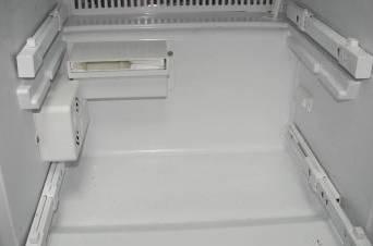
16 4.9 Humidity room 4.11 Water system Water inlet with heater The humidity filter could keep the humidity of food and it is washable Distance part Water filter This part keep the rear side of the appliance from the wall at least 25mm/1, in order to make sure good ventilation 514_ _ARA_EN_H Seite 16 von 76


17 Ice maker Water valve and water tank ~ FD 8905 FD 8905 ~ FD 9005 ¼ ¼ ¼ ¼ ¼ ¼ 5/16 5/16 ¼ ¼ 5/16 5/16 5/16 ¼ ¼ ¼ 5/16 Ice maker test switch 514_ _ARA_EN_H Seite 17 von 76
 (red black red white) 3 Flap")

18 4.12 IWD(ice water dispenser) Connectors water outlet nozzle 2 Ice outlet flap(with heater inside) 3 Ice outlet flap motor 4 IWD housing heater switch Flap heater signal 2 Flap motor signal (yellow yellow white white) (red black red white) 3 Flap position feedback signal (red black blue gray) 4 IWD LED light (red black red black) Be careful about connectors 1 and 2. The male and female plugs could be mismatched. If they are mismatched, the flap will not stop running. 514_ _ARA_EN_H Seite 18 von 76


19 4.13 Switches FC light switch RC light switch main switch IWD housing heater switch In order to avoid dew water at the dispenser, there is heater in the IWD housing. The heater of some VIBs was control by control module, and some VIBs was controlled by heater switch. If there are dew water at the dispenser, please turn the heater on via this switch. 514_ _ARA_EN_H Seite 19 von 76


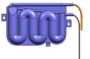
20 Accumulator 5 FUNCTIONS 5.1 Cooling system FC Low press area RC Fin evaporator Solenoid valve Capillary Muffler Compressor FC fin evaporator High press area Condense r FC heating tube Filter TCD Airflow Two evaporators(fc/rc) are sharing one compressor and one solenoid valve controls the cooling circuit when any compartment needs refrigeration. If the appliance equiped with inverter compressor, the refrigerant goes through the condenser first then the FC heating tube. If the appliance equiped with normal compressor, the refrigerant goes through the FC heating tube then the condenser. 514_ _ARA_EN_H Seite 20 von 76
. The temperature range of RC is from 2 to 8 / 35 to 46 (USA).")
21 5.2 Electronic control This appliance is equipped with 5 NTC sensors which control the temperature of FC, RC, TCD, FC-evaporator, RC-evaporator respectively. FC/RC Running and temperature control The temperature range of FC is from-16 to -26 / 7 to -15 (USA). The temperature range of RC is from 2 to 8 / 35 to 46 (USA). When the temperature of FC or RC rises, the control module connects the solenoid valve (opens to FC evaporator or RC evaporator), FC-fan or RC-fan, compressor, the FC or RC is under cooling. Once the slected temperature is reached, it disconnects the fan, and also closes the solenoid valve. OFF: T Tsetpoint + Toffset (2K) + Thysteresis (2.5 K) When both compartments need refrigeration, FC has the priority. The exchanging time between FC and RC will be 30min/20min. During the compartment running progress, when the relevant door is open, compressor is still functioning but the relevant fan stops. TCD temperature control The temperature of TCD can only be set as 0, 2, or 4 / 32, 35.5 or 39 (USA). When the temperature of TCD rises, the control module connects the two flaps, flaps open and TCD fan runs intermittently, the heater attached to the air inlet flap stays off. Once the selected temperature is reached, the fan stays off and the flaps are closed, but heater runs intermittenly. FC Set point Set point RC/ FC RC Set point ON: T Tsetpoint + Toffset (2K) + Thysteresis (2.5 K) TCD on: Fan on/off (4min/2min) Flaps open Flap heater off TCD off: Fan off Flaps closed Flap heater on/off(2min/4min) 514_ _ARA_EN_H Seite 21 von 76
22 5.3 Alarm function 5.4 Compartment fans Door opening alarm When the door is opened over than 1min the buzzer sounds. Temperature alarm The temperature warning signal switches on if the FC/RC/TCD is warmer than -1 / 18 / 35, 34 /64.5 /95 (USA). AL shows on the FC/RC display panel. Touch the alarm/lock button to release the warning signal. The temperature display indicates for 10 seconds the warmest temperature which was reached in the FC/RC/TCD. Then the target temperatures are displayed again on FC, RC and TCD panel respectively. The AL display goes out as soon as the FC/ RC/ TCD set temperature reaches -5 /14 / 14, 23 /57 /57 (USA). Same in the super function. 22 ºC 18 ºC 14 ºC 0 ºC -1ºC -5ºC Refrigerator Freezer 1 When the door is open, the fan is switched off; after the door is open more than 10min, the fan is switched on. 2 After door was closed the fan is switched on for 30s. 3 The fan is switched on when the relevant compartment is in chilling. 4 When the RC is not in chilling, the refrigerator fan is in ON/OFF status (2min ON/ 10min OFF). 5 When the FC is not in chilling, the freezer fan stays OFF. 6 Initial speed of fans are decided by ambient temperature. 7 Input voltage of RC fan increases 1v after the first 30min, and increases another 0.5v after the second 60min. 8 FC fan speed increases 300rpm after the first 120min, and increases another 200rpm after the second 60min. Fan speed is controlled by the ambient temperture measured by ambient sensor on the DoM. 5.5 Condenser fan 1 The fan will switch on 1 minute later after the compressor starts to run when the appliance switch on with a selfdiagnosis program. 2 When the ambient temperature is below 18 /64.5, the fan is in the ON/OFF status(3min ON/ 3min OFF) 3 The fan is always running when the compressor is running. 4 Initial speed of the fan is decided by ambient temperature. 5 Input voltage of RC fan increases 1v after first 30min, another 0.5v after second 60min. Buzzer + Buzzer + Alarm Alarm 514_ _ARA_EN_H Seite 22 von 76
23 5.6 Defrosting mode FC Factors affect the start of defrosting: Last defrosting period Appliance running time Compressor running time Door openings times FC defrost phase will be triggered at the earliest after 6 hours and at the latest after 73 hours of operating time. PHASE I: All components switch off for 5 minutes. PHASE II: Defrosting heater switches on until the evaporator reaches 6 ºC/43 or for a maximum of 45 minutes. PHASE III: Drain heater runs for another 6 minutes. Afterwards, the appliance switches to the normal operation. 6 ºC Or 43 5 min 6 min 5.7 Defrosting mode RC Factors affect the start of defrosting: Last defrosting period Appliance running time Compressor running time Door openings RC defrost phase will be triggered at the earliest after 8 hours and at the latest after 73 hours of operating time. PHASE I: RC fan switches on for 10 minutes. PHASE II: All components switch off for 2 minutes. PHASE III: Defrosting heater switches on until the evaporator reaches 8 ºC/46.5 or for a maximum of 30 minutes. PHASE IV: All components switch off for 3 minutes. Afterwards, the appliance switches to normal operation. During the RC defrosting cycle, the compressor may run because of chilling in FC. 10 min 8 ºC Or min 3 min 45 min 30 min Drain heater 514_ _ARA_EN_H Seite 23 von 76
24 5.8 Ice water system Water circuit ice maker Ice Maker water inlet system tube tube Rear of freezer tu b e Water tube Water filter tube Distributed tu b e Water export tube Below hinge of freezing tube Water tank There are two kinds of replacement filters. Screen filter: (with PP filtration inside), Mat-Nr Ultraclarity filter :(with carbon block inside) Mat-Nr _ _ARA_EN_H Seite 24 von 76
25 5.9 Start up program The start up program is activated if all the temperature sensors measure temperatures over than 4 /39 while switching on the appliance. Each load of the appliance is switched on for 5 seconds. Sequence is like following: IWD-power Nozzle heater Crush-solenoid Crush-motor IWD-LED Flap motor Valve TCD inlet Flap TCD outlet Flap RC-LED FC-LED TCD-Fan RC-fan FC-fan Condenser-fan FC-Drain Flap-Heater IWD-frame-Heater RC-Defrost FC-Defrost Compressor FC Running 35min RC Running 15min 5.10 Demonstration program The demonstration mode can only be activated within 10 minutes after switching on the appliance. Activation: Switch the appliance off and on again. Press the + and super/quick ice simultaneously for 5 seconds until the display shows 88. Quit: Switch off the appliance to quit. During the demonstration program, all loads are not functioning except lights and door alarm. 514_ _ARA_EN_H Seite 25 von 76
26 5.11 Service program The service program can only be activated within 10 minutes after switching on the appliance. Activation: Switch the appliance off and on again. Press the select and super simultaneously for 5 seconds until the display shows A1 Quit: Switch off the appliance to quit the service program, or it ends automatically if no button is touched for 20min. Navigation inside main menu: Go forwards to next function: press select Go backwards to previous function: press super/quick ice Activate the function: press + Navigation inside each function: Go forwards to next component: press super/quick ice Activate the component: press select Back to main menu: press Options Service program main menu Display Function A1 Button test A2 Display test A3 Components test A4 IWD test A5 Sensor test A6 digital switch A7 Compartment test 514_ _ARA_EN_H Seite 26 von 76
 During this program, the display background light and LCD segments are tested. The program runs automatically. Press options for a long while to quit.")
27 Button test (A1) When the buttons are pressed, the number of the button is showed. Press options for a long while to quit. Display test (A2) During this program, the display background light and LCD segments are tested. The program runs automatically. Press options for a long while to quit. Components test (A3) During this test, the components controlled by control module can be activated. Press super/quick : go to next compoent Press select : switch on the component Display component power consumption Off On c00 c01 compressor ~100W c10 c11 FC deforst heater ~210W c20 c21 RC defrost heater ~ 115 W c30 c31 IWD frame heater ~ 20 W (If it s a model with Door in Door, the door in door heater is forced run here.usa version needs to switch on the heaters see Page16) c40 c41 DiD Heater ~ 10 W (If there is no DID, this is open) c50 c51 TCD flap heater ~ 8 W c60 c61 FC drain heater ~ 45 W c70 c71 condenser fan ~ 8 W c80 c81 FC fan ~ 8 W c90 c91 RC fan ~ 8 W ca0 ca1 TCD fan ~ 8 W cb0 cb1 TCD outlet flap ~ 8 W cc0 cc0 TCD inlet flap ~ 8 W cd0 cd1 solenoid valve ~ 6 W ce0 ce1 IWD power ~ 6 W Press options to quit. 514_ _ARA_EN_H Seite 27 von 76

28 IWD test(a4) During this test, the components controlled by IWD control module can be activated. Press super/quick : go to next compoent Press select : switch on the component Display component power consumption Off On I00 I01 nozzle heater ~ 7 W I10 I11 crusher solenoid ~ 60 W I20 I21 water dispenser valve ~ 7 W I30 I31 crusher motor ~ 110 W I40 I41 Ice maker ~ 7 W I50 I51 dispenser light ~ 7 W I60 I61 dispenser flap motor ~ 7 W Sensor test (A5) Press super/quick : go to next sensor 0 RC sensor 1 RC evaporator sensor 2 FC sensor 3 FC evaporator sensor 4 Not used 5 TCD sensor Digital switch(a6) Off On RC door FC Door Press options to quit. 514_ _ARA_EN_H Seite 28 von 76
29 Compartment test (A7) Each compartment can be individually requested for cooling. Only one compartment can run at any one time. Display Off On Compartment C00 C01 Freezer C10 C11 Cooler C20 C21 TCD 514_ _ARA_EN_H Seite 29 von 76
30 B B B service program Button test A1 A C Display test A2 A C component tests A3 Within the first 10min after switching on the appliance, press select and super B Quit D Enter B Quit D Enter B Quit D Enter C Button test show :b Display test Compressor OFF c00 A Compressor ON c01 show the button number when touching Button test"n" show:bn_ Slect A options B super C + D FC : freezer compartment RC : refrigerator compartment TCD: temperature control drawer evp : evaporator if no DiD, this is open FC Heater RC Heater IWD Heater DiD Heater TCD Flap Heater FCdrainheater C OFF c10 C OFF c20 C OFF c30 C OFFc40 C OFF c50 C OFFc60 C A A A A A A A FC Heater ON c11 RC Heater ON c21 IWD Heater ON c31 DiD Heater ON c41 TCD Flap Heater ON c51 FCdrainheate r ON c61 Condenser Fan OFFc70 Condenser Fan ON c71 C A C IWD Power OFF ce0 A C Solenoid valve OFF cd0 A C TCD Flap 1 OFF cc0 A C TCD Flap 2 OFF cb0 A C TCD Fan OFF ca0 A C RC Fan OFF c90 A C FC Fan OFF c80 A IWD Power ON ce1 Solenoid valve ON cd1 TCD Flap 2 ON cc1 TCD Flap ON cb1 TCD Fan ON ca1 RC Fan ON c91 FC Fan ON c80 C B IWD parts test A4 A C B Quit D Enter Inlet heater OFF I00 C Crush solenoid OFF I10 C Water valve OFF I20 C Crush motor OFF I30 C Ice maker OFF I40 A A A A A Inlet heater Crush solenoid Water valve Crush motor Ice maker ON ON I01 ON I11 ON I21 ON I31 I41 C C LED OFF I50 A LED ON I51 Flap motor OFF I60 A Flap motor ON I61 B B B sensor test A5 A C switch A6 A C compartment test A7 B Quit D Enter B Quit D Enter B Quit D Enter 0 RC Sensor C 1 RC C C 3 FC C 4 No C 2 FC Sensor Evp. sensor Evp.sensor definition C C C 00 no use 10 no use 20 no use 30 RC door C 40 FC door C C TCD OFF FC OFF c00 RC OFF c10 c20 A A A C C 5 TCD Sensor FC ON c01 RC ON c11 TCD ON c21 quit 514_ _ARA_EN_H Seite 30 von 76
31 5.12 Self-diagnosis program The self-diagnosis program can only be activated within 10 minutes after switching on the appliance. L12 IWD-Heater L13 RC-Defrost L14 FC-Defrost L15 Compressor Press select and options simultaneously for 5 sec until the left display shows L0. The self-daignosis program runs as follows, L0 IWD-power L1-Valve L2- TCD inlet Flap L3 TCD outlet Flap L4 RC-LED L5 FC-LED L6 TCD-Fan L7 RC-fan L8 FC-fan L9 Condenser-fan L10 FC-Drain L11 Flap-Heater

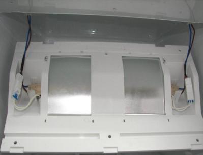
32 5.13 Ice maker 514_ _ARA_EN_H Seite 32 von 76
33 Working principle This ice maker is purely mechanical controlled. Following picture is the original position of every compoents in the ice maker. 514_ _ARA_EN_H Seite 33 von 76
34 Step 1 Press the Rocker switch, Pin 2 and Pin 2a are connected. The ice maker is switched on. No part is working untill the thermostat reachs - 9. Step 2 Therostat connected the whole power circuit, motor is running and heater is switching on. 1 st loop starts. Step 3 During the 1 st loop running, the ice level switch will be released once, but no effect on the power circuit. Motor is running and heater is on. Step 4 When the notch of the ice cam run to the water valve switch, which means the ice cam switch is released, the water valve is switched on. Water comes into the ice maker. End of the 1 st loop. Step 5 Ice making progress. Every component of ice maker is at the same position as step 1, as soon as the thermostat reaschs -9, which means ice is ready, It can go forward. Step 6 Beginning of 2 nd loop. Motor is running, heater is switched on. When stripper runs into the ice position to take the ice out. Step 7 Due to the thermostat is not over than 9, when the notch of ice cam runs to the water valve switch by the end of 2 nd loop, the water vavle is not connected. Step 8 Beginning of 3 rd loop, motor is running, and heater is on, keeping heating the thermostat to reach 9. Step 9 When thermostat is over than 9, the thermostat disconnected, but motor is keeping running till the notch of ice cam reaches the water valve switch. Step 10 Same as step 4. The new ice production cycle like following steps over and over again, untill the ice level switch detect that ice box if full of ice cubes. 514_ _ARA_EN_H Seite 34 von 76
35 When the ice box is full. All components stay at the original position. No more working. Self Diagnose mode Switch off the freezer light and push the rocker switch to unstable position for more than 15seconds. When the rocker switch is pressed position 1 will connect to 1a and position 2 will connect to position 2a. The Motor will drive the IM CAM turn CCW at about 0.33 RPM, the heater is switch on the same time. From original status the rocker switch should be pressed totally about 15 seconds. Then release the rocker switch, IM will go on to finished the self test. Conditions for switching on the water valve to Ice maker It must fulfill both following conditions, the valve can swith on and the water can enter the ice maker. Thermostat is open circuit Water valve microswitch is released Datas of ice maker Ice production rate in normal condition EU/CN models 1700g/24h US models 2000g/24h Ice production rate in quick ice mode 2500g/ 24h for all models Rotate speed of rotor 0.33rpm Water filling time 4.8~5.3s Open circuit temperature of Thermal fuse around 70 /158 Close circuit temperature of Thermostat -9 /16 Open circuit temperature of Thermostat 9 /48 514_ _ARA_EN_H Seite 35 von 76


36 6 REPAIR 6.1 Light switch and main switch 6.2 PCBs IWD PCB CM, main PCB 514_ _ARA_EN_H Seite 36 von 76


37 Display module 6.3 Ice maker Step1 take out 4 screws, Torx-20 Under the dispenser flap support, there are two notches for service to take out the display module. Step2 remove the cover of light Step3 take out 4 screws, Torx _ _ARA_EN_H Seite 37 von 76


38 6.4 Water filter head 1 disassemble the screw and water tube Step4 unplug the ice maker Before After 2 disassemble the water fillter Step5 lift the ice maker a little then take out the it completely. 3 Disassemble the screw on the water filter head and pull it out. 514_ _ARA_EN_H Seite 38 von 76


39 6.5 Water tank 6.6 Water tube and IM inlet nozzle 1 disassemble the water tube from the water valve 1 Disassemble the tube from the water valve Before After Before After 2 Disassemble the quick connector under the appliance 2 Open the cover behind appliance 3 Disassemble the screw and pull the water tank out 3 Disassemble the tube from the IM inlet nozzle and pull it out. 514_ _ARA_EN_H Seite 39 von 76


40 4, Disassemble the IWD 7, Disassemble the quick connector behind the DOM and pull the water tube out. 5 Disassemble the connection and take the IM inlet nozzle out. 6 Disassemble the quick connector under the appliance 514_ _ARA_EN_H Seite 40 von 76


41 6.7 Access to freezer evaporator Remove 2 screw covers Take out 1 screw(torx 20) from the lower airflow cover Take down the lower airflow cover, be careful of the two hooks 514_ _ARA_EN_H Seite 41 von 76


42 Take out 1 screw (Torx 20) from the evaporator cover Release 2 hooks from the fan housing, then take down the evaporator cover. Be careful of the rest 10 hooks, there are marks at the front side of the evaporator cover. Lift up the upper airflow cover 514_ _ARA_EN_H Seite 42 von 76


43 6.8 Access to refrigerator evaporator Disassemble the excenter shelf take down 2 holders, then remove the glass shelf, metal bar last. E F Unconnect the water tube from the water vavle in the compressor room first! G H Light and filter system A B Airflow cover C D 514_ _ARA_EN_H Seite 43 von 76

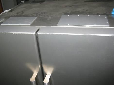
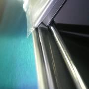
44 Take out water tank and the evaporator cover Behind the two screw covers there are two Torx20 screws! 514_ _ARA_EN_H Seite 44 von 76


 密封件 (618579) 电子件")


45 6.9 TCD Flap This sponge has been added on the inlet flap from FD8904 Sponge sealing 1 2 In FC side, 4 Trox-10 screws In RC side, 3 Trox-10 screws To make sure the TCD flap is well sealed, please use repair sealing kit. Mat-Nr: TCD-Flap(615548) 密封件 (618579) 电子件 (650628) A D Take out the flap from FC Unplug the TCD fan and A sponge sealing side could be used if there is noise Flap from this inlet flap caused by the icing when the flap motor runs. Mat.Nr: A B C E F 514_ _ARA_EN_H Seite 45 von 76


46 insert the styrofoam part B & C stick the part D like following C B Freezer side D Freezer side Fasten the wirings with part F stick the part E & A like following F E A Cooler side Cooler side 514_ _ARA_EN_H Seite 46 von 76


47 6.10 Compressor Room Compressor room cover Torx-20 screw Philips screw Inverter box Unplug the wiring connectors and cut the fasten belt 1screw, Philips 514_ _ARA_EN_H Seite 47 von 76


.")
48 Compressor Water valves For EU models, the water valve part is like following. Use a small 10mm wrench to move the 4th screw. FD 8905, there are 4 screws fixing the compressor. power module water valve to icemaker water valve to water dispenser For US models, the two valves are integrated, one inlet(screw-nut connection), two outlets(quick connection). From FD 9105 all appliance use the US model valve 514_ _ARA_EN_H Seite 48 von 76

 Cut the old receptacles from the wirings.")
49 Change EU models to US models, because the EU models wasn t provided, so you should order to substitute it. The repair kit contains the following items for you to change the valves and connect all different versions of water system used in X-Cool SbS. 1. Change the wirings receptacles of valve system Old production: Shrinking tube ¼--¼ 250 Connector Quick connector ¼--5/16 5/16--5/ Connector 1/4 water tube Combination valve 5/16 water tube Fasten belt 5/16 tube bending part 1/4 tube bending part 1) Cut the old receptacles from the wirings. 2) Use the receptacles provided in the service kit to connect the wirings in the following way. 514_ _ARA_EN_H Seite 49 von 76
50 Yellow wire-- Power for Ice maker inlet valve Blue wire-- Neuter wire Red wire-- Power for Dispenser inlet valve 3) use the shrinking tube to wrap round the receptacles 4) Since the valves are using AC power, the live and neuter wirings can be switched. 2. Change the water path system You will find the water path in the appliance in front of you is one of the following types. 1) Please following the following steps to use the parts served with the service kit. 2) insert the filter outlet tube into the new valve inlet. 3) take out the old tube between the valve and the ice maker inlet, which is inside the case. Use the new water tube (1/4 ) instead, cutting to the adequate length if necessary. Diameter of the tank inlet tube Diameter = 1/4 Diameter = 5/16 Length of the tank inlet tube Enough Not Enough Enough Not Enough Solutions Insert the 5/16 tube into the valve, then connect the tube to the tank inlet tube with a 1/4-5/16 quick connector. Insert the tank inlet tube into the valve directly. Insert the 5/16 tube into the valve, then connect the tube to the tank inlet tube with a 5/16-5/16 quick connector. 4) Observe the inlet tube of water tank, both length side and diameter side, then find the solution in the table. 5) Use two tube banding parts to protect the two different tubes. 6) Use fasten belt to fix the wirings and water tubes. 514_ _ARA_EN_H Seite 50 von 76


51 Power module After remove the water valves, you will see Pull out the power module 1 1 Remove two screws 514_ _ARA_EN_H Seite 51 von 76
52
 Check the \"control signal\" connector in inverter box 514_58300000138441_ARA_EN_H -22.09.")
53 Check point Check the AC power input on the inverter driver Check the control signal In detail Power cord connection Recheck the connection between Inverter and compressor Check frequency the X4.5 and X4.7 (Working: Hz Rest:16Hz) Check the "control signal" connector in inverter box 514_ _ARA_EN_H Seite 53 von 76


54 6.11 Leakage at the water dispenser 1 Take out the display module, see chapter Tidy the tube of base panel to get enough length. Adjust the tube from purple position to green poistion. 2 Disassemble the water adapter Press down the retaining ring, hold it tight and pull the tube out Please do make sure the length left out of the door is more than 70mm! 70mm 3 Cut the water tube in the right way, and make sure the length will be cut approximately 12 mm. Cut Off Line 12mm Lay down the tube on a rigit board and cut. Make sure the cut-surface is in a 90 angle and smooth. 5 Insert the tube into a NEW nozzle make sure the tube insert length is approximately 18mm. 514_ _ARA_EN_H Seite 54 von 76

 Adjust the feet")


55 6.12 Adjust the door State: the freezer door is 6mm higher than the cooler door Method 1, 1) Adjust the feet until the door become the equal. 2) Adjust the feed in the back of the appliance until the appliance became the same level 514_ _ARA_EN_H Seite 55 von 76


56 Method 2: About the not horizontal doors, a special washer could be inserted between the lower door hinge and the door closer to make the two doors even. Result: The door became the same level Washer Mat.Nr: Thickness:0.5mm Material: plastic 514_ _ARA_EN_H Seite 56 von 76
")

.")


57 6.13 DiD (door in door) option* DiD light switch. Two philips screws(old). Disassemble the DiD. DID light swithch (new made after ) Take out the two covers Move two springs towards center Door in door can be moved easily 514_ _ARA_EN_H Seite 57 von 76

58 6.14 RF not working* State: RF not working and lamp is running Reason: the fuse is failure Method: replace power supply module by new one. New material code is Remark: write yellow marked on the back of RF By the way, change KI to 90 on the nameplate and then activating the water-valve by self programme 514_ _ARA_EN_H Seite 58 von 76
59 7 FAULT DIAGNOSTICS 7.1 Error code explanation E01 E02 E03 E15 E10 E11 E20 E21 RC sensor value is outside the defined range FC sensor value is outside the defined range TCD senor value is outside the defined range Ambient sensor value is outside the defined range CM Eeprom DOM Eeprom Communication error between CM and DOM Communication error between DOM and IWD 7.2 Appliance does not start Consequence Cause/ Measures Remedial action Compartment lamp is lighting but the DoM is dark Power supply -No power supply -Power supply 187V Main switch doesn t work Check the power cord Check the inverter PCB of compressor Check the temperature sensors Power module is dead If the power supply is in the range of 187~242V(USA 115V), replace the power module Replace the main switch Replace the power cord Reconnect or change if necessary Change the sensor if necessary Change the power module 514_ _ARA_EN_H Seite 59 von 76
60 7.3 RC/FC not cold enough Consequence Cause/ Measures Remedial action check the fans check the power supply to the fan change the Control module No air circulation in FC/ RC mechanically failure change the fan when the relevant compartment is running incorrect or no connection re-connect light switch failure change the switch Compartment sensors failure replace the sensor fan noise 7.4 TCD not cold enough check position if the fan blade touching the housing re-install the fan Inadequate cooling capacity Check cooling circuit for leaks Reapair the cooling system Consequence Cause/ Measures Remedial action check the fans and flaps check the power supply to the fan change the Control module No air circulation in TCD when mechanically failure change the fan or flaps TCD is in cooling incorrect or no connection re-connect Compartment sensors failure replace the sensor Condensation around inlet flap Check the heater of flap Replace the flap 514_ _ARA_EN_H Seite 60 von 76
61 7.5 Snow and ice in FC Consequence Cause/ Measures Remedial action Snow and ice in the Check the freezer door gasket Change the door gasket compartment Check the ice chute flap Replace the flap Snow and ice on the food Change the evapaorator Check the deforst heater and sensor or control module if evaporator sensor necessary Temporary snow on the food High humidity food Advise customer 7.6 Dew water Consequence Cause/ Measures Remedial action Dew water in RC Check the refrigerator door gasket Change the door gasket Dew water at side panels Check local humidity Advise customer Dew water at right side of freezer door Dew water at IWD housing Check the heater inside the door Check the heaters behind the IWD houseing Change the door if required Switch on the manually heater if necessary change the freezer door 514_ _ARA_EN_H Seite 61 von 76
62 7.7 Noise Consequence Cause/ Measures Remedial action Fan blade touching the housing Re-attach the fan fan noise Fan vibration Fasten the screws Compressor noise Noise from IWD Noise when open or close door Cooling tube noise Regular noise from compressor room when compressor runs at a high speed, the sound will alse be higher See touble shooting IWD Frictional sound between the door closer and base hinge Drain outlet valve blocked Check the cooling tubes if touches each other in compressor compartment or evaporator area. Valve(to ice maker)noise, which occurs when there is no water connection and the ice maker is ON. Due to insufficient voltage from ice maker to the vavle. It is normal. Advise customer Change base hinge or door closer. Change the Drain outlet Adjust the cooling tube to avoid the tube touches each other Advice customer, maker sure the ice maker is switched off when there is no water connection. 514_ _ARA_EN_H Seite 62 von 76

63 7.8 DOM operation 7.9 IWD trouble shooting tree No ice production Anything is wrong Dispensing problem 514_ _ARA_EN_H Seite 63 von 76
64
65 514_ _ARA_EN_H Seite 65 von 76
66 514_ _ARA_EN_H Seite 66 von 76
67
68 514_ _ARA_EN_H Seite 68 von 76
69 7.10 Display Light Noise and No power trouble shooting tree Display functionality Light Anything is wrong Noise No power
70 514_ _ARA_EN_H Seite 70 von 76
71 514_ _ARA_EN_H Seite 71 von 76
72 Remark: E00 Sensor value for 4th compartment is outside the defined range (does not affect E2006 touch) E01 Sensor value for refrigerator compartment is outside the defined range E02 Sensor value for freezer compartment or soft freezer compartment is outside the defined range E03 Sensor value for chiller compartment, wine storage compartment or chiller compartment is outside the defined range E05 Sensor value for vaporiser of 4th compartment is outside the defined range (does not affect E2006 touch) E06 Sensor value for refrigerator compartment vaporiser is outside the defined range E07 Sensor value for freezer compartment compressor or soft freezer vaporiser is outside the defined range E08 Sensor value for chiller compartment vaporiser, wine storage compartment vaporiser or chiller compartment vaporiser is outside the defined range E10 EEPROM/data flash in control module not compatible with software or memory damaged in control module E11 EEPROM/data flash in display module not compatible with software or memory damaged in display module E15 Sensor value for ambient sensor is outside the defined range E20 Communication error between CM and DOM E21 Communication error between IWD and DOM E30 Timeout of CM E31 Timeout of IWD 514_ _ARA_EN_H Seite 72 von 76
73 8 TECHNICAL SPECIFICATIONS 8.1 Datas of components Freezer fan motor DC 12V input power 4W +10% / -20% Cooler fan motor DC 12V input power 2.8W +10% Condenser motor DC 12V input power 3.7W+10%/- 20% TCD fan motor DC 12V input power 0.8W ± 15% Light bulb solenoid valve crusher solenoid water dispenser valve crusher motor Ice maker dispenser light dispenser flap motor ~ 40 W ~ 6 W ~ 60 W ~ 7 W ~ 110 W ~ 7 W ~ 7 W ~ 7 W EU models Solenoid valve to water dispenser: White, 4060 Ohm, flow rate (at 1-8 bar) ±10% is 2.0 l/min, Solenoid valve to ice maker: Green, 4060 Ohm, flow rate (at 1-8 bar) ±10% is 1.0 l/min FC deforst heater 240V 50Hz 230W+5% RC defrost heater 230V 50Hz 120W+5% IWD frame main heater+ door sheet heater 230V 50Hz 14.3W+5% IWD assistant heater 230V 50Hz 2.2W+5% TCD flap 230V 50Hz ~8W FC drain heater 240V 50Hz 40W±5% nozzle heater 230V 50Hz 1.5W+5% US models Water valve 110V 60Hz flow rate (at 1-8 bar) ±14% is 1.1 l/min, FC deforst heater 120V 60Hz 230W+5% RC defrost heater 110V 50Hz 120W+5% IWD frame main heater+ door sheet heater 120V 60Hz TCD flap 120V 60Hz ~8W 12.5W+5% FC drain heater 120V 60Hz 40W±5% nozzle heater 120V 60Hz 1.5W+5% 514_ _ARA_EN_F Seite 73 von 76

74 8.2 NTC Sensor 514_ _ARA_EN_F Seite 74 von 76
75 EAN (kwh/d) RED (%) RC tempture FC tempture 8.3 Temperature curve Cooling test EU- characteristic curve fridge % % 80% 70% EAN: Mean energy absorption per day RED: Relative compressor ON duration 60% 50% 40% 30% 20% % Set point (2C,2C,-24C) Set point (5C,2C,-20C) TCD setting 2C Set point (8C,2C,-15C) _ _ARA_EN_F Seite 75 von
76 EAN (kwh/d) RED (%) RC tempture FC tempture Cooling test US- characteristic curve fridge % % 80% 70% EAN: Mean energy absorption per day RED: Relative compressor ON duration 60% 50% 40% 30% Set point (2C,2C,-24C) 20% % Set point (5C,2C,-20C) TCD setting 2C Set point (8C,2C,-15C) _ _ARA_EN_F Seite 76 von 76
1 SAFETY REPAIR COMPONENTS FUNCTIONS FAULT DIAGNOSIS X-Cool Side by Side Refrigerator
 1 SAFETY... 3 1.1 Safety instructions... 3 1.2 Repair instructions... 3 2 COMPONENTS... 4 2.1 Overall view... 4 2.2 Compressor room... 4 2.3 Power Control Boards (PCB)... 5 2.4 Temperature sensor... 6
2 INSTALLATION OPERATION FUNCTIONS SAFETY Compressor Compartment... 10
 REPAIR INSTTRUCTTI I ION REFFRI IGERATTOR 1 SAFETY... 3 4.1 Compressor Compartment... 10 2 INSTALLATION... 4 4.2 Fridge Evaporator Compartment... 11 4.3 Freezer Evaporator Compartment... 12 3 OPERATION...
Refrigerator KE T
 Refrigerator KE 680-1-3T Service Manual: H8-74-07 Responsible: U. Laarmann KÜPPERSBUSCH HAUSGERÄTE AG E-mail: uwe.laarmann@kueppersbusch.de Tel.: (0209) 401-732 Customer Service Fax: (0209) 401-743 Postfach
Side-by-side combined refrigerator-freezer
 REPAIR INSTTRUCTTI I IONS Side-by-side combined refrigerator-freezer 1 SAFETY... 2 4.1 Electronic controller... 8 1.1 Safety instructions... 2 1.2 Repair instructions... 2 2 INSTALLATION... 3 3 OPERATION...
1 SAFETY INSTALLATION OPERATION REPAIR COMPONENTS FUNCTIONS... 12
 1 SAFETY... 3 1.1 Safety instructions... 3 1.2 Repair instructions... 3 2 INSTALLATION... 4 3 OPERATION... 5 3.1 Freezer Set button... 5 3.2 Refrigerator Set button... 5 3.3 Super Cool button... 5 3.4
Refrigerator IKE IKE IKE 229-6
 Refrigerator IKE 159-6 IKE 189-6 IKE 229-6 Service Manual: H8-71-06 Responsible: Uwe Laarmann KÜPPERSBUSCH HAUSGERÄTE AG E-mail: uwe.laarmann@kueppersbusch.de Phone: (0209) 401-732 Kundendienst Fax: (0209)
SERVICE INSTRUCTION. DYNAMIC COOLING with 0 zone REFRIGERATION. Fridge/freezer with. Publication number
 SERVICE INSTRUCTION REFRIGERATION DISTRIPARTS AB BOX 501 S-562 80 NORRAHAMMAR Phone 036-31 80 00 Telefax 036-31 81 10 Telefax 036-31 80 88 Publication number 599 51 96-71 Rev. 04-04-20 SV/SERVICE DT/MA/AN
SERVICE MANUAL REFRIGERATION
 SERVICE MANUAL REFRIGERATION Electrolux Home Products S.p.A. Spares Operations Italy Corso lino Zanussi, 30 I - 33080 Porcia (PN) Fax +39 0434 394096 S.O.I. Edition: 10.2006 Publication no. 599 38 38-50
Service Information. WNes 2956 appliance documentation. Service Information no. 27/2004 LHG/TKD-Fe/June SI
 After Sales Service International Service Information Service Information no. 27/2004 LHG/TKD-Fe/June 2004 WNes 2956 appliance documentation Page 1/26 Contents 2.0. Extract from Operating Instructions
SERVICE MANUAL REFRIGERATION
 SERVICE MANUAL REFRIGERATION ELECTROLUX HOME PRODUCTS S.p.A. Publication no. Spares Operations Italy 599 37 75-07 Corso Lino Zanussi, 30 060824 I - 33080 PORCIA / PN (ITALY) ITZ/SERVICE/AA Fax +39 0434
4. ALIGNMENT AND ADJUSTMENTS
 4-1) Forced Operation Function (Pull-down / Refrigerator Defrost / Refrigerator. Freezer-Defrost / Cancellation) 28 4-2) Sound function 29 4-3) Exhibition Function 29 4-4) Self-Diagnostics Function29 4-5)
FOR SERVICE TECHNICIAN S USE ONLY
 FOR SERVICE TECHNICIAN S USE ONLY NOTE: This sheet contains important Technical Service Data. Tech Sheet Do Not Remove Or Destroy DANGER Electrical Shock Hazard Only authorized technicians should perform
4. Alignment and Adjustments
 . Alignment and Adjustments -) Forced Operation Function (Pull-down / Refrigerator Defrost / Refrigerator. Freezer-Defrost / Cancellation) 3 -) Self-Diagnostics Function 3-3) Load Operation Check Function
TABLE OF CONTENTS REFRIGERATOR-FREEZER. Model No. NR-BN34FX1 Model No. NR-BN34FW1
 Order Number GORR1405001CE REFRIGERATOR-FREEZER Model No. NR-BN34FX1 Model No. NR-BN34FW1 Product-Color X:Stainless W:White Destination E(Europe Continental) B(U.K.) TABLE OF CONTENTS PAGE 1 Safety Precautions-----------------------------------------------
CABINET PARTS For Models: ED5LHEXTD00 (Universal Silver)
") CABINET PARTS REFRIGERATOR 06 07 Litho In U.S.A. (mat) 1 Part No. Rev. A CABINET PARTS 1 Literature Parts 2309541 Use & Care Guide 2311815 Service & Wiring Sheet 2325842 Energy Label 2261037 Instruction
CABINET PARTS REFRIGERATOR 06 07 Litho In U.S.A. (mat) 1 Part No. Rev. A CABINET PARTS 1 Literature Parts 2309541 Use & Care Guide 2311815 Service & Wiring Sheet 2325842 Energy Label 2261037 Instruction
SERVICE MANUAL REFRIGERATION
 SERVICE MANUAL REFRIGERATION ELECTROLUX ZANUSSI S.p.A. Publication No. Spares Operations Italy 599 35 40-29 Corso Lino Zanussi, 30 020806 I - 33080 PORCIA / PN (ITALY) ITZ/SERVICE/AA EUROFLEC With exposed
Fast Track Troubleshooting
 Fast Track Troubleshooting Model: RH22** Bulletins: IMPORTANT SAFETY NOTICE For Technicians Only This service data sheet is intended for use by persons having electrical, electronic, and mechanical experience
CABINET PARTS For Model: JS42CXFXDB00 (Etched Aluminum)
") CABINET PARTS 42" BUILT IN REFRIGERATOR 1 08 Litho In U.S.A. (mat) 1 Part No. Rev. A CABINET PARTS 1 Literature Parts W10151251 Use & Care Guide W10164079 Energy Guide W10159831 Service & Wiring Sheet
CABINET PARTS 42" BUILT IN REFRIGERATOR 1 08 Litho In U.S.A. (mat) 1 Part No. Rev. A CABINET PARTS 1 Literature Parts W10151251 Use & Care Guide W10164079 Energy Guide W10159831 Service & Wiring Sheet
Essentia Project Artica Platform No Frost 60 cm Appliances 2011
 Essentia Project Artica Platform No Frost 60 cm Appliances 2011 Event Ca Maiano, May 2011 Presenter Piotr Kelm Francesco Nieli 0 Legend and User Interface Legend THR3 Interface (SQG_CL_32) MID Indesit
KitchenAid Food Stream Solutions Classic and Integrated Series
 KitchenAid Food Stream Solutions Classic and Integrated Series KitchenAid Chapter list Installation Range overview Installation General Information Function Compressor Power Control Board Defrosting Heating
CABINET PARTS For Model: KBLC36FTS06 (Stainless Steel)
") CABINET PARTS 36" BOTTOM MOUNT BUILT IN REFRIGERATOR 4 12 Litho In U.S.A. (mlg)(bay) 1 Part No. Rev. A CABINET PARTS 1 Literature Parts W10303987 Use & Care Guide W10205624 Energy Guide W10483322 Service
CABINET PARTS 36" BOTTOM MOUNT BUILT IN REFRIGERATOR 4 12 Litho In U.S.A. (mlg)(bay) 1 Part No. Rev. A CABINET PARTS 1 Literature Parts W10303987 Use & Care Guide W10205624 Energy Guide W10483322 Service
WHIRLPOOL REFRIGERADOR GS2SHGXLQ01
 CABINET, LITERATURE 1 CABINET, LITERATURE 1 LIT2220425 LITERATURE PARTS (Energy Label) 1 LIT2220699 LITERATURE PARTS (Owner`s Manual) 1 LIT2255381 LITERATURE PARTS (Service & Wiring Sheet) 1 LIT628370
Fast Track Troubleshooting
 Fast Track Troubleshooting Models Covered: RF266AD**/XAA French Door Refrigeration IMPORTANT SAFETY NOTICE For Technicians Only This service data sheet is intended for use by persons having electrical,
SERVICE MANUAL WASHING MACHINE MODEL : WD-10120FD WD-12120(5)FD WD-14120(5)FD FWD-12120(5)FD FWD-14120(5)FD CAUTION
FD WD-14120(5)FD FWD-12120(5)FD FWD-14120(5)FD CAUTION") website : http://www.lgeservice.com e-mail : http://lgeservice.com/techsup.html WASHING MACHINE SERVICE MANUAL CAUTION READ THIS MANUAL CAREFULLY TO DIAGSE TROUBLE CORRECTLY BEFORE OFFERING SERVICE. MODEL
website : http://www.lgeservice.com e-mail : http://lgeservice.com/techsup.html WASHING MACHINE SERVICE MANUAL CAUTION READ THIS MANUAL CAREFULLY TO DIAGSE TROUBLE CORRECTLY BEFORE OFFERING SERVICE. MODEL
FOR SERVICE TECHNICIAN S USE ONLY
 F SERVICE TECHICIA S USE OY TE: This sheet contains important Technical Service Data. Tech Sheet Do ot Remove Or Destroy DAGER Electrical Shock Hazard Only authorized technicians should perform diagnostic
JBL2088HES JBL2088HES0, JBR2088HES JBR2088HES0, JFC2089HEP JFC2089HEP0, JFC2089HES JFC2089HES0, JFC2089HPF JFC2089HPF0, JFC2089HPY JFC2089HPY0
 Bottom Mount Refrigerator Technical Information JBL2088HES JBL2088HES0, JBR2088HES JBR2088HES0, JFC2089HEP JFC2089HEP0, JFC2089HES JFC2089HES0, JFC2089HPF JFC2089HPF0, JFC2089HPY JFC2089HPY0 Due to a possibility
SERVICE MANUAL WASHING MACHINE FWD-12120(5)FD FWD-14120(5)FD FWD-16120(5)FD DWD-12120(5)FD DWD-14120(5)FD DWD-16120(5)FD
FD FWD-14120(5)FD FWD-16120(5)FD DWD-12120(5)FD DWD-14120(5)FD DWD-16120(5)FD") website : http://www.lgeservice.com e-mail : http://lgeservice.com/techsup.html WASHING MACHINE SERVICE MANUAL CAUTION READ THIS MANUAL CAREFULLY TO DIAGSE TROUBLE CORRECTLY BEFORE OFFERING SERVICE. MODEL
website : http://www.lgeservice.com e-mail : http://lgeservice.com/techsup.html WASHING MACHINE SERVICE MANUAL CAUTION READ THIS MANUAL CAREFULLY TO DIAGSE TROUBLE CORRECTLY BEFORE OFFERING SERVICE. MODEL
CABINET PARTS For Models: ASD2522WRS07 (Stainless)
") CABINET PARTS REFRIGERATOR 9 11 Litho In U.S.A. (wam) (psw) 1 Part No. Rev. A CABINET PARTS 1 Literature Parts W10321484 Use & Care Guide W10275776 Service & Wiring Sheet W10234042 Energy Guide 628370
CABINET PARTS REFRIGERATOR 9 11 Litho In U.S.A. (wam) (psw) 1 Part No. Rev. A CABINET PARTS 1 Literature Parts W10321484 Use & Care Guide W10275776 Service & Wiring Sheet W10234042 Energy Guide 628370
NO. F ISSUED: JUN. 15, 2009 REVISED: HOSHIZAKI MODULAR CRESCENT CUBER KMD-201AA KMD-201AWA MODEL SERVICE MANUAL
 NO. F037-775 ISSUED: JUN. 15, 2009 REVISED: HOSHIZAKI MODULAR CRESCENT CUBER MODEL KMD-201AA KMD-201AWA SERVICE MANUAL CONTENTS PAGE I. SPECIFICATIONS ---------------------------------------------------------------------------------------
Fast Track Troubleshooting
 Models Covered: RF266AA**/XAA RF266AB**/XAA RF266**/XAA French Door Refrigeration NOTICE: RF266AA & AB** 01/09 Parts Change: Refer to bulletin. All Water Tank Parts Forced Mode: Press the Pwr Freeze Fridge
SERVICE INSTRUCTION R410A. WALL MOUNTEDtype INVERTER SPLIT TYPE ROOM AIR CONDITIONER. Models Indoor unit Outdoor unit AOU9RLS2H AOU12RLS2H AOU15RLS2H
 SERVICE INSTRUCTION SPLIT TYPE ROOM AIR CONDITIONER WALL MOUNTEDtype INVERTER Models Indoor unit Outdoor unit ASU9RLS ASURLS ASU5RLS AOU9RLSH AOURLSH AOU5RLSH R40A CONTENTS. DESCRIPTION OF EACH CONTROL
REFRIGERATOR SERVICE MANUAL
 http://biz.lgservice.com REFRIGERATOR SERVICE MANUAL CAUTION PLEASE READ CAREFULLY THE SAFETY PRECAUTIONS OF THIS BOOK BEFORE CHECKING OR OPERATING THE REFRIGERATOR. Ref. No. GR-L207NGUA GR-L207NSUA MODEL:
Front Roller (2) Screw Roller (Rear) (2) Screw Clip, Grille Screw Insert, Air
 Screw Roller (Rear) (2) Screw Clip, Grille Screw Insert, Air") 2 2174748 Front Roller (2) 3 489456 Screw 4 981122 Roller (Rear) (2) 5 489427 Screw 6 2155013 Clip, Grille 7 489242 Screw 8 2176796 Insert, Air Baffle 9 2156056 Shim 10 2158579 Enclosure, Terminal Block
2 2174748 Front Roller (2) 3 489456 Screw 4 981122 Roller (Rear) (2) 5 489427 Screw 6 2155013 Clip, Grille 7 489242 Screw 8 2176796 Insert, Air Baffle 9 2156056 Shim 10 2158579 Enclosure, Terminal Block
CABINET PARTS For Model: ED5GTGXNQ14, ED5GTGXNB14 (White) (Black)
 (Black)") CABINET PARTS REFRIGERATOR 07 07 Litho In U.S.A. (mat) 1 Part No. Rev. A CABINET PARTS 1 Literature Parts 2315254 Use & Care Guide 2255373 Service & Wiring Sheet 2318639 Energy Guide 628370 Modular Icemaker
CABINET PARTS REFRIGERATOR 07 07 Litho In U.S.A. (mat) 1 Part No. Rev. A CABINET PARTS 1 Literature Parts 2315254 Use & Care Guide 2255373 Service & Wiring Sheet 2318639 Energy Guide 628370 Modular Icemaker
CABINET PARTS For Models: ASD2522WRW03, ASD2522WRB03, ASD2522WRS03, ASD2522WRD03 (White) (Black) (Stainless) (Universal Silver)
 (Black) (Stainless) (Universal Silver)") CABINET PARTS REFRIGERATOR 8 10 Litho In U.S.A. (jdc)(bay) 1 Part No. Rev. A CABINET PARTS 1 Literature Parts W10237701 Use & Care Guide W10207987 Service & Wiring Sheet W10307453 Energy Guide 628370 Modular
CABINET PARTS REFRIGERATOR 8 10 Litho In U.S.A. (jdc)(bay) 1 Part No. Rev. A CABINET PARTS 1 Literature Parts W10237701 Use & Care Guide W10207987 Service & Wiring Sheet W10307453 Energy Guide 628370 Modular
CABINET PARTS For Models: KSBS20QEWH2, KSBS20QEBL2 (White) (Black)
 (Black)") CABINET PARTS REFRIGERATOR 3-99 Litho In U.S.A. (mdg) 1 Part No. CABINET PARTS 1 Literature Parts LIT8170363 Use & Care Guide LIT8170364 Tech Sheet LIT4344134 Energy Label LIT628370 Modular Icemaker Service
CABINET PARTS REFRIGERATOR 3-99 Litho In U.S.A. (mdg) 1 Part No. CABINET PARTS 1 Literature Parts LIT8170363 Use & Care Guide LIT8170364 Tech Sheet LIT4344134 Energy Label LIT628370 Modular Icemaker Service
CABINET PARTS For Models: ED5RHEXNL00 (Stainless VCM)
") CABINET PARTS REFRIGERATOR 11 06 Litho In U.S.A. (kdj) 1 Part No. 1 LIT2188771 Use & Care Guide LIT2255373 Service & Wiring Sheet LIT2305928 Energy Label LIT628370 Modular Icemaker Service Sheet 2 2174748
CABINET PARTS REFRIGERATOR 11 06 Litho In U.S.A. (kdj) 1 Part No. 1 LIT2188771 Use & Care Guide LIT2255373 Service & Wiring Sheet LIT2305928 Energy Label LIT628370 Modular Icemaker Service Sheet 2 2174748
SPLIT TYPE ROOM AIR CONDITIONER. WALL MOUNTEDtype INVERTER. Models Indoor unit Outdoor unit AOU 9RLFW1 AOU12RLFW1 ASU 9RLF1 ASU12RLF1 R410A
 SERVICE INSTRUCTION SPLIT TYPE ROOM AIR CONDITIONER WALL MOUNTEDtype INVERTER Models Indoor unit Outdoor unit ASU 9RLF ASURLF AOU 9RLFW AOURLFW R40A CONTENTS. DESCRIPTION OF EACH CONTROL OPERATION. COOLING
CABINET PARTS. For Models: ASD2522WRW01, ASD2522WRB01, ASD2522WRS01, ASD2522WRD01 (White) (Black) (Stainless) (Universal Silver)
 (Black) (Stainless) (Universal Silver)") CABINET PARTS REFRIGERATOR 12 09 Litho In U.S.A. (wam)(bay) 1 Part No. Rev. A CABINET PARTS 1 Literature Parts W10237701 Use & Care Guide W10158907 Service & Wiring Sheet W10234042 Energy Guide 628370
CABINET PARTS REFRIGERATOR 12 09 Litho In U.S.A. (wam)(bay) 1 Part No. Rev. A CABINET PARTS 1 Literature Parts W10237701 Use & Care Guide W10158907 Service & Wiring Sheet W10234042 Energy Guide 628370
Fast Track Troubleshooting
 Fast Track Troubleshooting Models Covered: RS263BBBB/XAA RS263BBSH/XAA RS263BBWP/XAA RS265LBBP/XAA RS265LBWP/XAA SxS Refrigeration Notice: Bulletin on parts change Thermal Fuse to Bi-Metal Publication
Service Documentation
 After Sales Service International Service Manual No. 16/2010 Service Documentation LWL/KDT-baj/30.06.10 Appliance Documentation GKv 4310 / 4360 from Index 20 Commercial refrigerator, ventilated GKv 5730
CABINET PARTS REFRIGERATOR. For Models: ED5VHGXMQ00, ED5VHGXMT00, ED5VHGXMB00 (White) (Biscuit) (Black) 8 03 Litho In U.S.A. (kdj)
 (Biscuit) (Black) 8 03 Litho In U.S.A. (kdj)") CABINET PARTS REFRIGERATOR 8 03 Litho In U.S.A. (kdj) 1 Part No. Rev. C CABINET PARTS 1 LIT2220692 Use & Care Guide LIT2255377 Service & Wiring Sheet LIT2260931 Energy Label LIT628370 Modular Icemaker
CABINET PARTS REFRIGERATOR 8 03 Litho In U.S.A. (kdj) 1 Part No. Rev. C CABINET PARTS 1 LIT2220692 Use & Care Guide LIT2255377 Service & Wiring Sheet LIT2260931 Energy Label LIT628370 Modular Icemaker
CAUTION. No-Load Performance, Controls in Normal Position
 Side-by-Side Refrigerator Technical Information JCD2292KT* JCD2292KT*2, JCD2295KE* JCD2295KE*2, JCD2297KE* JCD2297KE*2, JSD2695KES JSD2695KES2, JSD2695KG* JSD2695KG*0, JSD2697KE* JSD2697KE*2, MSD2660KEG*
CABINET PARTS. For Models: GC5SHEXNQ05, GC5SHEXNT05, GC5SHEXNB05, GC5SHEXNS05 (White) (Biscuit) (Black) (Stainless Steel) Part No. W Rev.
 (Biscuit) (Black) (Stainless Steel) Part No. W Rev.") CABINET PARTS REFRIGERATOR 03 07 Printed In U.S.A. (rrm) 1 Part No. Rev.A CABINET PARTS 1 Literature Parts 2318582 Use & Care Guide 2223419 Service & Wiring Sheet 2318633 Energy Guide 2220407 Modular Icemaker
CABINET PARTS REFRIGERATOR 03 07 Printed In U.S.A. (rrm) 1 Part No. Rev.A CABINET PARTS 1 Literature Parts 2318582 Use & Care Guide 2223419 Service & Wiring Sheet 2318633 Energy Guide 2220407 Modular Icemaker
Due to a possibility of personal injury or property damage, always contact an authorized technician for service or repair of this refrigerator.
 Bottom Mount Refrigerator Technical Information Due to a possibility of personal injury or property damage, always contact an authorized technician for service or repair of this refrigerator.! CAUTION
SERVICE MANUAL 42QHF009DS* 42QHF012DS* 42QHF018DS* 42QHF022DS* 38QUS009DS* 38QUS012DS* 38QUS018DS* 38QUS022DS* Indoor unit.
 SERVICE MANUAL Indoor unit Outdoor unit 42QHF009DS* 42QHF012DS* 42QHF018DS* 42QHF022DS* 38QUS009DS* 38QUS012DS* 38QUS018DS* 38QUS022DS* INDEX PART1 GENERAL INFORMATION PART2 ELECTRICAL DIAGRAM PART3 TROUBLE
Scotsman Technical Training. CU50 Cube Ice Machine
 Scotsman Technical Training CU50 Cube Ice Machine Major Topics Overview Installation Start Up Sequence of Operation Maintenance Diagnostics Service Procedures Models Two Base Models Gravity Drain Pump
Part 3 Troubleshooting
 Part Troubleshooting What is in this part? This part contains the following chapters: Chapter See page Troubleshooting 2 Error Codes: Hydro-box 7 Error Codes: Outdoor Units Error Codes: System Malfunctions
R410A. WALL MOUNTEDtype INVERTER SPLIT TYPE ROOM AIR CONDITIONER. Models Indoor unit Outdoor unit AO*G09LTCN AO*G12LTCN AO*G14LTCN
 SERVICE INSTRUCTION SPLIT TYPE ROOM AIR CONDITIONER WALL MOUNTEDtype INVERTER Models Indoor unit Outdoor unit AS*G09LTCB AS*GLTCB AS*G4LTCB AO*G09LTCN AO*GLTCN AO*G4LTCN R40A CONTENTS. DESCRIPTION OF EACH
CABINET PARTS. For Models: GC3SHEXNQ00, GC3SHEXNT00, GC3SHEXNB00, GC3SHEXNS00 (White) (Biscuit) (Black) (Stainless Steel)
 (Biscuit) (Black) (Stainless Steel)") CABINET PARTS REFRIGERATOR 10 05 Printed In U.S.A. (kdr) 1 Part No. Rev. A CABINET PARTS 1 Literature Parts 2306981 Use & Care Guide 2223419 Service & Wiring Sheet 2223996 Installation Instructions 2308412
CABINET PARTS REFRIGERATOR 10 05 Printed In U.S.A. (kdr) 1 Part No. Rev. A CABINET PARTS 1 Literature Parts 2306981 Use & Care Guide 2223419 Service & Wiring Sheet 2223996 Installation Instructions 2308412
3. OPERATING INSTRUCTIONS & INSTALLATION
 3-1) Digital Panel 20 3-2) Temperature Control Function 20 3-3) Power Freeze and Power Cool Functions 21 3-4) Child Lock Function 21 3-5) Ice & Water Dispenser Function 22 3-6) C-Fan Motor Delay Function
R410A. WALL MOUNTEDtype INVERTER SPLIT TYPE ROOM AIR CONDITIONER. Models Indoor unit Outdoor unit AOYG07LEC AOYG09LEC AOYG12LEC AOYG14LEC
 SERVICE INSTRUCTION SPLIT TYPE ROOM AIR CONDITIONER WALL MOUNTEDtype INVERTER Models Indoor unit Outdoor unit ASYG07LECA ASYG09LECA ASYG12LECA ASYG14LECA AOYG07LEC AOYG09LEC AOYG12LEC AOYG14LEC R410A CONTENTS
REFRIGERATOR SERVICE MANUAL
 http://biz.lgservice.com REFRIGERATOR SERVICE MANUAL CAUTION PLEASE READ CAREFULLY THE SAFETY PRECAUTIONS OF THIS BOOK BEFORE CHECKING OR OPERATING THE REFRIGERATOR. MODEL: COLOR: SUPER WHITE TITANIUM
FOR SERVICE TECHNICIAN S USE ONLY
 F SERVICE TECHNICIAN S USE ONLY NOTE: This sheet contains important Technical Service Data. Tech Sheet Do Not Remove Or Destroy DANGER Electrical Shock Hazard Only authorized technicians should perform
SERVICE INSTRUCTION R410A. WALL MOUNTEDtype INVERTER SPLIT TYPE ROOM AIR CONDITIONER. Models Indoor unit Outdoor unit AO*G24LFL AO*G24LFCC AO*G30LFT
 SERVICE INSTRUCTION SPLIT TYPE ROOM AIR CONDITIONER WALL MOUNTEDtype INVERTER Models Indoor unit Outdoor unit AS*G4LFCA AS*G4LFCC AS*G0LFCA AO*G4LFL AO*G4LFCC AO*G0LFT R40A CONTENTS. DESCRIPTION OF EACH
WASHING MACHINE READ THIS MANUAL CAREFULLY TO DIAGNOSE TROUBLE CORRECTLY BEFORE OFFERING SERVICE.
 website : http://www.lgeservice.com e-mail : http://lgeservice.com/techsup.html WASHING MACHINE SERVICE MANUAL CAUTION READ THIS MANUAL CAREFULLY TO DIAGSE TROUBLE CORRECTLY BEFORE OFFERING SERVICE. MODEL
Refrigerating / Freezing Product Division B/S/H/
 B/S/H/ B / S / H / Brodowski, KDT-PK/CP, 23.01.2004 Refridgerator and freezer centre K 300-254 K 302-254 K 300-354 Temperature ranges Freezer comp. -18 C and colder Refrigerator comp. 4 C to 14 C cool-fresh
Fast Track Troubleshooting
 Fast Track Troubleshooting Models Covered: RF197ACPN French Door Refrigeration IMPORTANT SAFETY NOTICE For Technicians Only This service data sheet is intended for use by persons having electrical, electronic,
CABINET PARTS For Model: KBFC42FTS03 (Stainless Steel)
") CABINET PARTS 42" BOTTOM MOUNT BUILT IN REFRIGERATOR 7 08 Litho In U.S.A. (mjb)(bay) 1 Part No. Rev. A CABINET PARTS 1 Literature Parts 2320682 Use & Care Guide W10205809 Energy Guide W10159834 Service
CABINET PARTS 42" BOTTOM MOUNT BUILT IN REFRIGERATOR 7 08 Litho In U.S.A. (mjb)(bay) 1 Part No. Rev. A CABINET PARTS 1 Literature Parts 2320682 Use & Care Guide W10205809 Energy Guide W10159834 Service
CABINET PARTS For Models:GC5THEXNQ00, GC5THEXNT00, GC5THEXNB00, GC5THEXNS00 (White) (Biscuit) (Black) (Stainless Steel)
 (Biscuit) (Black) (Stainless Steel)") CABINET PARTS REFRIGERATOR 10 05 Printed In U.S.A. (kdr) 1 Part No. Rev. A CABINET PARTS 1 Literature Parts 2306981 Use & Care Guide 2223419 Service & Wiring Sheet 2223996 Installation Instructions 2223519
CABINET PARTS REFRIGERATOR 10 05 Printed In U.S.A. (kdr) 1 Part No. Rev. A CABINET PARTS 1 Literature Parts 2306981 Use & Care Guide 2223419 Service & Wiring Sheet 2223996 Installation Instructions 2223519
SIDE BY SIDE REFRIGERATOR MODELS: WRS325FDAW04 (White) WRS325FDAB04 (Black) WRS325FDAT04 (Biscuit) WRS325FDAM04 (Monochromatic Stainless)
 WRS325FDAB04 (Black) WRS325FDAT04 (Biscuit) WRS325FDAM04 (Monochromatic Stainless)") SIDE BY SIDE REFRIGERATOR MODELS: WRS325FDAW04 (White) WRS325FDAB04 (Black) WRS325FDAT04 (Biscuit) WRS325FDAM04 (Monochromatic Stainless) 01/11/2016 2016 Whirlpool Corporation Part W10813504 Rev. B CABINET
SIDE BY SIDE REFRIGERATOR MODELS: WRS325FDAW04 (White) WRS325FDAB04 (Black) WRS325FDAT04 (Biscuit) WRS325FDAM04 (Monochromatic Stainless) 01/11/2016 2016 Whirlpool Corporation Part W10813504 Rev. B CABINET
CABINET PARTS REFRIGERATOR. For Models: GD2SHAXKQ03, GD2SHAXKT03, GD2SHAXKB03 (White) (Biscuit) (Black) 5 02 Litho In U.S.A. (mek) 1. Part No.
 (Biscuit) (Black) 5 02 Litho In U.S.A. (mek) 1. Part No.") CABINET PARTS REFRIGERATOR 5 02 Litho In U.S.A. (mek) 1 Part No. CABINET PARTS 1 LITERATURE PARTS LIT2220699 Use & Care Guide LIT2220104 Service & Wiring Sheet LIT2220300 Energy Guide LIT2220407 Modular
CABINET PARTS REFRIGERATOR 5 02 Litho In U.S.A. (mek) 1 Part No. CABINET PARTS 1 LITERATURE PARTS LIT2220699 Use & Care Guide LIT2220104 Service & Wiring Sheet LIT2220300 Energy Guide LIT2220407 Modular
CABINET PARTS Printed In U.S.A. (mat) Part No. W Rev. B
 Part No. W Rev. B") CABINET PARTS REFRIGERATOR 10 07 Printed In U.S.A. (mat) 1 Part No. Rev. B CABINET PARTS 1 Literature Parts 2318734 Energy Guide 2318586 Owner s Manual 2303925 Service Sheet 2303929 Wiring Sheet 2220407
CABINET PARTS REFRIGERATOR 10 07 Printed In U.S.A. (mat) 1 Part No. Rev. B CABINET PARTS 1 Literature Parts 2318734 Energy Guide 2318586 Owner s Manual 2303925 Service Sheet 2303929 Wiring Sheet 2220407
CABINET PARTS For Models: GS6SHAXKQ01, GS6SHAXKT01, GS6SHAXKB01, GS6SHAXKS01 (White) (Biscuit) (Black) (Stainless Steel)
 (Biscuit) (Black) (Stainless Steel)") CABINET PARTS REFRIGERATOR 3 01 Printed In U.S.A. (mdg) 1 Part No. CABINET PARTS LITERATURE PARTS 1 LIT2216812 Energy Guide LIT2205958 Owner s Manual LIT2216656 Service & Wiring Sheet LIT628370 Modular
CABINET PARTS REFRIGERATOR 3 01 Printed In U.S.A. (mdg) 1 Part No. CABINET PARTS LITERATURE PARTS 1 LIT2216812 Energy Guide LIT2205958 Owner s Manual LIT2216656 Service & Wiring Sheet LIT628370 Modular
CABINET PARTS For Models: KSSS42QTW03, KSSS42QTB03, KSSS42QTX03 (White) (Black) (Etched Aluminum)
 (Black) (Etched Aluminum)") CABINET PARTS 42" BUILT IN REFRIGERATOR 10 08 Litho In U.S.A. (mjb)(bay) 1 Part No. Rev. A CABINET PARTS 1 Literature Parts W10161714 Use & Care Guide W10187855 Energy Guide W10159832 Service & Wiring
CABINET PARTS 42" BUILT IN REFRIGERATOR 10 08 Litho In U.S.A. (mjb)(bay) 1 Part No. Rev. A CABINET PARTS 1 Literature Parts W10161714 Use & Care Guide W10187855 Energy Guide W10159832 Service & Wiring
CABINET PARTS For Models: KSRP25QDWH01, KSRP25QDAL01, KSRP25QDBL01 (White) (Almond) (Black)
 (Almond) (Black)") CABINET PARTS REFRIGERATOR 3 97 Printed In U.S.A. (RCG) 1 Part No. CABINET PARTS 1 Cabinet (Not A Serviceable Part) 2 2174748 Front Roller (2) 3 489456 Screw 4 981122 Roller (Rear) (2) 5 489427 Screw 6
CABINET PARTS REFRIGERATOR 3 97 Printed In U.S.A. (RCG) 1 Part No. CABINET PARTS 1 Cabinet (Not A Serviceable Part) 2 2174748 Front Roller (2) 3 489456 Screw 4 981122 Roller (Rear) (2) 5 489427 Screw 6
SIDE BY SIDE REFRIGERATOR MODELS: WRS325FDAW04 (White) WRS325FDAB04 (Black) WRS325FDAT04 (Biscuit) WRS325FDAM04 (Monochromatic Stainless)
 WRS325FDAB04 (Black) WRS325FDAT04 (Biscuit) WRS325FDAM04 (Monochromatic Stainless)") SIDE BY SIDE REFRIGERATOR MODELS: WRS325FDAW04 (White) WRS325FDAB04 (Black) WRS325FDAT04 (Biscuit) WRS325FDAM04 (Monochromatic Stainless) 02/08/2017 2017 Whirlpool Corporation Part No. W10813504 Rev. C
SIDE BY SIDE REFRIGERATOR MODELS: WRS325FDAW04 (White) WRS325FDAB04 (Black) WRS325FDAT04 (Biscuit) WRS325FDAM04 (Monochromatic Stainless) 02/08/2017 2017 Whirlpool Corporation Part No. W10813504 Rev. C
Hoshizaki America, Inc.
 Hoshizaki America, Inc. Commercial Refrigerators & Freezers Models RR28A RR55A RF28A RF55A A Superior Degree of Reliability SERVICE MANUAL www.hoshizaki.com Number: 73139 Issued: 8-31-2006 IMPORTANT Only
KSRG25FKWH18, KSRG25FKBL18, KSRG25FKBT18
 CABINET PARTS REFRIGERATOR 06 06 Printed In U.S.A. (kdr) 1 Part No. CABINET PARTS 1 Literature Parts 2318581 Use & Care Guide 2255385 Service & Wiring Sheet 2318618 Energy Guide 2220407 Modular Icemaker
CABINET PARTS. For Models: ED5SHAXMQ00, ED5SHAMXT00, ED5SHAXMB00 (White) (Biscuit) (Black) REFRIGERATOR. Part No Rev.A
 (Biscuit) (Black) REFRIGERATOR. Part No Rev.A") CABINET PARTS REFRIGERATOR 4 04 Printed In U.S.A. (kdj) 1 Part No. Rev.A LITERATURE PARTS 1 LIT2261135 Energy Guide LIT2255705 Owner s Manual LIT2255380 Service & Wiring Sheet LIT2220407 Modular Icemaker
CABINET PARTS REFRIGERATOR 4 04 Printed In U.S.A. (kdj) 1 Part No. Rev.A LITERATURE PARTS 1 LIT2261135 Energy Guide LIT2255705 Owner s Manual LIT2255380 Service & Wiring Sheet LIT2220407 Modular Icemaker
25 CUBIC FOOT SIDE BY SIDE REFRIGERATOR MODELS: WRS325FDAW02 (White) WRS325FDAB02 (Black) WRS325FDAT02 (Biscuit) WRS325FDAM02 (Stainless)
 WRS325FDAB02 (Black) WRS325FDAT02 (Biscuit) WRS325FDAM02 (Stainless)") 25 CUBIC FOOT SIDE BY SIDE REFRIGERATOR MODELS: WRS325FDAW02 (White) WRS325FDAB02 (Black) WRS325FDAT02 (Biscuit) WRS325FDAM02 (Stainless) 02/17/2015 2015 Whirlpool Corporation Part W10604209 Rev. D CABINET
25 CUBIC FOOT SIDE BY SIDE REFRIGERATOR MODELS: WRS325FDAW02 (White) WRS325FDAB02 (Black) WRS325FDAT02 (Biscuit) WRS325FDAM02 (Stainless) 02/17/2015 2015 Whirlpool Corporation Part W10604209 Rev. D CABINET
CABINET PARTS For Model: KSSO36FMX01 (Etched Aluminum)
") CABINET PARTS 36" BUILT IN REFRIGERATOR 9 05 Litho In U.S.A. (kdj) 1 Part No. 1 Literature Parts 2266808 Use & Care Guide 2307362 Energy Label 2306324 Service & Wiring Sheet 2306337 Icemaker and Ingredient
CABINET PARTS 36" BUILT IN REFRIGERATOR 9 05 Litho In U.S.A. (kdj) 1 Part No. 1 Literature Parts 2266808 Use & Care Guide 2307362 Energy Label 2306324 Service & Wiring Sheet 2306337 Icemaker and Ingredient
CABINET PARTS For Model: KBLC36FTS04 (Stainless Steel)
") CABINET PARTS 36" BOTTOM MOUNT BUILT IN REFRIGERATOR 10 11 Litho In U.S.A. (mlg) (eeb) 1 Part No. Rev. A CABINET PARTS 1 Literature Parts W10303987 Use & Care Guide W10205624 Energy Guide W10159833 Service
CABINET PARTS 36" BOTTOM MOUNT BUILT IN REFRIGERATOR 10 11 Litho In U.S.A. (mlg) (eeb) 1 Part No. Rev. A CABINET PARTS 1 Literature Parts W10303987 Use & Care Guide W10205624 Energy Guide W10159833 Service
CABINET PARTS For Model: KSSC42QTS02 (Stainless Steel)
") CABINET PARTS 42" BUILT IN REFRIGERATOR 10 11 Litho In U.S.A. (jdc)(psw) 1 Part No. Rev. A 1 Literature Parts W10161714 Use & Care Guide W10164072 Energy Guide W10159832 Service & Wiring Sheet 2306424
CABINET PARTS 42" BUILT IN REFRIGERATOR 10 11 Litho In U.S.A. (jdc)(psw) 1 Part No. Rev. A 1 Literature Parts W10161714 Use & Care Guide W10164072 Energy Guide W10159832 Service & Wiring Sheet 2306424
CABINET PARTS Printed In U.S.A. (rrm) Part No. W Rev.A REFRIGERATOR
 Part No. W Rev.A REFRIGERATOR") CABINET PARTS REFRIGERATOR 04 08 Printed In U.S.A. (rrm) 1 Part No. Rev.A CABINET PARTS 1 Literature Parts 2318939 Energy Guide 2318586 Owner s Manual 2303925 Service Sheet 2303929 Wiring Sheet 2220407
CABINET PARTS REFRIGERATOR 04 08 Printed In U.S.A. (rrm) 1 Part No. Rev.A CABINET PARTS 1 Literature Parts 2318939 Energy Guide 2318586 Owner s Manual 2303925 Service Sheet 2303929 Wiring Sheet 2220407
CABINET PARTS For Model: KSSC48QVS02 (Stainless Steel)
") CABINET PARTS 48" BUILT IN REFRIGERATOR 2 10 Litho In U.S.A. (mjb) (psw) 1 Part No. Rev. A CABINET PARTS 1 Literature Parts W10161714 Use & Care Guide W10205644 Energy Guide W10159832 Service & Wiring
CABINET PARTS 48" BUILT IN REFRIGERATOR 2 10 Litho In U.S.A. (mjb) (psw) 1 Part No. Rev. A CABINET PARTS 1 Literature Parts W10161714 Use & Care Guide W10205644 Energy Guide W10159832 Service & Wiring
Technical Training Prodigy Undercounter Cubers. Models CU1526, CU2026 and CU3030
 Technical Training Prodigy Undercounter Cubers Models CU1526, CU2026 and CU3030 List of Major Topics Introduction Installation Operation Maintenance Diagnosis Service Prodigy with a Bin 3 models CU1526
CABINET PARTS For Models: KSRG22FKWH17, KSRG22FKBT17, KSRG22FKBL17 (White) (Biscuit) (Black)
 (Biscuit) (Black)") CABINET PARTS REFRIGERATOR 5 06 Litho In U.S.A. (kdr) 1 Part No. CABINET PARTS 1 LITERATURE PARTS 2315214 Use & Care Guide 2255385 Service & Wiring Sheet 2315352 Energy Label 2220407 Modular Icemaker Service
CABINET PARTS REFRIGERATOR 5 06 Litho In U.S.A. (kdr) 1 Part No. CABINET PARTS 1 LITERATURE PARTS 2315214 Use & Care Guide 2255385 Service & Wiring Sheet 2315352 Energy Label 2220407 Modular Icemaker Service
CABINET PARTS For Models: 7GS2SHEXPQ03, 7GS2SHEXPL03 (White) (Stainless VCM) REFRIGERATOR
 (Stainless VCM) REFRIGERATOR") CABINET PARTS REFRIGERATOR 03 07 Litho In U.S.A. (mat) 1 Part No. Rev A CABINET PARTS 1 Literature Parts 2261383 Use & Care Guide 2255955 Service & Wiring Sheet 2261377 Energy Guide 2220407 Modular Icemaker
CABINET PARTS REFRIGERATOR 03 07 Litho In U.S.A. (mat) 1 Part No. Rev A CABINET PARTS 1 Literature Parts 2261383 Use & Care Guide 2255955 Service & Wiring Sheet 2261377 Energy Guide 2220407 Modular Icemaker
Fast Track Troubleshooting
 Fast Track Troubleshooting Publication # tsrs265td Revision Date 03/30/2011 Models Covered: RS265TDBP/XAA RS265TDPN/XAA RS265TDRS/XAA RS265TDWP/XAA IMPORTANT SAFETY NOTICE For Technicians Only This service
CABINET PARTS For Models: KSBP25FKSS01 (Stainless Steel)
") CABINET PARTS REFRIGERATOR 8 03 Litho In U.S.A. (kdj) 1 Part No. Rev. B LITERATURE PARTS 1 LIT2221516 Use & Care Guide LIT2214447 Service & Wiring Sheet LIT2220332 Energy Label LIT628370 Modular Icemaker
CABINET PARTS REFRIGERATOR 8 03 Litho In U.S.A. (kdj) 1 Part No. Rev. B LITERATURE PARTS 1 LIT2221516 Use & Care Guide LIT2214447 Service & Wiring Sheet LIT2220332 Energy Label LIT628370 Modular Icemaker
ACTIVE SMART Refrigerator/Freezer. Ice And Water Models E522BRXFDU, E522BRXU, E522BLXFDU, E522BLXU
 ACTIVE SMART Refrigerator/Freezer Service Manual Ice And Water Models E522BRXFDU, E522BRXU, E522BLXFDU, E522BLXU PRODUCT CODES 22128, 22179, 22129, 22184, 22272, 22273, 22296, 22297 SERVICE SUPPLEMENT
CABINET PARTS For Models: GSS30C6EYY01 (Monochromatic Stainless)
") CABINET PARTS REFRIGERATOR 9 11 Litho In U.S.A. (wam)(bay) 1 Part No. Rev. A CABINET PARTS 1 Literature Parts W10407369 Use & Care Guide W10329864 Service & Wiring Sheet W10337128 Energy Label 2 2150304
CABINET PARTS REFRIGERATOR 9 11 Litho In U.S.A. (wam)(bay) 1 Part No. Rev. A CABINET PARTS 1 Literature Parts W10407369 Use & Care Guide W10329864 Service & Wiring Sheet W10337128 Energy Label 2 2150304
W8RXEGMVQ00, W8RXEGMVB00, W8RXEGMVS00
 CABINET PARTS REFRIGERATOR 2 09 Litho In U.S.A. (wam) (psw) 1 Part No. Rev.A CABINET PARTS 1 Literature Parts W10223141 Service & Wiring Sheet 2316016 Use & Care Guide 628370 Modular Icemaker Service Sheet
Turbo Freeze function
 Turbo Freeze function Siena Chest Freezer Range 2011 Whirlpool EMEA Service Competence Center Office +49-(0)711-81071-3551 Mobile +49-(0)172-7505946 Stefan Bässler Service Engineer FSS & Food Preparation
CABINET PARTS For Model: KSSC42QVS03 (Stainless Steel)
") CABINET PARTS 42" BUILT IN REFRIGERATOR 2 12 Litho In U.S.A. (wlc)(bay) 1 Part No. Rev. A CABINET PARTS 1 Literature Parts W10303989 Use & Care Guide W10205643 Energy Guide W10159832 Service & Wiring Sheet
CABINET PARTS 42" BUILT IN REFRIGERATOR 2 12 Litho In U.S.A. (wlc)(bay) 1 Part No. Rev. A CABINET PARTS 1 Literature Parts W10303989 Use & Care Guide W10205643 Energy Guide W10159832 Service & Wiring Sheet
RC-54CA RO-50CA RC-54HA RO-50HA. SPLIT TYPE AIR CONDITIONER CASSETTE TYPE (50Hz) Indoor unit Outdoor unit
 Indoor unit Outdoor unit") SPLIT TYPE AIR CONDITIONER CASSETTE TYPE (50Hz) Indoor unit Outdoor unit RCW-54CB RO-50CA RC-54CA RO-50CA RC-54HA RO-50HA CONTENTS SPECIFICATIONS OUTLINE AND DIMENTIONS CIRCUIT DIAGRAM REFRIGERANT SYSTEM
SPLIT TYPE AIR CONDITIONER CASSETTE TYPE (50Hz) Indoor unit Outdoor unit RCW-54CB RO-50CA RC-54CA RO-50CA RC-54HA RO-50HA CONTENTS SPECIFICATIONS OUTLINE AND DIMENTIONS CIRCUIT DIAGRAM REFRIGERANT SYSTEM
4 04 Printed In U.S.A. (kdj) 1. Part No REFRIGERATOR
 1. Part No REFRIGERATOR") CABINET PARTS REFRIGERATOR 4 04 Printed In U.S.A. (kdj) 1 Part No. CABINET PARTS LITERATURE PARTS 1 2305802 Use & Care Guide 2301270 Service & Wiring Sheet 2305630 Energy Label 2220407 Modular Icemaker
CABINET PARTS REFRIGERATOR 4 04 Printed In U.S.A. (kdj) 1 Part No. CABINET PARTS LITERATURE PARTS 1 2305802 Use & Care Guide 2301270 Service & Wiring Sheet 2305630 Energy Label 2220407 Modular Icemaker
CABINET PARTS Printed In U.S.A. (kdr) 1. Part No
 1. Part No") CABINET PARTS REFRIGERATOR 02 06 Printed In U.S.A. (kdr) 1 Part No. CABINET PARTS 1 Literature Parts 2315184 Use & Care Guide 2301270 Service & Wiring Sheet 2308328 Energy Guide 2220407 Modular Icemaker
CABINET PARTS REFRIGERATOR 02 06 Printed In U.S.A. (kdr) 1 Part No. CABINET PARTS 1 Literature Parts 2315184 Use & Care Guide 2301270 Service & Wiring Sheet 2308328 Energy Guide 2220407 Modular Icemaker
Fast Track Troubleshooting
 Fast Track Troubleshooting Model: WF330ANW/XAA Please Note: There are two Versions of this model, when ordering parts please verify the version you are servicing. IMPORTANT SAFETY NOTICE For Technicians
CABINET PARTS For Models: JC2225GEKB13 (Black)
") CABINET PARTS REFRIGERATOR 5 09 Printed In U.S.A. (mat) (psw) 1 Part No. Rev. A CABINET PARTS 1 Literature Parts 12842135SP Use and Care Guide 12893051 Tech Sheet 2 Cover, Hinge (FC) W10175447 Black 3
CABINET PARTS REFRIGERATOR 5 09 Printed In U.S.A. (mat) (psw) 1 Part No. Rev. A CABINET PARTS 1 Literature Parts 12842135SP Use and Care Guide 12893051 Tech Sheet 2 Cover, Hinge (FC) W10175447 Black 3
SIDE BY SIDE REFRIGERATOR MODELS: WRS325SDHW00 (White) WRS325SDHB00 (Black) WRS325SDHV00 (Black Stainless) WRS325SDHZ00 (Stainless Steel)
 WRS325SDHB00 (Black) WRS325SDHV00 (Black Stainless) WRS325SDHZ00 (Stainless Steel)") SIDE BY SIDE REFRIGERATOR MODELS: WRS325SDHW00 (White) WRS325SDHB00 (Black) WRS325SDHV00 (Black Stainless) WRS325SDHZ00 (Stainless Steel) 03/21/2018 2018 Whirlpool Corporation Part No. W11157383 Rev. B
SIDE BY SIDE REFRIGERATOR MODELS: WRS325SDHW00 (White) WRS325SDHB00 (Black) WRS325SDHV00 (Black Stainless) WRS325SDHZ00 (Stainless Steel) 03/21/2018 2018 Whirlpool Corporation Part No. W11157383 Rev. B
CABINET PARTS REFRIGERATOR. For Model: KSRS25FGSS11 (Stainless Steel) 6 00 Printed In U.S.A. (mdg) Part No Rev.B
 6 00 Printed In U.S.A. (mdg) Part No Rev.B") CABINET PARTS REFRIGERATOR 6 00 Printed In U.S.A. (mdg) 1 Part No. Rev.B CABINET PARTS LITERATURE PARTS 1 LIT2206106 Use & Care Guide LIT2200278 Service & Wiring Sheet LIT2211866 Energy Guide LIT628370
CABINET PARTS REFRIGERATOR 6 00 Printed In U.S.A. (mdg) 1 Part No. Rev.B CABINET PARTS LITERATURE PARTS 1 LIT2206106 Use & Care Guide LIT2200278 Service & Wiring Sheet LIT2211866 Energy Guide LIT628370
PKTEWC. Electric Wine Cooler. Wine Chilling Refrigerator MODEL:
 by PKTEWC Electric Wine Cooler Wine Chilling Refrigerator MODEL: PKTEWC0 PKTEWC0 PKTEWC1 PKTEWC10 PKTEWC1 PKTEWC10 PKTEWCDS10 PKTEWCDS10 PKTECC0 Bottle Capacity Bottle Capacity 1 Bottle Capacity 1 Bottle
CABINET PARTS For Model: KSF26C6XYY00 (Monochromatic Stainless)
") CABINET PARTS REFRIGERATOR 11 11 Litho In U.S.A. (wam) (eeb) 1 Part No. Rev. B CABINET PARTS 1 Literature Parts W10368322 Use & Care Guide W10287673 Service & Wiring Sheet W10403232 Energy Label 2 2150304
CABINET PARTS REFRIGERATOR 11 11 Litho In U.S.A. (wam) (eeb) 1 Part No. Rev. B CABINET PARTS 1 Literature Parts W10368322 Use & Care Guide W10287673 Service & Wiring Sheet W10403232 Energy Label 2 2150304
Service Quick Guide SQG_CL_15/01_EN
 Service Quick Guide SQG_CL_15/01_EN Indesit Company, Service Department Table - New Platform 2005 Electronic Refrigerators, combination and double-door 1 LED1 LED2 LED3 2 Table 1 In the case of the Led
WHIRLPOOL REFRIGERADOR KSRS25FGSS13
 CABINET, LITERATURE 1 CABINET, LITERATURE 1 LIT2206106 Literature Parts (Use & Care Guide) 2 2174748 Front Roller (2) 3 3400517 Screw 4 2196236 Roller (Rear) (2) 5 489427 Screw 6 2155013 Clip, Grille 7
OPERATION STARTUP TRUE
 OPERATION STARTUP A. Temperature controls are factory-set to give refrigerators an approximate temperature of 35 F (1.6 C) and freezers an approximate temperature of -10 F (-23.3 C). Allow unit to function
Descriptive Technical Documentation. DTD no
 Descriptive Technical Documentation - Model-dependent - DTD no. 37-1901 Model(s): F 1411 Vi [USA-CAN], F 1801 Vi [USA-CAN], F 1811 Vi [USA-CAN], F 1901 Vi [USA-CAN], F 1911 Vi [USA-CAN], F 1411 SF [USA-CAN],
CABINET PARTS For Model: EF48DBSS (Stainless Steel)
") CABINET PARTS 48" BUILT IN REFRIGERATOR 08 19-13 1 CABINET PARTS 1 Literature Parts W10159566 Use & Care Guide W10165112 Energy Guide W10180103 Service & Wiring Sheet 2306424 Icemaker and Ingredient Care
CABINET PARTS 48" BUILT IN REFRIGERATOR 08 19-13 1 CABINET PARTS 1 Literature Parts W10159566 Use & Care Guide W10165112 Energy Guide W10180103 Service & Wiring Sheet 2306424 Icemaker and Ingredient Care