MACHINERY AND MAINTENANCE DETAILS
|
|
|
- Berenice Conley
- 5 years ago
- Views:
Transcription
1
2
3
4
5
6 MACHINERY AND MAINTENANCE DETAILS
7 TUBER LINE: SL. No Machine name Details 1 Feed conveyor 2 Washer 3 Modular belt 4 Modular belt 5 BLANCHER Motor:2 HP,1440 RPM, 3 PH Gear box:ratio-150,o/p RPM-9.6,AMF 150 L PBL make Foot mounted motor Starter :SIEMENS MAKE-2 HP Drive sprocket:30 T,121.5 mm dia,1/2 "p*5/16" Driven sprocket:38 T, mm dia,1/2"p*5/16" Chain:M/S Chain with lock 1/2 "*5/8"1650MM Bearing:Pillow block bearing UCP-205 Tensioning bearing UCP-205 Rubber Belt-900 w*2 thk*6600 LG Flight height-50 mm,flight width-800 MM Pitch-250 mm Gear box:type-ame 200 L,Foot mounted reducer RATIO-1:200, O/P RPM. 7.2 Output troque-44.6 NM Motor:Prower-1 HP,1440 RPM 3 PH,59 hz,380 V Starter:SIEMENS MAKE-1 HP Drive sprocket-1/2"*5/16"-30 T,121.5 dia Driven sprocket-1/2"*5/16"-30 T,121.5 dia Bearing-Tensioning bearing-ucp-205 P.P Belt 450 w*3160 Lg Belt width-450, Fllight width-390 Flight height-100, Flight GAP-250 Belt thk-15 mm M.S Chain with lock- 1/2"-5/16"*1000 LG P.P Belt 450 w*4160 Lg Belt with-450, Flight width-390 Flight height-100, Flight GAP-250 Belt thk-15 mm M.S Chain with lock- 1/2"-5/16"*1000 LG Motor:0.25 HP,1440 RPM Gear box-ratio-960, O/P RPM-1.5 Planetary gaer box Model:-AG 4029X,,Foot mounted SIEMENS MAKE-0.25 HP Drive sprocket-5/8"*3/17"-17 T,86.39 MM dia Driven sprocket-5/8"*3/17"-17 T,86.39 MM dia
8 6 SLICER 7 INCLINED ELEVATOR Chain-M.S chain with lock1/2"*1500 Bearing- Pillow block bearing. UCP-205 Four bolt flange bearing. UCF-205 Tensioning bearing.uct-205 Modular belt:p.p Belt 600 W*14700 LG Belt width-600, Flight width-500 Flight height-100,flight GAP-250 Belt thik-15 mm Motor o/p RPM-2 HP,1000 RPM cutting knife-s.s 410 mat.blade Size 65 W*145 L*10 THK motor; 2 hp,1440 RPM,3 PH Gear box:amf 150L,Ratio-150, O/P RPM-9.6 PBL make foot mounted motor Starter:SIEMENS MAKE-0.25 HP drive sprocket:27t,109 mm dia,1/2"p*5/16" driven sprocket:27t,109 mm dia,1/2"p*5/16" FOOT GRADE RUBBER Belt 600 W*7750 LG Belt width-600, Fllight width-500 Flight height-100, Flight GAP-250 Belt thk-3 mm Chain-M.S chain with lock1/2"*1500 Bearing:Tensioning bearing-uct-206 Four bolt flange bearing. UCF-206 Thrust bearing:single thrust ball bearing-ntm make NO dia 150*I/D 100*width 38 Caster wheel sweling: nylon-4"*36 thk FEEDING BELT SL. NO DESCRIPTION 1 GEAR BOX DRIVEN PULLEY ELECTRIC MOTOR PULLEY RPM TIME pvc material food grade quality feeding belt-5mm thic 4 1/2"*1*B 5"*1*B minutes TOTAL DRYING TIME IN DRYER
9 SL. NO CONVEYOR BELT FROM TOP TO BOTTOM GEAR BOX DRIVEN PULLEY ELECTRIC MOTOR PULLEY RPM TIME 1 Belt no 1 6"*1*B 5"*1*B minutes 2 Belt no 2 6"*1*B 5 1/2"*1*B minutes 3 Belt no 3 8"*1*B 5 1/2"*1*B minutes 4 Belt no 4 10"*1*B 5 1/2"*1*B minutes 5 Belt no 5 10"*1*B 5"*1*B minutes Total drying Time 180 mins HOT AIR CONVEYOR SL. NO DESCRIPTION S.S 304 mesh belt 1 GEAR BOX DRIVEN PULLEY ELECTRIC MOTOR PULLEY RPM TIME 12"*1*B 5"*1*B minutes Grinding section: SL. No Machine name Details 1 FEED BELT CONVEYOR BEARING NO. NTM F206J, NTM T 206J Sprocket:15 teeth*3/4" Gear motor: 1 HP 40 RPM National make 2 INCLINED FEED BELT CONVEYOR BEARING NO. NTM F206J, NTM T 206J Sprocket:6"*3/4" pitch Gear motor: 2 HP 40 RPM National make 3 Hammer mill Bearing no. SKF 2310 Rotor pulley 6"*4 grew*c section Motor pulley:7"*4 grew*c section Motor Bharat Bijlee 10 HP 2860 rpm 4 Impact mill 500 dia SS BEARING NO:2310 Rotor pulley:7"*4 grew*c section Motor pulley:7"*4 grew*c section Motor 20 HP 2860 RPM 5 8" rotary air lock valve Bearing no: th teeth*3/4" sprocket Bearing no: Chopper M/C 500 dia SS 7 Dust collector Rotor pulley:16"*3 grew*b section Motpr pulley:5"*3 grew*b section Motor RPM PP filler bag 1500 LG * 161 dia snap bend solonoid valve air max make 1" dia
10 Machine details seed line: SL. No Machine name Details 1 Air classifier bearing UCP 207 V belt B-64 V Puley on air classifier shaft 5.5"*B sec*2 grove V Puley on air classifier motor shaft 4"*B sec*2 grove Rotary feeder sprocket on feeder shaft 15th teeth*1/2" piutch Rotary feeder sprocket on feeder geared motor 17"*1/2" pitch Rotary feeder drive chain 1/2" pitch*105 mtr 2 Screen separetor centre shaft bearing Suspension spring 8 nnwire dia*66mmod*50mm*15mm pitch*150mm lg V belt for m/c B-59 V belt for blower B-31 Rubber ball 30mm dia Screw mesh/perforate 60 dia,16gauge SS304 Screen mesh / perforate 2.5 dia,16 gauge SS304 Oil seal 40*72*10 3 Vaccum D stoner counter weight drive bushes M16*56mm dia*67/63 mm Shose post bushes M16*44 mm dia*65/50 mm Rear post for m/c VFD drive B 46 v Belt for fan C 58 Deck screen SS 304 Rubber pads 150*150*25 mm thick Ecentric drive bearing SCHB 211 Bearing block for ecentric drive shaft UCP 205 Bearing unit for fan unit UCP 208 Bearing for air lock UCF 205 Drive chain for air lock 1/2*1.5 mtrs Rubber for coupling STD 4 Gravity Separetor counter weight drive bushes M16*56mm dia*83/83 mm Shose drive bushes M16*56 mm dia*120/100 mm Front post bushes M16*56 mm dia*65/50 mm Rear post bushes M16*56 mm dia*67/63 mm V belt for M/C vfd Drive B-36 v Belt for fan C 77 Deck screen STD Rubber pads 300*150*25 mm thick Ecentric drive bearing SCHB 213 Fan shaft bearing UCP 209 Bearing block for ecentric drive shaft UCP Clean O grader Ecentric drive bearing SN 511
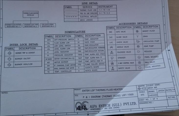
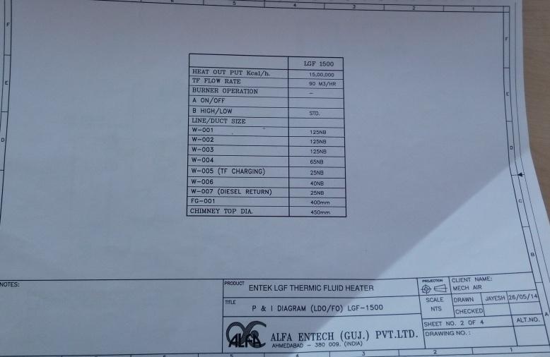
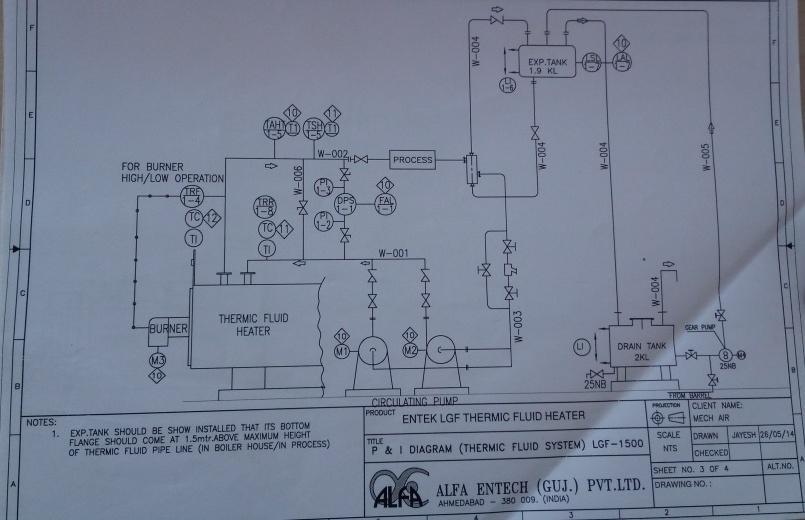
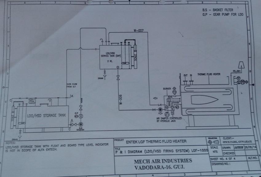
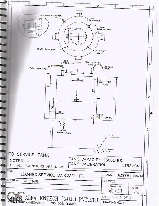
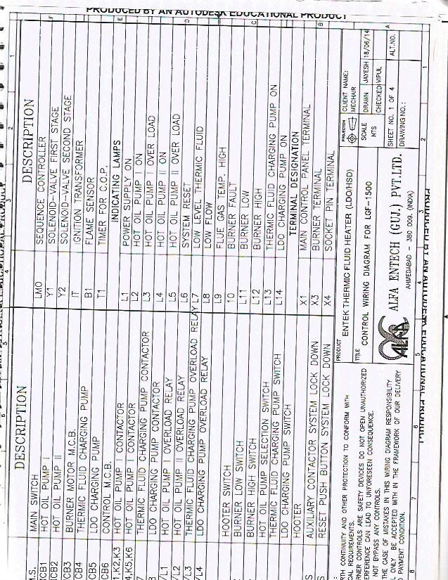
11 6 Pressure D stoner 7 Bucket Elevator Counter bearing for drive shaft 6204 Bearing for spring flate 6204 Bearing for main m/c drive 2215K V belt for m/c drive B72 Flate spring STD Rubber ball 30 mm dia counter weight drive bushes M12*36mm dia*38 mm Shose drive bushes M12*36 mm dia*38 mm Front post bushes M12*36 mm dia*38 mm Rear post bushes M12*36 mm dia*38 mm V belt B-44 Counter bearing for drive shaft UCF 205 Head pulley drive bearing UCF 205 Boot pulley drive bearing UCF 205 V belt motor to cwt A 65 V belt cwt to pulley A 59 Thermic Fluid Heater: SL. No Make Machine name Details 1 2 Alfa entech pvt ltd Alfa entech pvt ltd Boiler( Thermic Fluid Heater) Recirculation pump for boiler TYPE:Entek HSD/LDO thermic fluid boiler.model 1500 CAPACITY: KCAL/HR Out let temp. 300 degree calcious thermic fluid recommended HYTHERM 500 TYPE:Etanorm SYT SYT8 KSB order number: /01 Flow rate: Q 160 Mtr.cube/H Speed:n 2970 Kinetic viscosity:v 16.5 mn2/s Head: 77 mtr
12
13
14
 FOR TUBER LINE- PID FEEDING SIDE")
15 5 STAGE IMPERIAL DRYER (CONTINUOUS BELT DRYER) FOR TUBER LINE- PID FEEDING SIDE
 FOR TUBER LINE- PID OUTLET")
16 5 STAGE IMPERIAL DRYER (CONTINUOUS BELT DRYER) FOR TUBER LINE- PID OUTLET SIDE

17 HOT AIR CONVEYOR FOR TUBER LINE- PID

18 TRAY DRYER FOR CHILLI LINE- PID

19 TRAY DRYER FOR SEED LINE- PID
20
21
22
23
24
25
26
27
28
29
30
31
32
33
34
35
36
37
38
39
40
41
42

43
44
45
46
47
48
49
50
51
52
53 Installation- and maintenance instruction B70-2FH
54


55 DESCRIPTION , COMPONENTS 1. Flame cone 2. Shrouded disc 3. Nozzle 4. Nozzle assembly 5. Ignition electrodes 6. Ignition cable 7. Ignition transformer 8. Photoresistor 9. Control box 10. Front plate, relay base 11. Switch l-ll 12. Indicating lamp Stage Cover, inspection glass 14. Indicating lamp Stage Switch 0-l 17. Electric panel 18. Contactor 19. Thermal overload protection 20. Motor 21. Locking device, flange 22. Solenoid valves 23. Connecting pipe pump-solenoid valve bloc 24. Air intake 25. Solenoid valve bloc 26. Nozzle assembly adjustment 27. Scale, air regulation 28. Connecting pipe, solenoid valve bloc-adjustment device 29. Air damper 30. Pump 31. Adjustment device
56 TECHNICAL DATA Type designation B 70-2FH DIMENSIONS 408 ø220 ø B 730 Length of burner tube Flange Measure B Burner head Standard Burner head Long design OUTPUT RANGE AND NOZZLES RECOMMENDED Oil capacity Output Recommended nozzle Recommended kg/h kw Mcal/h Angle Danfoss Monarch Pump pressure Burner head B PLP 14 bar The net calorific value of 11,86 kwh/kg for light oil has been used. RECOMMENDED NOZZLE Because of different boiler types existing on the market, with varying combustion chamber designs, it is not possible to state a definite spray angle or spray pattern. Note that the spray angle and the spray pattern change with the pump pressure. BURNER HEAD 10,0-13,0 3,5-4,0 2,0-3,0 8,0-10,
57 TECHNICAL DATA DIMENSIONS OF FLANGE 14 (ø310)ø ø205,
58 GENERAL INSTRUCTIONS GENERAL RULES The installation of an oil burner should be carried out in accordance with local regulations. The installer of the burner must therefore be aware of all regulations relating to oil and combustion. Only oil suitable for the burner should be used and then in combination with a suitable oil filter before the oil pump of the burner. If the burner is replacing an existing burner make sure that the oil filter is replaced or cleaned. The installation must only be undertaken by experienced personnel. INSTALLATION INSTRUCTIONS General installation instructions accompany the burner and should be left in a prominent place adjacent to the burner. ADJUSTMENT OF BURNER The burner is from the factory pre-set to an average value that must then be adjusted to the boiler in question. All burner adjustments must be made in accordance with boiler manufacturers instructions.these must include the checking of flue gas temperatures, average water temperature and CO 2 or O 2 concentration. To adjust the combustion device, start by increasing the air volume and the nozzle assembly somewhat.when the burner starts it is burning with excess air and smoke number 0. Reduce the nozzle assembly adjustment until soot occurs, and then increase the adjustment to make the soot disappear again. Then the volume of air is reduced until soot occurs and increased again to reach a combustion free of soot. By this procedure an optimum adjustment is obtained. If larger nozzles are used the preadjustment of both the air volume and the nozzle assembly must be increased. A whistling sound may be heard which can be eliminated or reduced as follows: Increase the nozzle assembly adjustment somewhat. The CO 2 -content and consequently the air volume will then be reduced. CONDENSATION IN CHIMNEY A modern burner works with less excess air and often also with smaller nozzles than older models. This increases the efficiency but also the risk of condensation in the chimney. The risk increases if the area of the chimney flue is too large. The temperature of the flue gases should exceed 60 C measured 0,5 metres from the chimney top. Measures to raise the temperature: Insulate the chimney in cold attics Install a tube in the chimney Install a draught regulator (dilutes the flue gases during operation and dries them up during standstill) Increase the oil quantity Raise the flue gas temperature by removing turbulators, if any, in the boiler. PUMP ADJUSTMENT See separate description. MAINTENANCE The boiler/burner should be examined regularly for any signs of malfunction or oil leakage. OIL SUPPLY The oil line should be dimensioned in accordance with the pump manufacturer s instruction. In the suction line to the burner a filter should be mounted to prevent any particles in the oil from reaching the burner. If the installation consists of several burners each one should have its own suction line from the tank or a circulation system should be used. The temperature in the oil line should be kept as constant as possible. Avoid exposing the line to excessive cold which may cause blockages of paraffin deposits. The oil pipe and electric cable should be fitted so that the burner can be placed on the floor for inspection of the combustion device
 on low capacity (I).")
 on high capacity (II). Screw the knurled ring (B) in (reduce) or out (increase).")
59 GENERAL INSTRUCTIONS ADJUSTMENT OF NOZZLE ASSEMBLY Adjust the nozzle assembly with the adjustment screw D to the desired position. D AIR ADJUSTMENT First stage: Set the operating switch (S2) on low capacity (I). Loosen the screw (A) and turn the damper to the position wanted. Tighten the screw (A) again. Second stage: Set the operating switch (S2) on high capacity (II). Screw the knurled ring (B) in (reduce) or out (increase). The position of the damper can be read on the damper scale (C). Check the air adjustment by making a flue gas analysis. B A C
60 MAINTENANCE OF OIL BURNER Warning: Before doing any service switch off power at the main switch and cut off the oil supply. SERVICE OF BURNER HEAD NOTE! For maintenance of the brake plate, nozzles, electrodes etc, when using a long design of the burner tube, you have to remove the nozzle assembly from the connecting pipe and move the assembly backwards in the fan housing (from the boiler)
61 ELECTRIC EQUIPMENT OIL BURNER CONTROL: LMO B2B/LOA44 WIRING DIAGRAM LIST OF COMPONENTS A1 Oil burner control B1 Photoresistor F1 Operating fuse F2 Fuse F3 Fuse H1 Lamp, low capacity H2 Lamp, high capacity K1 Thermal overload protection M1 Burner motor S1 Operating switch S2 Operating switch, high/low capacity S3 Control thermostat S4 Temperature limiter S5 Micro switch for hinged door S6 Control thermostat, high/low capacity S7 Main switch S20 Main switch T1 Ignition transformer X1 Connection terminal board X2 Earth terminal X3 Plug-in contact "Euro", burner X4 Plug-in contact "Euro", boiler X5 Plug-in contact "Euro", high/low burner X6 Plug-in contact "Euro", high/low boiler X7 Plug-in contact "Euro" 3-phase, burner X8 Plug-in contact "Euro", 3-phase, boiler Y0 Solenoid valve start Y1 Solenoid valve 1 Y2 Solenoid valve 2 If S6 is missing connection between T6 and T8. Mains connection and fuse in accordance with local regulations. 3N~50/60Hz 400 V
62 ELECTRIC EQUIPMENT OIL BURNER CONTROL: LMO B2B FUNCTION 1. Switch on operating switch and twin thermostat The burner motor starts, an ignition spark is formed, the prepurge goes on till the prepurge period expires and the solenoid valve 1 opens (2). 2. Solenoid valve 1 opens Oil mist is formed and ignited. The photocell indicates a flame. 3. The safety time expires a. If no flame is established before this time limit the control cuts out. b. If for some reasons the flame disappears after this time limit, the burner will make an attempt to re-start. 4. Full load thermostat ON The burner is in operating position and can now change between high and low capacity Operating position If the burner operation is interrupted by means of the main switch or the thermostat, a new start takes place when the conditions in accordance with point 1 are fulfilled. The oil burner control cuts out A red lamp in the control is lit. Press the reset button and the burner re-starts. TECHNICAL DATA Pre-ignition time: 25 s Pre-purge time: 25 s Post-ignition time: 5 s Safety lock-out time: 5 s Reaction time on flame failure: max. 1 s Ambient temperature: from - 20 to +60 C Min. current with flame established: 30 µ A Max. photo current at start: 5,5 µ A Enclosure: IP 40 CONTROL OF PHOTO CURRENT Current through photo unit is measured with a d.c. ammeter (a moving coil instrument connected in series with the photo unit)


63 INSTRUCTIONS PUMP TYPE DANFOSS RSA 125 TECHNICAL DATA Viscosity range: 1,3-18,0 mm 2 /s Pressure range: 12,0-21,0 bar Oil temperature: -10 to +70 C COMPONENTS 1.Pressure gauge port G 1/8" 2.Nozzle port G 1/8" 3.Suction line G 1/4" 4.Suction line G 1/4" 5.Return line G 1/4" 6.Return line R 1/4" 7.By-pass plug 8.Pressure adjustment, 5 mm allen key SUCTION LINE TABLES The suction line tables consist of theoretically calculated values where the pipe dimensions and oil velocity have been matched so that turbulences will not occur. Such turbulences will result in increased pressure losses and in acoustic noise in the pipe system. In addition to drawn copper piping a pipe system usually comprises 4 elbows, a non-return valve, a cut-off valve and an external oil filter. The sum of these individual resistances is so insignificant that they can be disregarded. The tables do not include any lengths exceeding 100 m as experience shows that longer lengths are not needed. The tables apply to a standard fuel oil of normal commercial quality according to current standards. On commissioning with an empty tube system the oil pump should not be run without oil for more than 5 min. (a condition is that the pump is being lubricated during operation). The tables state the total suction line length in metres at a viscosity of 6,0 mm 2 /s. PURGING On 1-pipe systems it is necessary to purge the pump. On 2-pipe systems purging is automatic through the return line. H 1-pipe system Height Pipe diameter H ø10mm ø12mm ø15mm ø20mm m m m m m With an overlying tank a 1-pipesystem is not recommended Two-pipe system Height Pipe diameter H ø10mm ø12mm ø15mm ø20mm m m m m m 4, , , , , , , , H 1-pipe system Height Pipe diameter H ø10mm ø12mm ø15mm ø20mm m m m m m With an underlying tank a 1-pipesystem is not recommended Two-pipe system Height Pipe diameter H ø10mm ø12mm ø15mm ø20mm m m m m m , , , , , , , ,


64 FUNCTION DANFOSS RSA When the pump is started oil is drawn through the suction port "S" via filter "H" to the suction side of the gearwheel set "C". From here the gearwheel set pumps the oil to the pressure side and at the same time the oil becomes pressurized. The oil is led to cut-off and regulating valve "V" which opens when the set pressure is reached. The pressure is controlled and kept constant by regulating valve "V". At the same time the gearwheel set "C" distributes the oil through nozzle port "P" and pump return side "R" via the shaft seal "F". The quantity of oil supplied to nozzle port "P" is determined by the pressure set on regulating valve "V" and the nozzle/resistance in the nozzle line. In 2-pipe-systems excess oil is led back to the oil tank. In 1-pipe-systems the by-pass plug "A" must be removed to give free flow back to the suction side via return line "G" with return port "R" closed. When the pump is stopped, the pump S R output drops and produces a drop in the oil pressure. The spring in the regulating valve presses the regulating piston forward until it seals in port "P". This cuts off the oil flow to the nozzle and ensures that the nozzle line is effectively shut off. If the pump is overloaded, i.e. more oil is demanded than the gearwheel is able to pump under the given conditions, the oil pressure falls below the set value because the piston of the regulating valve moves towards its closed position and partially or wholly cuts off the return oil via port "O". This can be remedied by - reducing the pump pressure - reducing the capacity, i.e. smaller nozzle or greater resistance - changing to a pump with higher capacity MOUNTING/DISMOUNTING BY- PASS PLUG In a 2-pipe-system excess oil is led back direct to the oil tank. In a 1-pipesystem the by-pass plug must be removed so that there is a free passage back to the suction side through the return line with the return port closed. One pipe system EXCHANGE OF FILTER Two pipe system
65 FUNCTION FOR DANFOSS RSA 1. Nozzle 1 2. Nozzle 2 3. Nozzle 3 4. Solenoid valve Nozzle 1 5. Solenoid valve Nozzle 2 6. Solenoid valve Nozzle 3 and adjustment of air Stage 2 7. Oil pump 8. Air adjustment Stage 2 N.B. Nozzle 1+2= 1 st Stage Nozzle 1+2+3= 2 nd Stage
66 NOZZLE TABLE Pump pressure bar Gph kg/h kw Mcal/h kg/h kw Mcal/h kg/h kw Mcal/h kg/h kw Mcal/h kg/h kw Mcal/h kg/h kw Mcal/h kg/h kw Mcal/h kg/h kw Mcal/h 1,00 3, , , , , , , , ,10 4, , , , , , , , ,20 4, , , , , , , , ,25 4, , , , , , , , ,35 5, , , , , , , , ,50 5, , , , , , , , ,65 6, , , , , , , , ,75 6, , , , , , , , ,00 7, , , , , , , , ,25 8, , , , , , , , ,50 9, , , , , , , , ,75 10, , , , , , , , ,00 11, , , , , , , , ,50 13, , , , , , , , ,00 14, , , , , , , , ,50 16, , , , , , , , ,00 18, , , , , , , , ,50 20, , , , , , , , ,00 22, , , , , , , , ,50 24, , , , , , , , ,00 26, , , , , , , , ,50 27, , , , , , , , ,00 29, , , , , , , , ,50 31, , , , , , , , ,00 33, , , , , , , , ,50 35, , , , , , , , ,00 37, , , , , , , , ,00 40, , , , , , , , ,00 44, , , , , , , , ,00 52, , , , , , , , ,00 59, , , , , , , , ,00 67, , , , , , , , ,00 74, , , , , , , , ,00 81, , , , , , , , ,00 89, , , , , , , , ,00 96, , , , , , , , The table applies to oil with a viscosity of 4,4 mm 2 /s (cst) with density 830 kg/m
67 Situation FAULT LOCATION BURNER FAILS TO START Possible causes Remedies Motor runs Flame instabillity Burner pre-purges Flame occurs Burner locks out Motor runs Burner pre-purges No flame occurs Burner locks out Incorrect head settings Low oil pressure Excess air Photocell not seeing light Photocell failed Control faulty False light No spark No oil Check nozzle to burner head dimension and electrode position Check oil pressure Adjust air damper Check that photocell is clean and unobstructed Confirm with new photocell Confirm with new control. (NB. it is advisable to change the photocell if also changing control) Check that photocell is not seeing ambient light Check that H.T. leads are sound and are not arcing other than at electrode gap Check oil supply to burner - check that pump is not airlocked Check operation of magnetic valve BURNER FAILS TO START AFTER NORMAL OPERATION Burner fails to start Lamp not lit Fuse has blown Appliance thermostat has not reset Appliance overheat device has operated Control relay or photocell defective Check or replace fuse if necessary. Check reason for failure Adjust thermostat Reset overheat device. Find reason for its operation and rectify Check by replacement Motor runs Burner runs to lockout No oil being delivered Excessive flue draught is preventing flame establishment No spark Check that tank, oil lines, fire valve, pump and nozzle are all in good order Rectify condition Check ignition transformer. Check electrode gap and porecelains DELAYED IGNITION, BURNERS STARTS VIOLENTLY Burner pulsates on start-up only with hot flue Excessive draught Recommission burner Burner pulsates on start-up Nozzle partly blocked Replace nozzle Oil pressure too low Check and recommission Flue blocked or damaged Check and rectify Fan slipping on shaft Check and retighten Pump coupling loose or worn Check and replace Burner starts violently Delayed ignition Check the electrode adjustment, see diagram Check electrodes for damage Check H.T. leads for damage and disconnection
Providing sustainable energy solutions worldwide. Installation- and maintenance instruction MOL1650 T3N 323 2FH.
 178 024 63-2 2016-11-22 Providing sustainable energy solutions worldwide Installation- and maintenance instruction MOL1650 T3N 323 2FH No control DISCRIPTION Components 2 3 4 5 6 7 8 9 18, 19 13 10 17
Installation & Maintenance Manual
 Installation & Maintenance Manual MOL 200 S1L (B30A) Oil Burner 11/12 Tel: +44 (0) 1905 794331 Fax: +44 (0) 1905 794017 Email: info@nu-way.co.uk Web: www.nu-way.co.uk DESCRIPTION COMPONENTS 1. Shrouded
ST 40 Oil Burner. Installation & Maintenance Manual
 ST 40 Oil Burner Installation & Maintenance Manual 178 093 13 Thank you for choosing a Nu-way burner. As you would expect from a Company who has a pedigree of more than 75 years in the heating industry,
Providing sustainable energy solutions worldwide. Installation- and maintenance instruction B 30 A
 178 038 51-2 2016-07-08 Providing sustainable energy solutions worldwide Installation- and maintenance instruction B 30 A DESCRIPTION Components 1. Shrouded disc 2. Nozzle 3. Ignition electrodes 4. Nozzle
Providing sustainable energy solutions worldwide. Installation- and maintenance instruction B 45A
 178 017 55-1 2016-05-19 Providing sustainable energy solutions worldwide Installation- and maintenance instruction B 45A DESCRIPTION Components 1. Flame cone 2. Ignition electrodes 3. Nozzle assembly
Providing sustainable energy solutions worldwide. Installation- and maintenance instruction B 10 E R
 178 013 03-2 2016-05-26 Providing sustainable energy solutions worldwide Installation- and maintenance instruction B 10 E R DESCRIPTION Components 1. Scale, nozzle assembly 2. Nozzle assembly adjustment
Providing sustainable energy solutions worldwide. Installation- and maintenance instruction B 45 A2.2
 178 005 56-3 2017-10-11 Providing sustainable energy solutions worldwide Installation- and maintenance instruction B 45 A2.2 2 Bentone 1. Table of contents 1. Viktigt att tänka på! 4 2. Installation 7
Installation & Maintenance Manual
 Installation & Maintenance Manual Series SD fully automatic oil burners Selectos SD170 Oil Burner Tel: +44 (0) 1905 794331 Fax: +44 (0) 1905 794017 Email: info@nu-way.co.uk Web: www.nu-way.co.uk IMPORTANT
Installation and operating instructions B1FUV Classic
 Installation and operating instructions B1FUV Classic 1 171 135 10 05-02 178 033 31 Contents 01. GENERAL... 5 Description... 5 Declaration of conformity... 6 Safety directions... 7 02. TECHNICAL DATA...
Installation and operating instructions B2KSV Classic
 Installation and operating instructions B2KSV Classic 1 171 135 26 05-01 178 044 33 Contents 01. GENERAL... 5 Description... 5 Declaration of conformity... 6 Safety directions... 7 02. TECHNICAL DATA...
INSTRUCTION MANUAL FOR OIL BURNER MODELS
 INSTRUCTION MANUAL FOR OIL BURNER MODELS X500-2 Low voltage 12v dc Brushed motor E90-803-001-005-01 Rev 4-1 - Contents Technical specifications Technical data...3 Working field...3 Dimensions...4 Head
INSTRUCTION MANUAL FOR OIL BURNER MODELS
 INSTRUCTION MANUAL FOR OIL BURNER MODELS X500 Bio B10 E90-803-001-001-00 Rev 7-1 - Contents Technical specifications Technical data... 3 Working field... 3 Dimensions... 4 Head and electrode settings...
INSTRUCTION MANUAL FOR OIL BURNER MODELS
 INSTRUCTION MANUAL FOR OIL BURNER MODELS X400 Bio B10 E90-803-001-001-03 Rev 13-1 - Contents Technical specifications Technical data... 3 Working field... 3 Dimensions... 4 Head and electrode settings...
Oil TRIANCO. EuroStar Range BURNER DETAILS TRIANCO - OIL BURNER. To be retained by householder
 TRIANCO Oil TRIANCO - OIL BURNER BURNER DETAILS EuroStar Range To be retained by householder TECHNICAL DATA NOZZLE OUTPUT MODEL Output Burner Nozzle Pump Model pressure CO 2 (%) EUROSTAR UTILITY 50/65
Light oil burners. One stage operation
 Installation, use and maintenance instructions Light oil burners One stage operation CODE MODEL TYPE 3505 RDB CF 38 50 T3 350050 RDBR CF 6 50 TR 35050 RDBR CF 33 50 TR 35050 RDBR CF 38 50 T3R 350650 RDBR
Single stage operation oil burner
 Installation & Operating Manual Single stage operation oil burner WARNING NON-RETROFIT APPLICATIONS If this burner is being installed in a packaged unit (ie. burner comes with a boiler or furnace), follow
Single stage operation oil burner
 Installation & Operating Manual Single stage operation oil burner WARNING NON-RETROFIT APPLICATIONS If this burner is being installed in a packaged unit (ie. burner comes with a boiler or furnace), follow
Parts Available from
 Montage und Bedienungsanleitung Manuel d entretien Installation, use and maintenance instructions Installatie-, gebruiks- en onderhoudsvoorschriften Oδηγίες εγκατάστασης, χρήσης και συντήρησης D F GB NL
Providing sustainable energy solutions worldwide. Installation- and maintenance instruction B 70-2/3
 178 001 63 Providing sustainable energy solutions worldwide Installation- and maintenance instruction B 70-2/3 DESCRIPTION Components 1. Flame cone 2. Shrouded disc 3. Nozzle 4. Nozzle assembly 5. Ignition
Oil burners Brûleurs fioul Stookoliebranders
 Installation, use and maintenance instructions Manuel d entretien Installatie-, gebruiks- en onderhoudsvoorschriften GB F NL Oil burners Brûleurs fioul Stookoliebranders One stage operation Fonctionnement
Light oil - kerosene burner
 Installation, use and maintenance instructions Light oil - kerosene burner One stage operation CODE MODEL TYPE 374374 G3B 437T 90 (4) - 05/0 TECHNICAL FEATURES TYPE 437T Thermal power output 9 35 kw.6
RL/1 SERIES. One Stage Light Oil Burners FIRING RATES LIGHT OIL RL 34/1 MZ kw
 The RL/1 burners series covers a firing range from 107 to 398 kw, and it has been designed for use in low or medium temperature hot water boilers, hot air or steam boilers, diathermic oil boilers. Optimisation
Providing sustainable energy solutions worldwide. Installation- and maintenance instruction B 30 A
 178 088 51-1 2016-04-14 Providing sustainable energy solutions worldwide Installation- and maintenance instruction B 30 A DESCRIPTION Components 1. Shrouded disc 2. Nozzle 3. Ignition electrodes 4. Nozzle
15 20 kw kw kw
 Burner Set-up Details 15 20 kw 20 26 kw 29 36 kw Riello RDB2 Please read these instructions carefully before commissioning and using this appliance. To be retained by the householder HEALTH AND SAFETY
RETROFIT APPLICATIONS ONLY
 Installation & Operating Manual WARNING RETROFIT APPLICATIONS ONLY If this burner is being installed in a packaged unit (ie. burner comes with a boiler or furnace), follow the installation and set-up instructions
Forced draught gas burner
 Installation, use and maintenance instructions Forced draught gas burner Code Model Type 3751982 GAS 3 519T80 291 (3) - 02/2010 DECLARATION Declaration of conformity in accordance with ISO / IEC 17050-1
Oil burners fuel unit with solenoid valve
 Oil burners fuel unit with solenoid valve Type VM www.deltapumps.com VM1 - VM4U flanged Certified Quality System Printed in Italy - DE112/0404 Oil burners fuel unit with solenoid valve Type VM The DELTA
Oil burners fuel unit with solenoid valve
 Oil burners fuel unit with solenoid valve Type VM www.deltapumps.com VM1 - VM4U flanged Certified Quality System Printed in Germany VM_e.pdf - 18.05.08 Page 1/6 Oil burners fuel unit with solenoid valve
Providing sustainable energy solutions worldwide. Installation- and maintenance instruction BENTOFLEX ST120KA
 178 009 15-1 2016-04-27 Providing sustainable energy solutions worldwide Installation- and maintenance instruction BENTOFLEX ST120KA DESCRIPTION Components 1. Reset button 2. Control box 3. Ignition transformer
Forced draught gas burner
 Installation, use and maintenance instructions GB Forced draught gas burner One stage operation CODE MODEL TYPE 3751782 GAS 5 517T80 291 (4) - 07/2015 Declaration of conformity in accordance with ISO /
Light oil / kerosene burner
 Installation, use and maintenance instructions Light oil / kerosene burner One stage operation CODE MODEL TYPE 374445 G5 444T50 290238 (5) - 05/20 TECHNICAL DATA Thermal power output 28 60 kw 2.3 5 kg/h
Heating, Air Conditioning, Ventilation. Отопление-Кондиционеры-Вентиляция. MTM 8-30 kw UNIVERSAL OIL HEATER OPERATING MANUAL
 Heating, Air Conditioning, Ventilation Отопление-Кондиционеры-Вентиляция MTM 8-30 kw UNIVERSAL OIL HEATER OPERATING MANUAL 1. Usage MTM 8-30 universal oil heater is designed for heating commercial rooms
CODE MODEL TYPE PRESS 60 N 616 T PRESS 60 N 616 T80
 Installation, use and maintenance instructions Heavy oil burner CODE MODEL TYPE 3434985 PRESS 60 N 616 T80 3434986 PRESS 60 N 616 T80 291 (2) - 01/2009 Thermal power - Output Operation Fuel Electrical
A AD Oil burners fuel unit. deltapumps.com. DE A-AD_en_0709.pdf Page 1/1
 A AD Oil burners fuel unit deltapumps.com DE116-0709 A-AD_en_0709.pdf - 16.11.09 Page 1/1 Oil burners fuel unit Type A, AD 1- Applications The DELTA aluminium fuel unit type A is an efficient and modern
Single stage operation oil burners
 Installation & Operating Manual Single stage operation oil burners WARNING RETROFIT APPLICATIONS ONLY If this burner is being installed in a packaged unit (ie. burner comes with a boiler or furnace), follow
DF400/DF600. Construction Heaters. Installation and Maintenance Manual
 342 N. Co. Rd. 400 East Valparaiso, IN 46383 219-464-8818 Fax 219-462-7985 www.heatwagon.com Installation and Maintenance Manual Please retain this manual for future reference. DF400/DF600 Construction
RETROFIT APPLICATIONS ONLY
 Installation & Operating Manual Single stage operation oil burners RETROFIT APPLICATIONS ONLY If this burner is being installed in a packaged unit (ie. burner comes with a boiler or furnace), follow the
Indirect gas-fired air heater
 Indirect gas-fired air heater SERIES HD INSTALLATION AND SERVICE MANUAL MANUFACTURED BY : BROTHERS LIMITED WARNING Improper installation, modification, adjustment or maintenance may cause damage, injury
Providing sustainable energy solutions worldwide. Installation- and maintenance instruction B 30 A
 178 028 51 Providing sustainable energy solutions worldwide Installation- and maintenance instruction B 30 A DESCRIPTION Components 1. Shrouded disc 2. Nozzle 3. Ignition electrodes 4. Nozzle assembly
Internal ridged board 1" x 1.5 foil face installation shall be installed on roof, walls and base of casing.
 A-D WITH MPU SPECIFICATION WRITTEN SPECIFICATION Description A Modular Packaged Heating, Cooling and ventilating unit(s), as indicated on the drawings shall be furnished. Direct Fired Gas Unit(s) shall
TWO STAGE HEAVY OIL BURNERS
 TWO STAGE HEAVY OIL BURNERS PRESS N SERIES PRESS 30 N 85/171 342 kw PRESS 45 N 114/205 513 kw PRESS 60 N 171/342 684 kw PRESS 100 N 285/490 1140 kw The PRESS N series of burners covers a firing range from
Universal fuel unit for oil burners
 Universal fuel unit for oil burners Type U www.deltapumps.com European patent Certified Quality System rinted in Italy - DE115/0404 Universal Fuel Unit for oil burners Type U The DETA Universal Fuel Unit
OPERATING INSTRUCTIONS MANUAL (Please retain for future reference) FVO-200 INDIRECT FIRED SPACE HEATERS
 FVO-200 INDIRECT FIRED SPACE HEATERS") OPERATING INSTRUCTIONS MANUAL (Please retain for future reference) For FVO-200 INDIRECT FIRED SPACE HEATERS CERTIFIED FOR USE IN CANADA AND U.S.A. As per CSA B140.8 Portable Oil Fired Heaters / CSA B140.02003
OPERATING INSTRUCTIONS MANUAL (Please retain for future reference) For FVO-200 INDIRECT FIRED SPACE HEATERS CERTIFIED FOR USE IN CANADA AND U.S.A. As per CSA B140.8 Portable Oil Fired Heaters / CSA B140.02003
OPERATION MANUAL KP4041 POLY SCRAP COMPACTOR
 OPERATION MANUAL KP4041 POLY SCRAP COMPACTOR IBIS INTERNATIONAL Thank you for purchasing the KP4041 Poly Scrap Compactor. IBIS appreciates your confidence in our product, and promises to support its operation
en Direct oil-fired space heaters HD... Operator's manual
 0211670en 002 12.2007 Direct oil-fired space heaters HD... Operator's manual Table of contents 1. Foreword 5 2. Safety information 6 2.1 General recommendations... 6 2.2 Safety devices... 7 2.3 Labels...
OPERATING & MAINTENANCE MANUAL INDUSTRIAL DIRECT FIRED DIESEL/KEROSENE HEATERS IC 25
 OPERATING & MAINTENANCE MANUAL INDUSTRIAL DIRECT FIRED DIESEL/KEROSENE HEATERS IC 25 NOT FOR DOMESTIC USE SPACE HEATING ONLY Made By: Spitwater Australia Pty Ltd 953 Metry St North Albury, NSW, Australia
FLAME115 INFRARED HEATER SERVICE MANUAL INDEX FIRE 115 WARNING
 FLAME115 INFRARED HEATER SERVICE MANUAL INDEX 1. CONTROLS AND COMPONENTS 2. FLAME CONTROL CYCLES 3. MAINTENANCE SCHEDULE 4. TROUBLESHOOTING GUIDE 5. REPAIR PROCEDURES 1. FAN MOTOR ASSEMBLY 2. FUEL FILTER
ANNEXURE-A SPECIFICATIONS FOR HOT MIX PLANT
 ANNEXURE-A SPECIFICATIONS FOR HOT MIX PLANT COLD AGGREGATE BIN FEEDER FEEDING HOPPERS Four Nos. Cold aggregates hopper with a heaped capacity of approx. 52 T. Wide opening bin width to accommodate different
Installation & Service Instructions for Jackson & Church Flexaire Packaged Furnaces SDF-125 thru SDF-400 Gas Firing
 Installation & Service Instructions for Jackson & Church Flexaire Packaged Furnaces SDF-125 thru SDF-400 Gas Firing Important: To protect the unit and avoid damage to the heat exchanger, the blower speed
OPERATING INSTRUCTIONS MANUAL (Please retain for future reference) FVO-200 INDIRECT FIRED SPACE HEATERS
 FVO-200 INDIRECT FIRED SPACE HEATERS") OPERATING INSTRUCTIONS MANUAL (Please retain for future reference) For FVO-200 INDIRECT FIRED SPACE HEATERS CERTIFIED FOR USE IN CANADA AND U.S.A. As per CSA B140.8 Portable Oil Fired Heaters / CSA B140.02003
OPERATING INSTRUCTIONS MANUAL (Please retain for future reference) For FVO-200 INDIRECT FIRED SPACE HEATERS CERTIFIED FOR USE IN CANADA AND U.S.A. As per CSA B140.8 Portable Oil Fired Heaters / CSA B140.02003
Direct Fired Heater Model AD Specification
 Direct Fired Heater Model AD Specification Description A Direct-fired gas heating and ventilating unit(s), as indicated on the drawings shall be furnished. Unit(s) shall be tested in accordance with ANSI
POWDER GUIDE. Trouble shooting tips to maximise the benefits of Apcoshield Powder Coatings
 POWDER GUIDE From ASIAN PAINTS (I) LTD Trouble shooting tips to maximise the benefits of Apcoshield Powder Coatings Section A : Powder Application Problems Trouble Possible Causes Solutions 1. Poor charging
JUMBO INDIRECT FIRED DIESEL HEATER OPERATING INSTRUCTIONS
 JUMBO INDIRECT FIRED DIESEL HEATER OPERATING INSTRUCTIONS Before using the heater, read and understand all instructions and follow them carefully. The manufacturer is not responsible for damages to goods
DH-Direct Fired Poultry Farm Diesel Heater
 DH-Direct Fired Poultry Farm Diesel Heater Comparison of Diesel Heater to Gas Heater Diesel LPG Gas LPG Gas KW 43 70 120 Fuel consumption/hr 3 5.1 8.8 Heat output 37000 60000 100000 Cost of fuel/lit or
product Industrial burners Industrial burners sizes 30 to 70 flexible and reliable Information on oil, gas and dual fuel burners
 product Information on oil, gas and dual fuel burners Industrial burners Industrial burners sizes to flexible and reliable Weishaupt Industrial Burners: Flexible and reliable For more than years, Weishaupt
Model 601CRD Oil Burner
 Model 601CRD Oil Burner Installation and Operating Instructions For Use By Qualified Service Technicians Only CRD burners feature a combustion head incorporating a new design concept which provides a means
E q KESHAR. Product Range : Asphalt Stationary Drum Mix Plant. Wet Mix Macadam Plant. Asphalt Mobile Drum Mix Plant.
 Value added added Machines Machines with with High Quality & Latest & Latest Technology Technology Asphalt Stationary Drum Mix Plant Qua t li y R o a d Construction Wet Mix Macadam Plant Asphalt Mobile
Flame115 Radiant. Flame115 Specifications. Flame115 Accessories
 PORTABLE HEATERS Whether you re curing concrete, warming equipment or heating spaces, you ll work faster and smarter with Veloci portable heaters. Our versatile, Italian-engineered radiant and forced-air
SERVICE AND INSTALLATION MANUAL MODELS HDO(H) OIL FOR YOUR SAFETY
 OIL FOR YOUR SAFETY") Bousquet Technologies Inc. 2121, Nobel, Ste Julie, Quebec, Canada, J3E1Z9 SERVICE AND INSTALLATION MANUAL MODELS HDO(H) OIL Oil-Fired air heater for industrial and commercial use. FOR YOUR SAFETY Do not
Bousquet Technologies Inc. 2121, Nobel, Ste Julie, Quebec, Canada, J3E1Z9 SERVICE AND INSTALLATION MANUAL MODELS HDO(H) OIL Oil-Fired air heater for industrial and commercial use. FOR YOUR SAFETY Do not
Replacement Parts List For Models COS-20G
 Replacement Parts List For Models COS-20G (Ovens with s/n HP & HT) Contents: Page # Electrical Compartment:Contactors,Steam Generator,Thermostats 2-5 Oven Interior: 5 Bottom Section: Gas, Plumbing Components
Garb-el Free Standing Models
 Garb-el Products Company Promoting Environmental Responsibility Since 1950 Garb-el Free Standing Models Installation, Operation & Maintenance Manual Garb-el Products Company 240 Michigan Street Lockport,
DUOBLOCK DUAL FUEL (GAS-HEAVY OIL) BURNERS INSTALLATION, OPERATING AND MAINTENANCE MANUAL
 BURNERS INSTALLATION, OPERATING AND MAINTENANCE MANUAL") DUOBLOCK DUAL FUEL (GAS-HEAVY OIL) BURNERS INSTALLATION, OPERATING AND MAINTENANCE MANUAL MODULATING OPERATION ECO 250 ECO 300 ECO 350 ECO 400 ECO 450 ECO 500 ECO 600 ECO 700 ECO 800 ECO 900 www.ecostar.com.tr
DUOBLOCK DUAL FUEL (GAS-HEAVY OIL) BURNERS INSTALLATION, OPERATING AND MAINTENANCE MANUAL MODULATING OPERATION ECO 250 ECO 300 ECO 350 ECO 400 ECO 450 ECO 500 ECO 600 ECO 700 ECO 800 ECO 900 www.ecostar.com.tr
Cleaning unit for coolant. :_decftez`_>r_fr] Book No.: V2
![Cleaning unit for coolant. :_decftez`_>r_fr] Book No.: V2](/thumbs/90/104143238.jpg "Cleaning unit for coolant. :_decftez`_>r_fr] Book No.: V2") Cleaning unit for coolant :_decftez`_>r_fr] Book No.: 1271526-02 V2 Alfa Laval Separation AB Separator Manuals, dept. SKEL S-147 80 Tumba, Sweden Telephone: +46 8 53 06 50 00 Telefax: +46 8 53 03 10 40
Cleaning unit for coolant :_decftez`_>r_fr] Book No.: 1271526-02 V2 Alfa Laval Separation AB Separator Manuals, dept. SKEL S-147 80 Tumba, Sweden Telephone: +46 8 53 06 50 00 Telefax: +46 8 53 03 10 40
ATMOSPHERIC GAS BOILER INSTALLATION, OPERATING AND MAINTENANCE MANUAL
 STREBEL GENEVA CE ATMOSPHERIC GAS BOILER INSTALLATION, OPERATING AND MAINTENANCE MANUAL INDEX TABLE 1 TECHNICAL DATA SECTION 1 SECTION 2 SECTION 3 SECTION 4 SECTION 5 SECTION 6 SECTION 7 SECTION 8 SECTION
RL 28/2-38/2-50/2 Low - High Operation
 Installation, use and maintenance instructions Light Oil Burners RL 28/2-38/2-50/2 Low - High Operation C6505050 CONTENTS WARNING TECHNICAL DATA..............................page 3 Burner models.....................................
OIL FIRED COOKERS & BOILERS
 REPLACEMENT PARTS 1. BOILER BURNER ECOFLAM PART NO A. COMMON PARTS Mounting Gasket 18.04.001 Oil Pump Danfoss BFP 11R3 0.0.000 Flexible Oil Line 740mm 1 /4 BSP Braided 01.0.300 Control Box Landis and GYR
Mikrofill Ethos Condensing combination boiler. Maintenance Instructions 24cc
 Mikrofill Ethos Condensing combination boiler Maintenance Instructions 24cc IMPORTANT Benchmark Installation, Commissioning and Service Record Log Book is enclosed in your customer information pack. This
TECHNICAL INSTRUCTIONS USE AND MAINTENANCE
 TECHNICAL INSTRUCTIONS USE AND MAINTENANCE Cm Pelet-set For boilers CentroPlus 25/35 and CentroPlus-B 25/35 (solid fuel and wood pellets fuel firing) TUPSCP-K-11-2016-ENG CONTENTS 1.Introduction 2. Status
INFRARED PARAFfIN / KEROSENE / model No: ir20.v2 1. SAFETY INSTRUCTIONS RECOMMENDED FUSE RATING: 5AMP
 InstructioNS for: INFRARED PARAFfIN / KEROSENE / diesel HEATER model No: ir20.v2 Thank you for purchasing a Sealey product. Manufactured to a high standard this product will, if used according to these
Infrared Diesel Heater
 Infrared Diesel Heater Model No: IRD40 PART NO: 6920415 OPERATING & MAINTENANCE INSTRUCTIONS GC0812 INTRODUCTION Thank you for purchasing this CLARKE Diesel Infrared Heater. Before attempting to use the
INTRODUCTION THIS MANUAL INCLUDES IMPORTANT SAFETY INFORMATION
 INSTALLATION AND OPERATING INSTRUCTIONS FOR THE HARDY Fuel Oil Furnace Models D-140 & D-350 HARDY MANUFACTURING COMPANY, INC. 12345 ROAD 505 PHILADELPHIA, MS 39350 PHONE: (601) 656-5866 FAX: (601) 656-4559
HORIZONTAL MULTISTAGE CENTRIFUGAL PUMP
 HORIZONTAL MULTISTAGE CENTRIFUGAL PUMP WWPPCHLFT260 Instructions WWPPCHLFT260_Horizontal Multistage Centrifugal Pump_IB.indd 1 READ THIS MANUAL CAREFULL BEFORE INSTALL, START THE PUMP 1. Suction 2. Plug
4VH and 4VHX. 4" Non-Clog Wastewater Pumps Standard (4VH) and Explosion-Proof (4VHX) Construction
 and Explosion-Proof (4VHX) Construction") 4VH and 4VHX 4" Non-Clog Wastewater Pumps Standard (4VH) and Explosion-Proof (4VHX) Construction DURABLE MOTOR WILL DELIVER MANY YEARS OF RELIABLE SERVICE Oil-filled motor for maximum heat dissipation
4VH and 4VHX 4" Non-Clog Wastewater Pumps Standard (4VH) and Explosion-Proof (4VHX) Construction DURABLE MOTOR WILL DELIVER MANY YEARS OF RELIABLE SERVICE Oil-filled motor for maximum heat dissipation
OPERATING INSTRUCTIONS MANUAL (Please retain for future reference) FVO-400 INDIRECT FIRED SPACE HEATERS
 FVO-400 INDIRECT FIRED SPACE HEATERS") OPERATING INSTRUCTIONS MANUAL (Please retain for future reference) For FVO-400 INDIRECT FIRED SPACE HEATERS CERTIFIED FOR USE IN CANADA AND U.S.A. As per CSA B140.8 Portable Oil Fired Heaters / CSA B140.02003
OPERATING INSTRUCTIONS MANUAL (Please retain for future reference) For FVO-400 INDIRECT FIRED SPACE HEATERS CERTIFIED FOR USE IN CANADA AND U.S.A. As per CSA B140.8 Portable Oil Fired Heaters / CSA B140.02003
OPERATING & MAINTENANCE MANUAL DC10 DC15 DC25 DC40 DC45
 OPERATING & MAINTENANCE MANUAL INDUSTRIAL DIRECT FIRED DIESEL/KEROSENE HEATERS DC10 DC15 DC25 DC40 DC45 Made By: NOT FOR DOMESTIC USE SPACE HEATING ONLY Spitwater Australia Pty Ltd 953 Metry St., North
Servicing manual. Wall-mounted condensing gas boiler 600 Series - 11S / 19S / 24S / 24C /2002 GB(EN) For trade use
 For trade use") GB122 7210 1300-12/2002 GB(EN) For trade use Servicing manual Wall-mounted condensing gas boiler 600 Series - 11S / 19S / 24S / 24C Please read thoroughly before attempting to diagnose fault List of contents
GB122 7210 1300-12/2002 GB(EN) For trade use Servicing manual Wall-mounted condensing gas boiler 600 Series - 11S / 19S / 24S / 24C Please read thoroughly before attempting to diagnose fault List of contents
Servicing manual. 600 Series - 11S / 19S / 24S / 24C. Wall-mounted condensing gas boiler. For trade use
 GB122 Servicing manual Wall-mounted condensing gas boiler 600 Series - 11S / 19S / 24S / 24C For trade use Please read thoroughly before attemting to diagnose fault 7217 4900 (03/2010) GB/IE List of contents
Hakki Pilke Raven spare parts manual
 1 ENGLISH Hakki Pilke Raven spare parts manual Valimotie 1, FI-85800 Haapajärvi, FINLAND Tel. +358 8 772 7300, Fax +358 8 772 732 info@maaselankone.fi, www.maaselankone.fi 2 Table of contents 1 Upper section
Grant UK VortexBlue. 21, 26 and 36kW Blue Flame Oil Boiler Range. Supplementary Installation, Servicing and User Instructions
 Grant UK VortexBlue 21, 26 and 36kW Blue Flame Oil Boiler Range Supplementary Installation, Servicing and User Instructions UK DOC 0108 Rev 1.1 April 2016 GRAT EGIEERIG (UK) LIMITED Hopton House, Hopton
MONOBLOCK HEAVY OIL BURNERS INSTALLATION, OPERATING AND MAINTENANCE MANUAL
 MONOBLOCK HEAVY OIL BURNERS INSTALLATION, OPERATING AND MAINTENANCE MANUAL ONE STAGE, TWO STAGE AND MODULATING OPERATION ECO 2 ECO 30 ECO 45 www.ecostar.com.tr DEAR USER, ECOSTAR ECO 2, ECO 30, ECO 45
DM 45 (40-60 TPH) ASPHALT DRUM MIX PLANT - DM 50 (60-90 TPH) I TECHNICAL SPECIFICATIONS DM 60 ( TPH) COLD AGGREGATE FEEDER.
 ASPHALT DRUM MIX PLANT - DM 50 (60-90 TPH) I TECHNICAL SPECIFICATIONS DM 60 ( TPH) COLD AGGREGATE FEEDER.") DM 45 (40-60 TPH) ASPHALT DRUM MIX PLANT - DM 50 (60-90 TPH) I TECHNICAL SPECIFICATIONS DM 60 (90-120 TPH) ROAD BUILDING COLD AGGREGATE FEEDER Stationary four bin cold aggregate feeder unit is with each
DM 45 (40-60 TPH) ASPHALT DRUM MIX PLANT - DM 50 (60-90 TPH) I TECHNICAL SPECIFICATIONS DM 60 (90-120 TPH) ROAD BUILDING COLD AGGREGATE FEEDER Stationary four bin cold aggregate feeder unit is with each
LATTNER BOILER COMPANY 9.5 HP Low-NOx Installation and Start-Up Checklist for Dry Cleaners
 1 1. General Installation Information (to be completed by technician) Date installed: Location (city & state): Cleaner s name: National Board number (boiler): Installed by (company): Installed by (technician):
AXIAL HEATER TROUBLE SHOOTING GUIDE. Models: AX24 N/PV, AX24 N/PV LT, AX24 LP AX26 N/PV, AX26 N/PV LT, AX26 LP AX28 N/PV, AX28 N/PV NT, AX28 LP
 AXIAL HEATER TROUBLE SHOOTING GUIDE Page 1 July 2009 Table of Contents Frequently Asked Questions... 3 Axial Heater CONTROL (Siemens LME69) Troubleshooting Chart... 4 Axial Heater BURNER Troubleshooting
MMG Gas burner safety control
 A Honeywell Company Gas burner safety control INTRODUCTION gas burner safety controls are suitable for fully automatic forced and induced draught gas burners which have an intermittent (expanding flame)
THC- 355DF (Dual Fuel)
") OPERATING INSTRUCTIONS MANUAL THC- 355DF (Dual Fuel) INDUSTRIAL / COMMERCIAL DIRECTIONAL SPACE HEATER (OPERATOR MUST RETAIN FOR FUTURE REFERENCES) Certified to / Certifié à ANSI std Z83.7 2000 Suitable
OPERATING INSTRUCTIONS MANUAL THC- 355DF (Dual Fuel) INDUSTRIAL / COMMERCIAL DIRECTIONAL SPACE HEATER (OPERATOR MUST RETAIN FOR FUTURE REFERENCES) Certified to / Certifié à ANSI std Z83.7 2000 Suitable
RL 70/2-100/2-130/2 Low - High Operation
 Installation, use and maintenance instructions Light Oil Burners RL 70/2-100/2-130/2 Low - High Operation C6505052 CONTENTS WARNING TECHNICAL DATA............................. page 3 Burner models.....................................
A. Section Common Motor Requirements for HVAC Equipment: Fan motors.
 SECTION 235533 - FUEL-FIRED UNIT HEATERS PART 1 GENERAL 1.1 SECTION INCLUDES A. Gas fired unit heaters. B. Oil fired unit heaters. C. Tubular infrared heaters. 1.2 RELATED REQUIREMENTS A. Section 230513
PRE-BATCHER UNIT DRYER UNIT. Model: RM 350. Year of construction: Composed of:
 Asphalt Plant INTRAME 350 RM Alicante, 24.10.2017 Asphalt Plant INTRAME 350 RM Offer number: A-160509-1994-01 Brand: INTRAME Model: RM 350 Capacity: 350 t/h Year of construction: 1994 Refurbished: 2004
MMI (40-34) Gas burner safty control
 Gas burner safty control") certified Qualitysystem ISO 9001 / EN 29001 A Honeywell Company Reg. Nr. 10529 (40-34) Gas burner safty control 0708.22-01-e/12/98 INTRODUCTION The Mod 40-34 gas burner safety control is suitable for fully
certified Qualitysystem ISO 9001 / EN 29001 A Honeywell Company Reg. Nr. 10529 (40-34) Gas burner safty control 0708.22-01-e/12/98 INTRODUCTION The Mod 40-34 gas burner safety control is suitable for fully
Effective october 14, 2014
 COS-20G combi oven-steamer REPLACEMENT PARTS LIST Effective october 14, 2014 Superseding All Previous Parts Lists. The Company reserves the right to make substitution in the event that items specified
INDIVIDUAL DRIVE, CHAIN DRIVE AND U- SEAL MECHANISM IN ROLLER HEARTH NORMALISING FURNACE
 INDIVIDUAL DRIVE, CHAIN DRIVE AND U- SEAL MECHANISM IN ROLLER HEARTH NORMALISING FURNACE Akash Kumar Mechanical Engineering Dronacharya College of Engg. Gurgaon, Haryana Abstract:- This project deals with
GAS GRIDDLE INSTRUCTIONS MODEL: PGF GRIDDLES PGF 300, 600, 800, 1200
 Page 1 of 17 GAS GRIDDLE INSTRUCTIONS MODEL: PGF GRIDDLES PGF 300, 600, 800, 1200 VALIDATE WARRANTY SAFETY INSTRUCTIONS INSTALLATION INSTRUCTIONS OPERATION INSTRUCTIONS MAINTENANCE INSTRUCTIONS CONVERSION
1. GENERAL SAFETY RULES
 ID180 & ID290 Indirect-Fired Diesel/Oil Construction Heaters Sure Flame Products Lethbridge, Alberta, Canada Telephone: (403)328-5353 Fax: (403)328-9956 www.sureflame.ca July 12, 2006 Service and Maintenance
TEMPRA. Wall Mounted Fan Flue System boiler. Wall mounted fanned flue boiler INSTALLATION AND USE INSTRUCTIONS. Appr. nr. B A - CE 0063 AQ 2150
 Wall Mounted Fan Flue System boiler Appr. nr. B 94.04 A - CE 0063 AQ 2150 Phone numbers: Installer Service Engineer Serial N Wall mounted fanned flue boiler INSTALLATION AND USE INSTRUCTIONS Please read
PARTS MANUAL. American Dish Service ADS CONVEYOR DISHWASHER MODELS: ADC-44 L-R/R-L EFFECTIVE: SEPTEMBER 1, 2001
 EFFECTIVE: SEPTEMBER 1, 2001 ADS CONVEYOR DISHWASHER MODELS: ADC-44 L-R/R-L PARTS MANUAL 900 Blake Street Edwardsville, Kansas 66111 (913)422-3700 211-0044L-R / 212-0044R-L ADC-44 Conveyor Dishwasher 2
100 FLUEBOOST
 100 FLUEBOOST f l u e b o o s t 1 0 0 The flueboost is a box shaped centrifugal fan unit with in line spigots for the flue connection, a pressure switch to ensure safe operation, all within a compact package.
REMKO CLK Mobile automatic heater
 REMKO CLK Mobile automatic heater Operation Technology Spare Parts Edition GB M04 REMKO - powerful like a bear. Operating Instructions Read these instructions carefully before setting up/operating the
MANUAL. OEM (Unit) OZONE GENERATOR (100VA, 200VA and 300VA) INDEX
 OZONE GENERATOR (100VA, 200VA and 300VA) INDEX") MANUAL OEM (Unit) OZONE GENERATOR (100VA, 200VA and 300VA) INDEX 1) Technical Specifications: (100VA, 200VA, 300VA) 2) Introduction 3) Construction 4) Operation and maintenance a) Operating Procedure b)
MANUAL OEM (Unit) OZONE GENERATOR (100VA, 200VA and 300VA) INDEX 1) Technical Specifications: (100VA, 200VA, 300VA) 2) Introduction 3) Construction 4) Operation and maintenance a) Operating Procedure b)
POWER VENTER SYSTEM. Model: PVO-300, PVO-600
 POWER VENTER SYSTEM Model: PVO-300, PVO-600 Included is one ETL and cetl listed Power Venter to be used primarily with a single 120VAC controlled oil fired furnace, boiler, or water heater. The PVO may
US Filtermaxx. 200,000 BTU Waste Oil Burner
 US Filtermaxx 200,000 BTU Waste Oil Burner Assemble the Burner: Remove all the parts from the box. Locate the burner flange coupling and attach it to the front of the burner as seen in the photo below