Installation and operating instructions
|
|
|
- Janel Thornton
- 6 years ago
- Views:
Transcription
1 Installation and operating instructions To be precise.
2 Installation and operating instructions Table of contents General notes Page Thermostatic valve 3 Faults Causes Remedial action 4 Temperature setting 5, 6 Installation Thermostatic head K 7 Thermostatic head DX 7 Thermostatic head D 7 Thermostatic head K with remote sensor 7 Thermostatic head K with theft protection 8 Thermostatic head WK 9 Thermostatic head VK 10 Thermostatic head VD 11 Thermostatic head B 12 Thermostatic head F 13, 14 Operation Marking, restricting or locking Thermostatic head K 15 Thermostatic head VK 15 Thermostatic head WK 15 Thermostatic head VD 16 Hidden restricting or locking Thermostatic head VD 16 Thermostatic head K 17, 18 Thermostatic head VK 17, 18 Thermostatic head F 19 Basic setting Thermostatic head K 20 Thermostatic head VK 20 Precision presetting or finest presetting V-exakt thermostatic valve body 21 F-exakt thermostatic valve body 21 Retrofitting instructions Thermostatic valve body with boss marking 22 Mikrotherm manual valve 23 Fitting tool for replacing thermostatic inserts without draining off the heating system 24 2
.")

.")
3 General notes Thermostatic valve Valve body Thermostatic head 3 Thermostatic valve The thermostatic valve consists of a controller (thermostatic head) and an actuator (valve body) (fig. 1). HEIMEIER thermostatic valves are CEN certified and tested according to DIN EN 215 part 1 and HD 1215 part 2 (D and F series). They conform to high standards and are maintenance-free when installed and operated appropriately. Pipes should be rinsed before putting the heating system into operation. When filling the system, the thermostatice valves should be fully opened, so that no dirt particles block the valve seat. During construction, the protection cap makes it possible to open and close the thermostatic valve body (fig. 2). For safety reasons, if a radiator is dismantled, the thermostatic valve body should be closed with a locking cap (see brochure Thermostatic valve bodies ). Protection cap Heat transfer medium To avoid damage and the formation of scale deposit in the hot water heating system, the composition of the heat transfer medium should be in accordance with the VDI guideline For industrial and long-distance energy systems, see the applicable codes VdTÜV and 1466/AGFW 5/15. Any mineral oils contained in the heat transfer medium and lubricants containing mineral oil can have seriously negative effects on the source apparatus and usually lead to the disintegration of EPDM seals. When using nitrite-free frost and corrosion resistance solutions with an ethylene glycol base, pay close attention to the details outlined in the manufacturers documentation, particularly details concerning concentration and specific additives. Notes on installation Correct Air in the room can circulate freely around the thermostatic head. Correct The remote sensor makes it possible to read the air temperature in the room unhindered. Underfloor convector Incorrect The thermostatic head with built-in sensor should not be installed vertically. Incorrect The thermostatic head with built-in sensor should not be covered by curtains. Built-in cabinet 3
4 General notes Faults Causes Remedial action Fault Possible cause Remedial action/comment The radiator does not heat up or does not become sufficiently hot The radiator remains warm when the thermostatic valve is closed The thermostatic head cannot be twisted, or can only be twisted partially The room temperature is significantly below the set temperature The room temperature is significantly higher than the set temperature Noises in the thermostatic valve Leaks in the thermostatic valve The setting on the thermostatic valve is lower than the current room temperature Air in the radiator The heating system does not supply sufficient energy, or supplies no energy Continuous airing of the room (with tilted windows) and low outside temperatures causes the room temperature to fall below the lowest setting on the thermostatic valve The valve seat is dirty, and the thermostatic head cannot close The maximum permitted differential pressure at which the valve will still close has been exceeded If valve bodies are retrofitted without a T-label, these valves will not close The thermostatic head has been restricted or blocked internally, i.e. it is fixed at one temperature, or at the setting range above or below that temperature, and cannot be altered externally The thermostatic valve with built-in sensor has been covered by curtains, radiator covers, etc. The thermostatic valve with built-in sensor has been installed vertically The nominal capacity of the radiator is too low in relation to the room The heating system is not supplying enough energy The thermostatic valve does not register the room temperature, but is affected by colder air, e. g. draughts Outside heat influences can lead to an increase in the room temperature, although the thermostatic valve has blocked the water supply to the radiator Differential pressure is too high Air in the heating system Water is flowing through the radiator in the wrong direction Connecting parts such as the compression ring, compressionringnut, the cone or the connnecting nut have not been greased Valve spindle seal is defective External heat influences lead to a rise in roomtemperature, which causes the thermostatic valve to choke or block the watersupply to the radiator Vent the radiator Check the heating curve, circulating pump, time program, boiler etc. Air the room briefly but thoroughly Remove dirt particles Reduce the pump pressure Only HEIMEIER manual valves with a T -label, and manual valves with a connector thread for the thermostatic head on the body can be converted. Cancel the restricting or locking function (see page 18) Ensure that the air in the room can circulate freely around the thermostatic valve, or install a remote sensor or remote dial Install a remote sensor or remote dial Check the heating curve or modify the radiator capacity Check the heating curve, circulating pump, time program, heat generating device etc. Ensure that only air in the room is circulating around the thermostatic valve Thermostatic valves use the free heating input for warmth and therefore save energy Reduce the pump pressure or check the waterdistribution Vent the system and refill with water Correct the flow direction or install the appropriate valve. If any questions arise regarding the increased or reduced output of the radiator in relation to through-flow, ask the radiator manufacturer for information. Grease the connecting parts Replace the outer O-ring. It is not necessary to drain off the system 4

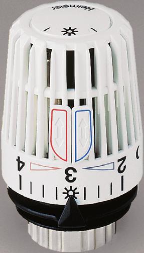
5 General notes Setting the temperature Recommended room temperatures The following temperature settings are recommended for the corresponding rooms, with cost-efficient heating in mind: Setting positions for e. g. Thermostatic heads K, VK and WK: Setting Room temperature Recommended for Position approx C (82 F) Swimming pool * C (75 F) 22 C (72 F) 20 C (68 F) 18 C (64 F) 16 C (61 F) 14 C (57 F) 12 C (54 F) Bathroom Office and children s room Lounge and dining room (basic setting) Kitchen, corridor Hobby room, bedroom All rooms at night (night time set-back) Stairway, vestibule 6 C** (43 F) Basement/cellar rooms (frost protection setting) INFO 6 C 14 C 20 C 4 C * Special thermostatic heads are available (15 C to 35 C) (59 F to 95 F) setting range) if higher temperatures are required for the swimming pool area. ** For thermostatic heads with an additional zero position, the lowest setting is 0 C (32 F). Setting the temperature The desired room temperature can be set by turning the thermostatic head (right = cooler, left = warmer). The arrow must be pointing to the appropriate setting position (number, bar, symbol). All HEIMEIER thermostatic heads are set in a climatic chamber, free of external influences such as heat build-up, sunshine, etc. Therefore the number 3 corresponds to a temperature of approx. 20 C (68 F). The difference between the numbers isapprox. 4 C (7 F) (Thermostatic head B approx. 3 C (5 F)), from bar to bar approx. 1 C (2 F). We recommend a setting at number 3, which corresponds to the basic setting of approx. 20 C (68 F) room temperature. Settings above number 4 should be avoided if a lower setting provides sufficient comfort, since an increase of 1 C (2 F) in the room temperature requires approx. 6 % more energy. The thermostatic head model K is also available with a staggered/restricted setting range (art. no ). The lower setting value at number 1 corresponds to a temperature of approx. 6 C (43 F) and acts as a frost protection setting. The temperature difference to number 2 is approx. 2 C (4 F), and to the next number up, approx. 4 C (7 F). Number 3 therefore corresponds to a temperature of approx. 12 C (54 F). The highest setting value is configured in 1 C (2 F) steps between 15 C and 25 C (59 F 77 F). This is achieved by turning the thermostatic head to the left until it stops. 5
6 General notes Setting the temperature 3 Front side setting aid For thermostatic heads K, VK, WK and F the front side of the thermostatic head acts as a setting aid if the circular script is difficult to read, or can be used as a setting guide from a greater distance. The setting at the number to the left or right of corresponds to a roomtemperature of 16 C (61 F) or 24 C (75 F). Front side setting aid INFO 6 C 14 C 20 C 4 C Brief information The most important settings are shown in abbreviated form as INFO on the thermostatic heads K, VK, WK and F Setting key two tactile markings from notch to notch approx. 1 C (2 F) Setting aid for persons with a visual impairment The thermostatic heads K, VK and WK have a setting aid for persons with a visual impairment. If the thermostatic head is turned in such a way that the tactile markings are opposite the setting arrow, a temperature of approx. 20 C (68 F) has been set. Any temperature can be set starting at this basic setting and Temperature setting, thermostatic head B Lever out the closing plug with a small screwdriver (fig. 1). The desired roomtemperature can be set with the setting key (art no ) or the universal key*) (art. no ) in a range of 8 C to 26 C (46 F to 79 F) (fig. 2). The number corresponding to the setting value can be read in the window. Number 3 corresponds to a temperature of approx. 20 C (68 F). The difference in temperature between the numbers is approx. 3 C (5 F). Push the closing plugs back until they click into place. feeling and counting the notches and turning the thermostatic head to the desired setting position at which the notch is opposite the setting arrow. The distance from notch to notch on the thermostatic head is approx. 1 C (2 F). V-exakt F-exakt hahn Luft- Universal key*) *) Alternative to setting key article no for adjusting thermostatic head B. Also for V-exakt/F-exakt thermostatic valve body, Regulux lockshield, Vekolux double connection fitting and radiator air vent. 6
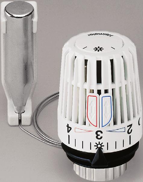
7 Installation Thermostatic heads K, DX and D, remote sensor Thermostatic valves should be installed in such a way that they control the room temperature, and that the room air is able to circulate around them unhindered. This will not be the case if thermostatic heads with integrated sensors are covered by curtains, radiator covers etc., if they are installed vertically or in narrow corners, or if they are affected by cold air, e. g. draughts. In these cases, it is necessary to install a thermostatic head with a remote sensor (or a remote dial). Protection cap Installation of thermostatic heads K, DX and D Remove the protection cap from the thermostatic valve body. Before installing, check that the thermostatic head is turned to number 5. Position the thermostatic head onto the thermostatic body, screw on and tighten with a rubber jawed wrench (approx. 20 Nm). Ensure that the setting arrow is pointing upwards. Then set the thermostatic head to number 3. Capillary tube coil Installation of remote sensor When installing the remote sensor, ensure that it is not covered by covers, curtains etc., and that it is not affected by direct sunlight or cold air. First fit the connecting part with fastening devices (dowel, screws). Then place the remote sensor in the bracket and use this to press it into the connecting part until it clicks into place. Then lay the capillary tube. Roll up any capillary tube which is not needed to the attached capillary tube coil and cover with the protection cap (see fig.). Protective cover 7
8 Installation Thermostatic head K with theft protection The HEIMEIER thermostatic heads K with theft protection are used for individualroom temperature control in public buildings, schools etc.which are used by a large number of members of the public. Two different systems are available: Theft protection from two screws (can be re-used) and theft protection from a security ring (can only be reused after the locking ring, which should be destroyed, has been replaced). Screwdriver Collar Theft protection with a security ring Remove the protection cap from the thermostatic valve body. Before installing, check that the thermostatic head is turned to number 5. Position the thermostatic head onto the thermostatic body, screw on and tighten with a rubber jawed wrench. Ensure that the setting arrow is pointing upwards. Then set the thermostatic head to number 3. When installation has been completed, remove the collar from the security ring in the direction of the arrow with a screw driver (fig. 1). The security ring can now be turned in any direction without the locking ring under the security ring coming loose. It is only possible to dismantle the thermostatic head after the theft protection (locking ring with security ring) has been destroyed with water pump pliers or a pipe wrench. The destroyed theft protection should then be carefully levered off the lower part of the head and replaced with a new theft protection (art. no ), which is simply pressed onto the lower part of the head. The thermostatic head should then be fully functional and can be re-installed. Safety screw on the locking ring Theft protection from two screws Remove the protection cap from the thermostatic valve body. Before installing, check that the thermostatic head is turned to number 5. Position the thermostatic head onto the thermostatic body, screw on and tighten with a rubber jawed wrench. Ensure that the setting arrow is pointing upwards. To ensure against theft, tighten the safety screws (fig. 2) with a hexagonal socket head wrench SW 2. Then set the thermostatic head to number 3. It is only possible to dismantle the thermostatic head after the safety screws have been loosened with the hexagonal socket head wrench SW 2. 8
9 Installation Thermostatic head WK Head body Head top part The HEIMEIER thermostatic head WK is designed to be installed onto radiators with integrated valves which have a thermostatic insert with a connector thread M 30 x 1.5. The thermostatic head can be adjusted to be installed on the left or right hand side of the radiator. Setting arrow Installation on the right hand side of the radiator Remove the securing pins on the setting arrow (fig. 1). Press in the setting arrow until it clicks into place (fig. 2). Turn the thermostatic head to number 5, place it horizontally onto the thermostatic insert, screw it on and tighten with a rubber jawed wrench (max. 15 Nm). Counter hold if necessary. Fig. 3 Fig. 4 Installation on the left hand side of the radiator Turn the thermostatic head to number 5, pull out the setting arrow and remove both securing pins (fig. 3). Turn the head body by 180 until it stops (fig. 4). Set the setting arrow to number 5 and press it on until it clicks into place (fig. 5). Place the thermostatic head horizontally onto the thermostatic insert of the radiator, screw on and tighten with a rubber jawed wrench (max. 15 Nm). Counter hold if necessary. Fig. 5 Note By pressing in and clicking the setting arrow into place, the installationposition (left/right) is set and secured. It is then no longer possible to change this position. Check that the seat is secure before installing the thermostatic insert (starting torque approx. 35 Nm). It is not permitted to use adaptors for installation onto thermostatic inserts which do not have an M 30 x 1.5 connector thread. 9
10 Installation Thermostatic head VK locking ring setting arrow 3 The HEIMEIER thermostatic head VK is designed for installation on radiators with integrated valves with a thermostatic insert for a clamping joint. Installation is carried out directly, i.e. without an adaptor. The thermostatic head VK can be installed in several positions, which each have an angle difference of 90 between them: For example, with the setting arrow pointing upwards or towards the front. Abb. 1 Installation Before mounting check that the thermostatic head is set to number 5 and that the locking ring is screwed right back. Position the thermostatic head with the setting arrow on the valve insert, e.g. to the top or to the front, and push until it audibly clicks into place (). Tighten up the locking ring firmly (approx. 10 Nm). In doing so see that the thermostatic head is set in place to the limit stop, push further if necessary (). Abb. 2 10
11 Installation Thermostatic head VD The HEIMEIER thermostatic head VD combines perfect technology with a new design. It has been specially designed for installation on radiators with integrated valves with M 30 x 1.5 connecting threads on the thermostatic insert. Its new type of construction blends harmoniously with the radiator, creating a single integrated unit. Connection cover Fig. 3 Installation Unscrew the protection cap from the thermostatic insert. Before installing, check that the thermostatic head is turned to number 5. Position the thermostatic head onto the thermostatic insert and screw on. Ensure that the setting arrow is pointing upwards (fig. 1). Firmly tighten the locking ring with a rubber jawed wrench (approx. 15 Nm). Position the connection cover (fig. 2). Position the fastening screw in front of the thread of the cover bracket. Adjust the cover and screw into place with a screwdriver (fig. 3). Then tighten the fasteningscrew by approx. 1/ 2 turns. Insert the cap so that it is aligned with the surface (fig. 4). Set the thermostatic head to number 3. Depending on the particular construction, the width of the side trim needs to be taken into account for type 11 radiators. Technical changes made by the radiator manufacturer should also be taken into account. Fig. 4 11
12 Installation Thermostatic head B The HEIMEIER thermostatic head B is used for individual room temperature control in public buildings, schools etc. which are used by a large number of members of the public. The protection cap of this theft protected thermostatic head can be turned continuously, and the set setting value cannot be changed to lower or higher temperatures without a special tool. Fig. 3 Hexagonal key SW 2 Bore hole Setting key Marking notches Closingplugs V-exakt F-exakt hahn Luft- Universal key*) Installation Remove the protection cap from the thermostatic valve body. Leverout the closing plugs with a small screwdriver (fig. 1). Open the thermostatic head through opening which is now available with settingkey art. no ) or the universal key*) art. no by turning to the left until it stops (fig. 2). Screw on the thermostatic head by turning to the right on the valve body. Continue to turn the hand wheel cap beyond the point where resistance is felt until the bore hole at the side is aligned with one of the two marking notches on the fasteningnut. The location of the lokking screws in the fastening nut is identical to the marking notches (fig. 3). Tighten the thermostatic head by inserting the hexagonal socket head wrench SW 2 Art.no (fig. 4). Tighten the safety screw in the fastening nut with the hexagonal key SW 2 until it stops. The hand wheel cap can now be turned in any direction without changing the set setting value (fig. 5). To read the setting value more clearly, turn the hand wheel cap so that the window points upwards (fig. 6). *) As an alternative to the setting key art. no for adjusting thermostatic head B. Also for the V-exakt/ F-exakt thermostatic valve body, Regelux lockshield, Vekolux double connection fitting and radiator air vent. Fig. 4 Hexagonal key SW 2 Fig. 5 Fig. 6 Window Dismantling the thermostatic head If it is necessary to dismantle the thermostatic head, turn the handwheel until the bore hole on the side is aligned with one of the two marking notches on the fasteningnut (fig. 3). Loosen the safety screw with the hexagonal key SW 2 (art. no ) (fig. 5). Unscrew the thermostatic head by inserting the hexagonal key and turning to the left (fig. 4). 12
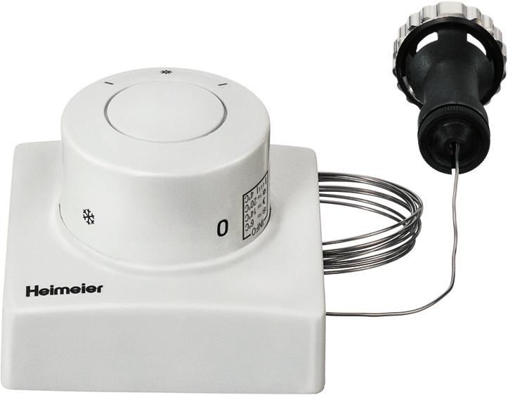
13 Installation Thermostatic head F Thermostatic valves should be installed in such a way that they control the room air temperature, and that the air is able to circulate around them unhindered. This will not be the case if thermostatic heads with integrated sensors are covered by curtains, radiator covers etc., if they are installed vertically or in narrow corners, or if they are affected by cold air, e. g. draughts. In these cases, it is necessary to install a remote dial (or a thermostatic head with a remote sensor). The remote dial should be installed in such a way that it is not covered by a cover, curtains, etc. The capillary tube can be laid onto plaster or in a Ø 23 mm conduit (fig. 1). Directional mark Slots for capillary tube Cap Cams for coiling the capillary tube Oblong holes for installation onto the flush box Base plate Screw holes for installation on the wall Installing the thermostatic head Remove the cap from the base plate (fig. 2). Install the base plate with the directional mark pointing upwards onto an even wall or a flushbox using the fixingmaterials supplied. Measure the capillary tube to be laid. Coil up the remaining capillary tube on the front side of the base plate. Warning: When installing onto an even wall, ensure that the capillary tube is run out through one of the available chases (fig. 3). Firmly press on the cap with the setting mark pointing upwards until it clicks into place (fig. 4). To install the capillary tube in a conduit, see page 14. Fig. 3 Setting mark Fig. 4 13
14 Installation Thermostatic head F Flush box Ø 60 mm Installation onto a flush box with a conduit Here, a flush box with Ø 60 mm and a conduit with Ø 23 mm should be used (fig. 1). Conduit Ø 23 mm Threaded bore holes to fixthe base plate Closing screw Thermostatic transmitter Bore hole for fastening the spiral Connecting piece Installing the capillary tube in the conduit Unscrew the closing screw (fig. 2). Remove the capillary tube with the thermostatic transmitter (fig. 3). Push the spiral through the conduit and connect to the thermostatic transmitter. Pull the transmitter and the capillary tube with the spiral through the conduit (fig. 4). Then put the individual parts back together again. Remove the protection cap from the thermostatic valve body. Turn the thermostatic head F to number 5. Position the connecting piece and tighten the locking ring with a rubber jawed wrench. Fig. 3 Spiral Fig. 4 14
15 Operation Marking, restricting or locking Thermostatic head K, VK and WK The thermostatic head is supplied ex works with two energy saving clips. The energy saving clips are initially installed to the right and left of the brief information. They can be used to mark, restrict or lock the optimal temperature setting. Brief information Marking the upper restriction of the temperature range To do this, pull back the red energy saving clip with your thumb until it stops (fig. 1), lift up and remove (fig. 2). The thermostatic head will then be set to the required temperature, e. g. number 3 20 C (68 F). Then insert the red energy saving clip into the notch on the right hand side of number 3 (fig. 3), push it Marking the lower restriction of the temperature range To do this, pull back the blue energy saving clip with your thumb until it stops (fig. 1), lift up and remove (fig. 2). The thermostatic head will then be set to the required temperature, e. g. the moon symbol 14 C (57 F). Then insert the blue energy saving clip into the notch on forward and then pull back with your thumb until it stops. the left hand side of the moon symbol (fig. 4), push it forward and then pull back with your thumb until it stops. Restricting the upper temperature range Fig. 3 3 Red energy saving clip for upper marking/ restriction e. g. 20 C (68 F) To do this, pull back the red energy saving clip with your thumb until it stops (fig. 1), lift up and remove (fig. 2). The thermostatic head will then be set to the required temperature, e. g. number 3 20 C (68 F). Then insert the red energy saving clip into the notch on the right hand side of number 3 (fig. 3) and push forward until it stops. Now, any setting up to number 3 can be made by turning the thermostatic head. It is now no longer possible to set a temperature which is above number 3. To remove the restriction, pull back the energy saving clip with your thumb until it stops. Now any temperature can be set. Restricting the lower temperature range 1 Fig. 4 2 Blue energy saving clip for lower marking/restriction e. g. 14 C (57 F) To do this, pull back the blue energy saving clip with your thumb until it stops (fig. 1), lift up and remove (fig. 2). The thermostatic head will then be set to the required temperature, e. g. the moon symbol 14 C (57 F). Then insert the blue energy saving clip into the notch on the left hand side of the moon symbol (fig. 4) and push forward until it stops. Now, any setting up to the moon symbol can be made by turning the thermostatic head. It is now no longer possible to set a temperature which is below the moon symbol. To remove the restriction, pull back the energy saving clip with your thumb until it stops. Now any temperature can be set. Locking a setting Fig. 5 3 Locking, e. g. 20 C (68 F) To lock a setting, pull back both energy saving clips with your thumb (fig. 1), lift up and remove (fig. 2). The thermostatic head will then be set to the required temperature, e. g. number 3 20 C (68 F). Then insert the red energy saving clip into the notch on the right hand side of number 3 (fig. 5) and push foward until it stops. Then insert the blue energy saving clip in the notch on the left hand side of number 3 (fig. 5) and push foward until it stops. Now the thermostatic head can no longer be adjusted. To release the lock, pull back the red of blue energy clip, or if necessary, both energy clips, until they stop. Now it is again possible to make any setting. 15
16 Operation Marking, restricting or locking Thermostatic head VD The thermostatic head is supplied ex works with two energy saving clips. The energy saving clips are initially installed next to numbers 0 and 5. They can be used to mark, restrict or lock the optimal temperature setting. Marking the upper restriction of the temperature range To do this, pull back the red energy saving clip until a slight resistance is felt, then lift up and remove. The thermostatic head will then be set to the required temperature, e. g. number 3 20 C (68 F). Then insert the red energy saving clip into the notch on the right hand side of number 3 (fig. 1), push forward and then pull back until a slight resistance is felt. 3 Marking the lower temperature range To do this, pull back the blue energy saving clip until a slight resistance is felt, lift up and remove. The thermostatic head will then be set to the required temperature, e. g. the moon symbol 14 C (57 F). Then insert the blue energy saving clip in the notch on the left hand side of the moon symbol (fig. 2), push forward and then pull back until a slight resistance is felt. Restricting the upper temperature range To do this, pull back the red energy saving clip until a slight resistance is felt, lift up and remove. The thermostatic head will then be set to the required temperature, e. g. number 3 20 C (68 F). Then insert the red energy saving clip into the notch on the right hand side of number 3 (fig. 1) and push forward until it stops. Now any setting up to number 3 can be set by turning the thermostatic head. It is now no longer possible to set a temperature which is above number 3. To remove the restriction, pull back the energy clip until a slight resistance is felt. Now any temperature can be set. 1 2 Restricting the lower temperature range To do this, pull back the blue energy saving clip until a slight resistance is felt, lift up and remove. The thermostatic head will then be set to the required temperature, e. g. the moon symbol 14 C (57 F). Then insert the blue energy saving clip in the notch on the left hand side of the moon symbol (fig. 2) and push forward until it stops. Now, any setting up to the moon symbol can be made by turning the thermostatic head. Settings which are below the moon symbol are now no longer possible. To remove the restriction, pull back the energy clip until a slight resistance is felt. Now any temperature can be set. Locking a setting Fig. 3 3 To lock a setting, pull back both energy saving clips until a slight resistance is felt, lift up and remove. The thermostatic head will then be set to the required temperature, e. g. number 3 20 C (68 F). Then insert the red energy saving clip into the notch on the right hand side of number 3 (fig. 3) and push forward until it stops. The insert the blue energy saving clip in the notch on the left hand side of number 3 and push forward until it stops. Now the thermostatic head can no longer be adjusted. To remove the lock, pull back the red or the blue energy saving clip, or if necessary, both energy saving clips, until a slight resistance is felt. Now it is again possible to make any setting. Hidden restriction or locking of a setting With the stop pins which can be removed from the inside of the connection cover, a hidden limitation or locking, as already described, can be carried out. Ensure that the stop pins click into place in the required notch when they are pushed forward until they stop. It is then no longer possible to pull back the stop pins. 16
17 Operation Hidden restriction or locking Thermostatic heads K and VK 1. Stop clip Removal device Head body Graduation cap Stop clips The thermostatic head is supplied ex works with two stop clips. These are initially installed on the right hand side of number 5 and on the left hand side of the frost protection setting. Restricting the upper temperature range Set thermostatic head to number 5. Insert the removal device (art. no ) above the adjusting arrow between the graduation cap and the head body. Rotate the graduation cap clockwise beyond a perceptible resistance. Before withdrawing the graduation cap set the thermostatic head to the required temperature, e.g. number 3 20 C. Withdraw graduation cap (fig. 1). Slide up the stop clip from the right hand position next to number 5 with the removal device and extract it (fig. 2). They can be used to make a hidden restriction, or lock the optimal temperature setting. First remove the energy saving clips (see page 15). Afterwards slide the stop clip onto the 2 nd web on the right next to number 3 until it clicks into place (fig. 3). Put on the graduation cap again so that the number 3 lines up with the adjusting arrow. Press the graduation cap down firmly until it clicks into place (fig. 4). Now all settings up to number 3 can be made by turning the thermostatic head. Settings above number 3 are no longer possible. Fig. 3 Adjusting arrow 3 Fig Fig. 5 Stop clip 4. Graduation cap 5 Removal device Head body Stop clips Fig. 6 Restricting the lower temperature range Set thermostatic head to number 5. Insert the removal device (art. no ) above the adjusting arrow between the graduation cap and the head body. Rotate the graduation cap clockwise beyond a perceptible resistance. Before withdrawing the graduation cap set the thermostatic head to the required temperature, e.g. moon symbol 14 C. Withdraw graduation cap (fig. 1). Slide up the stop clip from the left hand position next to the frost protection position with the removal device and extract it (fig. 6). Afterwards slide the stop clip onto the 2 nd web on the left next to the moon symbol until it clicks into place (fig. 7). Put on the graduation cap again so that the moon symbol lines up with the adjusting arrow. Press the graduation cap down firmly until it clicks into place (fig. 8). Now all settings up to the moon symbol can be made by turning the thermostatic head. Settings below the moon symbol are no longer possible. Fig Adjusting arrow Combined upper and lower restriction of the temperature range It is possible to combine the upper and lower restriction in one operation. To do this, the thermostatic head should be set at the required upper or lower temperature before the cap with graduation is removed. When the restriction has been set, position the cap with graduation at the same setting. Fig. 8 To reset the basic position if the regulating head has been adjusted, see page
18 Operation Hidden restriction or locking Thermostatic heads K and VK Graduation cap Stop clips 5 Removal device Head body Locking a setting Set thermostatic head to number 5. Insert the removal device (art. no ) above the adjusting arrow between the graduation cap and the head body. Rotate the graduation cap clockwise beyond a perceptible resistance. Before withdrawing the graduation cap set the thermostatic head to the required temperature, e.g. number 3 20 C. Withdraw graduation cap (fig. 1). Slide up the stop clips from the right hand position next to number 5 and from the left hand position next to the frost protection position with the removal device and extract them (fig. 2). Afterwards slide one stop clip onto the 2 nd web on the left next to number 3 and the other one on the 2 nd web on the right next to number 3 until they click in place. Put on the graduation cap again so that the number 3 lines up with the adjusting arrow. Press the graduation cap down firmly until it clicks into place (fig. 4). The thermostatic head can no longer be adjusted. Stop clips Fig. 3 Adjusting arrow 3 Fig. 4 Releasing a hidden restriction or lock To do this, remove the stop clips from the current restriction or locking positions and insert them into their original positions on the 2 nd web on the right hand side of number 5 and the 2 nd web on the left hand side of the frost protection setting. To reset the basic position if the regulating head has been adjusted, see page
19 Operation Hidden restriction or locking Thermostatic head F The thermostatic head F is supplied from the factory with two stop clips. These are within the cap fitted initially on the right next to number 5 and on the left next to number 0. They can be used for hidden limitation or locking of the optimal temperature setting. Number 3 Cap Number 2 Cap Upper limitation of the temperature range Set the thermostatic head to the required temperature, e.g. number 3 20 C (68 F) (). Lift up the cap from the base plate with a screwdriver (Fig. 3). Remove the stop clip from the position on the right hand side of number 5 and then push it on the 1st web on the right hand side of number 3 (Fig. 5). Firmly press up the cap with setting mark pointing upwards onto the base plate until it clicks in (Fig. 8). Settings up to number 3 are now possible by turning the thermostatic head. Settings above number 3 are no longer possible. Fig. 3 Fig. 4 Stop clips Base plate Fig. 5 Lower limitation of the temperature range Set the thermostatic head to the required temperature, e.g. number 2 16 C (61 F) (). Lift up the cap from the base plate with a screwdriver (Fig. 4). Remove the stop clip from the position on the left hand side of number 0 and then push it on the 1st web on the left hand side of number 2 (Fig. 6). Firmly press up the cap with setting mark pointing upwards onto the base plate until it clicks in (Fig. 9). Settings down to number 2 are now possible by turning the thermostatic head. Settings under number 2 are no longer possible. Stop clips Base plate Fig. 6 Combined upper and lower limitation of the temperature range It is possible to combine the upper and lower limitation in one operation. While doing so the thermostatic head should be set to the required temperature before removing the cap. Stop clips Base plate Locking a setting Setting mark Fig. 7 Setting mark Set the thermostatic head to the required setting, e.g. number 3 20 C (68 F) (). Lift up the cap from the base plate with a screwdriver (Fig. 3). other on the 1st web on the right hand side of number 3 (Fig. 7). Firmly press up the cap with setting mark onto the base plate until it clicks in (Fig. 8). Fig. 8 Fig. 9 Remove the stop clips from the positions on the right hand side of number 5 and on the left hand side of number 0. Then push one stop clip on the 1st web on the left hand side of number 3 and the The thermostatic head can no longer be adjusted. 19
20 Operation Basic setting Thermostatic heads K and VK Adjusting arrow Adjustment notch 4. Graduation cap Removal device Head body If the graduation cap is to be adjusted after dismounting, or if the graduation cap has been put on wrongly, the thermostatic head must be reset to the basic position. If necessary, release restricting or locking with the economy clips (see page 15). Set thermostatic head to number 5. Insert the removal device (art. no ) above the adjusting arrow between the graduation cap and the head body. Rotate the graduation cap clockwise beyond a perceptible resistance (fig. 1). If necessary, release hidden restricting or locking (see page 18). Afterwards screw the complete regulating head out anticlockwise. Put the regulating head on to the head body so that the adjustment notch and adjusting arrow are opposite one another (fig. 2) and afterwards lightly screw in clockwise until it stops. Turn back the regulating head anticlockwise until the adjustment notch points to the arrow marking on the head body (fig. 3). Put on the graduation cap again so that the number 3 lines up with the adjusting arrow. Press graduation cap down firmly until it clicks into place (fig. 4). Regulating head Arrow marking Adjustment notch Fig. 3 Graduation cap 3 Fig. 4 20
21 Operation Precision presetting or finest presetting V-exakt/F-exakt thermostatic valve body To guarantee even hot water distribution and warming of the radiators, a hydraulic balance within the heating system is necessary. HEIMEIER offers several possibilities, e. g.: 1. V-exakt thermostatic valve bodies with precision presetting 2. F-exakt thermostatic valve bodies with finest presetting 3. Regulux lockshield 4. Balancing valves Directional marking Setting key Index Operation of the presetting or finest presetting The precision presetting/finest presetting of the V-exakt/F-exakt thermostatic valve bodies can be selected from 1; 2; 3; 4; 5 and 6. Setting 6 corresponds to the normal setting (manufacturer s setting). There is a flow range hidden behind every setting value, which has a gap-free connection to the next range. It is therefore not necessary, and not permitted, to make intermediary settings. With the key, only a specialist can create or change the setting. It is not possible for an unqualified person to tamper with the settings without a tool. Position the setting key onto the valve insert and turn until it clicks into place. Turn the index of the required setting value to the directional marking of the valve body. Remove the key. The setting can be read on the valve insert from the adjustment direction. Setting key for precision presetting and finest presetting Art. no V-exakt F-exakt hahn Luft- Index Universal key as an alternative to the setting key for adjusting V-exakt/F-exakt. Also for thermostatic head B (temperature setting), thermostatic head K (for pushing out the stop clips), Regulux lockshield, Vekolux double connection fitting and radiator air vent. Art. no
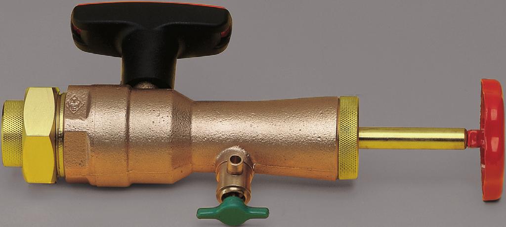
22 Retrofitting instructions Thermostatic valve bodies with boss marking Boss marking Numerical cap Brass Nickel-plated brass V-exakt F-exakt Thermostatic inserts Since 1994, the body of the Standard, V-exakt and F-exakt valve bodies and the Mikrotherm manual radiator valves in nominal widths NW 10 and NW 15 have been manufactured to the same design. All valve bodies have the same seat diameter. An external indication that the design is the same is the notch which has been cast onto one side of the body (fig. 1). All valve bodies which have this mark can be retrofitted. By replacing the inserts, e. g. the Standard thermostatic valve bodies can be retrofitted in V-exakt or F-exakt thermostatic valve bodies with precision presetting or finest presetting. It is necessary to make this replacement e. g. when the demands made on the valve bodies change due to subsequent changes to the existing heating system, e. g. when a connection to a district heating network is established. The individual thermostatic inserts can be identified by their different numerical caps (V-exakt: brass; F-exakt: brass nickel-plated) (fig. 2). Fitting tool Art. no Fig. 3 Installation The replacement insert can be fitted quickly and cheaply with the fitting tool, without draining off the heating system (fig. 3). For information about this, see page 24. The thermostatic valve insert should always only be loosened or tightened with a special key SW 19 (fig. 4) (starting torque 35 Nm). Box spanner Art. no Fig. 4 22
23 3 Retrofitting instructions Mikrotherm manual radiator valve Fig. 3 T-label Connector thread Boss marking All HEIMEIER Mikrotherm manual radiator valves with a T label and with a connecting thread for the thermostatic head on the body (fig. 1) can be converted to a thermostatic valve. Manual valves with a connecting thread for the thermostatic head on the body from the 1988 series onwards, as well as those with boss markings on the body Installation Open the manual valve, and drain off the risers and the system. Unscrew the fastening screw and remove the hand wheel cap. Loosen the insert with an open-jawed spanner SW 20 and unscrew (fig. 2). Clean all traces of dirt deposits and grit from the valve seat. Do not clean with a hard or abrasive object (fig. 3). Screw in the thermostatic insert (fig. 4). Tighten with a box spanner SW 19 (fig. 5). Box spanner art. no Install the thermostatic head (K, D, F, B) (fig. 6). from the April 1994 series onwards can also be converted to a thermostatic valve with a fitting device without draining the system. For this, please ask for separate operating instructions. Fig. 4 Fig. 5 Fig. 6 23
24 Retrofitting instructions Fitting tool Ball valve Hand wheel Spindle 1 Valve connection piece Drain tap Fitting tool for replacing thermostatic inserts (replacement inserts) from the end of 1982 series onwards (connection thread for thermostatic heads on the body), as well as replacement inserts with presetting from the new series at the start of 1985 onwards. 1. Unscrew the thermostatic head from the thermostatic valve body. 2. Lightly loosen the thermostatic insert (kvs replacement) with a box spanner SW Screw the fitting tool onto the thermostatic valve body. 4. For narrow radiator niches and covers, first screw the valve connection piece with the thermostatic valve body into place. 5. Screw the valve connection piece into place with the fitting tool. 6. Close the drain tap. Open the ball valve and push in the spindle of the fitting tool until it clicks into the thermostatic insert. 7. Turn the hand wheel on the fitting tool to the left until the thermostatic insert has been loosened from the body and slowly pull it back until it stops. 8. Close the ball valve. 9. Open the drain tap and catch any water which runs out. 10. Open the screw of the fitting tool below the hand wheel. 11. Remove the dismantled thermostatic insert from the fitting tool and replace with a new one. Install the new thermostatic insert by following the above procedure in reverse. When the new thermostatic insert has been installed, drain off the fitting tool. Then unscrew the fitting tool from the thermostatic valve body and tighten the insert with the box spanner SW 19. Screw on the thermostatic head. Brochure 1.8 Printed on chlorine-free bleached paper / We reserve the right to make technical modifications. Theodor Heimeier Metallwerk GmbH Postfach 1124, Erwitte, Germany Phone Fax
Regulux. Radiator lockshield with drain-off facility. To be precise.
 Radiator lockshield with drain-off facility To be precise. Description Assembly Regulux Closing cap Thrust piece HEIMEIER radiator lockshield for shutting off, presetting, draining off and filling. Separate
Mikrotherm. Manual Radiator Valves With presetting
 Mikrotherm Manual Radiator Valves With presetting IMI HEIMEIER / Thermostatic Heads & Radiator Valves / Mikrotherm Mikrotherm The Mikrotherm manual radiator valve is used in warm water pump heating systems,
Thermostatic heads. for all thermostatic valve bodies and radiators with integrated valves. To be precise.
 Thermostatic heads for all thermostatic valve bodies and radiators with integrated valves To be precise. Thermostatic heads Table of contents Page Thermostatic heads Construction Application 4 Function
Control valves for floor heating systems. Floor Heating Manifolds
 Control valves for floor heating systems Floor Heating Manifolds IMI HEIMEIER / Floor Heating Control / Control valves for floor heating systems Control valves for floor heating systems Supply control
Thermostatic valve bodies
 Thermostatic valve bodies for all thermostatic heads and actuators Pressurisation & Water Quality Balancing & Control Thermostatic Control ENGINEERING ADVANTAGE ThermosTaTic valve bodies Table of contents
regulux Radiator lockshield with drain-off facility Pressurisation & Water Quality Balancing & control thermostatic control engineering ADVANTAge
 regulux Radiator lockshield with drain-off facility Pressurisation & Water Quality Balancing & control thermostatic control engineering ADVANTAge Regulux Description Separate presetting cone for consistent
Thermostatic head K. Thermostatic heads with built-in sensor and remote sensor
 Thermostatic head K Thermostatic heads with built-in sensor and remote sensor IMI HEIMEIER / Thermostatic Heads & Radiator Valves / Thermostatic head K Thermostatic head K The thermostatic heads K are
Thermostatic heads. For all thermostatic valve bodies and radiators with integrated valves
 Thermostatic heads For all thermostatic valve bodies and radiators with integrated valves Pressurisation & Water Quality Balancing & Control Thermostatic Control ENGINEERING ADVANTAGE ThermostatIC HEADS
Regulux. Return Lockshield Radiator lockshield with consistent presetting and drain-off facility
 Regulux Return Lockshield Radiator lockshield with consistent presetting and drain-off facility IMI HEIMEIER / Thermostatic Heads & Radiator Valves / Regulux Regulux The Regulux is used in warm water pump
Thermostatic valves with radiator connection systems
 Multilux Eclipse Thermostatic valves with radiator connection systems with two-point connection for two-pipe heating systems, with automatic flow limitation IMI HEIMEIER / Thermostatic heads and Radiator
Calypso exact. Thermostatic Radiator Valves With stepless precision presetting
 Calypso exact Thermostatic Radiator Valves With stepless precision presetting IMI HEIMEIER / Thermostatic Heads & Radiator Valves / Calypso exact Calypso exact Calypso exact thermostatic valve bodies are
Thermostatic heads. Thermostatic Heads For all thermostatic valve bodies and radiators with integrated valves
 Thermostatic heads Thermostatic Heads For all thermostatic valve bodies and radiators with integrated valves IMI HEIMEIER / Thermostatic Heads & Radiator Valves / Thermostatic heads Thermostatic heads
E-Z Valve. Thermostatic valves with radiator connection systems For single and two-pipe heating systems
 E-Z Valve Thermostatic valves with radiator connection systems For single and two-pipe heating systems IMI HEIMEIER / Thermostatic heads and Radiator valves / E-Z Valve E-Z Valve E-Z Valve with immersion
Design-Edition. Design-Edition Thermostatic valves and lockshields, sets
 Design-Edition Design-Edition Thermostatic valves and lockshields, sets IMI HEIMEIER / Design-Edition / Design-Edition Design-Edition The sets are an elegant solution for e. g. design radiators. A sublime
TRV pack Eclipse. Thermostatic valves with radiator connection systems Thermostatic raditor valve with automatic flow control, head and lockshield
 TRV pack Eclipse Thermostatic valves with radiator connection systems Thermostatic raditor valve with automatic flow control, head and lockshield IMI HEIMEIER / Thermostatic heads and Radiator valves /
Thermostatic three-way valve body. Thermostatic Radiator Valves without presetting, with automatic bypass control
 Thermostatic three-way valve body Thermostatic Radiator Valves without presetting, with automatic bypass control IMI HEIMEIER / Thermostatic Heads & Radiator Valves / Thermostatic three-way valve body
Eclipse F. Thermostatic Radiator Valves Thermostatic radiator valve with automatic flow limitation
 Eclipse F Adaptative Flow Control Thermostatic Radiator Valves Thermostatic radiator valve with automatic flow limitation IMI HEIMEIER / Thermostatic Heads & Radiator Valves / Eclipse F Eclipse F The thermostatic
Multibox. Flush Individual Room Control for Floor Heating Systems. To be precise.
 Flush Individual Room Control for Floor Heating Systems To be precise. Contents Page Multibox K, Multibox RTL and Multibox K-RTL Description Construction Application 4 Temperature Setting 4 Function Article
Standard. thermostatic valve body without presetting
 Standard thermostatic valve body without presetting Pressurisation & Water Quality Balancing & Control Thermostatic Control EnGInEErInG advantage The standard thermostatic valve bodies are used in two-pipe
Multilux 4-Eclipse-Set
 Multilux -Eclipse-Set Design-Edition with two-point connection, angle and straight type, for R / and connection, with automatic flow limitation IMI HEIMEIER / Design-Edition / Multilux -Eclipse-Set Multilux
For reversed flow direction. Thermostatic Radiator Valves Thermostatic valve body with and without presetting
 For reversed flow direction Thermostatic Radiator Valves Thermostatic valve body with and without presetting IMI HEIMEIER / Thermostatic Heads & Radiator Valves / For reversed flow direction For reversed
Radiator Connection System, Thermostatic Valve and Return Valve with Shutoff Function
 HERZ-3000 Radiator Connection System, Thermostatic Valve and Return Valve with Shutoff Function Standard Sheet for 3791 3792 Edition 1000 (0999) Dimensions in mm 1 3001 01 Cone sleeve 1 3002 01 Connection
thermostatic valve body with stepless precision presetting
 Thermostatic Radiator Valves V-exact II thermostatic valve body with stepless precision presetting Pressurisation & Water Quality Balancing & Control Thermostatic Control ENGINEERING AVANTAGE V-exact II
Thermostatic valve bodies
 Thermostatic valve bodies for single pipe heating systems Thermostatic valves with radiator connection systems IMI HEIMEIER / Thermostatic heads and Radiator valves / Thermostatic valve bodies for single
Eclipse. Thermostatic Radiator Valves Thermostatic radiator valve with automatic flow limitation
 Eclipse Adaptative Flow Control Thermostatic Radiator Valves Thermostatic radiator valve with automatic flow limitation IMI HEIMEIER / Thermostatic Heads & Radiator Valves / Eclipse Eclipse The thermostatic
IMI Heimeier Kit Hydroca ble
 IMI Heimeier Kit Hydroca ble Thermostatic valves with radiator connection systems Thermostatic valve and lockshield with tube-bend for the installation as angle form or axial form with press- or sliding
Standard. Thermostatic Radiator Valves Thermostatic valve body without presetting
 Standard Thermostatic Radiator Valves Thermostatic valve body without presetting IMI HEIMEIER / Thermostatic Heads & Radiator Valves / Standard Standard The Standard thermostatic valve bodies are used
Calypso TRV-3. (for the Nordic countries) Thermostatic radiator valves With presetting
 Thermostatic radiator valves With presetting") Calypso TRV-3 (for the Nordic countries) Thermostatic radiator valves With presetting IMI TA / Thermostatic heads and Radiator valves / Calypso TRV-3 (for the Nordic countries) Calypso TRV-3 (for the Nordic
Calypso TRV-3 (for the Nordic countries) Thermostatic radiator valves With presetting IMI TA / Thermostatic heads and Radiator valves / Calypso TRV-3 (for the Nordic countries) Calypso TRV-3 (for the Nordic
Flush individual room control for floor heating systems
 Multibox Flush individual room control for floor heating systems Pressurisation & Water Quality Balancing & Control Thermostatic Control ENGiNEERiNG ADVANTAGE Multibox is used for decentralized control
Multibox. Floor Heating Controller Flush individual room control for floor heating systems
 Multibox Floor Heating Controller Flush individual room control for floor heating systems IMI HEIMEIER / Floor Heating Control / Multibox Multibox K, RTL and K-RTL Multibox K, RTL and K-RTL is used for
V-exact II. Thermostatic Radiator Valves Thermostatic valve body with stepless precision presetting
 V-exact II Thermostatic Radiator Valves Thermostatic valve body with stepless precision presetting IMI HEIMEIER / Thermostatic Heads & Radiator Valves / V-exact II V-exact II V-exact II thermostatic valve
Standard. Thermostatic Radiator Valves Thermostatic valve body without presetting
 Standard Thermostatic Radiator Valves Thermostatic valve body without presetting IMI HEIMEIER / Thermostatic Heads & Radiator Valves / Standard Standard The Standard thermostatic valve bodies are used
Halo. Thermostatic heads with built-in sensor
 Halo Thermostatic heads with built-in sensor IMI HEIMEIER / Thermostatic Heads & Radiator Valves / Halo Halo The thermostatic head Halo is used to control the temperature of individual rooms using, for
Standard. Thermostatic Radiator Valves Thermostatic valve body without presetting
 Standard Thermostatic Radiator Valves Thermostatic valve body without presetting IMI HEIMEIER / Thermostatic Heads & Radiator Valves / Standard Standard The Standard thermostatic valve bodies are used
Thermostatic head B. Thermostatic heads Secured model designed for public buildings
 Thermostatic head B Thermostatic heads Secured model designed for public buildings IMI HEIMEIER / Thermostatic Heads & Radiator Valves / Thermostatic head B Thermostatic head B The thermostatic head B
Floor Control Set. Floor Heating Controller For constant control of the supply temperature
 Floor Control Set Floor Heating Controller For constant control of the supply temperature IMI HEIMEIER / Floor Heating Control / Floor Control Set Floor Control Set The Floor Control Set with return addition
Multibox 4. Floor Heating Controller Flush individual room control for floor heating systems with supply shut-off
 Multibox 4 Floor Heating Controller Flush individual room control for floor heating systems with supply shut-off IMI HEIMEIER / Floor Heating Control / Multibox 4 Multibox 4 RTL and K-RTL and K-RTL is
Three-way reversing valve
 Three-way reversing valve For heating and cooling systems Pressurisation & Water Quality Balancing & Control thermostatic Control engineering avantage Three-way reversing valve for the distribution of
HERZ-DR-T-90. Radiator Control Valves with Pre-Setting Function by Means of Double Cone, Suitable for Conversion to Thermostatic Operation. H max.
 Radiator Control Valves with Pre-Setting Function by Means of Double Cone, Suitable for Conversion to Thermostatic Operation Standard Sheet for 6823/ 6824 Edition 1000 (0999) 6823 6824 Special Models 1
Standard C. Thermostatic Radiator Valve Thermostatic valve body with reversed direction of operation
 Standard C Thermostatic Radiator Valve Thermostatic valve body with reversed direction of operation IMI HEIMEIER / Thermostatic Heads & Radiator Valves / Standard C Standard C The Standard C thermostatic
Vekotrim. Valves for radiators with integrated valve Double connection fitting with shut-off ball valves for radiators with integrated valves
 Vekotrim Valves for radiators with integrated valve Double connection fitting with shutoff ball valves for radiators with IMI HEIMEIER / Thermostatic Heads & Radiator Valves / Vekotrim Vekotrim The Vekotrim
Dynalux. Floor Heating Manifolds Underfl oor heating circuit manifold
 Dynalux Floor Heating Manifolds Underfl oor heating circuit manifold IMI HEIMEIER / Floor Heating Control / Dynalux Dynalux Dynalux adjusts the flow rate in the individual heating circuits directly in
CALIS-TS-3-D. HERZ Armaturen. Standard Sheet for 7745, 7746, 7761 Edition 0700 (0999) Three-Way Valves in 3-D Design for One-Pipe Systems
 Three-Way Valves in 3-D Design for One-Pipe Systems") -3-D Three-Way Valves in 3-D Design for One-Pipe Systems Standard Sheet for 7745, 7746, 7761 Edition 0700 (0999) Dimensions in mm 7761 C H -E 7745 7746 C H H = Height HEZ-thermostat 37,5 Ø Flow-T-Piece
-3-D Three-Way Valves in 3-D Design for One-Pipe Systems Standard Sheet for 7745, 7746, 7761 Edition 0700 (0999) Dimensions in mm 7761 C H -E 7745 7746 C H H = Height HEZ-thermostat 37,5 Ø Flow-T-Piece
THERMOSTATIC EXPANSION VALVES AND THERMOSTAT CONTROL DEVICES
 FUNCTION Thermostatic expansion valves are used to regulate and cut-off the flow of the heat transfer fluid that circulates inside airconditioning system terminals (radiators, fan coils, etc.). Thermostat
THERMOSTATIC EXPANSION VALVES AND THERMOSTAT CONTROL DEVICES
 FUNCTION Thermostatic expansion valves are used to regulate and cut-off the flow of the heat transfer fluid that circulates inside airconditioning system terminals (radiators, fan coils, etc.). Thermostat
HERZ TS-3000 HERZ HERZ Armaturen A-1230 Vienna Richard-Strauss-Straße 22
 HERZ TS-3000 HERZ-3000 Connection system for radiators Thermostatic valve and shut-off return valve Standard sheet for 3691-3694 3791 3794 Issue 0702 G 3/4 Dimensions in mm 1 3002 31 Connection nipples
TS RD 7761 RD, 7761 RD
 1/2 HERZ Calis TS RD three way valve HERZ Calis TS RD 100% three-way valve for heating and cooling Datasheet for 1 7761 RD, Issue 0716 Dimensions in mm Order number Dimension R A B C kvs dp (bar) maximum
HERZ-Thermostatic and Return Valves. DE LUXE Edition 1000 (0999) HERZ Armaturen. Standard Sheet for DE LUXE. Richard-Strauss-Straße 22 A-1230 Wien
 HERZ Armaturen. Standard Sheet for DE LUXE. Richard-Strauss-Straße 22 A-1230 Wien") HERZ-Thermostatic and Return Valves Standard Sheet for DE LUXE Edition 1000 (0999) This series consists of HERZ radiator thermostats, HERZ-TS-90 thermostatic valves and HERZ return valves. These components
HERZ-Thermostatic and Return Valves Standard Sheet for DE LUXE Edition 1000 (0999) This series consists of HERZ radiator thermostats, HERZ-TS-90 thermostatic valves and HERZ return valves. These components
Installation and Operating Instructions DÜRR Regeneration Unit for X-ray developers XR 24, XR24 II, XR 24 Nova, XR 24 Pro
 Installation and Operating Instructions DÜRR Regeneration Unit for X-ray developers XR 24, XR24 II, XR 24 Nova, XR 24 Pro 2006/01 Content Important Information 1. Notes... 3 1.1 CE - Labeling... 3 1.2
INSTALLTION FOR THERMOSTATIC VALVES
 SS-TH1000 ½ THERMOSTATIC VALVE SS-TH3000 ¾ THERMOSTATIC VALVE SS-TH2000 ½ THERMOSTATIC VALVE WITH BUILT IN VOLUME CONTROL SS-TH4000 ¾ THERMOSTATIC VALVE WITH BUILT IN VOLUME CONTROL Features: Ability to
TK-5001, Pneumatic Room Thermostats General Instructions GENERAL INFORMATION INSTALLATION
 TK-5001, 5101 TAC 1354 Clifford Avenue P. O. Box 2940 Loves Park, IL 61132-2940 www.tac.com Pneumatic Room Thermostats General Instructions GENERAL INFORMATION The pneumatic thermostats are used for proportional
INSTALLATION FOR THERMOSTATIC VALVES
 SS-TH1000 1/2 Thermostatic Valve SS-TH3000 3/4 Thermostatic Valve SS-TH2000 1/2 Thermostatic Valve with built in volume control SS-TH4000 3/4 Thermostatic Valve with built in volume control Features: Ability
Chapter 3 Cooling, heating and ventilation systems
 3 1 Chapter 3 Cooling, heating and ventilation systems Contents Antifreeze mixture..............................see Chapter 1 Cooling fan assembly - testing, removal and refitting.............8 Cooling
Innovation + Quality. Product range. Awards:
 Innovation + Quality Valves, controls + systems Unibox and limitation of return temperature in surface heating systems Floorbox Installation of surface heating systems without distributor/collector Product
ONE PIECE TOILET LT3. Model: MPN: B0940 INSTALLATION INSTRUCTIONS. Version: 1.0
 Model: MPN: B0940 INSTALLATION INSTRUCTIONS Version: 1.0 READ ALL INSTRUCTIONS BEFORE UNPACKING THE PRODUCT INSTRUCTIONS THAT, IF IGNORED COULD RESULT IN DEATH OR SERIOUS INJURY CAUSED BY INCORRECT HANDLING
CEILING FAN OWNER S MANUAL
 Style that revolves around you. CEILING FAN OWNER S MANUAL Total fan weight *53 lbs. WEXFORD 11/05 WARNING: Read and follow these instructions carefully and be mindful of all warnings shown throughout.
Connection set. Radiator connection set for thermostatic and manual operation Ø 12
 Connection set Radiator connection set for thermostatic and manual operation Data sheet for 1 7650 00 Issue 0405 Control valves Connection pipe Ø 12 L L = 600 1 7650 00 L = 1000 1 7650 01 Bypass bodies
Automatic balancing valves ASV-PV (new generation) DN 32-50
 DN 32-50") Automatic balancing valves ASV-PV (new generation) DN 32-50 ASV-PV DN 32-50 Description ASV whiteboard animation SMT/SI ASV valves are automatic balancing valves. Together with Danfoss presetting radiator
Automatic balancing valves ASV-PV (new generation) DN 32-50 ASV-PV DN 32-50 Description ASV whiteboard animation SMT/SI ASV valves are automatic balancing valves. Together with Danfoss presetting radiator
MINIATURE THERMOSTATIC VALVE
 SS-TH500-1/2 Features: Ability to pre-select water temperature thus conserving water Compensates for water pressure fluctuations preventing scalding Safety button at 100 F prevents accidental scalding
Contents. 1. Instructions for safety and use 20
 Contents 1. Instructions for safety and use 20 2. Positioning in the counter top 21 2.1 Fixing to the supporting structure 21 2.2 Positioning the adhesive sponge 22 2.3 Positioning the fastening clips
INSTALLATION AND MAINTENANCE OF THE "THOMPSON-BRITISH" AUTOMATIC PLATEN
 INSTALLATION AND MAINTENANCE OF THE "THOMPSON-BRITISH" AUTOMATIC PLATEN Installation and Maintenance of The "Thompson-British" Auto Platen Lifting Bolt. Motor. Direction of rotation. Oiling. The machine
Audi-Larm Audible Alarm
 Audi-Larm Audible Alarm MAINTENANCE AND REPAIR TAL 1706 (L) Rev. 7 MSA 2017 Prnt. Spec. 10000005389(I) Mat. 10093084 Doc. 10093084 REPLACEMENT KITS AND PARTS LIST TAL 1706 (L) Rev. 7-10093084 2 Exploded
Part 2: Installation Instructions cl
 Contents Page: Part 2: Installation Instructions cl. 381-382 1. Delivery scope............................... 3 2. General and Transportation safety precautions........... 3 3. Stand installation 3.1 Installing
MK 8706 / MB 8706 CONCEALED THERMOSTATIC SHOWER VALVE INSTALLATION GUIDE
 MK 8706 / MB 8706 CONCEALED THERMOSTATIC SHOWER VALVE INSTALLATION GUIDE DIMENSIONS 150mm 55mm 200mm 67mm Hot water ¾ BSP Parallel Cold water ¾ BSP Parallel 160mm x 120mm aperture behind face plate for
CEILING FAN OWNER'S MANUAL
 Style that revolves around you. CEILING FAN OWNER'S MANUAL VANTAGE with DC motor 12/14 WARNING: Read and follow these instructions carefully and be mindful of all warnings shown throughout. GENERAL INSTALLATION
Minimalist Bottom Outlet Thermostatic Bar Shower. Telephone Product Specification
 Product Specification ~ Minimum Working Pressure 0.5 bar ~ Maximum Working Pressure 4.0 bar ~ Cold Water Supply Temp 4-20 c ~ Hot Water Supply Temp 55-85 c ~ Fixing Centres 150mm +/- 20mm ~ Outlet size
Radiator Valve Program
 Radiator Valve Program Heat seeks cold faster when the temperature difference is greater. Lowering the temperature of a room reduces the amount of heat leaving the room (heat loss). Installing thermostats
ENGINEER S MANUAL No.01
 1-NEEDLE, UNISON FEED, LOCKSTITCH MACHINE (AUTOMATIC LUBRICATION) LU-1510 1-NEEDLE, UNISON FEED, LOCKSTITCH MACHINE WITH AUTOMATIC THREAD TRIMMER (AUTOMATIC LUBRICATION) LU-1510-7 1-NEEDLE, UNISON FEED,
thermostatic inserts for radiators with integrated valves
 s for radiators with integrated valves Pressurisation & Water Quality Balancing & Control Thermostatic Control engineering advantage valves for radiator with integrated valve technical description heimeier
HD Kompakt Service Manual
 HD Kompakt Service Manual English 5.906-583.0 Rev. 00 (08/13) 1 1 Contents 1 Contents.................................................... 2 2 Preface.....................................................
Model: 1100 Float-Controlled Condensate Trap, PN 25
 1 Safety instructions Model: 1100 Float-Controlled Condensate Trap, PN 25 1.1 Proper use Any improper use, intervention in the design and deviation from the design data automatically lead to termination
Straight pattern thermostatic radiator valve vertical or horizontal mounting with (368T CPDLS) matching drain off lockshield
 matching drain off lockshield") Straight pattern thermostatic radiator valve vertical or horizontal mounting with (368T CPDLS) matching drain off lockshield Straight pattern TRV & drain off lockshield pack Size Pattern No. Pack 1 Qty
Straight pattern thermostatic radiator valve vertical or horizontal mounting with (368T CPDLS) matching drain off lockshield Straight pattern TRV & drain off lockshield pack Size Pattern No. Pack 1 Qty
13-1. Temperature Regulator
 -1 Step 0 Type/Structure/Features Please refer to this for type, structure and features of. Step 1 Selection Please look at the ID chart to choose the right products depending on the intended uses. Details
Owner s Guide and Installation Manual
 For Your Records and Warranty Assistance For reference, also attach your receipt or a copy of your receipt to the manual. Model Name Type 8 Models Owner s Guide and Installation Manual Model No. Catalog
Operating Manual. Model: Float-Controlled Condensate Trap, PN Safety instructions. 2 General description and usage
 Model: 1090 1 Safety instructions Float-Controlled Condensate Trap, PN 16 1.1 Proper use Any improper use, intervention in the design and deviation from the design data automatically lead to termination
HERZ Differential Pressure Control Valve 4002
 HERZ Differential Pressure Control Valve 4002 Data sheet 4002, Issue 0118 Dimensions in mm B1 B2 1 4002 41 1 4002 61 1 4002 71 1 4002 42 1 4002 62 1 4002 72 1 4002 43 1 4002 63 1 4002 73 1 4002 44 1 4002
Owner s Guide and Installation Manual
 For Your Records and Warranty Assistance For reference, also attach your receipt or a copy of your receipt to the manual. Model Name Type 2 Models Owner s Guide and Installation Manual Model No. Date Purchased
CEILING FAN OWNER'S MANUAL
 Style that revolves around you. CEILING FAN OWNER'S MANUAL CIARA 12/14 WARNING: Read and follow these instructions carefully and be mindful of all warnings shown throughout. GENERAL INSTALLATION & OPERATION
SS-THVD2-1/2 THERMOSTATIC VALVE WITH 2 WAY DIVERTER SS-THVD3-1/2 THERMOSTATIC VALVE WITH 3 WAY DIVERTER
 SS-THVD2-1/2 THERMOSTATIC VALVE WITH 2 WAY DIVERTER SS-THVD3-1/2 THERMOSTATIC VALVE WITH 3 WAY DIVERTER Features: Ability to pre-select water temperature thus conserving water Paraffin wax element maintains
Orrin. Instruction Manual. Includes our new CoolTouch TM Control System Looks permanent, but goes wherever you go! U.S.
 Includes our new CoolTouch TM Control System Looks permanent, but goes wherever you go! U.S. Patent Pending Orrin A Kichler Select ceiling fan Kichler Lighting 7711 East Pleasant Valley Road P.O. Box 318010
Installation and Commissioning Instructions FMU3 Floor Mixing Unit with Grundfos UPM3 Pump
 Installation and Commissioning Instructions FMU3 Floor Mixing Unit with Grundfos UPM3 Pump Reduced Installation time Precision regulation Minimal tooling required 100% tested prior to packaging High quality
CEILING FAN OWNER'S MANUAL
 Style that revolves around you. CEILING FAN OWNER'S MANUAL Vail with DC motor 10/15 WARNING: Read and follow these instructions carefully and be mindful of all warnings shown throughout. GENERAL INSTALLATION
Traditional Rigid Riser With Eight Inch Rose
 Traditional Rigid Riser With Eight Inch Rose BS20007013035 This product should only be fitted by a qualified plumber to NVQ (National Vocational Qualification) or SNVQ (Scottish National Vocational Qualification)
Avensys Avensys FIN EST SLO RUS UAE
 34 037 Avensys Avensys GB D...1...5 I...5 N...9 GR...13 TR...17 BG...21 RO...25 GB...2 NL...6 FIN...10 CZ...14 SK...18 EST...22 CN...26 F...3 S...7 PL...11 H...15 SLO...19 LV...23 RUS...27 E...4 DK...8
Aquastrom T plus Thermostatic valve with adjustable temperature control range and fixed residual volume flow for circulation pipes
 Thermostatic valve with adjustable temperature control range Technical information Tender specification: Oventrop thermostatic valve Aquastrom T plus with presetting for circulation pipes. Thermal control
Technical Data TYPE T14 & T14D TEMPERATURE PILOT SPENCE ENGINEERING COMPANY, INC. 150 COLDENHAM ROAD, WALDEN, NY SD 4511A T14 PILOT
 Technical Data SD 4511A SPENCE ENGINEERING COMPANY, INC. 150 COLDENHAM ROAD, WALDEN, NY 12586-2035 TYPE T14 & T14D TEMPERATURE PILOT PRINTED IN U.S.A. SD 4511A/9811 5 13 /16 D 4 7 /8 1 13 /16 T14 PILOT
541D19 SERIES. Technical Manual. A Division of Aquion Partners L.P.
 541D19 SERIES Technical Manual A Division of Aquion Partners L.P. Table of Contents Introduction... Page 1 Technical Specifications... Page 2 Flow Diagrams... Page 3 Injector & Flow Control Selection Injector...
MAKING MODERN LIVING POSSIBLE. Akva Lux II TDP-F. Instructions for installation and use. Danfoss District Energy
 MAKING MODERN LIVING POSSIBLE Instructions for installation and use Danfoss District Energy substations Type 004U8264 Type 0048089 Cover for wall-mounting Type 0048044 Cover for recess mounting 1.0 Contents
BMW E36 Thermostat Removal And Coolant Flush
 BMW E36 Thermostat Removal And Coolant Flush Disclaimer: The cooling system is critical to the proper operation of your car. Failure to properly install all of the components of the cooling system could
Clean Water Made Easy. CWS Time Clock Softener Installation & Start Up Guide. Questions?
 Clean Water Made Easy www.cleanwaterstore.com CWS Time Clock Softener Installation & Start Up Guide Thank you for purchasing a Clean Water System! With proper installation and a little routine maintenance
1. SAFETY RULES WARNING WARNING. 8. Avoid placing objects in the path of the blades.
 1 1. SAFETY RULES 1. To reduce the risk of electric shock, insure electricity has been turned off at the circuit breaker or fuse box before beginning. 2. All wiring must be in accordance with the National
Unibox Individual room temperature control and limitation of return temperature in surface heating systems
 4 3 2 4 4 3 2 Unibox Individual room temperature control Technical information Tender specification: Oventrop Unibox for temperature balance of floor and wall surface by limiting the return temperature
Sunburst. Instruction Manual. Includes our new Wall Control System. A Kichler Décor ceiling fan
 Includes our new Wall Control System Sunburst A Kichler Décor ceiling fan Kichler Lighting 7711 East Pleasant Valley Road P.O. Box 318010 Cleveland, Ohio 44131-8010 Customer Service 866.558.5706 8:30 AM
Owner s Guide and Installation Manual
 For Your Records and Warranty Assistance For reference, also attach your receipt or a copy of your receipt to the manual. Model Name Type 2 Models Owner s Guide and Installation Manual Model No. Catalog
569, 570, 571, 572 Series
 Please read and save this Repair Parts Manual. Read this manual and the General Operating Instructions carefully before attempting to assemble, install, operate or maintain the product described. Protect
installation and operation manual for Hunter Ceiling Fans
 For Your Records and Warranty Assistance Model Name: Catalog/Model No.: Serial No.: Date Purchased: Where Purchased: For reference also attach your receipt or a copy of your receipt to the manual. installation
Data sheet Thermostatic sensors type RA 2000
 Data sheet Thermostatic sensors type RA 2000 EN 215-1 RA 2990 RA 2992 RA 2920 RA 5060 RA 5074 Application The RA series is a comprehensive programme of radiator thermostats which covers all central and
ChicagoTM. Instruction Manual. Includes our new CoolTouch TM Control System Looks permanent, but goes wherever you go! U.S.
 Includes our new CoolTouch TM Control System Looks permanent, but goes wherever you go! U.S. Patent Pending ChicagoTM A Kichler Decor ceiling fan Kichler Lighting 7711 East Pleasant Valley Road P.O. Box
Operating and Maintenance Instructions
 EATON Germany GmbH Werk Lohmar D-53797 Lohmar Operating and Maintenance Instructions WALFORM Machine Electronically controlled - Conforms to CE MEG-WF385X Status: Sept 2011 MEG-WF385X_Stand Sept 2011 SUITABILITY
Mercury Mixing Kit (Code: ME1053)
") Mercury Mixing Kit (Code: ME1053) The installation and commissioning of the UFH mixing kit system must be exclusively performed by qualified personnel in accordance with the national guidelines and/or
Mercury Mixing Kit (Code: ME1053) The installation and commissioning of the UFH mixing kit system must be exclusively performed by qualified personnel in accordance with the national guidelines and/or