HAUCK STARJET BURNER SJ075 SJ980
|
|
|
- Griffin Manning
- 6 years ago
- Views:
Transcription
1 INSTRUCTIONS HAUCK STARJET BURNER SJ075 SJ980 WARNING These instructions are intended for use only by experienced, qualified combustion start-up personnel. Adjustment of this equipment by unqualified personnel can result in fire, explosion, severe personal injury or even death. To make changes to the burner linkages or adjust firing inputs: 1. Shut the burner down; 2. Make changes; 3. Restart the burner. STAND CLEAR OF THE BURNER WHEN OPERATING UNDER ANY FIRING CONDITIONS. TABLE OF CONTENTS Subject Page A. General Information 2 B. Receiving and Inspection.. 2 C. Burner Capacities... 3 D. Dimensions 5 E. Component Identification.. 9 F. Burner Mounting. 10 G. Fuel Manifold Installation.. 12 H. Natural Gas Fuel Piping System.. 13 I. Light Fuel Oil Piping System. 17 J. Heavy Fuel Oil Piping System.. 20 K. Heavy Oil Insert Heater.. 24 L. Fuel Oil Nozzle Adjustment.. 26 M. Compressed Air/Oil System N. Liquid Propane (LP) Fuel Piping System 32 O. Burner Pilot System. 40 P. Operation.. 41 Q. Flame Shape Adjustments 45 R. Flame Holder Cone Adjustment S. Maintenance 47 T. Recommended Spare Parts. 48 Required Reference: Appropriate Burner Performance Table GJ73 - Dryer Drum Gas Analysis These instructions are intended to serve as guidelines covering the installation, operation, and maintenance of Hauck equipment. While every attempt has been made to ensure completeness, unforeseen or unspecified applications, details, and variations may preclude covering every possible contingency. WARNING: TO PREVENT THE POSSIBILITY OF SERIOUS BODILY INJURY, DO NOT USE OR OPERATE ANY EQUIPMENT OR COMPONENT WITH ANY PARTS REMOVED OR ANY PARTS NOT APPROVED BY THE MANUFACTURER. Should further information be required or desired or should particular problems arise which are not covered sufficiently for the purchaser's purpose, contact Hauck Mfg. Co. HAUCK MANUFACTURING CO., P.O. Box 90 Lebanon, PA /06 Fax: SJ-9
2 Page 2 WARNING This equipment is potentially dangerous with the possibility of serious personal injury and property damage. Hauck Manufacturing Company recommends the use of flame supervisory equipment and fuel safety shutoff valves. Furthermore, Hauck urges rigid adherence to National Fire Protection Association (NFPA) standards and insurance underwriter s requirements. Operation and regular preventative maintenance of this equipment should be performed only by properly trained and qualified personnel. Annual review and upgrading of safety equipment is recommended. A. GENERAL INFORMATION The Hauck StarJet Burner combines reliable operation with a unique, adjustable flame shaping feature, eliminating the weight and maintenance problems of ignition tiles. Matching burner flame shape to dryer design is the real secret to overall dryer efficiency. Some dryers work best with a long, narrow, hard driving flame, while other dryers with the same rated capacity require a short bushy, turbulent flame. Frequently, problems such as overheating of the combustion chamber, excessive exhaust gas temperatures, and poor heat transfer can be eliminated by shaping the burner flame. The burners in the StarJet series have an extremely wide range of flame shape adjustment. Burner air consists of primary air (atomizing air) and secondary air. Both are supplied by the Hauck Turbo Blower. The plant exhaust air provides the remaining air required for complete combustion and exhaust gas removal. The StarJet will burn all clean commercial grades of fuel oil, natural gas, landfill gas, and liquid propane. The burner provides a 7 to 1 turndown from the maximum firing rate. NOTE StarJet burners firing liquid propane and heavier fuel oils could have less than 7 to 1 turndown. Flight design in the combustion zone is important. The combustion zone should be clear of veiling material and large enough to accommodate complete combustion. Consult Hauck for recommended combustion zone requirements. B. RECEIVING AND INSPECTION Upon receipt, check each item on the bill of lading and/or invoice to determine that all equipment has been received. A careful examination of all parts should be made to ascertain if there has been any damage in shipment. IMPORTANT If installation is delayed and the equipment is stored outside, provide adequate protection as dictated by climate and period of exposure. Special care should be given to all motors and bearings, if applicable, to protect them from rain or excessive moisture.
3 C. BURNER CAPACITIES Refer to burner performance table. Page 3 Burner Model Air Flow (scfm) Pressure (osig) TBA Blower Model Motor HP Fan Rating 350 F) Max. Capacity (MMBtu/hr) SJ075 1, TBA , SJ150 1, TBA , SJ200 2, TBA , SJ260 3, TBA , SJ360 5, TBA , SJ520 7, TBA , SJ580 7, TBA , SJ750 9, TBA , SJ980 12, TBA , Table 1. StarJet Burner Capacities with High Pressure Direct Drive Blowers Capacity Table Notes: 1. Oil capacities based on Higher Heating Value (HHV) of 138,000 Btu/gal and viscosity of oil delivered at the burner of 90 SSU or lower. 2. Gas capacities based on HHV of 1,040 Btu/ft 3 and 5 psig manifold inlet pressure with a 3 psig drop across manifold. 3. Liquid propane capacities based on HHV of 91,044 Btu/gal and 50 psig above vapor pressure at inlet of LP burner control valve (butane and 50/50 propane/butane mixture capacities available upon request). 4. Burner capacities based on standard air density: sea level (29.92" Hg) at 70 F. Correction factors must be applied for altitude/temperature variations; consult Hauck. 5. Only 40% of air for combustion is passed through the burner. The remaining 60% of air for combustion plus a minimum of 20% excess air must be induced by the dryer exhaust system at a negative 0.25" wc at the burner/breeching ring. 6. Horsepower rating is based on Hauck blower performance. Blowers of other manufacturers may be used, however, higher horsepower motors may be required as a result of lower efficiencies. 7. "E", "F" & "G" Model burners can be accurately monitored for air flow by using the body pressure P1 test point with an accurate osig pressure gauge. Burners equipped with a blower inlet orifice can be monitored for air flow using a draft gauge capable of reading negative 3" wc. Readings can be related to scfm on corresponding burner charts. 8. Burners equipped with a gas orifice meter can be accurately checked for gas flow by measuring the differential pressure across the orifice meter with a U-tube device capable of reading 0-20"wc. Readings can be related to gas flow using corresponding Burner Performance Tables under gas orifice P ("wc) and gas flow (scfh).
4 C. BURNER CAPACITIES (METRIC) Page 4 Burner Model Air Flow (nm 3 /min) Pressure (kpa) TBA Blower Model Motor HP Fan Rating (am C) Max. Capacity (kw) SJ TBA ,020 SJ TBA ,380 SJ TBA ,700 SJ TBA ,000 SJ TBA ,150 20,000 SJ TBA ,470 25,600 SJ TBA ,820 31,700 SJ TBA ,280 39,700 SJ TBA ,430 52,900 Table 2. StarJet Burner Capacities with High Pressure Direct Drive Blowers Metric Capacity Table Notes: 1. Oil capacities based on Lower Heating Value (LHV) of MJ/l and viscosity of oil delivered at the burner of 1.8 x10⁻⁵ m 2 /sec or lower. 2. Gas capacities based on LHV of MJ/nm 3 and 34.5 kpa manifold inlet pressure with a 20.7 kpa drop across manifold. 3. Liquid propane capacities based on LHV of MJ/l and 345 kpa above vapor pressure at inlet of LP burner control valve (butane and 50/50 propane/butane mixture capacities available upon request). 4. Burner capacities based on standard air density: sea level (760mm Hg) at 21 C. Correction factors must be applied for altitude/temperature variations; consult Hauck. 5. Only 40% of air for combustion is passed through the burner. The remaining 60% of air for combustion plus a minimum of 20% excess air must be induced by the dryer exhaust system at a negative 6.3mm wc at the burner/breeching ring. 6. Horsepower rating is based on Hauck blower performance. Blowers of other manufacturers may be used, however, higher horsepower motors may be required as a result of lower efficiencies. 7. "E", "F" & "G" Model burners can be accurately monitored for air flow by using the body pressure P1 test point with an accurate kpa pressure gauge. Burners equipped with a blower inlet orifice can be monitored for air flow using a draft gauge capable of reading negative 76mm wc. Readings can be related to nm 3 /hr on corresponding burner charts. 8. Burners equipped with a gas orifice meter can be accurately checked for gas flow by measuring the differential pressure across the orifice meter with a U-tube device capable of reading 0-500mm wc. Readings can be related to gas flow using corresponding Burner Performance Tables under gas orifice P (mm wc) and gas flow (m 3 /hr).
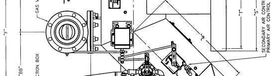
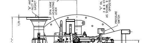
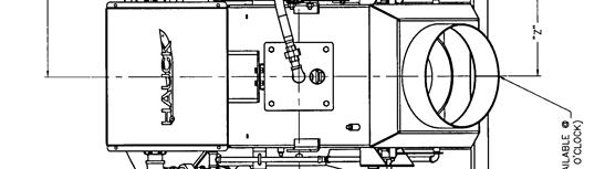
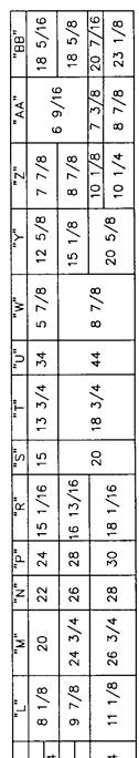
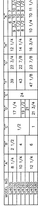
5 D. DIMENSIONS Page 5 Y4060 (NOT TO SCALE) Figure 1. Dimensions SJ075 SJ580
 Page 6 Y4060")

6 D. DIMENSIONS (Continued) Page 6 Y4060 METRIC (NOT TO SCALE) Figure 2. Metric Dimensions SJ075 SJ580
 Page 7")

7 D. DIMENSIONS (Continued) Page 7 Y3351 (NOT TO SCALE) Figure 3. Dimensions SJ750 SJ980
 Figure 4. Metric Dimensions SJ750 SJ980")
8 D. DIMENSIONS (Continued) Page 8 NOTE: 1. ALL DIMENSIONS ARE IN MM. Y3351 METRIC (NOT TO SCALE) Figure 4. Metric Dimensions SJ750 SJ980
9 E. COMPONENT IDENTIFICATION Page 9 Y4135 (NOT TO SCALE) Figure 5. Hauck StarJet Burner and Associated System Components

10 F. BURNER MOUNTING Page 10 X3916 (NOT TO SCALE) Figure 6. Breeching Ring Detail 1. The burner should be mounted on the drum centerline at the same pitch as the drum. Install a structure to support and position the burner's skid. The skid support structure should provide a minimum adjustment of plus or minus 4" (102mm) along the centerline of the drum or breeching ring. Burner repositioning may be required for final burner adjustment. 2. Position the mini-skid on the support and securely bolt it in place. 3. Position the burner so that the distance between the heatshield and the breeching ring (or combustion chamber, if present) is either 5 or 9" (127 or 229mm), dependent on model size (see Figure 6). IMPORTANT The pilot flame UV scanner must be aligned to view just above the pilot as it passes through the flame holder cone. The main flame UV scanner should be sighted just over the edge of the flame holder cone, in line with the flame. 4. Optional Dual Heatshield - Install the two sections of the optional dual heatshield, if applicable, as shown in Figure 7.
11 Page 11 S4020 (NOT TO SCALE) Figure 7. Installation of Dual Heatshield 5. Shim under the burner skid, if necessary, to align the burner horizontal and vertical centerlines with the horizontal and vertical centerlines of the dryer drum (or combustion chamber). The assembled burner must be on the combustion chamber centerline and at the same pitch as the combustion chamber (follow the dryer manufacturer s recommendation for burners used without combustion chambers).
12 Page 12 G. FUEL MANIFOLD INSTALLATION The StarJet burner system is supplied with a separate fuel valve manifold. Depending on fuel or fuels specified, the manifold(s) will be designated as POM - Prepiped Oil Manifold, PGM - Prepiped Gas Manifold, or PLPM - Prepiped Liquid Propane (LP) Manifold. Refer to dimension drawings suppliedfor component dimensions. IMPORTANT Valve manifolds must be mounted in a horizontal position. Valves will not function properly mounted vertically. Liquid fuel manifolds should not be mounted above the burner centerline. POM and PLPM manifold should be mounted as close to the burner as possible. For all heavy fuel oil applications, i.e., any oil requiring heating for use, oil piping must be heat traced (electric or steam) and insulated. Selfregulating heat tracing is recommended to maintain the desired temperature of a given fuel oil to achieve 90 SSU (1.8x10⁻⁵ m 2 /sec) or less at the burner. Electrical heat tracing with a nominal rating of 12 W/ft (39 W/m) covered with a nominal 2" (50mm) fiberglass type insulation is sufficient for most applications. Fuel oil temperature should not exceed 250 F(120 C). Oil viscosity should be checked prior to burner operation. Hauck recommends the use of solid pipe to connect fuel manifolds to the burner fuel inlets. Schedule 40 iron pipe is recommended for gas and oil systems. LP applications require the use of schedule 80 pipe and fittings rated for 350 psig (2410 kpa). Flexible hoses should not be used in LP applications to connect to the burner fuel inlet.
13 H. NATURAL GAS FUEL PIPING SYSTEM Page 13 WARNING It is important to remove the high velocity oil sleeve and install the low velocity gas sleeve in the model burners when firing natural gas. NOTE Hauck recommends the use of gas manifolds that meet NFPA guidelines. NFPA requires two safety shutoff valves wired in series, a shutoff valve downstream of the second (blocking) shutoff valve, and high and low gas pressure switches that are interlocked with the burner s safety shutoff valves. Hauck gas manifolds have been designed to ensure compliance to NFPA requirements. 1. Install a controlling gas regulator in the main gas line within 25 ft (7.6m) of the burner. For optimum control, supply psig ( kpa) to this regulator. This regulator should be sized to provide the required gas flow at the inlet of the burner manifold; 2-5 psig (14-35 kpa) is a nominal expected gas pressure. Exact gas pressures will be set at start-up. 2. A manual equipment isolation valve, sediment trap and gas strainer must be installed upstream of the gas control regulator to ensure compliance to NFPA requirements. The manual equipment isolation valve facilitates servicing of the gas control regulator, sediment trap, strainer, and sediment trap, strainer, and other components in the gas manifold. 3. The gas company should purge the main gas line to remove scale and dirt before it is attached to the burner gas manifold. 4. Connect the main gas line (see Figure 8). IMPORTANT Install a flexible fitting in the gas manifold to reduce flexing of the manifold resulting from plant vibrations. Be sure to install the gas metering orifice section (see Figure 9) provided with the gas valve metering kit to measure gas flow. Excluding the gas metering orifice section will make initial setup and tuning difficult.
 Figure 9.")
14 Page 14 Y4220 (NOT TO SCALE) Figure 8. Typical Schematic of Burner Gas Manifold X4845 (NOT TO SCALE) Figure 9. Dimensions for Gas Metering Orifice
15 5. The piping from the gas regulator outlet to the burner gas manifold should be sized to minimize pressure losses. 6. Check blower rotation. The impeller should rotate toward the blower discharge. 7. Inspect and operate the plant exhaust damper control. The exhaust damper should be capable of maintaining a consistent negative pressure at the drum front bulkhead of negative 0.2 to negative 0.5 "wc (negative 5 to negative 13mm wc) from low to high firing rates for most applications. 8. Install a gas sampling probe in the dryer rear plate (see Application Sheet GJ73). 9. Set the low gas pressure switch to an initial setting of 0.5 psig (3.4 kpa). 10. Set the high gas pressure switch to an initial setting of 5 psig (34.5 kpa). Page Complete the initial adjustment of the gas butterfly valve as follows: The valve is factory set to travel 90 degrees from position 1 to position Run. This travel can be modified to increase or decrease low fire by choosing a lower or higher starting point. 12. Open all manual shutoff valves in the gas line upstream of the gas pressure switch. WARNING Adjustment of this equipment and its components by unqualified personnel can result in fire, explosion, severe personal injury, or even death. 13. Start gas flow to the gas manifold. 14. Adjust the gas regulator until the pressure gauge upstream of the main gas automatic shutoff valves indicates a pressure of 2 psig (13.8 k Pa). 15. High fire can be modified by increasing or decreasing gas pressure. After setting high fire gas pressure, low fire must be rechecked. Refer to individual Burner Gas Orifice Meters Graph for gas flows through the gas orifice meter (see Figure 10). 16. Burner flame adjustment spin vanes can be set at 0 to 60 degrees; 0 degrees narrows the flame, 60 degrees widens the flame, and 30 degrees is a nominal starting point. 17. Burner air adjustments: (see Section P). 18. Recheck all linkages for tightness. 19. Install a U-tube manometer across the gas orifice meter taps. 20. Connect a gas analyzer to the gas sampling probe. 21. Exhaust gas readings should be taken with the burner firing at operating tonnage (see Application Sheet GJ73).
16 Page 16 Q753 Figure 10. Gas Orifice Meters Graph


17 I. LIGHT FUEL OIL PIPING SYSTEM Page 17 WARNING Adjustment of this equipment and its components by unqualified personnel can result in fire, explosion, severe personal injury, or even death. NOTE Hauck requires the use of oil manifolds that meet NFPA guidelines. NFPA requires two safety shutoff valves piped in series in the burner's main oil line. A low/high oil pressure switch must be interlocked with the burner's safety shutoff valves. 1. Light fuel oil supply manifold (see Figure 11 and 12): For recommended piping sizes, see Table 3. For POM oil manifold installation instructions, see Section G. Table 3. Minimum Pipe Size for Hauck Oil Supply Pumping Units
18 Page Before attaching fuel oil lines, purge the piping to remove scale and dirt that could clog and damage oil equipment. 3. Open all shutoff valves upstream of the fuel oil metering valve(s). 4. Be sure that the metering valve(s) is in the low fire position. 5. Open the mini-ball valve to the pressure gauge. 6. Slowly adjust the bypass relief valve until the initial set-up fuel oil pressure is achieved (see Table 4). Final pump pressure will have to be adjusted to attain desired burner output and stack exhaust gas analysis. StarJet Model No. Fuel Oil Pressure w/36 osig (15.5 kpa) Blower psig (310 kpa) psig (345 kpa) psig (310 kpa) psig (345 kpa) psig (345 kpa) psig (345 kpa) psig (550 kpa) psig (485 kpa) psig (550 kpa) Table 4. Fuel Oil Pressures 7. Check rotation of the combustion blower. The impeller should rotate toward the blower discharge. 8. Inspect and operate the plant exhaust damper control. The exhaust damper should be capable of maintaining a consistent negative pressure at the drum front bulkhead of negative 0.2 to negative 0.5 "wc (negative 5 to negative 13mm wc) from low to high firing rates for most applications. 9. The low/high oil pressure switch is factory set at a low set point of 15 psig (103 kpa) and a high set point of 80 psig (552 kpa). Set point adjustments may be required depending on the burner and fuel oil piping specifics. 10. Inspect the complete fuel oil system for leaks. Repair as necessary. 11. The burner oil metering valve is factory set to travel 90 degrees from position 1 to The low fire oil valve is manually set and regulates low fire flow. This valve can easily be changed to regulate low fire oil flow. Start this valve at position 9. The low fire valve can easily be cleaned: a. Mark the valve pointer position. b. Turn the valve counterclockwise to the 'clean' position. c. Return the valve pointer to its original position.
19 13. High fire oil flow can be adjusted by increasing or decreasing fuel oil pressure. After changing fuel oil pressure, low fire flow should be rechecked. Low and high fire rates in gal/min or liters/min can be checked and recorded with the in-line oil flow meter provided with the prepiped oil manifold. Page Burner flame spin vane adjustment can be set at 0 to 60 degrees. 0 degrees narrows the flame, 60 degrees widens the flame, and 30 degrees is a nominal starting point. 15. Burner air adjustments: (see Section P). 16. Recheck all linkages for tightness. 17. Connect a gas analyzer to the gas sampling probe (see Application Sheet GJ73). Exhaust gas readings should be taken at operating tonnage. X6263 (NOT TO SCALE) Figure 11. Typical Schematic of Burner Light Fuel Oil Piping
20 Page 20 NOTE Oil manifold must be mounted in a horizontal position. Mount as close to the burner as possible. Mount manifold below the burner s center-line. X6189 (NOT TO SCALE) J. HEAVY FUEL OIL PIPING SYSTEM Figure 12. POM Prepiped Oil Manifold Detail WARNING Adjustment of this equipment and its components by unqualified personnel can result in fire, explosion, severe personal injury, or even death. Heated fuel oil and piping is hot. Precautions must be taken to prevent contact with heated oil and piping. Proper insulation should be installed on hot oil pipes. Protective gloves and clothing are recommended when working with heated fuel oil. IMPORTANT For all heavy fuel oil applications, i.e., any oil requiring heating for use, oil piping must be heat traced (electric or steam) and insulated. Self-regulating heat tracing is recommended to maintain the desired temperature of a given fuel oil to achieve 90 SSU (1.8 x 10⁻⁵ m 2 /sec) or less at the burner. Electrical heat tracing with a nominal rating of 12W/ft (39W/m) covered with a nominal 2" (50mm) fiberglass type insulation is sufficient for most applications.
21 Page 21 NOTE Hauck recommends the use of oil manifolds that meet NFPA guidelines. NFPA requires two safety shutoff valves piped in series in the burner's main oil line. A low/high oil pressure switch must be interlocked with the burner's safety shutoff valves. When preheated oil is used, a low/high oil temperature limit switch must be interlocked to the burner's oil safety shutoff valves. Hauck's oil manifolds have been designed to ensure compliance to NFPA requirements. 1. Heavy fuel oil supply piping and manifold (see Figure 13 and 14): For recommended piping sizes, see Table 4. For POM-H oil manifold installation instructions, see Section G. 2. Fuel oil used must be 90 SSU (1.8 x 10⁻⁵ m 2 /sec) or less for proper atomization and burning. Use a Hauck viscometer kit (order separately Part No ) to determine the proper oil temperature for 90 SSU. 3. Set the fuel oil heater temperature set point and the indicating low oil temperature switch (located on the burner's oil manifold) to the temperature determined from Step Before attaching fuel oil lines, purge the piping to remove scale and dirt that could clog and damage oil equipment. 5. Open all shutoff valves upstream of the fuel oil metering valve(s). 6. Open the mini-ball valve to the pressure gauge. 7. Start the pump and heating medium. 8. Close the manual ball valve immediately downstream of the normally open solenoid in the heavy oil recirculating line. 9. Adjust the bypass relief valve on the pump set until the initial set-up oil pressure is achieved (see Table 4). Final pump pressure will have to be adjusted to attain desired burner output and stack exhaust gas analysis. 10. Open the manual ball valve in the heavy oil recirculating line. 11. Using the low/high oil temperature indicating switch located on the burner, verify that the fuel oil is at the desired temperature from Step 2. Adjust the heater until the proper fuel oil temperature is attained at the burner. 12. Check and repair all fuel oil leaks. 13. The burner oil metering valve is factory set to travel 90 degrees from position 1 to The low fire oil valve is manually set and regulates low fire flow. This valve can easily be changed to regulate low fire. Start this valve at position 9. The low fire valve can easily be cleaned: a. Mark the valve pointer position. b. Turn the valve counterclockwise to the 'clean' position. c. Return the valve pointer to its original position.
22 15. High fire can be modified by increasing or decreasing fuel oil pressure or by changing the maximum oil metering valve stroke. After changing fuel oil pressure, low fire should be rechecked. 16. Check rotation of the combustion blower. The impeller should rotate toward the blower discharge. 17. Inspect and operate the plant exhaust damper control. The exhaust damper should be capable of maintaining a consistent negative pressure at the drum front bulkhead of negative 0.2 to negative 0.5 "wc (negative 5 to negative 13mm wc) from low to high firing rates for most applications. 18. The low/high oil pressure switch is factory set at a low set point of 15 psig (103 kpa) and a high set point of 80 psig (552 kpa). Set point adjustments may be required depending on the burner and fuel oil piping specifics. 19. Burner flame spin vanes adjustment can be set at 0 to 60 degrees; 0 degrees narrows the flame, 60 degrees widens the flame, and 30 degrees is a nominal starting point. 20. Burner air adjustments: (see Section P). 21. Recheck all linkages for tightness. 22. Install a gas sampling probe in the dryer drum rear (see Application Sheet GJ73). 23. Connect a gas analyzer to the gas sampling probe (see Application Sheet GJ73). Exhaust gas readings should be taken at operating tonnage. Page 22
 Figure 13.")

23 Page 23 Y6264 (NOT TO SCALE) Figure 13. Typical Schematic of Burner Heavy Fuel Oil Piping
24 Page 24 NOTE Oil manifold must be mounted in a horizontal position. Mount as close to the burner as possible. Mount manifold below the burner s center-line. X6210 (NOT TO SCALE) Figure 14. POM-H Prepiped Heavy Oil Manifold Detail K. HEAVY OIL INSERT HEATER Heavy, waste, or recycled fuel oils require some means of viscosity control. The Hauck Heavy Oil Insert Heater installed in the burner nozzle supply line is a perfect solution to the viscosity control problem and reliable main flame ignition of the burner at cold temperatures. The heavy oil insert heating element, in conjunction with the oil temperature indicating controller, will maintain an optimum oil temperature in the oil tube to ensure a reliable burner main flame ignition after an extended shutdown of the burner. W7655 (NOT TO SCALE) Figure 15. Heavy Oil Insert Heater
25 Page 25 NOTE 120V/60Hz power for the heavy oil insert heater must be supplied separately by the customer and wired into the heater junction box. Operation of the heavy oil insert kit is as follows (see Figure 15): 1. Adjust the low temperature controller to the desired temperature as determined in Section K from testing of the heavy oil viscosity. NOTE Adjusting the trip setpoint above the required temperature, as determined by fuel oil viscosity testing, may result in coking of the fuel oil in the insert oil piping. 2. Energize the insert heater circuit breaker switch. 3. When the oil temperature exceeds the setpoint on the oil temperature indicating controller, the oil temperature indicating controller switch contact will open and power to the heater element is removed. 4. When the oil temperature drops below the setpoint on the oil temperature indicating controller, the oil temperature indicating controller switch contact will close and the heater element will energize. See SJ-9.2 StarJet Heavy Oil Insert Heater Kit Instructions for more specific detail on the operation and maintenance of the heavy oil insert heater.
26 Page 26 L. FUEL OIL NOZZLE ADJUSTMENT The position of the fuel oil nozzle affects its ability to atomize the oil. The low pressure nozzle or compressed air nozzle should be positioned as shown in Figure 16. To change the fuel oil nozzle position: Figure 16. Oil Nozzle Position 1. Shut the oil valve upstream of the safety shutoff valves. 2. Disconnect the burner oil insert assembly from the oil valve manifold, using the union located downstream of the flexible hose. 3. Note the present orientation of the nozzle while assembled in the burner. Determine if the nozzle must be retracted into or extended out of the primary air tube (see Figure 16). 4. Remove the four bolts securing the backplate to the burner. 5. Loosen the jam nut on the backplate of the burner oil insert assembly. 6. Rotate the backplate to effect the required retraction or extension of the nozzle. One full rotation of the backplate will move the nozzle approximately 0.1" (2.5mm). 7. Once the proper positioning of the nozzle is completed: a. Tighten the jam nut. b. Attach the burner oil insert assembly to the oil valve manifold, using the union provided. c. Open the oil valve upstream of the safety shutoff valves. X7639 (NOT TO SCALE)
27 Page 27 M. COMPRESSED AIR/OIL SYSTEM The Hauck high pressure oil nozzle is designed to finely atomize No. 2 fuel oil and clean preheated No. 4, No. 5 and No. 6 fuel oil. Oil viscosity should be 90 SSU (1.8 x 10⁻⁵ m 2 /sec) or less. Preheat fuel oil and heat trace piping when using No. 4, No. 5, and No. 6 fuel oil to achieve 90 SSU oil at the burner (see Compressed Air/Oil Adjustment). Care should be taken to insure that the air and oil supplied to the burner are free of dirt particles and water. Purge oil and air lines before connecting them to the compressed air/oil insert. The nozzle should be inspected and cleaned before the start of each session and possibly more depending on the cleanliness of the air and fuel. COMPRESSED AIR PIPING 1. The compressed air supply line must be of adequate size (see Table 5) and be a dedicated line from the compressor to the burner compressed air inlet. For longer piping runs than those listed in the table, increase the hose by one pipe size. Before attaching lines, purge the hose to remove any dirt that could clog and damage the oil nozzle. StarJet Model No. Min. Hose Size Max. Hose Length /4 NPT (DN 20) 70 ft (21 m) NPT (DN 25) 160 ft (49 m) NPT (DN 25) 90 ft (27 m) Table 5. Flexible Air Hose Size Requirements 2. Compressed air requirements are listed in Table 6. Compressed air must be supplied to the inlet of the compressed air manifold at a minimum of 90 psig (620 kpa). The compressed air regulator modulates the compressed air flow as oil flow is modulated to reduce compressed air consumption at lower firing rates. NOTE The compressed air low supply pressure switch and low atomizing pressure switch must both be interlocked with the burner s oil safety shutoff valves. The compressed air solenoid valve is normally wired in parallel with the burner s safety shutoff valves. Reference the control panel drawings for wire and/or terminal numbers.
28 Page 28 StarJet Model No Oil Pressure To Burner Nozzle Compressed Air Pressure to Burner Nozzle Firing Rate Oil Flow Compressed Air Flow (gpm) (lpm) (psig) (kpa) (scfm) (nm 3 /min) (psig) (kpa) High Fire % % Low Fire High Fire % % Low Fire High Fire % % Low Fire High Fire % % Low Fire High Fire % % Low Fire High Fire % % Low Fire High Fire % % Low Fire High Fire % % Low Fire Table 6. Compressed Air and Oil Requirements
29 Page 29 COMPRESSED AIR/OIL ADJUSTMENT 1. Air and fuel flows and pressures can be observed at the burner using the compressed air and fuel flow meters and corresponding pressure gauges (see Figure 17). 2. Compressed air supply pressure to the inlet of the compressed air manifold must be 90 psig (620 kpa) or greater. The supply pressure is measured via the gauge on the inlet to the compressed air flow meter (see Figure 17). The compressed air low supply pressure switch is preset at 60 psig (414 kpa). Set point adjustment may be required depending on the burner and compressed air piping specifics. Figure 17. Compressed Air Manifold Detail X7303 (NOT TO SCALE) 3. For the compressed air manifold to function properly, the impulse line and upper chamber of the pressure reducing regulator must be loaded with oil by opening the vent valve on the regulator until oil vents, then closing the vent valve. 4. Final compressed air flow and pressure adjustment is made via the compressed air trim valve (see Figure 17). With the burner at high fire, adjust the trim valve until the compressed air burner inlet pressure gauge, located downstream of the trim valve, reads approximately 60 psig (414 kpa). The compressed air low atomizing air switch is preset at 5 psig (34.5 kpa). Set point adjustment may be required depending on the burner and compressed air piping specifics. 5. Compressed air flow can be read directly from the compressed air flow meter. Refer to Compressed Air Flow Meter section and Figure 19 for detailed instructions on how to read the compressed air flow meter. Verify that both the compressed air flow and burner inlet pressure, from step 4, meet or exceed the values given in Table 6 and/or the additional burner capacity and performance data sheets.
30 Page 30 IMPORTANT For all heavy fuel oil applications, i.e., any oil requiring heating for use, oil piping must be heat traced (electric or steam) and insulated. Self-regulating heat tracing is recommended to maintain the desired temperature of a given fuel oil to achieve 90 SSU (1.8 x 10⁻⁵ m 2 /sec) or less at the burner. Electrical heat tracing with a nominal rating of 12W/ft (39W/m) covered with a nominal 2" (50mm) fiberglass type insulation is sufficient for most applications. W7346 (NOT TO SCALE) Figure 18. Compressed Air/Oil Insert Assembly The compressed air insert assembly is inserted in the primary air tube. Tighten the rear flange bolts. The nozzle can be adjusted to maintain the 1/16" (1.6mm) dimension shown in Figure 18. COMPRESSED AIR FLOW METER The compressed air flow meter is offered with a standard multi-pressure flow scale. The multi-pressure flow scale has a vertically graduated scale, calibrated for air in standard cubic feet per minute (scfm) at 1.0 s.g. (70 F at 100 psig); also available in a metric version in liters per second (lps) at 1.0 s.g. (21 C at 6.9 bar). The multi-pressure scale design allows for use at supply pressures from psig in 10 psig increments (metric version from bar in 1 bar increments). To determine the compressed air flow rate, refer to Figure 19 and proceed as follows: 1. Read the inlet pressure on the pressure gauge of the compressed air flow meter. 2. Select the appropriate inlet pressure (psig) vertical line, or interpolated value closest to the gauge reading, and follow the line upward until it intersects the brightly colored horizontal indicator bar. 3. From the intersecting point on the horizontal indicator bar, follow the slope as shown on the diagonal lines to the 100 psig inlet pressure vertical line and interpolate the scfm or lps flow rate (Note for the example shown in Figure 19, with an inlet pressure of 60 psig, the compressed air flow rate is approximately 40 scfm).


. 4.")

31 Page 31 Figure 19. Compressed Air Flow Meter and Scale To change the compressed air/oil nozzle position. 1. Ensure that the burner is not firing, then close the manual oil valve and the manual compressed air ball valve at the burner. CAUTION If heated heavy oil is being used, allow the oil in the pipe to cool to avoid burns. 2. Drain residual fuel into an appropriate container. 3. Inspect the present orientation of the air/oil nozzle in the burner. Determine if the air/oil nozzle must be moved in or out to maintain the proper distance (see Figure 18). 4. Loosen the nozzle adjusting nuts located on the compressed air/oil insert backplate (see Figure 18). 5. Slide the compressed air/oil insert assembly to achieve the required retraction or extension of the air/oil nozzle. 6. Once the proper positioning of the air/oil nozzle is completed: a. Tighten the nozzle adjusting nuts on the backplate. b. Attach the oil inlet on the compressed air/oil insert assembly to the oil valve manifold. c. Open the manual oil valve. Check for leaks using accepted leak check practices.
32 N. LIQUID PROPANE (LP) FUEL PIPING SYSTEM Page 32 WARNING Adjustment of this equipment and its components by unqualified personnel can result in fire, explosion, severe personal injury, or even death. LP is highly flammable and heavier than air. It will accumulate near the ground in the area of a leak and it dissipates relatively slowly. NOTE Hauck recommends the use of LP manifolds that meet NFPA guidelines. NFPA requires two safety shutoff valves piped in series in the burner's main LP line. A low/high pressure LP switch must be interlocked with the burner's safety shutoff valves. Hauck's LP manifolds have been designed to ensure compliance to NFPA requirements. 1. Before attaching LP fuel lines, purge the lines with compressed air. Then, leak test piping with compressed air. 2. Connect the main LP line at the appropriate connection on the burner skid. All piping must be schedule 80 black iron or heavier and all valving must be suitable for 350 psig (2410 kpa) service. The capacity of the LP fuel system should be 1.5 times the rated capacity of the burner. 3. If Hauck has supplied the LP pump set for this application, consult the pump installation instructions for information on this unit.

33 Page 33 Y4059 NOT TO SCALE) Figure 20. Typical Schematic of LP Piping
34 Page 34 NOTE LP manifold must be mounted in a horizontal position. Mount as close to the burner as possible. Mount manifold below the burner s center-line. X6190 (NOT TO SCALE) Figure 21. PLPM Prepiped LP Manifold Detail WARNING Hauck does not recommend installation of a line-reducing regulator in the LP supply line. If the regulator diaphragm were to rupture, total system pressure would be applied to the burner and could result in damage to equipment, including the baghouse, and result in serious injury to personnel. CAUTION Hauck strongly recommends that a bypass flow control valve and a backpressure regulator (available from Hauck) be installed in all LP systems and piped as shown in Figure 20. All components must be rated for 350 psig (2410 kpa) for LP use. 4. Close the manual ball valve upstream of the PLPM manifold (see Figure 21). 5. Open the manual shutoff valve on the inlet side of the pump. 6. Turn on the LP pump to start LP flow. 7. Check all LP lines and connections for leaks following accepted standards and practices. 8. Open the manual ball valve upstream of the PLPM manifold and check the manifold for leaks (see Figure 21). After burner has been ignited and LP is flowing to the burner nozzle, check all piping for leaks.
35 Page 35 WARNING Frost or icing is an indication of an LP leak. It is possible for a leak to occur without such evidence. Although the LP supply is initially in a liquid state, as it is vaporized it becomes heavier than air and accumulates near the ground and dissipates relatively slowly, becoming highly flammable. Extreme care should be exercised with LP fuels and systems. NOTE The system shown in Figure 20 is designed for optimum performance at ambient air temperatures above 40 F (5 C). For operation at temperatures below 40 F, consult Hauck for recommendations. 9. Adjustment of LP supply pressure: a. Install an amp probe on the LP pump power supply line. CAUTION Do not exceed the maximum LP pump motor nameplate amp load at any time while making adjustments. b. Close the ball valve between the backpressure regulator and the tank to temporarily take the regulator out of the system (see Figure 20). c. Adjust the bypass flow control valve to the following initial settings: 100% Commercial Propane 235 psig (1620 kpa) 50/50 Propane/Butane 170 psig (1170 kpa) 100% Butane 95 psig (655 kpa) NOTE If pump motor nameplate amperage is exceeded, reduce pressure in Step 9.c to below nameplate amp rating. d. Reopen the bypass flow control valve closed in Step c.
36 Page 36 e. Adjust the backpressure regulator to the following initial settings: 100% Commercial Propane 210 psig (1450 kpa) 50/50 Propane/Butane 145 psig (1000 kpa) 100% Butane 70 psig (480 kpa) NOTE If motor amperage in Step 9.c exceeded nameplate amp rating, set backpressure regulator at 25 psig (172 kpa) less than the bypass flow control valve setting. These settings are initial settings only. Settings are based on 60 F (15.5 C) fuel temperature plus normal pump pressure; pump differential pressure = 100 psig (700 kpa). Settings will have to be readjusted for changes in temperature and operation. The bypass flow control valve should always be set approximately 25 psig (172 kpa) above the backpressure regulator to insure pump protection. 10. a. Be sure the LP metering valve is in the low fire position. This valve is factory set to travel approximately 90 degrees starting at position 1 to 10. These positions can be modified to adjust to a higher or lower firing rate. If adjusting high fire, low fire must be reset. b. Read and record LP metering valve settings and flow rates using the in-line LP flow meter (gal/min or liters/min LP liquid) provided with the burner. 11. Check rotation of the combustion blower. The impeller should rotate toward the blower discharge. 12. Inspect and operate the plant exhaust damper control. The exhaust damper should be capable of maintaining a consistent negative pressure at the drum front bulkhead of negative 0.2 "wc to negative 0.5 "wc ( negative 5 to negative 13mm wc) from low to high firing rates for most applications. 13. The low/high LP pressure switch is factory set at a low set point of 165 psig (1140 kpa) and a high set point of 230 psig (1590 kpa). Set point adjustments may be required depending on the burner and LP piping specifics. 14. Burner flame spin vanes adjustment can be set at 0 to 60 degrees; 0 degrees narrows the flame, 60 degrees widens the flame, and 30 degrees is a nominal starting point. 15. Burner air adjustments: (see Section P). 16. Install a gas sampling probe in the dryer drum rear (see Application Sheet GJ73). 17. Connect a gas analyzer to the gas sampling probe (see Application Sheet GJ73). Exhaust gas readings should be taken at operating tonnage.
37 Page 37 NOTE Different nozzles are required when burning liquid propane, butane, or a mixture of propane/ butane. Consult Hauck for your specific fuel nozzle requirements. WARNING Do not attempt to reposition the LP nozzle while the burner is firing. Considerable pressure exists under firing conditions. Attempting to adjust the LP nozzle while the burner is firing may result in equipment damage or injury to personnel. Figure 22. LP Nozzle Position X7639 (NOT TO SCALE) To change the LP nozzle position: 1. Shut the LP manual ball valve upstream of the LP safety shutoff valves. 2. Disconnect the burner LP insert assembly from the LP valve manifold, using the union located downstream of the flexible hose. 3. Note the present orientation of the LP nozzle while assembled in the burner. Determine if the nozzle must be retracted into or extended out of the primary tube (see Figure 22).
38 Page Remove the four bolts securing the backplate to the burner. 5. Loosen the jam nut on the backplate of the burner LP insert assembly. 6. Rotate the backplate to effect the required retraction or extension of the nozzle. One full rotation of the backplate will move the nozzle approximately 0.1" (2.5mm). 7. Once the proper positioning of the nozzle is completed: a. Tighten the jam nut. b. Attach the burner LP insert assembly to the LP valve manifold, using the union provided. c. Open the LP valve upstream of the safety shutoff valves.
39 Figure 23. Vapor Pressures of Propane, Butane & Butane-Propane Mixtures Page 39
40 Page 40 O. BURNER PILOT SYSTEM The StarJet Burner incorporates an air inspirited via gas (AIG) pilot system (see Figure 24). The pilot and UV scanners should always be oriented to point downward. As delivered, the pilot and UV scanners should be properly oriented, based on the air inlet orientation specified when the burner was ordered. Adjustment and operation of the pilot system is detailed below. 1. Before connecting to the pilot, the gas line should be purged to remove any dirt. Connect the pilot gas supply line to the inlet of the pilot gas shutoff valve. Size the pilot gas supply line to avoid excessive pressure drops. For pilot gas supply lines up to 25 ft (7.6m), use 1/2 NPT (DN 15) or larger piping. 2. Constant gas pressures ranging from 15 psig (103 kpa) minimum to 25 psig (172 kpa) maximum must be available at the inlet of the Hauck gas pilot manifold. Y4061 (NOT TO SCALE) Figure 24. Pilot Manifold Detail 3. The spark wire gap is factory set at 1/8" (3 mm). This gap can be changed by carefully removing the pilot internals. Bend the spark wire to adjust, reinsert, and check the gap. For field adjustments, a U.S. 5 coin with 0.08" (2 mm) thickness can be used as a gauge for adjusting the spark gap. 4. Complete the initial pilot adjustment of the air shutter as follows (see Figure 25): a. Loosen, but do not remove, the locking thumbscrew. b. Adjust the air shutter to approximately 1/4" (6.4mm) gap opening. c. Securely tighten the locking thumbscrew. d. Slowly open the gas flow valve and light the pilot by means of electric ignition.
41 Page 41 W7404 (NOT TO SCALE) Figure 25. Pilot AIG Inspirator W7403 (NOT TO SCALE) Figure 26. Pilot Scanner & Adapter P. OPERATION WARNING Adjustment of this equipment and its components by unqualified personnel can result in fire, explosion, severe personal injury, or even death. 1. The StarJet air/fuel system uses a single control motor for modulation of burner air and fuel. This control motor travels 90 from low to high fire, driving both the burner air and fuel valves simultaneously. 2. Only 40% of total required burner air is passed through the burner; this includes burner primary air which is on at all times on all fuels, and secondary air. The remaining air for combustion is pulled past the burner cone by the plant exhaust system.
42 Page The plant exhaust fan must be running with it s damper open sufficiently for the proper purge time. The minimum purge time is the time required for four volumes of air to flow through the entire combustion and exhaust system (including the baghouse and exhaust stack). 4. A constant negative 0.25"wc (6.3mm wc) draft is important in maintaining a constant air flow past the burner without puffing the drum front. This negative pressure can easily be maintained with a Hauck DPS digital pressure control system. The negative pressure tap should be located on the drum front bulkhead between the burner and the O.D. of the drum at the burner centerline. 5. Prior to light off, ensure that the secondary air low fire limit switch (see Figure 27) is set so the switch contacts are closed (engaged) by the bottom of the pointer. When the burner is positioned above low fire, the switch contacts should open. Consult control panel instructions for wire and/or terminal numbers. 6. Ensure that the low fire fuel limit switches, located on the respective fuel manifolds, are set to have closed contacts when the fuel valve is at low fire. 7. Initial burner component settings for all fuels are presented in Table 7 and 8, and should be verified prior to burner light off. 8. When making any adjustments to the burner, exhaust gas measurements should be taken to verify that complete combustion is taking place (see Application Sheet GJ73 for general information on conducting exhaust gas analysis). S4021 (NOT TO SCALE) Figure 27. Low Fire Limit Switch


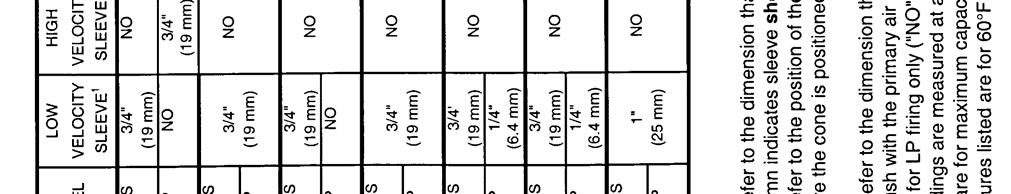
43 Table 7. Initial Burner Component Settings for Natural Gas & LP Page 43


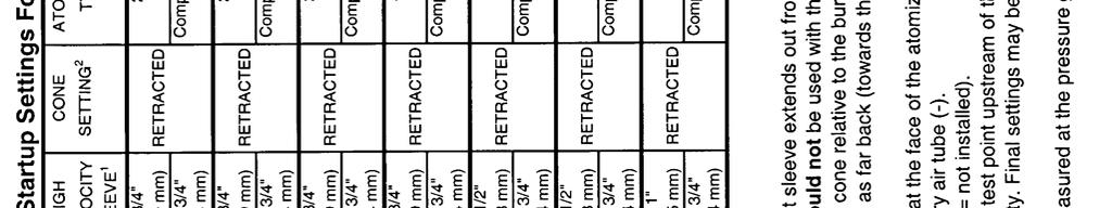
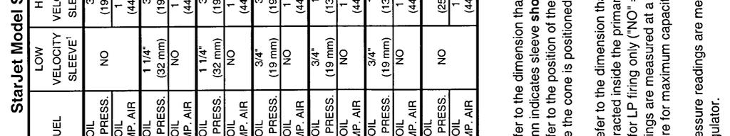
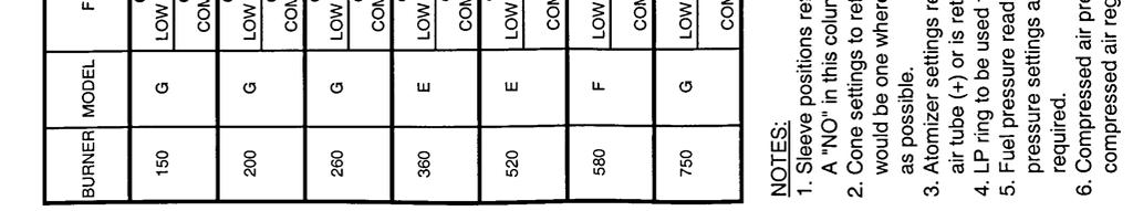
44 Table 8. Initial Burner Component Settings for Oil Page 44
45 Page 45 Q. FLAME SHAPE ADJUSTMENTS There are two devices on the burner which can affect the flame shape: the spin vane adjustment ring and the secondary air sleeve. The spin vane adjustment ring is the principle means of adjusting flame shape. The spin vane adjustment ring uniformly adjusts the angle of the secondary air spin vanes which impart spin to the secondary air stream as it leaves the burner. These vanes, when set at an angle, increase the air/fuel mixing rate and produce a shorter, bushier flame. The effect can be minor or severe, depending on the angle setting of the vanes. The greater the angle (adjustable from 0-60 degrees), the shorter and bushier the flame. The amount of secondary spin is read on the spin vane indicator, mounted on the spin vane setting indicator plate. In some applications, high spin may cause overheating of the drum front bulkhead and combustion zone flights. In such cases, reduce the spin angle as necessary until such condition is eliminated. Spin Vane Adjustment: 1. Shut down the burner system. 2. Loosen the locking bolt and using the spin vane adjusting lever, rotate the ring until the spin vane indicator reads 30 degrees. 3. Tighten the locking bolt. Burners Equipped With Secondary Air Sleeve: The secondary air sleeve prevents the free expansion of the secondary air as it leaves the secondary air tube. This concentrates the secondary air, which improves the atomization of fuel oil. The farther the sleeve is extended, the narrower the flame becomes. Typically, the sleeve should not be extended more than 3/4" (19 mm). The optimal sleeve position is dependent on the specific fuel used and is more critical with heavy oil. If the sleeve is not extended far enough, the oil may not be atomized fully and cause a dark flame. On heavy oil, if the sleeve is extended too far, the atomized oil spray will impinge and deposit on the sleeve. Refer to the start-up settings, Tables 8 and 9, for nominal sleeve settings. WARNING The HIGH VELOCITY secondary air sleeve is for use with: OIL FIRING MODEL LP FIRING SJ150 GAS FIRING NOT USED WITH GAS FIRING ON ANY BURNER MODEL If your application requires a HIGH VELOCITY SLEEVE for oil firing, be sure to remove the HIGH VELOCITY SLEEVE for natural gas firing. If you are unsure which model sleeve is installed on your burner, consult Hauck.
STARJET BURNER SJ075 SJ980
 CAPACITIES STARJET BURNER SJ075 SJ980 Burner Model Air Flow (scfm) Pressure (osig) 36 osig 60 Hz Direct Drive Blowers TBA Blower Motor Model HP Fan Rating (acfm @ 350 F) Max. Capacity (MMBtu/hr) SJ075
MEGASTAR TM BURNER MS-25 MS-150
 INSTRUCTIONS MEGASTAR TM BURNER MS-25 MS-150 WARNING These instructions are intended for use only by experienced, qualified combustion startup personnel. Adjustment of this equipment by unqualified personnel
PBG PACKAGED GAS BURNER
 INSTRUCTIONS PBG PACKAGED GAS BURNER WARNING These instructions are intended for use only by experienced, qualified combustion start-up personnel. Adjustment of this equipment and its components by unqualified
NOZZLE MIX COMBINATION BURNER NMC200 SERIES
 NOZZLE MIX COMBINATION BURNER NMC200 SERIES INSTRUCTIONS WARNING These instructions are intended for use only by experienced, qualified combustion start-up personnel. Adjustment of this equipment and its
NMG NOZZLE MIX GAS BURNERS
 INSTRUCTIONS NMG NOZZLE MIX GAS BURNERS WARNING These instructions are intended for use only by experienced, qualified combustion start-up personnel. Adjustment of this equipment and its components, by
LHE OIL LINE HEATER ELECTRIC TYPE
 INSTRUCTIONS LHE OIL LINE HEATER ELECTRIC TYPE WARNING These instructions are intended for use only by experienced, qualified combustion start-up personnel. Adjustment of this equipment and its components
Specifications of V-Line burners
 Duct Burners - V-Line 4-22.5-7 Specifications of V-Line burners V-Line burner firing on natural gas - constant combustion air 60 F - 21% O 2 combustion air - 50% rel. humidity - natural gas with 1000 Btu/ft³
NMC Nozzle Mix Gas/Oil Combination Burners
 NMC Nozzle Mix Gas/Oil Combination Burners NMC-1 Edition 10-08 Burns most gaseous fuels and No. 2 oil Sealed-in capability Stable flame over entire operating range Preheated air to 800ºF (425ºC) Gas pilot
OPERATING AND MAINTENANCE MANUAL
 OPERATING AND MAINTENANCE MANUAL NVPOM-0104 TABLE OF CONTENTS Section Page 1 SPECIFICATIONS...1 1.1 Nova Plus Specifications...1-1 1.2 Warranty...1-2 2 GENERAL BURNER DESCRIPTION...2 2.1 Burner...2-1 2.2
Installation Instructions
 Model 500-SP OVENPAK Burners Page 2300-S-1 Installation Instructions General Instructions Important: Do not discard packing material until all loose items are accounted for. To prevent damage in transit,
Internet Version for Reference Only INDUCED DRAFT COMMERCIAL WATER HEATERS SUPPLEMENT INSTRUCTIONS TO PART #
 INDUCED DRAFT COMMERCIAL WATER HEATERS SUPPLEMENT INSTRUCTIONS TO PART #238-39387-00 THIS INSTRUCTION SUPPLEMENT IS ONLY INTENDED TO GIVE INSTALLATION INSTRUCTIONS AND INFORMATION RELATED TO THE INDUCED
Installation & Service Instructions for Jackson & Church Flexaire Packaged Furnaces SDF-125 thru SDF-400 Gas Firing
 Installation & Service Instructions for Jackson & Church Flexaire Packaged Furnaces SDF-125 thru SDF-400 Gas Firing Important: To protect the unit and avoid damage to the heat exchanger, the blower speed
Product Information. Model: HG, HL, HLG Burner Sizes: 10, 13, 15, 17, 20, 21, 25 GENERAL DESCRIPTION U.L. STANDARD EQUIPMENT
 The H/Series gas, oil, and combination gas/oil burner is a forced draft packaged burner system. A backward curved impeller mounted in a machined housing provides combustion air for various furnace pressures
DESCRIPTION, CAPACITIES, SPECIFICATIONS, APPLICATIONS
 INTEGRAL FAN BURNERS 43, 53, 63 Supplement 600- July 996 DESCRIPTION, CAPACITIES, SPECIFICATIONS, APPLICATIONS Integral Fan (and) Shutter Section (hinged for quick access to internals) Combustion Air Interlock
ECLIPSE INFORMATION GUIDE
 ECLIPSE INFORMATION GUIDE EXTENSO-JET SMALL BORE BURNERS Info 230 8/91 CONTENTS PAGE CONTENTS PAGE Safe Burner Operation... 2 1.0 Applications... 2 2.0 Burner Operating Parameters & Requirements 2.1 Capacities
Engineering Bulletin. Gas Heat. for M-Series and T-Series Climate Changer Air Handlers CLCH-PRB010-EN. March 2004
 Engineering Bulletin Gas Heat for M-Series and T-Series Climate Changer Air Handlers March 2004 CLCH-PRB010-EN Preface Gas heat can be a good heating option for any of the following applications: Climates
APX. Nozzle-mix line burner
 APX Nozzle-mix line burner Duct burners - APX Burner 4-21.9-1 Nozzle-mixing line burner for use with low pressure natural gas, propane and butane Eliminates leakage with its single-piece, aluminium extrusion
ClearFire. Startup Guide. Model CFH. Horizontal Steam Boiler
 ClearFire Model CFH Horizontal Steam Boiler Startup Guide 750-293 www.cleaverbrooks.com Improper installation, adjustment, service, or maintenance can cause equipment damage, personal injury, or death.
Eclipse AirHeat Burner
 135 Design Guide 6/16/2010 Eclipse AirHeat Burner AH Serie Version 2 Copyright Copyright 1999 by Eclipse, Inc. All rights reserved worldwide. This publication is protected by federal regulation and shall
"HC" AIRFLO. In-duct firing line burner
 "HC" AIRFLO In-duct firing line burner -.- High heat release up to.5 MW per unit of burner length (05 mm) Clean combustion with low CO and NO x emission levels Minimal process air pressure drops locally
ECLIPSE INFORMATION GUIDE
 ECLIPSE INFORMATION GUIDE JUNIOR INDUSTRIAL BURNERS Models 0 & 6 JIB Info 80 0/9 Easy to install and operate. Rugged construction for long life in industrial environments. Protection against overheating
INDUSTRIAL MICRODIFFUSION OIL BURNERS
 Operations and Maintenance Manual for INDUSTRIAL MICRODIFFUSION OIL BURNERS Models MD-25-O MD-2500-O December 2012 Copyright 2012 Periflame, Design Guide 112 Industrial Oil Burners, 12/01/2012 Page 1 Table
Cambridge Engineering, Inc. 24 S-Series Technical Manual
 Start-Up Instructions START-UP PROCEDURE 1. Visual Inspection Of Equipment (page 24) 2. Electrical Supply Voltage Verification (page 24) 3. Gas Supply Pressure Verification (page 24) 4. Blower Rotation
Columbia Boiler Company
 EMG Series Boilers Available in Natural Gas & Propane Rev 12012 Columbia Boiler Company PO Box 1070 Pottstown, PA 19464 Tel (610) 473-8457 Fax (610) 367-6800 Website www.columbiaboiler.com Email cbcsales@ptd.net
INSTALLATION, OPERATING & MAINTENANCE INSTRUCTIONS FOR 350 SERIES CIRCULATION HEATERS
 INDEECO Circulation Heaters are designed to provide years of trouble free operation if properly installed and maintained. Please read and follow these instructions for installing and maintaining the heater.
Power Flame Incorporated
 Power Flame Incorporated HAC INSTALLATION AND OPERATION MANUAL THE POWER TO MANAGE ENERGY 2001 South 21 st Street, Parsons, Kansas 67357 Telephone 620-421-0480, Fax 620-421-0948 Web Site: www.powerflame.com
DELTA-TE III. Nozzle-mix line burner
 4-21.7-1 DELTA-TE III Nozzle-mix line burner Combines excellent flexibility with extreme low emissions for direct firing Especially designed for firing in low oxygen, high humidity and/or inert process
LGB Gas fired boiler
 LGB Gas fired boiler Control Supplement LGB-5 Series 2 Propane gas CSD-1 Control System Part Number 550-110-682/0304 Please read this page first Hazard definitions To the installer... The following terms
Preventative Maintenance Tables
 Preventative Maintenance Tables Table of Contents I. Table : Gas Fired Domestic Hot Water Heater II. III. IV. Table : Circulating Pump Table : Convectors Table 4: Grille and Diffusors V. Table 5: Unit
INSTALLATION & MAINTENANCE MANUAL FOR QuickDraw
 INSTALLATION & MAINTENANCE MANUAL FOR QuickDraw SEMI-INSTANTANEOUS ENERGY: STEAM TO WATER U-TUBE SINGLE-WALL & DOUBLE-WALL HEAT EXCHANGERS FLOOR DRAIN Typical Construction Figure 34-1 FLOOR DRAIN 1. U-tube
OPERATING INSTRUCTIONS MANUAL (Please retain for future reference) FVN/P-400 INDIRECT FIRED SPACE HEATERS
 FVN/P-400 INDIRECT FIRED SPACE HEATERS") OPERATING INSTRUCTIONS MANUAL (Please retain for future reference) For FVN/P-400 INDIRECT FIRED SPACE HEATERS CERTIFIED FOR USE IN CANADA AND U.S.A. As per Standard ANSI Z83.7/CSA 21.4 2000 Gas Fired Construction
OPERATING INSTRUCTIONS MANUAL (Please retain for future reference) For FVN/P-400 INDIRECT FIRED SPACE HEATERS CERTIFIED FOR USE IN CANADA AND U.S.A. As per Standard ANSI Z83.7/CSA 21.4 2000 Gas Fired Construction
INDITHERM. Low temperature gas burners
 INDITHERM Low temperature gas burners 1-2.3-1 High turndown for maximum operation flexibility. Maximum capacities up to 1800 kw. Designed for firing in indirect fired processes. Excellent combustion throughout
Specifications of MULTIFIRE burners
 -.-6 High temperature burners - MULTIFIRE Specifications of MULTIFIRE burners Gas firing Typical burner data Fuel: natural gas at 60 F with 000 tu/ft³ (st) HHV - sg = 0.6 [] Combustion air: 60 F - % O
LHE OIL LINE HEATER ELECTRIC TYPE
 CAPACITIES Oil Temperature Rise ( F) Model KW 40 50 60 70 80 90 100 110 120 130 Number Rating Oil Capacity (gph) LHE 10C 10 174 139 116 100 87 77 70 63 58 54 LHE 15C 15 262 209 174 149 131 116 105 95 87
InterSeptor Centrifugal Separators Operating & Maintenance Manual
 General Information: This manual was prepared to assist in the installation, operation, and maintenance of PEP ICS centrifugal separator systems. For immediate response to questions not covered in this
LATTNER BOILER COMPANY 9.5 HP Low-NOx Installation and Start-Up Checklist for Dry Cleaners
 1 1. General Installation Information (to be completed by technician) Date installed: Location (city & state): Cleaner s name: National Board number (boiler): Installed by (company): Installed by (technician):
SECTION WATER-TUBE BOILERS
 PART 1 - GENERAL 1.1 RELATED DOCUMENTS A. Drawings and general provisions of the Contract, including General and Supplementary Conditions and Specification Sections, apply to this Section. B. Related Sections
HEATEC TEC-NOTE. Operation and maintenance Heatec thermal fl uid heaters industrial series IMPOPRTANT NOTICE! CONTENTS. Publication No.
 HEATEC TEC-NOTE Operation and maintenance Heatec thermal fl uid heaters industrial series CONTENTS Important Notice...1 Intended users...2 Scope...2 Prior to initial startup...2 Preliminary tasks...2 Purging
Bryan Flexible Water Tube. Ultra-High Efficiency Condensing Hot Water Boilers. 3,000,000 BTUH Natural Gas Fired
 Form No. 8700 Bryan Flexible Water Tube TM Triple-Flex Series Ultra-High Efficiency Condensing Hot Water Boilers 3,000,000 BTUH Natural Gas Fired Minimum 90% Thermal Efficiency at 160 F Return with 20
Copyright 2009 Power Flame Incorporated
 Power Flame Incorporated Installation and Operation Manual Ultra CMax Copyright 2009 Power Flame Incorporated 2001 South 21 st Street, Parsons, KS 67357 Telephone: 620-421-0480 FAX: 620-421-0948 Website:
Type CG Series Forced Draft Gas Burner
 Type CG Series Forced Draft Gas Burner Designed and built by Canadians for Canadian Winters By PENDELL BURNERS Office & Plant Address: 155 Regina Road, Unit #3 Woodbridge, Ontario L4L 8L9 Telephone: (416)
Eclipse Self-Check UV Scanner
 856 Instruction Manual 10/18/2010 Eclipse Self-Check UV Model 5602-91 Version 1 Introduction The self-check UV is used for continuous gas or oil flames. A mechanical shutter in the scanner closes briefly
STR-Series Indirect-Fired Air Turnover Units
 STR-Series Indirect-Fired Air Turnover Units Equipment Specifi cations 1.800.589.3691 www.weather-rite.com GAS/OIL HEATING ONLY INDIRECT-FIRED AIR TURNOVER UNIT GUIDE SPECIFICATIONS PART 1 GENERAL [Gas][Oil][Gas/Oil
GP COMBUSTION EQUIPMENT INC 100 Sheldon Dr., Units 16/17 Cambridge, Ontario N1R 7S7. Model C Forced Draft Burners. Natural Gas or Propane MODEL C10
 Model C Forced Draft Burners Natural Gas or Propane MODEL C10 MODEL C4 GP COMBUSTION EQUIPMENT INC 100 Sheldon Dr., Units 16/17 Cambridge, Ontario N1R 7S7 Telephone: (519) 620-0230 Telefax: (519) 620-0232
Indirect gas-fired air heater
 Indirect gas-fired air heater SERIES HD INSTALLATION AND SERVICE MANUAL MANUFACTURED BY : BROTHERS LIMITED WARNING Improper installation, modification, adjustment or maintenance may cause damage, injury
BURNERS/ FLARES. VAREC BIOGAS 244W Series WASTE GAS BURNER & IGNITION SYSTEM
 BURNERS/ FLARES VAREC BIOGAS 4W Series WASTE GAS BURNER & IGNITION SYSTEM The Varec Biogas 4W Series Waste Gas Burner is a highly reliable flare and ignition system ideal for use in burning excess biogas.
QHT Manual for: SU-2A Gas Burner
 1 QHT Manual for: SU-2A Gas Burner 50,000 BTU/H to 250,000 BTU/H The burner shall be used only with NATURAL GAS or LP GAS. Warning: If the following instructions are not followed exactly, a fire or explosion
THC 85N / 175N INDUSTRIAL / COMMERCIAL SPACE HEATER
 THC 85N / 175N INDUSTRIAL / COMMERCIAL SPACE HEATER Certified to / Certifié à CGA 2.14 M2000 Conforms to / Conforme à ANSI std Z83.7 2000 Suitable for indoor or outdoor installation / Unvented / Unattended
Union County Vocational - Technical Schools Scotch Plains, New Jersey
 SECTION 230593 - TESTING, ADJUSTING, AND BALANCING FOR HVAC PART 1 - GENERAL 1.1 SUMMARY A. Section Includes: 1. Balancing Air Systems: a. Constant-volume air systems. b. Variable-air-volume systems. 2.
Rental Boiler Specifications (Nebraska Boiler)
") Rental Boiler Specifications (Nebraska Boiler) ESI's 72,000 pph trailer-mounted watertube steam boilers are designed and built in accordance with ASME Code. Each boiler is arranged for natural gas or #2
Rental Boiler Specifications (Nebraska Boiler) ESI's 72,000 pph trailer-mounted watertube steam boilers are designed and built in accordance with ASME Code. Each boiler is arranged for natural gas or #2
MULTIPLEX SELF RECUPERATIVE gas burner
 Installation - Maintenance MULTIPLEX SELF RECUPERATIVE gas burner SERIES MPSR The Nu-way Multiplex Recuperative System offers the alternative of a self-recuperative burner or a separate recuperator and
TUBE-O-THERM Low Temperature Gas Burners
 1-2.1-7 Specifications of TUBE-O-THERM burners 3 & 4 TUBE-O-THERM burners Typical burner data Fuel: natural gas at 60 F with 1000 Btu/ft 3 (st) HHV - sg = 0.6 [1] Combustion air: 60 F - 21% O 2-50% humidity
City of Duluth Festival Center 04/25
 SECTION 230593 - TESTING, ADJUSTING, AND BALANCING FOR HVAC PART 1 - GENERAL 1.1 RELATED DOCUMENTS A. Drawings and general provisions of the Contract, including General and Supplementary Conditions and
POWER VENTER. Model: PVE Series
 POWER VENTER Model: PVE Series CONTENTS Typical Venting System Components... System Operation... Power Venter Sizing... Installation Safety Instructions... Installation of Power Venter... Connecting Power
LABORATORY AIR COMPRESSORS AND VACUUM PUMPING SYSTEMS
 SECTION 22 20 00 LABORATORY AIR COMPRESSORS AND VACUUM PUMPING SYSTEMS PART 1 - GENERAL 1.1 RELATED DOCUMENTS: A. The Conditions of the Contract and applicable requirements of Division 1, "General Requirements",
OPERATING INSTRUCTIONS MANUAL (Please retain for future reference) FVN/P-400 INDIRECT FIRED SPACE HEATERS
 FVN/P-400 INDIRECT FIRED SPACE HEATERS") OPERATING INSTRUCTIONS MANUAL (Please retain for future reference) For FVN/P-400 INDIRECT FIRED SPACE HEATERS CERTIFIED FOR USE IN CANADA AND U.S.A. As per Standard ANSI Z83.7/CSA 21.4 2000 Gas Fired Construction
OPERATING INSTRUCTIONS MANUAL (Please retain for future reference) For FVN/P-400 INDIRECT FIRED SPACE HEATERS CERTIFIED FOR USE IN CANADA AND U.S.A. As per Standard ANSI Z83.7/CSA 21.4 2000 Gas Fired Construction
SC Series Forced Draft Burners
 Webster Combustion Technology LLC 619 Industrial Road, Winfield, KS 67156 Installation, Startup, Operation and Maintenance Manual SC Series Forced Draft Burners Manual Part No. 950108 - R1 www.webster-engineering.com
SECTION DIRECT GAS-FIRED INDUSTRIAL HEATING AND VENTILATING UNITS
 SECTION 237339 - DIRECT GAS-FIRED INDUSTRIAL HEATING AND VENTILATING UNITS PART 1 - GENERAL 1.1 RELATED DOCUMENTS A. Drawings and general provisions of the Contract, including General and Supplementary
"NP" & "RG" AIRFLO. In-duct firing line burner
 "NP" & "RG" AIRFLO In-duct firing line burner Duct burners - NP & RG AIRFLO 4-21.5-1 For direct fired fresh air heating applications Operates economically (100 % thermal efficiency) and installs easily
RSIF Power Venter. Installation & Operating Manual USA CAN READ AND SAVE THESE INSTRUCTIONS
 Installation & Operating Manual 3002239 09.03 USA CAN RSIF Power Venter READ AND SAVE THESE INSTRUCTIONS 1200 Northmeadow Parkway, STE 180 Roswell, GA 30076 (770) 587-3238 (800) 255-2923 Fax (770) 587-4731
INSTALLATION AND OPERATION MANUAL FOR 2 STAGE RIELLO BURNER ADDENDUM TO ( Mo 437 manual )
") INSTALLATION AND OPERATION MANUAL FOR 2 STAGE RIELLO BURNER ADDENDUM TO ( Mo 437 manual ) FOR USE WITH MODEL: OH6FX072DV4 PLEASE READ THESE INSTRUCTIONS PRIOR TO INSTALLATION, INITIAL FIRING, AND BEFORE
INSTALLATION AND OPERATION MANUAL FOR 2 STAGE RIELLO BURNER ADDENDUM TO ( Mo 437 manual ) FOR USE WITH MODEL: OH6FX072DV4 PLEASE READ THESE INSTRUCTIONS PRIOR TO INSTALLATION, INITIAL FIRING, AND BEFORE
Bosch 80% AFUE Gas Furnace BGS80 Model
 Bosch 80% AFUE Gas Furnace BGS80 Model 4-Way Multipoise Category I Fan-Assisted Furnace User's Information Manual 3124627 2 Bosch 80% AFUE Gas Furnace User's Information Manual Data subject to change 06.2018
KEES, INC. Installation & Maintenance Manual DFG Series Direct Gas Fired Make-up Air Heaters. Table of Contents FOR YOUR SAFETY.
 KEES, INC. Installation & Maintenance Manual DFG Series Direct Gas Fired Make-up Air Heaters Table of Contents FOR YOUR SAFETY Page # Topic If you smell gas: 1 Description of Operation 1 Receiving the
Eclipse RatioMatic Burners
 Design Guide 110 11/11/2011 Eclipse RatioMatic Burners RM Series Version 5 Copyright Copyright 2010 by Eclipse, Inc. All rights reserved worldwide. This publication is protected by federal regulation and
MODELS LFP4218/LFP6018 TOP VENT GAS FIREPLACE
 MODELS LFP4218/LFP6018 TOP VENT GAS FIREPLACE PFS APPROVED FOR NATURAL GAS OR PROPANE GAS Z21.50-2014 If your plans do not allow for the venting system as outlined previously in the installing chimney/vent
V SERIES HDR GAS RANGES
 SERVICE MANUAL ONE POWERFUL PACKAGE V SERIES HDR GAS RANGES TOPS Open Top Hot Top Griddle Top Work Surface BASES Standard Oven Convection Oven Cabinet Base - NOTICE - This manual is prepared for use by
Technical Data TYPE T14 & T14D TEMPERATURE PILOT SPENCE ENGINEERING COMPANY, INC. 150 COLDENHAM ROAD, WALDEN, NY SD 4511A T14 PILOT
 Technical Data SD 4511A SPENCE ENGINEERING COMPANY, INC. 150 COLDENHAM ROAD, WALDEN, NY 12586-2035 TYPE T14 & T14D TEMPERATURE PILOT PRINTED IN U.S.A. SD 4511A/9811 5 13 /16 D 4 7 /8 1 13 /16 T14 PILOT
Eclipse AirHeat Burners
 Design Guide No. 135, 7/99 L00060 Eclipse AirHeat Burners AH Series Version 2.00 (Patent Pending) Eclipse Combustion COPYRIGHT Copyright I999 by Eclipse Combustion, Inc. All rights reserved worldwide.
Design and Application Details
 Series 67 TUBE-O-FLAME Gas Burners Page 2203 Design and Application Details Maxon TUBE-O-FLAME Burners are nozzlemixing, gas-fired, refractory-less burners specifically designed for firing into an immersion
SERVICE AND TECHNICAL SUPPORT MANUAL
 SERVICE AND TECHNICAL SUPPORT MANUAL Modulating, Variable Speed Blower Motor 35 Tall, High Efficiency Condensing Gas Furnace (F/G)9MAE DANGER, WARNING, CAUTION, and TE The signal words DANGER, WARNING,
USER S INFORMATION MANUAL
 USER S INFORMATION MANUAL UPFLOW/HORIZONTAL & DOWNFLOW TWO STAGE INDUCED DRAFT GAS FURNACES Recognize this symbol as an indication of Important Safety Information If the information in this manual is not
SAMPLE SPECIFICATION FOR RIELLO ARRAY MODULATING BOILER
 SAMPLE SPECIFICATION FOR RIELLO ARRAY MODULATING BOILER PART 1 GENERAL 1.01 RELATED DOCUMENTS A. ANSI Z21.13 American National Standard for Gas-Fired Low Pressure Steam and Hot Water Boilers B. ASME Section
25M01A-100 to 25M01A-199 HSI Single Stage Combination Gas Valve
 25M01A-100 to 25M01A-199 HSI Single Stage Combination Gas Valve INSTALLATION INSTRUCTIONS Operator: Save these instructions for future use! FAILURE TO READ AND FOLLOW ALL INSTRUCTIONS CAREFULLY BEFORE
PROFIRE -E SERIES BURNERS
 PROFIRE -E SERIES BURNERS 8.4-42.0 MMBTU/HR High-efficiency burner technology for the most stringent emissions requirements Integration Starts with the Burner Suitable for firetube, firebox and watertube
G61MPV SERIES GAS FURNACE WARNING
 2003 Lennox Industries Inc. Dallas, Texas, USA 504,809M 03/2009 Supersedes 06/2003 G61MPV SERIES GAS FURNACE Litho U.S.A. FIRE OR EXPLOSION HAZARD. Failure to follow safety warnings exactly could result
southbend A MIDDLEBY COMPANY INSTALLATION AND OPERATION MANUAL CG214 (E) CG314 (E) CG414 (E) CG220 (E) CG320 (E) CG325 (E) GAS BOILERS MODELS:
 CG314 (E) CG414 (E) CG220 (E) CG320 (E) CG325 (E) GAS BOILERS MODELS:") INSTALLATION AND OPERATION MANUAL GAS BOILERS MODELS: CG214 (E) CG314 (E) CG414 (E) CG220 (E) CG320 (E) CG325 (E) southbend A MIDDLEBY COMPANY 1100 Old Honeycutt Road Fuquay-Varina, NC 27526 (919) 552-9161
INSTALLATION AND OPERATION MANUAL GAS BOILERS MODELS: CG214 (E) CG314 (E) CG414 (E) CG220 (E) CG320 (E) CG325 (E) southbend A MIDDLEBY COMPANY 1100 Old Honeycutt Road Fuquay-Varina, NC 27526 (919) 552-9161
SERVICE AND INSTALLATION MANUAL MODELS HDO(H) OIL FOR YOUR SAFETY
 OIL FOR YOUR SAFETY") Bousquet Technologies Inc. 2121, Nobel, Ste Julie, Quebec, Canada, J3E1Z9 SERVICE AND INSTALLATION MANUAL MODELS HDO(H) OIL Oil-Fired air heater for industrial and commercial use. FOR YOUR SAFETY Do not
Bousquet Technologies Inc. 2121, Nobel, Ste Julie, Quebec, Canada, J3E1Z9 SERVICE AND INSTALLATION MANUAL MODELS HDO(H) OIL Oil-Fired air heater for industrial and commercial use. FOR YOUR SAFETY Do not
A AD Oil burners fuel unit. deltapumps.com. DE A-AD_en_0709.pdf Page 1/1
 A AD Oil burners fuel unit deltapumps.com DE116-0709 A-AD_en_0709.pdf - 16.11.09 Page 1/1 Oil burners fuel unit Type A, AD 1- Applications The DELTA aluminium fuel unit type A is an efficient and modern
FGR. Installation, Operation and Startup Instruction Manual FOR FLUE GAS RECIRCULATION SYSTEM. FGR-8 through FGR-22 (25 HP to 1000 HP)
") FGR Installation, Operation and Startup Instruction Manual FOR FLUE GAS RECIRCULATION SYSTEM FGR-8 through FGR-22 (25 HP to 1000 HP) Gas, Light Oil or Combination MANUFACTURED BY JOHN ZINK COMPANY, LLC
FGR Installation, Operation and Startup Instruction Manual FOR FLUE GAS RECIRCULATION SYSTEM FGR-8 through FGR-22 (25 HP to 1000 HP) Gas, Light Oil or Combination MANUFACTURED BY JOHN ZINK COMPANY, LLC
Direct Fired Heater Model AD Specification
 Direct Fired Heater Model AD Specification Description A Direct-fired gas heating and ventilating unit(s), as indicated on the drawings shall be furnished. Unit(s) shall be tested in accordance with ANSI
EL195DFE SERIES GAS FURNACE WARNING
 2011 Lennox Industries Inc. Dallas, Texas, USA 506739 01 06/2011 EL195DFE SERIES GAS FURNACE Litho U.S.A. FIRE OR EXPLOSION HAZARD. Failure to follow safety warnings exactly could result in serious injury,
THC 85N / 175N INDUSTRIAL / COMMERCIAL SPACE HEATER
 THC 85N / 175N INDUSTRIAL / COMMERCIAL SPACE HEATER Certified to / Certifié à CGA 2.14 M2000 Conforms to / Conforme à ANSI std Z83.7 2000 Suitable for indoor or outdoor installation / Unvented / Unattended
THC 85 / 175 INDUSTRIAL / COMMERCIAL SPACE HEATER
 THC 85 / 175 INDUSTRIAL / COMMERCIAL SPACE HEATER Certified to / Certifié à CGA 2.14 M2000 Conforms to / Conforme à ANSI std Z83.7 2000 Suitable for indoor or outdoor installation / Unvented / Unattended
THC-175DF INDUSTRIAL / COMMERCIAL SPACE HEATER. Certified to / Certifié à CGA 2.14 M2011 Conforms to / Conforme à ANSI std Z83.
 THC-175DF INDUSTRIAL / COMMERCIAL SPACE HEATER Certified to / Certifié à CGA 2.14 M2011 Conforms to / Conforme à ANSI std Z83.7 2011 Suitable for indoor or outdoor installation / Unvented / Unattended
SECTION STEAM CONDENSATE PUMPS
 PART 1 - GENERAL 1.1 DESCRIPTION SECTION 23 22 23 STEAM CONDENSATE PUMPS SPEC WRITER NOTES: 1. Delete between // ---- // if not applicable to project. Also delete any other item or paragraph not applicable
POWER VENTER SYSTEM. Model: PVO-300, PVO-600
 POWER VENTER SYSTEM Model: PVO-300, PVO-600 Included is one ETL and cetl listed Power Venter to be used primarily with a single 120VAC controlled oil fired furnace, boiler, or water heater. The PVO may
Weishaupt dual fuel burners Sizes 30 to 70 Version 1LN (NO X -reduction on gas operation) 1/2003 CA
 1/2003 CA") Weishaupt dual fuel burners Sizes 30 to 70 Version 1LN (NO X -reduction on gas operation) 1/2003 CA Description Weishaupt burners of sizes 30 to 70 were specially designed and developed for industrial
Weishaupt dual fuel burners Sizes 30 to 70 Version 1LN (NO X -reduction on gas operation) 1/2003 CA Description Weishaupt burners of sizes 30 to 70 were specially designed and developed for industrial
PVE SERIES POWER VENTER SYSTEM MANUAL
 PVE SERIES POWER VENTER SYSTEM MANUAL Contents Page I. Typical Venting System Components 2 II. System Operation 3 III. Power Venter Sizing 3,4 IV. Installation Safety Instructions 5,6 V. Installation of
USER S INFORMATION MANUAL
 USER S INFORMATION MANUAL HOT WATER HEATING BOILERS DOMESTIC WATER HEATERS 150,000-300,000 Btu/hr MODELS EB-EWU-02 IMPORTANT INSTALLER - AFFIX INSTALLATION MANUAL ADJACENT TO THE BOILER CONSUMER - RETAIN
UV Scanner. Model Specification. Introduction. 854 Instruction Manual
 854 Instruction Manual 10/11/010 UV Model 5600-91 C US Introduction This sensor features a high temperature and high sensitivity ultraviolet (UV) tube for monitoring gas or oil flames in applications that
Revitalize Building Mechanical Systems (4619)
") SECTION 235216 FIRE-TUBE CONDENSING BOILERS PART 1 - GENERAL 1.1 RELATED DOCUMENTS A. Drawings and general provisions of the Contract, including General and Supplementary Conditions and Division 01 Specification
SECTION 235216 FIRE-TUBE CONDENSING BOILERS PART 1 - GENERAL 1.1 RELATED DOCUMENTS A. Drawings and general provisions of the Contract, including General and Supplementary Conditions and Division 01 Specification
SERVICE AND TECHNICAL SUPPORT MANUAL
 SERVICE AND TECHNICAL SUPPORT MANUAL Modulating, Variable Speed Blower Motor 35 Tall, High Efficiency Condensing Gas Furnace (F/G)9MAE DANGER, WARNING, CAUTION, and TE The signal words DANGER, WARNING,
THC 85 INDUSTRIAL / COMMERCIAL SPACE HEATER
 A Division of THC 85 INDUSTRIAL / COMMERCIAL SPACE HEATER Certified to / Certifié à CGA 2.14 M2000 Conforms to / Conforme à ANSI std Z83.7 2000 Suitable for indoor or outdoor installation / Unvented /
RSIF Power Venter USA CAN. Product Information. ... Chapters Mechanical Installation. ... Chapter 3. Electrical Installation. ...
 Installation & Operating Manual RSIF Power Venter USA CAN Product Information... Chapters 1 + 2 Mechanical Installation... Chapter 3 Electrical Installation... Chapter 4 Start Up and Configuration... Chapter
Please read this manual completely before attempting to install, operate or service this equipment.
 Service Manual POWER OVEN OFF COOL DOWN COOK LIGHT OFF OVEN READY TEMPERATURE GAS CONVECTION OVEN TIME GAS SHUTOFF ON OFF MODELS 6/13 THE OVEN E SERIES Please read this manual completely before attempting
BCS 6000C BURNER CONTROL SYSTEM
 BCS 6000C BURNER CONTROL SYSTEM INSTRUCTIONS WARNING These instructions are intended for use only by experienced, qualified combustion start-up personnel. Adjustment of this equipment and its components,
POWDER GUIDE. Trouble shooting tips to maximise the benefits of Apcoshield Powder Coatings
 POWDER GUIDE From ASIAN PAINTS (I) LTD Trouble shooting tips to maximise the benefits of Apcoshield Powder Coatings Section A : Powder Application Problems Trouble Possible Causes Solutions 1. Poor charging
WATLOW IND. WATROD Modular Duct Heater Installation & Maintenance Manual I&M NUMBER: Page: 1 Date:6/11/2008 Rev: 2
 I&M NUMBER: 316-42-15-1 Page: 1 _ Pre Installation Check to make sure that heater received is the same as that ordered. Elements may come in contact with each other during shipment. Minor adjustments to
EL195UH SERIES GAS FURNACE WARNING
 2010 Lennox Industries Inc. Dallas, Texas, USA 506597 01 11/2010 EL195UH SERIES GAS FURNACE Litho U.S.A. FIRE OR EXPLOSION HAZARD. Failure to follow safety warnings exactly could result in serious injury,
RSIF power venter USA CAN READ AND SAVE THESE INSTRUCTIONS! Installation and operation manual. Product information Chapters 1 + 2
 3002239 RSIF 2014-04-04 Installation and operation manual RSIF power venter READ AND SAVE THESE INSTRUCTIONS! Product information Chapters 1 + 2 Mechanical installation Chapter 3 Electrical installation