Daikin Applied SUBMITTAL FOR APPROVAL. Emergent BioSolutions B16 Formulation HVAC Upgrades. Engineer: IPS. Contractor: AMS
|
|
|
- Nicholas Davis
- 6 years ago
- Views:
Transcription

 276-3300 F: (248) 276-3301 Service: (248) 276-3350 Parts: (248) 276-3351 www.")
1 Daikin Applied SUBMITTAL FOR APPROVAL Emergent BioSolutions B16 Formulation HVAC Upgrades Engineer: IPS Contractor: AMS Submitted by: Cory Petersen Mark: AHU 0072 Custom Outdoor AirHandling Unit July 18, Pinnacle Court Auburn Hills, MI Ph: (248) F: (248) Service: (248) Parts: (248)

2 Custom Air Handling Unit Job Information Technical Data Sheet Job Name Emergent B16 Formulation AHU 0072 Date July Submitted By CRP Software Version Unit Tag AHU 0072 Unit Overview Model Number Air Volume cfm External inwc Static Pressure Total inwc Supply Height in External Dimensions Width in OAH006GDGC * 52* 196 *Not including base rails, coil connectors, drain connectors, vestibule sections, control boxes and hoods. Length in Unit Model Number: OAH006GDGC Approval: ETL Listed / ETL Listed to Canadian Safety Standards (ETL Label / ETLc Label) Outer Panel: Painted standard G60 Galvanized Steel Liner: Galvanized Steel (unless noted per section) Insulation: R-13 Injected Foam Unit Configuration: Inline horizontal Drive (Handling) Location: Left Base: Unitized curb ready base Wall Thickness: 2 in Roof Curb Kit: 16 in Altitude: 0 ft Parts Warranty: Standard One Year Mixing Box Component: 1 Length: 24 in Shipping Section: 1 Drip Pan Stainless steel drip pan Drip Side Drive side Portion Damper Rated CFM Air Pressure Size (length x width) Location Type Drop Overall Opening Outside Air 16 in x 32 in 12 in x 22 in Top Return Air 20 in x 18 in 16 in x 8 in Right UltraSeal Low Leak UltraSeal Low Leak Door Quantity Hoods 1700 cfm 0.07 inswg 1 None 850 cfm 1 Location Width Opening Drive side 20 in Outward Page 1 of 5
3 Custom Air Handling Unit Combination Filter Component: 2 Length: 26 in Shipping Section: 1 Access Face Velocity Face Area Air Volume Side 224 ft/min 7.6 ft² 1700 cfm Portion Type Efficiency Air Pressure Drop Number of Clean Air Mean Air Dirty Air Filters Height Width Depth Pre-Filter Pleated MERV inwc 0.55 inwc 1.00 inwc 2 24 in 24 in 2 in Filter AAF - Bag MERV inwc 0.7 inwc 1.00 inwc 2 24 in 24 in 19 in Door Location Width Opening Drive side 22 in Outward Pre-Filter Gauge Magnehelic Extra filters 1 set(s) Pre-filter Intersept Antimicrobial treatment Special Options Special Text Final-Filter Gauge Magnehelic IFB Steam Coil Component: 3 Length: 36 in Shipping Section: 1 Coil Model Total Capacity Number of Coils Number of Rows Fins per Inch Tube Diameter Tube Spacing (Face x Row) HMX11AS Btu/hr in 1.50 in x in Air Volume Air Temperature Coil Air Pressure Entering Leaving Drop Dry Bulb Dry Bulb Finned Height Finned Length Face Area Face Velocity 1700 cfm 11.5 F 60.4 F 0.12 inwc 20 in 30 in 4.14 ft² 416 ft/min Steam Pressure Fluid Condensate Load Max. Superheat Temp. in Steam Coil Inlet Piping Vestibule* 7.50 psi lb/hr 0.0 F - in Connection Type Quantity Size Location Material Threaded in Drive side Carbon steel Material Fin Tube Header Case Aluminum.0075 in Copper.035 in Copper Galv. steel *Piping vestibule sections ship loose for field mounting. Access Section Component: 4 Length: 24 in Shipping Section: 1 Air Pressure Drop 0.00 inwc Door Location Width Opening Drive side 20 in Outward Page 2 of 5
4 Custom Air Handling Unit Chilled Water Coil Component: 5 Length: 32 in Shipping Section: 1 Coil Model Total Capacity Sensible Capacity Number of Coils Number of Rows Fins per Inch Tube Diameter Tube Spacing (Face x Row) 5WH1010C Btu/hr Btu/hr in 1.50 in x in Air Volume Air Temperature Coil Air Entering Leaving Pressure Drop Finned Height Finned Length Face Area Face Velocity Dry Bulb Wet Bulb Dry Bulb Wet Bulb 1700 cfm 87.6 F 70.7 F 49.8 F 49.6 F 1.03 inwc 21 in 39 in 5.69 ft² 299 ft/min Entering Fluid Flow Rate Pressure Drop Velocity Volume Weight Piping Leaving Vestibule* 42.0 F 54.4 F gpm fthd 3.20 ft/s 7.0 gal lb - in Connection Glycol Type Min. Fin Type Quantity Size Location Material Surface Temp. Threaded in Drive side Carbon steel Propylene (30%) Min. Tube Wall Surface Temp. Fouling Factor 42.0 F 42.0 F Material Drain Pan Drain Side Fin Tube Header Case Aluminum.0075 in Copper.035 in Copper Galv. steel Stainless steel Opp drive side *Piping vestibule sections ship loose for field mounting. AHRI 410 Certification Coil is NOT certified by AHRI Door Location Width Opening Drive side 10 in Outward Supply Fan Component: 6 Length: 34 in Shipping Section: 1 Fan Performance Air Volume Static Pressure Brake Horsepower Speed Outlet Velocity External Total Cabinet Operating Maximum 1700 cfm 2.50 inwc 5.53 inwc 0.00 inwc 2.34 BHP 3500 rpm 3909 rpm 0 ft/min Fan Data Fan Type Blade Type / Class Quantity of Fans Wheel Diameter Material Type Number of Blades Discharge Motor Location Centrifugal - Plenum Power Electrical Supply 3.0 HP 460/60/3 V/Hz/Phase Airfoil / in Aluminium 9 Axial Behind Fan Motor Data Speed Efficiency Enclosure Frame Size Supplier Number of Poles Lock Rotor Current Full Load Current 3500 rpm Premium TEFC 182 T frame Generic 2 32 A 3.53 A Fan Options Shaft Grounding Kit: Provided Isolator Type: Spring VFD/Starter/Disconnect Data Selection Type: External J-Box - NEMA 1 Vendor: Factory Standard Voltage: 460 V Height x Width x Depth: 4.00 in x 6.00 in x 6.00 in Mounting: Door Side Enclosure: NEMA 3R Door Location Width Opening Drive side 18 in Outward Page 3 of 5
5 Custom Air Handling Unit Plenum Section Component: 7 Length: 20 in Shipping Section: 1 Air Pressure Drop 0.01 inwc Custom Openings Custom Opening Location Width Height Rainhood w/screen 1 End 30 in 20 in None Door Location Width Opening Non-drive side 16 in Outward Unit Sound Power (db) Type 63 Hz 125 Hz 250 Hz 500 Hz 1000 Hz 2000 Hz 4000 Hz 8000 Hz Radiated: Unit Discharge: Unit Return: Shipping Section Details Section Length in Weight lb Corner Weights (lb) Center of Gravity (in) P1 P2 P3 P4 XX YY ZZ Entire Unit NOTE: Special components aren't included in the corner weights and center of gravity data. AHRI Certification The air-handler is selected outside of the scope of AHRI 430 Page 4 of 5
6 Custom Air Handling Unit Notes Important 1. This unit may not meet ASHRAE Standard fan motor power limitations. If that code applies, alternate fan selections may be required. 2. The designer and installer must ensure compliance with applicable codes. A component supplier cannot determine the brake horsepower ("BHP") for other motors in the air handling system. 3. Before approving this unit, determine whether ASHRAE Standard has been adopted in the specific jurisdiction or contract specifications in which the unit will be installed. Standard 1. Note: Final filter media not provided by Daikin Applied, quantity and size data is for informational purposes only. Page 5 of 5

7

8

9
10 Unit Tag Qty Model Length (in) Weight (lb) Type Fan Qty Class Airflow RPM BHP (CFM) Supply Fan E.S.P. (inh2o) T.S.P. (inh2o) Voltage Motor Power RPM (HP) Control Sensible Capacity (Btu/hr) Total EAT DB EAT WB LAT DB LAT WB Capacity F F F F (Btu/hr) Chilled Water Coil F.V. (ft/min) Emergent B16 Formulation AHU 0072 A.P.D. EWT (inh2o) F LWT F Flow Rate (GPM) AHU OAH006GDGC DDPL15 9BL /60/ External J Box AERO HMX11AS Pleated (MERV 8) x AAF x W.P.D. Rows FPI (fth2o) Integral Face & Bypass (Steam) Manufacturer Coil Code Type Panel Filter Filter Qty Sizes Depth Efficiency Clean PD (inh2o) Dirty PD (inh2o) Combination Filter Mean PD (inh2o) Type Bag Filter Filter Qty Sizes Depth Efficiency Clean PD (inh2o) Dirty PD (inh2o) Mean PD (inh2o)
11 STATIC PRESSURE (IN. OF WATER) rpm (54.9 Hz) 3000 rpm (51.4 Hz) 2800 rpm (48.0 Hz) 2600 rpm (44.6 Hz) 2400 rpm (41.1 Hz) 2200 rpm (37.7 Hz) 2000 rpm (34.3 Hz) 1800 rpm (30.9 Hz) 1600 rpm (27.4 Hz) 1400 rpm (24.0 Hz) rpm (58.3 Hz) 3800 rpm (65.1 Hz) 3600 rpm (61.7 Hz) 4000 rpm (68.6 Hz) Daikin AHU Fan Curve bhp 1.5 bhp 2 bhp 3 bhp 5 bhp 4.0 CFM (IN 1,000's) AF 15 DD PLENUM 9BL (56% Width) 1x1 Supply Fan at Standard Conditions Air volume 1700 cfm Fan speed 3500 rpm Total static 5.53 inswg Max speed 3909 rpm Brake horsepower 2.3 bhp Efficiency 63.2 % Approx VFD Setting 60.0 Hz Motor Speed 3500 rpm Unit tagging AHU 0072 Job name Emergent B16 Formulation AHU 0072 Date July Time 11:48
12 PART 1: GENERAL 1.01 SECTION INCLUDES A. Outdoor Air Handling Units REFERENCES A. AFBMA 9 - Load Ratings and Fatigue Life for Ball Bearings. B. AMCA 99 - Standards Handbook. C. AMCA Laboratory Methods of Testing Fans for Rating Purposes. D. AMCA Test Code for Sound Rating Air Moving Devices. E. AMCA Test Methods for Louver, Dampers, and Shutters. F. AHRI Forced-Circulation Air-Cooling and Air-Heating Coils. G. AHRI Central-Station Air-Handling Units. H. AHRI Application of Central-Station Air-Handling Units. I. ASTMB117 - Standard Practice for Operating Salt Spray Apparatus. J. NEMA MG1 - Motors and Generators. K. NFPA 70 - National Electrical Code. L. SMACNA - HVAC Duct Construction Standards - Metal and Flexible. M. UL Test for Surface Burning Characteristics of Building Materials. N. UL Test Performance of Air Filter Units. O. UL Standard for Heating and Cooling Equipment. P. UL 94 - Test for Flammability of Plastic Materials for Parts in Devices and Appliances. Q. IBC 2000, International Building Code. R. NFPA 90A - Standard for the Installation of Air Conditioning and Ventilating Systems. S. NFPA Building Construction and Safety Code. T. ASHRAE 90.1 Energy Code. U. AHRI Standard Rating Air-to-Air Heat Exchangers for Energy Recovery Ventilation Equipment. V. GSA 2003 Facilities Standard HVAC Systems and Components SUBMITTALS A. Shop Drawings: Indicate assembly, unit dimensions, weight loading, required clearances, construction details, field connection details, and electrical characteristics and connection requirements. Computer generated fan curves for each air handling unit shall be submitted with specific design operating point noted. A computer generated psychometric chart shall be submitted for each cooling coil with design points and final operating point clearly noted. Sound data for discharge, radiated and return positions shall be submitted by octave band for each unit. Calculations for required baserail heights to satisfy condensate trapping requirements of cooling coil shall be included. B. Product Data: 1. Provide literature that indicates dimensions, weights, capacities, ratings, fan performance, finishes of materials, electrical characteristics, and connection requirements. 2. Provide data of filter media, filter performance data, filter assembly, and filter frames. 3. Provide manufacturer's installation instructions QUALIFICATIONS A. Manufacturer: Company specializing in manufacturing Air Handler products specified in this section must show a minimum five years documented experience and complete catalog data on total product SAFETY AGENCY LISTED & CERTIFICATION
13 A. Air Handling units shall be cetlus safety listed to conform with UL Standard 1995 and CAN/CSA Standard C22.2 No Units shall be accepted for use in New York City by the Department of Building, MEA E. B. Air handler furnished with double width, double inlet (DWDI) fans and/or plenum fans where applicable, shall be certified in accordance with the central station air handling units certification program, which is based on AHRI Standard 430. C. Air handling unit water heating & cooling coils shall be certified in accordance with the forced circulation air cooling and air heating coils certification program, which is based on AHRI Standard DELIVERY, STORAGE, AND HANDLING A. Deliver, store, protect and handle products to site. B. Accept products on site on factory-furnished shipping skids. Inspect for damage. C. Store in clean dry place and protect from construction traffic. Handle carefully to avoid damage to components, enclosures, and finish. PART 2: PRODUCTS 2.01 ACCEPTABLE MANUFACTURERS A. The following manufacturers are approved for use. No substitutions will be permitted. 1. Daikin Applied 'Skyline' Air Handler shall be the basis of design. 2. Miller-Picking 3. Temtrol 4. Scott-Springfield 5. Racan-Carrier Company 2.02 GENERAL DESCRIPTION A. Configuration: Fabricate as detailed on prints. B. Performance: Conform to AHRI 410 and 430 Standards. See schedules on prints. (NOTE: Above does not apply to fan array) C. Acoustics: Sound power levels (db) for the unit shall not exceed the specified levels shown on the unit schedule. The manufacturer shall provide the necessary sound treatment to meet these levels if required UNIT CONSTRUCTION A. Fabricate unit with heavy gauge channel posts and panels secured with mechanical fasteners. All panels, access doors, and ship sections shall be sealed with permanently applied bulb-type gasket. Shipped loose gasketing is not allowed. B. Panels and access doors shall be constructed as a 2-inch nominal thick; thermal broke double wall assembly, injected with foam insulation with an R-value of not less than R The outer panel shall be constructed of G60 painted galvanized steel. 2. The inner liner shall be constructed of G90 galvanized steel. 3. The floor plate shall be constructed as specified for the inner liner. 4. Unit will be furnished with solid inner liners. C. Panel deflection shall not exceed L/240 ratio at 125% of design static pressure, maximum 5 inches of positive or 6 inches of negative static pressure. Deflection shall be measured at the panel midpoint. D. The casing leakage rate shall not exceed.5 cfm per square foot of cabinet area at 5 inches of positive static pressure or 6 inches of negative static pressure (.0025 m3/s per square meter of cabinet area at 1.24 kpa static pressure). E. Module to module field assembly shall be accomplished with an overlapping, full perimeter internal splice joint that is sealed with bulb type gasketing on both mating modules to minimize on-site labor and meet indoor air quality standards.
14 F. Access doors shall be flush mounted to cabinetry, with minimum of two six inch long stainless steel piano-type hinges, latch and full size handle assembly. Access doors shall swing outward for unit sections under negative pressure. Access doors on positive pressure sections, shall have a secondary latch to relieve pressure and prevent injury upon access. G. Provide cross broke roofcap system to divert water from the top surface of the air handler. The rain shed roofcap shall have 2 standing seams covered with splice cap channels to seal top seam. Splice cap shall break down over sides of standing seam to protect the ends of the seam. 1. Rooftop air handler cooling coil piping shall extend through the unit casing for field connection. The installing contractor shall insure that connecting piping is protected from weather. H. The unit shall be equipped with a unitized base and shall overhang the roof curb for positive water runoff and shall seat on the roof curb gasket to provide a positive, weather tight seal. Lifting brackets shall be provided on the unit base to accept cable or chain hooks for rigging the equipment. I. Roof curb kit of 16-inch height shall provide support for the air handler on the building roof and provide a weather protected area for terminating and securing the roof membrane. The roof curb kit shall be manufactured by the air handler unit manufacturer. J. Construct drain pans from stainless steel with cross break and double sloping pitch to drain connection. Provide drain pans under cooling coil section. Drain connection centerline shall be a minimum of 3 above the base rail to aid in proper condensate trapping. Drain connections that protrude from the base rail are not acceptable. There must be a full 2 thickness of insulation under drain pan FAN ASSEMBLIES A. Acceptable fan assembly shall be a single width, single inlet, class II, direct-drive type plenum fan dynamically balanced as an assembly, as shown in schedule. Maximum fan RPM shall be below first critical fan speed. Fan assemblies shall be dynamically balanced by the manufacturer on all three planes. Provide access to motor and fan assembly through hinged access door. B. Fan and motor shall be mounted internally on a steel base. Factory mount motor on slide base that can be slid out the side of the unit if removal is required. Provide access to motor, drive, and bearings through hinged access door. Fan and motor assembly shall be mounted on 2" deflection spring vibration type isolators inside cabinetry BEARINGS, SHAFTS, AND DRIVES A. Bearings: Basic load rating computed in accordance with AFBMA - ANSI Standards. The bearings shall be provided on the motor with the fan wheel mounted directly on the motor shaft, AMCA arrangement 4. B. Shafts shall be solid, hot rolled steel, ground and polished, keyed to shaft, and protectively coated with lubricating oil. Hollow shafts are not acceptable. C. The fan wheel shall be direct coupled to the motor shaft. The wheel width shall be determined by motor speed and fan performance characteristics ELECTRICAL A. The air handler(s) shall be ETL and ETL-Canada listed by Intertek Testing Services, Inc. Units shall conform to bi-national standard ANSI/UL Standard 1995/CSA Standard C22.2 No B. Fan motors shall be manufacturer provided and installed, Totally Enclosed, premium efficiency (meets or exceeds EPAct requirements), 3500 RPM, single speed, 460V / 60HZ / 3P. Complete electrical characteristics for each fan motor shall be as shown in schedule. C. Wiring Termination: Provide terminal lugs to match branch circuit conductor quantities, sizes, and materials indicated. Enclosed terminal lugs in terminal box sized to NFPA 70. D. Manufacturer shall provide ASHRAE 90.1 Energy Efficiency equation details for individual equipment to assist Building Engineer for calculating system compliance.
15 E. Installing contractor shall provide GFI receptacle within 25 feet of unit to satisfy National Electrical Code requirements. F. Air handler manufacturer shall provide and mount conduit and wiring from each fan motor terminated at an external NEMA 3R junction box COOLING AND HEATING COILS A. Certification: Acceptable water cooling, water heating, steam, and refrigerant coils shall be certified in accordance with AHRI Standard 410 and bear the AHRI label. Coils exceeding the scope of the manufacturer s certification and/or the range of AHRI s standard rating conditions will be considered provided the manufacturer is a current member of the AHRI Forced Circulation Air-Cooling and Air-Heating Coils certification programs and that the coils have been rated in accordance with AHRI Standard 410. Manufacturer must be ISO 9002 certified. B. Water cooling coil shall be provided. Provide access to coil(s) for service and cleaning. Enclose coil headers and return bends fully within unit casing. Unit shall be provided with coil connections that extend a minimum of 5 beyond unit casing for ease of installation. Drain and vent connections shall be provided exterior to unit casing. Coil connections must be factory sealed with grommets on interior and exterior panel liners to minimize air leakage and condensation inside panel assembly. If not factory packaged, Contractor must supply all coil connection grommets and sleeves. Coils shall be removable through side and/or top panels of unit without the need to remove and disassemble the entire section from the unit. 1. Headers shall consist of seamless copper tubing to assure compatibility with primary surface. Headers to have intruded tube holes to provide maximum brazing surface for tube to header joint, strength, and inherent flexibility. Header diameter should vary with fluid flow requirements. 2. Fins shall have a minimum thickness of inch aluminum plate construction. Fins shall have full drawn collars to provide a continuous surface cover over the entire tube for maximum heat transfer. Tubes shall be mechanically expanded into the fins to provide a continuous primary to secondary compression bond over the entire finned length for maximum heat transfer rates. Bare copper tubes shall not be visible between fins. 3. Coil tubes shall be 5/8 inch OD seamless copper, inch nominal tube wall thickness, expanded into fins, brazed at joints. 4. Coil connections shall be carbon steel, NPT threaded connection. Connection size to be determined by manufacturer based upon the most efficient coil circuiting. Vent and drain fittings shall be furnished on the connections, exterior to the air handler. Vent connections provided at the highest point to assure proper venting. Drain connections shall be provided at the lowest point to insure complete drainage and prevent freeze-up. 5. Coil casing shall be a formed channel frame of galvanized steel. C. Horizontal tube integral face and bypass steam coil shall be furnished and consist of multiple alternating heating sections and bypass sections, with airflow distributed to each by interlocking wrap-a-round clamshell style dampers; linkage to be stainless steel. Coils shall be suitable for continuous operation at 200 psig and 400 F degrees. Heating elements to consist of multi-row, multi-pass extended heat transfer surface; coil shall carry ARI 410 certification as to ratings. Welding and brazing shall be done by ASME qualified personnel. 1. Headers shall be single piece carbon steel, with no separate disks or caps welded or brazed into header ends. Connections shall be steel and shall be welded to header barrels. 2. Fins shall be continuous patterned plate,.0075 thick aluminum with full fin collars. 3. Tubes shall be 5/8 diameter seamless copper,.035 average wall thickness. Joints shall be silver brazed. 4. Casings and dampers shall be minimum 16 gauge mill galvanized steel; top and bottom casing panels to be double flanged for stacking. End casings shall have smooth, embossed tube holes to provide adequate
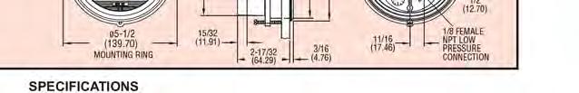
16 bearing surface for tubes to avoid abrasion during expansion and contraction. Flexible connectors shall not be required FILTERS A. Furnish combination filter section with 2-inch pleated MERV 8 flat pre-filter with microbial resistant Intersept coating and 19-inch final filter. Provide side loading and removal of filters. B. Filter media shall be UL 900 listed, Class I or Class II. C. Filter Magnehelic gauge(s) shall be furnished and mounted by others ADDITIONAL SECTIONS A. Plenum section shall be provided and properly sized for inlet and/or discharge air flow (between 600 and 1500 feet per minute). The plenum shall provide single or multiple openings as shown on drawings and project schedule. B. Access section shall be provided for access between components. Floor options shall include.125-inch aluminum treadplate or drainpan as shown on project schedule. C. Mixing box section shall be provided withtop outside air opening and right side return air opening with or without parallel low leak airfoil damper blades. Dampers shall be hollow core galvanized steel airfoil blades, fully gasketed and have continuous vinyl seals between damper blades in a galvanized steel frame. Dampers shall have stainless steel jamb seals along end of dampers. Linkage and ABS plastic end caps shall be provided when return and outside air dampers sized for full airflow. Return and outside air dampers of different sizes must be driven separately. Damper Leakage: Leakage rate shall be less than two tenths of one percent leakage at 2 inches static pressure differential. Leakage rate tested in accordance with AMCA Standard 500. PART 3: EXECUTION 3.01 INSTALLATION A. Install in accordance with manufacturer s Installation & Maintenance instructions ENVIRONMENTAL REQUIREMENTS A. Do not operate units for any purpose, temporary or permanent, until ductwork is clean, filters are in place, bearings lubricated, and fan has been test run under observation EXTRA MATERIALS A. Provide [one, two, etc.] extra set(s) [fan belts, filters, etc.] for each unit as shown on project schedule.


17 ARI Certified Ratings integral face & bypass coils
.")


18 coil construction (horizontal tubes) Damper Actuator Aeromix dampers are actuated manually, electrically or pneumatically (shown). Equipped with automatic temperature control, the actuator will self-adjust as needed to deliver the preset temperature on the leaving air side of the coil. Headers & Connections Aeromix headers are fabricated from carbon steel pipe. Non-ferrous, stainless steel and copper-nickel are available options. Male pipe thread connections are standard. Flanged and butt-weld connections are available options. Casing Aeromix coil casings are made of heavy gauge galvanized steel. Stainless steel and aluminum casings are available options. The tube sheets are punched and embossed to provide tube support and to minimize tube wear. Perimeter casing mounting holes are available upon request. PAGE 4


19 coil construction (horizontal tubes) Finned Tubes Aeromix coils feature aluminum star patterned plate fins for maximum heat transfer. The fins are attached to the tubes by mechanical expansion of the tubes, ensuring a permanent fin-to-tube bond. Full fin collars allow for both precise fin spacing and maximum fin-to-tube contact. The tubes are 5/8" od x.035" heavy wall seamless copper and are brazed to carbon steel headers. Stainless steel, carbon steel and copper-nickel tubes are available options. Dampers Aeromix dampers are made of heavy gauge galvanized steel and feature a unique shape which blends the air over the finned tube and bypass zones without changing the air pressure drop. This produces even, tempered air on the downstream side of the coil. Stainless steel and aluminum dampers are available options. Linkages Aeromix damper linkages are simple and reliable in design, ensuring accurate adjustment and long life. Control linkages are built from common parts, and the compact arrangement keeps overall length to a minimum. PAGE 5
20 design features Non-freeze Construction Aeromix coils for both steam and hot fluids are designed to provide freeze protection. Because the leaving air temperature from the Aeromix is controlled by dampening of the airflow, modulation of the steam or fluid is unnecessary. This feature maintains adequate steam pressure or tube velocity and prevents freeze-up. In addition, the vertical tube Aeromix steam coil is designed with tubewithin-a-tube construction. Steam enters the coil through the inner tube and protects the condensate from freezing as it condenses in the outer tube. The Aeromix for both steam and hot fluids provides the most reliable freeze protection available. Free Thermal Movement of Heating Elements Aeromix coils with vertical tubes have individually finned tubes which allow each tube to expand and contract independently. The headers are secured to the casing with free thermal movement of the tube bundle provided through embossed holes in the top casing opposite the header end. With fixed headers and free thermal movement of the tubes, strain on the tube joints is eliminated, and the tube bundle is isolated from the supply and return piping. Accurate Temperature Control Aeromix heating coils maintain a preset air temperature by heating a portion of a cold air stream and bypassing the remainder. The heated and bypassed air mix at the discharge of the coil to produce the desired temperature. Built-in face and bypass dampers mix hot and cold air streams in response to a thermostat downstream of the coil. As the entering air temperature changes, the dampers adjust to maintain the preset leaving temperature (from bypass fully closed for maximum heat output, to bypass fully open for minimum heat output) without the need to modulate the heating medium. Response to the thermostat is immediate and effective, even when minimum temperature rise is needed. Even Air Temperature Aeromix coils have adjacent heating and bypass sections to produce an evenly distributed air temperature across the leaving face of the coil. The air will mix within 3 feet downstream of the coil, allowing a maximum variance in air temperature of 5 degrees F. Minimum Temperature Override Aeromix dampers position to full bypass and completely close off the heating elements when the entering air temperature equals the leaving air temperature set point. With the air stream diverted around the heating elements, temperature override is minimized. Constant Air Volume Aeromix coils maintain a constant pressure drop as they operate due to the design of the dampers and bypass sections. This unique feature allows for constant air volume regardless of the position of the dampers. Controls Aeromix damper actuators may be pneumatic or electric, controlled by a thermostat downstream of the coil. Aerofin can supply actuators and thermostats, or the installer may provide his own. With loss of control air, pneumatic actuators fail with dampers fully open (zero bypass) for full heating operation. As an option, pneumatic actuators can be provided that fail with dampers fully closed (100% bypass). Variety of Heating Media Aeromix coils can be used with a variety of heating media. Hot water, hot ethylene glycol solution and steam are typical. Also available are applications with special heat transfer fluids such as alcohol-based fluids, organic high-temperature fluids and petroleum-based hot oils. Consult Aerofin for performance ratings for your specific application and conditions of service. PAGE 6


21 Full Heat At full load conditions, the dampers of the Aeromix are fully open, blocking the bypass sections of the coil. All air flows across the finned tube sections, allowing maximum heat transfer and temperature rise. temperature control Modulated Heat As the entering air temperature rises, the dampers begin to close, allowing a portion of the air to flow through the bypass sections. The coil operates at a reduced load, and the air mixes downstream of the coil to maintain the desired leaving air temperature. Full Bypass When the entering air temperature reaches the desired leaving air temperature, the dampers close completely, forcing all of the air through the bypass sections. The finned tube sections are isolated, and air temperature override is minimized. PAGE 7
22 Dry aeromix coil weights (pounds) for 1-0 through 5-0 FL - horizontal tubes FL TF ROWS weight and face area charts (horizontal tubes) NOTE: Weight table based on 10 FPI aluminum Aeromix face area (sq. ft.) for 1-0 through 5-0 FL - horizontal tubes FL TF PAGE 11
 PAGE")
23 water or steam aeromix (horizontal tubes) PAGE 14
24 Piping Information 1. Full sized condensate piping should be maintained from the coil to the steam trap. The pipe size should not be reduced at the coil. 2. Thermostatic traps should be used for venting only. Float & thermostatic traps, or bucket traps, should be used for condensate removal. The trap size should be selected using the pressure differential between the steam supply and condensate return mains degree check valves should be used because they open with a lower head of water. 45 degree check valves should not be used. 4. Condensate drips should be piped into the return main downstream of the steam trap. 5. Ensure that the steam control valve is properly sized. 6. A pump & receiver tank, or a steam pump, should be installed between steam traps and overhead condensate return mains. Condensate should not be lifted to an overhead main using only the steam pressure. 7. Strainers should be used on the steam supply side of the coil to collect any scale or debris. 3/32 inch mesh is recommended. 8. All coils should be provided with proper air vents to eliminate noncondensable gases. 9. All coils should be provided with the proper vacuum breakers. 10. Piping mains should be supported independently of the coils. Do not use the Aeromix coil to support any piping. piping information PAGE 15
25 handling, storage, installation, operation & maintenance Handling/Storage Each vertical tube Aeromix coil is provided with two eyebolts for lifting. A spreader bar should be used to produce a vertical lift. Horizontal tube Aeromix coils can be lifted and handled using conventional rigging (straps, slings, etc.). Special lifting provisions can be provided upon request. If the coil is to be stored prior to installation, place it in a dry and protected area. Installation General/Arrangement The finned tube core of the coil is firmly supported within the casing, with the tubes capable of thermal expansion through the casing. No adjustment of the header is required. Level installation is necessary to ensure proper drainage. Provide a 36" minimum space downstream of the coil for adequate mixing of bypassed and heated air. Support Support the coil by resting the bottom of the casing directly on the floor or other support structure, or by bolting the casing perimeter face flange to the air duct or wall. Do not support the air duct system with the casing of the Aeromix coil. Vertical tube coils may stand on support legs to provide clearance above the floor for installation of supply and return piping. Piping Supply and return piping should be supported independently of the coil. Do not use the coil as a an anchor for the piping system Refer to page 15 for Aerofin s recommended piping installation. Controls The required leaving air temperature from the coil is maintained by automatic positioning of the face and bypass dampers via an electric or pneumatic actuator, in response to a thermostat downstream of the coil. The averaging type temperature sensing element should be placed perpendicular to the tubes and across all face and bypass sections, not closer than 36 from the leaving air side of the coil. Mount the actuator onto the damper operator assembly. Mounting holes may be drilled as necessary to accommodate attachment hardware. Follow the control manufacturer s instructions for interfacing of the electric or pneumatic actuator to the air thermostat. A factory supplied pneumatic operator will position the dampers for full heating (fail with bypass closed, face open) upon loss of air pressure, unless ordered with reverse operation. An electric actuator will remain in the last operating position upon loss of power. Operation Pre-Start-Up Assure that the damper operator moves the dampers to fully close the face and reverses to fully close the bypass. Set the thermostat so that the face opens and the bypass closes when heat is required. Start-Up On start-up, the steam or water supply should be fully on before starting the air flow. Allow time for all air to be fully purged from the system and for the heating surface to fully heat up to avoid heating lag. Preheating a cold system will avoid excessive steam condensate loading and freeze-up at the PAGE 16
26 start of a steam heating system. After preheating, fully open the dampers for full face exposure (by-pass closed) and start the air flow. Set the thermostat for the desired air temperature. Shut-Down On shut-down, stop the air flow before turning off the steam or hot water supply. This procedure is imperative when the coil is heating subfreezing air. With the air flow shut off, leave the steam or hot water supply full on if the coil remains undrained and exposed to subfreezing air temperatures. Drain the coil free of water/condensate as soon as possible. Water left standing in the system may result in freeze damage. Venting Steam coils must have a provision for venting non-condensable gases (air and carbon dioxide) which are relieved from condensing steam. Build up of non-condensable gases will reduce the coil s heating capacity and can cause corrosion of the system. Provide venting as shown on page 15. Vacuum Breaker Use a vacuum breaker on steam heating coils as shown in the piping diagrams. This provision is essential for drainage of condensate should the coil be exposed to a vacuum condition relative to the pressure in the condensate return main, particularly upon shut-down when the supply steam is turned off. Modulation Steam: The supply steam pressure may be modulated for reduced heating capacity during the warmer portion of the heating season if desired. The coil features inner distributing tubes (nonfreeze construction) for uniform, even heating under low thermal loading. Hot Water: The supply water temperature may be modulated for reduced heating capacity if a temperature sensing element is used in the return piping and set to sustain a leaving water temperature not less than 100 F. Maintenance Periodic inspection is recommended for continued performance of the coil. Accumulation of dust, lint, oil, etc. will cause clogging and fouling of the fin surface and damper operation. Check for worn and loose parts and smooth damper operation. The fin surface may be cleaned with a noncorrosive solvent, compressed air and/or steam. Avoid direct high pressure blast to the fins. When cleaning with solvent, neutralize per the manufacturer s instructions and rinse with tap water. Strainers, drip legs, dirt pockets and steam traps in the piping system should be inspected and cleaned periodically. handling, storage, installation, operation & maintenance PAGE 17


27


28


29


30


31

32 TEFC Super-E Premium Efficient Motors efficiency in your choice of steel-band or cast iron frame, ideal for tough industrial applications. The TEFC enclosure protects the motor from harsh environments because air does not pass freely through the motor. An external shaft-driven fan circulates air over the frame housing. Class F insulation, a 1.15 Service Factor and Exxon Polyrex EM grease are some of these motors standard features. Super-E motors have an insulation system that meets the requirements of NEMA MG1 Part for VFD use and are considered (with or without base). TEFC - Totally Enclosed Fan Cooled Foot Mounted, 230/460, 460 & 575 Volts, Three Phase, 1/2-200 Hp Hp kw RPM Frame Catalog No. High V Full Load Locked Rotor Full Load Torque Lb. Ft. Efficiency % Power Factor % Bearings 1/2 3/4 Full Load 1/2 3/4 Full Load 230/460 & 460 Volts 1/ EM E CD EM F CD EM E CD T EM3546T E CD T EM3581T E CD EM E CD T EM3556T E CD T EM3582T E CD / EM E CD / T EM3550T E CD / T EM3583T E CD / EM E CD / T EM3554T E CD / T EM3584T E CD / T EM3607T E CD / T EM3667T E CD EM E CD T EM3555T E CD T EM3586T E CD EM E 14.1 CD T EM3558T E CD T EM3587T E CD T EM3614T E CD T EM3664T F CD T EM3559T E CD T EM3610T E CD T EM3660T E CD T EM3611T E CD T EM3661T E CD T EM3704T E CD T EM3764T E CD T EM3613T E CD T EM3663T E CD T EM3615T E CD T EM3665T E CD T EM3708T E CD T EM3768T E CD DE ODE Volt Code C Dim. Conn. Diag. No. Notes NOTE: Volt Code: E = /460V, 60Hz; E1 = 230/460V, 60Hz, usable at 208V; F = 230/460V, 60 Hz See page 68 for Layout drawing. See page 93 for Connection Diagrams. Efficiencies shown are nominal. Data subject to change without notice. Contact Baldor for certified data. Shaded ratings are cast iron frames. 7


33 Protecting VFD-Driven Motors In: HVAC Systems The Greening of America s Buildings The growing green movement has led to a flood of new standards including the US Greens Building Councils Building Performance Initiative, the Green Building Initiative, and LEED all aimed at increasing energy efficiency and sustainability. Challenged to reduce energy consumption and to document savings, America s facilities managers are installing variable frequency drives (VFDs) in HVAC systems as one of the best ways of achieving such savings. The Promise of VFDs VFDs reduce energy consumption by allowing motors to run less than full speed. When used to control air conditioning, air handling, or pump motors, VFDs can yield energy savings of 20 ~ 30% or more by allowing motors to run at reduced speeds to compensate for changes in load. The Need for Shaft Grounding on VFD-Driven Motors Applications: Rooftop systems But, VFDs can damage the motors they control. They induce currents on motor shafts that discharge through the bearings, causing pitting, fluting, and catastrophic motor failure. Without bearing protection, any savings from the use of VFDs can be quickly wiped out by the cost of replacing motors and by system downtime. To make HVAC systems sustainable as well as energy efficient, a reliable method of bearing protection is required. Indoor or outdoor air handling units Proven, Long-Term Bearing Protection Chilled water pumps By diverting bearing currents safely to ground, AEGIS SGR Shaft Grounding Rings ensure the reliable, long-term operation of VFDdriven motor systems, locking in energy savings and making these systems truly sustainable and truly green! Ventilation fans Fan walls Air or water cooled chillers Condensing fans E l e c t r o S t a t i c Te c h n o l o g y w w w. e s t - a e g i s. c o m
34
1.1 This section applies to air handling units for HVAC Systems.
 AIR HANDLING UNITS GENERAL INFORMATION 1.1 This section applies to air handling units for HVAC Systems. DESIGN REQUIREMENTS 2.1 Design Criteria a. The decision to use modular central station air handling
Brown University Revised August 3, 2012 Facilities Design & Construction Standards SECTION AIR HANDLING UNITS
 SECTION 23 70 00 AIR HANDLING UNITS PART 1. GENERAL 1.1 Section includes air-handling units to 15,000 cfm and accessories. 1.2 Related Sections 1 : A. Division 01 - Brown University Standard for Narragansett
UNIVERSITY OF MISSOURI Central Station Air-Handling Units March
 GENERAL: 1. This section provides criteria for the design and installation of air handling units. DESIGN GUIDELINES: Design General 1. Location 1.1. For new construction, and existing buildings where possible,
SECTION AIR HANDLING UNIT
 SECTION 15800 - AIR HANDLING UNIT PART 1 - GENERAL 1.01 RELATED DOCUMENTS A. Basic Requirements: Provisions of Section 15010, BASIC MECHANICAL REQUIREMENTS, and Section 15030, ELECTRICAL REQUIREMENTS FOR
Guide Spec Summary. Option List. Date: 05/21/2001. EarthWise Modular Climate Changer Full Spec. Prepared by: Phone Number: Prepared for:
 Date: 05/21/2001 Time: 08:50:16 AM Job Name: EarthWise Modular Climate Changer Full Spec Location: Any Town, Earth Prepared by: Phone Number: Prepared for: Guide Spec Summary Option List SUBMITTALS Submittals
AIR HANDLERS. Central Station (CS3) Roof Mounted (RT) (Modular AL Frame AHU)
 Roof Mounted (RT) (Modular AL Frame AHU)") AIR HANDLERS Central Station (CS3) (Modular AL Frame AHU) Roof Mounted (RT) CONTENTS 1. CS3 Modular Aluminium Frame AHU : Unit Types 2. Casing Structure 3. Blowers and Drives 4. Coils 5. Options and Accessory
AIR HANDLERS Central Station (CS3) (Modular AL Frame AHU) Roof Mounted (RT) CONTENTS 1. CS3 Modular Aluminium Frame AHU : Unit Types 2. Casing Structure 3. Blowers and Drives 4. Coils 5. Options and Accessory
SECTION AIR COILS
 PART 1 - GENERAL 1.1 RELATED DOCUMENTS A. Drawings and general provisions of the Contract, including General and Supplementary Conditions and Specification Sections, apply to this Section. B. Related Sections:
A. Air Handling Units shall be designed to the specific requirements of the application: Recirculation or 100% Makeup.
 SECTION 23 70 00- CENTRAL HVAC EQUIPMENT PART 1: GENERAL 1.1 PURPOSE: A. This standard is intended to provide useful information to the Professional Service Provider (PSP) to establish a basis of design.
A. Section includes Factory Packaged, Modular units, providing cooling and heating for air distribution systems.
 15855 AIR HANDLING UNITS SPECIFIER: CSI MasterFormat 2004 number: 237313 PART 1 GENERAL 1.1 SUMMARY A. Section includes Factory Packaged, Modular units, providing cooling and heating for air distribution
AIR HANDLING UNITS Vibration Isolation Air Filtration Equipment Ductwork.
 SECTION 15855 AIR HANDLING UNITS PART 1 GENERAL 1.01 SUMMARY A. Related Sections: 1. 15240 - Vibration Isolation. 2. 15885 - Air Filtration Equipment. 3. 15890 - Ductwork. 1.02 REFERENCES A. Air Moving
KINGS COUNTY JAIL EXPANSION PHASE III COUNTY OF KINGS SECTION
 SECTION 237433, PART 1 - GENERAL 1.1 RELATED DOCUMENTS A. Drawings and general provisions of the Contract, including General and Supplementary Conditions and Division 01 Specification Sections, apply to
A. American National Standards Institute (ANSI) : Establishes requirements applicable to certifying direct gas-fired heaters.
 : Establishes requirements applicable to certifying direct gas-fired heaters.") Section 15 _ Energy Recovery Air Handling System Part 1: GENERAL 1.1 Section Includes: A. Energy Recovery Air Handler B. Controls (most by Others) C. Equipment Schedule 1.2 Related Sections: A. Section
Section 15 _ Energy Recovery Air Handling System Part 1: GENERAL 1.1 Section Includes: A. Energy Recovery Air Handler B. Controls (most by Others) C. Equipment Schedule 1.2 Related Sections: A. Section
TYPICAL CPA SPECIFICATIONS
 TYPICAL CPA SPECIFICATIONS 4/10/2017 UNIT CONSTRUCTION: Casing: The exterior casing of the unit shall be constructed of 18-gauge, G235 galvanized steel (optional stainless steel or aluminum), unpainted.
Modular Supply Make-Up Air Unit
 Modular Supply Make-Up Air Unit Model MSX Flexible Design Factory Assembled Heating Options Hot Water Steam Electric Cooling Options Evaporative Direct Expansion Chilled Water November 2009 Product Features
SECTION PACKAGED ROOFTOP AIR CONDITIONING UNITS - CUSTOM
 SECTION 23 81 06 - PACKAGED ROOFTOP AIR CONDITIONING UNITS - CUSTOM PART 1 - GENERAL 1.1 SUMMARY A. This Section includes equipment types that contain all the components of the refrigeration process within
High Plume Blowers Suggested Specification Section (Master Format 1996) Suggested Specification Section (Master Format 2004)
 Suggested Specification Section (Master Format 2004)") High Plume Blowers Suggested Specification Section 15500 (Master Format 1996) Suggested Specification Section 23 38 16 (Master Format 2004) PART 1 GENERAL 1.01 WORK INCLUDED High Plume Laboratory Exhaust
High Plume Blowers Suggested Specification Section 15500 (Master Format 1996) Suggested Specification Section 23 38 16 (Master Format 2004) PART 1 GENERAL 1.01 WORK INCLUDED High Plume Laboratory Exhaust
SPECIFICATION DELETED SECTION CENTRIFUGAL HVAC FANS
 SECTION 23 34 16 CENTRIFUGAL HVAC FANS PART 1 - GENERAL 1.01 RELATED DOCUMENT A. Drawings and general provisions of the contract, including General and Special Conditions and Division 01 Specification
SECTION CONVECTION HEATING AND COOLING UNITS
 PART 1 GENERAL 1.01 SECTION INCLUDES A. Baseboard radiation. B. Finned tube radiation. C. Convectors. D. Unit heaters. E. Cabinet unit heaters. F. Fan-coil units. G. Unit ventilators. H. Blower-coil units.
SECTION AIR COILS
 PART 1 - GENERAL 1.1 DESCRIPTION SECTION 23 82 16 AIR COILS SPEC WRITER NOTE: Delete between //---// if not applicable to project. Also delete any other item or paragraph not applicable in the section
Submittal Data Performance Data Electrical Data
 ERMS Series Submittal Data Submittal Data Unit Designation: Job name: Architect: Engineer: Contractor: Performance Data Revision: 07/01/11 Cooling Capacity: EER: Heating Capacity: COP: Ambient Air Temp:
DARTMOUTH COLLEGE DESIGN January 3, 2012 & CONSTRUCTION GUIDELINES
 SECTION 15856 MODULAR AIR HANDLING UNITS PART 1 DESIGN DIRECTIVES 1.1 QUALITY ASSURANCE A. NFPA Compliance: Modular air handling units and components shall be designed, fabricated, and installed in compliance
Direct Fired Heater Model AD Specification
 Direct Fired Heater Model AD Specification Description A Direct-fired gas heating and ventilating unit(s), as indicated on the drawings shall be furnished. Unit(s) shall be tested in accordance with ANSI
Internal ridged board 1" x 1.5 foil face installation shall be installed on roof, walls and base of casing.
 A-D WITH MPU SPECIFICATION WRITTEN SPECIFICATION Description A Modular Packaged Heating, Cooling and ventilating unit(s), as indicated on the drawings shall be furnished. Direct Fired Gas Unit(s) shall
Submittal Transmittal
 Submittal Transmittal Standard St. Joe's - Sonntag Pavillion St. Joseph s Hospital 350 W. Thomas Road Phoenix, AZ 85013 Project # 5690A Tel: Fax: Kitchell Contractors Inc of AZ Date: 9/16/2011 Reference
University of Delaware
 University Contact: Energy & Engineering Group (302) 831-1744 SECTION 23 73 00_AIR HANDLING UNITS PART 1 GENERAL 1.1 SUMMARY A. Section Includes: 1. Modular custom & semi-custom built indoor air handling
SAS Steadyair Make-Up Air Units Technical Guide
 TGSAS-3 SAS Steadyair Make-Up Air Units Technical Guide A COMPLETE AIR TEMPERING PACKAGE FOR COMMERCIAL, INSTITUTIONAL, AND INDUSTRIAL APPLICATIONS S ince 1875, the L.J. Wing Company has been a leader
Chilled Water DOAS Fan Powered Terminal Units
 Chilled Water DOAS Fan Powered Terminal Units CHILLED WATER DOAS FAN POWERED TERMINAL UNITS DOAS TERMINAL UNITS FEATURES AND BENEFITS MINIMUM VENTILATION CONTROL The DOAS unit provides the Designer, Owner
WE ARE PLEASED TO PROVIDE THE ENCLOSED SUBMITTAL FOR YOUR REVIEW AND APPROVAL
 PREPARED FOR: DATE: JOB NAME: WE ARE PLEASED TO PROVIDE THE ENCLOSED SUBMITTAL FOR YOUR REVIEW AND APPROVAL EQUIPMENT DETAILS ITEM TAG DESCRIPTION MODEL NUMBER 1 2 3 4 5 6 7 8 9 10 11 12 13 14 15 EQUIPMENT
EHH SERIES DRAW THROUGH FAN COILS CFM
 EHH SERIES DRAW THROUGH FAN COILS 400-5000 CFM TABLE OF CONTENTS TABLE OF CONTENTS 2 INTRODUCTION 3 GUIDE SPECIFICATIONS 4 UNIT OVERVIEW 6 TECHNICAL DATA 8 DIMENSIONS 10 COMPUTER SELECTION 11 GEMCOOL PROFILE
Catalog Destiny Indoor Air Handler. Models Horizontal Configuration. Vertical Configuration
 Destiny Indoor Air Handler Models 002 030 Catalog 580-8 Horizontal Configuration Vertical Configuration Table of Contents Introduction.... 2 Certification...2 Smoke Control and Management Systems...2 Features
SECTION PACKAGED ROOFTOP AIR CONDITIONING UNITS
 SECTION 15732 - PACKAGED ROOFTOP AIR CONDITIONING UNITS PART 1 - GENERAL 1.1 SECTION INCLUDES A. Package roof top unit. B. Heat exchanger. C. Refrigeration components. D. Unit operating controls. E. Roof
FAS Fresh Air Supply Units
 TGFAS-2 FAS Fresh Air Supply Units TECHNICAL GUIDE STEAM AND HOT WATER MAKE-UP AIR HEATERS WITH INTEGRAL FACE AND BYPASS COILS FOR EFFECTIVE TEMPERATURE CONTROL Since 1875, the L.J. Wing Company has been
Bulletin C6200 MAY Buffalo. Big Buffalo. Air Handling. Custom Applications
 Bulletin C6200 MAY 20 3 Buffalo Air Handling Big Buffalo Custom Applications Buffalo Air Handling Big Buffalo The historic strength of Buffalo Air Handling is the custom designed air handling equipment
Project Manual. MAHG PROJECT No February 21, architecture planning interiors. Equipment Package
 Project Manual architecture planning interiors 6400 Riley Park Drive Fort Smith, Arkansas 72916 O: 479.782.1051 F: 479.782.6019 e: info@mahgarch.com MAHG AR CHITE NO. C-93 2.21.2018 ARKAN CTUR AS E REGISTERED
Product Specifications. Vertical Floor Consoles By First Co.
 NOW WITH 18 GAUGE CABINET AND FACTORY INSTALLED SERVICE SWITCH Product Specifications VFB Series VSB Series VCB Series Vertical Console Fan Coils 300-00 CFM Vertical Floor Consoles By First Co. VFB Series
AIR HANDLER SPECIFICATION
 AIR HANDLER SPECIFICATION Air Handlers AH-1 through 5 The following air handlers will be supplied: AH-1 FX15-4842 Series 5700 CFM AH-2 FX15-4236 Series 3990 CFM AH-3 FX15-3633 Series 2570 CFM AH-4 FX15-3330
FCC Fan-Coil Units High-Performance, Vertical
 FCC Fan-Coil s High-Performance, Vertical Model FCC construction features Piping and supply-duct connections are from top of unit, eliminating the need for side or back access Right or left-hand configurations
SSL & SBS Engineering Guide
 REDUCED-FOOTPRINT VERTICAL BLOWER COIL UNITS SSL & SBS Engineering Guide SO TOUGH, WE GUARANTEE IT. SSL SBS Table of Contents Features and Benefits... 3 Construction Features... 4 Features and Options...
B. Unit construction shall comply with ASHRAE 15 Safety Code, NEC, and ASME applicable codes (U.S.A. codes).
.") Guide Specifications PART 1 GENERAL 1.01 SYSTEM DESCRIPTION Microprocessor controlled, air-cooled liquid chiller utilizing scroll compressors, low sound fans, hydronic pump system and optional fluid storage
Guide Specifications PART 1 GENERAL 1.01 SYSTEM DESCRIPTION Microprocessor controlled, air-cooled liquid chiller utilizing scroll compressors, low sound fans, hydronic pump system and optional fluid storage
K*ES120 DESCRIPTION TECHNICAL GUIDE SPLIT-SYSTEM EVAPORATOR BLOWERS 10 NOMINAL TONS EER 8.5 ACCESSORIES FIELD INSTALLED TABLE 1: ARI RATINGS*
 TECHNICAL GUIDE SPLIT-SYSTEM EVAPORATOR BLOWERS K*ES120 10 NOMINAL TONS EER 8.5 DESCRIPTION These completely assembled dual circuit evaporator blower units include a well-insulated cabinet, a DX cooling
A. Codes and Standards that are Standard at the University:
 PART 1: GENERAL 1.01 Purpose: 1.02 References: 1.03 Requirements: A. This standard is intended to provide useful information to the Professional Service Provider (PSP) to establish a basis of design. The
SECTION AIR DUCT ACCESSORIES
 SECTION 23 33 00 AIR DUCT ACCESSORIES PART 1 - GENERAL 1.1 SUMMARY A. Section includes back-draft dampers, combination fire-and-smoke dampers, duct access doors, fire dampers, smoke dampers, volume control
Indirect Gas-Fired Make-Up Air
 Indirect Gas-Fired Make-Up Air Model IG 800 to 7,000 cfm Up to 400,000 Btu/hr Multiple Furnace Control Options Optional Evaporative Cooling May 20041 Product Features Model IG Indirect Gas-Fired Make-Up
UNIVERSITY SERVICES ANNEX James Madison University Harrisonburg, Virginia State Project Code: Architect s Project Number:
 SECTION 233423 - HVAC POWER VENTILATORS PART 1 - GENERAL 1.1 RELATED DOCUMENTS A. Provisions of the Contract and of the Contract Documents apply to this Section. 1.2 PERFORMANCE REQUIREMENTS A. Operating
UNIVERSITY OF ROCHESTER DESIGN STANDARDS NOVEMBER 1, 2013
 SECTION 15800 - AIR HANDLING EQUIPMENT 1.1 GENERAL A. All air handlers installed shall conform to the University of Rochester specification Guideline for Semi-Custom and Pre-Engineered Air Handling Units.
DIVISION 15 MECHANICAL
 DIVISION 15 MECHANICAL A. GENERAL DESIGN CONDITIONS 1. Design occupied spaces to maintain 72 F and a space dew point temperature not to exceed 55 F. 2. Design classroom and office space buildings with
1.03 RELATED SECTIONS: The following sections contain requirements that relate to this section.
 SECTION 15855 GAS FURNACE/DX COOLING UNIT PART 1 - GENERAL 1.01 RELATED DOCUMENTS A. Drawings and general provisions of contract including General and Supplementary Conditions of Division 1 of Specification
SeasonMaker ThinLine Fan-coil Units
 Catalog C: 720-12 SeasonMaker ThinLine Fan-coil Units Type TSH & TSC Horizontal Design TSS, TPF, TSF & TSB Vertical Design C L I S T E D Ratings Certified by the Air Conditioning & Refrigeration Institute
Construction Standards Page Exclusively published and distributed by Architectural Computer Services, Inc. (ARCOM) for the AIA
 for the AIA") Construction Standards Page 233423-1 Copyright 2009 by The American Institute of Architects (AIA) Exclusively published and distributed by Architectural Computer Services, Inc. (ARCOM) for the AIA Modified
Construction Standards Page 233423-1 Copyright 2009 by The American Institute of Architects (AIA) Exclusively published and distributed by Architectural Computer Services, Inc. (ARCOM) for the AIA Modified
Complete HVAC Capability. Central Station Air Handling Units. Publication No. WT-CSX-0616A
 Publication No. WT-CSX-0616A Central Station Air Handling Units Complete HVAC Capability Horizontal Draw-Thru to Size 65 Vertical Draw-Thru to Size 50 1000 to 60,000 CFM Forward Curved or Airfoil Wheels
LETTER OF TRANSMITTAL
 LETTER OF TRANSMITTAL FRANK A. ANZALONE Date: FAA Job No. 157 GENERAL CONTRACTOR Attention: Mr. Brent Guilbeau - Coleman Partners 1401 Derek Drive, Suite B Hammond, LA 70403 3377 North Boulevard Phone:
SSL / SBS Sales Guide BLOWER-COILS REDUCED-FOOTPRINT, VERTICAL
 SO TOUGH, WE GUARANTEE IT. SSL / SBS Sales Guide BLOWER-COILS REDUCED-FOOTPRINT, VERTICAL SSL SBS www.superiorrex.com SSL / SBS Series: BIG ON FEATURES; SMALL IN SIZE Contractors All SSL/SBS model blower-coil
C13-Series Engineering Guide
 Engineering Guide Effective January 2018 Horizontal Air-Cooled, Water-Cooled, Chilled Water and Heat Pump Contents Product Features............................... 3 Product Options................................
PRODUCT CATALOG BLOWER COILS.
 2016 PRODUCT CATALOG BLOWER COILS www.superiorrex.com SBH / SBV Series Design Features DESIGNED FOR MAXIMUM FLEXIBILITY Both Horizontal and Vertical Belt Drive Blower Coils are designed to maximize flexibility
EMBASSY SERIES SINGLE PACKAGE AIR CONDITIONERS (WATER-COOLED) C2ED060, 090, 120 & 180 5, 7-1/2, 10 & 15 Nominal Tons
 C2ED060, 090, 120 & 180 5, 7-1/2, 10 & 15 Nominal Tons") 560.20-TG1Y (388) EMBASSY SERIES SINGLE PACKAGE AIR CONDITIONERS (WATER-COOLED) C2ED060, 090, 120 & 180 5, 7-1/2, 10 & 15 Nominal Tons Each circuit includes a fully hermetic compressor with a crankcase
560.20-TG1Y (388) EMBASSY SERIES SINGLE PACKAGE AIR CONDITIONERS (WATER-COOLED) C2ED060, 090, 120 & 180 5, 7-1/2, 10 & 15 Nominal Tons Each circuit includes a fully hermetic compressor with a crankcase
MAC-120HE-03 Air-Cooled Chiller
 MAC-120HE-03 Air-Cooled Chiller 10 Ton / 120,000 BTUH Air-Cooled Chiller 380/415/460-3-50/60 1 HVAC Guide Specifications Air-Cooled Liquid Chiller Nominal Size: 10 Tons Multiaqua Model Number: MAC-120HE-03
Vision and Skyline Semi-custom Air Handlers
 Vision and Skyline Semi-custom Air Handlers Flexible design solutions to match building applications Skyline Outdoor Air Handler 900 to 65,000 cfm Vision Indoor Air Handler 900 to 100,000 cfm Custom solutions
SPLIT-SYSTEM EVAPORATOR BLOWERS K2EU060, K4EU090, K3EU120 & K1EU180 5 Thru 15 Nominal Tons DESCRIPTION ACCESSORIES FIELD INSTALLED
 (491) SPLIT-SYSTEM EVAPORATOR BLOWERS K2EU060, K4EU, K3EU & K1EU180 5 Thru 15 Nominal Tons DESCRIPTION These completely assembled units include a well-insulated cabinet, a DX cooling coil with copper tubes
Modular Heating & Ventilating Unit Model IGX-HV
 Modular Heating & Ventilating Unit Model IGX-HV Indirect Gas-Fired Heating Evaporative Chilled Water DX Cooling October 2008 Product Features Model IGX-HV Indirect Gas-Fired Heating and Ventilating Unit
MACH N-407 Heat Pump Air-Cooled Chiller
 MACH060-01-N-407 Heat Pump Air-Cooled Chiller Heat Pump Air-Cooled Chillers for Global Residential and Light Commercial Microclimates MACH NOMENCLATURE BREAKDOWN MACH-060-01 - N - 407 Refrigerant Type
ENGINEERING GUIDE. Water-Cooled Self-Contained Units C-Series, Vertical
 ENGINEERING GUIDE Water-Cooled Self-Contained Units C-Series, Vertical TABLE OF CONTENTS Introduction...2 Product Overview...3 Nomenclature...4 General Data...5 Cooling Performance Data....6 Evaporator
Direct Gas-Fired Make-Up Air
 Direct Gas-Fired Make-Up Air Model TSU Heavy Duty, High Airflow Applications Manufacturing and Industrial Facilities Up to 64,000 cfm August 2012 Products Model TSU Direct Gas-Fired Make-Up Air Unit The
SeasonMaker ThinLine Fan-coil Units
 Catalog C: 720-12 SeasonMaker ThinLine Fan-coil Units Type TSH & TSC Horizontal Design TSS, TPF, TSF & TSB Vertical Design C L I S T E D Ratings Certified by the Air Conditioning & Refrigeration Institute
Warm. IFR Indirect Fired Gas Heating Systems. Applied Air. Keeps You
 TGIFR IFR Indirect Fired Gas Heating Systems Technical Guide for: Outdoor Rooftop Mounted Units To 46,000 CFM And 4,000 MBH Output Applied Air Keeps You Warm Indirect Fired Heating Systems Technical Guide
SECTION FAN COIL UNITS
 PART 1 GENERAL 1.1 RELATED DOCUMENTS A. Drawings and general provisions of the Contract, including General and Supplementary Conditions and Specification Sections, apply to this Section. B. Related Sections:
MAC N-407 Air-Cooled Chiller
 MAC036-01-N-407 Air-Cooled Chiller Air-Cooled Chillers for Global Residential and Light Commercial MicroClimates MAC036 NOMENCLATURE BREAKDOWN MAC036-01 - N - 407 Refrigerant Type Air-Cooled Chiller 036=
SECTION (15833) - HVAC POWER VENTILATORS
 - HVAC POWER VENTILATORS") PART 1 GENERAL 1.01 SUMMARY SECTION 23 34 23 (15833) - HVAC POWER VENTILATORS A. Section Includes: 1. Centrifugal Roof Ventilators. 2. Up-blast Roof Exhaust Fans (Kitchen Hood Exhaust). 3. Ceiling-Mounted
PART 1 GENERAL 1.01 SUMMARY SECTION 23 34 23 (15833) - HVAC POWER VENTILATORS A. Section Includes: 1. Centrifugal Roof Ventilators. 2. Up-blast Roof Exhaust Fans (Kitchen Hood Exhaust). 3. Ceiling-Mounted
CS 2. Central Station Air Handlers Double Wall & Single Wall Installation, Operation & Maintenance Manual. Form No. 6120A
 CS 2 Central Station Air Handlers Double Wall & Single Wall Installation, Operation & Maintenance Manual Form No. 6120A TABLE OF CONTENTS Page Inspection... 2 Shipment of Units... 2 Handling... 2 Installation...
C. ASME Compliance: Fabricate and label water chiller heat exchangers to comply with ASME Boiler and Pressure Vessel Code: Section VIII, Division 1.
 SECTION 236426 - ROTARY-SCREW WATER CHILLERS PART 1 - GENERAL 1.1 SUMMARY A. This Section includes packaged, water cooled or air cooled as scheduled, electric-motor-driven, rotary-screw water chillers
SECTION COMPRESSED AIR SYSTEM. A. Pipe and pipe fittings, including valves, unions and couplings.
 SECTION 15481 COMPRESSED AIR SYSTEM PART 1 - GENERAL 1.1 SECTION INCLUDES A. Pipe and pipe fittings, including valves, unions and couplings. B. Air compressor. C. After cooler. D. Refrigerated air dryer.
engineering guide FH Fan-Coil Units Low-Profile, Horizontal
 engineering guide FH Fan-Coil Units Low-Profile, Horizontal FORM 115.26-EG7 (908) Table of contents FH Fan-Coil Units Low-Profile, Horizontal Features and Benefits... Construction Features... Standard
CAT-SIUH-2000(3) SUPERSEDES CAT-SIUH-98(2) SARAVEL INDUSTRIAL UNIT HEATERS
 SUPERSEDES CAT-SIUH-98(2) SARAVEL INDUSTRIAL UNIT HEATERS") CAT-SIUH-2000(3) SUPERSEDES CAT-SIUH-98(2) SARAVEL INDUSTRIAL UNIT HEATERS TABLE OF CONTENTS Introduction...3 Selection & Application.....4 Selection Examples......5-6 Ratings......7-8 Correction Factors......9-10
CAT-SIUH-2000(3) SUPERSEDES CAT-SIUH-98(2) SARAVEL INDUSTRIAL UNIT HEATERS TABLE OF CONTENTS Introduction...3 Selection & Application.....4 Selection Examples......5-6 Ratings......7-8 Correction Factors......9-10
SECTION PACKAGED, OUTDOOR, CENTRAL-STATION AIR-HANDLING UNITS
 SECTION 237413 - PACKAGED, OUTDOOR, CENTRAL-STATION AIR-HANDLING UNITS PART 1 - GENERAL 1.1 SUMMARY A. This Section includes packaged, outdoor, central-station air-handling units (rooftop units) with the
LGH/LCH WARNING. CAUTION Danger of sharp metallic edges. Can cause injury. Take care when servicing unit to avoid accidental contact with sharp edges.
 Service Literature The LGH/LCH high and standard efficiency 5, 0, 5 and 50 ton (, 0.7, 58. and 75.9 kw) units, are configure to order units (CTO) with a wide selection of factory installed options. The
SECTION AIR HANDLING UNITS WITH COILS. 1. Central Station Air Handling Units. 1. Section Basic Mechanical Requirements.
 SECTION 15855 AIR HANDLING UNITS WITH COILS PART 1 - GENERAL 1.01 SUMMARY A. Section Includes: 1. Central Station Air Handling Units. B. Related Sections: 1.02 REFERENCES 1. Section 15010 - Basic Mechanical
Large Capacity Fan Coil Units Catalog Belt-Drive and Direct-Drive Cabinet and Hideaway Models
 Large Capacity Fan Coil Units Catalog 735-12 Belt-Drive and Direct-Drive Cabinet and Hideaway Models Table of Contents Agency Listing and Nomenclature... 3 Overview....................................
MAC-036HE-02-L High Efficiency Air-Cooled Chiller Air-Cooled Chillers for Global Residential and Light Commercial Micro Climates Rev 1.
 MAC-036HE-02-L High Efficiency Air-Cooled Chiller Air-Cooled Chillers for Global Residential and Light Commercial Micro Climates Rev 1.1 HVAC Guide Specifications Air-Cooled Liquid Chiller with Low Ambient
MAC-048HE-01-L High Efficiency Air-Cooled Chiller Air-Cooled Chillers for Global Residential and Light Commercial Micro Climates Rev 1.
 MAC-048HE-01-L High Efficiency Air-Cooled Chiller Air-Cooled Chillers for Global Residential and Light Commercial Micro Climates Rev 1.1 HVAC Guide Specifications Air-Cooled Liquid Chiller with Low Ambient
Guide Spec Summary. Option List. Date: 05/21/2001. EarthWise T-Series AHU Full Spec. Prepared by: Phone Number: Prepared for: Acceptable Manufacturers
 Date: 05/21/2001 Time: 08:53:15 AM Job Name: EarthWise T-Series AHU Full Spec Location: Any Town, Earth Prepared by: Phone Number: Prepared for: Guide Spec Summary Option List Bid Type Acceptable Manufacturers
VIFB Coil Technical Guide
 TGVIFB-4 VIFB Coil Technical Guide VERTICAL TUBE INTEGRAL FACE AND BY-PASS HEATING COILS FOR PREHEATING Since 1875, the L.J. Wing Company has been a leader in providing innovative solutions for diffi cult
A. Section includes split-system air-conditioning units consisting of separate evaporator-fan and compressor-condenser components.
 Page 238126-1 SECTION 238126 - This Section includes requirements for the LEED Rating System. However, equipment specified in this Section may not qualify for LEED Rating System prerequisites and credits.
PhiloWilke Partnership Addendum No. 2 A/E Project No April 2016
 SECTION 23 21 23 PART 1 - GENERAL 1.01 RELATED DOCUMENTS A. Drawings and general provisions of the Contract, including General Conditions and Division 01 Specification Sections, apply to this Section.
MAC-060HE-01-L High Efficiency Air-Cooled Chiller Air-Cooled Chillers for Global Residential and Light Commercial Micro Climates Rev 1.
 MAC-060HE-01-L High Efficiency Air-Cooled Chiller Air-Cooled Chillers for Global Residential and Light Commercial Micro Climates Rev 1.2 HVAC Guide Specifications Air-Cooled Liquid Chiller with Low Ambient
40 RM/RMS Packaged Air-Handling Units
 ConcepcionCarrier Air conditioning Company Philippines 40 RM/RMS 008034 Packaged AirHandling Units INSTALLATION MANUAL, STARTUP & SERVICE INSTRUCTIONS Contents Page Page Safety Considerations 1 40RM Physical
Hood Depot Internatioonal, Inc., Phone S. Powerline Road, Deerfield Beach, FL
 The Kitchen Cool by Hood Depot is a conditioned make up air unit design with flexibility, form and function kept in mind. Our unit offers a variety of configurations that allow the customer to customize
SPLIT-SYSTEM EVAPORATOR BLOWER DESCRIPTION FEATURES L4EU NOMINAL TONS
 036-21096-001 (0101) SPLIT-SYSTEM EVAPORATOR BLOWER L4EU240 20 NOMINAL TONS DESCRIPTION This 20 ton evaporator blower is designed with two distinct modules to provide maximum application flexibility. The
Cabinet Unit Heaters Steam / Hot Water
 11-160.4 February, 2005 Cabinet Unit Heaters Steam / Hot Water Model C MODEL IDENTIFICATION Table of Contents I. Model Identification... 3 Page Il. IIl. III. IV. Design Benefits A. Features and Benefits...
T-SERIES SPLIT SYSTEM UNITS R-410A - 60 HZ. EER up to to 20 Tons Cooling Capacity - 71,000 to 236,000 Btuh AIR CONDITIONERS TS
 PRODUCT SPECIFICATIONS CONDITIONERS TS T-SERIES SPLIT SYSTEM UNITS R-410A - 60 HZ Bulletin No. TSA-072-240 (11/2016) 072-090 Models 180-240 Models 120-150 Models EER up to 11.7 6 to 20 Tons Cooling Capacity
Submittal Data PERFORMANCE DATA CERTIFIED DIMENSION PRINTS CERTIFIED ROOF CURB DIMENSION PRINTS SERVICE OPTION DIMENSION PRINTS
 AutoZone R Model Single Package Rooftop Gas Heating/Electric Cooling Unit Size 07 with Puronr (R---410A) Refrigerant Submittal Data PERFORMANCE DATA CERTIFIED DIMENSION PRINTS CERTIFIED ROOF CURB DIMENSION
VariCool VAV Engineering Guide
 Engineering Guide Effective September 2017 Water-Cooled and Chilled Water, Variable Air Volume Contents Product Features... 3 UNIT FEATURES... 3 Product Features... 4 Marvel Plus Microprocessor Control
AIR HANDLER DESIGN WORK SHEET
 AIR HANDLER DESIGN WORK SHEET JOB Project: Date Representative Unit Model No. of Units Unit Tag(s) UNIT CONSTRUCTION UNIT ARRANGEMENT: [ HORIZ VERT] [ INDOOR OUTDOOR] [ BASE MTD CEILING HUNG CURB MTD]
MHNCCX DX with Hot Water Heat Ceiling Concealed 4-Pipe Heat / Cool Fan Coil 12,000-36,000 BTUH
 MHNCCX DX with Hot Water Heat Ceiling Concealed 4-Pipe Heat / Cool Fan Coil 12,000-36,000 BTUH 318 MHNCCX NOMENCLATURE BREAKDOWN 4-Pipe Heat/Cool Ceiling Concealed Fan Coil MHNCCW- XX - XX Ceiling Concealed
SECTION CUSTOM INDOOR CENTRAL-STATION AIR-HANDLING UNITS For large systems, 50,000 cfm or more.
 Page 237323-1 SECTION 237323 - For large systems, 50,000 cfm or more. PART 1 - GENERAL 1.1 RELATED DOCUMENTS A. Drawings and general provisions of the Contract, including General and Supplementary Conditions
TECHNICAL GUIDE DESCRIPTION SPLIT-SYSTEM AIR-COOLED CONDENSING UNITS MODELS: HF-07 FEATURES B-0703
 TECHNICAL GUIDE SPLIT-SYSTEM AIR-COOLED CONDENSING UNITS MODELS: HF-07 DESCRIPTION These Sunline 2000 units are completely assembled, piped and wired at the factory to provide one-piece shipment and rigging.
Series PACKAGED ROOFTOP UNITS, HEAT PUMPS AND OUTDOOR AIR HANDLING UNITS. Features:
 RZ PACKAGED ROOFTOP UNITS, HEAT PUMPS AND OUTDOOR AIR HANDLING UNITS Features: Air-cooled condenser, water-cooled condenser, or evaporative-cooled condenser packaged rooftop units from 55-240 tons Water-source
D. NEMA Compliance: Provide electric motors and components which comply with NEMA standards.
 PART 1: GENERAL 1.01 Purpose: A. This standard is intended to provide useful information to the Professional Service Provider (PSP) to establish a basis of design. The responsibility of the engineer is
SECTION CENTRAL HVAC EQUIPMENT
 SECTION 23 70 00 CENTRAL HVAC EQUIPMENT PART 1 - GENERAL 1.1 SUMMARY A. Packaged and Custom Air Handling Units 1.2 RELATED WORK A. Provide temporary heating, cooling, and ventilating as needed. 1.3 REFERENCES
Copyright 2003 and 2005 by The American Institute of Architects (AIA) Modified by MSU Physical Plant / Engineering and Architectural Services
 Modified by MSU Physical Plant / Engineering and Architectural Services") Page 238216-1 Copyright 2003 and 2005 by The American Institute of Architects (AIA) Exclusively published and distributed by Architectural Computer Services, Inc. (ARCOM) for the AIA Modified by MSU Physical
Page 238216-1 Copyright 2003 and 2005 by The American Institute of Architects (AIA) Exclusively published and distributed by Architectural Computer Services, Inc. (ARCOM) for the AIA Modified by MSU Physical
SECTION AIR COOLED WATER CHILLERS
 PART 1 GENERAL 1.1 SECTION INCLUDES A. Chiller package B. Charge of refrigerant and oil C. Controls and control connections D. Chilled water connections E. Starters F. Electrical power connections 1.2
Submittal Data PERFORMANCE DATA CERTIFIED DIMENSION PRINTS CERTIFIED ROOF CURB DIMENSION PRINTS SERVICE OPTION DIMENSION PRINTS
 Single Package Rooftop, High---Efficiency Heat Pump Units With Field---Installed Electric Heat Sizes 08 --- 14 with Puron R (R---410A) Refrigerant Submittal Data PERFORMANCE DATA CERTIFIED DIMENSION PRINTS