COMING SOON. New Generation DCC1000 Vari-Vac Control Center Energy Management System
|
|
|
- Jewel Patrick
- 6 years ago
- Views:
Transcription
 supplied to the building.")
1 COMING SOON New Generation DCC1000 Vari-Vac Control Center Energy Management System The Zone Valve Control Panel, DCC1000 provides differential vacuum modulating control of the Building s Steam Zone Valve to regulate the temperature of the building. To achieve regulated and controlled temperature, DCC1000 regulates the amount of heat (thermal energy) supplied to the building. The new DCC1000 is built around an innovative product line of programmable heating controllers, the PHC11 family. PHC11 is a programmable heating control which has the benefit of a dedicated, custom designed heating system functionality with programmability like a PLC system. DCC1000 is a standalone controller with the capability to interface with a local server, connect directly to intranet and/or internet, or a standalone controller to provide real time apartment temperature readings (in order to improve heating supply efficiency and avoid building/apartment overheating). The DCC1000 is designed to give maximum flexibility to heating system installers to tune performance by giving capability to program parameters. This gives varying capability to deal with errors in system components, curve compensation (weather patterns/characteristics) and heating system performance. Flexible Multiple Abilities For more information please contact GS Dunham LLC (718)
2 February 2007 BULLETIN C-5 PUMP SECTION Vacuum Pumps - Types VR, VRD, DV & DVD, Model C-5 APPLICATION The Vacuum Pump is the indispensable heart of the modern heating system. By rapidly exhausting air from the system it circulates steam quickly, minimizes the warm-up period and enables the heating system to function quietly. Types VR, VRD, DV, and DVD, Model C-5 Pumps, are designed for large and small projects with capacities of 5,000 through 65,000 EDR with discharge pressures of 20, 30, and 40 PSI. Each MEPCO duplex pump is equipped with its own automatic controls and so arranged to provide automatic standby service. It is not necessary for the operating engineer to switch from one condensate pump to the other manually, as the pumps alternate automatically on float control. If one float switch contact closes and for some reason that pump does not start, the other float switch contact will automatically close and start the other pump. Also, if the condensate load becomes too great for one pump, the other pump will start automatically. Both pumps then operate simultaneously. This feature is of great value to the operating engineer. CONSTRUCTION FEATURES THE CENTRIFUGAL PUMP. The bronze fitted Centrifugal Pump with its enclosed impeller is mounted in a straight line assembly directly connected to a heavy duty motor. It is designed to provide for hydraulic balance and to avoid steam binding under high water temperatures. THE EXHAUSTER. A jet-type exhauster of MEPCO design and manufacture is of the highest efficiency, based on over 60 years of successful design experience. ELECTRICAL CONTROLS. Furnished as standard are a float switch and a vacuum switch located in the accumulator portion of the tank, which brings on both vacuum pumps, speeding up the recovery time on this important function. A float control switch is located in the hurling portion of the tank to energize the condensate pump. The electrical controller is housed in a NEMA enclosure and includes a motor starter with overload circuit breaker and a three position selector switch for each pump. This device causes the pumps on duplex units to alternate in service yet permits one to follow the other into service if the first pump should fail to start. Also, if one pump cannot handle the condensate load, both pumps automatically operate simultaneously. RPM. Motor speeds for 60 cycle AC are O.D.P MEPCO reserves the right to make changes in specifications and design without notice.
3 DIMENSIONS AND SELECTION PUMP TAPPINGS IN INCHES DIMENSIONS IN INCHES PUMP EDR INLET VENT DISCHARGE A B C D E F G H I J K L M ½ 2 1¼ ¼ 61 15¼ 3¼ 1¾ ½ 1½ ½ / / ¾ 2¾ 3/8 15 Note: Without Isolation Valves deduct 6" from I dimension I G H J 37½ MAX VENT CONTROL PANEL LIFT RINGS VACUUM SWITCH GAUGE GLASS MECHANICAL ALTERNATOR K A B VACUUM GAUGE LOW WATER CUT OFF HIGH TEMPERATURE LIMIT SWITCH (OPTIONAL) FLOAT SWITCH C F THERMOMETER ISOLATION VALVES (OPTIONAL) D PRESSURE GAUGE M L CAPACITIES PUMP SIZE SQ. FT. RADIATION (EDR) 5,000 10,000 15,000 20,000 25,000 30,000 40,000 65,000 BOILER HORSE POWER BTU (MILLION) SIMULTANEOUS CAPACITY WATER GPM AIR CFM MOTOR HP AIR 3/ ½ # DISCH 1/2 1/2 3/4 3/ ½ 3 MOTOR HP WATER 30# DISCH 3/4 3/ ½ 1½ # DISCH 1 1 1½ 1½ 1½ ACCUMULATOR TANK GALLONS HURLING TANK GALLONS NOTES: 1) AIR AND WATER CAPACITIES ARE BASED ON 5½ HG 160 F. 2) RATINGS IN ACCORDANCE WITH VACUUM HEATING PUMP CODE OF THE ASHRAE.
4 TYPICAL SPECIFICATIONS VR, VRD = Simplex and Duplex Vacuum Pump DV, DVD = Simplex and Duplex Differential Vacuum Pumps 1. Provide simplex or duplex vacuum pump or differential vacuum pumps for operation with variable vacuum control system as herein specified. Quantities shall be as indicated on drawings. 2. Each vacuum pump shall be packaged type, simplex (2) pumps, duplex (4) pumps completely assembled, pre-piped and pre-wired. Materials and parts shall be of the highest quality. The condensate shall be discharged by a condensate pump and the air and gases shall be removed by a vacuum pump. The units shall include one or two condensate pumps and one or two vacuum pumps. Each packaged unit shall include a heavy copper-bearing steel condensate receiver, with a minimum 3/16" material thickness. The manufacturer shall provide stainless steel pressure gauges, water level gauge, stainless steel vacuum gauges, stainless steel dial thermometer, and check valves which have a stainless steel valve and seat. All gauges shall be observable from a single point located in the front of the unit. The tank shall be on rails to provide air space under the tank to allow for evaporation beneath the tank. The manufacturer shall provide lifting lugs on the unit for ease of installation. Companion flanges or unions shall be provided for all connections. 3. The condensate and vacuum pumps shall be centrifugal type, bronze fitted, with 250 F mechanical seals and dynamically balanced single cast bronze impellers. Motors shall be 3450 RPM and open drip proof type. Motor horsepower at design point and design voltage shall be adequate to handle load requirements, 208, 230, 460/3/ Provide each vacuum pump with a three position selector switch to permit automatic (float and vacuum) off and hand operation. When the selector switch is in the automatic position for the vacuum pumps, control shall be such that an increase in water level in the accumulator or a system call for vacuum will start both pumps. Provide each condensate pump with a three position selector switch to permit automatic (float only) off and test operation. A mechanical alternator shall provide for alternate operation of the condensate pumps, and for starting the standby pump, if the lead pump cannot handle the return condensate or if the lead pump fails to function. A low water condensate switch will break power to condensate pumps, in the event condensate recedes near suction opening of the vacuum pumps. Once water is restored to an acceptable level the pumps will return to normal operating condition. All liquid level switches shall be 4 bolt gasket type devices. 5. Provide a single consolidated control panel mounted and wired on the receiver. The control panel shall be mounted in an upright fashion with provision for removal to accommodate limited clearance entrance ways. The single control cabinet shall be NEMA 1. The panel shall incorporate the following: industrial grade motor protective circuit breakers (one for each motor), magnetic starters with overload protection, numbered terminal strip, and 3 position selector switches. The control circuit shall be protected by circuit breakers. The starters must be designed so as to limit contact bounce. The overloads shall provide single phase motor protection and shall be temperature compensated up to 40 C or 104 F. All electrical components shall have a verifiable life rating. All internal electrical components as well as the assembled and prewired control cabinet shall be UL approved. 6. Vacuum pump equipment is to be assembled, piped and valved in accordance with the manufacturers certified drawings. 7. Each pump shall have not less than the capacity of EDR, equivalent direct radiation indicated on the drawings. The water pumps shall be capable of simultaneously delivering the full rating in GPM and pressure as scheduled. Each air pump shall be capable of delivering the full rated air capacity specified. With both pumps operating, indicated air and water quantities shall be doubled. Quantities of water and air specified are at a temperature of 160 F and 5½" of vacuum. Each pump shall be rated in accordance with Vacuum Heating Pump Code of ASHRAE, and when exhausting against a closed suction, shall produce a minimum of 25" of mercury vacuum with water at 125 F. The receiving tank shall have a capacity as scheduled. The air removal tank shall have a capacity as recommended by the manufacturer and approved by the Engineer. 8. Each vacuum pump unit shall be tested at the plant of the manufacturer in accordance with the ASHRAE Standard Code for Testing and Rating Return Line Low Vacuum Heating Pumps. The manufacturer shall have been in design and manufacturing of vacuum systems for a minimum of 5 years. 9. The vacuum pump units shall be installed complete with all piping and new electrical wiring and connections. Overflow piping shall be directed to the nearest floor drain. 10. In the discharge line from each condensate pump the contractor shall provide a gate valve and a suitable spring loaded check valve. Near the inlet of the receiver for each vacuum pump unit the contractor shall provide a gate valve and strainer.
5 11. Differential Vacuum Pumps DV and DVD will require a Mepco differential controller installed near the end of the steam main farthest from the control valve, which shall be connected to both steam and return piping of the zone in which it is located. The differential controller shall maintain a positive pressure differential between steam and return piping by governing the differential vacuum pump operation. The differential controller shall operate on maximum 24 volt. 12. Available Options Positive seating suction isolation valves on both the condensate pumps and vacuum pumps NEMA 2, 3, 4, 4X, 12 Control Panel available 2 position selector switches High Temperature Limit Switch to disengage the vacuum switch if condensate reached 160 F. Fused disconnect switches 115 volt transformers Illuminated selector switches Liquid tight conduit Model C-5 Vacuum Pump The contractor shall furnish and install as specified in the plans and in accordance with the manufacturer s instructions (quantity) duplex MEPCO type (VR, VRD, DV, DVD) Vacuum Pump, which has a rating of 5, 10, 15, 20, 25, 30, 40, 65) square foot of Equivalent Direct Radiation and capable of discharging against (20, 30, 40) PSI pressure at the pump. Each pump shall be rated in accordance with the Vacuum Heating Pump Code of the ASHRAE and when exhausting against a closed orifice, shall produce a minimum of 25" of mercury vacuum with water 125 F. The pump shall be powered by volts, phase, hertz. The unit shall be factory wired and tested. VR - Standard Simplex Vacuum Pump OR DV - Differential Simplex Vacuum Pump 20 - System EDR (Air and Water Pump) EXAMPLE: Model Selection - VR - D C5 Duplex Configuration C-5 - Current Model Number 20 - Pump Discharge Pressure (psig) Job Name Location 1875 Dewey Avenue Benton Harbor, Michigan Phone Fax The specifications contained in this bulletin were effective at the time of publishing. We reserve the right to discontinue products at any time or to change specifications or design without incurring any obligation. For most current information, contact your Mepco representative.

6 FORM IO-RTMS VARI-VAC SECTION Type RTMS Control Valve BODY APPLICATION The MEPCO Control Valve (Type RTMS) is mounted in the zoned steam supply line as close to the main steam supply header as possible. It is used to control the amount of steam flowing into the zoned piping. It s opening and closing is controlled by the control center. It not only receives information, but also sends information to the control center indicating the degree that the valve is open, to allow the heat supply to be continuously controlled to exactly equal the heat losses through all extremes of weather. CAP SCREWS BELLOWS HOUSING CAP Type RTMS Control Valve CONSTRUCTION FEATURES RUGGED CONSTRUCTION Material: Valve Body Class 30 C.E. Inner Valve Naval Bronze Valve Seat Naval Bronze Configuration Valve Body Flanged 125# Ansi Inner Valve Ported Sleeve Type Single Seat through 3" Double Seat 4" through 10" UNIQUE DESIGN - Parabolic contour inner valve provides a linear curve when percent flow varies directly with percent of valve opening. IE: 40% open = 40% capacity. The ported sleeve inner valve provides a flexible throttling action from design demand through mild weather (low heat requirements.) FLEXIBILITY - The ported sleeve inner valve provides the throttling action through the full range of steam flow, particularly when the demand for heat is light and the rate of steam flow is small. CONTINUOUS FLOW - This throttling gives a continuous flow of steam and does not require periodic closing of the valve to prevent overheating in mild weather. VALVE POSITION INDICATOR - The inner valve lift from the seat, in percent of the maximum possible lift, is indicated by a pointer mounted on the linkage eccentric. RELIABILITY - The use of a bellows connection eliminates all packing around the stem and insures against air leakage when operating under a vacuum. VALVE OPERATION - The operator linkage is of the short coupled design. The eccentric is rotated by a low voltage reversing motor controlled from the Panel. Adjustable limit switches open the circuit when the motor has traveled to its limit in either direction.


7 INSTALLATION Install the Control Valve in an accessible location in the steam supply main in accordance with the typical installation details shown on reverse side or where shown on the plans or as directed. PIPING DETAILS - RTMS CONTROL VALVE If the location of the Control Valve will be such that the dial and pointer which indicates the percentage of valve opening cannot be easily seen from a convenient location, this can be easily corrected. To do so, remove the cap screws from the upper flange of the bellows housing and turn the lower valve assembly to any desired position within limits of the bolt holes. Allow the flange to drop away from the body of the valve only enough to allow clearance between the gasket and one of the castings after having separated the gasket from either of the casting. DO NOT ATTEMPT TO MAKE THIS CHANGE AT THE BELLOWS HOUSING CAP AS DAMAGE TO THE BELLOWS WILL RESULT. The protective covering shipped on the motor should not be removed until the electrician is ready to make the final wiring connections. *INLET/OUTLET VALVES MUST BE FLANGED GATE TYPE. FULLY LUGGED VALVES NOT RECOMMENDED. ROUGHING IN DIMENSIONS - RTMS CONTROL VALVE CONTROL CAPACITY SIZE OF DIMENSIONS IN INCHES VALVE SQ. FT. BYPASS SIZE IN. EDR* INCH A B C D E F G H 1-1/2 2, / / / /8 9-13/16 3-7/8 2 4, /4 8-3/8 4-3/ /8 23-1/ / /16 4-3/16 2-1/2 5, / /4 19-7/ / /2 9-13/16 4-1/2 3 9, /4 5-1/ / /16 7-1/2 5-1/8 9-13/16 5-1/8 4 13, / / / / / / , / / / /8 9-13/16 5-5/8 6 28, /4 8-1/8 22-5/8 30-3/ /4 9-13/ , /8 24-7/ / /2 10-3/8 9-13/16 8-5/ , /2 11-9/ /8 37-7/ / / /16 NOTE: If clearance beneath the valve is a problem and the valve cannot be installed with the motor beneath the steam main, it may be swung 180 degrees and installed with the motor above the steam main. The valve should not be installed in a horizontal or any other position off the vertical because of added wear on internal parts of the valve. The necessary dimensions for layout of this work are shown on reverse side of this page Dewey Avenue Benton Harbor, Michigan Phone Fax Form IO-RTMS Nov Printed in USA

8 Vent-Rite Manufacturer of MEPCO Pump Packages FORM M2137E VARI-VAC SECTION OUTDOOR SELECTOR, TYPE RTSO4100 APPLICATION The MEPCO RTSO 4100 Outdoor Sensor is factory built and tested, and is designed to determine the outdoor temperature and wind chill conditions for zoned heating systems governed by a Vari-Vac Heating Control System. It is composed of a temperature sensor(s) mounted in a weather resistant enclosure. The enclosure has screened louvered openings which permit passage of outside air to the sensor and averts insects and debris from affecting or damaging the sensor(s). This enclosure can be utilized for one to fifteen (1-15) zones. It is sold in single, two to ten (2-10) zone and eleven to fifteen (11-15) zone models. FEATURES The MEPCO RTSO Selector is basically a shielded resistance thermometer arranged for mounting outdoors. It consists of a temperature-sensitive winding encased in a weather tight enclosure; louvers in frame permitting access of outside air to the temperature-sensitive element, and weatherproof junction box with terminal for connection of electrical conductors. The aluminum frame has screened louver opening for excluding insects and is thermally insulated from the building. The RTSO 4100 Selector responds to the outdoor temperature and wind chill conditions. This enables the Temperature Control System to govern the supply of heat in accordance with these requirements. There is very little maintenance required by the Outdoor Sensor as it doesn't have any moving parts and the sensing elements are protected from debris by screened louvers. The Outdoor Sensor is available in three different enclosures which protect from one to fifteen sensors, thus providing one location to sample outside temperature for many zones of heating. The sensor(s) is designed to respond to the outdoor conditions of a building and provide this information to the various control centers. WHERE TO INSTALL: The RTSO Selector should be installed on an outdoor wall, located sufficiently high above the ground to be affected by the prevailing winter winds. The Selector should not, however, be located above the fifth floor of a multi-story building due to possible wide variations in temperature at high locations. It should also be located in areas where it will be shielded from the direct rays of the sun Dewey Avenue Benton Harbor, MI Phone Fax

9 TYPICAL INSTALLATION The MEPCO RTSO Selector is provided with four (4) 5/16" diameter holes for mounting (see roughing in and installation drawings, Form 3442) and may be mounted to masonry construction with lag screws. CONTROL CABLE SPECIFICATIONS All low voltage circuit wiring installed inside building or in conduit which will remain dry shall be a plastic jacketed cable or plastic insulated conductors. Each conductor is to be No. 18 AWG solid or stranded copper wire, covered with not less than 1/64" concetric wall of color coded plastic insulation. The conductors are to be formed into a uniformly round cable and covered with a concentric jacket of plastic that is not less than 3/64" thickness. This cable or lead covered control cable of similar internal contrusion may be used for underground conduit service. Cable conforming to these specifications is obtainable from MEPCO. Vent-Rite Manufacturer of MEPCO Pump Packages 1875 Dewey Avenue Benton Harbor, MI Phone Fax MEPCO reserves the right to make revisions to its products, their specifications, this file sheet and related information without notice. FORM M2137E PRINTED IN U.S.A.

10 Vent-Rite Manufacturer of MEPCO Pump Packages FORM M8160E OCTOBER 2009 VARI-VAC HEAT BALANCER Installation, Operation & Maintenance Manual 1875 Dewey Avenue Benton Harbor, MI Phone Fax
11 INTRODUCTION The MEPCO Pump Package Heat Balancer is the control convector. It is an important part of a Vari-Vac Heating Control System. It consists of a cabinet type convector with temperature sensitive resistance sensors mounted above and below the heating element. These sensors determine the rate of system heat out put, by measuring the inlet air temperature and outlet temperature. This data enables the control center to match the energy input to the heat loss. GENERAL This equipment is a factory built and tested Heat Balancer, designed for the purpose of determining the rate of heat input to a zoned heating system which is governed by a Vari-Vac heating control system. To assure satisfactory operation and to avoid costly damage to the unit, the following procedures should be observed. INDEX INSTALLATION Receiving Uncrating Location Mounting Piping Wiring OPERATION ADJUSTMENT MAINTENANCE REFERENCES For additional information concerning application of the Heat Balancer and Vari-Vac Heating Control Systems, contact your local MEPCO Pump Package representative.
12 INSTALLATION A. RECEIVING When the unit is delivered, an immediate visual inspection of the unit and its accessories should be made in the presence of the carrier s representative. If there is any evidence of rough handling or damage, a notation should be made on the delivery receipt. Shipping damages are the responsibility of the carrier and it is the obligation of the customer to file a claim. If requested, MEPCO Pump Packages will assist in the filing of the claim. B. UNCRATING When uncrating the Heat Balancer be sure that all temporary plugs remain in their tappings until you are ready to connect the unit to the system. Accompanying the balancer is a three quarter (¾) inch MEPCO Pump Packages RTD adjustable regulation fitting, and a one-half (½) inch IE-SW pattern MEPCO Pump Packages thermostatic radiator trap to connect the heat balancer to the steam supply and return piping. C. LOCATION The Heat Balancer must be located in an area representative of the zone served, where it will have circulation and be unaffected by strong air currents. Its location must be accessible and the surrounding air temperature must not average more that fifteen (15) degrees Fahrenheit from the normal room temperature. It should NOT be installed in a location where special adjustment of its steam supply is required for comfort, where its heat output is necessary for heating, or where it will be affected by external sources of heat, such as steam or return mains or the direct rays of the sun. If it must be mounted above steam or return mains, these mains must be covered with insulation. Corridors, basement rooms and stairwells may be suitable locations, but cold drafts from doors and windows should be avoided. A location for the Heat Balancer should be selected that will not require more than twenty (20) feet of horizontal piping between the steam main connection and the heat balancer, and where the heat balancer connection to the steam main will be at one quarter (¼) to one-half (½) the distance from the control valve to the end of the steam main, but not less that thirty (30) feet from the control valve. Consideration should also be given to the fact that a low voltage cable of 4- #18 wires must connect from the Heat Balancer to the control center. The minimum height at which the Heat Balancer should be mounted is four inches from the floor to the bottom of the Heat Balancer. 1
13 INSTALLATION CONTINUED D. MOUNTING To ensure proper flow of steam through the heating element, the Heat Balancer must be mounted exactly level. The Heat Balancer must be supported by the mounting lugs furnished for this purpose not by its piping connections. Wood screws are furnished to fasten the cabinet to the wall. When mounting the Heat Balancer, do no remove the cover from the unit unless it is absolutely necessary, as damage to the resistance coil may result. See Figure 1 for mounting dimensions. E. PIPING Connections from the steam and return main to the Heat Balancer must be made at the top of the mains to assure proper flow of steam and condensate. 1. Heat Balancer above the Steam Main (Figure 2). When the Heat Balancer is mounted above the steam main and return main the instructions should be observed: a. Grade the horizontal steam piping back toward the steam main with a downward slope of at least onehalf (½) inch per foot. b. If the horizontal distance between the point of take off from the steam main and the regulating fitting is eight (8) feet or less, the horizontal steam supply piping to the Heat Balancer should be one (1) inch nominal pipe. If the horizontal distance exceeds eight (8) feet the piping shall be one and one-quarter (1¼) inch nominal pipe. c. If the horizontal steam piping pitches toward the Heat Balancer, a drip trap must be installed in the piping before the regulating fitting. 2
14 INSTALLATION CONTINUED 2. Heat Balancer below the Steam Main (Figure 3): When the Heat Balancer is mounted below the steam main the following instructions must be observed a. Piping shall be made in accordance with that shown in Figure 3. b. Horizontal steam supply piping, if less that eight (8) feet in length, should be a nominal pipe size of one (1) inch. If greater that eight (8) feet, it should be a nominal pipe size of one and one-quarter (1¼) inches. c. Vertical piping connected to the horizontal supply piping should be threequarter (¾) inch nominal pipe size or larger. d. A MEPCO Pump Packages thermostatic radiator trap should be used to drip the down feed steam supply connection to the return main. CAUTION: Do not remove the cover of the Heat Balancer when making piping connections, to prevent damage to the temperature sensitive resistance coils. 3
15 INSTALLATION CONTINUED Union nuts and nipples have been installed at the factory. If it is necessary to remove them, exercise extreme care in order to prevent damage to the resistance coils and heating element. When installing union nuts and nipples, screw the regulating fitting nipple into the tapping marked in and the trap nipple into the tapping marked out. F. After the Heat Balancer has been properly located, installed and piped, conduit should be installed if necessary, and the unit wired. An electrical box is located on the side of the unit for easy access to terminal connections. To gain access to the terminal block, the electrical box cover plate must be removed. This can be accomplished by removal of the (2) two screws in the top of the cover plate. CAUTION: Do not damage the exposed resistance coils. It is recommended that MEPCO Pump Packages Control Cable #1804 be used to interconnect the Heat Balancer to the Control Center. Its wires are color coded RED, WHITE, BLUE, and GREEN to coincide with Vari-Vac wiring diagrams. When wiring the Heat Balancer, be sure that each wire is attached to its matched color coded terminal. The terminals are matched with the first letter of the color of the wire. Be sure that each connection is electrically and mechanically secure. If conduit is not used, strain relief bushings should be employed to anchor the cable firmly where it enters the unit This prevents strain on the electrical connections and eliminates abrading of the cable. When splicing the wires of the Heat Balancer to the cable, the splices must be in conformance with the latest revision of Form No and local standard practice. The Heat Balancer connections are listed in the table below. COLOR CODE AND TERMINAL CONNECTION - WIRING HEAT BALANCER TO CONTROL CENTER HEAT BALANCER TERMINAL CODE R W B G WIRE COLOR CODE CONNECTED TO WIRE COLOR CODE CONTROL CENTER TERMINAL NUMBER Red White Blue Green Control Center Control Center Control Center Control Center Red White Blue Green #11 #12 #13 #14 OPERATION The Vari-Vac Heat Balancer is a specialized convector which is connected between the steam main and the return main of its zone of operation. Its temperature sensitive resistance sensors determine the temperature of both the entering and leaving air, and furnishes this information to the Control Center. This information, along with information from other sensors sampling other temperatures within and without the zone, determines the amount of steam necessary to heat the zone to a predetermined temperature. The continual processing of information, from the Heat Balancer and other sensors, prevents over and under heating within the zone. OPERATION OF REGULATING FITTING The MEPCO Pump Packages RTD adjustable regulating fitting is shipped with the valve (½-¾) open, and must be installed in a vertical position. Do not seat the valve as the system should be allowed to operate for at least one week to clean out grease and other foreign matter before the regulation fitting is adjusted. When the system is put into operation, and during the control center adjustments, variations in the setting, between one (1) and three (3) turns open, may be required to balance the supply of steam to the Heat Balancer in relationship to the distribution of steam throughout the system. 4
 turns, until the Heat Balancer is emitting heat in relationship to the distribution of steam throughout the system.")
16 ADJUSTMENT To adjust the regulating fitting, remove the cap and insert a screwdriver into the slot in the fitting, turn it clockwise until the valve is seated, then turn it counterclockwise, usually one and one-half (1½) turns, until the Heat Balancer is emitting heat in relationship to the distribution of steam throughout the system. Be sure to replace the cap tightly on the fitting, to prevent tampering. MAINTENANCE At the beginning of the heating season, the heating element should be checked for accumulation of dust and lint and cleaned as necessary. The thermostatic trap should also be checked for proper operation and the RTD regulating fitting should be closed (clockwise rotation) and returned to the same number of turns open in order to clean the needle valve. 5
17

18
19
20
21
22
23

.")
24 Pressure Diaphragm Differential Switch Features High reliability Dual switching capability High accuracy Tamper-proof external adjustment NEMA 4 Applications Pump & compressor monitoring HVAC systems Engine monitoring Machine tools Hydraulic power units Filtration systems Metal working Utility & power generation Series DPD1T, DPD2T General Specifications* Electrical Characteristics: Accuracy: Switch: Type: Rating: Wetted Parts: Diaphragm: Seals: All models incorporate Underwriters Laboratories, Inc. and CSA Listed single pole double throw snap-action switching elements. ± 0.5% of the adjustable range SPDT snap action; single or dual circuit /250 VAC; VAC (Class A or H limit switch). Consult product configurator for ratings of optional limit switches PH stainless steel Viton Approvals/Listings: PED (European): Temperature Range: Operating: Adjustment Instructions: Pressure: Vacuum Differential: Options: Shipping Weight: Compliant to PED 97/23/EC -65 F to +165 F (-54 C to +74 C) Turn adjustment screw clockwise to decrease pressure difference; counterclockwise to increase pressure difference Turn adjustment screw counterclockwise to decrease vacuum difference; clockwise to increase vacuum difference -Factory pre-set -NEMA 4X enclosure Single & dual - approximate 3.50 lbs. Enclosure: Die-cast aluminum anodized Other Parts: Nickel plated aluminum 300 series stainless steel Electrical Connection: Screw terminals on covered terminal strip through 1/2 NPT conduit fitting Enclosure Ratings: NEMA 4 Pressure Connection: 1/8 NPT female high + low * See product configurator for additional options. Wiring Code Wiring Diagram (contact status at atmospheric pressure) NC C NO C NC NO 1
25 Diaphragm Differential Switch Series DPD1T, DPD2T Technical Drawing ADJUSTING SCREW, CIRCUIT #2 5/16 HEX, SLOTTED (REMOVED COVER TO ADJUST) 1-3/4 (44.4) 3-1/2 (88.9) C L OF HIGH & LOW PRESSURE PORTS LOW PRESSURE PORT 1-15/32 (37.3) Ø MOUNTING HOLE 2 PL GROUND SCREW HIGH PRESSURE PORT ADJUSTING SCREW, CIRCUIT #1 5/16 HEX, SLOTTED (REMOVED COVER TO ADJUST) 2-1/16 (52.4) 13/32 (10.3) 1-3/4 (44.4) 3-1/2 (88.9) 4-9/16 (115.9) 1-1/8 (28.6) 2-1/4 (57.2) /16 (46.0) 1-23/32 (43.7) 15/16 (23.8) 3-7/16 (87.3) 1/2 NPT CONDUIT CONNECTION 2-3/16 (55.6) 5-5/8 (143) 5-15/16 (151) 3/8 (9.5) Dimension in inches (mm) Product Configurator Example DPD1T -A 3SS H Hermetically sealed limit switch option - Class I, Division II (requires AA, CC or HH limit switch) Options Base Configuration DPD1T DPD2T Limit Switch 1 -A -B -H -J -M -GH -AA -CC -GH -HH Single setpoint housed Dual setpoint housed /250 VAC; VAC; (standard for pressure range 3SS, 80SS or 150SS) /250/480 VAC; VAC; VDC; VDC /250 VAC; VAC; (standard for pressure range 18SS) /250 VAC; VAC; (comes with an elastomer boot) /250 VAC; VAC; VDC; VDC VAC; with gold contacts Hermetically sealed; 4 125/250 VAC (not available on vacuum models) Hermetically sealed; /250 VAC (not available on vacuum models) Hermetically sealed; VAC with gold contacts (not available on vacuum models) Hermetically sealed; 5 125/250 VAC (not available on vacuum models) Adjustable Range Working Range Adjustable Range (PRESSURE) 3 Approx. Deadband 2 Decreasing - psi (bar) Increasing - psi (bar) (Actuation Value) Max. Diff. Pressure (Proof) psi (bar) Min Max Min Max psi (bar) psi (bar) 3SS (.00) 2.76 (.2).27 (.02) 3 (.2) ( ) 10 (.7) 18SS (.03) (1.2).72 (.05) 18 (1.2) ( ) 60 (4.1) 80SS (.03) 75.3 (5.2) 5.2 (.4) 80 (5.4) (.1 -.3) 160 (10.9) 150SS (.10) (9.7) 10.2 (.7) 150 (10.2) (.2 -.6) 300 (20.4) Working Range Adjustable Range (VACUUM) 4 Approx. Deadband 2 Decreasing (In. Hg) Increasing (In. Hg) (Actuation Value) Max. Diff. Pressure (Proof) In. Hg Min Max Min Max In. Hg In. Hg 3SS SS FX -L6 -CS -Sxxx NEMA 4X enclosure 6-contact terminal block (DPD2T only) CSA approved Factory preset (consult factory) NOTES: 1 Consult supplementary guide for specific deadband values 2 Deadband values indicated when used with the standard limit switch 3 Working range may be extended to 400 psi provided the maximum differential pressure (proof) is not exceeded 4 Working range may be extended to 30 in.hg provided the maximum differential pressure (proof) is not exceeded 3211 Fruitland Avenue Los Angeles, CA Fax: See Barksdale s Standard Conditions of Sale Specifications are subject to modification at any time Bulletin #S0083-B 09/ Printed in the U.S.A. 2

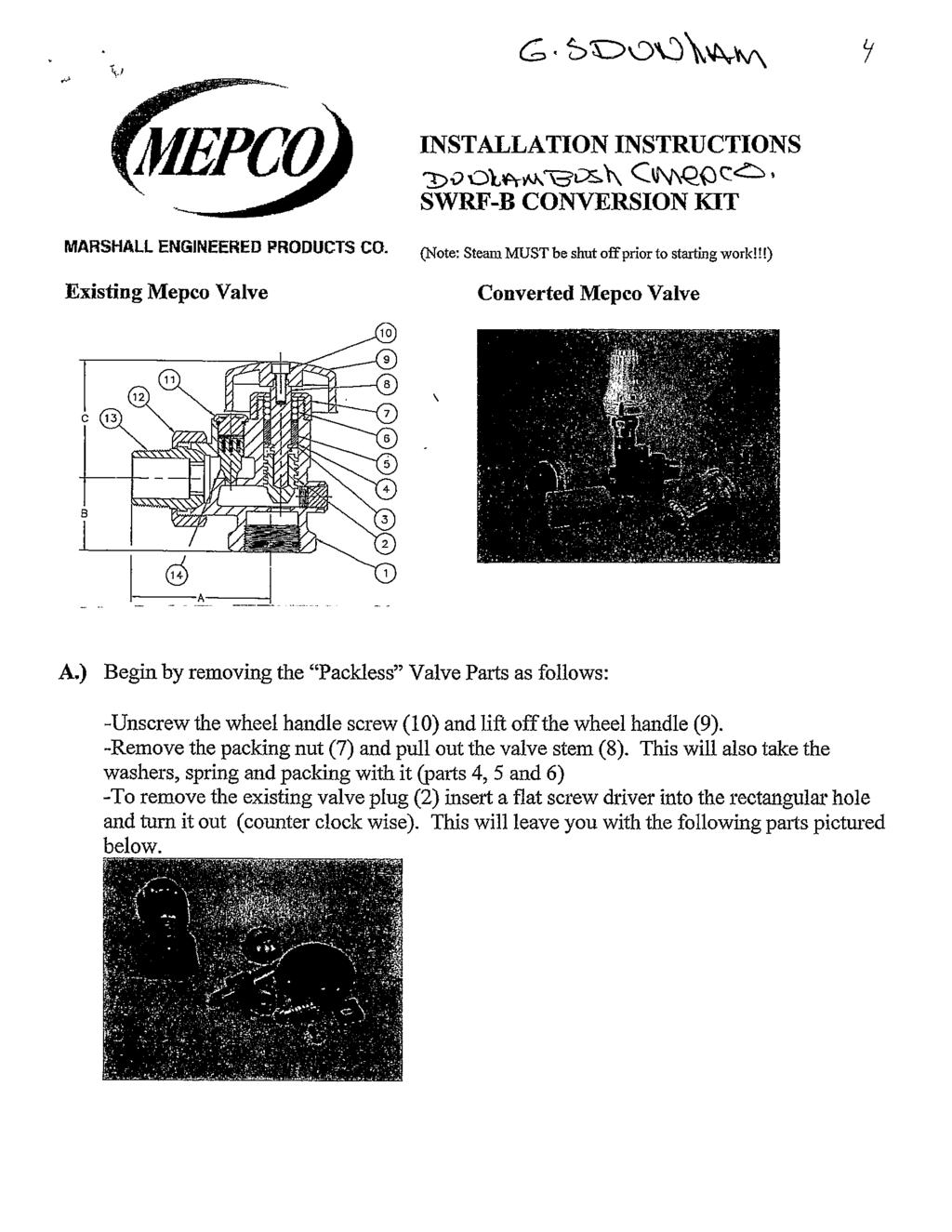
26 FORM 2147E MARSHALL ENGINEERED PRODUCTS CO. MEPCO REGULATING VALVE Regulating Valve - Spring Packed, Type SWRF, Model C APPLICATION
27 MARSHALL ENGINEERED PRODUCTS CO Walker Ridge Drive, Suite C, Grand Rapids, Michigan Phone Fax FORM 2147E PRINTED IN U.S.A.
28 FORM 2148 MARSHALL ENGINEERED PRODUCTS CO. Spring Packed, Type SWRF, Model B APPLICATION
29 FORM 2148 MARSHALL ENGINEERED PRODUCTS CO Walker Ridge Drive, Suite C, Grand Rapids, Michigan Phone Fax PRINTED IN U.S.A.
30
31
32 Thermostatic Radiator Valve MARSHALL ENGINEERED PRODUCTS CO. Actuators & Bodies Part Numbers Thermostatic Radiator Valve Bodies (THV) Straight Pattern Body (S) Item Number Size Model /2" 1/2" THVZST /4" 3/4" THVZST " 1" THVZST /4" 1-1/4" THVZST Thermostatic Radiator Valve Actuators (THV) Internal Sensor (I) Item Item No. Cap Model Liquid Element (LI) None THVLI Straight Pattern Body (S) Item Number Size Model /2" 1/2" THVZSS /4" 3/4" THVZSS Remote Bulb (R) Item Item No. Cap Model Liquid Element ' 6' THVLR " 1" THVZSS /4" 1-1/4" THVZSS Wall Mounted (LB) Angle Pattern Body(A) Item Number Size Model /2" 1/2" THVZAT /4" 3/4" THVZAT " 1" THVZAT /4" 1-1/4" THVZAT Item Item No. Cap Model ' 6' THVLB ' 16' THVLB ' 32' THVLB Angle Pattern Body(A) Item Number Size Model /2" 1/2" THVZAS /4" 3/4" THVZAS " 1" THVZAS /4" 1-1/4" THVZAS Wall Dual Capillary (LC) Item Item No. Cap Model ' 6' THVLC Reverse Angle Pattern (R) Item Number Size Model /2" 1/2" THVZRT /4" 3/4" THVZRT " 1" THVZRT Note: A complete thermostatic radiator valve includes a valve body and an actuator. Reverse Angle Pattern (R) Item Number Size Model /2" 1/2" THVZRS /4" 3/4" THVZRS " 1" THVZRS Angle Steam Vent Body (V) Item Number Size Model /8" 3/8" THVV Marshall Engineered Products Company Industry Leaders in the Design and Manufacture of Engineered Steam & Hydronic Solutions 3056 Walker Ridge Drive NW Suite C Grand Rapids, MI Tel: Fax: Mepco@mepcollc.com


33 DUNHAM-BUSH (MEPCO)


34


35


36 COMBO STAINLESS STEEL THERMOSTATIC DISC
 Pattern Similar Left - Right")

37 FIG. 3 RIGHT HAND PATTERN (RH) Left Hand (LH) Pattern Similar Left - Right Hand Combo (LR) Pattern (configurations: AP, SW, RH, LH, VST, LR or VS) MEPCO Type
Vent-Rite. Cast Iron And Steel Receivers. Simplex, Duplex, Triplex And Quadruplex Units. Pump Capacities To 150 GPM. Discharge Pressure To 75 PSI
 Vent-Rite BULLETIN VCRV AUGUST 0 GUARDIAN Plus Cast Iron And Steel Receivers Simplex, Duplex, Triplex And Quadruplex Units Pump Capacities To 0 GPM Discharge Pressure To 7 PSI 87 Dewey Avenue Benton Harbor,
SECTION STEAM CONDENSATE PUMPS
 SECTION 23 22 23 - STEAM CONDENSATE PUMPS PART I - GENERAL 1.1 SECTION INCLUDES A. Steam Condensate Return Units, Gravity Return Type 1. Receiver 2. Pumps 3. Control Panel 4. Accessories Note to PSC: Although
TECHNICAL. Series 18. Pump Packages
 TECHNICAL S Y S T E M S Series 18 Pump Packages Series 18 Pump Packages Standard Features Close-coupled, end-suction, centrifugal pumps Mounted and wired pump starters Hand-Off-Auto switch for each pump
Condensate Boiler Feed Water Make-Up
 1144 Utica Ave, Brooklyn, NY 1103 July 0 New Catalogue Release Bulletin 9C.01 Low Inlet Condensate Receiver (7 from floor) Close Grained Cast Iron Simplex and Duplex Design To 0,000 SQ-Ft EDR Pump Capacity
SECTION STEAM CONDENSATE PUMPS
 PART 1 - GENERAL 1.1 DESCRIPTION SECTION 23 22 23 STEAM CONDENSATE PUMPS SPEC WRITER NOTES: 1. Delete between // ---- // if not applicable to project. Also delete any other item or paragraph not applicable
Title: YALE OFFICE OF FACILITIES PROCEDURE MANUAL Chapter: 01 - Yale Design Standard Division: HVAC Standards
 Date Description of Change Pages / Sections Modified ID 6/15/16 Entire document - mgl44 PART 1 - INTRODUCTION 1.1 PURPOSE A. This section is intended to define the general installation and minimum product
BuildingName The Description of the Project P DOCUMENTS
 ARCHITECTURE, ENGINEERING AND CONSTRUCTION P00000000 0000 DOCUMENTS ARCHITECTURE & ENGINEERING 326 East Hoover, Mail Stop B Ann Arbor, MI 48109-1002 Phone: 734-764-3414 Fax: 734-936-3334 SPECIFICATION
LABORATORY AIR COMPRESSORS AND VACUUM PUMPING SYSTEMS
 SECTION 22 20 00 LABORATORY AIR COMPRESSORS AND VACUUM PUMPING SYSTEMS PART 1 - GENERAL 1.1 RELATED DOCUMENTS: A. The Conditions of the Contract and applicable requirements of Division 1, "General Requirements",
Electric Pumps. Introduction. W4100, W4200 & W4300 Condensate Pumps. Typical Condensate Pump Features
 Electric Pumps Introduction W4100, W4200 & W4300 Condensate Pumps Watson McDaniel s Condensate Return and Boiler Feed Pumps are equipped with Cast Iron bodies and Bronze Impellers. The pump receiver tanks
INSTRUMENTATION AND CONTROL DEVICES FOR HVAC
 PART 1 GENERAL 1.01 RELATED REQUIREMENTS SECTION 23 0913 INSTRUMENTATION AND CONTROL DEVICES FOR HVAC A. Section 26 2717 - Equipment Wiring: Electrical characteristics and wiring connections. 1.02 ADMINISTRATIVE
Design and Construction Standards SECTION PLUMBING EQUIPMENT
 SECTION 15450 PLUMBING EQUIPMENT PART 1 GENERAL 1.1 SECTION INCLUDES: A. Water heaters. B. Packaged water heating systems. C. Water storage tanks. D. Water softeners. E. Pumps. F. Circulators. 1.2 REFERENCES
Hoffman Specialty Pump Products
 Condensate Units Boiler Feed Units Vacuum Heating Units Hoffman Specialty Pump Products S-0692C INDEX Condensate Return Units Series WC Series WCS Series SCC Boiler Feed Units Stock Watchman Condensate
B. HI Compliance: Design, manufacture, and install pumps in accordance with HI "Hydraulic Institute Standards."
 PART 1: GENERAL 1.01 Purpose: A. This standard is intended to provide useful information to the Professional Service Provider (PSP) to establish a basis of design. The responsibility of the engineer is
5. CONDENSATE PUMPS/UNITS
 INDEX Condensate Systems/Pumps GENERAL INFORMATION BURKS PARTS I&O MANUALS. CONDENSATE PUMPS/UNITS PUMP TYPES: GV GV6 USA: (937) 778-8947 Canada: (90) 47-6223 International: (937) 61-398 A 7/1 Condensate
SECTION HEATING BOILER FEEDWATER EQUIPMENT
 SECTION 23 53 00 HEATING BOILER FEEDWATER EQUIPMENT PART 1 - GENERAL 1.1 SUMMARY A. Section includes boiler feedwater pumps, de-aerators, accessories, controls and tanks. 1.2 REFERENCES A. ASME (American
PHYSICAL FACILITIES Consultant s Handbook Specifications Division 21 Fire Suppression 3000 Fire Pumps
 Note: The A/E must choose all design values in brackets below before using in project specifications 1 General 1.1 Provide UL listed and FM approved fire pump complete with pump, driver, controller and
SECTION (15486) - FUEL-FIRED, DOMESTIC WATER HEATERS
 - FUEL-FIRED, DOMESTIC WATER HEATERS") SECTION 22 34 00 (15486) - FUEL-FIRED, DOMESTIC WATER HEATERS System shall provide a complete hot water return throughout the entire system with balancing (flow control) valves not less than 10 feet from
SECTION 22 34 00 (15486) - FUEL-FIRED, DOMESTIC WATER HEATERS System shall provide a complete hot water return throughout the entire system with balancing (flow control) valves not less than 10 feet from
Domestic Pump Condensate Transfer Equipment
 Bulletin S-944L Domestic Pump Condensate Transfer Equipment CONDENSATE RETURN UNITS BOILER FEED UNITS LOW NPSH PUMPS VACUUM HEATING UNITS INDUSTRIAL VACUUM UNITS www.domesticpump.com Condensate Return
Domestic. Pump Series CB and CBE Condensate Units SINGLE OR DUPLEX 1,000 THRU 140,000 SQ. FT. EDR-250 THRU 34,748 LB./HR.
 Cast Iron Receivers: For years of dependable service; warranted for 20 years from date of shipment against failure due to corrosion. Each Receiver comes standard with Inlet connection, an overflow and
SECTION PLUMBING EQUIPMENT
 PART 1 GENERAL 1.1 SECTION INCLUDES A. Water heaters B. Packaged water heating systems C. Water storage tanks D. Water softeners E. Pumps F. Circulators 1.2 REFERENCES SECTION 22 30 00 PLUMBING EQUIPMENT
Series 1140 and 1141 Temperature Regulators
 Hoffman Specialty Installation & Maintenance Instructions HS-504(E) Series 1140 and 1141 Temperature Regulators! CAUTION FOLLOW ALL INSTALLATION AND OPERATING INSTRUCTIONS. TURN OFF WATER OR STEAM BEFORE
Stainless Steel Condensate Return Units
 Stainless Steel Condensate Return Units Pressurized and Atmospheric Deaerators HIGH QUALITY STAINLESS STEEL EXCEPTIONAL VALUE, EXTRAORDINARY QUALITY industrialsteam.com Stainless Steel Condensate Return
C. ASME Compliance: Fabricate and label water chiller heat exchangers to comply with ASME Boiler and Pressure Vessel Code: Section VIII, Division 1.
 SECTION 236426 - ROTARY-SCREW WATER CHILLERS PART 1 - GENERAL 1.1 SUMMARY A. This Section includes packaged, water cooled or air cooled as scheduled, electric-motor-driven, rotary-screw water chillers
J120 STEAM BOOSTER INSTALLATION, OPERATION, AND SERVICE MANUAL J120 STEAM BOOSTER. J120 Steam Booster Manual D
 INSTALLATION, OPERATION, AND SERVICE MANUAL J120 STEAM BOOSTER J120 STEAM BOOSTER J120 Steam Booster Manual REVISION HISTORY Revision Letter Revision Date Made by Applicable ECNs Details A 10-27-04 CBW
D. NEMA Compliance: Provide electric motors and components which comply with NEMA standards.
 PART 1: GENERAL 1.01 Purpose: A. This standard is intended to provide useful information to the Professional Service Provider (PSP) to establish a basis of design. The responsibility of the engineer is
VSA SEWAGE PUMP. Capacities to 1600 gpm, Heads to 120, Horsepower range 3/4 thru 40, 3 thru 6 discharge, 1750 and 1150 operation.
 Brochure# 228E 122011 TYPE VSA SEWAGE PUMP Capacities to 100 gpm, Heads to 120, Horsepower range 3/ thru 0, 3 thru discharge, 1750 and 1150 operation. HIGHLIGHTS Wet-Pit Installations Pumps Suspend From
A. Operation and Maintenance Data: For pumps to include in emergency, operation, and maintenance manuals.
 SECTION 23 21 23 - HYDRONIC PUMPS PART 1 - GENERAL 1.1 RELATED DOCUMENTS A. Drawings and general provisions of the Contract, including General and Supplementary Conditions and Division 01 Specification
C. ASSE 1013: Performance Requirements for Reduced Pressure Principle Backflow Preventers.
 SECTION 22 10 00 PLUMBING PIPING AND PUMPS PART 1 - GENERAL 1.1 Purpose: A. This standard is intended to provide useful information to the Professional Service Provider (PSP) to establish a basis of design.
SECTION COMPRESSED AIR SYSTEM. A. Pipe and pipe fittings, including valves, unions and couplings.
 SECTION 15481 COMPRESSED AIR SYSTEM PART 1 - GENERAL 1.1 SECTION INCLUDES A. Pipe and pipe fittings, including valves, unions and couplings. B. Air compressor. C. After cooler. D. Refrigerated air dryer.
DENVER PUBLIC SCHOOLS DESIGN AND CONSTRUCTION STANDARDS This Standard is for guidance only. SECTION PUMPS
 PART 0 A/E INSTRUCTIONS 0.01 Design Requirements A. Pumping system design 1. A primary-secondary pumping system is preferred. Redundant pipes are required for chillers and boilers. 2. Select pumps to operate
Domestic Pump Series VCMD TM Combination Vacuum & Boiler Feed Unit
 Custom engineered units to maintain optimum boiler levels and system vacuum requirements Four styles to choose from to minimize floor space requirements Multi-jet vacuum pumps for quiet, dependable and
Owner s Manual Therma-Stor II Heat Recovery System
 PO Box 8680 Madison, WI 53708 TS-138C Revised 8/08 Owner s Manual Therma-Stor II Heat Recovery System Installation, Operation & Service Instructions Read and Save These Instructions Table Of Contents 1.
FUEL OIL DAY TANKS. SST Level Controller: UL 508 LISTED
 FUEL OIL DAY TANKS SST Series - Engineering Submittal SST Series - Advanced Line Day Tanks Construction: UL 142 aboveground steel tank all seam welded, square, atmospheric tank of heavy gauge steel with
SECTION PLUMBING EQUIPMENT Piping (Plumbing). 2. Division 16 - Electrical Wiring and Connections.
. 2. Division 16 - Electrical Wiring and Connections.") SECTION 15450 PLUMBING EQUIPMENT PART 1 GENERAL 1.01 SUMMARY A. Related Sections: 1. 15410 - Piping (Plumbing). 2. Division 16 - Electrical Wiring and Connections. 1.02 SUBMITTALS A. Submit properly identified
SECTION 15450 PLUMBING EQUIPMENT PART 1 GENERAL 1.01 SUMMARY A. Related Sections: 1. 15410 - Piping (Plumbing). 2. Division 16 - Electrical Wiring and Connections. 1.02 SUBMITTALS A. Submit properly identified
PhiloWilke Partnership Addendum No. 2 A/E Project No April 2016
 SECTION 23 21 23 PART 1 - GENERAL 1.01 RELATED DOCUMENTS A. Drawings and general provisions of the Contract, including General Conditions and Division 01 Specification Sections, apply to this Section.
OPERATING AND MAINTENANCE MANUAL FOR ELECTRIC STAINLESS STEEL HEATER FOR DEIONIZED (DI) WATER ELECTRIC HEATER COMPANY BASE MODEL D
 WATER ELECTRIC HEATER COMPANY BASE MODEL D") OPERATING AND MAINTENANCE MANUAL FOR ELECTRIC STAINLESS STEEL HEATER FOR DEIONIZED (DI) WATER ELECTRIC HEATER COMPANY BASE MODEL D HUBBELL ELECTRIC HEATER COMPANY P.O. BOX 288 STRATFORD, CT 06615 PHONE:
OPERATING AND MAINTENANCE MANUAL FOR ELECTRIC STAINLESS STEEL HEATER FOR DEIONIZED (DI) WATER ELECTRIC HEATER COMPANY BASE MODEL D HUBBELL ELECTRIC HEATER COMPANY P.O. BOX 288 STRATFORD, CT 06615 PHONE:
Revitalize Building Mechanical Systems (4619)
") SECTION 235216 FIRE-TUBE CONDENSING BOILERS PART 1 - GENERAL 1.1 RELATED DOCUMENTS A. Drawings and general provisions of the Contract, including General and Supplementary Conditions and Division 01 Specification
SECTION 235216 FIRE-TUBE CONDENSING BOILERS PART 1 - GENERAL 1.1 RELATED DOCUMENTS A. Drawings and general provisions of the Contract, including General and Supplementary Conditions and Division 01 Specification
Paragon. Induced Draft, Counter Flow Optional Accessories
 ANTIFREEZE PACKAGE / RESISTANCE HEATING OPTION The antifreeze package is supplied to provide protection against freezing of standing water in the cooling tower sump due to shutdown during winter operation.
TM Series. Induced Draft, Counter Flow Optional Accessories
 ANTIFREEZE PACKAGE / RESISTANCE HEATING OPTION The antifreeze package is supplied to provide protection against freezing of standing water in the cooling tower sump due to shutdown during winter operation.
SECTION PLUMBING EQUIPMENT
 PART 1 GENERAL 1.01 SECTION INCLUDES A. Water heaters. B. Packaged water heating systems. C. Domestic water heat exchangers. D. Water storage tanks. E. Water softeners. F. Reverse osmosis equipment. G.
.005 ATMOSPHERIC DEAERATOR
 .005 ATMOSPHERIC DEAERATOR OCTOBER 1, 2007 GENERAL DESCRIPTION The Sellers atmospheric.005 deaerators condition make-up water and condensate returns to convert them into more desirable boiler feedwater.
MODEL P. 2 ft. NPSH Cast Iron Bronze Fitted Low NPSH Centrifugal Pumps. BULLETIN 112 Revised 7/09. PH (Horizontal Flange Mounted)
") SHIPPENSBURG PUMP CO., INC. P.O. BOX 279, SHIPPENSBURG, PA 17257 PHONE 717-532-7321 FAX 717-532-7704 WWW.SHIPCOPUMPS.COM BULLETIN 112 Revised 7/09 PH (Horizontal Flange Mounted) MODEL P 2 ft. NPSH Cast
SHIPPENSBURG PUMP CO., INC. P.O. BOX 279, SHIPPENSBURG, PA 17257 PHONE 717-532-7321 FAX 717-532-7704 WWW.SHIPCOPUMPS.COM BULLETIN 112 Revised 7/09 PH (Horizontal Flange Mounted) MODEL P 2 ft. NPSH Cast
Series 4302 & FILE NO: 43d.12 DATE: June 1, 2004 SUPERSEDES: 43d.12 DATE: July 15, dualarm Vertical In-Line Pumps
 Series 0 & FILE NO: d. DATE: June, 00 SUPERSEDES: d. DATE: July, 00 dualarm Vertical In-Line Pumps dualarm Smart pumps for the commercial HVAC market Vertical In-Line pump, the best design for HVAC systems,
Technical Data TYPE T14 & T14D TEMPERATURE PILOT SPENCE ENGINEERING COMPANY, INC. 150 COLDENHAM ROAD, WALDEN, NY SD 4511A T14 PILOT
 Technical Data SD 4511A SPENCE ENGINEERING COMPANY, INC. 150 COLDENHAM ROAD, WALDEN, NY 12586-2035 TYPE T14 & T14D TEMPERATURE PILOT PRINTED IN U.S.A. SD 4511A/9811 5 13 /16 D 4 7 /8 1 13 /16 T14 PILOT
SECTION DOMESTIC WATER PRESSURE BOOSTING SYSTEMS (VFD) PART 1 - GENERAL 1.1 SUMMARY
 PART 1 - GENERAL 1.1 SUMMARY") SECTION 22 11 23.13 DOMESTIC WATER PRESSURE BOOSTING PART 1 - GENERAL 1.1 SUMMARY A. Where utility water pressure cannot adequately meet the pressure requirements of the domestic water systems and where
SECTION 22 11 23.13 DOMESTIC WATER PRESSURE BOOSTING PART 1 - GENERAL 1.1 SUMMARY A. Where utility water pressure cannot adequately meet the pressure requirements of the domestic water systems and where
A. ASME Compliance: Fabricate and install hydronic piping in accordance with ASME B31.9 "Building Services Piping.
 PART 1: GENERAL 1.01 Purpose: A. This standard is intended to provide useful information to the Professional Service Provider (PSP) to establish a basis of design. The responsibility of the engineer is
T4398A,B Precision Electric Heating Thermostat
 T398A,B Precision Electric Heating Thermostat FEATURES PRODUCT DATA APPLICATION The T398 Electric Heating Thermostat provides precise, accurate line voltage control of electric heating equipment. A snap
MHNCCX DX with Hot Water Heat Ceiling Concealed 4-Pipe Heat / Cool Fan Coil 12,000-36,000 BTUH
 MHNCCX DX with Hot Water Heat Ceiling Concealed 4-Pipe Heat / Cool Fan Coil 12,000-36,000 BTUH 318 MHNCCX NOMENCLATURE BREAKDOWN 4-Pipe Heat/Cool Ceiling Concealed Fan Coil MHNCCW- XX - XX Ceiling Concealed
Armstrong J Series Float, Thermostatic Steam Traps, Condensate Controllers & Liquid Drainers Installation and Maintenance Manual
 Armstrong J Series, Thermostatic Steam Traps, Condensate Controllers & Liquid Drainers Installation and Maintenance Manual This bulletin should be used by experienced personnel as a guide to the installation
MACH N-407 Heat Pump Air-Cooled Chiller
 MACH060-01-N-407 Heat Pump Air-Cooled Chiller Heat Pump Air-Cooled Chillers for Global Residential and Light Commercial Microclimates MACH NOMENCLATURE BREAKDOWN MACH-060-01 - N - 407 Refrigerant Type
McQuay Suite Type N Top Mounted Hydronic Heat Incremental Packaged Terminal Air Conditioners C:
 McQuay Suite Type N Top Mounted Hydronic Heat Incremental Packaged Terminal Air Conditioners C: 1355-4 Page 2 / Catalog 1355-4 (Rev. 5/99) The McQuay Suite II Incremental packaged terminal air conditioners
1.1 This section applies to air handling units for HVAC Systems.
 AIR HANDLING UNITS GENERAL INFORMATION 1.1 This section applies to air handling units for HVAC Systems. DESIGN REQUIREMENTS 2.1 Design Criteria a. The decision to use modular central station air handling
UNIVERSITY OF ROCHESTER DESIGN STANDARDS NOVEMBER 1, 2013
 SECTION 15800 - AIR HANDLING EQUIPMENT 1.1 GENERAL A. All air handlers installed shall conform to the University of Rochester specification Guideline for Semi-Custom and Pre-Engineered Air Handling Units.
SECTION ROTARY-SCREW WATER CHILLERS
 PART 1 GENERAL 1.01 SECTION INCLUDES A. Factory-assembled packaged chiller. B. Charge of refrigerant and oil. C. Controls and control connections. D. Chilled water connections. E. Electrical power connections.
SECTION STEAM AND STEAM CONDENSATE SPECIALTIES
 SECTION 23 22 18 STEAM AND STEAM CONDENSATE SPECIALTIES PART 1 - GENERAL 1.1 SECTION INCLUDES A. Steam Traps. B. Flash Tanks. C. Condensate Return Units. D. Pressure Reducing Valves. E. Safety Valves.
University of Delaware
 SECTION 23 21 23_HYDRONIC PIPING SYSTEMS ABOVE GRADE PART 1 GENERAL 1.1 SUMMARY University Contact: Energy & Engineering Group (302) 831-1744 This standard includes hydronic piping requirements for both
MAC N-407 Air-Cooled Chiller
 MAC036-01-N-407 Air-Cooled Chiller Air-Cooled Chillers for Global Residential and Light Commercial MicroClimates MAC036 NOMENCLATURE BREAKDOWN MAC036-01 - N - 407 Refrigerant Type Air-Cooled Chiller 036=
INSTALLATION & MAINTENANCE MANUAL FOR QuickDraw
 INSTALLATION & MAINTENANCE MANUAL FOR QuickDraw SEMI-INSTANTANEOUS ENERGY: STEAM TO WATER U-TUBE SINGLE-WALL & DOUBLE-WALL HEAT EXCHANGERS FLOOR DRAIN Typical Construction Figure 34-1 FLOOR DRAIN 1. U-tube
dualarm Vertical In-Line Pumps
 Series 430 & 438 dualarm Vertical In-Line Pumps FILE NO: 43d.1 DATE: Jan. 0, 010 SUPERSEDES: 43d.1 DATE: Sept., 008 Series 430 & 438 Smart pumps for the commercial HVAC market. Armstrong Vertical In-Line
MARLOW PUMPS RECIRCULATION
 End suction centrifugal pump line available in both close coupled and frame mounted configurations allow users to meet exactly most flow conditions on commercial pool and waterpark applications. Features
B. Unit construction shall comply with ASHRAE 15 Safety Code, NEC, and ASME applicable codes (U.S.A. codes).
.") Guide Specifications PART 1 GENERAL 1.01 SYSTEM DESCRIPTION Microprocessor controlled, air-cooled liquid chiller utilizing scroll compressors, low sound fans, hydronic pump system and optional fluid storage
Guide Specifications PART 1 GENERAL 1.01 SYSTEM DESCRIPTION Microprocessor controlled, air-cooled liquid chiller utilizing scroll compressors, low sound fans, hydronic pump system and optional fluid storage
DEAERATORS .005 ATMOSPHERIC DEAERATOR
 918 W WALNUT ST, DANVILLE, KENTUCKY 40422-0048 PHONE (859) 236-3181 www.sellersmfg.com SPECIFICATION SHEET NO. 3300 DEAERATORS.005 ATMOSPHERIC DEAERATOR GENERAL DESCRIPTION The Sellers atmospheric.005
FLANGE-MOUNT CENTRIFUGAL PUMPS
 40 Third Street Piqua, Ohio 4556-060 www.pumpagents.com PumpAgents.com - Click here for Pricing/Ordering SERIES GV6 SECTION E PAGE ISSUED /0 REPLACES /0 FLANGE-MOUNT CENTRIFUGAL PUMPS Idel for OEM applications
Condensing Unit Installation and Operating Instructions
 Bulletin WCU_O&I 01 June 2003 Condensing Unit Installation and Operating Instructions WCU Air Cooled Condensing Unit Table of Contents Section 1. Section 2. Section 3. Section 4. Section 5. Section 6.
SERVICE MANUAL. Bradford White ElectriFLEX HD (Heavy Duty) Commercial Electric Water Heater CEHD SERIES Immersion Thermostat Models
 Commercial Electric Water Heater CEHD SERIES Immersion Thermostat Models") Bradford White ElectriFLEX HD (Heavy Duty) Commercial Electric Water Heater CEHD SERIES Immersion Thermostat Models SERVICE MANUAL Troubleshooting Guide and Instructions for Service (To be performed ONLY
Bradford White ElectriFLEX HD (Heavy Duty) Commercial Electric Water Heater CEHD SERIES Immersion Thermostat Models SERVICE MANUAL Troubleshooting Guide and Instructions for Service (To be performed ONLY
T-Series Air Conditioner T15 Model
 INSTRUCTION MANUAL T-Series Air Conditioner T15 Model Protecting Electronics. Exceeding Expectations. McLean Cooling Technology 11611 Business Park Blvd N Champlin, MN 55316 USA Tel 763-323-8200 Fax 763-576-3200
Condensing Unit Installation and Operating Instructions
 Bulletin ACU_O&I 02 August 2016 Condensing Unit Installation and Operating Instructions ACU Air Cooled Condensers Table of Contents Section 1. General Information... 2 Section 2. Refrigeration Piping...
OPERATING AND MAINTENANCE MANUAL FOR PLATE HEAT EXCHANGER INDIRECT FIRED WATER HEATER. Electric Heater Company Base Model "BWXP"
 OPERATING AND MAINTENANCE MANUAL FOR PLATE HEAT EXCHANGER INDIRECT FIRED WATER HEATER Electric Heater Company Base Model "BWXP" HUBBELL ELECTRIC HEATER COMPANY P.O. BOX 288 STRATFORD, CT 06615 PHONE: (203)
Condensate Return Feedwater Systems For Low and High Pressure Steam Boilers
 For Low and High Pressure Steam Boilers Rite s feedwater return systems are engineered for the safe and efficient storage and pumping of condensate and make-up water back to the boiler. Why Rite? Because
Brown University Revised August 3, 2012 Facilities Design & Construction Standards SECTION AIR HANDLING UNITS
 SECTION 23 70 00 AIR HANDLING UNITS PART 1. GENERAL 1.1 Section includes air-handling units to 15,000 cfm and accessories. 1.2 Related Sections 1 : A. Division 01 - Brown University Standard for Narragansett
Catalog. Self-operated Regulators Volume 2 Temperature Regulators
 Catalog Self-operated Regulators Volume 2 Temperature Regulators Self-operated Regulators Temperature Regulators Volume 2 Catalog 2012 Overview Self-operated Temperature Regulators 5 Self-operated Pressure
SECTION AIR COMPRESSORS AND ACCESSORIES
 PART 1 GENERAL 1.01 WORK INCLUDED SECTION 11370 AIR COMPRESSORS AND ACCESSORIES A. This specification includes air compressors with air dryers. B. Furnish, install, start-up, and test air compressors and
1. Product Data for Prerequisite EQ 1: Documentation indicating that units comply with ASHRAE 62.1, Section 5 - "Systems and Equipment.
 Page 238239-1 SECTION 238239 - PART 1 - GENERAL 1.1 RELATED DOCUMENTS A. Drawings and general provisions of the Contract, including General and Supplementary Conditions and Division 01 Specification Sections,
WAL-RICH CORPORATION SINCE 1950
 STEAM SPECIALTIES ANGLE STEAM RADIATOR VALVES 0408102 1/2 1 10 0408104 3/4 1 6 0408002 1" 1 4 0408004 1 1/4" 1 2 0408006 1 1/2 1 2 - Brass - Imported STRAIGHT STEAM RADIATOR GATE VALVES 0409002 1" 1 4
3020/3120 Series DEMING PUMPS. Frame-mounted and close-coupled Enclosded and semi-enclosed impeller Capacities to 4,000 GPM Heads to 780 feet
 3020/3120 Series Frame-mounted and close-coupled Enclosded and semi-enclosed impeller Capacities to 4,000 GPM Heads to 780 feet A Crane Co. Company DEMING PUMPS Introducting Deming 3020/3120 Series End-Suction
KR Series Air Defrost Unit Coolers Operating and Installation Manual
 KR Series Air Defrost Unit Coolers Operating and Installation Manual KR Air Defrost Unit Coolers (PN E108317_L) TABLE OF CONTENTS 1 RECEIPT OF EQUIPMENT... 2 1.1 INSPECTION... 2 1.2 LOSS OF GAS HOLDING
Water Piping and Pumps
 Technical Development Program DISTRIBUTION SYSTEMS Water Piping and Pumps PRESENTED BY: Michael Ho carriertdp@gmail.com 424-262-2144 Menu Section 1 Section 2 Section 3 Section 4 Section 5 Section 6 Section
4201 Lien Rd Madison, WI Owner s Manual Therma-Stor III Heat Recovery System. Installation, Operation & Service Instructions
 4201 Lien Rd Madison, WI 53704 TS-140F Revised 09-10 Owner s Manual Therma-Stor III Heat Recovery System Installation, Operation & Service Instructions Read and Save These Instructions Table Of Contents
Update In Progress. Division 23 Heating, Ventilation, and Air Conditioning Page Section FLUID SYSTEMS EQUIPMENT PART 1 GENERAL
 Section 23 20 00 FLUID SYSTEMS EQUIPMENT PART 1 GENERAL 1. CHILLERS Page 23 20 00-1 A. Provide chiller packages with centrifugal compressors, or screw compressors, and water cooled condensers. B. Design
13-1. Temperature Regulator
 -1 Step 0 Type/Structure/Features Please refer to this for type, structure and features of. Step 1 Selection Please look at the ID chart to choose the right products depending on the intended uses. Details
PACKAGED AIR COOLED Product Data Catalog
 PACKAGED AIR COOLED Product Data Catalog MODELS ASP-10A ASP-15A ASP-20A ASP-00P ASP-00F ASP-00G A MEMBER OF MARDUK HOLDING COMPANY, LLC The Leader in Modular Chillers ETL and CSA Approved CHILLER MODULES
RHGN-H: COMMERCIAL AIR HANDLER WITH VARIABLE FREQUENCY DRIVE (VFD) NOMINAL 10 TONS R-410A REFRIGERANT 2-STAGE AIR-FLOW
 NOMINAL 10 TONS R-410A REFRIGERANT 2-STAGE AIR-FLOW") INSTALLATION INSTRUCTIONS RHGN-H: COMMERCIAL AIR HANDLER WITH VARIABLE FREQUENCY DRIVE (VFD) NOMINAL 10 TONS R-410A REFRIGERANT 2-STAGE AIR-FLOW 92-106595-01-00 TABLE OF CONTENTS Introduction.......................................
INSTALLATION INSTRUCTIONS RHGN-H: COMMERCIAL AIR HANDLER WITH VARIABLE FREQUENCY DRIVE (VFD) NOMINAL 10 TONS R-410A REFRIGERANT 2-STAGE AIR-FLOW 92-106595-01-00 TABLE OF CONTENTS Introduction.......................................
SECTION METERS AND GAGES FOR HVAC PIPING
 SECTION 23 0519 METERS AND GAGES FOR HVAC PIPING PART 1 - GENERAL 1.1 SUMMARY A. Section Includes: 1. Thermometers. 2. Gages. 3. Test plugs. 4. Thermowells. 1.2 SUBMITTALS A. Product Data: For each type
INSTALLER: PLEASE LEAVE THIS MANUAL FOR THE OWNER S USE. Condensate Return Systems General Installation, Operation, & Service Instructions !
 Condensate Return Systems General Installation, Operation, & Service Instructions INSTALLER: PLEASE LEAVE THIS MANUAL FOR THE OWNER S USE. SAFETY INSTRUCTIONS This safety alert symbol will be used in this
Powers TM Controls ET 134 Line Voltage Room Thermostats
 Powers TM Controls ET 134 Line Voltage Room Thermostats Technical Instructions Document No. 155-017P25 ET 134-55 134-1083 134-1084 &134-1085 Exposed Knobs 134-1084 & 134-1085 Concealed Adjustment 134-1086
INSTALLATION, OPERATION AND MAINTENANCE MANUAL FOR COMMERCIAL INDIRECT POWERED WATER HEATER
 INSTALLATION, OPERATION AND MAINTENANCE MANUAL FOR COMMERCIAL INDIRECT POWERED WATER HEATER ELECTRIC HEATER COMPANY BASE MODEL T Edition 0 HUBBELL ELECTRIC HEATER COMPANY P.O. BOX 88 STRATFORD, CT 0665
SECTION GENERAL-SERVICE COMPRESSED-AIR SYSTEMS
 PART 1 GENERAL 1.01 SECTION INCLUDES A. Pipe and Pipe Fittings. B. Air compressor. C. Air receiver and accessories. D. Aftercooler. E. Refrigerated air dryer. F. Pressure reducing station. 1.02 RELATED
Process Water Heater For Industrial Applications All Voltages, Single or Three Phase Up To 88 KW
 MODEL V Process Water Heater For Industrial Applications All Voltages, Single or Three Phase Up To 88 KW Features Industrial Grade Construction Stainless steel pressure vessel provides maximum service
VENTS. Main Steam Vents. How to Select Steam Vents. For Steam Vent selection information, please refer to Selection Guidelines on page 133.
 Main Steam How to Select Steam For Steam Vent selection information, please refer to Selection Guidelines on page 133. Model Radiator Convector Unit Thermostatlic Number (Angle Type) (Bottom Inlet) Heater
INSTALLATION INSTRUCTIONS
 9100 SERIES ARCHITECTURAL DRAFT BARRIER WALL AND PEDESTAL MOUNT INSTALLATION INSTRUCTIONS CAUTION: HIGH TEMPERATURES KEEP ELECTRICAL CORDS, FURNITURE, DRAPERIES OR ANY OTHER BLOCKING MATERIAL AWAY FROM
SPECTRACOOL Air Conditioner. N21 Model INSTRUCTION MANUAL nvent Rev. G P/N
 SPECTRACOOL Air Conditioner N21 Model INSTRUCTION MANUAL Rev. G P/N 89115088 TABLE OF CONTENTS WARRANTY AND RETURN POLICY...2 RECEIVING THE AIR CONDITIONER...3 HANDLING AND TESTING THE AIR CONDITIONER...3
WFDE Series Waterflow Detector
 WFDE Series Waterflow Detector The System Sensor WFDE series is compatible with pipe diameters ranging from 50mm through 200mm and can be mounted in a vertical or horizontal position. Features Compliant
SECTION FIRE PUMP AND CONTROLS
 SECTION 15320 FIRE PUMP AND CONTROLS PART 1 GENERAL 1.01 SUMMARY A. Section Includes: Fire pump, jockey pump, and controls including necessary accessories as shown in Construction Documents, specified
Industrial Space Heating Direct Gas-Fired Heating. Greenheat 50/50 Recirculation
 Industrial Space Heating Direct Gas-Fired Heating Greenheat 00% Outdoor Air Greenheat 50/50 Recirculation 80/0 Recirculation March 008 Product Overview Industrial Space Heating Greenheck s space heating
INSTRUCTION AND REPAIR MANUAL
 SECTION 6 ITEM 390 DATED JANUARY 2003 SUPERSEDES SECTION 6 ITEM 390 DATED OCTOBER 2000 INSTRUCTION AND REPAIR MANUAL SERIES 390 6 The 390 Series is a superior commercial Multi-Stage Vertical In-Line Centrifugal
Cabinet Unit Heaters Steam / Hot Water
 11-160.4 February, 2005 Cabinet Unit Heaters Steam / Hot Water Model C MODEL IDENTIFICATION Table of Contents I. Model Identification... 3 Page Il. IIl. III. IV. Design Benefits A. Features and Benefits...
Description. Applications
 CVEP PDS CVEP Convection for Hazardous Heater For Locations Hazardous Locations Convection Heater 1.8 to 9.0kW (T-2A) 280 C (536 F) 1.6 to 4.0kW (T-3A) 180 C (356 F) 1.8 to 9.0kW (T-2) 1.8 300 C to 9.0kW
AFUE 95% Heating Input 50,000 to 200,000 Btuh
 PRODUCT SPECIFICATIONS WATER HEATERS / BOILERS GWM-IE Gas-Fired, Modulating, Condensing, Wall Hung Hot Water Boiler Bulletin No. 210650 March 2018 Supersedes December 2015 AFUE 95% Heating Input 50,000
CALL FOR TENDER - MUNICIPALITY OF THE DISTRICT OF CLARE LITTLE BROOK, N.S.
 CALL FOR TENDER - MUNICIPALITY OF THE DISTRICT OF CLARE LITTLE BROOK, N.S. NAME OF TENDER: CONSTRUCT, DELIVER AND COMMISSION 3 (THREE) LIFT STATION ELECTRICAL LOCATION OF WORK: 3 Separate work sites in
T-SERIES Air Conditioner. T43 Model INSTRUCTION MANUAL nvent Rev. I P/N
 T-SERIES Air Conditioner T43 Model INSTRUCTION MANUAL Rev. I P/N 10-1008-145 TABLE OF CONTENTS Warranty and Return Policy...2 IMPORTANT NOTICE...2 RECEIVING THE AIR CONDITIONER...3 HANDLING AND TESTING