Multiple Washer Laundry Control System Pneumatic - Wall Mount - 1 Channel - Installation Guide
|
|
|
- Mark Blankenship
- 6 years ago
- Views:
Transcription


1 Multiple Washer Laundry Control System Pneumatic - Wall Mount - 1 Channel - Installation Guide Rev. A 12/16
2 i
3 Table of Contents 1. Safety Measures and Requirements 1 2. General Description 1 3. Dimensions Pneumatic Wall-Mount Main Panel (Inches) 2 Distribution Manifold (Inches) 2 Pneumatic Wall-Mount Main Panel (Millimeters) 3 Distribution Manifold (Millimeters) 3 4. Pre-Installation, Installation and Mounting 4.1 Pre-Installation Survey Main Panel Positioning Other Component Installation Delivery Hose Connections 5 Distribution Manifold Hoses 6 Optional Air-Assist Flush High Pressure Air Connections Electrical Connections 8 Input: 110 VAC Main Power Connection 8 Input: Air Pressure Sensor Connection 9 Input: Drum Level Sensor Connection 9 Input: External Emergency Stop Connection 10 Output: External Alarm Indicator Connection 10 Output: Distribution Manifold Solenoid Connection 11 Output: Air Assist Flush Connection 11 Communication: Machine Communication Boxes Dositec Start Up 5.1. Confi guring the system settings Prime the hoses that go to the washer extractors with water Prime the suction hoses of every product Calibration of Products Calibration of Water Check the Dosage Calibration with Manual Dose Adjusting Flush Time for each Washer Extractor Download to the PC Test the System Service Parts 14 ii
4 iii
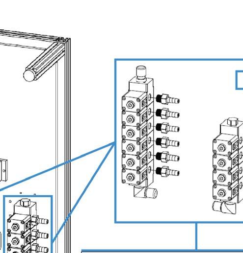
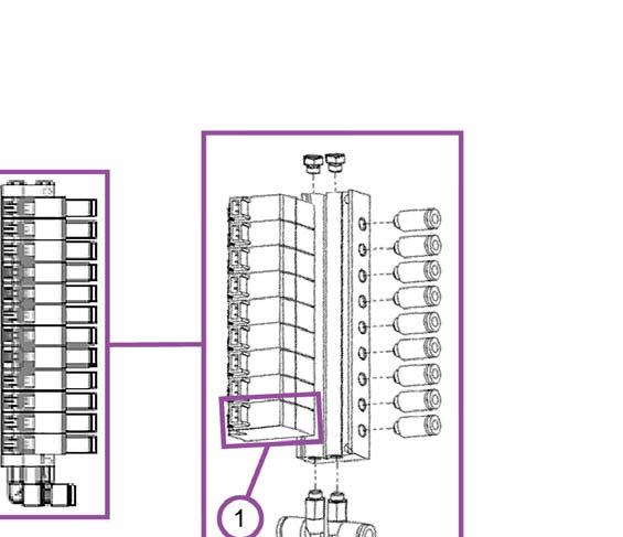
5 1. Safety Measures and Requirements Please follow these instructions carefully in order for the unit to work safely and effi ciently. Both the unit and its peripheral elements must be handled by qualifi ed technical personnel. Make sure the installation is carried out according to the current regulations of the state, county and city. Do not mount the unit on an irregular or unstable surface. This unit is designed to work in a vertical position. The unit must be installed in an area with adequate clearance, far from possible impacts, electromagnetic noise sources and pipelines of gas, steam or water. The top of the cabinet is not a shelf! Do not leave objects on the unit. Warranty is voided if the user modifi es, adds or suppresses any feature of the unit. All components involved in maintenance tasks must be the ones registered in the spare parts list supplied by the manufacturer. Otherwise the Warranty is void. The installation of the dosing system must be performed according to the instructions of this manual. Main electrical power supply must be VAC, at 60 Hz. Always use wires in good condition. The water supply to the unit must conform to the specifi cations of this manual. The high pressure air supply to the unit must conform to the specifi cations of this manual. The unit should be confi gured according to the programming manual. All chemical products must be stored in approved container, at a safe distance from the unit. The handling of chemical products requires the proper safety measures such as protective glasses, a mask and gloves. 2. General Description Pneumatic wall-mount units are designed to dose chemical products to multiple washer extractors. The maximum number of products that can be used with a single unit is 10. Regardless of the number of dosage channels the maximum number of washers the products can be distributed to by a single unit is also 10. All the components of the system are consistent with general purpose industry standards, and the materials of construction are compatible with all normal laundry products. The measurements made by the built-in fl ow meter ensure reliable, accurate and repeatable product dosage. The use of a fl ow meter also allows for additional safety measures and alarms to prevent mixing of chemicals. The pneumatic wall-mount units have four major components: 1) The collection manifold (Mounted on the main panel.) 2) The dosing channel (From the collection manifold on the main panel out to the distribution manifold.) 3) The distribution manifold, (Mounted separately.) 4) The communications boxes (To capture and transmit the signals from each washer extractor to the controller.) 1
6 When a qualifi ed signal is detected by the communication box, the unit will dose the appropriate products according to the settings of the formula and washing phase being executed. An external panel for an optional air fl ush can be used when larger doses or longer distances are required in order to deliver the chemical doses to the machines much faster and using less water. A key feature to the system is delivering up to 10 chemicals to up to 10 washers with a single, durable, pneumatic, double-diaphragm pump. Aiding in the reliability and longevity of the system is a water fl ush that cleans the entire channel after every product delivery. The collection manifold, both sides of the pump, the fl ow meter, and all the way through the distribution manifold to the washer is fl ushed with clear water, to prevent the effects of long-term chemical exposure. 3. Dimensions Pneumatic Wall-Mount Main Panel (Inches) Distribution Manifold (Inches) (6 and 8 Washer) (10 Washer) 2
7 Pneumatic Wall-Mount Main Panel (Millimeters) Distribution Manifold (Millimeters) (6 and 8 Washer) (10 Washer) 3
8 4. Pre-Installation, Installation and Mounting 4.1 Pre-Installation Survey It is highly recommended to visit the site well before installation, to familiarize yourself with the physical layout of the laundry, the machines present and their characteristics, the laundry products in use, and how any current laundry dosing system is being employed. Pay attention to the entire laundry system, its requirements and its schedules, to ensure a smooth transition to, and installation of, your Dositec laundry dosing system. Learn the operations of all the washers, as well as the products they use, and why. Determine the capacities of the machines and what is involved in programming their signals. Measure the distance between where the Dositec main panel will be installed and the location of the Distribution Manifold(s). Determine where the communication boxes will be installed for each washer, as well as the lengths of 4-conductor cable needed to daisy-chain them back to the main panel, and the lengths of 10-conductor cable from each communication box to each washer s signal terminals. Identify the voltage each washer is using for it s signals. Determine how many conductors you need for connecting the main panel and the distribution manifold(s) and the distance for that connection. Measure the lengths of chemical delivery hose that will be needed to run from the main panel to the distribution manifold(s), from the distribution manifold(s) to the washers, and back to the Calibration vase. Identify how the hoses will be routed, and what hardware will be required to accomplish that scheme. Identify where the bulk chemicals will be placed and the lengths of hose needed to connect them to the Collection Manifold of the main panel. Calculate how many hose clamps will be necessary to complete the installation. It is recommended to use the specifi c installation kit for the system being installed, which is available from Hydro Systems. If the mounting hardware is obtained from local providers, all items should be the same as the ones listed in the kit. Schedule an orderly transition from any previous dosing system in use, and investigate if any portions of that system must be removed before the installation of the Dositec system. 4.2 Main Panel Positioning In order for the Dositec laundry dosing system to operate properly it must be installed in an unobstructed location on a fl at wall. The system must also be placed at a height so that the screen is at eye level. 1-Channel Pneumatic Main Panel (in) 2-Channel Pneumatic Main Panel (in) 4 Use a drill and bit appropriate to the material the panel is being mounted on. Drill four 5/16 (8mm) diameter holes in the wall according to the measurements given. Use the four wall anchors included with the unit and insert them in the holes. Place the unit level on the wall and use the included fl at washers and screws to affi x it fi rmly. To prevent binding, put the fl at washer on the mounting bracket before inserting and tightening the screw.
9 1-Channel Pneumatic Main Panel (mm) 2-Channel Pneumatic Main Panel (mm) 4.3 Other Component Installation After mounting the main panel, locate and install the other system components: The Distribution Manifold(s) This is where the products coming from the main panel are directed to the appropriate washer. Product can only be delivered to one washer at a time, a dosage to another washer is simply postponed until the delivery channel is clear. It is common, but not necessary, to centrally locate the distribution manifold among the washers it will service. The Communication Boxes One Communication Box is required for each washer. Each box requires a 10-conductor cable to acquire the trigger signals from the signal connections of the washer. A four conductor cable is required to daisy-chain all the boxes to the PLC at the main panel. The recommended installation location is a clear place on the wall behind every washer, or on the washer itself. The Calibration Vase Since this vase is used for dosage calibration, it should be installed on the wall near the main panel. Please note the vase is connected by a hose to the distribution manifold. Make provision for draining the calibration vase and for overfl ow from the vent fi tting A Method for Routing the Delivery Hoses and Cables (Ladder Trays, PVC Pipe, Hangers and so forth) Install some method to route the hoses and cables safely and attractively out of the way of operators and machinery. Position the hoses to allow the least restrictive fl ow to the distribution manifold and washers. 4.4 Delivery Hose Connections With all the components mounted, they can be connected with the delivery hoses. A fl exible, reinforced, transparent, chemically-compatible hose of the proper inside diameter is recommended. On U.S. systems the delivery hose connections are 1/2 barb and must be secured with worm-gear hose clamps. Check the fi ttings on the washers and the chemical drum pickup systems, in case an adapter will be required. The product delivery system will require water fl ow of about 1 to 2 gallons per minute (gpm) at a dynamic (valves open) water pressure of 20 to 30 psi (1.5 to 2 bar). Do not use a water source that feeds other equipment, if during that feed the fl ow or pressure drops below these requirements. Water of a higher pressure will require a pressure regulator before the connection to the Dositec system. If necessary, install the appropriate Hydro Systems Booster Tank to supply water at the proper fl ow and pressure. Product Suction Hoses These are the hoses that connect the chemical drum pickup system to the Collection Manifold on the main panel. They allow product to be drawn into the delivery channel by the pneumatic pump during the dosage cycle. Consider how you want the chemical drums positioned to avoid having incompatible chemicals too close together, and 5
 on the right side of the collection manifold.")


10 to allow a neat routing of the hoses to the collection manifold on the main panel. Notice the water inlet is always the fi rst valve (in the direction of fl ow) on the right side of the collection manifold. Also notice how the products are connected, starting from the top down on the right side and then from the bottom up on the left side. To Distribution Manifold Overfl ow Vent From Distribution Manifold Calibration Vase Drain Input Water Source 10 Products Booster Tank Distribution Manifold Hoses The Product Delivery hose from the Main Panel runs to the Distribution Manifold. From the distribution manifold there is a hose that runs to each washer, and a hose that runs back to the Calibration Vase (which should be mounted near the main panel) The Calibration Vase solenoid should always be the rightmost and the washer solenoids should always start at the left. From the Main Panel To the Calibration Vase 6 Washer 1
11 Optional Air-Assist Flush There are generally four reasons you might consider employing the optional Air-Assist Flush Panel. 1) A long distance to some or all of the washers (over 100 feet). 2) Large dosage volumes of product to be delivered. 3) When you have short duration washer cycles. 4) Always for tunnel washers. The advantage of the air-assist fl ush is a much faster delivery than the water fl ush. The compressed air will push the product dosage to the washer very quickly and also introduce much less water into the washer than would the normal water fl ush. Delivery Hose from Main Panel Independent High Pressure Air Source To the Calibration Vase Washer High Pressure Air Connections Now it is time to connect the incoming high pressure air line to the pressure regulator on the main panel, and connect the air line from the main panel to the connection on the enclosure of the distribution manifold. The incoming high pressure air must be between 60 psi and 120 psi (4 bar to 8 bar). Set the regulator on the main panel to 0.4 MPa (4 bar / 60 psi). Both the air line coming into the main panel regulator and the air line running to the distribution manifold must be a 3/8 outside diameter plastic hose, and the fi ttings are a push-in design with no tools required. Push twice to get the hose past the sealing O-ring and the grip ring. The hose can be soft or hard plastic, but the grip ring of the push-in fi tting may not hold with harder materials. To remove a hose from these fi ttings, push the external ring toward the fi tting to release the hose so it can be pulled out. These fi ttings seal best when the hose goes straight in, not pulled at an angle. 7
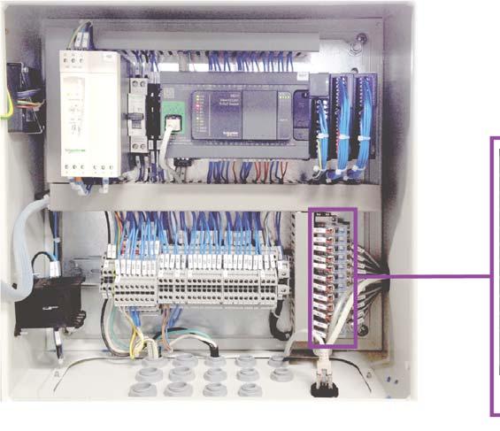
12 Set Regulator to 0.4 MPa (4 bar/60 psi) Main Panel Incoming Air Supply psi (4-8 bar) 3 x 3/8 inch O.D. (12 mm) Push-in Hose Fittings Distribution Manifold 4.6 Electrical Connections (110 VAC Main Power and Input / Output / Communications Connections) Important! Do not power up the unit until ALL input, output and communications connections are connected! Input: 110 VAC Main Power Connection The 110 Volt AC power input must be an independent 3 wire supply and a dedicated 10-amp breaker is recommended. Never use a washer as the source for the input power supply! The power cord must be plugged into a grounded three prong outlet (or equivalent) using all three wires on Bank X1 as follows: 1) Phase L connector. (Black wire in U.S.) 2) Neutral N connector. (White wire in U.S.) 3) Ground PE connector (Green wire in U.S.) 8 1) Black Wire to L 2) White Wire to N 3) Green Wire to PE Hot Black Wire to L VAC Grounded Supply Neutral White Wire to N Ground Green Wire to PE


 Product 01 connects to E04 Wire 2) Product 02 connects to E05 Wire 3) Product 03 connects to E06 Wire 4)")
13 Input: Air Pressure Sensor Connection If your system includes the optional Air Assist Flush feature, you must connect the Air Pressure Sensor to the main panel on Bank X3 at M, L1+ and E02 as shown below. Remove the jumper/bridge wire from L1+ and E02. If the Air Pressure sensor is not being connected, there must be a jumper/bridge wire from L1+ to E02 or the system will go into alarm when the air pressure test is performed. 1) Brown Wire to M 2) Yellow Wire to L1+ 3) Gray Wire to E02 Input: Drum Level Sensor Connection The Dositec Product Drum Lances have a built-in level sensor that can tell the system if the chemical drum is empty. You can have as many as ten of the level sensors connected to the main panel, on Bank X3 using E04 through E13 and L1+ for the common on ground connection. All wires are black with white numbers 1 Wire 1) Product 01 connects to E04 Wire 2) Product 02 connects to E05 Wire 3) Product 03 connects to E06 Wire 4) Product 04 connects to E07 Wire 5) Product 05 connects to E08 Wire 6) Product 06 connects to E09 Wire 7) Product 07 connects to E10 Wire 8) Product 08 connects to E11 Wire 9) Product 09 connects to E12 Wire 10) Product 10 connects to E13 Wire 11) The common ground always connects cts to L1+ 9
 the system operates normally.")


14 Input: External Emergency Stop Connection The contacts OP1 and OP2 on Bank X5 are confi gured for an External Emergency Stop function. It is a simple twowire resistance circuit, like a switch. When the circuit is closed (low resistance/continuity) the system operates normally. When the circuit is open (high resistance/no continuity) the system will perform an Emergency Stop. There is normally a jumper/bridge wire between OP1 and OP2 so the system will operate normally without an External Emergency Stop device. Remove the jumper/bridge wire when using these connections. OR Wire colors dependent on device manufacturer?? Output: External Alarm Indicator Connection The Dositec s main panel has a built-in alarm buzzer that is quite loud with a piercing sound, but it also has two contacts on Bank X5, at A13 and M, that are designed to energize an additional, external alarm indicator. The contacts are confi gured to supply 24 Volts DC, at up to 2 amps, to energize an external alarm indicator, like a strobe, buzzer or bell. OR OR 1) Green Wire to M 2) Red Wire to A13 24V DC up to 2 Amps 10


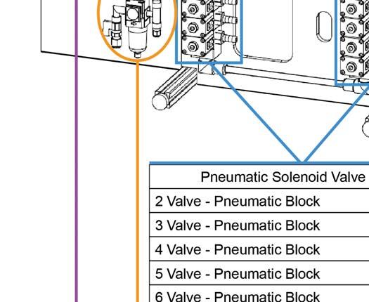
15 Output: Distribution Manifold Solenoid Connection The PLC controls the solenoids in the Distribution Manifold through connections made on Bank X6, using A20 through A29 for chemical delivery to up to 10 washers, A210 for delivery back to the Calibration Vase, and M as a common ground for all connections. (Note: The connector in the distribution manifold for the calibration vase solenoid is always marked 11, even if less than ten washers are being serviced.) All wires are black with white numbers 1 Output: Air Assist Flush Connection The optional Air Assist Flush system is controlled by the PLC using the connections on Bank X6, at A215 and M, as shown below. 1) Brown Wire to M 2) Green Wire to A215 11


16 Communication: Machine Communication Boxes The Dositec s Communication Boxes are the interface between the signals coming from the washer and the formula programming to deliver certain products at certain times. The simple On/Off signals from the washer are translated into digital packets of information and transmitted back to the Dositec PLC over a digital network. This allows a single fourwire cable to daisy-chain from one communication box to another, which greatly simplifi es installation. The connection at the main panel is on Bank X8 at L1+, M, A and B as shown below. The four conductor cable runs to the In connector of the box closest to the main panel. Any remaining boxes are connected with a cable running from the Out connector to the In connector of the next box. The boxes are identifi ed to the PLC by the DIP switch settings as shown below. If you are using the Remote Formula Selection accessory, their DIP switches must be set to match the Communication Box to which they are connected. 5. Dositec Start Up 12 When you have fi nished the physical installation of the system, you can begin the start-up procedure, detailed below: 5.1. Configuring the system settings It is necessary to defi ne all the parameters related to the unit, products, channels and washer extractors. Although you can do this at the front panel, it is easier to use the Laundrytec software to create an LM2 fi le for this installation, set all the parameters on the computer and then upload the settings to the PLC Prime the hoses that go to the washer extractors with water The hoses in the delivery channel and from the distribution manifold to the washers need to be fi lled with water. To do this, use to the calibration screen and do successive Water calibrations to each washer. Also fi ll the hose that comes back to the calibration vase by selecting it as the destination. Check for leaks before proceeding to the next step Prime the suction hoses of every product The hoses that run from product pick-up drum lances to the collection manifold on the main panel also need to be fi lled. Once again use the calibration function but this time select Product as calibration mode. You can send the fl ow to a washer or the calibration vase, releasing the button to stop the dose as soon as the product hose is fi lled to the collec-
17 tion manifold. If you are sending the fl ow to the calibration vase, open the valve at the bottom of the vase. After each calibration you will be required to run a fl ush to clean the delivery channel. If you are sending the fl ow to the calibration vase, watch out for an overfl ow when doing the fl ush. It is important to take into account the chemical incompatibilities when choosing the order of the products to prime. If the delivery channel or vase is not suffi ciently cleaned by the fl ush, do a water calibration until you are satisfi ed Calibration of Products Now that all the hoses are primed, you can do the product calibrations. Select the Product whose delivery you wish to calibrate in the calibration screen, and choose the calibration vase as the destination. Check that the valve at the bottom of the calibration vase is closed. Press and hold the calibration button while sending the dosage to the vase. Remember that the vase will begin to fi ll with water, not product, which is correct since the volume of water is the same as the volume of product being pulled from the collection manifold. Release the button to stop the dose when there is a representative sample in the vase (use the average of the maximum and minimum dose for each chemical), check the volume scale on the side of the vase and enter the actual volume pumped on the PLC touchscreen in milliliters Calibration of Water Although you could calibrate water delivery to the calibration vase, calibrating at the washer farthest from the main panel provides the worst case scenario for pumping against back pressure. Put a bucket or other container at the inlet hose for the washer, and hold the Calibration button down long enough to get a sizable volume delivered, like half a gallon (2 liters). Carefully measure the volume of water that was delivered and enter that volume in the Actual fi eld for the calibration in milliliters Check the Dosage Calibration with Manual Dose To verify the fl ow meter measurements, perform a manual dosage to the calibration vase, with the Flush option set to No, and with the valve at the bottom of the vase closed. Then confi rm the volume in the vase is the same as the manual dosage volume you entered on the PLC display. Since using the manual dose function to check the fl ow meter measurement must be done with the vase valve closed and without fl ush, you will have to open the vase valve and fl ush the delivery channel as a separate operation Adjusting Flush Time for each Washer Extractor Use the Manual Dose function (with the Flush Option set to Yes ) and send a dosage to each washer extractor. Choose a product with a noticeable color, so you can watch at the inlet of the washer extractor and see if the current fl ush volume is enough to take the full product dosage inside the washer. If the water fl ush volume needs to be adjusted, that is done on the Parameters of Washer Extractors screen Download the to the PC Once you have made the measurements, calibrations and adjustments in the previous steps, you should download the system confi guration to your computer using the Laundrytec software. Open the same LM2 fi le you used to upload to the PLC (or create a new LM2 fi le with the Laundrytec software), connect to the PLC, go to the Data Transfer section, check all the boxes that apply to your system and download from the PLC Test the System Run each washer one by one, and verify that the PLC is receiving all the washer s signals, and responding with the proper product delivery, based on the formula selected and the confi guration for each wash phase. The number of the formula and the corresponding phases must be refl ected in the View machines screen. 13

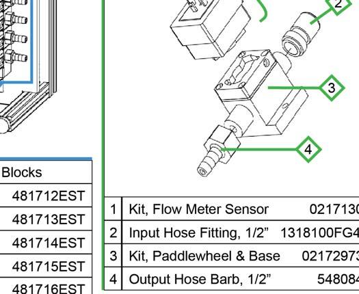
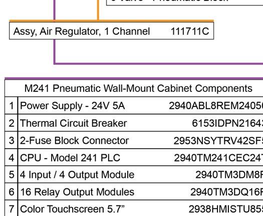
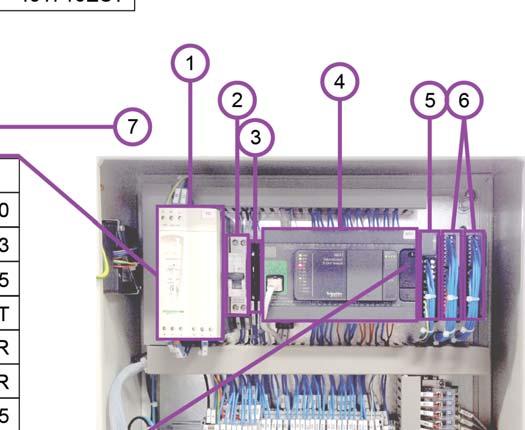
18 6. Service Parts 14


19 15
installation guide Dositec Electromagnetic Wall Mount - 1 Channel
 installation guide Dositec Electromagnetic Wall Mount - 1 Channel 2 (This page was intentionally left blank.) index 1.OO safety measures and requirements 3 2.OO general description 3 3.OO dimensions 3.01
DEMA 830 Laundry Master TM Installation Instructions
 I-656 Pg. 1 of 9 SYSTEM OVERVIEW The DEMA 830 Laundry Master is designed for long reliable use with simplicity in mind for both the installer and user. The system is based on the reliable DEMA peristaltic
DEMA 832 LAUNDRY MASTER TM INSTALLATION INSTRUCTIONS
 System Overview DEMA 832 LAUNDRY MASTER TM INSTALLATION INSTRUCTIONS The DEMA 832 Laundry Master is designed for long reliable use with simplicity in mind for both the installer and user. The system is
Advanced Laundry Chemical Dosing System for Single and Multi-Washers
 Advanced Laundry Chemical Dosing System for Single and Multi-Washers The On-Premise Elite sets the new standard for laundry chemical dosing systems by which all others will be measured! Innovative smart
American Dish Service
 American Dish Service INSTALLATION INSTRUCTIONS Model JDS12 (T) or (R) Muffler Booster (T) 12kW, 240v, 3-ph, (R) 12kW, 208v, 3-ph Manufactured by Hubbell Electric Heater Company for use on American Dish
DEMA SOLID PRODUCT LAUNDRY MASTER TM MODEL: 581L-1W and 581L-2W INSTALLATION INSTRUCTIONS
 Included Parts: A. 581.1 Solid Bowl B. 58.1LA Vacuum Breaker C. 58.6 Stainless Steel Supply Tube D. 58.29 90º Compression Fitting E. 58.24 Straight Compression Fitting F. 58.7 Vinyl Discharge Tube G. 66.123
INSTALLATION INSTRUCTIONS UNDERCOUNTER DISHWASHERS
 INSTALLATION INSTRUCTIONS UNDERCOUNTER DISHWASHERS VIKING 111 Front Street Greenwood, Mississippi 38930 USA (662) 455-1200 IMPORTANT - PLEASE READ AND FOLLOW Before beginning - please read these instructions
J-PRO V 230V Dual Voltage Hydrogen Peroxide Pump Installation & Start-Up Guide
 J-PRO-22 110V 230V Dual Voltage Hydrogen Peroxide Pump Installation & Start-Up Guide Thank you for purchasing a Clean Water System! With proper installation and a little routine maintenance, your system
PowerLogic Branch Circuit Power Meter (BCPM)
") PowerLogic Branch Circuit Power Meter (BCPM) Panel Board Monitoring System Installation Guide Branch Circuit Power Meter (BCPM) HAZARD CATEGORIES AND SPECIAL SYMBOLS Read these instructions carefully and
PowerLogic Branch Circuit Power Meter (BCPM) Panel Board Monitoring System Installation Guide Branch Circuit Power Meter (BCPM) HAZARD CATEGORIES AND SPECIAL SYMBOLS Read these instructions carefully and
SJE-Rhombus Type IFS w/c-level Sensor Installation Instructions and Operation/Troubleshooting Manual
 Installer Friendly Series SJE-Rhombus Type IFS w/c-level Sensor Installation Instructions and Operation/Troubleshooting Manual This control panel must be installed and serviced by a licensed electrician
UNIQUE USER FRIENDLY MICROMETER STYLE ADJUSTMENT
 The series hose crimper with Micrometer Style Adjustment and 80 ton cylinder has the capacity to crimp hoses up to 1-¼" 4 wire (with standard dies) and up to 1-¼" 6 wire and 2" 4 wire (with larger dies).
DEMA 813 PROBELESS DEMAMaster TM INSTALLATION INSTRUCTIONS
 DEMA 813 PROBELESS DEMAMaster TM INSTALLATION INSTRUCTIONS Models: DM-813-PLLL-1T DM-813-PDLL-1T DM-813-PLLL-2T DM-813-PDLL-2T I-729 Pg 1 of 15 System Overview The DEMA DEMAMaster probeless series is designed
P10KW / P15KW Air Dryer Installation Guide
 P10KW / P15KW Air Dryer Installation Guide This guide covers basic air dryer installation and setup only. Once installation is complete, please refer to the P10KW / P15KW User s Guide for more advanced
Removal of Non-condensable Gases and Air Is Critical In A Steam System
 Removal of Non-condensable Gases and Air Is Critical In A Steam System Air and non-condensable gases are one of the major problems in a steam system. Both can cause production problems for a steam system
UNIQUE USER FRIENDLY MICROMETER STYLE ADJUSTMENT
 The series hose crimper with Micrometer Style Adjustment and 62 tons of crimping force has the capability to crimp hoses up -¼" -2 wire, -¼" 4 wire, and " 6 wire. UNIQUE USER FRIENDLY MICROMETER STYLE
J-PRO-22 Pump Proportional Feed Chlorinator Installation & Start-Up Guide
 J-PRO-22 Pump Proportional Feed Chlorinator Installation & Start-Up Guide Thank you for purchasing a Clean Water System! Please review this start-up guide entirely before beginning to install your system
J-PRO V 230V Dual Voltage Chlorinator Installation & Start-Up Guide
 J-PRO-22 110V 230V Dual Voltage Chlorinator Installation & Start-Up Guide Thank you for purchasing a Clean Water System! With proper installation and a little routine maintenance, your system will be providing
D100S-T420 Portable Service Hose Crimpers
 The D00S-T420 Portable series hose crimper paired with either a ValPower Hand Pump, Pneumatic Pump or Multi-Electric Pump make the perfect combination for portable crimping requirements. UNIQUE USER FRIENDLY
DEMA 844 Laundry Master Laundry Chemical Dispensing
 DEMA 844 Laundry Master Laundry Chemical Dispensing Overview The DEMA Laundry Master is a digital laundry dispenser designed to dispense chemicals when signals are received from commercial laundry machines.
User s Manual. TIGER S EYE E-Series Mark V Jockey. TIGERFLOW Systems, Inc Mint Way Dallas, Texas
 User s Manual TIGER S EYE E-Series Mark V Jockey TIGERFLOW Systems, Inc. 4034 Mint Way Dallas, Texas 75237 214-337-8780 www.tigerflow.com TABLE OF CONTENTS Introduction... 4 Sequence of Operation... 5
J-PRO-22 Pump Proportional Feed Hydrogen Peroxide Installation & Start-Up Guide
 J-PRO-22 Pump Proportional Feed Hydrogen Peroxide Installation & Start-Up Guide Thank you for purchasing a Clean Water System! Please review this start-up guide entirely before beginning to install your
Laundry Dosing Systems
 revolutionary dispensing solutions Laundry Dosing Systems Advanced program Flexible and modular, the BrightLogic system is ideal for all sizes of machine from small OPL commercial washers to tunnel systems.
igate ClimaZone Zoning Panel
 igate ClimaZone Zoning Panel Installation, Configuration Manual 97B0117N03 Rev: March 3, 2016 Caution! These instructions are intended to be used by the installer or service personnel. End users are NOT
MODEL AC-SCC-5 INSTALLATION, OPERATION & MAINTENANCE MANUAL
 5CIM2-0413 W30-AC0056 MODEL AC-SCC-5 INSTALLATION, OPERATION & MAINTENANCE MANUAL Multi-zone Hydronic Chiller Interface Module SECTION 1: INTRODUCTION Unit description... 5 Location... 5 Handling... 5
WAREMAX SERIES. Dosing Systems for Commercial Dishmachines. Contents. WAREMAX Series Dishwasher systems. 4 Priming and Delime Mode.
 WAREMAX SERIES Dosing Systems for Commercial Dishmachines Contents 1 Getting started.... Page 2 2 Installation... Page 3 3 Set-Up. Page 9 4 Priming and Delime Mode. Page 11 5 Probeless Mode..... Page 12
D165-D160 SERIES HYDRAULIC HOSE CRIMPER OPERATORS MANUAL
 Page D65-D60 SERIES HYDRAULIC HOSE CRIMPER OPERATORS MANUAL SAFETY PRECAUTIONS Page MODELS COVERED This manual is applicable to different variations of the D60 Series and D65 Series Crimpers. A Standard,
INSTALLATION INSTRUCTIONS TD75. Vented tumble dryer DOMESTIC. Carefully read the instructions for use before using the dryer.
 INSTALLATION INSTRUCTIONS TD75 Vented tumble dryer DOMESTIC Carefully read the instructions for use before using the dryer. Dear Customer, Read these instructions carefully and completely before you install
Knight Trak II Instruction Manual
 Knight Trak II Instruction Manual Page 1 of 16 7$%/(2)&217(176 Drawing-System Wiring Diagram... 3 Knight Trak II System Overview... 4 Drawing-POB Wiring... 8 Drawing-LFP Wiring... 9 Drawing-Control Connections
J-PRO-24 Pump Chlorinator. Installation & Start-Up Guide
 J-PRO-24 Pump Chlorinator Installation & Start-Up Guide Thank you for purchasing a Clean Water System! With proper installation and a little routine maintenance, your system will be providing treated water
ELECTRIC COOKTOP INSTALLATION INSTRUCTIONS
 INSTALLATION AND SERVICE MUST BE PERFORMED BY A QUALIFIED INSTALLER. IMPORTANT: SAVE FOR LOCAL ELECTRICAL INSPECTOR'S USE. READ AND SAVE THESE INSTRUCTIONS FOR FUTURE REFERENCE. U.S.A. WARNING FOR YOUR
Easy Dose Chemical Injection and Dispensing System DEMA Engineering Company
 Easy Dose Chemical Injection and Dispensing System DEMA Engineering Company Overview The DEMA Easy Dose is a simple and reliable chemical delivery system. Easy Dose features an electronic control system
D3000. Installation & Setup Guide
 Page 1 of 15 17483-00 Rev B s1 April 2009 Contents Description Page Safety... 3 Installation Standards 3 Specification. 3-4 Circuit Board Connection 5 Mounting Dimensions 6 Installation Procedure 6 Mechanical
Friwa Compact. Operating instructions EN
 Operating instructions EN Version 1.1 / Edition 09/2013 Contents 1 Key background information... 3 1.1 Limitation of liability... 3 1.2 Responsibilities of the operator... 3 1.3 Documentation... 3 1.3.1
Installation instructions for vented tumble dryer DOMESTIC. Dear Customer,
 Dear Customer, Read these instructions carefully and completely before you install the machine. The installation should be carried out by a qualified person who is familiar with all local codes and ordinances
Installation. Please keep this manual for future reference.
 Installation Tecma Bathroom Anywhere Owner s and Installation Manual Please keep this manual for future reference. Read ALL these instructions before installing the Tecma Bathroom Anywhere unit. Warning
Summit E & Summit XL Dispensers for small OPL to large laundry washer extractors and tunnels
 Summit E & Summit XL Dispensers for small OPL to large laundry washer extractors and tunnels Same platform adapts to every install Summit E and XL handle up to 8 pumps E uses small and/or medium pumps,
DEMA CHEMASTER WAREWASH SYSTEM INSTALLATION AND OPERATIONS MANUAL
 DEMA CHEMASTER WAREWASH SYSTEM INSTALLATION AND OPERATIONS MANUAL DM-812-LL-2T DM-812-DL-2T I-602 Pg. 1 of 16 Rev. A-0600 Deleted: 14 CONTENTS Page Number Introduction 3 Special Features 3 System Overview
Installation instructions for condenser tumble dryer DOMESTIC. Dear Customer,
 Dear Customer, Read these instructions carefully and completely before you install the machine. The installation should be carried out by a qualified person who is familiar with all local codes and ordinances
Versatile Design Helps Solve Today s Lubrication Challenges.
 Versatile Design Helps Solve Today s Lubrication Challenges. Take a look inside we think you ll like what you see Designed from the inside-out for longer lasting performance and reliability. G3 meets changing
D A R A - 4. Data Aire Relay Auto-Changeover
 D A R A - 4 Data Aire Relay Auto-Changeover WARNING: If adding the DARA-4 panel to existing units that did not include a DARA-4 panel when originally purchased it will be necessary to add a relay or relays.
INSTALLATION INSTRUCTIONS
 INSTALLATION INSTRUCTIONS BUILT-IN BOTTOM MOUNT REFRIGERATOR/FREEZER DBRTGK72SS-GRILLE KIT (FOR designer SERIES ONLY) VIKING RANGE CORPORATION 111 Front Street Greenwood, Mississippi (MS) 38930 USA (662)
Frequently asked questions: Intelligent Transmitter Series
 Frequently asked questions: Intelligent Transmitter Series The Wilcoxon family of Intelligent Transmitters, relay alarms, and communication modules can be used to implement low-cost online vibration monitoring
PINNACLE WAREWASH CONTROL By DEMA DP-812-DL-1T DP-813-DLL-1T DP-812-LL-1T DP-813-LLL-1T Introduction
 DP-812-DL-1T DP-813-DLL-1T DP-812-LL-1T DP-813-LLL-1T Introduction The PINNACLE warewash control is a single control board design. This controls all of the system functions. The system requires a single
American Dish Service
 1 American Dish Service INSTALLATION INSTRUCTIONS Model 5-AGS or 5-AG Available in 90, 120, 150-second Time Cycles Door-type, Double-Rack, Chemical Sanitizer, Dump & Fill Dishmachine Listed by UL #E68594,
Chem-Trak Jr. Instruction Manual
 Chem-Trak Jr. Instruction Manual 0900590 Rev: B (02/10) Page 1 of 40 TABLE OF CONTENTS Specifications... 3 System Overview... 4 Operation... 5 Installation... 6 SIB and Interrupt Modules... 8 Wiring Diagram...
J-PRO-24 Soda Ash Injection Installation & Start-Up Guide
 J-PRO-24 Soda Ash Injection Installation & Start-Up Guide Thank you for purchasing a Clean Water System! With proper installation and a little routine maintenance, your system will be ph neutral water
innovation > technology > future
 Laundry systems Transaxle Technology provides added support and stability to the gear shaft. This equalizes roller pressure, extending the life of the motor gearbox and squeeze tube. innovation > technology
SPECIFICATIONS FEATURES
 FEATURES Excellent for collecting the large chips which will drop into the garbage can before reaching the impeller. The filter bag filters out the remaining sawdust down to 5 microns. With the cyclone
Energy-Free Waterers SF-2C, SF-4C, EF-2C, EF-4C
 Energy-Free Waterers SF-2C, SF-4C, EF-2C, EF-4C THANK YOU FOR PURCHASING THIS PRODUCT Behlen Country has been in the business of providing quality products for more than 80 years. Our products will provide
Air Cleaning Equipment, Inc. 303 N. Main St. Broadway, NC iers.com
 Read and Save These Instructions Horizon Galaxy - Installation and Operations Manual Air Cleaning Equipment, Inc. 303 N. Main St. Broadway, NC 27505 www.horizondehumidif iers.com 1 Safety Notes: The Horizon
COOL TOUCH ELECTRIC WATER KETTLE
 COOL TOUCH ELECTRIC WATER KETTLE MODEL:SWK-1701DB USER INSTRUCTIONS Seamless Stainless Steel Interior-Healthy Water Cool Touch Exterior-Safe To Use www.thesecura.com Welcome Congratulations on purchasing
SmartLine Pressure Transmitters Modular, Accurate and Robust for the Lowest Cost of Ownership
 Field Products SmartLine Pressure Transmitters Modular, Accurate and Robust for the Lowest Cost of Ownership Honeywell Innovation and Expertise When faced with demanding fi eld instrument application requirements,
Installation and Operation Manual. ACF-18 Automatic Chlorinating Feeder
 Installation and Operation Manual ACF-18 Automatic Chlorinating Feeder Operating Specifications Inlet Flow: 1.0-1.5 gpm Outlet Flow: = Inlet Flow Inlet Pressure: 10-45 psi Maximum Output: 26 lbs. of Available
Panel Radiators. For Buderus Panel Radiator models: Applications Manual. - Model 21 - Model 22 - Towel Warmers
 s For Buderus models: - Model 21 - Model 22 - Towel Warmers 2 08.2014 Applications manual Table of Contents 1 General Info 5 2 Safety 6 3 Product Description 7 4 Mounting Guidelines 15 5 Radiator Output
Laundry. a wide range of automatic peristaltic dosing systems. innovation > technology > future
 Laundry a wide range of automatic peristaltic dosing systems innovation > technology > future OplBasic L Dosing system with a peristaltic pump OplBasic L Dosing system with a peristaltic pump OplBasic
Installation Instructions
 Installation Instructions For Fully Integrated NoFrost Combined Refrigerator-Freezers HC 2060/2061 7082 485-00 Important PLEASE READ AND FOLLOW THESE INSTRUCTIONS These instructions contain Warning and
M770 ph Controller Owner s Manual
 M770 ph Controller Owner s Manual Table of Contents I. Introduction page 2 A. Water Chemistry page 2 B. Safety page 3 C. System Components page 4 D. Specifications page 7 E. Controller Panel Descriptions
Installation & Operating Guide
 HOT WATER DISPENSER Installation & Operating Guide Read all instructions thoroughly. Keep this guide for future reference. Proof of purchase is required for Warranty. Staple receipt or proof of purchase
D3000. Installation and Operating Manual SAFETY D3000 SPECIFICATIONS PRODUCT DESCRIPTION
 D3000 Installation and Operating Manual SAFETY Always wear the required Personal Protective Equipment (such as safety glasses, gloves, face shields, and aprons) when potentially exposed to any hazardous
Table of Contents 1. OVERVIEW SYSTEM LAYOUT SPECIFICATIONS FUNCTION... 11
 Table of Contents 1. OVERVIEW... 3 2. SYSTEM LAYOUT... 4 3. SPECIFICATIONS... 8 3.1 SYSTEM COMPONENTS...9 3.2 PLC INPUTS AND OUTPUTS...9 3.3 FUNCTION KEYS...10 3.4 DEFAULT SET POINTS AND TIMERS...10 4.
Ultrasonic Switches. Features & Benefits
 Why use an ultrasonic switch over other level technologies? Depending upon your application, there may be three or four technologies equally suited for your application; however; only one will be the best
D165 SERIES Service Hose Crimpers
 D65 SERIES Service Hose Crimpers D65 Series hose crimpers with the Micrometer Style Adjustment t and 62 tons of crimping force has the capability to crimp hoses up to " 6SP*. UNIQUE USER FRIENDLY MICROMETER
USER S MANUAL AND INSTALLATION INSTRUCTIONS IMPORTANT
 USER S MANUAL AND INSTALLATION INSTRUCTIONS P3BD Series 13 SEER Single Package Air Conditioner IMPORTANT Read this owner information to become familiar with the capabilities and use of your appliance.
Installation, Operation & Maintenance Manual. Wash System
 Installation, Operation & Maintenance Manual Wash System Kleen Flo Wash System Installation, Operation & Maintenance Manual CONTENTS Introduction and Overview... 3 Pipeline Wash System Features... 5 Wash
HDLV 55-Gallon Powder Drum Unloader
 Instruction Sheet P/N 07333 0 HDLV -Gallon Powder Drum Unloader Description See Figure. The HDLV -gallon powder drum unloader uses a Prodigy HDLV High Capacity pump to supply virgin powder to a powder
Model SU412 OPERATORS MANUAL. Manual No
 Model SU412 OPERATORS MANUAL Manual No. 513625 Rev.4 This manual provides basic information about the machine. Instructions and suggestions are given covering its operation and care. The illustrations
Installation Instructions. For the 18 Built-In Dishwasher and Front Color Panels
 Installation Instructions For the 18 Built-In Dishwasher and Front Color Panels Printed in USA 154232102 Before You Begin DO NOT INSTALL DISHWASHER UNTIL YOU HAVE READ ALL INSTRUCTIONS. FOR YOUR SAFETY,
Dishwasher installation guide
 DW80H9950US-00151A-06_EN_150216.indd 1 DW80H99* Series DW80J99* Series DW80J75* Series Dishwasher installation guide STOP These installation instructions are intended for use by qualified installers. If
INSTALLATION INSTRUCTIONS WM75. Washing machine DOMESTIC. Carefully read the instructions for use before using the washing machine.
 INSTALLATION INSTRUCTIONS WM75 Washing machine DOMESTIC Carefully read the instructions for use before using the washing machine. Dear Customer, Read these instructions carefully and completely before
INSTALLATION INSTRUCTIONS FOR 7330C740 FLUSH MOUNT CEILING ASSEMBLY
 INSTALLATION INSTRUCTIONS FOR 7330C740 FLUSH MOUNT CEILING ASSEMBLY TABLE OF CONTENTS Warnings...3 Package Contents...3 General Information...3 Supply Ducting And Registers...3 Routing 115 VAC Wiring...5
KH-80 HYDRAULIC CRIMPER OPERATORS MANUAL
 KH-80 HYDRAULIC CRIMPER OPERATORS MANUAL 1 SAFETY PRECAUTIONS READ AND IDENTIFY ALL COMPONENT PARTS BEFORE USING CRIMPER. CRIMPER CAN PRODUCE 80 TONS OF FORCE. KEEP BOTH HANDS AWAY FROM PINCH POINTS. CONSULT
American Dish Service
 1 American Dish Service INSTALLATION INSTRUCTIONS Model ASQ Glasswasher Available in 75-second cycle Undercounter, Carousel, Chemical Sanitizer, Batch-type Glasswasher Listed by UL #E68594, NSF/ANSI 3,
Single Pumps_ 2 Double Pumps _ 4. Air freshener dosing pump for air-conditioning equipments _ 7 Car Wash_ 7 Enzyme dosing pumps_ 8
 DISWASHING Single Pumps_ 2 Double Pumps _ 4 Other uses Air freshener dosing pump for air-conditioning equipments _ 7 Car Wash_ 7 Enzyme dosing pumps_ 8 LAUNDRY Dosing systems for one washer extractor_
MODEL A18 SOLVENT RECOVERY SYSTEMS (EXPLOSION PROOF UNITS)
") MODEL A18 SOLVENT RECOVERY SYSTEMS (EXPLOSION PROOF UNITS) FOR PROPER AND SAFE USE OF THIS CHEMCHAMP EQUIPMENT, PLEASE FOLLOW THIS DOCUMENT AND LOCAL AUTHORITY. KEEP THIS DOCUMENT FOR FUTURE REFERENCE.
MODEL A18 SOLVENT RECOVERY SYSTEMS (EXPLOSION PROOF UNITS) FOR PROPER AND SAFE USE OF THIS CHEMCHAMP EQUIPMENT, PLEASE FOLLOW THIS DOCUMENT AND LOCAL AUTHORITY. KEEP THIS DOCUMENT FOR FUTURE REFERENCE.
SECTION 4. Parts Management
 SECTION 4 Parts Management Honeywell s Parts Management program is a way to balance the cost of maintaining a spare parts inventory against the risk of process downtime. Honeywell works with the customer
ASSEMBLY and INSTALLATION INSTRUCTIONS. Pipe wrench Ratchet 3/8 socket 9/16 socket 11/16 socket 3/16 Allen key 3/32 Allen key 9/64 Allen key
 ASSEMBLY and INSTALLATION INSTRUCTIONS Gas Conversion Kit Tube Heaters View these instructions online at www.lbwhite.com Kit Contents: DESCRIPTION QTY. Instructions 1 Burner orifi ce 1 Manifold pipe 1
GLC/GW-100 MANUAL INSTALLATION SERVICE PARTS REV.1.01
 Owner s Manual Keep with machine for reference GLC/GW-100 MANUAL INSTALLATION SERVICE PARTS REV.1.01 CMA DISHMACHINES 12700 KNOTT STREET GARDEN GROVE, CALIFORNIA 92841 800-854- 6417 FAX 714-895- 2141 www.cmadishmachines.com
Self Cleaning decoration panel
 INSTALLATION MANUAL Decoration Provided with Filter Auto Cleaning Function Self Cleaning decoration panel Installation manual Self Cleaning decoration panel English BYCQ140CGW1 BYCQ140CGW1 Self Cleaning
NGC-UIT-ORD User interface terminal for Raychem NGC systems Installation Instructions
 NGC-UIT-ORD User interface terminal for Raychem NGC systems Installation Instructions Description The NGC-UIT-ORD is a panel mounted display used in conjunction with other approved Raychem control and
Installation Instructions
 Installation Instructions For Fully Integrated NoFrost Combined Refrigerator-Freezers HC 2062 HCB 2062 HC/HCB 20 7082 373-00 Important PLEASE READ AND FOLLOW THESE INSTRUCTIONS These instructions contain
SAVE THESE INSTRUCTIONS
 Built-In Dishwasher Dishwashers Write the model and serial numbers here: Model # Serial # You can find them on the tub wall just inside the door or. the lower part of back. Installation Instructions DDW1802W
Cascade Premier and Elite Premier Bathing Systems with Aqua-Aire Installation / Assembly Instructions
 Cascade Premier and Elite Premier Bathing Systems with Aqua-Aire Installation / Assembly Instructions Premier Elite Premier PENNER PATIENT CARE, INC Box 523 / 102 Grant St. Aurora, NE 68818 360745P Revision
TANDEM TANDEM. Premium concealed runners for wood drawers.
 TANDEM TANDEM Premium concealed runners for wood drawers www.blum.com TANDEM never fails to impress 2 For every drawer the right solution TANDEM plus BLUMOTION brings together all of the features, innovations
SCM. Micro. Streaming Current Monitor. Analyzer. Sensor/Sampler with light shield removed. The Analyzer. Instrument Overview
 Micro SCM Streaming Current Monitor A Watts Water Technologies Company Instrument Overview The instrument consists of the Analyzer and the SCM sensor. Analyzer The Analyzer The monitor has a built in graphic
Electrolux Professional Washer Extractors
 Electrolux Professional Washer Extractors Experience the world of laundry from Electrolux Follow the wave. Care and excellence Excellence is part of our philosophy: in planning, technology, design and
Owner s Manual RD432-0 Chemical Controller
 Owner s Manual RD432-0 Chemical Controller Table of Contents I. Introduction page 2 A. Water Chemistry page 2 B. Safety page 3 C. System Components page 4 D. Specifications page 7 E. Controller Panel Descriptions
Handshower, Hose & Handshower Accessories
 INSTALLATION INSTRUCTIONS P21650, P21660, P24452, P24453, P24454, P24456, P24743, P24745, P24746, P24761, P24843 1188577-2-F 2014 KALLISTA 1 of 5 THANK YOU FOR CHOOSING KALLISTA We appreciate your commitment
OPERATION & INSTALLATION MANUAL IR-30, IR-234, IR-245, IR-260, IR-288, IR-14K220, IR-18K220. Electric Tankless Hot Water Heater
 OPERATION & INSTALLATION MANUAL IR-30, IR-234, IR-245, IR-260, IR-288, IR-14K220, IR-18K220 Electric Tankless Hot Water Heater Table of Contents SAFETY INFORMATION... 1 INTRODUCTION... 2 Unit Operation...
Rules for Safe Operation
 Rules for Safe Operation Important: Do not attempt to operate the CleanStation until you have read thoroughly and understand all instructions and safety rules contained in this manual. Failure to comply
IMPORTANT WARNINGS IMPORTANT SAFETY INSTRUCTIONS
 IMPORTANT WARNINGS IMPORTANT SAFETY INSTRUCTIONS Suncourt recommends professional installation of the Airiva (or by an accomplished DIY person) Please read and save these entire instructions before starting
Installer Friendly Series In-Site. Installation Instructions and Operation/Troubleshooting Manual. Installation. Mounting the Control Panel
 Installer Friendly Series In-Site SJE-Rhombus Type IFI Installation Instructions and Operation/Troubleshooting Manual This control panel must be installed and serviced by a licensed electrician in accordance
OUTDOOR DISHWASHER INSTALLATION INSTRUCTIONS
 OUTDOOR DISHWASHER INSTALLATION INSTRUCTIONS IMPORTANT! Read all of these instructions before installing the dishwasher. AUTOMATIC HIGH LOOP The drain hose is fastened to the back of the machine at the
Installation Instructions
 Instructions for Frontload Washers Original Instructions Keep These Instructions for Future Reference. (If this machine changes ownership, this manual must accompany machine.) www.alliancelaundry.com Part
EG-400 Fire Detection Monitor
 EG-400 Fire Detection Monitor For Engine and Generator compartments Owner s manual with installation instructions Revision 2.3 (10/1/07) Our Business is Your Safety and Peace of Mind! Jim Shepherd Toll
1-866-PENNERS
 Cascade Premier and Elite Premier Bathing Systems with Aqua-Aire Installation / Assembly Instructions Premier Elite Premier PENNER PATIENT CARE, INC Box 523 / 102 Grant St. Aurora, NE 68818 360745P Revision
Viking Installation Guide
 Viking Installation Guide Viking Range Corporation 111 Front Street Greenwood, Mississippi 38930 USA (662) 455-1200 For product information, call 1-888-VIKING1 (845-4641) or visit the Viking Web site at
INSTALLATION INSTRUCTIONS
 INSTALLATION INSTRUCTIONS BUILT-IN BOTTOM MOUNT REFRIGERATOR/FREEZER BRTGK72SS-GRILLE KIT (FOR PROFESSIONAL SERIES ONLY) VIKING RANGE CORPORATION 111 Front Street Greenwood, Mississippi (MS) 38930 USA
ph Measuring System Start-up and maintenance manual e Contents
 Contents 1. Starting up 1.1 Scope of delivery: 1.2 Reconditioning 1.3 Installing the ph probe 1.4 Installing the switch cabinet 1.5 Filling the electrolyte reservoir 1.6 Installing the reference electrode
3HP MOBILE CYCLONE DUST COLLECTOR MANUAL FILTER CLEANING MANUAL
 3HP MOBILE CYCLONE DUST COLLECTOR MANUAL FILTER CLEANING MANUAL LAGUNA TOOLS 2072 Alton Parkway Irvine, California 92606 Ph: 800.234.1976 www.lagunatools.com 2018, Laguna Tools, Inc. LAGUNA and the LAGUNA
ILS Max. Installation and Operating Manual TABLE OF CONTENTS
 ILS Max Installation and Operating Manual TABLE OF CONTENTS TABLE OF CONTENTS...1 PREFACE...2 INTRODUCTION...2 System Description...2 Overview of the ILS Max...4 SPECIFICATIONS...5 FEATURES...6 SYSTEM