2
|
|
|
- Olivia Martin
- 6 years ago
- Views:
Transcription

1 Installation Operation Commissioning Maintenance N 11.47A
2 2


3 3

4 1 g c e f b j d h a i 4

5
6 4 6
7

8 9 a b 10 8
9


10 a 10


11 18 rep.2 rep.1 rep.3 rep

12 b a 12
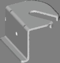
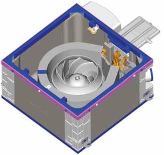
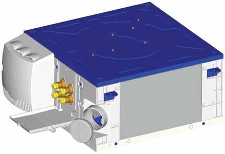
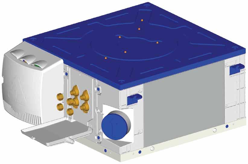
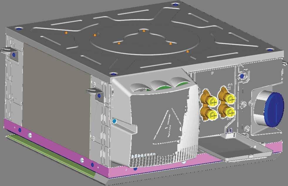
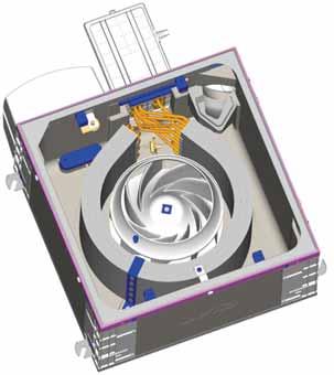
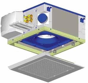
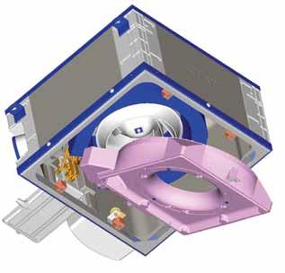
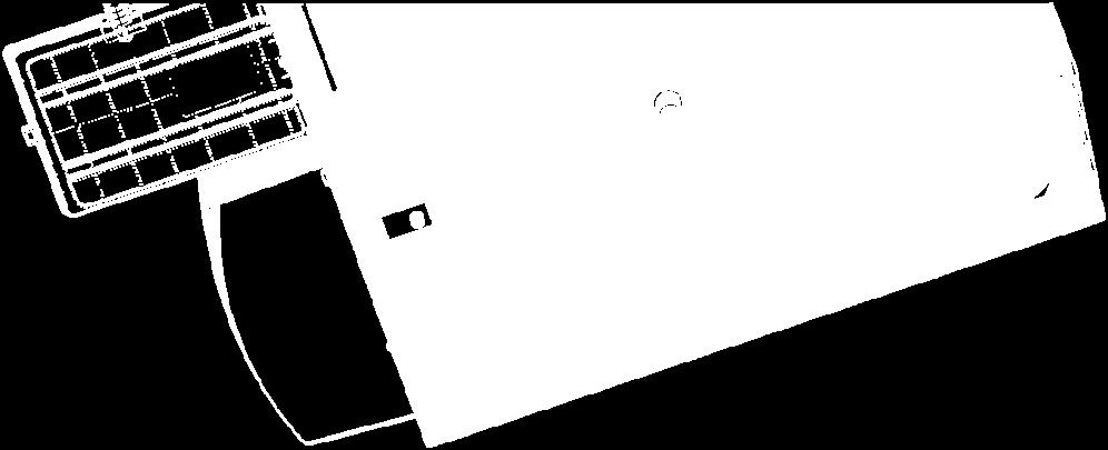
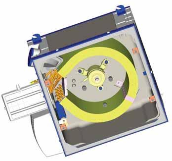
13 UNPACKING, CHECKING AND STORING THE UNIT Thank you for purchasing a CIAT unit. We trust that this CIAT unit will give you complete satisfaction. To ensure correct operation, all connections (electrical, hydraulic, etc.) must be made in accordance with industry practice and the regulations in force in the country of use. EN Your unit must be maintained as recommended in this manual. The unit is delivered in two separate packages. An air handling unit and a return/discharge panel, with a label on the packaging bearing all the details required for identification (type, model, etc.). Each unit bears a data plate. Include the reference number shown on the data plate in all correspondence. It is the recipient's duty to inspect the contents of the packages upon receipt: In the event of missing items, the customer must provide the exact number of parcels delivered. If any damage is found upon delivery, report it on the delivery receipt in the presence of the delivery driver before the delivery note is signed. IMPORTANT: In accordance with Article 133 of the French Code of Commerce, these claims must be reported to the carrier by registered letter within three business days of receipt. The terms "conditional" and "pending unwrapping" shall have no value. The client must unwrap the goods in the presence of the driver. Claims must be made at the time of delivery and be described in detail. HANDLING For your safety, wear protective gloves! Important: the unit must be handled with care and preferably laid flat. Impacts may cause damage to the frame or the body of the unit and adversely affect its main functions and its appearance. The unit should preferably be lifted using the brackets. It is possible to carry out the installation using a fork-lift truck, as long as care is taken not to damage the unit. The unit is placed inside the suspended ceiling. The unit must be fixed to the ceiling using the 4 threaded rods (not supplied) on the 4 support brackets. DESCRIPTION OF THE UNIT (fig.1) a-heat exchange coil b-fan motor assembly c-electrical box d-main condensate drain pan e-auxiliary condensate drain pan f-condensate drain g-support brackets h-air filter i-air return/discharge panel j-fresh air inlet EN -1
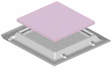
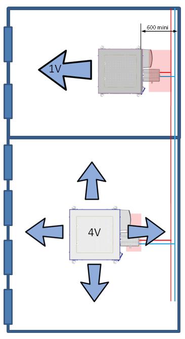
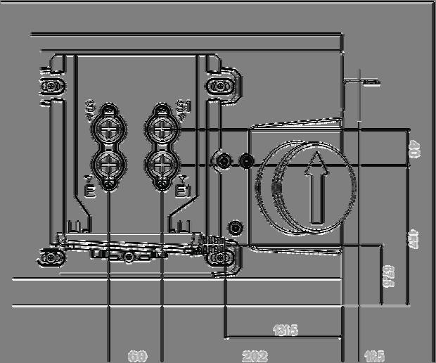
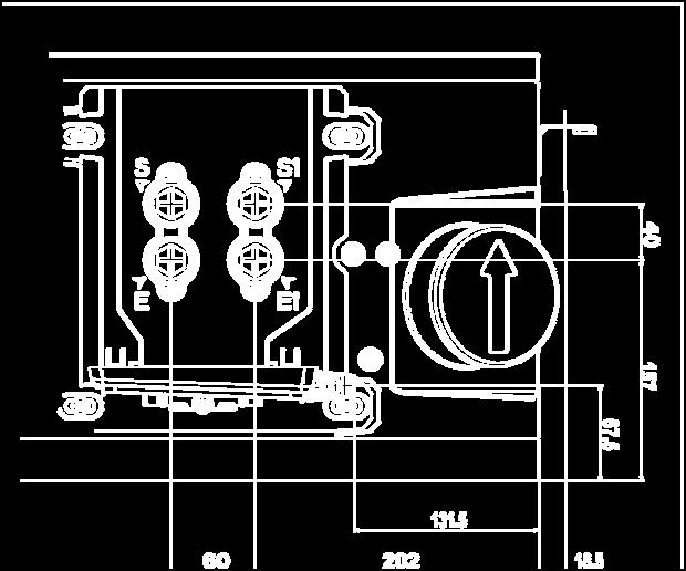
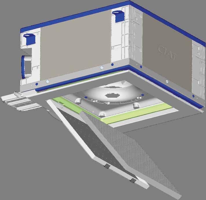
14 Data plate (fig.2) -1- Code -2- Serial number -3- Unit designation -4- Rated motor output -5- Motor rotation speed -6- Coil type -7- Wiring diagram reference -8- Motor speed wiring -9-Maximum service pressure -10- Electric heater specifications (if fitted) The data plate contains all the information required to identify the unit and its configuration. This plate is positioned on the technical face containing all the connections, above the fresh air inlet. Before contacting us, please note the serial no. and the designation. INSTALLATION & CONNECTION To prevent injury or damage to the unit or room, work must only be carried out by qualified personnel. Mechanical connections Ensure there are no obstacles in order to guarantee optimal air distribution. An electrostatic film applied to the air intake prevents dust from entering the unit during assembly and can be left in place until the diffuser is fitted in its final position. The air handling box is fitted inside the suspended ceiling at the edge of the room with the air discharge opposite windows and the electrical box facing the interior of the building for models with a 1-way return/discharge panel. For 4-way models, position the box in the centre of the room with the electrical unit facing the interior of the building. Ensure that the neighbouring suspended ceiling panels can be easily removed to allow maintenance and servicing operations to be carried out. The Coadis Line must be suspended from the ceiling using 4 threaded rods either 6 mm or 8 mm in diameter (not supplied), which are fixed to the unit's 4 support brackets using antivibration resilient mounts (optional, fig.4-a) or a nut/washer assembly positioned on either side of the mounting bracket (fig.4-b) Note: CIAT strongly recommends the use of antivibration resilient mounts when securing the unit, in order to reduce the transmission of vibrations through the building structure during operation. The fitting template (fig.3) on the air handling unit packaging allows the anchoring points for the threaded rods to be traced on the ceiling according to the selected diffusion, rep.a 1 way (1V) or rep.b 4 ways (4V). Insert the threaded rods in the notches on the support brackets. The unit must be level and resting lightly on the base of the T profiles of the suspended ceiling (fig.4-c). Important: The unit must be perfectly level in relation to the suspended ceiling to prevent condensate draining problems. For configurations with a 1-way return/discharge panel, the rear of the unit must be a sufficient distance from the wall (at least 600 mm) to allow suitable access to the hydraulic, electrical and air connections. Reminder: the air discharge is always directed towards glass partitions in order to minimise heat flow due to radiation. EN -2
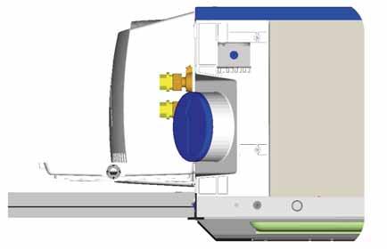
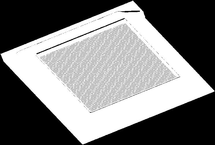
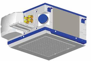
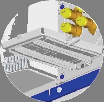
15 If a room thermostat is fitted, place it on an inside wall (not behind a door) and at a height of 1.50 m from the floor. Keep it away from sunlight and all sources of heat. Air connections EN Mounting the return/discharge panel 1-way or 4-way return/discharge panel (fig. 5): We recommend fitting this component only when the box is already installed in the suspended ceiling to prevent damage to the panel or clogging of the filter during tests when switching on for the first time. The panel is supported by a connection comprising 4 ball joints/couplers (fig.6) - Remove the electrostatic film applied to the box's air intake. - Mark the 4 positioning squares on the counter frame (fig.5). The ball joint centre to centre distances are different to prevent assembly errors. - Hold the panel with both hands at opposite corners. - Fit the panel by pressing each ball joint firmly and sharply. Attention: do not press hard on the corners of the panel as this could deform them. Check that the panel is securely affixed. The COADIS LINE has a directly integrated return/discharge interface which isolates the flow of air handled by the unit from the suspended ceiling. The use of a connecting air duct between the air return and discharge is therefore not necessary. The COADIS LINE has an inlet for clean fresh air equipped with a 100 mm diameter connection sleeve integrated in the frame, with a removable plug (fig.7). The ducts used may be coated with an anti-condensation material (fibreglass mm thick) - Remove the plug from the fresh air inlet - Position the duct on the connection sleeve - Place a retaining clamp around the duct in contact with the connection sleeve - Tighten the clamp and check the integrity of the connection If the fresh air return leads directly outside, the duct must not exceed 5 metres in length. A rain guard grille and a filter must be fitted (at installer's expense) to prevent water or other material entering from outside. If an auxiliary fan is being used (supplied by the installer), the flow of fresh air must be limited to 10% of the unit's nominal flow rate to prevent noise, coil frosting or air filter bypass problems. Hydraulic connections Water always flows into the bottom of the coil and exits at the top. The pipes are positioned in the suspended ceiling as shown in figure 8, which is also printed on the fitting template. The coils are equipped with a header coupling with flat face swivel nuts with a female thread, diameter G½ and an O-ring (supplied by CIAT) (fig.9). The header coupling is equipped with an air bleed valve (fig. 9 a) at the high point with partial draining at the low points (fig. 9 b) that can be manoeuvred using a 7 mm Allen key or a flat-blade screwdriver. EN -3
16 IMPORTANT: the coil can be partially drained, however precautions must be taken during the winter if the installation is shut down. To drain completely, air must be blown through the circuit. If the hydraulic connections are completed, it is not necessary to insulate the valves to prevent condensation (unless they are specific valves). A naturally inclined ABS auxiliary condensate drain pan is supplied with the unit. This collects condensates from the valves and coil (from the main pan) and evacuates them via gravity or using a condensate drain pump supplied as an option. Installation To avoid damaging the CIAT valves or couplings, never torque tighten to more than 3.5 dan.m. Use two wrenches, one to hold and the other to tighten to ensure a tight seal. Always fit the valve in the right direction. On the 2 CIAT couplings, the direction of flow should be A AB (A being connected to the coil and AB to the hydraulic network). The maximum allowable differential pressure for our valves (open or closed) is 100 kpa. We recommend not exceeding 60 kpa. The design of a hydraulic network is crucial to the correct operation of the system. Drain valves should therefore be placed at the appropriate points and in sufficient number. In addition, strainers should be fitted, as well as drains at circuit high points, balancing tees and shut-off valves on each coil and, if necessary, discharge valves. Filtration: An efficient filtration system (recommended efficiency of 0.5 mm) should be fitted on the water supply and return lines. Flushing: The system must be flushed completely and filled with treated water to prevent the build-up of scale or sludge in the circuit. When flushing the system, open the valve on the unit to prevent any sludge or impurities from entering the coil: Thermo valves: remove the servomotor and fit the cap, which will cause pressure to be applied to the shaft, thereby opening the passage or request that the control valve opens. 3-position modulating valves: if the power has not yet been switched on, the valve will be open by default. If the control has already been powered up, remove the servomotor to release the rod and open the passage. Filling Drain the coils during commissioning. EN -4
17 Operating limit recommendations: Cooling coil inlet minimum water temperature: 7 C Heating coil inlet maximum water temperature (2-tube application without electrical heaters): 70 C Heating coil inlet maximum water temperature (2-tube application with electrical heaters): 55 C Heating coil inlet maximum water temperature (4-tube application): 80 C Maximum operating pressure: 16 Bar Interior return air min./max. temperature: +0 C / +40 C Interior return air maximum relative humidity: 60% EN Operating recommendations: To prevent any inopportune opening of the thermo-actuators on control valves with thermal motors, the temperature of the air surrounding the thermo-actuators should not exceed 50 C. This is especially important for units installed in confined spaces (e.g. in suspended ceilings). CIAT shall not be liable for damage to valves caused by faulty design of the hydraulic supply network or incorrect commissioning. To protect against the risk of condensation when using chilled water, lagging should be placed along the entire lengths of pipes and completely sealed at its ends. When using the water coil and electric heater, we advise against using cross-linked polyethylene (PEX) pipes to supply water to the unit. This is because overheating of the electric heater could cause the water temperature to rise briefly. This could cause rapid deterioration of the PEX pipe near the unit and cause it to burst. We recommend using stainless steel braided (or equivalent) hoses for hydraulic connections. Connecting the auxiliary condensate drain pan A naturally inclined ABS auxiliary condensate drain pan with no standing water and equipped with a connecting bushing is supplied with the unit. The condensate is drained via the bushing (drain height 70 mm), which can receive tubes with an internal diameter of 15 to 20 mm. The drain hose can be separate for each unit or connected to a main drain hose sized to allow the condensates from all the units to flow through at the same time. Use a clear flexible and/or rigid drain pipe for a minimum slope of 1 cm/m, with a constant gradient along its whole length and no low points. Install a siphon measuring at least 5 cm to prevent unpleasant gases or odours exiting the hose. Electrical connections Disconnect the electrical supply to the unit before carrying out any work. Only personnel qualified to perform electrical work may make electrical connections. Before connecting the unit to the network, ensure that the voltage matches that indicated on the motor's data plate (230/1/50-60Hz). EN -5
18 Coadis Line Input power (W) Input current (A) Motor code AC Asynchronous Motor HEE Brushless Motor V V V V V V V V V V An earth connection is compulsory. CIAT shall not be liable for incidents resulting from faulty or non-existent earthing. Always follow the circuit diagram delivered with unit. Circuit diagrams for customer applications should be based on the diagrams supplied: Unit wiring for 2-pipe systems (fig.10). Unit wiring for 4-pipe systems (fig.11). Unit wiring for 2-pipe systems with an electric heater using 2 heating elements (P=900 or 1200W Max) (fig.12). Note: if necessary, the output of the 300W electric heater can be reduced by removing the shunt positioned between terminals 8 and 9. CIAT recommends using a system that controls the unit in relation to the temperature of the water (to actuate the valve(s)) and the use of an electric heater. All the electrical connections are routed into the electrical box indicated by. The electrical box is equipped with a cable grommet to allow the cables to be routed up to the terminal block. To access the electrical terminal block: Disconnect the unit from the electrical power supply. Use a screwdriver to undo, but not remove, the lateral retaining screw on the electrical box casing (fig.13). Modifying the motor speeds: a screwdriver must be used to install the wiring. The COADIS LINE offers a choice between two types of motor technology: asynchronous and brushless (low consumption). Asynchronous motor: to optimise the unit's performance and depending on the type of control used. The unit has five speeds numbered V1 to V5 connected to the terminal block in the electrics box (V1= low speed and V5= high speed). The customer must cable the speeds for the thermostat at the top of the terminal block between V1 and V5. EN -6
19 To open a connection point and change the cabling (fig.14): - Place the end of a flat-blade screwdriver in the hole located just below the cable to be removed. - Release the cable and move it to the marker for the desired speed. - Place the screwdriver again in the hole just below the desired speed, insert the cable and remove the screwdriver; this ensures a secure contact. EN Repeat the procedure for the remaining customer speeds. Important: the wires coming from the motor and connected to terminals V1 to V5 must never be interconnected. IMPORTANT: it is essential to refit the electrical box casing once all the cabling and adjustment operations are complete. Brushless motor: this has a motor speed electronic control unit which uses a 0-10V control signal or 3- speed on/off control (to be selected by the customer depending on the controller or thermostat used with the unit). - Controller or thermostat for 3-speed on/off control: - Switch on the unit and select the ventilation speed to be modified using the thermostat. - Use the "CIAT speed control unit" accessory supplied as an option to adjust each speed (rpm) in accordance with the N08-43 instructions included with the speed control unit. - Controller managing a 0-10V control signal: - The 0-10V setpoint voltage information is issued by the controller itself. Refer to the operating and configuration instructions supplied by the manufacturer. N.B.: If electric heaters are used, the lowest speed setting should never be below 400 rpm. To prevent any risk of damage, never connect several asynchronous or brushless fan coil unit motors in parallel for the same thermostat. IMPORTANT NOTE: Brushless motor The electrical connection for CIAT Comfort Units must be made in compliance with international standard IEC (Electrical Installations for Buildings). The leakage current on all our comfort units conforms to the requirements of IEC (Safety of household and similar electrical appliances): - Complete comfort unit (with electric elements) equipped with a multi-speed motor: maximum leakage current = 2mA - Complete comfort unit (with electric elements) equipped with an HEE motor (brushless technology): maximum leakage current = 4.5mA. Electromagnetic compatibility in accordance with Emission standard (EN , Tool class) and Immunity (Residential, commercial and light industry class). Important: The unit's compliance with the above standards does not guarantee the compliance of the installation as a whole (several other factors not relating to the unit may be involved). As a result, the installer must observe the applicable recommendations in order to guarantee compliance. General safety instructions for units with electric elements: The rotation speed of the HEE motor must never be below 400 rpm. Fan control: the electric heater must be controlled by the fan. Power to the electric elements should be cut whenever the fan motor assembly is stopped intentionally or unintentionally. Ensure that the type of control chosen when the system is completely shut down allows post ventilation of the comfort unit (we recommend a post ventilation period of 2 minutes). Units equipped with heating elements are protected against accidental overheating by 2 temperature limiting thermostats (fig.15), 1 with manual reset (1) and 1 with automatic reset (2). EN -7
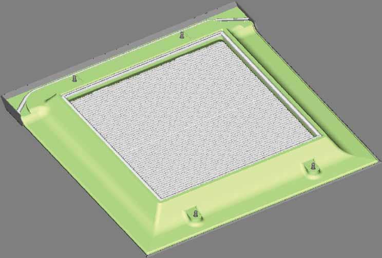
20 Do not reset these thermostats until the potential causes of the overheating have been checked: Powering up without the fan. Filter partially clogged Coil and fan stopped simultaneously by control. SERVICING AND MAINTENANCE The unit must be serviced periodically between the heating and cooling seasons. In particular, components prone to clogging (filter, condensate drain pan, coil, etc.) must be checked. work. Disconnect the electrical and hydraulic supplies to the unit before carrying out any AIR FILTER The filter is crucial to the correct operation of the unit. Without it the heat exchange coil would become clogged, the performance drop and the unit's sound level rise. The COADIS LINE is equipped as standard with an EPURE high-efficiency pleated filter. We recommend replacing the filter every two years. If maintenance is carried out more frequently, the filter can be cleaned by running a vacuum attachment in the opposite direction to the flow of air. The above recommendations are for information only. CIAT recommends regular inspections of the filter's appearance in order to define the frequency with which it should be replaced, which varies depending on the premises and the operating conditions. To guarantee optimal thermal, acoustic and air purification efficiency throughout the unit's life, CIAT recommends the use of an EPURE filter. Using a different type of filtration system could compromise the performance of the unit and be detrimental to users. Accessing the filter (fig.16): - Mark the two retaining lugs (a) positioned on the micro perforated return air grille - Push the two lugs to release the return air grille. - Lower the hinge-mounted return air grille until it is at right angles to the diffuser. - Release the filter from its housing. - After fitting a new filter, refit the return air grille. Lock it near to the panel by simultaneously pushing the two lugs sharply upwards. - Check that the grille is securely affixed. Note: The micro perforated return air grille must never be pushed in beyond the discharge panel EN -8
21 CONDENSATE DRAIN PANS The main and auxiliary condensate drain pans must be kept clean. The pans and drainage fittings may be completely cleaned using non-abrasive, water-based detergents. Also check periodically that the drain pipe is not blocked. Removing the pans: EN - To remove the auxiliary pan (fig.17), undo the screw located under the pan and release it from its position. - To remove the main pan (fig.18): Hold the panel with both hands at opposite corners. Pull the return/discharge panel towards you to release the ball joints from their housings (1) Next, undo the retaining screw using a screwdriver to separate the pan from the frame (2). Tilt the pan (approx. 30 ) downwards (3) and release it from its retaining lugs (4). To refit, perform the operation in reverse order. FAN MOTOR ASSEMBLY Periodically check the cleanliness of the impeller and the motor. If necessary, clean them using a vacuum cleaner. Handle the vacuum attachment carefully to avoid damaging them. The electric motor's bearings are lubricated for life and do not require specific maintenance. Removing the fan motor assembly: - Open the electrical unit - Disconnect the wires which form the fan motor assembly bundle. - Hold the panel with both hands at opposite corners. - Pull the return/discharge panel towards you to release the ball joints from their housings - Undo the retaining screw on the main condensate drain pan using a screwdriver (fig.18). - Remove the pan by tilting it (approx. 30 ) downwards and release it from its retaining lugs (fig.18). - Undo the retaining screw for the impeller and its foolproofing device (fig.19) using a screwdriver and remove the impeller - Remove the grommet cap (fig. 20, no. 1) - Pull the fan motor assembly bundle towards the interior of the box - Undo the 3 motor retaining screws and remove the motor (fig.20). To refit, perform the operation in reverse order. HEAT EXCHANGE COIL A clean coil is crucial to the efficiency of the unit. If necessary, clean the coil with a vacuum cleaner. If the coil must be disassembled on account of a leak: Disconnect the electrical supply to the unit before carrying out any work. Removing the coil - Insulate the unit hydraulically from the network and drain the coil. - Disconnect the coil inlets and outlets - Hold the panel with both hands at opposite corners. - Pull the return/discharge panel towards you to release the ball joints from their housings - Undo the retaining screw on the main condensate drain pan using a screwdriver (fig.18). EN -9
 - Undo the 2 screws on the coil retaining clamp (fig.")
22 - Remove the pan by tilting it (approx. 30 ) downwards and release it from its retaining lugs (fig.18). - Undo the retaining screw for the impeller and its foolproofing device using a screwdriver and remove the impeller (fig.19) - Undo the 2 screws on the coil retaining clamp (fig. 21-a) and the coil connecting plate screw (fig. 21-b). - Remove the coil To refit, perform the operation in reverse order, remembering to bleed the coil before refilling with water. RETURN/DISCHARGE PANEL Wipe the walls with a damp, slightly soapy sponge and buff them using a soft, dry cloth. Never use abrasive products. CE CERTIFICATE OF CONFORMITY CIAT's products carry the CE mark, demonstrating that they may be sold throughout the European Union. This mark is your assurance that CIAT's products are safe to use. TESTING & WARRANTY All our units are tested and proven before leaving the factory. They are guaranteed against all manufacturing defects. CIAT shall not be held liable for any type of corrosion. CIAT's warranty does not cover damage resulting from incorrect electrical wiring, inadequate electrical or thermal protection or failure to use a filter. CIAT's warranty on motors is limited to the terms of warranty extended by its supplier. Work performed on the motor by the installer will invalidate the corresponding warranty EN -10
Installation Operation Maintenance. Ductable water unit FWD FWD-SVX01D-E4
 Installation Operation Maintenance Ductable water unit FWD 08-12 - 20-30 - 45 General Information Foreword These installation, operation and maintenance instructions are given as a guide to good practice
Installation Operation Maintenance
 Installation Operation Maintenance DUCTABLE WATER UNIT FWD 08-12 - 20-30 - 45 General Information Foreword These installation, operation and maintenance instructions are given as a guide to good practice
Empty unit Cover Water Total weight 15 kg 8 kg 10 kg 33 kg
 DE LUXE Substation Introduction The HERZ DE LUXE Substation is a firmly mounted unit for providing hot water. In contrast to a hot water boiler which heats and then stores the water before it is being
Lo-Carbon T-series Window & Roof Models
 Lo-Carbon T-series Window & Roof Models Installation & User Instructions WIRED 456165A (9 WW) 456168A (9 RF) 456173A (12 WW) 456176A (12 RF) WIRELESS 456169A (9 WW) 456172A (9 RF) 456177A (12 WW) 456180A
40LM Hz INSTALLATION, START-UP AND SERVICE INSTRUCTIONS CHILLED WATER FAN COIL UNIT
 Carrier International Sdn. Bhd. Malaysia INSTALLATION, START-UP AND SERVICE INSTRUCTIONS CHILLED WATER FAN COIL UNIT 40LM 120-200 50Hz CONTENTS: Physical Data & Dimension 1-3 Safety Considerations 4 Rigging
WAILEA OWNER S MANUAL
 WAILEA OWNER S MANUAL The blades in each pack are matched for equal weight to assure smooth fan operation. If more than one fan is being installed, be careful not to mix blades from different cartons.
For Models FF2310APS, FF2310APW, FF2310APB 55cm FREESTANDING FRIDGE FREEZER. Instruction Manual
 For Models FF2310APS, FF2310APW, FF2310APB 55cm FREESTANDING FRIDGE FREEZER Instruction Manual Please read these instructions carefully before use and retain for future reference. Before switching on your
the new generation of cassette comfort units Innovative casing (Flexiway concept) integrates perfectly into suspended ceilings Air purification system
 integrates perfectly into suspended ceilings Air purification system") the new generation of cassette comfort units Innovative casing (Flexiway concept) integrates perfectly into suspended ceilings Air purification system VISUAL 360 VISUAL 180 Cooling capacity: 1 kw to 6
the new generation of cassette comfort units Innovative casing (Flexiway concept) integrates perfectly into suspended ceilings Air purification system VISUAL 360 VISUAL 180 Cooling capacity: 1 kw to 6
FUN I / FUN U FUN I MCP / FUN U MCP FUN V / FUN V MCP
 OPERATION INSTRUCTIONS MANUAL DUCTED FAN COILS UNIT FUN I / FUN U FUN I MCP / FUN U MCP FUN V / FUN V MCP 1 CONTENTS 1. GENERAL... 3 2. INSTALLATION... 4 3. AIR CONNECTIONS... 5 4. WATER CONNECTIONS...
Installation and Operating Instructions
 Installation and Operating Instructions Models: Verso 4G Hob As part of Parmco Appliances commitment to improving and updating product ranges, we reserve the right to alter, change and update technical
NA B AIR COMPACT. Instruction manual
 NA 08.41 B 09-2015 AIR COMPACT Instruction manual EN CONTENTS PAGE 1 - RECEIPT OF THE UNIT 2 1.1 Delivery/Reservations 2 1.2 Storage precautions 2 1.3 Packaging 2 1.4 Handling 2 2 - SAFETY INSTRUCTIONS
INSTALLATION, USE AND MAINTENANCE MANUAL HIGH PRESSURE FAN COIL FOR PROFESSIONAL APPLICATIONS, BUILT-IN VERSION
 INSTALLATION, USE AND MAINTENANCE MANUAL HIGH PRESSURE FAN COIL FOR PROFESSIONAL APPLICATIONS, BUILT-IN VERSION a-life2 HP 302 1202 a-life2 HP 304 1204 EN OBSERVATIONS In order to use the unit correctly
T-SERIES. Window & Roof Models. Installation, Set-up and Operating Instructions. 230V/1/50Hz
 T-SERIES Window & Roof Models Installation, Set-up and Operating Instructions Stock Ref. Nos. WIRED 456165A (9" WW) 456168A (9" RF) 456173A (12" WW) 456176A (12" RF) WIRELESS 456169A (9" WW) 456172A (9"
HEAT RECOVERY AIR HANDLING UNIT
 HEAT RECOVERY AIR HANDLING UNIT OPERATION MANUAL KOMFORT_L v2(2)_en.indd 1 07.08.2015 15:0:44 CONTENTS Introduction General Safety regulations Transportation and storage regulations Manufacturer's warranty
Panel Fan Series Operators Manual (Galvanized and Polymer)
") Panel Fan Series Operators Manual (Galvanized and Polymer) Galvanized Panel Fan with Three Wing Blade IMPORTANT: READ AND SAVE THESE INSTRUCTIONS Read all instructions carefully before attempting to assemble,
Panel Fan Series Operators Manual (Galvanized and Polymer) Galvanized Panel Fan with Three Wing Blade IMPORTANT: READ AND SAVE THESE INSTRUCTIONS Read all instructions carefully before attempting to assemble,
G-7s. Instruction Manual. G-Series Cooler COUNTERTOP COOLER. Part No.11IPA
 G-Series Cooler COUNTERTOP COOLER Part No.11IPA-061000 Instruction Manual FOR YOUR FUTURE REFERENCE This easy-to-use manual will guide you in getting the best use of your cooler. Remember to record the
G-10s. Instruction Manual. G-Series Cooler UPRIGHT COOLER. Part No.11IPA
 G-Series Cooler UPRIGHT COOLER Part No.11IPA-062800 Instruction Manual FOR YOUR FUTURE REFERENCE Thank you for using our product. This manual will guide you in getting the best use of your cooler. Remember
Centrif Duo & Centrif Duo Plus
 Centrif Duo & Centrif Duo Plus Installation and Wiring Instructions Stock Ref. N Centrif Duo P 25 61 20D Centrif Duo T 25 62 20D Centrif Duo DP 25 63 20D Centrif Duo HTP 25 64 20D Centrif Duo Centrif Duo
AUTOMATIC GRANULAR ICE FLAKER
 AUTOMATIC GRANULAR ICE FLAKER INSTRUCTIONS AND WARNINGS 24480 rev. 01 It is strictly forbidden to reproduce this instruction manual or any part thereof. Dear Customer, Congratulations on choosing a
Lo-Carbon Quadra Centrifugal Fan
 Lo-Carbon Quadra Centrifugal Fan Installation and Wiring Instructions Stock Ref. N Quadra TP Quadra TM Quadra HTP 439251A 439253A 439181A 220-240V~50Hz IPX4 PLEASE READ INSTRUCTIONS IN CONJUNCTION WITH
HORIZONTAL MULTISTAGE CENTRIFUGAL PUMP
 HORIZONTAL MULTISTAGE CENTRIFUGAL PUMP WWPPCHLFT260 Instructions WWPPCHLFT260_Horizontal Multistage Centrifugal Pump_IB.indd 1 READ THIS MANUAL CAREFULL BEFORE INSTALL, START THE PUMP 1. Suction 2. Plug
Rif Cod i220-0
 15 52 50 6 13 53 51 2 9 8 3 20 19 18 5 1 7 14 10 4 17 Rif Cod 1 0010060 2 0060287 3 0060310 4 0080003 5 0080004 6 0080051 7 0080053 8 0080410 9 0080413 10 0080430 11 0080432 12 0080434 13 0080435 14 0080436
Instructions for installation and use English. More documents on: H B /09
 TM Instructions for installation and use English EN More documents on: www.zodiac-poolcare.com H0538700.B - 2015/09 Read this manual carefully before installing, maintaining or repairing this appliance!
Panel Fan Series Operators Manual (Galvanized and Polymer)
") Panel Fan Series Operators Manual (Galvanized and Polymer) 52" Belt Drive, Galvanized Panel Fan with Three Wing Blade IMPORTANT: READ AND SAVE THESE INSTRUCTIONS Read all instructions carefully before
Panel Fan Series Operators Manual (Galvanized and Polymer) 52" Belt Drive, Galvanized Panel Fan with Three Wing Blade IMPORTANT: READ AND SAVE THESE INSTRUCTIONS Read all instructions carefully before
USER S MANUAL BUCKET FAN SERIES BUCKET FAN WHISPER SERIES
 USER S MANUAL BUCKET FAN SERIES BUCKET FAN WHISPER SERIES Bucket Fan 420 Bucket Fan 1055 Bucket Fan 1460 420 1055 1460 2 Bucket Fan CONTENT INTRODUCTION 3 USE 3 WHAT S INCLUDED IN THE BOX 3 DESIGNATION
1. Description INSTRUCTION FOR AIR BLAST COOLER TYPE COOL 450
 1. Description General The cooler is used for cooling of water, oil or other liquid by use of air. The liquid is passing in the tubes where it transfere the energy to the air via the fins on the outside
AGEO CALEO. Water-to-water high temperature heat pumps USE RANGE DESCRIPTION. Designed to replace a conventional boiler and produce domestic hot water
 Designed to replace a conventional boiler and produce domestic hot water Heating capacity : 16 to 25 Heating Hydraulic module ENVIRONMENTALLY HFC R4A PROTECTION DE FRIENDLY L'ENVIRONNEMENT USE CIAT is
Installation and maintenance instructions for cabin units type vertical IDAC (V50)
") GB Installation and maintenance instructions for cabin units type vertical IDAC (V50). Application. Bundled parts. Handling. Marking. Weight. Transport. Storage 5. Installation 5. Mounting 5. Water trap
GB Installation and maintenance instructions for cabin units type vertical IDAC (V50). Application. Bundled parts. Handling. Marking. Weight. Transport. Storage 5. Installation 5. Mounting 5. Water trap
Suits all KPF849 models
 Kambrook - Australia Ground Floor, Suite 2, 170-180 Bourke Rd Alexandria NSW 2015, Australia Locked Bag 2000 Botany NSW 1455 Customer Service Line 1300 139 798 Customer Service Fax 1800 621 337 www.kambrook.com.au
INSTALLATION OF DURAVENT POLYPRO SINGLE WALL POLYPROPYLENE VENTING SYSTEMS
 SUPPLEMENT VENTING INSTRUCTIONS FOR INSTALLATION AND OPERATION INSTRUCTION MANUALS FOR THE FOLLOWING PRODUCT TYPES: HIGH EFFICIENCY CONDENSING COMMERCIAL, COMMERCIAL POWER DIRECT VENT, LIGHT DUTY COMMERCIAL
Hardwired Electric Garage Heater
 Hardwired Electric Garage Heater G73 OWNERS MANUAL Read and save these instructions. 2 Trust has to be earned, and we will earn yours. Customer happiness is the focus of our business. From the factory
Electric Garage Heater
 Electric Garage Heater G73 OWNERS MANUAL Read and save these instructions. A Name You Can Trust Trust has to be earned and we will earn yours. Customer happiness is the focus of our business. 2 From the
1. Description INSTRUCTION FOR BLAST COOLER TYPE COOL 250. Material
 1. Description General The cooler is used for cooling of water, oil or other liquid by use of air. The liquid is passing in the tubes where it transfere the energy to the air via the fins on the outside
INVERTER SPLIT - TYPE
 INVERTER SPLIT - TYPE ISSUE No 2 DATE 04/09/08 P/No 2020323A2868 CONTENTS SAFETY PRECAUTIONS Warning 2 Operating temperature 2 BEFORE INSTALLATION Tools needed for installation 3 Items required for installing
S Y D. HWP 35, 47, 58 (c/w EC Motor & UC7 Controller) Ducted Water Cooled R410A Packaged Air Conditioner. Installation & Maintenance
 Ducted Water Cooled R410A Packaged Air Conditioner. Installation & Maintenance") HWP 35, 47, 58 (c/w EC Motor & UC7 Controller) Ducted Water Cooled R410A Packaged Air Conditioner Installation & Maintenance Fig. 1 Nomenclature Nomenclature e.g. H W P 3 5 C K Series Size Type S Y D GENERAL
HWP 35, 47, 58 (c/w EC Motor & UC7 Controller) Ducted Water Cooled R410A Packaged Air Conditioner Installation & Maintenance Fig. 1 Nomenclature Nomenclature e.g. H W P 3 5 C K Series Size Type S Y D GENERAL
QUICK CONNECT INSTALLATION MANUAL DUCTLESS MINI-SPLIT SYSTEM FOR MODELS: 2PAMSHQC12 2PAMSHQC18 2PAMSHQC24 2PAMSHQC36
 QUICK CONNECT DUCTLESS MINI-SPLIT SYSTEM INSTALLATION MANUAL FOR MODELS: 2PAMSHQC12 2PAMSHQC18 2PAMSHQC24 2PAMSHQC36 Before using your air conditioner, please read this manual carefully and keep it for
INSTALLATION MANUAL. Split-type Air Conditioner (Cooling and Heating) Outdoor Unit UQB09JJWC UQB12JJWC. Indoor Unit AQB09JJWC AQB12JJWC
 Outdoor Unit UQB09JJWC UQB12JJWC. Indoor Unit AQB09JJWC AQB12JJWC") AQB09JJ6WC_IM_E_2585 2006.4.17 4:26 PM Page 17 INSTALLATION MANUAL Indoor Unit AQB09JJWC AQB12JJWC Outdoor Unit UQB09JJWC UQB12JJWC ENGLISH FRANÇAIS ESPAÑOL Split-type Air Conditioner (Cooling and Heating)
AQB09JJ6WC_IM_E_2585 2006.4.17 4:26 PM Page 17 INSTALLATION MANUAL Indoor Unit AQB09JJWC AQB12JJWC Outdoor Unit UQB09JJWC UQB12JJWC ENGLISH FRANÇAIS ESPAÑOL Split-type Air Conditioner (Cooling and Heating)
S D HWP 77, 96. Ducted Water Cooled R410A Packaged Air Conditioner. Installation & Maintenance. Fig. 1 Nomenclature. Fig.
 HWP 77, 96 Ducted Water Cooled R410A Packaged Air Conditioner Installation & Maintenance Fig. 1 Nomenclature Nomenclature e.g. H W P 7 7 C K Series Size Type S D GENERAL HWP - A general designation which
Contents. 1. Instructions for safety and use 20
 Contents 1. Instructions for safety and use 20 2. Positioning in the counter top 21 2.1 Fixing to the supporting structure 21 2.2 Positioning the adhesive sponge 22 2.3 Positioning the fastening clips
OPTIONAL SPRING MTG HANGING CENTRES WATER CONN'S: TWO BSP MALE. 19 mm (3/4") ELECTRICAL CONDUIT HOLES ACCESS PANEL OUT (WATER) IN 485 MOUNTING
 ELECTRICAL CONDUIT HOLES ACCESS PANEL OUT (WATER) IN 485 MOUNTING") HWP 117 225 Ducted Water Cooled R410A Packaged Air Conditioner Dimensions (mm) Fig. 1 HWP 117 60 1210 SPRING MOUNTING CENTRES 690 (HEIGHT = 370) FILTER BOX PROJECTION Net Weight 105 kg Installation & Maintenance
HWP 117 225 Ducted Water Cooled R410A Packaged Air Conditioner Dimensions (mm) Fig. 1 HWP 117 60 1210 SPRING MOUNTING CENTRES 690 (HEIGHT = 370) FILTER BOX PROJECTION Net Weight 105 kg Installation & Maintenance
QZHW Fan Coil Unit. Key features. Specifications
 Key features High wall installation Cooling ( pipes) Low noise level Electrical heating coil ECM version for low energy consumption QZHW is a high wall fan coil unit available in sizes and many different
Lo-Carbon Quadra SELV
 Lo-Carbon Quadra SELV Installation and Wiring Instructions Stock Ref. N Quadra SVTP 442865 Quadra SVHTP 442866 Quadra SVTM 442867 Safety Extra Low Voltage IPX7 PLEASE READ INSTRUCTIONS IN CONJUNCTION WITH
MODULAR AUTOMATIC GRANULAR ICE FLAKER
 MODULAR AUTOMATIC GRANULAR ICE FLAKER INSTRUCTIONS AND WARNINGS 24479 rev. 03 It is strictly forbidden to reproduce this instruction manual or any part thereof. Dear Customer, Congratulations on having
Instruction Manual - Anti-Siphon Ejector Chlorine & Sulfur Dioxide 500 PPD (10 kg/h) Maximum Capacity
 Maximum Capacity") - Anti-Siphon Ejector Chlorine & Sulfur Dioxide 500 PPD (10 kg/h) Maximum Capacity 100 PPD (2 kg/h) Chlorine or Sulfur Dioxide 250 & 500 PPD (5 & 10 kg/h) Chlorine or Sulfur Dioxide Anti-Siphon Ejector
- Anti-Siphon Ejector Chlorine & Sulfur Dioxide 500 PPD (10 kg/h) Maximum Capacity 100 PPD (2 kg/h) Chlorine or Sulfur Dioxide 250 & 500 PPD (5 & 10 kg/h) Chlorine or Sulfur Dioxide Anti-Siphon Ejector
PANEL FAN SERIES OPERATORS MANUAL (Galvanized and Polymer)
") PANEL FAN SERIES OPERATORS MANUAL (Galvanized and Polymer) Galvanized Panel Fan IMPORTANT: READ AND SAVE THESE INSTRUCTIONS Read all instructions carefully before attempting to assemble, install, operate
PANEL FAN SERIES OPERATORS MANUAL (Galvanized and Polymer) Galvanized Panel Fan IMPORTANT: READ AND SAVE THESE INSTRUCTIONS Read all instructions carefully before attempting to assemble, install, operate
Installation manual. Tumble dryers T4130. Compass Control
 Installation manual Tumble dryers T4130 Type N1130 Compass Control Installation manual in original language 487 05 41 61/EN 2011.09.16 Contents 3 Contents Safety precautions... 5 Technical data... 7 Setup...
GCG-9. Instruction Manual. G-Series Cooler. Manual is for the following models: GCG-9-N13EB G-9-N13EB GCG-9-B13EB UPRIGHT COOLER
 G-Series Cooler UPRIGHT COOLER Manual is for the following models: -N13EB G-9-N13EB -B13EB Instruction Manual FOR YOUR FUTURE REFERENCE This easy-to-use manual will guide you in getting the best use of
Indholdsfortegnelse. Danvent Air Handling Units SERVICE MANUAL
 Indholdsfortegnelse Danvent Air Handling Units SERVICE MANUAL Service Servicing of the Air Handling Unit Your ventilation system is equipped with a Danvent Air Handling Unit (AHU) which will contribute
GCG-10. Instruction Manual. G-Series Cooler. Manual is for the following models: GCG-10-N33EB G-10-N33EB UPRIGHT COOLER
 G-Series Cooler GCG-10 UPRIGHT COOLER Manual is for the following models: GCG-10-N33EB G-10-N33EB Instruction Manual Manual is for the following models: GCG-10-N33EB G-10-N33EB Instruction Manual GCG-10
40cm Pedestal Fan with Remote Control
 Instruction Manual 40cm Pedestal Fan with Remote Control Model: HF40BRG READ AND SAVE THESE INSTRUCTIONS Please read and follow the instructions in this user manual even if you feel you are familiar with
Aquaciat Free cooling
 Aquaciat Free cooling NA 08.144 A 01-2009 Installation Operation Commissioning Maintenance CONTENTS PAGE Receiving the unit 2 Unloading 2 Think safety 2 Warranty 2 Storage 2 Installation 2 Hydraulic diagram
FloPro e3 H C /01. Instructions for installation and use - English. More documents on:
 FloPro e3 Instructions for installation and use - English Filtration pump Translation of the original instructions in french EN More documents on: www.zodiac-poolcare.com H0538700.C - 2017/01 WARNINGS
TEMSPEC INC. VERTICAL FAN COIL UNIT MODELS TVA, TVE, TVS
 6720 Columbus Road Mississauga, Ontario Canada, L5T 2G1 Tel: (905) 670 3595 Fax: (905) 670 3592 Web: www.temspec.com TEMSPEC INC. VERTICAL FAN COIL UNIT MODELS TVA, TVE, TVS INSTALLATION AND MAINTENANCE
VERTICAL COOKING PRECISIO/PRECIJET COMBI OVEN PRECISIO/ PRECIJET OVENS S.A.V. MAINTENANCE AND REPAIR
 VERTICAL COOKING S.A.V. PRECISIO/ PRECIJET OVENS MAINTENANCE AND REPAIR 27/03/2012 PPS-3BEFM10PC GENERAL Tools Every time this symbol appears, it is imperative to have the appropriate tool in order to
installation and operation manual for Hunter Ceiling Fans
 For Your Records and Warranty Assistance Model Name: Catalog/Model No.: Serial No.: Date Purchased: Where Purchased: For reference also attach your receipt or a copy of your receipt to the manual. installation
Vertical Stack Fan Coil Units Models: TVA, TVE, TVS
 6720 Columbus Road Mississauga, Ontario Canada, L5T 2G1 Tel: (905) 670 3595 Fax: (905) 670 3592 www.temspec.com Vertical Stack Fan Coil Units Models: TVA, TVE, TVS INSTALLATION, OPERATION AND MAINTENANCE
Installation, Operation and Maintenance Instructions Document Ref:
 Panther Fan Coil Units Installation, Operation and Maintenance Instructions Document Ref: Dunham-Bush Ltd, Downley Road, Havant, Hants PO9 2JD 023 9247 7700 info@dunham-bush.co.uk 126-000-001-C UK:www.dunham-bush.co.uk
USER S MANUAL. Heat (Energy) Recovery Ventilator. Vents Frigate HRV 120 S Vents Frigate ERV 120 S
 Recovery Ventilator. Vents Frigate HRV 120 S Vents Frigate ERV 120 S") USER S MANUAL Heat (Energy) Recovery Ventilator Vents Frigate HRV 120 S Vents Frigate ERV 120 S 2 Frigate HRV(ERV) 120 S CONTENT Introduction... 3 Application... 3 Delivery set... 3 Unit designation key...
USER S MANUAL Heat (Energy) Recovery Ventilator Vents Frigate HRV 120 S Vents Frigate ERV 120 S 2 Frigate HRV(ERV) 120 S CONTENT Introduction... 3 Application... 3 Delivery set... 3 Unit designation key...
INSTRUCTION MANUAL MODEL: 690E
 1 INSTRUCTION MANUAL ALEKO Drywall Sander MODEL: 690E READ THROUGH CAREFULLY AND UNDERSTAND THESE INSTRUCTIONS BEFORE USE Visit our web site for more great products, parts and accessories: 2 3 4 5 6 Caution!
G-10f/GCG-10f UPRIGHT COOLER
 G-Series Cooler G-10f/GCG-10f UPRIGHT COOLER Manual is for the following models: G-10F, G-10-F33EB GCG-10F, GCG-10-F33EB GCG-10F2, GCG-10-F233EB G-10-F33EB-HC, GCG-10-F33EB-HC GCG-10-F233EB-HC Instruction
FWC153, FWC304, FWC604 & FWC624
 FWC153, FWC304, FWC604 & FWC624 Wine Coolers Installation, use and maintenance www.cda.eu Important The CDA Group Ltd cannot be held responsible for injuries or losses caused by incorrect use or installation
THERMOSTATIC EXPANSION VALVES AND THERMOSTAT CONTROL DEVICES
 FUNCTION Thermostatic expansion valves are used to regulate and cut-off the flow of the heat transfer fluid that circulates inside airconditioning system terminals (radiators, fan coils, etc.). Thermostat
HOT WASHER MODEL NO: KING150
 WARNING: Do not use the hot washer without reading this manual HOT WASHER MODEL NO: KING150 PART NO: 7320175 OPERATION & MAINTENANCE INSTRUCTIONS LS1215 INTRODUCTION Thank you for purchasing this CLARKE
CTE9. Extractor. Installation, use and maintenance.
 CTE9 Extractor Installation, use and maintenance www.cda.eu Contents: 3 Important 5 Important information 6 Using your extractor 7 Care and maintenance 9 Troubleshooting 10-13 Installation 10 Installation
OPERATING INSTRUCTIONS
 EN TABLE AND STAND FAN OPERATING INSTRUCTIONS Read the instructions carefully before operating the appliance or carrying out maintenance operations. Observe all the safety instructions; failure to observe
HE120, HE160 Humidifier Installation Kit
 HE120, HE160 Humidifier Installation Kit INSTALLATION INSTRUCTIONS WELCOME To the comfortable world of humidified air. When you use your Honeywell humidifier, you notice that your skin is not as dry, and
Panther Fan Coil Units
 Panther Fan Coil Units Installation, Operation and Maintenance Instructions. Dunham-Bush Ltd, Downley Road, Havant, Hants PO9 2JD Tel. 023 9247 7700 Fax. 023 9245 3601 PDS-1200 1200-F-02 0226-04 (Global)
High temperature air-to-water heat pumps
 Designed to replace conventional boilers and produce domestic hot water 4 High temperature hot water (+65 C) 4 Winter operation (-20 C) 4 High energy efficiency (CP) 4 Compact and quiet 4 Scroll compressors
CENTRAL AIR CONDITIONER SPLIT SYSTEM
 CENTRAL AIR CONDITIONER SPLIT SYSTEM WITH ELECTRONIC CONTROL SERIES: DS INSTALLATION INSTRUCTIONS INDEX GENERAL... 2 UNIT LOCATION CRITERIA... 2 DIMENSIONAL DRAWINGS... 3 INDOOR UNIT INSTALLATION... 5
INSTALLATION AND MAINTENANCE MANUAL MINI AIR HANDLING UNIT «MISTRAL»
 INSTALLATION AND MAINTENANCE MANUAL MINI AIR HANDLING UNIT «MISTRAL» 1 1. Presentation 3 2. Generalities 3 2.1. Warnings Generalities 4 2.3. Safety instructions 4 3. Reception - Storage Installation 4
Ceiling Sweep Fan Assembly Instructions
 Ceiling Sweep Fan Assembly Instructions CSF Series Installation Note: This fan must be installed by a licenced electrical contractor Improperly installed ceiling sweep fans can be dangerous and expensive
READ AND SAVE THESE INSTRUCTIONS
 Instruction Manual 30cm Metal Desk Fan Model: MDF30 READ AND SAVE THESE INSTRUCTIONS Please read and follow the instructions in this user manual even if you feel you are familiar with the product, and
SH3020 USER INSTRUCTIONS
 DEHUMIDIFIER SH3020 USER INSTRUCTIONS GUARANTEE This product is guaranteed for 2 years from the date of original purchase. If any defect arises due to faulty materials or workmanship, the unit will, either
HEATING AND VENTILATION
 SECTION 14-102.04 14-102.04/ 1 2007OC19 DESCRIPTION The heating, ventilation and air conditioning (HVAC) system is designed to optimize passenger comfort. The system regulates interior vehicle atmosphere,
TABLE OF CONTENTS. NOTE: Read the entire instruction manual before starting the installation. TROUBLESHOOTING... 13
 R 410A Duct Free Split System Air Conditioner and Heat Pump Product Family: DFS4(A/H) System, DFC4(A/H)3 Outdoor, DFF4(A/H)H Indoor NOTE: Read the entire instruction manual before starting the installation.
Operating instructions
 ebm-papst Mulfingen GmbH & Co. KG Bachmühle D-74673 Mulfingen Phone +49 (0) 793-0 Fax +49 (0) 793-0 info@de.ebmpapst.com www.ebmpapst.com CONTENTS. SAFETY REGULATIONS AND NOTES. Levels of hazard warnings.
SAFETY OPERATION & MAINTENANCE MANUAL X-405 CARPET EXTRACTOR This unit is intended for commercial use.
 SAFETY OPERATION & MAINTENANCE MANUAL X-405 CARPET EXTRACTOR This unit is intended for commercial use. READ AND FOLLOW ALL INSTRUCTIONS, WARNINGS AND CAUTIONS BEFORE USING THIS EXTRACTOR Address: 777 South
OWNER S GUIDE SEQUENTIAL THERMOSTATIC SHOWER VALVE. 150mm Inlet Pipe Centres. Shower Control. Handles and. may differ depending.
 SEQUENTIAL THERMOSTATIC SHOWER VALVE 150mm Inlet Pipe Centres Shower Control Handles and Concealing Plate may differ depending on Model OWNER S GUIDE ISSUE 02 These instructions cover all exposed or concealed
MW402 Integrated Dishwasher
 MW402 Integrated Dishwasher Manual for Installation, Use and Maintenance 1 Customer Care Department The Group Ltd. Harby Road Langar Nottinghamshire NG13 9HY T : 01949 862 012 F : 01949 862 003 E : customer.care@cda.eu
MALIBU STAR OWNER S MANUAL
 MALIBU STAR OWNER S MANUAL CONTENTS INTRODUCTION...................................................................... 1 MOUNTING RECOMMENDATIONS..........................................................
INSTALLATION MANUAL COMFORT...BUILT TO LAST. 9,000, 12,000 and 18,000 BTU SINGLE-ZONE DUCTLESS MINI-SPLIT SYSTEM Heat Pump
 COMFORT...BUILT TO LAST 9,000, 12,000 and 18,000 BTU SINGLE-ZONE DUCTLESS MINI-SPLIT SYSTEM Heat Pump INSTALLATION MANUAL INDOOR UNIT: 1PAMSH09-SZW-14.5 1PAMSH09-SZW-15 1PAMSH12-SZW-15 1PAMSH18-SZW-15
UL U TR LTRASONIC S ONIC SCALE ALER PIEZO MINI
 ULTRASONIC SCALER PIEZO MINI CONTENTS XI - SYMBOLS 1. INTRODUCTION 1 Alternating current Type BF device 2. WARNINGS 1 3. PRESENTATION 1 3.1 Presentation 1 3.2 Technical description 2! Warning, please refer
READ AND SAVE THESE INSTRUCTIONS
 Instruction Manual 45cm Pedestal Fan Model: PED45CG READ AND SAVE THESE INSTRUCTIONS Please read and follow the instructions in this user manual even if you feel you are familiar with the product, and
INSTALLATION INSTRUCTIONS WARRANTY
 QT FLOW CENTER INSTALLATION INSTRUCTIONS Fig. 1. Low Head Pump Center Flow Chart Fig. 2. High Head Pump Center Flow Chart NOTE: Read the entire instruction manual before starting the installation. WARRANTY
Owner s Manual STOVES. MODELS 620 Kitchenaire. 621 Kitchenaire 711S
 Owner s Manual STOVES MODELS 620 Kitchenaire 621 Kitchenaire 711S CONTENTS 2 Introduction 2 Unpacking 2 Installation 2 Electrical Installation 3 Safety Advice 3 Control Panels 4 The Oven 5 Solid Plates
Porter & Charles OPERATION MANUAL. Gas Cooktop CG60S, CG76S, CG90S, CG60W, CG90W
 Porter & Charles OPERATION MANUAL Gas Cooktop CG60S, CG76S, CG90S, CG60W, CG90W Congratulations on the purchase of your Porter & Charles appliance. We are sure it will provide many years of great cooking
HOT AIR GENERATOR WITH GAS BURNER NA11.45 A GGS. Installation Operation Commissioning Maintenance
 Installation Operation Commissioning Maintenance HOT AIR GENERATOR WITH GAS BURNER GGS NA11.45 A 06-2011 04-2011 CONTENTS 1. DESCRIPTION OF THE UNIT 2. INSTALLATION & CONNECTION 3. COMMISSIONING 4. CARE
fwc152 / fwc303 / fwc603 / fwc623 Wine Coolers Manual for Installation, Use and Maintenance
 fwc152 / fwc303 / fwc603 / fwc623 Wine Coolers Manual for Installation, Use and Maintenance Customer Care Department The Group Ltd. Harby Road Langar Nottinghamshire NG13 9HY T : 01949 862 012 F : 01949
ACN SMOKE INSTALLATION AND MAINTENANCE
 NovAx ACN SMOKE INSTALLATION AND MAINTENANCE 918149-0 English 918149-0 GB Installation and maintenance NovAx smoke exhaust fan type ACN smoke 1. Application 2. Handling 2.1 Marking 2.2 Weight 2.3 Transport
Installation, Operation, and Maintenance Information
 Installation, Operation, and Maintenance Information Air Cooled Condensers 8-2016 Rev 0 Table of Contents General Safety Information 2 Inspection 2 Installation 2 6 Rigging and Assembly 2 Unit Location
Hardwired Electric Garage Heater
 Hardwired Electric Garage Heater G73 OWNERS MANUAL v1.0 Read and save these instructions. Manual v1.1 2 A Name You Can Trust Trust should be earned and we will earn yours. Customer happiness is the focus
52 CEILING FAN READ AND SAVE THESE INSTRUCTIONS FAN RATING AC 120V.
 Irene 52 CEILING FAN READ AND SAVE THESE INSTRUCTIONS FAN RATING AC 120V. 60Hz TABLE OF CONTENTS Tools and Materials Required... 1 Package Contents... 1 Safety Rules... 2 Mounting Options... 3 Hanging
Chiltrix 5.1 Thin DC - Inverter Water Fan Coil Unit Floor, Wall or Ceiling Universal Mount Manual
 Chiltrix 5.1 Thin DC - Inverter Water Fan Coil Unit Floor, Wall or Ceiling Universal Mount Manual Version 1.5 1 CONTENTS CHAPTER 1 GENERAL INTRODUCTION...3 1. Preface... 3 2. Product Introduction... 3
GB User and maintenance manual
 GB User and maintenance manual IMPORTANT SAFETY INSTRUCTIONS These instructions shall also be available on website: docs.whirlpool.eu. YOUR SAFETY AND THAT OF OTHERS IS VERY IMPORTANT This manual and
FWC152, FWC303, FWC603 & FWC623 Wine Coolers Installation, Use and Maintenance
 FWC152, FWC303, FWC603 & FWC623 Wine Coolers Installation, Use and Maintenance Customer Care Department The Group Ltd. Harby Road Langar Nottinghamshire NG13 9HY T : 01949 862 012 F : 01949 862 003 E :
THERMOSTATIC EXPANSION VALVES AND THERMOSTAT CONTROL DEVICES
 FUNCTION Thermostatic expansion valves are used to regulate and cut-off the flow of the heat transfer fluid that circulates inside airconditioning system terminals (radiators, fan coils, etc.). Thermostat
ROTA-SPRAY PROCESSOR MODEL 1210 (ROTARY-JET) INSTRUCTIONS MEGA PART NO: &
 INSTRUCTIONS MEGA PART NO: &") ROTA-SPRAY PROCESSOR MODEL 1210 (ROTARY-JET) INSTRUCTIONS MEGA PART NO: 500-702 & 500-713 PLEASE READ IMPORTANT UNPACKING INSTRUCTIONS 1. Carefully consider where the unit will be located. It should be
ROTA-SPRAY PROCESSOR MODEL 1210 (ROTARY-JET) INSTRUCTIONS MEGA PART NO: 500-702 & 500-713 PLEASE READ IMPORTANT UNPACKING INSTRUCTIONS 1. Carefully consider where the unit will be located. It should be
USER S MANUAL. Heat Recovery Ventilator. Vents Brig HRV 200 Vents Brig HRV 300
 USER S MANUAL Heat Recovery Ventilator Vents Brig HRV 200 Vents Brig HRV 300 2 Brig HRV 200 (300) CONTENT Introduction... 3 Application... 3 Delivery set... 3 Unit designation key... 4 Basic unit dimensions...
EVAPORATIVE COOLER PUMPS
 EVAPORATIVE COOLER PUMPS ebmpapst Evaporative Cooler Pump EBMALPHA $144.65 @ 1. metre Head @ 2. metre Head Power Supply 32 litres/min 25 litres/min 24V/1/5Hz Nominal Watts 5 watts Outlet Connection 2mm
OIL COOLER INSTRUCTION HANDBOOK
 OIL COOLER INSTRUCTION HANDBOOK INDEX 1. GENERALITY 2 1.1 OPERATING RANGE 1.2 IMPORTANT 2. INSTALLATION 3 2.1 TRANSPORTATION 2.2 INSTALLATION LOCATION 2.3 PIPING 2.4 WIRING (see the electrical diagram