Connect the power supply and equipment to supply to the controller is displayed for the
|
|
|
- Osborne Thomas
- 6 years ago
- Views:
Transcription
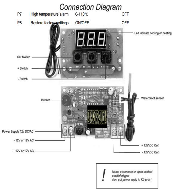
1 User Manual XH-W1301 Connect the power supply and equipment to supply to the controller is displayed for the measurement of temperature. Time you press the SET button, the display temperature flashing, Press + - to set the desired temperature (hold down the + - quickly lift) press SET to confirm the setting is complete return the controller to set the auto-relay-off! The thermostat output 10A relay, meet a variety of high-power load connected to the control circuit, power supply to the thermostat, the display shows the ambient temperature, Lights, digital control and buzzer status LED: flashes to indicate cooling or heating start-up delay, Always the relay is closed Digital tube: LL sensor open circuit, please follow the instructions to connect the sensor; HH Forces beyond the measurement range thermostat off the relay; --- high temperature alarm Buzzer: LL, HH --- digital display, the buzzer beep - beep - beep - beep sound Parameter Function Description Long press SET 5 seconds to enter the main menu settings return + - switch P0... P8 long press the SET or 10 seconds of no key activity controller automatically recognized P0 refrigeration, heating mode Long press SET 5 seconds to display a P0, press SET operating mode, heating mode + - Switch [H] [C cooling mode] and press the SET returns, long press SET or 10 seconds of no key activity controller automatically recognized complete Cooling mode: When the temperature measurements temperature set point, cooling relay pull the chiller start; when the temperature measurement value temperature set point - hysteresis, refrigeration relay is switched off, cooling off Heating mode: When the temperature measurement value temperature set point, the heating relay pull the heater starts; when the temperature measurements temperature set point + hysteresis heating relay is switched off, the heater is turned off
2 P1 hysteresis setting Long press SET 5 seconds, P0, + - Switch to P1, press SET to set back to the difference, Press + - to set the hysteresis finished, press SET to return, long press SET or 10 seconds no key the action controller automatically confirm completion Cooling mode: When the measured temperature set value, the relay, cooling starts; when the temperature measurement value settings - back to the difference, the relay is switched off, the cooling is turned off. Such as the environment is 30 setting is 25 C, hysteresis is set to 2 C, after power relay is closed refrigeration to start the relay off when cooling to 23 C cooler Close, this time due to the cooler has been disconnected the temperature began to rise, when the pick-up to the set value 25 C, the relay is closed refrigeration start again, and so forth loop to control the temperature not higher than 25 C Heating mode: When the temperature measurement value settings, relay, heater start; when the temperature measurement value set value + hysteresis value, the relay is switched off, the heater is turned off. Such as the environment of 10 C set value of 25 C, hysteresis is set to 2 C, after power relay is closed heater starts, when heated to 27 C, the relay is switched off the heater off, this time due to heater has been disconnected temperature began to drop, the moment down to the set value of 25 C relay closes when the heater is started again, and so forth loop control temperature not lower than 25 C P2 highest temperature setting limit: To avoid the misuse of others led to the set temperature is too high risk, maximum cap on the thermostat, limit the maximum temperature set point temperature control setting range SET 5 seconds to display P0 + - switch to P2, SET the maximum + - Set the maximum set temperature and the maximum is 110 finished, press SET to return, long press SET or
3 10seconds keystrokes controller automatically confirm completion For example: setting can only be set up to 60 C To temperature set point higher temperatures expand the scope of, you need to adjust the limit values for the 60 temperature set point. P3 is the lowest temperature setting limit: To avoid others to misuse the temperature is too low occurrence of ice block, the thermostat lowest setting upper and lower limits, defining the minimum temperature set point temperature control setting range SET 5 seconds to display P0 + - Switch to P3, press SET to set the minimum lower limit, Press + - to set the minimum set temperature, the minimum value of -50 finished, press SET to return, long press SET or 10 seconds of no key activity controller automatically confirm completion For example: 2 temperature set point minimum can only be set to 2 C if you want the temperature set point lower temperature range to expand, you need to adjust the settings of the lower limit. P4 temperature correction When measuring temperature and standard temperature deviation with special needs or because the user hardware, you can use this feature correction, the corrected temperature = temperature before correction + correction value of the effective range of -7.0 to 7.0 Long press SET 5 seconds to display P0 + - Switch to P4, correction time the SET, positive + - Set the school, finished, press SET to return to long press the SET or 10 seconds of no key activity controller automatically confirm completion For example, the normal display is 25 degrees; temperature correction display is 0 to 25 degrees; temperature is corrected to 1.5 to 26.5 degrees; temperature correction ; P5 delayed start time: minutes
4 Refrigeration or heater delay of need, on delay functions to protect the life of the equipment Long press SET 5 seconds, P0 + - switch to P5 time the SET set delay start time in minutes, press the SET + - Set a scale of 0-10, finished, press SET to return long or 10 seconds the keystrokes controller automatically confirm the completion of The first power cooling mode: If the current temperature settings, the cooler will not start immediately after refrigeration, you need to run the set delay time startxh-w1301 MANUAL UK 3 Heating mode: power is first applied, if this temperature set value, the heater does not immediately start the heating, the need to run the set delay time after start Refrigeration or heater adjacent two starts downtime between more than delay the start time settings, refrigeration immediately start; Shut down for the first time between the start of the refrigeration or heater adjacent two less than the delay start time, the need to run to completion set refrigeration equipment to start the delayed start time setting and start again. The delay time from shutdown instantly. Such as refrigeration state set a delay of 5 minutes, start-up delay after boot refrigeration, refrigeration When you reach the desired temperature refrigeration stop, then start the timer after 5 minutes, open the next time the cooler completion of the start timing immediately unfinished timing to wait for the end of the timing to work, delay LED blinks Delay start is set to 0 is equal to the turn off delay function The P6 key tone switch Long press SET 5 seconds, P0 + - switch to P6 time the SET is turned on key sound, press the + - Set the on / off, finished, press SET to return, long press SET or 10 seconds of no key activity control automatically confirm completion Buzzer switch points on / off is set to on key action with the key issue drops sound set to off to turn off the buzzer, no voice P7 high temperature alarm
5 SET 5 seconds to display P0 + - switch to P7, press SET to display the on / off (set to off to turn off the sub-function) is set to on, press SET to set the temperature of the high temperature alarm point, press the + - setting 0 ~ 110, after the completion of time the SET returns, long press SET or 10 seconds of no key activity controller automatically confirm the completion of the High temperature alarm setting range is or closed off times to reach rapid buzzer beeps high temperature alarm, and forced off the relay For example, we want to give a liquid or space heating to 40 degrees, set 80 degrees as dangerous temperature in the course of their work force majeure due to external causes the temperature is above 80 degrees the temperature danger, the start temperature alarm relays to disconnect the buzzer shortness alarm, a timely reminder of the staff to take appropriate measures to recoup their losses! Alarm temperature can be set according to actual needs, if you do not want the temperature is set to off, note that when returns to normal temperature automatic discharge temperature alarm thermostat work properly P8 restore the factory settings Some man-made causes lead to confusion in the internal settings of the thermostat, to set one by one is very time-consuming, can use this function to restore the factory settings, the specific method SET 5 seconds to display P0 + - switch to P8, SET is set to on or off and on to restore the factory settings, off no action finished, press SET to return, long press SET or 10 seconds the bell no key controller automatically restore the factory settings parameters in the table below
6
7
SA-3841 User Manuel. 1U 4 Fans Unit with Thermostat Sensor. Version 1.1 Copyright All Rights Reserved
 SA-3841 User Manuel 1U 4 Fans Unit with Thermostat Sensor Version 1.1 Copyright 2015 www.norcotek.com, All Rights Reserved Contents 1. Introduction 1. Overview 2. Specification 3. What's In The Box 2.
Toll Free: Tel: Fax:
 Toll Free: 1-888-865-6888 Tel: 510-226-8368 Fax: 510-226-8968 Email: sales@rackmountmart.com Copyright 2015 Synergy Global Technology Inc. All rights reserved. RA4007 User Manuel 1U 4 Fans Unit with Thermostat
WH7016E Thermostat Product Manual
 WH7016E Thermostat Product Manual Shenzhen Willhi Electronics Co., Ltd. Tel :0755-29539385 Fax :86-0755 -2953 9395 Technical support: Engineer Tian 1 Installation opening size: 2 Wiring diagram: 1 2 3L
Parts introduction FRONT BACK
 Lando Industrial Water Chillers installation instructions Thank you for using the machine from Shenzhen Lando Technology Industrial Co.,Ltd.. Please read the installation instructions carefully before
H&T Household Thermostat Design Introduction
 H&T Household Thermostat Design Introduction Year 2011 Content 1 2 3 4 5 The working principle and characteristics of thermostat H&T thermostat design features H&T thermostat design advantage H&T thermostat
User manual CLIMATIC 200/400 - Controller. Providing indoor climate comfort
 User manual CLIMATIC 2/4 - Controller Providing indoor climate comfort MUL35E-56 9-26 INDEX CONTENTS PAGE INDEX 1 GENERAL DESCRIPTION 2 THE KEYPAD, Climatic 2 3 THE KEYPAD, Climatic 4 4 THE KEYPAD REMOTE
DOLKPS1KB Programming & Installation Manual
 VANDAL RESISTANT BACK-LIT WEATHERPROOF ACCESS CONTROL KEYPAD WITH WIEGAND OUTPUT & DATA I/O DOLKPS1KB Programming & Installation Manual FOR ELECTRIC LOCK, INTER-LOCK AND SECURITY SYSTEM INSTALLATIONS DOLKPS1KB
Operation 8085C ENGLISH. Customer Support: or Visit our webiste Printed in China
 Operation 8085C MENU PROGRAM RESET ENGLISH MENU PROGRAM RESET Customer Support: 888-515-2585 or Visit our webiste www.ritetemp-thermostats.com Printed in China 1-402-006 Operation 8085C PG 1 Day Indoor
Mobile Type Air Conditioner
 Mobile Type Air Conditioner 1. Features 2. Specification 3. Wiring diagram 4. Trouble shooting 5. Electronic function 36 1. Features 1.1The currently manufactured mobile air conditioners include the following
Carbon Monoxide Transmitter
 Introduction The CO Transmitter uses an electrochemical sensor to monitor the carbon monoxide level and outputs a field-selectable 4-20 ma or voltage signal. The voltage signal may also be set to 0-5 or
LCF Touch Modbus Datasheet Application Security Advice Caution
 LCF Touch Modbus Electronic Fan Coil Thermostat with Touch Display (Flush mounting) Datasheet Subject to technical alteration Issue date: 3.11.214 Application Modern design flush mounting fan coil room
DOLKPL1KB DOLKPS1KB DOLKSF1KB
 DOLKPL1KB DOLKPS1KB DOLKSF1KB USER MANUAL INSTRUCTIONAL VIDEO 1] Connection Terminals 2] Basic Wiring Example 3] Quick Start Guide 4] Programming Guide 5] Specifications 1 Connection Terminals The DOLKPS1KB/DOLKPS1KB/DOLKSF1KB
LCF Touch (from firmware version 1.7)
") LCF Touch (from firmware version 1.7) Electronic Fan Coil Thermostat with Touch Display (Flush mounting) Datasheet Subject to technical alteration Issue date: 26.1.216 Application Modern design flush mounting
LCF Touch (from firmware version 1.7) Electronic Fan Coil Thermostat with Touch Display (Flush mounting) Datasheet Subject to technical alteration Issue date: 26.1.216 Application Modern design flush mounting
LCF Touch. Electronic Fan Coil Thermostat with Touch Display (Flush mounting) Datasheet. Application. Security Advice Caution.
 Datasheet. Application. Security Advice Caution.") LCF Touch Electronic Fan Coil Thermostat with Touch Display (Flush mounting) Datasheet Subject to technical alteration Issue date: 3.11.214 Application Modern design flush mounting fan coil room thermostat,
LCF Touch Electronic Fan Coil Thermostat with Touch Display (Flush mounting) Datasheet Subject to technical alteration Issue date: 3.11.214 Application Modern design flush mounting fan coil room thermostat,
ER52 - Evaporator Controller
 ER52 - Evaporator Controller Electronic Refrigeration Line Product Bulletin Devices are standalone digital controller for static or ventilated refrigeration units working at positive temperatures. They
GV2 Series Control Panels
 GV2 Series Control Panels EN Owner's Manual Supplement System Requirements Minimum system requirements for Classification in accordance with ANSI/SIA CP-01-2000: UL Listed and Classified control unit Model
Watts Under Floor Multi-zone Controller User Manual
 Watts Under Floor Multi-zone Controller User Manual Master unit RF Timer The digital wall thermostat can also use a floor temperature sensor to control minimum and maximum floor temperature, as well as
ST Wiring diagram. Product description. Standard temperature controller. Order number
 ST64-31.10 Standard temperature controller Order number 900197.007 Old Id.Nr.: 386169 Wiring diagram Product description The controller ST64-31.10 was developed for simple thermostatic controls. The round
MG5000 V2.4 MG5050 V2.4 SP5500 V2.4 SP6000 V2.4 SP7000 V2.4. Programming Guide
 MG5000 V2.4 MG5050 V2.4 SP5500 V2.4 SP6000 V2.4 SP7000 V2.4 Programming Guide We hope this product performs to your complete satisfaction. Should you have any questions or comments, please visit www.paradox.com
TABLE OF CONTENTS. FOR THE RECORD 15 PROGRAMMING WORK SHEETS 16 CONTROL PANEL WIRING DIAGRAM inside back cover
 TABLE OF CONTENTS FEATURES 2 SPECIFICATIONS 2 INSTALLATION 3 Mounting the Panel... 3 Mounting the Keypad... 3 Auxiliary Power Connection... 3 PGM Terminal Connections... 3 Bell/Siren Connection... 3 Keypad
C2 Compact Range Installation & Programming Manual
 C2 Compact Range Installation & Programming Manual Page 1 Onsite training is available and telephone technical support with optional remote access for further assistance is all part of the support we can
Plug-n-Play Humidity Controller. IHC-200 User Manual. Version 1.3s. Inkbird Tech. Co., Ltd.
 Plug-n-Play Humidity Controller IHC-200 User Manual Version 1.3s Copyright Copyright 2016 All rights reserved. No part of this document may be reproduced without prior written permission. Disclaimer Inkbird
Programmable Outlet Thermostat. User Manual. Version 1.5s. Inkbird Tech. Co., Ltd.
 Programmable Outlet Thermostat ITC-310T User Manual Version 1.5s Copyright Copyright 2016 All rights reserved. No part of this document may be reproduced without prior written permission. Disclaimer Inkbird
ST Wiring diagram. Product description. Four-stage controller. Order number
 ST96-35.16 Four-stage controller Order number 99.2 Wiring diagram Product description The four-stage controller with 4-digit setpoint and actual value display, 3 keys and 4 relays was developed for the
WIRING DIAGRAMS R410A MODELS PAC 2OAC/2OACH CAC OWC PWC
 WIRING DIAGRAMS R410A MODELS 2OAC/2OACH PAC CAC PWC OWC WIRING 02172017 TABLE OF CONTENTS PAGE 2OACH Deluxe Portable Air-cooled Heat Pump Electronic Controller... 2-3 Piping Schematic... 4 Single Phase
VT4810 SINGLE / DUAL ZONE CONTROLLER INSTALLATION MANUAL
 Thermocouple Type BS4937 (IEC584-3): Outer / + / - BS1843 (Old UK Standard) Outer / + / - US Outer / + / - J : Iron / Copper-Nickel Black / Black / White Black / Yellow / Blue Black / White / Red VT4810
The Book of AERMEC NRL Sequence of Operation
 The Book of AERMEC NRL Sequence of Operation Heating and cooling operation. 2 Sequence of operation Aermec air to water chiller/heat pump use Hydronic s in conjunction with refrigerant to provide heating
TABLE OF CONTENTS TABLE OF CONTENTS 1
 TABLE OF CONTENTS TABLE OF CONTENTS 1 FEATURES 2 Keypad Programmable... 2 EEPROM Memory... 2 Static/Lightning Protection... 2 Supervision... 2 Operation... 2 SPECIFICATIONS 2 PC1550 Control Panel... 2
Two-Channel Gas Controller
 Two-Channel Gas Controller Specifications subject to change without notice. USA 09 Page of DESCRIPTION Highly configurable, UL 0 performance-tested and -certified, and wall-mounted gas monitor; continuously
USER MANUAL MINITRACER PORTABLE SNIFFER
 USER MANUAL MINITRACER PORTABLE SNIFFER CONTACT US PHONE/FAX Phone: 801.486.1015 Fax: 801.486.1032 ADDRESS FLUIDX Equipment, Inc. 139 W. 2260 S. Salt Lake City, UT 84115 www.fluidxinc.com SMT-07-1006 Rev
ZX1e ZX2e ZX5e. Document No Issue 01 user manual
 ZX1e ZX2e ZX5e Document No. 996-130 Issue 01 user manual MORLEY-IAS ZX2E/ZX5E Fire Alarm Control Panels Table of Contents 1 INTRODUCTION... 4 1.1 NOTICE... 4 1.2 WARNINGS AND CAUTIONS... 4 1.3 NATIONAL
ST710-KHJV.03. Wiring diagram. Product description. Temperature controller. Order number
 ST71-KHJV.3 Temperature controller Order number 921.8 Wiring diagram Product description The switching outputs of the thermal controller can be programmed as -two-point controller with alarm -three-point
ZM2 OPERATING AND MAINTENANCE INSTRUCTIONS
 ZM2 OPERATING AND MAINTENANCE INSTRUCTIONS CONTENTS 1. System Overview 2. User responsibilities 3. First Line controls and indications 3.1 Logging on to the fire alarm system 3.2 Checking system status
User Guide ems25plus. Page 1. Normal operation. Product interface
 Page 1 Product interface rmal operation During normal operation, EMS controllers display the information below. Assuming the product temperature is correct when the outlet is open, this means that the
OPERATING INSTRUCTIONS. G214 Software - Version 4
 OPERATING INSTRUCTIONS G214 Software - Version 4 Control Panel (G-214 Controller) 1 2 3 4 5 6 7 8 19 9 10 11 12 13 14 15 16 17 18 Control Panel Description 1. Probe shown in Main screen 2. Probe temperature
Computer Room Guard Model VM Manual and Installation Instructions
 Computer Room Guard Model VM500-8 Manual and Installation Instructions For units purchased since December 2004 Index Page General Description 3 Installation, Wiring Diagram 3-5 Accessing the Computer Room
Using Your. Security System With LED Keypad S5030, S5031, S5032
 Using Your Security System With LED Keypad S5030, S5031, S5032 Contents 1 Overview Your Security System... 1 How Your Security System Works... 2 Your System's Programming... 3 Getting Used to Your System...
PDA20DX Air Purifying Dehumdifier Manual
 PDA20DX Air Purifying Dehumdifier Manual Index Important Safe Guards Ambient Environment For Operating Components Diagrams---Parts Names Operating Introduction---How to operate - Functions of Control Panel
ZERIO PLUS EDA-Z5008, Z5020 & Z5100
 ZERIO PLUS EDA-Z5008, Z5020 & Z5100 USER MANUAL Revision 1.00 EDA-Z5008, Z5020 & Z5100 User Manual 0359 Electro Detectors Limited Electro House Edinburgh Way Harlow, Essex CM20 2EG, UK 14 0359 CPR 00226
REFRIGERATED BATH CIRCULATOR. Instruction Manual. Covers model : LRBC-13C / LRBC-22C. Please read this manual carefully before using the instrument
 REFRIGERATED BATH CIRCULATOR Instruction Manual Covers model : LRBC-13C / LRBC-22C Please read this manual carefully before using the instrument Related Products Model Descriptions Capacity Control Range
Table of Contents 1. OVERVIEW SYSTEM LAYOUT SPECIFICATIONS FUNCTION... 11
 Table of Contents 1. OVERVIEW... 3 2. SYSTEM LAYOUT... 4 3. SPECIFICATIONS... 8 3.1 SYSTEM COMPONENTS...9 3.2 PLC INPUTS AND OUTPUTS...9 3.3 FUNCTION KEYS...10 3.4 DEFAULT SET POINTS AND TIMERS...10 4.
4. ALIGNMENT AND ADJUSTMENTS
 4-1) Forced Operation Function (Pull-down / Refrigerator Defrost / Refrigerator. Freezer-Defrost / Cancellation) 28 4-2) Sound function 29 4-3) Exhibition Function 29 4-4) Self-Diagnostics Function29 4-5)
OPERATION MANUAL. StableTemp Economy Mechanical Convection Oven. Model : ,-90,-91,-92,-93,-94
 OPERATION MANUAL StableTemp Economy Mechanical Convection Oven Model : 52412-89,-90,-91,-92,-93,-94 This operation manual describes the important subjects on maintaining the product s functions, safety,
ETN1000/MIGA - Operating manual
 o C ETN1000/MIGA - Operating manual Cool Heat Fan Hi Med Lo SET ON OFF AUX Auto Fan 1. Switching the unit ON/OFF On/Off Mode Fan Press the ON/OFF button to activate or deactivate the thermostat - ON or
Master Code Arming Auto-Bypass Option - Home-Away Arming Entry Delay Off Arming
 Master Code The 4 digit Master Code is used for arming and disarming the system, for programming additional access codes, and for changing other features. The Master Code will be supplied to you by your
Electronic Pellet Burner Controller NPBC-V3M
 Electronic Pellet Burner Controller NPBC-V3M SOFTWARE VERSION 3.3a/3.2 page of 27 CHANGES IN THE USER MANUAL OR IN THE CONTROLLER'S SOFTWARE Version of the user manual Changes Page 2.2. The software version
Sapphire Series TSVW & TWWS Chillwater Digital Thermostats
 Sapphire Series TSVW & TWWS Chillwater Digital Thermostats Table of Contents 1. Introduction 3 TSVW Main Components 3 TWWS Main Components 4 2. Display Panels for TSVW and TWWS Thermostats 4 TSVW Display
&RPPHUFLDO)LUHDQG%XUJODU\ 3DUWLWLRQHG6HFXULW\6\VWHP ZLWK6FKHGXOLQJ
LUHDQG%XUJODU\ 3DUWLWLRQHG6HFXULW\6\VWHP ZLWK6FKHGXOLQJ") 9,67$)% &RPPHUFLDO)LUHDQG%XUJODU\ 3DUWLWLRQHG6HFXULW\6\VWHP ZLWK6FKHGXOLQJ 8VHU*XLGH FIRE FIRE * PULL K3522 3/99 TABLE OF CONTENTS SYSTEM OVERVIEW...4 General...4 A Partitioned System...4 Zones...5 Fire
9,67$)% &RPPHUFLDO)LUHDQG%XUJODU\ 3DUWLWLRQHG6HFXULW\6\VWHP ZLWK6FKHGXOLQJ 8VHU*XLGH FIRE FIRE * PULL K3522 3/99 TABLE OF CONTENTS SYSTEM OVERVIEW...4 General...4 A Partitioned System...4 Zones...5 Fire
Psychrologix Controller W/ DHC
 Psychrologix Controller W/ DHC User Manual For Psychrologix version 1.3 Please read this entire document before connecting the Psychrologix controller. 1 *IMPORTANT PLEASE NOTE The Following: First, a
Tempered Water Logic Control OPERATION l TROUBLE SHOOTING
 Tempered Water Logic Control OPERATION l TROUBLE SHOOTING English For MPE Multiple Chiller Units Control Panel TEMPERED WATER SYSTEMS L-2199 Rev. 20080223 Revision: L-2199 20101104 *** IMPORTANT NOTICE
Oxygen (O2) Single-Point Gas Detection System
 Single-Point Gas Detection System") Oxygen (O) Single-Point Gas Detection System DESCRIPTION Wall-mounted gas monitor with built-in oxygen (O) sensor, accepts one analog remote device such as a secondary gas sensor, temperature or humidity
Oxygen (O) Single-Point Gas Detection System DESCRIPTION Wall-mounted gas monitor with built-in oxygen (O) sensor, accepts one analog remote device such as a secondary gas sensor, temperature or humidity
Replaceable LED modules. Sleep or unattended mode. Auto-silence and auto-acknowledge
 Replaceable LED modules 11 Alarm Sequences as per ISA-18.1 standard Each channel/window fully field programmable RS232 or RS485 MODBUS-RTU communication Repeat relay for each window and multifunction relays
WORKING PROGRAM. Heating dehumidifying cooling T 27
 I. Functions and Operation Modes WORKING PROGRAM The operation modes of the unit run like the following: Auto cooling dehumidifying heating --------------------------------------- Note: Cooling only unit
Operating Functions Temperature Parameters
 Operating Functions Temperature Parameters Room set temperature (T set) Room ambient temperature (T amb) Fundamental Functions After powered on, no matter when the compressor is started, the time interval
URS-1 SERVICE AND PARTS MANUAL SERIAL NUMBERS: UP TO
 URS-1 SERVICE AND PARTS MANUAL SERIAL NUMBERS: UP TO 06-10616. File name: URS-1 Service Manual up to 06-10616 Last revised: Jan. 30th 2009 TROUBLESHOOTING AND SERVICE GUIDE: The following is intended as
RG57F3(B)/BGEFU1 Wireless Remote Controller. Service Manual
/BGEFU1 Wireless Remote Controller. Service Manual") RG57F3(B)/BGEFU1 Wireless Remote Controller Service Manual TABLE OF CONTENTS PAGE INTRODUCTION... 1 HANDLING THE REMOTE CONTROLLER... 2 STANDARD FUNCTION BUTTONS... 3 ACCESSING THE SERVICE FUNCTIONS...
RG57F3(B)/BGEFU1 Wireless Remote Controller Service Manual TABLE OF CONTENTS PAGE INTRODUCTION... 1 HANDLING THE REMOTE CONTROLLER... 2 STANDARD FUNCTION BUTTONS... 3 ACCESSING THE SERVICE FUNCTIONS...
OWNER S. m a n u a l C P L S E R I E S
 OWNER S m a n u a l C P L S E R I E S CONTENTS 1 2 Introduction 3 Wall Control Functions 7 Drain Valve & Bleed System 8 Maintenance 10 Troubleshooting INTRODUCTION 2 Congratulations on choosing a new cooler
ENGINE GENERATORS AND ACCESSORIES
 ENGINE GENERATORS AND ACCESSORIES GENERAL INFORMATION 1.1 This section applies to engine generators and accessories. DESIGN REQUIREMENTS 2.1 The Engineer of Record will consult with the University s Engineering
Installation and Operations Manual
 Installation and Operations Manual H-IM-LLC February 2018 Part No. 25092501 Replaces H-IM-LLC (01/2014) Lead Lag Control System Table of Contents General Safety Information 2 Inspection 2 Warranty Statement
Installation Manual CFP-105. Fire Alarm Control Panel. Version 1.0
 CFP-105 Fire Alarm Control Panel Installation Manual Version 1.0 WARNING: This manual contains information on limitations regarding product use and function and information on the limitations as to liability
&RPPHUFLDO%XUJODU\ 3DUWLWLRQHG6HFXULW\6\VWHP ZLWK6FKHGXOLQJ
 READY ARMED READY 1 OFF 7 INSTANT READY 2 AWAY 8 CODE 6BYPASS 9 CHIME 9,67$% &RPPHUFLDO%XUJODU\ 3DUWLWLRQHG6HFXULW\6\VWHP ZLWK6FKHGXOLQJ 8VHU*XLGH ARMED READY 1 OFF 2 AWAY 3 STAY 4 MAX 5 TEST 6 BYPASS
ER65 - Mini Rack Controller Electronic Refrigeration Line
 PB_ER65_ 00 ER65 - Mini Rack Controller Electronic Refrigeration Line Device is a multi-stage digital controller. It is typically applied to small refrigeration rack units piloting compressors or condenser
Boiler Manager Technical Report
 Boiler Manager Technical Report Boiler Manager Technical Report Process Description The Boiler Manager works by controlling the boiler firing cycle. What is the Boiler Firing cycle? When the central heating
OPERATION MANUAL. ComfortSense 3000 Series Model No. L3011C Non-Programmable Thermostat. Table of Contents. L3011C Thermostat
 2008 Lennox Industries Inc. Dallas, Texas, USA OPERATION MANUAL ComfortSense 3000 Series Model No. L3011C Non-Programmable Thermostat RETAIN THESE INSTRUCTIONS FOR FUTURE REFERENCE L3011C Thermostat The
Fire Command Keypad. XR5 User s Guide
 Fire Command Keypad XR5 User s Guide Silencing an Alarm While the fire alarm horns, strobes, or sirens are sounding use one of the following methods to silence the alarm depending on which type of keypad
4286/4500 Voice Module Set up and Troubleshooting
 4286/4500 Voice Module Set up and Troubleshooting In this document we will discuss the following: 1. Pre-Installation Notes 2. The Wiring 3. System Programming 4. 4286 1 st Time Accessing and Programming
**** **** A B ARMED FIRE FIRE C D READY OFF AWAY STAY 2 3 MAXIMUM TEST BYPASS PULL INSTANT CODE CHIME. First Alert READY. * 0 # Professional
 ARMED READY READY )$&&$&% )LUHDQG%XUJODU\ 3DUWLWLRQHG6HFXULW\6\VWHPV ZLWK6FKHGXOLQJ **** **** A B C D FIRE FIRE First Alert OFF AWAY STAY 2 3 1 4 5 6 7 8 9 MAXIMUM TEST BYPASS INSTANT CODE CHIME * 0 #
OPERATION MANUAL. ComfortSense 3000 Series Model No. L3021H Non Programmable Thermostat. Table of Contents. Description. Initial Thermostat Power up
 2018 Lennox Industries Inc. Dallas, Texas, USA OPERATION MANUAL ComfortSense 3000 Series Model No. L3021H Non Programmable Thermostat CONTROLS 506078-02 9/2018 Supersedes 5/2017 THIS MANUAL MUST BE LEFT
Intelligent Security & Fire Ltd
 Sigma CP (K and T Series) and Sigma CP-A Conventional Fire Control Panel (K11020M2, K11040M2, K11080M2) (T11020M2, T11040M2, T11080M2) (KA11020M2, KA11040M2, KA11080M2) User Manual Man-1082 Issue 05 August
GUIDE BOOK FROSTIE FROST FIGHTING CONTROLLER
 GUIDE BOOK FROSTIE FROST FIGHTING CONTROLLER TABLE OF CONTENTS Introduction 3 How the Display and Buttons Work 4 The Humidity Menu - monitoring the humidity 5 The Dew Point Menu - monitoring the dew point
Temperature-Relay TR210
 Operating instructions Temperature-Relay TR210 Page 1 of 24 Table of contents 1. Application and Short description... 3 2. Overview of functions... 3 3. Connection Plan... 3 4. Display and operation parts...
QA16 Addressable System
 QA16 Addressable System Operating Manual HORING LIH INDUSTRIAL CO., LTD. www.horinglih.com QA16 System Characteristics Each loop can connect with 250 devices. Easy system programming through PC to panel.
VMB1TSW Temperature sensor module for the Velbus system
 VMB1TSW Temperature sensor module for the Velbus system CONTENTS DESCRIPTION... 3 CHARACTERISTICS... 3 VELBUS CHARACTERISTICS... 5 OVERVIEW SENSOR MODULE... 7 EMBEDDING THE TEMPERATURE SENSOR... 8 EMBEDDING
Analog Room Pressure Monitor RPC Series
 Description The Room Pressure Monitor is used to measure differential pressure in the range of 0.125 to 1"wc or 30 to 250 Pa. It combines precision high sensitivity silicon sensing capabilities and the
USER'S GUIDE FA1220CV. 2-Partition Security System N7003-1V2 7/98
 USER'S GUIDE FA1220CV 2-Partition Security System N7003-1V2 7/98 SYSTEM OVERVIEW... 3 General... 3 A Partitioned System... 3 Zones... 3 Burglary Protection... 4 Fire Protection... 4 Alarms... 5 Emergency
VISTA-50P VISTA-50PUL
 Security System User's Manual VISTA-50P VISTA-50PUL N5943-6V1 Rev B 4/99 TABLE OF CONTENTS SYSTEM OVERVIEW...4 General...4 A Partitioned System...4 Zones...4 Fire Protection...5 Burglary Protection...5
HIGH EFFICIENCY FIRETUBE CONDENSING GAS BOILER
 This manual must be left with owner and should be hung on or adjacent to the boiler for reference. US HIGH EFFICIENCY FIRETUBE CONDENSING GAS BOILER MODELS CHS-85 through CHS-399 APPENDIX A CONTROLLER
Application Manual Loop Water Controller
 Application Manual Loop Water Controller AM - LWC TABLE OF CONTENTS LIST OF FIGURES ii iii 1.0 SAFETY CONSIDERATION 1 1.1 Installation Recommendations 1 2.0 GENERAL DESCRIPTION 2 2.1 General Introduction
Danfoss gas detection units
 Data sheet Danfoss gas detection units Types GD Premium, Premium+, Premium Duplex, Premium Remote, Premium Flex and Premium Uptime The Premium line gas detection units are used for monitoring and warning
The Information Contained in this Document is Proprietary and should only be used for Service or Training of Authorized Blodgett Servicers who will
 The formation Contained in this Document is Proprietary and should only be used for Service or Training of Authorized Blodgett Servicers who will be working on the Blodgett XR8 Oven. All other uses are
OPERATION & INSTALLATION MANUAL FOR ALARM PANEL M2AP01
 OPERATION & INSTALLATION MANUAL FOR ALARM PANEL M2AP01 Table of Contents Safety Instructions 4 Owner/Operator Responsibility 4 Specifications 5 Introduction 6 Installation Instructions 7 Setup 7 Wiring
ReFreeX H426V1 User manual
 ReFreeX H426V1 User manual Contents doc H426V1 Contents 2 1 Parameter list 3 2 Parameter remarks 6 3 Alarm list 6 4 Slave alarm list 7 5 Button list 7 6 Led list 7 7 Soft command list 7 8 How to... 7 9
Operating instructions SENTRI4 Control panel based Fire detection and alarm system
 1 2 3 4 5 6 7 8 9 10 11 12 13 14 15 16 17 18 19 20 21 22 23 24 25 26 27 28 29 30 30 32 Zones Healthy 15:45 Fault Power Fault System Fault SenTRI 4 Fire System Designed to EN54 Pt 2 & 4 Operating instructions
Dec Wirsbo CoSy Radio. Installation and Operating Instructions
 Dec. 2002 Wirsbo CoSy Radio Installation and Operating Instructions Contents 1. Overview... 3 2. Room thermostat... 3 2.1 Thermostat models... 3 2.2 Function... 4 2.3 Positioning... 4 2.4 Setting and limiting
KELVINATOR C O M M E R C I A L COMMERCIAL FREEZER/REFRIGERATOR REACH-IN REFRIGERATOR AND FREEZER. Refrigerator Model: KCBM23R, KCBM48R, KCBM72R
 KELVINATOR C O M M E R C I A L COMMERCIAL FREEZER/REFRIGERATOR REACH-IN REFRIGERATOR AND FREEZER Refrigerator Model: KCBM23R, KCBM48R, KCBM72R Freezer Model: KCBM23F, KCBM48F TABLE OF CONTENTS Product
System 800 Addressable Fire Detection & Alarm System
 SECTION 5: page 1 Section 5: System 800 Addressable Fire Detection & Alarm System SECTION 5: page 3 10 reasons to specify 800 1 Plug and Play A user friendly panel not requiring special software tools
Manual For Panel Air Conditioner. Table of Contents
 Manual For Panel Air Conditioner Table of Contents 1 Upon Arrival A. Unpacking and Inspection B. Handling C. How to identify your Closed Loop Air Conditioner Installing your Air Conditioner 3 How it works
REMOTE CONTROLLER RG57
 REMTE CNTRLLER RG57 Function Selection Manual www.mundoclima.com Thank you very much for purchasing our products. Please read this manual carefully before using the remote controller. RG57A6/BGEF CL94588
OPERATING INSTRUCTIONS
 COMFORT CONTROL CENTER 2 THERMOSTAT OPERATING INSTRUCTIONS PROGRAMMABLE THERMOSTAT MODEL 3314080.000 BLACK 3314080.015 WHITE USA SERVICE OFFICE Dometic Corporation 1120 North Main Street Elkhart, IN 46514
AXI LED USER MANUAL (REV. 1.0)
") Security & Home Automation System AXI LED USER MANUAL (REV. 1.0) CONTENTS PREFACE FEATURES LED KEYPAD OUTLOOK 1.0 LIGHT INDICATION 1 2 4 6 CHAPTER 1: ALARM SYSTEM CONTROL 1.0 USING LED KEYPAD 1.0.1 ARMING
Security & Home Automation System AXI LED USER MANUAL (REV. 1.0) CONTENTS PREFACE FEATURES LED KEYPAD OUTLOOK 1.0 LIGHT INDICATION 1 2 4 6 CHAPTER 1: ALARM SYSTEM CONTROL 1.0 USING LED KEYPAD 1.0.1 ARMING
Pre-Cool and Free- Cool Fan Control
 5/26/2014 Pre-Cool and Free- Cool Fan Control ArcticCool Chillers ArcticCool Chillers Limited Authored by: Casey Smith ArcticCool Chillers Limited Pre-Cool and Free-Cool Fan Control Sequence of Operations
QAF64.2-J QAF64.6-J. Frost detector. for use on the air side
 s Frost detector for use on the air side QAF64.2-J QAF64.6-J With active capillary tube sensing element for acquiring the lowest temperature within a range of 0 15 C With startup function Operating voltage
CommStat 4 Controller
 CommStat 4 Controller CommStat 4 Telecom HVAC Controller The CommStat 4 is an HVAC controller designed specifically for controlling two redundant air conditioners, heat pumps and air conditioners with
AF-Q100VX AF-Q120VX AF-Q100VX, AF-Q120VX) 15%
 15%") AF-Q100VX AF-Q120VX FOR YOUR PROTECTION... 2 CONSUMER LIMITED WARRANTY... 3 INSTALLATION INSTRUCTIONS CHECK WINDOW AREA... 4 LOCATION... 4 ACCESSORIES... 5 SUGGESTED TOOLS... 5 INSTALLATION... 6 PRECAUTIONS...
AF-Q100VX AF-Q120VX FOR YOUR PROTECTION... 2 CONSUMER LIMITED WARRANTY... 3 INSTALLATION INSTRUCTIONS CHECK WINDOW AREA... 4 LOCATION... 4 ACCESSORIES... 5 SUGGESTED TOOLS... 5 INSTALLATION... 6 PRECAUTIONS...
INSTALLATION MANUAL. Need Help? This manual covers the following models: T915. Power Type. Thermostat Applications Guide. Page.
 INSTALLATION MANUAL This manual covers the following models: T915 Thermostat Applications Guide Des cription Gas or Oil Heat Electric Furnace Heat Pump (No Aux. or Emergency Heat) Heat Pump (with Aux.
REFRIGERATION CYCLES
 REFRIGERATION CYCLES Carnot Cycle We start discussing the well-known Carnot cycle in its refrigeration mode. Figure 1: Carnot Cycle In this cycle we define the coefficient of performance as follows: COP
SERVICE MANUAL REFRIGERATION
 SERVICE MANUAL REFRIGERATION ELECTROLUX ZANUSSI S.p.A. Publication No. Spares Operations Italy 599 35 40-29 Corso Lino Zanussi, 30 020806 I - 33080 PORCIA / PN (ITALY) ITZ/SERVICE/AA EUROFLEC With exposed
Training Manual Multi-Language with Wireless
 Training Manual Multi-Language with Wireless Installer Training Firmware Version 2.3 X16 Stock Code: 860-1-473-X16 X64 Stock Code: 860-1-864-XS 2 Contents IDS X Series Training V2.3 Contents Contents 3
OWNER S MANUAL. CPL Evaporative Cooler. (English) (CPL) ILL1456-A
 (CPL) ILL1456-A") OWNER S MANUAL CPL Evaporative Cooler ILL1456-A (English) (CPL) 2 Introduction 3 Wall Control Functions 7 Drain Valve & Bleed System 8 Maintenance 10 Troubleshooting 1 CPL Evaporative Cooler INTRODUCTION
OWNER S MANUAL CPL Evaporative Cooler ILL1456-A (English) (CPL) 2 Introduction 3 Wall Control Functions 7 Drain Valve & Bleed System 8 Maintenance 10 Troubleshooting 1 CPL Evaporative Cooler INTRODUCTION
 14,000 BTU Portable Air Conditioner 12,000 BTU Heat Pump LX-140 / LX-140BL Operating Instructions Model No. LX-140 2006 Soleus Air International Thank you for choosing a Soleus Air LX-140/LX-140BL Portable